Rolled prosthetic valve support
Hacohen , et al. November 17, 2
U.S. patent number 10,835,377 [Application Number 15/600,190] was granted by the patent office on 2020-11-17 for rolled prosthetic valve support. This patent grant is currently assigned to CARDIOVALVE LTD.. The grantee listed for this patent is CARDIOVALVE LTD.. Invention is credited to Gil Hacohen, Natalia Kruglova, Eran Miller, Rotem Neeman, Tal Reich, Yuval Zipory.


View All Diagrams
| United States Patent | 10,835,377 |
| Hacohen , et al. | November 17, 2020 |
Rolled prosthetic valve support
Abstract
Apparatus is provided for use at a native valve of a heart of a subject. The apparatus includes a delivery tube, transluminally advanceable to the heart; and a prosthetic valve support, configured to support a prosthetic valve at the native valve, and comprising an upstream support portion. The upstream support portion has a working configuration in which it is generally annular and has (1) a tissue-contacting side configured to be placed against an atrial surface of the native valve, and (2) an opposing side, and defines an opening therebetween. The upstream support portion also has a delivery configuration in which the upstream support portion is rolled up to define a channel, and is disposed within the delivery tube. The upstream support portion is configured to be transitioned from the delivery configuration to the working configuration by being exposed from the delivery tube, and unrolled.
| Inventors: | Hacohen; Gil (Ramot HaShavim, IL), Miller; Eran (Moshav Beit Elazari, IL), Reich; Tal (Moshav Moledet, IL), Zipory; Yuval (Modi'in, IL), Neeman; Rotem (Yeshuv Nirit, IL), Kruglova; Natalia (Tel Aviv, IL) | ||||||||||
|---|---|---|---|---|---|---|---|---|---|---|---|
| Applicant: |
|
||||||||||
| Assignee: | CARDIOVALVE LTD. (Or Yehuda,
IL) |
||||||||||
| Family ID: | 50277269 | ||||||||||
| Appl. No.: | 15/600,190 | ||||||||||
| Filed: | May 19, 2017 |
Prior Publication Data
| Document Identifier | Publication Date | |
|---|---|---|
| US 20170252159 A1 | Sep 7, 2017 | |
Related U.S. Patent Documents
| Application Number | Filing Date | Patent Number | Issue Date | ||
|---|---|---|---|---|---|
| 14161921 | Jan 23, 2014 | 9681952 | |||
| 61756034 | Jan 24, 2013 | ||||
| 61756049 | Jan 24, 2013 | ||||
| Current U.S. Class: | 1/1 |
| Current CPC Class: | A61F 2/2418 (20130101); A61F 2/2427 (20130101); A61F 2/2436 (20130101); A61F 2/2409 (20130101); A61F 2250/0098 (20130101); A61F 2220/0025 (20130101); A61F 2220/0016 (20130101); A61F 2220/0075 (20130101) |
| Current International Class: | A61F 2/24 (20060101) |
References Cited [Referenced By]
U.S. Patent Documents
| 4261342 | April 1981 | Aranguren Duo |
| 4423525 | January 1984 | Vallana et al. |
| 4853986 | August 1989 | Allen |
| 4892541 | January 1990 | Alonso |
| 5108420 | April 1992 | Marks |
| 5314473 | May 1994 | Godin |
| 5405378 | April 1995 | Strecker |
| 5443500 | August 1995 | Sigwart |
| 5607444 | March 1997 | Lam |
| 5607470 | March 1997 | Milo |
| 5647857 | July 1997 | Anderson et al. |
| 5702397 | December 1997 | Goble et al. |
| 5765682 | June 1998 | Bley et al. |
| 5776140 | July 1998 | Cottone |
| 5868777 | February 1999 | Lam |
| 5873906 | February 1999 | Lau et al. |
| 5954766 | September 1999 | Zadno-Azizi et al. |
| 5957949 | September 1999 | Leonhardt |
| 5980565 | November 1999 | Jayaraman |
| 6010530 | January 2000 | Goicoechea |
| 6019787 | February 2000 | Richard et al. |
| 6042607 | March 2000 | Williamson, IV et al. |
| 6074417 | June 2000 | Peredo |
| 6120534 | September 2000 | Ruiz |
| 6165210 | December 2000 | Lau et al. |
| 6187020 | February 2001 | Zegdi et al. |
| 6193745 | February 2001 | Fogarty et al. |
| 6264700 | July 2001 | Kilcoyne et al. |
| 6287339 | September 2001 | Vazquez et al. |
| 6332893 | December 2001 | Mortier et al. |
| 6334873 | January 2002 | Lane et al. |
| 6350278 | February 2002 | Lenker et al. |
| 6352561 | March 2002 | Leopold et al. |
| 6402780 | June 2002 | Williamson, IV et al. |
| 6419696 | July 2002 | Ortiz et al. |
| 6440164 | August 2002 | DiMatteo et al. |
| 6454799 | September 2002 | Schreck |
| 6458153 | October 2002 | Bailey et al. |
| 6530952 | March 2003 | Vesely |
| 6540782 | April 2003 | Snyders |
| 6551350 | April 2003 | Thornton et al. |
| 6558396 | May 2003 | Inoue |
| 6558418 | May 2003 | Carpentier et al. |
| 6582464 | June 2003 | Gabbay |
| 6652556 | November 2003 | VanTassel et al. |
| 6669724 | December 2003 | Park et al. |
| 6699256 | March 2004 | Logan et al. |
| 6716244 | April 2004 | Klaco |
| 6719781 | April 2004 | Kim |
| 6730118 | May 2004 | Spenser et al. |
| 6733525 | May 2004 | Yang et al. |
| 6764514 | July 2004 | Li |
| 6764518 | July 2004 | Godin |
| 6767362 | July 2004 | Schreck |
| 6797002 | September 2004 | Spence et al. |
| 6821297 | November 2004 | Snyders |
| 6830585 | December 2004 | Artof et al. |
| 6830638 | December 2004 | Boylan et al. |
| 6951571 | October 2005 | Srivastava |
| 6960217 | November 2005 | Bolduc |
| 6964684 | November 2005 | Ortiz et al. |
| 7011681 | March 2006 | Vesely |
| 7018406 | March 2006 | Seguin et al. |
| 7041132 | May 2006 | Quijano et al. |
| 7077861 | July 2006 | Spence |
| 7101336 | September 2006 | Artof et al. |
| 7101395 | September 2006 | Tremulis et al. |
| 7137184 | November 2006 | Schreck |
| 7172625 | February 2007 | Shu et al. |
| 7198646 | April 2007 | Figulla et al. |
| 7201772 | April 2007 | Schwammenthal et al. |
| 7288111 | October 2007 | Holloway et al. |
| 7316716 | January 2008 | Egan |
| 7329279 | February 2008 | Haug et al. |
| 7335213 | February 2008 | Hyde et al. |
| 7351256 | April 2008 | Hojeibane et al. |
| 7374571 | May 2008 | Pease et al. |
| 7374573 | May 2008 | Gabbay |
| 7377938 | May 2008 | Sarac et al. |
| 7404824 | July 2008 | Webler et al. |
| 7422603 | September 2008 | Lane |
| 7429269 | September 2008 | Schwammenthal et al. |
| 7442204 | October 2008 | Schwammenthal et al. |
| 7445630 | November 2008 | Lasninski et al. |
| 7455677 | November 2008 | Vargas et al. |
| 7455688 | November 2008 | Furst et al. |
| 7462162 | December 2008 | Phan et al. |
| 7481838 | January 2009 | Carpentier et al. |
| 7510575 | March 2009 | Spenser et al. |
| 7513909 | April 2009 | Lane et al. |
| 7527646 | May 2009 | Rahdert et al. |
| 7582111 | September 2009 | Krolik et al. |
| 7585321 | September 2009 | Cribier |
| 7625403 | December 2009 | Krivoruchko |
| 7632302 | December 2009 | Vreeman et al. |
| 7648528 | January 2010 | Styrc |
| 7682380 | March 2010 | Thornton et al. |
| 7708775 | May 2010 | Rowe et al. |
| 7717952 | May 2010 | Case et al. |
| 7717955 | May 2010 | Lane et al. |
| 7731741 | June 2010 | Eidenschink |
| 7748389 | July 2010 | Salahieh et al. |
| 7753922 | July 2010 | Starksen |
| 7758595 | July 2010 | Allen et al. |
| 7758632 | July 2010 | Hojeibane et al. |
| 7771467 | August 2010 | Svensson |
| 7771469 | August 2010 | Liddicoat |
| 7776083 | August 2010 | Vesely |
| 7780726 | August 2010 | Seguin |
| 7799069 | September 2010 | Bailey et al. |
| 7803181 | September 2010 | Furst et al. |
| 7837645 | November 2010 | Bessler et al. |
| 7837727 | November 2010 | Goetz et al. |
| 7842081 | November 2010 | Yadin |
| 7850725 | December 2010 | Vardi et al. |
| 7871432 | January 2011 | Bergin |
| 7871436 | January 2011 | Ryan et al. |
| 7887583 | February 2011 | Macoviak |
| 7892281 | February 2011 | Seguin et al. |
| 7896915 | March 2011 | Guyenot et al. |
| 7914544 | March 2011 | Nguyen et al. |
| 7914569 | March 2011 | Nguyen et al. |
| 7927370 | April 2011 | Webler et al. |
| 7942927 | May 2011 | Kaye et al. |
| 7947072 | May 2011 | Yang et al. |
| 7947075 | May 2011 | Goetz et al. |
| 7955375 | June 2011 | Agnew |
| 7955377 | June 2011 | Melsheimer |
| 7955384 | June 2011 | Rafiee et al. |
| 7959672 | June 2011 | Salahieh et al. |
| 7967833 | June 2011 | Sterman et al. |
| 7967857 | June 2011 | Lane |
| 7981151 | July 2011 | Rowe |
| 7981153 | July 2011 | Fogarty et al. |
| 7992567 | August 2011 | Hirotsuka et al. |
| 7993393 | August 2011 | Carpentier et al. |
| 8002825 | August 2011 | Letac et al. |
| 8002826 | August 2011 | Seguin |
| 8016877 | September 2011 | Seguin et al. |
| 8016882 | September 2011 | Macoviak et al. |
| 8021420 | September 2011 | Dolan |
| 8021421 | September 2011 | Fogarty et al. |
| 8029518 | October 2011 | Goldfarb et al. |
| 8029557 | October 2011 | Sobrino-Serrano et al. |
| 8029564 | October 2011 | Johnson et al. |
| 8034104 | October 2011 | Carpentier et al. |
| 8038720 | October 2011 | Wallace et al. |
| 8043360 | October 2011 | McNamara et al. |
| 8048138 | November 2011 | Sullivan et al. |
| 8048140 | November 2011 | Purdy |
| 8048153 | November 2011 | Salahieh et al. |
| 8052741 | November 2011 | Bruszewski et al. |
| 8057493 | November 2011 | Goldfarb et al. |
| 8057532 | November 2011 | Hoffman |
| 8057540 | November 2011 | Letac et al. |
| 8062355 | November 2011 | Figulla et al. |
| 8062359 | November 2011 | Marquez et al. |
| 8070708 | December 2011 | Rottenberg et al. |
| 8070800 | December 2011 | Lock et al. |
| 8070802 | December 2011 | Lamphere et al. |
| 8070804 | December 2011 | Hyde et al. |
| 8075611 | December 2011 | Millwee et al. |
| 8080054 | December 2011 | Rowe |
| 8083793 | December 2011 | Lane et al. |
| D652927 | January 2012 | Braido et al. |
| D653341 | January 2012 | Braido et al. |
| 8092518 | January 2012 | Schreck |
| 8092520 | January 2012 | Quadri |
| 8092521 | January 2012 | Figulla et al. |
| 8105377 | January 2012 | Liddicoat |
| 8109996 | February 2012 | Stacchino et al. |
| 8118866 | February 2012 | Herrmann et al. |
| 8136218 | March 2012 | Millwee et al. |
| 8137398 | March 2012 | Tuval et al. |
| 8142492 | March 2012 | Forster et al. |
| 8142494 | March 2012 | Rahdert et al. |
| 8142496 | March 2012 | Berreklouw |
| 8142497 | March 2012 | Friedman |
| 8147504 | April 2012 | Ino et al. |
| 8157852 | April 2012 | Bloom et al. |
| 8157853 | April 2012 | Laske et al. |
| 8157860 | April 2012 | McNamara et al. |
| 8163008 | April 2012 | Wilson et al. |
| 8163014 | April 2012 | Lane et al. |
| D660433 | May 2012 | Braido et al. |
| D660967 | May 2012 | Braido et al. |
| 8167894 | May 2012 | Miles et al. |
| 8167932 | May 2012 | Bourang et al. |
| 8167935 | May 2012 | McGuckin, Jr. et al. |
| 8172896 | May 2012 | McNamara |
| 8172898 | May 2012 | Alferness et al. |
| 8177836 | May 2012 | Lee et al. |
| 8182528 | May 2012 | Salahieh et al. |
| 8211169 | July 2012 | Lane et al. |
| 8221492 | July 2012 | Case et al. |
| 8221493 | July 2012 | Boyle et al. |
| 8226710 | July 2012 | Nguyen et al. |
| 8231670 | July 2012 | Salahleh et al. |
| 8236045 | August 2012 | Benichou et al. |
| 8236049 | August 2012 | Rowe et al. |
| 8252042 | August 2012 | McNamara et al. |
| 8252051 | August 2012 | Chau et al. |
| 8252052 | August 2012 | Salahieh et al. |
| 8257390 | September 2012 | Carley et al. |
| 8267988 | September 2012 | Hamer et al. |
| 8277501 | October 2012 | Chaleklan et al. |
| 8287591 | October 2012 | Keidar et al. |
| 8298280 | October 2012 | Yadin et al. |
| 8308798 | November 2012 | Pintor et al. |
| 8317853 | November 2012 | Agnew |
| 8317855 | November 2012 | Gregorich et al. |
| 8323335 | December 2012 | Rowe et al. |
| 8328868 | December 2012 | Paul et al. |
| 8337541 | December 2012 | Quadri et al. |
| 8343174 | January 2013 | Goldfarb et al. |
| 8343213 | January 2013 | Salahieh et al. |
| 8403981 | March 2013 | Forster et al. |
| 8403983 | March 2013 | Quadri et al. |
| 8408214 | April 2013 | Spenser |
| 8414644 | April 2013 | Quadri et al. |
| 8425593 | April 2013 | Braido et al. |
| 8430934 | April 2013 | Das |
| 8444689 | May 2013 | Zhang |
| 8449599 | May 2013 | Chau et al. |
| 8449625 | May 2013 | Campbell et al. |
| 8454686 | June 2013 | Alkhatib |
| 8474460 | July 2013 | Barrett et al. |
| 8500821 | August 2013 | Sobrino-Serrano et al. |
| 8529431 | September 2013 | Baker |
| 8545544 | October 2013 | Spenser et al. |
| 8551161 | October 2013 | Dgian |
| 8562672 | October 2013 | Bonhoeffer et al. |
| 8579964 | November 2013 | Lane et al. |
| 8579965 | November 2013 | Bonhoeffer et al. |
| 8585755 | November 2013 | Chau et al. |
| 8585756 | November 2013 | Bonhoeffer et al. |
| 8591460 | November 2013 | Wilson et al. |
| 8591570 | November 2013 | Revuelta et al. |
| 8623075 | January 2014 | Murray, III et al. |
| 8628569 | January 2014 | Benichou et al. |
| 8628570 | January 2014 | Seguin |
| 8628571 | January 2014 | Hacohen et al. |
| 8652203 | February 2014 | Quadri et al. |
| 8657672 | February 2014 | Sequin |
| 8673020 | March 2014 | Sobrino-Serrano et al. |
| 8679174 | March 2014 | Ottma et al. |
| 8685086 | April 2014 | Navia et al. |
| 8696742 | April 2014 | Pintor et al. |
| 8728155 | May 2014 | Montorfano et al. |
| 8747460 | June 2014 | Tuval et al. |
| 8771345 | July 2014 | Tuval et al. |
| 8784472 | July 2014 | Eidenschink |
| 8784481 | July 2014 | Alkhatib et al. |
| 8795355 | August 2014 | Alkhatib |
| 8795356 | August 2014 | Quadri et al. |
| 8795357 | August 2014 | Yohanan et al. |
| 8808366 | August 2014 | Braido et al. |
| 8840684 | September 2014 | Karapetian et al. |
| 8852261 | October 2014 | White |
| 8852272 | October 2014 | Gross et al. |
| 8870948 | October 2014 | Erzberger et al. |
| 8870949 | October 2014 | Rowe |
| 8870950 | October 2014 | Hacohen |
| 8876800 | November 2014 | Behan |
| 8888843 | November 2014 | Khairkhahan et al. |
| 8894702 | November 2014 | Quadri et al. |
| 8906083 | December 2014 | Obermiller et al. |
| 8911455 | December 2014 | Quadri et al. |
| 8911489 | December 2014 | Ben-Muvhar |
| 8932343 | January 2015 | Alkhatib et al. |
| 8961595 | February 2015 | Alkhatib |
| 8979922 | March 2015 | Jayasinghe et al. |
| 8986373 | March 2015 | Chau et al. |
| 8986375 | March 2015 | Garde et al. |
| 8992608 | March 2015 | Haug et al. |
| 8998982 | April 2015 | Richter et al. |
| 9005273 | April 2015 | Salahieh et al. |
| D730520 | May 2015 | Braido et al. |
| D730521 | May 2015 | Braido et al. |
| 9023100 | May 2015 | Quadri et al. |
| 9034032 | May 2015 | McLean et al. |
| 9034033 | May 2015 | McLean et al. |
| 9039757 | May 2015 | McLean et al. |
| D732666 | June 2015 | Nguyen et al. |
| 9050188 | June 2015 | Schweich, Jr. et al. |
| 9072603 | July 2015 | Tuval et al. |
| 9084676 | July 2015 | Chau et al. |
| 9095434 | August 2015 | Rowe |
| 9125738 | September 2015 | Figulla et al. |
| 9125740 | September 2015 | Morriss et al. |
| 9132006 | September 2015 | Spenser et al. |
| 9138312 | September 2015 | Tuval et al. |
| 9173738 | November 2015 | Murray, III et al. |
| 9220594 | December 2015 | Braido et al. |
| 9226820 | January 2016 | Braido et al. |
| 9226839 | January 2016 | Kariniemi et al. |
| 9232995 | January 2016 | Kovalsky et al. |
| 9241790 | January 2016 | Lane et al. |
| 9241791 | January 2016 | Braido et al. |
| 9241792 | January 2016 | Benichou et al. |
| 9241794 | January 2016 | Braido et al. |
| 9248014 | February 2016 | Lane et al. |
| 9289290 | March 2016 | Alkhatib et al. |
| 9289291 | March 2016 | Gorman, III et al. |
| 9295550 | March 2016 | Nguyen et al. |
| 9295552 | March 2016 | McLean et al. |
| 9301836 | April 2016 | Buchbinder et al. |
| D755384 | May 2016 | Pesce et al. |
| 9326852 | May 2016 | Spenser |
| 9326876 | May 2016 | Acosta et al. |
| 9345573 | May 2016 | Nyuli et al. |
| 9387078 | July 2016 | Gross et al. |
| 9421098 | August 2016 | Gifford et al. |
| 9427303 | August 2016 | Liddy et al. |
| 9427316 | August 2016 | Schweich, Jr. et al. |
| 9439757 | September 2016 | Wallace et al. |
| 9474638 | October 2016 | Robinson et al. |
| 9480559 | November 2016 | Vidlund et al. |
| 9492273 | November 2016 | Wallace et al. |
| 9498314 | November 2016 | Behan |
| 9532870 | January 2017 | Cooper et al. |
| 9554897 | January 2017 | Lane et al. |
| 9554899 | January 2017 | Granada et al. |
| 9561103 | February 2017 | Granada et al. |
| 9566152 | February 2017 | Schweih, Jr. et al. |
| 9629716 | April 2017 | Seguin |
| 9662203 | May 2017 | Sheahan et al. |
| 9681952 | June 2017 | Hacohen et al. |
| 9717591 | August 2017 | Chau et al. |
| 9743932 | August 2017 | Amlplatz et al. |
| 9763657 | September 2017 | Hacohen et al. |
| 9763817 | September 2017 | Roeder |
| D800908 | October 2017 | Hariton et al. |
| 9788941 | October 2017 | Hacohen |
| 10010414 | July 2018 | Cooper et al. |
| 10143552 | December 2018 | Wallace et al. |
| 10149761 | December 2018 | Granada et al. |
| 10154906 | December 2018 | Granada et al. |
| 10182908 | January 2019 | Tubishevitz et al. |
| 10206668 | February 2019 | McGoldrick |
| 10226341 | March 2019 | Gross et al. |
| 10245143 | April 2019 | Gross et al. |
| 10258471 | April 2019 | Lutter et al. |
| 10321995 | June 2019 | Christianson et al. |
| 10327895 | June 2019 | Lozonschi et al. |
| 10376361 | August 2019 | Gross et al. |
| 10456256 | October 2019 | Braido |
| 10531872 | January 2020 | Hacohen et al. |
| 10548731 | February 2020 | Lashinski et al. |
| 2001/0002445 | May 2001 | Vesely |
| 2001/0021872 | September 2001 | Bailey et al. |
| 2001/0056295 | December 2001 | Solem |
| 2002/0032481 | March 2002 | Gabbay |
| 2002/0099436 | July 2002 | Thornton et al. |
| 2002/0151970 | October 2002 | Garrison et al. |
| 2002/0177894 | November 2002 | Acosta et al. |
| 2003/0009236 | January 2003 | Godin |
| 2003/0036791 | February 2003 | Philipp et al. |
| 2003/0060846 | March 2003 | Egnelov |
| 2003/0060875 | March 2003 | Wittens |
| 2003/0069635 | April 2003 | Cartledge et al. |
| 2003/0074052 | April 2003 | Besselink |
| 2003/0083742 | May 2003 | Spence et al. |
| 2003/0105519 | June 2003 | Fasol et al. |
| 2003/0158578 | August 2003 | Pantages et al. |
| 2004/0010272 | January 2004 | Manetakis et al. |
| 2004/0039414 | February 2004 | Carley et al. |
| 2004/0093060 | May 2004 | Seguin et al. |
| 2004/0122503 | June 2004 | Campbell et al. |
| 2004/0122514 | June 2004 | Fogarty et al. |
| 2004/0133267 | July 2004 | Lane |
| 2004/0143315 | July 2004 | Bruun et al. |
| 2004/0176839 | September 2004 | Huynh et al. |
| 2004/0186558 | September 2004 | Pavenik et al. |
| 2004/0186565 | September 2004 | Schreck |
| 2004/0186566 | September 2004 | Hindrichs et al. |
| 2004/0210244 | October 2004 | Vargas et al. |
| 2004/0210304 | October 2004 | Seguin et al. |
| 2004/0220593 | November 2004 | Greenhalgh |
| 2004/0225354 | November 2004 | Allen et al. |
| 2004/0249433 | December 2004 | Freitag |
| 2004/0260389 | December 2004 | Case et al. |
| 2004/0260394 | December 2004 | Douk et al. |
| 2005/0004668 | January 2005 | Aklog et al. |
| 2005/0021056 | January 2005 | St. Goar et al. |
| 2005/0027305 | February 2005 | Shiu et al. |
| 2005/0038494 | February 2005 | Eidenschink |
| 2005/0055086 | March 2005 | Stobie |
| 2005/0075731 | April 2005 | Artof et al. |
| 2005/0080430 | April 2005 | Wright, Jr. et al. |
| 2005/0137688 | June 2005 | Salahieh et al. |
| 2005/0137689 | June 2005 | Salahieh et al. |
| 2005/0137690 | June 2005 | Salahieh et al. |
| 2005/0137695 | June 2005 | Salahieh et al. |
| 2005/0137697 | June 2005 | Salahieh et al. |
| 2005/0143809 | June 2005 | Salahieh et al. |
| 2005/0149160 | July 2005 | McFerran |
| 2005/0154443 | July 2005 | Linder et al. |
| 2005/0182486 | August 2005 | Gabbay et al. |
| 2005/0197695 | September 2005 | Stacchino et al. |
| 2005/0203549 | September 2005 | Realyvasquez |
| 2005/0216079 | September 2005 | MaCoviak |
| 2005/0234508 | October 2005 | Cummins et al. |
| 2005/0240200 | October 2005 | Bergheim |
| 2005/0251251 | November 2005 | Cribier |
| 2005/0267573 | December 2005 | Macoviak et al. |
| 2006/0004439 | January 2006 | Spenser et al. |
| 2006/0004469 | January 2006 | Sokel |
| 2006/0015171 | January 2006 | Armstrong |
| 2006/0020327 | January 2006 | Lashinski et al. |
| 2006/0020333 | January 2006 | Lashinski et al. |
| 2006/0041189 | February 2006 | Vancaillie |
| 2006/0047297 | March 2006 | Case |
| 2006/0052867 | March 2006 | Revuelta et al. |
| 2006/0089627 | April 2006 | Burnett et al. |
| 2006/0111773 | May 2006 | Rittgers et al. |
| 2006/0116750 | June 2006 | Hebert et al. |
| 2006/0135964 | June 2006 | Vesely |
| 2006/0155357 | July 2006 | Melsheimer |
| 2006/0178700 | August 2006 | Quinn |
| 2006/0178740 | August 2006 | Stacchino et al. |
| 2006/0190036 | August 2006 | Wendel et al. |
| 2006/0190038 | August 2006 | Carley et al. |
| 2006/0195184 | August 2006 | Lane et al. |
| 2006/0201519 | September 2006 | Frazier et al. |
| 2006/0212111 | September 2006 | Case et al. |
| 2006/0241656 | October 2006 | Starksen et al. |
| 2006/0241745 | October 2006 | Solem |
| 2006/0241748 | October 2006 | Lee et al. |
| 2006/0247680 | November 2006 | Amplatz et al. |
| 2006/0253191 | November 2006 | Salahieh et al. |
| 2006/0259136 | November 2006 | Nguyen et al. |
| 2006/0259137 | November 2006 | Artof et al. |
| 2006/0271166 | November 2006 | Thill et al. |
| 2006/0271171 | November 2006 | McQuinn et al. |
| 2006/0287719 | December 2006 | Rowe et al. |
| 2007/0016288 | January 2007 | Gurskis et al. |
| 2007/0027528 | February 2007 | Agnew |
| 2007/0027549 | February 2007 | Godin |
| 2007/0038295 | February 2007 | Case et al. |
| 2007/0043435 | February 2007 | Seguin et al. |
| 2007/0055340 | March 2007 | Pryor |
| 2007/0056346 | March 2007 | Spenser et al. |
| 2007/0078510 | April 2007 | Ryan |
| 2007/0112422 | May 2007 | Dehdashtian |
| 2007/0118151 | May 2007 | Davidson |
| 2007/0162103 | July 2007 | Case et al. |
| 2007/0162107 | July 2007 | Haug et al. |
| 2007/0162111 | July 2007 | Fukamachi et al. |
| 2007/0173932 | July 2007 | Cali et al. |
| 2007/0198077 | August 2007 | Cully et al. |
| 2007/0198097 | August 2007 | Zegdi |
| 2007/0213810 | September 2007 | Newhauser et al. |
| 2007/0213813 | September 2007 | Von Segesser et al. |
| 2007/0219630 | September 2007 | Chu |
| 2007/0225759 | September 2007 | Thommen et al. |
| 2007/0225760 | September 2007 | Moszner et al. |
| 2007/0233186 | October 2007 | Meng |
| 2007/0233237 | October 2007 | Kriveruchko |
| 2007/0239272 | October 2007 | Navia et al. |
| 2007/0255400 | November 2007 | Parravicini et al. |
| 2008/0004688 | January 2008 | Spenser et al. |
| 2008/0004697 | January 2008 | Lichtenstein et al. |
| 2008/0051703 | February 2008 | Thornton et al. |
| 2008/0071361 | March 2008 | Tuval et al. |
| 2008/0071363 | March 2008 | Tuval et al. |
| 2008/0071366 | March 2008 | Tuval et al. |
| 2008/0071369 | March 2008 | Tuval et al. |
| 2008/0077235 | March 2008 | Kirson |
| 2008/0082083 | April 2008 | Forde et al. |
| 2008/0082159 | April 2008 | Tseng et al. |
| 2008/0082166 | April 2008 | Styrc et al. |
| 2008/0086164 | April 2008 | Rowe |
| 2008/0086204 | April 2008 | Rankin |
| 2008/0091261 | April 2008 | Long et al. |
| 2008/0097595 | April 2008 | Gabbay |
| 2008/0132989 | June 2008 | Snow et al. |
| 2008/0140003 | June 2008 | Bei et al. |
| 2008/0147182 | June 2008 | Righini et al. |
| 2008/0161910 | July 2008 | Revuelta et al. |
| 2008/0167705 | July 2008 | Agnew |
| 2008/0167714 | July 2008 | St. Goar et al. |
| 2008/0188929 | August 2008 | Schreck |
| 2008/0195200 | August 2008 | Vidiund et al. |
| 2008/0200980 | August 2008 | Robin |
| 2008/0208332 | August 2008 | Lamphere et al. |
| 2008/0221672 | September 2008 | Lamphere et al. |
| 2008/0234814 | September 2008 | Salahieh et al. |
| 2008/0243245 | October 2008 | Thambar et al. |
| 2008/0255580 | October 2008 | Hoffman et al. |
| 2008/0262609 | October 2008 | Gross et al. |
| 2008/0269879 | October 2008 | Sathe et al. |
| 2008/0281411 | November 2008 | Berreklouw |
| 2008/0294234 | November 2008 | Hartley et al. |
| 2009/0005863 | January 2009 | Goetz et al. |
| 2009/0036966 | February 2009 | O'Connor et al. |
| 2009/0054969 | February 2009 | Salahieh et al. |
| 2009/0088836 | April 2009 | Bishop et al. |
| 2009/0099554 | April 2009 | Forster et al. |
| 2009/0099650 | April 2009 | Bolduc et al. |
| 2009/0112159 | April 2009 | Slattery et al. |
| 2009/0125098 | May 2009 | Chuter |
| 2009/0157175 | June 2009 | Benichou |
| 2009/0171363 | July 2009 | Chevron |
| 2009/0177278 | July 2009 | Spence |
| 2009/0210052 | August 2009 | Forster et al. |
| 2009/0222081 | September 2009 | Linder et al. |
| 2009/0240320 | September 2009 | Tuval et al. |
| 2009/0259306 | October 2009 | Rowe |
| 2009/0264859 | October 2009 | Mas |
| 2009/0264994 | October 2009 | Saadat |
| 2009/0276040 | November 2009 | Rowe et al. |
| 2009/0281619 | November 2009 | Le et al. |
| 2009/0299449 | December 2009 | Styrc |
| 2009/0306768 | December 2009 | Quadri |
| 2009/0319037 | December 2009 | Rowe et al. |
| 2010/0023117 | January 2010 | Yoganathan et al. |
| 2010/0023120 | January 2010 | Holecek et al. |
| 2010/0036479 | February 2010 | Hill et al. |
| 2010/0049313 | February 2010 | Alon et al. |
| 2010/0069852 | March 2010 | Kelley |
| 2010/0076548 | March 2010 | Konno |
| 2010/0100167 | April 2010 | Bortlein et al. |
| 2010/0114299 | May 2010 | Ben Muvhar et al. |
| 2010/0131054 | May 2010 | Tuval et al. |
| 2010/0137979 | June 2010 | Tuval et al. |
| 2010/0160958 | June 2010 | Clark |
| 2010/0161036 | June 2010 | Pintor et al. |
| 2010/0161042 | June 2010 | Maisano et al. |
| 2010/0174363 | July 2010 | Castro |
| 2010/0179643 | July 2010 | Shalev |
| 2010/0179648 | July 2010 | Richter et al. |
| 2010/0179649 | July 2010 | Richter et al. |
| 2010/0217382 | August 2010 | Chau et al. |
| 2010/0222810 | September 2010 | DeBeer et al. |
| 2010/0228285 | September 2010 | Miles et al. |
| 2010/0234940 | September 2010 | Dolan |
| 2010/0249908 | September 2010 | Chau et al. |
| 2010/0249917 | September 2010 | Zhang |
| 2010/0256737 | October 2010 | Pollock et al. |
| 2010/0262232 | October 2010 | Annest |
| 2010/0230603 | November 2010 | Maisano et al. |
| 2010/0280606 | November 2010 | Naor |
| 2010/0312333 | December 2010 | Navia et al. |
| 2010/0324595 | December 2010 | Linder et al. |
| 2010/0331971 | December 2010 | Keranen et al. |
| 2011/0004296 | January 2011 | Lutter et al. |
| 2011/0004299 | January 2011 | Navia et al. |
| 2011/0015729 | January 2011 | Jimenez et al. |
| 2011/0015731 | January 2011 | Carpentier et al. |
| 2011/0021985 | January 2011 | Spargias |
| 2011/0022165 | January 2011 | Oba et al. |
| 2011/0029067 | February 2011 | McGuckin, Jr. |
| 2011/0029072 | February 2011 | Gabbay |
| 2011/0040374 | February 2011 | Goetz et al. |
| 2011/0040375 | February 2011 | Letac et al. |
| 2011/0046662 | February 2011 | Moszner et al. |
| 2011/0054466 | March 2011 | Rothstein et al. |
| 2011/0054596 | March 2011 | Taylor |
| 2011/0054598 | March 2011 | Johnson |
| 2011/0071626 | March 2011 | Wright et al. |
| 2011/0077730 | March 2011 | Fenster |
| 2011/0082538 | April 2011 | Dahlgren et al. |
| 2011/0087322 | April 2011 | Letac et al. |
| 2011/0093063 | April 2011 | Schreck |
| 2011/0106247 | May 2011 | Miller et al. |
| 2011/0112625 | May 2011 | Ben-Muvhar et al. |
| 2011/0112632 | May 2011 | Chau et al. |
| 2011/0118830 | May 2011 | Liddicoat et al. |
| 2011/0125257 | May 2011 | Seguin et al. |
| 2011/0125258 | May 2011 | Centola |
| 2011/0137397 | June 2011 | Chau |
| 2011/0137409 | June 2011 | Yang et al. |
| 2011/0137410 | June 2011 | Hacohen |
| 2011/0144742 | June 2011 | Madrid et al. |
| 2011/0166636 | July 2011 | Rowe |
| 2011/0172784 | July 2011 | Richter et al. |
| 2011/0178597 | July 2011 | Navia et al. |
| 2011/0184510 | July 2011 | Maisano et al. |
| 2011/0190877 | August 2011 | Lane et al. |
| 2011/0190879 | August 2011 | Bobo et al. |
| 2011/0202076 | August 2011 | Richter |
| 2011/0208283 | August 2011 | Rust |
| 2011/0208293 | August 2011 | Tabor |
| 2011/0208298 | August 2011 | Tuval et al. |
| 2011/0213459 | September 2011 | Garrison et al. |
| 2011/0213461 | September 2011 | Seguin et al. |
| 2011/0218619 | September 2011 | Benichou et al. |
| 2011/0218620 | September 2011 | Mein et al. |
| 2011/0224785 | September 2011 | Hacohen |
| 2011/0238094 | September 2011 | Thomas |
| 2011/0238159 | September 2011 | Guyenot et al. |
| 2011/0245911 | October 2011 | Quill et al. |
| 2011/0245917 | October 2011 | Savage et al. |
| 2011/0251675 | October 2011 | Dwork |
| 2011/0251676 | October 2011 | Sweeney et al. |
| 2011/0251678 | October 2011 | Eidenschink et al. |
| 2011/0251679 | October 2011 | Wiemeyer et al. |
| 2011/0251680 | October 2011 | Tran et al. |
| 2011/0251682 | October 2011 | Murray, III et al. |
| 2011/0251683 | October 2011 | Tabor |
| 2011/0257721 | October 2011 | Tabor |
| 2011/0257729 | October 2011 | Spenser et al. |
| 2011/0257736 | October 2011 | Marquez et al. |
| 2011/0257737 | October 2011 | Fogarty et al. |
| 2011/0264191 | October 2011 | Rothstein |
| 2011/0264196 | October 2011 | Savage et al. |
| 2011/0264198 | October 2011 | Murray, III et al. |
| 2011/0264199 | October 2011 | Tran et al. |
| 2011/0264200 | October 2011 | Tran et al. |
| 2011/0264201 | October 2011 | Yeung et al. |
| 2011/0264202 | October 2011 | Murray, III et al. |
| 2011/0264203 | October 2011 | Dwork et al. |
| 2011/0264206 | October 2011 | Tabor |
| 2011/0264208 | October 2011 | Duffy et al. |
| 2011/0270276 | November 2011 | Rothstein et al. |
| 2011/0271967 | November 2011 | Mortier et al. |
| 2011/0282438 | November 2011 | Drews et al. |
| 2011/0282439 | November 2011 | Thill et al. |
| 2011/0282440 | November 2011 | Cao et al. |
| 2011/0283514 | November 2011 | Fogarty et al. |
| 2011/0288632 | November 2011 | White |
| 2011/0288634 | November 2011 | Tuval et al. |
| 2011/0295354 | December 2011 | Bueche et al. |
| 2011/0295363 | December 2011 | Girard et al. |
| 2011/0301688 | December 2011 | Dolan |
| 2011/0301701 | December 2011 | Padala et al. |
| 2011/0301702 | December 2011 | Rust et al. |
| 2011/0313452 | December 2011 | Carley et al. |
| 2011/0313515 | December 2011 | Quadri et al. |
| 2011/0319989 | December 2011 | Lane et al. |
| 2011/0319991 | December 2011 | Hariton et al. |
| 2012/0010694 | January 2012 | Lutter et al. |
| 2012/0016468 | January 2012 | Robin et al. |
| 2012/0022629 | January 2012 | Perera et al. |
| 2012/0022633 | January 2012 | Olson et al. |
| 2012/0022637 | January 2012 | Ben-Muvhar |
| 2012/0022639 | January 2012 | Hacohen et al. |
| 2012/0022640 | January 2012 | Gross et al. |
| 2012/0035703 | February 2012 | Lutter et al. |
| 2012/0035713 | February 2012 | Lutter et al. |
| 2012/0035722 | February 2012 | Tuval |
| 2012/0041547 | February 2012 | Duffy et al. |
| 2012/0041551 | February 2012 | Spenser et al. |
| 2012/0046738 | February 2012 | Lau et al. |
| 2012/0046742 | February 2012 | Tuval et al. |
| 2012/0053676 | March 2012 | Ku et al. |
| 2012/0053680 | March 2012 | Bolling |
| 2012/0053682 | March 2012 | Kovalsky et al. |
| 2012/0053688 | March 2012 | Fogarty et al. |
| 2012/0059454 | March 2012 | Millwee et al. |
| 2012/0059458 | March 2012 | Buchbinder et al. |
| 2012/0065464 | March 2012 | Ellis et al. |
| 2012/0078237 | March 2012 | Wang et al. |
| 2012/0078353 | March 2012 | Quadri et al. |
| 2012/0078357 | March 2012 | Conklin |
| 2012/0083832 | April 2012 | Delaloye et al. |
| 2012/0083839 | April 2012 | Letac et al. |
| 2012/0083879 | April 2012 | Eberhardt et al. |
| 2012/0089223 | April 2012 | Nguyen et al. |
| 2012/0101570 | April 2012 | Tuval et al. |
| 2012/0101571 | April 2012 | Thambar et al. |
| 2012/0101572 | April 2012 | Kovalsky et al. |
| 2012/0123511 | May 2012 | Brown |
| 2012/0123530 | May 2012 | Carpentier et al. |
| 2012/0130473 | May 2012 | Norris et al. |
| 2012/0130474 | May 2012 | Buckley |
| 2012/0130475 | May 2012 | Shaw |
| 2012/0136434 | May 2012 | Carpentier et al. |
| 2012/0150218 | June 2012 | Sandgren et al. |
| 2012/0165915 | June 2012 | Meisheimer et al. |
| 2012/0179244 | July 2012 | Schankereli et al. |
| 2012/0197292 | August 2012 | Chin-Chen et al. |
| 2012/0283824 | November 2012 | Lutter et al. |
| 2012/0290062 | November 2012 | McNamara et al. |
| 2012/0296360 | November 2012 | Norris et al. |
| 2012/0300063 | November 2012 | Majkrzak et al. |
| 2012/0310328 | December 2012 | Olson |
| 2012/0323316 | December 2012 | Chau et al. |
| 2012/0330408 | December 2012 | Hillukka et al. |
| 2013/0006347 | January 2013 | McHugo |
| 2013/0018450 | January 2013 | Hunt |
| 2013/0018458 | January 2013 | Yohanan et al. |
| 2013/0035759 | February 2013 | Gross et al. |
| 2013/0041451 | February 2013 | Patterson et al. |
| 2013/0046373 | February 2013 | Cartledge et al. |
| 2013/0079872 | March 2013 | Gallagher |
| 2013/0116780 | May 2013 | Miller et al. |
| 2013/0123896 | May 2013 | Bloss et al. |
| 2013/0123900 | May 2013 | Eblacas et al. |
| 2013/0150915 | June 2013 | Crawford et al. |
| 2013/0150956 | June 2013 | Yohanan et al. |
| 2013/0158647 | June 2013 | Norris et al. |
| 2013/0166017 | June 2013 | Cartledge et al. |
| 2013/0166022 | June 2013 | Conklin |
| 2013/0172978 | July 2013 | Vidlund et al. |
| 2013/0172992 | July 2013 | Gross et al. |
| 2013/0190861 | July 2013 | Chau et al. |
| 2013/0211501 | August 2013 | Buckley et al. |
| 2013/0245742 | September 2013 | Norris |
| 2013/0261737 | October 2013 | Costello |
| 2013/0261738 | October 2013 | Clague et al. |
| 2013/0289711 | October 2013 | Liddy et al. |
| 2013/0297013 | November 2013 | Klima et al. |
| 2013/0304197 | November 2013 | Buchbinder et al. |
| 2013/0304200 | November 2013 | McLean et al. |
| 2013/0310928 | November 2013 | Morriss et al. |
| 2013/0331929 | December 2013 | Mitre et al. |
| 2014/0000112 | January 2014 | Braido et al. |
| 2014/0005778 | January 2014 | Buchbinder et al. |
| 2014/0018911 | January 2014 | Zhou et al. |
| 2014/0018915 | January 2014 | Biadillah et al. |
| 2014/0031928 | January 2014 | Murphy et al. |
| 2014/0046430 | February 2014 | Shaw |
| 2014/0052237 | February 2014 | Lane et al. |
| 2014/0081376 | March 2014 | Burkart et al. |
| 2014/0106951 | April 2014 | Brandon |
| 2014/0120287 | May 2014 | Jacoby et al. |
| 2014/0121749 | May 2014 | Roeder |
| 2014/0121763 | May 2014 | Duffy et al. |
| 2014/0135894 | May 2014 | Norris et al. |
| 2014/0135895 | May 2014 | Andress et al. |
| 2014/0142681 | May 2014 | Norris |
| 2014/0142688 | May 2014 | Duffy et al. |
| 2014/0148891 | May 2014 | Johnson |
| 2014/0163690 | June 2014 | White |
| 2014/0172069 | June 2014 | Roeder et al. |
| 2014/0172077 | June 2014 | Bruchman et al. |
| 2014/0172082 | June 2014 | Bruchman et al. |
| 2014/0188210 | July 2014 | Beard et al. |
| 2014/0188221 | July 2014 | Chung et al. |
| 2014/0194981 | July 2014 | Menk et al. |
| 2014/0194983 | July 2014 | Kovalsky et al. |
| 2014/0207231 | July 2014 | Hacohen et al. |
| 2014/0214159 | July 2014 | Vidlund |
| 2014/0222136 | August 2014 | Geist et al. |
| 2014/0222142 | August 2014 | Kovalsky et al. |
| 2014/0236287 | August 2014 | Clague et al. |
| 2014/0236289 | August 2014 | Alkhatib |
| 2014/0249622 | September 2014 | Carmi et al. |
| 2014/0257461 | September 2014 | Robinson et al. |
| 2014/0257467 | September 2014 | Lane et al. |
| 2014/0257475 | September 2014 | Gross et al. |
| 2014/0277358 | September 2014 | Slazas |
| 2014/0277409 | September 2014 | Bortlein et al. |
| 2014/0277411 | September 2014 | Bortlein et al. |
| 2014/0277418 | September 2014 | Miller |
| 2014/0277422 | September 2014 | Ratz et al. |
| 2014/0277427 | September 2014 | Ratz et al. |
| 2014/0296962 | October 2014 | Cartledge et al. |
| 2014/0296969 | October 2014 | Tegels et al. |
| 2014/0324164 | October 2014 | Gross et al. |
| 2014/0336744 | November 2014 | Tani et al. |
| 2014/0343670 | November 2014 | Bakis et al. |
| 2014/0350662 | November 2014 | Vaturi |
| 2014/0350670 | November 2014 | Keranen |
| 2014/0358224 | December 2014 | Tegels et al. |
| 2014/0379065 | December 2014 | Johnson et al. |
| 2014/0379074 | December 2014 | Spence et al. |
| 2014/0379076 | December 2014 | Vidlund et al. |
| 2015/0018944 | January 2015 | O'Connell et al. |
| 2015/0045881 | February 2015 | Lim |
| 2015/0094802 | April 2015 | Buchbinder et al. |
| 2015/0119970 | April 2015 | Nakayama et al. |
| 2015/0127097 | May 2015 | Neumann et al. |
| 2015/0142100 | May 2015 | Morriss et al. |
| 2015/0142103 | May 2015 | Vidlund |
| 2015/0157458 | June 2015 | Thambar et al. |
| 2015/0173896 | June 2015 | Richter et al. |
| 2015/0173897 | June 2015 | Raanani et al. |
| 2015/0238313 | August 2015 | Spence et al. |
| 2015/0245934 | September 2015 | Lombardi et al. |
| 2015/0272730 | October 2015 | Melnick et al. |
| 2015/0282964 | October 2015 | Beard et al. |
| 2015/0320556 | November 2015 | Levi et al. |
| 2015/0327994 | November 2015 | Morriss et al. |
| 2015/0328000 | November 2015 | Ratz et al. |
| 2015/0335429 | November 2015 | Morriss et al. |
| 2015/0351903 | December 2015 | Morriss et al. |
| 2015/0351904 | December 2015 | Cooper et al. |
| 2015/0359629 | December 2015 | Ganesan et al. |
| 2016/0030169 | February 2016 | Shahriari |
| 2016/0030171 | February 2016 | Quijano et al. |
| 2016/0106539 | April 2016 | Buchbincier et al. |
| 2016/0113766 | April 2016 | Ganesan et al. |
| 2016/0113768 | April 2016 | Ganesan et al. |
| 2016/0125160 | May 2016 | Heneghan et al. |
| 2016/0220367 | August 2016 | Barrett |
| 2016/0228247 | August 2016 | Maimon et al. |
| 2016/0242902 | August 2016 | Morriss et al. |
| 2016/0270911 | September 2016 | Ganesan et al. |
| 2016/0310268 | October 2016 | Oba et al. |
| 2016/0317301 | November 2016 | Quadri et al. |
| 2016/0317305 | November 2016 | Pelled et al. |
| 2016/0324635 | November 2016 | Vidlund et al. |
| 2016/0324640 | November 2016 | Gifford, III et al. |
| 2016/0331526 | November 2016 | Schweich, Jr. et al. |
| 2016/0331527 | November 2016 | Vidlund et al. |
| 2016/0374801 | December 2016 | Jimenez et al. |
| 2016/0374802 | December 2016 | Levi et al. |
| 2017/0042678 | February 2017 | Ganesan et al. |
| 2017/0056166 | March 2017 | Ratz et al. |
| 2017/0056171 | March 2017 | Cooper et al. |
| 2017/0128205 | May 2017 | Tamir et al. |
| 2017/0135816 | May 2017 | Lashinski et al. |
| 2017/0189174 | July 2017 | Braido et al. |
| 2017/0196688 | July 2017 | Christianson et al. |
| 2017/0196692 | July 2017 | Kirk et al. |
| 2017/0209264 | July 2017 | Chau et al. |
| 2017/0216026 | August 2017 | Quill et al. |
| 2017/0231759 | August 2017 | Geist et al. |
| 2017/0231760 | August 2017 | Lane et al. |
| 2017/0333187 | November 2017 | Marlton et al. |
| 2018/0021129 | January 2018 | Peterson et al. |
| 2018/0049873 | February 2018 | Manash et al. |
| 2018/0055628 | March 2018 | Patel et al. |
| 2018/0055630 | March 2018 | Patel et al. |
| 2018/0153689 | June 2018 | Maimon et al. |
| 2018/0177594 | June 2018 | Patel et al. |
| 2018/0206983 | July 2018 | Noe et al. |
| 2018/0250126 | September 2018 | O'connor et al. |
| 2018/0296336 | October 2018 | Cooper et al. |
| 2018/0296341 | October 2018 | Noe et al. |
| 2018/0344457 | December 2018 | Gross et al. |
| 2018/0353294 | December 2018 | Calomeni et al. |
| 2019/0053896 | February 2019 | Adamek-bowers et al. |
| 2019/0060060 | February 2019 | Chau et al. |
| 2019/0060068 | February 2019 | Cope et al. |
| 2019/0060070 | February 2019 | Groothuis et al. |
| 2019/0117391 | April 2019 | Humair |
| 2019/0175339 | June 2019 | Vidlund |
| 2019/0216602 | July 2019 | Lozonschi |
| 2019/0350701 | November 2019 | Adamek-bowers et al. |
| 2019/0388218 | December 2019 | Vidlund et al. |
| 2019/0388220 | December 2019 | Vidlund et al. |
| 1264582 | Dec 2002 | EP | |||
| 1768630 | Jul 2015 | EP | |||
| 98/43557 | Oct 1998 | WO | |||
| 99/30647 | Jun 1999 | WO | |||
| 00/47139 | Aug 2000 | WO | |||
| 01/62189 | Aug 2001 | WO | |||
| 01/87190 | Nov 2001 | WO | |||
| 2005/107650 | Nov 2005 | WO | |||
| 2006/007401 | Jan 2006 | WO | |||
| 2006/054930 | May 2006 | WO | |||
| 2006/070372 | Jul 2006 | WO | |||
| 2006/089236 | Aug 2006 | WO | |||
| 2007/059252 | May 2007 | WO | |||
| 2008/013915 | Jan 2008 | WO | |||
| 2008/029296 | Mar 2008 | WO | |||
| 2008/070797 | Jun 2008 | WO | |||
| 200//103722 | Aug 2008 | WO | |||
| 2009/033469 | Mar 2009 | WO | |||
| 2009/053497 | Apr 2009 | WO | |||
| 2009/091509 | Jul 2009 | WO | |||
| 2010/006627 | Jan 2010 | WO | |||
| 2010/037141 | Apr 2010 | WO | |||
| 2010/057262 | May 2010 | WO | |||
| 2010/081033 | Jul 2010 | WO | |||
| 2010/121076 | Oct 2010 | WO | |||
| 2011/025972 | Mar 2011 | WO | |||
| 2011/069048 | Jun 2011 | WO | |||
| 2011/106137 | Sep 2011 | WO | |||
| 2011/111047 | Sep 2011 | WO | |||
| 2011/137531 | Nov 2011 | WO | |||
| 2011/143263 | Nov 2011 | WO | |||
| 2012/011108 | Jan 2012 | WO | |||
| 2012/024428 | Feb 2012 | WO | |||
| 2012/036740 | Mar 2012 | WO | |||
| 2012/048035 | Apr 2012 | WO | |||
| 2012/127309 | Sep 2012 | WO | |||
| 2012/177942 | Dec 2012 | WO | |||
| 2013/021374 | Feb 2013 | WO | |||
| 2013/021375 | Feb 2013 | WO | |||
| 2013/059747 | Apr 2013 | WO | |||
| 2013/072496 | May 2013 | WO | |||
| 2013/078497 | Jun 2013 | WO | |||
| 2013/128436 | Sep 2013 | WO | |||
| 2013/175468 | Nov 2013 | WO | |||
| 2014/022124 | Feb 2014 | WO | |||
| 2014/145338 | Sep 2014 | WO | |||
| 2014/164364 | Oct 2014 | WO | |||
| 2014/194178 | Dec 2014 | WO | |||
| 2015/173794 | Nov 2015 | WO | |||
| 2016/093877 | Jun 2016 | WO | |||
| 2017/223486 | Dec 2017 | WO | |||
| 2018/025260 | Feb 2018 | WO | |||
| 2018/029680 | Feb 2018 | WO | |||
| 2018039631 | Mar 2018 | WO | |||
| 2018/106837 | Jun 2018 | WO | |||
| 2018/112429 | Jun 2018 | WO | |||
| 2018/118717 | Jun 2018 | WO | |||
| 2018/131042 | Jul 2018 | WO | |||
| 2018/131043 | Jul 2018 | WO | |||
| 2019/195860 | Oct 2019 | WO | |||
Other References
|
An International Search Report and a Written Opinion both dated May 13, 2019, which issued during the prosecution of Applicant's PCT/IL2018/051350. cited by applicant . An International Search Report and a Written Opinion both dated Apr. 25, 2019, which issued during the prosecution of Applicant's PCT/IL2019/050142. cited by applicant . An International Search Report and a Written Opinion both dated Jan. 25, 2019, which issued during the prosecution of Applicant's PCT/IL2018/051122. cited by applicant . An International Search Report and a Written Opinion both dated Dec. 5, 2018, which issued during the prosecution of Applicant's PCT/IL2018/050725. cited by applicant . An International Preliminary Report on Patentability dated Feb. 12, 2019, which issued during the prosecution of Applicant's PCT/IL2017/050873. cited by applicant . An International Preliminary Report on Patentability dated Feb. 5, 2019, which issued during the prosecution of Applicant's PCT/IL2017/050849. cited by applicant . An Office Action dated Mar. 25, 2019, which issued during the prosecution of European Patent Application No. 14710060.6. cited by applicant . An Office Action dated Oct. 25, 2018, which issued during the prosecution of U.S. Appl. No. 14/763,004. cited by applicant . An Office Action dated Mar. 4, 2019, which issued during the prosecution of U.S. Appl. No. 14/763,004. cited by applicant . An Office Action dated Jan. 9, 2019, which issued during the prosecution of U.S. Appl. No. 15/329,920. cited by applicant . An Office Action dated Jan. 30, 2019, which issued during the prosecution of U.S. Appl. No. 15/872,501. cited by applicant . An Office Action dated Feb. 5, 2019, which issued during the prosecution of U.S. Appl. No. 15/899,858. cited by applicant . An Office Action dated May 23, 2019, which issued during the prosecution of U.S. Appl. No. 15/668,659. cited by applicant . An Office Action dated May 1, 2019, which issued during the prosecution of U.S. Appl. No. 15/691,032. cited by applicant . International Search Report and Written Opinion dated Nov. 9, 2018, PCT/IL2018/050869. cited by applicant . Extended European Search Report dated Sep. 26, 2018; Appln. No. 18186764.7. cited by applicant . The First Chinese Office Action dated Nov. 5, 2018; Appln. No. 201680008328.5. cited by applicant . Invitation to pay additional fees dated Oct. 11, 2018; PCT/IL2018/050725. cited by applicant . USPTO NFOA dated Dec. 4, 2018 in connection with U.S. Appl. No. 16/045,059. cited by applicant . USPTO NOA mailed Sep. 25, 2018 in connection with U.S. Appl. No. 15/188,507. cited by applicant . Invitation to pay additional fees dated Jan. 2, 2018; PCT/L2017/050849. cited by applicant . USPTO Interview Summary dated Feb. 8, 2018 in connection with U.S. Appl. No. 15/213,791. cited by applicant . USPTO NFOA dated Jan. 5, 2018 in connection with U.S. Appl. No. 15/541,783. cited by applicant . USPTO NFOA dated Feb. 2, 2018 in connection with U.S. Appl. No. 15/329,920. cited by applicant . USPTO NFOA dated Feb. 7, 2018 in connection with U.S. Appl. No. 15/197,069. cited by applicant . USPTO NFOA dated Oct. 23, 2017 in connection with U.S. Appl. No. 14/763,004. cited by applicant . USPTO NFOA dated Dec. 7, 2017 in connection with U.S. Appl. No. 15/213,791. cited by applicant . Invitation to pay Additional Fees dated Sep. 29, 2017; PCT/IL2017/050873. cited by applicant . Extended European Search Report dated Jun. 29, 2017; Appln. 11809374.9. cited by applicant . Alexander S. Geha, et al; "Replacement of Degenerated Mital and Aortic Bioprostheses Without Explantation", Ann. Thorac. Surg. Jun. 2001; 72:1509-1514. cited by applicant . Dominique Himbert, MD; "Mitral Regurgitation and Stenosis from Bioprosthesis and Annuloplasty Failure: Transcatheter approaches and outcomes", 24 pages, Oct. 28, 2013. cited by applicant . J. Jansen, et al; "Detachable shape-memory sewing ring for heart valves", Artificial Organs, 16:294-297 1992 (An Abstract). cited by applicant . Frank Langer MD, et al; "RING plus STRING: Papillary muscle repositioning as an adjunctive repair technique for ischemic mitral regurgitation", J. Thorac Cardiovasc. Surg. 133:247-9, Jan. 2007. cited by applicant . Frank Langer, MD, et al: "RING+STRING: Successful Repair Technique for Ischemic Mitral Regurgitation With Severe Leaflet lathering", Circulation 120[suppl 1]: S85-S91. Sep. 2009. cited by applicant . Righini presentation EuroPCR May 2015 (Saturn)-(downloaded from: https://www.pcronline.com/Cases-resourceimages/Resources/Course-videos-sl- ides/2015/Cardiovascularinnovation-pipeline-Mitral-and-tricuspid-valve-int- erventions). cited by applicant . Saturn Project--a novel solution for transcatheter heart valve replacement specifically designed to address clinical therapeutic needs on mitral valve: Dec. 2016. cited by applicant . John G. Webb, et al; "Transcatheter Valve-in-Valve Implantation for Failed Bioprosthetic Heart Valves", Circulation, Apr. 2010, 121: 1848-1857. cited by applicant . An Office Action dated Jun. 6, 2018, which issued during the prosecution of UK Patent Application No. 1720803.4. cited by applicant . An Office Action dated Jun. 18, 2018, which issued during the prosecution of UK Patent Application No. 1800399.6. cited by applicant . An International Search Report and a Written Opinion both dated Jun. 20, 2018, which issued during the prosecution of Applicant's PCT/IL2018/050024. cited by applicant . USPTO AA dated Apr. 2, 2018 in connection with U.S. Appl. No. 14/763,004. cited by applicant . USPTO NFOA dated Apr. 20, 2018 in connection with U.S. Appl. No. 15/886,517. cited by applicant . USPTO NFOA dated Jun. 28, 2018 in connection with U.S. Appl. No. 29/635,658. cited by applicant . USPTO NFOA dated Jun. 28, 2018 in connection with U.S. Appl. No. 29/635,661. cited by applicant . USPTO NFOA dated Aug. 9, 2018 in connection with U.S. Appl. No. 15/899,858. cited by applicant . USPTO NFOA dated Aug. 9, 2018 in connection with U.S. Appl. No. 15/902,403. cited by applicant . USPTO NOA mailed Apr. 20, 2018 in connection with U.S. Appl. No. 15/878,206. cited by applicant . USPTO NFOA dated Jul. 26, 2018 in connection with U.S. Appl. No. 15/872,501. cited by applicant . USPTO RR dated May 4, 2018 in connection with U.S. Appl. No. 15/872,501. cited by applicant . An Office Action dated Nov. 1, 2019, which issued during the prosecution of U.S. Appl. No. 15/872,501. cited by applicant . An Office Action dated Jun. 25, 2019, which issued during the prosecution of U.S. Appl. No. 15/329,920. cited by applicant . An Office Action dated May 16, 2019, which issued during the prosecution of U.S. Appl. No. 15/433,547. cited by applicant . An Office Action dated Aug. 1, 2019, which issued during the prosecution of U.S. Appl. No. 15/668,559. cited by applicant . An Office Action dated Aug. 16, 2019, which issued during the prosecution of U.S. Appl. No. 15/668,659. cited by applicant . An Office Action dated Jun. 19, 2019, which issued during the prosecution of U.S. Appl. No. 15/682,789. cited by applicant . An Office Action dated Jun. 14, 2019, which issued during the prosecution of U.S. Appl. No. 15/703,385. cited by applicant . An Office Action dated Oct. 4, 2019, which issued during the prosecution of U.S. Appl. No. 16/183,140. cited by applicant . An Office Action dated Jun. 13, 2019, which issued during the prosecution of U.S. Appl. No. 16/388,038. cited by applicant . An Office Action dated Sep. 13, 2019, which issued during the prosecution of U.S. Appl. No. 16/460,313. cited by applicant . An Office Action dated Nov. 26, 2019, which issued during the prosecution of U.S. Appl. No. 16/532,945. cited by applicant . USPTO FOA dated Feb. 10, 2014 in connection with U.S. Appl. No. 13/033,852. cited by applicant . USPTO FOA dated Feb. 15, 2013 in connection with U.S. Appl. No. 12/840,463. cited by applicant . USPTO FOA dated May 23, 2014 in connection with U.S. Appl. No. 13/412,814. cited by applicant . USPTO FOA dated Jul. 18, 2013 in connection with U.S. Appl. No. 13/044,694. cited by applicant . USPTO FOA dated Jul. 23, 2013 in connection with U.S. Appl. No. 12/961,721. cited by applicant . USPTO NFOA dated Jan. 18, 2017 in connection with U.S. Appl. No. 14/626,267. cited by applicant . USPTO NFOA dated Jan. 21, 2016 in connection with U.S. Appl. No. 14/237,264. cited by applicant . USPTO NFOA dated Feb. 6, 2013 in connection with U.S. Appl. No. 13/412,814. cited by applicant . USPTO NFOA dated Feb. 7, 2017 in connection with U.S. Appl. No. 14/689,608. cited by applicant . USPTO NFOA dated May 29, 2012 in connection with U.S. Appl. No. 12/840,463. cited by applicant . USPTO NFOA dated Jun. 4, 2014 in connection with U.S. Appl. No. 12/840,463. cited by applicant . USPTO NFOA dated Jun. 17, 2014 in connection with U.S. Appl. No. 12/961,721. cited by applicant . USPTO NFOA dated Jul. 1, 2016 in connection with U.S. Appl. No. 14/161,921. cited by applicant . USPTO NFOA dated Jul. 2, 2014 in connection with U.S. Appl. No. 13/811,308. cited by applicant . USPTO NFOA dated Jul. 3, 2014 in connection with U.S. Appl. No. 13/033,852. cited by applicant . USPTO NFOA dated Aug. 2, 2013 in connection with U.S. Appl. No. 13/033,852. cited by applicant . USPTO NFOA dated Sep. 12, 2013 in connection with U.S. Appl. No. 13/412,814. cited by applicant . USPTO NFOA dated Sep. 19, 2014 in connection with U.S. Appl. No. 13/044,694. cited by applicant . USPTO NFOA dated Nov. 8, 2013 in connection with U.S. Appl. No. 12/840,463. cited by applicant . USPTO NFOA dated Nov. 23, 2012 in connection with U.S. Appl. No. 13/033,852. cited by applicant . USPTO NFOA dated Nov. 27, 2015 in connection with U.S. Appl. No. 14/626,267. cited by applicant . USPTO NFOA dated Nov. 28, 2012 in connection with U.S. Appl. No. 12/961,721. cited by applicant . USPTO NFOA dated Dec. 10, 2015 in connection with U.S. Appl. No. 14/237,258. cited by applicant . USPTO NFOA dated Dec. 31, 2012 in connection with U.S. Appl. No. 13/044,694. cited by applicant . USPTO NOA mailed Mar. 29, 2017 in connection with U.S. Appl. No. 14/161,921. cited by applicant . USPTO NOA mailed Aug. 15, 2014 in connection with U.S. Appl. No. 13/412,814. cited by applicant . USPTO RR dated Jan. 20, 2016 in connection with U.S. Appl. No. 14/161,921. cited by applicant . USPTO RR dated Feb. 3, 2014 in connection with U.S. Appl. No. 13/811,308. cited by applicant . USPTO RR dated Jul. 2, 2012 in connection with U.S. Appl. No. 13/033,852. cited by applicant . USPTO RR dated Aug. 13, 2012 in connection with U.S. Appl. No. 13/044,694. cited by applicant . USPTO RR dated Aug. 14, 2012 in connection with U.S. Appl. No. 12/961,721. cited by applicant . USPTO RR dated Sep. 26, 2016 in connection with U.S. Appl. No. 14/763,004. cited by applicant . Extended European Search Report dated Feb. 18, 2015; Appln. No. 12621522.5-1651/2739214 PCT/IL2012000293. cited by applicant . EPO Office Action dated Feb. 10, 2017; Appln. No. 12 821 522.5-1651. cited by applicant . UK Office Action dated Feb. 8, 2017; Appln. No. 1613219.3. cited by applicant . Invitation to Pay Additional Fees dated Jun. 12, 2014 PCT/IL2014/050087. cited by applicant . IPRP issued Dec. 2, 2013; PCT/IL2011/000582. cited by applicant . IPRP issued Sep. 11, 2012; PCT/IL2011/000231. cited by applicant . IPRP issued Feb. 11, 2014; PCT/IL2012/000292. cited by applicant . IPRP issued Feb. 11, 2014; PCT/IL2012/000293. cited by applicant . International Search Report and Written Opinion dated Oct. 13, 2011; PCT/IL11/000231. cited by applicant . International Search Report and Written Opinion dated Dec. 5, 2011; PCT/IL11/00582. cited by applicant . International Search Report and Written Opinion dated Feb. 6, 2013; PCT/IL12/00293. cited by applicant . International Search Report and Written Opinion dated Mar. 17, 2014: PCT/IL13/50937. cited by applicant . International Search Report and Written Opinion dated Feb. 6, 2013; PCT/IL12/00292. cited by applicant . International Search Report and Written Opinion dated Apr. 9, 2014; PCT/IL2014/050087. cited by applicant . International Search Report and Written Opinion dated Oct. 27, 2015; PCT/IL2015/050792. cited by applicant . International Search Report and Written Opinion dated May 30, 2016; PCT/IL2016/050125. cited by applicant . U.S. Appl. No. 61/283,819. cited by applicant . U.S. Appl. No. 61/492,449. cited by applicant . U.S. Appl. No. 61/515,372. cited by applicant . U.S. Appl. No. 61/525,281. cited by applicant . U.S. Appl. No. 61/537,276. cited by applicant . U.S. Appl. No. 61/555,160. cited by applicant . U.S. Appl. No. 61/588,892. cited by applicant . U.S. Appl. No. 61/756,034. cited by applicant . U.S. Appl. No. 61/756,049. cited by applicant . An Office Action dated Jan. 6, 2020 which issued during the prosecution of U.S. Appl. No. 16/660,231. cited by applicant . An Office Action dated Dec. 31, 2019, which issued during the prosecution of U.S. Appl. No. 16/183,140. cited by applicant . An Office Action dated Jan. 14, 2020, which issued during the prosecution of U.S. Appl. No. 16/284,331. cited by applicant . Notice of Allowance dated Januar 13, 2020, which issued during the prosecution of U.S. Appl. No. 15/956,956. cited by applicant . European Search Report dated Mar. 5, 2020 which issued during the prosecution of Applicant's European App No. 17752184.6. cited by applicant . European Search Report dated Mar. 4, 2020 which issued during the prosecution of Applicant's Euroean App No. 16706913.7. cited by applicant . Notice of Allowance dated Mar. 12, 2020, which issued during the prosecution of U.S. Appl. No. 16/460,313. cited by applicant . An Office Action dated Feb. 6, 2020, which issued during the prosecution of U.S. Appl. No. 15/668,659. cited by applicant . An Office Action dated Jan. 3, 2020, which issued during the prosecution of U.S. Appl. No. 16/678,355. cited by applicant. |
Primary Examiner: Szpira; Julie A
Attorney, Agent or Firm: Sughrue Mion, PLLC
Parent Case Text
CROSS-REFERENCES TO RELATED APPLICATIONS
The present application is a Continuation of U.S. patent application Ser. No. 14/161,921 to HaCohen et al., filed Jan. 23, 2014, and entitled "Anchoring of prosthetic valve supports," which published as U.S. 2014/0207231, and which: (1) claims priority from U.S. provisional Patent Application 61/756,034 to Hacohen et al., filed Jan. 24, 2013, and entitled "Tissue-engaging elements"; and U.S. Provisional Patent Application 61/756,049 to Hacohen et al., filed Jan. 24, 2013, and entitled "Ventricularly-anchored prosthetic valve support", and (2) is related to: U.S. patent application publication 201210022639 to Hacohen et al,, filed Jul. 21, 2010 (now U.S. Pat. No. 9,132,009); U.S. patent application publication 2012/0022640 to Gross et al., filed Feb. 24, 2011 (now U.S. Pat. No. 8,992,604); U.S. patent application Ser. No. 13/811,308 to Gross et al., filed Jan. 21, 2013, which published as U.S. 2013/0172992 (U.S. Pat No. 9,017,399); U.S. patent application Ser. No. 13/412,814 to Gross et al., filed Mar. 6, 2012, which published as U.S. 2013/0035759 (now U.S. Pat. No. 8,852,272); PCT patent application IL2012/000292 to Gross et al., filed Aug. 5, 2012, which published as WO/2013/021374; PCT patent application IL2012/000293 to Gross et al., filed Aug. 5, 2012, which published as WO/2013/021375; and a PCT patent application to HaCohen et al., entitled "Ventricularly-anchored prosthetic valves", filed on even date herewith, which was assigned PCT application number IL2014/050087, and which published as WO/2014/115149. all of which are incorporated herein by reference.
Claims
The invention claimed is:
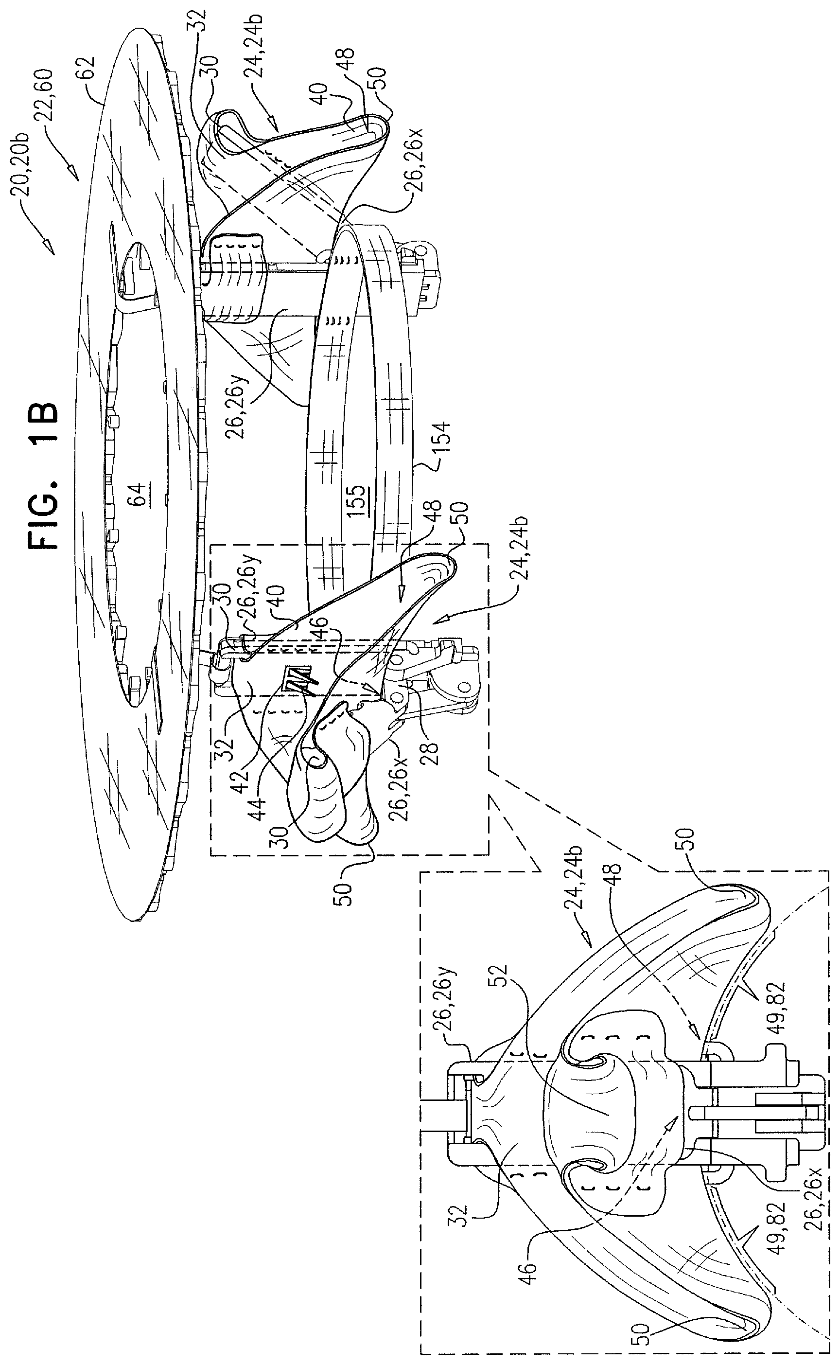
1. Apparatus for use with a prosthetic valve at a native valve of a heart of a subject, the apparatus comprising: a delivery tube, transluminally advanceable to the heart of the subject; and a prosthetic valve support, configured to support the prosthetic valve at the native valve, and defining an upstream support portion, the upstream support portion being a generally annular disc, and: having a working configuration in which the upstream support portion is a generally annular disc that has (1) a tissue-contacting side configured to be placed against an atrial surface of the native valve, and (2) an opposing side, and defines an opening therebetween, having a delivery configuration in which the upstream support portion is rolled up to create a channel having a central longitudinal axis, and is disposed within the delivery tube, and being configured to be transitioned from the delivery configuration to the working configuration by being exposed from the delivery tube, and unrolled.
2. The apparatus according to claim 1, wherein, in the delivery configuration, the upstream support portion has a distal portion and a proximal portion, and shapes the channel to be an uninterrupted lumen between the distal portion and the proximal portion.
3. The apparatus according to claim 1, wherein the delivery tube is configured to retain the upstream support portion in the delivery configuration, and the upstream support portion is configured to automatically transition toward the working configuration by automatically unrolling upon becoming exposed from the delivery tube.
4. The apparatus according to claim 1, wherein, while the upstream support portion is in the delivery configuration, at any given part of the upstream support portion, the opposing side of the upstream support portion is disposed closer to the central longitudinal axis than is the tissue-contacting side.
5. The apparatus according to claim 1, wherein, while the upstream support portion is in the delivery configuration, the central longitudinal axis of the channel is collinear with a central longitudinal axis of the delivery tube.
6. A method for use with a prosthetic valve at a native valve of a heart of a subject, comprising: transluminally advancing, to a heart valve of the subject, a prosthetic valve support that defines an upstream support portion, the advancing being while the upstream support portion is in a delivery configuration in which the upstream support portion (i) is rolled up to create a channel having a central longitudinal axis, and (ii) is disposed within a delivery tube; subsequently, facilitating transition of the upstream support portion into a working configuration by exposing the upstream support portion from the delivery tube and facilitating unrolling of the upstream support portion, the working configuration being a configuration in which: the upstream support portion is a generally annular disc that has (1) a tissue-contacting side, and (2) an opposing side, the upstream support portion defines an opening between the tissue-contacting side and the opposing side, and the tissue-contacting side is disposed against an atrial surface of the native valve; and using the prosthetic valve support, supporting the prosthetic valve at the native valve.
7. The method according to claim 6, wherein facilitating transition of the upstream support portion into the working configuration comprises exposing the upstream support portion from the delivery tube such that the upstream support portion automatically unrolls.
8. The method according to claim 6, wherein, in the delivery configuration, the upstream support portion has a proximal portion and a distal portion, the channel being defined between the proximal portion and the distal portion, and wherein the method further comprises pressing the distal portion against the annulus such that the distal portion deflects with respect to the delivery tube.
9. The method according to claim 6, wherein, in the delivery configuration, the upstream support portion has a proximal portion and a distal portion, the channel being defined between the proximal portion and the distal portion, and wherein the method further comprises pressing the distal portion against the annulus such that the distal portion deflects with respect to the proximal portion.
Description
FIELD OF THE INVENTION
Some applications of the present invention relate in general to valve replacement. More specifically, some applications of the present invention relate to prosthetic cardiac valves and techniques for implantation thereof.
BACKGROUND
Ischemic heart disease causes regurgitation of a heart valve by the combination of ischemic dysfunction of the papillary muscles, and the dilatation of the ventricle that is present in ischemic heart disease, with the subsequent displacement of the papillary muscles and the dilatation of the valve annulus.
Dilation of the annulus of the valve prevents the valve leaflets from fully coapting when the valve is closed. Regurgitation of blood from the ventricle into the atrium results in increased total stroke volume and decreased cardiac output, and ultimate weakening of the ventricle secondary to a volume overload and a pressure overload of the atrium.
SUMMARY OF THE INVENTION
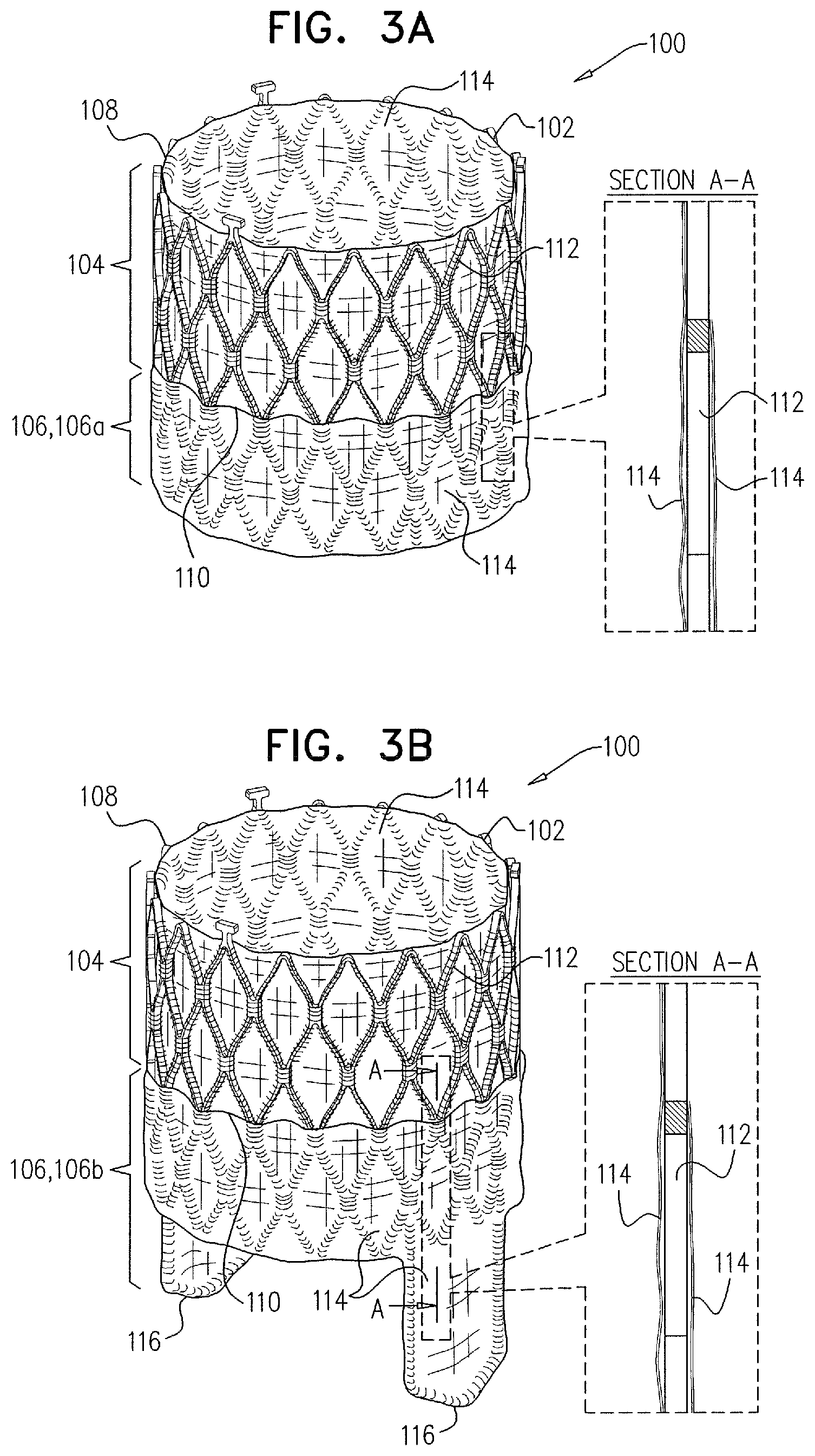
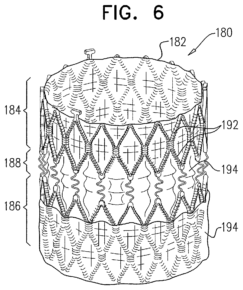
For some applications of the invention, a prosthetic valve support is provided for facilitating minimally invasive (e.g., transcatheter and/or transluminal) implantation of a prosthetic valve at a native valve of a subject. The native valve typically has native check valve functionality, i.e., it functions as a check valve. The prosthetic valve support is typically couplable to the native valve (e.g., to leaflets thereof) of the subject without eliminating the check valve functionality of the native valve. The prosthetic valve is subsequently implanted at the native valve by coupling the prosthetic valve to the prosthetic valve support, typically by expanding the prosthetic valve within an opening defined by the prosthetic valve support. The implantation of the prosthetic valve at the native valve replaces, at least in part, the check valve functionality of the native valve with substitute check valve functionality of the prosthetic valve. The prosthetic valve support comprises an upstream support portion, configured to be placed against an upstream surface of the native valve, and shaped to define an opening.
For some applications, the upstream support portion is delivered to the native valve in a delivery configuration (e.g., rolled within a delivery tube), and the tissue-engaging elements comprise tissue anchors that are driven through the upstream support portion and into the annulus of the native valve while at least part of the upstream support portion is still within the delivery tube (e.g., is still in the delivery configuration).
For some applications, the prosthetic valve support comprises tissue-engaging elements, such as clips. For some such applications, the clips comprise two arms, and a fabric which covers the arms, and typically has a greater surface area than the clip arms. The fabric is configured to cushion (e.g., soften and/or disperse) forces applied by the clips on the tissue to which the clip is coupled. The clips of the prosthetic valve support are typically coupled to leaflets of the native valve and are further typically configured to move with the native beating of the leaflets so as not to eliminate the check valve functionality of the native valve.
For some applications, tissue-engaging elements are coupled to the native valve (e.g., to the leaflets thereof) and the upstream support portion is subsequently coupled to the tissue-engaging elements. For such applications, each tissue-engaging element is typically coupled to a longitudinal guide member along (e.g., over) which the upstream support portion is slidable. For some such applications, the tissue-engaging elements comprise clips, configured to be coupled to the leaflets of the native valve. For some such applications, the tissue-engaging elements comprise tissue anchors that are coupled to the annulus.
For some applications in which the tissue-engaging elements comprise tissue anchors, more than one tissue anchor is delivered through one delivery tube. For example, the anchors may each fit snugly through the delivery tube, and be delivered sequentially.
As described hereinabove, a prosthetic valve is typically coupled to the prosthetic valve support after the prosthetic valve support has been coupled to the native valve. For some applications, the prosthetic valve comprises a valve body, and a downstream portion that is configured to inhibit contact between chordae tendineae of the heart and the valve body, such as to prevent damage to the chordae tendineae. Typically, an outer surface of the downstream portion is covered with a fabric. For some applications, the prosthetic valve comprises a valve body that comprises an upstream portion, a downstream portion, and an elastic portion between the upstream portion and the downstream portion. For some such applications, the prosthetic valve is configured to facilitate coupling of a pre-determined portion of the prosthetic valve to the prosthetic valve support (e.g., to the upstream support portion thereof).
There is therefore provided, in accordance with an application of the present invention, apparatus for use with a prosthetic valve at a native valve of a heart of a subject, the apparatus including:
a delivery tube, transluminally advanceable to the heart of the subject;
a prosthetic valve support, configured to support the prosthetic valve at the native valve, and including an upstream support portion, the upstream support portion: having a working configuration in which the upstream support portion is generally annular and has (1) a tissue-contacting side configured to be placed against an atrial surface of the native valve, and (2) an opposing side, and defines an opening therebetween, and having a delivery configuration in which the upstream support portion defines a channel having a central longitudinal axis, and is configured to be disposed within the delivery tube;
a tissue anchor, configured to be disposed within the channel, and slidable through at least part of the channel; and
an anchor driver, slidable within the delivery tube and the channel, and configured to anchor the upstream support portion to tissue of the heart by driving the tissue anchor from the opposing side through the upstream support portion and into the tissue, while at least part of the upstream support portion is disposed within the delivery tube.
In an application, the tissue anchor includes a helical tissue anchor, and is configured to be driven into the tissue by being rotated.
In an application, the upstream support portion is configured to be transitioned from the delivery configuration to the working configuration by being unrolled.
In an application:
in the delivery configuration, the upstream support portion has a distal portion and a proximal portion, and the channel is defined between the distal portion and the proximal portion,
the anchor includes a first anchor, and the anchor driver is configured to anchor the distal portion of the upstream support portion to the tissue by driving the first anchor through the distal portion of the upstream support portion, and
the apparatus is configured such that: the proximal portion of the upstream support portion is configured to be at least partly exposed from the delivery tube subsequently to the anchoring of the distal portion, and the apparatus further includes a second anchor, configured to be driven through the proximal portion of the upstream support portion and into the tissue subsequently to the exposing.
In an application, in the delivery configuration, the upstream support portion has a distal portion and a proximal portion, and shapes the channel to be an uninterrupted lumen between the distal portion and the proximal portion.
In an application, the anchor driver is configured to slide the tissue anchor through at least most of the channel before driving the anchor through the upstream support portion.
In an application, the delivery tube is configured to be transluminally advanced while the upstream support portion is disposed within a distal portion of the delivery tube, and while the tissue anchor and a distal portion of the anchor driver are disposed within the channel.
In an application, the delivery tube is configured to retain the upstream support portion in the delivery configuration, and the upstream support portion is configured to automatically transition toward the working configuration upon becoming exposed from the delivery tube.
In an application, in the delivery configuration, at any given part of the upstream support portion, the opposing side of the upstream support portion is disposed closer to the central longitudinal axis than is the tissue-contacting side.
In an application, while the upstream support portion is in the delivery configuration and disposed within the delivery tube, the channel shares a common central longitudinal axis with the delivery tube, and the anchor driver is configured to drive the tissue anchor through the upstream support portion by moving the tissue anchor along the common central longitudinal axis.
In an application, the delivery tube is configured to facilitate the driving of the tissue anchor through the upstream support portion by deflecting a portion of the prosthetic valve support to intersect with the common central longitudinal axis by pressing the portion of the prosthetic valve support against the tissue.
There is further provided, in accordance with an application of the present invention, a method for anchoring a prosthetic valve support to a native valve of a heart of a subject, the native valve having an annulus and a plurality of leaflets, the prosthetic valve support including an upstream support portion that is configured to be placed against an atrial surface of the annulus, the method including:
transluminally advancing, to the heart of the subject, the upstream support portion, while the upstream support portion (1) is in a delivery configuration thereof in which the upstream support portion has a distal portion and a proximal portion, and defines a channel therebetween, and (2) is disposed within a delivery tube;
advancing, out of a distal end of the delivery tube, the distal portion of the upstream support portion;
using an anchor driver at least a distal end of which is disposed within the channel, anchoring the distal portion of the upstream support portion to a site of the annulus by driving an anchor through the distal portion of the upstream support portion and into the site; and
subsequently, facilitating transition of the upstream support portion into a working configuration in which the upstream support portion is generally annular, and is disposed against the annulus.
In an application, transluminally advancing the upstream support portion includes transluminally advancing the delivery tube while the upstream support portion is disposed within a distal portion of the delivery tube, and while the tissue anchor and a distal portion of the anchor driver are disposed within the channel.
In an application, facilitating transition of the upstream support portion into the working configuration includes facilitating unrolling of the upstream support portion into the working configuration.
In an application, facilitating transition of the upstream support portion into the working configuration includes exposing the upstream support portion from the delivery tube such that the upstream support portion transitions automatically into the working configuration.
In an application, the method further includes advancing the tissue anchor through at least most of the channel prior to anchoring the distal portion.
In an application:
the anchor includes a first anchor, and the site includes a first site, and
the method further includes, subsequently to anchoring the distal portion, sliding the anchor driver proximally within the channel and subsequently anchoring, using a second anchor, a proximal portion of the upstream support portion to a second site of the annulus.
In an application, the method further includes pressing the distal portion against the site such that a plane of the distal portion is disposed at greater than 45 degrees with respect to a longitudinal axis of the delivery tube.
In an application:
while the upstream support portion is in the delivery configuration and disposed within the delivery tube, the channel shares a common central longitudinal axis with the delivery tube, and
driving the anchor through the distal portion includes driving the anchor through the distal wall by moving the tissue anchor along the common central longitudinal axis.
In an application:
the method further includes pressing the distal portion against the site such that the distal portion deflects with respect to a central longitudinal axis of the channel, and driving the tissue anchor through the distal portion includes moving the anchor driver distally within the channel while the distal portion is pressed against the site.
There is further provided, in accordance with an application of the present invention, a method for anchoring a prosthetic valve support to a native valve of a heart of a subject, the native valve having an annulus and a plurality of leaflets, the prosthetic valve support including an upstream support portion that is configured to be placed against an atrial surface of the annulus, the method including:
transluminally advancing, to the heart of the subject, the upstream support portion, while the upstream support portion (1) is in a delivery configuration thereof in which the upstream support portion generally defines a tube that defines a channel, and (2) is disposed within a delivery tube;
advancing, out of a distal end of the delivery tube, a distal portion of the upstream support portion in the delivery configuration thereof;
anchoring the distal portion to a first site of the annulus using an anchor that is reversibly coupled to an anchor driver, by moving the anchor driver distally within the channel of the tube defined by the upstream support portion; and
facilitating unrolling of the upstream support portion into a deployed configuration in which the upstream support portion is generally annular, and is disposed against the annulus.
In an application, the anchor includes a first anchor, and the method further includes anchoring, using a second anchor, a proximal portion of the upstream support portion to a second site of the annulus.
In an application, anchoring the distal portion of the upstream support portion to the first site includes bending the distal portion by pressing the distal portion against the first site, such that moving the anchor driver distally within the channel of the tube defined by the upstream support portion moves the anchor through the distal portion.
In an application, the method further includes pressing the distal portion against the first site such that a plane of the distal portion is disposed at greater than 45 degrees with respect to a longitudinal axis of the delivery tube.
There is further provided, in accordance with an application of the present invention, apparatus for facilitating implantation of an implant at a native valve of a heart of a subject, the apparatus including a tissue-engaging element, the tissue-engaging element including:
a first portion of the apparatus, including: at least one arm, having: a first end, a second end, and a longitudinal axis therebetween, and a face that has a length along the longitudinal axis of the arm, and a width that is orthogonal to the length, the length and the width defining an area of the face, and a fabric, coupled to the arm so as to have a length and a width that define an area of the fabric, the area of the fabric being greater than the area of the face; and
a second portion of the apparatus,
the first end of the arm of the first portion being articulatably coupled to the second portion at a hinge region, and the tissue-engaging element being configured to sandwich tissue in a vicinity of the native valve between the fabric and the second portion of the apparatus.
In an application, the tissue-engaging element is configured to sandwich tissue of the native valve between the fabric and the second portion of the apparatus.
In an application, the area of the fabric is more than twice as great as the area of the face.
In an application, the fabric entirely covers the face.
In an application, the apparatus further includes the implant, and the second portion of the apparatus includes a portion of the implant.
In an application, the fabric is generally shaped to define a saddle shape having a saddle point, the saddle point being disposed in a vicinity of the hinge region.
In an application:
the arm of the first portion includes a first arm, and the face of the first arm includes a first face,
the second portion of the apparatus includes a second arm, having: a first end, a second end, and a longitudinal axis therebetween, and a second face that has a length along the longitudinal axis of the second arm, and a width that is orthogonal to the length of the face of the second arm, the length and the width of second face defining an area of the second face,
the first end of the second arm is articulatably coupled to the first end of the first arm at the hinge region,
the fabric is coupled to the first arm and to the second arm, and is disposed over the first face and the second face, and
the area of the fabric is greater than the sum of the area of the first face and the area of the second face.
In an application, the first face extends laterally from the longitudinal axis of the first arm, the second face extends laterally from the longitudinal axis of the second arm, and the fabric extends further from the longitudinal axis of each of the first and second arms than does the width of the first and second faces, respectively.
In an application, the fabric extends, from the hinge region, further along the longitudinal axis of the first arm than does the first face.
In an application, a portion of the fabric is disposed over a second end of the first arm.
In an application, the portion of the fabric that is disposed over the second end of the first arm defines at least part of a cushion.
In an application, the cushion extends, from the second end of the first arm, away from the second arm.
There is further provided, in accordance with an application of the present invention, apparatus, for implantation at a native valve of a heart of a subject, the native valve including at least a first valve leaflet and a second valve leaflet, each leaflet being coupled to a respective plurality of chordae tendineae, the apparatus including:
a prosthetic valve, including: a tubular valve body, having an upstream end and a downstream end, and configured to be placed between the leaflets of the native valve; at least one valve member, configured to facilitate flow of blood of the subject from the upstream end of the valve body to the downstream end of the valve body, and to inhibit flow of the blood from the downstream end of the valve body to the upstream end of the valve body; and a downstream portion: coupled to the downstream end of the valve body, extending away from the downstream end of the valve body, configured to be placed between the plurality of chordae tendineae coupled to the first valve leaflet, and the plurality of chordae tendineae coupled to the second valve leaflet, and configured to inhibit contact between the chordae tendineae and the valve body.
In an application, the downstream portion includes a frame, and at least an outer surface of the frame is covered with a covering.
In an application, the downstream portion is tubular, and the downstream portion and the valve body define a continuous lumen therethrough.
In an application, the heart of the subject includes a plurality of papillary muscles, and at least part of the downstream portion is configured to be placed in contact with at least one of the papillary muscles.
In an application, the downstream portion includes one or more protrusions, each protrusion extending away from the downstream end of the valve body.
In an application, the valve body has a longitudinal axis therethrough, and includes a circumferential lateral wall that defines a curved plane that circumscribes the longitudinal axis, and the protrusions lie on the plane.
In an application, each protrusion has a transverse cross-sectional shape of an arc, and the arc of each protrusion lies on the curved plane defined by the valve body.
There is further provided, in accordance with an application of the present invention, apparatus, for implantation at a native valve of a heart of a subject, the native valve being disposed between an atrium and a ventricle of the heart, the apparatus including:
a tubular valve body: having an upstream portion, configured to be disposed in the atrium of the heart of the subject, having a downstream portion, configured to be disposed in the ventricle of the subject, having an elastic portion, disposed between the upstream portion and the downstream portion, and elastically coupling the upstream portion to the downstream portion, and shaped to define a continuous lumen through the upstream portion, the elastic portion, and the downstream portion; and
at least one valve member, disposed in the lumen of the valve body, and configured to facilitate flow of blood of the subject from the upstream portion of the valve body to the downstream portion of the valve body, and to inhibit flow of the blood from the downstream portion of the valve body to the upstream portion of the valve body.
In an application, the at least one valve member is coupled to the downstream portion of the valve body.
In an application, the native valve includes a plurality of native leaflets, and the downstream portion of the valve body is configured to be coupled to the native leaflets.
In an application, the apparatus further includes a plurality of clips, configured to facilitate the coupling of the downstream portion of the valve body to the native leaflets.
In an application, each clip:
includes at least two clip arms, articulatably coupled to each other, and
is reversibly closeable.
In an application, the clips are coupled to the downstream portion of the valve body, and the downstream portion of the valve body is configured to be coupled to the native leaflets by the clips being coupled to the native leaflets.
In an application, each clip of the plurality of clips is articulatably coupled to the downstream portion of the valve body.
In an application, the native valve includes an annulus having an upstream surface, and the apparatus further includes a prosthetic valve support:
including (1) an upstream support portion, configured to be placed against the upstream surface of the annulus of the native valve, and (2) the plurality of clips, coupled to the upstream support portion, and
shaped to define an opening therethrough that is configured to receive the prosthetic valve,
and the clips are configured to facilitate the coupling of the downstream portion of the valve body to the native leaflets by coupling the prosthetic valve support to the native leaflets.
There is further provided, in accordance with an application of the present invention, apparatus for facilitating implantation of a prosthetic valve at a native valve of a heart of a subject, the native valve having a plurality of native leaflets, the apparatus including:
at least one tissue-engaging element, configured to be transluminally delivered to the native valve, and to be coupled to a native leaflet of the subject;
an upstream support portion, configured to be transluminally delivered to the native valve, and to be intracorporeally coupled to the tissue-engaging element;
at least one locking element, configured to intracorporeally couple the tissue-engaging element to the upstream support portion such that the tissue-engaging element is movable with respect to the upstream support portion.
In an application, the tissue-engaging element includes a clip, having at least a first arm and a second arm, the first and second arms being articulatably coupled to each other, and the clip is reversibly openable and closeable.
In an application:
the first arm has a first face and the second arm has a second face,
the tissue-engaging element includes a fabric that is coupled to the first arm and to the second arm, and is disposed over the first face and the second face, and
the fabric defines an area that is greater than the sum of the area of the first face and the area of the second face.
In an application, the apparatus further includes a clip controller, configured to interface with the clip, and to facilitate the reversible opening and closing of the clip.
In an application, the apparatus further includes at least one flexible longitudinal guide member, and the apparatus is configured such that, when the locking element couples the tissue-engaging element to the upstream support portion, at least a portion of the flexible longitudinal guide member is disposed between the tissue-engaging element and the upstream support portion.
In an application:
the flexible longitudinal guide member is coupled to the locking element and to the tissue-engaging element,
the locking element is configured to couple the tissue-engaging element to the upstream support portion by the locking element being coupled to the upstream support portion, and
flexibility of the at least the portion of the flexible longitudinal guide member facilitates the coupling of the tissue-engaging element to the upstream support portion such that the tissue-engaging element is movable with respect to the upstream support portion.
There is further provided, in accordance with an application of the present invention, a method for anchoring a prosthetic valve support to a native valve of a subject, the native valve having an annulus and a plurality of leaflets, the method including:
transluminally advancing a delivery tube such that a distal end of the delivery tube is disposed in a vicinity of a first site of the annulus;
advancing a first anchor distally through the delivery tube by advancing an anchor driver through the delivery tube, the anchor driver having a distal end to which the first anchor is reversibly coupled, and the first anchor being coupled to a distal end of a first guide member;
anchoring the first anchor to tissue of the first site of the annulus using the anchor driver;
subsequently, decoupling the anchor driver from the first anchor, and proximally withdrawing the anchor driver such that at least a portion of the first guide member remains disposed within the delivery tube, and such that the distal end of the first guide member remains coupled to the first anchor;
subsequently, advancing a second anchor through the delivery tube such that the second anchor passes at least the portion of the first guide member, the second anchor being coupled to a distal end of a second guide member;
positioning the distal end of the delivery tube in a vicinity of a second site of the annulus; and
anchoring the second anchor to tissue of the second site of the annulus;
sliding the prosthetic valve support distally over the first guide member and the second guide member; and
anchoring the prosthetic valve support to the native valve by inhibiting further sliding of the prosthetic valve support with respect to the first guide member and the second guide member.
In an application:
transluminally advancing the delivery tube includes transluminally advancing a delivery tube through which the first anchor fits snugly and through which the second anchor fits snugly,
advancing the first anchor distally through the delivery tube includes advancing the first anchor distally through the delivery tube in which the first anchor fits snugly, and
advancing the second anchor distally through the delivery tube includes advancing the second anchor distally through the delivery tube in which the second anchor fits snugly.
In an application, advancing the anchor driver through the delivery tube includes advancing the anchor driver through a delivery tube through which the anchor driver fits snugly.
In an application, advancing anchor driver includes advancing an anchor driver that has a transverse cross-sectional area that is more than twice as great as a transverse cross-sectional area of the first guide member.
In an application, anchoring the first anchor, anchoring the second anchor, and anchoring the prosthetic valve support include anchoring the first anchor, anchoring the second anchor, and anchoring the prosthetic valve support without eliminating movement of the leaflets of the native valve.
In an application, anchoring the first anchor, anchoring the second anchor, and anchoring the prosthetic valve support include anchoring the first anchor, anchoring the second anchor, and anchoring the prosthetic valve support without engaging the leaflets of the native valve.
In an application, anchoring the first anchor at the first site of the annulus includes anchoring the first anchor at a first site of the annulus that is in the vicinity of a first commissure of the native valve, and anchoring the second anchor at the second site of the annulus includes anchoring the second anchor at a second site of the annulus that is in the vicinity of a second commissure of the native valve.
In an application, the method further includes advancing a guidewire to the first commissure of the native valve, the delivery tube being shaped to define a lateral opening through which the guidewire is slidable, and transluminally advancing the delivery tube to the first site of the annulus includes sliding the delivery tube over the guidewire.
In an application, transluminally advancing the delivery tube to the first site that is in the vicinity of the first commissure includes transluminally advancing the delivery tube to a first site that is a distance from the first commissure, the distance of the first site from the first commissure being at least in part dependent on a distance between the distal end of the delivery tube and the lateral opening of the delivery tube.
The present invention will be more fully understood from the following detailed description of applications thereof, taken together with the drawings, in which:
BRIEF DESCRIPTION OF THE DRAWINGS
FIGS. 1A-C and 2 are schematic illustrations of a system comprising an implant comprising one or more tissue-engaging elements, in accordance with some applications of the invention;
FIGS. 3A-B and 4A-B are schematic illustrations of a prosthetic valve that comprises a tubular valve body and a downstream portion, in accordance with some applications of the invention;
FIGS. 5A-D are schematic illustrations of a system comprising an upstream support portion, a plurality of tissue-engaging elements, a locking element, and a prosthetic valve, in accordance with some applications of the invention;
FIGS. 6 and 7A-B are schematic illustrations of a prosthetic valve having a tubular valve body that comprises an upstream portion, a downstream portion, and an elastic portion disposed between the upstream portion and the downstream portion, in accordance with some applications of the invention;
FIGS. 8-10 are schematic illustrations of a system for delivering and anchoring to a native valve, a prosthetic valve support comprising an upstream support portion, in accordance with some applications of the invention; and
FIGS. 11A-C are schematic illustrations of a system for delivering and anchoring to a native valve, a prosthetic valve support comprising an upstream support portion, in accordance with some applications of the invention.
DETAILED DESCRIPTION OF EMBODIMENTS
Reference is made to FIGS. 1A-C and 2, which are schematic illustrations of a system 20 comprising an implant 22, and apparatus for facilitating implantation of the implant at a native heart valve 10 of a subject, the apparatus comprising a tissue-engaging element 24, in accordance with some applications of the invention. FIG. 1A shows system 20 comprising a system 20a, and tissue-engaging element 24 comprising a tissue-engaging element 24a, in accordance with some applications of the invention. FIG. 1B shows system 20 comprising a system 20b, and tissue-engaging element 24 comprising a tissue-engaging element 24b, in accordance with some applications of the invention. FIG. 1C shows system 20 comprising a system 20c, and tissue-engaging element 24 comprising a tissue-engaging element 24c, in accordance with some applications of the invention. FIG. 2 shows system 20b having been implanted at native valve 10, in accordance with some applications of the invention.
Tissue-engaging element 24 (e.g., tissue-engaging elements 24a, 24b, and 24c) comprises at least one arm 26. Typically, element 24 comprises two arms 26 (e.g., a first arm 26x and a second arm 26y), which are articulatably coupled to each other at a hinge region 34. Each arm 26 has a length from a first end 28 thereof at hinge region 34, to a second end 30 thereof, and a longitudinal axis therebetween. Each arm 26 also has a face 32, which has a length along the longitudinal axis of the arm, a width that is orthogonal to the length, and an area defined by the width and the length.
Tissue-engaging element 24 is configured to sandwich tissue in the vicinity of the native heart valve using the at least one arm 26. Typically, element 24 is configured to sandwich the tissue between first arm 26x and second arm 26y. Alternatively, element 24 may comprise only one arm (e.g., arm 26x), coupled to another portion of the apparatus (e.g., a portion of implant 22), and may be configured to sandwich the tissue between arm 26x and the other portion of the apparatus. Typically, and as shown in FIG. 2, element 24 is configured to sandwich, between arms 26, tissue of the native heart valve, such as tissue of a native leaflet 12 of the native heart valve.
Tissue-engaging element 24 further comprises a fabric 40, coupled to arm 26 so as to have a length and a width that define an area of the fabric (e.g., an area of the fabric that is disposed over face 32). Typically, the area of fabric 40 is greater than the area of face 32, such that part of the fabric is disposed over face 32, and part of the fabric extends past the face. For example, FIGS. 1A and 1B show fabric 40 of tissue-engaging elements 24a and 24b, respectively, extending laterally (i.e., width-ways) from face 32 (that is, the width of the fabric is greater than the width of the face, and the fabric extends further from the longitudinal axis of the arm, than does the face). Similarly, FIGS. 1B and 1C show fabric 40 of tissue-engaging elements 24b and 24c, respectively, extending away from second end 30 of arm 26x (that is, the length of fabric 40 is greater than the length of face 32, and the fabric extends further along the longitudinal axis of the arm from the hinge, than does the face). Fabric 40 is configured to cushion (e.g., soften and/or disperse) forces applied by element 24 on the tissue to which element 24 is coupled.
It is to be noted that throughout this patent application, including the specification and the claims, the term "fabric" typically means a woven fabric, but may also include other sheet-like materials, such as sheets of polymer and/or silicone.
For some applications, the area of fabric 40 is more than twice as great as the area of face 32. For some applications, the fabric entirely covers face 32. Alternatively, fabric 40 may be shaped to define a hole 42 through which a portion of arm 26 (e.g., a portion of face 32 thereof) may contact the tissue being sandwiched (e.g., the tissue of the native leaflet). For example, and as shown in FIGS. 1A-C, arm 26y may be shaped to define one or more barbs 44, configured to protrude through hole 42, and pierce the tissue being sandwiched, so as to facilitate gripping of the tissue.
Typically, tissue-engaging elements 24 comprise two arms 26 (e.g., arms 26x and 26y) and two respective faces 32, and fabric 40 spans both faces, and is bent (e.g., folded) to define a trough 48 in the vicinity of hinge region 34, thereby forming a clip with two tissue-engaging surfaces comprising fabric 40, and corners 50 that define respective ends of the trough. Typically, the area of fabric 40 is greater than (e.g., more than twice as great as) the sum of the respective areas of both faces 32, and thereby at least part (e.g., more than half) of fabric 40 is not directly backed by an arm (e.g., a face thereof), thereby providing flexibility to the clip. For some applications, and as shown in FIGS. 1A-B for tissue-engaging elements 24a and 24b, fabric 40 is shaped, and coupled to arms 26, so as to define a saddle shape. A saddle point 46 of the saddle shape is typically disposed in the vicinity of hinge region 34 (e.g., at hinge region 34), such that "wings" 49 of the fabric protrude laterally (i.e., width-ways) from faces 32, and trough 48 curves downward toward corners 50.
As shown in the magnified area of FIG. 2, wings 49 of fabric 40 that protrude laterally from arms 26 engage the tissue being sandwiched (e.g., leaflets 12), and provide lateral flexible coupling regions 82 that cushion (e.g., soften and/or disperse) forces applied by tissue-engaging element 24 on leaflet 12. Typically, and as shown in the magnified area of FIG. 2, element 24 is coupled to leaflet 12 such that, for at least some chordae tendineae 86 that are coupled to the leaflet being sandwiched, the respective points at which the chordae tendineae are coupled to the leaflet are disposed within trough 48 of fabric 40, and the chordae tendineae extend out of corners 50, and toward the papillary muscle 14 to which they are coupled.
Typically, and as shown in FIGS. 1A-C, fabric 40 is disposed over second end 30 of at least arm 26x. For some applications, and as shown in FIGS. 1B-C, fabric 40 is shaped to define a cushion 52 in the vicinity of second end 30 of arm 26x. For some applications, cushion 52 comprises a soft material (e.g., enveloped by fabric 40). For some applications, and as shown in FIGS. 1B-C, cushion 52 extends from second end 30 of arm 26x, away from arm 26y. Cushion 52 is configured to cushion (e.g., soften and/or disperse) forces applied by element 24 on the tissue to which element 24 is coupled. As shown in FIG. 2, cushion 52 provides a cushioning region 84 that cushions (e.g., softens and/or disperses) forces applied by tissue-engaging element 24 on leaflet 12.
For some applications, and as shown in FIGS. 1A-C, implant 22 comprises a prosthetic valve support 60, comprising an upstream support portion 62, configured to be placed against an upstream surface of an annulus of the native valve, e.g., as shown in FIGS. 2A-B, and shaped to define an opening 64 that is configured to receive a prosthetic valve. For some applications, prosthetic valve support 60 comprises a stabilizing member 154, described in more detail hereinbelow with reference to FIGS. 5A-D, typically coupled to elements 24. For some applications, implant 22 comprises a prosthetic valve.
For some applications, tissue-engaging elements 24 are articulatably coupled to upstream support portion 62 such that, when prosthetic valve support 60 is coupled to the native valve, native movement (e.g., beating) of the leaflets of native valve 10 is not eliminated, and thereby check-valve functionality of the native valve is not eliminated. For some such applications, prosthetic valve support is thereby implantable without the use of cardiopulmonary bypass.
Reference is made to FIGS. 3A-B and 4A-B, which are schematic illustrations of apparatus 100 comprising a prosthetic valve 102 that comprises a tubular valve body 104 and a downstream portion 106, in accordance with some applications of the invention. Prosthetic valve 102 comprises at least one valve member, such as a prosthetic leaflet (not shown). Body 104 has an upstream end 108 and a downstream end 110, and downstream portion 106 is coupled to downstream end 110. Downstream portion 106 extends away (i.e., downstream) from downstream end 110, and is configured to inhibit contact between the chordae tendineae and valve body 104.
Typically, valve body 104 comprises a frame 112, such as a stent-like wire frame. For some applications, and as shown in FIGS. 3A-B, downstream portion 106 also comprises a frame. For some applications, frame 112 is shaped to define downstream portion 106 (e.g., body 104 and downstream portion 106 comprises respective portions of frame 112).
Typically, apparatus 100 (e.g., prosthetic valve 102 thereof) comprises a covering 114, disposed over (e.g., covering) an inner surface of frame 112. Typically, covering 114 is also disposed over an inner surface of downstream portion 106. Further typically, covering 114 is also disposed over an outer surface of portion 106 (e.g., extends around a distal end of apparatus 100). Sections A-A of FIG. 3A and FIG. 3B show such placements of covering 114.
FIG. 3A shows downstream portion 106 comprising a tubular downstream portion 106a, which is coupled to the downstream end of valve body 104 such that the downstream portion and the valve body define a continuous lumen therethrough. FIG. 3B shows downstream portion 106 a downstream portion 106b that comprises one or more (e.g., two) protrusions 116, each of which protrudes away from the valve body. Typically, protrusions 116 lie on a curved plane defined by valve body 104 (e.g., by a circumferential lateral wall of the valve body, such as that defined by frame 112), e.g., protruding downstream away from the valve body. For some applications, each protrusion 116 has a transverse cross-sectional shape of an arc, and the arc of each protrusion lies on the curved plane defined by valve body 104. For example, downstream portion 106b may resemble tubular downstream portion 106a having had portions thereof cut away.
As described hereinabove, downstream portion 106 is configured to inhibit contact between chordae tendineae 86 and valve body 104. As shown in FIG. 4B, for some applications, when apparatus 100 is implanted at the native valve, portion 106 (e.g., protrusions 116 thereof) is in contact with at least one (e.g., two) papillary muscles 14. For some such applications, portion 106 is configured to move the papillary muscles away from each other, and thereby to move at least portions of chordae tendineae 86 away from valve body 104. Covering 114 on the outer surface of portion 106 protects the chordae tendineae and/or papillary muscles from portion 106 (e.g., metallic components of the frame thereof). It is hypothesized that, for some applications, such inhibition of contact between the chordae tendineae and the valve body reduces a likelihood of damage to the chordae tendineae and/or improves blood flow through prosthetic valve 102.
Reference is made to FIGS. 5A-D, which are schematic illustrations of a system 140 comprising an upstream support portion 142, a plurality of tissue-engaging elements 144, a locking element 146, and a prosthetic valve 148, in accordance with some applications of the invention. System 140 is configured such that upstream support portion 142 is couplable to tissue-engaging elements 144 (1) intracorporeally, (2) subsequent to coupling of the tissue-engaging elements to tissue of native valve 10, and (3) prior to coupling of prosthetic valve 148 to the upstream support portion. For some applications of the invention, upstream support portion 142 and tissue-engaging elements 144, when coupled to each other, act as a prosthetic valve support 150.
FIG. 5A shows two tissue-engaging elements 144 being coupled to respective leaflets 12 of native valve 10. For some applications, and as shown in FIGS. 5A-D, elements 144 comprise clips that are reversibly openable and closeable, and comprise a clip controller interface that facilitates the reversible opening and closing by interfacing (e.g., reversibly interfacing) with a clip controller 152. For some applications, tissue-engaging elements 144 are delivered within a delivery tube 145. Typically, system 140 (e.g., prosthetic valve support 150 thereof) further comprises a stabilizing member 154, such as a stabilizing band, coupled to tissue-engaging elements 144, and configured to form a ring that is shaped to define an opening 155 therethrough (shown in FIGS. 1A-C for stabilizing member 154 of system 20).
As shown in FIGS. 5A-B, tissue-engaging elements 144 are typically able to move toward and away from each other, following coupling thereof to leaflets 12. It is hypothesized that such movement allows the leaflets of the native valve to continue to move, and therefore facilitates coupling of the tissue-engaging elements to the native valve (e.g., to the leaflets thereof) without eliminating the native valve function. As also shown in FIGS. 5A-B, stabilizing member 154 is typically flexible, so as to facilitate such movement of tissue-engaging elements 144. For example, when the tissue-engaging elements are disposed away from each other (e.g., when leaflets 12 are open; FIG. 5B), member 154 may form the ring that is shaped to define the opening therethrough, and when the tissue-engaging elements are disposed close to each other (e.g., when leaflets 12 are closed; FIG. 5A, mutatis mutandis), member 154 may form a general lemniscate.
FIGS. 5B-C show, subsequent to the coupling of tissue-engaging elements 144 to leaflets 12, upstream support portion 142 being delivered to the upstream (e.g., atrial) surface of the annulus of native valve 10, and coupled to the tissue-engaging elements. Upstream support portion 142 is typically delivered in a compressed (e.g., crimped) configuration within a delivery tube 156. FIG. 5B shows upstream support portion 142 being deployed out of delivery tube 156 and expanding (e.g., automatically expanding) toward an expanded configuration thereof. For some applications, delivery tube 156 comprises delivery tube 155. That is, for some applications, upstream support portion 142 is delivered within and/or via the same delivery tube as are tissue-engaging elements 144.
Typically, locking element 146 comprises a ratcheting element 158, comprising a plurality of ratchet teeth 160. Further typically, system 140 (e.g., prosthetic valve support 150 thereof) comprises a plurality of longitudinal guide members 162, each longitudinal guide member coupled to a respective tissue-engaging element, and each locking element 146 (e.g., ratcheting element 158) is coupled to and/or defined by a respective longitudinal guide member. Upstream support portion 142 is slidable along longitudinal guide members 162 (e.g., each longitudinal guide member is slidable through a respective hole 164 defined by the upstream support portion), typically by being pushed along the longitudinal guide members by one or more pushers 168 that are themselves typically slidable over the longitudinal guide members. Such sliding is typically facilitated by providing a counter force by simultaneous pulling on longitudinal guide members 162.
As shown in FIG. 5C, upstream support portion 142 typically comprises a plurality of receiving elements 166, disposed at a respective hole 164, and configured (1) to allow slidable passage of a respective longitudinal guide member 162 through the respective hole, and (2) to couple (e.g., lock) to a respective locking element 146. For example, each receiving element may comprise an eyelet, disposed around a respective hole, and configured to facilitate one-way movement therethrough of ratcheting element 158.
Coupling of upstream support portion 142 to tissue-engaging elements 144 thereby forms prosthetic valve support 150. Typically, tissue-engaging elements 144 are flexibly coupled to upstream support portion 142 (i.e., can move with respect to the upstream support portion while coupled to the upstream support portion). For example, longitudinal guide members 162 are typically flexible, and a portion of each flexible longitudinal guide member is disposed between a respective tissue-engaging element 144 (i.e., the point at which the longitudinal guide member is coupled to the tissue-engaging element) and upstream support portion 142 (i.e., the point at which the longitudinal guide member is coupled to the upstream support portion). Such coupling typically configures prosthetic valve support 150 to be couplable to native valve 10 without eliminating the valve function thereof, e.g., as described hereinabove. Upstream support portion 142 is typically annular, and shaped to define an opening therethrough, through which blood may flow.
Typically, a proximal portion of each longitudinal guide member 162 is decoupled from a distal portion of that longitudinal guide member and/or from the respective locking element 146, such as, but not limited to, by cutting. Such decoupling may be performed before introduction of prosthetic valve 148, as shown, or subsequently thereto.
Subsequently to coupling of upstream support portion 142 to tissue-engaging elements 144 (and thereby formation of prosthetic valve support 150), prosthetic valve 148 is delivered to native valve 10 and coupled to the tissue-engaging elements (e.g., to the prosthetic valve support) (FIG. 5D). Typically, prosthetic valve 148 comprises an expandable prosthetic valve, and is deployed (e.g., from a delivery tube 149) such that it (1) expands within the opening defined by upstream support portion 142 and/or the opening defined by stabilizing member 154, (2) applies a radially-expansive force against the upstream support portion and/or the stabilizing member, and (3) thereby becomes coupled thereto. For clarity, prosthetic valve 148 is shown in phantom outline.
Reference is made to FIGS. 6 and 7A-B, which are schematic illustrations of a prosthetic valve 180 having a tubular valve body 182 that comprises an upstream portion 184, a downstream portion 186, and an elastic portion 188 disposed between the upstream portion and the downstream portion, in accordance with some applications of the invention. Prosthetic valve 180 is shaped to define a continuous lumen through portions 184, 188, and 186. Prosthetic valve 180 is configured to be implanted at native valve 10 such that an upstream portion 184 is disposed in an atrium 6 of the heart of the subject, and such that downstream portion 186 is disposed in a ventricle 8 of the heart of the subject. For example, prosthetic valve 180 may be coupled to a prosthetic valve support 190 that has previously coupled to the native valve. Prosthetic valve support 190 typically comprises tissue-engaging elements 144, upstream support portion 142, and stabilizing member 154, described hereinabove. For some applications, prosthetic valve support 190 comprises prosthetic valve support 150, described hereinabove. For some applications, prosthetic valve support 190 comprises a prosthetic valve support that comprises tissue-engaging elements 144, upstream support portion 142, and stabilizing member 156 that are provided pre-coupled to each other. For some applications, prosthetic valve support 190 may comprise another prosthetic valve support.
Tubular valve body 182 typically comprises a frame 192, such as a stent-like wire frame. As shown in FIG. 6, prosthetic valve 180 typically further comprises a covering 194, disposed over (e.g., covering) an inner surface of frame 192, thereby providing a sealed lumen from an upstream end to a downstream end of the tubular valve body. Typically, an excess of covering 194 is provided in the vicinity of elastic portion 188, so as to facilitate elastic stretching of the elastic portion.
Typically, prosthetic valve 180 comprises an expandable prosthetic valve, and is deployed such that it (1) expands within the opening defined by upstream support portion 142 and/or the opening defined by stabilizing member 154, (2) applies a radially-expansive force against the upstream support portion and/or the stabilizing member, and (3) thereby becomes coupled thereto. Typically, and as shown in FIGS. 7A-B, downstream portion 186 is expanded and coupled to stabilizing member 154 before upstream portion 184 is expanded and coupled to upstream support portion 142. While downstream portion 186 is coupled to member 154, and before upstream portion 184 is coupled to portion 142, elastic portion 188 may be stretched and compressed e.g., such as by moving upstream portion 184 further upstream and downstream. Such stretching and compressing changes a length of prosthetic valve 180, and for some applications, facilitates the coupling of a pre-determined portion of the prosthetic valve (e.g., of upstream portion 184) to upstream support portion 142, irrespective, to some degree, of (a) a distance between tissue-engaging elements 144 and upstream support portion 142, and/or (b) a dimension of native valve 10 (e.g., a length of leaflets 12). For some applications, such stretching and compressing adjusts a degree of tension of elastic portion 188, and may alternatively or additionally facilitate "tightening" of leaflets 12 against the implanted apparatus, such as drawing of the leaflets toward upstream support portion 142.
Reference is made to FIGS. 8-10, which are schematic illustrations of a system 200 for delivering and anchoring, to native valve 10, a prosthetic valve support 202 comprising an upstream support portion 204, in accordance with some applications of the invention. For some applications of the invention, prosthetic valve support 202 (and/or upstream support portion 204 thereof) comprises another prosthetic valve support described herein (and/or the upstream support portion thereof), such as prosthetic valve support 60 (and/or upstream support portion 62) or prosthetic valve support 150 (and/or upstream support portion 142).
Reference is now made to FIG. 8. System 200 comprises a delivery tube 206, which is shaped to define a lumen therethrough. A guidewire 208 protrudes from a lateral wall of delivery tube 206, such as from a hole 210 in the lateral wall. For some applications, tube 206 is shaped to define a secondary lumen that ends at hole 210, so as to provide guidewire 208 with a dedicated lumen. Guidewire 208 is advanced between leaflets 12 of native valve 10, such that the guidewire is disposed at a join of the leaflets, i.e., at a commissure 16 of the native valve (state A). Guidewire 208 is at least partly stiff, and provides resistance, which facilitates positioning of a distal end of tube 206. For example, guidewire 208 may bias the distal end to be disposed at a site in an arc around the commissure, the arc including part of the annulus and/or being in a vicinity of a fibrous trigone 17. For some applications, guidewire 208 is advanced between leaflets 12 and tube 206 is subsequently slid along (e.g., over) the guidewire. For some applications, tube 206 is advanced with guidewire 208.
A tissue anchor 220 (e.g., a first tissue anchor 220a) is advanced through at least a distal portion of tube 206, and is anchored to tissue of the native valve, such as tissue of the annulus of the native valve (state A). Typically, anchor 220 is advanced using an elongate anchor driver 222. For some applications, anchor 220 comprises a helical anchor, and is anchored to the tissue by being rotated using anchor driver 222.
Anchor driver 222 is reversibly coupled to anchor 220a, and is subsequently decoupled from the anchor and withdrawn proximally (e.g., withdrawn from the body of the subject) (state B). Anchor 220a is coupled to a longitudinal guide member 224 (e.g., a first guide member 224a), which is exposed from a lumen of anchor driver 222 when the driver is withdrawn (i.e., is slid proximally off of member 224). It is to be noted that at least a portion of guide member 224a remains disposed within tube 206. Tube 206 is moved toward a second commissure 14 of valve 10, and positioning of the tube is typically facilitated by guidewire 208 being disposed between leaflets 12 at the commissure, as described hereinabove.
A tissue anchor 220 (e.g., a second tissue anchor 220b) is advanced through at least a distal portion of tube 206, and is anchored to tissue of the native valve, such as tissue of the annulus of the native valve (state B). Typically, anchor 220b is advanced using an elongate anchor driver, such as the same anchor driver 222, or a second anchor driver. It is to be noted that anchor 220 and anchor driver 222 are advanced through tube 206 while at least a portion of first guide member 224a is disposed within tube 206 (i.e., advanced past at least a portion of member 224a).
Anchor driver 222 is subsequently decoupled from anchor 220b and is withdrawn proximally (e.g., withdrawn from the body of the subject) (state C). Anchor 220b is coupled to a longitudinal guide member 224 (e.g., a second guide member 224b), which is exposed from the lumen of anchor driver 222 when the driver is withdrawn. Native valve is thereby left with respective distal ends of two guide members 224 coupled thereto (e.g., coupled to the annulus thereof)(state D).
Reference is now made to FIG. 9. Prosthetic valve support 202 (e.g., upstream support portion 204 thereof) is advanced along (e.g., slid over) guide members 224 (e.g., guide members 224a and 224b) (state A). Typically, support 202 is advanced through delivery tube 206 in a compressed configuration (e.g., a generally cylindrical configuration), and automatically expands into an expanded configuration (e.g., a generally annular configuration) when deployed from the distal end of tube 206. Typically, support 202 is pushed through delivery tube 206 and against the upstream (e.g., atrial) surface of valve 10 using one or more control tubes 226 (e.g., a first control tube 226a and a second control tube 226b). Prosthetic valve support 202 (e.g., upstream support portion 204 thereof) is shaped to define one or more (e.g., two) holes, through which a respective guide member 224 is slidable. Control tubes 226 are shaped to define a lumen through which a respective guide member 224 is slidable, and typically have a transverse width (e.g., a diameter) that is greater than a diameter of the holes in prosthetic valve support 202. Thereby when control tubes 226 are slid distally over guide members 224, they push prosthetic valve support 202 distally (states A and B).
Subsequently, prosthetic valve support 202 is anchored to native valve 10 by inhibiting movement of the prosthetic valve support with respect to guide members 224. For example, a stopper 228 may be slid along each guide member and fastened to the guide member in the vicinity of the prosthetic valve support. For some applications, each guide member 224 comprises two discrete filaments, each filament being slidable through a separate hole in the prosthetic valve support, and the prosthetic valve support is anchored by tying the filaments together, optionally facilitated by a pledget (not shown). Typically, a proximal portion of each guide member is subsequently removed, such as by decoupling that portion from a distal portion, e.g., by cutting.
Reference is now made to FIG. 10. Subsequently, a prosthetic valve 230 is implanted at native valve 10 by being deployed at, and coupled to, prosthetic valve support 202, e.g., as described hereinabove for prosthetic valve 148 with reference to FIG. 5D, mutatis mutandis. For some applications, prosthetic valve 230 comprises tissue-engaging elements 232, such as anchors and/or clips, which facilitate implantation of the prosthetic valve by coupling to leaflets 12 of valve 10. For some such applications, and as shown with reference to FIG. 10, prosthetic valve 148 is partially deployed (state A), and then withdrawn proximally before being fully deployed (state B), so as to sandwich leaflets 12 against prosthetic valve support 202 (e.g., upstream support portion 204 thereof).
Reference is again made to FIGS. 8-10. Typically, each anchor 220 fits snugly through delivery tube 206. Typically, first guide member 224a is sufficiently thin to allow second anchor 220b to snugly fit through the delivery tube and past member 224a. For some applications, anchor driver 222 also fits snugly through delivery tube 206 and/or past member 224a. For example, guide member 224a may have a transverse cross-sectional area that is less than half (e.g., less than 25%, such as less than 10%) of a cross-sectional area of anchor 200 and/or anchor driver 222. For some applications, prosthetic valve support 202 (e.g., upstream support portion 204 thereof), in the compressed configuration thereof, fits snugly through delivery tube 206 and/or past guide members 224. For some applications, prosthetic valve 230, in a compressed configuration thereof, fits snugly through delivery tube 206.
For some applications, anchor 200, prosthetic valve support 202 in the compressed configuration thereof, and prosthetic valve 230 in the compressed configuration thereof, have respective transverse cross-sectional areas that are generally the same as each other (e.g., having a difference of less than 50%, such as less than 30%, such as less than 10%). For example, prosthetic valve support in the compressed configuration is typically less than 50% (e.g., less than 30%, such as less than 10%) wider than each anchor 200. For some such applications, this provides an efficient use of space within delivery tube 206, and thereby allows the use of a narrow delivery tube, e.g., because none of the anchor, support, or valve are more than 50% wider than another. In contrast, for some applications in which two or more anchors and/or anchor drivers are delivered in parallel, a delivery tube would have to be significantly wider than (e.g., twice as wide as) the delivery tube of system 200.
Reference is made to FIGS. 11A-C, which are schematic illustrations of a system 250 for delivering and anchoring to native valve 10, a prosthetic valve support 252 comprising an upstream support portion 254, in accordance with some applications of the invention. Prosthetic valve support 252 is delivered, via a delivery tube 256, to native valve 10 in a delivery configuration in which the prosthetic valve support (e.g., upstream support portion 254 thereof) assumes a shape that generally defines a channel (e.g., a lumen) therethrough, such as a generally tubular (e.g., cylindrical) shape. For example, upstream support portion 254 typically has expanded working configuration in which it is generally annular (FIG. 11A state D), and is "rolled" into the delivery configuration (e.g., into a generally tubular shape).
FIGS. 11B-C show upstream support portion 254 in the delivery configuration thereof, in accordance with respective applications of the invention. In both FIG. 11B and FIG. 11C, state A shows the upstream support portion in the annular expanded configuration, and state B shows the upstream support portion in the tubular delivery configuration. FIG. 11B shows an application in which upstream support portion 254 comprises an upstream support portion 254' which, in the annular expanded configuration thereof, has an outer diameter d1' and an inner diameter d2'. FIG. 11C shows an application in which upstream support portion 254 comprises an upstream support portion 254'' which, in the annular expanded configuration thereof, has an outer diameter d1'' and an inner diameter d2''. Upstream support portions 254' and 254'' are typically identical except that inner diameter d2' is smaller with respect to outer diameter d1', than is inner diameter d2'' with respect to outer diameter d1'', and therefore upstream support portion 254' has a greater surface area than does upstream support portion 254''.
State B of FIGS. 11B-C show upstream support portions 254' and 254'' in their respective delivery configurations. Upstream support portion 254' defines a generally continuous tubular shape having a distal end 260, a proximal end 262, and a generally continuous, uninterrupted channel 255' therebetween along a central longitudinal axis 258 defined by the upstream support portion. Due to its greater relative inner diameter, upstream support portion 254'' defines a tubular shape in which a channel 255'' between distal end 260 and proximal end 262 is interrupted and/or incomplete. FIG. 11C shows an example in which upstream support portion 254'' defines a distal tubular region 261, a proximal tubular region 263, and at least one interruption 265 therebetween. That is, at at least one part of the upstream support portion, compared to an uninterrupted tube, at least one portion of the lateral wall of the tube is absent. Nevertheless, upstream support portion 254'', in the delivery configuration thereof, also defines a channel 255'' therethrough.
The upstream support portion configurations in FIGS. 11B and 11C are intended to illustrate different applications in which the upstream support portion, in the delivery configuration thereof, defines a channel. These figures are not intended to limit the scope of the invention to these particular applications. For example, the scope of the invention includes, inter alia, as shown in state C of FIG. 11B, a delivery configuration in which only opposing edges of the upstream support portion touch, such that few, if any, portions of the lateral wall of the tubular shape completely circumscribe a given longitudinal site of the tubular shape. Nevertheless, the upstream support portion, in this delivery configuration, also defines a channel therethrough.
Upstream support portion 254 has a tissue-contacting side 274, configured to be placed against the atrial surface of valve 10 (e.g., against the annulus of the valve), and an opposing side 276, and defines an opening 278 therebetween. It is to be noted that, in the delivery configuration, opposing side 276 is disposed closer to central longitudinal axis 258 than is tissue-contacting side 274.
Reference is again made to FIG. 11A. Distal portion 260 of upstream support portion 254 is anchored to a first site of the annulus of the native valve using a tissue-engaging element, such as a tissue anchor 280 (e.g., a first tissue anchor 280a) (state A). Typically, anchor 280 is driven through upstream support portion 254 and into the tissue using an anchor driver 272, which is disposed within delivery tube 256. Typically, anchor driver 272 is slidable through the channel defined by the generally tubular shape of the upstream support portion, and is configured to move anchor 280a through at least part of that channel. For some applications, anchor 280 comprises a helical tissue anchor, and is anchored by being rotated by anchor driver 272. Anchor 280 may alternatively comprise a different type of tissue anchor, such as a harpoon-like tissue anchor.
Typically, distal portion 260 is anchored by (1) exposing the distal portion from delivery tube 256 and pressing it against the tissue of the annulus such that it deflects (e.g., bends) back and is disposed generally in front of the channel defined by the remainder of the upstream support portion that is disposed in the delivery configuration within tube 256, and (2) advancing anchor 280 distally through the upstream support portion (i.e., through distal portion 260 thereof) and into the tissue. For some applications, a plane defined by the distal portion is disposed at greater than 45 degrees with respect to longitudinal axis 258.
For some applications, during transluminal advancement, anchor 280a is disposed proximally to upstream support portion 254 (e.g., within a proximal portion of the delivery tube, or outside of the body of the subject), and driver 272 subsequently moves the anchor from a proximal end of the channel defined by the upstream support portion, through the channel. That is, driver 272 may slide anchor 280a past at least part of the longitudinal axis of upstream support portion 254 (e.g., past most of the longitudinal axis of the upstream support portion, such as past at least 80 percent of the longitudinal axis of the upstream support portion). Alternatively, during transluminal advancement, anchor 280a and a distal portion of anchor driver 272 may be already disposed within the channel defined by the upstream support portion, and the driver subsequently moves anchor 280a only slightly distally so as to drive the anchor through distal portion 260 and into the tissue. For some such applications, the delivery tube is transluminally advanced while the upstream support portion is disposed within a distal portion of the delivery tube, and the tissue anchor and the distal portion of the anchor driver are disposed within the channel.
Subsequently, upstream support portion 254 is further exposed from delivery tube 256 (e.g., by withdrawing the delivery tube proximally), and the distal end of the delivery tube is moved toward a second site of the annulus (state B). As upstream support portion 254 is progressively exposed from delivery tube 256, the upstream support portion typically progressively transitions (e.g., expands and/or unrolls) automatically toward the working configuration thereof. To facilitate such automatic transition toward the working configuration, upstream support portion 254 may comprise a frame (e.g., comprising a shape-memory material such as nitinol), which may be covered in a covering, such as a fabric.
Subsequently, a proximal portion 262 of upstream support portion 254 is anchored to the second site using a tissue anchor 280 (e.g., a second tissue anchor 280b) in a similar manner to that described for distal portion 260 (state C). Typically, during anchoring of proximal portion 262, the proximal portion is held near the distal end of delivery tube 256 by a deployment tool (e.g., slightly inside the delivery tube or just outside of the delivery tube). The deployment tool is not visible in state C; it is obscured by anchor driver 272. Following anchoring, proximal portion 262 is released by the deployment tool, and delivery tube 256 and driver 272 are withdrawn (state D).
It is to be noted that when prosthetic valve support 252 is disposed within delivery tube 256, the delivery tube and the prosthetic valve support (e.g., upstream support portion 254 thereof) share a common central longitudinal axis (e.g., are coaxial) (e.g., axis 258; FIGS. 11B-C), and that system 250 facilitates the driving of anchors through the prosthetic valve support by deflecting the portion of the prosthetic valve support that is to be anchored to intersect with the longitudinal axis, such that anchoring is possible by movement of the anchors (and anchor driver 272) along the longitudinal axis.
Prosthetic valve support 252 is typically subsequently used to facilitate implantation of a prosthetic valve, such as a prosthetic valve described hereinabove, or another prosthetic valve, e.g., by the prosthetic valve being expanded within the opening defined by the prosthetic valve support. Reference is again made to FIGS. 1A-11C. Typically, the techniques described hereinabove are performed transluminally (e.g., transfemorally). For some applications, the techniques are performed intercostally. It is therefore to be noted that the orientations and positions of the apparatus shown hereinabove with respect to atrium 6 of the subject are for clarity, and are not intended to limit the invention to a particular route to the atrium. Similarly, for some applications, the techniques described hereinabove are performed transapically, and thereby apparatus is delivered to the native valve via left ventricle 8 of the subject. It is to be further noted that, although native valve 10 is shown hereinabove as the mitral valve of the subject, the techniques described hereinabove may be used on other heart valves of the subject, such as the tricuspid valve, mutatis mutandis.
Reference is again made to FIGS. 1A-11C. For some applications, the prosthetic valve support is implanted (e.g., coupled to the native valve) without eliminating native functioning of the native leaflets. Thereby, for such applications, the prosthetic valve support (and for some such applications, the prosthetic valve) may be implanted without the use of cardiopulmonary bypass. For example: Tissue-engaging elements 24 (FIGS. 1A-C) and 144 (FIGS. 5A-D) are typically configured to move with the movement of the native leaflets (e.g., by deflecting with respect to the respective upstream support portion). Prosthetic valve support 202 (FIGS. 8-10) and 252 (FIG. 11) are typically anchored to the annulus of the native valve without contacting the native leaflets.
Reference is again made to FIGS. 1A-11C. For some applications, a separate prosthetic valve support is not used, but rather the upstream support portion is integral with the prosthetic valve (e.g., is coupled to the upstream end of the generally tubular valve body).
Reference is again made to FIGS. 1A-11C. It is to be noted that elements and/or techniques described herein with reference to a particular figure may be combined and/or substituted with elements and/or techniques described herein with reference to one or more other figures, mutatis mutandis. In particular, for some applications, elements of apparatus described herein are interchangeable with other elements that have the same name, mutatis mutandis. For example: For some applications, prosthetic valve 148 comprises, or may be substituted with, prosthetic valve 102, prosthetic valve 180, or prosthetic valve 230, mutatis mutandis. For some applications, upstream support portion 142 comprises, or may be substituted with, upstream support portion 62, upstream support portion 204, or upstream support portion 254, mutatis mutandis. For some applications, tissue-engaging element 232 comprises, or may be substituted with, tissue-engaging element 24 or tissue-engaging element 144, mutatis mutandis.
It will be appreciated by persons skilled in the art that the present invention is not limited to what has been particularly shown and described hereinabove. Rather, the scope of the present invention includes both combinations and subcombinations of the various features described hereinabove, as well as variations and modifications thereof that are not in the prior art, which would occur to persons skilled in the art upon reading the foregoing description.
* * * * *
References
D00000
D00001
D00002
D00003
D00004
D00005
D00006
D00007
D00008
D00009
D00010
D00011
D00012

D00013

D00014

D00015

D00016

D00017

D00018

XML
uspto.report is an independent third-party trademark research tool that is not affiliated, endorsed, or sponsored by the United States Patent and Trademark Office (USPTO) or any other governmental organization. The information provided by uspto.report is based on publicly available data at the time of writing and is intended for informational purposes only.
While we strive to provide accurate and up-to-date information, we do not guarantee the accuracy, completeness, reliability, or suitability of the information displayed on this site. The use of this site is at your own risk. Any reliance you place on such information is therefore strictly at your own risk.
All official trademark data, including owner information, should be verified by visiting the official USPTO website at www.uspto.gov. This site is not intended to replace professional legal advice and should not be used as a substitute for consulting with a legal professional who is knowledgeable about trademark law.