Implant for heart valve
Gross , et al.
U.S. patent number 10,226,341 [Application Number 15/197,069] was granted by the patent office on 2019-03-12 for implant for heart valve. This patent grant is currently assigned to CARDIOVALVE LTD.. The grantee listed for this patent is CARDIOVALVE LTD.. Invention is credited to Yossi Gross, Gil Hacohen, Meir Kutzik, Eran Miller, Rotem Neeman, Tal Reich, Yuval Zipory.


View All Diagrams
| United States Patent | 10,226,341 |
| Gross , et al. | March 12, 2019 |
Implant for heart valve
Abstract
For some applications, apparatus is provided for facilitating implantation of a prosthetic valve at a native heart valve of a subject, the apparatus comprising a prosthetic valve support, the prosthetic valve support (a) being configured to be transluminally-deliverable to the native valve and to be deployable at the native valve, and (b) comprising one or more tissue-engaging elements, configured to couple the prosthetic valve support to leaflets of the native valve without eliminating check valve functionality of the native valve. Other embodiments are also described.
| Inventors: | Gross; Yossi (Moshav Mazor, IL), Hacohen; Gil (Ramat Gan, IL), Miller; Eran (Moshav Beit Elazari, IL), Zipory; Yuval (Modi'in, IL), Reich; Tal (Moshav Moledet, IL), Kutzik; Meir (Holon, IL), Neeman; Rotem (Yeshuv Nirit, IL) | ||||||||||
|---|---|---|---|---|---|---|---|---|---|---|---|
| Applicant: |
|
||||||||||
| Assignee: | CARDIOVALVE LTD. (Or Yehuda,
IL) |
||||||||||
| Family ID: | 49231793 | ||||||||||
| Appl. No.: | 15/197,069 | ||||||||||
| Filed: | June 29, 2016 |
Prior Publication Data
| Document Identifier | Publication Date | |
|---|---|---|
| US 20160310274 A1 | Oct 27, 2016 | |
Related U.S. Patent Documents
| Application Number | Filing Date | Patent Number | Issue Date | ||
|---|---|---|---|---|---|
| 14237258 | 9387078 | ||||
| PCT/IL2012/000293 | Aug 5, 2012 | ||||
| 13412814 | Mar 6, 2012 | 8852272 | |||
| 61588892 | Jan 20, 2012 | ||||
| 61555160 | Nov 3, 2011 | ||||
| 61537276 | Sep 21, 2011 | ||||
| 61525281 | Aug 19, 2011 | ||||
| 61515372 | Aug 5, 2011 | ||||
| Current U.S. Class: | 1/1 |
| Current CPC Class: | A61F 2/2409 (20130101); A61F 2/2439 (20130101); A61F 2/2436 (20130101); A61F 2/2442 (20130101); A61F 2/2454 (20130101); A61F 2/2466 (20130101); A61F 2/2418 (20130101); A61F 2250/0069 (20130101); A61F 2220/0025 (20130101); A61F 2250/0015 (20130101); A61F 2250/0071 (20130101); A61F 2/848 (20130101); A61F 2220/0091 (20130101); A61F 2230/0006 (20130101); A61F 2230/0013 (20130101); A61F 2250/006 (20130101); A61F 2220/0016 (20130101); A61F 2/2445 (20130101) |
| Current International Class: | A61F 2/24 (20060101); A61F 2/848 (20130101) |
| Field of Search: | ;623/2.1-1.19 |
References Cited [Referenced By]
U.S. Patent Documents
| 4261342 | April 1981 | Aranguren Duo |
| 4423525 | January 1984 | Vallana et al. |
| 4853986 | August 1989 | Allen |
| 4892541 | January 1990 | Alonso |
| 5108420 | April 1992 | Marks |
| 5314473 | May 1994 | Godin |
| 5405378 | April 1995 | Strecker |
| 5443500 | August 1995 | Sigwart |
| 5607444 | March 1997 | Lam |
| 5607470 | March 1997 | Milo |
| 5647857 | July 1997 | Anderson et al. |
| 5765682 | June 1998 | Bley et al. |
| 5868777 | February 1999 | Lam |
| 5873906 | February 1999 | Lau et al. |
| 5954766 | September 1999 | Zadno-Azizi et al. |
| 5980565 | November 1999 | Jayaraman |
| 6019787 | February 2000 | Richard et al. |
| 6042607 | March 2000 | Williamson, IV et al. |
| 6074417 | June 2000 | Peredo |
| 6113612 | September 2000 | Swanson et al. |
| 6120534 | September 2000 | Ruiz |
| 6152937 | November 2000 | Peterson et al. |
| 6165210 | December 2000 | Lau et al. |
| 6187020 | February 2001 | Zegdi et al. |
| 6193745 | February 2001 | Fogarty et al. |
| 6264700 | July 2001 | Kilcoyne et al. |
| 6287339 | September 2001 | Vazquez et al. |
| 6332893 | December 2001 | Mortier et al. |
| 6334873 | January 2002 | Lane et al. |
| 6350278 | February 2002 | Lenker et al. |
| 6352561 | March 2002 | Leopold et al. |
| 6391036 | May 2002 | Berg et al. |
| 6402780 | June 2002 | Williamson, IV et al. |
| 6409755 | June 2002 | Vrba |
| 6419696 | July 2002 | Ortiz et al. |
| 6428550 | August 2002 | Vargas et al. |
| 6440164 | August 2002 | DiMatteo et al. |
| 6454799 | September 2002 | Schreck |
| 6458153 | October 2002 | Bailey et al. |
| 6511491 | January 2003 | Grudem et al. |
| 6530952 | March 2003 | Vesely |
| 6540782 | April 2003 | Snyders |
| 6551350 | April 2003 | Thornton et al. |
| 6558396 | May 2003 | Inoue |
| 6558418 | May 2003 | Carpentier et al. |
| 6569196 | May 2003 | Vesely |
| 6602263 | August 2003 | Swanson et al. |
| 6616675 | September 2003 | Evard et al. |
| 6652556 | November 2003 | VanTassel et al. |
| 6669724 | December 2003 | Park et al. |
| 6682558 | January 2004 | Tu et al. |
| 6699256 | March 2004 | Logan et al. |
| 6716244 | April 2004 | Klaco |
| 6719781 | April 2004 | Kim |
| 6730118 | May 2004 | Spenser et al. |
| 6733525 | May 2004 | Yang et al. |
| 6764518 | July 2004 | Godin |
| 6767362 | July 2004 | Schreck |
| 6797002 | September 2004 | Spence et al. |
| 6821297 | November 2004 | Snyders |
| 6830585 | December 2004 | Artof et al. |
| 6830638 | December 2004 | Boylan et al. |
| 6893460 | May 2005 | Spenser et al. |
| 6960217 | November 2005 | Bolduc |
| 6964684 | November 2005 | Ortiz et al. |
| 6974476 | December 2005 | McGuckin, Jr. et al. |
| 7011681 | March 2006 | Vesely |
| 7018406 | March 2006 | Seguin et al. |
| 7041132 | May 2006 | Quijano et al. |
| 7077861 | July 2006 | Spence |
| 7101395 | September 2006 | Tremulis et al. |
| 7101396 | September 2006 | Artof et al. |
| 7137184 | November 2006 | Schreck |
| 7172625 | February 2007 | Sriu et al. |
| 7198646 | April 2007 | Figulla et al. |
| 7201772 | April 2007 | Schwammenthal et al. |
| 7226477 | June 2007 | Cox |
| 7288111 | October 2007 | Holloway et al. |
| 7316716 | January 2008 | Egan |
| 7329279 | February 2008 | Haug et al. |
| 7335213 | February 2008 | Hyde et al. |
| 7351256 | April 2008 | Hojeibane et al. |
| 7374573 | May 2008 | Gabbay |
| 7377938 | May 2008 | Sarac et al. |
| 7381218 | June 2008 | Schreck |
| 7381219 | June 2008 | Salahieh et al. |
| 7404824 | July 2008 | Webler et al. |
| 7422603 | September 2008 | Lane |
| 7429269 | September 2008 | Schwammenthal et al. |
| 7442204 | October 2008 | Schwammenthal et al. |
| 7445630 | November 2008 | Lashinski et al. |
| 7455677 | November 2008 | Vargas et al. |
| 7455688 | November 2008 | Furst et al. |
| 7462162 | December 2008 | Phan et al. |
| 7481838 | January 2009 | Carpentier et al. |
| 7510575 | March 2009 | Spenser et al. |
| 7513909 | April 2009 | Lane et al. |
| 7524331 | April 2009 | Birdsall |
| 7527646 | May 2009 | Rahdert et al. |
| 7556646 | July 2009 | Yang et al. |
| 7582111 | September 2009 | Krolik et al. |
| 7585321 | September 2009 | Cribier |
| 7597711 | October 2009 | Drews et al. |
| 7611534 | November 2009 | Kapadia et al. |
| 7621948 | November 2009 | Herrmann et al. |
| 7625403 | December 2009 | Krivoruchko |
| 7632302 | December 2009 | Vreeman et al. |
| 7648528 | January 2010 | Styrc |
| 7682380 | March 2010 | Thornton et al. |
| 7708775 | May 2010 | Rowe et al. |
| 7717952 | May 2010 | Case et al. |
| 7717955 | May 2010 | Lane et al. |
| 7731741 | June 2010 | Eidenschink |
| 7748389 | July 2010 | Salahieh et al. |
| 7753922 | July 2010 | Starksen |
| 7758595 | July 2010 | Allen et al. |
| 7758632 | July 2010 | Hojeibane et al. |
| 7758640 | July 2010 | Vesely |
| 7771467 | August 2010 | Svensson |
| 7771469 | August 2010 | Liddicoat |
| 7776083 | August 2010 | Vesely |
| 7780726 | August 2010 | Seguin |
| 7799069 | September 2010 | Bailey et al. |
| 7803181 | September 2010 | Furst et al. |
| 7811316 | October 2010 | Kalmann et al. |
| 7824442 | November 2010 | Salahieh et al. |
| 7837645 | November 2010 | Bessler et al. |
| 7837727 | November 2010 | Goetz et al. |
| 7842081 | November 2010 | Yadin |
| 7850725 | December 2010 | Vardi et al. |
| 7871432 | January 2011 | Bergin |
| 7871436 | January 2011 | Ryan et al. |
| 7887583 | February 2011 | Macoviak |
| 7892281 | February 2011 | Seguin et al. |
| 7896915 | March 2011 | Guyenot et al. |
| 7914544 | March 2011 | Nguyen et al. |
| 7914569 | March 2011 | Nguyen et al. |
| 7927370 | April 2011 | Webler et al. |
| 7942927 | May 2011 | Kaye et al. |
| 7947072 | May 2011 | Yang et al. |
| 7947075 | May 2011 | Goetz et al. |
| 7955375 | June 2011 | Agnew |
| 7955377 | June 2011 | Melsheimer |
| 7955384 | June 2011 | Rafiee et al. |
| 7959666 | June 2011 | Salahieh et al. |
| 7959672 | June 2011 | Salahieh et al. |
| 7967833 | June 2011 | Sterman et al. |
| 7967857 | June 2011 | Lane |
| 7981151 | July 2011 | Rowe |
| 7981153 | July 2011 | Fogarty et al. |
| 7992567 | August 2011 | Hirotsuka et al. |
| 7993393 | August 2011 | Carpentier et al. |
| 8002825 | August 2011 | Letac et al. |
| 8002826 | August 2011 | Seguin |
| 8016877 | September 2011 | Seguin et al. |
| 8016882 | September 2011 | Macoviak et al. |
| 8021420 | September 2011 | Dolan |
| 8021421 | September 2011 | Fogarty et al. |
| 8025695 | September 2011 | Fogarty et al. |
| 8029518 | October 2011 | Goldfarb et al. |
| 8029557 | October 2011 | Sobino-Serrano et al. |
| 8029564 | October 2011 | Johnson et al. |
| 8034104 | October 2011 | Carpentier et al. |
| 8038720 | October 2011 | Wallace et al. |
| 8043360 | October 2011 | McNamara et al. |
| 8048138 | November 2011 | Sullivan et al. |
| 8048140 | November 2011 | Purdy |
| 8048153 | November 2011 | Salahieh et al. |
| 8052741 | November 2011 | Bruszewski et al. |
| 8052749 | November 2011 | Salahieh et al. |
| 8057493 | November 2011 | Goldfarb et al. |
| 8057532 | November 2011 | Hoffman |
| 8057540 | November 2011 | Letac et al. |
| 8062355 | November 2011 | Figulla et al. |
| 8062359 | November 2011 | Marquez et al. |
| 8070708 | December 2011 | Rottenberg et al. |
| 8070800 | December 2011 | Lock et al. |
| 8070802 | December 2011 | Lamphere et al. |
| 8070804 | December 2011 | Hyde et al. |
| 8075611 | December 2011 | Millwee et al. |
| 8080054 | December 2011 | Rowe |
| 8083793 | December 2011 | Lane et al. |
| D652927 | January 2012 | Braido et al. |
| D653341 | January 2012 | Braido et al. |
| 8092518 | January 2012 | Schreck |
| 8092520 | January 2012 | Quadri |
| 8092521 | January 2012 | Figulla et al. |
| 8105377 | January 2012 | Liddicoat |
| 8109996 | February 2012 | Stacchino et al. |
| 8118866 | February 2012 | Herrmann et al. |
| 8133270 | March 2012 | Kheradvar et al. |
| 8136218 | March 2012 | Millwee et al. |
| 8137398 | March 2012 | Tuval et al. |
| 8142492 | March 2012 | Forster et al. |
| 8142494 | March 2012 | Rahdert et al. |
| 8142496 | March 2012 | Berreklouw |
| 8142497 | March 2012 | Friedman |
| 8147504 | April 2012 | Ino et al. |
| 8157852 | April 2012 | Bloom et al. |
| 8157853 | April 2012 | Laske et al. |
| 8157860 | April 2012 | McNamara et al. |
| 8163008 | April 2012 | Wilson et al. |
| 8163014 | April 2012 | Lane et al. |
| D660433 | May 2012 | Braido et al. |
| D660967 | May 2012 | Braido et al. |
| 8167894 | May 2012 | Miles et al. |
| 8167932 | May 2012 | Bourang et al. |
| 8167935 | May 2012 | McGuckin, Jr. et al. |
| 8172896 | May 2012 | McNamara et al. |
| 8172898 | May 2012 | Alferness et al. |
| 8177836 | May 2012 | Lee et al. |
| 8182528 | May 2012 | Salahieh et al. |
| 8211169 | July 2012 | Lane et al. |
| 8216301 | July 2012 | Bonhoeffer et al. |
| 8221492 | July 2012 | Case et al. |
| 8221493 | July 2012 | Boyle et al. |
| 8226710 | July 2012 | Nguyen et al. |
| 8231670 | July 2012 | Salahieh et al. |
| 8236045 | August 2012 | Benichou et al. |
| 8236049 | August 2012 | Rowe et al. |
| 8252042 | August 2012 | McNamara et al. |
| 8252051 | August 2012 | Chau |
| 8252052 | August 2012 | Salahieh et al. |
| 8257390 | September 2012 | Carley et al. |
| 8267988 | September 2012 | Hamer et al. |
| 8277501 | October 2012 | Chalekian et al. |
| 8287591 | October 2012 | Keidar et al. |
| 8298280 | October 2012 | Yadin et al. |
| 8303653 | November 2012 | Bonhoeffer et al. |
| 8308798 | November 2012 | Pintor et al. |
| 8317853 | November 2012 | Agnew |
| 8317855 | November 2012 | Gregorich et al. |
| 8323335 | December 2012 | Rowe et al. |
| 8328868 | December 2012 | Paul et al. |
| 8337541 | December 2012 | Quadri et al. |
| 8343174 | January 2013 | Goldfarb et al. |
| 8343213 | January 2013 | Salahieh et al. |
| 8348999 | January 2013 | Kheradvar et al. |
| 8366767 | February 2013 | Zhang |
| 8372140 | February 2013 | Hoffman et al. |
| 8377119 | February 2013 | Drews et al. |
| 8398708 | March 2013 | Meiri et al. |
| 8403981 | March 2013 | Forster et al. |
| 8403983 | March 2013 | Quadri et al. |
| 8408214 | April 2013 | Spenser |
| 8414644 | April 2013 | Quadri et al. |
| 8425593 | April 2013 | Braido et al. |
| 8430934 | April 2013 | Das |
| 8444689 | May 2013 | Zhang |
| 8449599 | May 2013 | Chau et al. |
| 8449625 | May 2013 | Campbell et al. |
| 8454686 | June 2013 | Alkhatib |
| 8460365 | June 2013 | Haverkost et al. |
| 8474460 | July 2013 | Barrett et al. |
| 8512400 | August 2013 | Tran et al. |
| 8539662 | September 2013 | Stacchino et al. |
| 8545544 | October 2013 | Spenser et al. |
| 8551160 | October 2013 | Figulla et al. |
| 8551161 | October 2013 | Dolan |
| 8562672 | October 2013 | Bonhoeffer et al. |
| 8579964 | November 2013 | Lane et al. |
| 8579965 | November 2013 | Bonhoeffer et al. |
| 8585755 | November 2013 | Chau et al. |
| 8585756 | November 2013 | Bonhoeffer et al. |
| 8591460 | November 2013 | Wilson et al. |
| 8591570 | November 2013 | Revuelta et al. |
| 8623075 | January 2014 | Murray, III et al. |
| 8623080 | January 2014 | Fogarty et al. |
| 8628569 | January 2014 | Benichou et al. |
| 8628570 | January 2014 | Seguin |
| 8628571 | January 2014 | Hacohen et al. |
| 8652203 | February 2014 | Quadri et al. |
| 8652204 | February 2014 | Quill et al. |
| 8657872 | February 2014 | Seguin |
| 8663322 | March 2014 | Keranen |
| 8673020 | March 2014 | Sobrino-Serrano et al. |
| 8679174 | March 2014 | Ottma et al. |
| 8685086 | April 2014 | Navia et al. |
| 8696742 | April 2014 | Pintor et al. |
| 8728155 | May 2014 | Montorfano et al. |
| 8734507 | May 2014 | Keranen |
| 8747460 | June 2014 | Tuval et al. |
| 8771345 | July 2014 | Tuval et al. |
| 8784472 | July 2014 | Eidenschink |
| 8784479 | July 2014 | Antonsson et al. |
| 8784481 | July 2014 | Alkhatib et al. |
| 8795355 | August 2014 | Alkhatib |
| 8795356 | August 2014 | Quadri et al. |
| 8795357 | August 2014 | Yohanan et al. |
| 8801776 | August 2014 | House et al. |
| 8808366 | August 2014 | Braido et al. |
| 8840663 | September 2014 | Salahieh et al. |
| 8840664 | September 2014 | Karapetian et al. |
| 8845722 | September 2014 | Gabbay |
| 8852261 | October 2014 | White |
| 8852272 | October 2014 | Gross |
| 8870948 | October 2014 | Erzberger et al. |
| 8870949 | October 2014 | Rowe |
| 8870950 | October 2014 | Hacohen |
| 8876800 | November 2014 | Behan |
| 8894702 | November 2014 | Quadri et al. |
| 8900294 | December 2014 | Paniagua et al. |
| 8900295 | December 2014 | Migliazza et al. |
| 8906083 | December 2014 | Obermiller et al. |
| 8911455 | December 2014 | Quadri et al. |
| 8911489 | December 2014 | Ben-Muvhar |
| 8911493 | December 2014 | Rowe et al. |
| 8932343 | January 2015 | Alkhatib et al. |
| 8961595 | February 2015 | Alkhatib |
| 8979922 | March 2015 | Jayasinghe et al. |
| 8986370 | March 2015 | Annest |
| 8986373 | March 2015 | Chau et al. |
| 8992599 | March 2015 | Thubrikar et al. |
| 8992604 | March 2015 | Gross et al. |
| 8998982 | April 2015 | Richter |
| 9005273 | April 2015 | Salahieh et al. |
| 9011527 | April 2015 | Li et al. |
| 9017399 | April 2015 | Gross et al. |
| D730520 | May 2015 | Braido et al. |
| D730521 | May 2015 | Braido et al. |
| 9023100 | May 2015 | Quadri |
| 9034032 | May 2015 | McLean et al. |
| 9034033 | May 2015 | McLean et al. |
| 9039757 | May 2015 | McLean et al. |
| D732666 | June 2015 | Nguyen et al. |
| 9050188 | June 2015 | Schweich, Jr. et al. |
| 9072603 | July 2015 | Tuval et al. |
| 9084676 | July 2015 | Chau et al. |
| 9125738 | September 2015 | Figulla et al. |
| 9125740 | September 2015 | Morriss et al. |
| 9132006 | September 2015 | Spenser et al. |
| 9132009 | September 2015 | Hacohen et al. |
| 9136312 | September 2015 | Tuval et al. |
| 9173738 | November 2015 | Murray, III et al. |
| 9220594 | December 2015 | Braido et al. |
| 9226820 | January 2016 | Braido et al. |
| 9226839 | January 2016 | Kariniemi et al. |
| 9232995 | January 2016 | Kovalsky et al. |
| 9241790 | January 2016 | Lane et al. |
| 9241791 | January 2016 | Braido et al. |
| 9241794 | January 2016 | Braido et al. |
| 9248014 | February 2016 | Lane et al. |
| 9289290 | March 2016 | Alkhatib et al. |
| 9289291 | March 2016 | Gorman, III et al. |
| 9295550 | March 2016 | Nguyen et al. |
| 9295552 | March 2016 | McLean et al. |
| 9301836 | April 2016 | Buchbinder et al. |
| D755384 | May 2016 | Pesce et al. |
| 9326852 | May 2016 | Spenser |
| 9326876 | May 2016 | Acosta et al. |
| 9345573 | May 2016 | Nyuli et al. |
| 9387078 | July 2016 | Gross |
| 9421098 | August 2016 | Gifford, III et al. |
| 9427303 | August 2016 | Liddy et al. |
| 9427316 | August 2016 | Schweich, Jr. et al. |
| 9474638 | October 2016 | Robinson et al. |
| 9480559 | November 2016 | Vidlund et al. |
| 9498314 | November 2016 | Behan |
| 9532870 | January 2017 | Cooper et al. |
| 9554897 | January 2017 | Lane et al. |
| 9566152 | February 2017 | Schweich, Jr. et al. |
| 9629716 | April 2017 | Seguin |
| 9681952 | June 2017 | Hacohen et al. |
| 9717591 | August 2017 | Chau et al. |
| 9743932 | August 2017 | Amplatz et al. |
| 9763817 | September 2017 | Roeder |
| 2001/0021872 | September 2001 | Bailey et al. |
| 2001/0056295 | December 2001 | Solem |
| 2002/0032481 | March 2002 | Gabbay |
| 2002/0099436 | July 2002 | Thornton et al. |
| 2002/0151970 | October 2002 | Garrisan et al. |
| 2002/0177894 | November 2002 | Acosta et al. |
| 2003/0036791 | February 2003 | Philipp et al. |
| 2003/0060875 | March 2003 | Wittens |
| 2003/0069635 | April 2003 | Cartledge et al. |
| 2003/0074052 | April 2003 | Besselink |
| 2003/0083742 | May 2003 | Spence et al. |
| 2003/0158578 | May 2003 | Pantages et al. |
| 2003/0105519 | June 2003 | Fasol et al. |
| 2004/0010272 | January 2004 | Manetakis et al. |
| 2004/0039414 | February 2004 | Carley et al. |
| 2004/0093060 | May 2004 | Seguin et al. |
| 2004/0122503 | June 2004 | Campbell et al. |
| 2004/0122514 | June 2004 | Fogarty et al. |
| 2004/0133267 | July 2004 | Lane |
| 2004/0143315 | July 2004 | Bruun et al. |
| 2004/0176839 | September 2004 | Huynh et al. |
| 2004/0186565 | September 2004 | Schreck |
| 2004/0186566 | September 2004 | Hindrichs et al. |
| 2004/0210244 | October 2004 | Vargas et al. |
| 2004/0210304 | October 2004 | Seguin et al. |
| 2004/0220593 | November 2004 | Greenhalgh |
| 2004/0225354 | November 2004 | Allen et al. |
| 2004/0249433 | December 2004 | Freitag |
| 2004/0260389 | December 2004 | Case et al. |
| 2004/0260394 | December 2004 | Douk et al. |
| 2005/0004668 | January 2005 | Aklog et al. |
| 2005/0021056 | January 2005 | St. Goar et al. |
| 2005/0027305 | February 2005 | Shiu et al. |
| 2005/0038494 | February 2005 | Eidenschink |
| 2005/0055086 | March 2005 | Stobie |
| 2005/0075731 | April 2005 | Artof et al. |
| 2005/0080430 | April 2005 | Wright, Jr. et al. |
| 2005/0137686 | June 2005 | Salahieh et al. |
| 2005/0137688 | June 2005 | Salahieh et al. |
| 2005/0137689 | June 2005 | Salahieh et al. |
| 2005/0137690 | June 2005 | Salahieh et al. |
| 2005/0137695 | June 2005 | Salahieh et al. |
| 2005/0137697 | June 2005 | Salahieh et al. |
| 2005/0143809 | June 2005 | Salahieh et al. |
| 2005/0149160 | July 2005 | McFerran |
| 2005/0154443 | July 2005 | Linder et al. |
| 2005/0182486 | August 2005 | Gabbay |
| 2005/0197695 | September 2005 | Stacchino et al. |
| 2005/0203549 | September 2005 | Realyvasquez |
| 2005/0216079 | September 2005 | MaCoviak |
| 2005/0234508 | October 2005 | Cummins et al. |
| 2005/0240200 | October 2005 | Bergheim |
| 2005/0251251 | November 2005 | Cribier |
| 2005/0267573 | December 2005 | Macoviak et al. |
| 2006/0004439 | January 2006 | Spenser et al. |
| 2006/0015171 | January 2006 | Armstrong |
| 2006/0020327 | January 2006 | Lashinski et al. |
| 2006/0020333 | January 2006 | Lashinski et al. |
| 2006/0041189 | February 2006 | Vancaillie |
| 2006/0047297 | March 2006 | Case |
| 2006/0089627 | April 2006 | Burnett et al. |
| 2006/0111773 | May 2006 | Rittgers et al. |
| 2006/0116750 | June 2006 | Hebert et al. |
| 2006/0135964 | June 2006 | Vesely |
| 2006/0155357 | July 2006 | Melsheimer |
| 2006/0178700 | August 2006 | Quinn |
| 2006/0178740 | August 2006 | Stacchino et al. |
| 2006/0190036 | August 2006 | Wendel et al. |
| 2006/0190038 | August 2006 | Carley et al. |
| 2006/0195183 | August 2006 | Navia et al. |
| 2006/0195184 | August 2006 | Lane et al. |
| 2006/0201519 | September 2006 | Frazier et al. |
| 2006/0212111 | September 2006 | Case et al. |
| 2006/0241656 | October 2006 | Starksen et al. |
| 2006/0241748 | October 2006 | Lee et al. |
| 2006/0247680 | November 2006 | Amplatz et al. |
| 2006/0253191 | November 2006 | Salahieh et al. |
| 2006/0259136 | November 2006 | Nguyen et al. |
| 2006/0259137 | November 2006 | Artof |
| 2006/0271166 | November 2006 | Thill et al. |
| 2006/0271171 | November 2006 | McQuinn et al. |
| 2006/0287719 | December 2006 | Rowe et al. |
| 2007/0016288 | January 2007 | Gurskis et al. |
| 2007/0027528 | February 2007 | Agnew |
| 2007/0027549 | February 2007 | Godin |
| 2007/0038295 | February 2007 | Case et al. |
| 2007/0043435 | February 2007 | Seguin et al. |
| 2007/0055340 | March 2007 | Pryor |
| 2007/0112422 | May 2007 | Dehdashtian |
| 2007/0118151 | May 2007 | Davidson |
| 2007/0162103 | July 2007 | Case et al. |
| 2007/0162107 | July 2007 | Haug et al. |
| 2007/0162111 | July 2007 | Fukamachi et al. |
| 2007/0173932 | July 2007 | Cali et al. |
| 2007/0198077 | August 2007 | Cully et al. |
| 2007/0198097 | August 2007 | Zegdi |
| 2007/0213813 | September 2007 | Von Segesser et al. |
| 2007/0225759 | September 2007 | Thommen et al. |
| 2007/0225760 | September 2007 | Moszner et al. |
| 2007/0233186 | October 2007 | Meng |
| 2007/0233237 | October 2007 | Krivoruchko |
| 2007/0239272 | October 2007 | Navia et al. |
| 2007/0255400 | November 2007 | Parravicini et al. |
| 2008/0004688 | January 2008 | Spenser et al. |
| 2008/0004697 | January 2008 | Lichtenstein et al. |
| 2008/0051703 | February 2008 | Thornton et al. |
| 2008/0071363 | March 2008 | Tuval et al. |
| 2008/0071366 | March 2008 | Tuval et al. |
| 2008/0071369 | March 2008 | Tuval et al. |
| 2008/0077235 | March 2008 | Kirson |
| 2008/0082083 | April 2008 | Forde et al. |
| 2008/0082159 | April 2008 | Tseng et al. |
| 2008/0082166 | April 2008 | Styrc et al. |
| 2008/0086164 | April 2008 | Rowe |
| 2008/0086204 | April 2008 | Rankin |
| 2008/0091261 | April 2008 | Long et al. |
| 2008/0097595 | April 2008 | Gabbay |
| 2008/0132989 | June 2008 | Snow et al. |
| 2008/0140003 | June 2008 | Bei et al. |
| 2008/0161910 | July 2008 | Revuelta et al. |
| 2008/0167705 | July 2008 | Agnew |
| 2008/0167714 | July 2008 | St. Goar et al. |
| 2008/0188929 | August 2008 | Schreck |
| 2008/0195200 | August 2008 | Vidlund et al. |
| 2008/0208332 | August 2008 | Lamphere et al. |
| 2008/0221672 | September 2008 | Lamphere et al. |
| 2008/0234814 | September 2008 | Salahieh et al. |
| 2008/0243245 | October 2008 | Thambar et al. |
| 2008/0255580 | October 2008 | Hoffman et al. |
| 2008/0262609 | October 2008 | Gross et al. |
| 2008/0269879 | October 2008 | Sathe et al. |
| 2008/0281411 | November 2008 | Berreklouw |
| 2008/0294234 | November 2008 | Hartley et al. |
| 2009/0005863 | January 2009 | Goetz |
| 2009/0036966 | February 2009 | O'Connor et al. |
| 2009/0054969 | February 2009 | Salahieh et al. |
| 2009/0088836 | April 2009 | Bishop et al. |
| 2009/0099554 | April 2009 | Forster et al. |
| 2009/0099650 | April 2009 | Bolduc et al. |
| 2009/0112159 | April 2009 | Slattery et al. |
| 2009/0171363 | July 2009 | Chocron |
| 2009/0177278 | July 2009 | Spence |
| 2009/0210052 | August 2009 | Forster et al. |
| 2009/0222081 | September 2009 | Linder et al. |
| 2009/0240320 | September 2009 | Tuval et al. |
| 2009/0241656 | October 2009 | Jacquemin |
| 2009/0264859 | October 2009 | Mas |
| 2009/0264994 | October 2009 | Saadat |
| 2009/0276040 | November 2009 | Rowe et al. |
| 2009/0281619 | November 2009 | Le et al. |
| 2009/0287304 | November 2009 | Dahlgren et al. |
| 2009/0299449 | December 2009 | Styrc |
| 2009/0306768 | December 2009 | Quadri |
| 2009/0319037 | December 2009 | Rowe et al. |
| 2010/0023117 | January 2010 | Yoganathan et al. |
| 2010/0036479 | February 2010 | Hill et al. |
| 2010/0049313 | February 2010 | Alon et al. |
| 2010/0069852 | March 2010 | Kelley |
| 2010/0076548 | March 2010 | Konno |
| 2010/0114299 | May 2010 | Ben Muvhar et al. |
| 2010/0131054 | May 2010 | Tuval et al. |
| 2010/0137979 | June 2010 | Tuvai et al. |
| 2010/0160958 | June 2010 | Clark |
| 2010/0161036 | June 2010 | Pintor |
| 2010/0161042 | June 2010 | Maisano et al. |
| 2010/0174363 | July 2010 | Castro |
| 2010/0179643 | July 2010 | Shalev |
| 2010/0179648 | July 2010 | Richter et al. |
| 2010/0179649 | July 2010 | Richter et al. |
| 2010/0217382 | August 2010 | Chau et al. |
| 2010/0222810 | September 2010 | DeBeer et al. |
| 2010/0228285 | September 2010 | Miles et al. |
| 2010/0234940 | September 2010 | Dolan |
| 2010/0249908 | September 2010 | Chau et al. |
| 2010/0249917 | September 2010 | Zhang |
| 2010/0255737 | October 2010 | Pollock et al. |
| 2010/0262232 | October 2010 | Annest |
| 2010/0280603 | November 2010 | Maisano et al. |
| 2010/0280606 | November 2010 | Naor |
| 2010/0324595 | December 2010 | Linder et al. |
| 2011/0004296 | January 2011 | Lutter et al. |
| 2011/0015729 | January 2011 | Jimenez et al. |
| 2011/0015731 | January 2011 | Carpentier et al. |
| 2011/0022165 | January 2011 | Oba et al. |
| 2011/0040374 | February 2011 | Goetz et al. |
| 2011/0040375 | February 2011 | Letac et al. |
| 2011/0046662 | February 2011 | Moszner et al. |
| 2011/0054466 | March 2011 | Rothstein et al. |
| 2011/0054596 | March 2011 | Taylor |
| 2011/0054598 | March 2011 | Johnson |
| 2011/0071626 | March 2011 | Wright et al. |
| 2011/0077730 | March 2011 | Fenster |
| 2011/0082538 | April 2011 | Dahlgren et al. |
| 2011/0087322 | April 2011 | Letac et al. |
| 2011/0093063 | April 2011 | Schreck |
| 2011/0098525 | April 2011 | Kermode et al. |
| 2011/0106247 | May 2011 | Miller et al. |
| 2011/0112625 | May 2011 | Ben-Muvhar et al. |
| 2011/0112632 | May 2011 | Chau et al. |
| 2011/0118830 | May 2011 | Liddicoat et al. |
| 2011/0125257 | May 2011 | Seguin et al. |
| 2011/0125258 | May 2011 | Centola |
| 2011/0137326 | June 2011 | Bachman |
| 2011/0137397 | June 2011 | Chau et al. |
| 2011/0137409 | June 2011 | Yang et al. |
| 2011/0137410 | June 2011 | Hacohen |
| 2011/0144742 | June 2011 | Madrid et al. |
| 2011/0166636 | July 2011 | Rowe |
| 2011/0172784 | July 2011 | Richter et al. |
| 2011/0178597 | July 2011 | Navia et al. |
| 2011/0184510 | July 2011 | Maisano et al. |
| 2011/0190877 | August 2011 | Lane et al. |
| 2011/0190879 | August 2011 | Bobo et al. |
| 2011/0202076 | August 2011 | Richter |
| 2011/0208283 | August 2011 | Rust |
| 2011/0208293 | August 2011 | Tabor |
| 2011/0208298 | August 2011 | Tuval et al. |
| 2011/0213459 | September 2011 | Garrison et al. |
| 2011/0213461 | September 2011 | Seguin et al. |
| 2011/0218619 | September 2011 | Benichou et al. |
| 2011/0218620 | September 2011 | Meiri et al. |
| 2011/0224785 | September 2011 | Hacohen |
| 2011/0238159 | September 2011 | Guyenot et al. |
| 2011/0245911 | October 2011 | Quill et al. |
| 2011/0245917 | October 2011 | Savage et al. |
| 2011/0251675 | October 2011 | Dwork |
| 2011/0251676 | October 2011 | Sweeney et al. |
| 2011/0251678 | October 2011 | Eidenschink et al. |
| 2011/0251679 | October 2011 | Wiemeyer et al. |
| 2011/0251680 | October 2011 | Tran et al. |
| 2011/0251682 | October 2011 | Murray, III et al. |
| 2011/0251683 | October 2011 | Tabor |
| 2011/0257721 | October 2011 | Tabor |
| 2011/0257729 | October 2011 | Spenser et al. |
| 2011/0257736 | October 2011 | Marquez et al. |
| 2011/0257737 | October 2011 | Fogarty et al. |
| 2011/0264191 | October 2011 | Rothstein |
| 2011/0264196 | October 2011 | Savage et al. |
| 2011/0264198 | October 2011 | Murray, III et al. |
| 2011/0264199 | October 2011 | Tran et al. |
| 2011/0264200 | October 2011 | Tran et al. |
| 2011/0264201 | October 2011 | Yeung et al. |
| 2011/0264202 | October 2011 | Murray, III et al. |
| 2011/0264203 | October 2011 | Dwork et al. |
| 2011/0264206 | October 2011 | Tabor |
| 2011/0270276 | November 2011 | Rothstein et al. |
| 2011/0271967 | November 2011 | Mortier et al. |
| 2011/0282438 | November 2011 | Drews et al. |
| 2011/0282439 | November 2011 | Thill |
| 2011/0282440 | November 2011 | Cao et al. |
| 2011/0283514 | November 2011 | Fogarty et al. |
| 2011/0288634 | November 2011 | Tuval et al. |
| 2011/0295354 | December 2011 | Bueche et al. |
| 2011/0295363 | December 2011 | Girard et al. |
| 2011/0301688 | December 2011 | Dolan |
| 2011/0301701 | December 2011 | Padala et al. |
| 2011/0301702 | December 2011 | Rust et al. |
| 2011/0313452 | December 2011 | Carley et al. |
| 2011/0313515 | December 2011 | Quadri et al. |
| 2011/0319989 | December 2011 | Lane |
| 2011/0319991 | December 2011 | Hariton et al. |
| 2012/0010694 | January 2012 | Lutter et al. |
| 2012/0022633 | January 2012 | Olson et al. |
| 2012/0022637 | January 2012 | Ben-Muvhar |
| 2012/0022639 | January 2012 | Hacohen et al. |
| 2012/0022640 | January 2012 | Gross et al. |
| 2012/0035703 | February 2012 | Lutter et al. |
| 2012/0035713 | February 2012 | Lutter et al. |
| 2012/0035722 | February 2012 | Tuval |
| 2012/0041547 | February 2012 | Duffy et al. |
| 2012/0041551 | February 2012 | Spenser et al. |
| 2012/0046738 | February 2012 | Lau et al. |
| 2012/0046742 | February 2012 | Tuval et al. |
| 2012/0053676 | March 2012 | Ku et al. |
| 2012/0053682 | March 2012 | Kovalsky et al. |
| 2012/0053688 | March 2012 | Fogarty et al. |
| 2012/0059454 | March 2012 | Millwee et al. |
| 2012/0078237 | March 2012 | Wang et al. |
| 2012/0078353 | March 2012 | Quadri et al. |
| 2012/0078357 | March 2012 | Conklin |
| 2012/0083832 | April 2012 | Delaloye et al. |
| 2012/0083839 | April 2012 | Letac et al. |
| 2012/0083879 | April 2012 | Eberhardt et al. |
| 2012/0089223 | April 2012 | Nguyen et al. |
| 2012/0101570 | April 2012 | Tuval et al. |
| 2012/0101571 | April 2012 | Thambar et al. |
| 2012/0101572 | April 2012 | Kovalsky et al. |
| 2012/0123511 | May 2012 | Brown |
| 2012/0123530 | May 2012 | Carpentier et al. |
| 2012/0130473 | May 2012 | Norris et al. |
| 2012/0130474 | May 2012 | Buckley |
| 2012/0130475 | May 2012 | Shaw |
| 2012/0136434 | May 2012 | Carpentier et al. |
| 2012/0150218 | June 2012 | Sandgren et al. |
| 2012/0165915 | June 2012 | Melsheimer et al. |
| 2012/0179244 | July 2012 | Schankereli et al. |
| 2012/0197292 | August 2012 | Chin-Chen et al. |
| 2012/0283824 | November 2012 | Lutter et al. |
| 2012/0290062 | November 2012 | McNamara et al. |
| 2012/0296360 | November 2012 | Norris et al. |
| 2012/0300063 | November 2012 | Majkrzak et al. |
| 2012/0310328 | December 2012 | Olson et al. |
| 2012/0323316 | December 2012 | Chau et al. |
| 2012/0330408 | December 2012 | Hillukka et al. |
| 2013/0006347 | January 2013 | McHugo |
| 2013/0018450 | January 2013 | Hunt |
| 2013/0018458 | January 2013 | Yohanan et al. |
| 2013/0035759 | February 2013 | Gross et al. |
| 2013/0041451 | February 2013 | Patterson et al. |
| 2013/0046373 | February 2013 | Cartledge et al. |
| 2013/0079872 | March 2013 | Gallagher |
| 2013/0116780 | May 2013 | Miller et al. |
| 2013/0123896 | May 2013 | Bloss et al. |
| 2013/0123900 | May 2013 | Eblacas et al. |
| 2013/0150945 | June 2013 | Crawford et al. |
| 2013/0150956 | June 2013 | Yohanan et al. |
| 2013/0158647 | June 2013 | Norris et al. |
| 2013/0166017 | June 2013 | Cartledge et al. |
| 2013/0166022 | June 2013 | Conklin |
| 2013/0172978 | July 2013 | Vidlund et al. |
| 2013/0172992 | July 2013 | Gross et al. |
| 2013/0211501 | August 2013 | Buckley et al. |
| 2013/0245742 | September 2013 | Norris |
| 2013/0261737 | October 2013 | Costello |
| 2013/0289711 | October 2013 | Liddy et al. |
| 2013/0297013 | November 2013 | Klima et al. |
| 2013/0304197 | November 2013 | Buchbinder et al. |
| 2013/0304200 | November 2013 | McLean et al. |
| 2013/0310928 | November 2013 | Morriss et al. |
| 2013/0325114 | December 2013 | McLean et al. |
| 2013/0331929 | December 2013 | Mitra et al. |
| 2014/0005778 | January 2014 | Buchbinder et al. |
| 2014/0018911 | January 2014 | Zhou et al. |
| 2014/0031928 | January 2014 | Murphy et al. |
| 2014/0046430 | February 2014 | Shaw |
| 2014/0052237 | February 2014 | Lane et al. |
| 2014/0067054 | March 2014 | Chau et al. |
| 2014/0081376 | March 2014 | Burkart et al. |
| 2014/0106951 | April 2014 | Brandon |
| 2014/0120287 | May 2014 | Jacoby et al. |
| 2014/0121749 | May 2014 | Roeder |
| 2014/0121763 | May 2014 | Duffy et al. |
| 2014/0135894 | May 2014 | Norris et al. |
| 2014/0135895 | May 2014 | Andress et al. |
| 2014/0142681 | May 2014 | Norris |
| 2014/0148891 | May 2014 | Johnson |
| 2014/0163690 | June 2014 | White |
| 2014/0172069 | June 2014 | Roeder et al. |
| 2014/0188210 | July 2014 | Beard et al. |
| 2014/0188221 | July 2014 | Chung et al. |
| 2014/0194981 | July 2014 | Menk et al. |
| 2014/0194983 | July 2014 | Kovalsky et al. |
| 2014/0207231 | July 2014 | Hacohen |
| 2014/0214159 | July 2014 | Vidlund et al. |
| 2014/0222136 | August 2014 | Geist et al. |
| 2014/0249622 | September 2014 | Carmi et al. |
| 2014/0257461 | September 2014 | Robinson et al. |
| 2014/0257467 | September 2014 | Lane |
| 2014/0257475 | September 2014 | Gross et al. |
| 2014/0257476 | September 2014 | Montorfano et al. |
| 2014/0277358 | September 2014 | Slazas |
| 2014/0277409 | September 2014 | Bortlein et al. |
| 2014/0277418 | September 2014 | Miller |
| 2014/0277422 | September 2014 | Ratz et al. |
| 2014/0277427 | September 2014 | Ratz et al. |
| 2014/0296962 | October 2014 | Cartledge et al. |
| 2014/0296969 | October 2014 | Tegels et al. |
| 2014/0324164 | October 2014 | Gross et al. |
| 2014/0336744 | November 2014 | Tani et al. |
| 2014/0343670 | November 2014 | Bakis et al. |
| 2014/0358224 | December 2014 | Tegels et al. |
| 2014/0379065 | December 2014 | Johnson et al. |
| 2014/0379074 | December 2014 | Spence et al. |
| 2014/0379076 | December 2014 | Vidlund et al. |
| 2015/0018944 | January 2015 | O'Connell et al. |
| 2015/0045881 | February 2015 | Lim |
| 2015/0094802 | April 2015 | Buchbinder et al. |
| 2015/0119970 | April 2015 | Nakayama et al. |
| 2015/0127097 | May 2015 | Neumann et al. |
| 2015/0142103 | May 2015 | Vidlund |
| 2015/0164640 | June 2015 | McLean et al. |
| 2015/0173896 | June 2015 | Richter |
| 2015/0173897 | June 2015 | Raanani et al. |
| 2015/0216661 | August 2015 | Hacohen et al. |
| 2015/0238313 | August 2015 | Spence et al. |
| 2015/0245934 | September 2015 | Lombardi et al. |
| 2015/0272730 | October 2015 | Melnick |
| 2015/0282964 | October 2015 | Beard et al. |
| 2015/0320556 | November 2015 | Levi et al. |
| 2015/0327994 | November 2015 | Morriss |
| 2015/0328000 | November 2015 | Ratz et al. |
| 2015/0335429 | November 2015 | Morriss et al. |
| 2015/0359629 | December 2015 | Ganesan et al. |
| 2016/0030171 | February 2016 | Quijano et al. |
| 2016/0095700 | April 2016 | Righini |
| 2016/0106539 | April 2016 | Buchbinder et al. |
| 2016/0113766 | April 2016 | Ganesan et al. |
| 2016/0113768 | April 2016 | Ganesan et al. |
| 2016/0220367 | August 2016 | Barrett |
| 2016/0228247 | August 2016 | Maimon et al. |
| 2016/0242902 | August 2016 | Morriss et al. |
| 2016/0270911 | September 2016 | Ganesan et al. |
| 2016/0310268 | October 2016 | Oba et al. |
| 2016/0317301 | November 2016 | Quadri et al. |
| 2016/0324633 | November 2016 | Gross et al. |
| 2016/0324640 | November 2016 | Gifford, III et al. |
| 2016/0331526 | November 2016 | Schweich, Jr. et al. |
| 2017/0042678 | February 2017 | Ganesan et al. |
| 2017/0056171 | March 2017 | Cooper et al. |
| 2017/0128205 | May 2017 | Tamir et al. |
| 2017/0196688 | July 2017 | Christianson et al. |
| 2017/0196692 | July 2017 | Kirk et al. |
| 2017/0209264 | July 2017 | Chau et al. |
| 2017/0216026 | August 2017 | Quill et al. |
| 2017/0231759 | August 2017 | Geist et al. |
| 2017/0231760 | August 2017 | Lane et al. |
| 2018/0049873 | February 2018 | Manash et al. |
| 2018/0055628 | March 2018 | Patel et al. |
| 2018/0055630 | March 2018 | Patel et al. |
| 2018/0153689 | June 2018 | Maimon et al. |
| 2018/0177594 | June 2018 | Patel et al. |
| 1264582 | Dec 2002 | EP | |||
| 1768630 | Apr 2007 | EP | |||
| 98/43557 | Oct 1998 | WO | |||
| 99/30647 | Jun 1999 | WO | |||
| 00/47139 | Aug 2000 | WO | |||
| 01/62189 | Aug 2001 | WO | |||
| 01/87190 | Nov 2001 | WO | |||
| 03/028558 | Apr 2003 | WO | |||
| 2006007401 | Jan 2006 | WO | |||
| 2006/054930 | May 2006 | WO | |||
| 2006/070372 | Jul 2006 | WO | |||
| 2006/089236 | Aug 2006 | WO | |||
| 2007/059252 | May 2007 | WO | |||
| 2008/013915 | Jan 2008 | WO | |||
| 2008/029296 | Mar 2008 | WO | |||
| 2008/070797 | Jun 2008 | WO | |||
| 2008/103722 | Aug 2008 | WO | |||
| 2009/033469 | Mar 2009 | WO | |||
| 2009/053497 | Apr 2009 | WO | |||
| 2009/091509 | Jul 2009 | WO | |||
| 2010/006627 | Jan 2010 | WO | |||
| 2010/073246 | Jul 2010 | WO | |||
| 2010/081033 | Jul 2010 | WO | |||
| 2011025972 | Mar 2011 | WO | |||
| 2011/069048 | Sep 2011 | WO | |||
| 2011/106137 | Sep 2011 | WO | |||
| 2011/111047 | Sep 2011 | WO | |||
| 2011/143263 | Nov 2011 | WO | |||
| 2011137531 | Nov 2011 | WO | |||
| 2011/154942 | Dec 2011 | WO | |||
| 2012/011108 | Jan 2012 | WO | |||
| 2012/024428 | Feb 2012 | WO | |||
| 2012/036740 | Mar 2012 | WO | |||
| 2012/127309 | Sep 2012 | WO | |||
| 2012/177942 | Dec 2012 | WO | |||
| 2013/021374 | Feb 2013 | WO | |||
| 2013/021375 | Feb 2013 | WO | |||
| 2013/021384 | Feb 2013 | WO | |||
| 2013/059747 | Apr 2013 | WO | |||
| 2013/078497 | Jun 2013 | WO | |||
| 2013/128436 | Sep 2013 | WO | |||
| 2014/022124 | Feb 2014 | WO | |||
| 2014/0145338 | Sep 2014 | WO | |||
| 2014/164364 | Oct 2014 | WO | |||
| 2015/173794 | Nov 2015 | WO | |||
| 2016/093877 | Jun 2016 | WO | |||
| 2017/223486 | Dec 2017 | WO | |||
| 2018/025260 | Feb 2018 | WO | |||
| 2018/106837 | Jun 2018 | WO | |||
| 2018/112429 | Jun 2018 | WO | |||
| 2018/118717 | Jun 2018 | WO | |||
| 2018/131042 | Jul 2018 | WO | |||
| 2018/131043 | Jul 2018 | WO | |||
Other References
|
Extended European Search Report dated Jun. 29, 2017; Appln. No. 11809374.9. cited by applicant . Invitation to pay additional fees dated Sep. 29, 2017; PCT/IL2017/050873. cited by applicant . Alexander S. Geha, et al; "Replacement of Degenerated Mitral and Aortic Bioprostheses Without Explantation", Ann Thorac Surg; Jun. 2001; 72:1509-1514. cited by applicant . Dominique Himbert; "Mitral Regurgitation and Stensos from Bioprosthesis and Annuloplasty Failure: Transcatheter approaches and outcomes", 24 pages, Oct. 26, 2013. cited by applicant . J. Jansen, et al; "Detachable shape-memory sewing ring for heart valves", Artificial Organs, 16:294-297, 1992 (abstract only). cited by applicant . Frank Langer: "RING plus STRING: Papillary muscle repositioning as an adjunctive repair technique for ischemic mitral regurgitation", J. Thorac Cardiovasc Surg; 133:247-9, Jan. 2007. cited by applicant . Frank Langer, et al; "RING+STRING Successful Repair Technique for Ischemic Mitral Regurgitation With Severe Leaflet Tethering", Circulation 120[suppl 1]: S85-S91, Sep. 2009. cited by applicant . Francesco Maisano; "Valtech Cardiovalve: Novel Design Feature and Clinical Update", TCR 2015 presentation re Cardiovalve. cited by applicant . John G. Webb, et al; "Transcatheter Valve-in-Valve Implantation for Failed Bioprosthetic Heart Valves", Circulation Apr. 2010; 121: 1848-1857. cited by applicant . Extended European Search Report dated Feb. 18, 2015; Appln. 12821522.5-1651/2739214 PCT/IL2012000293. cited by applicant . Invitation to Pay Additional Fees; dated Jun. 12, 2014, PCT/IL2014/050087. cited by applicant . International Preliminary Report on Patentability dated Dec. 2, 2013; PCT/IL2011/000582. cited by applicant . International Preliminary Report on Patentability dated Sep. 11, 2012; PCT/IL2011/000231. cited by applicant . International Preliminary Report on Patentability dated Feb. 11, 2014, PCT/IL2012/000292. cited by applicant . International Preliminary Report on Patentability dated Feb. 11, 2014; PCT/IL2012/000293. cited by applicant . International Search Report and Written Opinion dated Feb. 6, 2013; PCT/IL12/00292. cited by applicant . International Search Report and Written Opinion dated Feb. 6, 2013; PCT/IL2012/000293. cited by applicant . International Search Report and Written Opinion dated Mar. 17, 2014; PCT/IL13/50937. cited by applicant . International Search Report and Written Opinion dated May 30, 2016; PCT/IL2016/050125. cited by applicant . International Search Report and Written Opinion dated Sep. 4, 2014; PCT/IL2014/050087. cited by applicant . International Search Report and Written Opinion dated Oct. 13, 2011; PCT/IL11/00231. cited by applicant . International Search Report and Written Opinion dated Oct. 27, 2015; PCT/IL2015/050792. cited by applicant . International Search Report and Written Opinion dated Dec. 5, 2011; PCT/IL11/00582. cited by applicant . U.S. Appl. No. 61/283,819, filed Dec. 8, 2009. cited by applicant . U.S. Appl. No. 61/492,449, filed Jun. 2, 2011. cited by applicant . U.S. Appl. No. 61/515,372, filed Aug. 5, 2011. cited by applicant . U.S. Appl. No. 61/525,281, filed Aug. 19, 2011. cited by applicant . U.S. Appl. No. 61/537,276, filed Sep. 21, 2011. cited by applicant . U.S. Appl. No. 61/555,160, filed Nov. 3, 2011. cited by applicant . U.S. Appl. No. 61/588,892, filed Jan. 20, 2012. cited by applicant . Righini presentation EuroPCR May 2015 (Saturn)--(downloaded from: https://www.pcronline.com/Cases-resourcesimages/Resources/Course-viedeos-- slides/2015/Cardiovascularinnovation-pipeline-Mitral-and-triscupid-valve-i- nterventions), 18 pages. cited by applicant . Saturn Project--a novel solution for transcatheter heart valve replacement specifically designed to address clinical therapeutic needs on mitral valve: Dec. 2016, 8 pages. cited by applicant . EPO Office Action dated Feb. 10, 2017; Appln. No. 12 821 522.5-1651. cited by applicant . UK Office Action dated Feb. 8, 2017; Appln. No. GB1613219.3. cited by applicant . USPTO NFOA dated Jan. 18, 2017 in connection with U.S. Appl. No. 14/626,267. cited by applicant . USPTO NFOA dated Feb. 7, 2017 in connection with U.S. Appl. No. 14/689,608. cited by applicant . USPTO NFOA dated May 29, 2012 in connection with U.S. Appl. No. 12/840,463. cited by applicant . USPTO FOA dated Feb. 15, 2013 in connection with U.S. Appl. No. 12/840,463. cited by applicant . USPTO NFOA dated Nov. 8, 2013 in connection with U.S. Appl. No. 12/840,463. cited by applicant . USPTO NFOA dated Jun. 4, 2014 in connection with U.S. Appl. No. 12/840,463. cited by applicant . USPTO FOA dated Mar. 25, 2015 in connection with U.S. Appl. No. 12/840,463. cited by applicant . USPTO NOA dated May 5, 2015 in connection with U.S. Appl. No. 12/840,463. cited by applicant . USPTO RR dated Aug. 14, 2012 in connection with U.S. Appl. No. 12/961,721. cited by applicant . USPTO NFOA dated Nov. 28, 2012 in connection with U.S. Appl. No. 12/961,721. cited by applicant . USPTO FOA dated Jul. 23, 2013 in connection with U.S. Appl. No. 12/961,721. cited by applicant . USPTO NFOA dated Jun. 17, 2014 in connection with U.S. Appl. No. 12/961,721. cited by applicant . USPTO RR dated Jul. 2, 2012 in connection with U.S. Appl. No. 13/033,852. cited by applicant . USPTO NFOA dated Nov. 23, 2012 in connection with U.S. Appl. No. 13/033,852. cited by applicant . USPTO NFOA dated Aug. 2, 2013 in connection with U.S. Appl. No. 13/033,852. cited by applicant . USPTO FOA dated Feb. 10, 2014 in connection with U.S. Appl. No. 13/033,852. cited by applicant . USPTO NFOA dated Jul. 3, 2014 in connection with U.S. Appl. No. 13/033,852. cited by applicant . USPTO NOA dated Feb. 11, 2015 in connection with U.S. Appl. No. 13/033,852. cited by applicant . USPTO RR dated Aug. 13, 2012 in connection with U.S. Appl. No. 13/044,694. cited by applicant . USPTO NFOA dated Dec. 31, 2012 in connection with U.S. Appl. No. 13/044,694. cited by applicant . USPTO FOA dated Jul. 18, 2013 in connection with U.S. Appl. No. 13/044,694. cited by applicant . USPTO NFOA dated Sep. 19, 2014 in connection with U.S. Appl. No. 13/044,694. cited by applicant . USPTO NFOA dated Feb. 6, 2013 in connection with U.S. Appl. No. 13/412,814. cited by applicant . USPTO NFOA dated Sep. 12, 2013 in connection with U.S. Appl. No. 13/412,814. cited by applicant . USPTO FOA dated May 23, 2014 in connection with U.S. Appl. No. 13/412,814. cited by applicant . USPTO NOA dated Aug. 15, 2014 in connection with U.S. Appl. No. 13/412,814. cited by applicant . USPTO RR dated Feb. 3, 2014 in connection with U.S. Appl. No. 13/811,308. cited by applicant . USPTO NFOA dated Jul. 2, 2014 in connection with U.S. Appl. No. 13/811,308. cited by applicant . USPTO NOA dated Mar. 10, 2015 in connection with U.S. Appl. No. 13/811,308. cited by applicant . USPTO RR dated Jan. 20, 2016 in connection with U.S. Appl. No. 14/161,921. cited by applicant . USPTO NFOA dated Dec. 10, 2015 in connection with U.S. Appl. No. 14/237,258. cited by applicant . USPTO RR dated Aug. 28, 2015 in connection with U.S. Appl. No. 14/237,264. cited by applicant . USPTO NFOA dated Jan. 21, 2016 in connection with U.S. Appl. No. 14/237,264. cited by applicant . USPTO NOA dated Apr. 8, 2016 in connection with U.S. Appl. No. 14/237,258. cited by applicant . USPTO Supplemental NOA dated May 10, 2016 in connection with U.S. Appl. No. 14/237,258. cited by applicant . USPTO Supplemental NOA dated May 20, 2016 in connection with U.S. Appl. 14/237,258. cited by applicant . USPTO NFOA dated Jun. 30, 2015 in connection with U.S. Appl. 14/522,987. cited by applicant . USPTO FOA dated Feb. 25, 2016 in connection with U.S. Appl. No. 14/522,987. cited by applicant . USPTO NFOA dated Nov. 27, 2015 in connection with U.S. Appl. No. 14/626,267. cited by applicant . USPTO FOA dated Apr. 13, 2016 in connection with U.S. Appl. No. 14/626,267. cited by applicant . USPTO RR dated Sep. 26, 2016 in connection with U.S. Appl. No. 14/763,004. cited by applicant . USPTO NFOA dated Oct. 23, 2017 in connection with U.S. Appl. No. 14/763,004. cited by applicant . USPTO FDA dated Jan. 17, 2018 in connectien with U.S. Appl. No. 14/763,004. cited by applicant . USPTO NFOA dated Dec. 7, 2017 in connection with U.S. Appl. No. 15/213,791. cited by applicant . Interview Summary dated Feb. 8, 2018 in conncection with U.S. Appl. No. 15/213,791. cited by applicant . USPTO NFOA dated Jan. 5, 2018 in connection with U.S. Appl. No. 15/541,783. cited by applicant . USPTO NFOA dated Feb. 2, 2018 in connection with U.S. Appl. No. 15/329,920. cited by applicant . Invitation to pay additional fees dated Jan. 2, 2018; PCT/IL2017/050849. cited by applicant . An Office Action dated Jun. 6, 2018, which issued during the prosecution of UK Patent Application No. 1720803.4. cited by applicant . An Office Action dated Jun. 18, 2018, which issued during the prosecution of UK Patent Application No. 1800399.6. cited by applicant . International Search Report and Written Opinion dated Jun. 20, 2018 PCT/IL2018/050024. cited by applicant . USPTO AA dated Apr. 2, 2018 in connection with U.S. Appl. No. 14/763,004. cited by applicant . USPTO NFOA dated Jun. 28, 2018 in connection with U.S. Appl. No. 29/635,658. cited by applicant . USPTO NFOA dated Jun. 28, 2018 in connection with U.S. Appl. No. 29/635,661. cited by applicant . USPTO NFOA dated Jul. 26, 2018 in connection with U.S. Appl. No. 15/872,501. cited by applicant . USPTO NFOA dated Aug. 9, 2018 in connection with U.S. Appl. No. 15/899,858. cited by applicant . USPTO NOA dated Apr. 20, 2018 in connection with U.S. Appl. No. 15/878,206. cited by applicant . USPTO RR dated May 4, 2018 in connection with U.S. Appl. No. 15/872,501. cited by applicant . USPTO NFOA dated Apr. 20, 2018 in connection with U.S. Appl. No. 15/886,517. cited by applicant . USPTO NFOA dated Aug. 9, 2018 in connection with U.S. Appl. No. 15/902,403. cited by applicant. |
Primary Examiner: Gherbi; Suzette J
Attorney, Agent or Firm: Ladas & Parry LLP
Parent Case Text
CROSS-REFERENCES TO RELATED APPLICATIONS
This application is a Continuation of U.S. Ser. No. 14/237,158 to Gross et al., which published as US 2014/0257475, and which is the US National phase of PCT Patent Application IL2012/000293 to Gross et al., which published as WO 2013/021375, and which: (1) claims priority from: U.S. 61/515,372 to Gross, filed Aug, 5, 2011; U.S. 61/525,281 to Gross, filed Aug. 19, 2011; U.S. 61/537,276 to Gross, filed Sep. 21, 2011; U.S. 61/555,160 to Gross, filed Nov, 3, 2011; U.S. 61/588,892 to Gross, filed Jan. 20, 2012; and U.S. Ser. No. 13/412,814 to Gross et al., filed Mar. 6, 2012,which published as US 2013/0035759 (now U.S. Pat. No. 8,852,272),all of which are incorporated herein by reference; and (2) is a continuation-in-part of U.S, Ser. No. 13/412,814 to Gross et al., filed Mar. 6, 2012, which published as US 2013/0035759(now U.S. Pat. No. 8,852,272).
This application is related to PCT application IL2012/000292 to Gross et al, entitled, "Techniques for percutaneous mitral valve replacement and sealing," filed on even date herewith, which published as WO 2013/021374.
Claims
The invention claimed is:
1. Apparatus for use at a native valve of a subject, the native valve including at least a first native leaflet and a second native leaflet, the apparatus comprising: an implant, comprising: an annular portion, being configured to be placed against an upstream side of the native valve, and having an inner perimeter that defines an opening, and at least one leaflet clip: (i) coupled to the annular portion, (ii) comprising: at least two clip arms, movable with respect to each other to open and close the clip; and a clip-controller interface, the clip-controller interface being coupled to at least one of the clip arms, and (iii) configured: to be coupled to a portion of the first native leaflet by the clip arms being brought together to close around the first native leaflet, to be coupled to a portion of the second native leaflet by the clip arms being brought together to close around the second native leaflet, and to hold together the portion of the first leaflet and the portion of the second leaflet; and a delivery apparatus, configured to deliver the implant to the native valve, and comprising at least one clip controller, the at least one clip controller being reversibly couplable to the clip-controller interface, and configured to facilitate opening and closing of the clip, and the delivery apparatus being intracorporeally decouplable from the implant.
2. The apparatus according to claim 1, wherein the clip controller is configured to facilitate opening and closing of the clip irrespective of a state of deployment of the implant.
3. The apparatus according to claim 1, wherein the at least one clip comprises at least a first clip and a second clip, and wherein the second clip is openable and closeable independently of the first clip.
4. The apparatus according to claim 1, wherein the at least one clip comprises at least a first clip and a second clip, and wherein the first clip is fixedly coupled to the second clip, and is configured to be intracorporeally decoupled from the second clip.
5. The apparatus according to claim 1, wherein the at least one clip is configured to be lockable such that the first clip arm is locked with respect to the second clip arm.
6. The apparatus according to claim 1, wherein the clip is flexibly coupled to the annular portion.
7. The apparatus according to claim 6, wherein the clip is coupled to the annular portion via a flexible connector, the flexible connector having a length from the annular portion to the clip, and wherein the length of the flexible connector is variable.
8. The apparatus according to claim 1, wherein the inner perimeter defines the opening, such that the opening has a depth and a width, and wherein the width of the opening is more than four times greater than the depth of the opening.
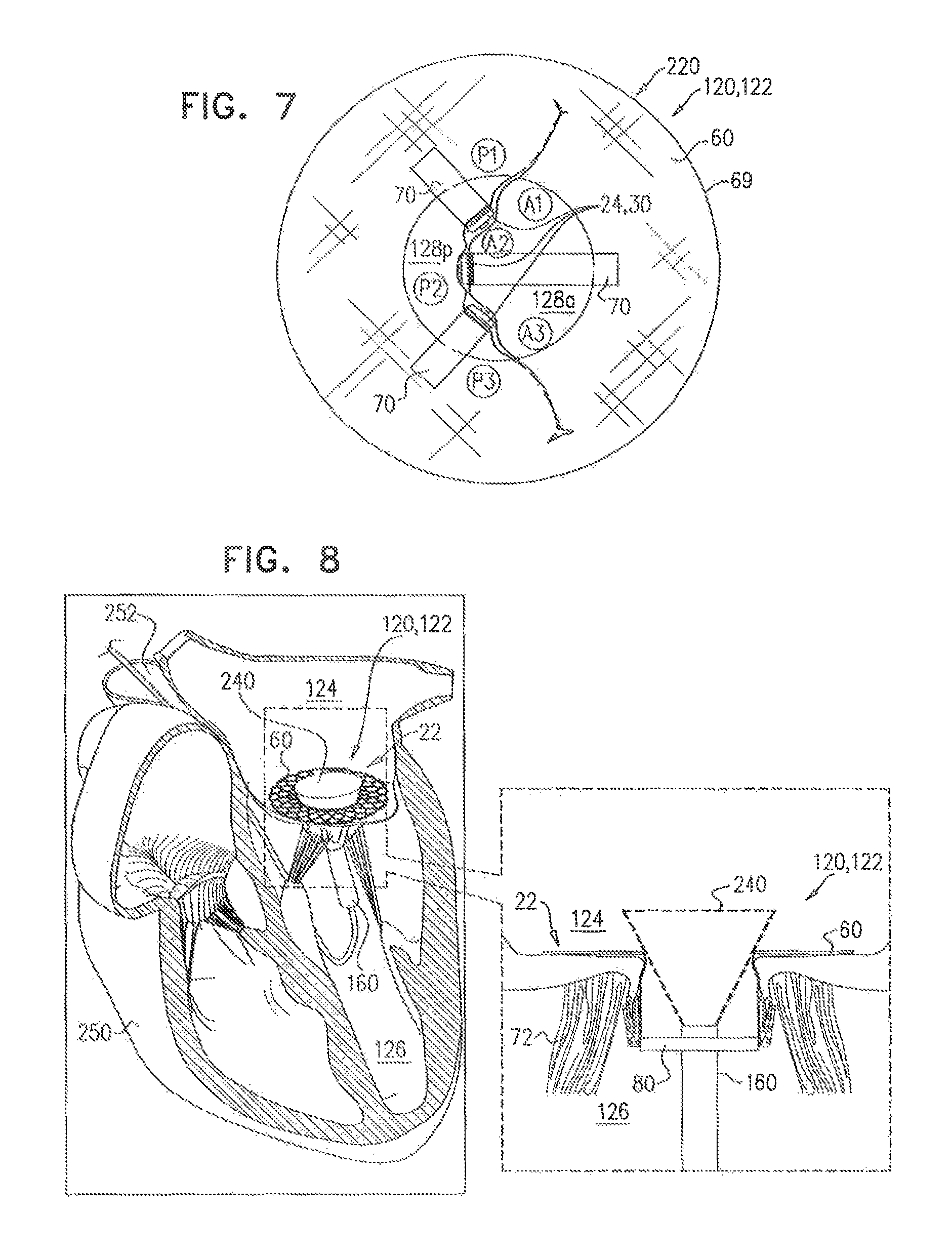
9. Apparatus for use at a native heart valve of a subject, the native heart valve including a native annulus and a plurality of native leaflets that provide check valve functionality, the apparatus comprising an implant configured to be transluminally-delivered to the native valve and to be deployed at the native valve, the implant comprising: one or more tissue-engaging elements, configured to be coupled to the native leaflets, and to couple the implant to the native leaflets without eliminating the check valve functionality, by holding together a portion of one of the native leaflets and a portion of another of the native leaflets such that the one leaflet and the other leaflet become arranged to define two orifices between the one leaflet and the other leaflet, each orifice configured to function as a respective check-valve; and an annular portion, configured to be secured against an upstream side of the native valve by the coupling of the one or more tissue-engaging elements to the native leaflets.
10. The apparatus according to claim 9, wherein the tissue-engaging elements comprise at least a first tissue-engaging element and a second tissue-engaging element, and wherein the first tissue-engaging element is transluminally controllable independently of the second tissue-engaging element.
11. The apparatus according to claim 9, wherein the implant comprises one or more flexible connectors, and wherein each tissue-engaging element is flexibly coupled to the annular portion by a respective flexible connector.
12. The apparatus according to claim 11, wherein each flexible connector has a length, and is configured such that the length is variable while the tissue-engaging elements are coupled to the native leaflets.
13. The apparatus according to claim 9, wherein the tissue-engaging elements comprise clips, each clip comprising a plurality of clip arms, comprising at least a first clip arm and a second clip arm, and configured to couple at least a portion of one of the native leaflets between the first and second clip arms.
14. The apparatus according to claim 13, further comprising a clip controller, configured to be advanced transluminally to the native valve, wherein each clip comprises a clip-controller interface, configured to be reversibly coupled to the clip controller, and to facilitate extracorporeal control of the clips independently of deployment of the implant.
15. The apparatus according to claim 14, wherein each clip is configured such that movement of at least a portion of the clip-controller interface by a first distance, changes a distance between a portion of the first clip arm and a portion of the second clip arm by a second distance that is more than 1.5 times greater than the first distance.
16. A method, comprising: using a delivery apparatus, transluminally advancing an implant to a native heart valve of a subject, the native valve including at least a first native leaflet and a second native leaflet, the implant including: an annular portion, being configured to be placed against an upstream side of the native valve, and having an inner perimeter that defines an opening, and at least one leaflet clip: (i) coupled to the annular portion, (ii) comprising: at least two clip arms, movable with respect to each other to open and close the clip; and a clip-controller interface, the clip-controller interface being coupled to at least one of the clip arms, and (iii) configured: to be coupled to a portion of the first native leaflet by the clip arms being brought together to close around the first native leaflet, to be coupled to a portion of the second native leaflet by the clip arms being brought together to close around the second native leaflet, and to hold together the portion of the first leaflet and the portion of the second leaflet; and placing the annular portion of the implant against the upstream surface of the native heart valve; using a clip controller of the delivery apparatus, securing the annular portion against the upstream surface by coupling the at least one leaflet clip to the portion of the first native leaflet and to the portion of the second native leaflet such that the at least one leaflet clip holds together the portion of the first native leaflet and the portion of the second native leaflet, the clip controller being reversibly couplable to the clip-controller interface, and configured to facilitate opening and closing of the clip; and subsequently, intracorporeally decoupling the delivery apparatus from the implant.
17. The method according to claim 16, wherein coupling the at least one leaflet clip to the portion of the first native leaflet and to the portion of the second native leaflet comprises using the at least one leaflet clip to arrange the first native leaflet and the second native leaflet to define two orifices between the first native leaflet and the second native leaflet, each orifice configured to function as a respective check-valve.
18. The apparatus according to claim 1, wherein the clip is configured such that opening and closing of the clip comprises changing a relative angular disposition between the clip arms.
19. The apparatus according to claim 1, wherein: the annular portion has a compressed configuration and an expanded configuration, while the annular portion is in the compressed configuration, the implant is transluminally deliverable, by the delivery apparatus, into the subject, and the annular portion is configured to automatically expand into an expanded configuration upon intracorporeal deployment of the annular portion from the delivery apparatus.
20. The apparatus according to claim 1, wherein each leaflet clip further comprises a tissue-engaging portion articulatably coupled to one of the clip arms of the leaflet clip, and facing another one of the clip arms of the leaflet clip.
21. The apparatus according to claim 1, wherein the annular portion is generally flat.
Description
FIELD OF THE INVENTION
Some applications of the present invention relate in general to valve replacement. More specifically, some applications of the present invention relate to prosthetic valves for replacement of a cardiac valve.
BACKGROUND
Ischemic heart disease causes regurgitation of a heart valve by the combination of ischemic dysfunction of the papillary muscles, and the dilatation of the ventricle that is present in ischemic heart disease, with the subsequent displacement of the papillary muscles and the dilatation of the valve annulus.
Dilation of the annulus of the valve prevents the valve leaflets from fully coapting when the valve is closed. Regurgitation of blood from the ventricle into the atrium results in increased total stroke volume and decreased cardiac output, and ultimate weakening of the ventricle secondary to a volume overload and a pressure overload of the atrium.
SUMMARY OF THE INVENTION
For some applications of the invention, a prosthetic valve support is provided for facilitating minimally invasive (e.g., transcatheter and/or transluminal) implantation of a prosthetic valve at a native valve of a subject. The native valve typically has native check valve functionality, i.e., it functions as a check valve. It is understood that a diseased valve has sub-optimal native check valve functionality, however the term "check valve functionality," as used in the context of the specification and in the claims, when used with respect to a native valve, refers to the native level of check valve functionality of the native valve. The prosthetic valve support is typically couplable to the native valve (e.g., to leaflets thereof) of the subject without eliminating the check valve functionality of the native valve. The prosthetic valve is subsequently implanted at the native valve by coupling the prosthetic valve to the prosthetic valve support, typically by expanding the prosthetic valve within one or more openings defined by the prosthetic valve support. The implantation of the prosthetic valve at the native valve replaces, at least in part, the check valve functionality of the native valve with substitute check valve functionality of the prosthetic valve. The prosthetic valve support comprises tissue-engaging elements, such as clips. Typically, but not necessarily, the prosthetic valve support further comprises (1) an upstream support portion, configured to be placed against an upstream surface of the native valve, and shaped to define one of the openings, and (2) a stabilizing element, shaped to define another of the openings.
For some applications, the prosthetic valve support is configured to be coupled to the native valve (e.g., to leaflets thereof) without eliminating the check valve functionality of the native valve, by allowing (1) the native leaflets to define a single orifice, and (2) the native valve to function as a single check valve (e.g., to function in a manner that is generally similar to the natural (e.g., physiological) function of the native valve). For some applications, the prosthetic valve support is configured to be coupled to the native valve (e.g., to leaflets thereof) without eliminating the check valve functionality by coupling together respective portions of two leaflets, such that (1) the native leaflets define two orifices, and (2) the native valve functions as two (e.g., parallel) check valves.
For some applications, it is hypothesized that the use of a two-component implant (i.e., comprising the prosthetic valve support and a separate prosthetic valve), advantageously facilitates delivery of the prosthetic valve via a catheter narrower than 28 Fr (e.g., by allowing the use of a `minimalistic` prosthetic valve, such as a prosthetic valve with few or no appendages).
For some applications, it is hypothesized that the use of a prosthetic valve support that does not eliminate check valve functionality of the native valve, facilitates the separate delivery of the prosthetic valve support and the prosthetic valve (i.e., a two-stage delivery), and thereby further facilitates the use of a narrow catheter.
For some applications, it is further hypothesized that the use of the prosthetic valve support enhances the check valve functionality of the native valve, and thereby provides both (1) "repair" of the native valve, and (2) an implantation site that is pre-prepared for subsequent implantation of a prosthetic valve at a later date, should such implantation be subsequently considered necessary.
There is therefore provided, in accordance with an application of the present invention, apparatus for use with a prosthetic valve for implantation at a native valve of a subject, the native valve including at least one native leaflet, the apparatus including:
a prosthetic valve support, including: an upstream support portion, being configured to be placed against an upstream side of the native valve, and having an inner perimeter that defines an opening that is configured to receive the prosthetic valve, and at least one clip: including at least two clip arms and a clip-controller interface, the clip-controller interface being coupled to at least one of the clip arms, and being configured to be coupled to a native leaflet of the native valve; and
at least one clip controller, reversibly couplable to the clip-controller interface, and configured to facilitate opening and closing of the clip.
In an application, the at least two clip arms include a first clip arm, configured to be disposed against an upstream surface of the leaflet, and a second clip arm, configured to be disposed against a downstream surface of the leaflet.
In an application, the clip controller is configured to facilitate opening and closing of the clip irrespective of a state of expansion of the prosthetic valve support.
In an application, the at least one clip includes at least a first clip and a second clip, and the second clip is openable and closeable independently of the first clip.
In an application, the at least one clip includes at least a first clip and a second clip, and the first clip is fixedly coupled to the second clip, and is configured to be decoupled from the second clip.
In an application, the at least one clip is configured to be coupled to a single native leaflet of the native valve.
In an application, the at least one clip is configured to be lockable such that the first clip arm is locked with respect to the second clip arm.
In an application:
the native valve includes at least a first native leaflet and a second native leaflet,
the at least one clip includes at least a first clip and a second clip, the first clip being configured to be coupled to the first leaflet, and the second clip being configured to be coupled to the second leaflet, and
the prosthetic valve support is configured such that, when (1) the upstream support portion is disposed against the upstream side of the native valve, (2) the first clip is coupled to the first leaflet, and (3) the second clip is coupled to the second leaflet, the first clip moves toward the second clip during ventricular systole of the subject, and moves away from the second clip during ventricular diastole of the subject.
In an application, the clip is flexibly coupled to the upstream support portion.
In an application, the clip is coupled to the upstream support portion via a flexible connector, the flexible connector having a length from the upstream support portion to the clip, and the length of the flexible connector is variable.
In an application, the upstream support portion is generally flat.
In an application, the inner perimeter defines the opening, such that the opening has a depth and a width, and the width of the opening is more than four times greater than the depth of the opening.
In an application, the upstream support portion has a free inner edge, and the free inner edge defines the inner perimeter.
In an application, the inner perimeter defines an opening that has a diameter, and the upstream support portion has a diameter that is at least 10 percent greater than the diameter of the opening.
In an application, no part of the prosthetic valve support that circumscribes a space that has a perimeter greater than 60 mm has a height of more than 20 mm.
There is further provided, in accordance with an application of the present invention, apparatus for facilitating implantation of a prosthetic valve at a native heart valve of a subject, the native heart valve including a native annulus and a plurality of native leaflets that provide check valve functionality, the apparatus including a prosthetic valve support, the prosthetic valve support:
being configured to be transluminally-delivered to the native valve and to be deployed at the native valve, and
including one or more tissue-engaging elements, configured to couple the prosthetic valve support to the native leaflets without eliminating the check valve functionality.
In an application, the tissue-engaging elements are configured to couple the prosthetic valve support to the native leaflets without eliminating the check valve functionality, by coupling the prosthetic valve support to the native leaflets such that:
the native leaflets define a single orifice therebetween, and
the native valve functions as a single check valve.
In an application, the tissue-engaging elements include at least a first tissue-engaging element and a second tissue-engaging element, and the first tissue-engaging element is transluminally controllable independently of the second tissue-engaging element.
In an application, the tissue-engaging elements are configured to couple the prosthetic valve support to the native leaflets without eliminating the check valve functionality, by coupling the prosthetic valve support to the native leaflets such that:
the native leaflets define two orifices therebetween, and
the native valve functions as two check valves.
In an application:
the native leaflets include a first leaflet and a second leaflet,
the tissue-engaging elements include at least a first tissue-engaging element and a second tissue-engaging element,
the first tissue-engaging element is configured to be coupled to a portion of the first leaflet, and
the second tissue-engaging element is configured to be coupled to a portion of the second leaflet and to the first tissue-engaging element.
In an application, the apparatus is configured such that the first tissue-engaging element is transluminally, intracorporeally decouplable from the second tissue-engaging element.
In an application, the prosthetic valve support includes an annular upstream support portion:
shaped to define an opening therethrough,
coupled to the tissue-engaging elements,
configured to be placed against an upstream surface of the native annulus, and
configured to be transluminally, intracorporeally, coupled to the prosthetic valve.
In an application, the apparatus further includes the prosthetic valve, and the prosthetic valve includes a flexible netting at at least an upstream portion of the prosthetic valve, and the netting is configured to facilitate coupling of the prosthetic valve to the upstream support portion.
In an application, the prosthetic valve support includes one or more flexible connectors, and each tissue-engaging element is flexibly coupled to the upstream support portion by a respective flexible connector.
In an application, each flexible connector has a length, and is configured such that the length is variable while the tissue-engaging elements are coupled to the native leaflets.
In an application, the upstream support portion has a compressed configuration and an expanded configuration, and is configured (1) to be delivered to the native valve in the compressed configuration, and (2) to be expanded into the expanded configuration at the native valve.
In an application, the apparatus further includes one or more coupling leads, and the apparatus is configured such that the expansion of the upstream support portion is controllable using the coupling leads.
In an application, each coupling lead passes around at least a portion of the upstream support portion, and the apparatus is configured such that the upstream support portion is recompressible from the expanded configuration toward the compressed configuration, by pulling on the coupling leads.
In an application, the prosthetic valve support includes a downstream stabilizing element:
shaped to define an opening therethrough,
coupled to the tissue-engaging elements,
configured to be placed entirely downstream of the native annulus, and
configured to be coupled to the prosthetic valve.
In an application, the apparatus further includes the prosthetic valve, and the prosthetic valve includes a valve body and one or more valve-anchoring elements, the valve-anchoring elements being configured to sandwich the downstream stabilizing element between the valve-anchoring elements and the valve body.
In an application, the prosthetic valve support is configured to be coupled to the native leaflets such that no portion of the prosthetic valve support is disposed upstream of the native annulus.
In an application, the tissue-engaging elements include clips, each clip including a plurality of clip arms, including at least a first clip arm and a second clip arm, and configured to couple at least a portion of one of the native leaflets between the first and second clip arms.
In an application, the apparatus further includes a clip controller, configured to be advanced transluminally to the native valve, and each clip includes a clip-controller interface, configured to be reversibly coupled to the clip controller, and to facilitate extracorporeal control of the clips independently of deployment of the prosthetic valve support.
In an application, each clip is configured such that movement of at least a portion of the clip-controller interface by a first distance, changes a distance between a portion of the first clip arm and a portion of the second clip arm by a second distance that is more than 1.5 times greater than the first distance.
In an application, the tissue-engaging elements are configured to suturelessly couple the prosthetic valve support to the native leaflets.
In an application, the prosthetic valve support is configured to be transluminally, intracorporeally, couplable to the prosthetic valve.
There is further provided, in accordance with an application of the present invention, a method for use at a native valve of a subject, the native valve including at least one native leaflet that provides native check valve functionality, the method including:
transluminally delivering a prosthetic valve support to the native valve;
coupling a prosthetic valve support to the leaflet of the native valve without eliminating the native check valve functionality; and
subsequently, replacing, at least in part, the native check valve functionality with a substitute check valve functionality, by coupling a prosthetic valve to the prosthetic valve support.
In an application:
the prosthetic valve support includes at least one clip,
the clip includes two or more clip arms and a clip-controller interface, and
coupling the prosthetic valve support to the leaflet includes changing an angular disposition between the clip arms by moving the clip-controller interface.
There is further provided, in accordance with an application of the present invention, apparatus for use with a native heart valve of a subject, the apparatus including:
a first expandable prosthetic valve component, including a crimpable frame, and configured to be transcatheterally advanceable toward the native valve while the first prosthetic valve component is in a crimped state thereof;
a second expandable prosthetic valve component, including a crimpable frame, and configured to be transcatheterally advanceable toward the native valve, placeable in the native valve while the second prosthetic valve component is in a crimped state thereof, and couplable to the first prosthetic valve component, expansion of the second prosthetic valve component facilitating coupling of the second prosthetic valve component to the first prosthetic valve component; and
one or more tissue-engagement elements, coupled to at least one of the prosthetic valve components, the tissue-engagement elements configured, when the prosthetic valve component is in an expanded state thereof, to extend from the prosthetic valve component, and to inhibit a proximal movement of the prosthetic valve component.
There is further provided, in accordance with an application of the present invention, apparatus for use with a prosthetic valve for implantation at a native valve of a subject, the native valve (1) defining an orifice, (2) including at least one native leaflet, having a native beating, and (3) baying a native blood flow regulation functionality, the apparatus including:
a prosthetic valve support, including: an upstream support portion, configured to be placed against an upstream side of the native valve, to have an inner perimeter that defines an opening that is configured to receive the prosthetic valve, and at least one clip, configured to be coupled to a native leaflet of the native valve, the clip including a plurality of clip arms, at least one clip arm coupled to a clip-controller interface; and a clip controller, couplable to the clip-controller interface, and configured to control a relative angular disposition between the clip arms.
For some applications, techniques described herein are practiced in combination with techniques described in one or more of the references cited in the Background section and Cross-references section of the present patent application.
BRIEF DESCRIPTION OF THE DRAWINGS
FIGS. 1A-D are schematic illustrations of apparatus, comprising a prosthetic valve support, for facilitating implantation of a prosthetic heart valve at a native heart valve of a subject, in accordance with some applications of the invention;
FIGS. 2A-D are schematic illustrations of the prosthetic valve support, and components thereof, in accordance with respective applications of the invention;
FIGS. 3A-I are schematic illustrations of steps in the delivery and implantation of the prosthetic valve support at the native heart valve of the subject, and the use thereof to facilitate implantation of the prosthetic valve, in accordance with some applications of the invention;
FIGS. 4A-F are schematic illustrations of a system for facilitating controlled expansion and/or retrievability of an upstream support portion of the prosthetic valve support, in accordance with some applications of the invention;
FIG. 5 is a schematic illustration of a step in the implantation of the prosthetic valve support, in accordance with some applications of the invention;
FIGS. 6A-B are schematic illustrations of a prosthetic valve support comprising tissue-engaging elements that are couplable to each other, and decouplable from each other, in accordance with some applications of the invention;
FIG. 7 is a schematic illustration of a prosthetic valve support comprising the upstream support portion and three clips, in accordance with some applications of the invention;
FIG. 8 is a schematic illustration of a step in the implantation of the prosthetic valve, facilitated by the prosthetic valve support, in accordance with some applications of the invention; and
FIGS. 9A-C are schematic illustrations of the prosthetic valve support comprising variable-length connectors, in accordance with respective applications of the invention.
DETAILED DESCRIPTION OF EMBODIMENTS
Reference is made to FIGS. 1A-D, which are schematic illustrations of apparatus 20, comprising a prosthetic valve support 22 for facilitating implantation of a prosthetic heart valve at a native heart valve of a subject, in accordance with some applications of the invention. Prosthetic valve support 22 comprises one or more tissue-engaging elements 24 (e.g., support-anchoring elements), and is typically configured to be coupled to the native heart valve (e.g., to leaflets thereof) without eliminating check valve functionality of the native heart valve (described in more detail hereinbelow). Typically, prosthetic valve 22 is configured to be transluminally, intracorporeally coupled to the native heart valve.
Typically, each tissue-engaging element 24 comprises a clip 30, which typically comprises a plurality of clip arms 32 (e.g., two clips arms, e.g., a first clip arm 32a and a second clip arm 32b), the clip being configured to be coupled to a leaflet of the native valve. Clip arms 32a and 32b are movable with respect to each other, thereby opening and closing clip 30 (e.g., moving clip 30 between an open state and a closed state thereof), e.g., as shown in FIG. 1B. Clip arms 32a and 32b are typically articulatably coupled to each other at an articulation point 31 (e.g., a coupling point), such that opening and closing clip 30 comprises changing a relative angular disposition between the clip arms. Typically, each clip arm 32 has a length from a first end thereof, at which the clip arms are coupled to each other (e.g., at articulation point 31), to a second end thereof, of greater than 1.5 mm and/or less than 20 mm (e.g., between 3 and 10 mm). For some applications, a length d7 of clip arm 32a is generally the same as a length d8 of clip arm 32b (e.g., as shown in FIG. 1B). For some applications, length d8 of clip arm 32b is shorter than length d7 of clip arm 32a (e.g., at least 30% shorter, such as at least 50% shorter), e.g., so as to reduce force applied to the leaflet of the native valve by clip arm 32b (such as by the second end of the clip arm).
For some applications of the invention, at least one of the clip arms (e.g., clip arm 32b) comprises a tissue-engaging portion 48 that is articulatably coupled to another portion of the clip arm at an articulation point 47, such that, at a given relative angular disposition of clip arms 32a and 32b (e.g., a degree of openness of clip 30), a relative angular disposition of portion 48 with respect to clip arm 32a, may change (e.g., may be changed). For example, for at least some states of clip 30, the relative angular disposition of clip arm 32a and portion 48 may be generally independent of the relative angular disposition of clip arm 32a and the other portion of clip arm 32b. For example, portion 48 may remain parallel with clip arm 32a, irrespective of the angular disposition of clip arms 32a and 32b. It is hypothesized that this configuration facilitates coupling of clip 30 to the leaflet of the native valve, by allowing the clip to maintain contact with both sides of the leaflet, irrespective of dimensions (e.g., thicknesses) of the leaflet to which clip 30 is coupled.
Prosthetic valve support 22 is typically configured to be implanted using minimally-invasive procedures (e.g., percutaneously). Further typically, the prosthetic valve support is configured to be delivered transluminally (e.g., transfemorally). Alternatively, the prosthetic valve support may be configured to be delivered transthoracically (e.g., transapically). Typically, the prosthetic valve support is configured in this way by being compressible (e.g., crimpable) into a delivery configuration, and by being configured to expand (e.g., automatically) upon deployment at the native valve. Typically, tissue-engaging elements 24 (e.g., clips 30) are coupled to the leaflets of the native valve before prosthetic valve support 22 is fully deployed, such as while at least part of the prosthetic valve support remains within a delivery tube (e.g., as shown in FIGS. 3B-C).
Clips 30 are typically configured to be controllable (i.e., openable and closable) independently of each other, and/or independently of deployment of prosthetic valve support 22 (e.g., irrespective of a state of deployment of the prosthetic valve support, such as irrespective of a state of expansion of an upstream support portion 60 of the prosthetic valve support, described hereinbelow).
Clip 30 typically further comprises a clip-controller interface 34, which is configured to facilitate control (e.g., opening and closing) of the clip from outside the subject (i.e., to facilitate extracorporeal control of the clip), e.g., by a physician. Clip-controller interface 34 is reversibly couplable to a clip controller 36, which is itself extracorporeally controllable, e.g., by extending from outside the subject to the clip-controller interface. Clip 30 is thereby typically transluminally controllable. Typically, clip controller 36 facilitates control of the clip by applying a force to clip-controller interface 34, e.g., by transferring an extracorporeally-applied force to the clip-controller interface. Typically, clip controller 36 is integral with delivery apparatus that is used to deliver support 22 to the native valve (e.g., delivery apparatus 140, described hereinbelow with reference to FIGS. 3A-D).
Clip-controller interface 34 is typically articulatably coupled to at least clip arm 32b (e.g., at an articulation point 35), and/or comprises one or more articulatably coupled portions (e.g., a first interface portion 34a and a second interface portion 34b). Clips 30 are typically configured such that movement of clip-controller interface 34 by a first distance d1, moves clip arm 32b by a second distance d2 that is typically more than 1.5 times (e.g., more than 2 times, such as more than 4 times) greater than distance d1. That is, a relatively large range of movement of clip arm 32b is provided by a relatively small range of movement of dip-controller interface 34, e.g., clip-controller interface 34, clip arm 32b, and/or the coupling therebetween, acts as a lever. Clip 30 is typically configured such that clip arm 32b can articulate over more than 60 degrees, e.g., more than 100 degrees, such as up to 180 degrees, around articulation point 31, with respect to clip arm 32a.
It is hypothesized that, for some applications, angles of articulation greater than 80 degrees (e.g., greater than 120 degrees, such as up to 180 degrees) facilitate (1) repeated coupling to, and decoupling from, the native leaflets (e.g., multiple attempts to couple to the native leaflets), and (2) retrieval of the clips and/or the entire prosthetic valve support (e.g., into a delivery tube).
Clip-controller interface 34 (e.g., portion 34a thereof) is typically slidably coupled to at least clip arm 32a. That is, moving of clip-controller interface 34 typically includes sliding of the clip-controller interface with respect to clip arm 32a (e.g., by using clip controller 36).
For some applications of the invention, at least one of clip arms 32 comprises or defines grips 38 and/or teeth 40, which are configured to facilitate coupling of clip 30 to a native leaflet of the native valve. Typically, grips 38 are configured to atraumatically grip the leaflet and teeth 40 are configured to grip, fold around, and/or pierce the leaflet. For some applications of the invention, at least a portion of clip arms 32 is covered with a padding (not shown), configured to cushion the contact between the clip arms and the leaflet.
Typically, clip 30 is lockable, such that clip arm 32b is locked (e.g., immobile) with respect to clip arm 32a. FIGS. 1B-D show clip 30 comprising a locking element 50 (e.g., a securing element), which facilitates locking of the clip. Locking element 50 typically comprises at least one ratchet mechanism 52, comprising (1) a rack 51, comprising a plurality of sockets 54, and (2) an engaging element 56 (e.g., a pawl, or a tooth). Typically, rack 51 is defined by, or is fixedly coupled to, clip arm 32a, and engaging element 56 is coupled to, or defined by, clip-controller interface 34. However, the scope of the invention includes other (e.g., inverse) arrangements of ratchet mechanism 52.
FIG. 1B shows clip 30 in an unlocked configuration thereof, in which an obstructing element 58 (e.g., a restraint) is disposed between rack 51 and engaging element 56, thereby inhibiting (e.g., obstructing) engaging element 56 from engaging rack 51, and thereby facilitating the opening and closing of the clip (i.e., movement between open and closed states thereof). Typically, obstructing element 58 is integral with delivery apparatus that is used to deliver support 22 to the native valve (e.g., delivery apparatus 140, described hereinbelow with reference to FIGS. 3A-D). FIG. 1B shows a front view and a back view of clip 30 in the open state thereof, and a front view and a back view of the clip in the closed state thereof.
FIG. 1C shows a back view of clip 30 in a locked configuration thereof, in which obstructing element 58 has been removed from between rack 51 and engaging element 56 (e.g., by withdrawing the obstructing element proximally), and an engaging element 56 has engaged the rack. Typically, element 56 is configured (e.g., shape-set) to automatically engage rack 51 upon removal of obstructing element 58.
For some applications, and as shown in FIGS. 1B-D, obstructing element 58 comprises a longitudinal member, such as a strip or rod, and is removed by being withdrawn proximally. However, obstructing element 58 may have other shapes and/or shape-memory features that facilitate the obstruction of engaging element 56 and/or the removal of the obstructing element. For example, obstructing element 58 may have a generally circular, rectangular, triangular, or hexagonal cross-section, and/or may be shape-set to facilitate removal thereof, and thereby to facilitate locking of the clip.
For some applications of the invention, and as shown in FIGS. 1B-D, locking element 50 comprises two ratchet mechanisms 52. The two ratchet mechanisms are offset with respect to the other, such that at a position of clip-controller interface 34 in which the engaging element 56 of one ratchet mechanism is fully disposed in a socket 54, the engaging element of the other ratchet mechanism is not fully disposed in a socket of the other rack (FIGS. 1C-D). This configuration increases (e.g., doubles) the number of positions within a given range in which clip-controller interface 34 is lockable, without reducing the size of each socket 54. That is, this configuration increases the "resolution" or "density" of locking positions of dip 30. It is hypothesized that, for some applications, it is advantageous to combine this configuration of locking element 50 with the lever-like clip-controller interface described hereinabove, such that the relatively large movement of clip arm 32b is at least partly offset by the "high resolution" of the locking element, thereby increasing the degree of control that the physician has on the clip.
As described hereinabove, clip-controller interface 34 is typically reversibly couplable to clip controller 36. Typically, this reversible coupling is facilitated by a projection 42, defined by clip controller 36, which is configured to be disposed within, and removed from, a depression 44, defined by clip-controller interface 34. Further typically, projection 42 is configured (e.g., shape-set) to move out from depression 44, and is prevented from moving out of depression 44 by obstructing element 58. Following the locking of dip 30 by withdrawing obstructing element 58 (FIG. 1C), the obstructing element is further withdrawn (FIG. 1D), thereby releasing projection 42 from depression 44, and thereby decoupling clip controller 36 from clip-controller interface 34. Clip 30 is typically configured such that the physician may repeatedly lock and unlock clip 30 (e.g., by partially withdrawing and replacing obstructing element 58) before finally decoupling the controller (e.g., by completely withdrawing obstructing element 58), such as after confirming that clip 30 has been successfully coupled to the native leaflet.
As described hereinabove, clips 30 are typically configured to be controllable (i.e., openable and closable) independently of each other, and/or independently of deployment of prosthetic valve support 22. Clips 30 are further typically lockable and/or decouplable from controller 36 independently of each other, and/or independently of deployment of the prosthetic valve support. It is to be noted that clips 30 are configured to couple the prosthetic valve support to the native leaflets suturelessly.
Referring again to FIG. 1A, prosthetic valve support 22 typically comprises a generally annular upstream support portion 60 (e.g., an annular portion), shaped to define an opening 61 (e.g., an aperture) therethrough, and to be placed against an upstream side of the native valve. Typically, upstream support portion 60 comprises an expandable lattice-structure frame 62 (e.g., comprising a plurality of struts), covered by a covering 64. Opening 61 is defined by an inner perimeter 68 of the prosthetic valve support. For some applications, frame 62 defines a plurality of barbs 67 that protrude radially inwardly from inner perimeter 68, and facilitate coupling of a prosthetic valve to the prosthetic valve support (e.g., as described hereinbelow with reference to FIGS. 3H-I).
Upstream support portion 60 typically has shape-memory (e.g., resilient, pseudoelastic and/or superelastic) properties. Typically, frame 62 comprises a shape-memory (e.g., resilient, pseudoelastic and/or superelastic) material, such that upstream support portion 60 is compressible (e.g., crimpable) when a compressive force is applied (e.g., prior to implantation), and re-expandable when the compressive force is removed (e.g., during implantation). Non-limiting examples of materials that frame 62 may comprise, include nickel-titanium (nitinol), stainless steel, nickel cobalt, cobalt chrome, titanium, tantalum, and palladium.
Non-limiting examples of materials that covering 64 may comprise, include polyethylene terephthalate (e.g., polyester), polytetrafluoroethylene (e.g., Teflon, ePTFE), and pericardial tissue. For some applications, covering 64 comprises a fabric. Typically, a thickness of the covering is less than 0.5 mm, such as less than 0.2 mm, e.g., less than 0.1 mm, or less than 0.05 mm.
FIG. 1A shows upstream support portion 60 in an expanded (e.g., fully uncompressed and/or deployed) configuration thereof, in which upstream support portion 60 (i.e., an outer perimeter 69 thereof) typically has a diameter d3 that is greater than 40 mm and/or less than 80 mm (e.g., 40-80 mm, such as 40-70 mm, such as 40-60 mm). That is, an outer diameter of upstream support portion 60 is typically greater than 40 mm and/or less than 80 mm (e.g., 40-80 mm, such as 40-70 mm, such as 40-60 mm). Opening 61, defined by inner perimeter 68, typically has a diameter d4 of greater than 20 mm and/or less than 35 mm (e.g., 20-35 mm, such as 23-32 mm, such as 25-30 mm). That is, an inner diameter of upstream support portion 60 is typically greater than 20 mm and/or less than 35 mm (e.g., 20-35 mm, such as 23-32 mm, such as 25-30 mm). Typically, diameter d3 is at least 10% (e.g., at least 50%, such as at least 80%) greater than diameter d4.
Upstream support portion 60 is typically compressible (e.g., crimpable; for delivery to the native valve) into a generally cylindrical shape in which inner perimeter 68 defines a downstream end 71 of the cylindrical shape, and outer perimeter 69 defines an upstream end 73 of the cylindrical shape (see FIG. 3A). Typically, the generally cylindrical shape of upstream support portion 60 has a transverse cross-sectional diameter (e.g., a width) of greater than 3 mm and/or less than 9 mm (e.g., 3-9 mm, such as 5-8 mm, such as 6-7 mm), and a height, from the upstream end to the downstream end, of greater than 11 mm and/or less than 30 mm (e.g., 11-30 mm, such as 15-30 mm, such as 15-25 mm).
In the expanded configuration thereof, upstream support portion 60 is typically (but not necessarily) generally flat (e.g., laminar, and/or planar). For some applications, in the expanded configuration, upstream support portion 60 assumes a frustoconical shape. Upstream support portion 60 typically has a thickness of less than 5 mm, e.g., less than 2 mm, such as between 0.3 mm and 2 mm. Inner perimeter 68 (and thereby opening 61) thereby typically has a depth d10 (e.g., a height) from an upstream side 59 of the upstream support portion to a downstream side 63 of the upstream support portion. Depth d10 is less than 5 mm, e.g., less than 2 mm, such as between 0.3 mm and 2 mm. Typically, diameter d4 of opening 61 is more than 4 times (e.g., more than 6 times, such as more than 10 times) greater than depth d10. That is, opening 61 is more than 4 times (e.g., more than 6 times, such as more than 10 times) wider than it is deep. Typically, in the expanded configuration, upstream support portion 60 has a total height of less than 10 mm (e.g., less than 5 mm, such as less than 2 mm).
Typically, inner perimeter 68 comprises, or is defined by, a free inner edge of upstream support portion 60. That is, opening 61 resembles a hole cut out of a lamina (e.g., out of a disc). For some applications, inner perimeter 68 comprises, or is defined by, a curved and/or folded inner edge of upstream support portion 60. If the inner perimeter of upstream support portion 60 comprises, or is defined by, a curved or folded edge, then a radius of curvature of the curved or folded edge is typically less than 2.5 mm, such as less than 1 mm. That is, the curve or fold of the edge is generally sharp, such that when viewed from within opening 61, the curved or folded edge looks generally like a free edge.
Prosthetic valve support 22 typically comprises two or more tissue-engaging elements 24 (e.g., clips 30), coupled to inner perimeter 68 of upstream support portion 60. For such applications, the two tissue-engaging elements are typically disposed opposite each other (e.g., at 180 degrees around inner perimeter 68 from each other).
Typically, tissue-engaging elements 24 (e.g., clips 30) are coupled to upstream support portion 60 (e.g., inner perimeter 68 thereof) by a flexible connector 70, which may comprise polyethylene terephthalate (e.g., polyester), polytetrafluoroethylene (e.g., Teflon, ePTFE), a fabric, nitinol, and/or any other suitable material. Thereby, tissue-engaging elements 24 (e.g., clips 30) are typically flexibly coupled to upstream support portion 60, and/or are able to move independently of each other. Connector 70 may be coupled to upstream support portion 60 and tissue-engaging elements 24 using sutures, welding, and/or any other suitable technique known in the art.
Prosthetic valve support 22 typically further comprises a stabilizing element 80, coupled to clips 30 (e.g., to a downstream portion thereof). Typically, stabilizing element 80 forms a ring shape that defines an opening 81 (e.g., an aperture), and is typically inelastic and at least partly flexible. Opening 81 typically, but not necessarily, has a diameter that is generally equal to diameter d4 of opening 61. Non-limiting examples of materials that stabilizing element 80 may comprise include polyethylene terephthalate (e.g., polyester), PTFE (e.g., ePTFE), nylon, cotton, nitinol, stainless steel, nickel cobalt, cobalt chrome, titanium, tantalum and palladium. Typically, and as shown in FIG. 1A, stabilizing element 80 comprises (1) an outer coat 82 of a flexible material (e.g., polyester), which typically provides inelasticity, and (2) an inner strip 84 of a shape-memory material (e.g., nitinol), which is typically configured (e.g., shape-set) to bias element 80 to assume a ring-shaped configuration.
Stabilizing element 80 (and thereby opening 81) typically has a depth d11 (e.g., a height from a most upstream part to a most downstream part) of less than 20 mm (e.g., less than 10 mm, e.g., less than 5 mm, such as less than 1 mm). As described hereinabove, inner perimeter 68 of upstream support portion has a depth d10 of less than 5 mm. Typically, in the expanded configuration, no part of prosthetic valve support 22 that circumscribes a space that has a perimeter greater than 60 mm (e.g., as upstream support portion 60 and stabilizing element 80 typically do) has a height of more than 20 mm. For some applications, in the expanded configuration, no part of the support that circumscribes a space that has a perimeter greater than 60 mm has a height of more than 10 mm. For some applications, in the expanded configuration, no part of the support that circumscribes a space that has a perimeter greater than 60 mm has a height of more than 5 mm.
Reference is made to FIGS. 2A-D, which are schematic illustrations of prosthetic valve support 22 and/or components thereof, in accordance with respective applications of the invention. As described hereinabove, upstream support portion 60 is generally annular. For some applications, and as shown in FIG. 1A, upstream support portion 60 has a generally circular outer perimeter 69. FIG. 2A shows an alternative embodiment in which upstream support portion 60 comprises an upstream support portion 90, which has a non-circular outer perimeter 99. FIG. 2A shows outer perimeter 99 as generally oval, with a "squashed" portion 92. Such a configuration may, for example, facilitate placement of upstream support portion 90 at a mitral valve of the subject, with squashed portion 92 facing the interatrial septum. It is to be noted, that the scope of the invention includes upstream support portions having other shapes, configured according to the anatomical site at which they are to be placed. For example, for some applications, upstream support portion 60 and/or upstream support portion 90 may have radially-protruding bulges or wings (not shown), configured to stabilize the upstream support portion and/or to inhibit leakage between the native valve and the upstream support portion.
As described hereinabove, upstream support portion 60 typically comprises an expandable lattice-structure frame 62. FIG. 2B shows an alternative embodiment in which to upstream support portion 60 comprises a braided upstream support portion 100, which comprises a braided structure of intertwining strands 102, at least some of which are slidable past (e.g., over, under) each other. Typically, strands 102 comprise a shape-memory material such as, but not limited to, nitinol. Upstream support portion 100 is transluminally deliverable in a compressed configuration, and is expandable to an annular, expanded configuration at the native valve. Typically, support 100 is configured to automatically expand to the expanded configuration, and this expansion is controlled by progressively releasing (e.g., loosening and/or unthreading) a restricting element 104 (e.g., a drawstring), which, when threaded through parts of upstream support portion 100 (e.g., one or more rings 106 thereof), is configured to restrict expansion of the upstream support portion (e.g., to retain the upstream support portion in the compressed configuration thereof). FIG. 2B shows sequential stages in the deployment of upstream support portion 100 from a delivery tube 108. Typically, upstream support portion 100 is recompressible by tightening (e.g., pulling) the restricting element.
As described hereinabove, prosthetic valve support 22 comprises one or more tissue-engaging elements 24, and typically further comprises upstream support portion 60 and/or stabilizing element 80. FIG. 1A shows prosthetic valve support 22 comprising both upstream support portion 60 and stabilizing element 80. FIG. 2C shows an alternative embodiment in which prosthetic valve support 22 comprises a prosthetic valve support 322, which does not comprise stabilizing element 80. FIG. 2D shows an alternative embodiment in which prosthetic valve support 22 comprises a prosthetic valve support 422, which does not comprise an upstream support portion (e.g., upstream support portion 60). For some applications of the invention, when implanted at the native valve, no portion of prosthetic valve support 422 is disposed upstream of the native annulus.
It is to be noted that upstream support portions 90 and 100, and prosthetic valve supports 322 and 422, may be used (e.g., combined) with apparatus and methods described elsewhere herein. For example, the upstream support portion of any of the prosthetic valve supports described herein may be replaced with upstream support portion 90 or upstream support portion 100, resulting in alternative prosthetic valve supports. Furthermore, these resulting prosthetic valve supports, as well as prosthetic valve supports 322 and 422, may be used in combination with other techniques described herein (e.g., with reference to FIGS. 3A-I, 4A-F, 5, 6A-B, 7, 8, and/or 9A-C), mutatis mutandis.
Reference is made to FIGS. 3A-I, which are schematic illustrations of steps in the delivery and implantation of prosthetic valve support 22 at a native heart valve 120 of heart 250 of a subject, and the use thereof to facilitate implantation of a prosthetic valve 150, in accordance with some applications of the invention. FIGS. 3A-I show native valve 120 as comprising a mitral valve 122 of the subject, but it is to be noted that the scope of the invention includes the use of prosthetic valve support 22 at other heart valves of the subject.
Mitral valve 122 is disposed between a left atrium 124 and a left ventricle 126 of the subject, and comprises two leaflets 128. Atrium 124 is upstream of mitral valve 122 and ventricle 126 is downstream of the mitral valve. Prosthetic valve support 22, in a compressed configuration thereof, is advanced transluminally (e.g., transfemorally and/or transseptally) within a delivery tube 130 of delivery apparatus 140, to atrium 124, and between leaflets 128 (FIG. 3A).
Prosthetic valve support 22 is advanced out of delivery tube 130 and/or the delivery tube is withdrawn from the prosthetic valve support (FIG. 3B). Clips 30 (and/or other tissue-engaging elements) are typically disposed at a downstream portion of prosthetic valve support 22 (e.g., downstream of downstream end 71 of upstream support portion 60) in the compressed configuration thereof, and are thereby exposed from delivery tube 130. Stabilizing element 80 is also typically exposed from the delivery tube, and typically forms a generally lemniscate (e.g., FIG. 8) shape, defining two "loops" 83. Typically, the axis between loops 83 of the lemniscate is generally orthogonal to the axis between clips 30, and may be used to orient prosthetic valve support 22, e.g., such that clips 30 point toward leaflets 128 of the native valve. For example, loops 83 may be disposed between chordae tendineae 72 of one leaflet and those of the other leaflet, and physical contact between the chordae tendineae and the loops automatically and/or via tactile feedback to the physician, facilitates orientation of the prosthetic valve support. Alternatively or additionally, the lemniscate shape of stabilizing element 80 may be visualized using imaging techniques such as fluoroscopy and/or ultrasound. Clips 30 are opened (e.g., as described hereinabove with reference to FIG. 1B).
Prosthetic valve support 60 is moved upstream (e.g., proximally) so as to envelope leaflets 128 between clip arms 32 of each clip 30, and each clip is closed around a leaflet, thereby coupling each clip to a leaflet, e.g., by clamping the leaflet between the clip arms (FIG. 3C). Each clip 30 couples to a single leaflet 128, such that one clip arm of each clip (e.g., clip arm 32a) engages an upstream surface of the leaflet (e.g., an upstream side of the leaflet), and the other clip arm of each clip (e.g., clip arm 32b) engages a downstream surface of the leaflet (e.g., a downstream side of the leaflet). Although each clip typically couples to only one leaflet, for some applications, more than one clip couples to each leaflet.
As described hereinabove, clips 30 (and/or other tissue-engaging elements 24) are typically coupled to the leaflets of the native valve before prosthetic valve support 22 is fully deployed. Clips 30 are typically locked (e.g., as described with reference to FIG. 1C), and subsequently decoupled from clip controller 36 (e.g., as described with reference to FIG. 1D). FIGS. 3C-F show stages in the deployment of prosthetic valve support 22 (e.g., of upstream support portion 60 thereof). Upstream support portion 60 typically progressively expands as it is exposed from delivery tube 130. Thereby, typically, (1) downstream end 71 of the cylindrical shape of the upstream support portion in the compressed configuration thereof, expands to become inner perimeter 68 of the upstream support portion in the expanded configuration thereof, and (2) subsequently, upstream end 73 of the cylindrical shape expands to become outer perimeter 69 of the upstream support portion.
Delivery apparatus 140 typically comprises a pushing member 132. Typically, prosthetic valve support 22 (e.g., upstream support portion 60 thereof) is reversibly coupled to pushing member 132, and is exposed from delivery tube 130 by being pushed using the pushing member. Upstream support portion 60 is typically configured (e.g., shape-set) to automatically expand toward its expanded configuration upon being deployed from delivery tube 130. For some applications of the invention, the upstream support portion "pops" open from the configuration shown in FIG. 3C to the configuration shown in FIG. 3F, immediately upon exposure of upstream end 73 of the upstream support portion from delivery tube 130.
For some applications, and as shown in FIGS. 3C-F, one or more holding members 134, coupled to, and decouplable from, upstream support portion 60, facilitate controlled expansion of the upstream support portion. For example, holding members 134 may be configured to allow a physician (1) to expand some portions of the upstream support portion before other portions and/or (2) to adjust the positioning of the upstream support portion on the upstream surface of the native valve following expansion of the upstream support portion. For some applications, two holding members 134 are used, and are coupled to opposite sides of upstream support portion 60 to each other (e.g., 180 degrees around the upstream support portion from each other).
For some applications, and as shown in FIGS. 3D-F, three holding members 134 are used. For such applications, each holding member 134 is coupled at between 90 and 180 degrees (e.g., between 100 and 150 degrees, such as at 120 degrees) around the upstream support portion from the other holding members. For some such applications, and as shown in FIG. 3F, the holding members are coupled to the upstream support portion such that, when the upstream support portion is positioned at the native valve, two holding members are disposed generally above respective commissures of the native valve, and the third holding member is disposed generally midway around posterior leaflet 128p of the native valve.
For some applications, holding members 134 comprise locking elements and/or coupling leads (e.g., coupling wires, e.g., looped around respective portions of the upstream support portion; not shown in FIGS. 3D-F) that couple the holding members to the upstream support portion, and the holding members are decoupled from the upstream support portion by unlocking the locking elements and/or unlooping the loops. For some applications of the invention, holding members 134 also facilitate retrieval of the upstream support portion, and thereby of prosthetic valve support 22, e.g., as described with reference to FIGS. 4A-F.
FIG. 3G shows prosthetic valve support 22 following coupling, deployment and expansion (i.e., implantation) thereof at mitral valve 122, and withdrawal of delivery apparatus 140. As described hereinabove, prosthetic valve support 22 is configured to be coupled to the native heart valve (e.g., to leaflets thereof) without eliminating check valve functionality of the native heart valve. Typically, and as shown in FIG. 3G, clips 30 couple the prosthetic valve support to leaflets 128 such that (1) the leaflets define a single orifice, and (2) the native valve functions as a single check valve (e.g., functions in a manner that is generally similar to the natural (e.g., physiological) function of the native valve). Stabilizing element 80 is also configured to allow such movement of leaflets 128. e.g., the stabilizing element is sufficiently flexible to flex in response to the leaflets moving in response to pumping of the heart. FIG. 3G shows (1) in solid, mitral valve 122 (e.g., leaflets 128) closed, and the respective state of prosthetic valve support 22, and (2) in phantom, the mitral valve (e.g., the leaflets) open, and the respective state of the prosthetic valve support.
Thereby, when prosthetic valve support 22 is implanted at an atrioventricular valve of the subject (e.g., mitral valve 122 or a tricuspid valve), clips 30 typically move away from each other during ventricular diastole, and toward each other during ventricular systole. For applications in which prosthetic valve support 22 is implanted at a native semilunar valve of the subject (e.g., an aortic valve or a pulmonary valve), clips 30 typically move toward each other during ventricular diastole, and away from each other during ventricular systole.
Subsequently (e.g., immediately subsequently, or after more than a minute, e.g., after more than 2 minutes, e.g., after more than 5 minutes, such as after more than an hour), a prosthetic valve 150 is transluminally delivered, in a compressed configuration thereof (e.g., within a delivery tube 160), to the native valve, and implanted at the native valve by coupling the prosthetic valve to prosthetic valve support 22. Implantation of prosthetic valve 150 replaces check valve functionality of the native valve with a substitute check valve functionality of the prosthetic valve. The substitute check valve functionality is provided by one or more prosthetic check valve elements (e.g., valve members, such as leaflets, a ball, or a disc), such as those known in the art, which the prosthetic valve comprises (not shown).
Typically, and as shown in FIG. 3H, respective portions of prosthetic valve 150 are placed within opening 61 (defined by upstream support portion 60) and/or opening 81 (defined by stabilizing element 80), and are expanded such that the respective portions engage the upstream support portion and the stabilizing element, respectively. Typically, prosthetic valve 150 is configured to automatically expand upon deployment from delivery tube 160, and radially-expansive force applied by prosthetic valve 150 to upstream support portion 60 and/or stabilizing element 80 facilitates coupling of the prosthetic valve to prosthetic valve support 22.
FIG. 3I shows prosthetic valve 150 having been fully deployed and coupled to prosthetic valve support 22. That is, FIG. 3I shows an implant 180, comprising prosthetic valve support 22 and prosthetic valve 150, having been implanted at native valve 120 (e.g., at mitral valve 122). Prosthetic valve 150 is described in more detail hereinbelow.
Typically, diameter d3 of upstream support portion 60 is greater than a diameter d5 of the native valve (e.g., a diameter of the orifice of the native valve, e.g., an inner diameter of the annulus of the native valve). Further typically, diameter d4 of opening 61 is smaller than diameter d5. When prosthetic valve 150 is expanded within opening 61 of the upstream support portion, a diameter d6 of the prosthetic valve is typically restricted by the upstream support portion to the same diameter as diameter d4 of opening 61. For some applications, contact between prosthetic valve 150 and upstream support portion 60 (e.g., resulting from the radially-expansive force of the valve on the support) couples the prosthetic valve to the prosthetic valve support, and/or inhibits retrograde leakage of blood therebetween.
When implanted at the native valve (e.g., when in respective expanded configurations), a height d9 of prosthetic valve 150 is typically at least 1.5 times greater (e.g., at least 3 times greater, such as at least 5 times greater) than the total height of upstream support portion 60. Typically, height d9 is at least 1.5 times greater (e.g., at least 3 times greater, such as at least 5 times greater) than depth d10 of opening 61.
As described hereinabove, upstream support portion 60 is configured to be placed against an upstream side of the native valve. It should be noted, that radial expansion of prosthetic valve 150 against inner perimeter 68 of upstream support portion 60, thereby typically does not cause the prosthetic valve support to apply a radially-expansive force to the native valve annulus. For some applications of the invention, this expansion of prosthetic valve 150 does not cause the prosthetic valve support to apply the radially-expansive force to the native valve annulus because no part of the prosthetic valve support that circumscribes the prosthetic valve is sandwiched between the prosthetic valve and the native valve annulus.
For some applications, prosthetic valve 150 is couplable to upstream support portion 60 at a plurality of positions along the length of the prosthetic valve. That is, a physician can couple the prosthetic valve at a plurality of depths within the support. For some applications, the prosthetic valve is couplable to the upstream support portion at a continuum of positions along the length of the prosthetic valve. That is, a physician can couple the prosthetic valve to the support at a continuum of depths within the support. For example, in some applications in which the prosthetic valve is configured to be coupled to the upstream support portion solely by the radially-expansive force, the prosthetic valve may be coupled to the upstream support portion at a continuum of positions along the length of the prosthetic valve.
For some applications, sealing between implant 180 and native valve 120 is facilitated by native leaflets 128 being pushed closed against the outer surface of the frame of the valve during systole, in a manner similar to that in which native valve leaflets of a healthy native valve coapt during systole.
For applications in which diameters d4 and d6 are relatively large, the proportion (e.g., the surface area) of the native leaflets that is pushed against the outer surface of the valve during systole is relatively large, thereby enhancing the sealing of the native leaflets with respect to the frame of the prosthetic valve. However, for some applications, beyond a given size, as diameters d4 and d6 increase, the native valve leaflets are pushed apart at the commissures, thereby potentially increasing a likelihood of paravalvular retrograde leakage of blood at the commissures. Therefore, for some applications of the present invention, prosthetic valve support 22 (and, typically, prosthetic valve 150) are selected such that diameters d4 and d6 are less than 90% (e.g., 5 less than 80%, e.g., less than 60%, such as less than 50%) of diameter d5 of the native valve (e.g., of the orifice of the native valve). Thus prosthetic valve support 22 facilitates sealing of the prosthetic valve with respect to the native valve, by facilitating closing of the native valve leaflets around the outer surface of the prosthetic valve.
In experiments conducted by the inventors, a prosthetic valve support 22 was implanted in two pigs. Both animals remained alive and stable (e.g., were hemodynamically stable, and had stable breathing rate and oxygen saturation) for a duration of sufficient length to withdraw delivery apparatus 140, introduce a valve-delivery system, and deploy (e.g., implant) a prosthetic valve in opening 61 of the support. The period between implanting prosthetic valve support 22 and implanting the prosthetic valve was between 5 and 10 minutes. During this duration, the native valve of the animals functioned generally normally. For example, native leaflet movement and coaptation, and blood flow therebetween was generally normal during this duration.
It is thereby hypothesized that, following implantation of prosthetic valve support 22, the heart of the subject is able to continue pumping blood sufficiently to support the subject (e.g., to maintain hemodynamic stability) for longer than a minute, e.g., longer than 2 minutes, e.g., longer than 5 minutes, such as longer than an hour. It is thereby hypothesized that a period of generally normal physiological activity of the subject of up to a minute, e.g., up to 2 minutes, e.g., up to 5 minutes, such as up to an hour, between implantation of prosthetic valve support 22 and implantation of a prosthetic valve (e.g., prosthetic valve 150) is supported by prosthetic valve support 22. It is thereby hypothesized that, for some applications, the implantation of implant 180 may be performed without the use of cardiopulmonary bypass. It is thereby further hypothesized that replacement of a native valve with implant 180, may, for some applications, be performed in a human, "off-pump," as was performed in the pig experiments.
Reference is again made to FIG. 3I. For some applications of the invention, the prosthetic valve that is expanded within, and coupled to, prosthetic valve support 22, comprises a generally cylindrical prosthetic valve. For some applications, the prosthetic valve comprises a prior art prosthetic valve, e.g., a currently commercially-available prosthetic valve. That is, for some applications, prosthetic valve support 22 may be used to facilitate implantation of a prior art prosthetic valve, such as a currently commercially-available prosthetic valve. For some applications, and as shown in FIG. 3I, the prosthetic valve comprises prosthetic valve 150, which comprises (1) a generally cylindrical valve body 152 (e.g., a primary structural element), within which one or more prosthetic check valve elements (e.g., valve members, such as leaflets, a ball, or a disc) are disposed (not shown), and (2) one or more valve-anchoring elements 154 which protrude (e.g., radially) from the valve body. Typically, valve-anchoring elements 154 are disposed at a downstream end of prosthetic valve 150 (e.g., at a downstream end of valve body 152), and protrude outward and upstream. For some applications, and as shown in FIG. 3I, valve-anchoring elements 154 fold back toward valve body 152, and are configured to sandwich stabilizing element 80, clips 30 and/or native leaflets 128 between the valve-anchoring elements and the valve body. For some applications, prosthetic valve 150 does not comprise valve-anchoring elements 154.
As described hereinabove, coupling of prosthetic valve 150 to prosthetic valve support 22 is typically facilitated by radially-expansive force applied by the valve to the support. Typically, prosthetic valve 150 comprises an expandable lattice-structure frame 151 (e.g., comprising a plurality of struts). For applications of the invention in which upstream support portion 60 comprises inwardly-protruding barbs 67 (e.g., as shown in FIGS. 1A and 2A), the barbs protrude into frame 151 (e.g., between struts thereof), thereby further facilitating coupling of the prosthetic valve to the prosthetic valve support.
Typically, at least portions of the inner surface of prosthetic valve 150 (e.g., of valve body 152) are covered with a covering 156, to facilitate channeling of blood through the valve body, as is known in the art. That is, at least portions of prosthetic valve 150 (e.g., of valve body 152) are lined with covering 156. Covering 156 may comprise the same material(s) as covering 64 described hereinabove, and/or may comprise other materials.
For some applications, an upstream portion of prosthetic valve 150 (e.g., of valve body 152) alternatively or additionally comprises a netting 158, which facilitates coupling of the prosthetic valve to prosthetic valve support 22. Netting 158 may be disposed on the inner surface and/or the outer surface of the upstream portion of the prosthetic valve (e.g., of valve body 152), and/or between the struts of frame 151. Typically, netting 158 is disposed upstream of a point at which leaflets 182 contact (e.g., seal around) valve body 152.
Typically, netting 158 facilitates coupling of prosthetic valve 150 to prosthetic valve support 22 by providing a higher-resolution lattice through which barbs 67 of the prosthetic valve support are configured to protrude. Netting 158 may additionally insulate respective metallic surfaces of the prosthetic valve and the prosthetic valve support (e.g., of frames 62 and 151) from each other. It is hypothesized that this insulation reduces fatigue, corrosion, chipping and/or wear of the metallic surfaces, and/or electrostatic discharge between the metallic surfaces.
For some applications, a material that inhibits (e.g., prevents) tissue growth (e.g., polytetrafluoroethylene (PTFE), and/or pericardium) may be disposed on a surface of prosthetic valve 150 and/or prosthetic valve support 22 (e.g., clips 30 thereof). Alternatively or additionally, a material that facilitates (e.g., enhances) tissue growth (such as polyethylene terephthalate; PET) may be disposed on a surface of the prosthetic valve and/or the prosthetic valve support (e.g., clips 30 thereof), in order to facilitate sealing and/or coupling to the native valve.
It is hypothesized that the use of prosthetic valve support 22 advantageously facilitates delivery of a prosthetic valve via a catheter narrower than 28 Fr (i.e., less than 9.3 mm), e.g., narrower than 24 Pr (i.e., less than 8 mm), such as by allowing the use of a "minimalistic" prosthetic valve, comprising a generally cylindrical valve body, and valve members (e.g., leaflets) disposed therein, and comprising few or no other components and/or appendages. Typically, prosthetic valve support 22 is also delivered via a similarly narrow catheter, e.g., via the same catheter. The use of such a narrow catheter advantageously facilitates transluminal (e.g., transfemoral) delivery and implantation of the prosthetic valve and prosthetic valve support.
It is to be noted that, although FIGS. 3A-I show prosthetic valve support 22 being implanted and used to facilitate implantation of a prosthetic valve, the techniques described may be applied to other prosthetic valve supports described herean (e.g., prosthetic valve supports 220, 322, 422 and 522), mutatis mutandis.
Reference is made to FIGS. 4A-F, which are schematic illustrations of a system 200 for facilitating controlled expansion and/or retrievability of upstream support portion 60, in accordance with some applications of the invention. System 200 comprises one or more holding members 134, reversibly coupled to upstream support portion 60 by one or more coupling leads 202 (e.g., coupling wires). Typically, two or more (e.g., three) holding members are coupled to the upstream support portion via two or more (e.g., three) coupling leads. Typically, the ends of each coupling lead 202 are disposed within holding members 134, or more proximally (e.g., outside a body of the subject). Coupling leads 202 may comprise metallic wire, suture, or any other suitable material.
A portion (e.g., a middle portion) of each coupling lead 202 is disposed within (e.g., threaded and/or looped through) a respective portion of upstream support portion 60, thereby coupling the upstream support portion to holding members 134. Typically, this middle portion of each coupling lead is disposed through a peripheral region (e.g., close to an outer edge 69) of the prosthetic valve support.
For example, and as shown in FIG. 4A, three coupling leads 202 (e.g., coupling leads 202a, 202b, and 202c) couple three respective holding members 134 (e.g., holding members 134a, 134b and 134c) to upstream support portion 60. One end of each coupling lead 202 extends from a respective holding member 134, passes around (e.g., is looped and/or threaded through) upstream support portion 60, and returns to the same holding member. Thereby, each coupling lead is configured to apply a respective annular pulling force to the entire upstream support portion, when the coupling lead is pulled.
For some applications of the invention, system 200 is configured to facilitate transluminal retrieval of upstream support portion 60 following expansion of the upstream support portion at the native valve. Upstream support portion 60 is deployed at the native valve, e.g., as described with reference to FIGS. 3C-F, mutatis mutandis. Should it be desirable and/or necessary to retrieve upstream support portion 60 into delivery tube 130, and/or to remove the upstream support portion entirely from the subject, pulling of coupling leads 202 recompresses upstream support portion 60 into a generally cylindrical configuration, e.g., toward and/or into the compressed delivery configuration thereof (FIGS. 4B-D). Subsequently, upstream support portion 60 may be withdrawn into delivery tube 130 (FIGS. 4E-F).
System 200 may alternatively or additionally be configured to facilitate controlled expansion of upstream support portion 60. During deployment of upstream support portion 60, coupling leads 202 are gradually released (e.g., fed distally). This technique may be understood by considering FIGS. 4B-F in reverse order, mutatis mutandis. Thereby, the rate of expansion of upstream support portion 60 is controllable. Alternative configurations and/or arrangements of coupling leads 202 may be used, e.g., to facilitate controlled expansion of different portions of upstream support portion 60.
It is to be noted that the techniques described with reference to FIGS. 4A-F may be used in combination with other upstream support portions described herein (e.g., upstream support portions 90 and 100), mutatis mutandis.
Reference is made to FIG. 5, which is a schematic illustration of a step in the implantation of prosthetic valve support 22, in accordance with some applications (e.g., alternative applications) of the invention. For some applications, the step shown in FIG. 5 is performed after the implantation sequence steps shown in FIGS. 3A-3D, and prior to the steps shown in FIGS. 3F-3I, e.g., instead of or in addition to the step shown in FIG. 3E, mutatis mutandis. FIG. 5 shows prosthetic valve support subsequent to the coupling of clips 30 to leaflets 128 of the native valve, and prior to the complete release (e.g., the complete expansion) of upstream support portion 60.
For some applications of the invention, it may be desirable and/or necessary to hold clips 30 closer together than they would otherwise be disposed following complete release, and thereby expansion, of upstream support portion 60. FIG. 5 shows clips 30 being held closer together, by holding of portions of upstream support portion 60 that are in the vicinity of clips 30, closer together. At least one coupling lead (e.g., coupling wire) 210 is coupled to these portions of upstream support portion 60, and holds the portions together, as shown in FIG. 5. Coupling lead 210 may comprise metallic wire, suture, or any other suitable material.
At a later time (e.g., closer to a time at which prosthetic valve 150 is to be implanted, such as at the time at which the prosthetic valve is implanted), coupling lead 210 is released, such that the upstream support portion (and the prosthetic valve support as a whole) moves toward the configuration shown in FIGS. 3F and/or 3G.
For example, and as shown in FIG. 5, two or more coupling leads 210 may extend through a holding member 212, and loop through respective portions of upstream support portion 60. The coupling leads are decoupled from the skirt by releasing one end of each coupling lead, and unlooping the coupling lead from the upstream support portion. For some applications, holding member 212 comprises holding member 134, e.g., as described with reference to FIGS. 3C-F.
It is to be noted that the techniques described with reference to FIG. 5 may be combined with other techniques and apparatus described herein. For example, the techniques described with reference to FIG. 5 may be used for implanting other prosthetic valve supports described herein, mutatis mutandis.
Reference is made to FIGS. 6A-B, which are schematic illustrations of a prosthetic valve support 522, comprising tissue-engaging elements 24 that are couplable to each other, and decouplable from each other (e.g., reversibly coupled to each other), in accordance with some applications of the invention. Prosthetic valve support 522 typically further comprises upstream support portion 60 and/or stabilizing element 80, and the tissue-engaging elements of the prosthetic valve support typically comprise clips 30. For some applications, prosthetic valve support 522 comprises prosthetic valve support 22 (e.g., as described with reference to FIGS. 1A-D), and/or may be used in combination with techniques described herein (e.g., with reference to FIGS. 3A-I and/or 8), mutatis mutandis. For some applications, prosthetic valve support 522 does not comprise stabilizing element 80 (e.g., as described for prosthetic valve support 322 with reference to FIG. 2C, mutatis mutandis), and/or does not comprise upstream support portion 60 (e.g., as described for prosthetic valve support 422 with reference to FIG. 2D, mutatis mutandis). Similarly, the tissue-engaging elements of other prosthetic valve supports described herein may be reversibly coupled to each other as described for the tissue-engaging elements of prosthetic valve support 522, mutatis mutandis. Typically, prosthetic valve support 522 is provided with tissue-engaging elements 24 fixedly coupled to each other, and configured to be transluminally, intracorporeally decoupled from each other. Alternatively or additionally, tissue-engaging elements 24 may be configured to be extracorporeally and/or intracorporeally (e.g., transluminally) couplable to each other by a physician.
FIGS. 6A-B show prosthetic valve support 522 following implantation thereof at the native valve (e.g., as shown in FIGS. 3A-F, mutatis mutandis), and before coupling of a prosthetic valve to the prosthetic valve support (e.g., as shown in FIGS. 3H-I, mutatis mutandis), e.g., instead of or in addition to the step shown in FIG. 3G, mutatis mutandis. For some applications, FIG. 6A is thereby comparable to FIG. 3G, mutatis mutandis.
FIG. 6B shows a view from upstream of mitral valve 122 (e.g., from left atrium 124), showing the valve (e.g., leaflets 128) moving (e.g., beating) between open and closed states thereof. As is known in the art, each leaflet 128 of mitral valve 122 is generally defined as being divided into three scallops: scallops A1, A2 and A3 of the anterior leaflet, and scallops P1, P2 and P3 of the posterior leaflet. Tissue-engaging elements 24 are coupled to respective portions of leaflets 128 (e.g., scallops A2 and P2 of the anterior and posterior leaflets, respectively), and to each other, and thereby hold the portions of the leaflets to which they are coupled, close to each other (e.g., together). Portions of the leaflets that are not held close to each other (e.g., at least portions of scallops P1, P3, A1 and A3) are typically generally able to move (e.g., flap) in response to beating of the heart. Thereby, the implantation of prosthetic valve support 522 shown in FIGS. 6A-B generates two orifices 530, each orifice defined by (e.g., surrounded by) a respective portion of each leaflet, and thereby, in effect, functioning as a respective check valve. For example, the native valve may function as two (e.g., parallel) check valves. For some applications of the invention, the resulting arrangement of leaflets 128 resembles the "double-orifice" arrangement of leaflets of a valve that has been repaired using the Alfieri stitch, as is known in the mitral valve repair art. Thereby, prosthetic valve support 522 is configured to be coupled to the native heart valve (e.g., to leaflets thereof) without eliminating check valve functionality of the native heart valve, by coupling together respective portions of the two leaflets, such that (1) the native leaflets define two orifices, and (2) the native valve functions as two (e.g., parallel) check valves (e.g., in a manner that is modified with respect to the natural function of the native valve).
Subsequently (e.g., immediately subsequently, or after more than a minute, e.g., after more than 2 minutes, e.g., after more than 5 minutes, such as after more than an hour), a prosthetic valve is transluminally delivered, and implanted at the native valve by coupling the prosthetic valve to prosthetic valve support 522 (e.g., as described with reference to FIGS. 3H-I, mutatis mutandis). Prior to (e.g., immediately prior to) implantation of the prosthetic valve, tissue-engaging elements 24 are decoupled from each other, such that the tissue-engaging elements (and thereby leaflets 128) are movable away from each other, and such that the prosthetic valve may be disposed therebetween during coupling of the prosthetic valve to the prosthetic valve support. For some applications of the invention, between (1) the decoupling of the tissue-engaging elements from each other, and (2) the coupling of the prosthetic valve to the prosthetic valve support, the prosthetic valve support allows (1) the native valve (e.g., the leaflets thereof) to define a single orifice, and (2) the native valve to function as a single check valve (e.g., as described with reference to FIG. 3G, mutatis mutandis).
For some applications of the invention, tissue-engaging elements 24 are coupled to each other by a locking element (e.g., a locking wire), and the locking element is unlocked (e.g., the locking wire is cut or otherwise decoupled), prior to implantation of the prosthetic valve support. For some applications of the invention, tissue-engaging elements 24 are coupled to each other by a coupling lead that which is held in place, and removed, decoupled, and/or loosened immediately prior to implantation of the prosthetic valve. For example, the coupling lead may extend through a holding member and be looped through and/or around the tissue-engaging elements. For some such applications, the holding member may comprise holding member 212, and the coupling lead may comprise coupling lead 210 (e.g., described with reference to FIG. 5, mutatis mutandis), the coupling lead being coupled to tissue-engaging elements 24, rather than to portions of the upstream support portion. For some applications of the invention, prosthetic valve support 522 is configured such that the tissue-engaging elements are decoupled (e.g., automatically) when the prosthetic valve is implanted at the native valve (e.g., when the prosthetic valve is expanded within the prosthetic valve support).
It is hypothesized that, following implantation of prosthetic valve support 522, the heart of the subject is able to continue pumping blood sufficiently to support the subject and/or to maintain hemodynamic stability for longer than a minute, e.g., longer than 2 minutes, e.g., longer than 5 minutes, such as longer than an hour. It is thereby hypothesized that a period of generally normal physiological activity of the subject of up to a minute (e.g., up to 2 minutes, e.g., up to 5 minutes, such as up to an hour) between implantation of prosthetic valve support 522 and implantation of a prosthetic valve, is supported by prosthetic valve support 522. It is thereby hypothesized that the implantation of an implant comprising prosthetic valve support 522 and a prosthetic valve, may be performed without the use of cardiopulmonary bypass. It is thereby hypothesized that replacement of a native valve with such an implant may be performed in a human, "off-pump."
It is to be noted that the techniques described with reference to FIGS. 6A-B may be combined with other techniques and apparatus described herein. For example, tissue-engaging elements (e.g., clips) of other prosthetic valve supports described herein may be reversibly coupled to each other, so as to achieve the double-orifice configuration of the native valve described with reference to FIGS. 6A-B, mutatis mutandis.
Reference is made to FIG. 7, which is a schematic illustration of a prosthetic valve support 220, comprising upstream support portion 60 and three clips 30 (or other tissue-engaging elements 24), in accordance with some applications of the invention. Clips 30 are typically coupled to upstream support portion 60 via connectors 70, as described hereinabove, mutatis mutandis. For some applications, and as shown in FIG. 7, prosthetic valve support 220 is configured to be coupled to mitral valve 122 of the subject. One clip 30 is configured to be coupled to anterior leaflet 128a of the mitral valve (e.g., to the A2 scallop thereof), and two clips are configured to be coupled to posterior leaflet 128b (e.g., to the P1 and P3 scallops thereof, respectively). For some applications, prosthetic valve support 220 is configured to be coupled to a native tricuspid valve of the subject, and each clip 30 is configured to be coupled to a respective leaflet of the tricuspid valve.
It is to be noted that the techniques described with reference to FIG. 7 may be combined with other techniques and apparatus described herein. For example, other prosthetic valve supports described herein (e.g., prosthetic valve supports 220, 322, 422 and 522) may comprise three tissue-engaging elements, mutatis mutandis.
Reference is made to FIG. 8, which is a schematic illustration of implantation, in heart 250 of the subject, of a prosthetic valve 240, facilitated by prosthetic valve support 22, in accordance with some applications of the invention. For some applications, prosthetic valve 240 comprises and/or has features of prosthetic valve 150, described hereinabove. For some applications, and as shown in FIG. 3H, both the prosthetic valve support and the prosthetic valve are configured to be delivered from the upstream side of mitral valve 122, e.g., transfemorally and/or transseptally. For some applications of the invention, the prosthetic valve is configured to be delivered via a retrograde approach. For example, and as shown in FIG. 8, following implantation of prosthetic valve support 22 at mitral valve 122, prosthetic valve 240 is delivered via left ventricle 126, e.g., via aorta 252 such as via the femoral artery of the subject. Alternatively, prosthetic valve 240 may be delivered transapically. For applications in which the prosthetic valve is delivered via a retrograde approach, prosthetic valve support 22 is typically delivered as described hereinabove, but may alternatively be delivered via a retrograde approach.
It is to be noted that the techniques described with reference to FIG. 8 may be combined with other techniques and apparatus described herein. For example, the techniques described with reference to FIG. 8 may be used for implanting other prosthetic valves described herein, and/or for delivering a prosthetic valve to other prosthetic valve supports described herein, mutatis mutandis.
Reference is made to FIGS. 9A-C, which are schematic illustrations of prosthetic valve supports, each comprising upstream support portion 60, coupled to tissue-engaging elements 24 (comprising clips 30) via one or more variable-length connectors 260, in accordance with respective applications of the invention. Variable-length connectors 260 are typically positioned in the same or similar way as connectors 70, and typically perform the same or similar functions as connectors 70, described hereinabove.
FIG. 9A shows a prosthetic valve support 270, comprising variable-length connectors 260, embodied as adjustable-length connectors 272, in accordance with some applications of the invention. Connectors 272 comprise a holding wire 274, which is slidably coupled to upstream support portion 60, is fixedly coupled to tissue-engaging elements 24, and defines a rack 276, comprising a plurality of teeth 277, disposed along at least pan of the length of the holding wire. The distance between upstream support portion 60 (e.g., inner perimeter 68 thereof) and each tissue-engaging element 24 is adjustable by adjusting the length of the respective holding wire 274 that is disposed between the upstream support portion and the tissue-engaging element. Typically, this length is adjusted by pulling the holding wire proximally. Thereby, the length of connectors 272 is variable, by the connectors being adjustable.
An engaging element 278 (e.g., a pawl, a ridge, or a tooth), typically within a ratchet housing 280, allows the length of holding wire 274 between the upstream support portion and the clip to be shortened, but not to be lengthened. Thereby, holding wire 274 (e.g., rack 276 thereof) and ratchet housing 280 (e.g., engaging element 278 thereof) act as a ratchet. For some applications, and as shown in FIG. 9A, ratchet housing 280 is movable with respect to upstream support portion 60, and is slid distally over holding wire 274, such as by a pusher 282 (e.g., a controller tube). Alternatively, ratchet housing 280 is fixedly coupled to upstream support portion 60, e.g., such that the length of holding wire 274 is adjusted by pulling the holding wire proximally. Typically, but not necessarily, the length of holding wire 274 (and thereby of connectors 272) is adjusted subsequent to coupling of clips 30 to the native leaflets, and further typically, also subsequent to deployment of upstream support portion 60.
FIG. 9B shows a prosthetic valve support 290, comprising variable-length connectors 260, embodied as elastic connectors 292 (e.g., stretchable connectors), in accordance with some applications of the invention. Connectors 292 comprise one or more (e.g., two) elastic elements 294, such as tension springs (e.g., coil tension springs). The distance between upstream support portion 60 (e.g., inner perimeter 68 thereof) and each clip is variable due to stretching and contracting of elastic elements 294. Thereby, the length of connectors 292 is variable, by the connectors being elastic.
The length, elasticity and/or force constant of elastic elements 294 may be adapted to the native valve to which prosthetic valve support 290 is coupled, and/or to the individual subject (e.g., pre-selected according to the native valve and/or the individual subject). For example, elastic elements that have a relatively low force constant may allow leaflets of the native valve to move more freely, and elastic elements that have a relatively high force constant may couple the prosthetic valve support to the native valve more fixedly. Alternatively or additionally, connectors 260 may be configured to stretch and contract with movement (e.g., flapping) of the leaflets of the native valve, may thereby allow the leaflets to move more freely compared to some inelastic connectors, and may thereby facilitate the coupling of the prosthetic valve support to the native valve without eliminating check valve functionality of the native valve.
FIG. 9C shows a prosthetic valve support 300, comprising variable-length connectors 260, embodied as elastic connectors 302, in accordance with some applications of the invention. Connectors 302 comprise an elastic element 304, such as a tension spring (e.g., a coil tension spring). For some applications, elastic element 304 comprises elastic element 294, described with reference to FIG. 9B. Connectors 302 further comprise a restrictor 306, which restricts elasticity of element 304. Typically, restrictor 306 holds elastic element 304 in an expanded (e.g., stretched) state. Typically, restrictor 306 is releasable (e.g., decouplable) from elastic element 304, so as to allow the elastic element to contract.
For some applications, restrictor 306 may be mechanically releasable (e.g., removable) by the user. For some applications, and as shown in FIG. 9C, restrictor 306 may comprise a material that disintegrates in the body (e.g., a material that is at least in part soluble and/or biodegradable and/or biosorbent). For such applications, restrictor 306 typically disintegrates over a predictable period of time e.g., between 15 minutes and 1 week, such as between 30 minutes and 3 days, for example, between 1 hour and 1 day. For some applications, restrictor 306 is configured to decouple from (i.e., release) elastic element 304 gradually, e.g., in stages. For some applications, restrictor 306 is coupled to elastic element 304 and/or another part of prosthetic valve support 300, such that, following the release of the elastic element, the restrictor is retained, so as not to enter the vasculature of the subject.
For some applications of the invention, prosthetic valve support 300 and connectors 302 are used in instances in which it is desirable to have a first period during which the connectors are longer (e.g., prior to implantation of a prosthetic valve), and a second period during which the connectors are shorter (e.g., subsequent to implantation of the prosthetic valve).
Reference is again made to FIGS. 9A-C. It should be noted that throughout this patent application, including in the claims, the term "variable", with respect to the length of the connectors that couple tissue-engaging elements 24 (e.g., clips 30) to upstream support portion 60, includes (1) length variability due to intervention, such as a physician adjusting the length (e.g., as described for adjustable-length connectors 272), and (2) length variability due to elasticity and/or another configuration that facilitates the connector changing length, such as without intervention (e.g., as described for elastic connectors 292 and 302). It is hypothesized that, for some applications, connector length variability (1) facilitates reduction of valve regurgitation prior to implantation of the prosthetic valve (2) provides adjustability for anatomical differences (e.g., leaflet size) between subjects, and/or (3) increases stability of the prosthetic valve, e.g., by reducing axial rotation of the prosthetic valve, such as by the connector length being shortened after implantation of the prosthetic valve.
It is to be noted that the apparatus and techniques described with reference to FIGS. 9A-C may be combined with other techniques and apparatus described herein. For example, any of the prosthetic valve supports may comprise variable-length connectors 260 (e.g., adjustable-length connectors 272, elastic connectors 292, and/or elastic connectors 302), mutatis mutandis. Similarly, connector length adjustment may be used in combination with the implantation techniques described with reference to FIGS. 3A-I and/or 8, mutatis mutandis.
Reference is again made to FIGS. 1A-9C. For some applications of the invention, one or more of the elements, portions and/or components described hereinabove comprise radiopaque markers so as to facilitate implantation thereof (e.g., by using imaging techniques such as fluoroscopy). For example, tissue-engaging elements 24 (e.g., clips 30) and/or stabilizing element 80 may comprise radiopaque markers, e.g., so as to facilitate positioning (e.g., orientation) of the prosthetic valve support with respect to the native valve. Alternatively or additionally, inner perimeter 68 of upstream support portion 60 and/or stabilizing element 80 may comprise radiopaque markers, e.g., so as to indicate the opening(s) in which the prosthetic valve is to be implanted. Alternatively or additionally, the prosthetic valve may comprise radiopaque markers to facilitate positioning thereof with respect to the prosthetic valve support.
Reference is again made to FIGS. 1A-9C. For some applications of the invention, the tissue-engaging elements of the prosthetic valve supports described hereinabove are movable with respect to each other at at least some time subsequent to the coupling of the tissue-engaging elements being coupled to the leaflets of the native valve. For example, tissue-engaging elements 24 (e.g., clips 30) of prosthetic valve support 22 are movable with respect to each other, e.g., as shown in FIG. 30. Similarly, tissue-engaging elements 24 (e.g., clips 30) of prosthetic valve support 522 are movable with respect to each other once they have been decoupled from each other.
Reference is again made to FIGS. 1A-9C. The prosthetic valve supports described hereinabove are typically configured to be coupled to the leaflets of the native valve without eliminating check-valve functionality of the native valve. That is, although the coupling of the prosthetic valve support to the native valve may alter the position and/or movement of the native leaflets, the native valve still facilitates at least some net one-way movement of blood therethrough (e.g., as described with reference to FIGS. 3G and 6A-B). For some such instances, the altered position and/or movement of the native leaflets may, in fact, enhance check valve functionality of the native valve, thereby substantially "repairing" the native valve. For some such instances, a physician may choose not to implant a prosthetic valve during the same procedure as the implantation of the prosthetic valve support, but instead may choose to allow the subject to return to activities of daily living, whilst retaining the option to implant a prosthetic valve at a later date. That is, for some applications of the invention, the prosthetic valve support is configured to be implanted without a prosthetic valve, and to provide (1) repair of the native valve, and (2) an implantation site that is pre-prepared for subsequent implantation of a prosthetic valve at a later date, should such implantation be subsequently considered necessary.
It is to be noted that, although some techniques described hereinabove are generally illustrated as being used at the mitral valve of the subject, the scope of the invention includes implanting a prosthetic valve support and prosthetic valve (e.g., those described hereinabove) at other native heart valves of the subject, such as at the tricuspid valve, the aortic valve, or the pulmonary valve of the subject, mutatis mutandis.
It will be appreciated by persons skilled in the art that the present invention is not limited to what has been particularly shown and described hereinabove. Rather, the scope of the present invention includes both combinations and subcombinations of the various features described hereinabove, as well as variations and modifications thereof that are not in the prior art, which would occur to persons skilled in the art upon reading the foregoing description.
* * * * *
References
D00000
D00001
D00002
D00003
D00004
D00005
D00006
D00007
D00008
D00009
D00010
D00011
D00012
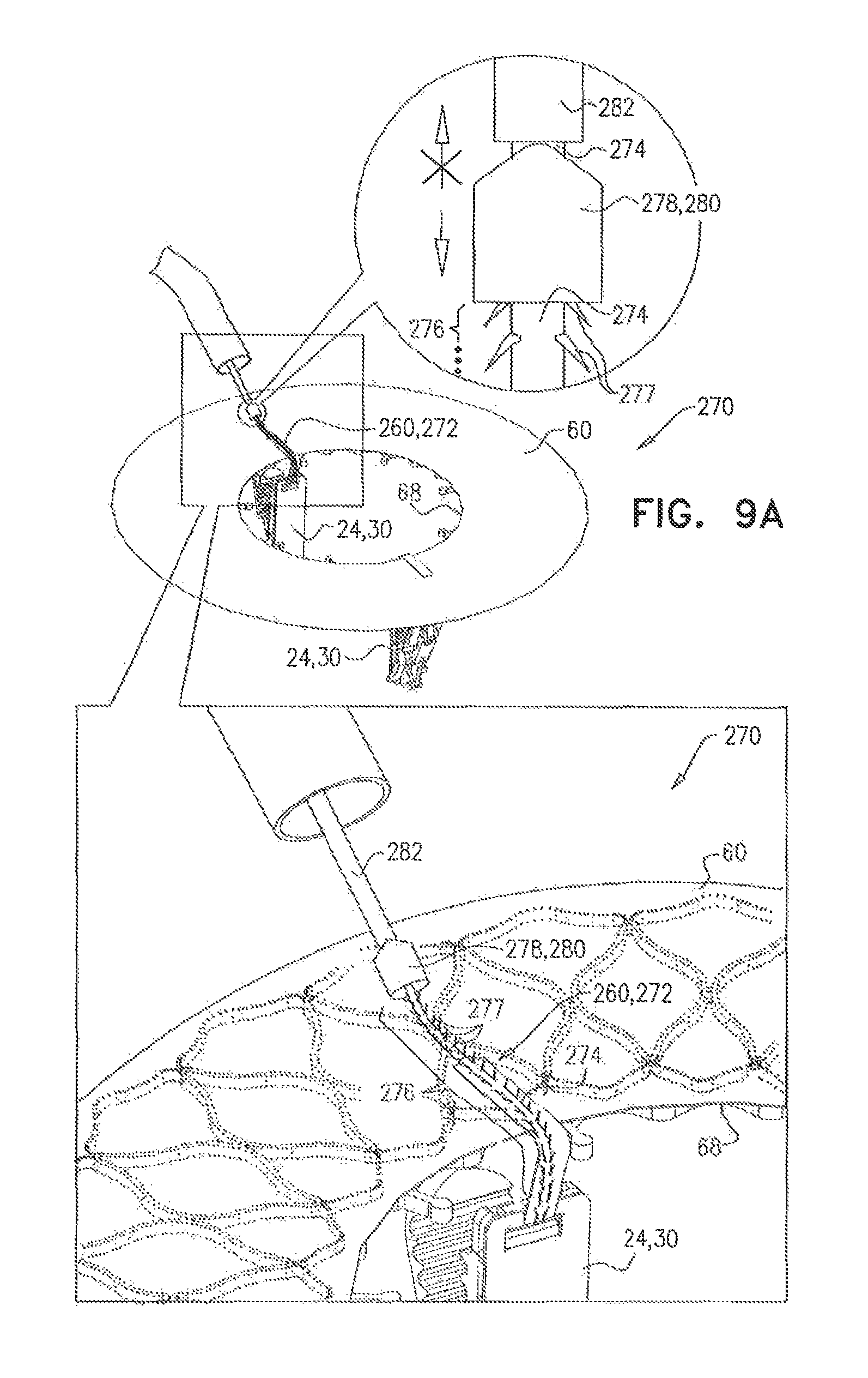
D00013

XML
uspto.report is an independent third-party trademark research tool that is not affiliated, endorsed, or sponsored by the United States Patent and Trademark Office (USPTO) or any other governmental organization. The information provided by uspto.report is based on publicly available data at the time of writing and is intended for informational purposes only.
While we strive to provide accurate and up-to-date information, we do not guarantee the accuracy, completeness, reliability, or suitability of the information displayed on this site. The use of this site is at your own risk. Any reliance you place on such information is therefore strictly at your own risk.
All official trademark data, including owner information, should be verified by visiting the official USPTO website at www.uspto.gov. This site is not intended to replace professional legal advice and should not be used as a substitute for consulting with a legal professional who is knowledgeable about trademark law.