Implant-cinching devices and systems
Sheps , et al. November 17, 2
U.S. patent number 10,835,221 [Application Number 16/154,233] was granted by the patent office on 2020-11-17 for implant-cinching devices and systems. This patent grant is currently assigned to Valtech Cardio, Ltd.. The grantee listed for this patent is Valtech Cardio, Ltd.. Invention is credited to Brian S. Conklin, Yaron Keidar, Tal Sheps, Yuval Zipory.


| United States Patent | 10,835,221 |
| Sheps , et al. | November 17, 2020 |
Implant-cinching devices and systems
Abstract
An implant having an implant body, a gripper, an elastic pouch, and an elongate member. The pouch can be coupled to the gripper, can have a first part and a second part, can have a contracted state toward which the pouch is elastically biased, and can be reversibly stretchable into a stretched state. The elongate member can have a first end portion coupled to the implant body, a second end portion fastened to the second part of the pouch, and a mid-portion extending (i) from the second end portion, through the pouch to the first part of the pouch, and (ii) out of the pouch to the first end portion. In at least one state of the gripper, the mid-portion can be slidable through the gripper and into the pouch. Other embodiments are also described.
| Inventors: | Sheps; Tal (Givat Shmuel, IL), Keidar; Yaron (Haifa, IL), Zipory; Yuval (Modi'in, IL), Conklin; Brian S. (Orange, CA) | ||||||||||
|---|---|---|---|---|---|---|---|---|---|---|---|
| Applicant: |
|
||||||||||
| Assignee: | Valtech Cardio, Ltd. (Or
Yehuda, IL) |
||||||||||
| Family ID: | 66245840 | ||||||||||
| Appl. No.: | 16/154,233 | ||||||||||
| Filed: | October 8, 2018 |
Prior Publication Data
| Document Identifier | Publication Date | |
|---|---|---|
| US 20190125325 A1 | May 2, 2019 | |
Related U.S. Patent Documents
| Application Number | Filing Date | Patent Number | Issue Date | ||
|---|---|---|---|---|---|
| 62580646 | Nov 2, 2017 | ||||
| Current U.S. Class: | 1/1 |
| Current CPC Class: | A61B 17/12013 (20130101); A61B 17/0057 (20130101); A61F 2/2445 (20130101); A61B 17/00234 (20130101); A61B 2017/0496 (20130101); A61B 2017/0649 (20130101); A61F 2/2478 (20130101); A61F 2250/001 (20130101); A61B 17/068 (20130101); A61F 2210/0057 (20130101); A61F 2/9517 (20200501); A61F 2220/0016 (20130101); A61B 2017/00243 (20130101); A61F 2250/0007 (20130101) |
| Current International Class: | A61B 17/00 (20060101); A61B 17/12 (20060101); A61F 2/24 (20060101); A61F 2/95 (20130101); A61B 17/064 (20060101); A61B 17/04 (20060101); A61B 17/068 (20060101) |
References Cited [Referenced By]
U.S. Patent Documents
| 3604488 | September 1971 | Wishart et al. |
| 3656185 | April 1972 | Carpentier |
| 3840018 | October 1974 | Heifetz |
| 3881366 | May 1975 | Bradley et al. |
| 3898701 | August 1975 | La Russa |
| 4042979 | August 1977 | Angell |
| 4118805 | October 1978 | Reimels |
| 4214349 | July 1980 | Munch |
| 4261342 | April 1981 | Aranguren Duo |
| 4290151 | September 1981 | Massana |
| 4434828 | March 1984 | Trincia |
| 4473928 | October 1984 | Johnson |
| 4602911 | July 1986 | Ahmadi et al. |
| 4625727 | December 1986 | Leiboff |
| 4712549 | December 1987 | Peters et al. |
| 4778468 | October 1988 | Hunt et al. |
| 4917698 | April 1990 | Carpentier et al. |
| 4961738 | October 1990 | Mackin |
| 5042707 | August 1991 | Taheri |
| 5061277 | October 1991 | Carpentier et al. |
| 5064431 | November 1991 | Gilbertson et al. |
| 5104407 | April 1992 | Lam et al. |
| 5108420 | April 1992 | Marks |
| 5201880 | April 1993 | Wright et al. |
| 5258008 | November 1993 | Wilk |
| 5300034 | April 1994 | Behnke et al. |
| 5325845 | July 1994 | Adair |
| 5346498 | September 1994 | Greelis et al. |
| 5383852 | January 1995 | Stevens-Wright |
| 5449368 | September 1995 | Kuzmak |
| 5450860 | September 1995 | O'Connor |
| 5464404 | November 1995 | Abela et al. |
| 5474518 | December 1995 | Farrer Velazquez |
| 5477856 | December 1995 | Lundquist |
| 5593424 | January 1997 | Northrup, III |
| 5601572 | February 1997 | Middleman et al. |
| 5626609 | May 1997 | Zvenyatsky et al. |
| 5643317 | July 1997 | Pavcnik et al. |
| 5669919 | September 1997 | Sanders et al. |
| 5676653 | October 1997 | Taylor et al. |
| 5683402 | November 1997 | Cosgrove et al. |
| 5702397 | December 1997 | Goble et al. |
| 5702398 | December 1997 | Tarabishy |
| 5709695 | January 1998 | Northrup, III |
| 5716370 | February 1998 | Williamson, IV et al. |
| 5716397 | February 1998 | Myers |
| 5728116 | March 1998 | Rosenman |
| 5730150 | March 1998 | Peppel et al. |
| 5749371 | May 1998 | Zadini et al. |
| 5782844 | July 1998 | Yoon et al. |
| 5810882 | September 1998 | Bolduc et al. |
| 5824066 | October 1998 | Gross |
| 5830221 | November 1998 | Stein et al. |
| 5843120 | December 1998 | Israel et al. |
| 5855614 | January 1999 | Stevens et al. |
| 5876373 | March 1999 | Giba et al. |
| 5935098 | August 1999 | Blaisdell et al. |
| 5957953 | September 1999 | DiPoto et al. |
| 5961440 | October 1999 | Schweich, Jr. et al. |
| 5961539 | October 1999 | Northrup, III et al. |
| 5984959 | November 1999 | Robertson et al. |
| 6042554 | March 2000 | Rosenman et al. |
| 6045497 | April 2000 | Schweich, Jr. et al. |
| 6050936 | April 2000 | Schweich, Jr. et al. |
| 6059715 | May 2000 | Schweich, Jr. et al. |
| 6074341 | June 2000 | Anderson et al. |
| 6074401 | June 2000 | Gardiner et al. |
| 6074417 | June 2000 | Peredo |
| 6086582 | July 2000 | Altman et al. |
| 6102945 | August 2000 | Campbell |
| 6106550 | August 2000 | Magovern et al. |
| 6110200 | August 2000 | Hinnenkamp |
| 6132390 | October 2000 | Cookston et al. |
| 6143024 | November 2000 | Campbell et al. |
| 6159240 | December 2000 | Sparer et al. |
| 6165119 | December 2000 | Schweich, Jr. et al. |
| 6174332 | January 2001 | Loch et al. |
| 6183411 | February 2001 | Mortier et al. |
| 6187040 | February 2001 | Wright |
| 6210347 | April 2001 | Forsell |
| 6217610 | April 2001 | Carpentier et al. |
| 6231602 | May 2001 | Carpentier et al. |
| 6251092 | June 2001 | Qin et al. |
| 6296656 | October 2001 | Bolduc et al. |
| 6315784 | November 2001 | Djurovic |
| 6319281 | November 2001 | Patel |
| 6328746 | December 2001 | Gambale |
| 6332893 | December 2001 | Mortier et al. |
| 6355030 | March 2002 | Aldrich et al. |
| 6361559 | March 2002 | Houser et al. |
| 6368348 | April 2002 | Gabbay |
| 6402780 | June 2002 | Williamson, IV et al. |
| 6406420 | June 2002 | McCarthy et al. |
| 6406493 | June 2002 | Tu et al. |
| 6419696 | July 2002 | Ortiz et al. |
| 6451054 | September 2002 | Stevens |
| 6458076 | October 2002 | Pruitt |
| 6461366 | October 2002 | Seguin |
| 6470892 | October 2002 | Forsell |
| 6503274 | January 2003 | Howanec, Jr. et al. |
| 6524338 | February 2003 | Gundry |
| 6530952 | March 2003 | Vesely |
| 6533772 | March 2003 | Sherts et al. |
| 6537314 | March 2003 | Langberg et al. |
| 6547801 | April 2003 | Dargent et al. |
| 6554845 | April 2003 | Fleenor et al. |
| 6564805 | May 2003 | Garrison et al. |
| 6565603 | May 2003 | Cox |
| 6569198 | May 2003 | Wilson et al. |
| 6579297 | June 2003 | Bicek et al. |
| 6589160 | July 2003 | Schweich, Jr. et al. |
| 6592593 | July 2003 | Parodi et al. |
| 6602288 | August 2003 | Cosgrove et al. |
| 6602289 | August 2003 | Colvin et al. |
| 6613078 | September 2003 | Barone |
| 6613079 | September 2003 | Wolinsky et al. |
| 6619291 | September 2003 | Hlavka et al. |
| 6626899 | September 2003 | Houser et al. |
| 6626917 | September 2003 | Craig |
| 6626930 | September 2003 | Allen et al. |
| 6629534 | October 2003 | St. Goar et al. |
| 6629921 | October 2003 | Schweich, Jr. et al. |
| 6651671 | November 2003 | Donlon et al. |
| 6652556 | November 2003 | VanTassel et al. |
| 6682558 | January 2004 | Tu et al. |
| 6689125 | February 2004 | Keith et al. |
| 6689164 | February 2004 | Seguin |
| 6695866 | February 2004 | Kuehn et al. |
| 6702826 | March 2004 | Liddicoat et al. |
| 6702846 | March 2004 | Mikus et al. |
| 6706065 | March 2004 | Langberg et al. |
| 6709385 | March 2004 | Forsell |
| 6709456 | March 2004 | Langherg et al. |
| 6711444 | March 2004 | Koblish |
| 6719786 | April 2004 | Ryan et al. |
| 6723038 | April 2004 | Schroeder et al. |
| 6726716 | April 2004 | Marquez |
| 6726717 | April 2004 | Alfieri et al. |
| 6730121 | May 2004 | Ortiz et al. |
| 6749630 | June 2004 | McCarthy et al. |
| 6752813 | June 2004 | Goldfarb et al. |
| 6764310 | July 2004 | Ichihashi et al. |
| 6764510 | July 2004 | Vidlund et al. |
| 6764810 | July 2004 | Ma et al. |
| 6770083 | August 2004 | Seguin |
| 6786924 | September 2004 | Ryan et al. |
| 6786925 | September 2004 | Schoon et al. |
| 6790231 | September 2004 | Liddicoat et al. |
| 6797001 | September 2004 | Mathis et al. |
| 6797002 | September 2004 | Spence et al. |
| 6802319 | October 2004 | Stevens et al. |
| 6805710 | October 2004 | Bolling et al. |
| 6805711 | October 2004 | Quijano et al. |
| 6855126 | February 2005 | Flinchbaugh |
| 6858039 | February 2005 | McCarthy |
| 6884250 | April 2005 | Monassevitch et al. |
| 6893459 | May 2005 | Macoviak |
| 6908478 | June 2005 | Alferness et al. |
| 6908482 | June 2005 | McCarthy et al. |
| 6918917 | July 2005 | Nguyen et al. |
| 6926730 | August 2005 | Nguyen et al. |
| 6960217 | November 2005 | Bolduc |
| 6964684 | November 2005 | Ortiz et al. |
| 6964686 | November 2005 | Gordon |
| 6976995 | December 2005 | Mathis et al. |
| 6986775 | January 2006 | Morales et al. |
| 6989028 | January 2006 | Lashinski et al. |
| 6997951 | February 2006 | Solem et al. |
| 7004176 | February 2006 | Lau |
| 7007798 | March 2006 | Happonen et al. |
| 7011669 | March 2006 | Kimblad |
| 7011682 | March 2006 | Lashinski et al. |
| 7018406 | March 2006 | Seguin et al. |
| 7037334 | May 2006 | Hlavka et al. |
| 7087064 | June 2006 | Hyde |
| 7077850 | July 2006 | Kortenbach |
| 7077862 | July 2006 | Vidlund et al. |
| 7101395 | September 2006 | Tremulis et al. |
| 7101396 | September 2006 | Artof et al. |
| 7112207 | September 2006 | Allen et al. |
| 7118595 | October 2006 | Ryan et al. |
| 7125421 | October 2006 | Tremulis et al. |
| 7150737 | December 2006 | Purdy et al. |
| 7159593 | January 2007 | McCarthy et al. |
| 7166127 | January 2007 | Spence et al. |
| 7169187 | January 2007 | Datta et al. |
| 7172625 | February 2007 | Shu et al. |
| 7175660 | February 2007 | Cartledge et al. |
| 7186262 | March 2007 | Saadat |
| 7186264 | March 2007 | Liddicoat et al. |
| 7189199 | March 2007 | McCarthy et al. |
| 7192443 | March 2007 | Solem et al. |
| 7220277 | May 2007 | Arru et al. |
| 7226467 | June 2007 | Lucatero et al. |
| 7226477 | June 2007 | Cox |
| 7226647 | June 2007 | Kasperchik et al. |
| 7229452 | June 2007 | Kayan |
| 7238191 | July 2007 | Bachmann |
| 7288097 | October 2007 | Seguin |
| 7294148 | November 2007 | McCarthy |
| 7311728 | December 2007 | Solem et al. |
| 7311729 | December 2007 | Mathis et al. |
| 7314485 | January 2008 | Mathis |
| 7316710 | January 2008 | Cheng et al. |
| 7329279 | February 2008 | Haug et al. |
| 7329280 | February 2008 | Bolling et al. |
| 7335213 | February 2008 | Hyde et al. |
| 7361190 | April 2008 | Shaoulian et al. |
| 7364588 | April 2008 | Mathis et al. |
| 7377941 | May 2008 | Rhee et al. |
| 7390329 | June 2008 | Westra et al. |
| 7404824 | July 2008 | Weber et al. |
| 7431692 | October 2008 | Zollinger et al. |
| 7442207 | October 2008 | Rafiee |
| 7452376 | November 2008 | Lim et al. |
| 7455690 | November 2008 | Cartledge et al. |
| 7485142 | February 2009 | Milo |
| 7485143 | February 2009 | Webler et al. |
| 7500989 | March 2009 | Solem et al. |
| 7507252 | March 2009 | Lashinski et al. |
| 7510575 | March 2009 | Spenser et al. |
| 7510577 | March 2009 | Moaddeb et al. |
| 7527647 | May 2009 | Spence |
| 7530995 | May 2009 | Quijano et al. |
| 7549983 | June 2009 | Roue et al. |
| 7559936 | July 2009 | Levine |
| 7562660 | July 2009 | Saadat |
| 7563267 | July 2009 | Goldfarb et al. |
| 7563273 | July 2009 | Goldfarb et al. |
| 7569062 | August 2009 | Kuehn et al. |
| 7585321 | September 2009 | Cribier |
| 7588582 | September 2009 | Starksen et al. |
| 7591826 | September 2009 | Alferness et al. |
| 7604646 | October 2009 | Goldfarb et al. |
| 7608091 | October 2009 | Goldfarb et al. |
| 7608103 | October 2009 | McCarthy |
| 7625403 | December 2009 | Krivoruchko |
| 7632303 | December 2009 | Stalker et al. |
| 7635329 | December 2009 | Goldfarb et al. |
| 7635386 | December 2009 | Gammie |
| 7655015 | February 2010 | Goldfarb et al. |
| 7666204 | February 2010 | Thornton et al. |
| 7682319 | March 2010 | Martin et al. |
| 7682369 | March 2010 | Seguin |
| 7683538 | March 2010 | Yoo et al. |
| 7686822 | March 2010 | Shayani |
| 7699892 | April 2010 | Rafiee et al. |
| 7704269 | April 2010 | St. Goar et al. |
| 7704277 | April 2010 | Zakay et al. |
| 7722666 | May 2010 | Lafontaine |
| 7736388 | June 2010 | Goldfarb et al. |
| 7780726 | June 2010 | Seguin |
| 7748389 | July 2010 | Salahieh et al. |
| 7753924 | July 2010 | Starksen et al. |
| 7758632 | July 2010 | Hojeibane et al. |
| 7871368 | January 2011 | Zollinger et al. |
| 7871433 | January 2011 | Lattouf |
| 7883475 | February 2011 | Dupont et al. |
| 7892281 | February 2011 | Seguin et al. |
| 7927370 | April 2011 | Webler et al. |
| 7927371 | April 2011 | Navia et al. |
| 7942927 | May 2011 | Kaye et al. |
| 7947056 | May 2011 | Griego et al. |
| 7955315 | June 2011 | Feinberg et al. |
| 7955377 | June 2011 | Melsheimer |
| 7992567 | August 2011 | Hirotstika et al. |
| 7993368 | August 2011 | Gambale et al. |
| 7993397 | August 2011 | Lashinski et al. |
| 8012201 | September 2011 | Lashinski et al. |
| 8034103 | October 2011 | Burriesci et al. |
| 8052592 | November 2011 | Goldfarb et al. |
| 8057493 | November 2011 | Goldfarb et al. |
| 8062355 | November 2011 | Figulla et al. |
| 8070804 | December 2011 | Hyde et al. |
| 8070805 | December 2011 | Vidlund et al. |
| 8075616 | December 2011 | Solem et al. |
| 8100964 | January 2012 | Spence |
| 8123801 | February 2012 | Milo |
| 8142493 | March 2012 | Spence et al. |
| 8142495 | March 2012 | Hasenkam et al. |
| 8142496 | March 2012 | Berreklouw |
| 8147542 | April 2012 | Maisano et al. |
| 8152844 | April 2012 | Rao et al. |
| 8163013 | April 2012 | Machold et al. |
| 8187299 | May 2012 | Goldfarb et al. |
| 8187324 | May 2012 | Webler et al. |
| 8202315 | June 2012 | Hlavka et al. |
| 8206439 | June 2012 | Gomez Duran |
| 8216302 | July 2012 | Wilson et al. |
| 8231671 | July 2012 | Kim |
| 8262725 | September 2012 | Subramanian |
| 8265758 | September 2012 | Policker et al. |
| 8277502 | October 2012 | Miller et al. |
| 8287584 | October 2012 | Salahieh et al. |
| 8287591 | October 2012 | Keidar et al. |
| 8292884 | October 2012 | Levine et al. |
| 8303608 | November 2012 | Goldfarb et al. |
| 8323334 | December 2012 | Deem et al. |
| 8328868 | December 2012 | Paul et al. |
| 8333777 | December 2012 | Schaller et al. |
| 8343173 | January 2013 | Starksen et al. |
| 8343174 | January 2013 | Goldfarb et al. |
| 8343213 | January 2013 | Salahieh et al. |
| 8349002 | January 2013 | Milo |
| 8353956 | January 2013 | Miller et al. |
| 8357195 | January 2013 | Kuehn |
| 8382829 | February 2013 | Call et al. |
| 8388680 | March 2013 | Starksen et al. |
| 8393517 | March 2013 | Milo |
| 8419825 | April 2013 | Burgler et al. |
| 8430926 | April 2013 | Kirson |
| 8449573 | May 2013 | Chu |
| 8449599 | May 2013 | Chau et al. |
| 8454686 | June 2013 | Alkhatib |
| 8460370 | June 2013 | Zakay |
| 8460371 | June 2013 | Hlavka et al. |
| 8475491 | July 2013 | Milo |
| 8475525 | July 2013 | Maisano et al. |
| 8480732 | July 2013 | Subramanian |
| 8518107 | August 2013 | Tsukashima et al. |
| 8523940 | September 2013 | Richardson et al. |
| 8551161 | October 2013 | Dolan |
| 8585755 | November 2013 | Chau et al. |
| 8591576 | November 2013 | Hasenkam et al. |
| 8608797 | December 2013 | Gross et al. |
| 8628569 | January 2014 | Benichou et al. |
| 8628571 | January 2014 | Hacohen et al. |
| 8641727 | February 2014 | Starksen et al. |
| 8652202 | February 2014 | Alon et al. |
| 8652203 | February 2014 | Quadri et al. |
| 8679174 | March 2014 | Ottma et al. |
| 8685086 | April 2014 | Navia et al. |
| 8728097 | May 2014 | Sugimoto et al. |
| 8728155 | May 2014 | Montorfano et al. |
| 8734467 | May 2014 | Miller et al. |
| 8734699 | May 2014 | Heideman et al. |
| 8740920 | June 2014 | Goldfarb et al. |
| 8747463 | June 2014 | Fogarty et al. |
| 8778021 | July 2014 | Cartledge |
| 8784481 | July 2014 | Alkhatib et al. |
| 8790367 | July 2014 | Nguyen et al. |
| 8790394 | July 2014 | Miller et al. |
| 8795298 | August 2014 | Hernlund et al. |
| 8795355 | August 2014 | Alkhatib |
| 8795356 | August 2014 | Quadri et al. |
| 8795357 | August 2014 | Yohanan et al. |
| 8808366 | August 2014 | Braido et al. |
| 8808368 | August 2014 | Maisano et al. |
| 8845717 | September 2014 | Khairkhahan et al. |
| 8845723 | September 2014 | Spence et al. |
| 8852261 | October 2014 | White |
| 8852272 | October 2014 | Gross et al. |
| 8858623 | October 2014 | Miller et al. |
| 8864822 | October 2014 | Spence et al. |
| 8870948 | October 2014 | Erzberger et al. |
| 8870949 | October 2014 | Rowe |
| 8888843 | November 2014 | Khairkhahan et al. |
| 8889861 | November 2014 | Skead et al. |
| 8894702 | November 2014 | Quadri et al. |
| 8911461 | December 2014 | Traynor et al. |
| 8911494 | December 2014 | Hammer et al. |
| 8926696 | January 2015 | Cabiri et al. |
| 8926697 | January 2015 | Gross et al. |
| 8932343 | January 2015 | Alkhatib et al. |
| 8932348 | January 2015 | Solem et al. |
| 8940044 | January 2015 | Hammer et al. |
| 8945211 | February 2015 | Sugimoto |
| 8951285 | February 2015 | Sugimoto et al. |
| 8951286 | February 2015 | Sugimoto et al. |
| 8961595 | February 2015 | Alkhatib |
| 8961602 | February 2015 | Kovach et al. |
| 8979922 | March 2015 | Jayasinghe et al. |
| 8992604 | March 2015 | Gross et al. |
| 9005273 | April 2015 | Salahieh et al. |
| 9011520 | April 2015 | Miller et al. |
| 9011530 | April 2015 | Reich et al. |
| 9023100 | May 2015 | Quadri et al. |
| 9072603 | July 2015 | Tuval et al. |
| 9107749 | August 2015 | Bobo et al. |
| 9119719 | September 2015 | Zipory et al. |
| 9125632 | September 2015 | Loulmet et al. |
| 9125742 | September 2015 | Yoganathan et al. |
| 9138316 | September 2015 | Bielefeld |
| 9173646 | November 2015 | Fabro |
| 9180005 | November 2015 | Lashinski et al. |
| 9180007 | November 2015 | Reich et al. |
| 9192472 | November 2015 | Gross et al. |
| 9198756 | December 2015 | Aklog et al. |
| 9226825 | January 2016 | Starksen et al. |
| 9265608 | February 2016 | Miller et al. |
| 9326857 | May 2016 | Cartledge et al. |
| 9414921 | August 2016 | Miller et al. |
| 9427316 | August 2016 | Schweich, Jr. et al. |
| 9474606 | October 2016 | Zipory et al. |
| 9526613 | December 2016 | Gross et al. |
| 9561104 | February 2017 | Miller et al. |
| 9693865 | July 2017 | Gilmore et al. |
| 9730793 | August 2017 | Reich et al. |
| 9788941 | October 2017 | Hacohen |
| 9801720 | October 2017 | Gilmore et al. |
| 9907547 | March 2018 | Gilmore et al. |
| 2001/0021874 | September 2001 | Carpentier et al. |
| 2002/0022862 | February 2002 | Grafton et al. |
| 2002/0082525 | June 2002 | Oslund et al. |
| 2002/0087048 | July 2002 | Brock et al. |
| 2002/0103532 | August 2002 | Langberg et al. |
| 2002/0151916 | October 2002 | Muramatsu et al. |
| 2002/0151970 | October 2002 | Garrison et al. |
| 2002/0169358 | November 2002 | Mortier et al. |
| 2002/0177904 | November 2002 | Huxel et al. |
| 2002/0188301 | December 2002 | Dallara et al. |
| 2002/0188350 | December 2002 | Arru et al. |
| 2002/0198586 | December 2002 | Inoue |
| 2003/0050693 | March 2003 | Quijano et al. |
| 2003/0078465 | April 2003 | Pai et al. |
| 2003/0078653 | April 2003 | Vesely et al. |
| 2003/0105519 | June 2003 | Fasol et al. |
| 2003/0114901 | June 2003 | Loeb et al. |
| 2003/0120340 | June 2003 | Liska et al. |
| 2003/0144657 | July 2003 | Bowe et al. |
| 2003/0171760 | September 2003 | Gambale |
| 2003/0199974 | October 2003 | Lee et al. |
| 2003/0204195 | October 2003 | Keane et al. |
| 2003/0229350 | December 2003 | Kay |
| 2003/0229395 | December 2003 | Cox |
| 2004/0010287 | January 2004 | Bonutti |
| 2004/0019359 | January 2004 | Worley et al. |
| 2004/0019377 | January 2004 | Taylor et al. |
| 2004/0024451 | February 2004 | Johnson et al. |
| 2004/0039442 | February 2004 | St. Goar et al. |
| 2004/0059413 | March 2004 | Argento |
| 2004/0122514 | June 2004 | Fogarty et al. |
| 2004/0127982 | July 2004 | Machold et al. |
| 2004/0133274 | July 2004 | Webler et al. |
| 2004/0133374 | July 2004 | Kattan |
| 2004/0138744 | July 2004 | Lashinski et al. |
| 2004/0138745 | July 2004 | Macoviak et al. |
| 2004/0148019 | July 2004 | Vidlund et al. |
| 2004/0148020 | July 2004 | Vidlund et al. |
| 2004/0148021 | July 2004 | Cartledge et al. |
| 2004/0176788 | September 2004 | Opolski |
| 2004/0181287 | September 2004 | Gellman |
| 2004/0186566 | September 2004 | Hindrichs et al. |
| 2004/0193191 | September 2004 | Starksen et al. |
| 2004/0243227 | December 2004 | Starksen et al. |
| 2004/0260317 | December 2004 | Bloom et al. |
| 2004/0260393 | December 2004 | Randert et al. |
| 2004/0260394 | December 2004 | Douk et al. |
| 2004/0267358 | December 2004 | Reitan |
| 2005/0004668 | January 2005 | Aklog et al. |
| 2005/0010287 | January 2005 | Macoviak et al. |
| 2005/0010787 | January 2005 | Tarbouriech |
| 2005/0016560 | January 2005 | Voughlohn |
| 2005/0049692 | March 2005 | Numamoto et al. |
| 2005/0055038 | March 2005 | Kelleher et al. |
| 2005/0055087 | March 2005 | Starksen |
| 2005/0060030 | March 2005 | Lashinski et al. |
| 2005/0065601 | March 2005 | Lee et al. |
| 2005/0070999 | March 2005 | Spence |
| 2005/0075727 | April 2005 | Wheatley |
| 2005/0090827 | April 2005 | Gedebou |
| 2005/0090834 | April 2005 | Chiang et al. |
| 2005/0096740 | May 2005 | Langberg et al. |
| 2005/0107871 | May 2005 | Realyvasquez et al. |
| 2005/0119734 | June 2005 | Spence et al. |
| 2005/0125002 | June 2005 | Baran et al. |
| 2005/0125011 | June 2005 | Spence et al. |
| 2005/0131533 | June 2005 | Alfieri et al. |
| 2005/0137686 | June 2005 | Salahieh et al. |
| 2005/0137688 | June 2005 | Salahieh et al. |
| 2005/0137695 | June 2005 | Salahieh et al. |
| 2005/0177228 | June 2005 | Solem et al. |
| 2005/0159728 | July 2005 | Armour et al. |
| 2005/0171601 | August 2005 | Cosgrove et al. |
| 2005/0177180 | August 2005 | Kaganov et al. |
| 2005/0187568 | August 2005 | Klenk et al. |
| 2005/0192596 | September 2005 | Jugenheimer et al. |
| 2005/0203549 | September 2005 | Realyvasquez |
| 2005/0203606 | September 2005 | VanCamp |
| 2005/0216039 | September 2005 | Lederman |
| 2005/0216079 | September 2005 | MaCoviak |
| 2005/0222665 | October 2005 | Aranyi |
| 2005/0256532 | November 2005 | Nayak et al. |
| 2005/0267478 | December 2005 | Corradi et al. |
| 2005/0273138 | December 2005 | To et al. |
| 2005/0288778 | December 2005 | Shaoulian et al. |
| 2006/0004442 | January 2006 | Spenser et al. |
| 2006/0004443 | January 2006 | Liddicoat et al. |
| 2006/0020326 | January 2006 | Bolduc et al. |
| 2006/0020327 | January 2006 | Lashinski et al. |
| 2006/0020333 | January 2006 | Lashinski et al. |
| 2006/0020336 | January 2006 | Liddicoat |
| 2006/0025787 | February 2006 | Morales et al. |
| 2006/0025858 | February 2006 | Alameddine |
| 2006/0030885 | February 2006 | Hyde |
| 2006/0041319 | February 2006 | Taylor et al. |
| 2006/0069429 | March 2006 | Spence et al. |
| 2006/0074486 | April 2006 | Liddicoat et al. |
| 2006/0085012 | April 2006 | Dolan |
| 2006/0095009 | May 2006 | Lampropoulos et al. |
| 2006/0106423 | May 2006 | Weisel et al. |
| 2006/0116757 | June 2006 | Lashinski et al. |
| 2006/0122633 | June 2006 | To et al. |
| 2006/0129166 | June 2006 | Lavelle |
| 2006/0184240 | June 2006 | Jimenez et al. |
| 2006/0149280 | July 2006 | Harvie et al. |
| 2006/0149368 | July 2006 | Spence |
| 2006/0161265 | July 2006 | Levine et al. |
| 2006/0184242 | August 2006 | Lichtenstein |
| 2006/0195134 | August 2006 | Crittenden |
| 2006/0206203 | September 2006 | Yang et al. |
| 2006/0241622 | October 2006 | Zergiebel |
| 2006/0241656 | October 2006 | Starksen et al. |
| 2006/0241748 | October 2006 | Lee et al. |
| 2006/0247763 | November 2006 | Slater |
| 2006/0259135 | November 2006 | Navia et al. |
| 2006/0271175 | November 2006 | Woolfson et al. |
| 2006/0282161 | December 2006 | Huynh et al. |
| 2006/0287661 | December 2006 | Bolduc et al. |
| 2006/0287716 | December 2006 | Banbury et al. |
| 2007/0001627 | January 2007 | Lin et al. |
| 2007/0016287 | January 2007 | Cartledge et al. |
| 2007/0016288 | January 2007 | Gurskis et al. |
| 2007/0021781 | January 2007 | Jervis et al. |
| 2007/0027533 | February 2007 | Douk |
| 2007/0027536 | February 2007 | Mihaljevic |
| 2007/0038221 | February 2007 | Fine et al. |
| 2007/0038293 | February 2007 | St.Goar et al. |
| 2007/0038296 | February 2007 | Navia et al. |
| 2007/0039425 | February 2007 | Wang |
| 2007/0049942 | March 2007 | Hindrichs et al. |
| 2007/0049970 | March 2007 | Belef et al. |
| 2007/0051377 | March 2007 | Douk et al. |
| 2007/0055206 | March 2007 | To et al. |
| 2007/0061010 | March 2007 | Hauser et al. |
| 2007/0066863 | March 2007 | Rafiee et al. |
| 2007/0078297 | April 2007 | Rafiee et al. |
| 2007/0080188 | April 2007 | Spence et al. |
| 2007/0083168 | April 2007 | Whiting et al. |
| 2007/0100427 | May 2007 | Perouse |
| 2007/0106328 | May 2007 | Wardle et al. |
| 2007/0112359 | May 2007 | Kimura et al. |
| 2007/0112422 | May 2007 | Dehdashtian |
| 2007/0118151 | May 2007 | Davidson |
| 2007/0118154 | May 2007 | Crabtree |
| 2007/0118213 | May 2007 | Loulmet |
| 2007/0118215 | May 2007 | Moaddeb |
| 2007/0142907 | June 2007 | Moaddeb et al. |
| 2007/0162111 | July 2007 | Fukamachi et al. |
| 2007/0198082 | August 2007 | Kapadia et al. |
| 2007/0219558 | September 2007 | Deutsch |
| 2007/0239208 | October 2007 | Crawford |
| 2007/0255397 | November 2007 | Ryan et al. |
| 2007/0255400 | November 2007 | Parravicini et al. |
| 2007/0270755 | November 2007 | Von Oepen et al. |
| 2007/0276437 | November 2007 | Call et al. |
| 2007/0282375 | December 2007 | Hindrichs et al. |
| 2007/0282429 | December 2007 | Hauser et al. |
| 2007/0295172 | December 2007 | Swartz |
| 2008/0004697 | January 2008 | Lichtenstein et al. |
| 2008/0027483 | January 2008 | Cartledge et al. |
| 2008/0027555 | January 2008 | Hawkins |
| 2008/0035160 | February 2008 | Woodson et al. |
| 2008/0039935 | February 2008 | Buch et al. |
| 2008/0051703 | February 2008 | Thornton et al. |
| 2008/0058595 | March 2008 | Snoke et al. |
| 2008/0065011 | March 2008 | Marchand et al. |
| 2008/0065204 | March 2008 | Macoviak et al. |
| 2008/0071366 | March 2008 | Tuval et al. |
| 2008/0086138 | April 2008 | Stone et al. |
| 2008/0086203 | April 2008 | Roberts |
| 2008/0091257 | April 2008 | Andreas et al. |
| 2008/0097523 | April 2008 | Bolduc et al. |
| 2008/0103572 | May 2008 | Gerber |
| 2008/0140116 | June 2008 | Bonutti |
| 2008/0167713 | July 2008 | Bolling |
| 2008/0167714 | July 2008 | St. Goar et al. |
| 2008/0195126 | August 2008 | Solem |
| 2008/0195200 | August 2008 | Vidlund et al. |
| 2008/0208265 | August 2008 | Frazier et al. |
| 2008/0221672 | September 2008 | Lamphere et al. |
| 2008/0262480 | October 2008 | Stahler et al. |
| 2008/0262609 | October 2008 | Gross et al. |
| 2008/0275300 | November 2008 | Rothe et al. |
| 2008/0275469 | November 2008 | Fanton et al. |
| 2008/0275551 | November 2008 | Alfieri |
| 2008/0281353 | November 2008 | Aranyi et al. |
| 2008/0281411 | November 2008 | Berreklouw |
| 2008/0288044 | November 2008 | Osborne |
| 2008/0288062 | November 2008 | Andrieu et al. |
| 2008/0300537 | December 2008 | Bowman |
| 2008/0300629 | December 2008 | Surti |
| 2009/0028670 | January 2009 | Garcia et al. |
| 2009/0043381 | February 2009 | Macoviak et al. |
| 2009/0054969 | February 2009 | Salahieh et al. |
| 2009/0062866 | March 2009 | Jackson |
| 2009/0076586 | March 2009 | Hauser et al. |
| 2009/0076600 | March 2009 | Quinn |
| 2009/0088837 | April 2009 | Gillinov et al. |
| 2009/0093677 | April 2009 | Keidar et al. |
| 2009/0099650 | April 2009 | Bolduc et al. |
| 2009/0105816 | April 2009 | Olsen et al. |
| 2009/0125102 | May 2009 | Cartledge et al. |
| 2009/0171439 | July 2009 | Nissl |
| 2009/0177266 | July 2009 | Powell et al. |
| 2009/0177274 | July 2009 | Scorsin et al. |
| 2009/0248148 | October 2009 | Shaolian et al. |
| 2009/0254103 | October 2009 | Deutsch |
| 2009/0264994 | October 2009 | Saadat |
| 2009/0287231 | November 2009 | Brooks et al. |
| 2009/0287304 | November 2009 | Dahlgren et al. |
| 2009/0299409 | December 2009 | Coe et al. |
| 2009/0326648 | December 2009 | Machold et al. |
| 2010/0001038 | January 2010 | Levin et al. |
| 2010/0010538 | January 2010 | Juravic et al. |
| 2010/0023118 | January 2010 | Medlock et al. |
| 2010/0030014 | February 2010 | Ferrazzi |
| 2010/0030328 | February 2010 | Seguin et al. |
| 2010/0042147 | February 2010 | Janovsky et al. |
| 2010/0063542 | March 2010 | van der Burg et al. |
| 2010/0063550 | March 2010 | Felix et al. |
| 2010/0076499 | March 2010 | McNamara et al. |
| 2010/0094248 | April 2010 | Nguyen et al. |
| 2010/0114180 | May 2010 | Rock et al. |
| 2010/0121349 | May 2010 | Meier et al. |
| 2010/0121435 | May 2010 | Subramanian et al. |
| 2010/0121437 | May 2010 | Subramanian et al. |
| 2010/0130992 | May 2010 | Machold et al. |
| 2010/0152845 | June 2010 | Bloom et al. |
| 2010/0161043 | June 2010 | Maisano et al. |
| 2010/0168845 | July 2010 | Wright |
| 2010/0174358 | July 2010 | Rabkin et al. |
| 2010/0179574 | July 2010 | Longoria et al. |
| 2010/0217184 | August 2010 | Koblish et al. |
| 2010/0217382 | August 2010 | Chau et al. |
| 2010/0234935 | September 2010 | Bashiri et al. |
| 2010/0249908 | September 2010 | Chau et al. |
| 2010/0249915 | September 2010 | Zhang |
| 2010/0249920 | September 2010 | Bolling et al. |
| 2010/0262232 | October 2010 | Annest |
| 2010/0262233 | October 2010 | He |
| 2010/0286628 | November 2010 | Gross |
| 2010/0305475 | December 2010 | Hinchliffe et al. |
| 2010/0324598 | December 2010 | Anderson |
| 2011/0004210 | January 2011 | Johnson et al. |
| 2011/0004298 | January 2011 | Lee et al. |
| 2011/0009956 | January 2011 | Cartledge et al. |
| 2011/0011917 | January 2011 | Loulmet |
| 2011/0026208 | February 2011 | Utsuro et al. |
| 2011/0029066 | February 2011 | Gilad et al. |
| 2011/0035000 | February 2011 | Nieminen et al. |
| 2011/0066231 | March 2011 | Cartledge et al. |
| 2011/0067770 | March 2011 | Pederson et al. |
| 2011/0071626 | March 2011 | Wright et al. |
| 2011/0082538 | April 2011 | Dahlgren et al. |
| 2011/0087146 | April 2011 | Ryan et al. |
| 2011/0093002 | April 2011 | Rucker et al. |
| 2011/0118832 | May 2011 | Punjabi |
| 2011/0137410 | June 2011 | Hacohen |
| 2011/0144703 | June 2011 | Krause et al. |
| 2011/0202130 | August 2011 | Cartledge et al. |
| 2011/0208283 | August 2011 | Rust |
| 2011/0230941 | September 2011 | Markus |
| 2011/0230961 | September 2011 | Langer et al. |
| 2011/0238088 | September 2011 | Bolduc et al. |
| 2011/0257433 | October 2011 | Walker |
| 2011/0257633 | October 2011 | Cartledge et al. |
| 2011/0264208 | October 2011 | Duffy et al. |
| 2011/0276062 | November 2011 | Bolduc |
| 2011/0288435 | November 2011 | Christy et al. |
| 2011/0301498 | December 2011 | Maenhout et al. |
| 2012/0078355 | March 2012 | Zipory et al. |
| 2012/0078359 | March 2012 | Li et al. |
| 2012/0089022 | April 2012 | House et al. |
| 2012/0095552 | April 2012 | Spence et al. |
| 2012/0109155 | May 2012 | Robinson et al. |
| 2012/0150290 | June 2012 | Gabbay |
| 2012/0158021 | June 2012 | Morrill |
| 2012/0179086 | July 2012 | Shank et al. |
| 2012/0191182 | July 2012 | Hauser et al. |
| 2012/0226349 | September 2012 | Tuval et al. |
| 2012/0239142 | September 2012 | Liu et al. |
| 2012/0245604 | September 2012 | Tegzes |
| 2012/0271198 | October 2012 | Whittaker et al. |
| 2012/0296349 | November 2012 | Smith et al. |
| 2012/0296417 | November 2012 | Hill |
| 2012/0310330 | December 2012 | Buchbinder et al. |
| 2012/0323313 | December 2012 | Seguin |
| 2013/0030522 | January 2013 | Rowe et al. |
| 2013/0046373 | February 2013 | Cartledge et al. |
| 2013/0079873 | March 2013 | Migliazza et al. |
| 2013/0085529 | April 2013 | Housman |
| 2013/0090724 | April 2013 | Subramanian et al. |
| 2013/0096673 | April 2013 | Hill et al. |
| 2013/0116776 | May 2013 | Gross et al. |
| 2013/0123910 | May 2013 | Cartledge et al. |
| 2013/0131791 | May 2013 | Hlavka et al. |
| 2013/0166017 | June 2013 | Cartledge et al. |
| 2013/0190863 | July 2013 | Call et al. |
| 2013/0204361 | August 2013 | Adams et al. |
| 2013/0226289 | August 2013 | Shaolian et al. |
| 2013/0226290 | August 2013 | Yellin et al. |
| 2013/0268069 | October 2013 | Zakai et al. |
| 2013/0289718 | October 2013 | Tsukashima et al. |
| 2013/0297013 | November 2013 | Klima et al. |
| 2013/0304093 | November 2013 | Serina et al. |
| 2014/0081394 | March 2014 | Keranen et al. |
| 2014/0088368 | March 2014 | Park |
| 2014/0094826 | April 2014 | Sutherland et al. |
| 2014/0094903 | April 2014 | Miller et al. |
| 2014/0094906 | April 2014 | Spence et al. |
| 2014/0135799 | May 2014 | Henderson |
| 2014/0142619 | May 2014 | Serina et al. |
| 2014/0142695 | May 2014 | Gross et al. |
| 2014/0148849 | May 2014 | Serina et al. |
| 2014/0155783 | June 2014 | Starksen et al. |
| 2014/0163670 | June 2014 | Alon et al. |
| 2014/0163690 | June 2014 | White |
| 2014/0188108 | July 2014 | Goodine et al. |
| 2014/0188140 | July 2014 | Meter et al. |
| 2014/0188215 | July 2014 | Hlavka et al. |
| 2014/0194976 | July 2014 | Starksen et al. |
| 2014/0207231 | July 2014 | Hacohen et al. |
| 2014/0243859 | August 2014 | Robinson |
| 2014/0243894 | August 2014 | Groothuis et al. |
| 2014/0243963 | August 2014 | Sheds et al. |
| 2014/0275757 | September 2014 | Goodwin et al. |
| 2014/0276648 | September 2014 | Hammer et al. |
| 2014/0296962 | October 2014 | Cartledge et al. |
| 2014/0303649 | October 2014 | Nguyen et al. |
| 2014/0303720 | October 2014 | Sugimoto et al. |
| 2014/0309661 | October 2014 | Sheps et al. |
| 2014/0309730 | October 2014 | Alon et al. |
| 2014/0343668 | November 2014 | Zipory et al. |
| 2014/0350660 | November 2014 | Cocks et al. |
| 2014/0379006 | December 2014 | Sutherland et al. |
| 2015/0018940 | January 2015 | Quill et al. |
| 2015/0051697 | February 2015 | Spence et al. |
| 2015/0081006 | March 2015 | Chuter |
| 2015/0081014 | March 2015 | Gross et al. |
| 2015/0112432 | April 2015 | Reich et al. |
| 2015/0127097 | May 2015 | Neumann et al. |
| 2015/0182336 | July 2015 | Zipory et al. |
| 2015/0272586 | October 2015 | Herman et al. |
| 2015/0272734 | October 2015 | Sheps et al. |
| 2015/0282931 | October 2015 | Brunnett et al. |
| 2016/0008130 | January 2016 | Hasin |
| 2016/0008132 | January 2016 | Cabiri et al. |
| 2016/0058557 | March 2016 | Reich et al. |
| 2016/0113767 | April 2016 | Miller et al. |
| 2016/0120645 | May 2016 | Alon |
| 2016/0135953 | May 2016 | Alon et al. |
| 2016/0158008 | June 2016 | Miller et al. |
| 2016/0242762 | August 2016 | Gilmore et al. |
| 2016/0262755 | September 2016 | Zipory et al. |
| 2016/0302917 | October 2016 | Schewel |
| 2016/0317302 | November 2016 | Madjarov et al. |
| 2016/0361058 | December 2016 | Bolduc et al. |
| 2016/0361168 | December 2016 | Gross et al. |
| 2016/0361169 | December 2016 | Gross et al. |
| 2017/0000609 | January 2017 | Gross et al. |
| 2017/0216066 | August 2017 | Bar |
| 2017/0224489 | August 2017 | Starksen et al. |
| 2017/0245993 | August 2017 | Gross et al. |
| 2018/0049875 | February 2018 | Iflah et al. |
| 2019/0125325 | May 2019 | Sheps |
| 1034753 | Sep 2000 | EP | |||
| 9205093 | Apr 1992 | WO | |||
| 9846149 | Oct 1998 | WO | |||
| 02085250 | Feb 2003 | WO | |||
| 03047467 | Jun 2003 | WO | |||
| 201000454 | Jan 2010 | WO | |||
| 2012176195 | Mar 2013 | WO | |||
| 2014064964 | May 2014 | WO | |||
Other References
|
Agarwal et al. International Cardiology Perspective Functional Tricuspid Regurgitation, Circ Cardiovasc Interv 2009;2;2;565-573 (2009). cited by applicant . Ahmadi, A., G. Spillner, and Th Johannesson. "Hemodynamic changes following experimental production and correction of acute mitral regurgitation with an adjustable ring prosthesis," The Thoracic and cardiovascular surgeon36.06 (1988): 313-319. cited by applicant . Ahmadi, Ali et al. "Percutaneously adjustable pulmonary artery band." The Annals of thoracic surgery 60 (1995): S520-S522. cited by applicant . Alfieri et al., "An effective technique to correct anterior mitral leaflet prolapse," J Card 14(6):468-470 (1999). cited by applicant . Alfieri et al., "The double orifice technique in mitral valve repair: a simple solution for complex problems," Journal of Thoracic Cardiovascular Surgery 122:674-681 (2001). cited by applicant . Alfieri et al., "The edge to edge technique," The European Association for Cardio-Thoracic Surgery 14th Annual Meeting Oct. 7-11, Book of Procees. (2000). cited by applicant . Alfieri et al. "Novel Suture Device for Beating-Heart Mitral Leaflet Approximation", Ann Thorac Surg. 2002, 74:1488-1493. cited by applicant . Alfieri, "The edge-to-edge repair of the mitral valve," [Abstract] 6th Annual NewEra Cardiac Care: Innovation & Technology, Heart Surgery Forum pp. 103, (2000). cited by applicant . Amplatzer Cardiac Plug brochure (English pages), AGA Medical Corporation (Plymouth, MN) (copyright 2008-2010, downloaded Jan. 11, 2011). cited by applicant . AMPLATZER.RTM. Cribriforrn Occluder. A patient guide to Percutaneous, Transcatheter, Atrial Septal Defect Closuer, AGA Medical Corporation, Apr. 2008. cited by applicant . AMPLATZER.RTM. Septal Occluder. A patient guide to the Non-Surgical Closuer of the Atrial Septal Defect Using the AMPLATZER Septal Occluder System, AGA Medical Corporation, Apr. 2008. cited by applicant . Assad, Renato S. "Adjustable Pulmonary Artery Banding." (2014). cited by applicant . Brennan, Jennifer, 510(k) Summary of safety and effectiveness, Jan. 2008. cited by applicant . Daebritz, S. et al. "Experience with an adjustable pulmonary artery banding device in two cases: initial success-midterm failure." The Thoracic and cardiovascular surgeon 47.01 (1999): 51-52. cited by applicant . Dang NC et al. "Simplified Placement of Multiple Artificial Mitral Valve Chords," The Heart Surgery Forum #2005-1005, 8 (3) (2005). cited by applicant . Dictionary.com definition of "lock", Jul. 29, 2013. cited by applicant . Dieter RS, "Percutaneous valve repair: Update on mitral regurgitation and endovascular approaches to the mitral valve," Applications in Imaging, Cardiac Interventions, Supported by an educational grant from Amersham Health pp. 11-14 (2003). cited by applicant . Elliott, Daniel S., Gerald W. Timm, and David M. Barrett. "An implantable mechanical urinary sphincter: a new nonhydraulic design concept." Urology52.6 (1998): 1151-1154. cited by applicant . Langer et al. Ring plus String: Papillary muscle repositioning as an adjunctive repair technique for ischemic mitral regurgitation, The Journal of Thoracic Cardiovascular surgery vol. 133 No. 1, Jan. 2007. cited by applicant . Langer et al. RING+STRING, Successful Repair technique for ischemic mitral regurgitation with severe leaflet Tethering, The Department of Thoracic Cardiovascular surgery, Hamburg, Germany, Nov. 2008. cited by applicant . Maisano, "The double-orifice technique as a standardized approach to treat mitral," European Journal of Cardio-thoracic Surgery 17 (2000) 201-205. cited by applicant . Odell JA et al., "Early Results of a Simplified Method of Mitral Valve Annuloplasty," Circulation 92:150-154 (1995). cited by applicant . O'Reilly S et al., "Heart valve surgery pushes the envelope," Medtech Insight 8(3): 73, 99-108 (2006). cited by applicant . Park, Sang C. et al. "A percutaneously adjustable device for banding of the pulmonary trunk." International journal of cardiology 9.4 (1985): 477-484. cited by applicant . Swain CP et al., "An endoscopically deliverable tissue-transfixing device for securing biosensors in the gastrointestinal tract," Gastrointestinal Endoscopy 40(6): 730-734 (1994). cited by applicant . Swenson, O. An experimental implantable urinary sphincter. Invest Urol. Sep. 1975;14(2):100-3. cited by applicant . Swenson, O. and Malinin, T.I., 1978. An improved mechanical device for control of urinary incontinence. investigative urology, 15(5), pp. 389-391. cited by applicant . Swenson, Orvar. "Internal device for control of urinary incontinence." Journal of pediatric surgery 7.5 (1972): 542-545. cited by applicant . Tajik, Abdul, "Two dimensional real-time ultrasonic imaging of the heart and great vessels", Mayo Clin Proc. vol. 53:271-303, 1978. cited by applicant. |
Primary Examiner: Miles; Wade
Attorney, Agent or Firm: Richardson; Thomas C.
Parent Case Text
CROSS-REFERENCES TO RELATED APPLICATIONS
The present application claims priority from U.S. Provisional application 62/580,646 to Sheps et al., filed Nov. 2, 2017, and entitled "Implant-cinching devices and systems," which is incorporated herein by reference.
Claims
The invention claimed is:
1. A system comprising: an implant body; a gripper having at least one state; an elastic pouch: having a first part and a second part, the first part being coupled to the gripper, stretchable into a stretched state in which the pouch defines a stretched distance between the first part and the second part, and having a contracted state toward which the pouch is elastically biased, and in which the pouch defines a contracted distance between the first part and the second part, the contracted distance being smaller than the stretched distance; and an elongate member, wherein the elongate member extends along the implant body and at least a first portion of the elongate member is coupled to the implant body; wherein, in the at least one state of the gripper, at least a second portion of the elongate member is slidable through the gripper and into the pouch; and wherein the implant body, elongate member, and the pouch are configured such that stretching the pouch into the stretched state longitudinally contracts the implant body.
2. The system according to claim 1, wherein the elongate member has an end portion that is fastened to the second part of the pouch, such that, in at least the one state of the gripper, stretching of the pouch into the stretched state pulls the elongate member through the gripper and into the pouch.
3. The system according to claim 1, wherein the first part of the pouch defines an opening into the pouch, and wherein in the at least one state of the gripper, the elongate member is slidable through the gripper and into the pouch via the opening.
4. The system according to claim 1, wherein the at least one state of the gripper includes a unidirectional state in which the gripper facilitates sliding of the elongate member through the gripper in a first direction that is into the pouch, and inhibits sliding of the elongate member through the gripper in a second, opposite direction that is out of the pouch.
5. The system according to claim 4, wherein the gripper has an unlocked state in which the gripper facilitates sliding of the elongate member through the gripper in the first direction and in the second direction.
6. The system according to claim 4, wherein the gripper comprises one or more wheels that, in the unidirectional state, grip the elongate member, each of the one or more wheels configured to rotate in only one rotational direction.
7. The system according to claim 1, wherein the at least one state of the gripper includes: an unlocked state in which the gripper facilitates sliding of the elongate member through the gripper in a first direction that is into the pouch, and in a second, opposite direction that is out of the pouch, and a locked state in which the gripper inhibits sliding of the elongate member through the gripper in the first direction and in the second direction.
8. The system according to claim 7, further comprising an unlocker, configured to maintain the gripper in the unlocked state, the gripper configured to automatically transition into the locked state upon removal of the unlocker from the gripper.
9. The system according to claim 8, wherein the gripper comprises a jaw that, in the locked state, clamps onto the elongate member, and the unlocker maintains the gripper in the unlocked state by inhibiting the jaw from clamping onto the elongate member.
10. The system according to claim 8, wherein: the system further comprises an implant and further comprises a guide member that defines the unlocker at a distal end of the guide member, the system further comprises an adjustment-facilitating tool that comprises a tensioning element that is reversibly couplable to the pouch, such that while coupled to the pouch, application of a proximally-directed force to the tensioning element stretches the pouch into its stretched state, and the adjustment-facilitating tool is advanceable along the guide member to the implant subsequent to implantation of the implant.
11. The system according to claim 1, further comprising an adjustment-facilitating tool that comprises a tensioning element that is reversibly couplable to the pouch, such that while coupled to the pouch, application of a proximally-directed force to the tensioning element stretches the pouch into its stretched state.
12. The system according to claim 11, further comprising a guide member, reversibly coupled to the implant, wherein the adjustment-facilitating tool is advanceable along the guide member to the implant subsequent to implantation of the implant.
13. The system according to claim 11, wherein the adjustment-facilitating tool further comprises a pressing element, slidably coupled to the tensioning element such that, while the tensioning element is coupled to the pouch, application of a distally-directed force to the pressing element presses the pressing element against the implant.
14. The system according to claim 13, wherein the pressing element maintains coupling between the tensioning element and the pouch, and withdrawal of the pressing element decouples the tensioning element from the pouch.
15. The system according to claim 13, wherein the pressing element is slidably coupled to the tensioning element such that, while the tensioning element is coupled to the pouch, application of the distally-directed force to the pressing element presses the pressing element against the gripper.
16. The system according to claim 1, wherein the implant body comprises a fabric sleeve that defines a circumferential wall that defines a lumen.
17. The system according to claim 16, further comprising a plurality of anchors, wherein each anchor of the plurality of anchors: comprises a tissue-coupling element and a tool-engaging head fastened to one end of the tissue-coupling element, and is configured to be intracorporeally delivered into the lumen of the sleeve, and to anchor the sleeve to the tissue of the subject by the tissue-coupling element being driven through the circumferential wall and into the tissue.
18. The system according to claim 8, wherein the unlocker comprises a filament, reversibly coupled to the unlocker, and wherein tensioning of the filament transitions the gripper to the unlocked state.
19. The system according to claim 8, wherein: the gripper comprises a jaw that, in the locked state, clamps onto the elongate member, and the unlocker comprises a filament, reversibly coupled to the jaw such that tensioning of the filament can transition the gripper into the unlocked state by pulling the jaw away from the elongate member and into the locked state by reducing tension on the filament.
Description
FIELD OF THE INVENTION
Some applications of the present invention relate in general to adjustment of an implant. For example, some applications of the present invention relate to contraction of a cardiovascular implant.
BACKGROUND
Ischemic heart disease can cause valve regurgitation, such as mitral regurgitation by the combination of ischemic dysfunction of the papillary muscles, and the dilatation of the left ventricle that is present in ischemic heart disease, with the displacement of the papillary muscles and the dilatation of the mitral valve annulus.
Dilation of the annulus of the mitral valve (or another valve) can prevent the valve leaflets from fully coapting when the valve is closed. Mitral regurgitation of blood from the left ventricle into the left atrium results in increased total stroke volume and decreased cardiac output, and ultimate weakening of the left ventricle secondary to a volume overload and a pressure overload of the left atrium.
Dilation of other regions of the heart, vascular system, and/or other valve annuluses can also result in similar problems, including regurgitation at other valves.
Annuloplasty, such as by implantation of an annuloplasty ring or other annuloplasty device, can be used to improve leaflet coaptation by adjusting the shape of a native valve annulus, e.g., the mitral annulus, tricuspid annulus, etc.
SUMMARY OF THE INVENTION
This summary is meant to provide some examples and is not intended to be limiting of the scope of the invention in any way. For example, any feature included in an example of this summary is not required by the claims, unless the claims explicitly recite the features. Also, the features described can be combined in a variety of ways. The description herein relates to systems, assemblies, methods, devices, apparatuses, combinations, etc. that may be utilized for cinching, tightening, tensioning a medical implant. Various features and steps as described elsewhere in this disclosure may be included in the examples summarized here.
As one example, an adjustment system can include an elongate member. The elongate member can enter into a pouch (e.g., an elastic pouch) at a first part of the pouch, extend through the pouch, and can be connected to a second part of the pouch. The system and its components can be configured such that stretching of the pouch (e.g., elastically stretching the pouch) causes a distance between the first and second parts of the pouch to increase, thereby drawing more of the elongate member into the pouch. The system can include a gripper. The gripper can be disposed at the first part of the pouch, and can be configured such that it can inhibit the elongate member from re-exiting the pouch when the pouch is allowed to re-contract. Therefore, the net result of stretching and releasing the pouch can be reduction of a length of the elongate member that is disposed outside of the pouch.
The elongate member can be attached to or be part of an implant or implant body in a manner that changes a dimension of the implant or implant body when the length of the elongate member that is disposed outside of the pouch is reduced. For some applications, the implant or implant body includes a sleeve that is longitudinally contracted when the length of the elongate member that is disposed outside of the pouch is reduced. For some such applications, the implant or implant body can be an annuloplasty ring structure, other annuloplasty device structure, or other cinchable/tensionable structure, anchored to the native valve annulus (e.g., mitral valve annulus, tricuspid valve annulus, etc.), and longitudinal contraction of the sleeve contracts the native valve annulus. The implant or implant body can have an open or closed (e.g., a closed ring) configuration and can be configured for transvascular or transcatheter implantation and/or surgical implantation.
A system or apparatus for tightening, cinching, or tensioning can include one or more of a gripper, an elastic pouch, and an elongate member. The elastic pouch can have a first part and a second part. The first part can be coupled to the gripper. The elastic pouch can be stretchable into a stretched state in which the pouch defines a stretched distance between the first part and the second part. The elastic pouch can also have a contracted state toward which the pouch is elastically biased, and in which the pouch defines a contracted distance between the first part and the second part, the contracted distance being smaller than the stretched distance. In at least one state of the gripper, the elongate member can be slidable through the gripper and into the pouch.
The system or apparatus above and/or another similar system or apparatus can include one or more of an implant having an implant body, a gripper, coupled to the implant body, an elastic pouch, and an elongate member. The elastic pouch can be coupled to the gripper, have a first part and a second part, be reversibly stretchable into a stretched state in which the pouch defines a stretched distance between the first part and the second part, and/or have a contracted state toward which the pouch is elastically biased, and in which the pouch defines a contracted distance between the first part and the second part, the contracted distance being smaller than the stretched distance.
The elongate member can have a first end portion coupled to the implant body, a second end portion fastened to the second part of the pouch, and a third portion or a mid-portion extending (i) from the second end portion, through the pouch to the first part of the pouch, and (ii) out of the pouch to the first end portion. In at least one state of the gripper, the third portion or mid-portion can be slidable through the gripper and into the pouch.
In an application, the implant or implant body can include an annuloplasty ring structure, other annuloplasty device structure, or other cinchable/tensionable structure.
In an application, the gripper includes a plurality of teeth that provide a gripping surface configured to grip the elongate member.
In an application, the pouch is coupled to the gripper by the first part of the pouch being coupled to the gripper.
In an application, the first part of the pouch defines an opening into the pouch, and in the at least one state of the gripper, the third portion or mid-portion in slidable through the gripper and into the pouch via the opening.
In an application, in at least one state of the gripper, the gripper inhibits sliding of the third portion or mid-portion through the gripper and out of the pouch.
In an application, the at least one state of the gripper includes a unidirectional state in which the gripper facilitates sliding of the third portion or mid-portion through the gripper in a first direction that is into the pouch, and inhibits sliding of the third portion or mid-portion through the gripper in a second, opposite direction that is out of the pouch.
In an application, the gripper has an unlocked state in which the gripper facilitates sliding of the third portion or mid-portion through the gripper in the first direction and in the second direction.
In an application, the gripper includes one or more wheels that, in the unidirectional state, grip the third portion or mid-portion, each of the one or more wheels configured to rotate in only one rotational direction.
In an application, the at least one state of the gripper includes:
an unlocked state in which the gripper facilitates sliding of the third portion or mid-portion through the gripper in a first direction that is into the pouch, and in a second, opposite direction that is out of the pouch, and
a locked state in which the gripper inhibits sliding of the third portion or mid-portion through the gripper in the first direction and in the second direction.
In an application, the apparatus further includes an unlocker, configured to actuate the gripper to transition between the unlocked state and the locked state.
In an application, the unlocker is configured to maintain the gripper in the unlocked state, the gripper being configured to automatically transition into the locked state upon removal of the unlocker from the gripper.
In an application, the unlocker includes a filament, reversibly coupled to the unlocker, and wherein tensioning of the filament transitions the gripper to the unlocked state.
In an application, the unlocker is configured to reversibly actuate the gripper to transition repeatedly between the unlocked state and the locked state.
In an application, the gripper includes a jaw that, in the locked state, clamps onto the third portion or mid-portion, and the unlocker maintains the gripper in the unlocked state by inhibiting the jaw from clamping onto the third portion or mid-portion.
In an application:
the gripper includes a jaw that, in the locked state, clamps onto the third portion or mid-portion, and
the unlocker includes a filament (e.g., a suture or wire), reversibly coupled to the jaw such that tensioning of the filament transitions the gripper into the unlocked state by pulling the jaw away from the third portion or mid-portion.
In an application:
the apparatus further includes a guide member that defines the unlocker at a distal end of the guide member,
the apparatus further includes an adjustment-facilitating tool that includes a tensioning element that is reversibly couplable to the pouch, such that while coupled to the pouch, application of a proximally-directed force to the tensioning element stretches the pouch into its stretched state, and
the adjustment-facilitating tool is advanceable along the guide member to the implant subsequent to implantation of the implant.
In an application, the apparatus further includes an adjustment-facilitating tool that includes a tensioning element that is reversibly couplable to the pouch, such that while coupled to the pouch, application of a proximally-directed force to the tensioning element stretches the pouch into its stretched state.
In an application, the apparatus further includes a guide member, reversibly coupled to the implant, and the adjustment-facilitating tool is advanceable along the guide member to the implant subsequent to implantation of the implant.
In an application, the adjustment-facilitating tool further includes a pressing element, slidably coupled to the tensioning element such that, while the tensioning element is coupled to the pouch, application of a distally-directed force to the pressing element presses the pressing element against the implant.
In an application, the pressing element maintains coupling between the tensioning element and the pouch, and withdrawal of the pressing element decouples the tensioning element from the pouch.
In an application, the pressing element is disposed coaxially around the tensioning element.
In an application, the tensioning element is disposed coaxially around the pressing element.
In an application, the pressing element is slidably coupled to the tensioning element such that, while the tensioning element is coupled to the pouch, application of the distally-directed force to the pressing element presses the pressing element against the implant body.
In an application, the pressing element is slidably coupled to the tensioning element such that, while the tensioning element is coupled to the pouch, application of the distally-directed force to the pressing element presses the pressing element against the gripper.
In an application, the pressing element is slidably coupled to the tensioning element such that, while the tensioning element is coupled to the pouch, application of the distally-directed force to the pressing element presses the pressing element against an inner surface of the pouch.
In an application, the implant further includes a coupling that is attached to the pouch, and to which the adjustment-facilitating tool is reversibly couplable.
In an application, stretching of the pouch into the stretched state contracts the implant body.
In an application, the implant body includes a fabric sleeve that defines a circumferential wall that defines a lumen, the elongate member extends along the sleeve to where the first end portion of the elongate member is coupled to the sleeve, and stretching of the pouch into the stretched state longitudinally contracts the sleeve.
In an application, the apparatus further includes a plurality of anchors, and each anchor of the plurality of anchors:
includes a tissue-coupling element and a tool-engaging head fastened to one end of the tissue-coupling element, and
is configured to be intracorporeally delivered into the lumen of the sleeve, and to anchor the sleeve to the tissue of the subject by the tissue-coupling element being driven through the circumferential wall and into the tissue.
In one embodiment, a system or apparatus can include one or more of an implant, a gripper, an elastic pouch, and an elongate member. The elastic pouch can have a first part and a second part, the first part being coupled to the gripper. The elastic pouch can be reversibly stretchable into a stretched state in which the pouch defines a stretched distance between the first part and the second part. The elastic pouch can have a contracted state toward which the pouch is elastically biased, and in which the pouch defines a contracted distance between the first part and the second part, the contracted distance being smaller than the stretched distance. In at least one state of the gripper, the elongate member is slidable through the gripper and into the pouch. The elongate member can have an end portion that is fastened to the second part of the pouch, such that, in at least the one state of the gripper, stretching of the pouch into the stretched state pulls the elongate member through the gripper and into the pouch.
In an application, the gripper includes a plurality of teeth that provide a gripping surface configured to grip the elongate member.
In an application, the first part of the pouch defines an opening into the pouch, and in the at least one state of the gripper, the elongate member in slidable through the gripper and into the pouch via the opening.
In an application, in at least one state of the gripper, the gripper inhibits sliding of the elongate member through the gripper and out of the pouch.
In an application, the at least one state of the gripper includes a unidirectional state in which the gripper facilitates sliding of the elongate member through the gripper in a first direction that is into the pouch, and inhibits sliding of the elongate member through the gripper in a second, opposite direction that is out of the pouch.
In an application, the gripper has an unlocked state in which the gripper facilitates sliding of the elongate member through the gripper in the first direction and in the second direction.
In an application, the gripper includes one or more wheels that, in the unidirectional state, grip the elongate member, each of the one or more wheels configured to rotate in only one rotational direction.
In an application, the at least one state of the gripper includes:
an unlocked state in which the gripper facilitates sliding of the elongate member through the gripper in a first direction that is into the pouch, and in a second, opposite direction that is out of the pouch, and
a locked state in which the gripper inhibits sliding of the elongate member through the gripper in the first direction and in the second direction.
In an application, the apparatus further includes an unlocker, configured to maintain the gripper in the unlocked state, the gripper configured to automatically transition into the locked state upon removal of the unlocker from the gripper.
In an application, the gripper includes a jaw that, in the locked state, clamps onto the elongate member, and the unlocker maintains the gripper in the unlocked state by inhibiting the jaw from clamping onto the elongate member.
In an application:
the apparatus further includes a guide member that defines the unlocker at a distal end of the guide member,
the apparatus further includes an adjustment-facilitating tool that includes a tensioning element that is reversibly couplable to the pouch, such that while coupled to the pouch, application of a proximally-directed force to the tensioning element stretches the pouch into its stretched state, and
the adjustment-facilitating tool is advanceable along the guide member to the implant subsequent to implantation of the implant.
In an application, the apparatus further includes an adjustment-facilitating tool that includes a tensioning element that is reversibly couplable to the pouch, such that while coupled to the pouch, application of a proximally-directed force to the tensioning element stretches the pouch into its stretched state.
In an application, the apparatus further includes a guide member, reversibly coupled to the implant, and the adjustment-facilitating tool is advanceable along the guide member to the implant subsequent to implantation of the implant.
In an application, the adjustment-facilitating tool further includes a pressing element, slidably coupled to the tensioning element such that, while the tensioning element is coupled to the pouch, application of a distally-directed force to the pressing element presses the pressing element against the implant.
In an application, the pressing element maintains coupling between the tensioning element and the pouch, and withdrawal of the pressing element decouples the tensioning element from the pouch.
In an application, the pressing element is disposed coaxially around the tensioning element.
In an application, the tensioning element is disposed coaxially around the pressing element.
In an application, the pressing element is slidably coupled to the tensioning element such that, while the tensioning element is coupled to the pouch, application of the distally-directed force to the pressing element presses the pressing element against the implant body.
In an application, the pressing element is slidably coupled to the tensioning element such that, while the tensioning element is coupled to the pouch, application of the distally-directed force to the pressing element presses the pressing element against the gripper.
In an application, the pressing element is slidably coupled to the tensioning element such that, while the tensioning element is coupled to the pouch, application of the distally-directed force to the pressing element presses the pressing element against an inner surface of the pouch.
In an application, the implant further includes a coupling that is attached to the pouch, and to which the adjustment-facilitating tool is reversibly couplable.
Various methods of using the systems and apparatuses described herein are possible. For example, a method for use with an implant having an implant body and a pouch, can include one or more of the following steps:
implanting the implant in a heart of a subject; and
contracting the implant body by stretching the pouch into a stretched state by pulling on part of the pouch using a tensioning element.
In an application, implanting the implant includes transluminally delivering the implant and anchoring the implant to a valve annulus of the heart, and contracting the implant body includes transluminally contracting the implant.
In an application, implanting the implant includes transluminally delivering a plurality of anchors to the implant, and sequentially driving the anchors through the implant body and into tissue of the heart.
In an application, the implant body can include an annuloplasty ring structure, other annuloplasty device structure, or other cinchable/tensionable structure, and implanting the implant can include anchoring the implant body (e.g., the annuloplasty ring structure, or other structure) to an annulus
In an application, contracting the implant body includes stretching the pouch into the stretched state by pulling on the part of the pouch using the tensioning element, while simultaneously providing an opposing force via a pressing element that abuts the implant.
In an application, the method further includes advancing the tensioning element to the implant subsequently to implanting the implant, and prior to contracting the implant.
In an application, advancing the tensioning element to the implant includes advancing the tensioning element over a guide member that is reversibly coupled to the implant.
In an application, the method further includes decoupling the guide member from the implant subsequently to advancing the tensioning element to the implant.
In an application, the method further includes, subsequently to stretching the pouch into the stretched state, allowing the pouch to elastically contract toward a contracted state without reversing the contraction of the implant body.
In an application, the implant includes an elongate member and a gripper, the elongate member extending from the part of the pouch, though the gripper, and into the implant body, and contracting the implant body includes drawing the elongate member through the gripper and into the pouch by stretching the pouch into the stretched state.
In an application, the method further includes, subsequently to stretching the pouch into the stretched state, allowing the pouch to elastically contract toward a contracted state without allowing the elongate member to move back out of the pouch and through the gripper.
In an application, drawing the elongate member through the gripper and into the pouch includes drawing the elongate member through the gripper and into the pouch while maintaining the gripper in an unlocked state.
In an application, the method further includes, subsequently to drawing the elongate member through the gripper and into the pouch, transitioning the gripper into a locked state.
In an application, transitioning the gripper into the locked state includes removing an unlocker from the gripper such that the gripper automatically transitions into the locked state.
Additional components/features and additional steps described elsewhere herein can also be used in the examples above.
The present invention will be more fully understood from the following detailed description of applications thereof, taken together with the drawings, in which:
BRIEF DESCRIPTION OF THE DRAWINGS
FIGS. 1A-C are schematic illustrations of an adjustment system, in accordance with some applications of the invention;
FIGS. 2A-D and 3A-D are schematic illustrations of respective embodiments of an adjustment-facilitating tool being used with the adjustment system to adjust an implant, in accordance with some applications of the invention;
FIGS. 4A-D are schematic illustrations of the use of a guide member to advance the adjustment-facilitating tool to the implant, in accordance with some applications of the invention; and
FIGS. 5, 6A-B, and 7A-B are schematic illustrations of respective embodiments of a gripper, in accordance with some applications of the invention.
DETAILED DESCRIPTION OF EMBODIMENTS
Reference is made to FIGS. 1A-C, which are schematic illustrations of an adjustment system 20, in accordance with some applications of the invention.
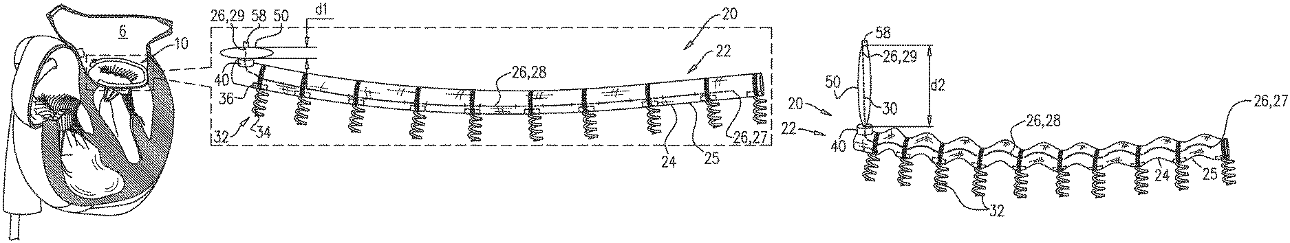
System 20 can comprise an implant 22 that comprises an implant body 24, and the system is for adjustment of the implant body. The implant 22 and/or implant body 24 shown can take a variety of forms and those depicted in the various figures herein are merely exemplary. For some applications, and as generally described herein, implant body 24 can be an annuloplasty ring structure, annuloplasty/annulus adjustment structure, other annuloplasty device structure, or other cinchable/tensionable structure. Implant body 24 can comprise a flexible sleeve 25 that has a wall or circumferential wall (e.g., which can be made of a fabric, such as a polyethylene terephthalate fabric, e.g., Dacron.TM.) that circumscribes a longitudinal axis of the sleeve, thereby defining a longitudinal lumen. System 20 (e.g., implant 22 thereof) can further comprise an elongate member 26. Elongate member 26 can comprise one or more strands of metal or polymer, optionally coated with a low-friction coating, such as polytetrafluoroethylene (PTFE). Implant body 24 can be configured to be placed partially or completely around a cardiac valve annulus 10 (e.g., a mitral valve annulus, tricuspid valve annulus, etc.). Implant body 24 can be secured or anchored in place at the valve annulus in a variety of ways, including by suturing the implant body 24 to the valve annulus, e.g., by parachuting similar to a surgical annuloplasty ring or otherwise. Implant body 24 can be configured to be anchored in place using a plurality of (e.g., 5-20) tissue anchors 32. The tissue anchors 32 can have a variety of features, for example, each tissue anchor 32 can comprise a tissue-coupling element 34, and a tool-engaging head 36 fastened to one end of the tissue-coupling element. Following introduction of implant body 24 into the subject, each anchor 32 can be sequentially intracorporeally delivered into the lumen of the sleeve, and its tissue-coupling element 34 can be driven from the interior lumen or from one side through the circumferential wall and into tissue of the valve annulus, thereby anchoring the implant body 24 or sleeve to the valve annulus. After the implant 22 and/or implant body 24 are secured or anchored to the valve annulus, longitudinal contraction of implant body 24, facilitated by system 20, can be used to circumferentially tighten the valve annulus, thereby improving coaptation of the valve leaflets, and reducing regurgitation.
For some applications, the implant structure of implant body 24 can be, or share features with, mutatis mutandis, any of the implant structures described in one or more of the following publications, which are incorporated herein by reference. The relevant features of the system herein may be substituted for adjustment features in these references. For some applications, implant 22 is implanted as described in one or more of these publications, mutatis mutandis: PCT application publication WO 2010/128503 to Zipory et al. PCT application publication WO 2012/176195 to Gross et al. PCT application publication WO 2013/069019 to Sheps et al. PCT application publication WO 2014/064694 to Sheps et al. U.S. Pat. No. 8,926,696 to Miller et al. U.S. Pat. No. 8,353,956 to Miller et al.
FIGS. 1A-C illustrate a generalization of system 20. More specific embodiments are described with reference to later figures.
Implantable apparatus or system 20 can comprise a gripper 40 and a pouch 50 (e.g., an elastic pouch) or other container. Pouch 50 can have a first part 54 and a second part 56, and has a contracted state (see FIGS. 1A and 1C) toward which the pouch is biased (e.g., elastically biased, shape-memory biased, etc.). The pouch 50 can have one or multiple contracted states. In the contracted state, the pouch can be configured to define a contracted distance d1 between the first part and the second part. Pouch 50 can be reversibly stretchable into a stretched state (FIG. 1B) in which the pouch defines a stretched distance d2 between first part 54 and second part 56. Distance d1 is smaller than distance d2. For example, distance d1 may be 1-12 mm (e.g., 1-7 mm, such as 2-6 mm), whereas distance d2 may be 20-100 mm (e.g., 30-80 mm, such as 40-70 mm).
Implantable apparatus or system 20 can also include an elongate member 26 that can extend into the pouch 50. Elongate member can be arranged such that it extends through a gripper 40, and then into pouch 50 via an opening 52. Opening 52 can be defined by second part 56 of the pouch. A first end portion 27 of elongate member 26 can be coupled to implant body 24. A second end portion 29 of elongate member 26 can be fastened to first part 54 of the pouch. Second part 56 can be defined by the location of opening 52, and first part 54 can be defined by the location of the fastening of elongate member 26 to pouch 50.
A third portion or mid-portion 28 of elongate member 26 can be between end portions 27 and 29. Mid-portion or third portion 28 can extend through gripper 40. Gripper 40 is configured (i) to facilitate tensioning of the elongate member, and (ii) to subsequently maintain the tension on the elongate member. As described in more detail hereinbelow, gripper 40 can have at least one state in which third portion or mid-portion 28 is slidable through the gripper and into pouch 50 via opening 52. For example, gripper 40 may facilitate one-way sliding of portion 28 therethrough. Alternatively or additionally, gripper 40 can have (i) an unlocked state in which it facilitates sliding of portion 28 therethrough, and (ii) a locked state in which it inhibits the sliding of the third portion or mid-portion.
Implantable apparatus or system 20 can also comprise an implant 22. FIG. 1A shows implant 22 subsequent to its implantation, and before its adjustment (i.e., contraction). Pouch 50 is shown in a contracted state (e.g., relaxed state). FIG. 1B shows pouch 50 having been reversibly stretched into a stretched state. Because second end portion 29 is fastened to first part 54, this stretching pulls on elongate member 26, drawing it (e.g., third portion or mid-portion 28 thereof) through gripper 40 and opening 52, into pouch 50, thereby longitudinally contracting implant body 24, e.g., by reducing the length of the elongate member disposed within the implant body. For applications in which implant body 24 is an annuloplasty ring structure or other annuloplasty device structure implanted around the valve annulus (e.g., all or a portion thereof), this longitudinal contraction circumferentially tightens the valve annulus, thereby improving coaptation of the valve leaflets, and reducing or eliminating regurgitation. It is to be understood that, during this step, gripper 40 can be in at least one state in which portion 28 is slidable through the gripper and into pouch 50 via opening 52. Optionally, pouch 50 and gripper 40 can be integral with or separate from implant 22. The implants or implant bodies described herein can have an open or closed (e.g., a closed ring) configuration and can be configured for transvascular or transcatheter implantation and/or surgical implantation.
FIG. 1B does not show how pouch 50 is stretched. Some examples of techniques for stretching pouch 50 are described in further detail hereinbelow. However, FIG. 1B does show a coupling 58 via which a tool is couplable to pouch 50 for stretching (e.g., pulling on) the pouch. For some applications, and as shown throughout this patent application, second end portion 29 of elongate member 26 can be fastened to first part 54 of pouch 50 by being fastened to coupling 58. The position of coupling 58 may thereby define or be first part 54 of pouch 50.
Subsequently, pouch 50 is allowed to return toward its contracted state (FIG. 1C), but gripper 40 can be designed or configured to inhibit or prevent elongate member 26 from sliding back through gripper 40 and into implant body 24. For example, and as described hereinbelow, gripper 40 may only facilitate one-way movement of member 26 therethrough, or may have been locked subsequently to the stretching of pouch 50. Because elongate member 26 is inhibited or prevented from sliding back through gripper 40, implant body 24 remains in its reduced length, and the valve annulus remains at its repaired size.
For some applications, pouch 50 can be made from or comprise an elastomer. For some applications, pouch 50 can comprise one or more strands of elastic and/or shape memory material such as Nitinol, e.g., optionally, threaded into the pouch so as to provide the pouch with its elastic nature.
Pouch 50 is typically distinct from an inflatable balloon. For some applications, pouch 50 can be partially permeable, allowing blood (or components thereof) to enter the pouch over time, and facilitating dotting and/or tissue growth therein. It is believed that this may facilitate maintenance of the tension applied to elongate member 26, and thereby maintenance of the contraction of implant body 24.
For some applications, pouch 50 can be impermeable to blood and/or components thereof. It is believed that this may facilitate readjustment of implant 22 subsequent to its implantation and initial contraction.
While a pouch might not be used, the pouch is beneficial to contain and restrict movement of any excess portion of the elongate member. For example, in the absence of pouch 50 (e.g., adjustment by pulling directly on end portion 29), the resulting excess 30 of elongate member 26 outside of implant body 24 may disadvantageously move freely within the body (e.g., within left atrium 6), with potentially deleterious effects. The elastic return of pouch 50 to its contracted state can compress excess 30 of elongate member 26, such that it is tidily confined. It is believed that this can advantageously avoid excess 30 being free within the heart, while obviating a potential need to remove (e.g., by cutting) excess 30.
For some applications, pouch 50, gripper 40, and implant body 24 can be coupled together such that, from proximal end portion 29, until at least implant body 24, elongate member 26 is not exposed to the body of the subject. That is, the pouch and gripper isolate the elongate member from the body of the subject. For some applications, more distal portions of elongate member 26 are exposed to the body of the subject, e.g., if elongate member 26 weaves in and out of implant body 24 (e.g., the circumferential wall of sleeve 25).
Although system 20 is generally described herein as including implant 22, it is to be noted that the scope of the invention does not require the system 20 to include the implant or any other component. For example, system 20 may be provided alone or unattached or uncombined with an implant, such that it can be later attached to and/or used with a different implant, e.g., a third-party implant. In one embodiment, system 20 can comprise pouch 50, gripper 40, elongate member 26, and one or more anchors attached to the elongate member, e.g., without a separate implant body.
Reference is made to FIGS. 2A-D and 3A-D, which are schematic illustrations of exemplary embodiments of adjustment-facilitating tool 60 being used with system 20 to adjust (e.g., contract) implant 22, in accordance with some applications of the invention. Various embodiments of tool 60 can comprise a tensioning element 62, and/or can comprise a pressing element 64.
The use of common reference numerals is intended to indicate commonality between elements of different embodiments, e.g., whereby an element of one embodiment serves the same primary function as the corresponding element of another embodiment. Suffixes (e.g., a, b, etc.) are used to uniquely identify the elements of a particular embodiment. For example, the embodiments of FIGS. 2A-D and 3A-D are depicted as each including a tool 60 (tools 60a and 60b, respectively) that comprises a tensioning element 62 (elements 62a and 62b). Despite the described differences between tools 60a and 60b, and between elements 62a and 62b, both tools are used to contract their respective implant 22, and both tensioning elements are coupled to their respective pouch 50, and are used to apply a proximally-directed force to (i.e., to pull on) the pouch to stretch it.
FIGS. 2A-D show an exemplary embodiment in which a tool 60a (an embodiment of tool 60) comprises a tensioning element 62a (an embodiment of tensioning element 62) and a pressing element 64a (an embodiment of pressing element 64), and an implant 22a (which can be the same as or similar to implant 22 or can be any implant that requires cinching or tightening from a remote or removed location) comprises a gripper 40a (an embodiment of gripper 40), an elastic pouch 50a (an embodiment of pouch 50), and a coupling 58a (an embodiment of coupling 58).
For some applications, implant 22 (e.g., implant 22a) can be delivered and implanted while at least part of tool 60 (e.g., tool 60a) is coupled to the implant. For example, implant 22a can be delivered and implanted while (i) tensioning element 62a is coupled to coupling 58a, and (ii) pressing element 64a abuts implant body 24. Alternatively, implant 22a can be delivered and implanted while (i) tensioning element 62a is coupled to coupling 58a, and (ii) pressing element 64a is proximal to the implant (e.g., within a delivery catheter or outside of the subject), and is subsequently advanced over and along the tensioning element to the implant. Optionally, another arrangement could also be used.
For some applications, implant 22 (e.g., implant 22a) is delivered and implanted without tool 60 (e.g., tool 60b) coupled to the implant, and one or more components of the tool are subsequently advanced to the implant (e.g., over and along a dedicated guide wire or guide member) and coupled to the implant, e.g., as described with reference to FIGS. 4A-D, mutatis mutandis.
While tensioning element 62a is coupled to coupling 58a, the tensioning element can be pulled proximally to reversibly stretch pouch 50a. Stretching the pouch can draw elongate member 26 (e.g., portion 28 thereof) through gripper 40a and into the pouch (FIG. 2B). This can be performed while pressing element 64 provides an opposing force against implant 22 (e.g., against implant body 24) in order that the pulling not pull the implant away from the tissue at which it is implanted. Pressing element 64a can be tubular and/or configured in a variety of shapes. Pressing element 64a can be disposed around tensioning element 62a (e.g., coaxially). Pressing element 64a or at least at its distal end can be wider than pouch 50a, such that it can press against the implant without interfering with the stretching of the pouch. Optionally, the pressing element could be configured to pass to one or more sides of the pouch to contact the implant, e.g., without surrounding the pouch.
After the implant and/or implant body 24 has been sufficiently contracted--which can be determined by imaging of the implant (e.g., using fluoroscopy, etc.), the anatomy, and/or blood flow (e.g., using echocardiography, ultrasound, etc.)--pouch 50a can be allowed to return to its contracted state (FIG. 2C). Gripper 40a can be configured to inhibit elongate member 26 from sliding back through the gripper and into implant body 24. For example, the gripper 40a and/or other grippers described herein can have friction resistance, a latch, valve, clamp, etc. that can allow movement of the member in one direction, but not the other direction. Tool 60a can be decoupled from implant 22a (e.g., element 62a can be decoupled from coupling 58a), and withdrawn from the subject (FIG. 2D). For some applications, and as shown, pouch 50a is allowed to return to its contracted state by moving element 62a distally, and/or by releasing tension on element 62a such that the elastically-contracting pouch pulls element 62a distally. For some applications, pouch 50a is allowed to return to its contracted state by decoupling tool 60a, including moving element 62a, from implant 22a, e.g., skipping the step shown in FIG. 2C.
FIGS. 3A-D show an embodiment in which a tool 60b (an embodiment of tool 60) comprises a tensioning element 62b (an embodiment of tensioning element 62) and a pressing element 64b (an embodiment of pressing element 64), and an implant 22b (e.g., the same as or similar to implant 22, 22a or any implant that needs to be contracted or tensioned) comprises a gripper 40b (an embodiment of gripper 40), an elastic pouch 50b (an embodiment of pouch 50), and a coupling 58b (an embodiment of coupling 58).
For some applications, implant 22b is delivered and implanted while at least part of tool 60b is coupled to the implant. For example, implant 22b can be delivered and implanted while tensioning element 62b is coupled to coupling 58b. Optionally, implant 22a can be delivered and implanted while (i) pressing element 64b is coupled to the implant (e.g., to gripper 40b thereof), and (ii) tensioning element 62b is proximal to the implant (e.g., within a delivery catheter or outside of the subject), and is subsequently advanced over and along the pressing element to the implant.
For some applications, implant 22b is delivered and implanted without tool 60b coupled to the implant, and one or more components of the tool are subsequently advanced to the implant (e.g., over and along a dedicated guide wire or guide member) and coupled to the implant, e.g., as described with reference to FIGS. 4A-D, mutatis mutandis.
While tensioning element 62b is coupled to coupling 58b, the tensioning element can be pulled proximally to reversibly stretch pouch 50b. Stretching pouch 50b can draw elongate member 26 (e.g., portion 28 thereof) through gripper 40b and into the pouch (FIG. 3B). This can be performed while pressing element 64b provides an opposing force against implant 22b in order that the pulling not pull the implant away from the tissue at which it is implanted. In contrast to the arrangement of elements 62a and 64a as shown in FIGS. 2A-2D, tensioning element 62b is depicted as being tubular and disposed around pressing element 64b (e.g., coaxially). Pressing element 64b can be configured and arranged to extend distally from tensioning element 62b, and through pouch 50b, e.g., such that is abuts and presses against the inner surface of the pouch and/or against gripper 40b, and such that it can provide the opposing force without interfering with the stretching of the pouch. Coupling 58b can be shaped to define an opening through which pressing element 64b extends or can extend into pouch 50b. When pouch 50b is stretched, coupling 58b can slide proximally along pressing element 64b.
After the implant 22 and/or implant body 24 has been sufficiently contracted, pouch 50b is allowed to return to its contracted state (FIG. 3C). Gripper 40b can be the same as or similar to other grippers described herein and can be configured to inhibit elongate member 26 from sliding back through the gripper and into implant body 24. Tool 60b can be decoupled from implant 22b (e.g., element 62b can be decoupled from coupling 58b), and withdrawn from the subject (FIG. 3D). For some applications, and as shown, pouch 50b can be allowed to return to its contracted state by moving element 62b distally, and/or by releasing tension on element 62b such that the elastically-contracting pouch pulls element 62b distally. For some applications, pouch 50b is allowed to return to its contracted state by decoupling tool 60b, including element 62b, from implant 22b, e.g., skipping the step shown in FIG. 3C.
For some applications, pressing element 64 maintains the coupling between tensioning element 62 and coupling 58. For example, with reference to FIGS. 3A-D, the presence of pressing element 64b within coupling 58b may hold a detent 66 defined by tensioning element 62b within a recess 68 defined by coupling 58b (or a detent defined by the coupling within a recess defined by the tensioning element). For example, the pressing element and/or detent can be configured or designed such that, upon removal of the pressing element, the detent automatically retracts from the recess, decoupling the tensioning element from the coupling.
Reference is again made to FIGS. 2A-D and 3A-D. Optionally, tool 60 can comprise an extracorporeal controller (not shown), which can comprise at least one handle, at the proximal end of elements 62 and 64. For some applications, the length of elongate member 26 (e.g., of portion or mid-portion 28) that slides proximally through gripper 40 and into pouch 50 is proportional (e.g., equal) to the amount by which implant body 24 contracts. Therefore, for some applications, the length by which implant body 24 contracts can be proportional (e.g., equal) to the distance moved by tensioning element 62 relative to pressing element 64. For some such applications, the amount of contraction of implant body 24 can be indicated by control members of the extracorporeal controller. For example, actuation of a control member (e.g., turning of one or more knobs) may cause movement between elements 62 and 64, and the amount that the control member has been actuated (e.g., the amount that the one or more knobs have been turned) can be indicated by a dial. For example, thereby indicating the amount of relative movement between elements 62 and 64, and thereby the amount of contraction of implant body 24.
Reference is now made to FIGS. 4A-D, which are schematic illustrations of the use of a guide member 70 (e.g., which can be a guide wire or other guide) to advance adjustment-facilitating tool 60 to implant 22 and/or to pouch 50, in accordance with some applications of the invention. For some applications, the implant can be implanted without an adjustment tool (e.g., tool 60) coupled thereto, and the tool can be subsequently advanced to the implant in order to adjust the implant. For such applications, implant 22 can be implanted with a guide member 70 coupled thereto (FIG. 4A). Subsequent to implantation, tool 60 can be advanced along (optionally over) guide member 70 (FIG. 4B), then tensioning element 62 can be coupled to pouch 50 (e.g., via coupling 58). Tool 60 can then be used to adjust implant 22 (e.g., to longitudinally contract the implant), e.g., by reversibly stretching pouch 50 (FIG. 4C). Pouch 50 can then be allowed to return to its contracted state, and tool 60 can be decoupled from implant 22 (FIG. 4D). As shown, guide member 70 can be decoupled from implant 22 subsequent to adjustment of the implant. This can be achieved by any suitable technique, such as unscrewing, unlocking a lock, etc., and can be performed using tool 60.
For some applications, guide member 70 is coupled to implant 22 at coupling 58. For some applications, guide member 70 is coupled to implant 22 at gripper 40 (e.g., as described with reference to FIGS. 6A-B). For some such applications, guide member 70 extends through pouch 50 to gripper 40. Other coupling options are also possible.
Reference is now made to FIGS. 5, 6A-B, and 7A-B which are schematic illustrations of exemplary embodiments of gripper 40. As described hereinabove, gripper 40 can allow for unidirectional movement/sliding or have at least one state in which third portion or mid-portion 28 of elongate member 26 is slidable through the gripper and into pouch 50 via opening 52. The gripper 40 can be configured such that the portion 28 and/or elongate member 26 is not slidable from the pouch back in to the implant. For example, gripper 40 may facilitate only one-way sliding of portion 28 therethrough. Optionally, it is also possible to configure gripper 40 to allow movement or sliding of the portion 28 and/or elongate member 26 into and out of the gripper 40 in both directions until the gripper is locked, clamped, or otherwise secured to prevent movement or sliding of the portion 28 and/or elongate member 26 therethrough. For example, gripper 40 may have (i) an unlocked state in which it facilitates sliding of portion 28 therethrough, and (ii) a locked state in which it inhibits the sliding of the portion/mid-portion.
FIG. 5 shows an exemplary embodiment 80 of gripper 40, which has a unidirectional state in which the gripper facilitates one-way sliding of portion 28 therethrough. Gripper 80 can comprise one or more wheels 82, each wheel comprising a gripping surface 84 (e.g., comprising a plurality of teeth or comprising other frictional element(s)) that can grip portion 28. Wheels 82 can be configured to rotate in only one rotational direction, and thereby facilitate movement of portion 28 in a first direction through the gripper into pouch 50, but not in a second direction through the gripper out of the pouch. For example, gripper 80 may comprise a pawl 86 that allows rotation of wheel 82 in only one rotational direction. Optionally, the one or more wheels could be configured to allow rotation in both directions until locked or secured to prevent further movement.
FIGS. 6A and 6B show an exemplary embodiment 100 of gripper 40 in which the gripper has (i) an unlocked state in which it facilitates sliding of portion 28 in either direction therethrough, and (ii) a locked state in which it inhibits the sliding of the portion in either direction. Optionally, the gripper can be biased to assume the locked state.
For some applications, gripper 100 can comprise at least one locking element 102 (e.g., a jaw, latch, contact edge, etc.) that, in the locked state, clamps onto portion 28 or elongate member 26. The jaw 102 (or other locking element) can have a gripping surface 104, such as one or more teeth or other frictional feature(s), that frictionally engages or grips portion 28 when the locking element or jaw contacts or clamps onto the portion of elongate member 26.
The system can also comprise an unlocker 110, which can be configured to maintain the gripper in an unlocked state. Optionally, gripper 100 can be configured to automatically transition into a locked state upon removal of unlocker 110 from the gripper. As shown, for example, in FIGS. 6A and 6B, unlocker 110 can be shaped to define a partial tube that inhibits (e.g., obstructs) jaw 102 (or other locking element) from clamping on to portion 28 and allows the portion to slide through the cavity defined by the partial tube. Because the unlocker defines only a partial tube, it is not threaded onto elongate member 26, and can therefore be removed from the implant after the gripper is locked. Unlocker 110 thereby serves as an actuator of gripper 100 (e.g., of jaw 102 thereof), via which the gripper is transitionable between its unlocked and locked states.
For some applications, and as shown, unlocker 110 can be defined by, or can be coupled to, the distal end of guide member 70. For such applications, guide member 70 can continue distally past coupling 58 and into pouch 50. Optionally, unlocker 110 can be distinct from guide member 70, and/or can be used in systems that do not include guide member 70.
FIGS. 7A and 7B show another exemplary embodiment 120 of gripper 40 in which the gripper has (i) an unlocked state in which it facilitates sliding of portion 28 in either direction therethrough, and (ii) a locked state in which it inhibits the sliding of the portion in either direction. Gripper 120 is typically identical to gripper 100 except where noted.
Gripper 120 is configured to be transitioned between its locked and unlocked states via an unlocker 130, which thereby serves as an actuator of gripper 120 (e.g., of jaw 102 thereof). In contrast to unlocker 110, unlocker 130 actuates gripper 120 by pulling on jaw 102, thereby pulling the jaw away from mid-portion 28 of elongate member 26. Unlocker 130 is reversibly coupled to jaw 102, such that when the unlocker is pulled proximally (e.g., tensioned), the jaw is opened, thereby transitioning the gripper into its unlocked state. The gripper can be biased to assume the locked state (e.g., in the absence of pulling by unlocker 130).
For some applications, and as shown, unlocker 130 comprises a filament (e.g., a wire or suture), and is reversibly coupled to jaw 102 by being looped around part of the jaw. For example, and as shown, the filament may be coupled to the jaw by being looped through an eyelet 122 that is coupled to or defined by the jaw. For some such applications, both ends of the filament are disposed outside of the heart (e.g., outside of the subject), and the unlocker is tensioned by pulling on both ends. For some such applications, decoupling of the unlocker from the gripper is achieved by releasing one end of the filament and pulling on the other end of the filament, causing the released end to travel toward the jaw and through the eyelet, thereby unthreading the filament from the eyelet.
For some applications, and as shown, unlocker 130 (e.g., proximal portions thereof) also serve as guide member 70, e.g., as described hereinabove, mutatis mutandis. This may alternatively be viewed as the unlocker being defined at a distal end of the guide member.
The use of unlocker 130 allows gripper 120 to be reversibly locked (e.g., locked, unlocked, and relocked), thereby further facilitating controlled contraction of the implant.
Other grippers described or shown herein can also include an unlocker, for example, gripper 80 can also have an unlocked state, and can be provided with an unlocker that inhibits wheels 82 from engaging portion 28 in one position and can be moved to another position to allow wheels 82 to engage portion 28.
The gripper 40 is not limited to what has been particularly shown and described hereinabove. For example, although gripping surfaces 84 and 104 are both shown as comprising teeth, other gripping surfaces (e.g., high friction surfaces) may be used. For some applications, the gripper can comprise a radially-contracting element (e.g., a helical spring) that is configured to grip the elongate member by being biased to radially contract, e.g., upon removal of an unlocker.
Grippers 40, 80, 100, and 120 etc. can be used in combination with any of the implants described herein, mutatis mutandis. For example, gripper 40a of implant 22a, or gripper 40b of implant 22b, can comprise gripper 80, 100, 120, or another gripper, mutatis mutandis. The grippers may alternatively or additionally be used to facilitate tensioning of, and/or maintenance of tension on, elongate members of other implants, including implants that do not comprise pouch 50. Such implants include adjustable annuloplasty bands, adjustable annuloplasty rings, and adjustable prosthetic chordae tendineae.
The present invention is not limited to what has been particularly shown and described hereinabove. Rather, the scope of the present invention includes both combinations and subcombinations of the various features described hereinabove, as well as variations and modifications thereof that are not in the prior art, which would occur to persons skilled in the art upon reading the foregoing description. Methods can include steps described above in various orders and combinations. Features and characteristics of one embodiment can be combined or incorporated into other embodiments.
* * * * *
D00000
D00001
D00002
D00003
D00004
D00005
D00006
D00007
XML
uspto.report is an independent third-party trademark research tool that is not affiliated, endorsed, or sponsored by the United States Patent and Trademark Office (USPTO) or any other governmental organization. The information provided by uspto.report is based on publicly available data at the time of writing and is intended for informational purposes only.
While we strive to provide accurate and up-to-date information, we do not guarantee the accuracy, completeness, reliability, or suitability of the information displayed on this site. The use of this site is at your own risk. Any reliance you place on such information is therefore strictly at your own risk.
All official trademark data, including owner information, should be verified by visiting the official USPTO website at www.uspto.gov. This site is not intended to replace professional legal advice and should not be used as a substitute for consulting with a legal professional who is knowledgeable about trademark law.