Stents for prosthetic heart valves
Tabor , et al. November 3, 2
U.S. patent number 10,820,993 [Application Number 16/714,091] was granted by the patent office on 2020-11-03 for stents for prosthetic heart valves. This patent grant is currently assigned to Medtronic, Inc.. The grantee listed for this patent is Medtronic, Inc.. Invention is credited to Carol E. Eberhardt, Brian A. Glynn, Timothy G. Laske, Joseph C. Morrow, Anne L. Brody Rubin, Timothy R. Ryan, Charles Tabor, Tammy Y. Tam, Michael J. Tuchek.


View All Diagrams
| United States Patent | 10,820,993 |
| Tabor , et al. | November 3, 2020 |
Stents for prosthetic heart valves
Abstract
A stented valve including a generally tubular stent structure that has a longitudinal axis, first and second opposite ends, a plurality of commissure support structures spaced from the first and second ends and extending generally parallel to the longitudinal axis, at least one structural wire positioned between each two adjacent commissure support structures, and at least one wing portion extending from two adjacent commissure support structures and toward one of the first and second ends of the stent structure. The stented valve further includes a valve structure attached within the generally tubular stent structure to the commissure support structures.
| Inventors: | Tabor; Charles (St. Louis Park, MN), Eberhardt; Carol E. (Fullerton, CA), Laske; Timothy G. (Shoreview, MN), Ryan; Timothy R. (Shorewood, MN), Morrow; Joseph C. (Eden Prairie, MN), Tam; Tammy Y. (San Francisco, CA), Glynn; Brian A. (Santa Rosa, CA), Rubin; Anne L. Brody (San Francisco, CA), Tuchek; Michael J. (Berwyn, IL) | ||||||||||
|---|---|---|---|---|---|---|---|---|---|---|---|
| Applicant: |
|
||||||||||
| Assignee: | Medtronic, Inc. (Minneapolis,
MN) |
||||||||||
| Family ID: | 1000005154558 | ||||||||||
| Appl. No.: | 16/714,091 | ||||||||||
| Filed: | December 13, 2019 |
Prior Publication Data
| Document Identifier | Publication Date | |
|---|---|---|
| US 20200113684 A1 | Apr 16, 2020 | |
Related U.S. Patent Documents
| Application Number | Filing Date | Patent Number | Issue Date | ||
|---|---|---|---|---|---|
| 16031019 | Jul 10, 2018 | ||||
| 15099125 | Jul 10, 2018 | 10016274 | |||
| 14163842 | May 17, 2016 | 9339382 | |||
| 13112656 | Mar 18, 2014 | 8673000 | |||
| 12321760 | Jul 5, 2011 | 7972378 | |||
| 61075902 | Jun 26, 2008 | ||||
| 61062207 | Jan 24, 2008 | ||||
| Current U.S. Class: | 1/1 |
| Current CPC Class: | A61F 2/013 (20130101); A61F 2/07 (20130101); A61F 2/2418 (20130101); A61F 2/915 (20130101); A61F 2/2433 (20130101); A61F 2230/0006 (20130101); A61F 2002/016 (20130101); A61F 2230/008 (20130101); A61F 2230/0054 (20130101); A61F 2220/0058 (20130101); A61F 2220/0091 (20130101); A61F 2250/003 (20130101); A61F 2/2436 (20130101); A61F 2250/0039 (20130101); A61F 2/90 (20130101); A61F 2/89 (20130101); A61F 2250/0018 (20130101); A61F 2220/0075 (20130101) |
| Current International Class: | A61F 2/24 (20060101); A61F 2/01 (20060101); A61F 2/07 (20130101); A61F 2/89 (20130101); A61F 2/915 (20130101); A61F 2/90 (20130101) |
| Field of Search: | ;623/2.1-2.19 |
References Cited [Referenced By]
U.S. Patent Documents
| 3334629 | August 1967 | Cohn |
| 3409013 | November 1968 | Berry |
| 3540431 | November 1970 | Mobin-Uddin |
| 3587115 | June 1971 | Shiley |
| 3628535 | December 1971 | Ostrowsky et al. |
| 3642004 | February 1972 | Osthagen et al. |
| 3657744 | April 1972 | Ersek |
| 3671979 | June 1972 | Moulopoulos |
| 3714671 | February 1973 | Edwards et al. |
| 3755823 | September 1973 | Hancock |
| 3795246 | March 1974 | Sturgeon |
| 3839741 | October 1974 | Haller |
| 3868956 | March 1975 | Alfidi et al. |
| 3874388 | April 1975 | King et al. |
| 4035849 | July 1977 | Angell et al. |
| 4056854 | November 1977 | Boretos et al. |
| 4106129 | August 1978 | Carpentier et al. |
| 4222126 | September 1980 | Boretos et al. |
| 4233690 | November 1980 | Akins |
| 4265694 | May 1981 | Boretos |
| 4291420 | September 1981 | Reul |
| 4297749 | November 1981 | Davis et al. |
| 4339831 | July 1982 | Johnson |
| 4343048 | August 1982 | Ross et al. |
| 4345340 | August 1982 | Rosen |
| 4425908 | January 1984 | Simon |
| 4470157 | September 1984 | Love |
| 4501030 | February 1985 | Lane |
| 4506394 | March 1985 | Debard |
| 4574803 | March 1986 | Storz |
| 4580568 | April 1986 | Gianturco |
| 4592340 | June 1986 | Boyles |
| 4610688 | September 1986 | Silvestrini et al. |
| 4612011 | September 1986 | Kautzky |
| 4647283 | March 1987 | Carpentier et al. |
| 4648881 | March 1987 | Carpentier et al. |
| 4655771 | April 1987 | Wallsten |
| 4662885 | May 1987 | DiPisa, Jr. |
| 4665906 | May 1987 | Jervis |
| 4681908 | July 1987 | Broderick et al. |
| 4710192 | December 1987 | Liotta et al. |
| 4733665 | March 1988 | Palmaz |
| 4777951 | October 1988 | Cribier et al. |
| 4787899 | November 1988 | Lazarus |
| 4796629 | January 1989 | Grayzel |
| 4797901 | January 1989 | Goerne et al. |
| 4819751 | April 1989 | Shimada et al. |
| 4834755 | May 1989 | Silvestrini et al. |
| 4856516 | August 1989 | Hillstead |
| 4872874 | October 1989 | Taheri |
| 4878495 | November 1989 | Grayzel |
| 4878906 | November 1989 | Lindemann et al. |
| 4883458 | November 1989 | Shiber |
| 4909252 | March 1990 | Goldberger |
| 4913141 | April 1990 | Hillstead |
| 4917102 | April 1990 | Miller et al. |
| 4922905 | May 1990 | Strecker |
| 4954126 | September 1990 | Wallsten |
| 4966604 | October 1990 | Reiss |
| 4979939 | December 1990 | Shiber |
| 4986830 | January 1991 | Owens et al. |
| 4994077 | February 1991 | Dobben |
| 5002559 | March 1991 | Tower |
| 5007896 | April 1991 | Shiber |
| 5026366 | June 1991 | Leckrone |
| 5032128 | July 1991 | Alonso |
| 5037434 | August 1991 | Lane |
| 5047041 | September 1991 | Samuels |
| 5059177 | October 1991 | Towne et al. |
| 5061273 | October 1991 | Yock |
| 5085635 | February 1992 | Cragg |
| 5089015 | February 1992 | Ross |
| 5152771 | October 1992 | Sabbaghian et al. |
| 5161547 | November 1992 | Tower |
| 5163953 | November 1992 | Vince |
| 5167628 | December 1992 | Boyles |
| 5217483 | June 1993 | Tower |
| 5232445 | August 1993 | Bonzel |
| 5272909 | December 1993 | Nguyen et al. |
| 5295958 | March 1994 | Shturman |
| 5327774 | July 1994 | Nguyen et al. |
| 5332402 | July 1994 | Teitelbaum et al. |
| 5350398 | September 1994 | Pavcnik et al. |
| 5370685 | December 1994 | Stevens |
| 5389106 | February 1995 | Tower |
| 5397351 | March 1995 | Pavcnik et al. |
| 5411552 | May 1995 | Andersen et al. |
| 5415633 | May 1995 | Lazarus et al. |
| 5431676 | July 1995 | Dubrul et al. |
| 5433723 | July 1995 | Lindenberg et al. |
| 5443446 | August 1995 | Shturman |
| 5443500 | August 1995 | Sigwart |
| 5449384 | September 1995 | Johnson |
| 5480424 | January 1996 | Cox |
| 5489294 | February 1996 | McVenes et al. |
| 5489297 | February 1996 | Duran |
| 5496346 | March 1996 | Horzewski et al. |
| 5500014 | March 1996 | Quijano et al. |
| 5507767 | April 1996 | Maeda et al. |
| 5545209 | August 1996 | Roberts et al. |
| 5545211 | August 1996 | An et al. |
| 5545214 | August 1996 | Stevens |
| 5554185 | September 1996 | Block et al. |
| 5575818 | November 1996 | Pinchuk |
| 5580922 | December 1996 | Park et al. |
| 5591195 | January 1997 | Taheri et al. |
| 5609626 | March 1997 | Quijano et al. |
| 5645559 | July 1997 | Hachtman et al. |
| 5665115 | September 1997 | Cragg |
| 5667523 | September 1997 | Bynon et al. |
| 5674277 | October 1997 | Freitag |
| 5693083 | December 1997 | Baker et al. |
| 5695498 | December 1997 | Tower |
| 5702368 | December 1997 | Stevens et al. |
| 5713953 | February 1998 | Vallana et al. |
| 5716417 | February 1998 | Girard et al. |
| 5746709 | May 1998 | Rom et al. |
| 5749890 | May 1998 | Shaknovich |
| 5749921 | May 1998 | Lenker et al. |
| 5766151 | June 1998 | Valley et al. |
| 5776142 | July 1998 | Gunderson |
| 5782809 | July 1998 | Umeno et al. |
| 5800455 | September 1998 | Palarmo et al. |
| 5800456 | September 1998 | Maeda et al. |
| 5800508 | September 1998 | Goicoechea et al. |
| 5807405 | September 1998 | Vanney et al. |
| 5817126 | October 1998 | Imran |
| 5824041 | October 1998 | Lenker |
| 5824043 | October 1998 | Cottone, Jr. |
| 5824053 | October 1998 | Khosravi et al. |
| 5824056 | October 1998 | Rosenberg |
| 5824061 | October 1998 | Quijano et al. |
| 5824064 | October 1998 | Taheri |
| 5840081 | November 1998 | Anderson et al. |
| 5843158 | December 1998 | Lenker et al. |
| 5851232 | December 1998 | Lois |
| 5855597 | January 1999 | Jayaraman |
| 5855601 | January 1999 | Bessler et al. |
| 5860966 | January 1999 | Tower |
| 5861028 | January 1999 | Angell |
| 5868783 | February 1999 | Tower |
| 5876448 | March 1999 | Thompson et al. |
| 5891191 | April 1999 | Stinson |
| 5906619 | May 1999 | Olson et al. |
| 5907893 | June 1999 | Zadno-Azizi et al. |
| 5913842 | June 1999 | Boyd et al. |
| 5925063 | July 1999 | Khosravi |
| 5944738 | August 1999 | Amplatz et al. |
| 5944750 | August 1999 | Tanner et al. |
| 5957949 | September 1999 | Leonhardt et al. |
| 5968068 | October 1999 | Dehdashtian et al. |
| 5984957 | November 1999 | Laptewicz, Jr. et al. |
| 5997573 | December 1999 | Quijano et al. |
| 6022370 | February 2000 | Tower |
| 6027525 | February 2000 | Suh et al. |
| 6029671 | February 2000 | Stevens et al. |
| 6042589 | March 2000 | Marianne |
| 6042598 | March 2000 | Tsugita et al. |
| 6042607 | March 2000 | Williamson, IV |
| 6051014 | April 2000 | Jang |
| 6059809 | May 2000 | Amor et al. |
| 6110201 | August 2000 | Quijano et al. |
| 6146366 | November 2000 | Schachar |
| 6159239 | December 2000 | Greenhalgh |
| 6162208 | December 2000 | Hipps |
| 6162245 | December 2000 | Jayaraman |
| 6168614 | January 2001 | Anderson et al. |
| 6168616 | January 2001 | Brown, III |
| 6168618 | January 2001 | Frantzen |
| 6171335 | January 2001 | Wheatley et al. |
| 6200336 | March 2001 | Pavcnik et al. |
| 6203550 | March 2001 | Olson |
| 6210408 | April 2001 | Chandrasekaran et al. |
| 6218662 | April 2001 | Tchakarov et al. |
| 6221006 | April 2001 | Dubrul et al. |
| 6221091 | April 2001 | Khosravi |
| 6241757 | June 2001 | An et al. |
| 6245102 | June 2001 | Jayaraman |
| 6248116 | June 2001 | Chevilon |
| 6258114 | July 2001 | Konya et al. |
| 6258115 | July 2001 | Dubrul |
| 6258120 | July 2001 | McKenzie et al. |
| 6277555 | August 2001 | Duran et al. |
| 6299637 | October 2001 | Shaolia et al. |
| 6302906 | October 2001 | Goicoechea et al. |
| 6309382 | October 2001 | Garrison et al. |
| 6309417 | October 2001 | Spence et al. |
| 6338735 | January 2002 | Stevens |
| 6346118 | February 2002 | Baker et al. |
| 6348063 | February 2002 | Yassour et al. |
| 6350277 | February 2002 | Kocur |
| 6352708 | March 2002 | Duran et al. |
| 6371970 | April 2002 | Khosravi et al. |
| 6371979 | April 2002 | Beyar et al. |
| 6371983 | April 2002 | Lane |
| 6379383 | April 2002 | Palmaz et al. |
| 6380457 | April 2002 | Yurek et al. |
| 6398807 | June 2002 | Chouinard et al. |
| 6409750 | June 2002 | Hyodoh et al. |
| 6425916 | July 2002 | Garrison et al. |
| 6440164 | August 2002 | DiMatteo et al. |
| 6454799 | September 2002 | Schreck |
| 6458153 | October 2002 | Bailey et al. |
| 6461382 | October 2002 | Cao |
| 6468303 | October 2002 | Amplatz et al. |
| 6475239 | November 2002 | Campbell et al. |
| 6482228 | November 2002 | Norred |
| 6488704 | December 2002 | Connelly et al. |
| 6494909 | December 2002 | Greenhalgh |
| 6503272 | January 2003 | Duerig et al. |
| 6508833 | January 2003 | Pavcnik et al. |
| 6517548 | February 2003 | Lorentzen et al. |
| 6527800 | March 2003 | McGuckin, Jr. et al. |
| 6530949 | March 2003 | Konya et al. |
| 6530952 | March 2003 | Vesely |
| RE38091 | April 2003 | Strecker |
| 6562031 | May 2003 | Chandrasekaran et al. |
| 6562058 | May 2003 | Seguin et al. |
| 6569196 | May 2003 | Vesely |
| 6582460 | June 2003 | Cryer |
| 6585758 | July 2003 | Chouinard et al. |
| 6592546 | July 2003 | Barbut et al. |
| 6605112 | August 2003 | Moll et al. |
| 6613077 | September 2003 | Gilligan et al. |
| 6622604 | September 2003 | Chouinard et al. |
| 6635068 | October 2003 | Dubrul et al. |
| 6635079 | October 2003 | Unsworth et al. |
| 6652571 | November 2003 | White et al. |
| 6652578 | November 2003 | Bailey et al. |
| 6656213 | December 2003 | Solem |
| 6663663 | December 2003 | Kim et al. |
| 6666881 | December 2003 | Richter et al. |
| 6669724 | December 2003 | Park et al. |
| 6673089 | January 2004 | Yassour et al. |
| 6676698 | January 2004 | McGuckin, Jr. et al. |
| 6682559 | January 2004 | Myers et al. |
| 6685739 | February 2004 | DiMatteo et al. |
| 6689144 | February 2004 | Gerberding |
| 6689164 | February 2004 | Seguin |
| 6692512 | February 2004 | Jang |
| 6692513 | February 2004 | Streeter et al. |
| 6695878 | February 2004 | McGuckin, Jr. et al. |
| 6702851 | March 2004 | Chinn et al. |
| 6719789 | April 2004 | Cox |
| 6730118 | May 2004 | Spenser et al. |
| 6730377 | May 2004 | Wang |
| 6733525 | May 2004 | Yang et al. |
| 6736846 | May 2004 | Cox |
| 6752828 | June 2004 | Thornton |
| 6758855 | July 2004 | Fulton, III et al. |
| 6769434 | August 2004 | Liddicoat et al. |
| 6776791 | August 2004 | Stallings et al. |
| 6786925 | September 2004 | Schoon |
| 6790229 | September 2004 | Berreklouw |
| 6790230 | September 2004 | Beyersdorf et al. |
| 6792979 | September 2004 | Konya et al. |
| 6797002 | September 2004 | Spence |
| 6821297 | November 2004 | Snyders |
| 6830575 | December 2004 | Stenzel et al. |
| 6830584 | December 2004 | Seguin |
| 6830585 | December 2004 | Artof |
| 6846325 | January 2005 | Liddicoat |
| 6866650 | March 2005 | Stevens |
| 6866669 | March 2005 | Buzzard et al. |
| 6872223 | March 2005 | Roberts |
| 6875231 | April 2005 | Anduiza et al. |
| 6883522 | April 2005 | Spence et al. |
| 6887266 | May 2005 | Williams et al. |
| 6890330 | May 2005 | Streeter et al. |
| 6893460 | May 2005 | Spenser et al. |
| 6896690 | May 2005 | Lambrecht et al. |
| 6908481 | June 2005 | Cribier |
| 6913600 | July 2005 | Valley et al. |
| 6929653 | August 2005 | Streeter |
| 6936066 | August 2005 | Palmaz et al. |
| 6939365 | September 2005 | Fogarty et al. |
| 6951571 | October 2005 | Srivastava |
| 6974474 | December 2005 | Pavcnik et al. |
| 6974476 | December 2005 | McGuckin et al. |
| 6986742 | January 2006 | Hart et al. |
| 6989027 | January 2006 | Allen et al. |
| 6989028 | January 2006 | Lashinski et al. |
| 6991649 | January 2006 | Sievers |
| 7018401 | March 2006 | Hyodoh et al. |
| 7022132 | April 2006 | Kocur |
| 7041128 | May 2006 | McGuckin, Jr. et al. |
| 7044966 | May 2006 | Svanidze et al. |
| 7048014 | May 2006 | Hyodoh et al. |
| 7097659 | August 2006 | Woolfson et al. |
| 7101396 | September 2006 | Artof et al. |
| 7105016 | September 2006 | Shui et al. |
| 7115141 | October 2006 | Menz et al. |
| 7128759 | October 2006 | Osborne et al. |
| 7147663 | December 2006 | Berg et al. |
| 7153324 | December 2006 | Case et al. |
| 7160319 | January 2007 | Chouinard et al. |
| 7175656 | February 2007 | Khairkhahan |
| 7186265 | March 2007 | Sharkawy et al. |
| 7195641 | March 2007 | Palmaz et al. |
| 7198646 | April 2007 | Figulla et al. |
| 7201761 | April 2007 | Woolfson et al. |
| 7201772 | April 2007 | Schwammenthal et al. |
| 7252680 | August 2007 | Freitag |
| 7252682 | August 2007 | Seguin |
| 7300457 | November 2007 | Palmaz |
| 7300463 | November 2007 | Liddicoat |
| 7316706 | January 2008 | Bloom et al. |
| 7329278 | February 2008 | Seguin |
| 7335218 | February 2008 | Wilson et al. |
| 7338520 | March 2008 | Bailey et al. |
| 7374571 | May 2008 | Pease et al. |
| 7377938 | May 2008 | Sarac et al. |
| 7381218 | June 2008 | Shreck |
| 7384411 | June 2008 | Condado |
| 7429269 | September 2008 | Schwammenthal et al. |
| 7442204 | October 2008 | Schwammenthal et al. |
| 7462191 | December 2008 | Spenser et al. |
| 7470284 | December 2008 | Lambrecht et al. |
| 7481838 | January 2009 | Carpentier et al. |
| 7544206 | June 2009 | Cohn et al. |
| 7547322 | June 2009 | Sarac et al. |
| 7556646 | July 2009 | Yang et al. |
| 7569071 | August 2009 | Haverkost et al. |
| 7618447 | November 2009 | Case et al. |
| 7651521 | January 2010 | Ton et al. |
| 7682390 | March 2010 | Seguin |
| 7708775 | May 2010 | Rowe et al. |
| 7722666 | May 2010 | Lafontaine |
| 7771463 | August 2010 | Ton et al. |
| 7780726 | August 2010 | Seguin |
| 7785361 | August 2010 | Nikolchev et al. |
| 7806726 | August 2010 | Seguin |
| 7803177 | September 2010 | Hartley et al. |
| 7837643 | November 2010 | Levine et al. |
| 7857845 | December 2010 | Stacchino et al. |
| 7862602 | January 2011 | Licata et al. |
| 7959666 | June 2011 | Salahieh et al. |
| 7959672 | June 2011 | Salahieh et al. |
| 7972378 | July 2011 | Tabor |
| 7993394 | August 2011 | Hariton et al. |
| 8133270 | March 2012 | Kheradvar et al. |
| 8252052 | August 2012 | Salahieh et al. |
| 8343213 | January 2013 | Salahieh et al. |
| 8597349 | December 2013 | Alkhatib |
| 8603160 | December 2013 | Salahieh et al. |
| 8652202 | February 2014 | Alon et al. |
| 8673000 | March 2014 | Tabor |
| 8702788 | April 2014 | Kheradvar et al. |
| 8828078 | September 2014 | Salahieh et al. |
| 8840663 | September 2014 | Salahieh et al. |
| 9132024 | September 2015 | Brinser |
| 9168131 | October 2015 | Yohanan et al. |
| 9339382 | May 2016 | Tabor |
| 9393110 | July 2016 | Levi et al. |
| 9393115 | July 2016 | Tabor et al. |
| 10016274 | July 2018 | Tabor |
| 2001/0001314 | May 2001 | Davison et al. |
| 2001/0002445 | May 2001 | Vesely |
| 2001/0007956 | July 2001 | Letac et al. |
| 2001/0010017 | July 2001 | Letac et al. |
| 2001/0011189 | August 2001 | Drasler et al. |
| 2001/0021872 | September 2001 | Bailey et al. |
| 2001/0025196 | September 2001 | Chinn et al. |
| 2001/0032013 | October 2001 | Marton |
| 2001/0037142 | November 2001 | Stelter et al. |
| 2001/0039450 | November 2001 | Pavcnik et al. |
| 2001/0041928 | November 2001 | Pavcnik et al. |
| 2001/0044647 | November 2001 | Pinchuk et al. |
| 2001/0047150 | November 2001 | Chobotov |
| 2001/0049550 | December 2001 | Martin et al. |
| 2002/0010508 | January 2002 | Chobotov |
| 2002/0029014 | March 2002 | Jayaraman |
| 2002/0032480 | March 2002 | Spence et al. |
| 2002/0032481 | March 2002 | Gabbay |
| 2002/0035396 | March 2002 | Heath |
| 2002/0042650 | April 2002 | Vardi et al. |
| 2002/0052651 | May 2002 | Myers et al. |
| 2002/0058995 | May 2002 | Stevens |
| 2002/0065545 | May 2002 | Leonhardt et al. |
| 2002/0072789 | June 2002 | Hackett et al. |
| 2002/0091439 | July 2002 | Baker et al. |
| 2002/0095209 | July 2002 | Zadno-Azizi et al. |
| 2002/0099439 | July 2002 | Schwartz et al. |
| 2002/0103533 | August 2002 | Langberg et al. |
| 2002/0107565 | August 2002 | Greenhalgh |
| 2002/0111674 | August 2002 | Chouinard et al. |
| 2002/0120277 | August 2002 | Hauschild et al. |
| 2002/0123802 | September 2002 | Snyders |
| 2002/0133183 | September 2002 | Lentz et al. |
| 2002/0138138 | September 2002 | Yang |
| 2002/0151970 | October 2002 | Garrison et al. |
| 2002/0161392 | October 2002 | Dubrul |
| 2002/0161394 | October 2002 | Macoviak et al. |
| 2002/0188341 | December 2002 | Elliott |
| 2002/0193871 | December 2002 | Beyersdorf et al. |
| 2003/0004560 | January 2003 | Chobotov et al. |
| 2003/0014104 | January 2003 | Cribier |
| 2003/0023300 | January 2003 | Bailey et al. |
| 2003/0023303 | January 2003 | Palmaz et al. |
| 2003/0028247 | February 2003 | Cali |
| 2003/0036791 | February 2003 | Phillip et al. |
| 2003/0040771 | February 2003 | Hyodoh et al. |
| 2003/0040772 | February 2003 | Hyodoh et al. |
| 2003/0040792 | February 2003 | Gabbay |
| 2003/0050684 | March 2003 | Abrams et al. |
| 2003/0050694 | March 2003 | Yang et al. |
| 2003/0055495 | March 2003 | Pease et al. |
| 2003/0065386 | April 2003 | Weadock |
| 2003/0069492 | April 2003 | Abrams et al. |
| 2003/0109924 | June 2003 | Cribier |
| 2003/0125795 | July 2003 | Pavcnik et al. |
| 2003/0130726 | July 2003 | Thorpe et al. |
| 2003/0130729 | July 2003 | Paniagua et al. |
| 2003/0135257 | July 2003 | Taheri |
| 2003/0139804 | July 2003 | Hankh et al. |
| 2003/0149475 | August 2003 | Hyodoh et al. |
| 2003/0149476 | August 2003 | Damm et al. |
| 2003/0149478 | August 2003 | Figulla et al. |
| 2003/0153974 | August 2003 | Spenser et al. |
| 2003/0181850 | September 2003 | Diamond et al. |
| 2003/0191519 | October 2003 | Lombardi et al. |
| 2003/0199913 | October 2003 | Dubrul et al. |
| 2003/0199963 | October 2003 | Tower et al. |
| 2003/0199971 | October 2003 | Tower et al. |
| 2003/0199975 | October 2003 | Gabbay |
| 2003/0212410 | November 2003 | Stenzel et al. |
| 2003/0212454 | November 2003 | Scott et al. |
| 2003/0225445 | December 2003 | Derus et al. |
| 2003/0233140 | December 2003 | Hartley et al. |
| 2004/0034411 | February 2004 | Quijano et al. |
| 2004/0039436 | February 2004 | Spenser et al. |
| 2004/0049224 | March 2004 | Buehlmann et al. |
| 2004/0049262 | March 2004 | Obermiller et al. |
| 2004/0049266 | March 2004 | Anduiza et al. |
| 2004/0082904 | April 2004 | Houde et al. |
| 2004/0082989 | April 2004 | Cook et al. |
| 2004/0088045 | May 2004 | Cox |
| 2004/0092858 | May 2004 | Wilson et al. |
| 2004/0092989 | May 2004 | Wilson et al. |
| 2004/0093005 | May 2004 | Durcan |
| 2004/0093060 | May 2004 | Sequin et al. |
| 2004/0093075 | May 2004 | Kuehn |
| 2004/0097788 | May 2004 | Mourles et al. |
| 2004/0098112 | May 2004 | DiMatteo et al. |
| 2004/0106976 | June 2004 | Bailey et al. |
| 2004/0106990 | June 2004 | Spence et al. |
| 2004/0111096 | June 2004 | Tu et al. |
| 2004/0116951 | June 2004 | Rosengart |
| 2004/0117004 | June 2004 | Osborne et al. |
| 2004/0122468 | June 2004 | Yodfat et al. |
| 2004/0122514 | June 2004 | Fogarty et al. |
| 2004/0122516 | June 2004 | Fogarty |
| 2004/0127979 | July 2004 | Wilson |
| 2004/0138742 | July 2004 | Myers et al. |
| 2004/0138743 | July 2004 | Myers et al. |
| 2004/0153146 | August 2004 | Lashinski et al. |
| 2004/0167573 | August 2004 | Williamson |
| 2004/0167620 | August 2004 | Ortiz |
| 2004/0186514 | September 2004 | Swain et al. |
| 2004/0186563 | September 2004 | Iobbi |
| 2004/0193261 | September 2004 | Berreklouw |
| 2004/0210240 | October 2004 | Saint |
| 2004/0210304 | October 2004 | Seguin et al. |
| 2004/0210307 | October 2004 | Khairkhahan |
| 2004/0215333 | October 2004 | Duran |
| 2004/0215339 | October 2004 | Drasler et al. |
| 2004/0220655 | November 2004 | Swanson et al. |
| 2004/0225353 | November 2004 | McGuckin, Jr. |
| 2004/0225354 | November 2004 | Allen |
| 2004/0254636 | December 2004 | Flagle et al. |
| 2004/0260383 | December 2004 | Stelter et al. |
| 2004/0260389 | December 2004 | Case et al. |
| 2004/0260394 | December 2004 | Douk et al. |
| 2004/0267357 | December 2004 | Allen et al. |
| 2005/0010246 | January 2005 | Streeter |
| 2005/0010285 | January 2005 | Lambrecht et al. |
| 2005/0010287 | January 2005 | Macoviak |
| 2005/0015112 | January 2005 | Cohn et al. |
| 2005/0027348 | February 2005 | Case et al. |
| 2005/0033398 | February 2005 | Seguin |
| 2005/0043790 | February 2005 | Seguin |
| 2005/0049692 | March 2005 | Numamoto |
| 2005/0049696 | March 2005 | Siess |
| 2005/0055088 | March 2005 | Liddicoat et al. |
| 2005/0060029 | March 2005 | Le |
| 2005/0060030 | March 2005 | Lashinski et al. |
| 2005/0075584 | April 2005 | Cali |
| 2005/0075712 | April 2005 | Biancucci |
| 2005/0075717 | April 2005 | Nguyen |
| 2005/0075719 | April 2005 | Bergheim |
| 2005/0075724 | April 2005 | Svanidze |
| 2005/0075727 | April 2005 | Wheatley |
| 2005/0075730 | April 2005 | Myers |
| 2005/0075731 | April 2005 | Artof |
| 2005/0085841 | April 2005 | Eversull et al. |
| 2005/0085842 | April 2005 | Eversull et al. |
| 2005/0085843 | April 2005 | Opolski et al. |
| 2005/0085890 | April 2005 | Rasmussen et al. |
| 2005/0085900 | April 2005 | Case et al. |
| 2005/0096568 | May 2005 | Kato |
| 2005/0096692 | May 2005 | Linder et al. |
| 2005/0096724 | May 2005 | Stenzel et al. |
| 2005/0096734 | May 2005 | Majercak et al. |
| 2005/0096735 | May 2005 | Hojeibane et al. |
| 2005/0096736 | May 2005 | Osse et al. |
| 2005/0096738 | May 2005 | Cali et al. |
| 2005/0107871 | May 2005 | Realyvasquez et al. |
| 2005/0113910 | May 2005 | Paniagua |
| 2005/0119688 | June 2005 | Berheim |
| 2005/0131438 | June 2005 | Cohn |
| 2005/0137686 | June 2005 | Salahieh |
| 2005/0137688 | June 2005 | Salahieh et al. |
| 2005/0137689 | June 2005 | Salahieh et al. |
| 2005/0137690 | June 2005 | Salahieh et al. |
| 2005/0137692 | June 2005 | Haug |
| 2005/0137695 | June 2005 | Salahieh |
| 2005/0137697 | June 2005 | Salahieh et al. |
| 2005/0137698 | June 2005 | Salahieh et al. |
| 2005/0137699 | June 2005 | Salahieh et al. |
| 2005/0137701 | June 2005 | Salahieh |
| 2005/0143807 | June 2005 | Pavcnik et al. |
| 2005/0143809 | June 2005 | Salahieh |
| 2005/0148997 | July 2005 | Valley et al. |
| 2005/0149181 | July 2005 | Eberhardt |
| 2005/0165477 | July 2005 | Anduiza et al. |
| 2005/0187616 | August 2005 | Realyvasquez |
| 2005/0197695 | September 2005 | Stacchino et al. |
| 2005/0203549 | September 2005 | Realyvasquez |
| 2005/0203605 | September 2005 | Dolan |
| 2005/0203618 | September 2005 | Sharkawy |
| 2005/0222674 | October 2005 | Paine |
| 2005/0228495 | October 2005 | Macoviak |
| 2005/0234546 | October 2005 | Nugent |
| 2005/0240200 | October 2005 | Bergheim |
| 2005/0240263 | October 2005 | Fogarty et al. |
| 2005/0261759 | November 2005 | Lambrecht et al. |
| 2005/0283231 | December 2005 | Haug et al. |
| 2005/0283962 | December 2005 | Boudjemline |
| 2005/0288764 | December 2005 | Snow et al. |
| 2006/0004439 | January 2006 | Spenser et al. |
| 2006/0004469 | January 2006 | Sokel |
| 2006/0009841 | January 2006 | McGuckin et al. |
| 2006/0025857 | February 2006 | Bergheim et al. |
| 2006/0052867 | March 2006 | Revuelta et al. |
| 2006/0058775 | March 2006 | Stevens et al. |
| 2006/0089711 | April 2006 | Dolan |
| 2006/0095119 | May 2006 | Bolduc |
| 2006/0100685 | May 2006 | Seguin et al. |
| 2006/0111771 | May 2006 | Ton et al. |
| 2006/0116757 | June 2006 | Lashinski et al. |
| 2006/0122692 | June 2006 | Gilad et al. |
| 2006/0135964 | June 2006 | Vesely |
| 2006/0142848 | June 2006 | Gabbay |
| 2006/0149360 | July 2006 | Schwammenthal et al. |
| 2006/0167474 | July 2006 | Bloom et al. |
| 2006/0173524 | August 2006 | Salahieh et al. |
| 2006/0178740 | August 2006 | Stacchino |
| 2006/0195134 | August 2006 | Crittenden |
| 2006/0195184 | August 2006 | Lane et al. |
| 2006/0206192 | September 2006 | Tower et al. |
| 2006/0206202 | September 2006 | Bonhoefer et al. |
| 2006/0212111 | September 2006 | Case et al. |
| 2006/0241745 | October 2006 | Solem |
| 2006/0247763 | November 2006 | Slater |
| 2006/0259134 | November 2006 | Schwammenthal et al. |
| 2006/0259136 | November 2006 | Nguyen et al. |
| 2006/0259137 | November 2006 | Artof et al. |
| 2006/0265056 | November 2006 | Nguyen et al. |
| 2006/0271097 | November 2006 | Ramzipoor et al. |
| 2006/0271166 | November 2006 | Thill et al. |
| 2006/0271175 | November 2006 | Woolfson et al. |
| 2006/0276874 | December 2006 | Wilson et al. |
| 2006/0276882 | December 2006 | Case et al. |
| 2006/0282161 | December 2006 | Huynh et al. |
| 2007/0005129 | January 2007 | Damm et al. |
| 2007/0005131 | January 2007 | Taylor |
| 2007/0010878 | January 2007 | Raffiee et al. |
| 2007/0016286 | January 2007 | Case et al. |
| 2007/0027518 | February 2007 | Herrmann et al. |
| 2007/0027533 | February 2007 | Douk |
| 2007/0038295 | February 2007 | Case et al. |
| 2007/0043431 | February 2007 | Melsheimer |
| 2007/0043435 | February 2007 | Seguin et al. |
| 2007/0051377 | March 2007 | Douk et al. |
| 2007/0073392 | March 2007 | Heyninck-Janitz |
| 2007/0078509 | April 2007 | Lotfy et al. |
| 2007/0078510 | April 2007 | Ryan |
| 2007/0088431 | April 2007 | Bourang et al. |
| 2007/0093869 | April 2007 | Bloom et al. |
| 2007/0100419 | May 2007 | Licata et al. |
| 2007/0100435 | May 2007 | Case |
| 2007/0100439 | May 2007 | Cangialosi |
| 2007/0100440 | May 2007 | Figulla |
| 2007/0100449 | May 2007 | O'Neil et al. |
| 2007/0112415 | May 2007 | Bartlett |
| 2007/0112422 | May 2007 | Dehdashtian |
| 2007/0142907 | June 2007 | Moaddeb et al. |
| 2007/0162102 | July 2007 | Ryan et al. |
| 2007/0162113 | July 2007 | Sharkawy et al. |
| 2007/0185513 | August 2007 | Woolfson et al. |
| 2007/0203391 | August 2007 | Bloom et al. |
| 2007/0203503 | August 2007 | Salahieh et al. |
| 2007/0208550 | September 2007 | Cao et al. |
| 2007/0213813 | September 2007 | Von Segesser et al. |
| 2007/0225681 | September 2007 | House |
| 2007/0232898 | October 2007 | Huynh et al. |
| 2007/0233228 | October 2007 | Eberhardt et al. |
| 2007/0233237 | October 2007 | Krivoruchko |
| 2007/0233238 | October 2007 | Huynh et al. |
| 2007/0238979 | October 2007 | Huynh et al. |
| 2007/0239254 | October 2007 | Marchand et al. |
| 2007/0239265 | October 2007 | Birdsall |
| 2007/0239266 | October 2007 | Birdsall |
| 2007/0239269 | October 2007 | Dolan et al. |
| 2007/0239271 | October 2007 | Nguyen |
| 2007/0239273 | October 2007 | Allen |
| 2007/0244544 | October 2007 | Birdsall et al. |
| 2007/0244545 | October 2007 | Birdsall et al. |
| 2007/0244546 | October 2007 | Francis |
| 2007/0244553 | October 2007 | Rafiee et al. |
| 2007/0244554 | October 2007 | Rafiee et al. |
| 2007/0244555 | October 2007 | Rafiee et al. |
| 2007/0244556 | October 2007 | Rafiee et al. |
| 2007/0244557 | October 2007 | Rafiee et al. |
| 2007/0250160 | October 2007 | Rafiee |
| 2007/0255394 | November 2007 | Ryan |
| 2007/0255396 | November 2007 | Douk et al. |
| 2007/0255398 | November 2007 | Yang et al. |
| 2007/0288000 | December 2007 | Bonan |
| 2007/0288087 | December 2007 | Fearnot et al. |
| 2008/0004696 | January 2008 | Vesely |
| 2008/0009940 | January 2008 | Cribier |
| 2008/0015671 | January 2008 | Bonhoeffer |
| 2008/0021552 | January 2008 | Gabbay |
| 2008/0027529 | January 2008 | Hartley et al. |
| 2008/0048656 | February 2008 | Tan |
| 2008/0065011 | March 2008 | Marchand et al. |
| 2008/0065206 | March 2008 | Liddicoat |
| 2008/0071361 | March 2008 | Tuval et al. |
| 2008/0071362 | March 2008 | Tuval et al. |
| 2008/0071363 | March 2008 | Tuval et al. |
| 2008/0071366 | March 2008 | Tuval et al. |
| 2008/0071368 | March 2008 | Tuval et al. |
| 2008/0077234 | March 2008 | Styrc |
| 2008/0082159 | April 2008 | Tseng et al. |
| 2008/0082165 | April 2008 | Wilson et al. |
| 2008/0082166 | April 2008 | Styrec et al. |
| 2008/0133003 | June 2008 | Seguin et al. |
| 2008/0140189 | June 2008 | Nguyen et al. |
| 2008/0147105 | June 2008 | Wilson et al. |
| 2008/0147180 | June 2008 | Ghione et al. |
| 2008/0147181 | June 2008 | Ghione et al. |
| 2008/0147182 | June 2008 | Righini et al. |
| 2008/0154355 | June 2008 | Benichou et al. |
| 2008/0154356 | June 2008 | Obermiller et al. |
| 2008/0161910 | July 2008 | Revuelta et al. |
| 2008/0161911 | July 2008 | Revuelta et al. |
| 2008/0183273 | July 2008 | Mesana et al. |
| 2008/0188928 | August 2008 | Salahieh et al. |
| 2008/0215143 | September 2008 | Seguin et al. |
| 2008/0215144 | September 2008 | Ryan et al. |
| 2008/0221666 | September 2008 | Licata et al. |
| 2008/0228254 | September 2008 | Ryan |
| 2008/0228263 | September 2008 | Ryan |
| 2008/0234797 | September 2008 | Stryc |
| 2008/0243246 | October 2008 | Ryan et al. |
| 2008/0255651 | October 2008 | Dwork |
| 2008/0255660 | October 2008 | Guyenot et al. |
| 2008/0255661 | October 2008 | Straubinger et al. |
| 2008/0262592 | October 2008 | Jordan et al. |
| 2008/0262593 | October 2008 | Ryan et al. |
| 2008/0269878 | October 2008 | Iobbi |
| 2008/0275540 | November 2008 | Wen |
| 2009/0005863 | January 2009 | Goetz et al. |
| 2009/0012600 | January 2009 | Styrc et al. |
| 2009/0048656 | February 2009 | Wen |
| 2009/0054976 | February 2009 | Tuval et al. |
| 2009/0062907 | March 2009 | Quijano et al. |
| 2009/0069886 | March 2009 | Suri et al. |
| 2009/0069887 | March 2009 | Righini et al. |
| 2009/0069889 | March 2009 | Suri et al. |
| 2009/0082858 | March 2009 | Nugent |
| 2009/0085900 | April 2009 | Weiner |
| 2009/0099653 | April 2009 | Suri et al. |
| 2009/0138079 | May 2009 | Tuval et al. |
| 2009/0164004 | June 2009 | Cohn |
| 2009/0164006 | June 2009 | Seguin et al. |
| 2009/0171431 | July 2009 | Swanson et al. |
| 2009/0171447 | July 2009 | VonSeggesser et al. |
| 2009/0192585 | July 2009 | Bloom et al. |
| 2009/0192586 | July 2009 | Tabor et al. |
| 2009/0192591 | July 2009 | Ryan et al. |
| 2009/0198315 | August 2009 | Boudjemline |
| 2009/0198316 | August 2009 | Laske et al. |
| 2009/0216310 | August 2009 | Straubinger et al. |
| 2009/0216312 | August 2009 | Straubinger et al. |
| 2009/0216313 | August 2009 | Straubinger et al. |
| 2009/0222082 | September 2009 | Lock et al. |
| 2009/0234443 | September 2009 | Ottma et al. |
| 2009/0240264 | September 2009 | Tuval et al. |
| 2009/0240320 | September 2009 | Tuval |
| 2009/0287296 | November 2009 | Manasse |
| 2010/0004740 | January 2010 | Seguin et al. |
| 2010/0030328 | February 2010 | Seguin et al. |
| 2010/0036479 | February 2010 | Hill et al. |
| 2010/0036485 | February 2010 | Seguin |
| 2010/0069852 | March 2010 | Kelley |
| 2010/0094411 | April 2010 | Tuval et al. |
| 2010/0100167 | April 2010 | Bortlein et al. |
| 2010/0131054 | May 2010 | Tuval et al. |
| 2010/0137979 | June 2010 | Tuval et al. |
| 2010/0145439 | June 2010 | Seguin et al. |
| 2010/0152840 | June 2010 | Seguin et al. |
| 2010/0198346 | August 2010 | Keogh et al. |
| 2010/0204781 | August 2010 | Alkhatib |
| 2010/0204785 | August 2010 | Alkhatib |
| 2010/0234940 | September 2010 | Dolan |
| 2010/0249923 | September 2010 | Alkhatib |
| 2010/0256723 | October 2010 | Murray |
| 2010/0262157 | October 2010 | Silver et al. |
| 2010/0305685 | December 2010 | Capps |
| 2011/0208283 | August 2011 | Rust |
| 2012/0101567 | April 2012 | Jansen |
| 2012/0172982 | July 2012 | Stacchino |
| 2014/0155997 | June 2014 | Braido |
| 2016/0045309 | February 2016 | Valdez |
| 2016/0296327 | October 2016 | Eberhardt |
| 2019/0099269 | April 2019 | Hariton |
| 2019/0192289 | June 2019 | Levi |
| 2020/0000585 | January 2020 | Hariton |
| 2007-10007443 | Aug 2007 | CN | |||
| 3640745 | Jun 1987 | DE | |||
| 195 32 846 | Mar 1997 | DE | |||
| 195 46 692 | Jun 1997 | DE | |||
| 195 46 692 | Jun 1997 | DE | |||
| 198 57 887 | Jul 2000 | DE | |||
| 199 07 646 | Aug 2000 | DE | |||
| 100 10 074 | Oct 2001 | DE | |||
| 100 49 812 | Apr 2002 | DE | |||
| 100 49 813 | Apr 2002 | DE | |||
| 100 49 815 | Apr 2002 | DE | |||
| 1000590 | May 2000 | EP | |||
| 1057460 | Jun 2000 | EP | |||
| 1239795 | Sep 2002 | EP | |||
| 1255510 | Nov 2002 | EP | |||
| 0937439 | Sep 2003 | EP | |||
| 1469797 | Nov 2005 | EP | |||
| 1600121 | Nov 2005 | EP | |||
| 2257242 | Dec 2010 | EP | |||
| 2788217 | Dec 1999 | FR | |||
| 2815844 | May 2000 | FR | |||
| 2056023 | Mar 1981 | GB | |||
| 2433700 | Dec 2007 | GB | |||
| 1271508 | Nov 1986 | SU | |||
| 95/29640 | Nov 1995 | WO | |||
| 98/36790 | Aug 1998 | WO | |||
| 00/44313 | Aug 2000 | WO | |||
| 00/47136 | Aug 2000 | WO | |||
| 01/35870 | May 2001 | WO | |||
| 01/49213 | Jul 2001 | WO | |||
| 01/54625 | Aug 2001 | WO | |||
| 01/62189 | Aug 2001 | WO | |||
| 01/64137 | Sep 2001 | WO | |||
| 02/22054 | Mar 2002 | WO | |||
| 02/36048 | May 2002 | WO | |||
| 03/003943 | Jan 2003 | WO | |||
| 03/003949 | Jan 2003 | WO | |||
| 03/011195 | Feb 2003 | WO | |||
| 04/019825 | Mar 2004 | WO | |||
| 04/089250 | Oct 2004 | WO | |||
| 05/004753 | Jan 2005 | WO | |||
| 05/046528 | May 2005 | WO | |||
| 06/026371 | Mar 2006 | WO | |||
| 08/047354 | Apr 2008 | WO | |||
| 08/138584 | Nov 2008 | WO | |||
| 08/150529 | Dec 2008 | WO | |||
| 09/002548 | Dec 2008 | WO | |||
| 09/029199 | Mar 2009 | WO | |||
| 09/042196 | Apr 2009 | WO | |||
| 09/045338 | Apr 2009 | WO | |||
| 09/061389 | May 2009 | WO | |||
| 09/091509 | Jul 2009 | WO | |||
| 09/111241 | Sep 2009 | WO | |||
| 10/104638 | Sep 2010 | WO | |||
| 10-141626 | Dec 2010 | WO | |||
Other References
|
Andersen, H.R. et al, "Transluminal implantation of artificial heart valves. Description of a new expandable aortic valve and initial results with implantation by catheter technique in closed chest pigs." Euro. Heart J. (1992) 13:704-708. cited by applicant . Babaliaros, et al., "State of the Art Percutaneous Intervention for the Treatment of Valvular Heart Disease: A Review of the Current Technologies and Ongoing Research in the Field of Percutaneous Heart Valve Replacement and Repair," Cardiology 2007; 107:87-96. cited by applicant . Bailey, "Percutaneous Expandable Prosthetic Valves," In: Topol EJ, ed. Textbook of Interventional Cardiology. Volume II. Second edition. WB Saunders, Philadelphia, 1994:1268-1276. cited by applicant . Block, et al., "Percutaneous Approaches to Valvular Heart Disease," Current Cardiology Reports, vol. 7 (2005) pp. 108-113. cited by applicant . Bonhoeffer, et al, "Percutaneous Insertion of the Pulmonary Valve," Journal of the American College of Cardiology (United States), May 15, 2002, pp. 1664-1669. cited by applicant . Bonhoeffer, et al, "Percutaneous Replacement of Pulmonary Valve in a Right-Ventricle to Pulmonary-Artery Prosthetic Conduit with Valve Dysfunction," Lancet (England), Oct. 21, 2000, pp. 1403-1405. cited by applicant . Bonhoeffer, et al, "Transcatheter Implantation of a Bovine Valve in Pulmonary Position: A Lamb Study," Circulation (United States), Aug. 15, 2000, pp. 813-816. cited by applicant . Boudjemline, et al, "Images in Cardiovascular Medicine. Percutaneous Aortic Valve Replacement in Animals," Circulation (United States), Mar. 16, 2004, 109, p. e161. cited by applicant . Boudjemline, et al, "Is Percutaneous Implantation of a Bovine Venous Valve in the Inferior Vena Cava a Reliable Technique to Treat Chronic Venous Insufficiency Syndrome?" Medical Science Monitor--International Medical Journal of Experimental and Clinical Research (Poland), Mar. 2004, pp. BR61-BR66. cited by applicant . Boudjemline, et al, "Off-Pump Replacement of the Pulmonary Valve in Large Right Ventricular Outflow Tracts: A Hybrid Approach," Journal of Thoracic and Cardiovascular Surgery (United States), Apr. 2005, pp. 831-837. cited by applicant . Boudjemline, et al, "Percutaneous Aortic Valve Replacement: Will We Get There?" Heart (British Cardiac Society) (England), Dec. 2001, pp. 705-706. cited by applicant . Boudjemline, et al, "Percutaneous Implantation of a Biological Valve in the Aorta to Treat Aortic Valve Insufficiency--A Sheep Study," Medical Science Monitor--International Medical Journal of Experimental and Clinical Research (Poland), Apr. 2002, pp. BR113-BR116. cited by applicant . Boudjemline, et al, "Percutaneous Implantation of a Biological Valve in Aortic Position: Preliminary Results in a Sheep Study," European Heart Journal 22, Sep. 2001, p. 630. cited by applicant . Boudjemline, et al, "Percutaneous Implantation of a Valve in the Descending Aorta in Lambs." European Heart Journal (England), Jul. 2002, pp. 1045-1049. cited by applicant . Boudjemline, et al, "Percutaneous Pulmonary Valve Replacement in a Large Right Ventricular Outflow Tract: An Experimental Study," Journal of the American College of Cardiology (United States), Mar. 17, 2004, pp. 1082-1087. cited by applicant . Boudjemline, et al, "Percutaneous Valve Insertion: A New Approach," Journal of Thoracic and Cardiovascular Surgery (United States), Mar. 2003, pp. 741-742. cited by applicant . Boudjemline, et al, "Stent Implantation Combined With a Valve Replacement to Treat Degenerated Right Ventricle to Pulmonary Artery Prosthetic Conduits," European Heat Journal 22, Sep. 2001, p. 355. cited by applicant . Boudjemline, et al, "Steps Toward Percutaneous Aortic Valve Replacement," Circulation (United States), Feb. 12, 2002, pp. 775-778. cited by applicant . Boudjemline, et al, "The Percutaneous Implantable Heart Valve," Progress in Pediatric Cardiology (Ireland), 2001, pp. 89-93. cited by applicant . Boudjemline, et al, "Transcatheter Reconstruction of the Right Heart, " Cardiology in the Young (England), Jun. 2003, pp. 308-311. cited by applicant . Coats, et al, "The Potential Impact of Percutaneous Pulmonary Valve Stent Implantation on Right Ventricular Outflow Tract Re-Intervention," European Journal of Cardio-Thoracic Surgery (England), Apr. 2005, pp. 536-543. cited by applicant . Corevalve, Inc. v Edwards Lifesciences AG and Edwards Lifesciences PVT, Inc. High Court of Justice--Chancery Division Patents Court, United Kingdom, Case No. HC-07-C01243. cited by applicant . Cribier, A. et al, "Percutaneous Transcatheter Implantation of an Aortic Valve Prosthesis for Calcific Aortic Stenosis: First Human Case Description," Circulation (2002) 3006-3008. cited by applicant . Davidson et al., "Percutaneous therapies for valvular heart disease," Cardiovascular Pathology 15 (2006) 123-129. cited by applicant . Drawings by Dr. Buller (Edwards Expert) of "Higher stent" on the schematic representation of the aortic valve area set out in Figure 2 of Rothman's first expert report (1 page), Corevalve, Inc. v Edwards Lifesciences AG and Edwards Lifesciences PVT, Inc. High Court of Justice--Chancery Division Patents Court, United Kingdom, Case No. HC-07-C01243. cited by applicant . Drawings by Dr. Buller (Edwards Expert) of his interpretation of the "Higher stent" referred to at col. 8, lines 13-222 of Anderson EP 592410B1 (1 page), Corevalve, Inc. v Edwards Lifesciences AG and Edwards Lifesciences PVT, Inc. High Court of Justice--Chancery Division Patents Court, United Kingdom, Case No. HC-07-C01243. cited by applicant . European Patent Office Communication in Application No. 09704087.7-2320, dated Nov. 30, 2012, 5 pages. cited by applicant . Expert Rebuttal Report of Prof. Martin T. Rothman (32 pages) redacted, Edwards v CoreValve, U.S. District Court, District of Delaware, Case No. 08-091, dated Jul. 29, 2009. cited by applicant . Expert Report of Dr. Nigel Buller, dated Jan. 12, 2009, edwards' United Kingdom action for invalidity, Claim No. HC08CO0934 (83 pages). cited by applicant . Expert Report of Dr. Nigel Buller, non-confidential annex--infringement, dated Jan. 12, 2009, Edwards' United Kingdom action for invalidity, Claim No. HC08CO0934 (12 pages). cited by applicant . Expert Report of Dr. Rodolfo Quijano, dated Jan. 9, 2009, Edwards' United Kingdom for invalidity, Claim No. HC08CO0934 (41 pages). cited by applicant . Expert Report of Prof. Martin T. Rothman (74 pages) redacted, Edwards v CoreValve, U.S. District Court, District of Delaware, Case No. 08-091, dated Jun. 29, 2009. cited by applicant . First Expert Report of Dr. Anthony C. Lunn, (7 pages), Corevalve, Inc. v Edwards Lifesciences AG and Edwards Lifesciences PVT, Inc. High Court of Justice-- Chancery Division Patents Court, United Kingdom, Case No. HC-07-C01243. cited by applicant . First Expert Report of Dr. Nigel Person Buller, (30 pages), Corevalve, Inc. v Edwards Lifesciences AG and Edwards Lifesciences PVT, Inc. High Court of Justice--Chancery Division Patents Court, United Kingdom, Case No. HC-07-C01243. cited by applicant . First Expert Report of Prof. David Williams, dated Jan. 12, 2009, Edwards' United Kingdom action for invalidity, Claim No. HC08CO0934 (41 pages). cited by applicant . First Expert Report of Prof. Martin Rothman dated Apr. 22, 2009, Edwards Lifesciences and Cook Biotech, Edwards' United Kingdom action for invalidity, Claim No. HC08CO0934 (64 pages). cited by applicant . First Expert Report of Prof. Martin Rothman dated Jan. 12, 2009, Edwards Lifesciences and Cook Biotech, Edwards' United Kingdom action for invalidity, Claim No. HC08CO0934 (10 pages). cited by applicant . First Expert Report of Professor John R. Pepper, (20 pages), Corevalve, Inc. v Edwards Lifesciences AG and Edwards Lifesciences PVT, Inc. High Court of Justice--Chancery Division Patents Court, United Kingdom, Case No. HC-07-C01243. cited by applicant . First Expert Report of Richard a. Hillstead (41 pages), Corevalve, Inc. v Edwards Lifesciences AG and Edwards Lifesciences PVT, Inc. High Court of Justice--Chancery Division Patents Court, United Kingdom, Case No. HC-07-C01243. cited by applicant . First Witness Statement of Stanton Rowe, (9 pages), Corevalve, Inc. v Edwards Lifesciences AG and Edwards Lifesciences PVT, Inc. High Court of Justice--Chancery Division Patents Court, United Kingdom, Case No. HC-07-C01243. cited by applicant . Fourth Expert Report of Prof. Martin Rothman, dated Apr. 22, 2009, Edwards Lifesciences and Cook Biotech, Edwards' United Kingdom action for invalidity, Claim No. HC08CO0934 (10 pages). cited by applicant . Hanzel, et al., "Complications of percutaneous aortic valve replacement: experience with the Criber-Edwards.TM. percutaneous heart valve," Eurolntervention Supplements (2006), 1 (Supplement A) A3-A8. cited by applicant . Huber et al., "Do Valved Stents Compromise Coronary Flow?" Eur. J. Cardiothorac. Surg. 2004; 25:754-759. cited by applicant . Khambadkone, "Nonsurgical Pulmonary Valve Replacement: Why, When, and How?" Catheterization and Cardiovascular Interventions--Official Journal of the Society for Cardiac Angiography & Interventions (United States), Jul. 2004, pp. 401-408. cited by applicant . Khambadkone, et al, "Percutaneous Implantation of Pulmonary Valves," Expert Review of Cardiovascular Therapy (England), Nov. 2003, pp. 541-548. cited by applicant . Khambadkone, et al, "Percutaneous Pulmonary Valve Implantation: Early and Medium Term Results," Circulation 108 (17 Supplement), Oct. 28, 2003, p. IV-375. cited by applicant . Khambadkone, et al, "Percutaneous Pulmonary Valve Implantation: Impact of Morphology on Case Selection," Circulation 108 (17 Supplement), Oct. 28, 2003, p. IV-642-IV-643. cited by applicant . Lutter, et al, "Percutaneous Aortic Valve Replacement: An Experimental Study. I. Studies on Implantation," The Journal of Thoracic and Cardiovascular Surgery, Apr. 2002, pp. 768-776. cited by applicant . Lutter, et al, "Percutaneous Valve Replacement: Current State and Future Prospects," Annals of Thoracic Surgery (Netherlands), Dec. 2004, pp. 2199-2206. cited by applicant . Ma, Ling et al., "Double-Crowned Valved Stents for Off-Pump Mitral Valve Replacement" European Journal of Cardio Thoracic Surgery, 28: 194-198. 2005. cited by applicant . Medtech Insight, "New Frontiers in Heart Valve Disease," vol. 7, No. 8 (2005). cited by applicant . Moss et al., "Role of Echocardiography in Percutaneous Aortic Valve Implantation," JACC, vol. 1, No. 1, 2008, p. 15-24. cited by applicant . Palacios, "Percutaneous Valve Replacement and Repair, Fiction or Reality?" Journal of American College of Cardiology, vol. 44, No. 8 (2004) pp. 1662-1663. cited by applicant . Pasupati et al., "Transcatheter Aortic Valve Implantation Complicated by Acute Structural Valve Failure Requiring Immediate Valve in Valve Implantation," Heart, Lung and Circulation 2010; doi:10.1016/j.hlc.2010.05.006. cited by applicant . Pavcnik et al., "Aortic and Venous Valve for Percutaneous Insertion," Min. Invas. Ther. & Allied Techol. 2000, vol. 9, pp. 287-292. cited by applicant . Pelton et al., "Medical Uses of Nitinol," Materials Science Forum vols. 327-328, pp. 63-70 (2000). cited by applicant . PVT Slides naming Alain Bribier, Maring Leon, Stan Rabinovich and Stanton Rowe (16 pages), Corevalve, Inc. v Edwards Lifesciences AG and Edwards Lifesciences PVT, Inc. High Court of Justice--Chancery Division Patents Court, United Kingdom, Case No. HC-07-C01243. cited by applicant . Reply Expert Report of Richard A. Hillstead (9 pages), Corevalve, Inc. v Edwards Lifesciences AG and Edwards Lifesciences PVT, Inc. High Court of Justice--Chancery Division Patents Court, United Kingdom, Case No. HC-07-C01243. cited by applicant . Ruiz, "Transcathether Aortic Valve Implantation and Mitral Valve Repair: State of the Art," Pediatric Cardiology, vol. 26, No. 3 (2005). cited by applicant . Saliba et al., "Treatment of Obstructions of Prosthetic Conduits by Percutaneous Implantation of Stents" Archives des Maldies due Coeur et des Vaisseaux (France), 1999, pp. 591-596. cited by applicant . Second Expert Report of Dr. Nigel Buller, dated Feb. 25, 2009, Edwards' United Kingdom action for invalidity, Claim No. HC08CO0934 (24 pages). cited by applicant . Second Expert Report of Dr. Nigel Person Buller, (5 pages), Corevalve, Inc. v Edwards Lifesciences AG and Edwards Lifesciences PVT, Inc. High Court of Justice--Chancery Division Patents Court, United Kingdom, Case No. HC-07-C01243. cited by applicant . Second Expert Report of Dr. Rodolfo Quijano, dated Feb. 26, 2009, Edwards' United Kingdom action for invalidity, Claim No. HC08CO0934 (6 pages). cited by applicant . Second Expert Report of Prof. David Williams, dated Feb. 5, 2009, Edwards' United Kingdom action for invalidity, Claim No. HC08CO0934 (15 pages). cited by applicant . Second Expert Report of Prof. Martin Rothman, dated Feb. 5, 2009, Edwards Lifescience and Cook Biotech, Edwards' United Kingdom action for invalidity, Claim No. HC08CO0934 (11 pages). cited by applicant . Second Expert Report of Professor John R. Pepper, (3 pages), Corevalve, Inc. v Edwards Lifesciences AG and Edwards Lifesciences PVT, Inc. High Court of Justice--Chancery Division Patents Court, United Kingdom, Case No. HC-07-C01243. cited by applicant . Second Witness Statement of Stanton Rowe (3 pages), Corevalve, Inc. v Edwards Lifesciences AG and Edwards Lifesciences PVT, Inc. High Court of Justice--Chancery Division Patents Court, United Kingdom, Case No. HC-07-C01243. cited by applicant . Stassano et al., "Mid-Term Results of the Valve-on-Valve Technique for Bioprosthetic Failure," Eur. J. Cardiothorac. Surg. 2000; 18:453-457. cited by applicant . Third Expert Report of Dr. Nigel Buller, dated Apr. 21, 2009, Edwards' United Kingdom action for invalidity, Claim No. HC08CO0934 (6 pages). cited by applicant . Third Expert Report of Dr. Rudolfo Quijano, dated Apr. 27, 2009, Edwards' United Kingdom action for invalidity, Claim No. HC08CO0934 (3 pages). cited by applicant . Third Expert Report of Prof. David Williams, dated Apr. 22, 2009, Edwards' United Kingdom action for invalidity, Claim No. HC08CO0934 (9 pages). cited by applicant . Walther et al., "Valve-In-A-Valve Concept for Transcatheter Minimally Invasive Repeat Xeongraft Implantations," JACC, vol. 50, No. 1, 2007, pp. 56-60. cited by applicant . Webb, et al., "Percutaneous Aortic Valve Implantation Retrograde from the Femoral Artery," Circulation (2006), 113;842-850. cited by applicant. |
Primary Examiner: Gherbi; Suzette J
Attorney, Agent or Firm: Medler Ferro Woodhouse & Mills PLLC
Parent Case Text
CROSS-REFERENCE TO RELATED APPLICATION
The present application is a continuation of U.S. application Ser. No. 16/031,019, filed Jul. 10, 2018, which is a continuation of U.S. application Ser. No. 15/099,125, filed Apr. 14, 2016, now U.S. Pat. No. 10,016,274, which is a continuation of U.S. application Ser. No. 14/163,842, filed Jan. 24, 2014, U.S. Pat. No. 9,339,382, which is a continuation of U.S. application Ser. No. 13/112,656, filed May 20, 2011, U.S. Pat. No. 8,673,000, which is a continuation of U.S. application Ser. No. 12/321,760, filed Jan. 23, 2009, now U.S. Pat. No. 7,972,378, which claims priority to U.S. Provisional Application Nos. 61/062,207, filed Jan. 24, 2008; and 61/075,902, filed Jun. 26, 2008, the entire of contents of which are incorporated by reference herein in their entireties.
Claims
What is claimed is:
1. A prosthetic valve comprising: a stent structure comprising a generally tubular structure having an interior area and a longitudinal axis, the stent structure comprising, an inflow portion including at least three rows of struts and crowns forming at least two rows of cells, an outflow portion including at least one row of struts and crowns, and a plurality of longitudinally extending wires including a plurality of commissure wires and a plurality of support wires, the plurality of commissure wires and the plurality of support wires extending between and attached to both a downstream end of the inflow portion and an upstream end of the outflow portion, wherein at least one of the plurality of support wires is positioned between adjacent commissure wires; and a valve structure attached to the commissure wires.
2. The prosthetic valve of claim 1, wherein the plurality of longitudinally extending wires comprises twelve wires including three commissure wires and nine support wires.
3. The prosthetic valve of claim 2, wherein the three support wires of the nine support wires are disposed between adjacent commissure wires of the three commissure wires.
4. The prosthetic valve of claim 1, wherein a first end of each of the plurality of longitudinally extending wires is coupled to a corresponding crown of a downstream row of the at least three rows of struts and crowns of the inflow portion, and a second end of each of the plurality of longitudinally extending wires is coupled to a corresponding crown of an upstream row of the at least the one row of struts and crowns of the outflow portion.
5. The prosthetic valve of claim 1, wherein each of the plurality of commissure wires comprises two bars spaced a sufficient distance to enable leaflets of the valve structure to be drawn between the two bars.
6. The prosthetic valve of claim 1, wherein the central portion of the stent structure includes circumferentially adjacent cells, each cell being defined by a pair of circumferentially adjacent longitudinally extending wires of the plurality of longitudinally extending wires, two of the struts and one of the crowns between the struts of the inflow portion, and two of the struts and one of the crowns between the two struts of the outflow portion, wherein each cell of the central portion is larger than each cell of the at least two rows of cells of the inflow portion.
7. The prosthetic valve of claim 6, wherein each cell of the at least two rows of cells of the inflow portion is generally diamond-shaped, and wherein each cell of the central portion is generally hexagonal.
8. The prosthetic valve of claim 7, wherein the generally hexagonal cells of the central portion are elongated regular hexagons.
9. The prosthetic valve of claim 1, wherein the stent structure is balloon expandable.
10. A prosthetic valve comprising: a stent structure comprising, an inflow portion including at least two rows of cells, a central portion including plurality of longitudinally extending wires extending in a downstream direction from a downstream end of the inflow portion, the plurality of longitudinally extending wires including commissure wires and support wires, and an outflow portion extending from a downstream end of the plurality of longitudinally extending wires and including at least one row of struts and crowns; and a valve structure attached to the commissure wires, wherein the central portion includes a plurality of cells defined by exactly two struts of one of the at least two rows of cells of the inflow portion, exactly two adjacent longitudinally extending wires of the plurality of longitudinally extending wires of the central portion, and exactly two struts of the at least one row of struts and crowns the downstream portion, with each cell of the central portion being larger than each cell of the at least two rows of cells of the inflow portion.
11. The prosthetic valve of claim 10, wherein the plurality of commissure wires are three commissure wires.
12. The prosthetic valve of claim 10, wherein the cells of the at least two rows of cells of the inflow portion are generally diamond-shaped and the plurality of cells of the central portion are generally hexagonal.
13. The prosthetic valve of claim 12, wherein the hexagonal cells of the central portion are an elongated regular hexagon.
14. The prosthetic valve of claim 10, wherein the plurality of longitudinally extending wires consist of twelve longitudinally extending wires, wherein three of the longitudinally extending wires are commissure wires and nine of the longitudinally extending wires are support wires.
15. The prosthetic valve of claim 14, wherein three of the nine support wires are disposed between adjacent commissure wires.
16. The prosthetic valve of claim 10, wherein the stent structure is balloon expandable.
17. A prosthetic valve comprising: a stent structure having a crimped configuration for delivery within a vasculature and an expanded configuration for deployment within a native heart valve, the stent structure including a plurality of longitudinal wires, the plurality of longitudinal wires including a plurality of commissure wires and a plurality of support wires, an inflow portion including at least three rows of struts and crowns formed between adjacent pairs of said struts, wherein the at least three rows of the inflow portion are formed between an inflow end of the longitudinal wires and an inflow end of the stent structure, and an outflow portion including at least one row of struts and crowns formed between adjacent pairs of said struts, the outflow portion being coupled to an outflow end of the longitudinal wires, and a valve structure attached to the commissure wires, wherein there are an equal number of crowns at the upstream end of the inflow portion, crowns at the downstream end of the outflow portion, and longitudinal wires.
18. The prosthetic valve of claim 17, wherein the plurality of longitudinal wires consists of twelve longitudinal wires, wherein three of the twelve longitudinal wires are commissure wires and nine of the twelve longitudinal wires are support wires.
19. The prosthetic valve of claim 17, wherein the plurality of longitudinal wires consists of twelve longitudinal wires, the number of crowns at the upstream end of the inflow portion consists of twelve crowns, and the number of crowns at the downstream end of the outflow portion consists of twelve crowns.
20. The prosthetic valve of claim 17, wherein the at least three rows of struts and crowns of the inflow portion form at least two rows of a plurality of cells, wherein plurality of longitudinal wires form a rows of cells, each cell defined by adjacent longitudinal wires of the plurality of longitudinal wires, a plurality of the struts and crowns of one of the at least three rows of struts and crowns of the inflow portion, and a plurality of the struts and crowns of the at least one row of struts and crowns of the outflow portion.
Description
TECHNICAL FIELD
The present invention relates to prosthetic heart valves. More particularly, it relates to devices, methods, and delivery systems for percutaneously implanting prosthetic heart valves.
BACKGROUND
Diseased or otherwise deficient heart valves can be repaired or replaced using a variety of different types of heart valve surgeries. Typical heart valve surgeries involve an open-heart surgical procedure that is conducted under general anesthesia, during which the heart is stopped while blood flow is controlled by a heart-lung bypass machine. This type of valve surgery is highly invasive and exposes the patient to a number of potentially serious risks, such as infection, stroke, renal failure, and adverse effects associated with use of the heart-lung machine, for example.
Recently, there has been increasing interest in minimally invasive and percutaneous replacement of cardiac valves. Such surgical techniques involve making a very small opening in the skin of the patient into which a valve assembly is inserted in the body and delivered to the heart via a delivery device similar to a catheter. This technique is often preferable to more invasive forms of surgery, such as the open-heart surgical procedure described above. In the context of pulmonary valve replacement, U.S. Patent Application Publication Nos. 2003/0199971 A1 and 2003/0199963 A1, both filed by Tower, et al., describe a valved segment of bovine jugular vein, mounted within an expandable stent, for use as a replacement pulmonary valve. The replacement valve is mounted on a balloon catheter and delivered percutaneously via the vascular system to the location of the failed pulmonary valve and expanded by the balloon to compress the valve leaflets against the right ventricular outflow tract, anchoring and sealing the replacement valve. As described in the articles: "Percutaneous Insertion of the Pulmonary Valve", Bonhoeffer, et al., Journal of the American College of Cardiology 2002; 39: 1664-1669 and "Transcatheter Replacement of a Bovine Valve in Pulmonary Position", Bonhoeffer, et al., Circulation 2000; 102: 813-816, the replacement pulmonary valve may be implanted to replace native pulmonary valves or prosthetic pulmonary valves located in valved conduits.
Various types and configurations of prosthetic heart valves are used in percutaneous valve procedures to replace diseased natural human heart valves. The actual shape and configuration of any particular prosthetic heart valve is dependent to some extent upon the valve being replaced (i.e., mitral valve, tricuspid valve, aortic valve, or pulmonary valve). In general, the prosthetic heart valve designs attempt to replicate the function of the valve being replaced and thus will include valve leaflet-like structures used with either bioprostheses or mechanical heart valve prostheses. In other words, the replacement valves may include a valved vein segment that is mounted in some manner within an expandable stent to make a stented valve. In order to prepare such a valve for percutaneous implantation, the stented valve can be initially provided in an expanded or uncrimped condition, then crimped or compressed around the balloon portion of a catheter until it is as close to the diameter of the catheter as possible.
Other percutaneously-delivered prosthetic heart valves have been suggested having a generally similar configuration, such as by Bonhoeffer, P. et al., "Transcatheter Implantation of a Bovinc Valvc in Pulmonary Position." Circulation, 2002; 102:813-816, and by Cribier, A. et al. "Percutaneous Transcatheter Implantation of an Aortic Valve Prosthesis for Calcific Aortic Stenosis." Circulation, 2002; 106:3006-3008, the disclosures of which are incorporated herein by reference. These techniques rely at least partially upon a frictional type of engagement between the expanded support structure and the native tissue to maintain a position of the delivered prosthesis, although the stents can also become at least partially embedded in the surrounding tissue in response to the radial force provided by the stent and balloons used to expand the stent. Thus, with these transcatheter techniques, conventional sewing of the prosthetic heart valve to the patient's native tissue is not necessary. Similarly, in an article by Bonhoeffer, P. et al. titled "Percutaneous Insertion of the Pulmonary Valve." J Am Coll Cardiol, 2002; 39:1664-1669, the disclosure of which is incorporated herein by reference, percutaneous delivery of a biological valve is described. The valve is sutured to an expandable stent within a previously implanted valved or non-valved conduit, or a previously implanted valve. Again, radial expansion of the secondary valve stent is used for placing and maintaining the replacement valve.
Although there have been advances in percutaneous valve replacement techniques and devices, there is a continued desire to provide different designs of cardiac valves that can be implanted in a minimally invasive and percutaneous manner. It is additionally desirable to provide valves that are resistant to migration after they are implanted.
The replacement heart valves of the invention each include a stent to which a valve structure is attached. The stents of the invention include a wide variety of structures and features that can be used alone or in combination with features of other stents of the invention. Many of the structures are compressible to a relatively small diameter for percutaneous delivery to the heart of the patient, and then are expandable either via removal of external compressive forces (e.g., self-expanding stents), or through application of an outward radial force (e.g., balloon expandable stents). The devices delivered by the delivery systems described herein can be used to deliver stents, valved stents, or other interventional devices such as ASD (atrial septal defect) closure devices, VSD (ventricular septal defect) closure devices, or PFO (patent foramen ovale) occluders.
Methods for insertion of the replacement heart valves of the invention include delivery systems that can maintain the stent structures in their compressed state during their insertion and allow or cause the stent structures to expand once they are in their desired location. In addition, delivery methods of the invention can include features that allow the stents to be retrieved for removal or relocation thereof after they have been deployed or partially deployed from the stent delivery systems. The methods may include implantation of the stent structures using either an antegrade or retrograde approach. Further, in many of the delivery approaches of the invention, the stent structure is rotatable in vivo to allow the stent structure to be positioned in a desired orientation.
The stent structures of the invention can provide resistance to leaflet abrasion via the configuration of the wires or other structural elements relative to each other. Other stent structures can provide for reduced crown density and various other configurations of wire shapes and features for use with attached valves for valve replacement procedures.
BRIEF DESCRIPTION OF THE DRAWINGS
The present invention will be further explained with reference to the appended Figures, wherein like structure is referred to by like numerals throughout the several views, and wherein:
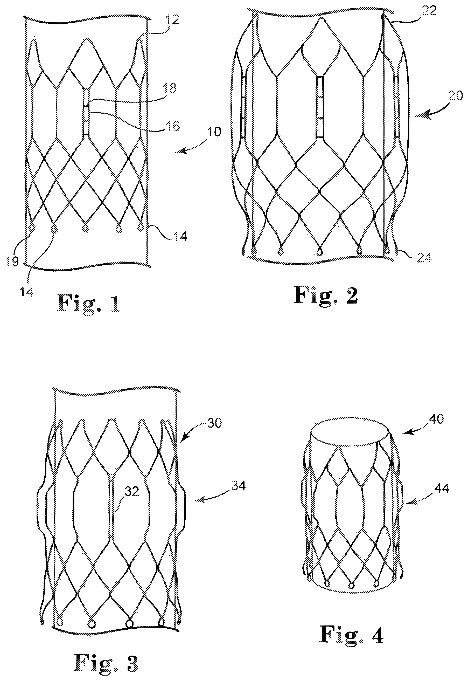
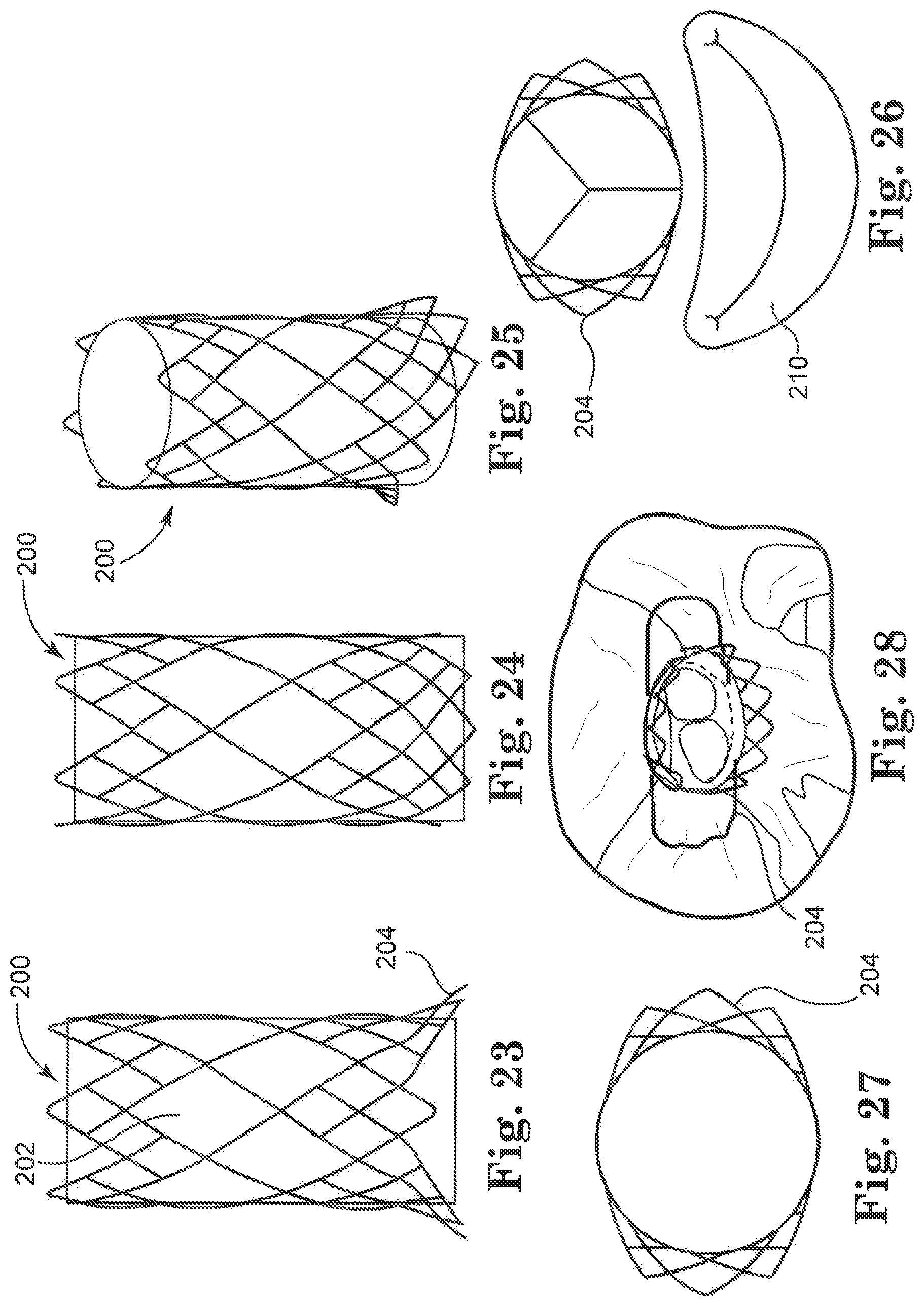
FIG. 1 is a front view of an embodiment of a stent in accordance with the invention;
FIG. 2 is a front view of an embodiment of a stent in accordance with the invention;
FIG. 3 is a front view of an embodiment of a stent in accordance with the invention;
FIG. 4 is a perspective view of a stent embodiment in accordance with the invention;
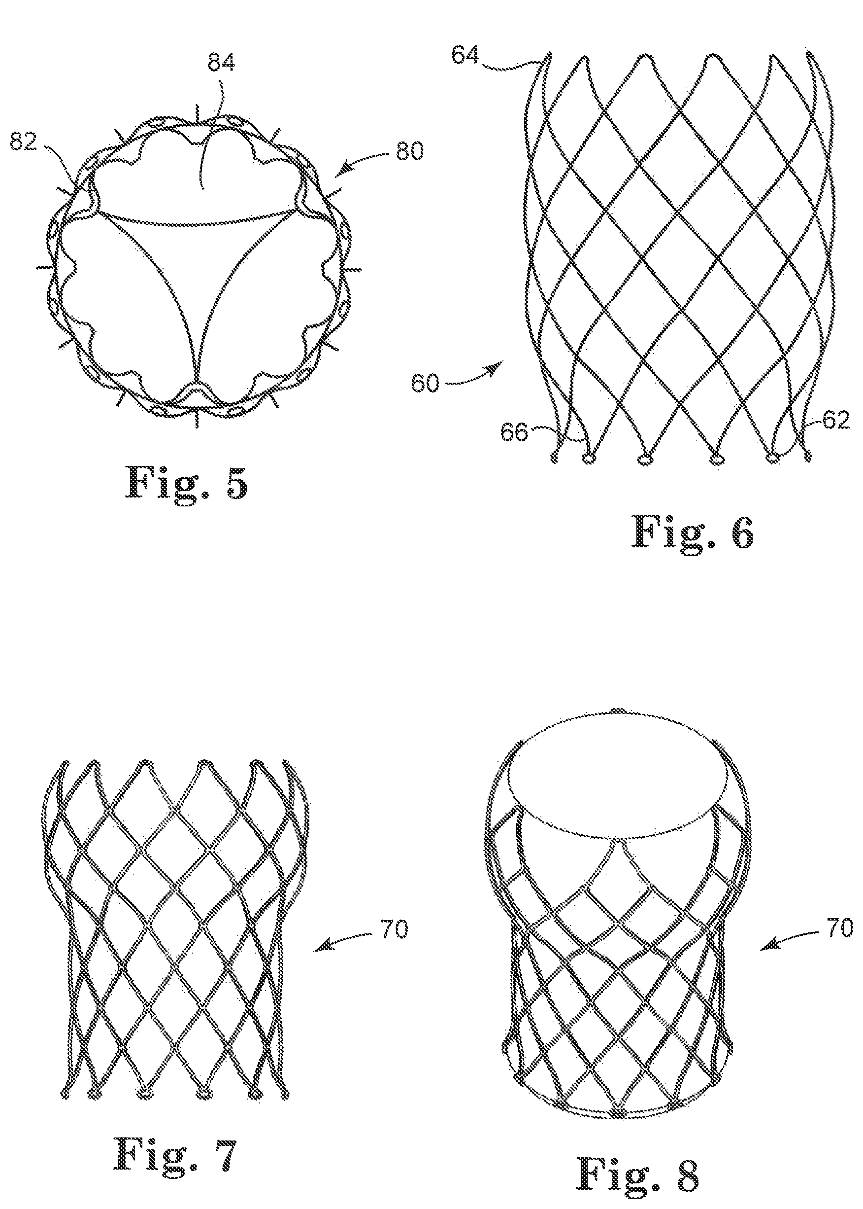
FIG. 5 is a top view of another stent embodiment;
FIG. 6 is a front view of another stent embodiment;
FIG. 7 is a front view of another stent embodiment;
FIG. 8 is a perspective view of another stent embodiment;
FIG. 9 is a perspective view of a stent embodiment having extending elements and positioned on a mandrel;
FIG. 10 is a front view of an exemplary delivery system that can be used for delivering a stent of the type illustrated in FIG. 9;
FIG. 11-13 are enlarged front views of a portion of a delivery system for delivering a stent of the type shown in FIG. 9, including three sequential delivery steps;
FIG. 14 is a front schematic view of a stent positioned in an aorta;
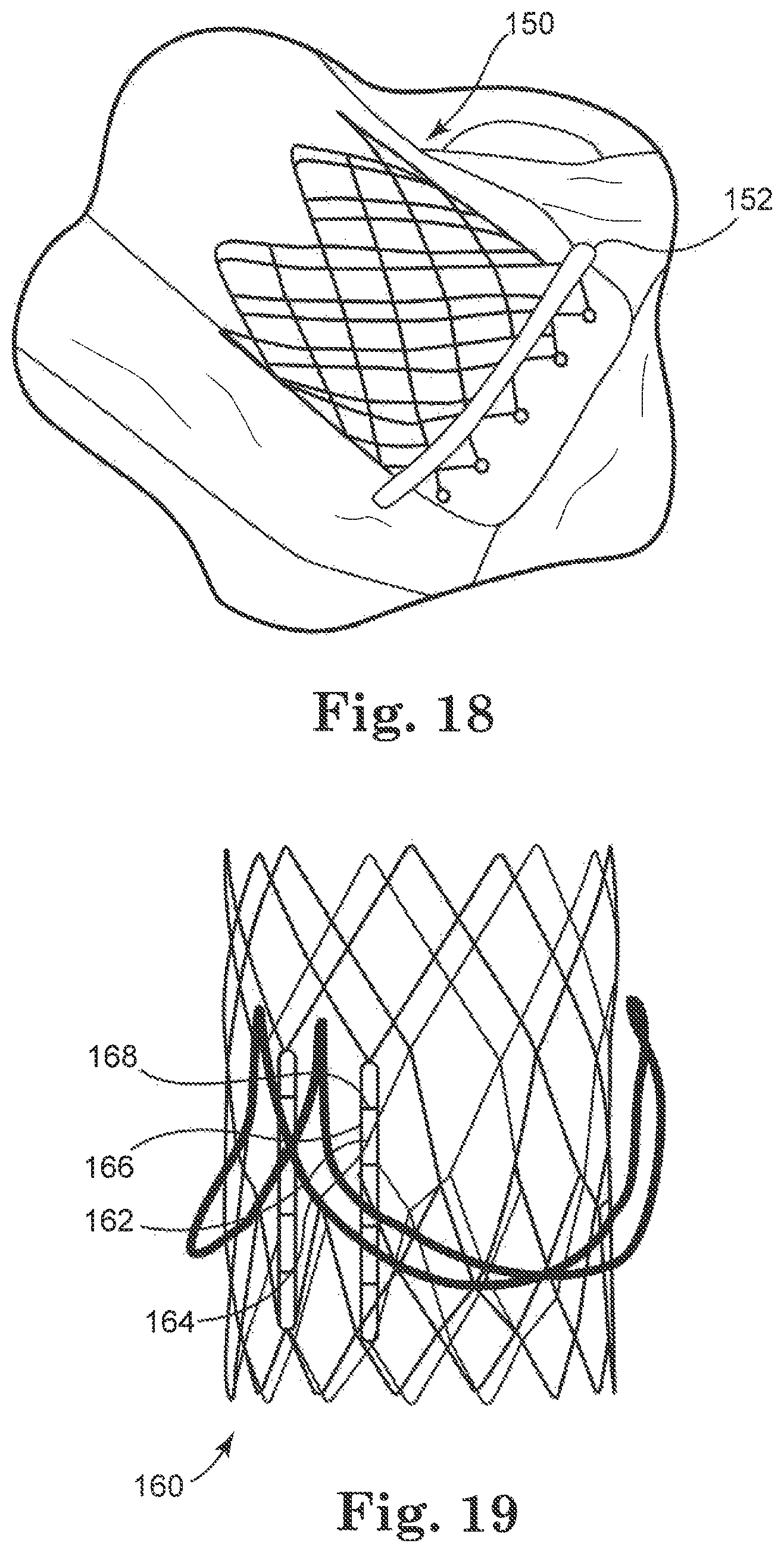
FIGS. 15-18 are perspective views of different stent embodiments, each positioned within a heart vessel;
FIG. 19 is a front view of a stent embodiment;
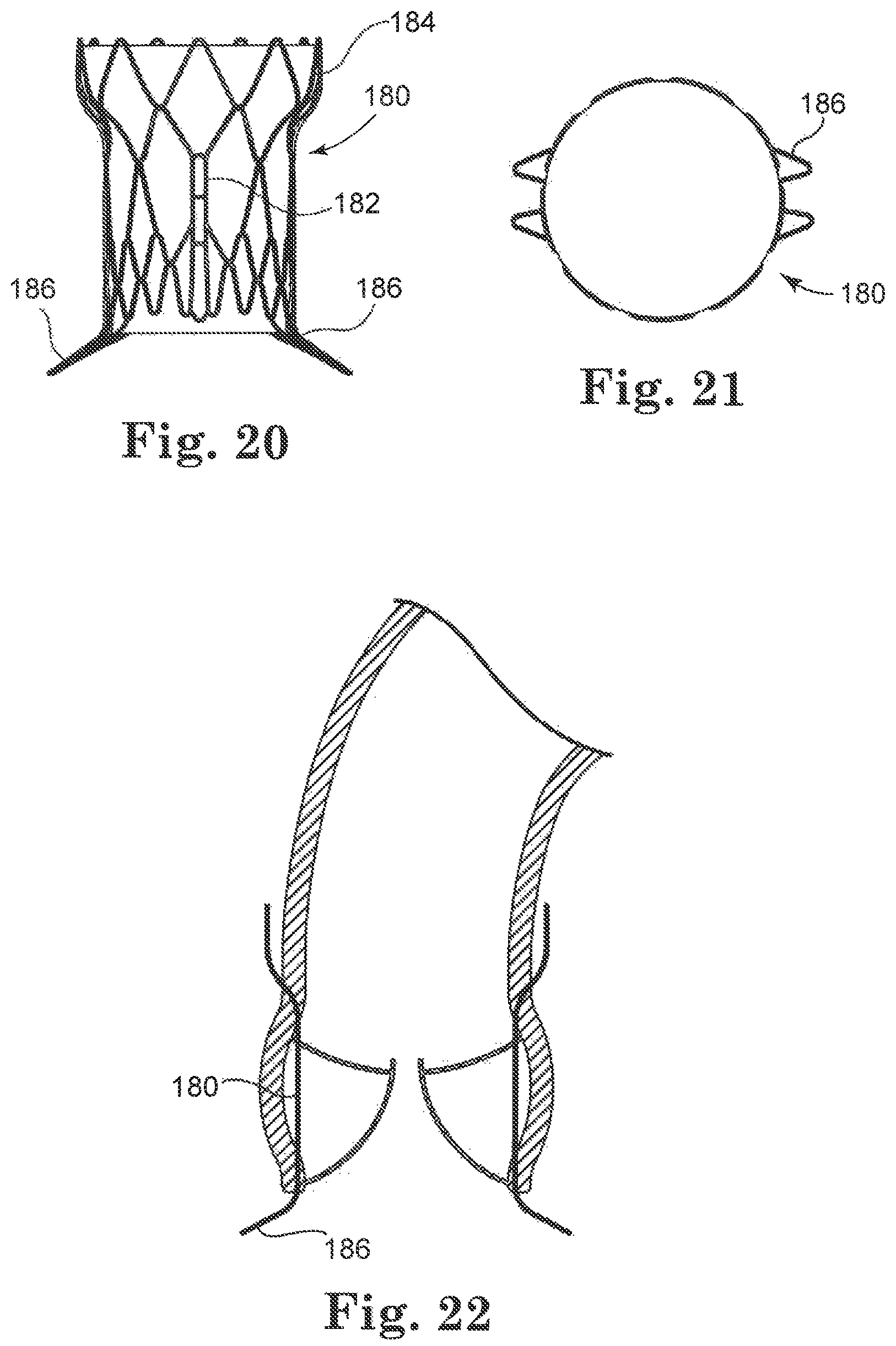
FIG. 20 is a front view of a stent embodiment;
FIG. 21 is a top view of the stent of FIG. 20;
FIG. 22 is a schematic front view of the stent of FIG. 20 positioned in a heart vessel;
FIG. 23 is a front view of another stent embodiment;
FIG. 24 is a side view of the stent of FIG. 23;
FIG. 25 is a perspective view of the stent of FIG. 23, positioned on a mandrel;
FIG. 26 is a top view of the stent of FIG. 23 positioned relative to a schematic view of a heart vessel, wherein the stent includes leaflets in its interior portion;
FIG. 27 is a top view of the stent of FIG. 23;
FIG. 28 is a perspective top view of the stent of FIG. 23 positioned in a heart;
FIG. 29 is a front view of another embodiment of a stent positioned on a mandrel;
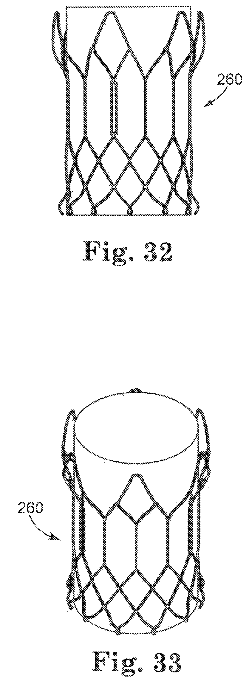
FIGS. 30 and 31 are front and perspective views respectively, of a solid model of a stent of the type illustrated in FIG. 29;
FIGS. 32 and 33 are front perspective views, respectively, of a stent embodiment;
FIGS. 34 and 35 are front views of a valved stent of the invention;
FIG. 36 is a schematic front view of a stent assembly being delivered to a heart valve;
FIG. 37 is a front view of a stent assembly positioned in a heart valve;
FIG. 38 is a front view of the stent assembly shown in FIGS. 36 and 37;
FIG. 39 is a front view of a stent assembly having a length L positioned in a heart vessel;
FIG. 40 is a top view of another stent embodiment positioned relative to a schematic view of an anatomical position in a heart;
FIG. 41 is a top view of another stent embodiment;
FIG. 42 is a top view of another stent positioned relative to the interventricular septum and the mitral apparatus;
FIGS. 43-45 are perspective views of additional stent embodiments;
FIG. 46 is a front view of another stent embodiment;
FIGS. 47-50 are front schematic views of embodiments of stents positioned in a heart vessel;
FIGS. 51-53 are front views of a different stents positioned relative to a portion of a heart valve that is cut-away for clarity; and
FIG. 54 is a top cross-sectional view of a valve attached within a stent frame.
DETAILED DESCRIPTION
As referred to herein, the prosthetic heart valves used in accordance with various devices and methods of heart valve delivery may include a wide variety of different configurations, such as a prosthetic heart valve having tissue leaflets or a synthetic heart valve having polymeric, metallic, or tissue-engineered leaflets, and can be specifically configured for replacing any heart valve. That is, while much of the description herein refers to replacement of aortic valves, the prosthetic heart valves of the invention can also generally be used for replacement of native mitral, pulmonic, or tricuspid valves, for use as a venous valve, or to replace a failed bioprosthesis, such as in the area of an aortic valve or mitral valve, for example.
Although each of the valves used with the delivery devices and methods described herein would typically include leaflets attached within an interior area of a stent, the leaflets are not shown in many of the illustrated embodiments for clarity purposes. In general, the stents described herein include a support structure comprising a number of strut or wire portions arranged relative to each other to provide a desired compressibility, strength, and leaflet attachment zone(s) to the heart valve. Other details on particular configurations of the stents of the invention are also described below; however, in general terms, stents of the invention are generally tubular support structures, and leaflets will be secured to the support structure to provide a valved stent. The leaflets can be formed from a variety of materials, such as autologous tissue, xenograph material, or synthetics as are known in the art. The leaflets may be provided as a homogenous, biological valve structure, such as a porcine, bovine, or equine valve. Alternatively, the leaflets can be provided independent of one another (e.g., bovine or equine pericardial leaflets) and subsequently assembled to the support structure of the stent. In another alternative, the stent and leaflets can be fabricated at the same time, such as may be accomplished using high strength nano-manufactured NiTi films of the type produced at Advanced Bio Prosthetic Surfaces Ltd. (ABPS) of San Antonio, Tex., for example. The support structures are generally configured to accommodate three leaflets; however, the replacement prosthetic heart valves of the invention can incorporate more or less than three leaflets.
In more general terms, the combination of a support structure with one or more leaflets can assume a variety of other configurations that differ from those shown and described, including any known prosthetic heart valve design. In certain embodiments of the invention, the support structure with leaflets utilize certain features of known expandable prosthetic heart valve configurations, whether balloon expandable, self-expanding, or unfurling (as described, for example, in U.S. Pat. Nos. 3,671,979; 4,056,854; 4,994,077; 5,332,402; 5,370,685; 5,397,351; 5,554,185; 5,855,601; and 6,168,614; U.S. Patent Application Publication No. 2004/0034411; Bonhoeffer P., et al., "Percutaneous Insertion of the Pulmonary Valve", Pediatric Cardiology, 2002; 39:1664-1669; Andersou H R, et al., "Transluminal Implantation of Artificial Heart Valves", EUR Heart J., 1992; 13:704-708; Anderson, J. R., et al., "Transluminal Catheter Implantation of New Expandable Artificial Cardiac Valve", EUR Heart J., 1990, 11: (Suppl) 224a; Hilbert S. L, "Evaluation of Explanted Polyurethane Trileaflet Cardiac Valve Prosthesis", J Thorac Cardiovascular Surgery, 1989; 94:419-29; Block P C, "Clinical and Hemodynamic Follow-Up After Percutaneous Aortic Valvuloplasty in the Elderly", The American Journal of Cardiology, Vol. 62, Oct. 1, 1998; Boudjemlinc, Y., "Steps Toward Percutaneous Aortic Valve Replacement", Circulation, 2002; 105:775-558; Bonhoeffer, P., "Transcatheter Implantation of a Bovine Valve in Pulmonary Position, a Lamb Study", Circulation, 2000:102:813-816; Boudjemline, Y., "Percutaneous Implantation of a Valve in the Descending Aorta In Lambs", EUR Heart J, 2002; 23:1045-1049; Kulkinski, D., "Future Horizons in Surgical Aortic Valve Replacement: Lessons Learned During the Early Stages of Developing a Transluminal Implantation Technique", ASAIO J, 2004; 50:364-68; the teachings of which are all incorporated herein by reference).
Orientation and positioning of the stents of the invention may be accomplished either by self-orientation of the stents (such as by interference between features of the stent and a previously implanted stent or valve structure) or by manual orientation of the stent to align its features with anatomical or previous bioprosthetic features, such as can be accomplished using fluoroscopic visualization techniques, for example. For example, when aligning the stents of the invention with native anatomical structures, they should be aligned so as to not block the coronary arteries, and native mitral or tricuspid valves should be aligned relative to the anterior leaflet and/or the trigones/commissures.
Some embodiments of the support structures of the stents described herein can be a series of wires or wire segments arranged so that they are capable of transitioning from a collapsed state to an expanded state. In some embodiments, a number of individual wires comprising the support structure can be formed of a metal or other material. These wires are arranged in such a way that a support structure allows for folding or compressing to a contracted state in which its internal diameter is greatly reduced from its internal diameter in an expanded state. In its collapsed state, such a support structure with attached valves can be mounted over a delivery device, such as a balloon catheter, for example. The support structure is configured so that it can be changed to its expanded state when desired, such as by the expansion of a balloon catheter. The delivery systems used for such a stent should be provided with degrees of rotational and axial orientation capabilities in order to properly position the new stent at its desired location.
The wires of the support structure of the stents in other embodiments can alternatively be formed from a shape memory material such as a nickel titanium alloy (e.g., Nitinol) or a very high-tensile material that will expand to its original state after compression and removal of external forces. With this material, the support structure is self-expandable from a contracted state to an expanded state, such as by the application of heat, energy, and the like, or by the removal of external forces (e.g., compressive forces). This support structure can be repeatedly compressed and re-expanded without damaging the structure of the stent. In addition, the support structure of such an embodiment may be laser cut from a single piece of material or may be assembled from a number of different components. For these types of stent structures, one example of a delivery system that can be used includes a catheter with a retractable sheath that covers the stent until it is to be deployed, at which point the sheath can be retracted to allow the stent to expand. Alternatively, the stent structures of the invention can be implanted using conventional surgical techniques and/or minimally invasive surgical procedures. In such cases, the stents of the invention can advantageously require relatively few or no sutures to secure the stent to an anatomical location within the patient.
Referring now to the Figures, wherein the components are labeled with like numerals throughout the several Figures, and initially to FIGS. 1-5 illustrate stents 10, 20, 30, and 40, respectively, each of which is positioned over a mandrel With particular reference to FIG. 1, stent 10 includes a first end 12 having six crowns and a second end 14 having twelve crowns. Each of the stent crowns at the second end 14 includes a loop or eyelet 19 that can be used for attachment to a delivery system and/or tissue valve, for example. It is contemplated that each of the crowns at the second end includes a loop or eyelet 19, as shown, or that only some of the crowns include such a loop or eyelet. The size and shape of the loops 19 can all be the same on a single stent, or they can have different sizes and/or shapes. Stent 10 further includes at least one longitudinal post 16, which can be used for attachment of tissue to the stent, along with providing additional stability to the first end 12 of the stent. The longitudinal post 16 extends generally along the annular region of the stent 10 and has a height that accommodates attachment of leaflet material. That is, the height of the post 16 is generally the same as the desired commissural height for the stent 10. As shown, the longitudinal posts 16 are comprised of two bars or vertical portions that are spaced from each other by a sufficient distance to allow leaflets to be drawn between the vertical portions at the leaflet commissures. Other skirt material portions and/or commissure protection features can also be drawn through the space between the vertical portions. The space between the vertical portions of each post 16 may have incremental steps 18, as shown in FIG. 1, which help to provide anchoring points for suturing, for example, or the posts may not include such steps, as shown with post 132 in FIG. 3, which will be discussed in further detail below. If steps 18 are provided, they can be generally perpendicular to the vertical posts, which will make the openings generally rectangular in shape, or the steps can be differently oriented and shaped so that the openings are circular, elliptical, or another chosen shape. It is further noted that the vertical portions of the posts 16 can be made of a different material or have a different thickness than the rest of the stent wires and/or the posts can be made with reinforced attachment stents or welds on the outflow and to provide additional strength in this area.
With this stent 10, wire structure extends between one end of the post 16 and the first end 12 (which may be referred to as the aortic aspect of the stent) and additional wire structure extends between the other end of the stent post and the second end 14 (which may be referred to as the ventricular aspect of the stent). The stent 10 may include one longitudinal post 16 for each commissure of the valve that will be attached thereto, if desired. That is, for a three-leaflet valve, three longitudinal posts 16 will be provided.
The stent 20 of FIG. 2 includes multiple wires that are arranged in a generally similar configuration to that discussed above relative to FIG. 1. However, stent 20 further includes a central bulbous region between its first and second ends 22, 24 that is larger in diameter than the diameters of the first and second ends of the stent. The bulbous region can be configured to generally match the contours of the anatomy where the stent will be positioned in the patient (e.g., at the aortic valve sinus region). The first end 22 is flared inwardly (i.e., toward the central axis of the stent), preferably by an amount that is enough to be atraumatic, but not so pronounced that it loses contact with the patient's anatomy or interferes with another device (e.g., a coronary catheter) at a later date. Thus, the inward flare can be less than that shown, although it is possible that the flare is even greater than that shown. In addition, the second end 24 is slightly flared outwardly, as shown in the Figure. This flare at the second end 24 of the stent 20 (i.e., away from the central longitudinal axis of the stent) can prevent or minimize leakage between the implanted heart valve and the native annulus and/or to provide a physical and/or visual docking feature to secure the stent against a wall of a vessel or opening in the heart to prevent migration of the stent, for example. Additionally, the second end 24 can also have an at least slightly inward bend (see FIG. 3, for example) that may be advantageous when implanting this stent in the aortic region in order to minimize trauma to adjacent anatomical structures (e.g., the mitral valve anterior leaflet or the left ventricular wall). This slight inward bend can also help to minimize pressure on the septum in the area of the bundle branch, which can in turn reduce the potential for arrythmias or heart block during or after the transcatheter valve replacement procedure.
FIGS. 3 and 4 illustrate stents 30 and 40 that are "selectively" flared to match particular desired shapes for portions of the stent. For example, certain stent wires are flared outwardly to avoid potential interference between the stent and the tissue leaflets of the replacement valves. The stent features to which the tissue will be attached may not be flared at all, such that the stent is relatively tubular, or these wires could instead be flared inwardly or outwardly. Stents 30, 40 include central regions 34, 44, respectively that are somewhat larger in diameter than the adjacent portions of the stent. The stent 30 further includes at least one longitudinal element or feature that can be used for attachment of tissue to the stent, such as a longitudinal post 32. Such posts 32 can also be positioned at the same distance from the longitudinal axis as the other stent elements in the central region 34, or the longitudinal posts can be closer to or further from the central axis of the stent than the other stent elements in the central region 34, if desired. By positioning the posts closer to the central axis than the other wires in the central region 34, the free edges of the dynamic leaflets positioned inside the stent 30, 40 of the new or replacement valve would be less likely to contact the stent posts when the valve leaflets are fully open. This reduced contact can reduce the potential for wear on the leaflets during valve cycling. An additional benefit of positioning the wires of the post closer to the central longitudinal axis as the other stent wires is to minimize stress at the commissures, and to help maintain coronary perfusion. This can be accomplished by limiting the opening of the leaflet so that coronary flow behind the valve leaflets is maintained. Yet another benefit of these configurations having attachment points that are inwardly offset from the largest outer diameter of the stent is that a smaller tissue valve can be used, which in turn reduces the overall transcatheter crimp profile of the delivery system.
Reduction of the potential wear on the valve leaflets can alternatively be accomplished by fastening leaflet commissures closer to the center of the stent than to the outer circumference. FIG. 54 illustrates such an arrangement with a schematic view of an outer stent frame 400 having three leaflets 402 arranged so that each two adjacent leaflets are attached to the stent frame 400 at a leaflet commissure area 404. Another fastening point of each of these sets of leaflets 402 at the commissure area 404 is shifted inwardly toward the center of the stent frame 400 to an inner fastening point 406. In this way, when the leaflets 402 are open, their free edges can only move out as far as the circle or inner area 408, which is shown schematically with a broken line. As shown, even if the leaflets 402 are in this fully open position, they will not contact the outer stent frame 400, thereby reducing potential wear on the valve leaflets.
Stents 10, 20, and 40 each include an arrangement of wires that provides twelve stent crowns at one end and six stent crowns at the opposite end, while stent 30 includes twelve crowns at both ends. For embodiments that include twelve crowns at the inflow end of the stent, this configuration can provide additional strength to the stent annulus area to prevent migration, to open stenotic native valve orifices, and also to provide a greater number of points for attaching pericardial leaflets to the stent. It is possible, however, to provide less than twelve (e.g., six) crowns at the outflow because the same stent strength is not required at this end for less tissue attachment points are needed. These illustrated stents are only some of the arrangements of wires that can achieve this feature of having different numbers of stent crowns at opposite ends of a single stent. In a further alternative, each of the ends of one stent can have the same number of stent crowns, but the center portion can have a more or less dense concentration of wires than either of the ends. In any case, a stent having less stent crowns at one of its ends may simplify the use of an associated delivery system, since the end with less stent crowns will have a corresponding smaller number of crowns that need to be connected to the delivery system.
FIGS. 5-8 illustrate additional stent embodiments 80, 60, 70. Stent 60 has a similar shape to the stent 20 of FIG. 2; however, stent 60 includes the same number of stent crowns at both ends, and also does not have the same longitudinal posts that are part of the wire arrangement of stent 20. Rather, stent 60 includes a generally regular diagonal criss-cross wire pattern along its entire length, and further includes multiple eyelets or hooks 62 at once end. A first stent end 64 is flared generally inwardly and a second stent end 66 is contoured both inwardly and outwardly as compared to the central region of the stent. Stent 70 includes a bulbous shape to the wires at one end, eyelets or hoops at the opposite end, and differing numbers of stent crowns at the opposite ends of the stent. Stent 80 includes pocket portions 82 that provide attachment points for the leaflets 84 that are positioned inwardly from the outer diameter of the stent 80. Again, these inwardly located attachment points will reduce the potential for leaflet abrasion and moves the commissure attachment points to an area that that puts less stress on the leaflets. Finally, the pockets 82 provide an area where the suture knots can be positioned so that they do not increase the overall crimp profile of the valve.
FIG. 9 illustrates another stent embodiment 90 that includes several features described above relative to stent crowns, longitudinal posts, incremental steps on at least one of the posts and the wire. Stent 90 also includes at least one longitudinal stent post 92 comprised of two vertical bars spaced from each other. Stent 90 further includes three wings 94, each of which extends outwardly from the stent body and between two longitudinal posts 92. The longitudinal posts 92 can be positioned inwardly of the outer diameter of the stent 90 to provide the advantages discussed above relative to avoiding leaflet abrasion and the like. These wings can be used to dock the stent against the top aspect of the native leaflets when the stent is implanted. Again, this stent has differing numbers of crowns at its opposite ends, and hooks or eyelets on the crowns at one end.
FIGS. 10-13 illustrate a portion of one exemplary delivery system 100 for delivering a stent having wings, such as stent 90. In particular, FIG. 10 shows a delivery system tip including a fully crimped stent enclosed within a main catheter sheath. FIG. 1 shows the wings 94 being deployed from the delivery system 100 by retracting the main catheter sheath 102. In an implantation, the wings 94 can be positioned to interface with the outflow aspect of the native valve leaflets. Once these wings 94 are in contact with the native valve leaflets, the inflow or annular end of the stent is deployed by driving the catheter tip forward, as illustrated in FIG. 12. The native leaflets will now contact the wings 94 and inflow end of the stent 90, thereby minimizing the potential for migration of the replacement valve. The outflow end of the stent can now be deployed, as shown in FIG. 13, to fully re-expand the stent 90 release it from the delivery system, which is accomplished by further retracting the main catheter sheath.
FIG. 14 illustrates a stent 110 that includes a highly flexible delivery system attachment end 112 that enables the portion of the stent 110 that interfaces with the anatomy to create secure fixation to be fully deployed while still attached to the delivery system. This system enables a sprocket-style delivery system attachment mechanism that can help to minimize the delivery system diameter size. A sprocket-style delivery system includes some type of inner core member from which multiple protrusions extend, where the shape of the protrusions allow for engagement with wires of a stent. Stent 110 does not require attachment of each crown on the aortic end of the stent, while still enabling the ventricular region of the stent to fully deploy to assess functionality and positioning, which can thereby allow for a smaller diameter for the delivery system. As shown, stent 110 is positioned relative to an aorta 114, and stent 110 includes an outflow end that has very flexible struts that enable the anchoring portion of the stent to be fully deployed to assess the valve functionality and positioning, while still being captured on a sprocket-style delivery system. The outer diameter of the stent can preferably expand to match the maximum inner diameter of the anchoring region.
FIG. 15 illustrates another embodiment of a stent 120 having a central region 122 with a diameter that is larger than the diameter at either of the ends. A first end 124 has six stent crowns, while the opposite second end 126 has twelve stent crowns, each of which includes an eyelet 128. With such an arrangement, the number of crowns provided at the outflow end of the stent is reduced, thereby requiring fewer points for attachment to a delivery system. FIG. 16 illustrates another stent embodiment 130 including flared regions at both ends and a central region that is generally cylindrical.
FIG. 17 illustrates another embodiment of a stent 140 that is positioned at the aortic valve position of a heart. Start 140 includes six stet crowns at one end and twelve stent crowns at the opposite and, and further includes a central area with a relatively large opening or gap 142 between the wires. The gap 142 can be positioned at the coronary ostia so as to not obstruct or interfere with blood flow. The stents 120, 130, 140, along with many of the other stent embodiments described herein, are designed to match with native anatomic features of a patient to improve resistance to migration and improve paravalvular replacement valve sealing.
FIG. 18 illustrates another embodiment of a stent 150 that is designed for anatomic compatibility and includes a bulbous portion that is positioned to sit generally at the annular area of a vessel. A ring 152 shown in this figure is a sealing gasket on the outside of the stent and is positioned generally at the annulus of a vessel when implanted. The gasket can be made of fabric or inflatable tube structures, for example.
FIG. 19 illustrates a stent 160 that does not include many of the contours described relative to other stet embodiments of the invention, but includes longitudinal posts 162 for attachment of the valve tissue. Posts 162 are comprised of two longitudinal wire portions 166 spaced from each other, and further include optional intermediate members 168 that extend between the longitudinal portions 166. The outer structure ring structure shown in this drawing is provided as an illustration of the general stitching path that can be used for tissue material within the stent.
FIGS. 20-22 illustrate an embodiment of a stent 180 that includes a number of features described above for the stents of the invention, along with additional features. In particular, FIG. 20 shows the stent 180 with longitudinal posts 182 extending in the direction of the length of the stent 180, and a region 184 at one end that is bulbous or has a larger diameter than the central portion of the stent. The opposite end of the stent 180 includes flared portions 186 that extend from opposite sides of the generally tubular central portion. As shown in FIG. 21, each flared portion 186 can include two crowns, although it is possible that the flared portion 186 can be configured somewhat differently than shown (e.g., there can be more or less crowns, the crowns can be shaped differently, the flared portion 186 can extend around a larger or smaller portion of the circumference of the stent, and the like). As is further illustrated in FIG. 20, the geometry of the stent can be designed to incorporate optimal attachment points for tissue. That is, the stent node trajectory can be specifically selected to provide the desired points for the attachment of tissue. Such a feature can be considered and designed for tents including longitudinal posts, as shown in FIG. 20, and may also be considered for stents comprising more diamond-shaped wire patterns without longitudinal posts.
The outer profile of stent 180 is shown in an exemplary position within the anatomy (i.e., aorta) of a patient in FIG. 22, with the central area that includes the commissural posts being positioned in the bulbous area of an aorta. The flares 186 extend into the ventricle in order to help anchor the stent 180 in place. The flares 186 are preferably positioned in locations where they do not disrupt the native anatomical function. That is, the flares 186 should not interfere with the mitral valve anterior leaflet and should not apply pressure to the septum in the area of the conduction system bundle branch. Again, it is also preferable that the central portion of the stent 180 does not contact the native aortic sinus region, in order to minimize the potential for coronary occlusion or obstruction.
It is noted that in many of the stent embodiments shown and described herein, the aspect ratio of certain portions of the stent is exemplary, and can be somewhat different from that shown. It is further noted that if the stent of any of the embodiments is to be positioned to replace the aortic valve, the stent can be provided with a lower density wire portion in the area where the coronaries are located. To eliminate the need to clock the device, reduced wire density around the entire perimeter of the stent in the central area can be provided. Further, stent embodiments described herein may be modified to include additional structure for attachment of tissue for the valve, such as the vertical stent posts described in many of the embodiments.
FIGS. 23-28 illustrate another embodiment of a stent 200 that includes a central cylindrical portion with at least two regions with a lower density of wires, each of which is provided for positioning in the area of the coronary openings. The wires of this lower density area are arranged to provide openings 202 that are larger than the spaces between other wires of the stent. These openings are offset along the length of the stent to be arranged in a zigzag type of pattern around the circumference of the stent 120. One end of the stent 200 includes flared portions 204 that extend from opposite sides of the central cylindrical portion of the stent. Each flared portion 204 includes three crowns, although variations of this configuration are contemplated, as discussed above relative to flared stent portions. As shown in FIG. 26, stent 200 is positioned relative to a mitral valve 210 so that one of the flared portions is positioned at the left ventricle, and one of the openings in the stent is positioned at the left coronary artery. FIG. 27 is a top view of the stent 190, and FIG. 28 shows one exemplary position of the stent 190 relative to the anatomy of a patient, including the septum and anterior leaflet of the mitral valve.
FIG. 29 illustrates a stent 220 that includes openings 222 (i.e., areas of lower wire density) for the coronaries, and further includes sub-annular and supra-annular circumferential wings to help secure the stent to the patient's native anatomy. In particular, the area below the openings 222 includes an outward curve or flare to create a wing 224 that can extend around all or part of the circumference of the stent 220. The wires then curve back toward the central longitudinal axis of the stent, then curve or flare outwardly again to create a wing 226 that can extend around all or a part of the circumference of the stent 220. As shown, the wings 224, 226 and the area between them form a generally sinusoidal configuration, where the wing 224 can be positioned above an annulus and wing 226 can be positioned below that annulus to provide the anchoring for a more secure attachment in that position. This series of wings can help to anchor the stent in regions of calcified or fused leaflets in the aortic stenosis patient population. Stent 220 further includes imaging markers 228 that can be used to identify the high and low points of the commissures, the annular (valve) plane of the implant, and/or other features. Markers can also be used to identify high and low boundaries for optimal implant placement within the patient's anatomy.
FIGS. 30 and 31 are solid models of a stent 240 that is configured similarly to the stent of FIG. 29, including the sinusoidal shape at one end that creates wing areas. These wings can have a different profile from that shown, although it is preferable in this embodiment that there are sinusoidal "peaks" 242, 244 that are separated by a "valley" 246, where the annulus of a valve can be positioned in the valley 246 so that the peaks 242, 244 are on opposite sides of the annulus. The peaks and valleys can have different heights than shown, and the spacing between the peaks may also be different. That is, the spacing between the sub-annular and supra-annular flares can be varied, depending on the specific procedure that will be performed and the desired characteristics of the stent. These embodiments, along with other shaped stents described herein, can help to minimize stent migration within the patient due to the ability of the stent to conform to various contours of the patient's anatomy. FIG. 30 also illustrates an optional groove 248 that can be positioned generally around the periphery of the stent 240 to match the native 3-dimensional configuration of the native anatomy. A gasket 250 can be positioned within the groove 248, where such a gasket 250 can include one continuous structure that generally follows the shape of the groove 248, or it can include one or more pieces within portions of the groove 248. The gasket 250 can improve paravalvular sealing. Further, the gasket 250 can be made of a material that can heal into the native tissue of the patient, which can help the stent to resist migration.
FIGS. 32 and 33 illustrate another stent embodiment 240 that includes flares at both the sub-annular and sinotubular junction (STJ) areas. The illustrated stent further includes vertical stent posts, twelve inflow crowns and six outflow crowns although there could be more or less than these numbers of inflow and outflow crowns. Stent 240 has a wire arrangement similar to that shown for the stents of FIGS. 1-4 and other stents described and shown herein; however, the central area of stent 240 is more tubular or "straight," with slightly curved areas at both ends.
One exemplary stent of the invention combines the following features: eyelets at one end for attachment to the delivery system and tissue valve; vertical commissural tissue attach struts or posts; moderately flared non-commissural attach vertical struts or STJ flare; sub-annular flares; inflow and outflow atraumatic curvatures; a twelve crown inflow; and six tapered crowns at the outflow end. Such an embodiment of a stent is illustrated, for example, as stent 250 in FIGS. 34 and 35. Stent 250 further includes tissue material 252 attached within its internal area to provide leaflets for the valve. Two spaced-apart vertical members are used to make up vertical posts 254, one of which is most visible in FIG. 35. One exemplary pattern for stitching the tissue to the vertical post 254 is also illustrated, although the stitching pattern can differ from that shown.
Delivering any balloon-expandable stents of the invention to the implantation location can be performed percutaneously. In general terms, this includes providing a transcatheter assembly, including a delivery catheter, a balloon catheter, and a guide wire. Some delivery catheters of this type are known in the art, and define a lumen within which the balloon catheter is received. The balloon catheter, in turn, defines a lumen within which the guide wire is slideably disposed. Further, the balloon catheter includes a balloon that is fluidly connected to an inflation source. It is noted that if the stent being implanted is the self-expanding type of stent, the balloon would not be needed and a sheath or other restraining means would be used for maintaining the stent in its compressed state until deployment of the stent, as described herein. In any case, for a balloon-expandable stent, the transcatheter assembly is appropriately sized for a desired percutaneous approach to the implantation location. For example, the transcatheter assembly can be sized for delivery to the heart valve via an opening at a carotid artery, a jugular vein, a sub-clavian vein, femoral artery or vein, or the like. Essentially, any percutaneous intercostals penetration can be made to facilitate use of the transcatheter assembly.
Prior to delivery, the stent is mounted over the balloon in a contracted state to be as small as possible without causing permanent deformation of the stent structure. As compared to the expanded state, the support structure is compressed onto itself and the balloon, thus defining a decreased inner diameter as compared to an inner diameter in the expanded state. While this description is related to the delivery of a balloon-expandable stent, the same basic procedures can also be applicable to a self-expanding stent, where the delivery system would not include a balloon, but would preferably include a sheath or some other type of configuration for maintaining the stent in a compressed condition until its deployment.
With the stent mounted to the balloon, the transcatheter assembly is delivered through a percutaneous opening (not shown) in the patient via the delivery catheter. The implantation location is located by inserting the guide wire into the patient, which guide wire extends from a distal end of the delivery catheter, with the balloon catheter otherwise retracted within the delivery catheter. The balloon catheter is then advanced distally from the delivery catheter along the guide wire, with the balloon and stent positioned relative to the implantation location. In an alternative embodiment, the stent is delivered to an implantation location via a minimally invasive surgical incision (i.e., non-percutaneously). In another alternative embodiment, the stent is delivered via open heart/chest surgery. In one embodiment of the stents of the invention, the stent includes a radiopaque, echogenic, or MRI visible material to facilitate visual confirmation of proper placement of the stent. Alternatively, other known surgical visual aids can be incorporated into the stent. The techniques described relative to placement of the stent within the heart can be used both to monitor and correct the placement of the stent in a longitudinal direction relative to the length of the anatomical structure in which it is positioned.
Once the stent is properly positioned, the balloon catheter is operated to inflate the balloon, thus transitioning the stent to an expanded state. Alternatively, where the support structure is formed of a shape memory material, the stent can self-expand to its expanded state.
One or more markers on the valve, along with a corresponding imaging system (e.g., echo, MRI, etc.) can be used with the various repositionable delivery systems described herein in order to verify the proper placement of the valve prior to releasing it from the delivery system. A number of factors can be considered, alone or in combination, to verify that the valve is properly placed in an implantation site, where some exemplary factors are as follows: (1) lack of paravalvular leakage around the replacement valve, which can be advantageously examined while blood is flowing through the valve since these delivery systems allow for flow through and around the valve; (2) optimal rotational orientation of the replacement valve relative to the coronary arteries; (3) the presence of coronary flow with the replacement valve in place; (4) correct longitudinal alignment of the replacement valve annulus with respect to the native patient anatomy; (5) verification that the position of the sinus region of the replacement valve does not interfere with native coronary flow; (6) verification that the sealing skirt is aligned with anatomical features to minimize paravalvular leakage; (7) verification that the replacement valve does not induce arrhythmias prior to final release; and (8) verification that the replacement valve does not interfere with function of an adjacent valve, such as the mitral valve.
FIGS. 36-39 are schematic views of various embodiments of stents of the present invention. In particular, FIG. 36 illustrates a stent assembly 280 that includes features that align and secure it with specific anatomical features in the left ventricle region and the left ventricular outflow tract region of a patient. Stent assembly 280 includes a stented valve 282 from which tethers 284 extend. Tethers 284 are preferably flexible to accommodate curvature of the native aorta above the valve annulus. Optional anchors 286 are shown at the distal ends of the stent. More specifically, each of the tethers 284 extends from one of the commissures 288 of the stent 282. The stent assembly 280 farther includes a distal element such as a stent graft 290 positioned between the tethers 284 near the anchors 286, which is flexible and can accommodate widely varying patient anatomy. The stent graft 290 will be positioned distal to the sinus area of the left ventricular outflow tract when implanted. This configuration can facilitate stabilization of the stent assembly and may be designed to register or interface with another stent graft that is implanted at a later time.
This stent assembly 280 can include flexible connections between annular and supra-annular stent aspects. The flexible connections may be elastomeric, fabric, metal, or the like. Such flexible connections can help the stent assembly to accommodate most varying anatomy above the sinotubular junction and also to accommodate aortic curvature. In addition, the flexible connections can make the stent assembly able to accommodate anerysmal aortas.
The stent assembly 280 may further include a gasket 294 positioned adjacent an end of the stented valve 282. In addition, when the stent assembly is implanted in a patient, a plaque pocket 296 can be created that provides embolic protection by creating a volume that can entrap plaque, calcification, and other emboli from traveling in a distal direction and causing a thromembolic event, such as a stroke.
Alternatively, portions of the system may be designed to include a longer useful life than others. For example, the frame of the present invention could be designed to have a relatively long useful life (e.g. 20 years), while the tissue component could have a relatively shorter useful life (e.g. 10 years).
An embolic protection device 292 can be provided distal to the stent assembly 280, as is shown in FIG. 36. The device 292 can be utilized during the implantation procedure to capture and trap any emboli released and/or generated by the valve procedure, while still maintaining uninhibited or sufficient perfusion through the aorta and coronary arteries during valve implantation. In addition, FIGS. 36-39 illustrate a portion of the stent positioned above the sinotubular junction 284 covered with fabric, polymer, and/or tissue, which can serve this same purpose.
FIGS. 37-39 illustrate alternative views of the stent assembly 280, both within a heart vessel and independent of anatomical structure (FIG. 38). It is noted that the anchoring of the stent posts via the anchors 286 can help to prevent valve ejection. FIG. 37 shows the stent assembly 280 implanted in a supra-annular position in a patient's anatomy, which can beneficially improve the orifice area by avoiding the stenotic region of the aorta. FIG. 39 shows the flexibility of the stent graft material in order to conform to the curved area of an aorta.
FIG. 40 illustrates a top view of a stent 300 having a fixation tab 302 positioned in the non-coronary sinus area 310, and with no such tabs at either the right coronary artery 314 or the left coronary artery 312. That is, fixation components of stent 300 may secure the system to non-coronary sinus and/or regions of the left ventricle adjacent to the aortic valve annulus. This may avoid obstruction of coronary blood flow and prevent unwanted interaction between the system and the septum and mitral valve anterior leaflet. Further, the fixation tab 302 does not prevent or inhibit subsequent coronary intervention, while providing the advantage of minimizing or preventing migration of the stent toward the aorta. FIG. 41 illustrates a stent having both a fixation tab 302 and flared portions 304 that help to prevent migration of the stent. FIG. 42 illustrates stent 300 having flared regions 304 as positioned relative to the interventricular septum 306 and the mitral valve apparatus 308.
FIGS. 43-45 illustrate alternative stent embodiments 360, 370, 380, each of which comprises an extending or fixation tab 364, 374, 384, respectively, along with flared portions 362, 372, 382, respectively. Tab 364 of stent 360 is configured as a bulging wire area, tab 374 of stent 370 comprises an extension that is angled in the same general direction as the wings 372, and tab 384 of stent 380 comprises an extension that is angle in generally the opposite direction from that of the wings 382. The stent 370 is illustrated in FIG. 51 with its tab 374 positioned relative to a non-coronary sinus 376, stent 380 is illustrated in FIG. 52 with its tab 384 positioned relative to a non-coronary sinus 386, and stent 360 is illustrated in FIG. 53 with its fixation tab 364 positioned relative to a non-coronary sinus 366. As shown, these tabs can help to prevent stent migration due to their interference with the patient's anatomy.
FIGS. 47 and 48 schematically illustrate the aorta of a patient. As shown, the aorta begins to curve distal to the annulus level. Many typical transcatheter valve stents are cylindrical with a relatively straight axis. Such a stent structure does not easily conform to the native anatomy, which can present a number of potential issues. First, the reduced pressure on the anatomy at the inner portion of the curvature (such as is illustrated with the an area 332 adjacent to a stent 330 in FIG. 49) can lead to improper seating, migration, and/or paravalvular leakage. Second, increased pressure on the anatomy at the outer portion of the curvature can lead to, or increase the potential for cardiac conduction system block or interference. Third, increased pressure on the anatomy at the outer portion of the curvature can lead to local erosion, irritation, and/or dissection of tissue. Fourth, the stent can be subjected to increased torsional and/or bending stresses and strains, which can affect the short-term structural integrity of the stent. Finally, lack of conformity with the curvature of the native anatomy can inhibit the ability of the clinician to accurately or consistently position the stent/valve in the desired location.
Several stents of the present invention can alleviate this non-conformity of the valve frame with the native anatomy. In one embodiment, the stent could have a predetermined curvature that matches or more closely conforms to the native anatomy, such as stent 335 in FIG. 50. In other embodiments, the stent could have flexibility (e.g., area 322 of stent 320 in FIGS. 47-48) or a hinged area (e.g., hinge 342 of stent 340 in FIG. 48) in the portion of the stent that would enable it to conform to the native curved anatomy. FIGS. 46 and 47 illustrate stent designs that incorporate flexibility in their central regions, which in turn enables improved conformity with the native anatomy. The central areas or members 322 can be fabricated from a wide variety of materials, such as metals, polymers, fabrics, and the like. The members 322 can include a number of geometries that allow flexibility to conform to the native, curved aortic anatomy. Referring again to FIG. 36, this stent assembly incorporates elements 287 that are not attached to each other except through flexible materials such as fabric, tissue, or polymeric materials that enable a high degree of conformity with the native anatomy curvature within the ascending aorta.
The present invention also optionally or alternatively includes distal emoboli protection features which may be incorporated into a delivery system for delivering a stent assembly (e.g. in the nose assembly), such as the thromboembolic filter. The protection features may provide acute protection during percutaneous valve delivery. The protection features may afford substantially uninhibited flow through coronaries during systole or diastole.
The present invention has now been described with reference to several embodiments thereof. The entire disclosure of any patent or patent application identified herein is hereby incorporated by reference. The foregoing detailed description and examples have been given for clarity of understanding only. No unnecessary limitations are to be understood therefrom. It will be apparent to those skilled in the art that many changes can be made in the embodiments described without departing from the scope of the invention. Thus, the scope of the present invention should not be limited to the structures described herein, but only by the structures described by the language of the claims and the equivalents of those structures.
* * * * *
D00000
D00001
D00002
D00003
D00004
D00005
D00006
D00007
D00008
D00009
D00010
D00011
D00012
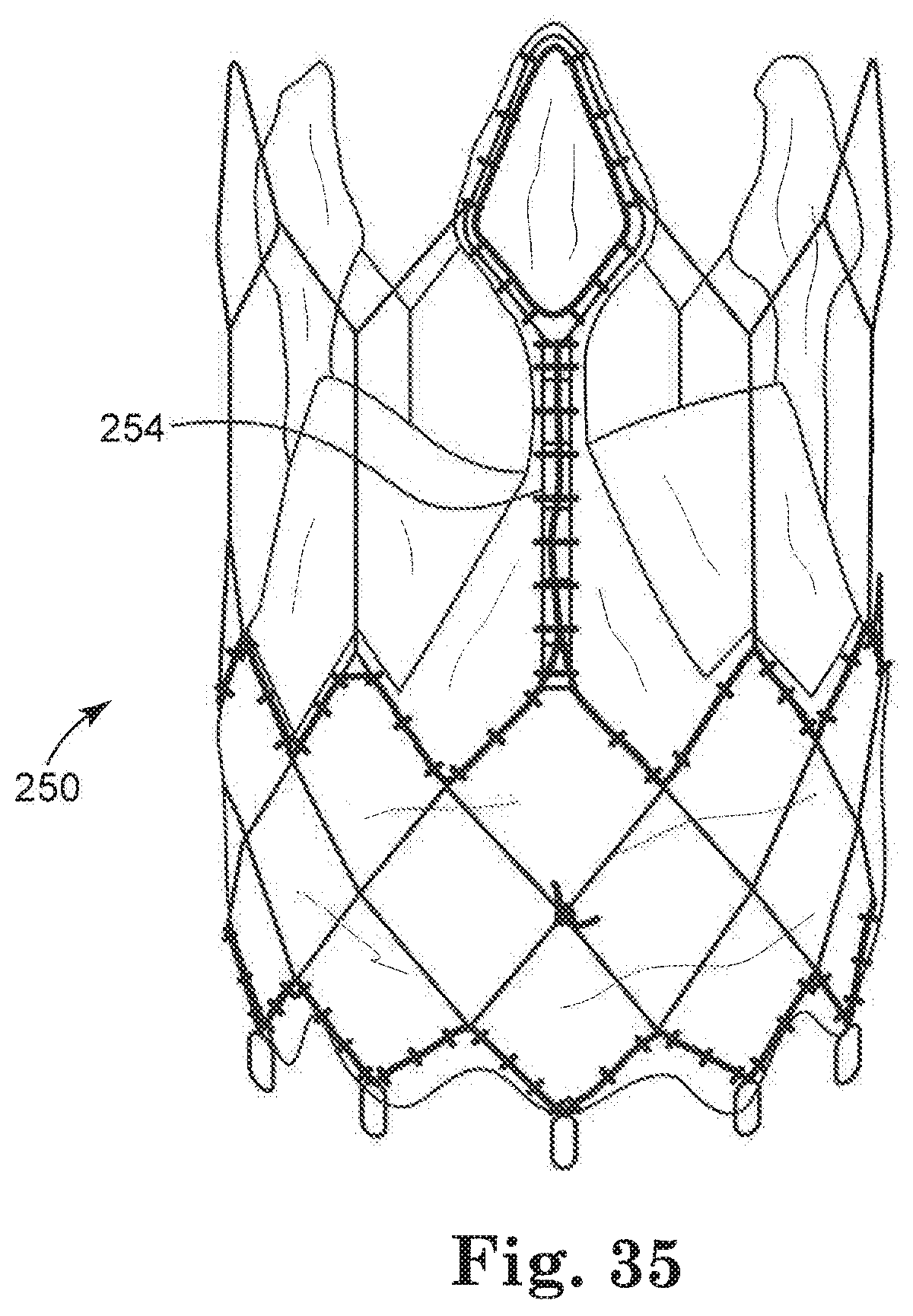
D00013
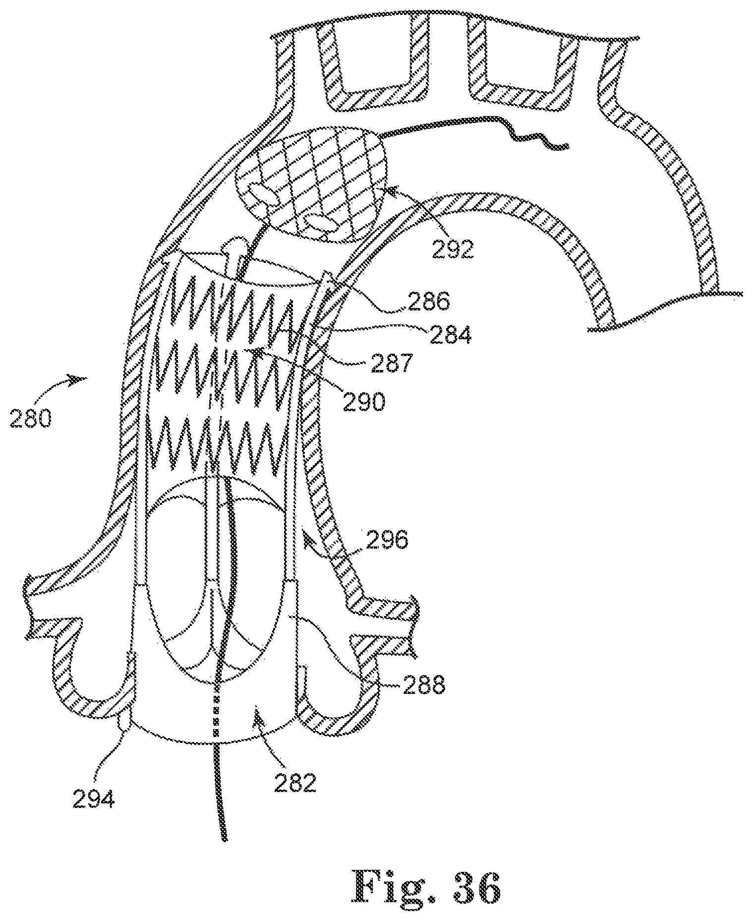
D00014

D00015
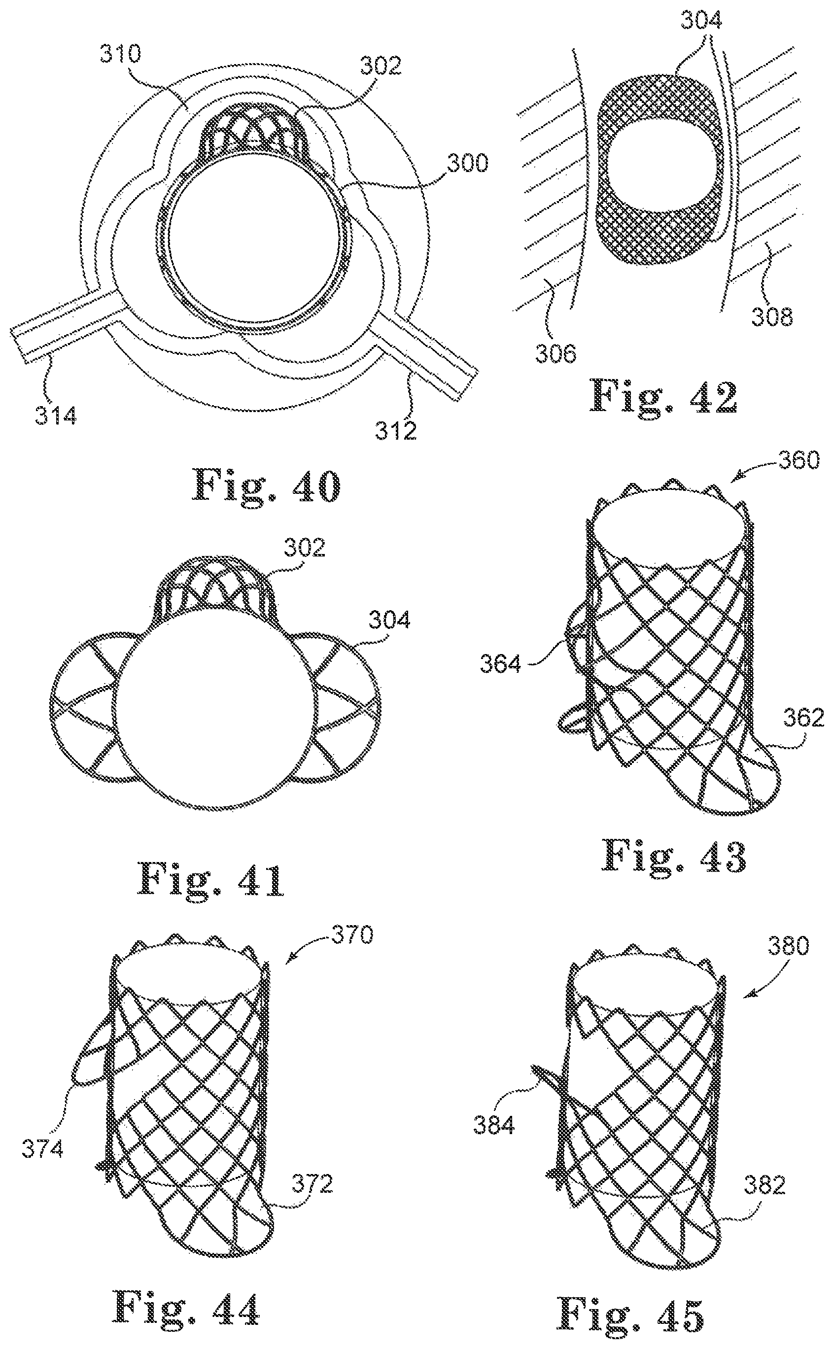
D00016
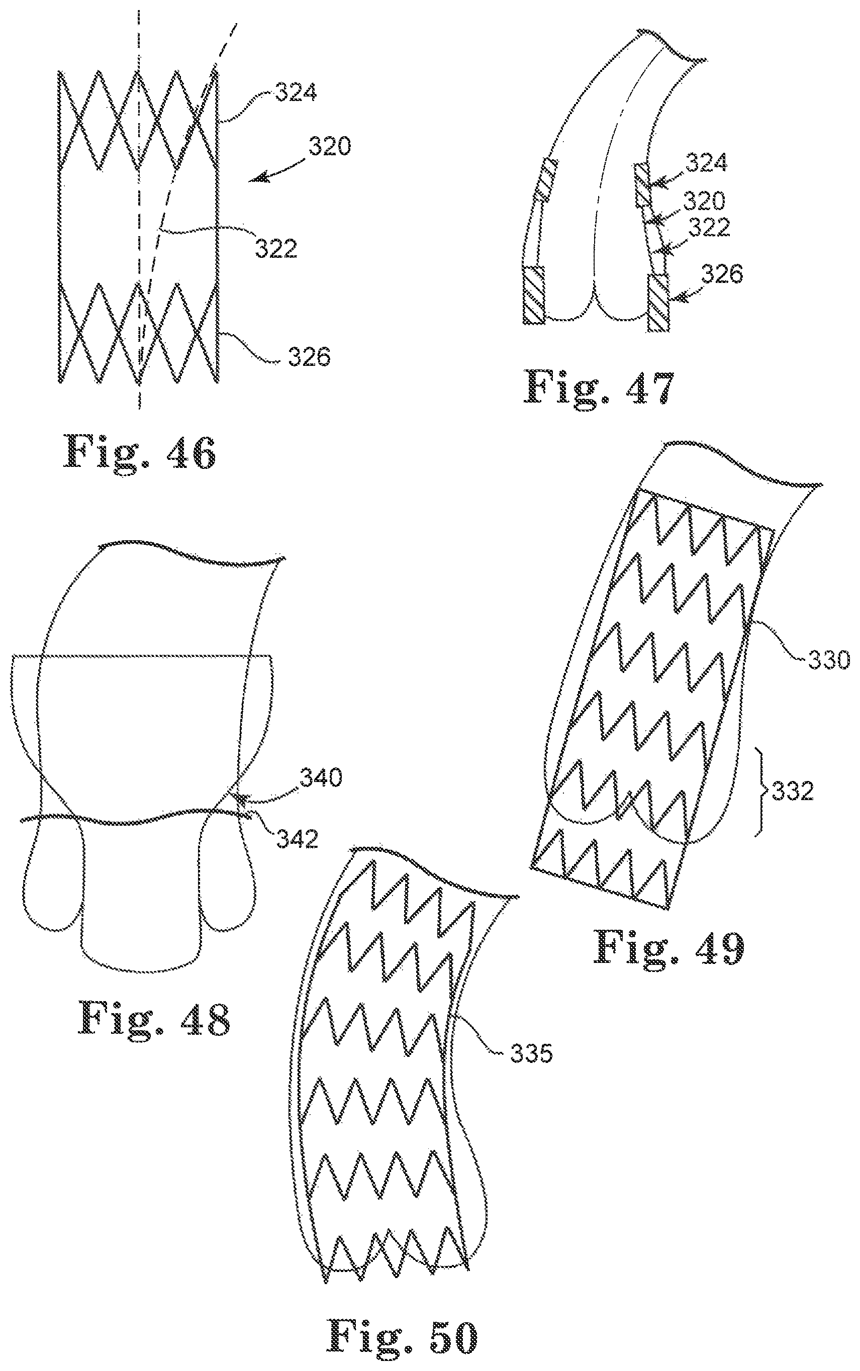
D00017

XML
uspto.report is an independent third-party trademark research tool that is not affiliated, endorsed, or sponsored by the United States Patent and Trademark Office (USPTO) or any other governmental organization. The information provided by uspto.report is based on publicly available data at the time of writing and is intended for informational purposes only.
While we strive to provide accurate and up-to-date information, we do not guarantee the accuracy, completeness, reliability, or suitability of the information displayed on this site. The use of this site is at your own risk. Any reliance you place on such information is therefore strictly at your own risk.
All official trademark data, including owner information, should be verified by visiting the official USPTO website at www.uspto.gov. This site is not intended to replace professional legal advice and should not be used as a substitute for consulting with a legal professional who is knowledgeable about trademark law.