System and method for dual-band backhaul radio
Hinman , et al. October 20, 2
U.S. patent number 10,812,994 [Application Number 16/276,611] was granted by the patent office on 2020-10-20 for system and method for dual-band backhaul radio. This patent grant is currently assigned to Mimosa Networks, Inc.. The grantee listed for this patent is Mimosa Networks, Inc.. Invention is credited to Jaime Fink, Brian L. Hinman, Mustafa Rangwala.


| United States Patent | 10,812,994 |
| Hinman , et al. | October 20, 2020 |
System and method for dual-band backhaul radio
Abstract
A method and system are provided. The system includes a communication system including a first transmitter/receiver operating on a first frequency and a second transmitter/receiver operating on a second frequency. The system also includes a controller monitoring at least one of interference and throughput on the first and second transmitter/receiver and shifting demand based on the monitoring.
| Inventors: | Hinman; Brian L. (Los Gatos, CA), Fink; Jaime (San Francisco, CA), Rangwala; Mustafa (Sunnyvale, CA) | ||||||||||
|---|---|---|---|---|---|---|---|---|---|---|---|
| Applicant: |
|
||||||||||
| Assignee: | Mimosa Networks, Inc. (Santa
Clara, CA) |
||||||||||
| Family ID: | 51487792 | ||||||||||
| Appl. No.: | 16/276,611 | ||||||||||
| Filed: | February 14, 2019 |
Prior Publication Data
| Document Identifier | Publication Date | |
|---|---|---|
| US 20190182686 A1 | Jun 13, 2019 | |
Related U.S. Patent Documents
| Application Number | Filing Date | Patent Number | Issue Date | ||
|---|---|---|---|---|---|
| 15904220 | Feb 23, 2018 | 10257722 | |||
| 15246094 | Apr 17, 2018 | 9949147 | |||
| 14833038 | Dec 12, 2017 | 9843940 | |||
| 14183329 | Nov 17, 2015 | 9191081 | |||
| 61775408 | Mar 8, 2013 | ||||
| Current U.S. Class: | 1/1 |
| Current CPC Class: | H04B 1/0475 (20130101); H04W 36/20 (20130101); H04W 8/26 (20130101); H04B 7/0413 (20130101); H04W 24/08 (20130101); H04W 24/02 (20130101); H04B 7/0469 (20130101); H04W 72/0453 (20130101); H04B 7/068 (20130101) |
| Current International Class: | H04W 24/02 (20090101); H04B 7/0413 (20170101); H04B 7/06 (20060101); H04B 1/04 (20060101); H04B 7/0456 (20170101); H04W 24/08 (20090101); H04W 36/20 (20090101); H04W 72/04 (20090101); H04W 8/26 (20090101) |
References Cited [Referenced By]
U.S. Patent Documents
| 2735993 | February 1956 | Humphrey |
| 3182129 | May 1965 | Clark et al. |
| D227476 | June 1973 | Kennedy |
| 4188633 | February 1980 | Frazita |
| 4402566 | September 1983 | Powell et al. |
| D273111 | March 1984 | Hirata et al. |
| 4543579 | September 1985 | Teshirogi |
| 4562416 | December 1985 | Sedivec |
| 4626863 | December 1986 | Knop et al. |
| 4835538 | May 1989 | McKenna et al. |
| 4866451 | September 1989 | Chen |
| 4893288 | January 1990 | Maier et al. |
| 4903033 | February 1990 | Tsao et al. |
| 4986764 | January 1991 | Eaby et al. |
| 5015195 | May 1991 | Piriz |
| 5087920 | February 1992 | Tsurumaru et al. |
| 5226837 | July 1993 | Cinibulk et al. |
| 5231406 | July 1993 | Sreenivas |
| D346598 | May 1994 | McCay et al. |
| D355416 | February 1995 | McCay et al. |
| 5389941 | February 1995 | Yu |
| 5491833 | February 1996 | Hamabe |
| 5513380 | April 1996 | Ivanov et al. |
| 5539361 | July 1996 | Davidovitz |
| 5561434 | October 1996 | Yamazaki |
| D375501 | November 1996 | Lee et al. |
| 5580264 | December 1996 | Aoyama et al. |
| 5684495 | November 1997 | Dyott et al. |
| D389575 | January 1998 | Grasfield et al. |
| 5724666 | March 1998 | Dent |
| 5742911 | April 1998 | Dumbrill et al. |
| 5746611 | May 1998 | Brown et al. |
| 5764696 | June 1998 | Barnes et al. |
| 5797083 | August 1998 | Anderson |
| 5831582 | November 1998 | Muhlhauser et al. |
| 5966102 | October 1999 | Runyon |
| 5995063 | November 1999 | Somoza et al. |
| 6014372 | January 2000 | Kent et al. |
| 6067053 | May 2000 | Runyon et al. |
| 6137449 | October 2000 | Kildal |
| 6140962 | October 2000 | Groenenboom |
| 6176739 | January 2001 | Denlinger et al. |
| 6216266 | April 2001 | Eastman et al. |
| 6271802 | August 2001 | Clark et al. |
| 6304762 | October 2001 | Myers et al. |
| D455735 | April 2002 | Winslow |
| 6421538 | July 2002 | Byrne |
| 6716063 | April 2004 | Bryant et al. |
| 6754511 | June 2004 | Halford et al. |
| 6847653 | January 2005 | Smiroldo |
| D501848 | February 2005 | Uehara et al. |
| 6853336 | February 2005 | Asano et al. |
| 6877277 | April 2005 | Kussel et al. |
| 6962445 | November 2005 | Zimmel et al. |
| 7075492 | July 2006 | Chen et al. |
| D533899 | December 2006 | Ohashi et al. |
| 7173570 | February 2007 | Wensink et al. |
| 7187328 | March 2007 | Tanaka et al. |
| 7193562 | March 2007 | Shtrom et al. |
| 7212162 | May 2007 | Jung et al. |
| 7212163 | May 2007 | Huang et al. |
| 7245265 | July 2007 | Kienzle et al. |
| 7253783 | August 2007 | Chiang et al. |
| 7264494 | September 2007 | Kennedy et al. |
| 7281856 | October 2007 | Grzegorzewska et al. |
| 7292198 | November 2007 | Shtrom et al. |
| 7306485 | December 2007 | Masuzaki |
| 7316583 | January 2008 | Mistarz |
| 7324057 | January 2008 | Argaman et al. |
| D566698 | April 2008 | Choi et al. |
| 7362236 | April 2008 | Hoiness |
| 7369095 | May 2008 | Hirtzlin et al. |
| 7380984 | June 2008 | Wuester |
| 7431602 | October 2008 | Corona |
| 7498896 | March 2009 | Shi |
| 7498996 | March 2009 | Shtrom et al. |
| 7507105 | March 2009 | Peters et al. |
| 7522095 | April 2009 | Wasiewicz et al. |
| 7542717 | June 2009 | Green, Sr. et al. |
| 7581976 | September 2009 | Liepold et al. |
| 7586891 | September 2009 | Masciulli |
| 7616959 | November 2009 | Spenik et al. |
| 7646343 | January 2010 | Shtrom et al. |
| 7675473 | March 2010 | Kienzle et al. |
| 7675474 | March 2010 | Shtrom et al. |
| 7726997 | June 2010 | Kennedy et al. |
| 7778226 | August 2010 | Rayzman et al. |
| 7857523 | December 2010 | Masuzaki |
| 7929914 | April 2011 | Tegreene |
| RE42522 | July 2011 | Zimmel et al. |
| 8009646 | August 2011 | Lastinger et al. |
| 8069465 | November 2011 | Bartholomay et al. |
| 8111678 | February 2012 | Lastinger et al. |
| 8254844 | August 2012 | Kuffner et al. |
| 8270383 | September 2012 | Lastinger et al. |
| 8275265 | September 2012 | Kobyakov et al. |
| 8325695 | December 2012 | Lastinger et al. |
| D674787 | January 2013 | Tsuda et al. |
| 8345651 | January 2013 | Lastinger et al. |
| 8385305 | February 2013 | Negus et al. |
| 8425260 | April 2013 | Seefried et al. |
| 8482478 | July 2013 | Hartenstein |
| 8515434 | August 2013 | Narendran et al. |
| 8515495 | August 2013 | Shang et al. |
| D694740 | December 2013 | Apostolakis |
| 8777660 | July 2014 | Chiarelli et al. |
| 8792759 | July 2014 | Benton et al. |
| 8827729 | September 2014 | Gunreben et al. |
| 8836601 | September 2014 | Sanford et al. |
| 8848389 | September 2014 | Kawamura et al. |
| 8870069 | October 2014 | Bellows |
| 8935122 | January 2015 | Stisser |
| 9001689 | April 2015 | Hinman et al. |
| 9019874 | April 2015 | Choudhury et al. |
| 9077071 | July 2015 | Shtrom et al. |
| 9107134 | August 2015 | Belser et al. |
| 9130305 | September 2015 | Ramos et al. |
| 9161387 | October 2015 | Fink et al. |
| 9179336 | November 2015 | Fink et al. |
| 9191081 | November 2015 | Hinman et al. |
| D752566 | March 2016 | Hinman et al. |
| 9295103 | March 2016 | Fink et al. |
| 9362629 | June 2016 | Hinman et al. |
| 9391375 | July 2016 | Bales et al. |
| 9407012 | August 2016 | Shtrom et al. |
| 9431702 | August 2016 | Hartenstein |
| 9504049 | November 2016 | Hinman et al. |
| 9531114 | December 2016 | Ramos et al. |
| 9537204 | January 2017 | Cheng et al. |
| 9577340 | February 2017 | Fakharzadeh et al. |
| 9693388 | June 2017 | Fink et al. |
| 9780892 | October 2017 | Hinman et al. |
| 9843940 | December 2017 | Hinman et al. |
| 9871302 | January 2018 | Hinman et al. |
| 9888485 | February 2018 | Hinman et al. |
| 9930592 | March 2018 | Hinman |
| 9949147 | April 2018 | Hinman et al. |
| 9986565 | May 2018 | Fink et al. |
| 9998246 | June 2018 | Hinman et al. |
| 10028154 | July 2018 | Elson |
| 10090943 | October 2018 | Hinman et al. |
| 10096933 | October 2018 | Ramos et al. |
| 10117114 | October 2018 | Hinman et al. |
| 10186786 | January 2019 | Hinman et al. |
| 10200925 | February 2019 | Hinman |
| 10257722 | April 2019 | Hinman et al. |
| 10425944 | September 2019 | Fink et al. |
| 10447417 | October 2019 | Hinman et al. |
| 10511074 | December 2019 | Eberhardt et al. |
| 10595253 | March 2020 | Hinman |
| 10714805 | July 2020 | Eberhardt et al. |
| 10742275 | August 2020 | Hinman |
| 10749263 | August 2020 | Eberhardt et al. |
| 2001/0033600 | October 2001 | Yang et al. |
| 2002/0102948 | August 2002 | Stanwood et al. |
| 2002/0159434 | October 2002 | Gosior et al. |
| 2003/0013452 | January 2003 | Hunt et al. |
| 2003/0027577 | February 2003 | Brown et al. |
| 2003/0169763 | September 2003 | Choi |
| 2003/0222831 | December 2003 | Dunlap |
| 2003/0224741 | December 2003 | Sugar et al. |
| 2004/0002357 | January 2004 | Benveniste |
| 2004/0029549 | February 2004 | Fikart |
| 2004/0110469 | June 2004 | Judd et al. |
| 2004/0120277 | June 2004 | Holur et al. |
| 2004/0155819 | August 2004 | Martin et al. |
| 2004/0196812 | October 2004 | Barber |
| 2004/0196813 | October 2004 | Ofek et al. |
| 2004/0240376 | December 2004 | Wang et al. |
| 2004/0242274 | December 2004 | Corbett et al. |
| 2005/0032479 | February 2005 | Miller et al. |
| 2005/0058111 | March 2005 | Hung et al. |
| 2005/0124294 | June 2005 | Wentink |
| 2005/0143014 | June 2005 | Li et al. |
| 2005/0152323 | July 2005 | Bonnassieux et al. |
| 2005/0195758 | September 2005 | Chitrapu |
| 2005/0227625 | October 2005 | Diener |
| 2005/0254442 | November 2005 | Proctor, Jr. et al. |
| 2005/0271056 | December 2005 | Kaneko |
| 2005/0275527 | December 2005 | Kates |
| 2006/0025072 | February 2006 | Pan |
| 2006/0072518 | April 2006 | Pan et al. |
| 2006/0098592 | May 2006 | Proctor, Jr. et al. |
| 2006/0099940 | May 2006 | Pfleging et al. |
| 2006/0132359 | June 2006 | Chang et al. |
| 2006/0132602 | June 2006 | Muto et al. |
| 2006/0172578 | August 2006 | Parsons |
| 2006/0187952 | August 2006 | Kappes et al. |
| 2006/0211430 | September 2006 | Persico |
| 2006/0276073 | December 2006 | McMurray et al. |
| 2007/0001910 | January 2007 | Yamanaka et al. |
| 2007/0019664 | January 2007 | Benveniste |
| 2007/0035463 | February 2007 | Hirabayashi |
| 2007/0060158 | March 2007 | Medepalli et al. |
| 2007/0132643 | June 2007 | Durham et al. |
| 2007/0173199 | July 2007 | Sinha |
| 2007/0173260 | July 2007 | Love et al. |
| 2007/0202809 | August 2007 | Lastinger et al. |
| 2007/0210974 | September 2007 | Chiang |
| 2007/0223701 | September 2007 | Emeott et al. |
| 2007/0238482 | October 2007 | Rayzman et al. |
| 2007/0255797 | November 2007 | Dunn et al. |
| 2007/0268848 | November 2007 | Khandekar et al. |
| 2008/0109051 | May 2008 | Splinter et al. |
| 2008/0112380 | May 2008 | Fischer |
| 2008/0192707 | August 2008 | Xhafa et al. |
| 2008/0218418 | September 2008 | Gillette |
| 2008/0231541 | September 2008 | Teshirogi et al. |
| 2008/0242342 | October 2008 | Rofougaran |
| 2009/0046673 | February 2009 | Kaidar |
| 2009/0051597 | February 2009 | Wen et al. |
| 2009/0052362 | February 2009 | Meier et al. |
| 2009/0059794 | March 2009 | Frei |
| 2009/0075606 | March 2009 | Shtrom et al. |
| 2009/0096699 | April 2009 | Chiu et al. |
| 2009/0232026 | September 2009 | Lu |
| 2009/0233475 | September 2009 | Mildon et al. |
| 2009/0291690 | November 2009 | Guvenc et al. |
| 2009/0315792 | December 2009 | Miyashita et al. |
| 2010/0029282 | February 2010 | Stamoulis et al. |
| 2010/0039340 | February 2010 | Brown |
| 2010/0046650 | February 2010 | Jongren et al. |
| 2010/0067505 | March 2010 | Fein et al. |
| 2010/0085950 | April 2010 | Sekiya |
| 2010/0091818 | April 2010 | Sen et al. |
| 2010/0103065 | April 2010 | Shtrom et al. |
| 2010/0103066 | April 2010 | Shtrom et al. |
| 2010/0136978 | June 2010 | Cho et al. |
| 2010/0151877 | June 2010 | Lee et al. |
| 2010/0167719 | July 2010 | Sun |
| 2010/0171665 | July 2010 | Nogami |
| 2010/0171675 | July 2010 | Borja et al. |
| 2010/0177660 | July 2010 | Essinger et al. |
| 2010/0189005 | July 2010 | Bertani et al. |
| 2010/0202613 | August 2010 | Ray et al. |
| 2010/0210147 | August 2010 | Hauser |
| 2010/0216412 | August 2010 | Rofougaran |
| 2010/0225529 | September 2010 | Landreth et al. |
| 2010/0238083 | September 2010 | Malasani |
| 2010/0304680 | December 2010 | Kuffner et al. |
| 2010/0311321 | December 2010 | Norin |
| 2010/0315307 | December 2010 | Syed et al. |
| 2010/0322219 | December 2010 | Fischer et al. |
| 2011/0006956 | January 2011 | McCown |
| 2011/0028097 | February 2011 | Memik et al. |
| 2011/0032159 | February 2011 | Wu et al. |
| 2011/0044186 | February 2011 | Jung et al. |
| 2011/0090129 | April 2011 | Weily et al. |
| 2011/0103309 | May 2011 | Wang et al. |
| 2011/0111715 | May 2011 | Buer et al. |
| 2011/0112717 | May 2011 | Resner |
| 2011/0133996 | June 2011 | Alapuranen |
| 2011/0170424 | July 2011 | Safavi |
| 2011/0172916 | July 2011 | Pakzad et al. |
| 2011/0182260 | July 2011 | Sivakumar et al. |
| 2011/0182277 | July 2011 | Shapira |
| 2011/0194644 | August 2011 | Liu et al. |
| 2011/0206012 | August 2011 | Youn et al. |
| 2011/0241969 | October 2011 | Zhang et al. |
| 2011/0243291 | October 2011 | McAllister et al. |
| 2011/0256874 | October 2011 | Hayama et al. |
| 2011/0291914 | December 2011 | Lewry et al. |
| 2012/0008542 | January 2012 | Koleszar et al. |
| 2012/0040700 | February 2012 | Gomes et al. |
| 2012/0057533 | March 2012 | Junell et al. |
| 2012/0093091 | April 2012 | Kang et al. |
| 2012/0115487 | May 2012 | Josso |
| 2012/0134280 | May 2012 | Rotvold et al. |
| 2012/0140651 | June 2012 | Nicoara et al. |
| 2012/0200449 | August 2012 | Bielas |
| 2012/0238201 | September 2012 | Du et al. |
| 2012/0263145 | October 2012 | Marinier et al. |
| 2012/0282868 | November 2012 | Hahn |
| 2012/0299789 | November 2012 | Orban et al. |
| 2012/0314634 | December 2012 | Sekhar |
| 2013/0003645 | January 2013 | Shapira et al. |
| 2013/0005350 | January 2013 | Campos et al. |
| 2013/0023216 | January 2013 | Moscibroda et al. |
| 2013/0044028 | February 2013 | Lea et al. |
| 2013/0064161 | March 2013 | Hedayat et al. |
| 2013/0082899 | April 2013 | Gomi |
| 2013/0095747 | April 2013 | Moshfeghi |
| 2013/0128858 | May 2013 | Zou et al. |
| 2013/0176902 | July 2013 | Wentink et al. |
| 2013/0182652 | July 2013 | Tong et al. |
| 2013/0195081 | August 2013 | Merlin et al. |
| 2013/0210457 | August 2013 | Kummetz |
| 2013/0223398 | August 2013 | Li et al. |
| 2013/0234898 | September 2013 | Leung et al. |
| 2013/0271319 | October 2013 | Trerise |
| 2013/0286950 | October 2013 | Pu |
| 2013/0286959 | October 2013 | Lou et al. |
| 2013/0288735 | October 2013 | Guo |
| 2013/0301438 | November 2013 | Li et al. |
| 2013/0322276 | December 2013 | Pelletier et al. |
| 2013/0322413 | December 2013 | Pelletier et al. |
| 2014/0024328 | January 2014 | Balbien et al. |
| 2014/0051357 | February 2014 | Steer et al. |
| 2014/0098748 | April 2014 | Chan et al. |
| 2014/0113676 | April 2014 | Hamalainen et al. |
| 2014/0145890 | May 2014 | Ramberg |
| 2014/0154895 | June 2014 | Poulsen et al. |
| 2014/0185494 | July 2014 | Yang et al. |
| 2014/0191918 | July 2014 | Cheng et al. |
| 2014/0198867 | July 2014 | Sturkovich et al. |
| 2014/0206322 | July 2014 | Dimou et al. |
| 2014/0225788 | August 2014 | Schulz et al. |
| 2014/0233613 | August 2014 | Fink et al. |
| 2014/0235244 | August 2014 | Hinman |
| 2014/0253378 | September 2014 | Hinman |
| 2014/0253402 | September 2014 | Hinman et al. |
| 2014/0254700 | September 2014 | Hinman et al. |
| 2014/0256166 | September 2014 | Ramos et al. |
| 2014/0320306 | October 2014 | Winter |
| 2014/0320377 | October 2014 | Cheng et al. |
| 2014/0328238 | November 2014 | Seok et al. |
| 2014/0355578 | December 2014 | Fink et al. |
| 2014/0355584 | December 2014 | Fink et al. |
| 2015/0002335 | January 2015 | Hinman et al. |
| 2015/0002354 | January 2015 | Knowles |
| 2015/0015435 | January 2015 | Shen et al. |
| 2015/0116177 | April 2015 | Powell et al. |
| 2015/0156642 | June 2015 | Sobczak et al. |
| 2015/0215952 | July 2015 | Hinman et al. |
| 2015/0256275 | September 2015 | Hinman et al. |
| 2015/0263816 | September 2015 | Hinman et al. |
| 2015/0319584 | November 2015 | Fink et al. |
| 2015/0321017 | November 2015 | Perryman et al. |
| 2015/0325945 | November 2015 | Ramos et al. |
| 2015/0327272 | November 2015 | Fink et al. |
| 2015/0365866 | December 2015 | Hinman et al. |
| 2016/0119018 | April 2016 | Lindgren et al. |
| 2016/0149634 | May 2016 | Kalkunte et al. |
| 2016/0149635 | May 2016 | Hinman et al. |
| 2016/0211583 | July 2016 | Lee et al. |
| 2016/0240929 | August 2016 | Hinman et al. |
| 2016/0338076 | November 2016 | Hinman et al. |
| 2016/0365666 | December 2016 | Ramos et al. |
| 2016/0366601 | December 2016 | Hinman et al. |
| 2017/0048647 | February 2017 | Jung et al. |
| 2017/0201028 | July 2017 | Eberhardt et al. |
| 2017/0238151 | August 2017 | Fink et al. |
| 2017/0294975 | October 2017 | Hinman et al. |
| 2017/0353245 | December 2017 | Vardarajan et al. |
| 2018/0034166 | February 2018 | Hinman |
| 2018/0035317 | February 2018 | Hinman et al. |
| 2018/0083365 | March 2018 | Hinman et al. |
| 2018/0084563 | March 2018 | Hinman et al. |
| 2018/0160353 | June 2018 | Hinman |
| 2018/0192305 | July 2018 | Hinman et al. |
| 2018/0199345 | July 2018 | Fink et al. |
| 2018/0241491 | August 2018 | Hinman et al. |
| 2019/0006789 | January 2019 | Ramos et al. |
| 2019/0214699 | July 2019 | Eberhardt et al. |
| 2019/0215745 | July 2019 | Hinman |
| 2019/0273326 | September 2019 | Sanford et al. |
| 2020/0015231 | January 2020 | Fink et al. |
| 2020/0036465 | January 2020 | Hinman et al. |
| 2020/0067164 | February 2020 | Eberhardt et al. |
| 2020/0083614 | March 2020 | Sanford et al. |
| 104335654 | Feb 2015 | CN | |||
| 303453662 | Nov 2015 | CN | |||
| 105191204 | Dec 2015 | CN | |||
| 105191204 | May 2019 | CN | |||
| 002640177 | Feb 2015 | EM | |||
| 1384285 | Jun 2007 | EP | |||
| 3491697 | Jun 2019 | EP | |||
| WO2014137370 | Sep 2014 | WO | |||
| WO2014138292 | Sep 2014 | WO | |||
| WO2014193394 | Dec 2014 | WO | |||
| WO2015112627 | Jul 2015 | WO | |||
| WO2017123558 | Jul 2017 | WO | |||
| WO2018022526 | Feb 2018 | WO | |||
| WO2019136257 | Jul 2019 | WO | |||
| WO2019168800 | Sep 2019 | WO | |||
Other References
|
"Sector Antennas," Radiowaves.com, [online], [retrieved Oct. 10, 2019], Retrieved from the Internet: <URL:https://www.radiowaves.com/en/products/sector-antennas>, 4 pages. cited by applicant . KP Performance Antennas Search Results for Antennas, Sector, Single, [online], KPPerformance.com [retrieved Oct. 10, 2019], Retrieved from the Internet: <URL:https://www.kpperformance.com/search? Category=Antennas&Rfpsan99design=Sector&Rfpsan99option=Single&view_type=g- rid>, 6 pages. cited by applicant . "Partial Supplemental European Search Report," European Patent Application No. 17835073.2, dated Feb. 13, 2020, 17 pages. cited by applicant . "Wireless Access Point," Wikipedia.org, Jan. 6, 2020 [retrieved on Feb. 3, 2020], Retrieved from the Internet: <https://en.wikipedia.org/wiki/Wireless_access_point>, 5 pages. cited by applicant . "International Search Report" and "Written Opinion of the International Search Authority," dated Nov. 26, 2013 in Patent Cooperation Treaty Application No. PCT/US2013/047406, filed Jun. 24, 2013, 9 pages. cited by applicant . "International Search Report" and "Written Opinion of the International Search Authority," dated Aug. 9, 2013 in Patent Cooperation Treaty Application No. PCT/US2013/043436, filed May 30, 2013, 13 pages. cited by applicant . "International Search Report" and "Written Opinion of the International Search Authority," dated Jul. 1, 2014 in Patent Cooperation Treaty Application No. PCT/US2014/020880, filed Mar. 5, 2014, 14 pages. cited by applicant . "International Search Report" and "Written Opinion of the International Search Authority," dated Jun. 29, 2015 in Patent Cooperation Treaty Application No. PCT/US2015/012285, filed Jan. 21, 2015, 15 pages. cited by applicant . Hinman et al., U.S. Appl. No. 61/774,532, filed Mar. 7, 2013, 23 pages. cited by applicant . "Office Action," Chinese Design Patent Application 201530058063.8, dated Jun. 15, 2015, 1 page. cited by applicant . "Notice of Allowance,"Chinese Design Patent Application 201530058063.8, dated Sep. 8, 2015, 3 pages. cited by applicant . Weisstein, Eric, "Electric Polarization", Wolfram Reasearch [online], Retrieved from the Internet [retrieved Mar. 23, 2017] <URL:http://scienceworld.wolfram.com/physics/ElectricPolarization.html- >, 2007, 1 page. cited by applicant . Liu, Lingjia et al., "Downlink MIMO in LTE-Advanced: SU-MIMO vs. MU-MIMO," IEEE Communications Magazine, Feb. 2012, pp. 140-147. cited by applicant . "International Search Report" and "Written Opinion of the International Searching Authority," Patent Cooperation Treaty Application No. PCT/US2017/012884, dated Apr. 6, 2017, 9 pages. cited by applicant . "Office Action," Chinese Patent Application No. 201580000078.6, dated Nov. 3, 2017, 5 pages [10 pages including translation]. cited by applicant . "International Search Report" and "Written Opinion of the International Searching Authority," Patent Cooperation Treaty Application No. PCT/US2017/043560, dated Nov. 16, 2017, 11 pages. cited by applicant . "Office Action," Chinese Patent Application No. 201580000078.6, dated Jul. 30, 2018, 5 pages [11 pages including translation]. cited by applicant . "Office Action," Chinese Patent Application No. 201580000078.6, dated Oct. 31, 2018, 3 pages [6 pages including translation]. cited by applicant . "Notice of Allowance," Chinese Patent Application No. 201580000078.6, dated Feb. 11, 2019, 2 pages. cited by applicant . "International Search Report" and "Written Opinion of the International Search Authority," dated Mar. 22, 2019 in Patent Cooperation Treaty Application No. PCT/US2019/012358, filed Jan. 4, 2019, 9 pages. cited by applicant . FCC Regulations, 47 CFR .sctn. 15.407, 63 FR 40836, Jul. 31, 1998, as amended at 69 FR 2687, Jan. 20, 2004; 69 FR 54036, Sep. 7, 2004; pp. 843-846. cited by applicant . "International Search Report" and "Written Opinion of the International Search Authority," dated May 23, 2019 in Patent Cooperation Treaty Application No. PCT/US2019/019462, filed Feb. 25, 2019, 8 pages. cited by applicant . Teshirogi, Tasuku et al., "Wideband Circularly Polarized Array Antenna with Sequential Rotations and Phase Shift of Elements," Proceedings of the International Symposium on Antennas and Propagation, 1985, pp. 117-120. cited by applicant . "Extended European Search Report", European Patent Application No. 17835073.2, dated Jun. 30, 2020, 15 pages. cited by applicant . Haupt, R.T., "Antenna Arrays: A Computational Approach", Chapter 5: Non-Planar Arrays; Wiley-IEEE Press (2010), pp. 287-338. cited by applicant. |
Primary Examiner: Baig; Adnan
Attorney, Agent or Firm: Carr & Ferrell LLP
Parent Case Text
CROSS REFERENCE TO RELATED APPLICATIONS
This Non-Provisional U.S. patent application is a continuation of and claims the benefit of Non-Provisional U.S. patent application Ser. No. 15/904,220, filed on Feb. 23, 2018, now U.S. Pat. No. 10,257,722, issued Apr. 9, 2019, which is a continuation of and claims the benefit of Non-Provisional U.S. patent application Ser. No. 15/246,094, filed on Aug. 24, 2016, now U.S. Pat. No. 91949,147, issued Apr. 17, 2018, which is a continuation of and claims the benefit of Non-Provisional U.S. patent application Ser. No. 14/833,038, filed on Aug. 21, 2015, now U.S. Pat. No. 9,843,940, issued Dec. 12, 2017, which is a continuation of and claims the benefit of Non-Provisional U.S. patent application Ser. No. 14/183,329, filed on Feb. 18, 2014, now U.S. Pat. No. 9,191,081, issued Nov. 17, 2015, which in turn claims the benefit of U.S. Provisional Application Ser. No. 61/775,408, filed on Mar. 8, 2013. All of the aforementioned disclosures are hereby incorporated by reference herein in their entireties including all references and appendices cited therein.
Claims
What is claimed is:
1. A dual-band 4.times.4 MIMO radio, comprising: two orthogonal antennas, each of the two orthogonal antennas transmitting or receiving data on dual channels in a first frequency using a multiple-input-multiple-output (MIMO) baseband processor that places two signals in orthogonal polarization using radio frequency (RF) two converters that are tuned to different channels within the first frequency to produce four data streams; and custom RF front-end that provides optimal performance on a receiver noise figure by sharing a low noise amplifier for the dual channels on the same polarization, the custom RF front-end further comprising two distinct power amplifiers for the two orthogonal antennas that provide isolation between the dual channels to avoid intermodulation distortion, wherein outputs of the power amplifiers are combined using a hybrid combiner and a transmit-receive switch that receives the outputs of the power amplifiers, the transmit-receive switch being coupled to the two orthogonal antennas.
2. The dual-band 4.times.4 MIMO radio according to claim 1, further comprising a quadrature amplitude modulation decoder that separates the four data streams from the dual-band 4.times.4 MIMO radio.
3. The dual-band 4.times.4 MIMO radio according to claim 1, wherein the two orthogonal antennas are coupled to four antenna probes within coaxial waveguides.
4. The dual-band 4.times.4 MIMO radio according to claim 3, wherein the two orthogonal antennas and the four antenna probes are housed within a single dish housing.
5. The dual-band 4.times.4 MIMO radio according to claim 4, wherein two of the four antenna probes are housed within a first waveguide and another two of the four antenna probes are housed within a second waveguide.
6. The dual-band 4.times.4 MIMO radio according to claim 5, wherein the first waveguide is concentric with the second waveguide.
7. The dual-band 4.times.4 MIMO radio according to claim 6, wherein the two of the four antenna probes that are housed within the first waveguide are vertically polarized.
8. The dual-band 4.times.4 MIMO radio according to claim 7, wherein the another two of the four antenna probes that are housed within the second waveguide are horizontally polarized.
9. The dual-band 4.times.4 MIMO radio according to claim 1, wherein the MIMO baseband processor comprises a 4.times.4 baseband processor.
10. The dual-band 4.times.4 MIMO radio according to claim 1, wherein the two converters each comprise a 2.times.2 RF chipset.
11. The dual-band 4.times.4 MIMO radio according to claim 10, wherein a first of the two converters is coupled with a splitter that couples with the low noise amplifier.
12. The dual-band 4.times.4 MIMO radio according to claim 11, wherein the first of the two converters is coupled with one of the two distinct power amplifiers.
13. A system, comprising: a 4.times.4 multiple-input-multiple-output (MIMO) baseband processor; and a pair of radio-frequency front-ends, each comprising: a splitter that couples with a first converter that couples with the 4.times.4 multiple-input-multiple-output (MIMO) baseband processor; two distinct power amplifiers, a first of the two distinct power amplifiers coupled with a second converter that couples with the 4.times.4 multiple-input-multiple-output (MIMO) baseband processor; a low-noise amplifier that couples with the splitter; a hybrid combiner that is coupled to both of the two distinct power amplifiers; and a transmit-receive switch coupled to both the low-noise amplifier and the hybrid combiner.
14. The system according to claim 13, further comprising two orthogonal antennas coupled to the transmit-receive switch.
15. The system according to claim 14, wherein each of the two orthogonal antennas transmits or receives data on dual channels in a first frequency as controlled by the 4.times.4 multiple-input-multiple-output (MIMO) baseband processor.
16. The system according to claim 15, wherein the 4.times.4 multiple-input-multiple-output (MIMO) baseband processor places two signals in orthogonal polarization using radio frequency (RF) two converters that are tuned to different channels within the first frequency to produce four data streams.
17. The system according to claim 15, wherein a first of the pair of radio-frequency front-ends operates in the first frequency and a second of the pair of radio-frequency front-ends operates in a second frequency.
18. The system according to claim 17, wherein the first frequency comprises 5 GHz and the second frequency comprises 24 GHz.
Description
FIELD OF THE INVENTION
The present invention relates to systems and methods for a dual-band backhaul radio. In particular, the present system and method enables higher reliability data transmission radios by utilizing more than one frequency band to leverage uncorrelated interference between frequency bands.
BACKGROUND
MIMO systems in general utilize multiple antennas at both the transmitter and receiver to improve communication performance between the transmitter and receiver. MIMO systems may allow for the communication of different information on each of a plurality of antennas via the transmitter, even using the same frequency. These MIMO systems may compensate for both frequency and time discrepancies. Exemplary systems that utilize MIMO technology include, but are not limited to, wireless Internet service providers (ISP), worldwide interoperability for microwave access (WiMAX) systems, and 4G long-term evolution (LTE) data transmission systems.
A master antenna may include a baseband radio and two chains of communication through vertically and horizontally polarized antennas. The master antenna may have a connection for power and data communications, typically shared through an interface such as power-over-Ethernet. A slave antenna connected by coaxial cable to the master antenna includes circuitry to compensate for cable loss and split the transmit and receive paths. The slave antenna provides communication over another pair of vertically and horizontally polarized antennas. With adequate physical separation between the pair of dishes on each end of a long distance link, a phase angle difference between the vertical and horizontal antenna elements allows four distinct channels of communication to occur as a result of MIMO processing.
SUMMARY
According to some embodiments, the present technology may be directed to a dual-band 4.times.4 MIMO radio, comprising: two orthogonal antennas, each of the two orthogonal antennas transmitting or receiving data on dual channels in a first frequency using a multiple-input-multiple-output (MIMO) baseband processor that places two signals in orthogonal polarization using radio frequency (RF) two converters that are tuned to different channels within the first frequency to produce four data streams; and a custom RF front-end provides optimal performance on a receiver noise figure by sharing a low noise amplifier for the dual channels on the same polarization, the custom RF front-end further comprising two distinct power amplifiers for the two orthogonal antennas that provide isolation between the dual channels to avoid intermodulation distortion, wherein outputs of the power amplifiers are combined using a hybrid combiner and a transmit-receive switch that receives the outputs of the power amplifiers, the transmit-receive switch being coupled to the two orthogonal antennas.
The present technology may also be directed to a system comprising: a 4.times.4 multiple-input-multiple-output (MIMO) baseband processor; a pair of custom radio-frequency front-ends, each comprising: a splitter that couples with a first converter that couples with the 4.times.4 multiple-input-multiple-output (MIMO) baseband processor; two distinct power amplifiers, a first of the two distinct power amplifiers coupled with a second converter that couples with the 4.times.4 multiple-input-multiple-output (MIMO) baseband processor; a low-noise amplifier that couples with the splitter; a hybrid combiner that is coupled to both of the two distinct power amplifiers; and a transmit-receive switch coupled to both the low-noise amplifier and the hybrid combiner.
BRIEF DESCRIPTION OF THE DRAWINGS
The accompanying drawings, where like reference numerals refer to identical or functionally similar elements throughout the separate views, together with the detailed description below, are incorporated in and form part of the specification, and serve to further illustrate embodiments of concepts that include the claimed disclosure, and explain various principles and advantages of those embodiments.
The methods and systems disclosed herein have been represented where appropriate by conventional symbols in the drawings, showing only those specific details that are pertinent to understanding the embodiments of the present disclosure so as not to obscure the disclosure with details that will be readily apparent to those of ordinary skill in the art having the benefit of the description herein.
FIG. 1 is a top plan view of single dish radio illustrating two concentric and coaxial waveguides and an exemplary arrangement of two antenna probes in each waveguide.
FIG. 2 is a cross-sectional side view of single dish radio of FIG. 1 in which the two vertical polarized waveguides.
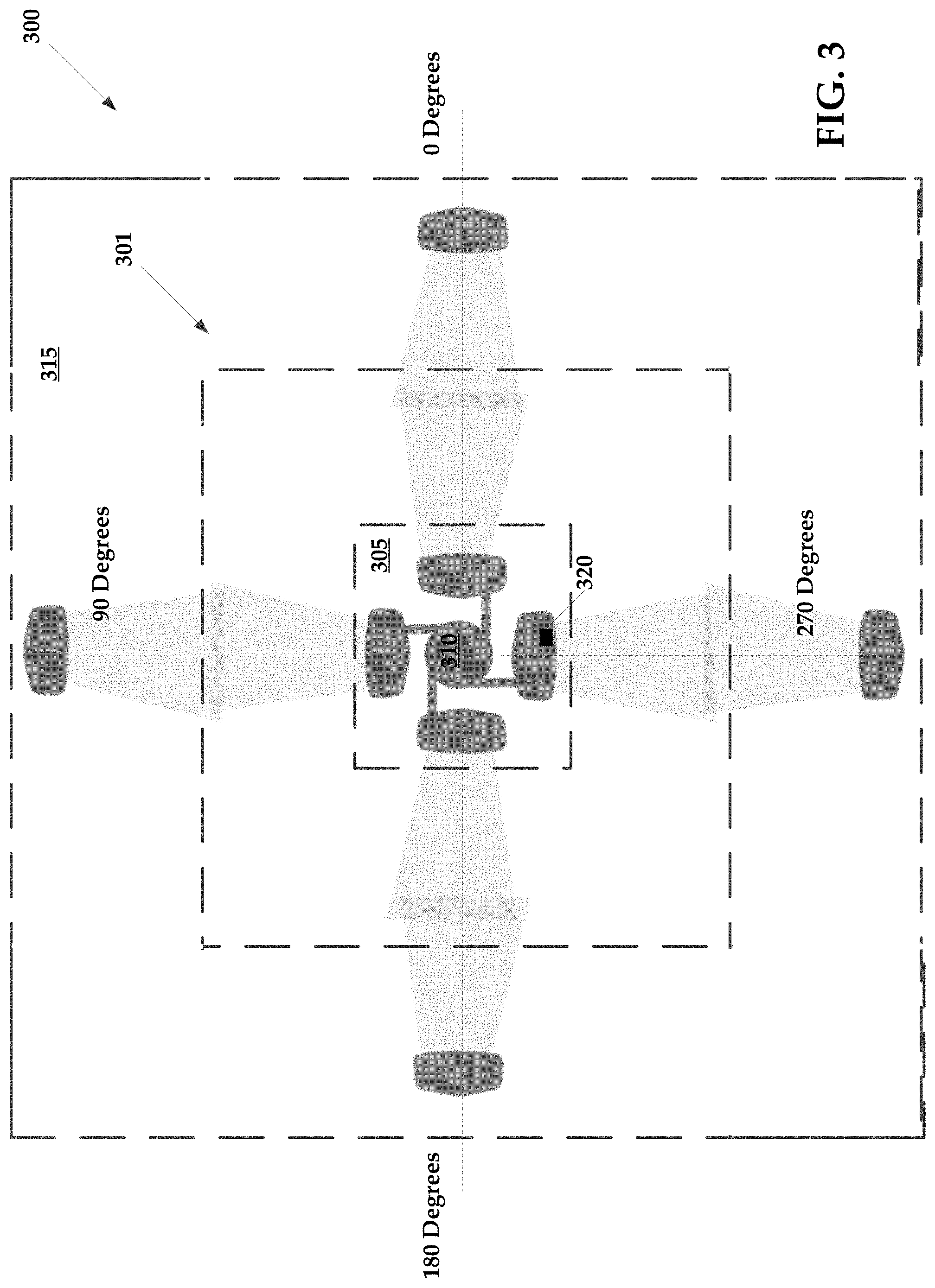
FIG. 3 illustrates an exemplary a portion of an exemplary 4.times.4 MIMO radio system for practicing aspects of the present technology.
FIG. 4 is a flowchart of an exemplary method for multiple input multiple output (MIMO) multi-frequency transmission of data.
FIG. 5 illustrates an exemplary computing system that may be used to implement embodiments according to the present technology.
FIG. 6 illustrates a block diagram for a dual-channel 5 GHz only system.
DESCRIPTION
In the following description, for purposes of explanation, numerous specific details are set forth in order to provide a thorough understanding of the disclosure. It will be apparent, however, to one skilled in the art, that the disclosure may be practiced without these specific details. In other instances, structures and devices are shown at block diagram form only in order to avoid obscuring the disclosure.
Reference throughout this specification to "one embodiment" or "an embodiment" means that a particular feature, structure, or characteristic described in connection with the embodiment is included in at least one embodiment of the present invention. Thus, the appearances of the phrases "in one embodiment" or "in an embodiment" or "according to one embodiment" (or other phrases having similar import) at various places throughout this specification are not necessarily all referring to the same embodiment. Furthermore, the particular features, structures, or characteristics may be combined in any suitable manner in one or more embodiments. Furthermore, depending on the context of discussion herein, a singular term may include its plural forms and a plural term may include its singular form. Similarly, a hyphenated term (e.g., "on-demand") may be occasionally interchangeably used with its non-hyphenated version (e.g., "on demand"), a capitalized entry (e.g., "Software") may be interchangeably used with its non-capitalized version (e.g., "software"), a plural term may be indicated with or without an apostrophe (e.g., PE's or PEs), and an italicized term (e.g., "N+1") may be interchangeably used with its non-italicized version (e.g., "N+1"). Such occasional interchangeable uses shall not be considered inconsistent with each other.
The terminology used herein is for the purpose of describing particular embodiments only and is not intended to be limiting of the invention. As used herein, the singular forms "a", "an" and "the" are intended to include the plural forms as well, unless the context clearly indicates otherwise. It will be further understood that the terms "comprises" and/or "comprising," when used in this specification, specify the presence of stated features, integers, steps, operations, elements, and/or components, but do not preclude the presence or addition of one or more other features, integers, steps, operations, elements, components, and/or groups thereof.
It is noted at the outset that the terms "coupled," "connected", "connecting," "electrically connected," etc., are used interchangeably herein to generally refer to the condition of being electrically/electronically connected. Similarly, a first entity is considered to be in "communication" with a second entity (or entities) when the first entity electrically sends and/or receives (whether through wireline or wireless means) information signals (whether containing data information or non-data/control information) to the second entity regardless of the type (analog or digital) of those signals. It is further noted that various figures (including component diagrams) shown and discussed herein are for illustrative purpose only, and are not drawn to scale.
A dual-band 5 GHz and 24 GHz system (MIMO radio), using 4.times.4 MIMO 802.11 ac, provides four-stream communication. The system places two signals in orthogonal polarizations within each band. Because the outage conditions in the two bands are uncorrelated (24 GHz fades with rain, 5 GHz is impaired by manmade interference), the dual-band radio can provide higher reliability than a single-band radio. Using the provided dual-band backhaul radio, a 1 Gb/sec. transmission rate is possible.
Similarly, such as the system 600 of FIG. 6, a dual-channel 5 GHz only system (MIMO radio), using a 4.times.4 MIMO 802.11 ac, provides four-stream communication. The system places two signals in orthogonal polarization using two orthogonal antennas, such as antenna 605 and 610, each antenna transmitting or receiving on dual channels in the same 5 GHz band. Such a system is realized utilizing a single 4.times.4 baseband processor and dual 2.times.2 RF converters tuned to different channels in the 5 GHz band. A custom RF front-end 615 is utilized that provides an optimal performance on receiver noise figure, by sharing a low noise amplifier 620 for dual channels on the same polarization, while distinct power amplifiers 625 and 630 provide enough isolation between the dual channels to avoid intermodulation distortion. Outputs of the power amplifiers are combined using a hybrid coupler 640 before going to a transmit-receive switch 645 utilized in TDD systems, thus exploiting the same antennas for dual channels. Since 5 GHz impairments are channel specific, the dual-band radio utilizes two channels and can thus provide higher reliability than a single-band radio. Using the provided dual-band backhaul radio, a 1 Gb/sec. transmission rate is possible.
The present technology provides a 4.times.4 MIMO transmission by making the four chains orthogonal through both polarization and frequency. A four stream MIMO link is typically communicated through four transmit and four receive antennas that are not necessarily orthogonal, but which have adequate spatial diversity to allow a pre- and post-processing of the signals to create orthogonality. In the dual-band radio conceived here, the pre- and post-processing may be minimal, since two polarizations (orthogonal) are on one band, and two polarizations (orthogonal) are on another band. The frequency separation creates orthogonality. Two reasons to use a 4.times.4 MIMO radio are (a) it is a relatively inexpensive and available way to aggregate four data streams, and (b) there is likely to be some rotation of the antenna polarizations from end-to-end, which requires a matrix rotation to bring them back into orthogonality before demodulation. The four data streams using two different frequencies and different polarizations within each frequency are inherently orthogonal, which facilitates processing. In particular, a QAM (Quadrature Amplitude Modulation) decoder may be used to separate the four data streams from a dual-band 4.times.4 MIMO radio.
An exemplary implementation of the dual-band radio could be with either two dishes (one for each band), or just a single dish. The two dish solution is simpler to implement, but the single dish may be more desirable due to reduced hardware requirements.
FIGS. 1 and 2 collectively illustrate an exemplary embodiment of a single dish design of a dual-band 4.times.4 MIMO radio 100 for a 5 GHz and 24 GHz system. In single dish radio 100 there may be four antenna probes in coaxial waveguides, for example. Two smaller probes for 24 GHz, which may be about 3 mm long, are placed in horizontal and vertical orientations (or any other 90 degree arrangement) in the inside waveguide. That is, the radio 100 may include a first vertically polarized antenna 105 and a first horizontally polarized antenna 110.
Two longer probes for 5 GHz, which may be about 12 mm long, are in the outer annular region. The energy from all four probes may then hit a sub-reflector, or feed directly to a primary dish. More specifically, the radio 100 may include a second vertically polarized antenna 115 and a second horizontally polarized antenna 120. These two antennas may be referred to as the first set of antennas.
FIG. 1 is a top view of single dish radio 100 illustrating the two concentric and coaxial waveguides 125 and 130, and an exemplary arrangement of two antenna probes in each waveguide. For example, an outer waveguide 125 is configured to receive the first set of antennas, which includes the first vertically polarized antenna 105 and the first horizontally polarized antenna 110. These two antennas may be spaced apart from one another in vertical positioning to enhance spatial diversity. Similarly, the radio 100 may include an inner waveguide 130 that is configured to receive the second set of antennas, which includes the second vertically polarized antenna 115 and the second horizontally polarized antenna 120. These two antennas may be spaced apart from one another in vertical positioning to enhance spatial diversity.
In FIGS. 1 and 2, the inner diameter of the outer waveguide 125 may be 38 millimeters, and the inner diameter of the inner waveguide may be 9 millimeters. Two 5 GHz antenna probes may be arranged in the outer waveguide 125 in a horizontal and a vertical position, and two 24 GHz antenna probes may be arranged in the inner waveguide 130 in a horizontal and a vertical position, as described above. The two vertical antenna probes may be arranged on opposite sides of their respective waveguides, and likewise the two horizontal probes may be arranged on opposite sides of their respective waveguides. Still further alternative arrangements are possible.
Four single dish radios 100 may be positioned at one location according to FIG. 3, or in an alternative arrangement. Alternatively, each single dish radio 100 may be directed at another dual-band radio, for example another single dish radio 100, at another location. By the virtue of the polarization and frequency diversity, an 80 MHz radio (in two bands), for example, can provide the equivalent throughput of a 320 MHz radio operating with a single polarization. Furthermore, even in a two dish embodiment, the two dishes may not need to be physically separated since the orthogonality is occurring in frequency, rather than using MIMO processing to create orthogonality from spatial diversity alone.
Telecommunication carriers and/or Internet service providers want high reliability. Unlicensed spectrum includes both 5 GHz and 24 GHz, and these two bands have different impairments. 24 GHz is weather-sensitive (e.g., suffers impairment due to rain), and has limited power transmission. 5 GHz is affected by consumer interference, since this band is shared with consumer electronics. Since the two bands have uncorrelated failure modes, used together they have higher net reliability. In particular, using 5 GHz and 24 GHz together in a 4.times.4 MIMO radio with two polarized streams in one band and two polarized streams in another band provides improved reliability and data throughput.
FIG. 3 illustrates an exemplary a portion of an exemplary 4.times.4 MIMO radio system for practicing aspects of the present technology, such as providing a wireless network 301. As shown in FIG. 3, an exemplary 4.times.4 MIMO radio system 300 may comprise a plurality of transmitters 305, which are associated with a structure 310, such as a tower. In some instances, each of the transmitters associated with the plurality of transmitters 305 are disposed at an angle of 90 degrees relative to adjacent transmitters. For example, a first transmitter may be disposed on the structure 310 such that the centerline of the first transmitter extends along a reference line corresponding to zero degrees. Three additional transmitters may be disposed at 90 degree increments around the structure 310. In exemplary embodiments, two of the transmitters are 5 GHz transmitters, and the remaining two transmitters are 24 GHz transmitters. The transmitters having the same frequency may be positioned at 90 degrees with respect to each other, or alternatively may be positioned on opposite sides of structure 310 (e.g., at 180 degrees). In still further alternatives, each transmitter shown in FIG. 3 may comprise two transmitters, which may be stacked vertically in which each of the two transmitters operates at a different frequency than the other transmitter.
Correspondingly, the system 300 may also comprise a plurality of receivers 315, which are disposed outwardly from the plurality of transmitters 305. Each of the plurality of receivers 315 are positioned such that they are in substantial alignment with at least one of the plurality of transmitters 305.
In accordance with the present technology, the plurality of transmitters 305 may be configured to transmit simultaneously. That is, the plurality of transmitters 305 may transmit data on the same channel (e.g., frequency) as one another. According to exemplary embodiments of the present technology, some of the transmitters may transmit on one frequency, while other transmitters transmit on a second frequency. In exemplary embodiments, one of the frequencies is 5 GHz, and the other is 24 GHz, and in further exemplary embodiments, two of the transmitters are 5 GHz, and the two others are 24 GHz.
Advantageously, the plurality of transmitters 305 may transmit different data from one another, which increases the volume and diversity of data that can be transmitted at the same time. It will be understood that collocated transmitters (or receivers) may be grouped together according to a common time reference, such as a time slot. That is, collocated transmitters may be configured to transmit simultaneously according to a schedule.
The spacing of the plurality of transmitters 305 and careful timing of the data transmissions allow for simultaneous transmission of different data using the same channel. It will be understood that using transmitters 305 having adequate side lobe radiation rejection may enhance the efficacy of data transmissions of the system 300.
Similarly to the plurality of transmitters 305, the plurality of receivers 315 may be configured to receive data simultaneously relative to one another. In some instances, the system 300 may be synchronized such that when the plurality of transmitters 305 are transmitting simultaneously, the plurality of receivers 315 are configured to receive simultaneously.
An exemplary system, such as the system 300 of FIG. 3, in operation may provide in the 80 megahertz spectrum, 802.11ac wireless data transmission having TCP/IP bandwidth of approximately 4.8 Gbps, which includes 2.4 Gbps of upload bandwidth and 2.4 Gbps of download bandwidth, assuming the transmit/receive workload of the system 300 is split evenly at 50 percent transmit and 50 percent receive. Advantageously, the available bandwidth of the system 300 may be selectively adjusted such that more bandwidth may be dedicated to download bandwidth. For example, the bandwidth split may be selectively adjusted such that the download bandwidth is 70 percent of the total bandwidth of the system 300 while the upload bandwidth is approximately 30 percent. Such selective adjustment allows for fine tuning of the system 300 to service the needs of end users. For example, when end users frequently consume more download bandwidth than upload bandwidth, the download bandwidth may be increased. This bandwidth split may be automatically varied according to the empirical end user behavior.
According to some embodiments, the system 300 may implement signal synchronization using, for example, GPS time references. The system 300 may obtain GPS time references from a GPS satellite system (not shown). A GPS receiver 320 may be associated with each transmitter and receiver individually and may be utilized to obtain GPS time references from the GPS satellite system. In contrast to systems that utilize a common GPS receiver to provide GPS information to a plurality of devices, integrating the GPS receiver 320 within a device itself advantageously eliminates time deltas present in systems that require the transmission of GPS information from a GPS receiver to a desired device. That is, wired or wireless transmission of GPS information between a main GPS receiver and a plurality of devices introduces timing delays.
After placement or installation of the various transmitters and receivers of the system 300, each transmitter may be configured to execute a configuration cycle in order to communicatively couple itself with the system 300. The configuration cycle may include execution of a site survey, where the device determines whether it is a transmitter or receiver. Because the devices used herein (such as the device of FIGS. 1-C) may operate as a transmitter or a receiver, the device may initially determine whether it has been purposed as a transmitter or a receiver. The device may be pre-loaded (executable instructions stored in memory) with an augmented service identifier (SSID) information set. Rather than just including a typical identifier that is used to uniquely identify a device on a network, the augmented SSID information set of the present technology may additionally include location information (e.g., latitude and longitude) as well as a mode of operation and security type (e.g., security protocol used by the device). The location information may allow the device to deduce or determine additional devices with which the device has been collocated. If the device is replacing another device, a mode of operation instruction set may be provided to the replacement device that informs the device of its required mode of operation.
The mode of operation may inform the device of its broadcast and/or receiving schedules, as well as channel information, such as the shared channel utilized by the plurality of devices.
According to some embodiments, the device may, upon power up, enter into scan mode to determine a list of collocated devices, as well as broadcast its own SSID to other collocated devices. The device may then exit the scan mode and perform a manual rescan, listing for configuration information. The device may reset configuration details to default or factory settings. In other instances, the configuration details determined by the device during the scan session may be installed or accepted by the device.
In some instances, if a device needs to determine its location information, the device may be configured to broadcast ping signals that are received by, for example, receivers that are not collocated with the device. Using the time differential between transmission of a ping signal by a device, relative to receiving of the ping signal by a receiver, an approximate distance between devices may be determined. Again, a GPS counter may track the broadcast and receipt of signals. The system may compare the GPS time references associated with the broadcast and received signals to determine distance values.
In other embodiments, each device (transmitter or receiver) may utilize a media access control (MAC) layer protocol that uses GPS coordinates. When a site survey is conducted, the latitude and longitude of each transmitter and receiver is shown on a map, which may be displayed via a graphical user interface. In other instances, the site survey data points may be stored in a log file.
FIG. 4 is a flowchart of an exemplary method for multiple input multiple output (MIMO) multi-frequency transmission of data by a MIMO radio. It will be understood that the MIMO radio may include any of the MIMO receivers/transmitters described above. In some instances, the MIMO radio may include at least comprise a first and second set of antennas, where the first and second set of antennas each comprise a vertically polarized antenna and a horizontally polarized antenna.
According to some embodiments, the method may include transmitting or receiving 405 data on the first set of antennas using a first frequency. In some instances, the first frequency may include 5 GHz. Simultaneously, or substantially so, the method includes transmitting or receiving 410 the data on the second set of antennas using a second frequency. The second frequency may include, for example, 24 GHz. When the same data is transmitted using the first and second sets of antennas operating on separate frequencies, a diversity of frequency is produced, which may at least partially compensate for interference of signals transmitted on any one given frequency.
According to some embodiments, the method may include measuring 415 upload bandwidth use and download bandwidth use of the MIMO radio, or a plurality of MIMO radios in a wireless network. That is, the MIMO radio may be configured to monitor the actual download/upload performance of one or more MIMO radios and use this information as a basis to adjust the performance of the MIMO radios. Thus, in some embodiments, the method may include selectively adjusting 420 any of an available upload bandwidth or an available download bandwidth of the MIMO radio in response to the upload bandwidth use and the download bandwidth use.
FIG. 5 illustrates an exemplary computing system 500, hereinafter system 500 that may be used to implement embodiments of the present invention. The system 500 may be implemented in the contexts of the likes of computing systems, networks, servers, or combinations thereof. The system 500 may include one or more processors 510 and main memory 520. Main memory 520 stores, in part, instructions and data for execution by processor 510. Main memory 520 may store the executable code when in operation. The system 500 may further includes a mass storage device 530, portable storage device(s) 540, output devices 550, user input devices 560, a graphics display 570, and peripheral device(s) 580.
The components shown in FIG. 5 are depicted as being connected via a single bus 590. The components may be connected through one or more data transport means. Processor 510 and main memory 520 may be connected via a local microprocessor bus, and the mass storage device 530, peripheral device(s) 580, portable storage device 540, and graphics display 570 may be connected via one or more input/output (I/O) buses.
Mass storage device 530, which may be implemented with a magnetic disk drive or an optical disk drive, is a non-volatile storage device for storing data and instructions for use by processor 510. Mass storage device 530 may store the system software for implementing embodiments of the present invention for purposes of loading that software into main memory 520.
Portable storage device 540 operates in conjunction with a portable non-volatile storage medium, such as a floppy disk, compact disk, digital video disc, or USB storage device, to input and output data and code to and from the system. The system software for implementing embodiments of the present invention may be stored on such a portable medium and input to the system 500 via the portable storage device 540.
User input devices 560 provide a portion of a user interface. User input devices 560 may include one or more microphones, an alphanumeric keypad, such as a keyboard, for inputting alpha-numeric and other information, or a pointing device, such as a mouse, a trackball, stylus, or cursor direction keys. User input devices 560 may also include a touchscreen. Additionally, the system 500 as shown in FIG. 5 includes output devices 550. Suitable output devices include speakers, printers, network interfaces, and monitors.
Graphics display 570 may include a liquid crystal display (LCD) or other suitable display device. Graphics display 570 receives textual and graphical information, and processes the information for output to the display device.
Peripheral devices 580 may be included and may include any type of computer support device to add additional functionality to the computer system.
The components provided in the system 500 are those typically found in computer systems that may be suitable for use with embodiments of the present invention and are intended to represent a broad category of such computer components that are well known in the art. Thus, the system 500 may be a personal computer, hand held computing system, telephone, mobile computing system, workstation, server, minicomputer, mainframe computer, or any other computing system. The computer may also include different bus configurations, networked platforms, multi-processor platforms, etc. Various operating systems may be used including Unix, Linux, Windows, Mac OS, Palm OS, Android, iOS (known as iPhone OS before June 2010), QNX, and other suitable operating systems.
It is noteworthy that any hardware platform suitable for performing the processing described herein is suitable for use with the embodiments provided herein. Computer-readable storage media refer to any medium or media that participate in providing instructions to a central processing unit (CPU), a processor, a microcontroller, or the like. Such media may take forms including, but not limited to, non-volatile and volatile media such as optical or magnetic disks and dynamic memory, respectively. Common forms of computer-readable storage media include a floppy disk, a flexible disk, a hard disk, magnetic tape, any other magnetic storage medium, a CD-ROM disk, digital video disk (DVD), Blu-ray Disc (BD), any other optical storage medium, RAM, PROM, EPROM, EEPROM, FLASH memory, and/or any other memory chip, module, or cartridge.
While this technology is susceptible of embodiment in many different forms, there is shown in the drawings and will herein be described in detail several specific embodiments with the understanding that the present disclosure is to be considered as an exemplification of the principles of the technology and is not intended to limit the technology to the embodiments illustrated.
* * * * *
References
D00000
D00001
D00002
D00003
D00004
D00005
XML
uspto.report is an independent third-party trademark research tool that is not affiliated, endorsed, or sponsored by the United States Patent and Trademark Office (USPTO) or any other governmental organization. The information provided by uspto.report is based on publicly available data at the time of writing and is intended for informational purposes only.
While we strive to provide accurate and up-to-date information, we do not guarantee the accuracy, completeness, reliability, or suitability of the information displayed on this site. The use of this site is at your own risk. Any reliance you place on such information is therefore strictly at your own risk.
All official trademark data, including owner information, should be verified by visiting the official USPTO website at www.uspto.gov. This site is not intended to replace professional legal advice and should not be used as a substitute for consulting with a legal professional who is knowledgeable about trademark law.