Method and apparatus for monitoring particle laden pneumatic abrasive flow in an abrasive fluid jet cutting system
Zhang , et al. Sept
U.S. patent number 10,780,551 [Application Number 15/448,446] was granted by the patent office on 2020-09-22 for method and apparatus for monitoring particle laden pneumatic abrasive flow in an abrasive fluid jet cutting system. This patent grant is currently assigned to OMAX Corporation. The grantee listed for this patent is OMAX Corporation. Invention is credited to Axel Henning, Scott Veenhuizen, Shijin Zhang.


| United States Patent | 10,780,551 |
| Zhang , et al. | September 22, 2020 |
Method and apparatus for monitoring particle laden pneumatic abrasive flow in an abrasive fluid jet cutting system
Abstract
An abrasive jet cutting system may include a differential pressure measurement apparatus configured to measure a differential pressure between points in an abrasive supply system. The differential pressure may be used to determine one or more conditions of the jet and the abrasive delivery. The measured differential pressure may be used in a feedback control system, feed forward control system, and/or an alarm or safety system.
| Inventors: | Zhang; Shijin (Chongqing, CN), Veenhuizen; Scott (Covington, WA), Henning; Axel (Black Diamond, WA) | ||||||||||
|---|---|---|---|---|---|---|---|---|---|---|---|
| Applicant: |
|
||||||||||
| Assignee: | OMAX Corporation (Kent,
WA) |
||||||||||
| Family ID: | 1000005067621 | ||||||||||
| Appl. No.: | 15/448,446 | ||||||||||
| Filed: | March 2, 2017 |
Prior Publication Data
| Document Identifier | Publication Date | |
|---|---|---|
| US 20170190021 A1 | Jul 6, 2017 | |
Related U.S. Patent Documents
| Application Number | Filing Date | Patent Number | Issue Date | ||
|---|---|---|---|---|---|
| 13645933 | Oct 5, 2012 | 9586306 | |||
| 61682665 | Aug 13, 2012 | ||||
| Current U.S. Class: | 1/1 |
| Current CPC Class: | G01L 13/00 (20130101); G01F 15/003 (20130101); G01F 22/00 (20130101); B24C 1/045 (20130101); G01F 1/74 (20130101); B24C 7/0061 (20130101); B65G 53/66 (20130101); G01F 1/34 (20130101); B24C 7/0046 (20130101) |
| Current International Class: | B24C 7/00 (20060101); G01F 15/00 (20060101); G01F 22/00 (20060101); B65G 53/66 (20060101); G01F 1/34 (20060101); G01L 13/00 (20060101); G01F 1/74 (20060101); B24C 1/04 (20060101) |
| Field of Search: | ;451/2,5,8,36,38,75,99,102 |
References Cited [Referenced By]
U.S. Patent Documents
| 1081071 | December 1913 | Westland |
| 1144556 | June 1915 | Lowe |
| 1684431 | September 1928 | Behee, Jr. |
| 2359352 | October 1944 | Bucknam et al. |
| 2929120 | March 1960 | Brandt et al. |
| 2985050 | May 1961 | Schwacha |
| 3014665 | December 1961 | Shames et al. |
| 3073070 | January 1963 | Mead |
| 3137978 | June 1964 | Incantalupo |
| 3148484 | September 1964 | Meek |
| 3201901 | August 1965 | Pauli |
| 3270464 | September 1966 | Bowling, Jr. et al. |
| 3413794 | December 1968 | Bell et al. |
| 3452412 | July 1969 | Allman et al. |
| 3507740 | April 1970 | Gaspari |
| 3543444 | December 1970 | Mehta |
| 3593459 | July 1971 | Kulischenko |
| 3708936 | January 1973 | Rogers |
| 3769753 | November 1973 | Fleischer |
| 3834082 | September 1974 | Grudzinski |
| 4048918 | September 1977 | Peck |
| 4049545 | September 1977 | Horvath |
| 4058986 | November 1977 | Granholm |
| 4075789 | February 1978 | Dremann |
| 4125969 | November 1978 | Easton |
| 4164183 | August 1979 | Peck |
| 4216906 | August 1980 | Olsen et al. |
| 4253610 | March 1981 | Larkin |
| 4280913 | July 1981 | Applegate et al. |
| 4478368 | October 1984 | Yie |
| 4522597 | June 1985 | Gallant |
| 4534427 | August 1985 | Wang et al. |
| 4545157 | October 1985 | Saurwein |
| 4547286 | October 1985 | Hsiung |
| 4555872 | December 1985 | Yie |
| 4617064 | October 1986 | Moore |
| 4666083 | May 1987 | Yie |
| 4674239 | June 1987 | Jodoin |
| 4698940 | October 1987 | Zwicker |
| 4742623 | May 1988 | Meurer et al. |
| 4785027 | November 1988 | Brasington et al. |
| 4802312 | February 1989 | Glaeser et al. |
| 4802993 | February 1989 | Katoh |
| 4815241 | March 1989 | Woodson |
| 4816284 | March 1989 | Magee |
| 4817342 | April 1989 | Martin et al. |
| 4817874 | April 1989 | Jarzebowicz |
| 4821467 | April 1989 | Woodson et al. |
| 4872975 | October 1989 | Benson |
| 4878320 | November 1989 | Woodson |
| 4934111 | June 1990 | Hashish et al. |
| 4951429 | August 1990 | Hashish et al. |
| 4955164 | September 1990 | Hashish et al. |
| 4984397 | January 1991 | Van Leeuwen |
| 4993200 | February 1991 | Morioka et al. |
| 4995202 | February 1991 | Gardner et al. |
| 5018670 | May 1991 | Chalmers |
| 5081799 | January 1992 | Kirschner et al. |
| 5098229 | March 1992 | Meier et al. |
| 5107630 | April 1992 | Lodewijk |
| 5109636 | May 1992 | Lloyd et al. |
| 5176018 | January 1993 | Thompson |
| 5192532 | March 1993 | Guay et al. |
| 5201150 | April 1993 | Kumoyama et al. |
| 5203794 | April 1993 | Stratford et al. |
| 5205998 | April 1993 | Boone et al. |
| 5236459 | August 1993 | Koch et al. |
| 5239788 | August 1993 | Woodson |
| 5320289 | June 1994 | Hashish et al. |
| 5330167 | July 1994 | Plumb |
| 5335459 | August 1994 | Dale |
| 5352254 | October 1994 | Celikkaya |
| 5363556 | November 1994 | Banholzer et al. |
| 5407379 | April 1995 | Shank |
| 5413270 | May 1995 | Lechervy et al. |
| 5415584 | May 1995 | Brooke et al. |
| 5421766 | June 1995 | Shank, Jr. |
| 5441441 | August 1995 | Cook et al. |
| 5468066 | November 1995 | Hammonds |
| 5484325 | January 1996 | Shank |
| 5492497 | February 1996 | Brooke et al. |
| 5509849 | April 1996 | Spears, Jr. |
| 5588901 | December 1996 | Rubey, III |
| 5591064 | January 1997 | Spears, Jr. |
| 5592841 | January 1997 | Champaigne |
| 5616067 | April 1997 | Goenka |
| 5637030 | June 1997 | Chopra et al. |
| 5643058 | July 1997 | Erichsen et al. |
| 5647989 | July 1997 | Hayashi et al. |
| 5649694 | July 1997 | Buck |
| 5679058 | October 1997 | Rhoades |
| 5704824 | January 1998 | Hashish et al. |
| 5730635 | March 1998 | De Haas et al. |
| 5771873 | June 1998 | Potter et al. |
| 5800246 | September 1998 | Tomioka |
| 5851139 | December 1998 | Xu |
| 5876267 | March 1999 | Kanda |
| 5908349 | June 1999 | Warehime |
| 5928493 | June 1999 | Morkovski et al. |
| 5947800 | September 1999 | Fring |
| 6001265 | December 1999 | Toyama et al. |
| 6077152 | June 2000 | Warehime |
| 6083001 | July 2000 | Deardon et al. |
| 6098677 | August 2000 | Wegman et al. |
| 6099388 | August 2000 | Fritsch et al. |
| 6120351 | September 2000 | Zeng |
| 6136386 | October 2000 | Nakahigashi et al. |
| 6155245 | December 2000 | Zanzuri |
| 6168503 | January 2001 | Pao et al. |
| 6200203 | March 2001 | Xu et al. |
| 6227768 | May 2001 | Higuchi et al. |
| 6248369 | June 2001 | Nier et al. |
| 6276993 | August 2001 | Miller |
| 6280302 | August 2001 | Hashish et al. |
| 6283833 | September 2001 | Pao et al. |
| 6299510 | October 2001 | Massenburg |
| 6328638 | December 2001 | Hopkins et al. |
| 6346197 | February 2002 | Stephenson et al. |
| 6361416 | March 2002 | Hopkins et al. |
| 6390898 | May 2002 | Pieper |
| 6425804 | July 2002 | Pettit et al. |
| 6533640 | March 2003 | Nopwaskey et al. |
| 6533643 | March 2003 | Feng |
| 6548173 | April 2003 | Erdemir et al. |
| 6607670 | August 2003 | Baldwin et al. |
| 6676039 | January 2004 | Lindsey et al. |
| 6746593 | June 2004 | Herbst |
| 6752685 | June 2004 | Ulrich et al. |
| 6804459 | October 2004 | Raghavan et al. |
| 6970793 | November 2005 | Pearson et al. |
| 7014770 | March 2006 | Umezawa et al. |
| 7040959 | May 2006 | Panuska et al. |
| 7094135 | August 2006 | Chisum et al. |
| 7108585 | September 2006 | Dorfman et al. |
| 7138063 | November 2006 | Teter et al. |
| 7419418 | September 2008 | Alberts et al. |
| 7465215 | December 2008 | Shimizu et al. |
| 7485027 | February 2009 | Miller |
| 7549911 | June 2009 | Nguyen |
| 7585201 | September 2009 | Kanai et al. |
| 7758742 | July 2010 | Powell |
| 7815490 | October 2010 | Liu |
| 7959790 | June 2011 | Woytowich et al. |
| 7980923 | July 2011 | Olmo et al. |
| 7981301 | July 2011 | Powell |
| 3048279 | November 2011 | Powell et al. |
| 8123591 | February 2012 | Olsen |
| 8308525 | November 2012 | Hashish et al. |
| 8342912 | January 2013 | Funatsu et al. |
| 8821213 | September 2014 | Liu et al. |
| 8920213 | December 2014 | Liu |
| 9011204 | April 2015 | Raghavan et al. |
| 9050704 | June 2015 | Liu et al. |
| 9090808 | July 2015 | Liu et al. |
| 9108297 | August 2015 | Schubert et al. |
| 9138863 | September 2015 | Schubert et al. |
| 9283656 | March 2016 | Shubert et al. |
| 9492909 | November 2016 | Schubert et al. |
| 9586306 | March 2017 | Zhang et al. |
| 9636799 | May 2017 | Liu et al. |
| 9649744 | May 2017 | Raghavan et al. |
| 9827649 | November 2017 | Schubert et al. |
| 2001/0030245 | October 2001 | Lindsey et al. |
| 2001/0046833 | November 2001 | Hashish et al. |
| 2002/0028634 | March 2002 | Massenburg |
| 2003/0034122 | February 2003 | Asai |
| 2003/0044380 | March 2003 | Zhu et al. |
| 2003/0085295 | May 2003 | Dijkman et al. |
| 2003/0166378 | September 2003 | Fuksshimov et al. |
| 2003/0224704 | December 2003 | Shank |
| 2004/0107810 | June 2004 | Sciulli et al. |
| 2004/0132383 | July 2004 | Langford et al. |
| 2005/0017091 | January 2005 | Olsen et al. |
| 2005/0070205 | March 2005 | Korovin et al. |
| 2005/0239371 | October 2005 | Togawa |
| 2006/0219825 | October 2006 | Rohring et al. |
| 2006/0223423 | October 2006 | Dorfman et al. |
| 2007/0021039 | January 2007 | Haslett |
| 2007/0037495 | February 2007 | Matsubara |
| 2007/0128988 | June 2007 | Rivir et al. |
| 2007/0131455 | June 2007 | Blange |
| 2007/0154561 | July 2007 | Takeda et al. |
| 2007/0155289 | July 2007 | Miller |
| 2007/0218808 | September 2007 | Shimizu et al. |
| 2008/0060493 | March 2008 | Liu |
| 2008/0110311 | May 2008 | Stangherlin |
| 2009/0042492 | February 2009 | Hashish |
| 2009/0064832 | March 2009 | Caretta et al. |
| 2009/0214628 | August 2009 | De Rijk |
| 2009/0229793 | September 2009 | Trieb et al. |
| 2009/0258582 | October 2009 | Miller |
| 2009/0318064 | December 2009 | Hashish |
| 2010/0003894 | January 2010 | Miller et al. |
| 2010/0124872 | May 2010 | Hashish et al. |
| 2010/0269593 | October 2010 | Moser et al. |
| 2011/0269382 | November 2011 | Deleris |
| 2012/0021676 | January 2012 | Schubert et al. |
| 2012/0085211 | April 2012 | Liu et al. |
| 2012/0145647 | June 2012 | Vokel et al. |
| 2012/0156969 | June 2012 | Liu |
| 2012/0160706 | June 2012 | Poirier et al. |
| 2012/0196516 | August 2012 | Funatsu et al. |
| 2012/0252325 | October 2012 | Schubert et al. |
| 2012/0252326 | October 2012 | Schubert et al. |
| 2012/0282845 | November 2012 | Whang et al. |
| 2013/0005225 | January 2013 | Russo |
| 2013/0105717 | May 2013 | Nguyen |
| 2013/0267152 | October 2013 | Tera et al. |
| 2014/0045409 | February 2014 | Zhang et al. |
| 2017/0165810 | June 2017 | Zhang et al. |
| 101357809 | Apr 2009 | CN | |||
| 101811287 | Aug 2010 | CN | |||
| 201785277 | Apr 2011 | CN | |||
| 102139978 | Aug 2011 | CN | |||
| 202415300 | Sep 2012 | CN | |||
| 0165690 | Dec 1985 | EP | |||
| 0761603 | Mar 1997 | EP | |||
| 2198975 | Jun 1988 | GB | |||
| 2483740 | Mar 2012 | GB | |||
| 2012157956 | Aug 2012 | JP | |||
| 02085572 | Oct 2002 | WO | |||
| 03011524 | Feb 2003 | WO | |||
| 2009050251 | Apr 2009 | WO | |||
| 2010122336 | Oct 2010 | WO | |||
Other References
|
Operation Manual, Abrasive Delivery System, Type ADS-24-II, .COPYRGT. Flow Europe GmbH Jul. 2000, 28 pages. cited by applicant . Porter Cable Pancake Compressor Instruction Manual 2006--just one commercially available example of a low cost prior art compressor that could obviously supply compressed air to the Hashish et al. device. cited by applicant . Fox Solids Conveying Eductors, http://www.flowmeterdirectory.com/solid_conveying_eductor.html, accessed May 24, 2011, 2 pages. cited by applicant . Operation Manual, Abrasive Delivery System, Type ADS-24-II, copyright FLow Europe GmbH, Jul. 2000, 28 pages. cited by applicant . Tsai, Feng-Che et al., "Abrasive jet polishing of micro groove using compound SiC abrasives with compound additives," Advanced Materials Research vols. 481-420 (2012), pp. 2153-2157, copyright 2012 Trans Tech Publications, Switzerland. cited by applicant . Bakalar, Tomas et al., "Heavy metal removal using reverse osmosis," Acta Montanistica Slovaca Rocnik 14 (2009), cislo 3, 250-253. cited by applicant . Hashish, M., "Waterjet Machine Tool of the Future," 9th American Waterjet Conference, Aug. 23-26, 1997, paper 58, 15 pages. cited by applicant . Carinox S.A. Purchases Third Waterjet Cutting Machine from Flow, Kent, WA, Business Wire, Dec. 18, 2003, p. 1 http://www.businesswire.com/news/home/20031218005772/en/Carinox. cited by applicant. |
Primary Examiner: Nguyen; Dung Van
Attorney, Agent or Firm: Perkins Coie LLP
Parent Case Text
CROSS REFERENCE TO RELATED APPLICATION
The present application is a continuation of U.S. patent application Ser. No. 13/645,933 filed Oct. 5, 2012, now U.S. Pat. No. 9,586,306, which claims the benefit of and priority under 25 U.S.C. .sctn. 119(e) to U.S. Provisional Patent Application Ser. No. 61/682,665, entitled "METHOD AND APPARATUS FOR MONITORING PARTICLE LADEN PNEUMATIC ABRASIVE FLOW IN AN ABRASIVE FLUID JET CUTTING SYSTEM," filed Aug. 13, 2012, which together with U.S. patent application Ser. No. 13/645,933, is assigned to the same assignee as the present application and is incorporated herein by reference in its entirety.
Claims
What is claimed is:
1. A particle conveyor, comprising: a particle inlet port; a particle outlet port configured to be drawn to a partial vacuum; a particle supply tube configured to pneumatically convey particles from the particle inlet port to the particle outlet port, the particle supply tube including at least two measurement ports at different distances along the particle supply tube having no flow constriction between the at least two measurement ports; a liquid jet nozzle including a mixing tube configured to entrain the particles from the outlet port in a high velocity liquid jet; a differential pressure transducer coupled to the at least two measurement ports and configured to measure a differential pneumatic pressure between the at least two measurement ports; and a controller operatively coupled to the differential pressure transducer and configured to determine one or more particle flow parameters responsive to the differential pneumatic pressure.
2. The particle conveyor of claim 1, wherein the particle conveyor comprises an abrasive supply system for an abrasive jet cutting system and the particles are abrasive particles; and wherein the mixing tube is configured to draw the partial vacuum and entrain the abrasive particles in a high velocity liquid jet in response to the liquid jet nozzle being pressurized.
3. The particle conveyor of claim 1, wherein the particle inlet port is held substantially at atmospheric pressure.
4. The particle conveyor of claim 1, further comprising: a fitting forming a portion of the particle delivery tube, the fitting including a wall defining an entrained particle flow channel, and having at least two measurement ports separated by a length along the entrained particle flow channel; and wherein the differential pressure transducer is operatively coupled to the at least two measurement ports.
5. The particle conveyor of claim 4, wherein a differential pressure between the at least two measurement ports is proportional to a pressure drop caused by flow of air around and past entrained particles in the entrained particle flow channel between the at least two measurement ports.
6. The particle conveyor of claim 4, wherein the at least two measurement ports are at non-right angles relative to the entrained particle flow channel to reduce or eliminate particles entering the measurement ports.
7. The particle conveyor of claim 1, wherein the differential pressure transducer comprises: two or more absolute or gauge pressure transducers operatively coupled to respective measurement ports.
8. The particle conveyor of claim 1, wherein the controller is configured to operate using electrical, pneumatic, or electrical and pneumatic control logic.
9. The particle conveyor of claim 1, wherein the one or more particle flow parameters includes one or more of nominal particle flow, a low concentration of entrained particles, or a blockage in particle flow.
10. The particle conveyor of claim 1, wherein the particle conveyor comprises an abrasive supply system for an abrasive jet cutting system and the particles are abrasive particles; wherein the controller is configured to control at least one selected from the group consisting of a supply of liquid to the liquid jet nozzle, movement of the liquid jet nozzle, operation of the abrasive supply system, and providing an alarm responsive to determining the one or more particle flow parameters.
11. The particle conveyor of claim 10, wherein the controller is configured to ignore the differential pneumatic pressure or apply a different response to the differential pneumatic pressure during start-up.
12. The particle conveyor of claim 11, wherein the controller is configured to respond if one or more of the differential pneumatic pressure signal indicates a decrease in differential pneumatic pressure below a low pressure value or the differential pneumatic pressure signal indicates an increase in differential pneumatic pressure above a high pressure value.
13. The particle conveyor of claim 12, wherein the differential pneumatic pressure value or values is determined at least in part responsive to one or more previously measured differential pneumatic pressures.
Description
BACKGROUND
Pneumatic conveyance of particles is used in a wide range of processes worldwide. One process that uses pneumatic conveyance of particles is associated with abrasive fluid jet systems, which may be used in production cutting applications. Abrasive fluid jets are used to cut, drill holes through, or machine relatively hard materials such as glass, stone, and metals. Abrasive fluid jet cutting generally operates using a high speed jet of fluid to project abrasive particles to erode a workpiece. The high speed fluid jet is generated by using a high pressure pump to deliver high pressure fluid to a nozzle, where the high pressure is converted to a high velocity fluid jet. The vacuum of the jet is used to convey abrasive particles such as garnet to the cutting head where they are accelerated by the fluid jet in a mixing tube just downstream from the water orifice.
Abrasive fluid jet systems typically depend on an uninterrupted flow of abrasive particles from an abrasive supply system. If the flow of the abrasive particles is interrupted, cutting failure typically results. Cutting failures may be a reduction of cutting edge quality possibly resulting in failure to separate the workpiece. This may result in loss of a machined part, waste of material, loss of machine time, or other potentially costly and time wasting effects. Therefore, it is desirable to provide a reliable abrasive flow monitoring system.
Unfortunately, many flow sensors suffer from erosion and/or other degradation effects when used to measure a flow including entrained abrasive particles. Other flow sensors are too expensive. Sensors based on measuring an absolute pressure or vacuum in an abrasive delivery system has proven to be susceptible to inaccuracies related to atmospheric pressure changes and/or other factors. Conventional sensing systems associated with pneumatic conveying systems have often failed to meet or only poorly meet needs for stability, durability, accuracy, reliability, and cost. What is needed is a reliable and cost effective method to reliably monitor the abrasive flow that does not suffer from rapid deterioration in a streaming abrasive environment.
SUMMARY
Abrasive particle entrained fluid jets may be used to perform a variety of cutting and milling operations. Abrasive particles may be delivered to a fluid jet via entrainment in air. Maintaining a steady flow of abrasive particles for entrainment into the fluid jet is generally desirable to achieve high quality results. Measuring the flow of abrasive particles in the entrainment air is one aspect of maintaining a steady flow of abrasive particles for entrainment in the fluid jet. The air velocity may be higher than the average velocity of the abrasive particles themselves. The flow of air around the entrained particles results in a pressure drop, also referred to as a change in partial vacuum, arising from differential aerodynamic drag around each of the particles. The sum of aerodynamic drag may be correlated to the number or concentration of particles entrained in the air. The correlation may be determined for a range of operating conditions. A differential pressure or differential partial vacuum between two or more points in an abrasive supply system may be used, optionally in combination with other operating parameters, to determine the condition of particle flow. The differential pressure or partial vacuum may be used in a feedback or feed forward control loop and/or may be used to inform an operator about the operational status of the particle flow and thus the cutting operation.
According to an embodiment, a method for monitoring an abrasive fluid jet cutting system includes providing an abrasive to an abrasive fluid jet nozzle as abrasive particles entrained in air flowing through an abrasive supply tube; and measuring a differential pressure between at least two points along the abrasive supply tube to infer or determine an abrasive flow rate or abrasive flow condition.
According to another embodiment, a particle conveyor includes a particle supply tube configured to pneumatically convey particles from a particle inlet port to a particle outlet port configured to be drawn down to a partial vacuum. The particle supply tube includes at least two measurement ports at different distances along the particle supply tube with no flow constriction between the at least two measurement ports. A differential pressure transducer or two pressure transducers coupled to the at least two measurement ports are configured to measure a differential pneumatic pressure between the at least two measurement ports. A controller operatively coupled to the differential pressure transducer is configured to determine one or more particle flow parameters responsive to the differential pneumatic pressure.
According to another embodiment, a differential pressure measurement fitting for an abrasive jet cutting system includes a wall defining a smooth abrasive flow channel configured for air-entrained abrasive flow and at least two pressure measurement ports arranged at different distances along the abrasive flow channel.
BRIEF DESCRIPTION OF THE DRAWINGS
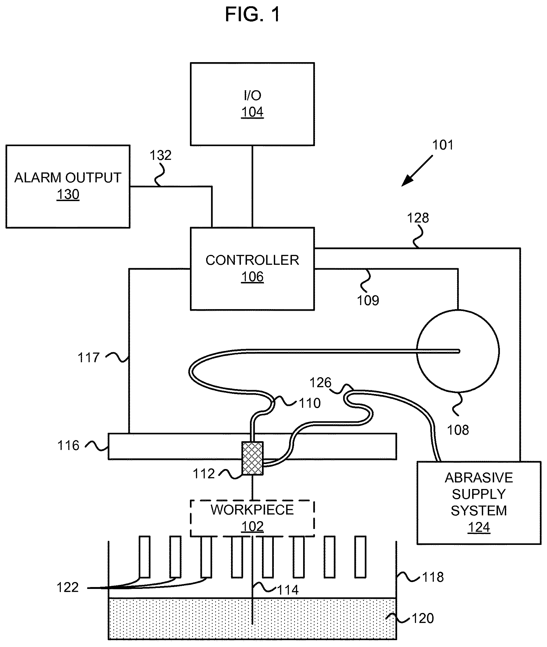
FIG. 1 is a diagram of an abrasive fluid jet system, according to an embodiment.
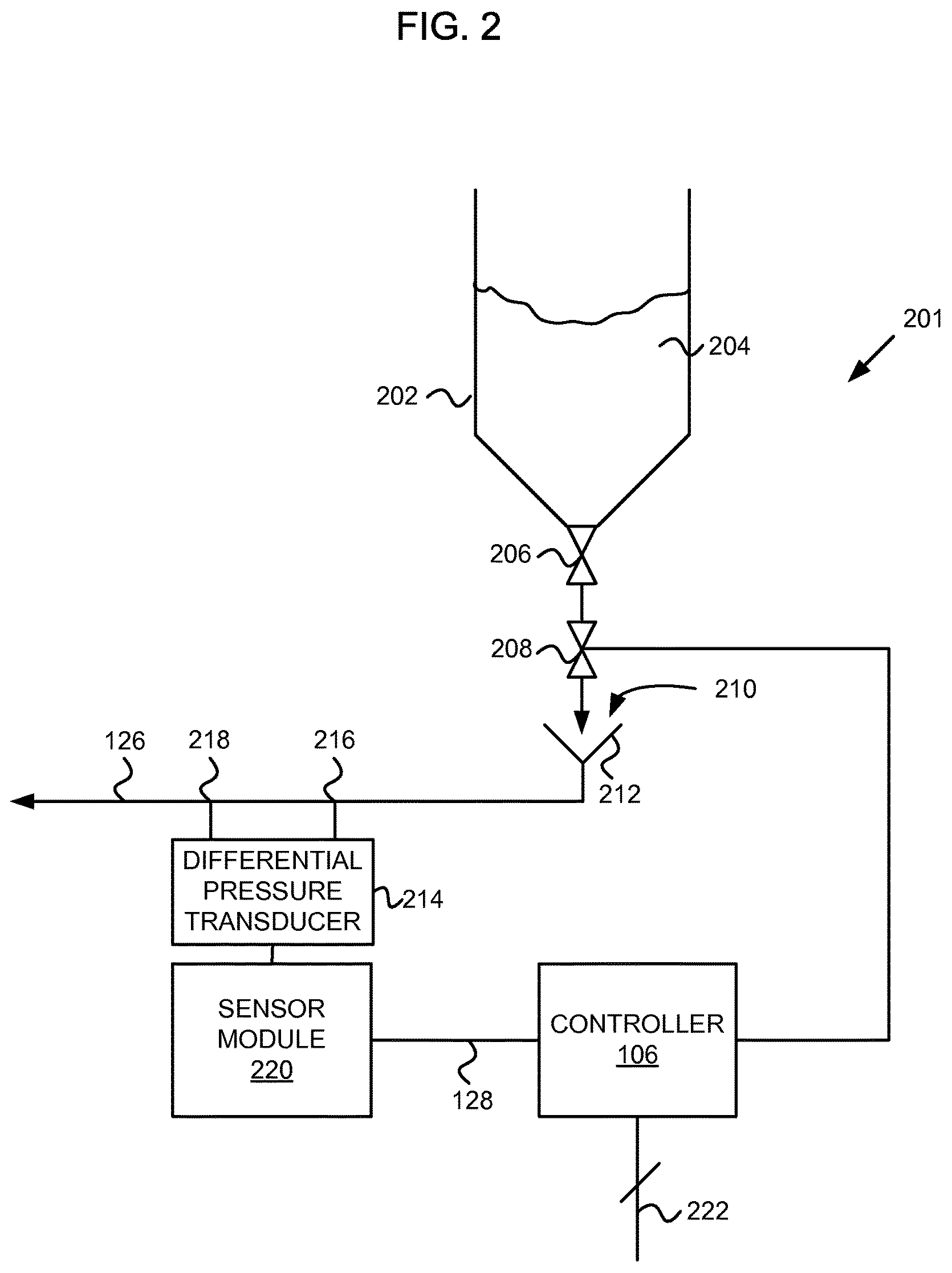
FIG. 2 is a diagram showing a relationship between the abrasive supply system and controller of FIG. 1, according to an embodiment.
FIG. 3 is a diagram of a portion of the abrasive delivery tube of FIGS. 1 and 2 including a fitting with differential pressure measurement points, according to an embodiment.
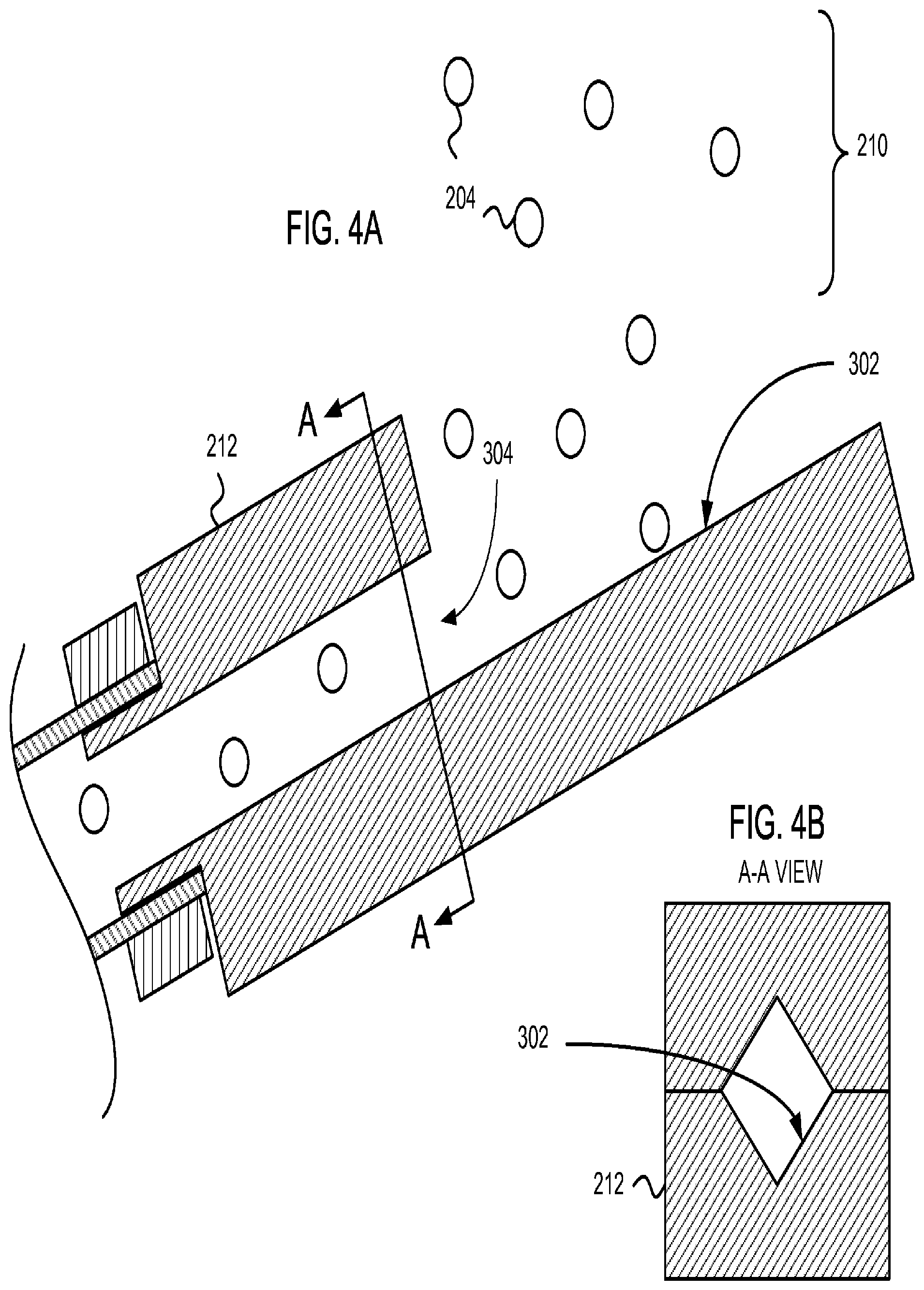
FIG. 4A is a side sectional view of an abrasive inlet port, according to an embodiment.
FIG. 4B is a cross-sectional view of the abrasive inlet port of FIG. 4A, according to an embodiment.
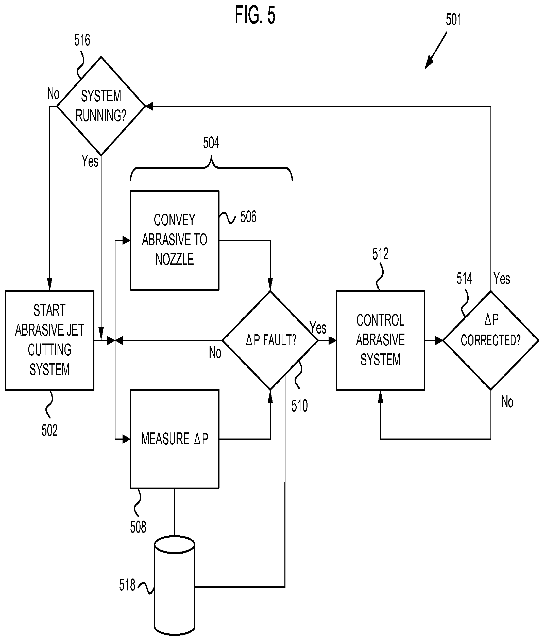
FIG. 5 is a flow chart illustrating operation of an abrasive jet cutting system with a differential pressure abrasive flow measurement, according to an embodiment.
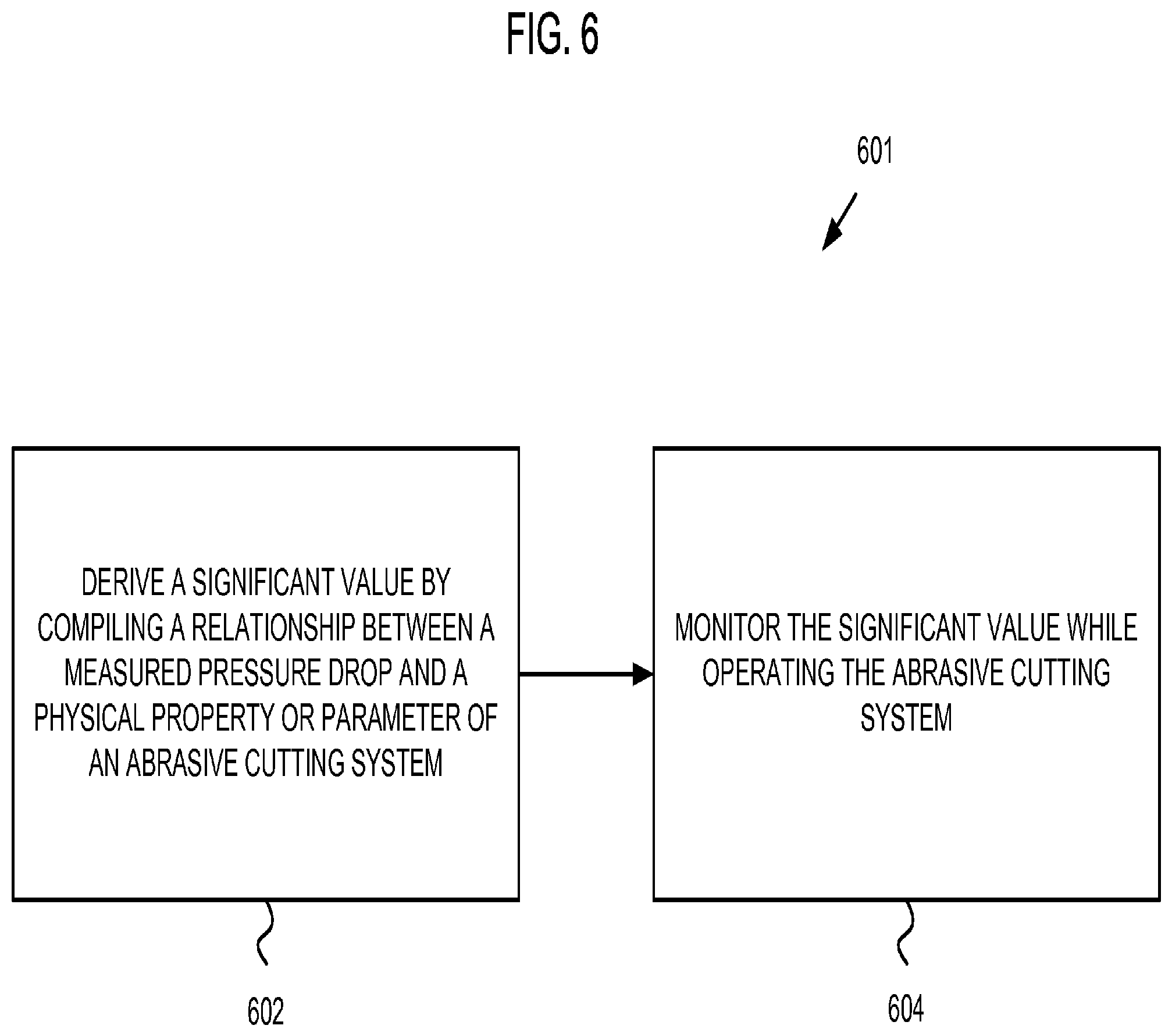
FIG. 6 is a flow chart showing a method 601 for monitoring an abrasive entrainment fluid jet, according to an embodiment.
DETAILED DESCRIPTION
In the following detailed description, reference is made to the accompanying drawings, which form a part hereof. In the drawings, similar symbols typically identify similar components, unless context dictates otherwise. The illustrative embodiments described in the detailed description, drawings, and claims are not meant to be limiting. Other embodiments may be utilized, and other changes may be made, without departing from the spirit or scope of the subject matter presented here.
FIG. 1 is a diagram illustrating a fluid jet cutting system 101 configured to cut a workpiece 102, according to an embodiment. A computer interface 104 may be configured to receive computer instructions corresponding to a cutting path through the workpiece 102. A controller 106 may be configured to receive the computer instructions to drive the fluid jet cutting system 101. Alternatively, the cutting path may be produced by nozzle motion and/or workpiece motion driven by a different method, such as by hand guiding, for example.
The controller 106 may be operatively coupled to a high pressure pump 108 via a pump interface 109. The pump 108 may optionally be controlled separately. The high pressure fluid pump 108 is configured to provide high pressure fluid through high pressure tubing 110 to a nozzle 112. The nozzle 112 receives the high pressure fluid and projects a high velocity fluid cutting jet 114.
The controller 106 is operatively coupled to drive an actuation system 116 configured to drive the position of the nozzle 112 via an actuation interface 117. Typically actuation systems 116 include at least X-Y drive. Some actuation systems additionally include Z-axis and tilting axes. The controller 106 drives the actuation system 116 to position the nozzle 112 to scan the fluid jet 114 across the workpiece 102 to make cuts. The workpiece 102 can be supported by a workpiece support system 118 including bed slats 122 over a pool of water 120. Other embodiments can include a fixed cutting head with an actuated workpiece.
A particle supply system 124 may provide abrasive particles such as garnet entrained in air to the nozzle 112 through abrasive particle supply tube 126, and particularly to a mixing tube (not shown). At the mixing tube, the high velocity jet 114 draws a partial vacuum at an outlet port of the abrasive supply tube 126, which creates a pneumatic driving force to drive particles through the abrasive particle supply tube 126. The high velocity jet entrains the air containing the abrasive particles. The abrasive supply system 124 (of which the abrasive supply tube 126 may generally be considered to be a part) includes at least one signal transmission path 128 configured to couple the abrasive supply system 124 to the controller 106. The signal transmission path 128 may be configured to transmit a differential pressure signal from the abrasive supply system 124 to the controller 106.
An optional alarm output 130 may provide an apparatus for alerting a user of one or more operating and/or fault conditions. For example, the alarm output 130 may include a bell, speaker, beeper, buzzer, or other audible output selected to call attention to a fault condition. Alternatively or additionally, the alarm output 130 may include a visible indicator such as a computer display, a gauge, an indicator light, a strobe light or other visible output selected to call attention to a fault condition. The alarm output 130 may also generate or cause to be generated a display or transmission of an electronic message to call attention to a fault condition. The controller 106 may be configured to provide an alarm signal to the alarm output 130 via a signal transmission path 132. Optionally, the interface 104 may provide an interface to an alarm output 130 and a separate signal transmission path 132 may be omitted.
FIG. 2 is a block diagram of a subsystem 201 showing a relationship between components of the abrasive supply system 124 and controller 106 of FIG. 1, according to an embodiment. An abrasive hopper 202 may hold abrasive particles 204. The abrasive hopper 202 may, for example, be held substantially at atmospheric pressure, or alternatively may be held under vacuum or at an elevated pressure. Abrasive particles 204 are metered from the abrasive hopper 202 through a metering apparatus or valve 206 that controls the rate of flow. According to an embodiment, the metering apparatus or valve 206 may be a predetermined length of tube at a predetermined diameter that allows a relatively constant rate of abrasive flow; using an effect similar to the neck of an hourglass. Optionally, the metering apparatus or valve 206 may be controlled by the controller 106 through a signal interface (not shown).
The abrasive particles may next flow through an optional shut-off valve 208 that is optionally actuated by the controller 106. According to an embodiment, the abrasive particles 204 fall from the metering apparatus or valve 206 and the optional shut-off valve 208 under gravity through an optional air gap 210 and into an abrasive inlet port 212 that is operatively coupled to the abrasive supply tube 126. An embodiment of the abrasive inlet port 212 is shown in more representative form in FIGS. 4A and 4B.
In alternative embodiments, the abrasive particles 204 may be pulled from the abrasive hopper 202 under gravity, responsive to a screw conveyor, vacuum, pressure, or other abrasive introduction mechanism corresponding to the apparatus 206, 208, 212 between from the abrasive hopper 202 and the abrasive supply tube 126. The controller 106 may control such alternative apparatuses responsive to the measurement of differential pneumatic pressure described herein.
According to an embodiment, the metering apparatus or valve 206 can include a mechanism such as a variable aperture to constrain the passage of abrasive particles. For example, the metering apparatus or valve 206 may include a slide (not shown) configured to vary the size of a gap through which abrasive particles 204 are metered. The shut-off valve 208 may be also be embodied as a slide valve, or may be embodied as a bladder valve, for example. Optionally, the shut off valve 208 may be omitted and on/off functionality may be provided by the metering apparatus or valve 206.
After entering the abrasive supply tube 126 at the abrasive inlet port 212, the abrasive particles are entrained in air moving through the abrasive supply tube 126 and are pneumatically conveyed as entrained particles through the abrasive supply tube 126 to an abrasive outlet port (not shown) that opens into a nozzle mixing tube (not shown).
The air moving through the abrasive particle supply tube 126 moves faster than the particles entrained in the air. This "blows" the particles through the abrasive supply tube 126. Typically, frictional effects of the air moving past and around the abrasive particles causes a pressure drop. A larger amount or concentration of abrasive particles in the abrasive particle supply tube 126 causes a higher pneumatic pressure loss. Thus, the pressure drop through the abrasive supply tube 126 is indicative of the flowing condition and flow rate of the entrained particles.
The pneumatic pressure loss in the abrasive supply tube 126 is measured as a differential pressure between at least two points 216 and 218 along the abrasive supply tube 126. The first point 216 may correspond to a first orifice and the second point 218 may correspond to a second orifice located along the abrasive supply tube 126 between and not including the inlet port 212 or the abrasive outlet port (not shown). According to an embodiment, the first point 216 and the second point 218 may be located along a fitting, as shown below.
A differential pressure transducer 214 is configured to measure the differential pressure between the first 216 and second 218 orifices. Optionally, the differential pressure between the first 216 and second orifices 218 may be measured by a respective first transducer and second transducer (not shown) that each measure an absolute or gauge pressure. The respective absolute or gauge pressures may be converted to a differential pressure by pressure comparison.
In some applications the distance between differential measurement points 216, 218 may be relatively small. According to an embodiment, the measured differential pressure may be substantially attributable to pressure drop created by air flow around entrained abrasive particles. In other applications, the distance between differential measurement points 216, 218 may be large and/or there may be an ell or another fitting between the measurement points 216, 218. According to an embodiment, the differential pressure may correspond to friction losses substantially created by a combination of airflow between the at least two points and airflow around the entrained abrasive particles between the at least two points.
Optionally, a sensor module 220 may receive the differential pressure electrical signal and convert it to data that is transmitted to the controller 106 via the at least one signal transmission path 128. Alternatively, the sensor module 220 may receive first and second absolute or gauge pressure transducer electrical signals and convert them to a differential pressure signal or data that is then transmitted to the controller 106. The differential pressure signal may include a signal and/or data transmitted between the sensor module 220 and the controller 106.
According to an embodiment, the pressure transducer 214 and the sensor module 220 (or optionally an integrated portion of the controller 106) may further be configured to sense an absolute or average gauge pressure in addition to sensing a differential pressure.
The controller 106 may be configured to transmit one or more signals through one or more interfaces 222 responsive to the pressure differential between points 216 and 218. For example the one or more interfaces 222 may include the pump interface 109, the actuation interface 117, the signal transmission path 132 that interfaces with the alarm output 130, or the interface 104 shown in FIG. 1. Thus, the controller 106 may be configured to receive a differential pressure signal from the abrasive supply system 124 and responsively control the supply of fluid to the high pressure nozzle 112, movement of the actuation system 116 for the high pressure nozzle 112, operation of the abrasive supply system 124, providing an alarm from the alarm output 130, and/or other responses or actions.
When the system or subsystem 101, 201 is starting up, differential pressure between points 216, 218 may typically be quite low or otherwise outside a normal operating range. The controller 106 may be configured to ignore the differential pressure during start-up.
During operation, the controller 106 may be configured to respond when the differential pressure signal indicates a decrease in differential pressure below a predetermined value. According to an embodiment, the predetermined value may be determined at least in part responsive to a previously measured differential pressure. For example, changes arising from variations in abrasive particle size, system wear, and other factors may be exhibited and monitored as gradual changes in differential pressure that do not relate to fault conditions. Such gradual changes may be tracked and used to monitor the system condition until a value is reached which may result in a state at which the controller 106 responds with a fault response.
Optionally, the controller 106 may operate at least partially using digital logic, analog logic, and/or fluid logic. In the case of at least a portion of the controller 106 including a fluid logic, the differential pressure transducer 214 (or alternatively the pair of absolute or gauge pressure transducers, not shown) may be omitted and the differential pressure signal transmission path and/or the at least one signal transmission path 128 may include pneumatic or vacuum lines rather than electrical conduction paths, wireless signal transmission paths, etc. In the case of a controller 106 that is at least partially pneumatic, the differential pressure transducer 214 may be replaced by one or more diaphragms or filters configured to separate a "clean" pneumatic controller side from a "dirty" pneumatic conveying gas in the abrasive supply tube 126.
FIG. 3 is a side sectional view of a portion 301 of the abrasive supply tube 126 of FIGS. 1 and 2 including the differential pressure points 216, 218, according to an embodiment. The abrasive supply tube 126 may include a fitting 302. The fitting 302 may be referred to as a differential pressure measurement fitting.
The fitting 302 includes walls that define a flow channel 304, having a diameter D, configured to provide a path for the flow of gas with entrained abrasive from a flow channel input 306 to a flow channel output 308. First and second pressure measurement ports 310, 314 may be configured to receive a differential pressure measurement transducer 214 (or alternatively, respective absolute or gauge pressure transducers) shown in block diagram form in FIG. 2. Alternatively or additionally, the pressure measurement ports 310, 314 may be configured to receive pneumatic diaphragms, filters, and/or fittings for coupling to pneumatic signal lines. The first and second measurement ports 310, 314 communicate with the flow channel 304 via respective orifices 312, 316.
At the entrance 306 to the flow channel 304, the fitting 302 includes a first coupling 318 configured couple the abrasive flow channel 304 to receive air-entrained abrasive from an abrasive source, such as the abrasive supply system 124. At the exit 308 from the flow channel 304, the fitting 302 includes a second coupling 320 configured couple the abrasive flow channel to the rest of the abrasive supply tube 126. According to an embodiment, the first pressure measurement point 216 and corresponding orifice 312 are situated at a position far enough away from the input 306 to avoid perturbations in gas and abrasive flow arising from entrance effects.
The first and second orifices 312, 316 are arranged at different positions along the length of the flow channel 304 separated by a distance L. According to an embodiment, the orifices 312, 316 of the pressure measurement ports 310, 314 are configured to have similar or substantially identical flow restriction. The substantially identical flow restriction may provide substantially identical entrance pressure losses for the respective orifices 312, 316.
The differential pressure measured between the pressure measurement ports 310 and 314 correlates with the amount (e.g., the concentration) of particles entrained between the pressure measurement ports 310, 314. The pressure drop is caused by a summation of frictional losses as air flows around each particle. For a system that is operating normally, the number of abrasive particles entrained between the pressure measurement ports 310, 314 at any one time remains substantially constant. Thus, the differential pressure is indicative of the pneumatic air flow condition (e.g., the velocity of air) and the concentration of abrasive particles in the control volume between the measurement ports. It is therefore a measure of the condition of the airstream and the condition of abrasive particle delivery to the nozzle, which may also be indicative of the abrasive flow rate and the condition of the air flow producing venturi system in the cutting head.
Notably, the fitting 302 does not include a conventional pressure drop constriction such as a metering plate or a venturi. In such systems, the pressure drop is a function of the (fixed) geometry of a flow constriction disposed between differential pressure measurement ports. Conventional differential pressure measurement fittings, for example that include a plate with a hole or a venturi through which gas flows, have a fixed geometry and hence a fixed pressure drop. However, such conventional measurement fittings are not suitable to measuring flow of a gas carrying entrained particles because the particles can cause excessive wear on the fitting. In place of a flow constriction such as a plate or venturi, embodiments of the present invention use the presence of the particles themselves to create a restriction for measuring the differential pressure. The gas (air) generally moves significantly faster than the particles. Thus, each particle can be modeled as a stationary sphere with gas moving around it.
Optionally, absolute or gauge pressure may also be measured. Absolute or gauge pressure may be measured as the pressure at one or the other of the points 216, 218. Average (absolute or gauge) pressure may be measured by averaging the pressures measured at both points 216, 218.
FIG. 4A is a side sectional view of an abrasive particle inlet port 212, according to an embodiment. FIG. 4B is a cross-sectional view of the abrasive inlet port of FIG. 4A, according to an embodiment. With reference to FIG. 2 and FIGS. 4A and 4B, the abrasive particles 204 fall through the air gap 210 onto a collection surface 302 of the inlet port 212. According to an embodiment, the collection surface 302 is a V-shaped extension of the inlet port 212 and is sized to collect much or all of the falling abrasive particles 204. As shown, the collection surface 302 may be held at an angle selected to deflect the abrasive particles 204 toward an inlet port entrance 304. Vacuum produced at the mixing tube (not shown) draws air into the inlet port entrance 304. The inrush of air entrains abrasive particles 204 and also pulls the abrasive particles into the inlet port entrance 304.
The controller 106 may respond to changes in the differential pressure LIP in various ways, according to embodiments. FIG. 5 is a flow chart 501 illustrating operation embodiment of an abrasive jet cutting system depicted in the illustrative embodiments of FIGS. 1 and 2. Beginning at step 502, the abrasive jet cutting system, including at least the pump 108 and the abrasive supply system 124, is started. During step 502, a non-steady state may exist in abrasive flow. The differential pressure may therefore fluctuate as steady state abrasive flow is established. During step 502, the controller 106 may ignore the differential pressure .DELTA.P or alternatively apply different set points and/or logic that determine how to respond to changes in differential pressure .DELTA.P.
When start-up 502 is complete, the system progresses to an operation state 504. During the operation state 504, step 506 progresses, wherein abrasive is conveyed to the nozzle 112 through the abrasive supply tube 126. Simultaneously, one or more pumps 108 are operated to provide high pressure fluid to the nozzle 112. The nozzle 112 includes a mixing tube (not shown). The high velocity movement of the fluid jet 114 produces a partial vacuum in the mixing tube. The partial vacuum in the mixing tube (where the output port of the abrasive supply tube 126 is located) creates a pressure differential driving force sufficient to pneumatically convey the abrasive particles from the abrasive input port to the abrasive output port. The abrasive particles become entrained in the high velocity jet 114 in the mixing tube (not shown). Optionally, step 506 may include opening a valve or operating a compressor to provide abrasive conveying air.
In one embodiment, a pressure drop may be detected in step 508 in a state wherein abrasive is not flowing. This detection of the pressure drop may provide information about the condition of the high velocity jet 114 without abrasives, which is information that can be useful to monitor regularly.
Substantially simultaneously in a state wherein abrasive is flowing in step 506, step 508 progresses where the differential pressure .DELTA.P is measured as described elsewhere herein. Optionally, differential pressure .DELTA.P measurement may be accompanied by an average, absolute, or gauge pressure measurement, which may provide additional information about operation of the system, as described above. Proceeding to step 510, the measured differential pressure .DELTA.P is compared to a set point or a range, and the existence or absence of a differential pressure .DELTA.P fault is determined. Optionally, step 510 may also include determination of the existence or absence of an absolute, gauge, or average pressure fault.
As described above, the differential pressure .DELTA.P decreases in response to or when the velocity V decreases corresponding to a reduction in gas flow. Similarly the differential pressure .DELTA.P decreases in response to or when the (variable) coefficient of friction decreases corresponding to a reduction of abrasive in the gas.
If no differential pressure fault exists, the program returns to continue executing steps 506 and 508. The process 504 may continue substantially continuously while the system operates. The method or program 501 may, within the process 504, execute an explicit step 510 at an interval, or may alternatively operate according to interrupt logic. According to embodiments, the process 504 may be at least partly embodied by or in software executed by a processor (such as by the controller 106 or other processor), firmware, and/or hardware.
If a pressure fault is determined to exist in step 510, the program proceeds to step 512 where the system is controlled responsive to the pressure fault. Step 512 may include correction of a problem, and/or may represent providing an alert and/or shutting down at least portions of the abrasive jet cutting system. For example, controlling operation of the abrasive fluid jet cutting system 101 may include at least one of controlling the pump 108 (e.g., shutting off the pump), controlling an abrasive supply system (e.g., stopping the flow of gas to the abrasive supply system or refilling the abrasive hopper 202), controlling the actuation system 116 of the nozzle 112 (e.g., by moving the nozzle 112 to a safe position such as to reduce the possibility of damage to a workpiece 102), and/or controlling an alarm (e.g. outputting an alarm signal via an alarm output 130 to alert a user of the fault condition).
If the differential pressure .DELTA.P fault is corrected, as determined by step 514, the process proceeds to step 516. Step 516 is a decision block that determines whether or not the system is running. For example step 512 may involve refilling the abrasive hopper, modifying an abrasive gas pressure, modifying cutting parameters, or other response that does not involve shutting down the abrasive jet cutting system 101. In the case where the response to the differential pressure fault involves such corrective or adaptive actions, the program 501 may return to the process 504 where operation may continue substantially unimpeded. Alternatively, the system control provided in step 512 may involve shutting down all or a portion of the abrasive jet cutting system 101. If the system is at least partially shut down, the program 501 may proceed from step 516 to step 502, where the system is started up again.
Optionally, step 508 may include writing differential pressure .DELTA.P values, or one or more parameters calculated therefrom, to differential pressure data storage 518. The algorithm to determine the existence of a differential pressure fault used by step 510 may read the differential pressure .DELTA.P values or parameters in the differential pressure data storage 518 to determine the existence or absence of a differential pressure .DELTA.P fault. Values from the differential pressure data storage 518 may be used to determine a differential pressure .DELTA.P set point at which a fault is considered to exist. For example, a progression of smoothly increasing or decreasing differential pressure .DELTA.P values may be attributed to normal wear, a gradual depletion of abrasive particles in a hopper, a change in abrasive grit, or other effects, and the differential pressure fault set point parameter may be modified in the differential pressure data storage 518 to accommodate such normal variations in operating characteristics.
Values from the differential pressure data storage 518 may additionally or alternatively be used to select from among possible control algorithms performed in step 512. For example, a differential pressure .DELTA.P history and/or absolute, gauge, or average pressure history stored in the differential pressure data storage 518 may be used to illuminate the nature of a differential pressure fault. For example, a gradual change in differential pressure .DELTA.P may be indicative of a reduced abrasive flowrate, and a control algorithm executed in step 512 may involve simply alerting a user of a need to adjust the settings for the abrasive flowrate. Alternatively, an abrupt change in differential pressure .DELTA.P may be indicative of a serious malfunction and drive a control algorithm executed in step 512 to perform a system shutdown.
Additionally, the algorithm performed during process 504 may be augmented by information related to other operating parameters of the system. For example, a system shutdown or modification may be delayed until after completion of a cut or a workpiece.
FIG. 6 is a flow chart showing a method 601 for monitoring an abrasive entrainment fluid jet, according to an embodiment. In step 602, a significant value may be derived by compiling a relationship between a measured pressure drop in an abrasive particle delivery subsystem and at least one physical property or parameter of an abrasive cutting system. For example, deriving the significant value may include compiling a relationship between the measured pressure drop and an abrasive cutting system water pressure. In another example, optionally used in a multivariate relationship along with water pressure, deriving the significant value may include compiling a relationship between the measured pressure drop and an abrasive cutting system orifice diameter or mixing tube diameter.
Proceeding to step 604, the significant value may be monitored while operating the abrasive cutting system 101. Monitoring the significant value may include comparing the significant value with one or more pre-determined constant values to determine the condition of air flow in the abrasive particle subsystem. Such an approach may be applied dynamically. For example, monitoring the significant value while operating the abrasive cutting system may include comparing the significant value with one or more predetermined constant values to determine the condition and changes of the water jet. Additionally or alternatively, monitoring the significant value while operating the abrasive cutting system 101 may include comparing the significant value with the one or more predetermined constant values to determine the condition and changes in abrasive flow rate. For example, this may include comparing the significant value with the one or more predetermined constant values to determine a flow rate of abrasive particles being carried by the entraining air.
The method 601 may also include a step of predetermining constant values for comparison (not shown). The predetermined constant values may be determined in a variety of ways. For example, the method 601 may include determining the one or more predetermined constant values by measuring the significant value at fixed conditions while the abrasive cutting system is operating properly. This can provide a baseline against which the significant value is compared. Alternatively, the predetermined constant value may be calculated from physical properties and parameters of the abrasive cutting system. Similarly, the predetermined constant value may be determined by a combination of calculation from physical properties and parameters of the abrasive cutting system and by measuring the significant value at fixed conditions while the abrasive cutting system is operating properly.
A variety of additional steps may be performed responsive to the monitoring 604. For example, the method 601 may include displaying the monitored significant value and/or a predetermined reference value (not shown). Moreover, the method 601 may include generating a statistical value corresponding to variations in the monitored significant value (not shown). The method 601 may also include analyzing the performance of the abrasive cutting system by comparing monitored significant values or the statistical value corresponding to variations in the monitored significant value against predetermined significant values.
Optionally, the analysis is performed by an abrasive fluid jet controller, such as the controller 106 shown in FIG. 1. Alternatively, the analysis may performed by a computer operatively coupled to the abrasive fluid jet controller via the data interface 104 (FIG. 1). The method 601 may also include actuating an alarm output (not shown) in response to or when the monitored significant value changes by an amount corresponding to an alarm. the alarm may be output via the data interface 104 and/or via an alarm 130 and/or via an alarm signal transmission path 132 (FIG. 1), including electronic messages like email, SMS, and the like.
Optionally, the method 601 may include pausing the abrasive fluid jet cutter at a next convenient point or immediately stopping the abrasive fluid jet cutter (not shown) in response to or when the monitored significant value changes by a corresponding amount.
While the transmission of signals and actions has been described as positive signal transmission, other forms of data or signal transmission may be substituted. For example, referring to FIG. 2, the interface between the sensor module 220 and the controller 106 may be configured as a fail-safe interface where stopping the transmission of data or a signal corresponds to a fault condition. Referring to FIG. 1, similar interfaces may be provided between the controller 106 and other system components such as the pump interface 109, the actuation interface 117 and/or the signal transmission path 132 that interfaces with the alarm output 130 and may involve positive or negative data or signal conditions. Accordingly, transmitting a signal may include sending a signal or ceasing to send a signal.
Although the embodiments described herein may refer with some amount of specificity to an abrasive supply system for an abrasive jet cutting system, the differential pressure measurement method (including a differential pressure measurement fitting that includes no fixed pressure drop constriction) may be applied to the measurement of flow in other pneumatic particle conveyors. For example, solids material handling systems such as used in the cement and concrete industries, food production, and other industries may benefit from the flow measurement described herein.
The descriptions and figures presented herein are necessarily simplified to foster ease of understanding. Other embodiments and approaches may be within the scope of embodiments described herein. Embodiments described herein shall be limited only according to the appended claims, which shall be accorded their broadest valid meaning.
* * * * *
References
D00000
D00001
D00002
D00003
D00004
D00005
D00006
XML
uspto.report is an independent third-party trademark research tool that is not affiliated, endorsed, or sponsored by the United States Patent and Trademark Office (USPTO) or any other governmental organization. The information provided by uspto.report is based on publicly available data at the time of writing and is intended for informational purposes only.
While we strive to provide accurate and up-to-date information, we do not guarantee the accuracy, completeness, reliability, or suitability of the information displayed on this site. The use of this site is at your own risk. Any reliance you place on such information is therefore strictly at your own risk.
All official trademark data, including owner information, should be verified by visiting the official USPTO website at www.uspto.gov. This site is not intended to replace professional legal advice and should not be used as a substitute for consulting with a legal professional who is knowledgeable about trademark law.