Method and system of connecting to a multipath hub in a cluster
Mayya , et al. Sept
U.S. patent number 10,778,528 [Application Number 15/707,124] was granted by the patent office on 2020-09-15 for method and system of connecting to a multipath hub in a cluster. This patent grant is currently assigned to NICIRA, INC.. The grantee listed for this patent is Nicira, Inc.. Invention is credited to Nitin Kumar Ananda, Stephen Craig Connors, Ajit Ramachandra Mayya, Sunil Mukundan, Parag Pritam Thakore, Steven Michael Woo.


| United States Patent | 10,778,528 |
| Mayya , et al. | September 15, 2020 |
Method and system of connecting to a multipath hub in a cluster
Abstract
In one aspect, a computerized method useful for connecting to a multipath hub in a cluster includes the step of, with a gateway in a same network as the cluster, receiving, from a branch edge, a request to connect to a logical identifier (ID) of the multipath hub. The gateway recognizes a logical ID representing a cluster. The gateway determines a least-loaded edge in the cluster to be the multipath hub. The gateway returns a connectivity information for the multipath hub. The branch edge configures a tunnel to the multipath hub.
| Inventors: | Mayya; Ajit Ramachandra (Saratoga, CA), Thakore; Parag Pritam (Los Gatos, CA), Connors; Stephen Craig (San Jose, CA), Woo; Steven Michael (Los Altos, CA), Mukundan; Sunil (Chennai, IN), Ananda; Nitin Kumar (San Jose, CA) | ||||||||||
|---|---|---|---|---|---|---|---|---|---|---|---|
| Applicant: |
|
||||||||||
| Assignee: | NICIRA, INC. (Palo Alto,
CA) |
||||||||||
| Family ID: | 1000005057299 | ||||||||||
| Appl. No.: | 15/707,124 | ||||||||||
| Filed: | September 18, 2017 |
Prior Publication Data
| Document Identifier | Publication Date | |
|---|---|---|
| US 20180234300 A1 | Aug 16, 2018 | |
Related U.S. Patent Documents
| Application Number | Filing Date | Patent Number | Issue Date | ||
|---|---|---|---|---|---|
| 62523477 | Jun 22, 2017 | ||||
| 62457816 | Feb 11, 2017 | ||||
| Current U.S. Class: | 1/1 |
| Current CPC Class: | H04L 43/0811 (20130101); H04L 41/12 (20130101); H04L 12/4633 (20130101); H04L 43/0876 (20130101); H04L 41/0803 (20130101); H04L 47/125 (20130101); H04L 63/029 (20130101); H04L 63/0272 (20130101) |
| Current International Class: | H04L 12/24 (20060101); H04L 29/06 (20060101); H04L 12/46 (20060101); H04L 12/26 (20060101); H04L 12/803 (20130101) |
References Cited [Referenced By]
U.S. Patent Documents
| 6154465 | November 2000 | Pickett |
| 6445682 | September 2002 | Weitz |
| 7003481 | February 2006 | Banka et al. |
| 7320017 | January 2008 | Kurapati et al. |
| 7680925 | March 2010 | Sathyanarayana et al. |
| 7962458 | June 2011 | Holenstein et al. |
| 8111692 | February 2012 | Ray |
| 8224971 | July 2012 | Miller et al. |
| 8228928 | July 2012 | Parandekar et al. |
| 8243589 | August 2012 | Trost et al. |
| 8259566 | September 2012 | Chen et al. |
| 8566452 | October 2013 | Goodwin, III et al. |
| 8724456 | May 2014 | Hong et al. |
| 8964548 | February 2015 | Keralapura et al. |
| 9055000 | June 2015 | Ghosh et al. |
| 9071607 | June 2015 | Twitchell, Jr. |
| 9075771 | July 2015 | Gawali et al. |
| 9154327 | October 2015 | Marino et al. |
| 9306949 | April 2016 | Richard et al. |
| 9336040 | May 2016 | Dong et al. |
| 9354983 | May 2016 | Yenamandra et al. |
| 9432245 | August 2016 | Sorenson, III |
| 9450817 | September 2016 | Bahadur et al. |
| 9450852 | September 2016 | Chen et al. |
| 9462010 | October 2016 | Stevenson |
| 9525564 | December 2016 | Lee |
| 9608962 | March 2017 | Chang |
| 9665432 | May 2017 | Kruse et al. |
| 9686127 | June 2017 | Ramachandran et al. |
| 9715401 | July 2017 | Devine et al. |
| 9722815 | August 2017 | Mukundan et al. |
| 9787559 | October 2017 | Schroeder |
| 9825822 | November 2017 | Holland |
| 9906401 | February 2018 | Rao |
| 10057183 | August 2018 | Salle et al. |
| 10135789 | November 2018 | Mayya et al. |
| 10178032 | January 2019 | Freitas |
| 10187289 | January 2019 | Chen |
| 10229017 | March 2019 | Zou et al. |
| 10237123 | March 2019 | Dubey et al. |
| 10320664 | June 2019 | Nainar et al. |
| 10326830 | June 2019 | Singh |
| 10348767 | July 2019 | Lee et al. |
| 2002/0198840 | December 2002 | Banka et al. |
| 2003/0088697 | May 2003 | Matsuhira |
| 2003/0112808 | June 2003 | Solomon |
| 2003/0126468 | July 2003 | Markham |
| 2003/0161313 | August 2003 | Jinmei et al. |
| 2003/0202506 | October 2003 | Perkins et al. |
| 2003/0219030 | November 2003 | Gubbi |
| 2004/0059831 | March 2004 | Chu et al. |
| 2004/0068668 | April 2004 | Lor et al. |
| 2004/0224771 | November 2004 | Chen et al. |
| 2005/0078690 | April 2005 | DeLangis |
| 2006/0114838 | June 2006 | Mandavilli et al. |
| 2006/0171365 | August 2006 | Borella |
| 2006/0182034 | August 2006 | Klinker et al. |
| 2006/0193247 | August 2006 | Naseh et al. |
| 2007/0064604 | March 2007 | Chen et al. |
| 2007/0091794 | April 2007 | Filsfils et al. |
| 2007/0121486 | May 2007 | Guichard et al. |
| 2007/0177511 | August 2007 | Das et al. |
| 2007/0260746 | November 2007 | Mirtorabi et al. |
| 2008/0049621 | February 2008 | McGuire et al. |
| 2008/0080509 | April 2008 | Khanna et al. |
| 2008/0095187 | April 2008 | Jung et al. |
| 2008/0219276 | September 2008 | Shah et al. |
| 2009/0125617 | May 2009 | Klessig et al. |
| 2009/0154463 | June 2009 | Hines et al. |
| 2009/0247204 | October 2009 | Sennett et al. |
| 2010/0008361 | January 2010 | Guichard et al. |
| 2010/0088440 | April 2010 | Banks et al. |
| 2010/0118727 | May 2010 | Draves et al. |
| 2010/0191884 | July 2010 | Holenstein et al. |
| 2010/0332657 | December 2010 | Elyashev |
| 2011/0040814 | February 2011 | Higgins |
| 2011/0075674 | March 2011 | Li et al. |
| 2011/0110370 | May 2011 | Moreno et al. |
| 2011/0153909 | June 2011 | Dong |
| 2012/0008630 | January 2012 | Ould-Brahim |
| 2012/0027013 | February 2012 | Napierala |
| 2012/0157068 | June 2012 | Eichen et al. |
| 2012/0173919 | July 2012 | Patel et al. |
| 2012/0221955 | August 2012 | Raleigh et al. |
| 2012/0250682 | October 2012 | Vincent et al. |
| 2012/0250686 | October 2012 | Vincent et al. |
| 2012/0300615 | November 2012 | Kempf et al. |
| 2012/0317291 | December 2012 | Wolfe |
| 2013/0019005 | January 2013 | Hui et al. |
| 2013/0021968 | January 2013 | Reznik et al. |
| 2013/0044764 | February 2013 | Casado |
| 2013/0051399 | February 2013 | Zhang |
| 2013/0103834 | April 2013 | Dzerve et al. |
| 2013/0124718 | May 2013 | Griffith et al. |
| 2013/0124911 | May 2013 | Griffith et al. |
| 2013/0124912 | May 2013 | Griffith et al. |
| 2013/0128889 | May 2013 | Mathur et al. |
| 2013/0142201 | June 2013 | Kim et al. |
| 2013/0173788 | July 2013 | Song |
| 2013/0182712 | July 2013 | Aguayo et al. |
| 2013/0238782 | September 2013 | Zhao et al. |
| 2013/0242718 | September 2013 | Zhang |
| 2013/0254599 | September 2013 | Katkar et al. |
| 2013/0258839 | October 2013 | Wang et al. |
| 2013/0283364 | October 2013 | Chang et al. |
| 2013/0301642 | November 2013 | Radhakrishnan et al. |
| 2013/0329548 | December 2013 | Nakil et al. |
| 2014/0019604 | January 2014 | Twitchell, Jr. |
| 2014/0092907 | April 2014 | Sridhar et al. |
| 2014/0108665 | April 2014 | Arora et al. |
| 2014/0112171 | April 2014 | Pasdar |
| 2014/0156818 | June 2014 | Hunt |
| 2014/0156823 | June 2014 | Liu et al. |
| 2014/0173113 | June 2014 | Vemuri et al. |
| 2014/0173331 | June 2014 | Martin et al. |
| 2014/0219135 | August 2014 | Li et al. |
| 2014/0223507 | August 2014 | Xu |
| 2014/0244851 | August 2014 | Lee |
| 2014/0258535 | September 2014 | Zhang |
| 2014/0317440 | October 2014 | Biermayr et al. |
| 2014/0341109 | November 2014 | Cartmell et al. |
| 2015/0016249 | January 2015 | Mukundan et al. |
| 2015/0029864 | January 2015 | Raileanu et al. |
| 2015/0046572 | February 2015 | Cheng et al. |
| 2015/0052247 | February 2015 | Threefoot et al. |
| 2015/0088942 | March 2015 | Shah |
| 2015/0089628 | March 2015 | Lang |
| 2015/0092603 | April 2015 | Aguayo et al. |
| 2015/0096011 | April 2015 | Watt |
| 2015/0146539 | May 2015 | Mehta et al. |
| 2015/0172121 | June 2015 | Farkas et al. |
| 2015/0188823 | July 2015 | Williams |
| 2015/0201036 | July 2015 | Nishiki et al. |
| 2015/0222543 | August 2015 | Song |
| 2015/0236962 | August 2015 | Veres et al. |
| 2015/0271104 | September 2015 | Chikkamath et al. |
| 2015/0334696 | November 2015 | Gu et al. |
| 2015/0350907 | December 2015 | Timariu |
| 2015/0363733 | December 2015 | Brown |
| 2015/0372943 | December 2015 | Hasan et al. |
| 2015/0381493 | December 2015 | Bansal et al. |
| 2016/0035183 | February 2016 | Buchholz et al. |
| 2016/0036924 | February 2016 | Koppolu et al. |
| 2016/0072669 | March 2016 | Saavedra |
| 2016/0105471 | April 2016 | Nunes et al. |
| 2016/0134528 | May 2016 | Lin et al. |
| 2016/0142373 | May 2016 | Ossipov |
| 2016/0164832 | June 2016 | Bellagamba et al. |
| 2016/0164914 | June 2016 | Madhav et al. |
| 2016/0173338 | June 2016 | Wolting |
| 2016/0191363 | June 2016 | Haraszti et al. |
| 2016/0191374 | June 2016 | Singh et al. |
| 2016/0197834 | July 2016 | Luft |
| 2016/0197835 | July 2016 | Luft |
| 2016/0198003 | July 2016 | Luft |
| 2016/0210209 | July 2016 | Verkaik et al. |
| 2016/0218947 | July 2016 | Hughes et al. |
| 2016/0255169 | September 2016 | Kovvuri et al. |
| 2016/0315912 | October 2016 | Mayya et al. |
| 2016/0352588 | December 2016 | Subbarayan et al. |
| 2016/0359738 | December 2016 | Sullenberger et al. |
| 2016/0380886 | December 2016 | Blair et al. |
| 2017/0012870 | January 2017 | Blair et al. |
| 2017/0026283 | January 2017 | Williams et al. |
| 2017/0034129 | February 2017 | Sawant et al. |
| 2017/0053258 | February 2017 | Carney |
| 2017/0055131 | February 2017 | Kong |
| 2017/0064005 | March 2017 | Lee |
| 2017/0093625 | March 2017 | Pera et al. |
| 2017/0118173 | April 2017 | Arramreddy et al. |
| 2017/0123939 | May 2017 | Maheshwari et al. |
| 2017/0126564 | May 2017 | Mayya et al. |
| 2017/0134186 | May 2017 | Mukundan et al. |
| 2017/0163473 | June 2017 | Sadana et al. |
| 2017/0181210 | June 2017 | Nadella et al. |
| 2017/0195169 | July 2017 | Mills et al. |
| 2017/0201585 | July 2017 | Doraiswamy |
| 2017/0207976 | July 2017 | Rovner et al. |
| 2017/0214701 | July 2017 | Hasan |
| 2017/0223117 | August 2017 | Messerli et al. |
| 2017/0237710 | August 2017 | Mayya et al. |
| 2017/0257260 | September 2017 | Govindan et al. |
| 2017/0257309 | September 2017 | Appanna |
| 2017/0264496 | September 2017 | Ao et al. |
| 2017/0279717 | September 2017 | Bethers et al. |
| 2017/0310641 | October 2017 | Jiang et al. |
| 2017/0310691 | October 2017 | Vasseur |
| 2017/0317974 | November 2017 | Masurekar |
| 2017/0337086 | November 2017 | Zhu et al. |
| 2017/0339070 | November 2017 | Chang et al. |
| 2017/0364419 | December 2017 | Lo |
| 2018/0007123 | January 2018 | Cheng et al. |
| 2018/0014051 | January 2018 | Phillips et al. |
| 2018/0034668 | February 2018 | Mayya et al. |
| 2018/0041425 | February 2018 | Zhang |
| 2018/0069924 | March 2018 | Tumuluru et al. |
| 2018/0074909 | March 2018 | Bishop et al. |
| 2018/0077081 | March 2018 | Lauer et al. |
| 2018/0084081 | March 2018 | Kuchibhotla et al. |
| 2018/0131720 | May 2018 | Hobson et al. |
| 2018/0145899 | May 2018 | Rao |
| 2018/0167378 | June 2018 | Kostyukov et al. |
| 2018/0176082 | June 2018 | Katz et al. |
| 2018/0176130 | June 2018 | Banerjee et al. |
| 2018/0213472 | July 2018 | Ishii et al. |
| 2018/0260125 | September 2018 | Botes et al. |
| 2018/0270104 | September 2018 | Zheng et al. |
| 2018/0278541 | September 2018 | Wu |
| 2018/0295529 | October 2018 | Jen et al. |
| 2018/0302286 | October 2018 | Mayya et al. |
| 2018/0351855 | December 2018 | Sood et al. |
| 2018/0373558 | December 2018 | Chang et al. |
| 2018/0375744 | December 2018 | Mayya et al. |
| 2018/0375824 | December 2018 | Mayya et al. |
| 2019/0028552 | January 2019 | Johnson et al. |
| 2019/0046056 | February 2019 | Khachaturian et al. |
| 2019/0058709 | February 2019 | Kempf et al. |
| 2019/0068470 | February 2019 | Mirsky |
| 2019/0068500 | February 2019 | Hira |
| 2019/0075083 | March 2019 | Mayya et al. |
| 2019/0103990 | April 2019 | Cidon et al. |
| 2019/0103991 | April 2019 | Cidon et al. |
| 2019/0103992 | April 2019 | Cidon et al. |
| 2019/0103993 | April 2019 | Cidon et al. |
| 2019/0104035 | April 2019 | Cidon et al. |
| 2019/0104049 | April 2019 | Cidon et al. |
| 2019/0104050 | April 2019 | Cidon et al. |
| 2019/0104051 | April 2019 | Cidon et al. |
| 2019/0104052 | April 2019 | Cidon et al. |
| 2019/0104053 | April 2019 | Cidon et al. |
| 2019/0104063 | April 2019 | Cidon et al. |
| 2019/0104064 | April 2019 | Cidon et al. |
| 2019/0104109 | April 2019 | Cidon et al. |
| 2019/0104111 | April 2019 | Cidon et al. |
| 2019/0104413 | April 2019 | Cidon et al. |
| 2019/0140889 | May 2019 | Mayya et al. |
| 2019/0140890 | May 2019 | Mayya et al. |
| 2019/0158605 | May 2019 | Markuze et al. |
| 2019/0313907 | October 2019 | Khachaturian et al. |
| 1912381 | Apr 2008 | EP | |||
| 3041178 | Jul 2016 | EP | |||
| 2012167184 | Dec 2012 | WO | |||
| 2017083975 | May 2017 | WO | |||
| 2019070611 | Apr 2019 | WO | |||
| 2019094522 | May 2019 | WO | |||
Other References
|
Petition for Post-Grant Review of U.S. Pat. No. 9,722,815, filed May 1, 2018, 106 pages. cited by applicant . Non-Published commonly Owned U.S. Appl. No. 15/701,115, filed Sep. 11, 2017, 21 pages, Nicira, Inc. cited by applicant . Non-Published commonly Owned U.S. Appl. No. 15/784,404, filed Oct. 16, 2017, 21 pages, Nicira, Inc. cited by applicant . Non-Published commonly Owned U.S. Appl. No. 15/811,329, filed Nov. 13, 2017, 37 pages, Nicira, Inc. cited by applicant . Non-Published commonly Owned U.S. Appl. No. 15/838,052, filed Dec. 11, 2017, 28 pages, Nicira, Inc. cited by applicant . Non-Published commonly Owned U.S. Appl. No. 15/838,355, filed Dec. 11, 2017, 29 pages, Nicira, Inc. cited by applicant . Mudigonda, Jayaram, et al., "NetLord: A Scalable Multi-Tenant Network Architecture for Virtualized Datacenters," Proceedings of the ACM SIGCOMM 2011 Conference, Aug. 15-19, 2011, 12 pages, ACM, Toronto, Canada. cited by applicant. |
Primary Examiner: Latorre; Ivan O
Attorney, Agent or Firm: Adeli LLP
Parent Case Text
CROSS-REFERENCE TO RELATED APPLICATIONS
This application claims priority to U.S. Provisional Application No. 62/457,816, titled METHOD AND SYSTEM OF OVERLAY FLOW CONTROL, filed on 11 Feb. 2017. This provisional application is incorporated by reference in its entirety. This application claims priority to U.S. Provisional Application No. 62/523,477, titled METHOD AND SYSTEM OF RESILIENCY AND VISIBILITY IN CLOUD-DELIVERED SD-WAN, filed on 22 Jun. 2017. This provisional application is incorporated by reference in its entirety.
Claims
What is claimed as new and desired to be protected by Letters Patent of the United States is:
1. A method for connecting an edge device of a branch network to a multipath hub in an enterprise datacenter, the method comprising: at an access node for a cluster comprising a plurality of multipath hubs in the enterprise datacenter: receiving, from the edge device of the branch network, a connection request to connect to the multipath hub cluster; identifying a logical identifier in the connection request as an identifier representing the cluster; selecting a particular multipath hub of the cluster to serve as a hub for traffic to and from the branch network; and returning to the edge device a set of connectivity data identifying the particular multipath hub, wherein the edge device uses the connectivity data to establish a tunnel between the edge device in the branch network and the particular multipath hub in the enterprise datacenter.
2. The method of claim 1, wherein selecting the particular multipath hub comprises selecting a least-loaded available multipath hub in the cluster to be a multipath hub for the branch network.
3. The method of claim 2, wherein: selecting the least-loaded multipath hub comprises selecting an available multipath hub with a lowest edge utilization number; and each available multipath hub has an edge utilization number computed based on at least one of a tunnel usage count percentage, a CPU usage percentage, and a memory usage percentage of the multipath hub.
4. The method of claim 3, wherein a maximum value for the tunnel usage count percentage of a multipath hub is based on a model number of a hardware model of the multipath hub.
5. The method of claim 1, wherein the edge device is a first edge device, the branch network is a first branch network, and the particular multipath hub is a first multipath hub, the method further comprising: at the access node: receiving, from a second edge device of a second branch network, another connection request to connect to the multipath hub cluster; identifying a logical identifier in the other connection request as an identifier representing the cluster; selecting a second multipath hub of the cluster to serve as a hub for traffic to and from the second branch network; and returning to the second edge device a set of connectivity data identifying the second multipath hub; wherein the second edge device uses the connectivity data to configure a tunnel between the second edge device in the second branch network and the second multipath hub in the enterprise datacenter.
6. The method of claim 5, wherein when the first multipath hub determines that a data message received from the first edge device should be forwarded to the second branch network, the first multipath hub forwards the data message to the second multipath hub and the second multipath hub forwards the data message to the second edge device of the second branch network.
7. The method of claim 6, wherein forwarding the data message from the first multipath hub to the second multipath hub comprises forwarding the data message from the first multipath hub to a physical forwarding element in the enterprise datacenter, wherein the physical forwarding element forwards the data message to the second multipath hub.
8. The method of claim 5, wherein the first branch network is a first subnet of a third network and the second branch network is a second subnet of the third network.
9. The method of claim 8, wherein the enterprise datacenter comprises a third subnet of the third network.
10. The method of claim 5 further comprising: at the access node: determining that the first edge device and the second edge device should connect directly; sending to the first edge device a set of connectivity data identifying the second edge device; and sending to the second edge device a set of connectivity data identifying the first edge device, wherein the first and second edge devices use the sets of connectivity data identifying the first and second edge devices to establish a direct tunnel between the first edge device and the second edge device, wherein traffic between the first branch network and the second branch network is transmitted through the direct tunnel.
11. The method of claim 1, wherein the enterprise datacenter comprises a plurality of physical datacenters.
12. The method of claim 1, wherein the access node is a gateway to which both the edge device and the enterprise datacenter connect.
13. A non-transitory machine readable medium storing a program that, when executed by a set of processing units of a gateway device, connects an edge device of a branch network to a multipath hub in an enterprise datacenter, the program comprising sets of instructions for: at an access node for a cluster comprising a plurality of multipath hubs in an enterprise datacenter: receiving, from the edge device of the branch network, a connection request to connect to the multipath hub cluster; identifying a logical identifier in the connection request as an identifier representing the cluster; selecting a particular multipath hub of the cluster to serve as a hub for traffic to and from the branch network; and returning to the edge device a set of connectivity data identifying the particular multipath hub; wherein the edge device uses the connectivity data to establish a tunnel between the edge device in the branch network and the particular multipath hub in the enterprise datacenter.
14. The non-transitory machine readable medium of claim 13, wherein the sets of instructions for selecting the particular multipath hub comprise sets of instructions for selecting a least-loaded available multipath hub in the cluster to be a multipath hub for the branch network.
15. The non-transitory machine readable medium of claim 14, wherein: the sets of instructions for selecting the least-loaded multipath hub comprise sets of instructions for selecting an available multipath hub with a lowest edge utilization number; and each available multipath hub has an edge utilization number computed based on at least one of a tunnel usage count percentage, a CPU usage percentage, and a memory usage percentage of the multipath hub.
16. The non-transitory machine readable medium of claim 15, wherein a maximum value for the tunnel usage count percentage of a multipath hub is based on a model number of a hardware model of the multipath hub.
17. The non-transitory machine readable medium of claim 13, wherein the edge device is a first edge device, the branch network is a first branch network, and the particular multipath hub is a first multipath hub, the program further comprising sets of instructions for: at the access node: receiving, from a second edge device of a second branch network, another connection request to connect to the multipath hub cluster; identifying a logical identifier in the other connection request as an identifier representing the cluster; selecting a second multipath hub of the cluster to serve as a hub for traffic to and from the second branch network; and returning to the second edge device a set of connectivity data identifying the second multipath hub; wherein the second edge device uses the connectivity data to configure a tunnel between the second edge device in the second branch network and the second multipath hub in the enterprise datacenter.
18. The non-transitory machine readable medium of claim 17, wherein when the first multipath hub determines that a data message received from the first edge device should be forwarded to the second branch network, the first multipath hub forwards the data message to the second multipath hub and the second multipath hub forwards the data message to the second edge device of the second branch network.
19. The non-transitory machine readable medium of claim 17, the program further comprising sets of instructions for: at the access node: determining that the first edge device and the second edge device should connect directly; sending to the first edge device a set of connectivity data identifying the second edge device; and sending to the second edge device a set of connectivity data identifying the first edge device, wherein the first and second edge devices use the sets of connectivity data identifying the first and second edge devices to establish a direct tunnel between the first edge device and the second edge device, wherein traffic between the first branch network and the second branch network is transmitted through the direct tunnel.
20. The non-transitory machine readable medium of claim 13, wherein the enterprise datacenter comprises a plurality of physical datacenters.
Description
FIELD OF THE INVENTION
This application relates generally to computer networking, and more specifically to a system, article of manufacture and method connecting to a hub in a cluster.
DESCRIPTION OF THE RELATED ART
Inherently, the size of a single VPN Network with a Hub may be constrained by the scale of the individual Hub. For large customers whose deployments reach twenty-thousand (20,000) sites, it may neither practical to scale an individual appliance to meet this scale nor mandate the customer manage individual separate Hubs to achieve this. In order to address this limitation, a clustering functionality can be used to easily expand the capacity of the Hub dynamically by creating a logical cluster, while also providing resiliency via the Active/Active HA topology that a cluster of Edges would provide. The Nodes in a Cluster can be either physical or virtual Edges. If they are virtual, they may exist on a single hypervisor or across hypervisors. The Edges within the cluster may communicate with the Gateway for control plane information and do not directly communicate nor exchange state.
BRIEF SUMMARY OF THE INVENTION
In one aspect, a computerized method useful for connecting to a multipath hub in a cluster includes the step of, with a gateway in a same network as the cluster, receiving, from a branch edge, a request to connect to a logical identifier (ID) of the multipath hub. The gateway recognizes a logical ID representing a cluster. The gateway determines a least-loaded edge in the cluster to be the multipath hub. The gateway returns a connectivity information for the multipath hub. The branch edge configures a tunnel to the multipath hub.
BRIEF DESCRIPTION OF THE DRAWINGS
FIG. 1 illustrates an example process for connecting to a hub in a cluster, according to some embodiments.
FIG. 2 illustrates a system for implementing process 100, according to some embodiments.
FIG. 3 illustrates an example when a Branch Edge loses connectivity to a Hub of an Enterprise Data Center, according to some embodiments.
FIG. 4 where an Edge A sends traffic from Subnet A to Subnet B, according to some embodiments.
FIG. 5 illustrates an example enterprise data center, according to some embodiments.
FIG. 6 illustrates an example process for connecting when an edge loses connectivity to a hub, according to some embodiments.
FIG. 7 illustrates an example process of implementing aspects of step 602 or process 600, according to some embodiments.
FIG. 8 illustrates an example process for implementing aspects of step 610 and/or process 600, according to some embodiments.
FIG. 9 depicts an exemplary computing system that can be configured to perform any one of the processes provided herein.
The Figures described above are a representative set, and are not exhaustive with respect to embodying the invention.
DESCRIPTION
Disclosed are a system, method, and article of manufacture for connecting to a multipath hub in a cluster. The following description is presented to enable a person of ordinary skill in the art to make and use the various embodiments. Descriptions of specific devices, techniques, and applications are provided only as examples. Various modifications to the examples described herein can be readily apparent to those of ordinary skill in the art, and the general principles defined herein may be applied to other examples and applications without departing from the spirit and scope of the various embodiments.
Reference throughout this cation to "one embodiment," "an embodiment," `one example,` or similar language means that a particular feature, structure, or characteristic described in connection with the embodiment is included in at least one embodiment of the present invention. Thus, appearances of the phrases "in one embodiment," "in an embodiment," and similar language throughout this specification may, but do not necessarily, all refer to the same embodiment.
Furthermore, the described features, structures, or characteristics of the invention may be combined in any suitable manner in one or more embodiments. In the following description, numerous specific details are provided, such as examples of programming, software modules, user selections, network transactions, database queries, database structures, hardware modules, hardware circuits, hardware chips, etc., to provide a thorough understanding of embodiments of the invention. One skilled in the relevant art can recognize, however, that the invention may be practiced without one or more of the specific details, or with other methods, components, materials, and so forth. In other instances, well-known structures, materials, or operations are not shown or described in detail to avoid obscuring aspects of the invention.
The schematic flow chart diagrams included herein are generally set forth as logical flow chart diagrams. As such, the depicted order and labeled steps are indicative of one embodiment of the presented method. Other steps and methods may be conceived that are equivalent in function, logic, or effect to one or more steps, or portions thereof, of the illustrated method. Additionally, the format and symbols employed are provided to explain the logical steps of the method and are understood not to limit the scope of the method. Although various arrow types and line types may be employed in the flow chart diagrams, and they are understood not to limit the scope of the corresponding method. Indeed, some arrows or other connectors may be used to indicate only the logical flow of the method. For instance, an arrow may indicate a waiting or monitoring period of unspecified duration between enumerated steps of the depicted method. Additionally, the order in which a particular method occurs may or may not strictly adhere to the order of the corresponding steps shown.
Definitions
Example definitions for some embodiments are now provided.
Border Gateway Protocol (BGP) can be a standardized exterior gateway protocol designed to exchange routing and reachability information among autonomous systems (AS) on the Internet.
Dynamic tunneling can refer to MultiPath tunnels (i.e. paths) that are established on-demand between two endpoints when there is VPN traffic to be sent between two Edges, and torn down after VPN traffic is completed.
Edge device can be a device that provides an entry point into enterprise or service provider core networks. An edge device can be software running in a virtual machine (VM) located in a branch office and/or customer premises.
Enterprise Data Center can include multiple data centers (e.g. each with a duty of sustaining key functions).
Gateway can be a node (e.g. a router) on a computer network that serves as an access point to another network.
Internet Protocol Security (IPsec) can be a protocol suite for securing Internet Protocol (IP) communications by authenticating and encrypting each IP packet of a communication session.
Inter-process communication (IPC) can include mechanisms an operating system provides to allow the processes to manage shared data. Typically, applications can use IPC, categorized as clients and servers, where the client requests data and the server responds to client requests.
Orchestrator can include a software component that provides multi-tenant and role based centralized configuration management and visibility.
Subnet can be a logical subdivision of an IP network.
Tunneling protocol can allow a network user to access or provide a network service that the underlying network does not support or provide directly.
Virtual private network (VPN) can extend a private network across a public network, such as the Internet. It can enable users to send and receive data across shared or public networks as if their computing devices were directly connected to the private network, and thus benefit from the functionality, security and management policies of the private network.
Additional example definitions are provided herein.
Examples Systems and Processes
A variety of techniques can be used to maintain branch connectivity to data centers, cloud applications, etc. For example, in a data center topology, an edge device (e.g. an edge) can be deployed in two different ways. As a cluster, redundancy can be provided for a single data center leveraging multiple independent devices. Alternately, redundancy can be provided by deploying multiple physical edges in multiple data centers that are interconnected via routing external to a gateway. In the clustering topology, each edge in a cluster can report health statistics to a gateway at a specified period (e.g. every 30 seconds etc.). This can enable it to make intelligent decisions about assignment and re-balancing.
FIG. 1 illustrates an example process 100 for connecting to a multipath hub in a cluster, according to some embodiments. In step 102, a branch edge can request to connect to logical identifier (ID) of the multipath hub (e.g. a node with a large number of links, etc.). In step 104, the gateway recognizes the logical ID represents a cluster and selects the least loaded edge the cluster to be the multipath hub. In step 106, the gateway returns connectivity information for the selected multipath hub. In step 108, the branch edge sets up tunnel to the assigned multipath hub. Each measure of utilization is treated as a max out of one-hundred percent (100%). The tunnel count can be a maximum value based on the model number of the hardware model itself. The three (3) utilization percentages can be averaged to arrive at an integer number of utilization. The Edge with the lowest utilization number can be selected as the multipath hub. In case of a tie in lowest utilization score, a first Edge in the list with that score (e.g. the Edge which has been connected to the gateway the longest) can be selected. For example, on an Edge 1000: CPU 20%, Memory 30%, Tunnels 200 (out of 2000 max) Utilization score: (20+30+(20/2000))/3=20.
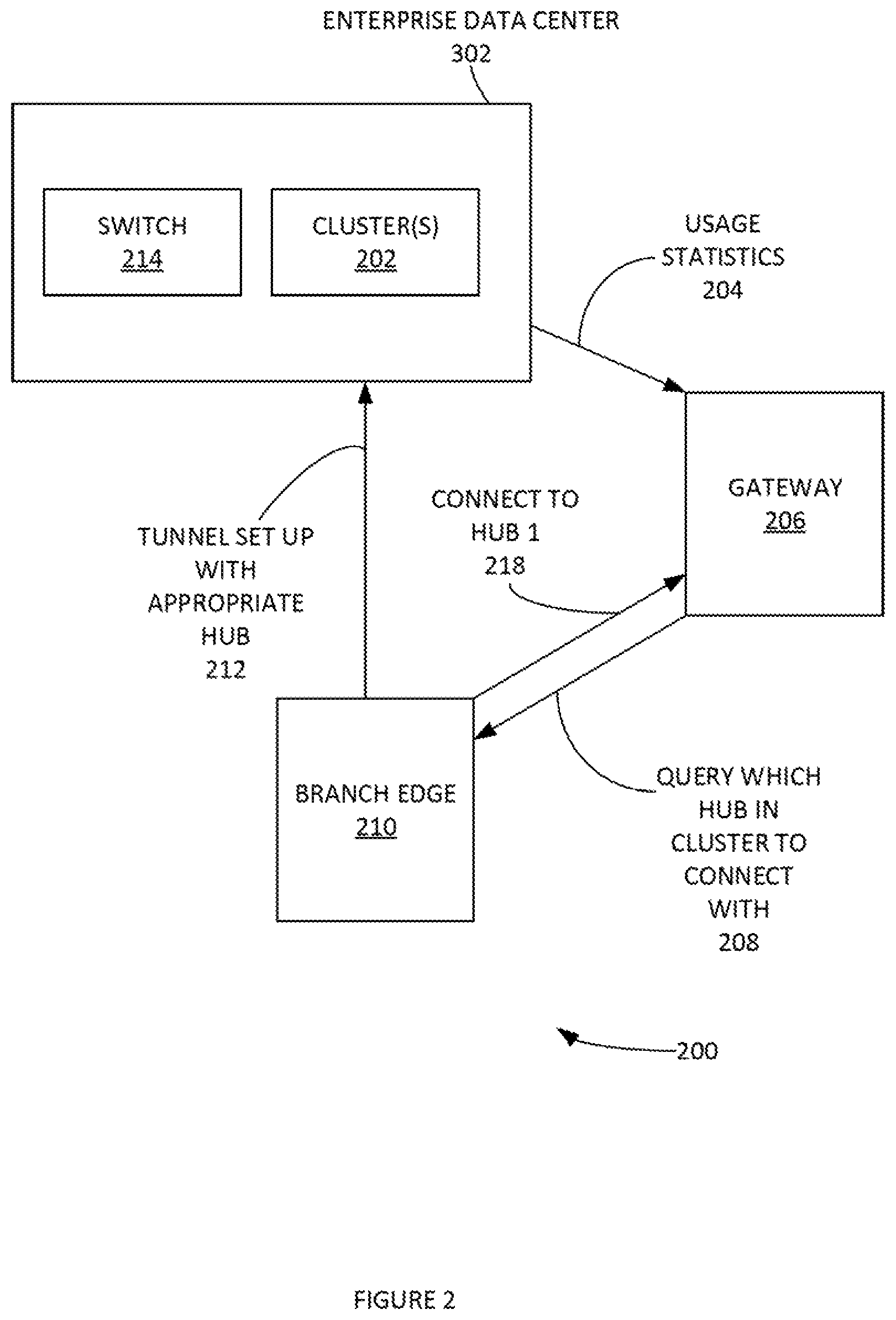
FIGS. 2 and 3 illustrate systems 200 and 300 for implementing process 100, according to some embodiments. Cluster(s) 202 can include various multipath hubs (e.g. Hubs 1-4 502-508 of FIG. 5, etc.). Cluster(s) 202 can communicate various network usage statistics 204 to cluster 206. Cluster(s) 202 can operate in an Enterprise Data Center 302. Branch Edge 210 can communicate a query which hub in cluster to connect with to cluster 206. Cluster 206 can communicate a specific hub identifier to Branch Edge 210 in step 214. Based on this information, branch edge 210 can set up a tunnel with appropriate hub in step 212. Switch 214 can be an L3 switch. Layer 3 switching can be based on (e.g. destination) IP address stored in the header of IP datagram.
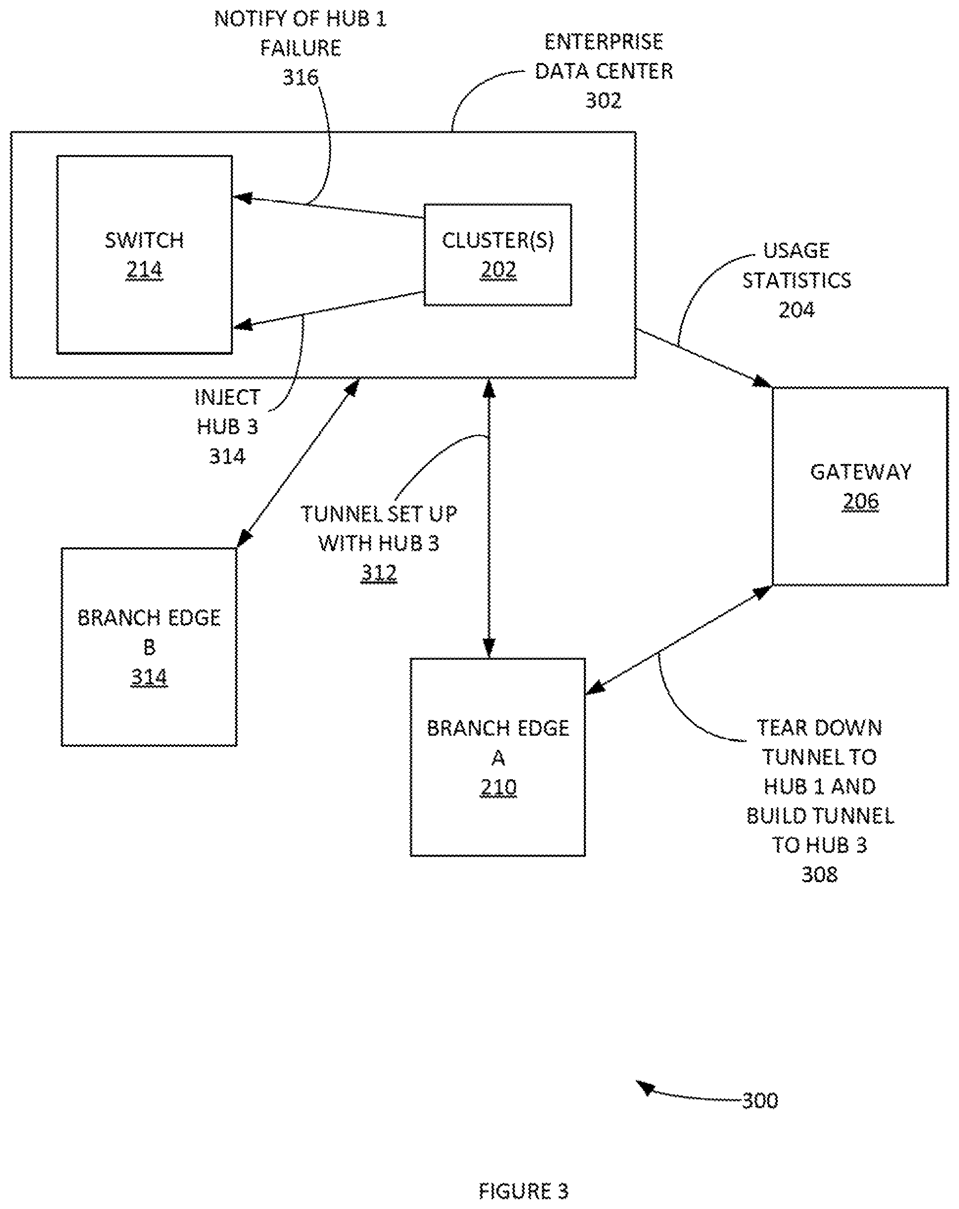
FIG. 3 illustrates an example when a Branch Edge 210 loses connectivity to a multipath Hub of an Enterprise Data Center, according to some embodiments. For example, all tunnels/paths connecting the Edge to the Hub disconnect and the Edge loses all means of connectivity to the Hub. It can again send a connection request to a gateway with the logical ID of Gateway 206, as if it were connecting for the first time. Since the gateway also has a list of connected hubs, if there was truly an outage, it may have also gone dead to the gateway and have been deleted from the list of available Edges that can be assigned from Gateway 206.
Even though in this use case Branch Edge(s) 210 and 314 may be connected to different Hubs in Gateway 206. Gateway 206 can signal the creation of Dynamic Edge-to-Edge tunnels in case both Branch Edge(s) 210 and 314 are not connected to the same Hub in Gateway 206. Gateway 206 can include a controller (not shown) that functions as a control plane piece of the Gateway 206.
FIG. 4 where an Edge A 210 sends traffic from Subnet A 404 to Subnet B 406, according to some embodiments. Edge A 210 can send traffic from Subnet A 404 to Subnet B 406, Hub1 has learned the route for Edge B 314 from the L3 Switch 214 and advertised to Edge A 210 via a routing protocol (e.g. Velocloud.RTM. routing protocol (VCRP), etc.), Edge1 sends the traffic to Hub1. Edge1 can notify the gateway that it has initiated a connection to an IP in B. Traffic for B can be forwarded to the L3 Switch 214. L3 Switch 214 routes traffic to Hub3 as switch 214 has learned that route from Hub3 via a dynamic routing protocol (e.g. OSPF, BGP, etc.). Hub3 sends the traffic to Edge B 314 where it has learned the route for Edge B 314 via a routing protocol. Upon receipt of the message sent in process 100 supra, the gateway determines that Edge A 210 and Edge B 314 can directly connect. The gateway can notify Edge A 210 about connectivity information of Edge B 314. Gateway notifies Edge B 314 about connectivity information of Edge A 210. A dynamic tunnel can be established between Edge A 210 and Edge B 314. Traffic is moved to the direct tunnel and no longer traverses Cluster 206. It is noted that Cluster(s) 202 can operate in an Enterprise Data Center 302 (e.g. Subnet C).
FIG. 5 illustrates an example enterprise data center, according to some embodiments. By way of example, Enterprise data center 202 can include one or more Hubs 1-4 502-508.
FIG. 6 illustrates an example process 600 for connecting when an edge loses connectivity to a hub, according to some embodiments. Process 600 can be implement with system 400 of FIG. 4 and system 500 of FIG. 5. For example, in step 602, Edge A 210 sends traffic from Subnet A 404 to Subnet B 406.
FIG. 7 illustrates an example process 700 of implementing aspects of step 602 or process 600, according to some embodiments. In step 702, Hub 1 502 has learned the route for Edge B 314 from the switch and advertised to Edge A 210 via a routing protocol. In step 704, Edge A 210 sends the traffic to Hub1 502. In step 706, Edge A 210 notifies the gateway that it has initiated a connection to an IP in Subnet B 406.
Returning to process 600, in step 604, traffic for Subnet B 406 is forwarded to the Switch 214. In step 606, the switch routes traffic to Hub 3 506 as the switch has learned that route from Hub 3 506 via a dynamic routing protocol (e.g. OSPF, BGP, etc.). In step 608, Hub 3 506 sends the traffic to Edge B where it has learned the route for B via a routing protocol.
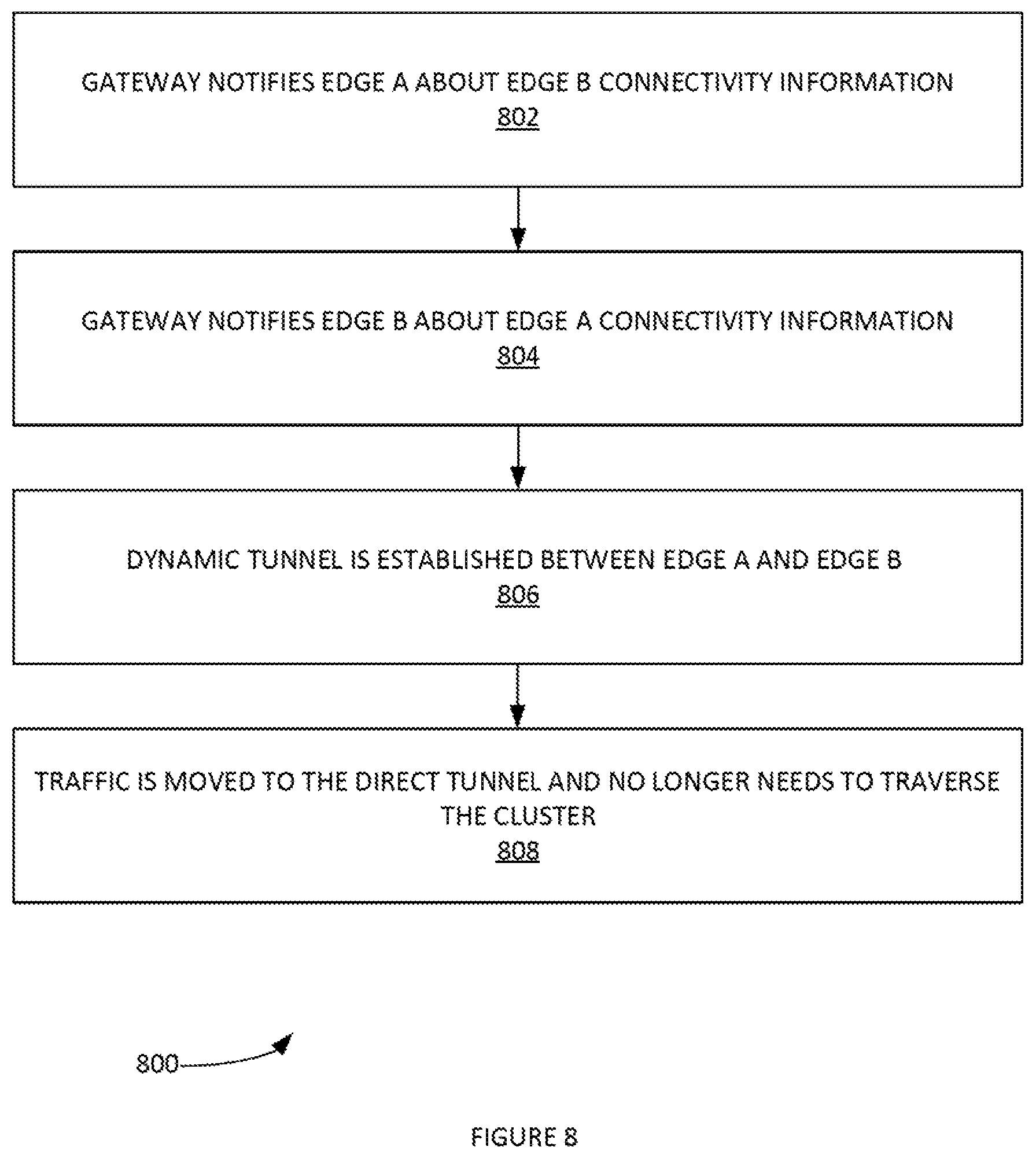
In step 610, upon receipt of the message sent in process 100, the gateway determines that Edge A 210 and Edge B 314 can directly connect. Edge A 210 and Edge B 314 are then connected. FIG. 8 illustrates an example process 800 for implementing aspects of step 610 and/or process 600, according to some embodiments. In step 802, a gateway notifies Edge A 210 about Edge B 314 connectivity information. In step 804, the gateway notifies Edge B 314 about the connectivity information of Edge A 210. In step 806, a dynamic tunnel is established between edge a and Edge B 314. In step 808, traffic is moved to the direct tunnel and no longer needs to traverse cluster 206.
FIG. 9 depicts an exemplary computing system 900 that can be configured to perform any one of the processes provided herein. In this context, computing system 900 may include, for example, a processor, memory, storage, and I/O devices (e.g., monitor, keyboard, disk drive, Internet connection, etc.). However, computing system 900 may include circuitry or other specialized hardware for carrying out some or all aspects of the processes. In some operational settings, computing system 900 may be configured as a system that includes one or more units, each of which is configured to carry out some aspects of the processes either in software, hardware, or some combination thereof.
FIG. 9 depicts computing system 900 with a number of components that may be used to perform any of the processes described herein. The main system 902 includes a motherboard 904 having an I/O section 906, one or more central processing units (CPU) 908, and a memory section 910, which may have a flash memory card 912 related to it. The I/O section 906 can be connected to a display 914, a keyboard and/or other user input (not shown), a disk storage unit 916, and a media drive unit 918. The media drive unit 918 can read/write a computer-readable medium 920, which can contain programs 922 and/or data. Computing system 900 can include a web browser. Moreover, it is noted that computing system 900 can be configured to include additional systems in order to fulfill various functionalities. Computing system 900 can communicate with other computing devices based on various computer communication protocols such a Wi-Fi, Bluetooth.RTM. (and/or other standards for exchanging data over short distances includes those using short-wavelength radio transmissions), USB, Ethernet, cellular, an ultrasonic local area communication protocol, etc.
Conclusion
Although the present embodiments have been described with reference to specific example embodiments, various modifications and changes can be made to these embodiments without departing from the broader spirit and scope of the various embodiments. For example, the various devices, modules, etc. described herein can be enabled and operated using hardware circuitry, firmware, software or any combination of hardware, firmware, and software (e.g., embodied in a machine-readable medium).
In addition, it can be appreciated that the various operations, processes, and methods disclosed herein can be embodied in a machine-readable medium and/or a machine accessible medium compatible with a data processing system (e.g., a computer system), and can be performed in any order (e.g., including using means for achieving the various operations). Accordingly, the specification and drawings are to be regarded in an illustrative rather than a restrictive sense. In some embodiments, the machine-readable medium can be a non-transitory form of machine-readable medium.
* * * * *
D00000
D00001
D00002
D00003
D00004
D00005
D00006
D00007
D00008
D00009
XML
uspto.report is an independent third-party trademark research tool that is not affiliated, endorsed, or sponsored by the United States Patent and Trademark Office (USPTO) or any other governmental organization. The information provided by uspto.report is based on publicly available data at the time of writing and is intended for informational purposes only.
While we strive to provide accurate and up-to-date information, we do not guarantee the accuracy, completeness, reliability, or suitability of the information displayed on this site. The use of this site is at your own risk. Any reliance you place on such information is therefore strictly at your own risk.
All official trademark data, including owner information, should be verified by visiting the official USPTO website at www.uspto.gov. This site is not intended to replace professional legal advice and should not be used as a substitute for consulting with a legal professional who is knowledgeable about trademark law.