Method And System Of A High Availability Enhancements To A Computer Network
MAYYA; AJIT RAMACHANDRA ; et al.
U.S. patent application number 15/838052 was filed with the patent office on 2019-05-09 for method and system of a high availability enhancements to a computer network. The applicant listed for this patent is Nicira, Inc.. Invention is credited to NITIN KUMAR ANANDA, STEPHEN CRAIG CONNORS, AJIT RAMACHANDRA MAYYA, SUNIL MUKUNDAN, PARAG PRITAM THAKORE, STEVEN MICHAEL WOO.
| Application Number | 20190140889 15/838052 |
| Document ID | / |
| Family ID | 66327855 |
| Filed Date | 2019-05-09 |


View All Diagrams
| United States Patent Application | 20190140889 |
| Kind Code | A1 |
| MAYYA; AJIT RAMACHANDRA ; et al. | May 9, 2019 |
METHOD AND SYSTEM OF A HIGH AVAILABILITY ENHANCEMENTS TO A COMPUTER NETWORK
Abstract
In one aspect, a method useful for implementing high availability (HA) enhancements to a computer network, comprising the steps of: providing a first edge device of a local area network (LAN); providing a second edge device of the LAN; providing a gateway system to the LAN from a wide area network; detecting that an HA cable between the first edge device and the second edge device is disconnected; establishing a network connection between the gateway system and the second edge device; with the gateway system: determining that the first edge device is active and passing network traffic, implementing a network tunneling protocol with second edge device.
| Inventors: | MAYYA; AJIT RAMACHANDRA; (Saratoga, CA) ; THAKORE; PARAG PRITAM; (Los gatos, CA) ; CONNORS; STEPHEN CRAIG; (San Jose, CA) ; WOO; STEVEN MICHAEL; (Los Altos, CA) ; MUKUNDAN; SUNIL; (Chennai, IN) ; ANANDA; NITIN KUMAR; (San Jose, CA) | ||||||||||
| Applicant: |
|
||||||||||
|---|---|---|---|---|---|---|---|---|---|---|---|
| Family ID: | 66327855 | ||||||||||
| Appl. No.: | 15/838052 | ||||||||||
| Filed: | December 11, 2017 |
Related U.S. Patent Documents
| Application Number | Filing Date | Patent Number | ||
|---|---|---|---|---|
| 62583733 | Nov 9, 2017 | |||
| Current U.S. Class: | 1/1 |
| Current CPC Class: | H04L 41/12 20130101; H04L 12/4633 20130101; H04L 12/2856 20130101; H04L 12/66 20130101; H04L 41/0654 20130101 |
| International Class: | H04L 12/24 20060101 H04L012/24; H04L 12/66 20060101 H04L012/66 |
Claims
1. A method useful for implementing high availability (HA) enhancements to a computer network, comprising the steps of: providing a first edge device of a local area network (LAN); providing a second edge device of the LAN; providing a gateway system to the LAN from a wide area network; detecting that an HA cable between the first edge device and the second edge device is disconnected; establishing a network connection between the gateway system and the second edge device; with the gateway system: determining that the first edge device is active and passing network traffic, implementing a network tunneling protocol with second edge device, signaling to the second edge device to go into a standby mode, detecting that the first edge device loses connectivity then the gateway, and signaling to the second edge device to take over as the active edge device of the LAN.
Description
CLAIM OF PRIORITY
[0001] This application claims priority to U.S. Provisional Patent Application No. 62/583,733, titled METHOD AND SYSTEM OF A HIGH AVAILABILITY ENHANCEMENTS TO A COMPUTER NETWORK filed on 9 Nov. 2017. This application is hereby incorporated by reference in its entirety.
BACKGROUND
[0002] FIG. 1 (prior art) illustrates an example High Availability (HA) network topology 100, according to some embodiments. There may be two key deficiencies in HA network topology 100 which are addressed by the enhancements in FIGS. 2-10. A first deficiency can include the requirement of a switch on the WAN side of the HA pair (e.g. first edge device 112 and second edge device 114). The WAN can include MPLS 102 and Internet 108. A single switch may introduce a single point of failure in actuality two WAN-side switches are required for full redundancy. The addition of two switches (e.g. switches 116 and 120) may increases the complexity of the insertion without providing any real benefit. After the installation of an Edge Router, a customer may be responsible for the switch.
[0003] Additionally, unpredictable behavior in split brain scenarios may arise Typically the switches may run a Spanning Tree Protocol to prevent loops in the network. If both devices go active (e.g. HA cable 118 is disconnected), then each switch may block a different device, causing a total loss of traffic through the pair.
BRIEF SUMMARY OF THE INVENTION
[0004] In one aspect, a method useful for implementing high availability (HA) enhancements to a computer network, comprising the steps of: providing a first edge device of a local area network (LAN); providing a second edge device of the LAN; providing a gateway system to the LAN from a wide area network; detecting that an HA cable between the first edge device and the second edge device is disconnected; establishing a network connection between the gateway system and the second edge device; with the gateway system: determining that the first edge device is active and passing network traffic, implementing a network tunneling protocol with second edge device, signaling to the second edge device to go into a standby mode, detecting that the first edge device loses connectivity then the gateway, and signaling to the second edge device to take over as the active edge device of the LAN.
BRIEF DESCRIPTION OF THE DRAWINGS
[0005] FIG. 1 (prior art) illustrates an example High Availability (HA) network topology, according to some embodiments.
[0006] FIG. 2 illustrates an example network topology with a switch on a WAN side of a HA pair, according to some embodiments.
[0007] FIG. 3 illustrates an example network topology, according to some embodiments.
[0008] FIGS. 4 A-B illustrates a network topology illustrating a first use case that covers edge device with shared links, according to some embodiments.
[0009] FIGS. 5 A-B illustrate network topology illustrating a second use case that includes a scenario where there is only one link connected to each edge device (e.g. edge devices with unique links), according to some embodiments.
[0010] FIG. 6 illustrates another example network topology, according to some embodiments.
[0011] FIG. 7 illustrates another example network topology 700 with an active LAN, according to some embodiments.
[0012] FIG. 8 illustrates yet another example network topology, according to some embodiments.
[0013] FIG. 9 illustrates an ample communication exchange process, according to some embodiments.
[0014] FIG. 10 illustrates an example process for implementing dynamic HA mode based process 1000 on current WAN connectivity, according to some embodiments.
[0015] FIG. 11 depicts an exemplary computing system that can be configured to perform any one of the processes provided herein.
[0016] FIG. 12 illustrates an example process for providing dynamic HA mode based on current WAN connectivity, according to some embodiments.
[0017] The Figures described above are a representative set, and are not exhaustive with respect to embodying the invention.
DESCRIPTION
[0018] Disclosed are a system, method, and article of manufacture for method and system of a high availability enhancements to a computer network. The following description is presented to enable a person of ordinary skill in the art to make and use the various embodiments. Descriptions of specific devices, techniques, and applications are provided only as examples. Various modifications to the examples described herein can be readily apparent to those of ordinary skill in the art, and the general principles defined herein may be applied to other examples and applications without departing from the spirit and scope of the various embodiments.
[0019] Reference throughout this specification to "one embodiment," "an embodiment," `one example,` or similar language means that a particular feature, structure, or characteristic described in connection with the embodiment is included in at least one embodiment of the present invention. Thus, appearances of the phrases "in one embodiment," "in an embodiment," and similar language throughout this specification may, but do not necessarily, all refer to the same embodiment.
[0020] Furthermore, the described features, structures, or characteristics of the invention may be combined in any suitable manner in one or more embodiments. In the following description, numerous specific details are provided, such as examples of programming, software modules, user selections, network transactions, database queries, database structures, hardware modules, hardware circuits, hardware chips, etc., to provide a thorough understanding of embodiments of the invention. One skilled in the relevant art can recognize, however, that the invention may be practiced without one or more of the specific details, or with other methods, components, materials, and so forth. In other instances, well-known structures, materials, or operations are not shown or described in detail to avoid obscuring aspects of the invention.
[0021] The schematic flow chart diagrams included herein are generally set forth as logical flow chart diagrams. As such, the depicted order and labeled steps are indicative of one embodiment of the presented method. Other steps and methods may be conceived that are equivalent in function, logic, or effect to one or more steps, or portions thereof, of the illustrated method. Additionally, the format and symbols employed are provided to explain the logical steps of the method and are understood not to limit the scope of the method. Although various arrow types and line types may be employed in the flow chart diagrams, and they are understood not to limit the scope of the corresponding method. Indeed some, arrows or other connectors may be used to indicate only the logical flow of the method. For instance, an arrow may indicate a waiting or monitoring period of unspecified duration between enumerated steps of the depicted method. Additionally, the order in which a particular method occurs may or may not strictly adhere to the order of the corresponding steps shown.
DEFINITIONS
[0022] Example definitions for some embodiments are now provided.
[0023] Address Resolution Protocol (ARP) is a communications protocol used for discovering the link layer address associated with a given Internet layer address, a critical function in the Internet protocol suite.
[0024] CE router (customer edge router) can be a router located on the customer premises that provides an Ethernet interface between the customer's LAN and the provider's core network. CE routers can be a component in an MPLS architecture.
[0025] Dynamic tunneling can refer to Multi Path tunnels (i.e. paths) that are established on-demand between two endpoints when there is VPN traffic to be sent between two Edges, and torn down after VPN traffic is completed.
[0026] Edge device can be a device that provides an entry point into enterprise or service provider core networks. An edge device can be software running in a virtual machine (VM) located in a branch office and/or customer premises.
[0027] Gateway can be a node (e.g. a router) on a computer network that serves as an access point to another network.
[0028] LAN is a local area network, a computer network covering a small local area.
[0029] Multiprotocol Label Switching (MPLS) is a type of data-carrying technique for high-performance telecommunications networks. MPLS directs data from one network node to the next based on short path labels rather than long network addresses, avoiding complex lookups in a routing table. The labels identify virtual links (paths) between distant nodes rather than endpoints. MPLS can encapsulate packets of various network protocols.
[0030] Orchestrator can include a software component that provides multi-tenant and role based centralized configuration management and visibility.
[0031] Split brain can refer to data or availability inconsistencies originating from the maintenance of two separate data sets with overlap in scope, either because of servers in a network design, or a failure condition based on servers not communicating and synchronizing their data to each other.
[0032] Tunneling protocol can allow a network user to access or provide a network service that the underlying network does not support or provide directly.
[0033] Wide area network (WAN) is a telecommunications network or computer network that extends over a large geographical distance.
[0034] Virtual private network (VPN) can extend a private network across a public network, such as the Internet. It can enable users to send and receive data across shared or public networks as if their computing devices were directly connected to the private network, and thus benefit from the functionality, security and management policies of the private network.
[0035] Additional example definitions are provided herein.
Examples Systems and Processes
[0036] It is noted that the following systems and methods are backwards compatible with existing HA deployments, thus requiring no changes to existing user interfaces.
[0037] FIG. 2 illustrates an example network topology 200 with a switch on a WAN side of a HA pair, according to some embodiments. It noted that an HA switch may no longer be required on the WAN side of the HA pair. Instead, a customer can connect one or more WAN links to each of the edge devices 212, 214 in the pair (e.g. via customer router 206 and/or modem 210). The devices can then synchronize their connected interface status. If the active edge device 212 or both edge devices 212, 214 have the same interface connected, then this can be initiated directly. If only a standby edge 214 has an interface connected, then connectivity can be enabled through the standby edge 214 by bridging the tunnels (e.g. tunnel B 222 to tunnel A 220) across the HA cable 218 and out the peer WAN link.
[0038] Now that each of the edge devices 212, 214 has its own individual set of WAN connections, a split-brain scenario can be easily determined by a gateway which has a full view of what is happening from the perspective of both edge devices 212, 214.
[0039] It is noted that each of the edge devices 212, 214 has its own individual set of WAN connections, a split-brain scenario can be determined by the Gateway. The Gateway can have a full view of the state of each of the edge devices 212, 214 from the perspective of both edge devices 212, 214.
[0040] FIG. 3 illustrates an example network topology 300, according to some embodiments. As shown, a high availability (HA) cable 318 can be disconnected. Each of the edge devices 312, 314 can establish a tunnel (e.g. tunnels A and B 320, 322) directly with a gateway system. The gateway system can determine that an edge is connected, active and passing traffic. The gateway system can open a tunnel to the second edge. The gateway system can signal to the edge to go to standby on the local LAN 318. If it is detected that the edge loses connectivity, then the gate system can signal to the other edge to become the active edge. Network topology 300 can be used to implement process 1000 provided below.
[0041] A dynamic HA mode based on current WAN connectivity can be implemented. It is noted that a WAN switch is no longer required for HA deployments as links may be connected to individual edge devices. This can be accomplished by leveraging the link state which is already synchronized between the edge devices and, using a standby edge as a virtual switch to reach links attached to the standby edge only.
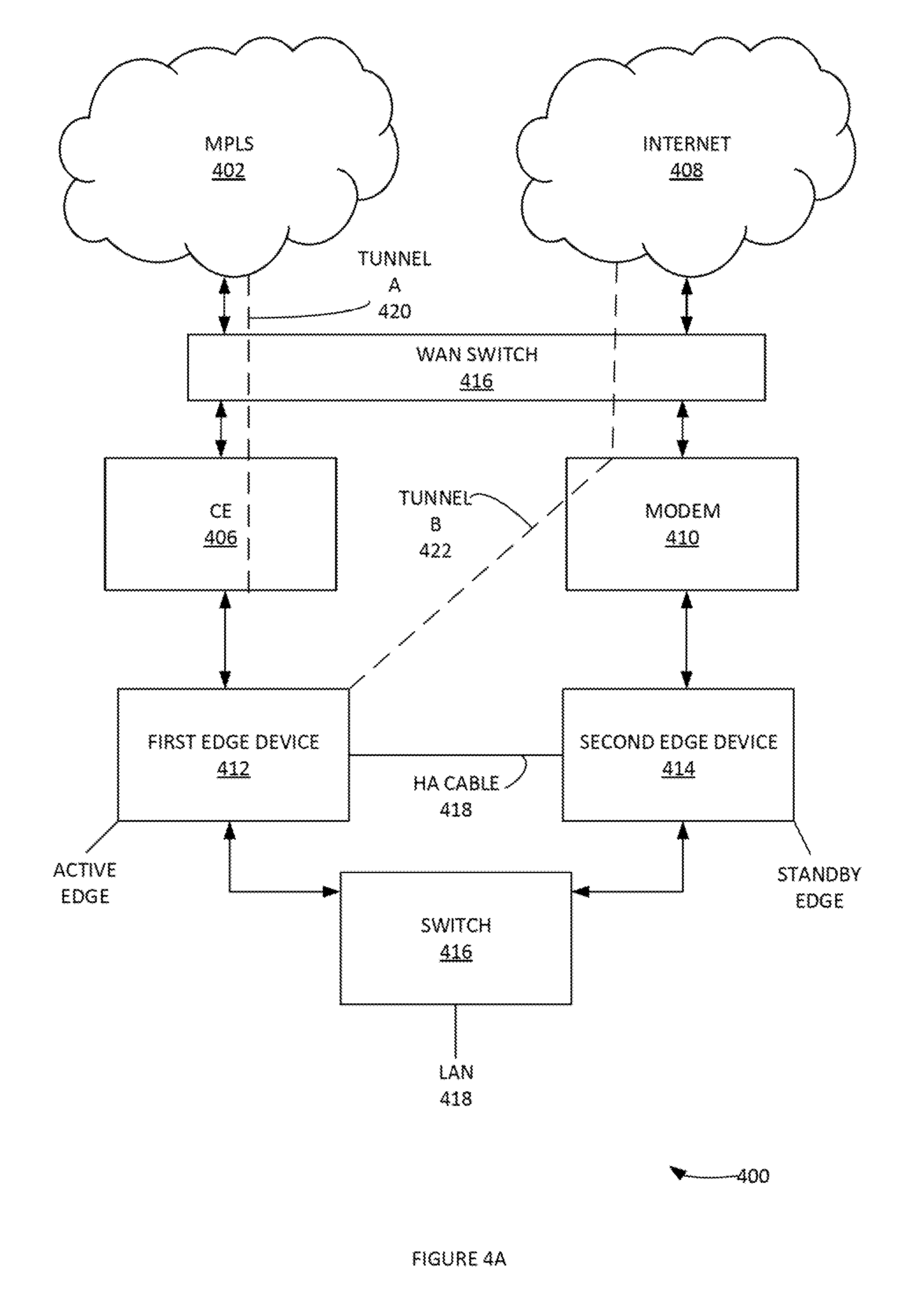
[0042] FIGS. 4 A-B illustrates a network topology 400 illustrating a first use case that covers edge device with shared links (e.g. backwards compatibility), according to some embodiments. More specifically, FIG. 4A illustrates an initial state and FIG. 4B illustrates an HA failover state. The first edge device 412 can have two links connected while the second edged device 414 only has one link connected. Accordingly, the first edge device 412 can be the preferred edge and by default the active edge. As the first edge device 412 has local connectivity to both links, both tunnels (e.g. tunnels A and B 420 422) can be initiated directly from the first edge device 412. If there is an HA failover, the second edge device 414 can only have access to the link that is directly connected to it.
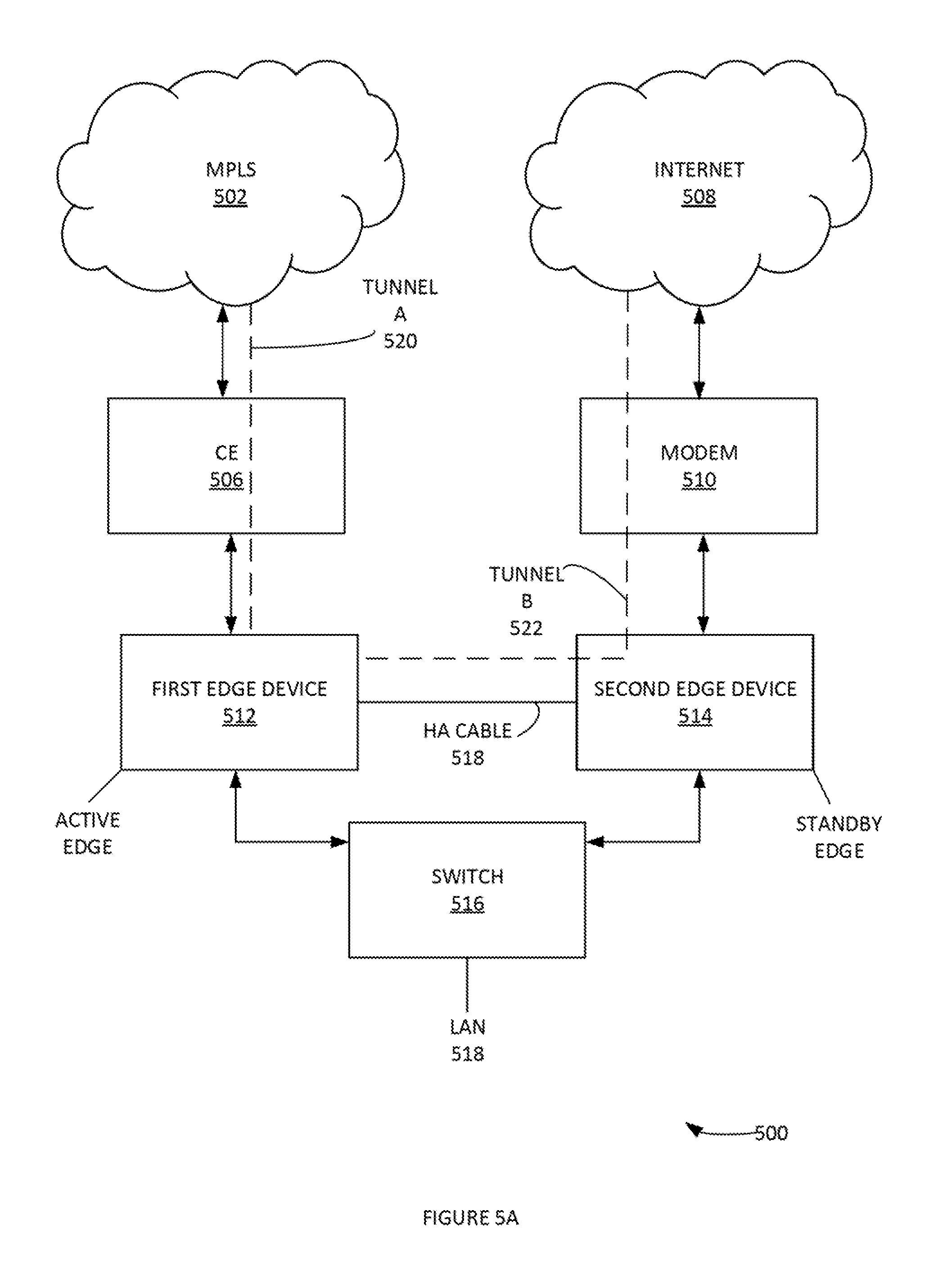
[0043] FIGS. 5 A-B illustrate network topology 500 illustrating a second use case that includes a scenario where there is only one link connected to each edge device (e.g. edge devices with unique links), according to some embodiments. More specifically, FIG. 5A illustrates an initial state and FIG. 5B illustrates an HA failover state. The first edge device 512 can have MPLS 502 connected and the second edge device 514 has the public internet 508 connected. Accordingly, the first edge device 512 the preferred edge and by default the active edge. As the first edge device 512 does not have local connectivity to the Internet link, that tunnel (e.g. tunnel B 522) can be initiated by proxying through the second edge device 514. If there is an HA failover, the second edge device 514 can only have access to a link with which it is directly connected.
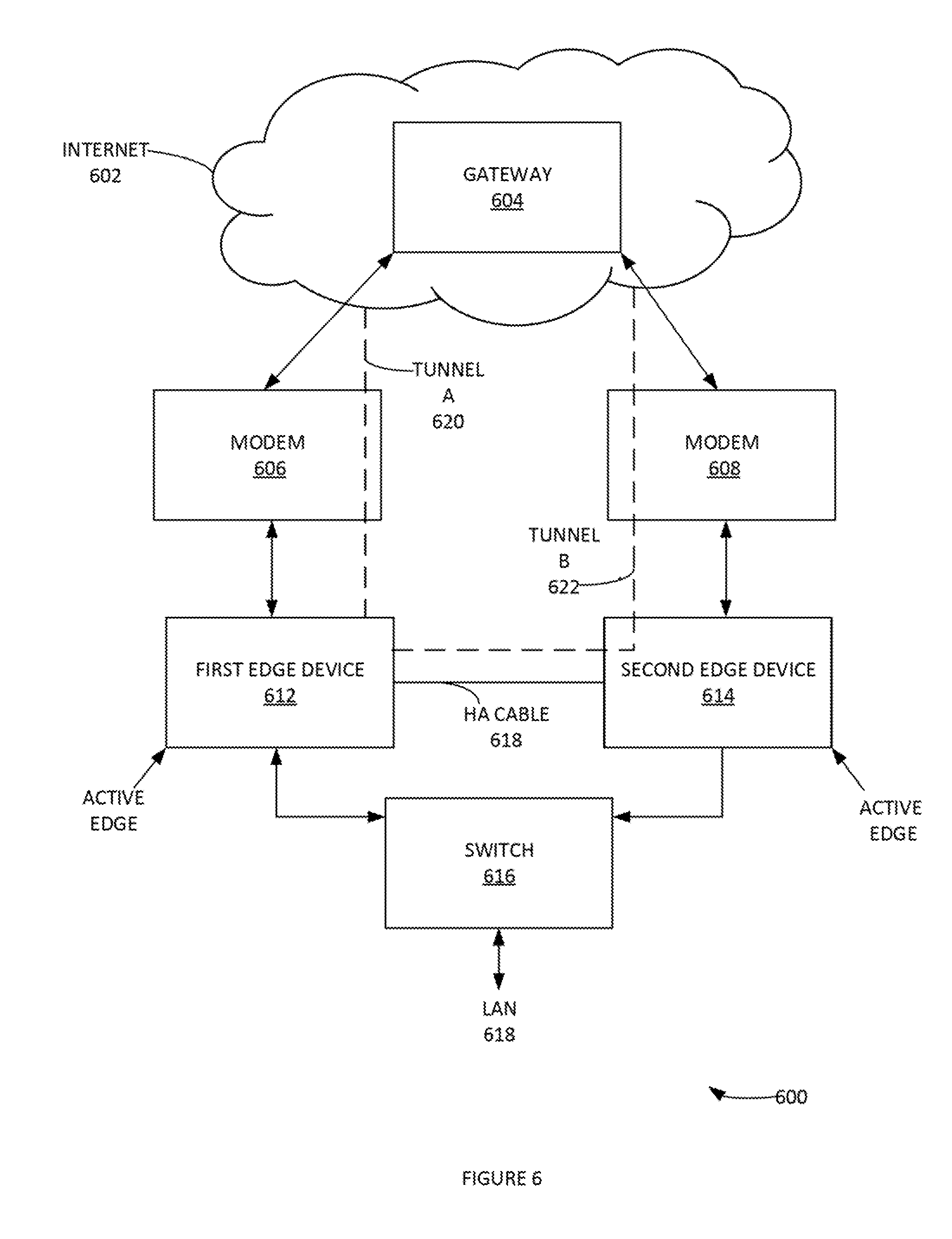
[0044] FIG. 6 illustrates another example network topology 600, according to some embodiments. As noted in FIGS. 5 A-B, an edge device can be connected to two WAN links. A first WAN link can be connected locally, and a second WAN link can be proxied via the second edge device 614. For simplicity this can be presented as two public Internet links, however it could also be accomplished with hybrid links, as long as, a private WAN link can reach a gateway (e.g. partner gateway deployment, SD-WAN service reachable enabled, etc.).
[0045] FIG. 7 illustrates another example network topology 700 with an active LAN, according to some embodiments. Gateway 704 can have a pre-existing connection to a first edge device 712. Edge device 712 can be the preferred active edge. Second edge device 714 (e.g. with the same logical ID) can be connected on a different WAN link. Gateway 704 can maintain tunnel B 722 as an active tunnel for future use. Gateway 704 can signal the second edge device 714 to go into standby mode on the LAN. This process can be used to logically prevent the split-brain scenario from occurring. LAN can connect with edge devices 712, 714 via active LAN that responds to ARP 722. FIG. 8 illustrates yet another example network topology, according to some embodiments.
[0046] FIG. 9 illustrates an example communication exchange process 900, according to some embodiments. In step 902, gateway receives MP_INIT, but sees a first edge device is active and sets GO_STANDBY flag in MP_INIT_ACK. In step 904, edge receives GO_STANDBY flag in MP_INIT_ACK, goes back into standby mode on the LAN, but keeps the tunnel established by gateway. In step 906, the gateway receives confirmation that a second edge device is in standby mode. If first edge device tunnel(s) become unavailable, then the second edge device can be signaled to become active. Following the exchange, the split-brain scenario can have been cleared. For example, Gateway receives tunnel initiation request from 714 but sees that 712 is already active. The Gateway responds to the tunnel initiation request but sets a flag in the response indicating that the 714 device can go into a standby mode on the LAN.
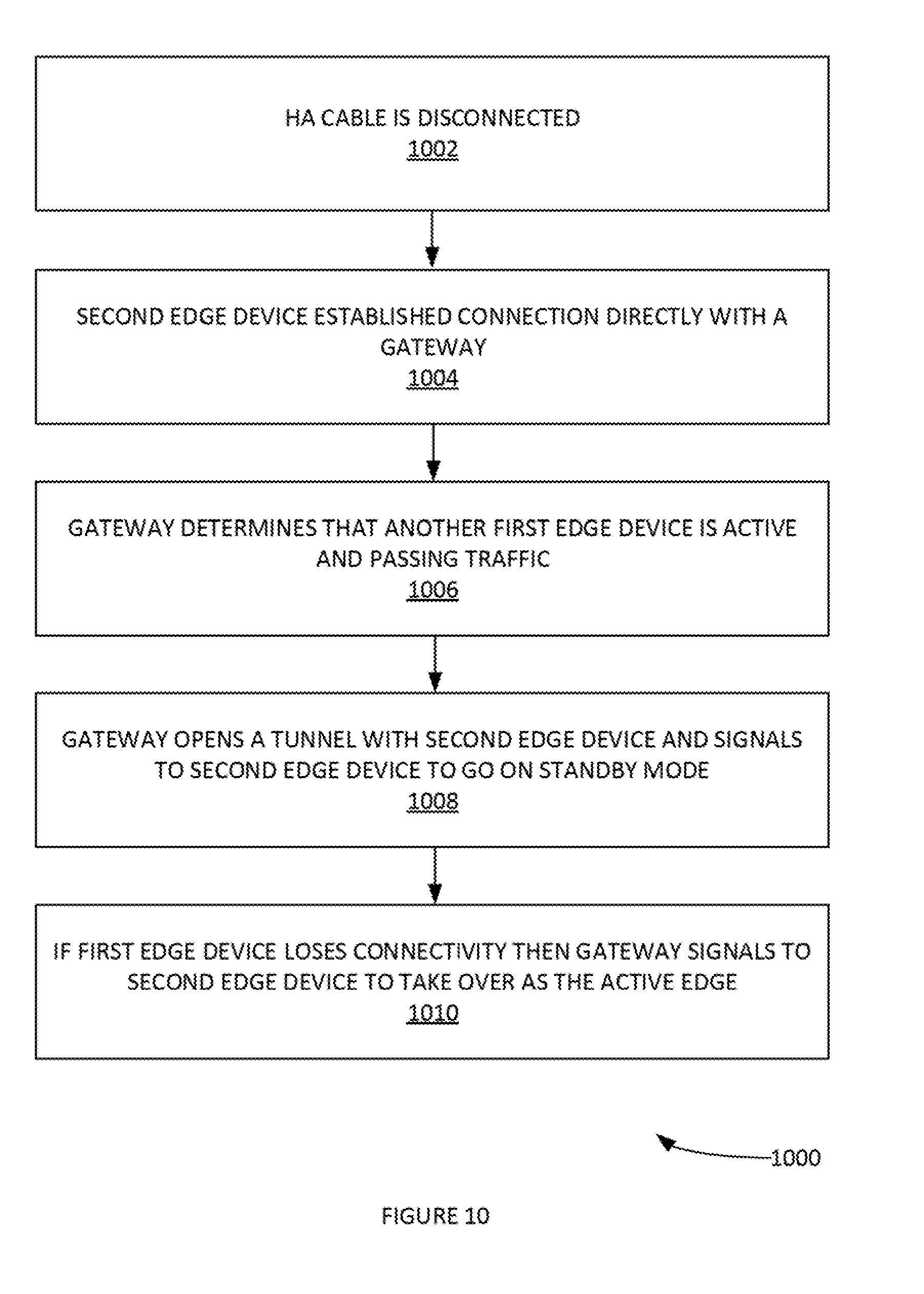
[0047] FIG. 10 illustrates an example process for implementing dynamic HA mode based process 1000 on current WAN connectivity, according to some embodiments. In step 1002, the HA cable can be disconnected. In step 1004, the second edge device established a communicative network connection directly with a gateway system. In step 1006, the gateway determines that another first edge, device is active and passing network traffic to a LAN. In step 1008, the gateway opens a tunnel with second edge device and signals to second edge device to go on standby mode. In step 1010, if the first edge device loses connectivity then gateway signals to second edge device to take over as the active edge.
[0048] FIG. 11 depicts an exemplary computing system 1100 that can be configured to perform any one of the processes provided herein. In this context, computing system 1100 may include, for example a processor, memory, storage, and I/O devices (e.g., monitor, keyboard, disk drive, Internet connection, etc.). However, computing system 1100 may include circuitry or other specialized hardware for carrying out some or all aspects of the processes. In some operational settings, computing system 1100 may be configured as a system that includes one or more units, each of which is configured to carry out some aspects of the processes either in software, hardware, or some combination thereof.
[0049] FIG. 11 depicts computing system 1100 with a number of components that may be used to perform any of the processes described herein. The main system 1102 includes a motherboard 1104 having an I/O section 1106, one or e central processing units (CPU) 1108, and a memory section 1110, which may have a flash memory card 1112 related to it. The I/O section 1106 can be connected to a display 1114, a keyboard and/or other user input (not shown), a disk storage unit 1116, and a media drive unit 1118. The media drive unit 1118 can read/write a computer-readable medium 1120, which can contain programs 1122 and/or data. Computing system 1100 can include a web browser. Moreover, it is noted that computing system 1100 can be configured to include additional systems in order to fulfill various functionalities. Computing system 1100 can communicate with other computing devices based on various computer communication protocols such a Wi-Fi Bluetooth.RTM. (and/or other standards for exchanging data over short distances includes those using short-wavelength radio transmissions), USB, Ethernet, cellular, an ultrasonic local area communication protocol, etc.
[0050] FIG. 12 illustrates an example process 1200 for providing dynamic HA mode based on current WAN connectivity, according to some embodiments. In step 1202, process 1200 can synchronize the state of links that are connected to each individual edge. In step 1204, if the link is connected to first edge, device only (and/or both edges in some example embodiments), then process 1200 can initiate tunnels locally. In step 1206, if a link is connected to second edge device and not first, then process 1200 can initiate tunnels via a proxy over HA cable. Dynamic HA Mode election can be used to determine whether there is a WAN Switch providing connectivity to the same link via both edge devices or separate links connected to independent edge devices, and then automatically initiating tunnels locally or via proxy based on auto-detecting this.
CONCLUSION
[0051] Although the present embodiments have been described with reference to specific example embodiments, various modifications and changes can be made to these embodiments without departing from the broader spirit and scope of the various embodiments. For example, the various devices, modules, etc. described herein can be enabled and operated using hardware circuitry, firmware, software or any combination of hardware, firmware, and software (e.g., embodied in a machine-readable medium).
[0052] In addition, it can be appreciated that the various operations, processes, and methods disclosed herein can be embodied in a machine-readable medium and/or a machine accessible medium compatible with a data processing system (e.g., a computer system), and can be performed in any order (e.g., including using means for achieving the various operations). Accordingly, the specification and drawings are to be regarded in an illustrative rather than a restrictive sense. In some embodiments, the machine-readable medium can be a non-transitory form of machine-readable medium.
* * * * *
D00000
D00001
D00002
D00003
D00004
D00005
D00006
D00007
D00008
D00009
D00010
D00011
D00012
D00013

D00014

XML
uspto.report is an independent third-party trademark research tool that is not affiliated, endorsed, or sponsored by the United States Patent and Trademark Office (USPTO) or any other governmental organization. The information provided by uspto.report is based on publicly available data at the time of writing and is intended for informational purposes only.
While we strive to provide accurate and up-to-date information, we do not guarantee the accuracy, completeness, reliability, or suitability of the information displayed on this site. The use of this site is at your own risk. Any reliance you place on such information is therefore strictly at your own risk.
All official trademark data, including owner information, should be verified by visiting the official USPTO website at www.uspto.gov. This site is not intended to replace professional legal advice and should not be used as a substitute for consulting with a legal professional who is knowledgeable about trademark law.