Stapler with auto-matic lockout mechanism
Murugesan Sept
U.S. patent number 10,772,627 [Application Number 15/535,072] was granted by the patent office on 2020-09-15 for stapler with auto-matic lockout mechanism. This patent grant is currently assigned to Covidien LP. The grantee listed for this patent is Covidien LP. Invention is credited to Ganesan Murugesan.


| United States Patent | 10,772,627 |
| Murugesan | September 15, 2020 |
Stapler with auto-matic lockout mechanism
Abstract
A surgical stapling device (10) is provided that includes a handle assembly (12), a movable trigger (26) and an elongated body portion (14). A staple containing shell assembly (22) is mounted on a distal end of the elongated body portion (14) and an anvil assembly (20) is movably mounted relative to the staple containing shell assembly (22). An auto-lock safety mechanism (40) is provided to prevent secondary actuation of the surgical stapling device after initial actuation. The auto-lock safety mechanism (40) includes a primary lock or slider assembly (42) for blocking movement of the trigger (26) and a secondary lock or stopper (44) for blocking movement of the slider assembly (42) prior to approximation of the anvil assembly (20) relative to the staple containing shell assembly (22). A slider (70) is urged to a locked or blocking position by a biasing member (72).
| Inventors: | Murugesan; Ganesan (Minhang District, CN) | ||||||||||
|---|---|---|---|---|---|---|---|---|---|---|---|
| Applicant: |
|
||||||||||
| Assignee: | Covidien LP (Mansfield,
MA) |
||||||||||
| Family ID: | 1000005052226 | ||||||||||
| Appl. No.: | 15/535,072 | ||||||||||
| Filed: | December 11, 2014 | ||||||||||
| PCT Filed: | December 11, 2014 | ||||||||||
| PCT No.: | PCT/CN2014/093575 | ||||||||||
| 371(c)(1),(2),(4) Date: | June 12, 2017 | ||||||||||
| PCT Pub. No.: | WO2016/090600 | ||||||||||
| PCT Pub. Date: | June 16, 2016 |
Prior Publication Data
| Document Identifier | Publication Date | |
|---|---|---|
| US 20170348002 A1 | Dec 7, 2017 | |
| Current U.S. Class: | 1/1 |
| Current CPC Class: | A61B 17/1155 (20130101); A61B 17/07207 (20130101); A61B 2017/00367 (20130101); A61B 2090/0814 (20160201); A61B 2017/07278 (20130101); A61B 2017/07257 (20130101) |
| Current International Class: | A61B 17/00 (20060101); A61B 17/072 (20060101); A61B 17/115 (20060101); A61B 90/00 (20160101) |
| Field of Search: | ;606/143 |
References Cited [Referenced By]
U.S. Patent Documents
| 3193165 | July 1965 | Akhalaya et al. |
| 3388847 | June 1968 | Kasulin et al. |
| 3552626 | January 1971 | Astafiev et al. |
| 3638652 | February 1972 | Kelley |
| 3771526 | November 1973 | Rudie |
| 4198982 | April 1980 | Fortner et al. |
| 4207898 | June 1980 | Becht |
| 4289133 | September 1981 | Rothfuss |
| 4304236 | December 1981 | Conta et al. |
| 4319576 | March 1982 | Rothfuss |
| 4350160 | September 1982 | Kolesov et al. |
| 4351466 | September 1982 | Noiles |
| 4379457 | April 1983 | Gravener et al. |
| 4473077 | September 1984 | Noiles et al. |
| 4476863 | October 1984 | Kanshin et al. |
| 4485817 | December 1984 | Swiggett |
| 4488523 | December 1984 | Shichman |
| 4505272 | March 1985 | Utyamyshev et al. |
| 4505414 | March 1985 | Filipi |
| 4520817 | June 1985 | Green |
| 4550870 | November 1985 | Krumme et al. |
| 4573468 | March 1986 | Conta et al. |
| 4576167 | March 1986 | Noiles |
| 4592354 | June 1986 | Rothfuss |
| 4603693 | August 1986 | Conta et al. |
| 4606343 | August 1986 | Conta et al. |
| 4632290 | December 1986 | Green et al. |
| 4646745 | March 1987 | Noiles |
| 4665917 | May 1987 | Clanton et al. |
| 4667378 | May 1987 | Sturm |
| 4667673 | May 1987 | Li |
| 4671445 | June 1987 | Barker et al. |
| 4700703 | October 1987 | Resnick et al. |
| 4703887 | November 1987 | Clanton et al. |
| 4708141 | November 1987 | Inoue et al. |
| 4717063 | January 1988 | Ebihara |
| 4752024 | June 1988 | Green et al. |
| 4754909 | July 1988 | Barker et al. |
| 4776506 | October 1988 | Green |
| 4817847 | April 1989 | Redtenbacher et al. |
| 4873977 | October 1989 | Avant et al. |
| 4893662 | January 1990 | Gervasi |
| 4903697 | February 1990 | Resnick et al. |
| 4907591 | March 1990 | Vasconcellos et al. |
| 4917114 | April 1990 | Green et al. |
| 4957499 | September 1990 | Lipatov et al. |
| 4962877 | October 1990 | Hervas |
| 5005749 | April 1991 | Aranyi |
| 5042707 | August 1991 | Taheri |
| 5047039 | September 1991 | Avant et al. |
| 5104025 | April 1992 | Main et al. |
| 5119983 | June 1992 | Green et al. |
| 5122156 | June 1992 | Granger et al. |
| 5139513 | August 1992 | Segato |
| 5158222 | October 1992 | Green et al. |
| 5188638 | February 1993 | Tzakis |
| 5193731 | March 1993 | Aranyi |
| 5197648 | March 1993 | Gingold |
| 5197649 | March 1993 | Bessler et al. |
| 5205459 | April 1993 | Brinkerhoff et al. |
| 5221036 | June 1993 | Takase |
| 5222963 | June 1993 | Brinkerhoff et al. |
| 5253793 | October 1993 | Green et al. |
| 5261920 | November 1993 | Main et al. |
| 5271543 | December 1993 | Grant et al. |
| 5271544 | December 1993 | Fox et al. |
| 5275322 | January 1994 | Brinkerhoff et al. |
| 5282810 | February 1994 | Allen et al. |
| 5285944 | February 1994 | Green et al. |
| 5285945 | February 1994 | Brinkerhoff et al. |
| 5292053 | March 1994 | Bilotti et al. |
| 5309927 | May 1994 | Welch |
| 5312024 | May 1994 | Grant et al. |
| 5314435 | May 1994 | Green et al. |
| 5314436 | May 1994 | Wilk |
| 5330486 | July 1994 | Wilk |
| 5333773 | August 1994 | Main et al. |
| 5344059 | September 1994 | Green et al. |
| 5346115 | September 1994 | Perouse et al. |
| 5348259 | September 1994 | Blanco et al. |
| 5350104 | September 1994 | Main et al. |
| 5355897 | October 1994 | Pietrafitta et al. |
| 5360154 | November 1994 | Green |
| 5368215 | November 1994 | Green et al. |
| 5392979 | February 1995 | Green et al. |
| 5395030 | March 1995 | Kuramoto et al. |
| 5403333 | April 1995 | Kaster et al. |
| 5404870 | April 1995 | Brinkerhoff et al. |
| 5411508 | May 1995 | Bessler et al. |
| 5425738 | June 1995 | Gustafson et al. |
| 5433721 | July 1995 | Hooven et al. |
| 5437684 | August 1995 | Calabrese et al. |
| 5439156 | August 1995 | Grant et al. |
| 5443198 | August 1995 | Viola et al. |
| 5447513 | September 1995 | Davison |
| 5447514 | September 1995 | Gerry et al. |
| 5454825 | October 1995 | Van Leeuwen et al. |
| 5464415 | November 1995 | Chen |
| 5470006 | November 1995 | Rodak |
| 5474223 | December 1995 | Viola et al. |
| 5497934 | March 1996 | Brady et al. |
| 5503635 | April 1996 | Sauer et al. |
| 5522534 | June 1996 | Viola et al. |
| 5533661 | July 1996 | Main et al. |
| 5588579 | December 1996 | Schnut et al. |
| 5609285 | March 1997 | Grant et al. |
| 5626591 | May 1997 | Kockerling et al. |
| 5632433 | May 1997 | Grant et al. |
| 5639008 | June 1997 | Gallagher et al. |
| 5641111 | June 1997 | Ahrens et al. |
| 5658300 | August 1997 | Bito et al. |
| 5669918 | September 1997 | Balazs et al. |
| 5685474 | November 1997 | Seeber |
| 5709335 | January 1998 | Heck |
| 5715987 | February 1998 | Kelley et al. |
| 5718360 | February 1998 | Green et al. |
| 5720755 | February 1998 | Dakov |
| 5732872 | March 1998 | Bolduc et al. |
| 5749896 | May 1998 | Cook |
| 5758814 | June 1998 | Gallagher et al. |
| 5799857 | September 1998 | Robertson et al. |
| 5814055 | September 1998 | Knodel et al. |
| 5833698 | November 1998 | Hinchliffe et al. |
| 5836503 | November 1998 | Ehrenfels et al. |
| 5839639 | November 1998 | Sauer et al. |
| 5855312 | January 1999 | Toledano |
| 5860581 | January 1999 | Robertson et al. |
| 5868760 | February 1999 | McGuckin, Jr. |
| 5881943 | March 1999 | Heck et al. |
| 5915616 | June 1999 | Viola et al. |
| 5947363 | September 1999 | Bolduc et al. |
| 5951576 | September 1999 | Wakabayashi |
| 5957363 | September 1999 | Heck |
| 5993468 | November 1999 | Rygaard |
| 6024748 | February 2000 | Manzo et al. |
| 6050472 | April 2000 | Shibata |
| 6053390 | April 2000 | Green et al. |
| 6068636 | May 2000 | Chen |
| 6083241 | July 2000 | Longo et al. |
| 6102271 | August 2000 | Longo et al. |
| 6117148 | September 2000 | Ravo et al. |
| 6119913 | September 2000 | Adams et al. |
| 6126058 | October 2000 | Adams et al. |
| 6142933 | November 2000 | Longo et al. |
| 6149667 | November 2000 | Hovland et al. |
| 6176413 | January 2001 | Heck et al. |
| 6179195 | January 2001 | Adams et al. |
| 6193129 | February 2001 | Bittner et al. |
| 6203553 | March 2001 | Robertson et al. |
| 6209773 | April 2001 | Bolduc et al. |
| 6241140 | June 2001 | Adams et al. |
| 6253984 | July 2001 | Heck et al. |
| 6258107 | July 2001 | Balazs et al. |
| 6261302 | July 2001 | Voegele |
| 6264086 | July 2001 | McGuckin, Jr. |
| 6269997 | August 2001 | Balazs et al. |
| 6273897 | August 2001 | Dalessandro et al. |
| 6279809 | August 2001 | Nicolo |
| 6302311 | October 2001 | Adams et al. |
| 6338737 | January 2002 | Toledano |
| 6343731 | February 2002 | Adams et al. |
| 6387105 | May 2002 | Gifford, III et al. |
| 6398795 | June 2002 | McAlister et al. |
| 6402008 | June 2002 | Lucas |
| 6439446 | August 2002 | Perry et al. |
| 6443973 | September 2002 | Whitman |
| 6450390 | September 2002 | Heck et al. |
| 6478210 | November 2002 | Adams et al. |
| 6488197 | December 2002 | Whitman |
| 6491201 | December 2002 | Whitman |
| 6494877 | December 2002 | Odell et al. |
| 6503259 | January 2003 | Huxel et al. |
| 6517566 | February 2003 | Hovland et al. |
| 6520398 | February 2003 | Nicolo |
| 6533157 | March 2003 | Whitman |
| 6551334 | April 2003 | Blatter et al. |
| 6578751 | June 2003 | Hartwick |
| 6585144 | July 2003 | Adams et al. |
| 6588643 | July 2003 | Bolduc et al. |
| 6592596 | July 2003 | Geitz |
| 6601749 | August 2003 | Sullivan et al. |
| 6605078 | August 2003 | Adams |
| 6605098 | August 2003 | Nobis et al. |
| 6626921 | September 2003 | Blatter et al. |
| 6629630 | October 2003 | Adams |
| 6631837 | October 2003 | Heck |
| 6632227 | October 2003 | Adams |
| 6632237 | October 2003 | Ben-David et al. |
| 6652542 | November 2003 | Blatter et al. |
| 6659327 | December 2003 | Heck et al. |
| 6676671 | January 2004 | Robertson et al. |
| 6681979 | January 2004 | Whitman |
| 6685079 | February 2004 | Sharma et al. |
| 6695198 | February 2004 | Adams et al. |
| 6695199 | February 2004 | Whitman |
| 6698643 | March 2004 | Whitman |
| 6716222 | April 2004 | McAlister et al. |
| 6716233 | April 2004 | Whitman |
| 6726697 | April 2004 | Nicholas et al. |
| 6742692 | June 2004 | Hartwick |
| 6743244 | June 2004 | Blatter et al. |
| 6763993 | July 2004 | Bolduc et al. |
| 6769590 | August 2004 | Vresh et al. |
| 6769594 | August 2004 | Orban, III |
| 6791827 | September 2004 | Kuo |
| 6820791 | November 2004 | Adams |
| 6821282 | November 2004 | Perry et al. |
| 6827246 | December 2004 | Sullivan et al. |
| 6840423 | January 2005 | Adams et al. |
| 6843403 | January 2005 | Whitman |
| 6846308 | January 2005 | Whitman et al. |
| 6852122 | February 2005 | Rush |
| 6866178 | March 2005 | Adams et al. |
| 6872214 | March 2005 | Sonnenschein et al. |
| 6874669 | April 2005 | Adams et al. |
| 6884250 | April 2005 | Monassevitch et al. |
| 6905504 | June 2005 | Vargas |
| 6938814 | September 2005 | Sharma et al. |
| 6942675 | September 2005 | Vargas |
| 6945444 | September 2005 | Gresham |
| 6953138 | October 2005 | Dworak et al. |
| 6957758 | October 2005 | Aranyi |
| 6959851 | November 2005 | Heinrich |
| 6978922 | December 2005 | Bilotti et al. |
| 6981941 | January 2006 | Whitman et al. |
| 6981979 | January 2006 | Nicolo |
| 7032798 | April 2006 | Whitman et al. |
| 7059331 | June 2006 | Adams et al. |
| 7059510 | June 2006 | Orban, III |
| 7077856 | July 2006 | Whitman |
| 7080769 | July 2006 | Vresh et al. |
| 7086267 | August 2006 | Dworak et al. |
| 7114642 | October 2006 | Whitman |
| 7118528 | October 2006 | Piskun |
| 7122044 | October 2006 | Bolduc et al. |
| 7128748 | October 2006 | Mooradian et al. |
| 7141055 | November 2006 | Abrams et al. |
| 7168604 | January 2007 | Milliman et al. |
| 7179267 | February 2007 | Nolan et al. |
| 7182239 | February 2007 | Myers |
| 7195142 | March 2007 | Orban, III |
| 7207168 | April 2007 | Doepker et al. |
| 7220237 | May 2007 | Gannoe et al. |
| 7234624 | June 2007 | Gresham et al. |
| 7235089 | June 2007 | McGuckin, Jr. |
| RE39841 | September 2007 | Bilotti et al. |
| 7285125 | October 2007 | Viola |
| 7303106 | December 2007 | Milliman et al. |
| 7303107 | December 2007 | Milliman et al. |
| 7309341 | December 2007 | Ortiz et al. |
| 7322994 | January 2008 | Nicholas et al. |
| 7325713 | February 2008 | Aranyi |
| 7334718 | February 2008 | McAlister et al. |
| 7335212 | February 2008 | Edoga et al. |
| 7364060 | April 2008 | Milliman |
| 7398908 | July 2008 | Holsten et al. |
| 7399305 | July 2008 | Csiky et al. |
| 7401721 | July 2008 | Holsten et al. |
| 7401722 | July 2008 | Hur |
| 7407075 | August 2008 | Holsten et al. |
| 7410086 | August 2008 | Ortiz et al. |
| 7422137 | September 2008 | Manzo |
| 7422138 | September 2008 | Bilotti et al. |
| 7431191 | October 2008 | Milliman |
| 7438718 | October 2008 | Milliman et al. |
| 7455676 | November 2008 | Holsten et al. |
| 7455682 | November 2008 | Viola |
| 7481347 | January 2009 | Roy |
| 7490978 | February 2009 | Crisci |
| 7494038 | February 2009 | Milliman |
| 7506791 | March 2009 | Omaits et al. |
| 7516877 | April 2009 | Aranyi |
| 7527185 | May 2009 | Harari et al. |
| 7537602 | May 2009 | Whitman |
| 7540839 | June 2009 | Butler et al. |
| 7546939 | June 2009 | Adams et al. |
| 7546940 | June 2009 | Milliman et al. |
| 7547312 | June 2009 | Bauman et al. |
| 7556186 | July 2009 | Milliman |
| 7559451 | July 2009 | Sharma et al. |
| 7585306 | September 2009 | Abbott et al. |
| 7588174 | September 2009 | Holsten et al. |
| 7600663 | October 2009 | Green |
| 7611038 | November 2009 | Racenet et al. |
| 7635385 | December 2009 | Milliman et al. |
| 7669747 | March 2010 | Weisenburgh, II et al. |
| 7686201 | March 2010 | Csiky |
| 7694864 | April 2010 | Okada et al. |
| 7699204 | April 2010 | Viola |
| 7708181 | May 2010 | Cole et al. |
| 7717313 | May 2010 | Criscuolo et al. |
| 7721932 | May 2010 | Cole et al. |
| 7726539 | June 2010 | Holsten et al. |
| 7743958 | June 2010 | Orban, III |
| 7744627 | June 2010 | Orban, III et al. |
| 7770776 | August 2010 | Chen et al. |
| 7771440 | August 2010 | Ortiz et al. |
| 7776060 | August 2010 | Mooradian et al. |
| 7793813 | September 2010 | Bettuchi |
| 7802712 | September 2010 | Milliman et al. |
| 7819298 | October 2010 | Hall |
| 7823592 | November 2010 | Bettuchi et al. |
| 7837079 | November 2010 | Holsten et al. |
| 7837080 | November 2010 | Schwemberger |
| 7837081 | November 2010 | Holsten et al. |
| 7845536 | December 2010 | Viola et al. |
| 7845538 | December 2010 | Whitman |
| 7857187 | December 2010 | Milliman |
| 7886951 | February 2011 | Hessler |
| 7896215 | March 2011 | Adams et al. |
| 7900806 | March 2011 | Chen et al. |
| 7909039 | March 2011 | Hur |
| 7909219 | March 2011 | Cole et al. |
| 7909222 | March 2011 | Cole et al. |
| 7909223 | March 2011 | Cole et al. |
| 7913892 | March 2011 | Cole et al. |
| 7918377 | April 2011 | Measamer et al. |
| 7922062 | April 2011 | Cole et al. |
| 7922743 | April 2011 | Heinrich et al. |
| 7931183 | April 2011 | Orban, III |
| 7938307 | May 2011 | Bettuchi |
| 7942302 | May 2011 | Roby et al. |
| 7951166 | May 2011 | Orban, III et al. |
| 7959050 | June 2011 | Smith et al. |
| 7967181 | June 2011 | Viola et al. |
| 7975895 | July 2011 | Milliman |
| 8002795 | August 2011 | Beetel |
| 8006701 | August 2011 | Bilotti et al. |
| 8006889 | August 2011 | Adams et al. |
| 8011551 | September 2011 | Marczyk et al. |
| 8011554 | September 2011 | Milliman |
| 8016177 | September 2011 | Bettuchi et al. |
| 8016858 | September 2011 | Whitman |
| 8020741 | September 2011 | Cole et al. |
| 8025199 | September 2011 | Whitman et al. |
| 8028885 | October 2011 | Smith et al. |
| 8038046 | October 2011 | Smith et al. |
| 8043207 | October 2011 | Adams |
| 8066167 | November 2011 | Measamer et al. |
| 8066169 | November 2011 | Viola |
| 8070035 | December 2011 | Holsten et al. |
| 8070037 | December 2011 | Csiky |
| 8096458 | January 2012 | Hessler |
| 8109426 | February 2012 | Milliman et al. |
| 8109427 | February 2012 | Orban, III |
| 8113406 | February 2012 | Holsten et al. |
| 8113407 | February 2012 | Holsten et al. |
| 8123103 | February 2012 | Milliman |
| 8128645 | March 2012 | Sonnenschein et al. |
| 8132703 | March 2012 | Milliman et al. |
| 8136712 | March 2012 | Zingman |
| 8146790 | April 2012 | Milliman |
| 8146791 | April 2012 | Bettuchi et al. |
| 8181838 | May 2012 | Milliman et al. |
| 8192460 | June 2012 | Orban, III et al. |
| 8201720 | June 2012 | Hessler |
| 8203782 | June 2012 | Brueck et al. |
| 8211130 | July 2012 | Viola |
| 8225799 | July 2012 | Bettuchi |
| 8225981 | July 2012 | Criscuolo et al. |
| 8231041 | July 2012 | Marczyk et al. |
| 8231042 | July 2012 | Hessler et al. |
| 8257391 | September 2012 | Orban, III et al. |
| 8267301 | September 2012 | Milliman et al. |
| 8272552 | September 2012 | Holsten et al. |
| 8276802 | October 2012 | Kostrzewski |
| 8281975 | October 2012 | Criscuolo et al. |
| 8286845 | October 2012 | Perry et al. |
| 8308045 | November 2012 | Bettuchi et al. |
| 8312885 | November 2012 | Bettuchi et al. |
| 8313014 | November 2012 | Bettuchi |
| 8317073 | November 2012 | Milliman et al. |
| 8317074 | November 2012 | Ortiz et al. |
| 8322590 | December 2012 | Patel et al. |
| 8328060 | December 2012 | Jankowski et al. |
| 8328062 | December 2012 | Viola |
| 8328063 | December 2012 | Milliman et al. |
| 8343185 | January 2013 | Milliman et al. |
| 8353438 | January 2013 | Baxter, III et al. |
| 8353439 | January 2013 | Baxter, III et al. |
| 8353930 | January 2013 | Heinrich et al. |
| 8360295 | January 2013 | Milliman et al. |
| 8365974 | February 2013 | Milliman |
| 8403942 | March 2013 | Milliman et al. |
| 8408441 | April 2013 | Wenchell et al. |
| 8413870 | April 2013 | Pastorelli et al. |
| 8413872 | April 2013 | Patel |
| 8418905 | April 2013 | Milliman |
| 8418909 | April 2013 | Kostrzewski |
| 8424535 | April 2013 | Hessler et al. |
| 8424741 | April 2013 | McGuckin, Jr. et al. |
| 8430291 | April 2013 | Heinrich et al. |
| 8430292 | April 2013 | Patel et al. |
| 8453910 | June 2013 | Bettuchi et al. |
| 8453911 | June 2013 | Milliman et al. |
| 8485414 | July 2013 | Criscuolo et al. |
| 8490853 | July 2013 | Criscuolo et al. |
| 8511533 | August 2013 | Viola et al. |
| 8551138 | October 2013 | Orban, III et al. |
| 8567655 | October 2013 | Nalagatla et al. |
| 8579178 | November 2013 | Holsten et al. |
| 8590763 | November 2013 | Milliman |
| 8590764 | November 2013 | Hartwick et al. |
| 8608047 | December 2013 | Holsten et al. |
| 8616428 | December 2013 | Milliman et al. |
| 8616429 | December 2013 | Viola |
| 8622275 | January 2014 | Baxter, III et al. |
| 8631993 | January 2014 | Kostrzewski |
| 8636187 | January 2014 | Hueil et al. |
| 8640940 | February 2014 | Ohdaira |
| 8662370 | March 2014 | Takei |
| 8663258 | March 2014 | Bettuchi et al. |
| 8672931 | March 2014 | Goldboss et al. |
| 8678264 | March 2014 | Racenet et al. |
| 8684248 | April 2014 | Milliman |
| 8684250 | April 2014 | Bettuchi et al. |
| 8684251 | April 2014 | Rebuffat et al. |
| 8684252 | April 2014 | Patel et al. |
| 8733611 | May 2014 | Milliman |
| 9364235 | June 2016 | Ranucci |
| 9364958 | June 2016 | Scimone |
| 10194976 | February 2019 | Boudreaux |
| 2003/0111507 | June 2003 | Nunez |
| 2004/0073090 | April 2004 | Butler et al. |
| 2005/0051597 | March 2005 | Toledano |
| 2005/0107813 | May 2005 | Gilete Garcia |
| 2006/0000869 | January 2006 | Fontayne |
| 2006/0011698 | January 2006 | Okada et al. |
| 2006/0201989 | September 2006 | Ojeda |
| 2007/0027473 | February 2007 | Vresh et al. |
| 2007/0029363 | February 2007 | Popov |
| 2007/0060952 | March 2007 | Roby et al. |
| 2009/0179063 | July 2009 | Milliman et al. |
| 2009/0236392 | September 2009 | Cole et al. |
| 2009/0236398 | September 2009 | Cole et al. |
| 2009/0236401 | September 2009 | Cole et al. |
| 2010/0019016 | January 2010 | Edoga et al. |
| 2010/0051668 | March 2010 | Milliman et al. |
| 2010/0084453 | April 2010 | Hu |
| 2010/0147923 | June 2010 | D'Agostino et al. |
| 2010/0163598 | July 2010 | Belzer |
| 2010/0224668 | September 2010 | Fontayne et al. |
| 2010/0230465 | September 2010 | Smith et al. |
| 2010/0258611 | October 2010 | Smith et al. |
| 2010/0264195 | October 2010 | Bettuchi |
| 2010/0327041 | December 2010 | Milliman et al. |
| 2011/0011916 | January 2011 | Levine |
| 2011/0114697 | May 2011 | Baxter, III et al. |
| 2011/0114700 | May 2011 | Baxter, III et al. |
| 2011/0144640 | June 2011 | Heinrich et al. |
| 2011/0147432 | June 2011 | Heinrich et al. |
| 2011/0192882 | August 2011 | Hess et al. |
| 2012/0080332 | April 2012 | Shelton, IV et al. |
| 2012/0145755 | June 2012 | Kahn |
| 2012/0193395 | August 2012 | Pastorelli et al. |
| 2012/0193398 | August 2012 | Williams et al. |
| 2012/0232339 | September 2012 | Csiky |
| 2012/0273548 | November 2012 | Ma et al. |
| 2012/0325888 | December 2012 | Qiao et al. |
| 2013/0015232 | January 2013 | Smith et al. |
| 2013/0020372 | January 2013 | Jankowski et al. |
| 2013/0020373 | January 2013 | Smith et al. |
| 2013/0032628 | February 2013 | Li et al. |
| 2013/0056516 | March 2013 | Viola |
| 2013/0060258 | March 2013 | Giacomantonio |
| 2013/0105544 | May 2013 | Mozdzierz et al. |
| 2013/0105546 | May 2013 | Milliman et al. |
| 2013/0105551 | May 2013 | Zingman |
| 2013/0126580 | May 2013 | Smith et al. |
| 2013/0153630 | June 2013 | Miller et al. |
| 2013/0153631 | June 2013 | Vasudevan et al. |
| 2013/0153633 | June 2013 | Casasanta, Jr. et al. |
| 2013/0153634 | June 2013 | Carter et al. |
| 2013/0153638 | June 2013 | Carter et al. |
| 2013/0153639 | June 2013 | Hodgkinson et al. |
| 2013/0175315 | July 2013 | Milliman |
| 2013/0175318 | July 2013 | Felder et al. |
| 2013/0175319 | July 2013 | Felder et al. |
| 2013/0175320 | July 2013 | Mandakolathur Vasudevan et al. |
| 2013/0181035 | July 2013 | Milliman |
| 2013/0181036 | July 2013 | Olson et al. |
| 2013/0186930 | July 2013 | Wenchell et al. |
| 2013/0193185 | August 2013 | Patel |
| 2013/0193187 | August 2013 | Milliman |
| 2013/0193190 | August 2013 | Carter et al. |
| 2013/0193191 | August 2013 | Stevenson et al. |
| 2013/0193192 | August 2013 | Casasanta, Jr. et al. |
| 2013/0200131 | August 2013 | Racenet et al. |
| 2013/0206816 | August 2013 | Penna |
| 2013/0214027 | August 2013 | Hessler et al. |
| 2013/0214028 | August 2013 | Patel et al. |
| 2013/0228609 | September 2013 | Kostrzewski |
| 2013/0240597 | September 2013 | Milliman et al. |
| 2013/0240600 | September 2013 | Bettuchi |
| 2013/0248581 | September 2013 | Smith et al. |
| 2013/0277411 | October 2013 | Hodgkinson et al. |
| 2013/0277412 | October 2013 | Gresham et al. |
| 2013/0284792 | October 2013 | Ma |
| 2013/0292449 | November 2013 | Bettuchi et al. |
| 2013/0299553 | November 2013 | Mozdzierz |
| 2013/0299554 | November 2013 | Mozdzierz |
| 2013/0306701 | November 2013 | Olson |
| 2013/0306707 | November 2013 | Viola et al. |
| 2014/0008413 | January 2014 | Williams |
| 2014/0012317 | January 2014 | Orban et al. |
| 2014/0276963 | September 2014 | Ranucci |
| 2015/0080916 | March 2015 | Aranyi |
| 2016/0051317 | February 2016 | Boudreaux |
| 2016/0143641 | May 2016 | Sapienza et al. |
| 2016/0157856 | June 2016 | Williams et al. |
| 2016/0174988 | June 2016 | D'Agostino et al. |
| 2016/0302792 | October 2016 | Motai |
| 908529 | Aug 1972 | CA | |||
| 2805365 | Aug 2013 | CA | |||
| 103720500 | Apr 2014 | CN | |||
| 103800043 | May 2014 | CN | |||
| 103987331 | Aug 2014 | CN | |||
| 1057729 | May 1959 | DE | |||
| 3301713 | Jul 1984 | DE | |||
| 0152382 | Aug 1985 | EP | |||
| 0173451 | Mar 1986 | EP | |||
| 0190022 | Aug 1986 | EP | |||
| 0282157 | Sep 1988 | EP | |||
| 0503689 | Sep 1992 | EP | |||
| 1354560 | Oct 2003 | EP | |||
| 2138118 | Dec 2009 | EP | |||
| 2168510 | Mar 2010 | EP | |||
| 2238926 | Oct 2010 | EP | |||
| 2524656 | Nov 2012 | EP | |||
| 1136020 | May 1957 | FR | |||
| 1461464 | Feb 1966 | FR | |||
| 1588250 | Apr 1970 | FR | |||
| 2443239 | Jul 1980 | FR | |||
| 1185292 | Mar 1970 | GB | |||
| 2016991 | Sep 1979 | GB | |||
| 2070499 | Sep 1981 | GB | |||
| 2002085415 | Mar 2002 | JP | |||
| 2004147969 | May 2004 | JP | |||
| 2007516730 | Jun 2007 | JP | |||
| 2013-138860 | Jul 2013 | JP | |||
| 2013542000 | Nov 2013 | JP | |||
| 7711347 | Apr 1979 | NL | |||
| 1509052 | Sep 1989 | SU | |||
| 8706448 | Nov 1987 | WO | |||
| 8900406 | Jan 1989 | WO | |||
| 9006085 | Jun 1990 | WO | |||
| 98/35614 | Aug 1998 | WO | |||
| 2001/054594 | Aug 2001 | WO | |||
| 2008/107918 | Sep 2008 | WO | |||
Other References
|
Japanese Office Action dated Sep. 27, 2018 issued in JP Application No. 2017530594. cited by applicant . European Search Report dated Jun. 14, 2018 in EP Appln. No. 14907944. cited by applicant . International Search Report for PCT/CN2014/093575 date of completion is Feb. 6, 2015 (2 pages). cited by applicant . Chinese Office Action dated Jul. 29, 2019, issued in Chinese Appln. No. 201480083948. cited by applicant. |
Primary Examiner: Truong; Thanh K
Assistant Examiner: Fry; Patrick B
Attorney, Agent or Firm: Carter, DeLuca & Farrell LLP
Claims
The invention claimed is:
1. A surgical stapling device comprising: a handle assembly including a stationary handle housing and a movable trigger mounted to the handle housing, the handle housing defining a window; an elongated body portion extending from the handle housing; a staple containing shell assembly mounted on a distal end of the elongated body portion and an anvil assembly movably mounted relative to the staple containing shell assembly; an approximation mechanism operable to move the anvil assembly from a first position spaced from the staple containing shell assembly to a second approximated position adjacent the staple containing shell assembly; a pusher extending through the elongated body portion from the handle housing to the staple containing shell assembly, the movable trigger being movable to drive the pusher distally to drive staples out of the staple containing shell assembly and into the anvil assembly; and a slider assembly positioned within the handle housing including a slider, a biasing member, and a switch, the slider being longitudinally movable within the handle housing between a first position blocking the movable trigger from movement and a second position spaced from the movable trigger, the slider including at least one trigger block positioned to engage the movable trigger, the biasing member including a spring coil and being positioned to urge the slider towards the first position, the switch is fixedly attached to the slider and extends through the widow in the handle housing, wherein movement of the movable trigger towards the stationary handle housing causes the slider to move from the second position to the first position, wherein the slider includes a mount having an upright bar and a proximally extending arm, the switch being fixedly attached to a proximal end of the proximally extending arm and the coil spring being mounted around the proximally extending arm, the coil spring engaging the upright bar at a first end of the coil spring and engaging the handle housing at a second end of the coil spring.
2. The surgical stapling device as recited in claim 1, wherein the approximation mechanism includes a rotatable approximation knob mounted on the stationary handle housing and a screw shaft assembly extending from the approximation knob to the anvil assembly, the approximation mechanism being configured such that rotation of the approximation knob effects translation of the screw shaft assembly within the handle assembly.
3. The surgical stapling device as recited in claim 1, wherein the slider includes a mount having an upright bar and a proximally extending arm, the switch being fixedly attached to a proximal end of the proximally extending arm and the coil spring being mounted around the proximally extending arm, the coil spring engaging the upright bar at a first end of the coil spring and engaging the handle housing at a second end of the coil spring.
4. The surgical stapling device as recited in claim 1, wherein the switch includes at least one flexible latch that is configured to be received within a notch formed in an edge of the window in the handle housing when the slider assembly is in the second position to retain the slider assembly in the second position.
5. The surgical stapling device as recited in claim 4, wherein the slider includes a longitudinal slot and the pusher includes a protrusion movable within the longitudinal slot such that distal movement of the pusher effects distal movement of the protrusion into engagement with a distal end of the longitudinal slot to effect distal movement of the slider, wherein distal movement of the slider disengages the at least one flexible latch of the switch from the notch in the handle housing.
6. The surgical stapling device as recited in claim 1, wherein the switch defines a notch, the switch covering an indicator of the handle housing when the slider is in the first position and revealing the indicator of the handle housing when the switch is moved towards the second position.
Description
CROSS-REFERENCE TO RELATED APPLICATIONS
This application is a National Stage Application of PCT/CN2014/093575 under 35USC .sctn. 371 (a), the disclosure of the above-identified application is hereby incorporated by reference in its entirety.
BACKGROUND
1. Technical Field
The present disclosure relates to a surgical stapling device. More particularly, the present disclosure relates to a surgical stapling device having an automatic internal lock out mechanism to prevent re-firing of the surgical stapling device.
2. Background of Related Art
Surgical stapling devices and, in particular, circular surgical stapling devices, are often used to treat and remove hemorrhoids from within the rectum of a patient. Typically, an anvil assembly of the surgical stapling device is positioned in the rectum beyond the hemorrhoid and is connected to a staple containing shell of the surgical stapling device which is located forwardly of the hemorrhoid. Next, the hemorrhoidal and/or mucosal tissue is tied off to a center rod of the anvil assembly using purse string sutures and the anvil assembly is approximated to a position adjacent the staple containing shell to clamp the hemorrhoidal or mucosal tissue. Thereafter, the surgical stapling device is actuated by depressing a firing trigger of the surgical stapling device to eject staples from the staple containing shell and create a circular line of staples through tissue adjacent the hemorrhoid. Simultaneously, a circular knife excises the hemorrhoidal and/or mucosal tissue positioned within the staple containing shell inwardly of the staple line. The surgical stapling device containing the excised portion of the hemorrhoidal and/or mucosal tissue captured between the anvil assembly and the staple containing shell is then removed from the patient.
Various external lock out devices have been provided on surgical stapling devices to prevent inadvertent actuation of a firing trigger of a stapling device prior to use. These lockout devices include movable latches positioned between the firing trigger and a handle housing of the surgical stapling device which engage the firing trigger and prevent actuation of the firing trigger until the latch is manually moved to an unlocked position. While useful, these latches not only require manual manipulation to unlock the firing trigger but, more importantly, require manual operation to relock the firing trigger after the surgical stapling device has been fired.
In use, an operator may inadvertently reactuate the surgical stapling device prior to or during removal of the surgical stapling device from the patient or prior to resetting the manual external latch. Such an action could cause tissue damage and jeopardize the success of the surgical procedure.
Thus, there is a need for a surgical stapling device for use in the treatment of hemorrhoids as well as a variety of other procedures which includes lockout device to prevent premature actuation of the surgical stapling device. There is also a need for a surgical stapling device containing an internal automatic lock out mechanism which automatically prevents a second actuation of the surgical stapling device after initial firing.
SUMMARY
In one aspect of the present disclosure, a surgical stapling device is provided that includes a handle assembly having a stationary handle housing and a movable trigger mounted to the handle housing. An elongated body portion extends from the handle housing. A staple containing shell assembly is mounted on a distal end of the elongated body portion and an anvil assembly is movably mounted relative to the staple containing shell assembly. An approximation mechanism includes a rotatable approximation knob mounted on the stationary handle housing and a screw shaft assembly extending from the approximation knob to the anvil assembly. The approximation mechanism is configured such that rotation of the approximation knob effects translation of the screw shaft assembly within the handle assembly to move the anvil assembly from a first position spaced from the staple containing shell assembly to a second approximated position adjacent the staple containing shell assembly. A pusher extends through the elongated body portion from the handle housing to the staple containing shell assembly. The movable trigger is movable into engagement with the pusher such that movement of the movable trigger toward the stationary handle housing drives the pusher distally to drive staples out of the staple containing shell assembly and into the anvil assembly. A slider assembly is positioned within the handle housing and includes a slider and a biasing member. The slider is movable between a first position blocking the movable trigger from movement and a second position spaced from the movable trigger. The biasing member is positioned to urge the slider towards the first position.
In embodiments, the slider is longitudinally movable within the handle housing and includes at least one trigger block positioned to engage the movable trigger.
In certain embodiments, the biasing member includes a coil spring.
In some embodiments, the slider assembly includes a switch that is fixedly attached to the slider and extends through a window formed through the handle housing.
In embodiments, the slider includes a mount having an upright bar and a proximally extending arm and the switch is fixedly attached to a proximal end of the proximally extending arm. The coil spring is mounted around the proximally extending arm and engages the upright bar at a first end of the coil spring and the handle housing at a second end of the coil spring.
In certain embodiments, the switch includes at least one flexible latch that is configured to be received within a notch formed in an edge of the window in the handle housing when the slider assembly is in the second position to retain the slider assembly in the second position.
In embodiments, the slider includes a longitudinal slot and the pusher includes a protrusion movable within the longitudinal slot such that distal movement of the protrusion into engagement with one end of the longitudinal slot disengages the at least one flexible latch of the switch from the notch in the handle housing.
In some embodiments, the switch defines a notch. The switch covers an indicator of the handle housing when the slider is in the first position and reveals the indicator of the handle housing when the switch is moved towards the second position.
In another aspect of the disclosure, a surgical stapling device includes a handle assembly having a stationary handle housing and a movable trigger mounted to the handle housing. An elongated body portion extends from the handle housing. A staple containing shell assembly is mounted on a distal end of the elongated body portion and an anvil assembly is movably mounted relative to the staple containing shell assembly. A rotatable approximation knob is mounted on the stationary handle housing and a screw shaft assembly extends from the approximation knob to the anvil assembly such that rotation of the approximation knob moves screw shaft assembly from an advanced position to a retracted position to move the anvil assembly from a first position spaced from the staple containing shell assembly to a second approximated position adjacent the staple containing shell assembly. A pusher extends through the elongated body portion from the handle housing to the staple containing shell assembly and is engagable with the movable trigger such that movement of the movable trigger toward the stationary handle housing drives the pusher distally to drive staples out of the staple containing shell assembly and into the anvil assembly. A slider assembly includes a slider having a tab at a proximal end of the slider. The slider is positioned within the handle housing and is movable between a first position blocking the movable trigger from movement and a second position spaced from the movable trigger. A flexible stopper is positioned within the handle housing and is releasably engagable with the tab of the slider. A block is affixed to the screw shaft assembly and is movable longitudinally within the handle housing in response to rotation of the approximation knob. The block is engagable with the flexible stopper as the screw shaft assembly moves from the advanced position towards the retracted position to move the flexible stopper out of engagement with the tab of the slider to facilitate movement of the slider from the first position to the second position.
In embodiments, the stopper includes a first longitudinal bar mounted to the handle housing, a cross bar connected to the first longitudinal bar and a second longitudinal bar having a distal end connected to the cross bar. The second longitudinal bar includes a catch configured to releasably engage the tab of the slider.
In some embodiments, the block includes a projection having a cam edge that is engagable with the catch to move the catch out of engagement with the tab of the slider.
In certain embodiments, the catch includes an inwardly directed portion formed on the proximal end of the second longitudinal bar and a cam on the second longitudinal bar located distally of the inwardly directed portion. The cam and the inwardly directed portion define a gap configured to receive the tab of the slider.
In some embodiments, the cam includes an angled cam face which is positioned to engage the cam edge of the projection on the block.
In embodiments, the projection on the block is positioned to engage the tab on the slider such that proximal movement of the block moves the slider proximally. The slider assembly includes a switch which is positioned within a window of the handle housing over an indicator, wherein proximal movement of the slider effects movement of the switch to reveal the indicator through the window in the handle housing.
DESCRIPTION OF THE DRAWINGS
An embodiment of the presently disclosed surgical stapling device is disclosed herein with reference to the drawings, wherein:
FIG. 1 is a perspective view of a surgical stapling device for use in hemorrhoidal surgery;
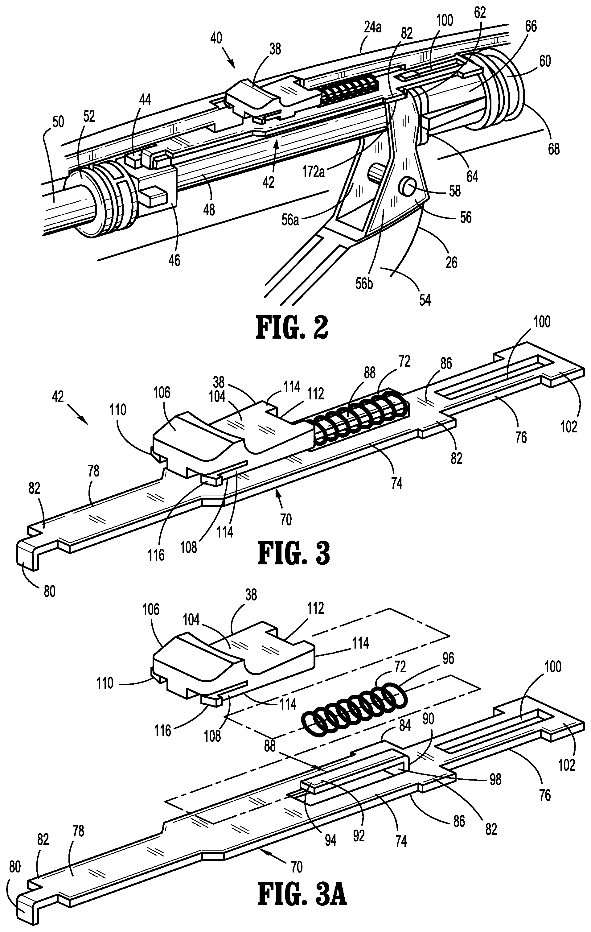
FIG. 2 is a perspective view of a body portion of the surgical stapling device with half of a handle housing removed and showing a lockout assembly;
FIG. 3 is a perspective view of the lockout assembly;
FIG. 3A is a perspective view, with parts separated, of the lockout assembly of FIG. 3;
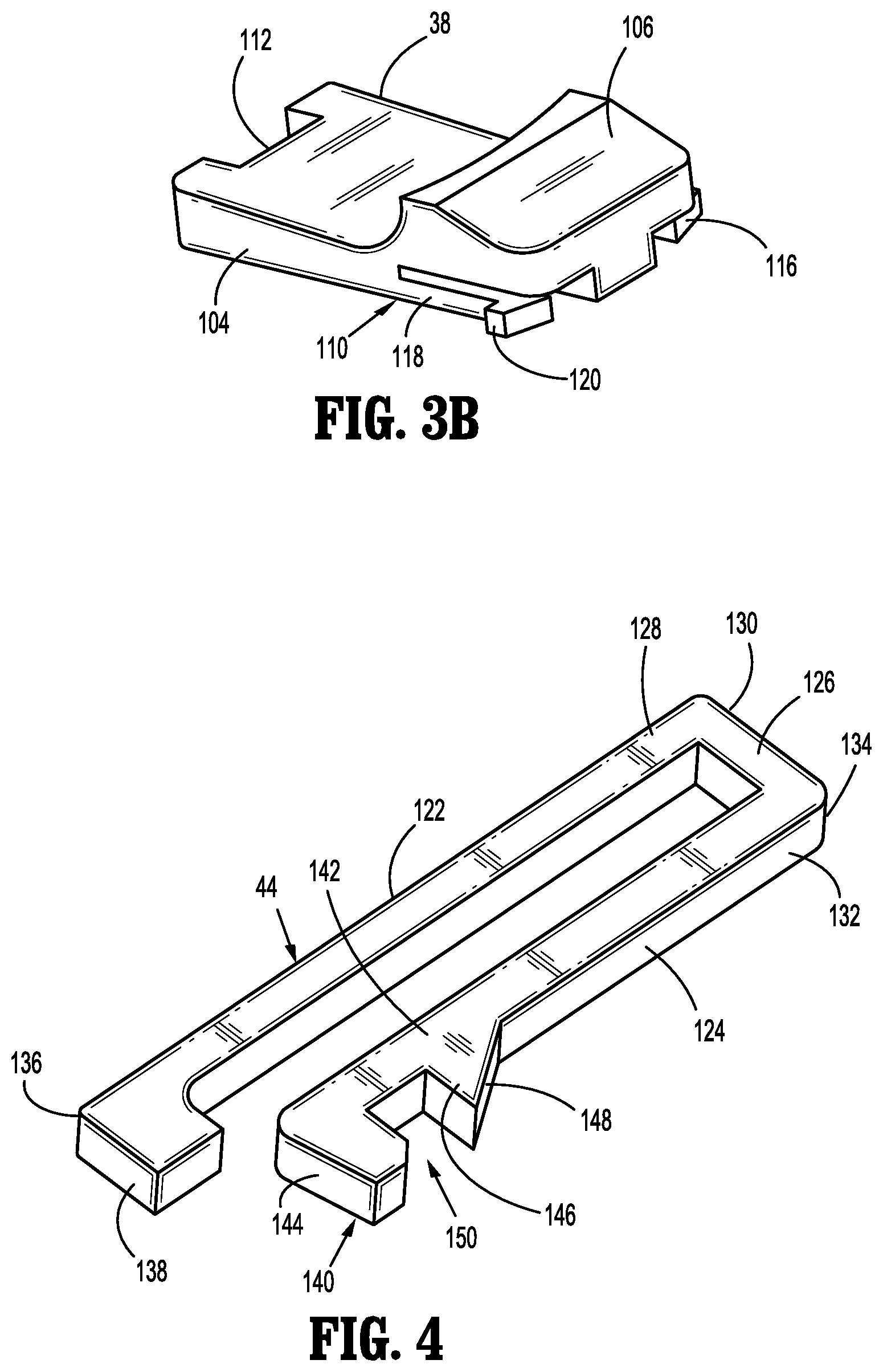
FIG. 3B is a perspective view of the safety button;
FIG. 4 is a perspective view of a secondary lockout member;
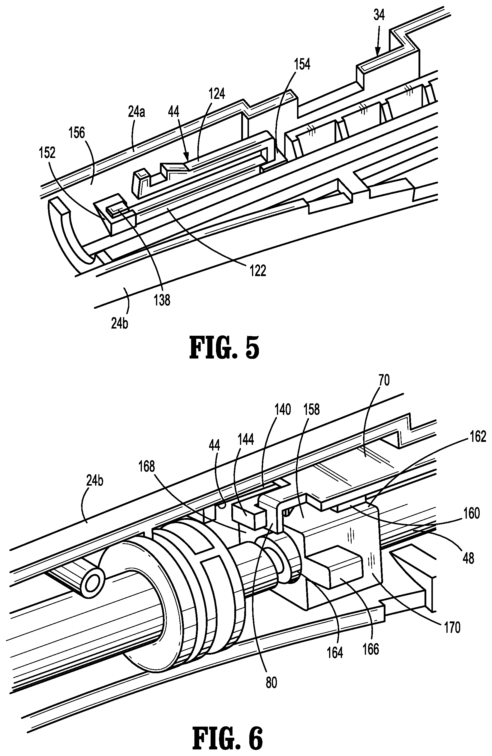
FIG. 5 is a perspective view of the secondary lockout member positioned within channel in a handle housing half;
FIG. 6 is a perspective view the handle housing half with a tab of a slider of the lockout assembly engaged with the secondary lockout member;
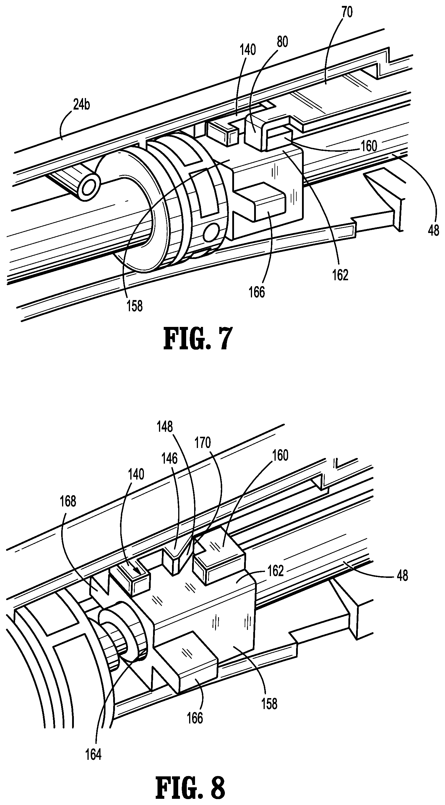
FIG. 7 is a perspective view similar to FIG. 6 with the secondary lockout member disengaged from the slider;
FIG. 8 is a perspective view of the a block, movable within the handle housing, engaging the secondary lockout member;
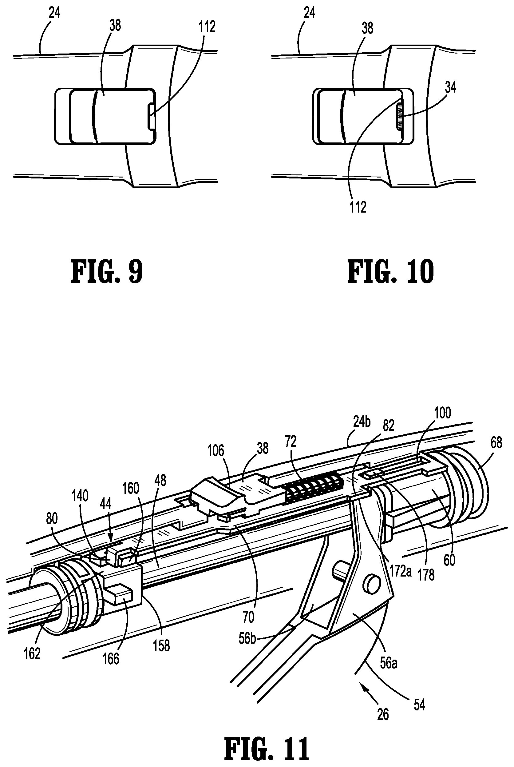
FIG. 9 is a top plan view of a portion of the handle housing showing a safety button;
FIG. 10 is a top plan view, similar to FIG. 9, showing the safety button moved relative to the housing to reveal an indicator portion of the safety button;
FIG. 11 is a perspective view of the body portion of the surgical stapling device with half the handle housing removed and a trigger of the body portion blocked by the slider of the lockout assembly;
FIG. 12 is perspective view similar to FIG. 11, with the slider of the lockout assembly moved to release the trigger for actuation;
FIG. 13 is a top plan view of the safety button positioned within a window of the body portion and engaged in a locked position with the body portion; and
FIG. 14 is a perspective view of the trigger of the surgical stapling device engaging and driving a pusher of the surgical stapling device to fire the surgical stapling device.
DETAILED DESCRIPTION OF EMBODIMENTS
An embodiment of the presently disclosed surgical stapling device will now be described in detail with reference to the drawings wherein like numerals designate identical or corresponding elements in each of the several views. As is common in the art, the term "proximal" refers to that part or component closer to the user or operator, i.e. surgeon or physician, while the term "distal" refers to that part or component further away from the user.
Referring initially to FIG. 1, there is disclosed a surgical stapling device 10 for use in hemorrhoidal surgery. Surgical stapling device 10 generally includes a handle assembly 12 and an elongated body portion 14 having an elongated outer tube 16 and a distal head portion 18.
Distal head portion 18 includes an anvil assembly 20 and a shell assembly 22 which are provided to approximate and staple tissues captured therebetween. While not specifically shown, anvil assembly 20 includes an anvil head containing staple clinching pockets and an anvil shaft for removable connection to elongated body portion 14. Likewise, while not specifically shown, shell assembly 22 includes a plurality of staples and pushers designed to drive the staples out of shell assembly 22, through tissue and into the staple clinching pockets of anvil assembly 20 in a manner commonly known in the art.
Handle assembly 12 generally includes a stationary handle housing 24 extending proximally from elongated body portion 14, a movable or firing trigger 26 pivotally mounted to handle housing 24 and a rotatable approximation knob 28 positioned on a proximal end 30 of handle housing 24. Actuation of rotatable approximation knob 28 functions to move anvil assembly 20 relative to shell assembly 22 to capture tissue therebetween as is known in the art. See, e.g., U.S. Pat. No. 7,303,106 to Milliman et al. ("the '106 patent") which is incorporated herein by reference in its entirety. In embodiments, an external, manually actuated trigger latch 32 is pivotally mounted on handle housing 24 and engagable with firing trigger 26 to block movement of firing trigger 26. Handle housing 24 is formed as two joined handle housing halves 24a and 24b. In the presently disclosed stapling device 10, the trigger latch 32 is optional and can be discarded.
Surgical stapling device 10 additionally includes an indicator 34 that is, visible through a window 36 formed in handle housing 24, and provides a visual indication of the degree of approximation of the anvil assembly 20 relative to shell assembly 22. A safety button or switch 38 is movable within window 36 and is associated with an auto-lock safety mechanism 40 described in more detail hereinbelow.
Referring now to FIGS. 2-7, and initially with regard to FIGS. 2-3A, the auto-lock safety mechanism 40 includes switch 38, a primary lock or slider assembly 42 movably mounted within handle housing 24, a secondary lock or stopper 44 (FIG. 4) mounted in handle housing 24 and a cam member or block 46 which is affixed to a screw shaft assembly 48. The screw shaft assembly 48 is operably engaged with the approximation knob 28 at its proximal end (FIG. 1) and to the anvil assembly 20 at its distal such that the approximation knob 28 is actuable to move the anvil assembly 20 in relation to the shall assembly 22 as described below.
With specific reference to FIG. 2, screw shaft assembly 48 extends through an extension knob tube 50. The extension knob tube 50 supports a collar 52 that is rotatably mounted within the handle housing 24 and is connected to the approximation knob 28. As is known in the art (see the '106 patent), a proximal end of screw shaft assembly 48 includes a helical groove which receives a pin or projection (not shown) provided in the collar 52. Rotation of approximation knob 28, and thus extension knob tube 50 and collar 52, moves the pin within the helical groove in screw shaft assembly 48 to move screw shaft assembly 48 within the housing 24 proximally and distally relative to shell assembly 22.
Firing trigger 26 includes a lever 54 and an upright arm 56 that extends into the handle housing 24. Upright arm 56 may be formed as a pair of spaced upright arms 56a and 56b. A pivot pin 58 extends through upright arm 56 and is mounted to the handle housing 24 to allow firing trigger 26 to pivot relative to handle housing 24. An elongate, cylindrical pusher 60 extends through outer tube 16 (FIG. 1) from firing trigger 26 to shell assembly 22. Movement of firing trigger 26 toward handle housing 24 causes a distal edge 62 of each upright arm 56a, 56b to engage and drive a flange 64, located at a proximal end 66 of cylindrical pusher 60, distally to drive pusher 60 distally. As pusher 60 is driven distally within outer tube 16, a distal end (not shown) of pusher 60 drives the staples out of shell assembly 22 and into the staple clinching pockets of anvil assembly 20 to staple tissue captured between the shell assembly 22 and the anvil assembly 20. A coil spring 68 is provided around cylindrical pusher 60 between an inner wall of housing 24 and a surface of pusher 60 to bias the pusher 60 proximally within handle housing 24 and elongated outer tube 16. Biasing pusher 60 proximally, via engagement of flange 64 with arms 56a, 56b, urges firing trigger 26 towards the unfired position away from handle housing 24.
Referring now to FIGS. 3 and 3A, slider assembly 42 of auto-lock safety mechanism 40 is provided to initially block movement of firing trigger 26 until manually released and thereafter, automatically re-block firing trigger 26 after firing of the stapling device 10. This provides a higher degree of safety as compared to a manually actuated latch 32 which requires manual operation to reengage safety latch 32 after actuating the firing trigger 26. In addition to switch 38, slider assembly 42 includes a slider 70 and a spring 72 mounted on slider 70 which biases the slider 70 distally within handle housing 24 as will be discussed in further detail below. Slider 70 can be formed of sheet metal and includes a central body portion 74, a distal body portion 76 extending distally from central body portion 74 and a proximal body portion 78 extending proximally from central body portion 74. A downwardly depending arm or tab 80 extends from a proximal end of proximal body portion 78 and is received within secondary lock or stopper 44 (FIG. 2) as discussed in detail below to prevent movement of slider 70 within handle housing 24.
Central body portion 74 includes a pair laterally extending arms or trigger blocks 82, 84 at a distal end 86 of central body portion 74. Trigger blocks 82, 84 are positioned to engage flat surfaces 172a formed on upright arms 56a and 56b, respectively of firing trigger 26 to prevent movement of firing trigger 26 as described in more detail hereinbelow (see FIG. 14). Central body portion 74 additionally includes a proximally extending L-shaped mount 88 for fixedly supporting the switch 38 and a coil spring 72. The switch 38 can be fixedly secured to the slider 70 using any known fastening technique including gluing, welding, overmolding, etc. Mount 88 extends proximally along a centerline of central body portion 74 and includes an upright bar 90 and a longitudinal, proximally extending arm 92 extending from upright bar 90. Coil spring 72 is movably mounted over arm 92 and switch 38 is affixed to a proximal end 94 of arm 92. The coil spring 72 abuts a proximal side 98 of upright bar 90 and an inner surface (not shown) of the handle housing 24 to bias slider 70 and switch 38 distally within handle housing 24.
An elongate slot 100 extends longitudinally through distal body portion 76 from distal end 86 of central body portion 74 to a distal end 102 of distal body portion 76. Elongate slot 100 receives a protrusion 178 formed on pusher 60 such that when the pusher 60 is moved distally by the firing trigger 26, the slider 70 is pulled distally to disengage switch 38 from handle housing 24 in a manner described in detail below.
Switch 38 is affixed to mount 88 of slider 70 and includes a body portion 104 having an upwardly projecting distal finger tab 106 and a pair of distally extending latches 108, 110 extending from body portion 104 beneath finger tab 106. A notch 112 is formed in body portion 106. The switch 38 is movable to reposition the notch 112 to cover or uncover the indicator 34 (FIG. 1).
With specific reference to FIGS. 3-3B, latch 108 of switch 38 includes a flexible arm 114 that extends from body portion 104 and terminates in an outwardly extending tab 116 (FIGS. 3 and 3A). Similarly, latch 110 also includes a flexible arm 118 that extends from body portion 104 and terminates in an outwardly extending tab 120 (FIG. 3B). Tabs 116 and 118 releasably engage handle housing 24 and temporarily hold switch 38, and thus slider 70, in a proximal position to free up firing trigger 26 for actuation as will be described in further detail below.
Referring to FIG. 4, stopper 44 is provided to prevent movement of slider 70 prior to the approximation of anvil assembly 20 with shell assembly 22. Stopper 44 is generally U-shaped and includes a first longitudinal bar 122, a second longitudinal bar 124 and a cross bar 126 flexibly connecting first longitudinal bar 122 to second longitudinal bar 124. Specifically, a distal end 128 of first longitudinal bar 122 is connected to a first end 130 of cross bar 126 and a distal end 132 of second longitudinal bar 124 is connected to a second end 134 of cross bar 126. In embodiments, first longitudinal bar 122, second longitudinal bar 124 and cross bar 126 may be formed integrally from a flexible material such as, for example, spring steel, polymeric materials, etc.
As shown, a proximal end 136 of first longitudinal bar 122 has an inwardly directed portion 138. Second longitudinal bar 124 is shorter than first longitudinal bar 122 and has a catch 140 formed at its proximal end 142. Catch 140 includes an inwardly directed portion 144 formed at proximal end 142 and a cam 146 formed on second longitudinal bar 124 distally of inwardly directed portion 142. Cam 146 has a distally facing, angled cam face 148. Catch 140 defines a gap 150 between inwardly directed portion 144 and cam 146 for receipt of tab 80 of slider 70.
As best shown in FIG. 5, stopper 44 is supported within proximal and distal supports 152 and 154 formed within handle housing 24. The proximal and distal supports 152 and 154 extend inwardly from an inner surface 156 of handle housing half 24b. Specifically, inwardly directed portion 138 of first longitudinal bar 122 is located and frictionally retained within proximal support 152 while distal end 128 of first longitudinal bar 122 and first end 130 of cross bar 126 are frictionally retained within distal support 154. This leaves second longitudinal bar 124 free to flex downwardly relative to first longitudinal bar 122 to facilitate movement of catch 140 into and out of engagement with tab 80 of slider 70 as described in detail below.
Referring now to FIGS. 6-8, in order to move or cam catch 140 out of engagement with tab 80 of slider 70, a block 158 having a projection 160 mounted on a first or upper surface 162 thereof is affixed to screw shaft assembly 48. Specifically, screw shaft assembly 48 passes through a bore 164 (FIG. 8) formed through block 158 and is fixedly secured to block 158 using, for example, a set screw (not shown). Thus, when the screw shaft assembly 48 is translated within the handle housing 24 via actuation of the approximation knob, block 158 translates within handle housing 24 along with screw shaft assembly 48. Block 158 additionally includes a pair of wings 166 and 168 which ride in corresponding channels (not shown) formed within handle housing halves 24a and 24b to guide movement of block 158 within the handle housing 24. As best shown in FIG. 8, projection 160 is generally L-shaped and has a proximal cam edge 170 which is positioned to engage the angled cam face 148 of cam 146 of stopper 44 to urge catch 140 outwardly to disengage tab 80 on slider 70 from the catch 40.
Referring now to FIGS. 1 and 6-15, the operation of auto-lock safety mechanism 40, including slider assembly 42 and stopper 44, will now be described. Referring to FIG. 1, trigger 26 is initially retained in a locked position by the trigger latch 32 which must be manually pivoted to an unlocked position. As noted hereinabove, trigger latch 32 is an optional feature of surgical stapling device 10 and is pivoted away from trigger 26 prior to use.
With reference also to FIG. 6, prior to approximation of the anvil assembly 20 in relation to the cartridge assembly 22, tab 80 of slider 70 is received within catch 140 of stopper 44 and block 158 is in a distal or advanced position with projection 160 of block 158 spaced distally of cam 146 of catch 140 of stopper 44. Engagement of tab 80 within the catch 140 prevents slider 70 from longitudinal movement within handle housing 24. Coil spring 72 (FIG. 11) is under compression and urges the slider 70 in the distal direction.
Referring briefly to FIG. 11, in the initial locked out position, trigger blocks 82 and 84 of slider 70, rest on upper flat surfaces 172a of upright arms 56a and 56b of trigger 26 to prevent pivotal movement of trigger 26. This internally "locks out" trigger 26 from actuation and firing of surgical stapling device 10.
Referring again to FIG. 1, when the anvil assembly 20 is approximated or moved proximally toward shell assembly 22 by rotating approximation knob 28 screw shaft assembly 48 is moved proximally within the handle housing 24. As the screw shaft assembly 48 is moved proximally, the block 158 is moved proximally within the handle housing 24.
Referring again to FIGS. 6-8, block 158 moves from its initial advanced position positioned distally of cam 146 of catch 140, wherein catch 140 of stopper 44 is engaged with tab 80 of slider 70 (FIG. 6), to a second position wherein proximal cam edge 170 of projection 160 on block 158 engages the angled cam face 148 of cam 146. As block 158 moves proximally, angled cam face 148 is moved laterally by proximal cam edge 170 to cam catch 140 of stopper 44 out of engagement with tab 80 on slider 70 (FIGS. 7 and 8). The release of tab 80 of slider 70 from catch 140 of stopper 44 frees up slider assembly 42 to facilitate manual movement of the switch 38 and, thus, slider assembly 42 along handle housing 24.
Referring for the moment to FIGS. 7, and 9-11, as screw shaft assembly 48 including block 158 is drawn proximally, projection 160 of block 158 engages tab 80 of slider 70 and pulls the slider assembly 42 proximally a short distance against the bias of the spring 72. As slider assembly 42 is moved proximally, firing trigger 26 is still locked out from movement by trigger blocks 82 and 84 of slider 70 which still partially engage flats 172a of upright arms 56a and 56b of the trigger 26. Switch 38, which is affixed to slider 70, also moves proximally a short distance. Switch 38 moves from an initial position wherein switch 38 covers indicator 34 (FIG. 9) to second position wherein indicator 34 is visible through notch 112 in switch 38 (FIG. 10). This gives a visual indication to a clinician that the anvil assembly 20 and shell assembly 22 are approximated and confirms that the slider assembly 42 has been released from stopper 44. Surgical stapling device 10 is now properly positioned about the tissues to be stapled.
Referring now to FIGS. 12-13, to release trigger 26 for actuation and firing of surgical stapling device 10, the operator pushes against finger tab 106 of switch 38 to move switch 38, and thus slider 70, proximally within handle housing 24 (FIG. 13). As slider 70 is drawn proximally, coil spring 72 is compressed and trigger blocks 82 and 84 are moved away from upper flat surfaces 172a of upright aims 56a and 56b of trigger 26 to unlock the trigger 26 for pivotal movement (FIG. 12).
As best shown in FIG. 13, when switch 38 is moved to its proximal-most position, the switch 38 and, thus, the slider 70 are retained in this position by tabs 116, 120. More specifically, switch 38 of slider assembly 42 is locked in a proximal most position by the outwardly extending tabs 116, 120 on flexible arms 114, 118 of switch 38 which snap into, notches 174 and 176, respectively, formed in handle housing 24 (FIG. 13) adjacent window 36. Receipt of tabs 116, 120 in notches 174, 176 maintains switch 38, and thus slider assembly 42, in the proximal position to maintain trigger blocks 82, 84 spaced from flat surfaces 172a of aims 56a, 56b, respectively of trigger 26 to maintain trigger 26 in the unlocked position.
As best shown in FIG. 14, in the unlocked position, the firing trigger 26 can be pivoted toward handle housing 24 to advance pusher 60, against the bias of coil spring 68, to fire staples from the shell assembly 22 through tissue and into anvil assembly 20.
Referring to FIG. 14, upon full actuation of trigger 26, primary slider lock assembly 42 is released to automatically re-lock out trigger 26 from a second actuation. More specifically, as pusher 60 is driven to a distal most position by trigger 26, a protrusion 178 formed on pusher 60 rides within elongated slot 100 in slider 70. As the distal most position of pusher 60 is reached and the staples have been formed against the anvil assembly 20, block 178 engages the portion of slider 70 defining a distal end 180 of elongated slot 100 to thereby pull slider 70 distally within handle housing 24. As slider 70 is pulled or forced distally, switch 38 is also forced distally such that the tabs 116 and 120 on flexible arms 114 and 118 of the switch 38 are released from locking notches 174 and 176 adjacent window 36 of handle housing 24. This frees up slider assembly 42 to move distally under the bias of coil spring 72. As the tabs 116 and 120 of switch 38 of slider assembly 42 are released from notches 174 and 176, the slider 70 snaps distally and makes a "click" sound giving an audible indication to the clinician that actuation of the trigger 26 is complete and that the auto-lock safety mechanism 40 of surgical stapling device 10 has been automatically reactivated. It is noted that movement of the switch 38 distally also provides a visual indication to the clinician that actuation of the trigger 26 is complete. Upon release of trigger 26, slider 70 returns to the initial position (FIG. 11) wherein slider 70 once again blocks trigger 26 from pivotal movement to prevent a second actuation of surgical stapling device 10.
It should be noted that, upon rotation of approximation knob 28 to separate anvil assembly 20 from shell assembly 22 and release the now stapled tissues, block 158 is moved distally to draw projection 160 out of engagement with catch 140 of stopper 44. Catch 140 flexes back into engagement with tab 80 on slider 70 to thereby again relock slider assembly 42 from further movement (FIG. 6).
Thus, in this manner, auto-lock safety mechanism 40 of surgical stapling 10 positively re-locks out trigger 26 from a second actuation after firing of surgical stapling device 10.
It will be understood that various modifications may be made to the embodiments disclosed herein. For example, the disclosed coil springs may be replaced with other types of springs, such as, for example, leaf springs, etc. Further, as noted above, the external trigger latch may be omitted. Therefore, the above description should not be construed as limiting, but merely as exemplifications of particular embodiments. Those skilled in the art will envision other modifications within the scope and spirit of the claims appended hereto.
* * * * *
D00000
D00001
D00002
D00003
D00004
D00005
D00006
D00007
D00008
XML
uspto.report is an independent third-party trademark research tool that is not affiliated, endorsed, or sponsored by the United States Patent and Trademark Office (USPTO) or any other governmental organization. The information provided by uspto.report is based on publicly available data at the time of writing and is intended for informational purposes only.
While we strive to provide accurate and up-to-date information, we do not guarantee the accuracy, completeness, reliability, or suitability of the information displayed on this site. The use of this site is at your own risk. Any reliance you place on such information is therefore strictly at your own risk.
All official trademark data, including owner information, should be verified by visiting the official USPTO website at www.uspto.gov. This site is not intended to replace professional legal advice and should not be used as a substitute for consulting with a legal professional who is knowledgeable about trademark law.