Ringless web for repair of heart valves
Speziali , et al. Sep
U.S. patent number 10,765,517 [Application Number 15/765,006] was granted by the patent office on 2020-09-08 for ringless web for repair of heart valves. This patent grant is currently assigned to Neochord, Inc.. The grantee listed for this patent is NeoChord, Inc.. Invention is credited to Dave Blaeser, Giovanni Speziali, John Zentgraf.


View All Diagrams
| United States Patent | 10,765,517 |
| Speziali , et al. | September 8, 2020 |
Ringless web for repair of heart valves
Abstract
A ringless web is configured to repair heart valve function in patients suffering from degenerative mitral valve regurgitation (DMR) or functional mitral valve regurgitation (FMR). In accordance with various embodiments, a ringless web can be anchored at one or more locations below the valve plane in the ventricle, such as at a papillary muscle, and one or more locations above the valve plane, such as in the valve annulus. A tensioning mechanism connecting the ringless web to one or more of the anchors can be used to adjust a tension of the web such that web restrains the leaflet to prevent prolapse by restricting leaflet motion to the coaptation zone and/or promotes natural coaptation of the valve leaflets.
| Inventors: | Speziali; Giovanni (St. Louis Park, MN), Blaeser; Dave (St. Louis Park, MN), Zentgraf; John (St. Louis Park, MN) | ||||||||||
|---|---|---|---|---|---|---|---|---|---|---|---|
| Applicant: |
|
||||||||||
| Assignee: | Neochord, Inc. (St. Louis Park,
MN) |
||||||||||
| Family ID: | 1000005039816 | ||||||||||
| Appl. No.: | 15/765,006 | ||||||||||
| Filed: | October 3, 2016 | ||||||||||
| PCT Filed: | October 03, 2016 | ||||||||||
| PCT No.: | PCT/US2016/055108 | ||||||||||
| 371(c)(1),(2),(4) Date: | March 30, 2018 | ||||||||||
| PCT Pub. No.: | WO2017/059406 | ||||||||||
| PCT Pub. Date: | April 06, 2017 |
Prior Publication Data
| Document Identifier | Publication Date | |
|---|---|---|
| US 20180289483 A1 | Oct 11, 2018 | |
Related U.S. Patent Documents
| Application Number | Filing Date | Patent Number | Issue Date | ||
|---|---|---|---|---|---|
| 62235839 | Oct 1, 2015 | ||||
| Current U.S. Class: | 1/1 |
| Current CPC Class: | A61B 17/06166 (20130101); A61F 2/2466 (20130101); A61F 2/2454 (20130101); A61B 17/00 (20130101); A61F 2/2463 (20130101); A61F 2220/0016 (20130101); A61F 2002/0068 (20130101); A61F 2230/0091 (20130101); A61B 2017/0441 (20130101); A61F 2230/0043 (20130101); A61B 2017/0417 (20130101) |
| Current International Class: | A61F 2/24 (20060101); A61B 17/00 (20060101); A61B 17/06 (20060101); A61B 17/04 (20060101); A61F 2/00 (20060101) |
References Cited [Referenced By]
U.S. Patent Documents
| 2751908 | June 1956 | Wallace |
| 3667474 | June 1972 | Lapkin |
| 3744062 | July 1973 | Parsonnet |
| 3842840 | October 1974 | Schweizer |
| 4258716 | March 1981 | Sutherland |
| 4351345 | September 1982 | Carney |
| 4935027 | June 1990 | Yoon |
| 4957498 | September 1990 | Caspari et al. |
| 4967498 | September 1990 | Caspari |
| 4960424 | October 1990 | Grooters |
| 4967798 | November 1990 | Hammer |
| 4972874 | November 1990 | Jackson |
| 5053013 | October 1991 | Ensminger |
| 5059201 | October 1991 | Asnis |
| 5211650 | May 1993 | Noda |
| 5297536 | March 1994 | Wilk |
| 5304185 | April 1994 | Taylor |
| 5312423 | May 1994 | Rosenbluth |
| 5336229 | August 1994 | Noda |
| 5383877 | January 1995 | Clarke |
| 5431666 | July 1995 | Sauder |
| 5433723 | July 1995 | Lindenberg et al. |
| 5452733 | September 1995 | Sterman |
| 5474519 | December 1995 | Bloomer |
| 5480424 | January 1996 | Cox |
| 5547455 | August 1996 | McKenna |
| 5556411 | September 1996 | Taoda |
| 5571215 | November 1996 | Sterman |
| 5601578 | February 1997 | Murphy |
| 5626607 | May 1997 | Malecki |
| 5653716 | August 1997 | Malo |
| 5665100 | September 1997 | Yoon |
| 5667472 | September 1997 | Finn |
| 5667473 | September 1997 | Finn |
| 5667478 | September 1997 | McFarlin |
| 5693091 | December 1997 | Larson |
| 5725552 | March 1998 | Kotula et al. |
| 5728113 | March 1998 | Sherts |
| 5762458 | June 1998 | Wang |
| 5762613 | June 1998 | Sutton |
| 5766163 | June 1998 | Mueller |
| 5772597 | June 1998 | Goldberger |
| 5772672 | June 1998 | Toy |
| 5785658 | July 1998 | Benaron |
| 5797960 | August 1998 | Stevens |
| 5830231 | November 1998 | Gieges |
| 5839639 | November 1998 | Sauer |
| 5853422 | December 1998 | Huebsch et al. |
| 5897564 | April 1999 | Schulze |
| 5908428 | June 1999 | Scirica |
| 5908429 | June 1999 | Yoon |
| 5919128 | July 1999 | Fitch |
| 5961440 | October 1999 | Schewich |
| 5972004 | October 1999 | Williamson |
| 5972030 | October 1999 | Garrison |
| 5984939 | November 1999 | Yoon |
| 5993466 | November 1999 | Yoon |
| 6022360 | February 2000 | Reimels |
| 6045497 | April 2000 | Schweich |
| 6050936 | April 2000 | Schweich |
| 6053933 | April 2000 | Balazs |
| 6059715 | May 2000 | Schweich |
| 6077214 | June 2000 | Mortier |
| 6117144 | September 2000 | Nobles |
| 6129683 | October 2000 | Sutton |
| 6149660 | November 2000 | Laufer |
| 6152934 | November 2000 | Harper |
| 6162168 | December 2000 | Schweich |
| 6162233 | December 2000 | Williamson |
| 6165119 | December 2000 | Schweich |
| 6165120 | December 2000 | Schweich |
| 6165183 | December 2000 | Kuehn |
| 6178346 | January 2001 | Amundson |
| 6183411 | February 2001 | Mortier |
| 6190357 | February 2001 | Ferrari |
| 6214029 | April 2001 | Thill et al. |
| 6234079 | May 2001 | Chertkow |
| 6234995 | May 2001 | Peacock |
| 6245079 | June 2001 | Nobles |
| 6260552 | July 2001 | Mortier |
| 6261222 | July 2001 | Schweich |
| 6264602 | July 2001 | Mortier |
| 6269819 | August 2001 | Oz |
| 6270508 | August 2001 | Klieman |
| 6283993 | September 2001 | Cosgrove |
| 6312447 | November 2001 | Grimes |
| 6332863 | December 2001 | Schweich |
| 6332864 | December 2001 | Schweich |
| 6332893 | December 2001 | Mortier |
| 6355050 | March 2002 | Andreas |
| 6401720 | June 2002 | Stevens |
| 6402679 | June 2002 | Mortier |
| 6402680 | June 2002 | Mortier |
| 6402781 | June 2002 | Langberg |
| 6406420 | June 2002 | McCarthy |
| 6419626 | July 2002 | Yoon |
| 6436107 | August 2002 | Wang |
| 6443922 | September 2002 | Roberts |
| 6451054 | September 2002 | Stevens |
| 6461366 | October 2002 | Sequin |
| 6508777 | January 2003 | Macoviak |
| 6514194 | February 2003 | Schweich |
| 6533796 | March 2003 | Sauer |
| 6537198 | March 2003 | Vidlund |
| 6537314 | March 2003 | Langberg |
| 6551331 | April 2003 | Nobles |
| 6558416 | May 2003 | Cosgrove |
| 6562052 | May 2003 | Nobles |
| 6564805 | May 2003 | Garrison |
| 6582388 | June 2003 | Coleman |
| 6585727 | July 2003 | Cashman |
| 6589160 | July 2003 | Schweich |
| 6602288 | August 2003 | Cosgrove |
| 6616684 | September 2003 | Vidlund |
| 6619291 | September 2003 | Hlavka |
| 6622730 | September 2003 | Ekvall |
| 6626917 | September 2003 | Craig |
| 6626930 | September 2003 | Allen |
| 6629534 | October 2003 | Deem |
| 6629921 | October 2003 | Schweich |
| 6629984 | October 2003 | Chan |
| 6645205 | November 2003 | Ginn |
| 6679268 | January 2004 | Stevens |
| 6692605 | February 2004 | Kerr et al. |
| 6695866 | February 2004 | Kuehn |
| 6709456 | March 2004 | Langberg |
| 6718985 | April 2004 | Hlavka |
| 6723038 | April 2004 | Schroeder |
| 6726648 | April 2004 | Kaplon et al. |
| 6733509 | May 2004 | Nobles |
| 6740107 | May 2004 | Loeb |
| 6746471 | June 2004 | Mortier |
| 6752713 | June 2004 | Johnsons |
| 6752813 | June 2004 | Goldfarb |
| 6755777 | June 2004 | Schweich |
| 6764510 | July 2004 | Vidlund |
| 6770083 | August 2004 | Seguin |
| 6770084 | August 2004 | Bain |
| 6793618 | September 2004 | Schweich |
| 6802860 | October 2004 | Cosgrove |
| 6808488 | October 2004 | Mortier |
| 6810882 | November 2004 | Langberg |
| 6840246 | January 2005 | Downing |
| 6858003 | February 2005 | Evans |
| 6875224 | April 2005 | Grimes |
| 6893448 | May 2005 | O'Quinn |
| 6908424 | June 2005 | Mortier |
| 6918917 | July 2005 | Nguyen |
| 6921407 | July 2005 | Nguyen |
| 6929715 | August 2005 | Fladda |
| 6936054 | August 2005 | Chu |
| 6955175 | October 2005 | Stevens |
| 6962605 | November 2005 | Cosgrove |
| 6978176 | December 2005 | Lattouf |
| 6986775 | January 2006 | Morales |
| 6989028 | January 2006 | Lashinski |
| 6991635 | January 2006 | Takamoto |
| 6997950 | February 2006 | Chawla |
| 7004176 | February 2006 | Lau |
| 7004952 | February 2006 | Nobles |
| 7011669 | March 2006 | Kimblad |
| 7044905 | May 2006 | Vidlund |
| 7048754 | May 2006 | Martin |
| 7070618 | July 2006 | Streeter |
| 7077862 | July 2006 | Vidlund |
| 7083628 | August 2006 | Bachman |
| 7083638 | August 2006 | Foerster |
| 7090686 | August 2006 | Nobles |
| 7094244 | August 2006 | Schreck |
| 7100614 | September 2006 | Stevens |
| 7112207 | September 2006 | Allen |
| 7112219 | September 2006 | Vidlund |
| 7118583 | October 2006 | O'Quinn |
| 7122040 | October 2006 | Hill |
| 7160322 | January 2007 | Gabbay |
| 7179291 | February 2007 | Rourke |
| 7186264 | March 2007 | Liddicoat |
| 7189199 | March 2007 | McCarthy |
| 7217240 | May 2007 | Snow |
| 7226467 | June 2007 | Lucatero |
| 7247134 | July 2007 | Vidlund |
| 7250028 | July 2007 | Julian |
| 7288097 | October 2007 | Seguin |
| 7294148 | November 2007 | McCarthy |
| 7381210 | June 2008 | Zarbatany |
| 7464712 | December 2008 | Oz |
| 7563267 | July 2009 | Goldfarb |
| 7563273 | July 2009 | Oz |
| 7604646 | October 2009 | Goldfarb |
| 7608091 | October 2009 | Goldfarb |
| 7635386 | December 2009 | Gammie |
| 7666204 | February 2010 | Thornton |
| 7704268 | April 2010 | Chanduszko |
| 7815654 | October 2010 | Chu |
| 7879048 | February 2011 | Bain |
| 7887552 | February 2011 | Bachman |
| 8016882 | September 2011 | Macoviak et al. |
| 8052751 | November 2011 | Aklog et al. |
| 8142494 | March 2012 | Rahdert et al. |
| 8303622 | November 2012 | Alkhatib |
| 8443808 | May 2013 | Brenzel et al. |
| 8465500 | June 2013 | Speziali |
| 8758393 | June 2014 | Zentgraf |
| 8938283 | January 2015 | Zentgraf et al. |
| 9044221 | June 2015 | Zentgraf et al. |
| 9192374 | November 2015 | Zentgraf |
| 2001/0005787 | June 2001 | Oz |
| 2001/0016675 | August 2001 | Mortier |
| 2001/0021872 | September 2001 | Bailey |
| 2002/0013571 | January 2002 | Goldfarb |
| 2002/0029080 | March 2002 | Mortier |
| 2002/0049402 | April 2002 | Peacock |
| 2002/0077524 | June 2002 | Schweich |
| 2002/0169359 | November 2002 | McCarthy |
| 2002/0173694 | November 2002 | Mortier |
| 2002/0183766 | December 2002 | Seguin |
| 2003/0004562 | January 2003 | DiCarlo |
| 2003/0032979 | February 2003 | Mortier |
| 2003/0050529 | March 2003 | Vidlund |
| 2003/0050693 | March 2003 | Quijano |
| 2003/0078600 | April 2003 | O'Quinn |
| 2003/0105519 | June 2003 | Fasol |
| 2003/0130731 | July 2003 | Vidlund |
| 2003/0166992 | September 2003 | Schweich |
| 2003/0167071 | September 2003 | Vidlund |
| 2003/0171641 | September 2003 | Schweich |
| 2003/0181928 | September 2003 | Vidlund |
| 2003/0187457 | October 2003 | Weber |
| 2003/0195529 | October 2003 | Takamoto |
| 2003/0199975 | October 2003 | Gabbay |
| 2004/0003819 | January 2004 | St. Goar |
| 2004/0030382 | February 2004 | St. Goar |
| 2004/0039442 | February 2004 | St. Goar |
| 2004/0044350 | March 2004 | Martin |
| 2004/0044365 | March 2004 | Bachman |
| 2004/0049207 | March 2004 | Goldfarb |
| 2004/0049552 | March 2004 | Motoyama |
| 2004/0087975 | May 2004 | Lucatero |
| 2004/0087978 | May 2004 | Velez et al. |
| 2004/0092962 | May 2004 | Thornton |
| 2004/0097805 | May 2004 | Verard |
| 2004/0116767 | June 2004 | Hermann |
| 2004/0122448 | June 2004 | Levine |
| 2004/0127983 | July 2004 | Mortier |
| 2004/0133063 | July 2004 | McCarthy |
| 2004/0167374 | August 2004 | Schweich |
| 2004/0167539 | August 2004 | Kuehn |
| 2004/0220593 | November 2004 | Greenhalgh |
| 2004/0225300 | November 2004 | Goldfarb |
| 2004/0225304 | November 2004 | Vidlund |
| 2004/0236353 | November 2004 | Bain |
| 2004/0236354 | November 2004 | Seguin |
| 2004/0243229 | December 2004 | Vidlund |
| 2004/0267083 | December 2004 | McCarthy |
| 2005/0004665 | January 2005 | Aklog et al. |
| 2005/0004668 | January 2005 | Aklog et al. |
| 2005/0021055 | January 2005 | Toubia |
| 2005/0021056 | January 2005 | St. Goar |
| 2005/0021057 | January 2005 | St. Goar |
| 2005/0033446 | February 2005 | Deem |
| 2005/0038509 | February 2005 | Ashe |
| 2005/0044365 | February 2005 | Bachman |
| 2005/0049667 | March 2005 | Arbefeuille et al. |
| 2005/0065396 | March 2005 | Mortier |
| 2005/0075723 | April 2005 | Schroeder |
| 2005/0075727 | April 2005 | Wheatley |
| 2005/0101975 | May 2005 | Nguyen |
| 2005/0125011 | June 2005 | Spence |
| 2005/0131277 | June 2005 | Schweich |
| 2005/0131533 | June 2005 | Alfieri |
| 2005/0143620 | June 2005 | Mortier |
| 2005/0148815 | July 2005 | Mortier |
| 2005/0149014 | July 2005 | Hauck |
| 2005/0154402 | July 2005 | Sauer |
| 2005/0165419 | July 2005 | Sauer |
| 2005/0171601 | August 2005 | Cosgrove |
| 2005/0216039 | September 2005 | Lederman |
| 2005/0240202 | October 2005 | Shennib |
| 2005/0251187 | November 2005 | Beane |
| 2006/0020275 | January 2006 | Goldfarb et al. |
| 2006/0036317 | February 2006 | Vidlund |
| 2006/0041306 | February 2006 | Vidlund |
| 2006/0052868 | March 2006 | Mortier |
| 2006/0058871 | March 2006 | Zakay |
| 2006/0074484 | April 2006 | Huber |
| 2006/0074485 | April 2006 | Realyvasquez |
| 2006/0089671 | April 2006 | Goldfarb |
| 2006/0100699 | May 2006 | Vidlund |
| 2006/0127509 | June 2006 | Eckman |
| 2006/0135993 | June 2006 | Seguin |
| 2006/0149123 | July 2006 | Vidlund |
| 2006/0161040 | July 2006 | McCarthy |
| 2006/0161193 | July 2006 | Beane |
| 2006/0184203 | August 2006 | Martin |
| 2006/0195012 | August 2006 | Mortier |
| 2006/0195134 | August 2006 | Crittenden |
| 2006/0195183 | August 2006 | Navia et al. |
| 2006/0241340 | October 2006 | Schroeder |
| 2006/0287657 | December 2006 | Bachman |
| 2007/0002627 | January 2007 | Youn |
| 2007/0027451 | February 2007 | Desinger |
| 2007/0049952 | March 2007 | Weiss |
| 2007/0050022 | March 2007 | Vidlund |
| 2007/0055303 | March 2007 | Vidlund |
| 2007/0088375 | April 2007 | Beane |
| 2007/0100356 | May 2007 | Lucatero |
| 2007/0112244 | May 2007 | McCarthy |
| 2007/0118154 | May 2007 | Crabtree |
| 2007/0118155 | May 2007 | Goldfarb |
| 2007/0129737 | June 2007 | Goldfarb |
| 2007/0179511 | August 2007 | Paolitto |
| 2007/0197858 | August 2007 | Goldfarb |
| 2007/0203391 | August 2007 | Bloom |
| 2007/0232941 | October 2007 | Rabinovich |
| 2007/0239272 | October 2007 | Navia |
| 2007/0265643 | November 2007 | Beane |
| 2007/0299468 | December 2007 | Viola |
| 2008/0027468 | January 2008 | Fenton |
| 2008/0051703 | February 2008 | Thornton |
| 2008/0065011 | March 2008 | Marchand |
| 2008/0065156 | March 2008 | Hauser |
| 2008/0065205 | March 2008 | Nguyen |
| 2008/0091059 | April 2008 | Machold |
| 2008/0091264 | April 2008 | Machold |
| 2008/0097482 | April 2008 | Bain et al. |
| 2008/0097489 | April 2008 | Goldfarb |
| 2008/0167714 | July 2008 | St. Goar |
| 2008/0183194 | July 2008 | Goldfarb |
| 2008/0188873 | August 2008 | Speziali |
| 2008/0195200 | August 2008 | Vidlund |
| 2008/0208006 | August 2008 | Farr |
| 2008/0228223 | September 2008 | Alkhatib |
| 2009/0012354 | January 2009 | Wood |
| 2009/0082857 | March 2009 | Lashinski et al. |
| 2009/0105729 | April 2009 | Zentgraf |
| 2009/0105751 | April 2009 | Zentgraf |
| 2009/0131880 | May 2009 | Speziali |
| 2009/0156995 | June 2009 | Martin |
| 2009/0163934 | June 2009 | Raschdorf |
| 2009/0177274 | July 2009 | Scorsin et al. |
| 2009/0259304 | October 2009 | O'Beirne |
| 2009/0306622 | December 2009 | Machold et al. |
| 2010/0042147 | February 2010 | Janovsky et al. |
| 2010/0174297 | July 2010 | Speziali |
| 2010/0262233 | October 2010 | He |
| 2012/0157760 | June 2012 | Aklog |
| 2012/0197388 | August 2012 | Khairkhahan |
| 2012/0290077 | November 2012 | Aklog et al. |
| 2012/0323313 | December 2012 | Seguin |
| 2013/0023985 | January 2013 | Khairkhahan et al. |
| 2013/0035757 | February 2013 | Zentgraf et al. |
| 2013/0304197 | November 2013 | Buchbinder et al. |
| 2014/0039324 | February 2014 | Speziali |
| 2014/0067054 | March 2014 | Chau |
| 2014/0214159 | July 2014 | Vidlund et al. |
| 20 2004 017888 | May 2005 | DE | |||
| 1039851 | Jul 2005 | EP | |||
| 1637091 | Mar 2006 | EP | |||
| 1408850 | Sep 2009 | EP | |||
| 1998686 | Sep 2009 | EP | |||
| 1845861 | Nov 2009 | EP | |||
| 06142114 | May 1994 | JP | |||
| WO 99/00059 | Jan 1999 | WO | |||
| WO 99/11200 | Mar 1999 | WO | |||
| WO 99/30647 | Jun 1999 | WO | |||
| WO 00/06026 | Feb 2000 | WO | |||
| WO 00/06026 | Feb 2000 | WO | |||
| WO 00/06027 | Feb 2000 | WO | |||
| WO 00/06028 | Feb 2000 | WO | |||
| WO 00/16700 | Mar 2000 | WO | |||
| WO 01/66018 | Sep 2001 | WO | |||
| WO 01/95809 | Dec 2001 | WO | |||
| WO 03/001893 | Jan 2003 | WO | |||
| WO 03/059209 | Jul 2003 | WO | |||
| WO 03/082157 | Oct 2003 | WO | |||
| WO 03/082158 | Oct 2003 | WO | |||
| WO 04/021893 | Mar 2004 | WO | |||
| WO 04/043265 | May 2004 | WO | |||
| WO 05/039428 | May 2005 | WO | |||
| WO 05/094525 | Oct 2005 | WO | |||
| WO 06/012750 | Feb 2006 | WO | |||
| WO 06/032051 | Mar 2006 | WO | |||
| WO 06/065966 | Jun 2006 | WO | |||
| WO 06/078694 | Jul 2006 | WO | |||
| WO 06/116310 | Nov 2006 | WO | |||
| WO 06/127509 | Nov 2006 | WO | |||
| WO 07/002627 | Jan 2007 | WO | |||
| WO 07/027451 | Mar 2007 | WO | |||
| WO 07/062128 | May 2007 | WO | |||
| WO 07/081418 | Jul 2007 | WO | |||
| WO 07/117612 | Oct 2007 | WO | |||
| WO 08/010738 | Jan 2008 | WO | |||
| WO 2008/112237 | Sep 2008 | WO | |||
| WO 09/052528 | Apr 2009 | WO | |||
Other References
|
US 6,197,052 B1, 03/2001, Cosgrove (withdrawn) cited by applicant . PCT International Search Report and Written Opinion for PCT/US2016/055108 dated Jan. 11, 2017, 12 pages. cited by applicant . European Search Report for EP Application No. 11863521.8, dated Nov. 15, 2015, 10 pages. cited by applicant . PCT International Preliminary Report on Patentability for PCT/US2008/080560, dated Apr. 29, 2010, 7 pages. cited by applicant . European Search Report, EP Application No. 08839048.9, dated Sep. 16, 2010, 7 pages. cited by applicant . Port Access System for Mitral Valve Repair Proves Its Value in Study; MedGadget, Jul. 9, 2009 as available at: http://medgadget.com/archives/2009/07port access system for mitral valve repair proves its value in study.html (7 pages). cited by applicant . Interactive CardioVascular and Thoracic Surgery; Abstracts: Supplemental 3 to vol. 7 (Sep. 2008), 52 pages. cited by applicant . International Search Report and Written Opinion, Application No. PCT/US2008/080560, dated Aug. 25, 2009, 13 pages. cited by applicant . International Search Report, Application No. PCT/US2008/080560, dated Aug. 28, 2009, 2 pages. cited by applicant . Extended European Search Report, Application No. EP 06718728.6, dated Nov. 11, 2009, 7 pages. cited by applicant . PCT Search Report and Written Opinion, Application No. PCT/US06/01699, dated May 6, 2008. cited by applicant . Notification of International Search Report and Written Opinion of the International Searching Authority, Application No. PCT/US2011/067884, dated Jul. 30, 2012, 11 pages. cited by applicant . International Preliminary Report on Patentability, Application No. PCT/US2011/067884, dated Jul. 11, 2013, 5 pages. cited by applicant. |
Primary Examiner: Ganesan; Suba
Attorney, Agent or Firm: Patterson Thuente Pedersen, P.A.
Claims
The invention claimed is:
1. A ringless web configured to be implanted into a beating heart of a patient to repair heart valve function, comprising: a web configured to be chronically implanted in the beating heart of the patient without being attached to a ring and shaped and sized to correspond to at least one valve in the heart; one or more ventricular anchors operably connected to the web and configured to be anchored in ventricular tissue in the heart, the web being a flexible material formed of a combination of a solid material and at least one open space therein and capable of conforming to aspects of native valve tissue of the beating heart the web further comprising a solid biocompatible material; one or more atrial anchors operably connected to the web and configured to be anchored in atrial tissue in the heart; and a tensioning mechanism operably connected to at least one of the one or more ventricular anchors and the one or more atrial anchors, the tensioning mechanism configured to enable selective adjustment of a tension of the web with respect to the corresponding anchor such that the web is positioned across a plane of the at least one valve to repair valve function.
2. The ringless web of claim 1, wherein the web comprises an array.
3. The ringless web of claim 2, wherein the array comprises a plurality of struts.
4. The ringless web of claim 3, wherein the struts include: a pair of ventricular struts each configured to extend from at least one of the atrial anchors through a coaptation zone of the valve and to at least one of the ventricular anchors; and one or more cross struts extending between the pair of ventricular struts.
5. The ringless web of claim 4, wherein the one or more cross struts includes at least one cross strut configured to be positioned above a plane of the valve and at least one cross strut configured to be positioned below the plane of the valve.
6. The ringless web of claim 5, wherein the solid biocompatible material is positioned between the cross strut configured to be positioned above the plane of the valve and the cross strut configured to be positioned below the plane of the valve but not positioned in the at least one open space of the web.
7. The ringless web of claim 1, wherein the web comprises a net or a mesh.
8. The ringless web of claim 7, wherein the net or mesh is connected to each of the one or more atrial anchors and each of the one or more ventricular anchors with a suture.
9. The ringless web of claim 1, wherein the tensioning mechanism comprises one or more sutures.
10. The ringless web of claim 1, wherein the web repairs valve function by restricting motion of at least one leaflet of the valve to prevent leaflet prolapse.
11. The ringless web of claim 1, wherein each of the one or more ventricular anchors has a different configuration from each of the one or more atrial anchors.
12. A ringless web configured to be implanted into a beating heart of a patient to repair heart valve function, comprising: a web configured to be chronically implanted in the beating heart of the patient without being attached to a ring and shaped and sized to correspond to at least one valve in the heart, the web being a flexible material formed of a combination of a solid material and at least one open space therein and capable of conforming to aspects of native valve tissue of the beating heart the web further comprising a solid biocompatible material; wherein the solid biocompatible material is located below the at least one open space of the web; one or more ventricular anchors operably connected to the web and configured to be anchored in ventricular tissue in the heart; and one or more atrial anchors operably connected to the web and configured to be anchored in atrial tissue in the heart.
13. The ringless web of claim 12, wherein the web comprises an array.
14. The ringless web of claim 13, wherein the array comprises a plurality of struts.
15. The ringless web of claim 14, wherein the struts include: a pair of ventricular struts each configured to extend from at least one of the atrial anchors through a coaptation zone of the valve and to at least one of the ventricular anchors; and one or more cross struts extending between the pair of ventricular struts.
16. The ringless web of claim 15, wherein the one or more cross struts includes at least one cross strut configured to be positioned above a plane of the valve and at least one cross strut configured to be positioned below the plane of the valve.
17. The ringless web of claim 16, wherein the solid biocompatible material is positioned between the cross strut configured to be positioned above the plane of the valve and the cross strut configured to be positioned below the plane of the valve but not positioned in the at least one open space of the web.
18. The ringless web of claim 12, wherein the web comprises a net or a mesh.
19. The ringless web of claim 18, wherein the net or mesh is connected to each of the one or more atrial anchors and each of the one or more ventricular anchors with a suture.
20. The ringless web of claim 12, wherein the web comprises a mesh.
21. The ringless web of claim 20, wherein the mesh is connected to each of the one or more atrial anchors and each of the one or more ventricular anchors with a suture.
22. The ringless web of claim 12, wherein each of the one or more ventricular anchors has a different configuration from each of the one or more atrial anchors.
Description
FIELD OF THE INVENTION
The present invention relates to minimally invasive repair of a heart valve. More particularly, the present invention relates to ringless webs for insertion into a beating heart of a patient to repair a heart valve.
BACKGROUND OF THE INVENTION
Various types of surgical procedures are currently performed to investigate, diagnose, and treat diseases of the heart. Such procedures include repair and replacement of mitral, aortic, and other heart valves, repair of atrial and ventricular septal defects, pulmonary thrombectomy, treatment of aneurysms, electrophysiological mapping and ablation of the myocardium, and other procedures in which interventional devices are introduced into the interior of the heart or vessels of the heart.
Of particular interest are intracardiac procedures for surgical treatment of heart valves, especially the mitral and aortic valves. Tens of thousands of patients are diagnosed with aortic and mitral valve disease each year. Various surgical techniques may be used to repair a diseased or damaged valve, including annuloplasty (contracting the valve annulus), quadrangular resection (narrowing the valve leaflets), commissurotomy (cutting the valve commissures to separate the valve leaflets), shortening mitral or tricuspid valve chordae tendonae, reattachment of severed mitral or tricuspid valve chordae tendonae or papillary muscle tissue, and decalcification of valve and annulus tissue. Alternatively, the valve may be replaced by excising the valve leaflets of the natural valve and securing a replacement valve in the valve position, usually by suturing the replacement valve to the natural valve annulus. Various types of replacement valves are in current use, including mechanical and biological prostheses, homografts, and allografts. Valve replacement, however, can present a number of difficulties including that the invasiveness of the procedure can lead to long recovery times and that the irregular shape of the valve annulus can cause difficulty in properly fixing and orienting the replacement valve, which can lead to leaks and other problems. Therefore, in situations where patients can adequately be treating by repairing, rather than replacing, the valve, it is generally preferable to do so.
The mitral and tricuspid valves inside the human heart include an orifice (annulus), two (for the mitral) or three (for the tricuspid) leaflets and a subvalvular apparatus. The subvalvular apparatus includes multiple chordae tendineae, which connect the mobile valve leaflets to muscular structures (papillary muscles) inside the ventricles. Rupture or elongation of the chordae tendineae, commonly known as degenerative mitral valve regurgitation (DMR), results in partial or generalized leaflet prolapse, which causes mitral (or tricuspid) valve regurgitation. Patients can also suffer from functional mitral valve regurgitation (FMR), in which the chordae, leaflets, and papillary muscles are healthy, but the leaflets still do not properly coapt, causing blood to flow back into the atrium. FMR generally results from left ventricular dilation, which displaces the papillary muscles and stretches the valve annulus.
A number of approaches and devices have been employed to treat leaflet prolapse and/or mitral valve regurgitation. One commonly used technique to surgically correct mitral valve regurgitation is the implantation of artificial chordae (usually 4-0 or 5-0 Gore-Tex sutures) between the prolapsing segment of the leaflet of the valve and the papillary muscle. Another technique involves coapting leaflets together with a clip device and/or suture to prevent leaflet prolapse. Other repair devices, such as spacers and balloons, have been used to provide device-assisted leaflet coaptation to prevent mitral valve regurgitation. However, to date, no specific technique for valve repair has achieved general, broad acceptance in the field as the preferred repair method.
Recent cardiac surgery publications acknowledge the improved patient outcomes delivered with mitral valve repair as compared to mitral valve replacement. One of the factors cited for improved outcomes with mitral valve repair is the preservation of the native mitral valve anatomy. While multiple new technologies are being developed, these technologies are directed towards a target patient population that is very high risk having FMR. It would therefore be desirable to provide for improved valve repair that can be used for patients suffering from DMR as well as patients suffering from FMR.
SUMMARY OF THE INVENTION
A ringless web is configured to repair heart valve function in patients suffering from degenerative mitral valve regurgitation (DMR) or functional mitral valve regurgitation (FMR). In accordance with various embodiments, a ringless web can be anchored at one or more locations below the valve plane in the ventricle, such as at a papillary muscle, and one or more locations above the valve plane, such as in the valve annulus. A tensioning mechanism connecting the ringless web to one or more of the anchors can be used to adjust a tension of the web such that web restrains the leaflet to prevent prolapse by restricting leaflet motion to the coaptation zone and/or promotes natural coaptation of the valve leaflets.
In one embodiment, a ringless web is configured to be chronically implanted into a beating heart of a patient to repair heart valve function. Ringless web can include a web for chronic implantation in the beating heart that is shaped and sized to correspond to at least one valve in the heart. One or more ventricular anchors can be operably connected to the web and configured to be anchored in ventricular tissue in the heart. One or more atrial anchors can be operably connected to the web and configured to be anchored in atrial tissue in the heart. In some embodiments, a tensioning mechanism can be operably connected to one or more of the ventricular anchors and/or one or more of the atrial anchors. The tensioning mechanism can be configured to enable selective adjustment of a tension of the web with respect to the corresponding anchor such that the web is positioned across a plane of the at least one valve to repair valve function. In various embodiments, the web can be formed by, for example, an array, a net or a mesh.
Various embodiments of systems, devices and methods have been described herein. These embodiments are given only by way of example and are not intended to limit the scope of the present invention. It should be appreciated, moreover, that the various features of the embodiments that have been described may be combined in various ways to produce numerous additional embodiments. Moreover, while various materials, dimensions, shapes, implantation locations, etc. have been described for use with disclosed embodiments, others besides those disclosed may be utilized without exceeding the scope of the invention.
BRIEF DESCRIPTION OF THE DRAWINGS
The invention may be more completely understood in consideration of the following detailed description of various embodiments of the invention in connection with the accompanying drawings, in which:
FIG. 1 is a schematic cross-sectional view of a heart;
FIG. 2 is a schematic top plan view of a mitral valve;
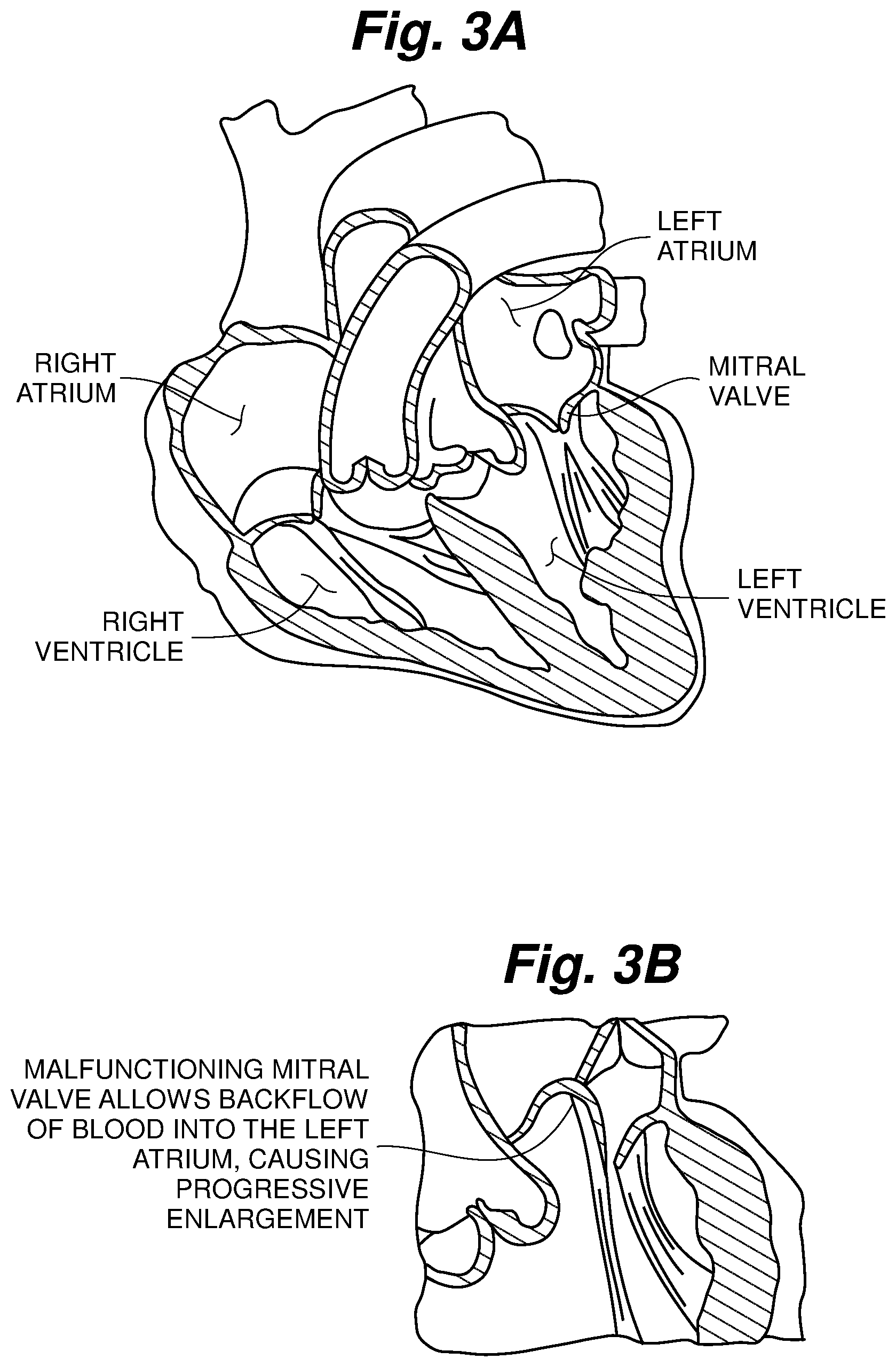
FIG. 3A is a schematic cross-sectional view of a heart with a normal mitral valve;
FIG. 3B is a partial schematic cross-sectional view of a heart with an abnormal mitral valve;
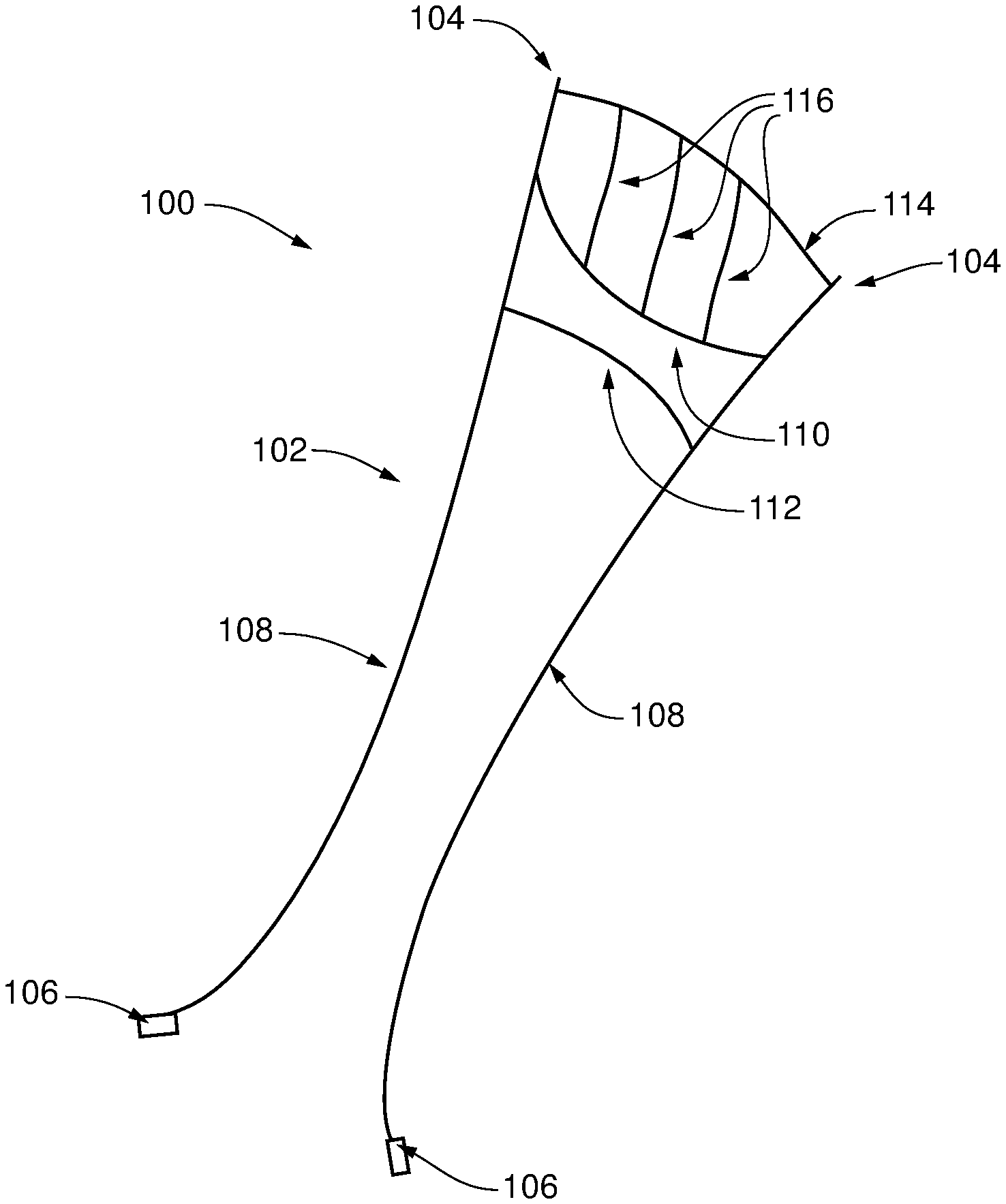
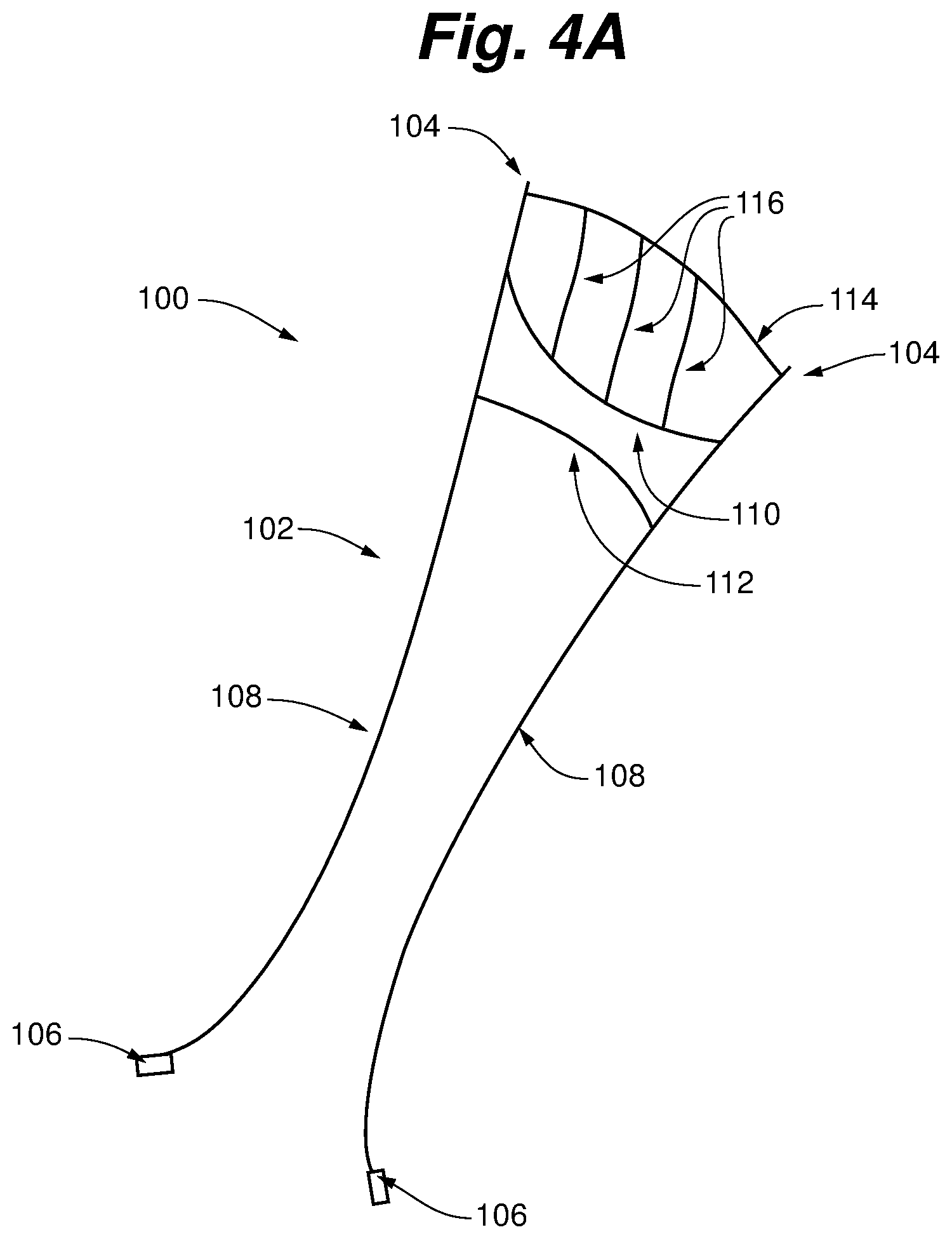
FIG. 4A is a ringless web according to an embodiment of the present invention;
FIG. 4B is a side view of the ringless web of FIG. 4A;
FIGS. 5A and 5B are schematic representations of the ringless web of FIGS. 4A and 4B deployed in the heart.
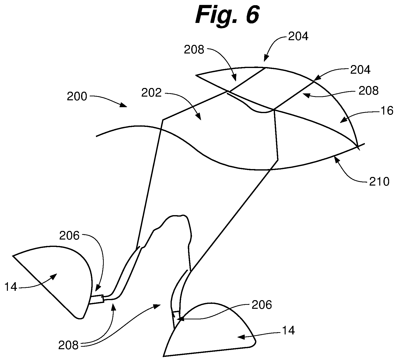
FIG. 6 is a schematic representation of a ringless web according to an embodiment of the present invention deployed in the heart.
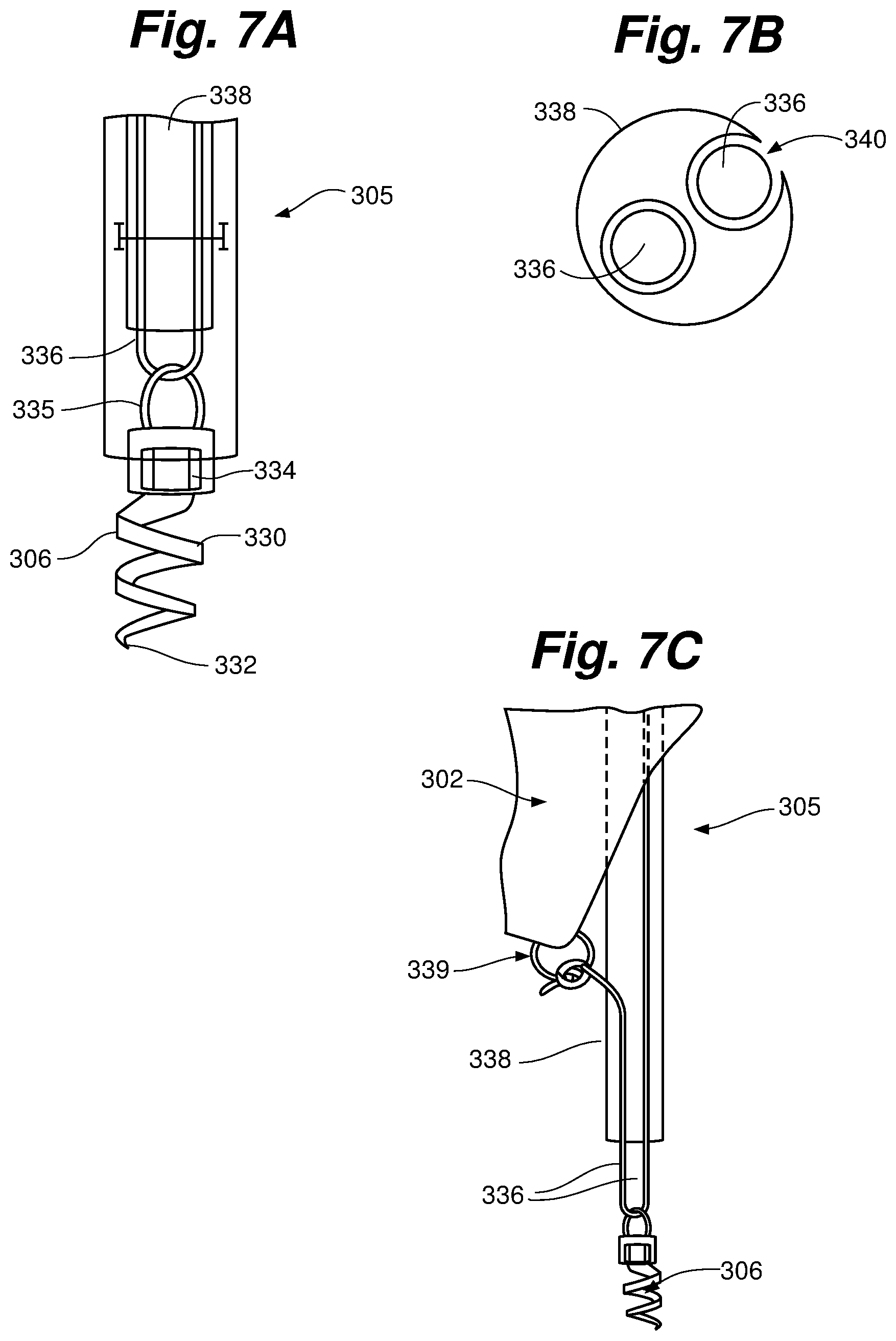
FIGS. 7A-7C depict an anchor system for a ringless web according to an embodiment of the present invention.
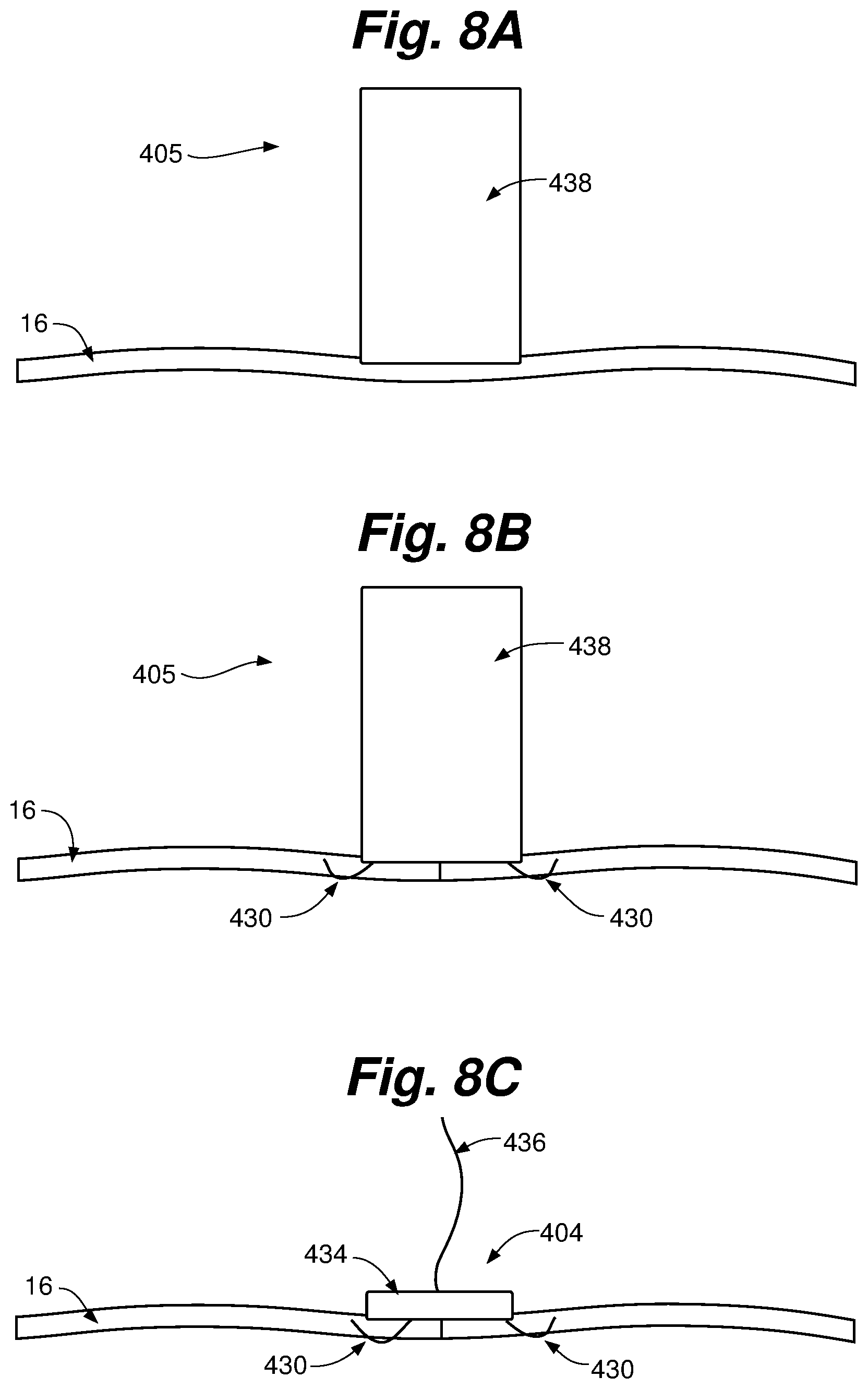
FIGS. 8A-8C depict an anchor system for a ringless web according to an embodiment of the present invention.
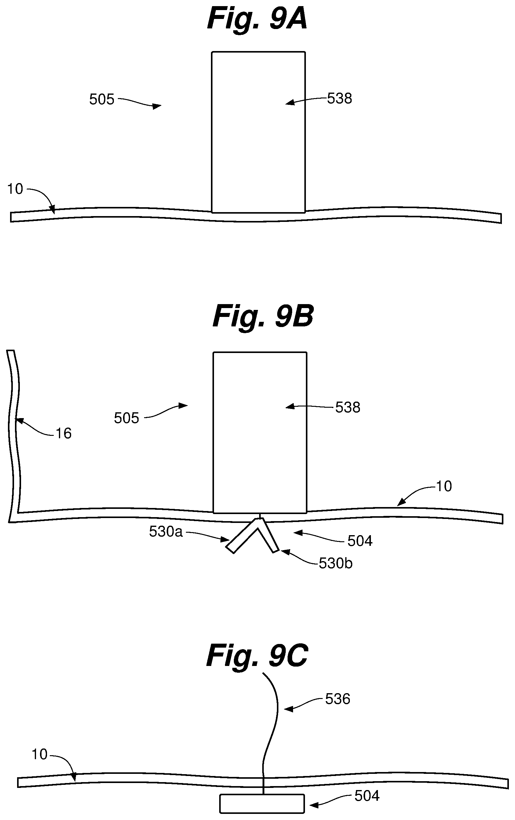
FIGS. 9A-9C depict an anchor system for a ringless web according to an embodiment of the present invention.
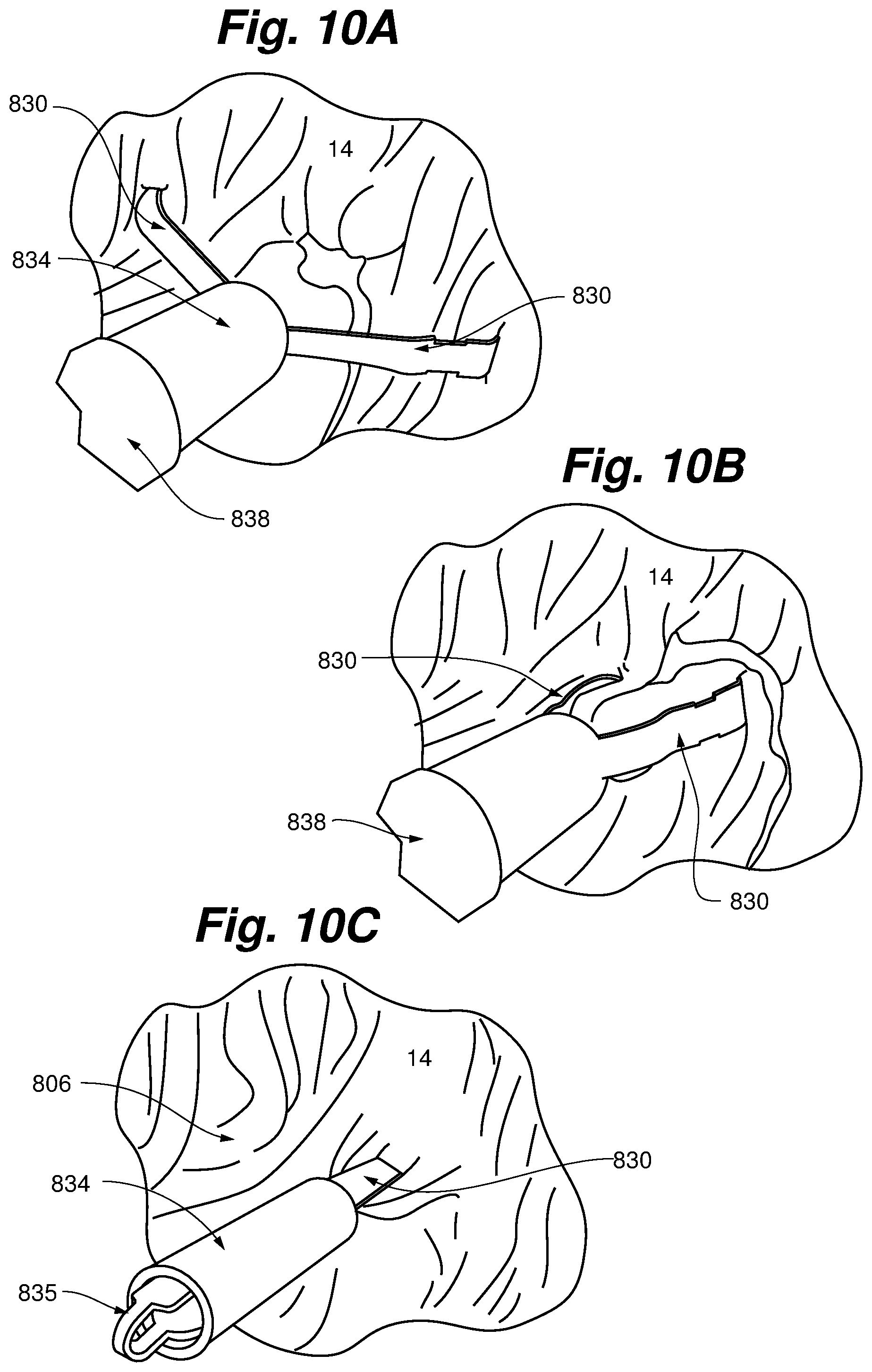
FIGS. 10A-10C depict an anchor for a ringless web according to an embodiment of the present invention.
FIG. 11 is a schematic representation of a heart valve repair device according to an embodiment of the present invention deployed in the heart.
FIG. 12 is flowchart depicting a procedure for positioning a ringless web in the heart according to an embodiment of the present invention.
FIGS. 13A-13C depict a heart valve repair device according to an alternative embodiment.
While the invention is amenable to various modifications and alternative forms, specifics thereof have been shown by way of example in the drawings and will be described in detail. It should be understood, however, that the intention is not to limit the invention to the particular embodiments described. On the contrary, the intention is to cover all modifications, equivalents, and alternatives falling within the spirit and scope of the invention.
DETAILED DESCRIPTION
A mitral valve is schematically depicted in FIGS. 1-3B. Situated between the left atrium and left ventricle, the mitral valve consists of two flaps of tissue, or leaflets (a posterior leaflet and an anterior leaflet). The mitral valve annulus forms a ring around the valve leaflets, thereby connecting the leaflets to the heart muscle. Papillary muscles are located at the base of the left ventricle. Tendon-like cords called chordae tendineae anchor the mitral valve leaflets to the papillary muscles. Normal chordae tendineae prevent the leaflets from prolapsing, or inverting, into the left atrium, as depicted in FIG. 3A.
Under normal cardiac conditions, the left atrium contracts and forces blood through the mitral valve and into the left ventricle. As the left ventricle contracts, hemodynamic pressure forces the mitral valve shut and blood is pumped through the aortic valve into the aorta. For the mitral valve to shut properly, the valvular edges of the valve leaflets must form a non-prolapsing seal, or coaptation, that prevents the backflow of blood during left ventricular contraction.
A properly functioning mitral valve opens and closes fully. When the mitral valve fails to fully close, as depicted in FIG. 3B, blood from the left ventricle is able to flow backward into the left atrium instead of flowing forward into the aorta. This backflow of blood through the heart valve is called regurgitation. The regurgitation of blood through the heart due to the failure of the mitral valve to close properly (coapt) is the condition known as mitral valve regurgitation (MR). A common symptom of mitral valve regurgitation is congestion of blood within the lungs.
When blood regurgitates from the left ventricle into the left atrium, such as due to MR, less blood is pumped into the aorta and throughout the body. In an attempt to pump adequate blood to meet the blood needs of the body, the left ventricle tends to increase in size over time to compensate for this reduced blood flow. Ventricular enlargement, in turn, often leads to compromised contractions of the heart, thereby exacerbating the congestion of blood within the lungs. If left untreated, severe MR can eventually lead to serious cardiac arrhythmia and/or congestive heart failure (CHF).
Mitral valve regurgitation can be caused by any number of conditions, including mitral valve prolapse (a condition in which the leaflets and chordae tendineae of the mitral valve are weakened resulting in prolapse of the valve leaflets, improper closure of the mitral valve, and the backflow of blood within the heart with each contraction of the left ventricle), damaged chords (wherein the chordae tendineae become stretched or ruptured, causing substantial leakage through the mitral valve), ventricular enlargement (FMR), rheumatic fever (the infection can cause the valve leaflets to thicken, limiting the valve's ability to open, or cause scarring of the leaflets, leading to regurgitation), endocarditis (an infection inside the heart), deterioration of the mitral valve with age, prior heart attack (causing damage to the area of the heart muscle that supports the mitral valve), and a variety of congenital heart defects. As MR becomes exacerbated over time, however, the condition can become more severe, resulting in life-threatening complications, including atrial fibrillation (an irregular heart rhythm in which the atria beat chaotically and rapidly, causing blood clots to develop and break loose and potentially result in a stroke), heart arrhythmias, and congestive heart failure (occurring when the heart becomes unable to pump sufficient blood to meet the body's needs due to the strain on the right side of the heart caused by fluid and pressure build-up in the lungs).
The present application describes various devices that can be implanted into the beating heart of a patient in a minimally invasive manner to treat mitral valve regurgitation as described above. Embodiments of the devices described herein can be used to restrain a prolapsing leaflet to prevent leaflet prolapse in patients suffering from DMR and to promote and retrain natural leaflet coaptation in FMR patients with a minimal device form factor that respects the native valve. In various embodiments, the implantable devices may be adaptable to treat both simple and complex repair requirements including small to large prolapsing or flail segments of primary MR patients (DMR) on either the posterior or anterior leaflets of secondary MR (FMR) patients, as will be described herein.
FIGS. 4A and 4B depict one embodiment of a ringless web 100 for treating leaflet prolapse by restraining the leaflet and/or promoting natural coaptation of leaflets according to an embodiment of the present invention. In this embodiment, ringless web 100 comprises an array 102 of intersecting members or struts and multiple anchors that can include one or more atrial anchors 104 and one or more ventricular anchors 106. Array 102 is positioned within the heart to repair the valve and anchors 104 are utilized to maintain the array 102 in the proper position for repair. Web 100 is ringless in that it is secured above the valve plane without being attached to a ring or partial ring seated above the valve plane. Rather, ringless web 100 is anchored in discrete locations above the valve plane via atrial anchors and sutures, as will be described in more detail herein.
As shown in FIGS. 4A and 4B, one embodiment of array 102 can comprise a pair of ventricular struts 108 to extend from anchor points in the atrium above the valve plane, through the coaptation zone of the leaflets and down to anchor points in the left ventricle. Array 102 can also include one or more cross struts, which, in the depicted embodiment, include an upper valve plane strut 110, a lower valve plane strut 112, and an atrial strut 114. In some embodiments, array can further include leaflet struts 116. In some embodiments, a solid biomaterial can be disposed between the upper valve plane strut 110 and lower valve plane strut 112.
The various members or struts of array 102 can be sutures. In various embodiments, struts can be comprised of expanded polytetrafluoroehtylene material or other material suitable for use in the human body. In some embodiments, struts that support the loads applied to the web caused by movement of the leaflets can be comprised of a braided suture material, such as, for example, one or more of the ventricular struts 108, valve plane struts 110, 112, and atrial strut 114. Other struts that contact the leaflets or other valve tissue, such as leaflet struts 116, can be formed of a single suture strand. In some embodiments, struts such as leaflet struts 116 that contact the leaflet or other tissue can have a non-uniform cross-section, such as ovoid, with the portion of the cross-section of greater size positioned to contact the leaflet to distribute the force imparted on the leaflet by the struts to minimize possible damage to the leaflet.
FIGS. 5A and 5B schematically depict ringless web 100 deployed in the heart adjacent a valve leaflet 10, papillary muscles 14, and natural chordae tendinae 12 extending between the valve leaflet 10 and the papillary muscles 14. Leaflet 10 could be either the anterior leaflet or posterior leaflet of the mitral valve, for example. Web 100 can interact with leaflet 10 to restrain the leaflet and restrict leaflet motion to the coaptation zone during systole to prevent the leaflet from prolapsing, which is particularly advantageous in patients suffering from DMR. Atrial anchors 104 are situated in a region above the valve plane in or adjacent to the annulus of the valve. Anchors 104 can be positioned in, for example, the valve annulus, the heart wall adjacent the annulus, or a leaflet adjacent the annulus. Atrial strut 114 can provide support to the web between the atrial anchor 104 points. Ventricular struts 108 extend from the atrial anchors 104, through the valve plane and down into the ventricle where they are anchored with ventricular anchors 106 somewhere in or adjacent to the ventricular wall, such as at the papillary muscles 14. Typically, ventricular anchors 106 are anchored somewhere below a midpoint of the ventricle. In the depicted embodiment, there are two atrial anchors 104 and two ventricular anchors 106, though it should be understood that greater or fewer atrial and/or ventricular anchors can be employed and the numbers of the respective anchors need not be the same. Similarly, the figures depict an embodiment with a pair of ventricular struts 108 that provide redundant support for web, but greater or fewer such struts could be utilized.
As discussed herein, anchoring of the described webs refers to utilization of multiple distinct points of attachment to the wall or muscular structure of the interior chambers of the heart, or, in some embodiments, to a valve leaflet. In some embodiments, one or more anchors are separate devices that are pre-attached to web 100. In other embodiments, one or more anchors can be advanced into the body and utilized to anchor web 100 following deployment of web in the heart. In further embodiments, one or more anchors can be unitarily formed as a single construct with web. Combinations of these embodiments are also contemplated.
As shown in FIGS. 5A and 5B, upper valve plane strut 110 can be positioned above the valve plane and lower valve plane strut 112 can be positioned below the valve plane to offer support on the leaflet and on sub-valvular structure such as the chordae tendinae, respectively, to reduce the load on the ringless web 100 at the atrial anchors 104. Portions of web 100 are therefore positioned both above and below the valve plane. In some embodiments, the region 111 between the valve plane struts 110, 112 that is in the coaptation zone of the leaflets can include a solid biomaterial positioned therein to increase the surface area for leaflet coaptation, which is particularly useful for patients suffering from functional mitral valve regurgitation. In some such embodiments, the use of web 100 in valve to prevent regurgitation ultimately retrains and reshapes the valve such that the valve leaflets and annulus naturally revert to a more natural configuration to obtain proper coaptation over time. In such embodiments, the biomaterial can be a bioabsorbable material that is absorbed into the body over time. Suitable biomaterials can include, for example, bovine pericardium and CardioCel.RTM.. Leaflet struts 116 can be positioned to overlay the leaflet to prevent leaflet prolapse.
FIG. 6 depicts a ringless web 200 according to another embodiment of the present invention deployed in the heart. Ringless web 200 includes a body 202 configured as a dense mesh or net material as opposed to an array of members or struts as described with respect to repair device 100. Similarly to the embodiment described above incorporating a solid biomaterial, web 200 can advantageously be employed to treat patients suffering from FMR. In such cases, the web, which in some embodiments can include or be formed of a bioabsorbable material, can retrain and reshape the valve such that the valve leaflets and annulus naturally revert to a more natural configuration to obtain proper coaptation over time.
Similarly to the previous embodiment, body 202 is positioned within the heart with one or more atrial anchors 204 positioned in or near the valve annulus 16 and one or more ventricular anchors 206 seating in, for example, a papillary muscle 14. Each anchor can be attached to body 202 with one or more sutures 208. Body 202 is positioned to extend across the valve plane 210 through the coaptation zone to provide additional surface area for leaflet coaptation.
As exemplified in the embodiments described herein, ringless webs according to embodiments of the present invention can comprise a variety of different configurations having a variety of different porosities. A "web" as described herein describes a flexible material having a combination of solid material and open space therein and capable of conforming to aspects of the native valve tissue. For example, webs can comprise an array, a net or a mesh, which have decreasing amounts of porosity. In one embodiment, an array can be considered a web having 70-90% open space, a net can 30-75% open space and a mesh can have 10%-30% open space.
FIGS. 7A-7C depict one embodiment of an anchoring system 305 that can be used with the various ringless web embodiments of the present invention. Anchoring system 305 can be used to implant either atrial anchors or ventricular anchors as described herein. Each of the various embodiments of anchoring systems discussed herein can be used interchangeably such that different anchor embodiments can be used for atrial anchors than for ventricular anchors, as well as using atrial anchors that differ from each other and/or ventricular anchors that differ from each other. In one embodiment, anchoring system 305 implants a ventricular anchor 306 into a papillary muscle. Anchoring systems as described herein can include embodiments in which the anchors are independent of the web repair device with an interconnect existing between the web device and the anchors. Alternatively, anchoring systems can be configured such that the anchors are integrated into and unitary with the web repair device.
Anchoring system 305 includes a soft tissue anchor 306 that can include an anchor portion 330 configured as a corkscrew shape having a sharp distal tip 332 and a head 334. A connector 335 can be attached to head 334 of anchor. In some embodiments, connector 335 can be formed by a loop of suture material. Connector 335 can connect anchor 306 to a tensioning suture 336 that can be looped through the connector 335 and carried by a tensioning catheter 338 as shown in FIG. 7A. Tensioning suture 336 can extend from anchor 306 towards a ringless web 300 and be connected thereto, by, for example, being tied by a surgeon with a knot onto a connecting element such as a ring 339. Tensioning catheter includes a longitudinal opening 340 that enables the tension of tensioning suture 336 to be adjusted after anchor portion 330 has been driven into soft tissue, with head 334 and connector 335 extending from tissue. In this manner, when an anchor 306 is implanted into soft tissue, such as a papillary muscle, tensioning suture 336 can be used to adjust the tension with which the anchor carries a ringless web 300 to ensure proper repair. Proper leaflet function with repair device in place at a given tension can be confirmed via, e.g., an ultrasonic imaging system, prior to tying off the tensioning suture. In other embodiments, ringless webs, anchors, and connecting sutures as described herein can be pre-sized to provide proper valve function or can be conformable to the valve such that tensioning of web with respect to anchors is not required.
FIGS. 8A-8C depict another embodiment of an anchoring system 405 that can be used with the various ringless web embodiments of the present invention. Anchoring system 405 can be used to implant either an atrial anchor or a ventricular anchor as described herein. In one embodiment, anchoring system 405 implants an atrial anchor into annular tissue 16.
Anchoring system 405 can include a delivery catheter 438 that delivers an anchor 404 to the target tissue 16. Anchor 404 can include a head 434 and one or more barbs 430 configured to penetrate tissue 16 and retain anchor 404 on tissue 16. A suture 436 can extend from anchor 404 to connect anchor 404 to a ringless web. In operation, delivery catheter 438 is used to forcibly drive barbs 430 of anchor 404 into tissue 16. The delivery catheter 438 is then withdrawn, leaving the anchor 404 in place, with suture 436 attaching the anchor 404 to the ringless web and barbs 430 retaining the anchor 404 in the tissue 16. Although depicted as including a single suture 436, in other embodiments anchor 404 can include a connector and tensioning suture as discussed above to enable selective tensioning of a ringless web with respect to anchor 404.
FIGS. 9A-9C depict another embodiment of an anchoring system 505 that can be used with the various ringless web embodiments of the present invention. As with the above embodiments, anchoring system 505 can be used to implant either an atrial anchor or a ventricular anchor as described herein. In one embodiment, anchoring system 505 implants an atrial anchor 504 into a leaflet 10 near the valve annulus 16. In one embodiment, the anchor can be inserted near the edge of a valve leaflet 10 approximately three millimeters from the annulus 16. Alternatively, an atrial anchoring system 505 could implant an atrial anchor 504 into the annulus 16.
Anchoring system 505 can include a delivery catheter 538 that delivers an anchor 504 to the target tissue 10. Anchor 504 can initially be configured in a generally L-shaped configuration with a first leg 530a and a second leg 530b. This allows delivery catheter 538 used to forcibly drive anchor 504 into and/or through tissue 10. The delivery catheter 538 is then withdrawn, and when tension is applied to suture 536 the anchor 504 bends around the junction between legs 530a, 530b to convert to a linear configuration that embeds the anchor 504 in, or on the opposite side of, tissue 10. Although depicted as including a single suture 536, as with the previous embodiment in other embodiments anchor 504 can include a connector and tensioning suture as discussed above to enable selective tensioning of a ringless web with respect to anchor.
FIGS. 10A-10C depict another embodiment of an anchor 806 that can be used with any of the embodiments of the present invention, and in particular can be used as a ventricular anchor in place of the corkscrew anchor 306 described with respect to FIGS. 7A-7C. Anchor 806 includes a pair of grasping prongs 830 extending from a body 834. A catheter 838 can be used to deliver the anchor 806 to the anchor site, e.g., the papillary muscle, and can actuate the prongs to grasp the tissue 14. When it is determined that the prongs 830 have an adequate grasp on the tissue 14, they can be locked into place and the catheter withdrawn. Anchor 806 can include a connector 835 at a proximal end thereof that can receive a tensioning suture used to tension a ringless web with respect to the anchor 806 as described above.
FIG. 11 schematically depicts a ringless web 600 in a final deployed position in a mitral valve of the heart according to an embodiment of the present invention. Ringless web 600 is anchored with atrial anchors 604 in or adjacent the valve annulus 16. The body 602 extends through the coaptation zone 18 between the anterior valve leaflet 11 and the posterior valve leaflet 13. The body is anchored via sutures 608 connected to ventricular anchors 606 seated in the papillary muscles 14 adjacent the natural chordae 12. Alternatively, body 602 could be anchored to the ventricular wall. By being positioned in this manner and properly tensioned as described herein, body 602 aids in promoting natural leaflet coaptation and/or prevents leaflet prolapse as discussed above. It should be noted that although ringless web 600 is depicted as including a solid body similar to the embodiment described with respect to FIG. 6, a device comprising an array of struts such as described with respect to FIGS. 4A-5B or other configuration as described above would attain a similar final position according to embodiments of the present invention.
FIG. 12 depicts a flowchart of one embodiment of procedural steps 800 taken to deploy a ringless web in the heart according to embodiments of the present invention. After the left side of the heart has been accessed, the ventricular anchors, for example, first and second ventricular anchors are sequentially inserted into heart tissue in the left ventricle at step 802. In some embodiments, a first anchor is inserted into a papillary muscle on a first side of the ventricle and a second anchor is inserted into a papillary muscle on a generally opposing side of the ventricle. At step 804, the web is positioned across the valve plane such that it is partially in the left atrium and partially in the left ventricle. The atrial anchors, for example, first and second atrial anchors, can then be seated in atrial tissue above the valve plane, such as in the valve annulus at step 806. With all four anchors in place and the web extending across the valve, at step 808 the tension placed on web from the sutures extending from one or both of the atrial and ventricular anchors can be adjusted. An ultrasound or other imaging system can then be used to confirm proper heart function and leaflet interaction with the web at the set tension at step 810. When proper heart function is confirmed, the tension can be fixed, such as by tying off the sutures connecting the one or more anchors to the web at step 812. In other embodiments, ringless web may not require tensioning. For example, web and sutures could be pre-sized for proper valve function or conformable to the valve such that the described tensioning steps are not utilized. A similar procedure as described above could be conducted to deploy a ringless web in other valves or regions of the heart.
FIGS. 13A-13C depict a heart valve repair device 700 according to an alternative embodiment. Device 700 includes a generally clamshell shaped body comprising a frame 702, which is depicted in FIG. 11A in a generally open position and in FIG. 11B in a partially-closed, deployed position. A coaptation material 704 can be carried by frame 702. In various embodiments, coaptation material 704 can include, for example, a net structure, a mesh material, an array of individual strand elements, such as sutures, or some combination thereof. When deployed in the heart, an upper portion 706 of the frame 702 sits in the annulus of the valve, with the frame extending through one of the commissures of the valve and around a portion of the valve inferior to the valve plane due to the partially-closed clamshell shape of the frame 702. This causes the coaptation material to overlap a prolapsing segment of either the anterior or posterior leaflet of, e.g., the mitral valve, depending on the manner in which the device 700 is positioned. In some embodiments, the portion of the body located inferior to the valve plane is positioned between the natural chordae of the valve and the ventricular wall. Alternatively, this portion of the frame can be positioned below the coaptation zone of the leaflets, generally in front of the native chordae. In some embodiments, particularly for patients suffering from functional mitral valve regurgitation, the coaptation material could be dense mesh that generally resembles a solid material to increase the surface area for coaptation.
The values noted above are example embodiments and should not be read as limiting the scope of this invention other than as expressly claimed. Those skilled in the art will recognize that the above values may be adjusted to practice the invention as necessary depending on the physical characteristics of the patient.
Although specifically described with respect to the mitral valve, it should be understood the devices described herein could be used to treat any other malfunctioning valve, such as the tricuspid and aortic valves. Further, although not specifically described herein, it should be understood that the devices described in the present application could be implanted into the beating heart of the patient via various access approaches known in the art, including transapical approaches (through the apex of the left ventricle) and transvascular approaches, such as transfemorally (through the femoral vein). One example of a transapical access approach that could be employed with ringless webs as described herein is described in U.S. Pat. No. 9,044,221, which is hereby incorporated by reference herein. One example of a transvascular access approach that could be employed with ringless webs as described herein is described in U.S. Patent Publication No. 2013/0035757, which is hereby incorporated by reference herein. This versatility in access approach enables the access site for the procedure to be tailored to the needs of the patient.
Various embodiments of systems, devices, and methods have been described herein. These embodiments are given only by way of example and are not intended to limit the scope of the present invention. It should be appreciated, moreover, that the various features of the embodiments that have been described may be combined in various ways to produce numerous additional embodiments. Moreover, while various materials, dimensions, shapes, implantation locations, etc have been described for use with disclosed embodiments, others besides those disclosed may be utilized without exceeding the scope of the invention.
* * * * *
References
D00000
D00001
D00002
D00003
D00004
D00005
D00006
D00007
D00008
D00009
D00010
D00011
D00012
D00013
D00014
XML
uspto.report is an independent third-party trademark research tool that is not affiliated, endorsed, or sponsored by the United States Patent and Trademark Office (USPTO) or any other governmental organization. The information provided by uspto.report is based on publicly available data at the time of writing and is intended for informational purposes only.
While we strive to provide accurate and up-to-date information, we do not guarantee the accuracy, completeness, reliability, or suitability of the information displayed on this site. The use of this site is at your own risk. Any reliance you place on such information is therefore strictly at your own risk.
All official trademark data, including owner information, should be verified by visiting the official USPTO website at www.uspto.gov. This site is not intended to replace professional legal advice and should not be used as a substitute for consulting with a legal professional who is knowledgeable about trademark law.