Methods for producing panels using 3D-printed tooling shells
Gunner , et al. Sep
U.S. patent number 10,759,090 [Application Number 15/430,395] was granted by the patent office on 2020-09-01 for methods for producing panels using 3d-printed tooling shells. This patent grant is currently assigned to DIVERGENT TECHNOLOGIES, INC.. The grantee listed for this patent is DIVERGENT TECHNOLOGIES, INC.. Invention is credited to Jon Paul Gunner, Narender Shankar Lakshman.


| United States Patent | 10,759,090 |
| Gunner , et al. | September 1, 2020 |
Methods for producing panels using 3D-printed tooling shells
Abstract
Techniques for producing panels such as for use in a vehicle, boat, aircraft or other transport structure or mechanical structure using a 3-D-printed tooling shell are disclosed. A 3-D printer may be used to produce a tooling shell containing Invar and/or some other material for use in molding the panels. A channel may be formed in a 3-D printed tooling shell for enabling resin infusion, vacuum generation or heat transfer. Alternatively, or in addition to, one or more hollow sections may be formed within the 3-D printed tooling shell for reducing a weight of the shell. The panel may be molded using the 3-D printed tooling shell.
| Inventors: | Gunner; Jon Paul (Palos Verdes Estates, CA), Lakshman; Narender Shankar (Torrance, CA) | ||||||||||
|---|---|---|---|---|---|---|---|---|---|---|---|
| Applicant: |
|
||||||||||
| Assignee: | DIVERGENT TECHNOLOGIES, INC.
(Los Angeles, CA) |
||||||||||
| Family ID: | 63106636 | ||||||||||
| Appl. No.: | 15/430,395 | ||||||||||
| Filed: | February 10, 2017 |
Prior Publication Data
| Document Identifier | Publication Date | |
|---|---|---|
| US 20180229402 A1 | Aug 16, 2018 | |
| Current U.S. Class: | 1/1 |
| Current CPC Class: | B29C 33/3842 (20130101); B29C 70/48 (20130101); B29K 2905/12 (20130101); B22F 3/008 (20130101); B22F 3/1055 (20130101); B22F 2999/00 (20130101); Y02P 10/25 (20151101); C22C 49/14 (20130101); C22C 1/0433 (20130101); B22F 5/007 (20130101); B33Y 10/00 (20141201); B22F 2203/05 (20130101); B29K 2105/0872 (20130101); B29C 70/40 (20130101); B29K 2307/04 (20130101); B22F 2999/00 (20130101); B22F 5/007 (20130101); B22F 3/1055 (20130101); B22F 2203/05 (20130101); B22F 2999/00 (20130101); B22F 5/007 (20130101); C22C 49/14 (20130101); C22C 1/0433 (20130101) |
| Current International Class: | B33Y 10/00 (20150101); B29C 33/38 (20060101); B29C 70/40 (20060101); C22C 1/04 (20060101); B22F 3/00 (20060101); C22C 49/14 (20060101); B22F 5/00 (20060101); B29C 70/48 (20060101); B22F 3/105 (20060101) |
| Field of Search: | ;264/511 |
References Cited [Referenced By]
U.S. Patent Documents
| 5203226 | April 1993 | Hongou et al. |
| 5742385 | April 1998 | Champa |
| 5990444 | November 1999 | Costin |
| 6010155 | January 2000 | Rinehart |
| 6096249 | August 2000 | Yamaguchi |
| 6140602 | October 2000 | Costin |
| 6250533 | June 2001 | Otterbein et al. |
| 6252196 | June 2001 | Costin et al. |
| 6318642 | November 2001 | Goenka et al. |
| 6354361 | March 2002 | Sachs et al. |
| 6365057 | April 2002 | Whitehurst et al. |
| 6391251 | May 2002 | Keicher et al. |
| 6409930 | June 2002 | Whitehurst et al. |
| 6468439 | October 2002 | Whitehurst et al. |
| 6554345 | April 2003 | Jonsson |
| 6585151 | July 2003 | Ghosh |
| 6644721 | November 2003 | Miskech et al. |
| 6811744 | November 2004 | Keicher et al. |
| 6866497 | March 2005 | Saiki |
| 6919035 | July 2005 | Clough |
| 6926970 | August 2005 | James et al. |
| 7152292 | December 2006 | Hohmann et al. |
| 7344186 | March 2008 | Hausler et al. |
| 7500373 | March 2009 | Quell |
| 7586062 | September 2009 | Heberer |
| 7637134 | December 2009 | Burzlaff et al. |
| 7710347 | May 2010 | Gentilman et al. |
| 7716802 | May 2010 | Stern et al. |
| 7745293 | June 2010 | Yamazaki et al. |
| 7766123 | August 2010 | Sakurai et al. |
| 7852388 | December 2010 | Shimizu et al. |
| 7908922 | March 2011 | Zarabadi et al. |
| 7951324 | May 2011 | Naruse et al. |
| 8094036 | January 2012 | Heberer |
| 8108982 | February 2012 | Manuel |
| 8163077 | April 2012 | Eron et al. |
| 8286236 | October 2012 | Jung et al. |
| 8289352 | October 2012 | Vartanian et al. |
| 8297096 | October 2012 | Mizumura et al. |
| 8354170 | January 2013 | Henry et al. |
| 8383028 | February 2013 | Lyons |
| 8408036 | April 2013 | Reith et al. |
| 8429754 | April 2013 | Jung et al. |
| 8437513 | May 2013 | Derakhshani et al. |
| 8444903 | May 2013 | Lyons et al. |
| 8452073 | May 2013 | Taminger et al. |
| 8599301 | December 2013 | Dowski, Jr. et al. |
| 8606540 | December 2013 | Haisty et al. |
| 8610761 | December 2013 | Haisty et al. |
| 8631996 | January 2014 | Quell et al. |
| 8675925 | March 2014 | Derakhshani et al. |
| 8678060 | March 2014 | Dietz et al. |
| 8686314 | April 2014 | Schneegans et al. |
| 8686997 | April 2014 | Radet et al. |
| 8694284 | April 2014 | Berard |
| 8720876 | May 2014 | Reith et al. |
| 8752166 | June 2014 | Jung et al. |
| 8755923 | June 2014 | Farahani et al. |
| 8787628 | July 2014 | Derakhshani et al. |
| 8818771 | August 2014 | Gielis et al. |
| 8873238 | October 2014 | Wilkins |
| 8978535 | March 2015 | Ortiz et al. |
| 9006605 | April 2015 | Schneegans et al. |
| 9071436 | June 2015 | Jung et al. |
| 9101979 | August 2015 | Hofmann et al. |
| 9104921 | August 2015 | Derakhshani et al. |
| 9126365 | September 2015 | Mark et al. |
| 9128476 | September 2015 | Jung et al. |
| 9138924 | September 2015 | Yen |
| 9149988 | October 2015 | Mark et al. |
| 9156205 | October 2015 | Mark et al. |
| 9186848 | November 2015 | Mark et al. |
| 9244986 | January 2016 | Karmarkar |
| 9248611 | February 2016 | Divine et al. |
| 9254535 | February 2016 | Buller et al. |
| 9266566 | February 2016 | Kim |
| 9269022 | February 2016 | Rhoads et al. |
| 9327452 | May 2016 | Mark et al. |
| 9329020 | May 2016 | Napoletano |
| 9332251 | May 2016 | Haisty et al. |
| 9346127 | May 2016 | Buller et al. |
| 9389315 | July 2016 | Bruder et al. |
| 9399256 | July 2016 | Buller et al. |
| 9403235 | August 2016 | Buller et al. |
| 9418193 | August 2016 | Dowski, Jr. et al. |
| 9457514 | October 2016 | Schwarzler |
| 9469057 | October 2016 | Johnson et al. |
| 9478063 | October 2016 | Rhoads et al. |
| 9481402 | November 2016 | Muto et al. |
| 9486878 | November 2016 | Buller et al. |
| 9486960 | November 2016 | Paschkewitz et al. |
| 9502993 | November 2016 | Deng |
| 9525262 | December 2016 | Stuart et al. |
| 9533526 | January 2017 | Nevins |
| 9555315 | January 2017 | Aders |
| 9555580 | January 2017 | Dykstra et al. |
| 9557856 | January 2017 | Send et al. |
| 9566742 | February 2017 | Keating et al. |
| 9566758 | February 2017 | Cheung et al. |
| 9573193 | February 2017 | Buller et al. |
| 9573225 | February 2017 | Buller et al. |
| 9586290 | March 2017 | Buller et al. |
| 9595795 | March 2017 | Lane et al. |
| 9597843 | March 2017 | Stauffer et al. |
| 9600929 | March 2017 | Young et al. |
| 9609755 | March 2017 | Coull et al. |
| 9610737 | April 2017 | Johnson et al. |
| 9611667 | April 2017 | GangaRao et al. |
| 9616623 | April 2017 | Johnson et al. |
| 9626487 | April 2017 | Jung et al. |
| 9626489 | April 2017 | Nilsson |
| 9643361 | May 2017 | Liu |
| 9662840 | May 2017 | Buller et al. |
| 9665182 | May 2017 | Send et al. |
| 9672389 | June 2017 | Mosterman et al. |
| 9672550 | June 2017 | Apsley et al. |
| 9676145 | June 2017 | Buller et al. |
| 9684919 | June 2017 | Apsley et al. |
| 9688032 | June 2017 | Kia et al. |
| 9690286 | June 2017 | Hovsepian et al. |
| 9700966 | July 2017 | Kraft et al. |
| 9703896 | July 2017 | Zhang et al. |
| 9713903 | July 2017 | Paschkewitz et al. |
| 9718302 | August 2017 | Young et al. |
| 9718434 | August 2017 | Hector, Jr. et al. |
| 9724877 | August 2017 | Flitsch et al. |
| 9724881 | August 2017 | Johnson et al. |
| 9725178 | August 2017 | Wang |
| 9731730 | August 2017 | Stiles |
| 9731773 | August 2017 | Gami et al. |
| 9741954 | August 2017 | Bruder et al. |
| 9747352 | August 2017 | Karmarkar |
| 9764415 | September 2017 | Seufzer et al. |
| 9764520 | September 2017 | Johnson et al. |
| 9765226 | September 2017 | Dain |
| 9770760 | September 2017 | Liu |
| 9773393 | September 2017 | Velez |
| 9776234 | October 2017 | Schaafhausen et al. |
| 9782936 | October 2017 | Glunz et al. |
| 9783324 | October 2017 | Embler et al. |
| 9783977 | October 2017 | Alqasimi et al. |
| 9789548 | October 2017 | Golshany et al. |
| 9789922 | October 2017 | Dosenbach et al. |
| 9796137 | October 2017 | Zhang et al. |
| 9802108 | October 2017 | Aders |
| 9809977 | November 2017 | Carney et al. |
| 9817922 | November 2017 | Glunz et al. |
| 9818071 | November 2017 | Jung et al. |
| 9821339 | November 2017 | Paschkewitz et al. |
| 9821411 | November 2017 | Buller et al. |
| 9823143 | November 2017 | Twelves, Jr. et al. |
| 9829564 | November 2017 | Bruder et al. |
| 9846933 | December 2017 | Yuksel |
| 9854828 | January 2018 | Langeland |
| 9858604 | January 2018 | Apsley et al. |
| 9862833 | January 2018 | Hasegawa et al. |
| 9862834 | January 2018 | Hasegawa et al. |
| 9863885 | January 2018 | Zaretski et al. |
| 9870629 | January 2018 | Cardno et al. |
| 9879981 | January 2018 | Dehghan Niri et al. |
| 9884663 | February 2018 | Czinger et al. |
| 9898776 | February 2018 | Apsley et al. |
| 9914150 | March 2018 | Pettersson et al. |
| 9919360 | March 2018 | Buller et al. |
| 9931697 | April 2018 | Levin et al. |
| 9933031 | April 2018 | Bracamonte et al. |
| 9933092 | April 2018 | Sindelar |
| 9957031 | May 2018 | Golshany et al. |
| 9958535 | May 2018 | Send et al. |
| 9962767 | May 2018 | Buller et al. |
| 9963978 | May 2018 | Johnson et al. |
| 9971920 | May 2018 | Derakhshani et al. |
| 9976063 | May 2018 | Childers et al. |
| 9987792 | June 2018 | Flitsch et al. |
| 9988136 | June 2018 | Tiryaki et al. |
| 9989623 | June 2018 | Send et al. |
| 9990565 | June 2018 | Rhoads et al. |
| 9994339 | June 2018 | Colson et al. |
| 9996890 | June 2018 | Cinnamon et al. |
| 9996945 | June 2018 | Holzer et al. |
| 10002215 | June 2018 | Dowski et al. |
| 10006156 | June 2018 | Kirkpatrick |
| 10011089 | July 2018 | Lyons et al. |
| 10011685 | July 2018 | Childers et al. |
| 10012532 | July 2018 | Send et al. |
| 10013777 | July 2018 | Mariampillai et al. |
| 10015908 | July 2018 | Williams et al. |
| 10016852 | July 2018 | Broda |
| 10016942 | July 2018 | Mark et al. |
| 10017384 | July 2018 | Greer et al. |
| 10018576 | July 2018 | Herbsommer et al. |
| 10022792 | July 2018 | Srivas et al. |
| 10022912 | July 2018 | Kia et al. |
| 10027376 | July 2018 | Sankaran et al. |
| 10029415 | July 2018 | Swanson et al. |
| 10040239 | August 2018 | Brown, Jr. |
| 10046412 | August 2018 | Blackmore |
| 10048769 | August 2018 | Selker et al. |
| 10052712 | August 2018 | Blackmore |
| 10052820 | August 2018 | Kemmer et al. |
| 10055536 | August 2018 | Maes et al. |
| 10058764 | August 2018 | Aders |
| 10058920 | August 2018 | Buller et al. |
| 10061906 | August 2018 | Nilsson |
| 10065270 | September 2018 | Buller et al. |
| 10065361 | September 2018 | Susnjara et al. |
| 10065367 | September 2018 | Brown, Jr. |
| 10068316 | September 2018 | Holzer et al. |
| 10071422 | September 2018 | Buller et al. |
| 10071525 | September 2018 | Susnjara et al. |
| 10072179 | September 2018 | Drijfhout |
| 10074128 | September 2018 | Colson et al. |
| 10076875 | September 2018 | Mark et al. |
| 10076876 | September 2018 | Mark et al. |
| 10081140 | September 2018 | Paesano et al. |
| 10081431 | September 2018 | Seack et al. |
| 10086568 | October 2018 | Snyder et al. |
| 10087320 | October 2018 | Simmons et al. |
| 10087556 | October 2018 | Gallucci et al. |
| 10099427 | October 2018 | Mark et al. |
| 10100542 | October 2018 | GangaRao et al. |
| 10100890 | October 2018 | Bracamonte et al. |
| 10107344 | October 2018 | Bracamonte et al. |
| 10108766 | October 2018 | Druckman et al. |
| 10113600 | October 2018 | Bracamonte et al. |
| 10118347 | November 2018 | Stauffer et al. |
| 10118579 | November 2018 | Lakic |
| 10120078 | November 2018 | Bruder et al. |
| 10124546 | November 2018 | Johnson et al. |
| 10124570 | November 2018 | Evans et al. |
| 10137500 | November 2018 | Blackmore |
| 10138354 | November 2018 | Groos et al. |
| 10144126 | December 2018 | Krohne et al. |
| 10145110 | December 2018 | Carney et al. |
| 10151363 | December 2018 | Bracamonte et al. |
| 10152661 | December 2018 | Kieser |
| 10160278 | December 2018 | Coombs et al. |
| 10161021 | December 2018 | Lin et al. |
| 10166752 | January 2019 | Evans et al. |
| 10166753 | January 2019 | Evans et al. |
| 10171578 | January 2019 | Cook et al. |
| 10173255 | January 2019 | TenHouten et al. |
| 10173327 | January 2019 | Kraft et al. |
| 10178800 | January 2019 | Mahalingam et al. |
| 10179640 | January 2019 | Wilkerson |
| 10183330 | January 2019 | Buller et al. |
| 10183478 | January 2019 | Evans et al. |
| 10189187 | January 2019 | Keating et al. |
| 10189240 | January 2019 | Evans et al. |
| 10189241 | January 2019 | Evans et al. |
| 10189242 | January 2019 | Evans et al. |
| 10190424 | January 2019 | Johnson et al. |
| 10195693 | February 2019 | Buller et al. |
| 10196539 | February 2019 | Boonen et al. |
| 10197338 | February 2019 | Melsheimer |
| 10200677 | February 2019 | Trevor et al. |
| 10201932 | February 2019 | Flitsch et al. |
| 10201941 | February 2019 | Evans et al. |
| 10202673 | February 2019 | Lin et al. |
| 10204216 | February 2019 | Nejati et al. |
| 10207454 | February 2019 | Buller et al. |
| 10209065 | February 2019 | Estevo, Jr. et al. |
| 10210662 | February 2019 | Holzer et al. |
| 10213837 | February 2019 | Kondoh |
| 10214248 | February 2019 | Hall et al. |
| 10214252 | February 2019 | Schellekens et al. |
| 10214275 | February 2019 | Goehlich |
| 10220575 | March 2019 | Reznar |
| 10220881 | March 2019 | Tyan et al. |
| 10221530 | March 2019 | Driskell et al. |
| 10226900 | March 2019 | Nevins |
| 10232550 | March 2019 | Evans et al. |
| 10234342 | March 2019 | Moorlag et al. |
| 10237477 | March 2019 | Trevor et al. |
| 10252335 | April 2019 | Buller et al. |
| 10252336 | April 2019 | Buller et al. |
| 10254499 | April 2019 | Cohen et al. |
| 10257499 | April 2019 | Hintz et al. |
| 10259044 | April 2019 | Buller et al. |
| 10268181 | April 2019 | Nevins |
| 10269225 | April 2019 | Velez |
| 10272860 | April 2019 | Mohapatra et al. |
| 10272862 | April 2019 | Whitehead |
| 10275564 | April 2019 | Ridgeway et al. |
| 10279580 | May 2019 | Evans et al. |
| 10285219 | May 2019 | Fetfatsidis et al. |
| 10286452 | May 2019 | Buller et al. |
| 10286603 | May 2019 | Buller et al. |
| 10286961 | May 2019 | Hillebrecht et al. |
| 10289263 | May 2019 | Troy et al. |
| 10289875 | May 2019 | Singh et al. |
| 10291193 | May 2019 | Dandu et al. |
| 10294552 | May 2019 | Liu et al. |
| 10294982 | May 2019 | Gabrys et al. |
| 10295989 | May 2019 | Nevins |
| 10303159 | May 2019 | Czinger et al. |
| 10307824 | June 2019 | Kondoh |
| 10310197 | June 2019 | Droz et al. |
| 10313651 | June 2019 | Trevor et al. |
| 10315252 | June 2019 | Mendelsberg et al. |
| 10336050 | July 2019 | Susnjara |
| 10337542 | July 2019 | Hesslewood et al. |
| 10337952 | July 2019 | Bosetti et al. |
| 10339266 | July 2019 | Urick et al. |
| 10343330 | July 2019 | Evans et al. |
| 10343331 | July 2019 | McCall et al. |
| 10343355 | July 2019 | Evans et al. |
| 10343724 | July 2019 | Polewarczyk et al. |
| 10343725 | July 2019 | Martin et al. |
| 10350823 | July 2019 | Rolland et al. |
| 10356341 | July 2019 | Holzer et al. |
| 10356395 | July 2019 | Holzer et al. |
| 10357829 | July 2019 | Spink et al. |
| 10357957 | July 2019 | Buller et al. |
| 10359756 | July 2019 | Newell et al. |
| 10369629 | August 2019 | Mendelsberg et al. |
| 10382739 | August 2019 | Rusu et al. |
| 10384393 | August 2019 | Xu et al. |
| 10384416 | August 2019 | Cheung et al. |
| 10389410 | August 2019 | Brooks et al. |
| 10391710 | August 2019 | Mondesir |
| 10392097 | August 2019 | Pham et al. |
| 10392131 | August 2019 | Deck et al. |
| 10393315 | August 2019 | Tyan |
| 10400080 | September 2019 | Ramakrishnan et al. |
| 10401832 | September 2019 | Snyder et al. |
| 10403009 | September 2019 | Mariampillai et al. |
| 10406750 | September 2019 | Barton et al. |
| 10412283 | September 2019 | Send et al. |
| 10416095 | September 2019 | Herbsommer et al. |
| 10421496 | September 2019 | Swayne et al. |
| 10421863 | September 2019 | Hasegawa et al. |
| 10422478 | September 2019 | Leachman et al. |
| 10425793 | September 2019 | Sankaran et al. |
| 10427364 | October 2019 | Alves |
| 10429006 | October 2019 | Tyan et al. |
| 10434573 | October 2019 | Buller et al. |
| 10435185 | October 2019 | Divine et al. |
| 10435773 | October 2019 | Liu et al. |
| 10436038 | October 2019 | Buhler et al. |
| 10438407 | October 2019 | Pavanaskar et al. |
| 10440351 | October 2019 | Holzer et al. |
| 10442002 | October 2019 | Benthien et al. |
| 10442003 | October 2019 | Symeonidis et al. |
| 10449696 | October 2019 | Elgar et al. |
| 10449737 | October 2019 | Johnson et al. |
| 10461810 | October 2019 | Cook et al. |
| 2004/0135294 | July 2004 | Thrash et al. |
| 2006/0108783 | May 2006 | Ni et al. |
| 2009/0189320 | July 2009 | Bolick et al. |
| 2014/0159267 | June 2014 | Murch |
| 2014/0277669 | September 2014 | Nardi et al. |
| 2015/0041098 | February 2015 | McGuire et al. |
| 2015/0044430 | February 2015 | Lee |
| 2016/0368585 | December 2016 | Farouz-Fouquet |
| 2017/0113344 | April 2017 | Schonberg |
| 2017/0341309 | November 2017 | Piepenbrock et al. |
| 2018/0229401 | August 2018 | Gunner |
| 2018/0250889 | September 2018 | Czinger |
| 2018/0363691 | December 2018 | Gunner |
| 1996036455 | Nov 1996 | WO | |||
| 1996036525 | Nov 1996 | WO | |||
| 1996038260 | Dec 1996 | WO | |||
| 2003024641 | Mar 2003 | WO | |||
| 2004108343 | Dec 2004 | WO | |||
| 2005093773 | Oct 2005 | WO | |||
| 2007003375 | Jan 2007 | WO | |||
| 2007110235 | Oct 2007 | WO | |||
| 2007110236 | Oct 2007 | WO | |||
| 2008019847 | Feb 2008 | WO | |||
| 2007128586 | Jun 2008 | WO | |||
| 2008068314 | Jun 2008 | WO | |||
| 2008086994 | Jul 2008 | WO | |||
| 2008087024 | Jul 2008 | WO | |||
| 2008107130 | Sep 2008 | WO | |||
| 2008138503 | Nov 2008 | WO | |||
| 2008145396 | Dec 2008 | WO | |||
| 2009083609 | Jul 2009 | WO | |||
| 2009098285 | Aug 2009 | WO | |||
| 2009112520 | Sep 2009 | WO | |||
| 2009135938 | Nov 2009 | WO | |||
| 2009140977 | Nov 2009 | WO | |||
| 2010125057 | Nov 2010 | WO | |||
| 2010125058 | Nov 2010 | WO | |||
| 2010142703 | Dec 2010 | WO | |||
| 2011032533 | Mar 2011 | WO | |||
| 2014016437 | Jan 2014 | WO | |||
| 2014187720 | Nov 2014 | WO | |||
| 2014195340 | Dec 2014 | WO | |||
| 2015193331 | Dec 2015 | WO | |||
| 2016116414 | Jul 2016 | WO | |||
| 2017036461 | Mar 2017 | WO | |||
| 2019030248 | Feb 2019 | WO | |||
| 2019042504 | Mar 2019 | WO | |||
| 2019048010 | Mar 2019 | WO | |||
| 2019048498 | Mar 2019 | WO | |||
| 2019048680 | Mar 2019 | WO | |||
| 2019048682 | Mar 2019 | WO | |||
Other References
|
US 9,202,136 B2, 12/2015, Schmidt et al. (withdrawn) cited by applicant . International Search Report and Written Opinion dated May 4, 2018, regarding PCT/US2018/015235. cited by applicant . US 10,449,880, 10/2019, Mizobata et al. (withdrawn). cited by applicant . US 9,809,265, 11/2017, Kinjo (withdrawn). cited by applicant. |
Primary Examiner: Pak; Hannah J
Attorney, Agent or Firm: Arent Fox LLP
Claims
What is claimed is:
1. A method of producing a composite panel for a transport or other mechanical structure using a three-dimensional (3-D) printed tooling shell comprising Invar, the method comprising: applying a composite material on a surface of the 3-D printed tooling shell, the 3-D printed tooling shell having an integrated channel and at least one hollow section, wherein the composite material is applied by infusing a resin through the integrated channel onto the surface of the 3-D printed tooling shell; and forming a composite panel from the composite material using the 3-D printed tooling shell as a section of a mold to shape the composite material.
2. The method of claim 1, wherein the method further comprises: applying, over the composite material, a second 3-D printed tooling shell, the second 3-D printed tooling comprising a second section of the mold, wherein the forming the composite panel comprises shaping the composite material disposed between the 3-D printed tooling shell and the second 3-D printed tooling shell.
3. The method of claim 1, wherein the composite panel comprises a composite body panel.
4. The method of claim 1, wherein the composite material comprises a carbon fiber composite material.
5. The method claim 4, wherein the infusing the resin through the integrated channel comprise applying the resin to one or more layers of carbon fiber using pre-impregnated carbon fiber plies.
6. The method of claim 1, wherein the composite material comprises Carbon Fiber Reinforced Polymer (CFRP).
7. The method of claim 1, wherein the forming the composite panel further comprises using one or more of sheet molding, resin transfer molding (RTM), or vacuum assisted RTM (VARTM).
8. The method of claim 1, wherein the forming the composite panel comprises creating a vacuum through the integrated channel of the 3-D printed tooling shell.
9. The method of claim 1, wherein the forming the composite panel further comprises transferring heat through the integrated channel of the 3-D printed tooling shell.
Description
BACKGROUND
Field
The present disclosure relates generally to tooling techniques in manufacturing, and more specifically to producing panels for use in vehicles, boats, aircraft and other mechanical structures.
Background
Numerous types of panels are widely manufactured and used in transport structures such as vehicles, trucks, trains, motorcycles, boats, aircraft, and the like, as well as various other types of mechanical structures. Panels may be internal to the body of the structure, such as, for example, interior door panels within a vehicle. Panels may also include exterior body panels assembled as part of a vehicle's chassis. Among other functions, such exterior panels define the external shape and structure of the vehicle and are viewable by an observer outside the vehicle.
A wide variety of materials are used in the manufacture of such panels. Recently, manufacturers have paid particular attention to using materials that can minimize the weight of vehicles to increase fuel efficiency. Strength, durability, longevity and aesthetic appearance are other factors contributing to the selection of such materials for use in panels. Panels may be composed of molded plastic, metal, fiberglass, and wood, among other materials. More modern materials use composite materials that often include high strength-to-weight ratios and are optimal for addressing performance and safety specifications associated with vehicles and other transport structures.
Challenges that have arisen in recent years include determining more efficient, environmentally-friendly, faster, and less costly panel production techniques. Particular obstacles faced by designers include the laborious and expensive processes of machining tooling shells used to mold the panels. For example, panels may require tooling shells in the molding phase that are composed of materials that are inherently difficult and costly to machine. The materials may also be bulky and unwieldy as a result of the machining process. Alternative manufacturing processes used to overcome these issues include, for example, casting the main tooling and then manufacturing the mold surface. However, among other problems, this solution is costly and time consuming, and therefore not suitable for low to medium volume production.
These and other shortcomings are addressed in the present disclosure.
SUMMARY
Several aspects of methods for producing panels will be described more fully hereinafter with reference to three-dimensional printing techniques.
One aspect of a method for producing a composite panel for a transport or other mechanical structure using a three-dimensional (3-D) printed tooling shell including Invar includes applying a composite material on a surface of the 3-D printed tooling shell, and forming the composite panel from the composite material using the 3-D printed tooling shell as a section of a mold.
Another aspect of a method of producing a panel for a transport or other mechanical structure using a three-dimensional (3-D) printed tooling shell including a hollow section includes applying a material on a surface of the 3-D printed tooling shell, and forming the panel from the material using the 3-D printed tooling shell as a section of a mold.
Another aspect of a method of producing a panel for a transport or other mechanical structure using a three-dimensional (3-D) printed tooling shell including a channel to enable resin infusion, vacuum generation, or heat transfer, includes applying a material on a surface of the 3-D printed tooling shell, and forming the panel from the material using the 3-D printed tooling shell as a section of a mold.
Another aspect of a method of producing a composite panel for a transport or other mechanical structure using a three-dimensional (3-D) printed tooling shell includes applying a composite material on a surface of the 3-D printed tooling shell, and forming the composite panel from the composite material using the 3-D printed tooling shell as a section of a mold, wherein the 3-D printed tooling shell comprises an alloy configured to include thermal characteristics and a stiffness suitable for forming the composite panel from the composite material.
It will be understood that other aspects of panels and methods of producing panels will become readily apparent to those skilled in the art from the following detailed description, wherein it is shown and described only several embodiments by way of illustration. As will be realized by those skilled in the art, the panels, tooling shells and methods for producing panels are capable of other and different embodiments and its several details are capable of modification in various other respects, all without departing from the invention. Accordingly, the drawings and detailed description are to be regarded as illustrative in nature and not as restrictive.
BRIEF DESCRIPTION OF THE DRAWINGS
Various aspects of tooling shells and methods for producing tooling shells will now be presented in the detailed description by way of example, and not by way of limitation, in the accompanying drawings, wherein:
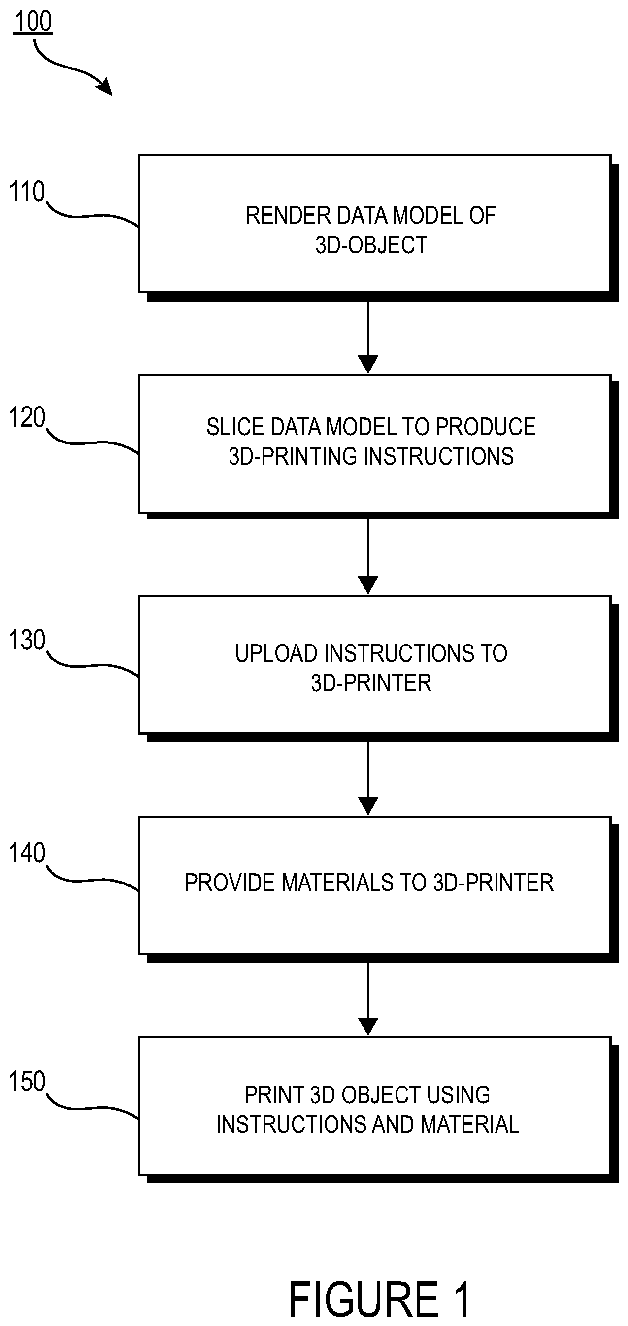
FIG. 1 is a flow diagram illustrating an exemplary process of initiating a process of 3-D printing.
FIG. 2 is a block diagram of an exemplary 3-D printer.
FIGS. 3A-D are diagrams illustrating side views of an exemplary panel and exemplary 3D-printed tooling shells, and various stages of a process for using a 3D-printed tooling shell for producing the panel.
FIGS. 4A-B are a flow diagram illustrating an exemplary process for producing a 3D-printed tooling shell used for producing a panel for use in a structure.
FIG. 5 is a cross-sectional view of an exemplary 3-D printed tooling shell incorporating hollow structures and integrated channels.
FIG. 6 is a flow diagram illustrating an exemplary process for producing a panel using a 3D-printed tooling shell incorporating hollow structures and integrated channels and for producing a panel therefrom.
DETAILED DESCRIPTION
The detailed description set forth below in connection with the appended drawings is intended to provide a description of various exemplary embodiments of tooling shells and method of producing tolling shells and is not intended to represent the only embodiments in which the invention may be practiced. The term "exemplary" used throughout this disclosure means "serving as an example, instance, or illustration," and should not necessarily be construed as preferred or advantageous over other embodiments presented in this disclosure. The detailed description includes specific details for the purpose of providing a thorough and complete disclosure that fully conveys the scope of the invention to those skilled in the art. However, the invention may be practiced without these specific details. In some instances, well-known structures and components may be shown in block diagram form, or omitted entirely, in order to avoid obscuring the various concepts presented throughout this disclosure.
A particular focus of attention in recent years has been the use of composite materials for creating panels. Generally, a composite material is formed from two or more different materials that are combined together to create specific properties that are superior to the original properties of the individual materials. Composite materials such as fiberglass and carbon fiber are used in the manufacture of composite panels used in transport or other mechanical structures.
Carbon fiber is a common material used in the formation of numerous, high-performance structures requiring stiffness, strength and durability without the heavy weight often associated with alternative candidate materials. Carbon Fiber Reinforced Polymer (CFRP) is an extremely strong and lightweight fiber-reinforced plastic. As the name suggests, CFRP includes materials formed using a combination of carbon fibers and a polymer-based resin (or other binding agent) to form a new composite material with durable properties that exceed its constituent materials. Due to its strength and lightweight nature, CFRP is frequently used in the manufacture of body panels and other components for vehicles, boats, motorcycles, aircraft, and other mechanized assemblies, in addition to having numerous other industrial and commercial applications.
In conventional production techniques, a tool for molding the composite material is typically manufactured using labor-intensive processes. For example, a machining process may be used to manufacture a pair of tooling shells which may each constitute one of a positive and a negative section of a mold. Materials and resin may be placed in the mold between the positive and negative tooling shell sections to thereby shape a panel constituting the target composite material. The tooling shells, in turn, are typically composed of one or more materials that are chemically and structurally suitable for use in molding the subject materials.
Suitable candidate materials for the tooling shells include those that can withstand the pressures associated with molding and that have thermal characteristics compatible with a given composite material. Unfortunately, many such candidate materials are difficult and costly to machine into tooling shells using traditional methods. These latter methods often involve the time-consuming and laborious process of shaping an expensive block of material having tough or ductile properties or other undesirable characteristics not conducive to the machining process. As an illustration, some otherwise desirable materials may be soft and gummy, making them difficult to accurately cut. This renders tasks like carving the material and formulating detailed structure therein a particular manufacturing challenge. For these and other reasons, labor-intensive machining techniques can result in complex and costly obstacles to manufacturers. They can also impose significant practical limitations on the allowable shape, size and geometrical complexity of the resulting tooling shell such that, for example, it may be difficult or impractical to construct certain desired features or to streamline an optimal shape of the shell. The resulting tooling shell may be bulky and unwieldy, imposing additional burdens on persons working with the materials to mold panels. Certain aspects of the disclosure herein consequently address the challenges of producing panels using tooling shells. One such aspect includes the use of 3-D printed tooling shells to mold the panels, as described further below.
The use of 3-D printing in the context of composite tooling provides significant flexibility for enabling manufacturers of structures incorporating body panels to manufacture parts with complex geometries. For example, 3-D printing techniques provide manufacturers with the flexibility to design and build parts having intricate internal lattice structures and/or profiles that are not possible to manufacture via traditional manufacturing processes.
FIG. 1 is a flow diagram 100 illustrating an exemplary process of initiating a process of 3-D printing. A data model of the desired 3-D object to be printed is rendered (step 110). A data model is a virtual design of the 3-D object. Thus, the data model may reflect the geometrical and structural features of the 3-D object, as well as its material composition. The data model may be created using a variety of methods, including 3D scanning, 3D modeling software, photogrammetry software, and camera imaging.
3D scanning methods for creating the data model may also use a variety of techniques for generating a 3-D model. These techniques may include, for example, time-of flight, volumetric scanning, structured light, modulated light, laser scanning, triangulation, and the like.
3-D modeling software, in turn, may include one of numerous commercially available 3-D modeling software applications. Data models may be rendered using a suitable computer-aided design (CAD) package, for example in an STL format. STL files are one example of a file format associated with commercially available CAD software. A CAD program may be used to create the data model of the 3-D object as an STL file. Thereupon, the STL file may undergo a process whereby errors in the file are identified and resolved.
Following error resolution, the data model can be "sliced" by a software application known as a slicer to thereby produce a set of instructions for 3-D printing the object, with the instructions being compatible and associated with the particular 3-D printing technology to be utilized (step 120). Numerous slicer programs are commercially available. Generally, the slicer program converts the data model into a series of individual layers representing thin slices (e.g., 100 microns thick) of the object be printed, along with a file containing the printer-specific instructions for 3-D printing these successive individual layers to produce an actual 3-D printed representation of the data model.
A common type of file used for this purpose is a G-code file, which is a numerical control programming language that includes instructions for 3-D printing the object. The G-code file, or other file constituting the instructions, is uploaded to the 3-D printer (step 130). Because the file containing these instructions is typically configured to be operable with a specific 3-D printing process, it will be appreciated that many formats of the instruction file are possible depending on the 3-D printing technology used.
In addition to the printing instructions that dictate what and how an object is to be rendered, the appropriate physical materials necessary for use by the 3-D printer in rendering the object are loaded into the 3-D printer using any of several conventional and often printer-specific methods (step 140). In fused deposition modelling (FDM) 3-D printers, for example, materials are often loaded as filaments on spools, which are placed on one or more spool holders. The filaments are typically fed into an extruder apparatus which, in operation, heats the filament into a melted form before ejecting the material onto a build plate or other substrate, as further explained below. In selective laser sintering (SLS) printing and other methods, the materials may be loaded as powders into chambers that feed the powder to a build platform. Depending on the 3-D printer, other techniques for loading printing materials may be used.
The respective data slices of the 3-D object are then printed based on the provided instructions using the material(s) (step 150). In 3-D printers that use laser sintering, a laser scans a powder bed and melts the powder together where structure is desired, and avoids scanning areas where the sliced data indicates that nothing is to be printed. This process may be repeated thousands of times until the desired structure is formed, after which the printed part is removed from a fabricator. In fused deposition modelling, parts are printed by applying successive layers of model and support materials to a substrate. In general, any suitable 3-D printing technology may be employed for purposes of this disclosure.
FIG. 2 is a block diagram of an exemplary 3-D printer 200. While any number of 3-D printed technologies can be suitably employed, the 3-D printer 200 of FIG. 2 is discussed in the context of an FDM technique. 3-D printer 200 includes an FDM head 210 which in turn includes extrusion nozzles 250A and 250B, a moveable build stage 220, and a build plate 230 at the top of the build stage 220.
Depending on the intended composition of the structure and the need for any support material for providing support to overhanging elements of the structure that might otherwise be subject to possible gravitational deformation or collapse, a plurality of materials may be used for printing an object. One or more suitable filament materials 260 may be wound on a spool (not shown) and fed into FDM head 210. (In other technologies described above, the material may be provided as a powder or in other forms). The FDM head 210 can be moved in X-Y directions based on the received printing instructions by a numerically controlled mechanism such as a stepper motor or servo motor. The material, which may in one exemplary embodiment constitute a thermoplastic polymer, may be fed to the FDM head 210 which includes the extrusion nozzles 250A and 250B. The extruder in FDM head 210 heats the filament material 260 into a molten form, and extrusion nozzle 250a ejects the molten material and deposits it onto the build plate 230 of build stage 220.
Responsive to the received printing instructions, the FDM head 210 moves about a horizontal (X-Y) plane such that extrusion nozzle 250A drops the material 260 at the target location to form a line 240 of applied material. (The FDM head 210 may also be configured to move in the Z-direction and/or to rotate about one or more axes in certain configurations). The layer 270 of material 260, including line 240, is formed by depositing the material 260 line by line, with each line of the material 260 hardening as the material is deposited on the build plate 230. After one layer 270 is formed at the appropriate locations in the X-Y plane, the next layer may be formed in a similar way.
The build plate 230 may be a component of a controlled table moveable in at least the vertical Z direction. When rendering of a layer 270 is completed, the build stage 220 and build plate 230 may lower by an amount proportional to the thickness of layer 270 in the vertical (Z) direction so that the printer can begin application of the next layer, and so on until a plurality of cross sectional layers 240 having a desired shape and composition are created.
While a substantially rectangular structure of layers is shown for purposes of simplicity in this illustration, it will be appreciated that the actual printed structure may embody substantially any shape and configuration depending on the data model. That is, the actual shape of the rendered layers will correspond to the defined geometry of the 3D-model being printed.
In addition, as indicated above, a plurality of different materials may be used to print the object. In some instances, two different materials 260 and 280 may concurrently be applied by respective extruder nozzles 250A and 250B.
Panels for transport and other mechanical structures may be constructed from various composite materials that provide strong support with a lightweight structure. One such material attractive for use in molding these panels is Invar, a nickel steel (Ni--Fe) alloy. Invar is used as a tooling shell in the production of composites such as CFRP and the like. Invar is known for its low coefficient of thermal expansion (CTE) and thus its relative lack of expansion or contraction with temperature changes. Invar has a CTE that is relatively similar to that of Carbon Fiber Reinforced Polymer (CFRP). For this reason, Invar is commonly used as a mold in CFRP composite tooling. The use of an Invar tool may be particularly desirable for producing CFRP structures because a significant CTE mismatch between the tooling material and the composite material can cause unwanted thermal expansion of materials. Such expansion can be detrimental in manufacturing high tolerance composite parts. The use of Invar in connection with CFRP tooling reduces the phenomenon of CTE mismatch. Invar is stable and nearly immune to shrinkage or expansion due to extreme changes in temperature. Invar is consequently desirable for use in molding CFRP and similar materials.
An exemplary table setting forth Invar's approximate CTE as a function of its temperature is provided below.
TABLE-US-00001 Temperature (.degree. F.) CTE (.times.10.sup.-6 .degree. F..sup.-1) 200 0.72 300 1.17 500 2.32 700 4.22
In addition, the approximate modulus of elasticity of Invar is 20.5 Mpsi. The elasticity modulus is a general measure of a material's resistance to being deformed when a force (such as a molding force) is applied to it. This value of the modulus of elasticity provides Invar with a high stiffness that is suitable for dimensional stability of the resulting tooling shell.
In other embodiments, a method for 3-D printing tooling shell includes using, in lieu of Invar, a different alloy that has thermal properties and stiffness characteristics that are suitable for molding a composite panel including carbon fiber. Thus, for example, an alloy that includes characteristics that are comparable to the exemplary values described above may be a suitable material for the 3-D printed tooling shell.
As discussed above, many materials that are otherwise suitable for use as tools in producing body panels are difficult to construct. Being tough and ductile, Invar, for one, is notoriously difficult and expensive to machine. The difficulty and time-consuming nature of sculpting Invar using traditional machining techniques often results in Invar tools that are unnecessarily thick and heavy, making such tools more difficult for workers to handle in the molding process. Further, the machining limitations of Invar and similar materials make it difficult or impractical to accurately integrate detailed structural features in the tooling shell that may otherwise be useful in the ensuing molding process. Thus, existing Invar and similar tools lack versatility. The cost and complexity of the machining and tooling processes for these materials increase significantly in direct proportion to the increase of part performance requirements (such as, for example, in vehicle and aircraft applications), the number of parts to be produced, the complexity of the parts, and other factors. Additionally, the excessive mass of these tools requires extended thermal ramp-up and cool down parameters in the molding process, limiting the production cycle time and associated rate capability.
To address these and other deficiencies in the art, a 3-D printed tooling shell may be incorporated, for example, as a section of a mold for use in producing panels for use in structures. In an exemplary embodiment, the 3-D printed tooling shell includes Invar or similarly performing alloys and is used to mold composite body panels using a carbon fiber composite material such as CFRP. Preferably the 3-D printed tooling shell is comprised of substantially Invar or a similar alloy. "Substantially Invar" means that the 3-D printed tooling shell is comprised of pure Invar, or principally of Invar with some minor composition of other materials (whether intended materials or impurities) that do not materially affect the CTE or other desirable properties of the tooling shell to serve its intended purpose, or of an Invar-like alloy that has similar mechanical and thermal (CTE) characteristics.
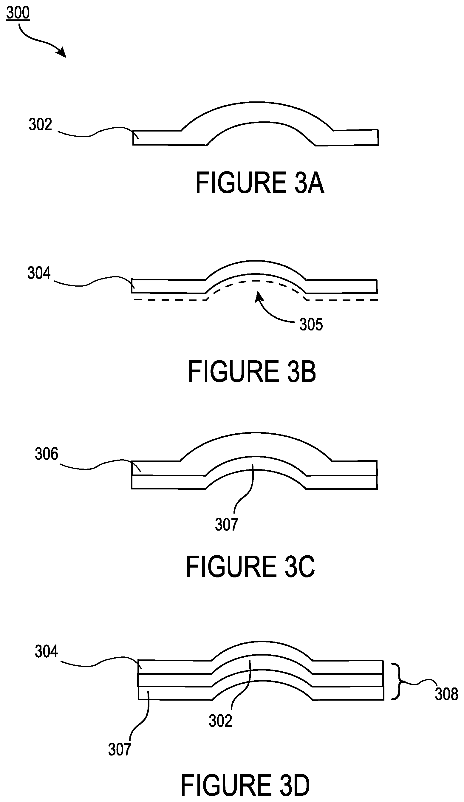
FIGS. 3A-D are diagrams illustrating side views of a panel and 3D-printed tooling shells, and various stages of a process for using a 3D-printed tooling shell for producing the panel. FIG. 4 is a flow diagram illustrating an exemplary process for producing a 3D-printed tooling shell used for producing a panel for use in a structure. In one exemplary embodiment, the tooling shell is being used as one of a positive or negative a mold to produce the body panel in one of any conventional molding processes. In the embodiment shown, the body panel contemplated for production is composed of CFRP.
It should be understood that the tooling shells herein are not limited to molding composite body panels, and practitioners in the art will appreciate that the disclosed tooling shells can be used in a variety of industrial and commercial applications.
In the paragraphs that follow, FIGS. 3 and 4 will be collectively referenced, where appropriate.
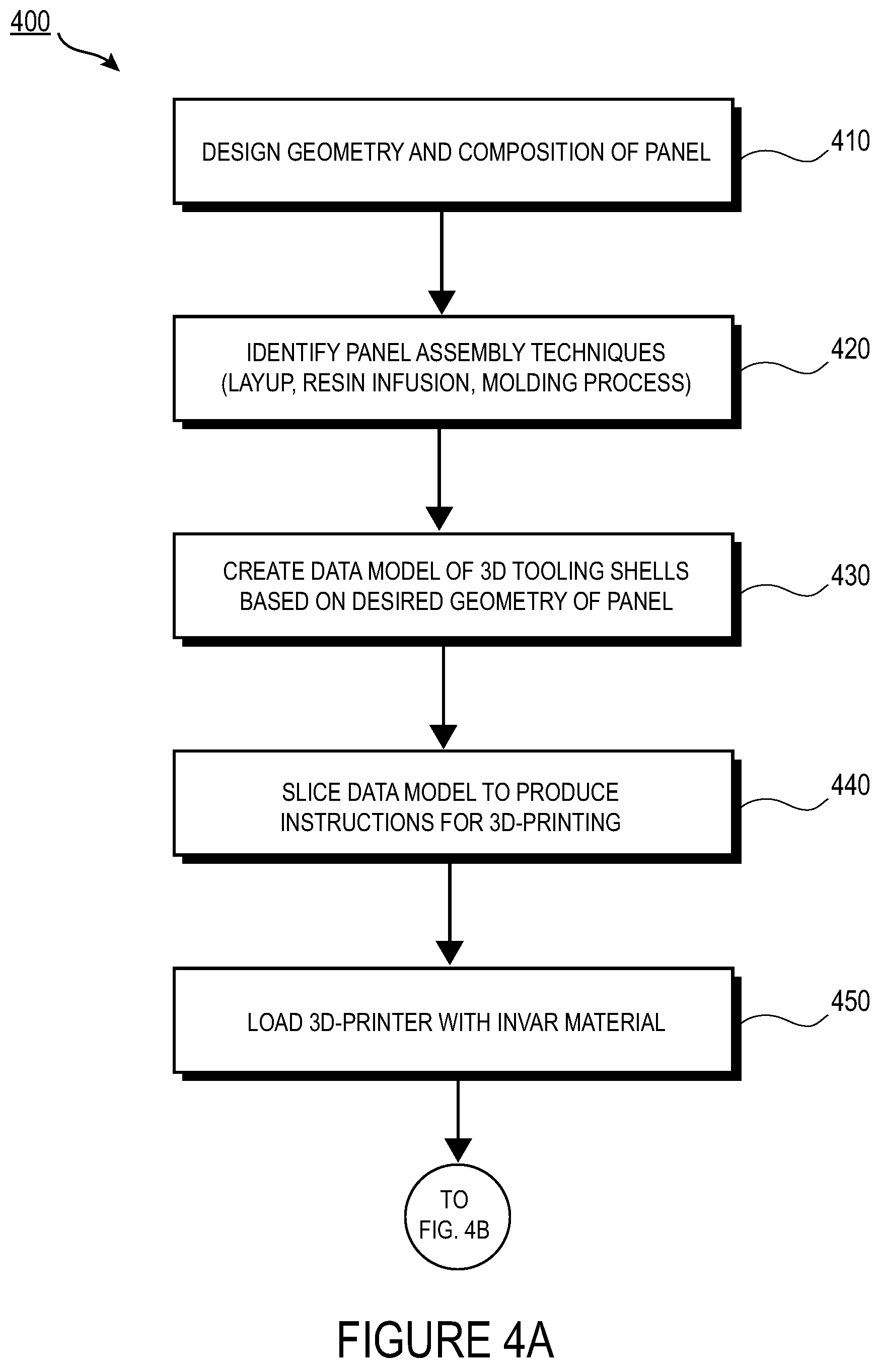
Referring initially to FIG. 3A and FIG. 4, the topology optimization phase at the concept level of the design process is described. In this phase, the geometry and composition of a composite body panel 302 may be designed (step 410). That is, the panel's overall topology, its specific composition of materials, its geometrical and structural features, and any other desired properties or characteristics may be defined at this stage. The material layout for the body panel may be optimized based on an understood set of loads and design constraints such that the layout adheres to some target performance objectives. In the case of manufacturing an automobile, for example, this step may include identifying the structure, shape and features of the panel desired, and the composition of materials necessary for producing the panel, that allow the panel to fall within certain desired specifications (e.g., weight requirements and safety specifications, etc.).
The specific panel assembly techniques may then be identified (step 420). This step may include, for example, identification and selection of the specific method of assembly of the panel 302 (such as an identification of the molding and resin infusion processes to be used), selection of the layup process (such as wet versus dry layup, etc.), determination of the resin infusion process, and determination of the architecture and composition of the tooling shells. That is, this step may further include determination of the desired structures, geometries and compositions of the tooling shells based on the above-identified properties of the panel design. For example, tooling shells may have different structures based on whether the tooling shell is part of a positive or negative mold section, as described further below.
It will be appreciated that in other embodiments and depending on the application involved, part or all of the steps 410 and 420 in FIG. 4 may equally well occur in reverse order such that the manufacturing and assembly techniques may precede one or more of the steps involved in designing the features of the panel.
In addition, it is generally understood that in many conventional molding techniques, at least two tooling shells are used as part of a mold for creating a part. For example, in an exemplary embodiment, a molding process as described herein may use a first tooling shell as a positive section of the mold and a second tooling shell as a negative section of the mold. The positive section of the mold may ultimately embody the intended shape of the part, such as the external surface of a body panel on a vehicle. The construction and number of tooling shells used herein may consequently vary depending on the specific molding techniques employed. It should be noted that wide variety of molding techniques may be employed depending on the application and potentially other factors such as the anticipated volume of production, etc.
For example, in one exemplary embodiment, the use of prepregs with vacuum bagging equipment is employed. Vacuum bagging is a technique used to create mechanical pressure on the laminate during the cure cycle. Among other benefits, pressurizing the composite laminate using vacuum bagging removes trapped air, compacts the fiber layers, and reduces humidity. In another exemplary embodiment, autoclave molding using high pressures is employed. Autoclave molding is a standard composite manufacturing procedure that provides pressure and temperature according to a particular thermal curing cycle. The high pressure applied using this technique ensures a significant void reduction inside the composite structure. The aforementioned techniques may be suitable in certain implementations involving low production volumes of parts.
With reference to the panel assembly techniques (step 420), which may include identification of the features of the tooling shell, a suitable data model may be constructed based on these features (step 430). The data model may describe the 3-D geometry and composition of the tooling shells as identified with respect to step 410. In an exemplary embodiment, a CAD program is used to create one or more files, such as an STL file, containing the data model. In some embodiments, the data model generation process may overlap with one or more of the processes identified with respect to steps 410 and 420. For example, the data model may be generated concurrently with the panel design.
The data model generated in step 430 may be converted via a slicer program or other available procedure to a set of instructions suitable for input to a 3D printer (step 440). Generally, the structure and geometry of the tooling shells to be rendered may be developed and described in one or more electronic files and/or software programs to be used as the input of a 3-D printer, as is conventionally understood.
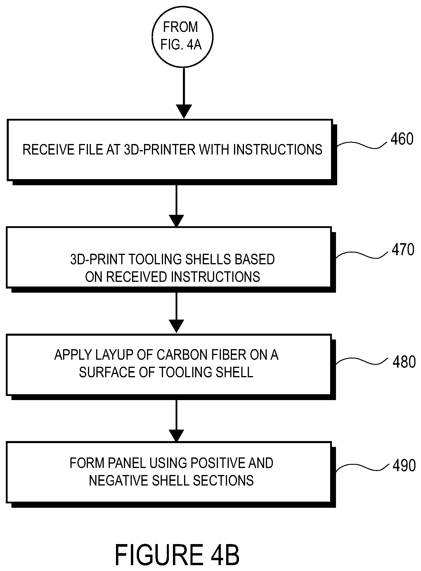
The 3-D printer is then loaded with the suitable printing materials, by way of example, Invar or, if desired, additional materials for use as the model material in constructing the tooling shell along with any support materials required (step 450). As discussed above, the materials may be loaded as a spool with filament in a 3D printer, as a powder, or through another suitable technique specific to the 3-D printer in use. In addition, the program files generated in connection with step 440, above, are input to the 3-D printer such that the 3-D printer receives instructions for printing the tooling shell (step 460). It will be appreciated that the supplying of materials to the 3-D printer may occur at any suitable stage of the processes described herein and is not necessarily limited to the order ascribed this step in FIG. 4.
Using the instructions, the 3-D printer prints a tooling shell 304 (FIG. 3B, FIG. 4, step 470). In general, 3-D printing may include a process of making a three-dimensional structure based on a computational or electronic model as an input. For example, the 3-D printer may print the tooling shell having a complex inner lattice matrix section in the tooling shell. The 3-D printer can be configured to generate the tooling shell through additive and/or subtractive manufacturing, or via another method. Any suitable 3-D printing process may be used. The 3-D printer may be a direct metal laser sintering (DMLS) printer, electron beam melting (EBM) printer, fused deposition modeling (FDM) printer, a Polyjet printer, or any of the techniques described elsewhere in this disclosure. The 3-D printer may use extrusion deposition, granular binding, lamination, or stereolithography. As described above, the 3-D printing process may involve breaking down the design of the 3-D object into a series of successive digital layers or slices, which the printer will then form layer-by-layer until the rendered object is completed. Tooling shells as described herein may have different geometries and complexities and may be printed in a layer-by-layer fashion. A wide range of geometric designs and detailed internal and external features of the tooling shell may also be accommodated.
In addition, the 3-D printing as contemplated herein may involve complex matrix arrays as backing structures, eliminating the need for temporary support material during the 3DP process, and giving reduced tooling thermal mass and lower material usage, thereby reducing manufacturing cost of the tool and lower molding process time due to reduced thermal cycle time.
The example in FIG. 3B shows a simplified geometry of a resulting tooling shell 304 that is intentionally designed to be relatively thin. In an exemplary embodiment, the tooling shell may be an Invar tooling shell, which is a tooling shell substantially composed of Invar as defined above. Shell thickness and backing structure matrix density can be optimized to minimize tool mass based on tool size and form so that sufficient tool stiffness and stability during curing is met. Geometry and dimensions for channels can be optimized similarly.
Thus, in contrast to prior techniques involving the machining of often unwieldy and unnecessarily large chunks of Invar material, 3-D printing the tooling shell (using Invar or other suitable materials) provides significant flexibility to design and print a tool having a shape and geometry that is generally easier to manipulate in the manufacturing process. Thus, one of several advantages of the 3-D printed tooling shell 304 is that, in contrast to a bulky or heavy shells that are machined using conventional methods, the tooling shell 304 may be constructed to be relatively thin and lightweight, saving material costs.
It will nonetheless be appreciated that any number of desired tool shapes and structures may be contemplated depending on the molding process to be used and design requirements of the panel to be produced using the tooling shell. The use of 3-D printing of the tooling shell also provides the designer with significant flexibility to produce shells having very complex shapes to mold more complicated panel designs.
Referring still to FIG. 3B, a geometry 305 of a panel to be molded within the tooling shell 304 may be designed to conform to the shape of an inner surface of the tooling shell 304, depending on how the mold is configured. In this manner, the tooling shell acts as a section of a mold to shape the composite material that will be cured into the panel, as described further below.
After the tooling shells are printed, they may be used to produce a panel (FIG. 4, steps 480, 490). The composite layup may be performed using the tooling shell. FIG. 3C illustrates a second 3-D printed tooling shell 307 designed to be used in conjunction with the first 3-D printed tooling shell 304 as first and second sections of a mold. In this example, carbon fiber material 306 (or another suitable material) may be applied via a layup process on the back or outer surface of the tooling shell 307 as a first step in producing a panel. The carbon fiber material 306 may be laid over the tooling shell 307. (In other embodiments, the material 306 may alternately or additionally be applied over an inner surface of tooling shell 304).
In one exemplary embodiment, a layup uses pre-impregnated ("prepreg") carbon fiber plies that are delivered onto the tooling shell 307 with the resin matrix applied. The prepreg technique provides effective resin penetration and assists in ensuring substantially uniform dispersion of the resin. The prepreg plies may be applied onto the tooling shell 307 to form a laminate stack.
In another embodiment, a dry layup may use dry woven fiber sheets. Resin may thereupon be applied to the dry plies after layup is complete, such as by resin infusion. In an alternative exemplary embodiment, wet layup may be used wherein each ply may be coated with resin and compacted after being placed.
FIG. 3D shows a mold 308. Where Invar is used, the Invar tooling shell 304 is applied over the Invar tooling shell 307 as positive and negative sections in a mold to shape the carbon fiber material into the form of the body panel 302 (step 490). Upon completion of the molding process, the carbon fiber material may, for example, be vacuum compacted and baked in an oven for a designated time period.
The specific molding and resin infusion processes used during these stages may vary depending on variables such as molding techniques, design constraints, and desired manufacturing yield. Generally, the 3-D-printed tooling shell may be used in connection with a variety of composite manufacturing techniques including, for example, Resin Transfer Molding (RTM), hand layup, prepregs, sheet molding, and Vacuum Assisted Resin Transfer Molding (VARTM).
For example, with reference to the mold 308 of FIG. 3D following carbon fiber layup, clamps may be affixed on respective left and right sides of the mold 308 to press tooling shells 304 and 307 together. One of the tooling shells may include a channel (as described below) through which low viscosity resin and an appropriate catalyst can flow via a resin injector. Temperature control may also be maintained via one or more heating channels.
The use of the above-described techniques to produce the tooling shells 304 and 307 may be suitable in some implementations for manufacturing approximately 1-500 composite body panels. In other instances, these techniques may be employed to produce more than 500 parts, whether alone or using a platen press or other method. Among other benefits, the tooling technique according to these aspects accords manufacturers with significant flexibility to produce both tooling shells and composite panels having varying geometries and complexities.
As an illustration of this flexibility, tooling shells may be 3-D printed incorporating one or more hollow sections. The use of defined hollow sections in the tooling shells achieved via 3-D-printing may result in considerable weight savings for the tooling. In addition to decreased costs as a result of saving material and reduced time for 3-D-printing, the tooling shells constructed as described herein may be made easier and less wieldy for use in the panel tooling process.
In another exemplary embodiment, the tooling shells are 3-D-printed with integrated channel structures. Various channels may be used in connection with the manufacturing processes of composite panels and other structures. These channels may, for example, include heating or cooling channels, channels for resin infusion, channels for vacuum generation, and the like. The channels can easily be integrated into the tooling shells themselves via 3-D printing techniques. In addition to providing great flexibility, these techniques may save the manufacturer considerable time and expense with respect to the machining processes of Invar and other materials used in such tooling shells.
FIG. 5 is an exemplary cross-sectional view of a 3-D printed tooling shell 500 incorporating hollow structures and integrated channels. The tooling shell may be composed of Invar, in whole or part, or of one or more different materials, depending on the application for which the tooling shell is suited and on the composition of the panel to be produced. Unlike conventional Invar tooling shells and other materials that are comparatively difficult to machine, the 3-D printed tooling shell 500 of FIG. 5 can be modeled to include any number of complex geometries.
For example, the tooling shell 500 may comprise a plurality of hollow sections 508. These hollow sections 508 are, more fundamentally, defined volumes of material vacancies within the tooling shell 500. These defined volumes function to reduce an overall weight of the tooling shell 500 without sacrificing the amount of structural integrity required for the tooling shell 500 to be used in the molding process. While four hollow sections 508 are shown in this example, any number of hollow sections, including a single hollow section disposed substantially along an axis of the tooling shell 500, may be used. Also, in lieu of hollow sections 508 disposed exclusively within the material, the hollow sections may also be formed as one or more indentations in the material, such that at least one surface of the hollow section is exposed and such that the hollow section is not necessarily entirely within the tooling shell 500. Alternatively, the sections 508 may not be entirely empty but may, for maintenance of structural integrity or for other purposes, be filled with a substance that is substantially lighter than the base material(s) used to create the tooling shell.
The use of hollow sections 508 is particularly advantageous in numerous contexts. One context involves workers performing various stages of a manual molding process. Carrying the tooling shells and assembling the mold becomes easier, especially where, as is commonplace, the base materials from which the tooling shells are formed are otherwise heavy and impose burdens on the workers assembling and using the mold.
In another exemplary embodiment, the 3-D printed tooling shell 500 comprises a plurality of integrated channels 502, 504, 506. These channels constitute spaces within the tooling shell 500 that channel substances, gasses or heat to or from a surface 514 of the tooling shell 500. In the example shown, channel 502 is used for resin infusion, channel 504 is used to create a vacuum between the tooling shells to facilitate resin infusion from channel 502, and channel network 506 is used to maintain a temperature of a material by transferring heat to or from surface 514. Channel network 506 may also be used to provide high heat conditions to an area near surface 514 for heating the materials or curing resin. Openings 510 are provided for each of the channels 502, 504 and 506 to transfer the substances or heat to or from surface 514. Similarly, openings 512, shown at the lower surface 516 of the tooling shell 500, may be coupled to devices such as a resin injector, vacuum chamber, or temperature control unit. It will be appreciated that the number, geometry and functions of the channels 502, 504 and 506 can vary depending on the desired implementation. In addition, while openings 510 and 512 are shown at the upper surface 514 and lower surface 516, respectively, of the 3-D printed tooling shell 500, the openings may extend to different parts of the tooling shell 500. For example, one or more of the openings 512 may be disposed on a side of the tooling shell.
Ordinarily, such complex geometries of tooling shell 500 would not be practical for many materials suitable for molding. Further, many manufacturers of composites lack the equipment necessary to cut and polish metal tools such as Invar, so the services of a tooling specialist may be required, adding to the manufacturers' cost. Further, Invar is one of the most expensive metallic tooling materials and, especially for large parts, the sheer size and weight of the tools makes them difficult to handle. Additional parts including, for example, jigs and fixtures may be needed to add features to blocks of material during a conventional machining process, making the conventional techniques more complex and time consuming. Accordingly, the use of 3-D printing to render a tooling shell having a streamlined, preconfigured geometry with hollow sections for lightweight handling and molding features including integrated channel structures may impart substantial cost savings and provide significant benefits.
FIG. 6 is a flow diagram 600 illustrating an exemplary process for producing a 3D-printed tooling shell incorporating hollow structures and integrated channels. At 602, a 3-D printer receives instructions for printing based on a data model as described in more detail above. In addition, at 604, the 3-D printer receives one or more materials for use in printing the tooling shell, such as the material(s) constituting the tooling shell. In some cases, the required materials may include support materials for use in temporarily providing support to the structure by supporting structure overhangs and providing a temporary fill for the volumes of the hollow sections and/or channels to be formed.
At 606, the tooling shell is 3-D printed using any suitable printing technique. As part of the printing process 606, a sub-step 608 may involve forming a plurality of channels disposed within the structure that will be used for resin infusion, vacuum generation, or heat transfer. Similarly, a sub-step 610 may involve the formation of one or more hollow sections to reduce an overall weight of the tooling shell, while not removing so much material as to compromise the tooling shell's overall structural integrity to perform the task it is designed to perform. At 612, a panel is molded with the tooling shell using any suitable technique, such as those described in this disclosure.
The previous description is provided to enable any person skilled in the art to practice the various aspects described herein. Various modifications to these exemplary embodiments presented throughout this disclosure will be readily apparent to those skilled in the art, and the concepts disclosed herein may be applied to other tooling shells and methods of producing tooling shells. Thus, the claims are not intended to be limited to the exemplary embodiments presented throughout the disclosure, but are to be accorded the full scope consistent with the language claims. All structural and functional equivalents to the elements of the exemplary embodiments described throughout this disclosure that are known or later come to be known to those of ordinary skill in the art are intended to be encompassed by the claims. Moreover, nothing disclosed herein is intended to be dedicated to the public regardless of whether such disclosure is explicitly recited in the claims. No claim element is to be construed under the provisions of 35 U.S.C. .sctn. 112(f), or analogous law in applicable jurisdictions, unless the element is expressly recited using the phrase "means for" or, in the case of a method claim, the element is recited using the phrase "step for."
* * * * *
D00001
D00002
D00003
D00004
D00005
D00006
D00007
XML
uspto.report is an independent third-party trademark research tool that is not affiliated, endorsed, or sponsored by the United States Patent and Trademark Office (USPTO) or any other governmental organization. The information provided by uspto.report is based on publicly available data at the time of writing and is intended for informational purposes only.
While we strive to provide accurate and up-to-date information, we do not guarantee the accuracy, completeness, reliability, or suitability of the information displayed on this site. The use of this site is at your own risk. Any reliance you place on such information is therefore strictly at your own risk.
All official trademark data, including owner information, should be verified by visiting the official USPTO website at www.uspto.gov. This site is not intended to replace professional legal advice and should not be used as a substitute for consulting with a legal professional who is knowledgeable about trademark law.