Stent for prosthetic heart valves
Eberhardt , et al. Sep
U.S. patent number 10,758,343 [Application Number 15/099,075] was granted by the patent office on 2020-09-01 for stent for prosthetic heart valves. This patent grant is currently assigned to Medtronic, Inc.. The grantee listed for this patent is Medtronic, Inc.. Invention is credited to Maria Awad, Carol E. Eberhardt, Carolyn Majkrzak, Timothy R. Ryan, Janice L. Shay, Charles Tabor, Melissa R. Young.


| United States Patent | 10,758,343 |
| Eberhardt , et al. | September 1, 2020 |
Stent for prosthetic heart valves
Abstract
A stented valve including a stent structure including a generally tubular body portion having a first end, a second end, an interior area, a longitudinal axis, and a plurality of vertical wires extending generally parallel to the longitudinal axis around a periphery of the body portion, wherein the plurality of vertical wires includes multiple commissure wires and at least one structural wire positioned between adjacent commissure wires, and a plurality of V-shaped wire structures having a first end, a second end, and a peak between the first and second ends, wherein a first end of each V-shaped structure extends from a first vertical wire and a second end of each V-shaped structure extends from a second vertical wire that is adjacent to the first vertical wire, wherein each V-shaped structure is oriented so that its peak is facing in the same direction relative to the first and second ends of the body portion, and a valve structure including a plurality of leaflets attached to the stent structure within the tubular body portion.
| Inventors: | Eberhardt; Carol E. (Fullerton, CA), Tabor; Charles (St. Cloud, MN), Majkrzak; Carolyn (Chanhassen, MN), Ryan; Timothy R. (Minnetrista, MN), Young; Melissa R. (Cleveland Heights, OH), Awad; Maria (Irvine, CA), Shay; Janice L. (Lake Forest, CA) | ||||||||||
|---|---|---|---|---|---|---|---|---|---|---|---|
| Applicant: |
|
||||||||||
| Assignee: | Medtronic, Inc. (Minneapolis,
MN) |
||||||||||
| Family ID: | 40900015 | ||||||||||
| Appl. No.: | 15/099,075 | ||||||||||
| Filed: | April 14, 2016 |
Prior Publication Data
| Document Identifier | Publication Date | |
|---|---|---|
| US 20160296327 A1 | Oct 13, 2016 | |
Related U.S. Patent Documents
| Application Number | Filing Date | Patent Number | Issue Date | ||
|---|---|---|---|---|---|
| 14087990 | Nov 22, 2013 | 9333100 | |||
| 12358980 | Jan 14, 2014 | 8628566 | |||
| 61062207 | Jan 24, 2008 | ||||
| Current U.S. Class: | 1/1 |
| Current CPC Class: | A61F 2/2436 (20130101); A61F 2/2403 (20130101); A61F 2/243 (20130101); A61F 2/82 (20130101); A61F 2/2412 (20130101); A61F 2/2418 (20130101); A61F 2002/9505 (20130101); A61F 2002/9511 (20130101); A61F 2250/0098 (20130101) |
| Current International Class: | A61F 2/24 (20060101); A61F 2/82 (20130101); A61F 2/95 (20130101) |
References Cited [Referenced By]
U.S. Patent Documents
| 3334629 | August 1967 | Cohn |
| 3409013 | November 1968 | Berry |
| 3540431 | November 1970 | Mobin-Uddin |
| 3587115 | June 1971 | Shiley |
| 3628535 | December 1971 | Ostrowsky et al. |
| 3642004 | February 1972 | Osthagen et al. |
| 3657744 | April 1972 | Ersek |
| 3671979 | June 1972 | Moulopoulos |
| 3714671 | February 1973 | Edwards et al. |
| 3755823 | September 1973 | Hancock |
| 3795246 | March 1974 | Sturgeon |
| 3839741 | October 1974 | Haller |
| 3868956 | March 1975 | Alfidi et al. |
| 3874388 | April 1975 | King et al. |
| 4035849 | July 1977 | Angell et al. |
| 4056854 | November 1977 | Boretos et al. |
| 4106129 | August 1978 | Carpentier et al. |
| 4222126 | September 1980 | Boretos et al. |
| 4233690 | November 1980 | Akins |
| 4265694 | May 1981 | Boretos |
| 4291420 | September 1981 | Reul |
| 4297749 | November 1981 | Davis et al. |
| 4339831 | July 1982 | Johnson |
| 4343048 | August 1982 | Ross et al. |
| 4345340 | August 1982 | Rosen |
| 4425908 | January 1984 | Simon |
| 4470157 | September 1984 | Love |
| 4501030 | February 1985 | Lane |
| 4506394 | March 1985 | Debard |
| 4574803 | March 1986 | Storz |
| 4580568 | April 1986 | Gianturco |
| 4592340 | June 1986 | Boyles |
| 4610688 | September 1986 | Silvestrini et al. |
| 4647283 | March 1987 | Carpentier et al. |
| 4648881 | March 1987 | Carpentier et al. |
| 4655771 | April 1987 | Wallsten |
| 4662885 | May 1987 | DiPisa, Jr. |
| 4665906 | May 1987 | Jervis |
| 4681908 | July 1987 | Broderick et al. |
| 4710192 | December 1987 | Liotta et al. |
| 4733665 | March 1988 | Palmaz |
| 4777951 | October 1988 | Cribier et al. |
| 4787899 | November 1988 | Lazarus |
| 4796629 | January 1989 | Grayzel |
| 4797901 | January 1989 | Goerne et al. |
| 4819751 | April 1989 | Shimada et al. |
| 4834755 | May 1989 | Silvestrini et al. |
| 4856516 | August 1989 | Hillstead |
| 4872874 | October 1989 | Taheri |
| 4878495 | November 1989 | Grayzel |
| 4878906 | November 1989 | Lindemann et al. |
| 4883458 | November 1989 | Shiber |
| 4909252 | March 1990 | Goldberger |
| 4913141 | April 1990 | Hillstead |
| 4917102 | April 1990 | Miller et al. |
| 4922905 | May 1990 | Strecker |
| 4954126 | September 1990 | Wallsten |
| 4966604 | October 1990 | Reiss |
| 4979939 | December 1990 | Shiber |
| 4986830 | January 1991 | Owens et al. |
| 4994077 | February 1991 | Dobben |
| 5002559 | March 1991 | Tower |
| 5007896 | April 1991 | Shiber |
| 5026366 | June 1991 | Leckrone |
| 5032128 | July 1991 | Alonso |
| 5037434 | August 1991 | Lane |
| 5047041 | September 1991 | Samuels |
| 5059177 | October 1991 | Towne et al. |
| 5085635 | February 1992 | Cragg |
| 5089015 | February 1992 | Ross |
| 5152771 | October 1992 | Sabbaghian et al. |
| 5161547 | November 1992 | Tower |
| 5163953 | November 1992 | Vince |
| 5167628 | December 1992 | Boyles |
| 5217483 | June 1993 | Tower |
| 5232445 | August 1993 | Bonzel |
| 5272909 | December 1993 | Nguyen et al. |
| 5295958 | March 1994 | Shturman |
| 5327774 | July 1994 | Nguyen et al. |
| 5332402 | July 1994 | Teitelbaum et al. |
| 5350398 | September 1994 | Pavcnik et al. |
| 5370685 | December 1994 | Stevens |
| 5389106 | February 1995 | Tower |
| 5397351 | March 1995 | Pavcnik et al. |
| 5411552 | May 1995 | Andersen et al. |
| 5415633 | May 1995 | Lazarus et al. |
| 5431676 | July 1995 | Dubrul et al. |
| 5433723 | July 1995 | Lindenberg et al. |
| 5443446 | August 1995 | Shturman |
| 5443500 | August 1995 | Sigwart |
| 5449384 | September 1995 | Johnson |
| 5480424 | January 1996 | Cox |
| 5489294 | February 1996 | McVenes et al. |
| 5489297 | February 1996 | Duran |
| 5496346 | March 1996 | Horzewski et al. |
| 5500014 | March 1996 | Quijano et al. |
| 5507767 | April 1996 | Maeda et al. |
| 5545209 | August 1996 | Roberts et al. |
| 5545211 | August 1996 | An et al. |
| 5545214 | August 1996 | Stevens |
| 5554185 | September 1996 | Block et al. |
| 5575818 | November 1996 | Pinchuk |
| 5580922 | December 1996 | Park et al. |
| 5591195 | January 1997 | Taheri et al. |
| 5609626 | March 1997 | Quijano et al. |
| 5645559 | July 1997 | Hachtman et al. |
| 5665115 | September 1997 | Cragg |
| 5667523 | September 1997 | Bynon et al. |
| 5674277 | October 1997 | Freitag |
| 5693083 | December 1997 | Baker et al. |
| 5695498 | December 1997 | Tower |
| 5702368 | December 1997 | Stevens et al. |
| 5713953 | February 1998 | Vallana et al. |
| 5716417 | February 1998 | Girard et al. |
| 5746709 | May 1998 | Rom et al. |
| 5749890 | May 1998 | Shaknovich |
| 5749921 | May 1998 | Lenker et al. |
| 5766151 | June 1998 | Valley et al. |
| 5776142 | July 1998 | Gunderson |
| 5782809 | July 1998 | Umeno et al. |
| 5800455 | September 1998 | Palarmo et al. |
| 5800456 | September 1998 | Maeda et al. |
| 5800508 | September 1998 | Goicoechea et al. |
| 5807405 | September 1998 | Vanney et al. |
| 5817126 | October 1998 | Imran |
| 5824041 | October 1998 | Lenker |
| 5824043 | October 1998 | Cottone, Jr. |
| 5824053 | October 1998 | Khosravi et al. |
| 5824056 | October 1998 | Rosenberg |
| 5824061 | October 1998 | Quijano et al. |
| 5824064 | October 1998 | Taheri |
| 5840081 | November 1998 | Anderson et al. |
| 5843158 | December 1998 | Lenker et al. |
| 5851232 | December 1998 | Lois |
| 5855597 | January 1999 | Jayaraman |
| 5855601 | January 1999 | Bessler et al. |
| 5860996 | January 1999 | Tower |
| 5861028 | January 1999 | Angell |
| 5868783 | February 1999 | Tower |
| 5876448 | March 1999 | Thompson et al. |
| 5891191 | April 1999 | Stinson |
| 5906619 | May 1999 | Olson et al. |
| 5907893 | June 1999 | Zadno-Azizi et al. |
| 5913842 | June 1999 | Boyd et al. |
| 5925063 | July 1999 | Khosravi |
| 5944738 | August 1999 | Amplatz et al. |
| 5944750 | August 1999 | Tanner et al. |
| 5957949 | September 1999 | Leonhardt et al. |
| 5968068 | October 1999 | Dehdashtian et al. |
| 5984957 | November 1999 | Laptewicz, Jr. et al. |
| 5997573 | December 1999 | Quijano et al. |
| 6022370 | February 2000 | Tower |
| 6027525 | February 2000 | Suh et al. |
| 6029671 | February 2000 | Stevens et al. |
| 6042589 | March 2000 | Marianne |
| 6042598 | March 2000 | Tsugita et al. |
| 6042607 | March 2000 | Williamson, IV |
| 6051104 | April 2000 | Jang |
| 6059809 | May 2000 | Amor et al. |
| 6110201 | August 2000 | Quijano et al. |
| 6146366 | November 2000 | Schachar |
| 6159239 | December 2000 | Greenhalgh |
| 6162208 | December 2000 | Hipps |
| 6162245 | December 2000 | Jayaraman |
| 6168614 | January 2001 | Anderson et al. |
| 6168616 | January 2001 | Brown, III |
| 6168618 | January 2001 | Frantzen |
| 6171335 | January 2001 | Wheatley et al. |
| 6200336 | March 2001 | Pavcnik et al. |
| 6203550 | March 2001 | Olson |
| 6210408 | April 2001 | Chandrasekaran et al. |
| 6214036 | April 2001 | Letendre et al. |
| 6218662 | April 2001 | Tchakarov et al. |
| 6221006 | April 2001 | Dubrul et al. |
| 6221091 | April 2001 | Khosravi |
| 6241757 | June 2001 | An et al. |
| 6245102 | June 2001 | Jayaraman |
| 6248116 | June 2001 | Chevilon |
| 6258114 | July 2001 | Konya et al. |
| 6258115 | July 2001 | Dubrul |
| 6258120 | July 2001 | McKenzie et al. |
| 6277555 | August 2001 | Duran et al. |
| 6299637 | October 2001 | Shaolia et al. |
| 6302906 | October 2001 | Goicoechea et al. |
| 6309382 | October 2001 | Garrison et al. |
| 6309417 | October 2001 | Spence et al. |
| 6338735 | January 2002 | Stevens |
| 6346118 | February 2002 | Baker et al. |
| 6348063 | February 2002 | Yassour et al. |
| 6350277 | February 2002 | Kocur |
| 6352708 | March 2002 | Duran et al. |
| 6371970 | April 2002 | Khosravi et al. |
| 6371979 | April 2002 | Beyar et al. |
| 6371983 | April 2002 | Lane |
| 6379383 | April 2002 | Palmaz et al. |
| 6380457 | April 2002 | Yurek et al. |
| 6398807 | June 2002 | Chouinard et al. |
| 6409750 | June 2002 | Hyodoh et al. |
| 6425916 | July 2002 | Garrison et al. |
| 6440164 | August 2002 | DiMatteo et al. |
| 6454799 | September 2002 | Schreck |
| 6458153 | October 2002 | Bailey et al. |
| 6461382 | October 2002 | Cao |
| 6468303 | October 2002 | Amplatz et al. |
| 6475239 | November 2002 | Campbell et al. |
| 6482228 | November 2002 | Norred |
| 6488704 | December 2002 | Connelly et al. |
| 6494909 | December 2002 | Greenhalgh |
| 6503272 | January 2003 | Duerig et al. |
| 6508833 | January 2003 | Pavcnik et al. |
| 6517548 | February 2003 | Lorentzen et al. |
| 6527800 | March 2003 | McGuckin, Jr. et al. |
| 6530949 | March 2003 | Konya et al. |
| 6530952 | March 2003 | Vesely |
| RE38091 | April 2003 | Strecker |
| 6562031 | May 2003 | Chandrasekaran et al. |
| 6562058 | May 2003 | Seguin et al. |
| 6569196 | May 2003 | Vesely |
| 6582460 | June 2003 | Cryer |
| 6585758 | July 2003 | Chouinard et al. |
| 6592546 | July 2003 | Barbut et al. |
| 6605112 | August 2003 | Moll et al. |
| 6613077 | September 2003 | Gilligan et al. |
| 6622604 | September 2003 | Chouinard et al. |
| 6635068 | October 2003 | Dubrul et al. |
| 6635079 | October 2003 | Unsworth et al. |
| 6652571 | November 2003 | White et al. |
| 6652578 | November 2003 | Bailey et al. |
| 6656213 | December 2003 | Solem |
| 6663663 | December 2003 | Kim et al. |
| 6666881 | December 2003 | Richter et al. |
| 6669724 | December 2003 | Park et al. |
| 6673089 | January 2004 | Yassour et al. |
| 6673109 | January 2004 | Cox |
| 6676698 | January 2004 | McGuckin, Jr. et al. |
| 6682558 | January 2004 | Tu et al. |
| 6682559 | January 2004 | Myers et al. |
| 6685739 | February 2004 | DiMatteo et al. |
| 6689144 | February 2004 | Gerberding |
| 6689164 | February 2004 | Seguin |
| 6692512 | February 2004 | Jang |
| 6692513 | February 2004 | Streeter et al. |
| 6695878 | February 2004 | McGuckin, Jr. et al. |
| 6702851 | March 2004 | Chinn et al. |
| 6719789 | April 2004 | Cox |
| 6730118 | May 2004 | Spenser et al. |
| 6730377 | May 2004 | Wang |
| 6733525 | May 2004 | Yang et al. |
| 6736846 | May 2004 | Cox |
| 6752828 | June 2004 | Thornton |
| 6758855 | July 2004 | Fulton, III et al. |
| 6769434 | August 2004 | Liddicoat et al. |
| 6776791 | August 2004 | Stallings et al. |
| 6786925 | September 2004 | Schoon |
| 6790229 | September 2004 | Berreklouw |
| 6790230 | September 2004 | Beyersdorf et al. |
| 6792979 | September 2004 | Konya et al. |
| 6797002 | September 2004 | Spence |
| 6821297 | November 2004 | Snyders |
| 6830575 | December 2004 | Stenzel et al. |
| 6830584 | December 2004 | Seguin |
| 6830585 | December 2004 | Artof |
| 6846325 | January 2005 | Liddicoat |
| 6866650 | March 2005 | Stevens |
| 6866669 | March 2005 | Buzzard et al. |
| 6872223 | March 2005 | Roberts |
| 6875231 | April 2005 | Anduiza et al. |
| 6883522 | April 2005 | Spence et al. |
| 6887266 | May 2005 | Williams et al. |
| 6890330 | May 2005 | Streeter et al. |
| 6893460 | May 2005 | Spenser et al. |
| 6896690 | May 2005 | Lambrecht et al. |
| 6908481 | June 2005 | Cribier |
| 6913600 | July 2005 | Valley et al. |
| 6929653 | August 2005 | Streeter |
| 6936066 | August 2005 | Palmaz et al. |
| 6939365 | September 2005 | Fogarty et al. |
| 6951571 | October 2005 | Srivastava |
| 6974474 | December 2005 | Pavcnik et al. |
| 6974476 | December 2005 | McGuckin et al. |
| 6986742 | January 2006 | Hart et al. |
| 6989027 | January 2006 | Allen et al. |
| 6989028 | January 2006 | Lashinski et al. |
| 6991649 | January 2006 | Sievers |
| 7018401 | March 2006 | Hyodoh et al. |
| 7022132 | April 2006 | Kocur |
| 7041128 | May 2006 | McGuckin, Jr. et al. |
| 7044966 | May 2006 | Svanidze et al. |
| 7048014 | May 2006 | Hyodoh et al. |
| 7097659 | August 2006 | Woolfson et al. |
| 7101396 | September 2006 | Artof et al. |
| 7105016 | September 2006 | Shui et al. |
| 7115141 | October 2006 | Menz et al. |
| 7147663 | December 2006 | Berg et al. |
| 7153324 | December 2006 | Case et al. |
| 7160319 | January 2007 | Chouinard et al. |
| 7175656 | February 2007 | Khairkhahan |
| 7186265 | March 2007 | Sharkawy et al. |
| 7195641 | March 2007 | Palmaz et al. |
| 7198646 | April 2007 | Figulla et al. |
| 7201761 | April 2007 | Woolfson et al. |
| 7201772 | April 2007 | Schwammenthal et al. |
| 7252680 | August 2007 | Freitag |
| 7252682 | August 2007 | Seguin |
| 7300457 | November 2007 | Palmaz |
| 7300463 | November 2007 | Liddicoat |
| 7316706 | January 2008 | Bloom et al. |
| 7329278 | February 2008 | Seguin |
| 7335218 | February 2008 | Wilson et al. |
| 7338520 | March 2008 | Bailey et al. |
| 7374571 | May 2008 | Pease et al. |
| 7377938 | May 2008 | Sarac et al. |
| 7381218 | June 2008 | Schreck |
| 7384411 | June 2008 | Condado |
| 7429269 | September 2008 | Schwammenthal et al. |
| 7442204 | October 2008 | Schwammenthal et al. |
| 7462191 | December 2008 | Spenser et al. |
| 7470284 | December 2008 | Lambrecht et al. |
| 7481838 | January 2009 | Carpentier et al. |
| 7510575 | March 2009 | Spenser et al. |
| 7544206 | June 2009 | Cohn et al. |
| 7547322 | June 2009 | Sarac et al. |
| 7556646 | July 2009 | Yang et al. |
| 7569071 | August 2009 | Haverkost et al. |
| 7618447 | November 2009 | Case et al. |
| 7651521 | January 2010 | Ton et al. |
| 7682390 | March 2010 | Seguin |
| 7708775 | May 2010 | Rowe et al. |
| 7722666 | May 2010 | Lafontaine |
| 7771463 | August 2010 | Ton et al. |
| 7780726 | August 2010 | Seguin |
| 7785361 | August 2010 | Nikolchev et al. |
| 7806726 | August 2010 | Seguin |
| 7803177 | September 2010 | Hartley et al. |
| 7837643 | November 2010 | Levine et al. |
| 7857845 | December 2010 | Stacchino et al. |
| 7862602 | January 2011 | Licata et al. |
| 7947075 | May 2011 | Goetz et al. |
| 7959666 | June 2011 | Salahieh et al. |
| 7959672 | June 2011 | Salahieh et al. |
| 7972378 | July 2011 | Tabor et al. |
| 7993394 | August 2011 | Hariton et al. |
| 8052750 | November 2011 | Tuval et al. |
| 8075611 | December 2011 | Millwee et al. |
| 8133270 | March 2012 | Kheradvar et al. |
| 8236045 | August 2012 | Benichou |
| 8252052 | August 2012 | Salahieh et al. |
| 8343213 | January 2013 | Salahieh et al. |
| 8348998 | January 2013 | Pintor et al. |
| 8398704 | March 2013 | Straubinger et al. |
| 8403983 | March 2013 | Quadri et al. |
| 8454685 | June 2013 | Hariton et al. |
| 8460366 | June 2013 | Rowe |
| 8465540 | June 2013 | Straubinger et al. |
| 8603160 | December 2013 | Salahieh et al. |
| 8628566 | January 2014 | Eberhardt |
| 8652202 | February 2014 | Alon et al. |
| 8673000 | March 2014 | Tabor et al. |
| 8696743 | April 2014 | Holecek |
| 8702788 | April 2014 | Kheradvar et al. |
| 8828078 | September 2014 | Salahieh et al. |
| 8840663 | September 2014 | Salahieh et al. |
| 9132024 | September 2015 | Brinser |
| 9295551 | March 2016 | Straubinger et al. |
| 9339382 | May 2016 | Tabor et al. |
| 9393110 | July 2016 | Levi et al. |
| 9393115 | July 2016 | Tabor et al. |
| 2001/0002445 | March 2001 | Vesely |
| 2001/0001314 | May 2001 | Davison et al. |
| 2001/0007956 | July 2001 | Letac et al. |
| 2001/0010017 | July 2001 | Letac et al. |
| 2001/0011189 | August 2001 | Drasler et al. |
| 2001/0021872 | September 2001 | Bailey et al. |
| 2001/0025196 | September 2001 | Chinn et al. |
| 2001/0032013 | October 2001 | Marton |
| 2001/0037142 | November 2001 | Stelter et al. |
| 2001/0039450 | November 2001 | Pavcnik et al. |
| 2001/0041928 | November 2001 | Pavcnik et al. |
| 2001/0044647 | November 2001 | Pinchuk et al. |
| 2002/0010508 | January 2002 | Chobotov |
| 2002/0029014 | March 2002 | Jayaraman |
| 2002/0032480 | March 2002 | Spence et al. |
| 2002/0032481 | March 2002 | Gabbay |
| 2002/0035396 | March 2002 | Heath |
| 2002/0042650 | April 2002 | Vardi et al. |
| 2002/0052651 | May 2002 | Myers et al. |
| 2002/0058995 | May 2002 | Stevens |
| 2002/0065545 | May 2002 | Leonhardt et al. |
| 2002/0072789 | June 2002 | Hackett et al. |
| 2002/0091439 | July 2002 | Baker et al. |
| 2002/0095209 | July 2002 | Zadno-Azizi et al. |
| 2002/0099439 | July 2002 | Schwartz et al. |
| 2002/0103533 | August 2002 | Langberg et al. |
| 2002/0107565 | August 2002 | Greenhalgh |
| 2002/0111674 | August 2002 | Chouinard et al. |
| 2002/0120277 | August 2002 | Hauschild et al. |
| 2002/0123802 | September 2002 | Snyders |
| 2002/0133183 | September 2002 | Lentz et al. |
| 2002/0138138 | September 2002 | Yang |
| 2002/0151970 | October 2002 | Garrison et al. |
| 2002/0161392 | October 2002 | Dubrul |
| 2002/0161394 | October 2002 | Macoviak et al. |
| 2002/0188341 | December 2002 | Elliott |
| 2002/0193871 | December 2002 | Beyersdorf et al. |
| 2003/0004560 | January 2003 | Chobotov et al. |
| 2003/0014104 | January 2003 | Cribier |
| 2003/0023300 | January 2003 | Bailey et al. |
| 2003/0023303 | January 2003 | Palmaz et al. |
| 2003/0028247 | February 2003 | Cali |
| 2003/0036791 | February 2003 | Bonhoeffer et al. |
| 2003/0040771 | February 2003 | Hyodoh et al. |
| 2003/0040772 | February 2003 | Hyodoh et al. |
| 2003/0040792 | February 2003 | Gabbay |
| 2003/0050684 | March 2003 | Abrams et al. |
| 2003/0050694 | March 2003 | Yang et al. |
| 2003/0055495 | March 2003 | Pease et al. |
| 2003/0065386 | April 2003 | Weadock |
| 2003/0109924 | June 2003 | Cribier |
| 2003/0114913 | June 2003 | Spenser |
| 2003/0125795 | July 2003 | Pavcnik et al. |
| 2003/0130726 | July 2003 | Thorpe et al. |
| 2003/0130729 | July 2003 | Paniagua et al. |
| 2003/0135257 | July 2003 | Taheri |
| 2003/0139804 | July 2003 | Hankh et al. |
| 2003/0149475 | August 2003 | Hyodoh et al. |
| 2003/0149476 | August 2003 | Damm et al. |
| 2003/0149478 | August 2003 | Figulla et al. |
| 2003/0153974 | August 2003 | Spenser et al. |
| 2003/0176914 | September 2003 | Rabkin et al. |
| 2003/0181850 | September 2003 | Diamond et al. |
| 2003/0191519 | October 2003 | Lombardi et al. |
| 2003/0199913 | October 2003 | Dubrul et al. |
| 2003/0199963 | October 2003 | Tower et al. |
| 2003/0199971 | October 2003 | Tower et al. |
| 2003/0199975 | October 2003 | Gabbay |
| 2003/0212410 | November 2003 | Stenzel et al. |
| 2003/0212454 | November 2003 | Scott et al. |
| 2003/0225445 | December 2003 | Derus et al. |
| 2003/0233140 | December 2003 | Hartley et al. |
| 2004/0034411 | February 2004 | Quijano et al. |
| 2004/0039436 | February 2004 | Spenser et al. |
| 2004/0049224 | March 2004 | Buehlmann et al. |
| 2004/0049262 | March 2004 | Obermiller et al. |
| 2004/0049266 | March 2004 | Anduiza et al. |
| 2004/0082904 | April 2004 | Houde et al. |
| 2004/0082989 | April 2004 | Cook |
| 2004/0088045 | May 2004 | Cox |
| 2004/0092858 | May 2004 | Wilson et al. |
| 2004/0092989 | May 2004 | Wilson et al. |
| 2004/0093005 | May 2004 | Durcan |
| 2004/0093060 | May 2004 | Sequin et al. |
| 2004/0093075 | May 2004 | Kuehn |
| 2004/0097788 | May 2004 | Mourles et al. |
| 2004/0098112 | May 2004 | DiMatteo et al. |
| 2004/0106976 | June 2004 | Bailey et al. |
| 2004/0106990 | June 2004 | Spence et al. |
| 2004/0111096 | June 2004 | Tu et al. |
| 2004/0116951 | June 2004 | Rosengart |
| 2004/0117004 | June 2004 | Osborne et al. |
| 2004/0122468 | June 2004 | Yodfat et al. |
| 2004/0122514 | June 2004 | Fogarty et al. |
| 2004/0122516 | June 2004 | Fogarty |
| 2004/0127979 | July 2004 | Wilson |
| 2004/0138742 | July 2004 | Myers et al. |
| 2004/0138743 | July 2004 | Myers et al. |
| 2004/0153146 | August 2004 | Lashinski et al. |
| 2004/0167573 | August 2004 | Williamson |
| 2004/0167620 | August 2004 | Ortiz |
| 2004/0186514 | September 2004 | Swain et al. |
| 2004/0186563 | September 2004 | Lobbi |
| 2004/0193261 | September 2004 | Berreklouw |
| 2004/0210240 | October 2004 | Saint |
| 2004/0210304 | October 2004 | Seguin et al. |
| 2004/0210307 | October 2004 | Khairkhahan |
| 2004/0215333 | October 2004 | Duran |
| 2004/0215339 | October 2004 | Drasler et al. |
| 2004/0220655 | November 2004 | Swanson et al. |
| 2004/0225353 | November 2004 | McGuckin, Jr. |
| 2004/0225354 | November 2004 | Allen |
| 2004/0254636 | December 2004 | Flagle et al. |
| 2004/0260383 | December 2004 | Stelter et al. |
| 2004/0260389 | December 2004 | Case et al. |
| 2004/0260394 | December 2004 | Douk et al. |
| 2004/0267357 | December 2004 | Allen et al. |
| 2005/0010246 | January 2005 | Streeter |
| 2005/0010285 | January 2005 | Lambrecht et al. |
| 2005/0010287 | January 2005 | Macoviak |
| 2005/0015112 | January 2005 | Cohn et al. |
| 2005/0027348 | February 2005 | Case et al. |
| 2005/0033398 | February 2005 | Seguin |
| 2005/0043790 | February 2005 | Seguin |
| 2005/0049692 | March 2005 | Numamoto |
| 2005/0049696 | March 2005 | Siess |
| 2005/0055088 | March 2005 | Liddicoat et al. |
| 2005/0060029 | March 2005 | Le |
| 2005/0060030 | March 2005 | Lashinski et al. |
| 2005/0075584 | April 2005 | Cali |
| 2005/0075712 | April 2005 | Biancucci |
| 2005/0075713 | April 2005 | Biancucci |
| 2005/0075717 | April 2005 | Nguyen |
| 2005/0075719 | April 2005 | Bergheim |
| 2005/0075724 | April 2005 | Svanidze |
| 2005/0075727 | April 2005 | Wheatley |
| 2005/0075728 | April 2005 | Nguyen et al. |
| 2005/0075730 | April 2005 | Myers |
| 2005/0075731 | April 2005 | Artof |
| 2005/0085841 | April 2005 | Eversull et al. |
| 2005/0085842 | April 2005 | Eversull et al. |
| 2005/0085843 | April 2005 | Opolski et al. |
| 2005/0085890 | April 2005 | Rasmussen et al. |
| 2005/0085900 | April 2005 | Case et al. |
| 2005/0096568 | May 2005 | Kato |
| 2005/0096692 | May 2005 | Linder et al. |
| 2005/0096724 | May 2005 | Stenzel et al. |
| 2005/0096734 | May 2005 | Majercak et al. |
| 2005/0096735 | May 2005 | Hojeibane et al. |
| 2005/0096736 | May 2005 | Osse et al. |
| 2005/0096738 | May 2005 | Cali et al. |
| 2005/0107871 | May 2005 | Realyvasquez et al. |
| 2005/0113910 | May 2005 | Paniagua |
| 2005/0119688 | June 2005 | Berheim |
| 2005/0131438 | June 2005 | Cohn |
| 2005/0137686 | June 2005 | Salahieh |
| 2005/0137688 | June 2005 | Salahieh et al. |
| 2005/0137689 | June 2005 | Salahieh et al. |
| 2005/0137692 | June 2005 | Haug |
| 2005/0137695 | June 2005 | Salahieh |
| 2005/0137697 | June 2005 | Salahieh et al. |
| 2005/0137698 | June 2005 | Salahieh et al. |
| 2005/0137699 | June 2005 | Salahieh et al. |
| 2005/0137701 | June 2005 | Salahieh |
| 2005/0143807 | June 2005 | Pavcnik et al. |
| 2005/0143809 | June 2005 | Salahieh |
| 2005/0148997 | July 2005 | Valley et al. |
| 2005/0149181 | July 2005 | Eberhardt |
| 2005/0165477 | July 2005 | Anduiza et al. |
| 2005/0182483 | August 2005 | Osborne et al. |
| 2005/0187616 | August 2005 | Realyvasquez |
| 2005/0197695 | September 2005 | Stacchino et al. |
| 2005/0203549 | September 2005 | Realyvasquez |
| 2005/0203605 | September 2005 | Dolan |
| 2005/0203618 | September 2005 | Sharkawy |
| 2005/0222674 | October 2005 | Paine |
| 2005/0228495 | October 2005 | Macoviak |
| 2005/0234546 | October 2005 | Nugent |
| 2005/0240200 | October 2005 | Bergheim |
| 2005/0240263 | October 2005 | Fogarty et al. |
| 2005/0261759 | November 2005 | Lambrecht et al. |
| 2005/0283231 | December 2005 | Haug et al. |
| 2005/0283962 | December 2005 | Boudjemline |
| 2005/0288764 | December 2005 | Snow et al. |
| 2006/0004439 | January 2006 | Spenser et al. |
| 2006/0004469 | January 2006 | Sokel |
| 2006/0009841 | January 2006 | McGuckin et al. |
| 2006/0025857 | February 2006 | Bergheim |
| 2006/0047297 | March 2006 | Case |
| 2006/0052867 | March 2006 | Revuelta et al. |
| 2006/0058775 | March 2006 | Stevens et al. |
| 2006/0089711 | April 2006 | Dolan |
| 2006/0095119 | May 2006 | Bolduc |
| 2006/0100685 | May 2006 | Seguin et al. |
| 2006/0111771 | May 2006 | Ton et al. |
| 2006/0116757 | June 2006 | Lashinski et al. |
| 2006/0122692 | June 2006 | Gilad et al. |
| 2006/0135964 | June 2006 | Vesely |
| 2006/0142848 | June 2006 | Gabbay |
| 2006/0149360 | July 2006 | Schwammenthal et al. |
| 2006/0167474 | July 2006 | Bloom et al. |
| 2006/0173524 | August 2006 | Salahieh et al. |
| 2006/0178740 | August 2006 | Stacchino |
| 2006/0195134 | August 2006 | Crittenden |
| 2006/0195184 | August 2006 | Lane et al. |
| 2006/0206192 | September 2006 | Tower et al. |
| 2006/0206202 | September 2006 | Bonhoefer et al. |
| 2006/0212111 | September 2006 | Case et al. |
| 2006/0241745 | October 2006 | Solem |
| 2006/0247763 | November 2006 | Slater |
| 2006/0253191 | November 2006 | Salahieh |
| 2006/0259134 | November 2006 | Schwammenthal et al. |
| 2006/0259136 | November 2006 | Nguyen et al. |
| 2006/0259137 | November 2006 | Artof |
| 2006/0265056 | November 2006 | Nguyen et al. |
| 2006/0271097 | November 2006 | Ramzipoor et al. |
| 2006/0271166 | November 2006 | Thill et al. |
| 2006/0271175 | November 2006 | Woolfson |
| 2006/0276874 | December 2006 | Wilson et al. |
| 2006/0276882 | December 2006 | Case et al. |
| 2006/0282161 | December 2006 | Huynh et al. |
| 2006/0287717 | December 2006 | Rowe et al. |
| 2007/0005129 | January 2007 | Damm et al. |
| 2007/0005131 | January 2007 | Taylor |
| 2007/0010878 | January 2007 | Raffiee et al. |
| 2007/0016286 | January 2007 | Case et al. |
| 2007/0027518 | February 2007 | Herrmann et al. |
| 2007/0027533 | February 2007 | Douk |
| 2007/0038291 | February 2007 | Case et al. |
| 2007/0043431 | February 2007 | Melsheimer |
| 2007/0043435 | February 2007 | Seguin et al. |
| 2007/0051377 | March 2007 | Douk et al. |
| 2007/0073392 | March 2007 | Heyninck-Janitz |
| 2007/0078509 | April 2007 | Lotfy et al. |
| 2007/0078510 | April 2007 | Ryan |
| 2007/0088431 | April 2007 | Bourang et al. |
| 2007/0093869 | April 2007 | Bloom et al. |
| 2007/0100419 | May 2007 | Licata et al. |
| 2007/0100435 | May 2007 | Case |
| 2007/0100439 | May 2007 | Cangialosi |
| 2007/0100440 | May 2007 | Figulla |
| 2007/0100449 | May 2007 | O'Neil et al. |
| 2007/0112415 | May 2007 | Bartlett |
| 2007/0112422 | May 2007 | Dehdashtian |
| 2007/0142907 | June 2007 | Moaddeb et al. |
| 2007/0162102 | July 2007 | Ryan et al. |
| 2007/0162113 | July 2007 | Sharkawy et al. |
| 2007/0185513 | August 2007 | Woolfson et al. |
| 2007/0203391 | August 2007 | Bloom et al. |
| 2007/0203503 | August 2007 | Salahieh et al. |
| 2007/0208550 | September 2007 | Cao |
| 2007/0213813 | September 2007 | Von Segesser et al. |
| 2007/0225681 | September 2007 | House |
| 2007/0232898 | October 2007 | Huynh et al. |
| 2007/0233228 | October 2007 | Eberhardt et al. |
| 2007/0233237 | October 2007 | Krivoruchko |
| 2007/0233238 | October 2007 | Huynh et al. |
| 2007/0238979 | October 2007 | Huynh et al. |
| 2007/0239254 | October 2007 | Marchand et al. |
| 2007/0239261 | October 2007 | Bose |
| 2007/0239265 | October 2007 | Birdsall |
| 2007/0239266 | October 2007 | Birdsall |
| 2007/0239269 | October 2007 | Dolan et al. |
| 2007/0239271 | October 2007 | Nguyen |
| 2007/0239273 | October 2007 | Allen |
| 2007/0244544 | October 2007 | Birdsall et al. |
| 2007/0244545 | October 2007 | Birdsall et al. |
| 2007/0244546 | October 2007 | Francis |
| 2007/0244553 | October 2007 | Rafiee et al. |
| 2007/0244554 | October 2007 | Rafiee et al. |
| 2007/0244555 | October 2007 | Rafiee et al. |
| 2007/0244556 | October 2007 | Rafiee et al. |
| 2007/0244557 | October 2007 | Rafiee et al. |
| 2007/0250160 | October 2007 | Rafiee |
| 2007/0255394 | November 2007 | Ryan |
| 2007/0255396 | November 2007 | Douk et al. |
| 2007/0255398 | November 2007 | Yang et al. |
| 2007/0288000 | December 2007 | Bonan |
| 2007/0288087 | December 2007 | Fearnot |
| 2008/0004688 | January 2008 | Spenser et al. |
| 2008/0004696 | January 2008 | Vesely |
| 2008/0009940 | January 2008 | Cribier |
| 2008/0015671 | January 2008 | Bonhoeffer |
| 2008/0021552 | January 2008 | Gabbay |
| 2008/0027529 | January 2008 | Hartley et al. |
| 2008/0048656 | February 2008 | Tan |
| 2008/0065001 | March 2008 | Marchand et al. |
| 2008/0065206 | March 2008 | Liddicoat |
| 2008/0071361 | March 2008 | Tuval et al. |
| 2008/0071362 | March 2008 | Tuval et al. |
| 2008/0071363 | March 2008 | Tuval et al. |
| 2008/0071366 | March 2008 | Tuval et al. |
| 2008/0071368 | March 2008 | Tuval et al. |
| 2008/0077234 | March 2008 | Styrc |
| 2008/0082159 | April 2008 | Tseng et al. |
| 2008/0082165 | April 2008 | Wilson et al. |
| 2008/0082166 | April 2008 | Styrc et al. |
| 2008/0133003 | June 2008 | Seguin et al. |
| 2008/0140189 | June 2008 | Nguyen et al. |
| 2008/0147105 | June 2008 | Wilson et al. |
| 2008/0147180 | June 2008 | Ghione et al. |
| 2008/0147181 | June 2008 | Ghione et al. |
| 2008/0147182 | June 2008 | Righini et al. |
| 2008/0154355 | June 2008 | Benichou |
| 2008/0154356 | June 2008 | Obermiller et al. |
| 2008/0161910 | July 2008 | Revuelta et al. |
| 2008/0161911 | July 2008 | Revuelta et al. |
| 2008/0183273 | July 2008 | Mesana et al. |
| 2008/0188928 | August 2008 | Salahieh et al. |
| 2008/0215143 | September 2008 | Seguin et al. |
| 2008/0215144 | September 2008 | Ryan et al. |
| 2008/0221666 | September 2008 | Licata et al. |
| 2008/0228254 | September 2008 | Ryan |
| 2008/0228263 | September 2008 | Ryan |
| 2008/0234797 | September 2008 | Stryc |
| 2008/0243246 | October 2008 | Ryan et al. |
| 2008/0255651 | October 2008 | Dwork |
| 2008/0255660 | October 2008 | Guyenot et al. |
| 2008/0255661 | October 2008 | Straubinger et al. |
| 2008/0262592 | October 2008 | Jordan et al. |
| 2008/0262593 | October 2008 | Ryan et al. |
| 2008/0269878 | October 2008 | Lobbi |
| 2008/0275540 | November 2008 | Wen |
| 2008/0281403 | November 2008 | Kavteladze |
| 2009/0005863 | January 2009 | Goetz et al. |
| 2009/0012600 | January 2009 | Styrc et al. |
| 2009/0048656 | February 2009 | Wen |
| 2009/0054976 | February 2009 | Tuval et al. |
| 2009/0062907 | March 2009 | Quijano et al. |
| 2009/0069886 | March 2009 | Suri et al. |
| 2009/0069887 | March 2009 | Righini et al. |
| 2009/0069889 | March 2009 | Suri et al. |
| 2009/0082858 | March 2009 | Nugent et al. |
| 2009/0085900 | April 2009 | Weiner |
| 2009/0099653 | April 2009 | Suri et al. |
| 2009/0138079 | May 2009 | Tuval et al. |
| 2009/0164004 | June 2009 | Cohn |
| 2009/0164006 | June 2009 | Seguin et al. |
| 2009/0171431 | July 2009 | Swanson et al. |
| 2009/0171447 | July 2009 | VonSegesser et al. |
| 2009/0192585 | July 2009 | Bloom et al. |
| 2009/0192586 | July 2009 | Tabor et al. |
| 2009/0192591 | July 2009 | Ryan et al. |
| 2009/0198315 | August 2009 | Boudjemline |
| 2009/0198316 | August 2009 | Laske et al. |
| 2009/0216310 | August 2009 | Straubinger et al. |
| 2009/0216312 | August 2009 | Straubinger et al. |
| 2009/0216313 | August 2009 | Straubinger et al. |
| 2009/0222082 | September 2009 | Lock et al. |
| 2009/0234443 | September 2009 | Ottma et al. |
| 2009/0240264 | September 2009 | Tuval et al. |
| 2009/0240320 | September 2009 | Tuval |
| 2009/0259306 | October 2009 | Rowe |
| 2009/0270972 | October 2009 | Lane |
| 2009/0287296 | November 2009 | Manasse |
| 2009/0287299 | November 2009 | Tabor et al. |
| 2010/0004740 | January 2010 | Seguin et al. |
| 2010/0011564 | January 2010 | Millwee et al. |
| 2010/0018447 | January 2010 | Holecek et al. |
| 2010/0023120 | January 2010 | Holecek et al. |
| 2010/0029894 | February 2010 | Oba et al. |
| 2010/0030328 | February 2010 | Seguin et al. |
| 2010/0036479 | February 2010 | Hill et al. |
| 2010/0036484 | February 2010 | Hariton et al. |
| 2010/0036485 | February 2010 | Seguin |
| 2010/0049306 | February 2010 | House et al. |
| 2010/0069852 | March 2010 | Kelley |
| 2010/0094411 | April 2010 | Tuval et al. |
| 2010/0100167 | April 2010 | Bortlein et al. |
| 2010/0121436 | May 2010 | Tuval |
| 2010/0131054 | May 2010 | Tuval et al. |
| 2010/0137979 | June 2010 | Tuval et al. |
| 2010/0145435 | June 2010 | Voinov |
| 2010/0145439 | June 2010 | Seguin et al. |
| 2010/0152840 | June 2010 | Seguin et al. |
| 2010/0198346 | August 2010 | Keogh et al. |
| 2010/0204781 | August 2010 | Alkhatib |
| 2010/0204785 | August 2010 | Alkhatib |
| 2010/0217382 | August 2010 | Chau et al. |
| 2010/0234940 | September 2010 | Dolan |
| 2010/0249923 | September 2010 | Alkhatib et al. |
| 2010/0256723 | October 2010 | Murray |
| 2010/0262157 | October 2010 | Silver et al. |
| 2010/0262231 | October 2010 | Tuval |
| 2010/0305685 | December 2010 | Capps |
| 2010/0331972 | December 2010 | Pintor |
| 2011/0022157 | January 2011 | Essinger |
| 2011/0098800 | April 2011 | Braido |
| 2011/0098802 | April 2011 | Braido |
| 2011/0125244 | May 2011 | Roeder et al. |
| 2011/0125258 | May 2011 | Centola |
| 2011/0208283 | August 2011 | Rust |
| 2011/0224780 | September 2011 | Tabor et al. |
| 2011/0257729 | October 2011 | Spenser et al. |
| 2011/0295361 | December 2011 | Claiborne, III et al. |
| 2012/0078347 | March 2012 | Braido et al. |
| 2012/0078357 | March 2012 | Conklin |
| 2012/0089223 | April 2012 | Nguyen |
| 2012/0101567 | April 2012 | Jansen |
| 2012/0172982 | July 2012 | Stacchino et al. |
| 2012/0271398 | October 2012 | Essinger |
| 2012/0296418 | November 2012 | Bonyuet |
| 2013/0023984 | January 2013 | Conklin |
| 2013/0096664 | April 2013 | Goetz |
| 2013/0253643 | September 2013 | Rolando |
| 2014/0155997 | June 2014 | Braido |
| 2014/0257475 | September 2014 | Gross |
| 2015/0018944 | January 2015 | O'Connell |
| 2015/0112421 | April 2015 | Barnes |
| 2015/0127093 | May 2015 | Hosmer |
| 195 32 846 | Mar 1997 | DE | |||
| 195 46 692 | Jun 1997 | DE | |||
| 195 46 692 | Jun 1997 | DE | |||
| 198 57 887 | Jul 2000 | DE | |||
| 199 07 646 | Aug 2000 | DE | |||
| 100 48 814 | Sep 2000 | DE | |||
| 100 49 812 | Apr 2002 | DE | |||
| 100 49 813 | Apr 2002 | DE | |||
| 100 49 815 | Apr 2002 | DE | |||
| 0103546 | Mar 1984 | EP | |||
| 0597967 | Dec 1994 | EP | |||
| 0850607 | Jul 1998 | EP | |||
| 1057459 | Jun 2000 | EP | |||
| 1057460 | Jun 2000 | EP | |||
| 1088529 | Apr 2001 | EP | |||
| 1239795 | Sep 2002 | EP | |||
| 1255510 | Nov 2002 | EP | |||
| 0937439 | Sep 2003 | EP | |||
| 1340473 | Sep 2003 | EP | |||
| 0819013 | Jun 2004 | EP | |||
| 2788217 | Dec 1999 | FR | |||
| 2056023 | Mar 1981 | GB | |||
| 2433700 | Dec 2007 | GB | |||
| 95/29640 | Nov 1995 | WO | |||
| 98/14137 | Apr 1998 | WO | |||
| 98/29057 | Jul 1998 | WO | |||
| 99/033414 | Jul 1999 | WO | |||
| 00/41652 | Jul 2000 | WO | |||
| 00/44313 | Aug 2000 | WO | |||
| 00/47136 | Aug 2000 | WO | |||
| 00/47139 | Aug 2000 | WO | |||
| 01/35870 | May 2001 | WO | |||
| 01/49213 | Jul 2001 | WO | |||
| 01/54625 | Aug 2001 | WO | |||
| 01/62189 | Aug 2001 | WO | |||
| 01/64137 | Sep 2001 | WO | |||
| 01/76510 | Oct 2001 | WO | |||
| 02/22054 | Mar 2002 | WO | |||
| 02/36048 | May 2002 | WO | |||
| 02/41789 | May 2002 | WO | |||
| 02/43620 | Jun 2002 | WO | |||
| 02/47575 | Jun 2002 | WO | |||
| 02/49540 | Jun 2002 | WO | |||
| 03/003943 | Jan 2003 | WO | |||
| 03/003949 | Jan 2003 | WO | |||
| 03/011195 | Feb 2003 | WO | |||
| 03/030776 | Apr 2003 | WO | |||
| 04/019811 | Mar 2004 | WO | |||
| 04/019825 | Mar 2004 | WO | |||
| 04/023980 | Mar 2004 | WO | |||
| 04/041126 | May 2004 | WO | |||
| 04/058106 | Jul 2004 | WO | |||
| 04/089250 | Oct 2004 | WO | |||
| 05/004753 | Jan 2005 | WO | |||
| 05/027790 | Mar 2005 | WO | |||
| 05/046528 | May 2005 | WO | |||
| 08/047354 | Apr 2008 | WO | |||
| 08/079962 | Jul 2008 | WO | |||
| 08/100599 | Aug 2008 | WO | |||
| 08/150529 | Dec 2008 | WO | |||
| 09/002548 | Dec 2008 | WO | |||
| 09/029199 | Mar 2009 | WO | |||
| 09/042196 | Apr 2009 | WO | |||
| 09/045338 | Apr 2009 | WO | |||
| 09/061389 | May 2009 | WO | |||
| 09/091509 | Jul 2009 | WO | |||
Other References
|
US. Appl. No. 12/476,702, filed Jun. 2, 2009. cited by applicant . U.S. Appl. No. 12/711,289, filed Feb. 24, 2010. cited by applicant . Andersen, H.R. et al, "Transluminal implantation of artificial heart valves. Description of a new expandable aortic valve and initial results with implantation by catheter technique in closed chest pigs." Euro. Heart J. (1992) 13:704-708. cited by applicant . Babaliaros, et al., "State of the Art Percutaneous Intervention for the Treatment of Valvular Heart Disease: A Review of the Current Technologies and Ongoing Research in the Field of Percutaneous Heart Valve Replacement and Repair," Cardiology 2007; 107:87-96. cited by applicant . Bailey, "Percutaneous Expandable Prosthetic Valves," in: Topol EJ, ed. Textbook of Interventional Cardiology. Volume II. Second edition. WB Saunders, Philadelphia, 1994:1268-1276. cited by applicant . Block, et al., "Percutaneous Approaches to Valvular Heart Disease," Current Cardiology Reports, vol. 7 (2005) pp. 108-113. cited by applicant . Bonhoeffer, et al, "Percutaneous Replacement of Pulmonary Valve in a Right-Ventricle to Pulmonary-Artery Prosthetic Conduit with Valve Dysfunction," Lancet (England), Oct. 21, 2000, pp. 1403-1405. cited by applicant . Bonhoeffer, et al, "Transcatheter Implantation of a Bovine Valve in Pulmonary Position: A Lamb Study," Circulation (United States), Aug. 15, 2000, pp. 813-816. cited by applicant . Boudjemline, et al, "Images in Cardiovascular Medicine. Percutaneous Aortic Valve Replacement in Animals," Circulation (United States), Mar. 16, 2004, 109, p. e161. cited by applicant . Boudjemline, et al, "Percutaneous Aortic Valve Replacement: Will We Get There?" Heart (British Cardiac Society) (England), Dec. 2001, pp. 705-706. cited by applicant . Boudjemline, et al, "Percutaneous Implantation of a Biological Valve in the Aorta to Treat Aortic Valve Insufficiency--a Sheep Study," Medical Science Monitor--International Medical Journal of Experimental and Clinical Research (Poland), Apr. 2002, pp. BR113-BR116. cited by applicant . Boudjemline, et al, "Percutaneous Implantation of a Biological Valve in Aortic Position: Preliminary Results in a Sheep Study," European Heart Journal 22, Sep. 2001, p. 630. cited by applicant . Boudjemline, et al, "Percutaneous Pulmonary Valve Replacement in a Large Right Ventricular Outflow Tract: An Experimental Study," Journal of the American College of Cardiology (United States), Mar. 17, 2004, pp. 1082-1087. cited by applicant . Boudjemline, et al, "Percutaneous Valve Insertion: A New Approach," Journal of Thoracic and Cardiovascular Surgery (United States), Mar. 2003, pp. 741-742. cited by applicant . Boudjemline, et al, "Steps Toward Percutaneous Aortic Valve Replacement," Circulation (United States), Feb. 12, 2002, pp. 775-778. cited by applicant . Boudjemline, et al, "The Percutaneous Implantable Heart Valve," Progress in Pediatric Cardiology (Ireland), 2001, pp. 89-93. cited by applicant . Coats, et al, "The Potential Impact of Percutaneous Pulmonary Valve Stent Implantation on Right Ventricular Outflow Tract Re-Intervention," European Journal of Cardio-Thoracic Surgery (England), Apr. 2005, pp. 536-543. cited by applicant . Cribier, A. et al, "Percutaneous Transcatheter Implantation of an Aortic Valve Prosthesis for Calcific Aortic Stenosis: First Human Case Description," Circulation (2002) 3006-3008. cited by applicant . Davidson et al., "Percutaneous therapies for valvular heart disease," Cardiovascular Pathology 15 (2006) 123-129. cited by applicant . European Patent Office Communication in Application No. 09704087.7-2320, dated Nov. 30, 2012, 5pages. cited by applicant . Expert report of Dr. Nigel Buller, dated Jan. 12, 2009, Edwards' United Kingdom action for invalidity, Claim No. HC 08CO0934 (83 pages). cited by applicant . Expert report of Dr. Nigel Buller, non-confidential annex--infringement, dated Jan. 12, 2009, Edwards' United Kingdom action for invalidity, Claim No. HC 08CO0934 (12 pages). cited by applicant . Expert report of Dr. Rodolfo Quijano, dated Jan. 9, 2009, Edwards' LifeSciences v. Cook Biotech Incorporated, United Kingdom action for invalidity, Claim No. HC 08CO0934 (18 pages). cited by applicant . First Expert report of Dr. Nigel Person Buller (30 pages), Corevalve, Inc. v. Edwards Lifesciences Ag and Edwards Lifesciences PVT, Inc., High Court of Justice--Chancery Division Patents Court, United Kingdom, Case No. HC-07-C01243. cited by applicant . First Expert report of Prof. David Williams, dated Jan. 12, 2009, Edwards' United Kingdom action for invalidity, Claim No. HC 08CO0934 (41 pages). cited by applicant . Hanzel, et al., "Complications of percutaneous aortic valve replacement: experience with the Criber-Edwards.TM. percutaneous heart valve," EuroIntervention Supplements (2006), 1 (Supplement A) A3-A8. cited by applicant . Khambadkone, "Nonsurgical Pulmonary Valve Replacement: Why, When, and How?" Catheterization and Cardiovascular Interventions--Official Journal of the Society for Cardiac Angiography & Interventions (United States), Jul. 2004, pp. 401-408. cited by applicant . Khambadkone, et al, "Percutaneous Implantation of Pulmonary Valves," Expert Review of Cardiovascular Therapy (England), Nov. 2003, pp. 541-548. cited by applicant . Khambadkone, et al, "Percutaneous Pulmonary Valve Implantation: Early and Medium Term Results," Circulation 108 (17 Supplement), Oct. 28, 2003, p. IV-375. cited by applicant . Lutter, et al, "Percutaneous Aortic Valve Replacement: An Experimental Study. I. Studies on Implantation," the Journal of Thoracic and Cardiovascular Surgery, Apr. 2002, pp. 768-776. cited by applicant . Lutter, et al, "Percutaneous Valve Replacement: Current State and Future Prospects," Annals of Thoracic Surgery (Netherlands), Dec. 2004, pp. 2199-2206. cited by applicant . Medtech Insight, "New Frontiers in Heart Valve Disease," vol. 7, No. 8 (2005). cited by applicant . Palacios, "Percutaneous Valve Replacement and Repair, Fiction or Reality?" Journal of American College of Cardiology, vol. 44, No. 8 (2004) pp. 1662-1663. cited by applicant . Pasupati et al., "Transcatheter Aortic Valve Implantation Complicated by Acute Structural Valve Failure Requiring Immediate Valve in Valve Implantation," Heart, Lung and Circulation 2010; doi:10.1016/j.hlc.2010.05.006. cited by applicant . Pavcnik et al., "Aortic and venous valve for percutaneous insertion," Min. Invas. Ther. & Allied Techol. 2000, vol. 9, pp. 287-292. cited by applicant . Pelton et al., "Medical Uses of Nitinol," Materials Science Forum Vols. 327-328, pp. 63-70 (2000). cited by applicant . Ruiz, "Transcathether Aortic Valve Implantation and Mitral Valve Repair: State of the Art," Pediatric Cardiology, vol. 26, No. 3 (2005). cited by applicant . Webb, et al., "Percutaneous Aortic Valve Implantation Retrograde from the Femoral Artery," Circulation (2006), 113;842-850. cited by applicant. |
Primary Examiner: Mathew; Seema
Attorney, Agent or Firm: Medler Ferro Woodhouse & Mills PLLC
Parent Case Text
CROSS-REFERENCE TO RELATED APPLICATIONS
The present application is a continuation of and claims priority to U.S. patent application Ser. No. 14/087,990, filed Nov. 22, 2013, now allowed, which is a continuation of and claims priority to U.S. patent application Ser. No. 12/358,980, filed Jan. 23, 2009, now U.S. Pat. No. 8,628,566, which claims priority to U.S. Provisional Application No. 61/062,207, filed Jan. 24, 2008, the entire contents of which are incorporated herein by reference in their entirety.
Claims
What is claimed is:
1. A prosthetic valve comprising: a valve support structure including a first end, a second end, an interior area, a longitudinal axis, and a plurality of longitudinal wires extending generally parallel to the longitudinal axis around a periphery of the valve support structure, wherein the plurality of longitudinal wires includes multiple commissure support structures and at least one structural wire positioned between adjacent commissure support structures, wherein the plurality of longitudinal wires each extend from the first end to the second end of the valve support structure, and at least three rows of V-shaped wire structures having a first end, a second end, and a peak between the first and second ends, wherein a first end of each V-shaped structure extends from a first longitudinal wire and a second end of each V-shaped structure extends from a second longitudinal wire that is adjacent to the first longitudinal wire, wherein one of the at least three rows of V-shaped wire structures is attached to a proximal-most first end of each of the longitudinal wires; and a valve structure attached to the valve support structure within the interior area of the valve support structure, the valve structure comprising a plurality of leaflets, a first end of each of the plurality of leaflets directly attached to a respective one of the multiple commissure support structures and a second end of each leaflet directly_attached to a respective different one of the multiple commissure support structures.
2. The prosthetic valve of claim 1, further comprising an outer member attached to the first end of the valve support structure, wherein an inner surface of the outer member is spaced radially from an outer surface of the valve support structure.
3. The prosthetic valve of claim 2, wherein the outer member includes a first end attached to the first end of the valve support structure and a second end that is unattached to the valve support structure.
4. The prosthetic valve of claim 2, wherein the outer member is a sealing skirt.
5. The prosthetic valve of claim 1, wherein the at least three rows of V-shaped wire structures comprises four rows of V-shaped wire structures, and wherein a second row of the four rows of V-shaped wire structures is attached to a distal-most second end of each of the longitudinal wires.
6. The prosthetic valve of claim 1, wherein each of the multiple commissure support structures includes a first strut parallel to the longitudinal axis and a second strut parallel to the longitudinal axis, wherein the first strut and the second strut are spaced circumferentially from each other to form a longitudinal gap between the first strut and the second strut.
7. The prosthetic valve of claim 6, further comprising a plurality of transverse members extending across the longitudinal gap between the first strut and the second strut of respective multiple commissure support structures, wherein the plurality of transverse members are spaced longitudinally such that the longitudinal gap is separated into a plurality of longitudinal gaps.
8. The prosthetic valve of claim 6, wherein the commissure support structures are radially aligned with the structural wires.
9. The prosthetic valve of claim 1, wherein the peaks of the V-shaped members are all oriented in the same direction.
Description
TECHNICAL FIELD
The present invention relates to prosthetic heart valves. More particularly, it relates to devices, methods, and delivery systems for percutaneously implanting prosthetic heart valves.
BACKGROUND
Diseased or otherwise deficient heart valves can be repaired or replaced using a variety of different types of heart valve surgeries. Typical heart valve surgeries involve an open-heart surgical procedure that is conducted under general anesthesia, during which the heart is stopped while blood flow is controlled by a heart-lung bypass machine. This type of valve surgery is highly invasive and exposes the patient to a number of potentially serious risks, such as infection, stroke, renal failure, and adverse effects associated with use of the heart-lung machine, for example.
Recently, there has been increasing interest in minimally invasive and percutaneous replacement of cardiac valves. Such surgical techniques involve making a very small opening in the skin of the patient into which a valve assembly is inserted in the body and delivered to the heart via a delivery device similar to a catheter. This technique is often preferable to more invasive forms of surgery, such as the open-heart surgical procedure described above. In the context of pulmonary valve replacement, U.S. Patent Application Publication Nos. 2003/0199971 A1 and 2003/0199963 A1, both filed by Tower, et al., describe a valved segment of bovine jugular vein, mounted within an expandable stent, for use as a replacement pulmonary valve. The replacement valve is mounted on a balloon catheter and delivered percutaneously via the vascular system to the location of the failed pulmonary valve and expanded by the balloon to compress the valve leaflets against the right ventricular outflow tract, anchoring and sealing the replacement valve. As described in the articles: "Percutaneous Insertion of the Pulmonary Valve", Bonhoeffer, et al., Journal of the American College of Cardiology 2002; 39: 1664-1669 and "Transcatheter Replacement of a Bovine Valve in Pulmonary Position", Bonhoeffer, et al., Circulation 2000; 102: 813-816, the replacement pulmonary valve may be implanted to replace native pulmonary valves or prosthetic pulmonary valves located in valved conduits.
Various types and configurations of prosthetic heart valves are used in percutaneous valve procedures to replace diseased natural human heart valves. The actual shape and configuration of any particular prosthetic heart valve is dependent to some extent upon the valve being replaced (i.e., mitral valve, tricuspid valve, aortic valve, or pulmonary valve). In general, the prosthetic heart valve designs attempt to replicate the function of the valve being replaced and thus will include valve leaflet-like structures used with either bioprostheses or mechanical heart valve prostheses. In other words, the replacement valves may include a valved vein segment that is mounted in some manner within an expandable stent to make a stented valve. In order to prepare such a valve for percutaneous implantation, the stented valve can be initially provided in an expanded or uncrimped condition, then crimped or compressed around the balloon portion of a catheter until it is as close to the diameter of the catheter as possible.
Other percutaneously-delivered prosthetic heart valves have been suggested having a generally similar configuration, such as by Bonhoeffer, P. et al., "Transcatheter Implantation of a Bovine Valve in Pulmonary Position." Circulation, 2002; 102:813-816, and by Cribier, A. et al. "Percutaneous Transcatheter Implantation of an Aortic Valve Prosthesis for Calcific Aortic Stenosis." Circulation, 2002; 106:3006-3008, the disclosures of which are incorporated herein by reference. These techniques rely at least partially upon a frictional type of engagement between the expanded support structure and the native tissue to maintain a position of the delivered prosthesis, although the stents can also become at least partially embedded in the surrounding tissue in response to the radial force provided by the stent and balloons that are sometimes used to expand the stent. Thus, with these transcatheter techniques, conventional sewing of the prosthetic heart valve to the patient's native tissue is not necessary. Similarly, in an article by Bonhoeffer, P. et al. titled "Percutaneous Insertion of the Pulmonary Valve." J Am Coll Cardiol, 2002; 39:1664-1669, the disclosure of which is incorporated herein by reference, percutaneous delivery of a biological valve is described. The valve is sutured to an expandable stent within a previously implanted valved or non-valved conduit, or a previously implanted valve. Again, radial expansion of the secondary valve stent is used for placing and maintaining the replacement valve.
Although there have been advances in percutaneous valve replacement techniques and devices, there is a continued desire to provide different designs of cardiac valves that can be implanted in a minimally invasive and percutaneous manner.
SUMMARY
The replacement heart valves of the invention each include a stent to which a valve structure is attached. The stents of the invention include a wide variety of structures and features that can be used alone or in combination with features of other stents of the invention. In particular, these stents provide a number of different docking and/or anchoring structures that are conducive to percutaneous delivery thereof. Many of the structures are thus compressible to a relatively small diameter for percutaneous delivery to the heart of the patient, and then are expandable either via removal of external compressive forces (e.g., self-expanding stents), or through application of an outward radial force (e.g., balloon expandable stents). The devices delivered by the delivery systems described herein can be used to deliver stents, valved stents, or other interventional devices such as ASD (atrial septal defect) closure devices, VSD (ventricular septal defect) closure devices, or PFO (patent foramen ovale) occluders.
Methods for insertion of the replacement heart valves of the invention include delivery systems that can maintain the stent structures in their compressed state during their insertion and allow or cause the stent structures to expand once they are in their desired location. In addition, delivery methods of the invention can include features that allow the stents to be retrieved for removal or relocation thereof after they have been deployed or partially deployed from the stent delivery systems. The methods may include implantation of the stent structures using either an antegrade or retrograde approach. Further, in many of the delivery approaches of the invention, the stent structure is rotatable in vive to allow the stent structure to be positioned in a desired orientation.
One embodiment of a stent of the invention comprises a tubular wire structure including multiple longitudinal wires that extend generally parallel to the longitudinal axis of the stent. The wires are spaced from each other around the periphery of the stent. The stent further includes tissue attachment features, such as commissure attachment posts. In one embodiment, the stent includes three commissure attachment posts, where each of the posts is used as a connection location for one of the commissures of a tri-leaflet valve that will be attached thereto. Alternatively, more or less than three posts can be provided for a valve having more or less than three leaflets, respectively. The stent further includes multiple V-shaped wire structures between a pair of wires and/or between a wire and an adjacent attachment post. In one embodiment, the stent includes three V-shaped wires that are longitudinally spaced from each other along the height of the stent between each adjacent pair of wires or between a wire and an adjacent post. There may alternatively be more or less than three V-shaped wires spaced longitudinally from each other.
A first end of each V-shaped wire extends from a first end of an attachment post or wire, and a second end of wire extends from the first end of an adjacent wire or attachment post. In this way, a peak of each V-shaped wire will be positioned generally in the center of the space between adjacent longitudinal wires, and will be directed toward a second or inlet end of the stent. All or some of the wires can be flared at least slightly outward relative to the outer tubular shape of the stent, thereby creating integrated flange structures that can be used to capture the native leaflets when the stent is implanted in a patient. Each wire is spaced longitudinally from a corresponding wire, and each wire is spaced longitudinally from a corresponding wire.
BRIEF DESCRIPTION OF THE DRAWINGS
The present invention will be further explained with reference to the appended Figures, wherein like structure is referred to by like numerals throughout the several views, and wherein:
FIG. 1 is a perspective view of an embodiment of a stent in accordance with the invention;
FIG. 2 is a front view of the stent of FIG. 1;
FIG. 3 is a top view of the stent of FIG. 1;
FIG. 4 is a top view of a cutting pattern for the stent of FIG. 1;
FIG. 5 is a perspective view of an embodiment of a stent in accordance with the invention;
FIG. 6 is a front view of the stent of FIG. 5;
FIG. 7 is a top view of the stent of FIG. 5;
FIG. 8 is a top view a cutting pattern for the stent of FIG. 5;
FIG. 9 is a perspective view of an embodiment of a stent in accordance with the invention;
FIG. 10 is a front view of the stent of FIG. 9;
FIG. 11 is a perspective view of a "ladder" mechanism used for attachment of tissue to a stent;
FIG. 12 is a top view of two ladder mechanisms of FIG. 11 positioned relative to leaflets and a stent;
FIG. 13 is a perspective view of the ladder mechanisms, tissue, and portion of a stent illustrated in FIG. 12;
FIG. 14 is a top schematic view of the stent arrangement of FIGS. 12 and 13;
FIG. 15 is a perspective view of a "slot bar" mechanism used for attachment of tissue to a stent;
FIG. 16 is a top view of a slot bar mechanism of FIG. 15 positioned relative to leaflets and a stent;
FIG. 17 is perspective view of the slot bar mechanism, tissue, and portion of a stent illustrated in FIG. 16;
FIG. 18 is a top view of a "padded slot bar" mechanism positioned relative to leaflets and a stent;
FIG. 19 is a perspective view of the padded slot bar mechanism, tissue, and portion of a stent illustrated in FIG. 18;
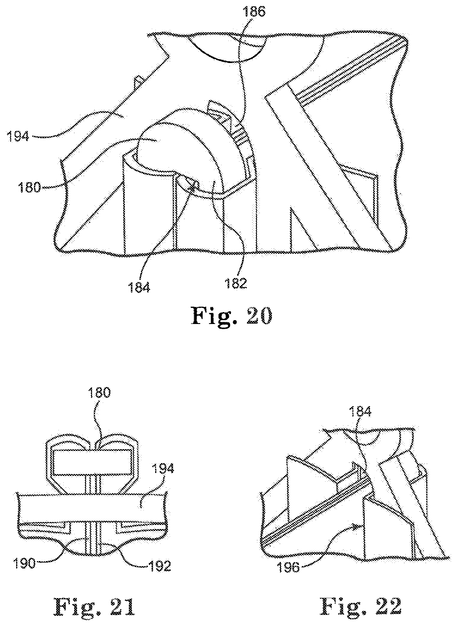
FIG. 20 is a perspective view of a "buckle" mechanism positioned relative to leaflets and a stent;
FIG. 21 is a top view of the portion of a stent, leaflets, and buckle mechanism illustrated in FIG. 20;
FIG. 22 is another perspective view of the portion of a stent illustrated in FIG. 20;
FIG. 23 is a perspective view of a "padded buckle" mechanism positioned relative to leaflets and a stent;
FIG. 24 is a top view of the portion of a stent, leaflets, and padded buckle mechanism illustrated in FIG. 23;
FIG. 25 is another perspective view of the portion of a stent illustrated in FIG. 23; and
FIG. 26 is a perspective view of another stent embodiment of the invention.
DETAILED DESCRIPTION
As referred to herein, the prosthetic heart valves used in accordance with the various devices and methods of heart valve delivery may include a wide variety of different configurations, such as a prosthetic heart valve having tissue leaflets or a synthetic heart valve having polymeric, metallic, or tissue-engineered leaflets, and can be specifically configured for replacing any heart valve. That is, while much of the description herein refers to replacement of aortic valves, the prosthetic heart valves of the invention can also generally be used for replacement of native mitral, pulmonic, or tricuspid valves, for use as a venous valve, or to replace a failed bioprosthesis, such as in the area of an aortic valve or mitral valve, for example.
Although each of the valves used with the delivery devices and methods described herein would typically include leaflets attached within an interior area of a stent, the leaflets are not shown in many of the illustrated embodiments for clarity purposes. In general, the stents described herein include a support structure comprising a number of strut or wire portions arranged relative to each other to provide a desired compressibility, strength, and leaflet attachment zone(s) to the heart valve. Other details on particular configurations of the stents of the invention are also described below; however, in general terms, stents of the invention are generally tubular support structures, and leaflets will be secured within the inner portion of the support structure to provide a valved stent. The leaflets can be formed from a variety of materials, such as autologous tissue, xenograph material, or synthetics as are known in the art. The leaflets may be provided as a homogenous, biological valve structure, such as a porcine, bovine, or equine valve. Alternatively, the leaflets can be provided independent of one another (e.g., bovine or equine pericardial leaflets) and subsequently assembled to the support structure of the stent. In another alternative, the stent and leaflets can be fabricated at the same time, such as may be accomplished using high strength nano-manufactured NiTi films of the type produced at Advanced Bio Prosthetic Surfaces Ltd. (ABPS) of San Antonio, Tex., for example. The support structures are generally configured to accommodate three leaflets; however, the replacement prosthetic heart valves of the invention can be configured to incorporate more or less than three leaflets.
In more general terms, the combination of a support structure with one or more leaflets can assume a variety of other configurations that differ from those shown and described, including any known prosthetic heart valve design. In certain embodiments of the invention, the support structure with leaflets utilize certain features of known expandable prosthetic heart valve configuration, whether balloon expandable, self-expanding, or unfurling (as described, for example, in U.S. Pat. Nos. 3,671,979; 4,056,854; 4,994,077; 5,332,402; 5,370,685; 5,397,351; 5,554,185; 5,855,601; and 6,168,614; U.S. Patent Application Publication No. 2004/0034411; Bonhoeffer P., et al., "Percutaneous Insertion of the Pulmonary Valve", Pediatric Cardiology, 2002; 39:1664-1669; Anderson H R, et al., "Transluminal Implantation of Artificial Heart Valves", EUR Heart J., 1992; 13:704-708; Anderson, J. R., et al., "Transluminal Catheter Implantation of New Expandable Artificial Cardiac Valve", BUR Heart J., 1990, 11: (Suppl) 224a; Hilbert S. L., "Evaluation of Explanted Polyurethane Trileaflet Cardiac Valve Prosthesis", J Thorac Cardiovascular Surgery, 1989; 94:419-29; Block P C, "Clinical and Hemodyamic Follow-Up After Percutaneous Aortic Valvuloplasty in the Elderly", The American Journal of Cardiology, Vol. 62, Oct. 1, 1998; Boudjemline, Y., "Steps Toward Percutaneous Aortic Valve Replacement", Circulation, 2002; 105:775-558; Bonhoeffer, P., "Transcatheter Implantation of a Bovine Valve in Pulmonary Position, a Lamb Study", Circulation, 2000:102:813-816; Boudjemline, Y., "Percutaneous Implantation of a Valve in the Descending Aorta In Lambs", EUR Heart J, 2002; 23:1045-1049; Kulkinski, D., "Future Horizons in Surgical Aortic Valve Replacement: Lessons Learned During the Early Stages of Developing a Transluminal Implantation Technique", ASAIO J, 2004; 50:364-68; the teachings of which are all incorporated herein by reference).
Orientation and positioning of the stents of the invention may be accomplished either by self-orientation of the stents (such as by interference between features of the stent and a previously implanted stent or valve structure) or by manual orientation of the stent to align its features with anatomical or previous bioprosthetic features, such as can be accomplished using fluoroscopic visualization techniques, for example. For example, when aligning the stents of the invention with native anatomical structures, they should be aligned so as to not block the coronary arteries, and native mitral or tricuspid valves should be aligned relative to the anterior leaflet and/or the trigones/commissures.
Some embodiments of the support structures of the stents described herein can be a series of wires or wire segments arranged so that they are capable of transitioning from a collapsed state to an expanded state. In some embodiments, a number of individual wires comprising the support structure can be formed of a metal or other material. These wires are arranged in such a way that a support structure allows for folding or compressing to a contracted state in which its internal diameter is greatly reduced from its internal diameter when it is in an expanded state. In its collapsed state, such a support structure with attached valves or leaflets can be mounted over a delivery device, such as a balloon catheter, for example. The support structure is configured so that it can be changed to its expanded state when desired, such as by the expansion of a balloon catheter. The delivery systems used for such a stent should be provided with degrees of rotational and axial orientation capabilities in order to properly position the stent at its desired location within the patient.
The wires of the support structure of the stents in other embodiments can alternatively be formed from a shape memory material such as a nickel titanium alloy (e.g., Nitinol). With this material, the support structure is self-expandable from a contracted state to an expanded state, such as by the application of heat, energy, and the like, or by the removal of external forces (e.g., compressive forces). This support structure can also be repeatedly compressed and re-expanded without damaging the structure of the stent. In addition, the support structure of such an embodiment may be laser cut from a single piece of material or may be assembled from a number of different components. For these types of stent structures, one example of a delivery system that can be used includes a catheter with a retractable sheath that covers the stent until it is to be deployed, at which point the sheath can be retracted to allow the stent to expand.
Referring now to the Figures, wherein the components are labeled with like numerals throughout the several Figures, and initially to FIGS. 1-4, an exemplary embodiment of a stent 10 is illustrated. Stent 10 may be referred to as a sub-coronary stent for use in replacement of the aortic valve in that it is preferably relatively short to enable stent placement below the coronaries. Stent 10 may be made of a self-expanding material, such as Nitinol, for example. In one embodiment, the stent 10 is generally tubular in shape and can be approximately 25 mm long, for example, although it can be longer or shorter than 25 mm, depending on the anatomy of the patient, the preferences of the surgeon, and other factors. The stent 10 includes multiple longitudinal or vertical wires 12 that extend generally parallel to a longitudinal axis 14 of the stent. The wires 12 are spaced from each other around the periphery of the generally tubular shape of the stent 10. Stent 10 further includes features to which tissue can be attached to make the stent into a valve, such as commissure attachment posts 16 that can be approximately 18 mm long, for example. The commissure attachment posts 16 each include two longitudinal wires that are spaced closer to each other than the spacing of the wires 12 from each other.
In this embodiment, stent 10 includes three commissure attachment posts 16, where each of the posts 16 is used as a connection location for one of the commissures of a tri-leaflet valve that will be attached thereto. Alternatively, more or less than three posts 16 can be provided for a valve having more or less than three leaflets, respectively. In addition to providing the structure for attachment of commissures, the posts 16 also provide additional stability to the stent 10. The wires 12 and posts 16 are preferably spaced at generally the same distance from each other around the periphery of the stent 10, although it is contemplated that some of the wires 12 and/or posts 16 can be spaced at different distances from each other around the periphery of the stent 10. Further, the specific illustrated embodiment of stent 10 includes two wires 12 positioned between two commissure attachment posts 16, although an alternate embodiment may include more or less wires 12 between adjacent commissure posts 16. However, the specific embodiment of stent 10 illustrated in FIGS. 1-4 comprises nine longitudinal structures around its periphery, including six longitudinal wires 12 and three commissure attachment posts 16.
Stent 10 further includes multiple V-shaped wire structures between a pair of wires 12 and/or between a wire 12 and an adjacent attachment post 16. As shown, the stent 10 includes three wires 18, 20, 22 that are longitudinally spaced from each other along the height of the stent 10 between each adjacent pair of wires 12 or between a wire 12 and an adjacent post 16. The size and shape of the wires 18, 20, 22 determines the spacing between adjacent longitudinal structures of the stent 10, which is generally uniform around the periphery of the stent, as discussed above. Although the stent 10 includes three of these V-shaped wires 18, 20, 22 that are spaced longitudinally from each other between adjacent vertical wire structures, there may be more or less than three V-shaped wires spaced longitudinally from each other.
Wires 18 are positioned at a first or outlet end 24 of the stent 10. A first end of each wire 18 extends from a first end 26 of an attachment post 16 or wire 12, and a second end of wire 18 extends from the first end 26 of an adjacent wire 12 or attachment post 16. In this way, a peak 28 of each wire 18 will be positioned generally in the center of the space between adjacent longitudinal wires, and will be directed toward a second or inlet end 30 of the stent 10. All or some of the wires 18 can be flared at least slightly outward relative to the outer tubular shape of the stent 10, thereby creating integrated flange structures that can be used to capture the native leaflets when the stent is implanted in a patient. Each wire 20 is spaced longitudinally from a corresponding wire 18, and each wire 22 is spaced longitudinally from a corresponding wire 20.
Additional wire structures 32 are positioned at the second end 30 of the stent 10 to correspond with each set of wires 18, 20, 22. In particular, each wire structure 32 is generally V-shaped, where the peak of each of the "V" structures is oriented in generally the same direction as the peaks of the wires 18, 20, 22. A first end of each wire structure 32 extends from a second end 34 of an attachment post 16 or wire 12, and a second end of wire structure 32 extends from the second end 34 of an adjacent wire 12 or attachment post 16. All or some of the wire structures 32 are flared at least slightly outward relative to the outer tubular shape of the stent 10. The amount and angle at which the wire structures extend relative to the tubular outer shape of the stent can be selected for capturing native patient anatomical features. In addition, this flare of the wire structures 32 can help to prevent or minimize leakage between the implant and the native annulus and/or to provide a physical and/or visual docking feature to secure the stent 10 against a wall of an opening in the heart to prevent migration of the stent, for example.
The stent 10 has a relatively high-density strut pattern to contain leaflets within the inner stent area during crimping of the stent. That is, while the exact number of longitudinal wires and V-shaped wires can vary somewhat from that illustrated in the Figures, it is preferable that the number of wires provided is sufficient to keep the leaflet material from becoming compressed and potentially damaged between the stent struts during the crimping process or from protruding beyond the periphery of the stent when it is in a crimped condition.
The first end 26 of all or some of the wires 12 and posts 16 can further include a loop or eyelet 36 that can be used for attachment to a delivery system and/or tissue valve, for example. The eyelets 36 can be in the same general plane as the outer tubular shape of the stent 10, or they can be directed at least slightly inward toward the central area of the stent or at least slightly outward relative to the outer tubular surface of the stent. The single-sided eyelet attachment end can be used in a resheathable delivery system for both antegrade and retrograde procedures, for example. Attachment end crown reducers can optionally be added to the stent to reduce the attachment crown number, although the stent would be lengthened at least slightly by such a modification.
FIG. 4 illustrates an exemplary laser cutting pattern that can be used to form the stent 10 out of a tube or single sheet of material. The stent 10 can alternatively be made from multiple components that are attached to each other and formed into a tubular shape. However, if the stent will be cut from a tube or single sheet of material as shown, the various structures will be designed so that they do not interfere with each other in the pattern.
FIG. 26 illustrates another exemplary embodiment of a stent 50 positioned for clarity on a mandrel, which also may be referred to as a sub-coronary stent in that it is preferably relatively short (e.g., 25 mm long) to enable stent placement below the coronary arteries in the aorta. This stent includes a number of the same features as the stent of FIGS. 1-4, although this stent 50 does not include the integrated petals shown and described above relative to stent 10. Rather, the V-shaped structures 52 at the outlet end of the stent 50 are generally in the same plane as the tubular outer shape of the stent 50 (i.e., the structures 52 are not flared outwardly). The stent 50 also includes eyelets 54 at the outlet end of the stent, which can be in the same general plane as the outer tubular shape of the stent 50, or they can be directed at least slightly inward or at least slightly outward relative to the outer tubular shape of the stent 50.
FIGS. 5-8 illustrate another exemplary embodiment of a stent 60, which is similar in structure to the stent 10 described above, including a wire structure with multiple commissure attachment posts 62. These posts 62 include two vertical struts that are spaced at least slightly from each other. These posts 62 further include multiple horizontal members 64 that are spaced from each other along the length or height of each post 62. The spaces or openings 66 that are created between the horizontal members 64 provide locations through which suture material, needles, and/or other fastening materials can be inserted for attachment of leaflet or valve material to the stent at the commissure posts. In addition, the horizontal members 64 can be used as defined anchoring points for the fastening materials. For example, a suture material can be inserted through a first opening 66 and then through another opening 66 in a predetermined pattern to stitch valve material to the commissure attachment posts 62. The horizontal members 64 can further be used as anchoring structures that keep sutures or other attachment mechanisms from moving vertically past a certain position along the attachment posts 62.
Another embodiment of a stent 80 is illustrated in FIGS. 9 and 10, which has a similar structure to stent structures described above relative to tubular stent constructions. Stent 80 further includes a scaling skirt 82 at its inlet end 84. The sealing skirt 82 can provide for improved sealing between the stent 80 and the anatomy in which the stent 80 is placed, such as the annulus of a valve, for example. The sealing skirt 82 can be configured to unfurl away from the inlet end 84 of the valve and into the delivery system that was used to deliver the stent 80, if desired. In this way, the material used to make the sealing skirt 82 does not increase the overall size of the stent 80 when it is crimped or compressed. The sealing skirt 82 can further be provided with radiopaque, echogenic properties or other visually detectable properties so that an operator can assess the proper positioning of the stent 80 in the patient's anatomy prior to releasing it from the delivery system.
A number of systems, components, and devices are described below for attachment of valve material (e.g., tissue leaflets) within the interior area of a stent structure. It is understood that the systems that are shown and described herein for this purpose can be used with stent configurations described above and/or other stent constructions.
In one exemplary embodiment, a tubular stent structure includes at least one commissure post, along with a first leaflet and a second leaflet. Leaflets are attached or sewn to the post using suture material. In this embodiment, a tissue "cushion" is provided on both sides of the commissure attachment post to help absorb and distribute stress away from the stitch points and to minimize tissue abrasion that can be caused without such protection. In this configuration, the leaflets 104, 106 can flex along the tissue and the leaflet/tissue seam line and the tissue cushion distributes stress from flexing during opening and closing of leaflets away from the suture points where leaflets are attached into the attachment post.
Another configuration and device that can be used in the attachment of valve material to a stent structure is shown and described relative to FIGS. 11-14. In particular, a relatively rigid "ladder" member 120 is provided to support the leaflet commissure area and transfer the line or point about which the leaflets 140 flex or bend to a location that is spaced from the suture line. In this way, the stresses can be more evenly distributed and durability of the valve improved. Ladder member 120 includes a relatively flat elongated plate 122 having multiple holes or openings 124 along its length. In order to minimize or prevent damage to the tissue of the valve, the corners and edges of the ladder member 120 are preferably rounded or smoothed. The holes 124 are preferably spaced from each other by a distance that corresponds with a desired stitching pattern that will be used to both secure the member 120 to the stent structure and attach the leaflets. It is further contemplated that the ladder member 120 is configured to match specific commissure features of the stent.
FIGS. 12 and 13 illustrate two ladder members 120 positioned relative to a portion of a stent 126 and portions of two leaflets. In particular, portions 128, 129 of adjacent leaflet commissures are secured in the space between two ladder members 120. The ladder members 120 are spaced from each other by a distance that allows the components to be securely fastened to each other, but that accommodates the thickness of the leaflets that are positioned between them. Additional material from the leaflets extends around the ends of the ladder members 120 between the edge of the ladder members 120 and the stent 126, then along the outwardly facing sides of the ladder members 120, such as is indicated by the reference number 130. This additional material provides for improved security in tissue attachment and also provides additional attachment locations.
Sutures 132 can be inserted through the tissue material to secure it to the ladder members 120, where one exemplary stitching pattern is illustrated in FIG. 15. An appropriate number of stitches should be made through the tissue material and ladder member 120 to securely attach the ladder members 120 to the leaflets. The same or a different suture material can be used to attach or position adjacent ladder members 120 relative to each other. Additional sutures or an extension of the sewing pattern can also be used to connect the ladder members 120 to the stent 126. The suture pattern can follow the holes in the ladder member 120 such that the ladder member 120 provides a template for sewing the leaflet tissue to the ladder members 120, or an alternate stitching pattern can be used. The leaflets can then flex against a long vertical edge 134 of each of the ladder members 120, thereby transferring the stress away from the attachment suture line.
FIG. 14 illustrates another tissue attachment arrangement that includes the use of two ladder members 120, as described above, along with additional protective layers 136. Each protective layer 136 can provide supplemental padding between a ladder and the adjacent leaflet material, and can also provide additional strength at the attachment sites. The protective layers 136 can be made of a material such as cloth, tissue, polymeric sheets, or the like. As shown, one protective layer 136 is used for each of the ladder members 120, with the protective layer 136 being positioned between each ladder member 120 and its corresponding leaflet 128, 129. Each protective layer 136 can wrap around at least a portion of the periphery of its corresponding ladder member 120, and in one embodiment will wrap around almost the entire periphery of the ladder members 120, as shown. Further, each protective layer 136 can extend along the entire length or height of its corresponding ladder 120, or it may extend along only a portion of the length of the ladder member 120. An exemplary pattern of stitching the components to each other and to the stent 126 is illustrated with the sutures 132 (shown as broken lines), although a different stitching pattern can instead be used.
Another configuration and device that can be used in the attachment of valve material to a stent structure is shown and described relative to FIGS. 15-17. In particular, a relatively rigid "slot bar" member 150 is provided to support the leaflet commissure area and transfer the line or point about which the leaflets flex or bend to a location that is spaced from the suture line. In this way, the stresses can be more evenly distributed. Slot bar member 150 includes a relatively flat elongated plate 152 having a longitudinal slot 156 extending along a portion of its length, and multiple holes or openings 154 along the length of the member 150 on both sides of the slot 156. Alternatively, one or both ends could be open and/or two separate portions can make up the slot bar member. In order to minimize or prevent damage to the tissue of the valve, the corners and edges of the slot bar member 150 are preferably rounded or smoothed. The holes 154 are preferably spaced from each other by a distance that corresponds with a desired stitching pattern that will be used to both secure the member 150 to the stent structure and the tissue to the slot bar. It is further contemplated that the slot bar member 150 is configured to match specific commissure features of the stent to which it will be attached. In addition, the width of the slot 156 is preferably selected based on the thickness of the leaflets that will be inserted through the slot 156. Thus, the slot 156 should be wide enough to accommodate two thicknesses of leaflet material; however, the slot 156 may be designed for more layers of material or for an optimized compression fit, if desired. In order to provide secure positioning of the tissue layers within the slot 156 and to minimize the potential for the tissue to be pulled from the slot 156, the slot should not be substantially wider than the thickness of the materials that will be positioned within it.
FIGS. 16-17 illustrate slot bar member 150 positioned relative to a portion of a stent 158 and portions of two leaflets 160, 162. In particular, the end portions of adjacent leaflet commissures 160, 162 are pulled through the slot 156 by a sufficient distance that the free edge of each of the leaflets extends at least slightly past the holes 154 on the flat side of the plate 152. This end portion of the leaflets 160, 162 will thereby be positioned between the slot bar member 150 and the stent to which they will be attached. In this way, the leaflets 160, 162 can be securely fastened to the slot bar member 150 and the stent 158. Sutures 164 can then be inserted through the tissue material to secure it to the slot bar member 150, where one exemplary stitching pattern is illustrated in FIGS. 16 and 17. The stitching pattern can follow the holes 154 in the slot bar member 150 such that the slot bar member 150 provides the template for sewing the leaflet tissue to the slot bar member 150, or an alternate stitching pattern can be used. The sutures 164 can thereby connect the slot bar member 150 to the leaflets 160, 162. Additional sutures or the same sutures can also be used to connect the slot bar member 150 to the stent 158. The leaflets 160, 162 can then flex over a long vertical edge 166 on each side of the slot bar member 150 during valve leaflet opening and closing, thereby transferring the stress away from the attachment suture line and increasing the durability of the valve.
FIGS. 18 and 19 illustrate another tissue attachment arrangement that includes the use of a slot bar member 150 of the type described above, along with additional protective members 170, 172. Protective members 170, 172 are positioned on opposite sides of the slot 156 of the slot bar member 150 so that each of the members 170, 172 can protect one of the leaflets 160, 162. Each protective member 170, 172 can provide additional padding or cushioning between one of the leaflets 160, 162 and the slot bar member 150 during opening and closing of the leaflets. The protective members 170, 172 can be made of a material such as cloth, tissue, polymeric sheets, or the like. Further, each protective member 170, 172 can extend along the entire length of its corresponding slot bar member 150, or it may extend along only a portion of the length of the slot bar member 150. An exemplary pattern of stitching the components to each other and to the stent 158 is illustrated with the schematic representation of a suture 164, although a different stitching pattern can instead be used. The suture material can be used to attach the excess tissue material to only the slot bar member 150, if desired. Alternatively, the protective members on the leaflet side of the slot bar member could be extended circumferentially beyond the slot bar member and attached to the stent (not shown). In this way, the leaflet would be prevented from contacting the suture material during opening of the valve reducing the potential for leaflet abrasion and tearing. In order to accommodate the thickness of the extra layers provided by the protective members 170, 172, the slot 156 should have an appropriate width.
Another configuration and device that can be used in the attachment of valve material to a stent structure is shown and described relative to FIGS. 20-22. In particular, a relatively rigid "buckle" member 180 is provided to support the leaflet commissure area and transfer the line or point about which the leaflets flex or bend to a location that is spaced away from the suture line. In this way, the stresses can be more evenly distributed increasing the durability of the valve. Buckle member 180 includes a relatively flat elongated plate 182 having a longitudinal slot 184 extending along a portion of its length. The slot could alternatively be open at either one or both ends of the plate. In order to minimize or prevent damage to the tissue of the valve, the corners and edges of the buckle member 180 are preferably rounded or smoothed. The width of the slot 184 is preferably selected based on the thickness of the layers of material that will be inserted through the slot 184. Thus, the slot 184 should be wide enough to accommodate the two thicknesses of leaflet material that will extend through it, as described below; however, the slot 184 may be designed for more layers of material or for an optimized compression fit, if desired. In order to provide secure positioning of the tissue layers within the slot 184 and to minimize the potential for the tissue to be pulled from the slot 184, the slot should not be substantially wider than the width of the material that will be positioned within it.
As shown in the Figures, the buckle member 180 is positioned on the opposite side of a stent 194 than the other embodiments discussed above (i.e., on the outer side of the stent structure rather than on the inner side of the stent structure). In this embodiment, the stent 194 has a vertical slot 186 in its commissure post that generally corresponds to the slot 184 in the buckle member 180. The end portions of two leaflets 190, 192 are pulled through the slot 186 in the stent commissure post, then through the slot 184 in the buckle member 180. The ends of the leaflets are then wrapped around the back side of the buckle member 180 and pulled back through the slot 186 in the commissure post in the opposite direction than the first insertion of the leaflets through this slot 186. The leaflets 190, 192 should continue to be pulled through the slot 186 by a sufficient distance that the free edge of each of the leaflets 190, 192 extends at least slightly past the structure of the stent in the internal area of the stent. With this arrangement, the leaflets 190, 192 will flex generally along a vertical line 196, which is the tissue that covers a vertical edge of the stent. In this embodiment, no sutures are required for attachment of the leaflets 190, 192 to the stent and/or the buckle member 180. Rather, the force on the commissure caused by the closing of the leaflets 190, 192 will cause the buckle member 180 to be pressed toward the stent, thereby compressing and locking the excess tissue material between the buckle member and the stent. This secures the commissure and prevents the tissue material of the leaflets from pulling out of the assembly.
FIGS. 23-25 illustrate another configuration and device for the attachment of valve material to a stent structure that includes the use of a buckle member 200 that is similar in design and operation to the buckle member 180 discussed above. In this embodiment, however, the buckle member 200 includes two longitudinal slots 202, 204 that are spaced from each other across the width of the buckle member 200, rather than a single, central slot. In this way, a first leaflet 206 can be pulled through a longitudinal slot 210 in the stent and through longitudinal slot 202 of the buckle member 200, and a second leaflet 208 can be pulled through a longitudinal slot 210 in the stent and through longitudinal slot 204 of the buckle member 200. The leaflets 206, 208 can then be wrapped around the back side of the buckle member 200, pulled back through the longitudinal slot 210 in the commissure post, and pulled through the slot by a sufficient distance that the leaflets can be secured to the stent without stitching, similar to the arrangement that uses the buckle member 180.
It is noted that in many of the stent embodiments shown and described herein, the aspect ratio of certain portions of the stent can be somewhat different from that shown. Further, stent embodiments described herein may be modified to include additional structure for attachment of tissue for the valve, such as the vertical stent posts described in many of the embodiments.
Delivering any balloon-expandable stents of the invention to the implantation location can be performed percutaneously. In general terms, this includes providing a transcatheter assembly, including a delivery catheter, a balloon catheter, and a guide wire. Some delivery catheters of this type are known in the art, and define a lumen within which the balloon catheter is received. The balloon catheter, in turn, defines a lumen within which the guide wire is slideably disposed. Further, the balloon catheter includes a balloon that is fluidly connected to an inflation source. It is noted that if the stent being implanted is the self-expanding type of stent, the balloon would not be needed and a sheath or other restraining means would be used for maintaining the stent in its compressed state until deployment of the stent, as described herein. In any case, for a balloon-expandable stent, the transcatheter assembly is appropriately sized for a desired percutaneous approach to the implantation location. For example, the transcatheter assembly can be sized for delivery to the heart valve via an opening at a carotid artery, a jugular vein, a sub-clavian vein, femoral artery or vein, or the like. Essentially, any percutaneous intercostals penetration can be made to facilitate use of the transcatheter assembly.
Prior to delivery, the stent is mounted over the balloon in a contracted state to be as small as possible without causing permanent deformation of the stent structure. As compared to the expanded state, the support structure is compressed onto itself and the balloon, thus defining a decreased inner diameter as compared to an inner diameter in the expanded state. While this description is related to the delivery of a balloon-expandable stent, the same basic procedures can also be applicable to a self-expanding stent, where the delivery system would not include a balloon, but would preferably include a sheath or some other type of configuration for maintaining the stent in a compressed condition until its deployment.
With the stent mounted to the balloon, the transcatheter assembly is delivered through a percutaneous opening (not shown) in the patient via the delivery catheter. The implantation location is located by inserting the guide wire into the patient, which guide wire extends from a distal end of the delivery catheter, with the balloon catheter otherwise retracted within the delivery catheter. The balloon catheter is then advanced distally from the delivery catheter along the guide wire, with the balloon and stent positioned relative to the implantation location. In an alternative embodiment, the stent is delivered to an implantation location via a minimally invasive surgical incision (i.e., non-percutaneously). In another alternative embodiment, the stent is delivered via open heart/chest surgery. In one embodiment of the stents of the invention, the stent includes a radiopaque, echogenic, or MRI visible material to facilitate visual confirmation of proper placement of the stent. Alternatively, other known surgical visual aids can be incorporated into the stent. The techniques described relative to placement of the stent within the heart can be used both to monitor and correct the placement of the stent in a longitudinal direction relative to the length of the anatomical structure in which it is positioned.
Once the stent is properly positioned, the balloon catheter is operated to inflate the balloon, thus transitioning the stent to an expanded state. Alternatively, where the support structure is formed of a shape memory material, the stent can self-expand to its expanded state.
The present invention has now been described with reference to several embodiments thereof. The foregoing detailed description and examples have been given for clarity of understanding only. No unnecessary limitations are to be understood therefrom. It will be apparent to those skilled in the art that many changes can be made in the embodiments described without departing from the scope of the invention. Thus, the scope of the present invention should not be limited to the structures described herein.
* * * * *
D00000
D00001
D00002
D00003
D00004
D00005
D00006
D00007
D00008
D00009
XML
uspto.report is an independent third-party trademark research tool that is not affiliated, endorsed, or sponsored by the United States Patent and Trademark Office (USPTO) or any other governmental organization. The information provided by uspto.report is based on publicly available data at the time of writing and is intended for informational purposes only.
While we strive to provide accurate and up-to-date information, we do not guarantee the accuracy, completeness, reliability, or suitability of the information displayed on this site. The use of this site is at your own risk. Any reliance you place on such information is therefore strictly at your own risk.
All official trademark data, including owner information, should be verified by visiting the official USPTO website at www.uspto.gov. This site is not intended to replace professional legal advice and should not be used as a substitute for consulting with a legal professional who is knowledgeable about trademark law.