Powering devices using low-current power sources
Ackley A
U.S. patent number 10,756,563 [Application Number 15/843,681] was granted by the patent office on 2020-08-25 for powering devices using low-current power sources. This patent grant is currently assigned to DATAMAX-O'NEIL CORPORATION. The grantee listed for this patent is Datamax-O'Neil Corporation. Invention is credited to H. Sprague Ackley.


| United States Patent | 10,756,563 |
| Ackley | August 25, 2020 |
Powering devices using low-current power sources
Abstract
Devices, systems, and methods may use a low current power source to charge an intermediate storage unit, providing sufficient electric power to perform various device functions. A voltage of the intermediate storage unit may be monitored using a voltage monitoring circuit, and a primary storage unit may be charged using current from the intermediate storage unit when the voltage of the intermediate storage unit meets a threshold.
| Inventors: | Ackley; H. Sprague (Seattle, WA) | ||||||||||
|---|---|---|---|---|---|---|---|---|---|---|---|
| Applicant: |
|
||||||||||
| Assignee: | DATAMAX-O'NEIL CORPORATION
(Altamonte Springs, FL) |
||||||||||
| Family ID: | 66814795 | ||||||||||
| Appl. No.: | 15/843,681 | ||||||||||
| Filed: | December 15, 2017 |
Prior Publication Data
| Document Identifier | Publication Date | |
|---|---|---|
| US 20190190304 A1 | Jun 20, 2019 | |
| Current U.S. Class: | 1/1 |
| Current CPC Class: | H02J 3/38 (20130101); H02J 7/34 (20130101); H02J 7/045 (20130101); H02J 7/35 (20130101); H02J 9/06 (20130101); H02J 7/345 (20130101); H02J 3/383 (20130101); H02J 7/00714 (20200101); Y02E 10/56 (20130101); Y04S 20/20 (20130101) |
| Current International Class: | H02J 7/04 (20060101); H02J 7/35 (20060101); H02J 3/38 (20060101); H02J 7/34 (20060101); H02J 9/06 (20060101) |
| Field of Search: | ;320/166,167 |
References Cited [Referenced By]
U.S. Patent Documents
| 5300875 | April 1994 | Tuttle |
| 6832725 | December 2004 | Gardiner et al. |
| 7128266 | October 2006 | Zhu et al. |
| 7159783 | January 2007 | Walczyk et al. |
| 7413127 | August 2008 | Ehrhart et al. |
| 7726575 | June 2010 | Wang et al. |
| 8148954 | April 2012 | Kehlstadt et al. |
| 8294969 | October 2012 | Plesko |
| 8317105 | November 2012 | Kotlarsky et al. |
| 8322622 | December 2012 | Liu |
| 8366005 | February 2013 | Kotlarsky et al. |
| 8371507 | February 2013 | Haggerty et al. |
| 8376233 | February 2013 | Van Horn et al. |
| 8381979 | February 2013 | Franz |
| 8390909 | March 2013 | Plesko |
| 8408464 | April 2013 | Zhu et al. |
| 8408468 | April 2013 | Horn et al. |
| 8408469 | April 2013 | Good |
| 8424768 | April 2013 | Rueblinger et al. |
| 8448863 | May 2013 | Xian et al. |
| 8457013 | June 2013 | Essinger et al. |
| 8459557 | June 2013 | Havens et al. |
| 8469272 | June 2013 | Kearney |
| 8474712 | July 2013 | Kearney et al. |
| 8479992 | July 2013 | Kotlarsky et al. |
| 8490877 | July 2013 | Kearney |
| 8517271 | August 2013 | Kotlarsky et al. |
| 8523076 | September 2013 | Good |
| 8528818 | September 2013 | Ehrhart et al. |
| 8544737 | October 2013 | Gomez et al. |
| 8548420 | October 2013 | Grunow et al. |
| 8550335 | October 2013 | Samek et al. |
| 8550354 | October 2013 | Gannon et al. |
| 8550357 | October 2013 | Kearney |
| 8556174 | October 2013 | Kosecki et al. |
| 8556176 | October 2013 | Van Horn et al. |
| 8556177 | October 2013 | Hussey et al. |
| 8559767 | October 2013 | Barber et al. |
| 8561895 | October 2013 | Gomez et al. |
| 8561903 | October 2013 | Sauerwein |
| 8561905 | October 2013 | Edmonds et al. |
| 8565107 | October 2013 | Pease et al. |
| 8571307 | October 2013 | Li et al. |
| 8579200 | November 2013 | Samek et al. |
| 8583924 | November 2013 | Caballero et al. |
| 8584945 | November 2013 | Wang et al. |
| 8587595 | November 2013 | Wang |
| 8587697 | November 2013 | Hussey et al. |
| 8588869 | November 2013 | Sauerwein et al. |
| 8590789 | November 2013 | Nahill et al. |
| 8596539 | December 2013 | Havens et al. |
| 8596542 | December 2013 | Havens et al. |
| 8596543 | December 2013 | Havens et al. |
| 8599271 | December 2013 | Havens et al. |
| 8599957 | December 2013 | Peake et al. |
| 8600158 | December 2013 | Li et al. |
| 8600167 | December 2013 | Showering |
| 8602309 | December 2013 | Longacre et al. |
| 8608053 | December 2013 | Meier et al. |
| 8608071 | December 2013 | Liu et al. |
| 8611309 | December 2013 | Wang et al. |
| 8615487 | December 2013 | Gomez et al. |
| 8621123 | December 2013 | Caballero |
| 8622303 | January 2014 | Meier et al. |
| 8628013 | January 2014 | Ding |
| 8628015 | January 2014 | Wang et al. |
| 8628016 | January 2014 | Winegar |
| 8629926 | January 2014 | Wang |
| 8630491 | January 2014 | Longacre et al. |
| 8635309 | January 2014 | Berthiaume et al. |
| 8636200 | January 2014 | Kearney |
| 8636212 | January 2014 | Nahill et al. |
| 8636215 | January 2014 | Ding et al. |
| 8636224 | January 2014 | Wang |
| 8638806 | January 2014 | Wang et al. |
| 8640958 | February 2014 | Lu et al. |
| 8640960 | February 2014 | Wang et al. |
| 8643717 | February 2014 | Li et al. |
| 8646692 | February 2014 | Meier et al. |
| 8646694 | February 2014 | Wang et al. |
| 8657200 | February 2014 | Ren et al. |
| 8659397 | February 2014 | Vargo et al. |
| 8668149 | March 2014 | Good |
| 8678285 | March 2014 | Kearney |
| 8678286 | March 2014 | Smith et al. |
| 8682077 | March 2014 | Longacre |
| D702237 | April 2014 | Oberpriller et al. |
| 8687282 | April 2014 | Feng et al. |
| 8692927 | April 2014 | Pease et al. |
| 8695880 | April 2014 | Bremer et al. |
| 8698949 | April 2014 | Grunow et al. |
| 8702000 | April 2014 | Barber et al. |
| 8717494 | May 2014 | Gannon |
| 8720783 | May 2014 | Biss et al. |
| 8723804 | May 2014 | Fletcher et al. |
| 8723904 | May 2014 | Marty et al. |
| 8727223 | May 2014 | Wang |
| 8740082 | June 2014 | Wilz |
| 8740085 | June 2014 | Furlong et al. |
| 8746563 | June 2014 | Hennick et al. |
| 8750445 | June 2014 | Peake et al. |
| 8752766 | June 2014 | Xian et al. |
| 8756059 | June 2014 | Braho et al. |
| 8757495 | June 2014 | Qu et al. |
| 8760563 | June 2014 | Koziol et al. |
| 8763909 | July 2014 | Reed et al. |
| 8777108 | July 2014 | Coyle |
| 8777109 | July 2014 | Oberpriller et al. |
| 8779898 | July 2014 | Havens et al. |
| 8781520 | July 2014 | Payne et al. |
| 8783573 | July 2014 | Havens et al. |
| 8789757 | July 2014 | Barten |
| 8789758 | July 2014 | Hawley et al. |
| 8789759 | July 2014 | Xian et al. |
| 8794520 | August 2014 | Wang et al. |
| 8794522 | August 2014 | Ehrhart |
| 8794525 | August 2014 | Amundsen et al. |
| 8794526 | August 2014 | Wang et al. |
| 8798367 | August 2014 | Ellis |
| 8807431 | August 2014 | Wang et al. |
| 8807432 | August 2014 | Van Horn et al. |
| 8810369 | August 2014 | Ackley |
| 8820630 | September 2014 | Qu et al. |
| 8822848 | September 2014 | Meagher |
| 8824692 | September 2014 | Sheerin et al. |
| 8824696 | September 2014 | Braho |
| 8842849 | September 2014 | Wahl et al. |
| 8844822 | September 2014 | Kotlarsky et al. |
| 8844823 | September 2014 | Fritz et al. |
| 8849019 | September 2014 | Li et al. |
| D716285 | October 2014 | Chaney et al. |
| 8851383 | October 2014 | Yeakley et al. |
| 8854633 | October 2014 | Laffargue |
| 8866963 | October 2014 | Grunow et al. |
| 8868421 | October 2014 | Braho et al. |
| 8868519 | October 2014 | Maloy et al. |
| 8868802 | October 2014 | Barten |
| 8868803 | October 2014 | Caballero |
| 8870074 | October 2014 | Gannon |
| 8879639 | November 2014 | Sauerwein |
| 8880426 | November 2014 | Smith |
| 8881983 | November 2014 | Havens et al. |
| 8881987 | November 2014 | Wang |
| 8903172 | December 2014 | Smith |
| 8908995 | December 2014 | Benos et al. |
| 8910870 | December 2014 | Li et al. |
| 8910875 | December 2014 | Ren et al. |
| 8914290 | December 2014 | Hendrickson et al. |
| 8914788 | December 2014 | Pettinelli et al. |
| 8915439 | December 2014 | Feng et al. |
| 8915444 | December 2014 | Havens et al. |
| 8916789 | December 2014 | Woodburn |
| 8918250 | December 2014 | Hollifield |
| 8918564 | December 2014 | Caballero |
| 8925818 | January 2015 | Kosecki et al. |
| 8939374 | January 2015 | Jovanovski et al. |
| 8942480 | January 2015 | Ellis |
| 8944313 | February 2015 | Williams et al. |
| 8944327 | February 2015 | Meier et al. |
| 8944332 | February 2015 | Harding et al. |
| 8950678 | February 2015 | Germaine et al. |
| D723560 | March 2015 | Zhou et al. |
| 8967468 | March 2015 | Gomez et al. |
| 8971346 | March 2015 | Sevier |
| 8976030 | March 2015 | Cunningham et al. |
| 8976368 | March 2015 | Akel et al. |
| 8978981 | March 2015 | Guan |
| 8978983 | March 2015 | Bremer et al. |
| 8978984 | March 2015 | Hennick et al. |
| 8985456 | March 2015 | Zhu et al. |
| 8985457 | March 2015 | Soule et al. |
| 8985459 | March 2015 | Kearney et al. |
| 8985461 | March 2015 | Gelay et al. |
| 8988578 | March 2015 | Showering |
| 8988590 | March 2015 | Gillet et al. |
| 8991704 | March 2015 | Hopper et al. |
| 8996194 | March 2015 | Davis et al. |
| 8996384 | March 2015 | Funyak et al. |
| 8998091 | April 2015 | Edmonds et al. |
| 9002641 | April 2015 | Showering |
| 9007368 | April 2015 | Laffargue et al. |
| 9010641 | April 2015 | Qu et al. |
| 9015513 | April 2015 | Murawski et al. |
| 9016576 | April 2015 | Brady et al. |
| D730357 | May 2015 | Fitch et al. |
| 9022288 | May 2015 | Nahill et al. |
| 9030964 | May 2015 | Essinger et al. |
| 9033240 | May 2015 | Smith et al. |
| 9033242 | May 2015 | Gillet et al. |
| 9036054 | May 2015 | Koziol et al. |
| 9037344 | May 2015 | Chamberlin |
| 9038911 | May 2015 | Xian et al. |
| 9038915 | May 2015 | Smith |
| D730901 | June 2015 | Oberpriller et al. |
| D730902 | June 2015 | Fitch et al. |
| 9047098 | June 2015 | Barten |
| 9047359 | June 2015 | Caballero et al. |
| 9047420 | June 2015 | Caballero |
| 9047525 | June 2015 | Barber |
| 9047531 | June 2015 | Showering et al. |
| 9049640 | June 2015 | Wang et al. |
| 9053055 | June 2015 | Caballero |
| 9053378 | June 2015 | Hou et al. |
| 9053380 | June 2015 | Xian et al. |
| 9057641 | June 2015 | Amundsen et al. |
| 9058526 | June 2015 | Powilleit |
| 9061527 | June 2015 | Tobin et al. |
| 9064165 | June 2015 | Havens et al. |
| 9064167 | June 2015 | Xian et al. |
| 9064168 | June 2015 | Todeschini et al. |
| 9064254 | June 2015 | Todeschini et al. |
| 9066032 | June 2015 | Wang |
| 9070032 | June 2015 | Corcoran |
| D734339 | July 2015 | Zhou et al. |
| D734751 | July 2015 | Oberpriller et al. |
| 9076459 | July 2015 | Braho et al. |
| 9079423 | July 2015 | Bouverie et al. |
| 9080856 | July 2015 | Laffargue |
| 9082023 | July 2015 | Feng et al. |
| 9084032 | July 2015 | Rautiola et al. |
| 9087250 | July 2015 | Coyle |
| 9092681 | July 2015 | Havens et al. |
| 9092682 | July 2015 | Wilz et al. |
| 9092683 | July 2015 | Koziol et al. |
| 9093141 | July 2015 | Liu |
| D737321 | August 2015 | Lee |
| 9098763 | August 2015 | Lu et al. |
| 9104929 | August 2015 | Todeschini |
| 9104934 | August 2015 | Li et al. |
| 9107484 | August 2015 | Chaney |
| 9111159 | August 2015 | Liu et al. |
| 9111166 | August 2015 | Cunningham |
| 9135483 | September 2015 | Liu et al. |
| 9137009 | September 2015 | Gardiner |
| 9141839 | September 2015 | Xian et al. |
| 9147096 | September 2015 | Wang |
| 9148474 | September 2015 | Skvoretz |
| 9158000 | October 2015 | Sauerwein |
| 9158340 | October 2015 | Reed et al. |
| 9158953 | October 2015 | Gillet et al. |
| 9159059 | October 2015 | Daddabbo et al. |
| 9165174 | October 2015 | Huck |
| 9171543 | October 2015 | Emerick et al. |
| 9183425 | November 2015 | Wang |
| 9189669 | November 2015 | Zhu et al. |
| 9195844 | November 2015 | Todeschini et al. |
| 9202458 | December 2015 | Braho et al. |
| 9208366 | December 2015 | Liu |
| 9208367 | December 2015 | Wang |
| 9219836 | December 2015 | Bouverie et al. |
| 9224022 | December 2015 | Ackley et al. |
| 9224024 | December 2015 | Bremer et al. |
| 9224027 | December 2015 | Van Horn et al. |
| D747321 | January 2016 | London et al. |
| 9230140 | January 2016 | Ackley |
| 9235553 | January 2016 | Fitch et al. |
| 9239950 | January 2016 | Fletcher |
| 9245492 | January 2016 | Ackley et al. |
| 9443123 | January 2016 | Hejl |
| 9248640 | February 2016 | Heng |
| 9250652 | February 2016 | London et al. |
| 9250712 | February 2016 | Todeschini |
| 9251411 | February 2016 | Todeschini |
| 9258033 | February 2016 | Showering |
| 9262633 | February 2016 | Todeschini et al. |
| 9262660 | February 2016 | Lu et al. |
| 9262662 | February 2016 | Chen et al. |
| 9269036 | February 2016 | Bremer |
| 9270782 | February 2016 | Hala et al. |
| 9274812 | March 2016 | Doren et al. |
| 9275388 | March 2016 | Havens et al. |
| 9277668 | March 2016 | Feng et al. |
| 9280693 | March 2016 | Feng et al. |
| 9286496 | March 2016 | Smith |
| 9297900 | March 2016 | Jiang |
| 9298964 | March 2016 | Li et al. |
| 9301427 | March 2016 | Feng et al. |
| D754205 | April 2016 | Nguyen et al. |
| D754206 | April 2016 | Nguyen et al. |
| 9304376 | April 2016 | Anderson |
| 9310609 | April 2016 | Rueblinger et al. |
| 9313377 | April 2016 | Todeschini et al. |
| 9317037 | April 2016 | Byford et al. |
| 9319548 | April 2016 | Showering et al. |
| D757009 | May 2016 | Oberpriller et al. |
| 9342723 | May 2016 | Liu et al. |
| 9342724 | May 2016 | McCloskey |
| 9361882 | June 2016 | Ressler et al. |
| 9365381 | June 2016 | Colonel et al. |
| 9373018 | June 2016 | Colavito et al. |
| 9375945 | June 2016 | Bowles |
| 9378403 | June 2016 | Wang et al. |
| D760719 | July 2016 | Zhou et al. |
| 9360304 | July 2016 | Chang et al. |
| 9383848 | July 2016 | Daghigh |
| 9384374 | July 2016 | Bianconi |
| 9390304 | July 2016 | Chang et al. |
| 9390596 | July 2016 | Todeschini |
| D762604 | August 2016 | Fitch et al. |
| 9411386 | August 2016 | Sauerwein |
| 9412242 | August 2016 | Van Horn et al. |
| 9418269 | August 2016 | Havens et al. |
| 9418270 | August 2016 | Van Volkinburg et al. |
| 9423318 | August 2016 | Lui et al. |
| D766244 | September 2016 | Zhou et al. |
| 9443222 | September 2016 | Singel et al. |
| 9454689 | September 2016 | McCloskey et al. |
| 9464885 | October 2016 | Lloyd et al. |
| 9465967 | October 2016 | Xian et al. |
| 9478113 | October 2016 | Xie et al. |
| 9478983 | October 2016 | Kather et al. |
| D771631 | November 2016 | Fitch et al. |
| 9481186 | November 2016 | Bouverie et al. |
| 9487113 | November 2016 | Schukalski |
| 9488986 | November 2016 | Solanki |
| 9489782 | November 2016 | Payne et al. |
| 9490540 | November 2016 | Davies et al. |
| 9491729 | November 2016 | Rautiola et al. |
| 9497092 | November 2016 | Gomez et al. |
| 9507974 | November 2016 | Todeschini |
| 9519814 | December 2016 | Cudzilo |
| 9521331 | December 2016 | Bessettes et al. |
| 9530038 | December 2016 | Xian et al. |
| D777166 | January 2017 | Bidwell et al. |
| 9558386 | January 2017 | Yeakley |
| 9572901 | February 2017 | Todeschini |
| 9606581 | March 2017 | Howe et al. |
| D783601 | April 2017 | Schulte et al. |
| D785617 | May 2017 | Bidwell et al. |
| D785636 | May 2017 | Oberpriller et al. |
| 9646189 | May 2017 | Lu et al. |
| 9646191 | May 2017 | Unemyr et al. |
| 9652648 | May 2017 | Ackley et al. |
| 9652653 | May 2017 | Todeschini et al. |
| 9656487 | May 2017 | Ho et al. |
| 9659198 | May 2017 | Giordano et al. |
| D790505 | June 2017 | Vargo et al. |
| D790546 | June 2017 | Zhou et al. |
| 9680282 | June 2017 | Hanenburg |
| 9697401 | July 2017 | Feng et al. |
| 9701140 | July 2017 | Alaganchetty et al. |
| 2003/0231001 | December 2003 | Bruning |
| 2005/0116544 | June 2005 | Hamel |
| 2006/0094425 | May 2006 | Mickle |
| 2007/0063048 | March 2007 | Havens et al. |
| 2009/0134221 | May 2009 | Zhu et al. |
| 2010/0026243 | February 2010 | Barrade et al. |
| 2010/0026248 | February 2010 | Barrade et al. |
| 2010/0177076 | July 2010 | Essinger et al. |
| 2010/0177080 | July 2010 | Essinger et al. |
| 2010/0177707 | July 2010 | Essinger et al. |
| 2010/0177749 | July 2010 | Essinger et al. |
| 2011/0169999 | July 2011 | Grunow et al. |
| 2011/0202554 | August 2011 | Powilleit et al. |
| 2011/0254510 | October 2011 | Chuang et al. |
| 2011/0254514 | October 2011 | Fleming |
| 2012/0111946 | May 2012 | Golant |
| 2012/0168512 | July 2012 | Kotlarsky et al. |
| 2012/0193423 | August 2012 | Samek |
| 2012/0194692 | August 2012 | Mers et al. |
| 2012/0203647 | August 2012 | Smith |
| 2012/0223141 | September 2012 | Good et al. |
| 2012/0256492 | October 2012 | Song |
| 2012/0256583 | October 2012 | Davis |
| 2012/0319487 | December 2012 | Shah |
| 2013/0043312 | February 2013 | Van Horn |
| 2013/0075168 | March 2013 | Amundsen et al. |
| 2013/0175341 | July 2013 | Kearney et al. |
| 2013/0175343 | July 2013 | Good |
| 2013/0221918 | August 2013 | Hill et al. |
| 2013/0257744 | October 2013 | Daghigh et al. |
| 2013/0257759 | October 2013 | Daghigh |
| 2013/0270346 | October 2013 | Xian et al. |
| 2013/0292475 | November 2013 | Kotlarsky et al. |
| 2013/0292477 | November 2013 | Hennick et al. |
| 2013/0293539 | November 2013 | Hunt et al. |
| 2013/0293540 | November 2013 | Laffargue et al. |
| 2013/0306728 | November 2013 | Thuries et al. |
| 2013/0306731 | November 2013 | Pedraro |
| 2013/0307964 | November 2013 | Bremer et al. |
| 2013/0308625 | November 2013 | Park et al. |
| 2013/0313324 | November 2013 | Koziol et al. |
| 2013/0332524 | December 2013 | Fiala et al. |
| 2013/0332996 | December 2013 | Fiala et al. |
| 2014/0001267 | January 2014 | Giordano et al. |
| 2014/0002828 | January 2014 | Laffargue et al. |
| 2014/0025584 | January 2014 | Liu et al. |
| 2014/0100813 | January 2014 | Showering |
| 2014/0034734 | February 2014 | Sauerwein |
| 2014/0036848 | February 2014 | Pease et al. |
| 2014/0039693 | February 2014 | Havens et al. |
| 2014/0049120 | February 2014 | Kohtz et al. |
| 2014/0049635 | February 2014 | Laffargue et al. |
| 2014/0061306 | March 2014 | Wu et al. |
| 2014/0063289 | March 2014 | Hussey et al. |
| 2014/0066136 | March 2014 | Sauerwein et al. |
| 2014/0067692 | March 2014 | Ye et al. |
| 2014/0070005 | March 2014 | Nahill et al. |
| 2014/0071840 | March 2014 | Venancio |
| 2014/0074746 | March 2014 | Wang |
| 2014/0076974 | March 2014 | Havens et al. |
| 2014/0078342 | March 2014 | Li et al. |
| 2014/0098792 | April 2014 | Wang et al. |
| 2014/0100774 | April 2014 | Showering |
| 2014/0103115 | April 2014 | Meier et al. |
| 2014/0104413 | April 2014 | McCloskey et al. |
| 2014/0104414 | April 2014 | McCloskey et al. |
| 2014/0104416 | April 2014 | Giordano et al. |
| 2014/0106725 | April 2014 | Sauerwein |
| 2014/0108010 | April 2014 | Maltseff et al. |
| 2014/0108402 | April 2014 | Gomez et al. |
| 2014/0108682 | April 2014 | Caballero |
| 2014/0110485 | April 2014 | Toa et al. |
| 2014/0114530 | April 2014 | Fitch et al. |
| 2014/0125853 | May 2014 | Wang |
| 2014/0125999 | May 2014 | Longacre et al. |
| 2014/0129378 | May 2014 | Richardson |
| 2014/0131443 | May 2014 | Smith |
| 2014/0131444 | May 2014 | Wang |
| 2014/0133379 | May 2014 | Wang et al. |
| 2014/0136208 | May 2014 | Maltseff et al. |
| 2014/0140585 | May 2014 | Wang |
| 2014/0152882 | June 2014 | Samek et al. |
| 2014/0158770 | June 2014 | Sevier et al. |
| 2014/0159869 | June 2014 | Zumsteg et al. |
| 2014/0166755 | June 2014 | Liu et al. |
| 2014/0166757 | June 2014 | Smith |
| 2014/0166759 | June 2014 | Liu et al. |
| 2014/0168787 | June 2014 | Wang et al. |
| 2014/0175165 | June 2014 | Havens et al. |
| 2014/0191684 | July 2014 | Valois |
| 2014/0191913 | July 2014 | Ge et al. |
| 2014/0197239 | July 2014 | Havens et al. |
| 2014/0197304 | July 2014 | Feng et al. |
| 2014/0204268 | July 2014 | Grunow et al. |
| 2014/0214631 | July 2014 | Hansen |
| 2014/0215228 | July 2014 | Choon |
| 2014/0217166 | August 2014 | Berthiaume et al. |
| 2014/0217180 | August 2014 | Liu |
| 2014/0231500 | August 2014 | Ehrhart et al. |
| 2014/0247315 | September 2014 | Marty et al. |
| 2014/0263493 | September 2014 | Amurgis et al. |
| 2014/0263645 | September 2014 | Smith et al. |
| 2014/0270196 | September 2014 | Braho et al. |
| 2014/0270229 | September 2014 | Braho |
| 2014/0278387 | September 2014 | DiGregorio |
| 2014/0282210 | September 2014 | Bianconi |
| 2014/0288933 | September 2014 | Braho et al. |
| 2014/0297058 | October 2014 | Barker et al. |
| 2014/0299665 | October 2014 | Barber et al. |
| 2014/0332590 | November 2014 | Wang et al. |
| 2014/0351317 | November 2014 | Smith et al. |
| 2014/0354412 | December 2014 | Ackely |
| 2014/0362184 | December 2014 | Jovanovski et al. |
| 2014/0363015 | December 2014 | Braho |
| 2014/0369511 | December 2014 | Sheerin et al. |
| 2014/0374483 | December 2014 | Lu |
| 2014/0374485 | December 2014 | Xian et al. |
| 2015/0001301 | January 2015 | Ouyang |
| 2015/0009338 | January 2015 | Laffargue et al. |
| 2015/0014416 | January 2015 | Kotlarsky et al. |
| 2015/0021397 | January 2015 | Rueblinger et al. |
| 2015/0028104 | January 2015 | Ma et al. |
| 2015/0029002 | January 2015 | Yeakley et al. |
| 2015/0032709 | January 2015 | Maloy et al. |
| 2015/0039309 | February 2015 | Braho et al. |
| 2015/0040378 | February 2015 | Saber et al. |
| 2015/0049347 | February 2015 | Laffargue et al. |
| 2015/0051992 | February 2015 | Smith |
| 2015/0053769 | February 2015 | Thuries et al. |
| 2015/0062366 | March 2015 | Liu et al. |
| 2015/0063215 | March 2015 | Wang |
| 2015/0088522 | March 2015 | Hendrickson et al. |
| 2015/0096872 | April 2015 | Woodburn |
| 2015/0100196 | April 2015 | Hollifield |
| 2015/0115035 | April 2015 | Meier et al. |
| 2015/0127791 | May 2015 | Kosecki et al. |
| 2015/0128116 | May 2015 | Chen et al. |
| 2015/0133047 | May 2015 | Smith et al. |
| 2015/0134470 | May 2015 | Hejl et al. |
| 2015/0136851 | May 2015 | Harding et al. |
| 2015/0142492 | May 2015 | Kumar |
| 2015/0144692 | May 2015 | Hejl |
| 2015/0144698 | May 2015 | Teng et al. |
| 2015/0149946 | May 2015 | Benos et al. |
| 2015/0161429 | June 2015 | Xian |
| 2015/0178523 | June 2015 | Gelay et al. |
| 2015/0178537 | June 2015 | El et al. |
| 2015/0178685 | June 2015 | Krumel et al. |
| 2015/0181109 | June 2015 | Gillet et al. |
| 2015/0186703 | July 2015 | Chen et al. |
| 2015/0199957 | July 2015 | Funyak et al. |
| 2015/0210199 | July 2015 | Payne |
| 2015/0212565 | July 2015 | Murawski et al. |
| 2015/0213647 | July 2015 | Laffargue et al. |
| 2015/0220753 | August 2015 | Zhu et al. |
| 2015/0220901 | August 2015 | Gomez et al. |
| 2015/0227189 | August 2015 | Davis et al. |
| 2015/0236984 | August 2015 | Sevier |
| 2015/0239348 | August 2015 | Chamberlin |
| 2015/0242658 | August 2015 | Nahill et al. |
| 2015/0248572 | September 2015 | Soule et al. |
| 2015/0254485 | September 2015 | Feng et al. |
| 2015/0261643 | September 2015 | Caballero et al. |
| 2015/0264624 | September 2015 | Wang et al. |
| 2015/0268971 | September 2015 | Barten |
| 2015/0269402 | September 2015 | Barber et al. |
| 2015/0288689 | October 2015 | Todeschini et al. |
| 2015/0288896 | October 2015 | Wang |
| 2015/0310243 | October 2015 | Ackley |
| 2015/0310244 | October 2015 | Xian et al. |
| 2015/0310389 | October 2015 | Crimm et al. |
| 2015/0312780 | October 2015 | Wang et al. |
| 2015/0327012 | November 2015 | Bian et al. |
| 2016/0014251 | January 2016 | Hejl |
| 2016/0025697 | January 2016 | Alt et al. |
| 2016/0026838 | January 2016 | Gillet et al. |
| 2016/0026839 | January 2016 | Qu et al. |
| 2016/0040982 | February 2016 | Li et al. |
| 2016/0042241 | February 2016 | Todeschini |
| 2016/0057230 | February 2016 | Todeschini et al. |
| 2016/0062473 | March 2016 | Bouchat et al. |
| 2016/0092805 | March 2016 | Geisler et al. |
| 2016/0101936 | April 2016 | Chamberlin |
| 2016/0102975 | April 2016 | McCloskey et al. |
| 2016/0104019 | April 2016 | Todeschini et al. |
| 2016/0104274 | April 2016 | Jovanovski et al. |
| 2016/0109219 | April 2016 | Ackley et al. |
| 2016/0109220 | April 2016 | Laffargue |
| 2016/0109224 | April 2016 | Thuries et al. |
| 2016/0112631 | April 2016 | Ackley et al. |
| 2016/0112643 | April 2016 | Laffargue et al. |
| 2016/0117627 | April 2016 | Raj et al. |
| 2016/0124516 | May 2016 | Schoon et al. |
| 2016/0125217 | May 2016 | Todeschini |
| 2016/0125342 | May 2016 | Miller et al. |
| 2016/0133253 | May 2016 | Braho et al. |
| 2016/0171597 | June 2016 | Todeschini |
| 2016/0171666 | June 2016 | McCloskey |
| 2016/0171720 | June 2016 | Todeschini |
| 2016/0171775 | June 2016 | Todeschini et al. |
| 2016/0171777 | June 2016 | Todeschini et al. |
| 2016/0174674 | June 2016 | Oberpriller et al. |
| 2016/0178479 | June 2016 | Goldsmith |
| 2016/0178685 | June 2016 | Young et al. |
| 2016/0178707 | June 2016 | Young et al. |
| 2016/0179132 | June 2016 | Harr et al. |
| 2016/0179143 | June 2016 | Bidwell et al. |
| 2016/0179368 | June 2016 | Roeder |
| 2016/0179378 | June 2016 | Kent et al. |
| 2016/0180130 | June 2016 | Bremer |
| 2016/0180133 | June 2016 | Oberpriller et al. |
| 2016/0180136 | June 2016 | Meier et al. |
| 2016/0180594 | June 2016 | Todeschini |
| 2016/0180663 | June 2016 | McMahan et al. |
| 2016/0180678 | June 2016 | Ackley et al. |
| 2016/0180713 | June 2016 | Bernhardt et al. |
| 2016/0185136 | June 2016 | Ng et al. |
| 2016/0185291 | June 2016 | Chamberlin |
| 2016/0186926 | June 2016 | Oberpriller et al. |
| 2016/0188861 | June 2016 | Todeschini |
| 2016/0188939 | June 2016 | Sailors et al. |
| 2016/0188940 | June 2016 | Lu et al. |
| 2016/0188941 | June 2016 | Todeschini et al. |
| 2016/0188942 | June 2016 | Good et al. |
| 2016/0188943 | June 2016 | Linwood |
| 2016/0188944 | June 2016 | Wilz et al. |
| 2016/0189076 | June 2016 | Mellott et al. |
| 2016/0189087 | June 2016 | Morton et al. |
| 2016/0189088 | June 2016 | Pecorari et al. |
| 2016/0189092 | June 2016 | George et al. |
| 2016/0189284 | June 2016 | Mellott et al. |
| 2016/0189288 | June 2016 | Todeschini |
| 2016/0189366 | June 2016 | Chamberlin et al. |
| 2016/0189443 | June 2016 | Smith |
| 2016/0189447 | June 2016 | Valenzuela |
| 2016/0189489 | June 2016 | Au et al. |
| 2016/0191684 | June 2016 | DiPiazza et al. |
| 2016/0192051 | June 2016 | DiPiazza et al. |
| 2016/0125873 | July 2016 | Braho et al. |
| 2016/0202951 | July 2016 | Pike et al. |
| 2016/0202958 | July 2016 | Zabel et al. |
| 2016/0202959 | July 2016 | Doubleday et al. |
| 2016/0203021 | July 2016 | Pike et al. |
| 2016/0203429 | July 2016 | Mellott et al. |
| 2016/0203797 | July 2016 | Pike et al. |
| 2016/0203820 | July 2016 | Zabel et al. |
| 2016/0204623 | July 2016 | Haggert et al. |
| 2016/0204636 | July 2016 | Allen et al. |
| 2016/0204638 | July 2016 | Miraglia |
| 2016/0316190 | July 2016 | McCloskey et al. |
| 2016/0227912 | August 2016 | Oberpriller et al. |
| 2016/0232891 | August 2016 | Pecorari |
| 2016/0292477 | October 2016 | Bidwell |
| 2016/0294779 | October 2016 | Yeakley et al. |
| 2016/0306769 | October 2016 | Kohtz et al. |
| 2016/0314276 | October 2016 | Sewell et al. |
| 2016/0314294 | October 2016 | Kubler et al. |
| 2016/0323310 | November 2016 | Todeschini et al. |
| 2016/0325677 | November 2016 | Fitch et al. |
| 2016/0327614 | November 2016 | Young et al. |
| 2016/0327930 | November 2016 | Charpentier et al. |
| 2016/0328762 | November 2016 | Pape |
| 2016/0330218 | November 2016 | Hussey et al. |
| 2016/0343163 | November 2016 | Venkatesha et al. |
| 2016/0343176 | November 2016 | Ackley |
| 2016/0364914 | December 2016 | Todeschini |
| 2016/0370220 | December 2016 | Ackley et al. |
| 2016/0372282 | December 2016 | Bandringa |
| 2016/0373847 | December 2016 | Vargo et al. |
| 2016/0377414 | December 2016 | Thuries et al. |
| 2016/0377417 | December 2016 | Jovanovski et al. |
| 2017/0010141 | January 2017 | Ackley |
| 2017/0010328 | January 2017 | Mullen et al. |
| 2017/0010780 | January 2017 | Waldron et al. |
| 2017/0016714 | January 2017 | Laffargue et al. |
| 2017/0018094 | January 2017 | Todeschini |
| 2017/0046603 | February 2017 | Lee et al. |
| 2017/0047864 | February 2017 | Stang et al. |
| 2017/0053146 | February 2017 | Liu et al. |
| 2017/0053147 | February 2017 | Geramine et al. |
| 2017/0053647 | February 2017 | Nichols et al. |
| 2017/0055606 | March 2017 | Xu et al. |
| 2017/0060316 | March 2017 | Larson |
| 2017/0061961 | March 2017 | Nichols et al. |
| 2017/0064634 | March 2017 | Van Horn et al. |
| 2017/0083730 | March 2017 | Feng et al. |
| 2017/0091502 | March 2017 | Furlong et al. |
| 2017/0091706 | March 2017 | Lloyd et al. |
| 2017/0091741 | March 2017 | Todeschini |
| 2017/0091904 | March 2017 | Ventress |
| 2017/0092908 | March 2017 | Chaney |
| 2017/0094238 | March 2017 | Germaine et al. |
| 2017/0098947 | April 2017 | Wolski |
| 2017/0100949 | April 2017 | Celinder et al. |
| 2017/0108838 | April 2017 | Todeschini et al. |
| 2017/0108895 | April 2017 | Chamberlin et al. |
| 2017/0118355 | April 2017 | Wong et al. |
| 2017/0123598 | May 2017 | Phan et al. |
| 2017/0124369 | May 2017 | Rueblinger et al. |
| 2017/0124396 | May 2017 | Todeschini et al. |
| 2017/0124687 | May 2017 | McCloskey et al. |
| 2017/0126873 | May 2017 | McGary et al. |
| 2017/0126904 | May 2017 | d'Armancourt et al. |
| 2017/0139012 | May 2017 | Smith |
| 2017/0140329 | May 2017 | Bernhardt et al. |
| 2017/0140731 | May 2017 | Smith |
| 2017/0147847 | May 2017 | Berggren et al. |
| 2017/0150124 | May 2017 | Thuries |
| 2017/0169198 | June 2017 | Nichols |
| 2017/0171035 | June 2017 | Lu et al. |
| 2017/0171703 | June 2017 | Maheswaranathan |
| 2017/0171803 | June 2017 | Maheswaranathan |
| 2017/0180359 | June 2017 | Wolski et al. |
| 2017/0180577 | June 2017 | Nguon et al. |
| 2017/0181299 | June 2017 | Shi et al. |
| 2017/0190192 | July 2017 | Delario et al. |
| 2017/0193432 | July 2017 | Bernhardt |
| 2017/0193461 | July 2017 | Jonas et al. |
| 2017/0193727 | July 2017 | Van Horn et al. |
| 2017/0199266 | July 2017 | Rice et al. |
| 2017/0200108 | July 2017 | Au et al. |
| 2017/0200275 | July 2017 | McCloskey et al. |
| 2017/0201003 | July 2017 | Ackley et al. |
| 3190547 | Jul 2017 | EP | |||
| 253845 | Aug 2016 | GB | |||
| 2008010890 | Jan 2008 | WO | |||
| 2013163789 | Nov 2013 | WO | |||
Other References
|
European Search Report for EP Application No. 1715024.6; dated May 30, 2017; 9 pages. cited by applicant . Great Britain Combined Search and Examination Report in related Application No. GB1600103.4 [Published as GB2535845], dated Jun. 23, 2016; 7 pages. cited by applicant. |
Primary Examiner: Tso; Edward
Assistant Examiner: Omar; Ahmed H
Attorney, Agent or Firm: Alston & Bird LLP
Claims
It is intended that the scope of the present invention be defined by the following claims and their equivalents:
1. A method of providing electric power to an electric component in a device, the method comprising: receiving electric current from one or more low current power sources connected to a device; charging an intermediate storage unit in the device with the electric current from the one or more low current power sources; monitoring a voltage of the intermediate storage unit using a voltage monitoring circuit communicatively coupled to a processor; charging a primary storage unit using electric current from the intermediate storage unit when the processor ascertains that the voltage of the intermediate storage unit meets or exceeds a threshold, the intermediate storage unit discharging varying quantities of the electric current at varying time intervals to the primary storage unit based on the functions assigned to the device; and providing the electric current from the primary storage unit to a component, the component using the electric current to cause the device to perform the functions.
2. The method of claim 1, wherein the device comprises a thermal printer and wherein the component comprises a printing mechanism.
3. The method of claim 1, wherein the component receives electrical power solely from the primary storage unit.
4. The method of claim 1, wherein the intermediate storage unit comprises at least one capacitor and/or at least one supercapacitor.
5. The method of claim 1, wherein the primary storage unit comprises a rechargeable battery.
6. The method of claim 1, wherein the threshold comprises a voltage range of the intermediate storage unit, the range falling between a lower voltage sufficient for efficiently discharging current to the primary storage unit and an upper voltage sufficient for further charging of the intermediate storage to be inefficient.
7. The method of claim 1, wherein the component typically receives intermittent use at time intervals matching or exceeding a positive multiple of a time constant, tau, comprising a resistance of charging the intermediate storage unit multiplied by a capacitance of the intermediate storage unit, and wherein the intermediate storage unit is configured to accumulate a voltage over the positive multiple of the time constant which voltage exceeds the charge consumed by a typical instance of use of the component.
8. The method of claim 1, wherein the intermediate storage unit comprises a plurality of capacitors and/or supercapacitors in series.
9. The method of claim 1, wherein the intermediate storage unit comprises a plurality of capacitors and/or supercapacitors in parallel.
10. A device configured to use electric current from one or more low current power sources to perform a function, the device comprising: an intermediate storage unit configured to receive electric current from one or more low current power sources, the electric current from the one or more low current power sources at least partially charging the intermediate storage unit; a voltage monitor circuit communicatively coupled to a processor, the processor configured to monitor a voltage of the intermediate storage unit; a primary storage unit configured to receive electric current from the intermediate storage unit when the processor ascertains that the voltage of the intermediate storage unit meets or exceeds a threshold, the intermediate storage unit configured to then discharge varying quantities of the electric current at varying time intervals to the primary storage unit based on the functions assigned to the device, and the electric current from the intermediate storage unit at least partially charging the primary storage unit; and a component configured to use the electric current from the primary storage unit to perform the functions, the primary storage unit configured to provide the electric current to the component.
11. The device of claim 10, wherein the device comprises a thermal printer and wherein the component comprises a printing mechanism.
12. The device of claim 10, wherein the component receives electrical power solely from the primary storage unit.
13. The device of claim 10, wherein the intermediate storage unit comprises at least one capacitor and/or at least one supercapacitor.
14. The device of claim 10, wherein the primary storage unit comprises a rechargeable battery.
15. The device of claim 10, wherein the threshold comprises a voltage range of the intermediate storage unit, the range falling between a lower voltage sufficient for efficiently discharge current to the primary storage unit and an upper voltage sufficient for further charging of the intermediate storage to be inefficient.
16. The device of claim 10, wherein the component typically receives intermittent use at time intervals matching or exceeding a positive multiple of a time constant, tau, comprising a resistance of charging the intermediate storage unit multiplied by a capacitance of the intermediate storage unit, and wherein the intermediate storage unit is configured to accumulate a voltage over the positive multiple of the time constant which voltage exceeds the charge consumed by a typical instance of use of the component.
17. The device of claim 10, wherein the intermediate storage unit comprises a plurality of capacitors and/or supercapacitors, at least a portion of the plurality being arranged in series and/or in parallel.
18. A method of providing power to a component in a device, the method comprising: receiving electric current from one or more low current power sources connected to a device; charging an intermediate storage unit in the device with the electric current from the one or more low current power sources; monitoring a voltage of the intermediate storage unit using a voltage monitoring circuit communicatively coupled to a processor; charging a primary storage unit using electric current from the intermediate storage unit when the processor ascertains that the voltage of the intermediate storage unit meets or exceeds a charge consumed by a typical instance of use of a component in the device, the intermediate storage unit discharging varying quantities of the electric current at varying time intervals to the primary storage unit based on the functions assigned to the device; and providing the electric current from the primary storage unit to the component, the component using the electric current to cause the device to perform the functions.
19. The method of claim 1, wherein the one or more low current power sources include one or more of a powered Ethernet cable, a solar cell, electric field associated with wireless communication, magnetic field associated with wireless communication, or a powered Universal Serial Bus.
20. The device of claim 10, wherein the one or more low current power sources include one or more of a powered Ethernet cable, a solar cell, electric field associated with wireless communication, magnetic field associated with wireless communication, or a powered Universal Serial Bus.
Description
FIELD OF THE INVENTION
The present disclosure relates to devices, systems, and methods that use a low current power source to perform various device functions, including devices, systems, and methods that use a lower current power source to charge an intermediate storage unit, providing sufficient electric power to perform various device functions.
BACKGROUND
Conventional battery powered devices are stationed throughout facilities, often in locations without an electrical outlet nearby. Such devices require periodic recharging or replacement of batteries. Some devices rely on battery power alone. Recharging or replacing batteries tends to be inconvenient, particularly when there is not an electrical outlet nearby for a charging station. For example, distributed computing systems may be implemented in a wide variety of settings, including hospitals and other healthcare facilities, and supply chain distribution facilities and resources. Distributed computing systems commonly include points of use without an electrical outlet nearby. Inconveniences of recharging or replacing batteries typically limits the feasibility of deploying battery powered devices in remote or infrequently occupied locations. Workers may be inconsistent or unreliable about maintaining adequately charged batteries in distributed devices. Additionally, some devices may remain unattended or inaccessible for extended periods of time.
Low current power sources such as those available from a powered Ethernet cable or a radio frequency field can be "harvested" to supplement a device's power consumption from a battery by using a trickle flow of electricity from such low current power source. Various approaches to harvesting a trickle flow of electricity from low current power sources are discussed in the art. However, existing approaches are generally insufficient to provide a substantive practical benefit, such as powering a device or recharging batteries. Conventional rechargeable batteries require a significant potential difference to reverse the chemical reactions used to store electrical energy. Capacitors or super-capacitors are an alternative to rechargeable batteries for storing power; however, capacitors and even super-capacitors are less effective at storing a charge for extended periods of time compared with batteries. Therefore, there exist a need for further improved devices, systems, and methods that use electricity harvested from a low current power source to charge an intermediate storage unit, providing sufficient electric power to perform various device functions.
SUMMARY
Accordingly, in one aspect, the present disclosure embraces a method of providing electric power to an electric component in a device. In one embodiment, the method includes receiving electric current from one or more low current power sources (e.g., a powered Ethernet cable connected to a device or a radio frequency field), charging an intermediate storage unit in the device with the electric current from the low current power source, monitoring a voltage of the intermediate storage unit using a voltage monitoring circuit communicatively coupled to a processor, charging a primary storage unit using electric current from the intermediate storage unit when the processor ascertains that the voltage of the intermediate storage unit meets or exceeds a threshold (the intermediate storage unit discharging the electric current to the primary storage unit), and providing electric current from the primary storage unit to a component, allowing the component using the electric current to cause the device to perform a function.
The intermediate storage unit may include at least one capacitor and/or at least one supercapacitor, such as a plurality of capacitors and/or supercapacitors in series or parallel. The primary storage unit may include a rechargeable battery and/or a supercapacitor, such as a plurality of supercapacitors and/or rechargeable batteries in series or parallel.
The device may be a printer, such as a thermal printer, and the component may be or may include a printing mechanism. The printing mechanism may be a printhead or other printing component. The printhead may be a thermal printhead. Other devices and components will be apparent and are within the spirit and scope of the present disclosure, many of which are described herein. In some embodiments, the component may receive electric power solely from the primary storage unit.
The threshold may include or depend on a voltage range of the intermediate storage unit. The range may fall between a lower voltage sufficient for efficiently discharging current to the primary storage unit and an upper voltage sufficient for further charging of the intermediate storage to be inefficient.
In another aspect, the present disclosure embraces a device configured to use electric current from one or more low current power sources to perform one or more functions. The low current power source may be a powered Ethernet cable, or an electric field or magnetic field associated with a wireless communications or broadcast signal. In some embodiments the low current power source may be an electric field or magnetic field associated with FM or AM radio waves. In some embodiments, the device includes an intermediate storage unit and a primary storage unit. The intermediate storage unit may be configured to receive electric current from the low current power source. The primary storage unit may be configured to receive electric current from the intermediate storage unit. The electric current from the intermediate storage unit may at least partially charge the primary storage unit.
An exemplary device may include a voltage monitor circuit communicatively coupled to a processor, and the processor may be configured to monitor a voltage of the intermediate storage unit. The primary storage unit may be configured to receive electric current from the intermediate storage unit when the processor ascertains that the voltage of the intermediate storage unit meets or exceeds a threshold. The device may further include one or more components configured to use electric current from the primary storage unit to perform a function. The primary storage unit may be configured to provide the electric current to the component.
In some embodiments, the device or the one or more components typically receive intermittent use at time intervals matching or exceeding a positive multiple of a time constant, .tau. (tau). The time constant depends on a resistance of charging the intermediate storage unit multiplied by a capacitance of the intermediate storage unit. The intermediate storage unit may accumulate a voltage over the positive multiple of the time constant, that exceeds the charge consumed by a typical instance of use of the component.
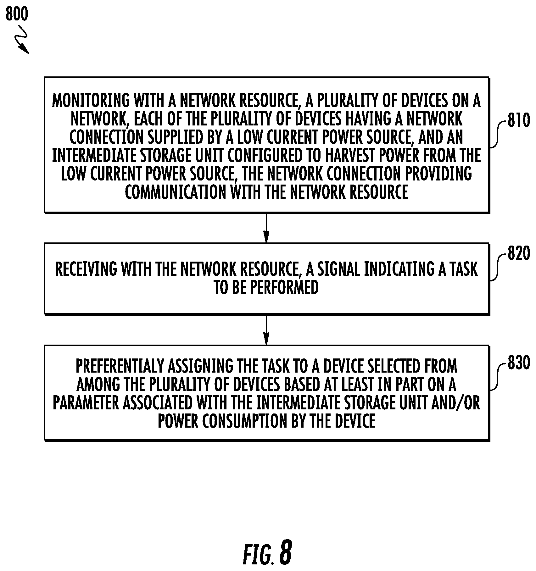
In another aspect, the present disclosure embraces a distributed computing system that includes a plurality of devices in communication with at least one network resource on a computer network. The network resource may be configured to monitor the plurality of devices on the computer network, receive a signal indicating a task to be performed; and preferentially assigning the task to a device selected from among the plurality of devices. Such device may be selected based at least in part on a threshold or parameter associated with the intermediate storage unit and/or power consumption by the device.
The plurality of devices may typically receive intermittent use at time intervals matching or exceeding a positive multiple of a time constant .tau. (tau). The time constant depends on a resistance of charging the respective intermediate storage unit multiplied by a capacitance of the respective intermediate storage unit. The respective intermediate storage units may be configured to accumulate a voltage over the positive multiple of the time constant which voltage exceeds the electrical power consumed by a typical instance of use of the respective component.
The foregoing summary is illustrative only, and is not intended to be in any way limiting. In addition to the illustrative features and embodiments described above, further aspects, features, and embodiments will become apparent by references to the following drawings, the detailed description set forth below, and the claims.
BRIEF DESCRIPTION OF THE DRAWINGS
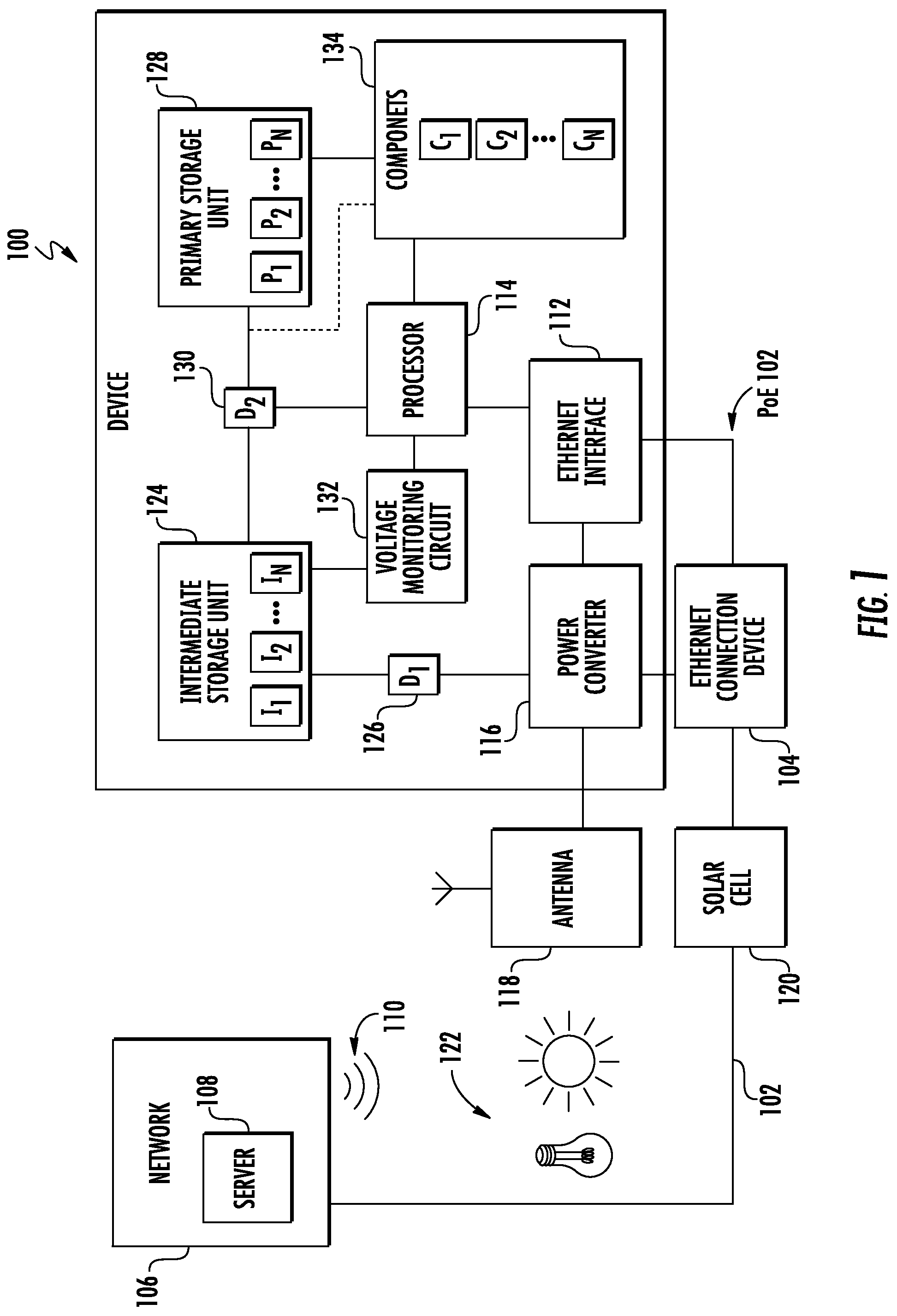
FIG. 1 schematically depicts an exemplary device configured to harvest energy from a low current power source.
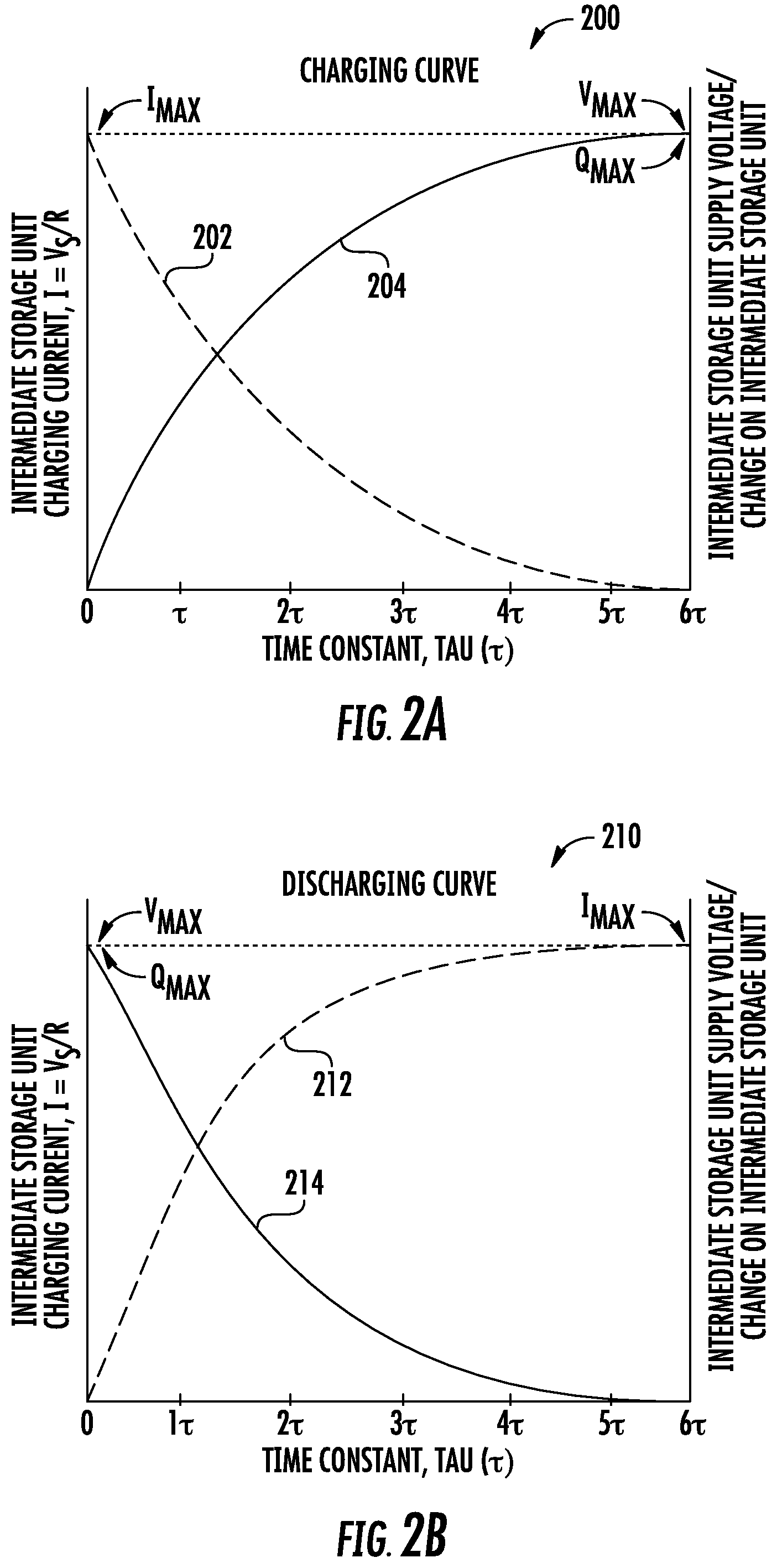
FIGS. 2A and 2B respectively depict exemplary charge and discharge curves for an intermediate storage unit.
FIG. 3 shows an exemplary method of providing electric power to an electric component in a device.
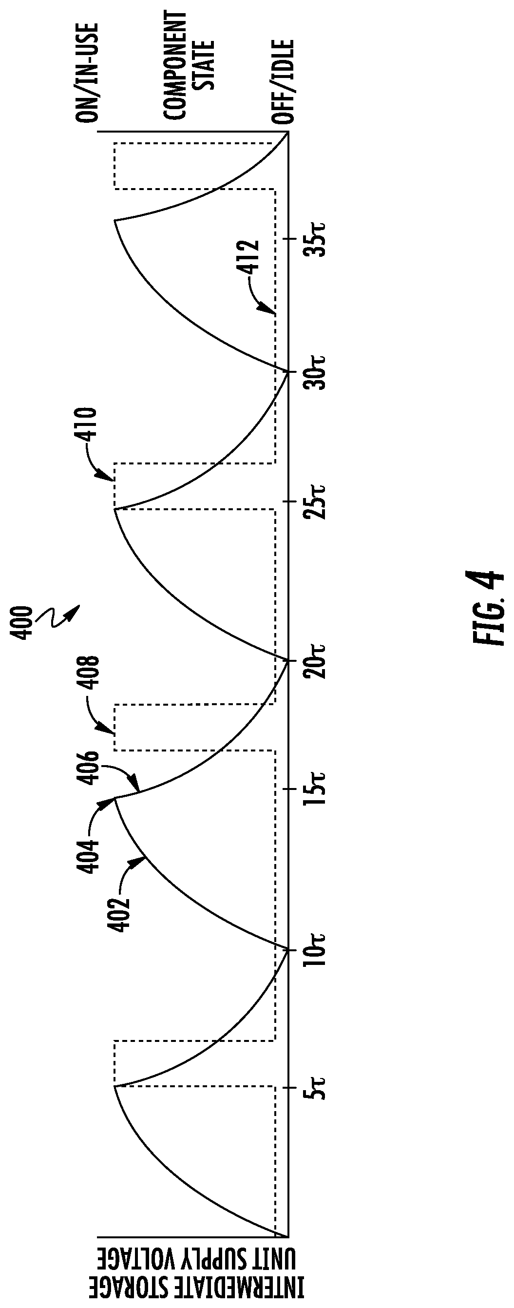
FIG. 4 graphically depicts an exemplary sequence of providing electric power to an electric component in a device.
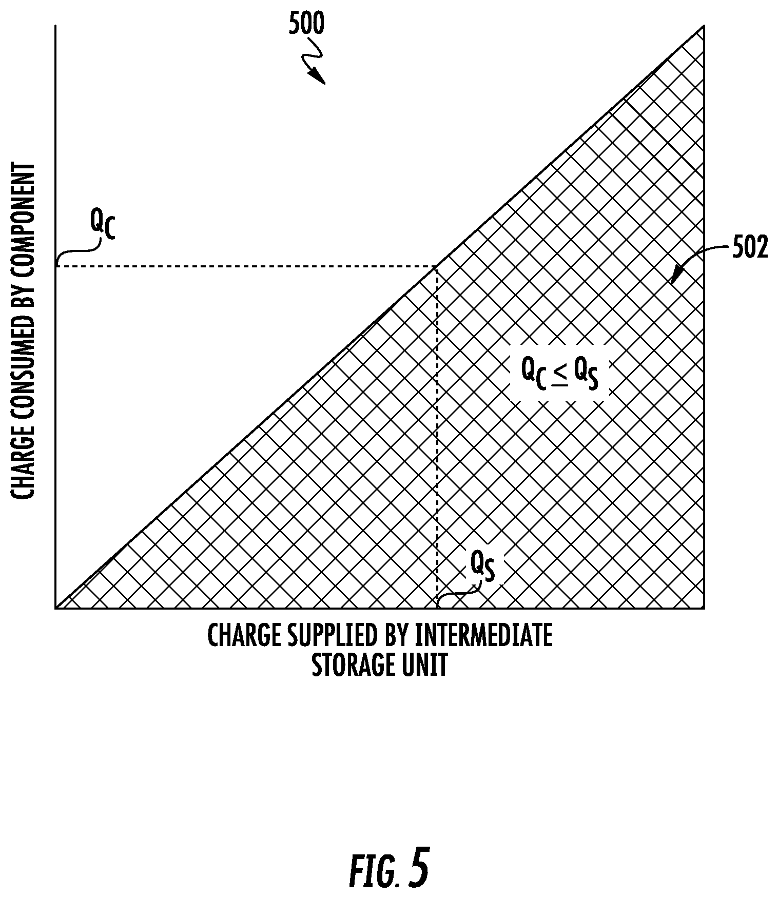
FIG. 5 graphically depicts an exemplary relationship between a charge consumed by a component and a charge supplied by an intermediate storage unit.
FIG. 6A shows an exemplary method of performing a task using power supplied by an intermediate storage unit.
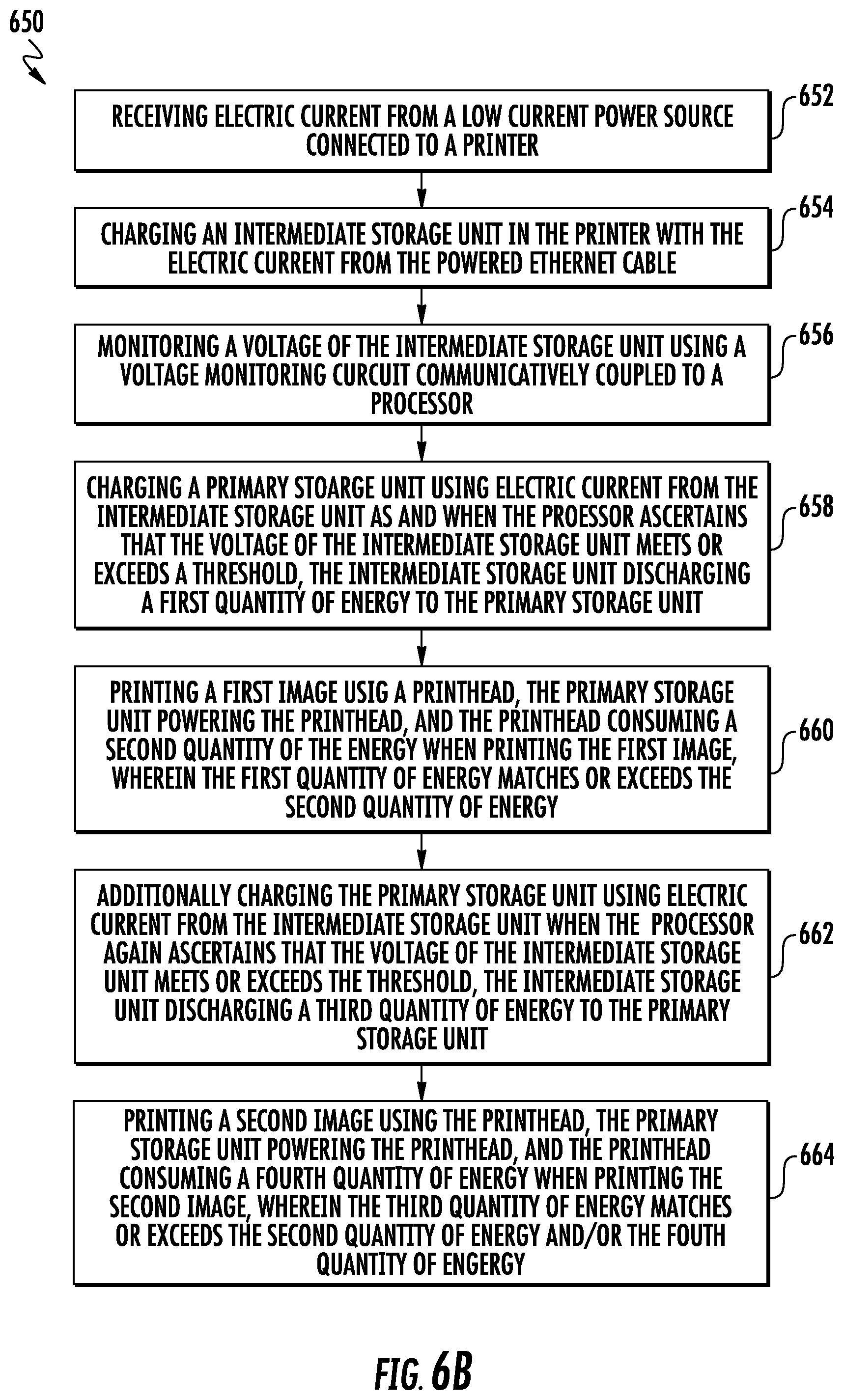
FIG. 6B shows an exemplary method of printing on a print medium using power supplied by an intermediate storage unit.
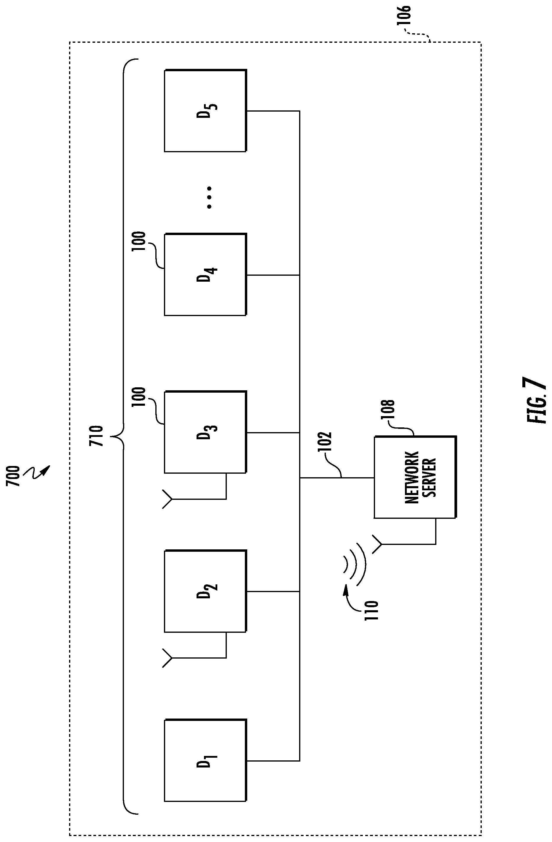
FIG. 7 shows an exemplary distributed computing system.
FIG. 8 shows an exemplary method of preferentially assigning tasks to devices in a distributed computing system.
DETAILED DESCRIPTION
In the following detailed description, various aspects and features are described in greater detail with reference to the accompanying figures, including among other aspects and features, exemplary devices, systems, and methods that use a low current power source to perform various device functions, including devices, systems, and methods that use a lower current power source to charge an intermediate storage unit, providing sufficient electric power to perform various device functions. Numerous specific details are set forth in order to provide a thorough understanding of the present disclosure. It will be apparent, however, to one skilled in the art that the presently disclosed devices, systems, and methods may be provided without some or all of these specific details. In other instances, well known aspects have not been described in detail in order not to unnecessarily obscure the present disclosure. The following detailed description is therefore not to be taken in a limiting sense, and it is intended that other embodiments are within the spirit and scope of the present disclosure.
Electrical energy can be "harvested" from any low current power source. Exemplary low current power sources include a powered Ethernet cable, a powered Universal Serial Bus, and/or magnetic fields or electric fields associated with Wi-Fi and other wireless communication or broadcast signals. In some embodiments, the low current power source may be an electric field or magnetic field associated with FM or AM radio waves. In some embodiments, the low current power source may be light energy harvested using one or more solar cells. The solar cells may be configured to harvest light energy present in the environment, including direct or indirect sunlight, ambient light, room lights, and combinations thereof.
FIG. 1 shows a device 100 configured to harvest electrical energy from a low current power source. In various embodiments, the device 100 may be a workflow solutions tool deployed in a distributed computing system. The device may be a printer (such as a thermal transfer printer), a mobile device (such as a mobile phone or a tablet), a barcode scanner, a dimensioner, or any other device. The device may perform several functions in a distributed computing system, such as scanning and printing.
Exemplary distributed computing systems include those typically deployed in healthcare facilities or supply chain environments. For example, a healthcare facility such as a hospital may have a distributed computing system with printers, scanners, and other devices 100 stationed throughout the facility. Such might be used by healthcare personnel to print and scan image associated with patient identification and management of care or other healthcare related tasks. Such devices 100 may include a medical device used by healthcare personnel to perform a medical treatment, procedure, or various other care. Similarly, printers, scanners, and other devices 100 may be stationed in various locations throughout a supply chain environment for use by personnel who manage or work in the supply chain or who perform various related task. Such devices 100 may include an inventory management tool used by supply chain personnel to identify or track items moving through the supply chain.
As shown in FIG. 1, the low current power source may include a powered Ethernet cable (i.e., PoE) 102. The powered Ethernet cable may supply an ethernet connection to the device 100. The ethernet connection may be supplied using an ethernet connection device 104. The Ethernet connection device 104 may allow communications across a network 106, such as between the device 100 a network resource 108 such as a server. In addition, or in the alternative, the device 100 may be configured to allow wireless communications across the network 106 using a wireless communication signal 110. The device may be configured to harvest electricity from a low current power source, such as from the powered Ethernet cable 102, from an electric or magnetic field associated with the wireless communications signal 110, or from any other suitable low current power source or combination of low current power sources.
The device 100 includes an Ethernet interface 112, which separates the data and power components from the powered Ethernet cable 102. The data component is communicated to circuity in a processor 114 for operating the device. The power component flows to a power converter 116. The power converter is configured to convert the power component from a supply voltage to a requisite storage voltage. For example, a typical powered Ethernet cable supplies 48 volts of AC power, though other supply voltages are also possible. The power converter may be configured to convert the supply voltage to any desired storage voltage. For example, a typical device 100 may be configured to utilize 20-24 volts of DC power.
In some embodiments, the device 100 may include an antenna 118 configured to receive wireless communication or broadcast signals 110. Electric or magnetic fields associated with the signals may be converted to a desired storage voltage using an appropriately configured power converter 116.
In some embodiments, the device 100 may include one or more solar cells 120 configured to harvest light energy present in the environment 122. The light energy harvested by the solar cells may include direct or indirect sunlight, ambient light, room lights, and combinations thereof. Light energy harvested by the solar cells may be converted to a desired storage voltage using an appropriately configured power converter 116.
Electric current from the power converter 116 is supplied to an intermediate storage unit 124. The intermediate storage unit may be a capacitor or a supercapacitor, or an arrangement of several capacitors or supercapacitors (e.g., intermediate storage units I.sub.1 through I.sub.n). The capacitors or supercapacitors making up the intermediate storage unit may be arranged in parallel or series, or combinations thereof. A diode (e.g., D1) 126 or similar circuitry may be provided to permit the flow of electric current from the power converter to the intermediate storage unit.
The intermediate storage unit periodically discharges electric current to a primary storage unit 128. The primary storage unit may be a rechargeable battery or a supercapacitor, or an arrangement of multiple rechargeable batteries or supercapacitors (e.g., primary storage units P.sub.1 through P.sub.n). The rechargeable batteries or supercapacitors making up the primary storage unit may be arranged in parallel or series, or combinations thereof. A diode (e.g., D2) 130 or similar circuitry may be provided to permit the flow of electric current from the intermediate storage unit to the primary storage unit.
In some embodiments, a voltage monitoring circuit 132 may be provided. The voltage monitoring circuit may be configured to enable the processor 114 to monitor the voltage across the intermediate storage unit. The processor may be further configured to control the charging and discharging of the intermediate storage unit, for example, using control circuitry associated with the diode 130.
The device 100 includes one or more components (e.g., components C.sub.1 through C.sub.n) 134 configured to receive power from the primary storage unit. The components 134 may include a subset of the powered components in the device. For example, the components 134 may receive power from the primary storage unit, and other powered components in the device may receive power from a different source such as a different battery or the like. In some embodiments, the charge accumulated by the intermediate storage unit may be insufficient to power every electric component in the device, but may be sufficient to power a subset of the components 134 (e.g., components C.sub.1 through C.sub.n. The primary storage unit may be configured to supply power only to a subset of components. Such a subset of components may be selected based on the expected rate of energy harvesting. In some embodiments, the energy supplied by the intermediate storage unit may be sufficient to supply enough power to operate the components 134 under typical operating conditions. Under peak operating conditions (e.g., unusually frequent use, high demand situations, etc.) the components 134 may require additional power, even if the intermediate storage unit may be sufficient under typical operating conditions.
An intermediate storage unit such as a capacitor or supercapacitor can be modeled as a resistor-capacitor circuit (RC circuit). As an intermediate storage unit stores charge, the voltage V across the intermediate storage unit is proportional to the charge q stored, given by the relationship V=q/C (1), where C is the capacitance. When charge flows out of the intermediate storage unit, the voltage is proportional to the current, given by the relationship V=RdQ/dt (2), where R is the resistance. The equality RdQ/dt=Q/C (3) has an exponential solution. Accordingly, the charge of an intermediate storage unit is given by the relationship: Q=CV.sub.s(1-e.sup.-t/RC) (4), where V.sub.s is the supply voltage to the intermediate storage unit, and t is the time elapsed since the application of the supply voltage. The term RC is a time constant, .tau. (tau), where R has units of Ohms and C has units in Farads.
As the voltage across the intermediate storage unit is proportional to its charge, the voltage displays similar exponential behavior. Accordingly, the voltage across the intermediate storage unit is given by the relationship: V=V.sub.s(1-e.sup.-t/RC) (5), where V.sub.s is the supply voltage to the intermediate storage unit, and t is the time elapsed since the application of the supply voltage.
FIG. 2A graphically depicts an exemplary charging curve 200 for an intermediate storage unit. When charging an intermediate storage unit, the charging current 202 is found by Ohm's Law as: I=V.sub.s/R. The charging rate is initially high and then decreases exponentially, asymptotically approaching zero. Likewise, the charge on the intermediate storage unit 204 initially increases rapidly and then rate of increasing charge declines exponentially as the potential difference across the intermediate storage unit asymptotically approaching a maximum charge or supply voltage.
The time constant .tau. (tau) represents the time it takes for the voltage across the intermediate storage unit to either rise or fall to within 1/e of its final value. When charging the intermediate storage unit .tau. (tau) represents the time it takes to reach V.sub.s(1-1/e). When discharging the intermediate storage unit, .tau. (tau) is the time it takes to reach V.sub.s(1/e). The rate of change is a fractional, 1-1/e per .tau. (tau). As such, when charging the intermediate storage unit for a time period t=.tau. (tau), the supply voltage or charge on the capacitor will increase by about 63.2% (i.e., 1-1/e) from t=N.tau. to t=(N+1).tau.. Accordingly, the intermediate storage unit typically will be charged about 63.2% of maximum (Q.sub.MAX) after .tau. (tau), and typically will be essentially fully charged (i.e., 99.3%) after 5.tau.. Likewise, the charging current typically will decrease by about 36.8% of maximum (I.sub.MAX) after .tau. (tau), and typically will be essentially zero (i.e., 0.7%) after 5.tau..
FIG. 2B graphically depicts an exemplary discharge curve 210 for an intermediate storage unit. When the intermediate storage is discharged, the discharge current 212 is initially high and then decreases exponentially with time, asymptotically approaching zero. Likewise, the charge on the intermediate storage unit 214 initially decreases rapidly and then the rate of decreasing charge declines exponentially as the potential difference across the intermediate storage unit asymptotically approaches zero. The intermediate storage unit typically will be discharged about 63.2% of maximum (Q.sub.MAX) after .tau. (tau), and typically will be essentially fully discharged (i.e., 99.3%) after 5.tau.. Likewise, the discharging current typically will decrease by about 36.8% of maximum (I.sub.MAX) after .tau. (tau), and typically will be essentially zero (i.e., 0.7%) after 5.tau..
A voltage monitoring circuit 132 may be configured to allow a processor 114 to control the charging and discharging of the intermediate storage unit. The processor may provide electric power harvested from a low current power source 102, 110, to an electric component in a device 134 based at least in part on the control of such charging and discharging. The electric power may be provided to the electric component either directly or through a primary storage unit 128.
FIG. 3 shows an exemplary method 300 of providing electric power to an electric component in a device. The method begins with receiving electric current from a low current power source connected to a device 310. The low current power source may be a powered Ethernet cable 102, an electric or magnetic field associated with a wireless signal 110, or any other suitable low current power source or combination of low current power sources. The method continues with charging an intermediate storage unit 124 in the device with the electric current 320, and monitoring a voltage of the intermediate storage 330 unit using a voltage monitoring circuit 132 communicatively coupled to a processor 114.
The method continues with charging a primary storage unit using electric current from the intermediate storage unit 340. In an exemplary embodiment, the processor and the voltage monitoring circuit may be configured to cause the intermediate storage unit to discharge electric current to the primary storage unit when the processor ascertains that the voltage of the intermediate storage unit meets or exceeds a threshold. The primary storage unit accordingly discharges electric current to one or more components 350. The electric current may be used by the one or more components 134 to cause the device to perform a function.
In some embodiments the method 300 may be performed using a printer, such as a thermal printer. The electric current from the primary storage unit may be used to cause a printing mechanism (e.g., a printhead) to print an image. The electric current may also be used by other components 134. In some embodiments, these components 134 may be configured to receive electric power solely form the primary storage unit.
The threshold for discharging electric current to the primary storage unit may include or depend on a voltage range of the intermediate storage unit. For example, a threshold may correspond to a voltage range falling between a lower voltage sufficient for efficiently discharging current to the primary storage unit and an upper voltage sufficient for further charging of the intermediate storage to be inefficient. The lower voltage and the upper voltage may be selected based on charging curves 200 and discharging curves 210 for the intermediate storage unit. In some embodiments, the threshold may be triggered when the processor ascertains that the voltage monitoring circuit has detected a voltage corresponding to a charge on the intermediate storage unit sufficient to provide a discharging current at least exceeding a defined value. The defined value may be a discharging current of the intermediate storage unit.
In some embodiments the threshold may include or depend on a time constant .tau. (tau) derived from a resistance R of charging the intermediate storage unit multiplied by a capacitance C of the intermediate storage unit. Alternatively, the threshold may include or depend on a voltage or charge on the intermediate storage unit corresponding to the time constant .tau. (tau). The threshold may be a range or an absolute value. For example, the threshold may include or correspond to a voltage across the intermediate storage unit (or a charge on the intermediate storage unit) corresponding to a positive multiple of the time constant .tau. (tau) for the intermediate storage unit.
The threshold may additionally or alternatively include or depend on one or more parameters associated with a charging curve corresponding to a primary storage unit. A primary storage unit may exhibit a charging curve given by the relationship shown in equation (5) above, similar to the charging curve shown in FIG. 2A. Typically, the supply voltage to the primary storage unit corresponds to the discharge voltage of the intermediate storage unit. The time constant, .tau. (tau), may differ as between charging the intermediate storage unit and discharging to the primary storage unit because of a differing resistance R or capacitance C.
Additionally, the charging current to the primary storage unit (i.e., the discharging current of the intermediate storage unit) may vary depending on the charge on the primary storage unit. When the charge on the intermediate storage unit is high, initially the discharging current to the primary storage unit will also be high. However, a high charge on the primary storage unit may add resistance to the discharge of current from the intermediate storage unit. Accordingly, in some embodiments, the threshold may depend on a relationship between the charge on the intermediate storage unit and a charge on the primary storage unit.
For example, the threshold may include or depend on the charging current of the primary storage unit (or the discharging current of the intermediate storage unit) exceeding the charging current of the intermediate storage unit. Such a threshold may dynamically vary with differing values for the respective charging currents. For example, the threshold may include or depend on an efficiency of discharging current to the primary storage unit exceeding an efficiency of further charging of the intermediate storage. An efficiency factor E.sub.i-p may be characterized as a ratio of the charging current of the primary storage unit over the charging current of the intermediate storage unit. The threshold may include or depend on the efficiency factor E being greater than a defined value. The defined value may be 1.0, such that the threshold will be triggered when the charging current of the primary storage unit exceeds the charging current of the intermediate storage unit.
Alternatively, the defined value may be greater than 1.0, such that the threshold will be triggered when the charging current of the primary storage unit sufficiently exceeds the charging current of the intermediate storage unit by some defined amount.
In some embodiments, the charge on the primary storage unit may be configured to discharge directly to one or more components 134. The primary storage unit may be configured to discharge to the primary storage unit under some conditions, and to discharge directly to the one or more components under other conditions. For example, the primary storage unit may be configured to discharge to the one or more components when the efficiency of discharging current to the one or more components exceeds an efficiency of further charging of the intermediate storage and/or discharging current to the primary storage unit.
In some embodiments, the energy harvested from a low current power source may be sufficient to supply power to the one or more components 134. In various settings, the one or more components may typically receive intermittent use at time intervals large enough for the intermediate storage unit to accumulate a charge sufficient to power the components during such intermittent use. Such intermittent use may arise in the context of a distributed computing system where a device 100 or various components 134 of the device typically receive intermittent use. A distributed computing system for a healthcare facility or a supply chain may have printers, scanners, and other devices 100 deployed in various locations that typically receive intermittent use. For example, printers and scanners 100 in a healthcare facility may be used intermittently by healthcare personnel to print and scan images associated with patient identification and management of care. Additionally, medical devices 100 may be used intermittently by healthcare personnel to perform a medical treatment, procedure, or various other care or related tasks. Similarly, printers, scanners, inventory management tools, and other devices 100 stationed in various locations throughout a supply chain environment may be used intermittently for used by personnel who manage or work the supply chain or who perform various related task.
In some embodiments, a positive multiple of a time constant .tau. (tau) for the intermediate storage unit may exceed the typical interval between such intermittent use. A device may be provided with an intermediate storage unit configured to accumulate a voltage over the positive multiple of the time constant which voltage exceeds the charge consumed by a typical instance of use of the component. Over a time period reflective of the typical interval between intermittent use, the intermediate storage unit may discharge enough energy to supply electric power to the device 100 or to the components 134. As such, the energy harvested from the low current power source may be sufficient to supply power to the device 100 or to components 134 of the device given such intermittent use under typical operating conditions. In some embodiments, however, the energy harvested from the low current power source may be inadequate to meet the power consumption of the device 100 or of the components 134 of the device under peak operating conditions (e.g., unusually frequent use, high demand situations, etc.) even though the low current power source may be adequate under typical operating conditions.
By way of example, FIG. 4 graphically depicts an example sequence 400 of providing electric power to a component 134 in a device 100. The intermediate storage unit accumulates a charge 402. When the charge on the intermediate storage unit meets a threshold 404, the current may be discharged 406 to the primary storage unit or directly to the components 134. The threshold may include or depend on a positive multiple of a time constant, .tau. (tau) for the intermediate storage unit. As shown, the threshold is 5.tau.; however, other suitable thresholds are within the spirit and scope of the present disclosure. Meanwhile, the device 100 or the components 134 receive intermittent use 408. Such use may alternate between On/Off or In-Use/Idle 410, 412, as applicable. The time interval of the intermittent use shown in FIG. 4 matches or exceeds the threshold. A given intermittent use of the device 100 or the components 134 may consume up to all of the electrical energy harvested from the low current power source. Thus, the low current power source may be sufficient to power the device or the components when the time interval of the intermittent use exceeding the threshold.
In some embodiments, the intermediate storage unit may need to progress through several charging and discharging cycles before enough energy will have been accumulated in the primary storage unit to meet the power consumption of the device 100 or components 134. For example, the requisite time interval may exceed 5.tau., 10.tau., 15.tau., or more, reflecting multiple cycles of charging the intermediate storage unit and discharging to the primary storage unit.
FIG. 5 graphically depicts an example relationship 500 between a charge consumed by one or more components 134 and a charge supplied by an intermediate storage unit. The shaded region 502 indicates the condition where the charge consumed by the one or more components is less than or equal to the charge supplied by the intermediate power source over a given time interval. As the time interval between intermittent uses increases, the charge supplied by the intermediate storage unit increases. Accordingly, the time interval may be selected so that the charge supplied by the intermediate power source meets or exceeds the charge consumed by the one or more components.
In some embodiments, a device 100 may be configured to use energy from an intermediate storage unit to power one or more components 134 only when the charge consumed by the one or more components is less than or equal to the charge supplied by the intermediate power source, such as indicated by the relationship shown in FIG. 5. Instead, the device or the one or more components may utilize an alternative power source when the charge consumed by the one or more components exceeds the charge supplied by the intermediate power source. For example, the alternative power source may be a battery or a supercapacitor. The device or the one or more components may utilize such alternative power source, for example, when the time interval between instances of intermittent is less than the time required to accumulate enough energy from the intermediate storage unit to power the device or the one or more components. In some embodiments, a device 100 or components thereof 134 may typically receive intermittent use at time intervals matching or exceeding a positive multiple of a time constant .tau. (tau) for the intermediate storage unit. The intermediate storage unit may be configured to accumulate a voltage over the positive multiple of the time constant, which voltage exceeds the charge consumed by a typical instance of intermittent use of the device 100 or the components 134.
FIG. 6A shows an exemplary method 600 of performing a task using power supplied by an intermediate storage unit. The method 600 may be applied for any device or device function within the spirit and scope of the present disclosure. An exemplary method 600 begins with a device 100 receiving electric current from a low current power source (e.g., a powered Ethernet cable, a radio frequency field, or other low current power source) connected to the device 610, and charging an intermediate storage unit 124 in the device with the electric current from the low current power source 620. A processor 114 may be configured to monitor a voltage of the intermediate storage unit 630 using a voltage monitoring circuit 132 communicatively coupled to the processor.
The method continues with charging a primary storage unit 128 using electric current from the intermediate storage unit when the processor ascertains that the voltage of the intermediate storage unit meets or exceeds a threshold 640. A suitable threshold may be selected in accordance with the present disclosure. For example, a threshold may include or depend on a voltage of the intermediate storage unit corresponding to a positive multiple of a time constant .tau. (tau) for the intermediate storage unit.
Accordingly, the intermediate storage unit discharges a first quantity of energy to the primary storage unit. The first quantity of energy may correspond to one or more charging and discharging sequences each meeting or exceeding a time interval corresponding to a positive multiple of the time constant, .tau. (tau). In some embodiments, the time interval may exceed 5.tau., 10.tau., 15.tau., or more, reflecting multiple discharges from the intermediate storage unit to the primary storage unit.
The method 600 continues with performing a first task using a component 650, with the primary storage unit powering the component. The first task may be performed after a first time interval matching or exceeding a positive multiple of the time constant. The component consumes a second quantity of energy when performing the first task, and the first quantity of energy matches or exceeds the second quantity of energy. The second quality of energy may include or equate to a quantity of energy consumed by the component when performing the first task. In some embodiments, the method 600 continues with the primary storage unit undergoing additional charging using electric current from the intermediate storage unit when the processor again ascertains that the voltage of the intermediate storage unit meets or exceeds the threshold 660. The intermediate storage unit accordingly discharges a third quantity of energy to the primary storage unit.
The method continues with performing a second task using the component 670, with the primary storage unit powering the component. The component consumes a fourth quantity of energy when performing the second task, and the third quantity of energy matches or exceeds the second quantity of energy and/or the fourth quantity of energy. In addition, or in the alternative, the method 600 continues with discharging a third quantity of energy from the intermediate storage unit to the primary storage unit, and then performing a second task using the component, with the third quantity of energy matching or exceeding the second quantity of energy. The second task may be performed after a second time interval commencing after the first time interval. The second time interval may match or exceed a positive multiple of the time constant.
The method shown in 6A may be performed using any device configured to harvest energy from a low current power source. For example, in some embodiments, the device may be a printer and the task may be printing an image on a print medium. FIG. 6B shows an exemplary method 650 of printing an image on a print medium using power supplied by an intermediate storage unit. The method 600 may be similarly applied for other devices or device functions, which are within the spirit and scope of the present disclosure. An exemplary method 650 begins with a printer (or other device) 100 receiving electric current from a low current power source (e.g., a powered Ethernet cable, a radio frequency field, or other low current power source) connected to the printer 652, and charging an intermediate storage unit 124 in the printer with the electric current from the low current power source 654. A processor 114 may be configured to monitor a voltage of the intermediate storage unit 656 using a voltage monitoring circuit 132 communicatively coupled to the processor.
The method continues with charging a primary storage unit 128 using electric current from the intermediate storage unit when the processor ascertains that the voltage of the intermediate storage unit meets or exceeds a threshold 658. A suitable threshold may be selected in accordance with the present disclosure. For example, a threshold may include or depend on a voltage of the intermediate storage unit corresponding to a positive multiple of a time constant .tau. (tau) for the intermediate storage unit.
Accordingly, the intermediate storage unit discharges a first quantity of energy to the primary storage unit. The first quantity of energy may correspond to one or more charging and discharging sequences each meeting or exceeding a time interval corresponding to a positive multiple of the time constant .tau. (tau). In some embodiments, the time interval may exceed 5.tau., 10.tau., 15.tau., or more, reflecting multiple discharges from the intermediate storage unit to the primary storage unit.
The method 650 continues with printing a first image using a printing mechanism (e.g., including a printhead or other component) 660, with the primary storage unit powering the printing mechanism. The first image may be printed after a first time interval matching or exceeding a positive multiple of the time constant. In some embodiments, the printing mechanism printhead consumes a second quantity of energy when printing the first image, and the first quantity of energy matches or exceeds the second quantity of energy. In some embodiments, the printing mechanism includes a printhead. In some embodiments, the printer may be a thermal printer and the printing mechanism includes a thermal printhead. In some embodiments, the second quality of energy may include or equate to a quantity of energy consumed by the thermal printhead when printing the first image.
In some embodiments, the method 650 continues with the primary storage unit undergoing additional charging using electric current from the intermediate storage unit as and when the processor again ascertains that the voltage of the intermediate storage unit meets or exceeds the threshold 662. The intermediate storage unit accordingly discharges a third quantity of energy to the primary storage unit. The method continues with printing a second image using the printing mechanism (e.g., including a printhead) 664, with the primary storage unit powering the printing mechanism. The printing mechanism consumes a fourth quantity of energy when printing the second image, and the third quantity of energy matches or exceeds the second quantity of energy and/or the fourth quantity of energy. In addition, or in the alternative, the method 650 continues with discharging a third quantity of energy from the intermediate storage unit to the primary storage unit, and then printing a second image using the printing mechanism, with the third quantity of energy matching or exceeding the second quantity of energy. The second image may be printed after a second time interval commencing after the first time interval. The second time interval may match or exceed a positive multiple of the time constant.
The devices and methods of the present disclosure may be utilized or implemented in a distributed computing system. For example, FIG. 7 shows an exemplary distributed computing system 700. The distributed computing system includes a plurality of devices 710, which may include one or more devices configured in accordance with the device 100 shown in FIG. 1. The distributed computing system may be part of a network 106 and may include one or more network resources 108 such as a network server.
The distributed computing system may be deployed in the context of a healthcare facility and/or a supply chain environment. The devices 710 may include printers, scanners, medical devices, and inventory management tools. Other devices 710 are also within the spirit and scope of the present disclosure, including other devices used by healthcare personnel to perform a medical treatment, procedure, or various other care, and other devices used by personnel who manage or work in the supply chain or who perform various supply-chain related tasks.
The devices 710 are configured to communicate with the network resource 108 either using a powered Ethernet cable 102 and/or a wireless communication signal 110. The devices are configured to harvest electricity from one or more low current power sources. The low current power source may include a powered Ethernet cable 102, an electric or magnetic field associated with the wireless communications signal 110, or any other suitable low current power source or combination of low current power sources. The network resource may be configured to assign tasks to the plurality of devices. Some of the tasks may be preferentially assigned to a device 100 selected from among the plurality 710. Tasks may be preferentially assigned to a device based one or more criteria associated with the energy harvested from the low current power source. The criteria may include or depend on a time interval, a threshold, or an efficiency factor including those described in the present disclosure. Other distributed computing systems and configurations thereof, and criteria for assigning tasks to devices, will be apparent and are within the spirit and scope of the present disclosure.
FIG. 8 shows an exemplary method 800 of preferentially assigning tasks to devices 710 in a distributed computing system. The method begins upon monitoring with a network resource 108, a plurality of devices on a network 810. Each of the plurality of devices has a network connection providing communication with the network resource. The network connection may be supplied, for example, by a powered ethernet cable 102 and/or a wireless communications signal 110. Each of the devices further has an intermediate storage unit 124 configured to harvest electricity from a low current power source. The low current power source may be attributed to the network connection, such as the powered ethernet cable or an electric or magnetic field associated with the wireless communications signal. In some embodiments, the low current power source may be FM or AM radio waves.
The method continues with the network resource receiving a signal indicating a task to be performed 820. The network resource preferentially assigns the task to a device selected from among the plurality of the devices based at least in part on a parameter or threshold 830. The parameter or threshold may be associated with the intermediate storage unit and/or power consumption by the device or one or more components thereof.
In some embodiments, the distributed computing system 700 may include a computer network 106 in which a plurality of devices 710 each have a network connection supplied by a low current power source, such as a powered Ethernet cable 102 or a wireless communications signal 110, that allows the devices to communicate with at least one network resource 108.
Each of the plurality of devices 710 may include an intermediate storage unit 124 configured to receive electric current from the low current power source, a primary storage unit 128 configured to receive electric current discharged from the intermediate storage unit, and one or more components 134 configured to use electric current from the primary storage unit to perform a function. As described herein, the electric current form the low current power source at least partially charges the intermediate storage unit. The devices 710 may further include a voltage monitor circuit 132 communicatively coupled to a processor 114 configured to monitor a voltage of the intermediate storage unit. The processor may be configured to discharge current from the intermediate storage when the processor ascertains that the voltage of the intermediate storage unit meets or exceeds a threshold. The electric current from the intermediate storage unit at least partially charges the primary storage unit. As described herein, the primary storage unit also may be configured to provide the electric current directly to the one or more components.
At least some of the devices 100 from among the plurality 710, or one or more components thereof 134, may typically receive intermittent use at time intervals matching or exceeding a positive multiple of a time constant .tau. (tau) for the respective intermediate storage unit 124. The respective intermediate storage units may be configured to accumulate a voltage over the positive multiple of the time constant, and the voltage may exceed the charge consumed by a typical instance of use of the respective device or one or more components.
The network resource may include at least one server 108 configured to assign tasks to the plurality of devices. Tasks may be preferentially assigned from time to time to a device selected from among the plurality, or to a component of such a device. The preferential assignment may be based on a time interval having elapsed since the selected device (or component) last performed a task. The time interval may match or exceed a positive multiple of the time constant .tau. (tau). In addition, or in the alternative, the preferential assignment also may be based on the respective intermediate storage unit having accumulated a voltage corresponding to a threshold. A suitable threshold may be selected in accordance with the present disclosure. For example, a threshold may include or depend on a voltage of the intermediate storage unit corresponding to a positive multiple of a time constant .tau. (tau) for the intermediate storage unit.
In some embodiments, the network resource may be configured to preferentially assign a next task to a device selected from among the plurality based on the selected device having discharged a first quantity of energy from the intermediate storage unit to the primary storage unit since the selected device last performed a previous task. The first quantity of energy may match or exceed a second quantity of energy attributed to the next task. For example, the second quantity of energy may include or depend on a quantity of energy necessary or sufficient for performing the next task.
To supplement the present disclosure, this application incorporates entirely by reference the following commonly assigned patents, patent application publications, and patent applications: U.S. Pat. Nos. 6,832,725; 7,128,266; U.S. Pat. Nos. 7,159,783; 7,413,127; U.S. Pat. Nos. 7,726,575; 8,294,969; U.S. Pat. Nos. 8,317,105; 8,322,622; U.S. Pat. Nos. 8,366,005; 8,371,507; U.S. Pat. Nos. 8,376,233; 8,381,979; U.S. Pat. Nos. 8,390,909; 8,408,464; U.S. Pat. Nos. 8,408,468; 8,408,469; U.S. Pat. Nos. 8,424,768; 8,448,863; U.S. Pat. Nos. 8,457,013; 8,459,557; U.S. Pat. Nos. 8,469,272; 8,474,712; U.S. Pat. Nos. 8,479,992; 8,490,877; U.S. Pat. Nos. 8,517,271; 8,523,076; U.S. Pat. Nos. 8,528,818; 8,544,737; U.S. Pat. Nos. 8,548,242; 8,548,420; U.S. Pat. Nos. 8,550,335; 8,550,354; U.S. Pat. Nos. 8,550,357; 8,556,174; U.S. Pat. Nos. 8,556,176; 8,556,177; U.S. Pat. Nos. 8,559,767; 8,599,957; U.S. Pat. Nos. 8,561,895; 8,561,903; U.S. Pat. Nos. 8,561,905; 8,565,107; U.S. Pat. Nos. 8,571,307; 8,579,200; U.S. Pat. Nos. 8,583,924; 8,584,945; U.S. Pat. Nos. 8,587,595; 8,587,697; U.S. Pat. Nos. 8,588,869; 8,590,789; U.S. Pat. Nos. 8,596,539; 8,596,542; U.S. Pat. Nos. 8,596,543; 8,599,271; U.S. Pat. Nos. 8,599,957; 8,600,158; U.S. Pat. Nos. 8,600,167; 8,602,309; U.S. Pat. Nos. 8,608,053; 8,608,071; U.S. Pat. Nos. 8,611,309; 8,615,487; U.S. Pat. Nos. 8,616,454; 8,621,123; U.S. Pat. Nos. 8,622,303; 8,628,013; U.S. Pat. Nos. 8,628,015; 8,628,016; U.S. Pat. Nos. 8,629,926; 8,630,491; U.S. Pat. Nos. 8,635,309; 8,636,200; U.S. Pat. Nos. 8,636,212; 8,636,215; U.S. Pat. Nos. 8,636,224; 8,638,806; U.S. Pat. Nos. 8,640,958; 8,640,960; U.S. Pat. Nos. 8,643,717; 8,646,692; U.S. Pat. Nos. 8,646,694; 8,657,200; U.S. Pat. Nos. 8,659,397; 8,668,149; U.S. Pat. Nos. 8,678,285; 8,678,286; U.S. Pat. Nos. 8,682,077; 8,687,282; U.S. Pat. Nos. 8,692,927; 8,695,880; U.S. Pat. Nos. 8,698,949; 8,717,494; U.S. Pat. Nos. 8,717,494; 8,720,783; U.S. Pat. Nos. 8,723,804; 8,723,904; U.S. Pat. Nos. 8,727,223; 8,740,082; U.S. Pat. Nos. 8,740,085; 8,746,563; U.S. Pat. Nos. 8,750,445; 8,752,766; U.S. Pat. Nos. 8,756,059; 8,757,495; U.S. Pat. Nos. 8,760,563; 8,763,909; U.S. Pat. Nos. 8,777,108; 8,777,109; U.S. Pat. Nos. 8,779,898; 8,781,520; U.S. Pat. Nos. 8,783,573; 8,789,757; U.S. Pat. Nos. 8,789,758; 8,789,759; U.S. Pat. Nos. 8,794,520; 8,794,522; U.S. Pat. Nos. 8,794,525; 8,794,526; U.S. Pat. Nos. 8,798,367; 8,807,431; U.S. Pat. Nos. 8,807,432; 8,820,630; U.S. Pat. Nos. 8,822,848; 8,824,692; U.S. Pat. Nos. 8,824,696; 8,842,849; U.S. Pat. Nos. 8,844,822; 8,844,823; U.S. Pat. Nos. 8,849,019; 8,851,383; U.S. Pat. Nos. 8,854,633; 8,866,963; U.S. Pat. Nos. 8,868,421; 8,868,519; U.S. Pat. Nos. 8,868,802; 8,868,803; U.S. Pat. Nos. 8,870,074; 8,879,639; U.S. Pat. Nos. 8,880,426; 8,881,983; U.S. Pat. Nos. 8,881,987; 8,903,172; U.S. Pat. Nos. 8,908,995; 8,910,870; U.S. Pat. Nos. 8,910,875; 8,914,290; U.S. Pat. Nos. 8,914,788; 8,915,439; U.S. Pat. Nos. 8,915,444; 8,916,789; U.S. Pat. Nos. 8,918,250; 8,918,564; U.S. Pat. Nos. 8,925,818; 8,939,374; U.S. Pat. Nos. 8,942,480; 8,944,313; U.S. Pat. Nos. 8,944,327; 8,944,332; U.S. Pat. Nos. 8,950,678; 8,967,468; U.S. Pat. Nos. 8,971,346; 8,976,030; U.S. Pat. Nos. 8,976,368; 8,978,981; U.S. Pat. Nos. 8,978,983; 8,978,984; U.S. Pat. Nos. 8,985,456; 8,985,457; U.S. Pat. Nos. 8,985,459; 8,985,461; U.S. Pat. Nos. 8,988,578; 8,988,590; U.S. Pat. Nos. 8,991,704; 8,996,194; U.S. Pat. Nos. 8,996,384; 9,002,641; U.S. Pat. Nos. 9,007,368; 9,010,641; U.S. Pat. Nos. 9,015,513; 9,016,576; U.S. Pat. Nos. 9,022,288; 9,030,964; U.S. Pat. Nos. 9,033,240; 9,033,242; U.S. Pat. Nos. 9,036,054; 9,037,344; U.S. Pat. Nos. 9,038,911; 9,038,915; U.S. Pat. Nos. 9,047,098; 9,047,359; U.S. Pat. Nos. 9,047,420; 9,047,525; U.S. Pat. Nos. 9,047,531; 9,053,055; U.S. Pat. Nos. 9,053,378; 9,053,380; U.S. Pat. Nos. 9,058,526; 9,064,165; U.S. Pat. Nos. 9,064,165; 9,064,167; U.S. Pat. Nos. 9,064,168; 9,064,254; U.S. Pat. Nos. 9,066,032; 9,070,032; U.S. Pat. Nos. 9,076,459; 9,079,423; U.S. Pat. Nos. 9,080,856; 9,082,023; U.S. Pat. Nos. 9,082,031; 9,084,032; U.S. Pat. Nos. 9,087,250; 9,092,681; U.S. Pat. Nos. 9,092,682; 9,092,683; U.S. Pat. Nos. 9,093,141; 9,098,763; U.S. Pat. Nos. 9,104,929; 9,104,934; U.S. Pat. Nos. 9,107,484; 9,111,159; U.S. Pat. Nos. 9,111,166; 9,135,483; U.S. Pat. Nos. 9,137,009; 9,141,839; U.S. Pat. Nos. 9,147,096; 9,148,474; U.S. Pat. Nos. 9,158,000; 9,158,340; U.S. Pat. Nos. 9,158,953; 9,159,059; U.S. Pat. Nos. 9,165,174; 9,171,543; U.S. Pat. Nos. 9,183,425; 9,189,669; U.S. Pat. Nos. 9,195,844; 9,202,458; U.S. Pat. Nos. 9,208,366; 9,208,367; U.S. Pat. Nos. 9,219,836; 9,224,024; U.S. Pat. Nos. 9,224,027; 9,230,140; U.S. Pat. Nos. 9,235,553; 9,239,950; U.S. Pat. Nos. 9,245,492; 9,248,640; U.S. Pat. Nos. 9,250,652; 9,250,712; U.S. Pat. Nos. 9,251,411; 9,258,033; U.S. Pat. Nos. 9,262,633; 9,262,660; U.S. Pat. Nos. 9,262,662; 9,269,036; U.S. Pat. Nos. 9,270,782; 9,274,812; U.S. Pat. Nos. 9,275,388; 9,277,668; U.S. Pat. Nos. 9,280,693; 9,286,496; U.S. Pat. Nos. 9,298,964; 9,301,427; U.S. Pat. Nos. 9,313,377; 9,317,037; U.S. Pat. Nos. 9,319,548; 9,342,723; U.S. Pat. Nos. 9,361,882; 9,365,381; U.S. Pat. Nos. 9,373,018; 9,375,945; U.S. Pat. Nos. 9,378,403; 9,383,848; U.S. Pat. Nos. 9,384,374; 9,390,304; U.S. Pat. Nos. 9,390,596; 9,411,386; U.S. Pat. Nos. 9,412,242; 9,418,269; U.S. Pat. Nos. 9,418,270; 9,465,967; U.S. Pat. Nos. 9,423,318; 9,424,454; U.S. Pat. Nos. 9,436,860; 9,443,123; U.S. Pat. Nos. 9,443,222; 9,454,689; U.S. Pat. Nos. 9,464,885; 9,465,967; U.S. Pat. Nos. 9,478,983; 9,481,186; U.S. Pat. Nos. 9,487,113; 9,488,986; U.S. Pat. Nos. 9,489,782; 9,490,540; U.S. Pat. Nos. 9,491,729; 9,497,092; U.S. Pat. Nos. 9,507,974; 9,519,814; U.S. Pat. Nos. 9,521,331; 9,530,038; U.S. Pat. Nos. 9,572,901; 9,558,386; U.S. Pat. Nos. 9,606,581; 9,646,189; U.S. Pat. Nos. 9,646,191; 9,652,648; U.S. Pat. Nos. 9,652,653; 9,656,487; U.S. Pat. Nos. 9,659,198; 9,680,282; U.S. Pat. Nos. 9,697,401; 9,701,140; U.S. Design Pat. No. D702,237; U.S. Design Pat. No. D716,285; U.S. Design Pat. No. D723,560; U.S. Design Pat. No. D730,357; U.S. Design Pat. No. D730,901; U.S. Design Pat. No. D730,902; U.S. Design Pat. No. D734,339; U.S. Design Pat. No. D737,321; U.S. Design Pat. No. D754,205; U.S. Design Pat. No. D754,206; U.S. Design Pat. No. D757,009; U.S. Design Pat. No. D760,719; U.S. Design Pat. No. D762,604; U.S. Design Pat. No. D766,244; U.S. Design Pat. No. D777,166; U.S. Design Pat. No. D771,631; U.S. Design Pat. No. D783,601; U.S. Design Pat. No. D785,617; U.S. Design Pat. No. D785,636; U.S. Design Pat. No. D790,505; U.S. Design Pat. No. D790,546; International Publication No. 2013/163789; U.S. Patent Application Publication No. 2008/0185432; U.S. Patent Application Publication No. 2009/0134221; U.S. Patent Application Publication No. 2010/0177080; U.S. Patent Application Publication No. 2010/0177076; U.S. Patent Application Publication No. 2010/0177707; U.S. Patent Application Publication No. 2010/0177749; U.S. Patent Application Publication No. 2010/0265880; U.S. Patent Application Publication No. 2011/0202554; U.S. Patent Application Publication No. 2012/0111946; U.S. Patent Application Publication No. 2012/0168511; U.S. Patent Application Publication No. 2012/0168512; U.S. Patent Application Publication No. 2012/0193423; U.S. Patent Application Publication No. 2012/0194692; U.S. Patent Application Publication No. 2012/0203647; U.S. Patent Application Publication No. 2012/0223141; U.S. Patent Application Publication No. 2012/0228382; U.S. Patent Application Publication No. 2012/0248188; U.S. Patent Application Publication No. 2013/0043312; U.S. Patent Application Publication No. 2013/0082104; U.S. Patent Application Publication No. 2013/0175341; U.S. Patent Application Publication No. 2013/0175343; U.S. Patent Application Publication No. 2013/0257744; U.S. Patent Application Publication No. 2013/0257759; U.S. Patent Application Publication No. 2013/0270346; U.S. Patent Application Publication No. 2013/0292475; U.S. Patent Application Publication No. 2013/0292477; U.S. Patent Application Publication No. 2013/0293539; U.S. Patent Application Publication No. 2013/0293540; U.S. Patent Application Publication No. 2013/0306728; U.S. Patent Application Publication No. 2013/0306731; U.S. Patent Application Publication No. 2013/0307964; U.S. Patent Application Publication No. 2013/0308625; U.S. Patent Application Publication No. 2013/0313324; U.S. Patent Application Publication No. 2013/0332996; U.S. Patent Application Publication No. 2014/0001267; U.S. Patent Application Publication No. 2014/0025584; U.S. Patent Application Publication No. 2014/0034734; U.S. Patent Application Publication No. 2014/0036848; U.S. Patent Application Publication No. 2014/0039693; U.S. Patent Application Publication No. 2014/0049120; U.S. Patent Application Publication No. 2014/0049635; U.S. Patent Application Publication No. 2014/0061306; U.S. Patent Application Publication No. 2014/0063289; U.S. Patent Application Publication No. 2014/0066136; U.S. Patent Application Publication No. 2014/0067692; U.S. Patent Application Publication No. 2014/0070005; U.S. Patent Application Publication No. 2014/0071840; U.S. Patent Application Publication No. 2014/0074746; U.S. Patent Application Publication No. 2014/0076974; U.S. Patent Application Publication No. 2014/0097249; U.S. Patent Application Publication No. 2014/0098792; U.S. Patent Application Publication No. 2014/0100813; U.S. Patent Application Publication No. 2014/0103115; U.S. Patent Application Publication No. 2014/0104413; U.S. Patent Application Publication No. 2014/0104414; U.S. Patent Application Publication No. 2014/0104416; U.S. Patent Application Publication No. 2014/0106725; U.S. Patent Application Publication No. 2014/0108010; U.S. Patent Application Publication No. 2014/0108402; U.S. Patent Application Publication No. 2014/0110485; U.S. Patent Application Publication No. 2014/0125853; U.S. Patent Application Publication No. 2014/0125999; U.S. Patent Application Publication No. 2014/0129378; U.S. Patent Application Publication No. 2014/0131443; U.S. Patent Application Publication No. 2014/0133379; U.S. Patent Application Publication No. 2014/0136208; U.S. Patent Application Publication No. 2014/0140585; U.S. Patent Application Publication No. 2014/0152882; U.S. Patent Application Publication No. 2014/0158770; U.S. Patent Application Publication No. 2014/0159869; U.S. Patent Application Publication No. 2014/0166759; U.S. Patent Application Publication No. 2014/0168787; U.S. Patent Application Publication No. 2014/0175165; U.S. Patent Application Publication No. 2014/0191684; U.S. Patent Application Publication No. 2014/0191913; U.S. Patent Application Publication No. 2014/0197304; U.S. Patent Application Publication No. 2014/0214631; U.S. Patent Application Publication No. 2014/0217166; U.S. Patent Application Publication No. 2014/0231500; U.S. Patent Application Publication No. 2014/0247315; U.S. Patent Application Publication No. 2014/0263493; U.S. Patent Application Publication No. 2014/0263645; U.S. Patent Application Publication No. 2014/0270196; U.S. Patent Application Publication No. 2014/0270229; U.S. Patent Application Publication No. 2014/0278387; U.S. Patent Application Publication No. 2014/0288933; U.S. Patent Application Publication No. 2014/0297058; U.S. Patent Application Publication No. 2014/0299665; U.S. Patent Application Publication No. 2014/0332590; U.S. Patent Application Publication No. 2014/0351317; U.S. Patent Application Publication No. 2014/0362184; U.S. Patent Application Publication No. 2014/0363015; U.S. Patent Application Publication No. 2014/0369511; U.S. Patent Application Publication No. 2014/0374483; U.S. Patent Application Publication No. 2014/0374485; U.S. Patent Application Publication No. 2015/0001301; U.S. Patent Application Publication No. 2015/0001304; U.S. Patent Application Publication No. 2015/0009338; U.S. Patent Application Publication No. 2015/0014416; U.S. Patent Application Publication No. 2015/0021397; U.S. Patent Application Publication No. 2015/0028104; U.S. Patent Application Publication No. 2015/0029002; U.S. Patent Application Publication No. 2015/0032709; U.S. Patent Application Publication No. 2015/0039309; U.S. Patent Application Publication No. 2015/0039878; U.S. Patent Application Publication No. 2015/0040378; U.S. Patent Application Publication No. 2015/0049347; U.S. Patent Application Publication No. 2015/0051992; U.S. Patent Application Publication No. 2015/0053769; U.S. Patent Application Publication No. 2015/0062366; U.S. Patent Application Publication No. 2015/0063215; U.S. Patent Application Publication No. 2015/0088522; U.S. Patent Application Publication No. 2015/0096872; U.S. Patent Application Publication No. 2015/0100196; U.S. Patent Application Publication No. 2015/0102109; U.S. Patent Application Publication No. 2015/0115035; U.S. Patent Application Publication No. 2015/0127791; U.S. Patent Application Publication No. 2015/0128116; U.S. Patent Application Publication No. 2015/0133047; U.S. Patent Application Publication No. 2015/0134470; U.S. Patent Application Publication No. 2015/0136851; U.S. Patent Application Publication No. 2015/0142492; U.S. Patent Application Publication No. 2015/0144692; U.S. Patent Application Publication No. 2015/0144698; U.S. Patent Application Publication No. 2015/0149946; U.S. Patent Application Publication No. 2015/0161429; U.S. Patent Application Publication No. 2015/0178523; U.S. Patent Application Publication No. 2015/0178537; U.S. Patent Application Publication No. 2015/0178685; U.S. Patent Application Publication No. 2015/0181109; U.S. Patent Application Publication No. 2015/0199957; U.S. Patent Application Publication No. 2015/0210199; U.S. Patent Application Publication No. 2015/0212565; U.S. Patent Application Publication No. 2015/0213647; U.S. Patent Application Publication No. 2015/0220753; U.S. Patent Application Publication No. 2015/0220901; U.S. Patent Application Publication No. 2015/0227189; U.S. Patent Application Publication No. 2015/0236984; U.S. Patent Application Publication No. 2015/0239348; U.S. Patent Application Publication No. 2015/0242658; U.S. Patent Application Publication No. 2015/0248572; U.S. Patent Application Publication No. 2015/0254485; U.S. Patent Application Publication No. 2015/0261643; U.S. Patent Application Publication No. 2015/0264624; U.S. Patent Application Publication No. 2015/0268971; U.S. Patent Application Publication No. 2015/0269402; U.S. Patent Application Publication No. 2015/0288689; U.S. Patent Application Publication No. 2015/0288896; U.S. Patent Application Publication No. 2015/0310243; U.S. Patent Application Publication No. 2015/0310244; U.S. Patent Application Publication No. 2015/0310389; U.S. Patent Application Publication No. 2015/0312780; U.S. Patent Application Publication No. 2015/0327012; U.S. Patent Application Publication No. 2016/0014251; U.S. Patent Application Publication No. 2016/0025697; U.S. Patent Application Publication No. 2016/0026838; U.S. Patent Application Publication No. 2016/0026839; U.S. Patent Application Publication No. 2016/0040982; U.S. Patent Application Publication No. 2016/0042241; U.S. Patent Application Publication No. 2016/0057230; U.S. Patent Application Publication No. 2016/0062473; U.S. Patent Application Publication No. 2016/0070944; U.S. Patent Application Publication No. 2016/0092805; U.S. Patent Application Publication No. 2016/0101936; U.S. Patent Application Publication No. 2016/0104019; U.S. Patent Application Publication No. 2016/0104274; U.S. Patent Application Publication No. 2016/0109219; U.S. Patent Application Publication No. 2016/0109220; U.S. Patent Application Publication No. 2016/0109224; U.S. Patent Application Publication No. 2016/0112631; U.S. Patent Application Publication No. 2016/0112643; U.S. Patent Application Publication No. 2016/0117627; U.S. Patent Application Publication No. 2016/0124516; U.S. Patent Application Publication No. 2016/0125217; U.S. Patent Application Publication No. 2016/0125342; U.S. Patent Application Publication No. 2016/0125873; U.S. Patent Application Publication No. 2016/0133253; U.S. Patent Application Publication No. 2016/0171597; U.S. Patent Application Publication No. 2016/0171666; U.S. Patent Application Publication No. 2016/0171720; U.S. Patent Application Publication No. 2016/0171775; U.S. Patent Application Publication No. 2016/0171777; U.S. Patent Application Publication No. 2016/0174674; U.S. Patent Application Publication No. 2016/0178479; U.S. Patent Application Publication No. 2016/0178685; U.S. Patent Application Publication No. 2016/0178707; U.S. Patent Application Publication No. 2016/0179132; U.S. Patent Application Publication No. 2016/0179143; U.S. Patent Application Publication No. 2016/0179368; U.S. Patent Application Publication No. 2016/0179378; U.S. Patent Application Publication No. 2016/0180130; U.S. Patent Application Publication No. 2016/0180133; U.S. Patent Application Publication No. 2016/0180136; U.S. Patent Application Publication No. 2016/0180594; U.S. Patent Application Publication No. 2016/0180663; U.S. Patent Application Publication No. 2016/0180678; U.S. Patent Application Publication No. 2016/0180713; U.S. Patent Application Publication No. 2016/0185136; U.S. Patent Application Publication No. 2016/0185291; U.S. Patent Application Publication No. 2016/0186926; U.S. Patent Application Publication No. 2016/0188861; U.S. Patent Application Publication No. 2016/0188939; U.S. Patent Application Publication No. 2016/0188940; U.S. Patent Application Publication No. 2016/0188941; U.S. Patent Application Publication No. 2016/0188942; U.S. Patent Application Publication No. 2016/0188943; U.S. Patent Application Publication No. 2016/0188944; U.S. Patent Application Publication No. 2016/0189076; U.S. Patent Application Publication No. 2016/0189087; U.S. Patent Application Publication No. 2016/0189088; U.S. Patent Application Publication No. 2016/0189092; U.S. Patent Application Publication No. 2016/0189284; U.S. Patent Application Publication No. 2016/0189288; U.S. Patent Application Publication No.
2016/0189366; U.S. Patent Application Publication No. 2016/0189443; U.S. Patent Application Publication No. 2016/0189447; U.S. Patent Application Publication No. 2016/0189489; U.S. Patent Application Publication No. 2016/0192051; U.S. Patent Application Publication No. 2016/0202951; U.S. Patent Application Publication No. 2016/0202958; U.S. Patent Application Publication No. 2016/0202959; U.S. Patent Application Publication No. 2016/0203021; U.S. Patent Application Publication No. 2016/0203429; U.S. Patent Application Publication No. 2016/0203797; U.S. Patent Application Publication No. 2016/0203820; U.S. Patent Application Publication No. 2016/0204623; U.S. Patent Application Publication No. 2016/0204636; U.S. Patent Application Publication No. 2016/0204638; U.S. Patent Application Publication No. 2016/0227912; U.S. Patent Application Publication No. 2016/0232891; U.S. Patent Application Publication No. 2016/0292477; U.S. Patent Application Publication No. 2016/0294779; U.S. Patent Application Publication No. 2016/0306769; U.S. Patent Application Publication No. 2016/0314276; U.S. Patent Application Publication No. 2016/0314294; U.S. Patent Application Publication No. 2016/0316190; U.S. Patent Application Publication No. 2016/0323310; U.S. Patent Application Publication No. 2016/0325677; U.S. Patent Application Publication No. 2016/0327614; U.S. Patent Application Publication No. 2016/0327930; U.S. Patent Application Publication No. 2016/0328762; U.S. Patent Application Publication No. 2016/0330218; U.S. Patent Application Publication No. 2016/0343163; U.S. Patent Application Publication No. 2016/0343176; U.S. Patent Application Publication No. 2016/0364914; U.S. Patent Application Publication No. 2016/0370220; U.S. Patent Application Publication No. 2016/0372282; U.S. Patent Application Publication No. 2016/0373847; U.S. Patent Application Publication No. 2016/0377414; U.S. Patent Application Publication No. 2016/0377417; U.S. Patent Application Publication No. 2017/0010141; U.S. Patent Application Publication No. 2017/0010328; U.S. Patent Application Publication No. 2017/0010780; U.S. Patent Application Publication No. 2017/0016714; U.S. Patent Application Publication No. 2017/0018094; U.S. Patent Application Publication No. 2017/0046603; U.S. Patent Application Publication No. 2017/0047864; U.S. Patent Application Publication No. 2017/0053146; U.S. Patent Application Publication No. 2017/0053147; U.S. Patent Application Publication No. 2017/0053647; U.S. Patent Application Publication No. 2017/0055606; U.S. Patent Application Publication No. 2017/0060316; U.S. Patent Application Publication No. 2017/0061961; U.S. Patent Application Publication No. 2017/0064634; U.S. Patent Application Publication No. 2017/0083730; U.S. Patent Application Publication No. 2017/0091502; U.S. Patent Application Publication No. 2017/0091706; U.S. Patent Application Publication No. 2017/0091741; U.S. Patent Application Publication No. 2017/0091904; U.S. Patent Application Publication No. 2017/0092908; U.S. Patent Application Publication No. 2017/0094238; U.S. Patent Application Publication No. 2017/0098947; U.S. Patent Application Publication No. 2017/0100949; U.S. Patent Application Publication No. 2017/0108838; U.S. Patent Application Publication No. 2017/0108895; U.S. Patent Application Publication No. 2017/0118355; U.S. Patent Application Publication No. 2017/0123598; U.S. Patent Application Publication No. 2017/0124369; U.S. Patent Application Publication No. 2017/0124396; U.S. Patent Application Publication No. 2017/0124687; U.S. Patent Application Publication No. 2017/0126873; U.S. Patent Application Publication No. 2017/0126904; U.S. Patent Application Publication No. 2017/0139012; U.S. Patent Application Publication No. 2017/0140329; U.S. Patent Application Publication No. 2017/0140731; U.S. Patent Application Publication No. 2017/0147847; U.S. Patent Application Publication No. 2017/0150124; U.S. Patent Application Publication No. 2017/0169198; U.S. Patent Application Publication No. 2017/0171035; U.S. Patent Application Publication No. 2017/0171703; U.S. Patent Application Publication No. 2017/0171803; U.S. Patent Application Publication No. 2017/0180359; U.S. Patent Application Publication No. 2017/0180577; U.S. Patent Application Publication No. 2017/0181299; U.S. Patent Application Publication No. 2017/0190192; U.S. Patent Application Publication No. 2017/0193432; U.S. Patent Application Publication No. 2017/0193461; U.S. Patent Application Publication No. 2017/0193727; U.S. Patent Application Publication No. 2017/0199266; U.S. Patent Application Publication No. 2017/0200108; and U.S. Patent Application Publication No. 2017/0200275.
Other Embodiments and Aspects
The foregoing detailed description and accompanying figures set forth typical embodiments of the devices, systems, and methods presently disclosed. The present disclosure is not limited to such exemplary embodiments. It will be apparent that numerous other devices, systems, and methods may be provided in accordance with the present disclosure. The present disclosure may utilize any variety of aspects, features, or steps, or combinations thereof which may be within the contemplation of those skilled in the art.
Exemplary healthcare facilities include a hospital, an ambulatory surgical center, a doctors' office, an urgent care clinic, a nursing home, a community health center, a hospice facility, a hospital ship, a hospital train, an inpatient facility, a long-term care facility, a pharmacy, an outpatient clinic, a respite care setting, a home-based healthcare setting, a walk-in clinic, an alternative medicine facility, a physical therapy facility, and the like.
Exemplary supply chain environments include a manufacturing facility, a distribution facility, an order-fulfillment facility, a shipping facility, a returns-facility, a transportation or delivery vehicle, a tractor-trailer vehicle, rolling stock, a ship or marine vessel, an airplane or other aircraft, a warehouse, a shipping container, a customer service center, a supplier's facility, a distributor's facility, a retailer's facility, a wholesaler's facility, an importer's facility, a raw materials site, and the like. Additional exemplary supply chain environments include various types of healthcare facilities.
Various embodiments have been set forth via the use of block diagrams, flowcharts, and/or examples. Insofar as such block diagrams, flowcharts, and/or examples contain one or more functions and/or operations, it will be understood by those skilled in the art that each function and/or operation within such block diagrams, flowcharts, or examples can be implemented, individually and/or collectively, by a wide range of hardware, software, firmware, or virtually any combination thereof. In one embodiment, several portions of the subject matter described herein may be implemented via Application Specific Integrated Circuits (ASICs), Field Programmable Gate Arrays (FPGAs), digital signal processors (DSPs), or other integrated formats. However, those skilled in the art will recognize that some aspects and/or features of the embodiments disclosed herein, in whole or in part, can be equivalently implemented in integrated circuits, as one or more computer programs running on one or more computers (e.g., as one or more programs running on one or more computer systems), as one or more programs running on one or more processors (e.g., as one or more programs running on one or more microprocessors), as firmware, or as virtually any combination thereof, and that designing the circuitry and/or writing the code for the software and or firmware would be well within the skill of one of ordinary skill in the art in light of the present disclosure.
In addition, those skilled in the art will appreciate that some mechanisms of the subject matter described herein are capable of being distributed as a program product in a variety of forms, and that an illustrative embodiment of the subject matter described herein applies equally regardless of the signal bearing media used to carry out the distribution. Examples of a signal bearing media include, but are not limited to, the following: recordable type media such as volatile and non-volatile memory devices, floppy and other removable disks, hard disk drives, SSD drives, flash drives, optical discs (e.g., CD ROMs, DVDs, etc.), and computer memory; and transmission type media such as digital and analog communication links using TDM or IP based communication links (e.g., packet links).
In a general sense, those skilled in the art will recognize that the various aspects described herein which can be implemented, individually and/or collectively, by a wide range of hardware, software, firmware, or any combination thereof can be viewed as being composed of various types of "electrical circuitry." Consequently, as used herein "electrical circuitry" includes, but is not limited to, electrical circuitry having at least one discrete electrical circuit, electrical circuitry having at least one integrated circuit, electrical circuitry having at least one application specific integrated circuit, electrical circuitry forming a general purpose computing device configured by a computer program (e.g., a general purpose computer configured by a computer program which at least partially carries out processes and/or devices described herein, or a microprocessor configured by a computer program which at least partially carries out processes and/or devices described herein), electrical circuitry forming a memory device (e.g., forms of random access memory), and/or electrical circuitry forming a communications device (e.g., a modem, communications switch, or optical-electrical equipment).
Those skilled in the art will recognize that it is common within the art to describe devices and/or processes in the fashion set forth herein, and thereafter use engineering practices to integrate such described devices and/or processes into data processing systems. That is, at least a portion of the devices and/or processes described herein can be integrated into a data processing system via a reasonable amount of experimentation. Those having skill in the art will recognize that a typical data processing system generally includes one or more of a system unit housing, a video display device, a memory such as volatile and non-volatile memory, processors such as microprocessors and digital signal processors, computational entities such as operating systems, drivers, graphical user interfaces, and applications programs, one or more interaction devices, such as a touch pad or screen, and/or control systems including feedback loops and control elements (e.g., feedback for sensing temperature; control heaters for adjusting temperature). A typical data processing system may be implemented utilizing any suitable commercially available components, such as those typically found in data computing/communication and/or network computing/communication systems.
The foregoing described aspects depict different components contained within, or connected with, different other components. It is to be understood that such depicted architectures are merely exemplary, and that in fact many other architectures can be implemented which achieve the same functionality. In a conceptual sense, any arrangement of components to achieve the same functionality is effectively "associated" such that the desired functionality is achieved. Hence, any two components herein combined to achieve a functionality can be seen as "associated with" each other such that the desired functionality is achieved, irrespective of architectures or intermedial components. Likewise, any two components so associated can also be viewed as being "operably connected", or "operably coupled", to each other to achieve the desired functionality. Specific examples of operably couplable include but are not limited to physically mateable and/or physically interacting components and/or wirelessly interactable and/or wirelessly interacting components and/or logically interacting and/or logically interactable components.
The use of the term "and/or" includes any and all combinations of one or more of the associated listed items. The figures are schematic representations and so are not necessarily drawn to scale. Unless otherwise noted, specific terms have been used in a generic and descriptive sense and not for purposes of limitation.
While various aspects, features, and embodiments have been disclosed herein, other aspects, features, and embodiments will be apparent to those skilled in the art. The various aspects, features, and embodiments disclosed herein are for purposes of illustration and are not intended to be limiting.
* * * * *
D00000
D00001
D00002
D00003
D00004
D00005
D00006
D00007
D00008
D00009
XML
uspto.report is an independent third-party trademark research tool that is not affiliated, endorsed, or sponsored by the United States Patent and Trademark Office (USPTO) or any other governmental organization. The information provided by uspto.report is based on publicly available data at the time of writing and is intended for informational purposes only.
While we strive to provide accurate and up-to-date information, we do not guarantee the accuracy, completeness, reliability, or suitability of the information displayed on this site. The use of this site is at your own risk. Any reliance you place on such information is therefore strictly at your own risk.
All official trademark data, including owner information, should be verified by visiting the official USPTO website at www.uspto.gov. This site is not intended to replace professional legal advice and should not be used as a substitute for consulting with a legal professional who is knowledgeable about trademark law.