Reprocessing of a physiological sensor
Al-Ali , et al.
U.S. patent number 10,729,362 [Application Number 15/592,945] was granted by the patent office on 2020-08-04 for reprocessing of a physiological sensor. This patent grant is currently assigned to Masimo Corporation. The grantee listed for this patent is MASIMO CORPORATION. Invention is credited to Yassir Abdul-Hafiz, Ammar Al-Ali, Massi Joe E. Kiani.
| United States Patent | 10,729,362 |
| Al-Ali , et al. | August 4, 2020 |
Reprocessing of a physiological sensor
Abstract
Because reprocessing or refurbishing of physiological sensors reuses large portions of an existing sensor, the material costs for refurbishing sensors is significantly lower than the material costs for making an entirely new sensor. Typically, existing reprocessors replace only the adhesive portion of an adhesive physiological sensor and reuse the sensing components. However, re-using the sensing components can reduce the reliability of the refurbished sensor and/or reduce the number of sensors eligible for refurbishing due to out-of-specification sensor components. It is therefore desirable to provide a process for refurbishing physiological sensors that replaces the sensing components of the sensor. While sensing components are replaced, generally, sensor cable and/or patient monitor attachments are retained, resulting in cost savings over producing new sensors.
| Inventors: | Al-Ali; Ammar (San Juan Capistrano, CA), Abdul-Hafiz; Yassir (Irvine, CA), Kiani; Massi Joe E. (Laguna Niguel, CA) | ||||||||||
|---|---|---|---|---|---|---|---|---|---|---|---|
| Applicant: |
|
||||||||||
| Assignee: | Masimo Corporation (Irvine,
CA) |
||||||||||
| Family ID: | 1000004961781 | ||||||||||
| Appl. No.: | 15/592,945 | ||||||||||
| Filed: | May 11, 2017 |
Prior Publication Data
| Document Identifier | Publication Date | |
|---|---|---|
| US 20170245790 A1 | Aug 31, 2017 | |
Related U.S. Patent Documents
| Application Number | Filing Date | Patent Number | Issue Date | ||
|---|---|---|---|---|---|
| 14078843 | Nov 13, 2013 | 9662052 | |||
| 13041803 | Nov 19, 2013 | 8584345 | |||
| 61311668 | Mar 8, 2010 | ||||
| Current U.S. Class: | 1/1 |
| Current CPC Class: | A61B 5/14552 (20130101); A61B 5/0205 (20130101); B23P 6/00 (20130101); A61B 5/1495 (20130101); Y10T 29/4902 (20150115); Y10T 29/49007 (20150115); A61B 2560/0276 (20130101); Y10T 29/49002 (20150115); Y10T 29/49004 (20150115) |
| Current International Class: | A61B 5/1455 (20060101); A61B 5/1495 (20060101); G01R 3/00 (20060101); B23P 6/00 (20060101); A61B 5/0205 (20060101) |
References Cited [Referenced By]
U.S. Patent Documents
| 4960128 | October 1990 | Gordon et al. |
| 4964408 | October 1990 | Hink et al. |
| 5041187 | August 1991 | Hink et al. |
| 5069213 | December 1991 | Polczynski |
| 5163438 | November 1992 | Gordon et al. |
| 5319355 | June 1994 | Russek |
| 5337744 | August 1994 | Branigan |
| 5341805 | August 1994 | Stavridi et al. |
| D353195 | December 1994 | Savage et al. |
| D353196 | December 1994 | Savage et al. |
| 5377676 | January 1995 | Vari et al. |
| D359546 | June 1995 | Savage et al. |
| 5431170 | July 1995 | Mathews |
| D361840 | August 1995 | Savage et al. |
| D362063 | September 1995 | Savage et al. |
| 5452717 | September 1995 | Branigan et al. |
| D363120 | October 1995 | Savage et al. |
| 5456252 | October 1995 | Vari et al. |
| 5479934 | January 1996 | Imran |
| 5482036 | January 1996 | Diab et al. |
| 5490505 | February 1996 | Diab et al. |
| 5494043 | February 1996 | O'Sullivan et al. |
| 5533511 | July 1996 | Kaspari et al. |
| 5534851 | July 1996 | Russek |
| 5561275 | October 1996 | Savage et al. |
| 5562002 | October 1996 | Lalin |
| 5590649 | January 1997 | Caro et al. |
| 5602924 | February 1997 | Durand et al. |
| 5632272 | May 1997 | Diab et al. |
| 5638816 | June 1997 | Kiani-Azarbayjany et al. |
| 5638818 | June 1997 | Diab et al. |
| 5645440 | July 1997 | Tobler et al. |
| 5685299 | November 1997 | Diab et al. |
| D393830 | April 1998 | Tobler et al. |
| 5743262 | April 1998 | Lepper, Jr. et al. |
| 5758644 | June 1998 | Diab et al. |
| 5760910 | June 1998 | Lepper, Jr. et al. |
| 5769785 | June 1998 | Diab et al. |
| 5782757 | July 1998 | Diab et al. |
| 5785659 | July 1998 | Caro et al. |
| 5791347 | August 1998 | Flaherty et al. |
| 5810734 | September 1998 | Caro et al. |
| 5823950 | October 1998 | Diab et al. |
| 5830131 | November 1998 | Caro et al. |
| 5833618 | November 1998 | Caro et al. |
| 5860919 | January 1999 | Kiani-Azarbayjany et al. |
| 5890929 | April 1999 | Mills et al. |
| 5904654 | May 1999 | Wohltmann et al. |
| 5919134 | July 1999 | Diab |
| 5934925 | August 1999 | Tobler et al. |
| 5940182 | August 1999 | Lepper, Jr. et al. |
| 5995855 | November 1999 | Kiani et al. |
| 5997343 | December 1999 | Mills et al. |
| 6002952 | December 1999 | Diab et al. |
| 6011986 | January 2000 | Diab et al. |
| 6014576 | January 2000 | Raley |
| 6027452 | February 2000 | Flaherty et al. |
| 6036642 | March 2000 | Diab et al. |
| 6045509 | April 2000 | Caro et al. |
| 6067462 | May 2000 | Diab et al. |
| 6081735 | June 2000 | Diab et al. |
| 6088607 | July 2000 | Diab et al. |
| 6104846 | August 2000 | Hodgson et al. |
| 6110522 | August 2000 | Lepper, Jr. et al. |
| 6124597 | September 2000 | Shehada |
| 6128521 | October 2000 | Marro et al. |
| 6129675 | October 2000 | Jay |
| 6144868 | November 2000 | Parker |
| 6151516 | November 2000 | Kiani-Azarbayjany et al. |
| 6152754 | November 2000 | Gerhardt et al. |
| 6157850 | December 2000 | Diab et al. |
| 6165005 | December 2000 | Mills et al. |
| 6184521 | February 2001 | Coffin, IV et al. |
| 6206830 | March 2001 | Diab et al. |
| 6229856 | May 2001 | Diab et al. |
| 6232609 | May 2001 | Snyder et al. |
| 6236872 | May 2001 | Diab et al. |
| 6241683 | June 2001 | Macklem et al. |
| 6253097 | June 2001 | Aronow et al. |
| 6256523 | July 2001 | Diab et al. |
| 6263222 | July 2001 | Diab et al. |
| 6278522 | August 2001 | Lepper, Jr. et al. |
| 6280213 | August 2001 | Tobler et al. |
| 6285896 | September 2001 | Tobler et al. |
| 6301493 | October 2001 | Marro et al. |
| 6317627 | November 2001 | Ennen et al. |
| 6321100 | November 2001 | Parker |
| 6325761 | December 2001 | Jay |
| 6334065 | December 2001 | Al-Ali et al. |
| 6343224 | January 2002 | Parker |
| 6349228 | February 2002 | Kiani et al. |
| 6360114 | March 2002 | Diab et al. |
| 6368283 | April 2002 | Xu et al. |
| 6371921 | April 2002 | Caro et al. |
| 6377829 | April 2002 | Al-Ali |
| 6388240 | May 2002 | Schulz et al. |
| 6397091 | May 2002 | Diab et al. |
| 6430437 | August 2002 | Marro |
| 6430525 | August 2002 | Weber et al. |
| 6463311 | October 2002 | Diab |
| 6470199 | October 2002 | Kopotic et al. |
| 6501975 | December 2002 | Diab et al. |
| 6505059 | January 2003 | Kollias et al. |
| 6515273 | February 2003 | Al-Ali |
| 6519487 | February 2003 | Parker |
| 6525386 | February 2003 | Mills et al. |
| 6526300 | February 2003 | Kiani et al. |
| 6541756 | April 2003 | Schulz et al. |
| 6542764 | April 2003 | Al-Ali et al. |
| 6580086 | June 2003 | Schulz et al. |
| 6584336 | June 2003 | Ali et al. |
| 6595316 | July 2003 | Cybulski et al. |
| 6597932 | July 2003 | Tian et al. |
| 6597933 | July 2003 | Kiani et al. |
| 6606511 | August 2003 | Ali et al. |
| 6632181 | October 2003 | Flaherty et al. |
| 6639668 | October 2003 | Trepagnier |
| 6640116 | October 2003 | Diab |
| 6643530 | November 2003 | Diab et al. |
| 6650917 | November 2003 | Diab et al. |
| 6654624 | November 2003 | Diab et al. |
| 6658276 | December 2003 | Kiani et al. |
| 6661161 | December 2003 | Lanzo et al. |
| 6671531 | December 2003 | Al-Ali et al. |
| 6676600 | January 2004 | Conero et al. |
| 6678543 | January 2004 | Diab et al. |
| 6684090 | January 2004 | Ali et al. |
| 6684091 | January 2004 | Parker |
| 6697656 | February 2004 | Al-Ali |
| 6697657 | February 2004 | Shehada et al. |
| 6697658 | February 2004 | Al-Ali |
| RE38476 | March 2004 | Diab et al. |
| 6699194 | March 2004 | Diab et al. |
| 6714804 | March 2004 | Al-Ali et al. |
| RE38492 | April 2004 | Diab et al. |
| 6721582 | April 2004 | Trepagnier et al. |
| 6721585 | April 2004 | Parker |
| 6725075 | April 2004 | Al-Ali |
| 6728560 | April 2004 | Kollias et al. |
| 6735459 | May 2004 | Parker |
| 6745060 | June 2004 | Diab et al. |
| 6760607 | July 2004 | Al-Ali |
| 6770028 | August 2004 | Ali et al. |
| 6771994 | August 2004 | Kiani et al. |
| 6792300 | September 2004 | Diab et al. |
| 6813511 | November 2004 | Diab et al. |
| 6816741 | November 2004 | Diab |
| 6822564 | November 2004 | Al-Ali |
| 6826419 | November 2004 | Diab et al. |
| 6830711 | December 2004 | Mills et al. |
| 6850787 | February 2005 | Weber et al. |
| 6850788 | February 2005 | Al-Ali |
| 6852083 | February 2005 | Caro et al. |
| 6861639 | March 2005 | Al-Ali |
| 6898452 | May 2005 | Al-Ali et al. |
| 6920345 | July 2005 | Al-Ali et al. |
| 6931268 | August 2005 | Kiani-Azarbayjany et al. |
| 6934570 | August 2005 | Kiani et al. |
| 6939305 | September 2005 | Flaherty et al. |
| 6943348 | September 2005 | Coffin, IV |
| 6950687 | September 2005 | Al-Ali |
| 6961598 | November 2005 | Diab |
| 6970792 | November 2005 | Diab |
| 6979812 | December 2005 | Al-Ali |
| 6985764 | January 2006 | Mason et al. |
| 6993371 | January 2006 | Kiani et al. |
| 6996427 | February 2006 | Ali et al. |
| 6999904 | February 2006 | Weber et al. |
| 7003338 | February 2006 | Weber et al. |
| 7003339 | February 2006 | Diab et al. |
| 7015451 | March 2006 | Dalke et al. |
| 7024233 | April 2006 | Ali et al. |
| 7027849 | April 2006 | Al-Ali |
| 7030749 | April 2006 | Al-Ali |
| 7039449 | May 2006 | Al-Ali |
| 7041060 | May 2006 | Flaherty et al. |
| 7044918 | May 2006 | Diab |
| 7067893 | June 2006 | Mills et al. |
| 7096052 | August 2006 | Mason et al. |
| 7096054 | August 2006 | Abdul-Hafiz et al. |
| 7132641 | November 2006 | Schulz et al. |
| 7142901 | November 2006 | Kiani et al. |
| 7149561 | December 2006 | Diab |
| 7153709 | December 2006 | Purdy et al. |
| 7186966 | March 2007 | Al-Ali |
| 7190261 | March 2007 | Al-Ali |
| 7215984 | May 2007 | Diab |
| 7215986 | May 2007 | Diab |
| 7221971 | May 2007 | Diab |
| 7225006 | May 2007 | Al-Ali et al. |
| 7225007 | May 2007 | Al-Ali |
| RE39672 | June 2007 | Shehada et al. |
| 7239905 | July 2007 | Kiani-Azarbayjany et al. |
| 7245953 | July 2007 | Parker |
| 7254429 | August 2007 | Schurman et al. |
| 7254431 | August 2007 | Al-Ali |
| 7254433 | August 2007 | Diab et al. |
| 7254434 | August 2007 | Schulz et al. |
| 7272425 | September 2007 | Al-Ali |
| 7274955 | September 2007 | Kiani et al. |
| D554263 | October 2007 | Al-Ali |
| 7280858 | October 2007 | Al-Ali et al. |
| 7289835 | October 2007 | Mansfield et al. |
| 7292883 | November 2007 | De Felice et al. |
| 7295866 | November 2007 | Al-Ali |
| 7300630 | November 2007 | Cronin et al. |
| 7328053 | February 2008 | Diab et al. |
| 7332784 | February 2008 | Mills et al. |
| 7340287 | March 2008 | Mason et al. |
| 7341559 | March 2008 | Schulz et al. |
| 7343186 | March 2008 | Lamego et al. |
| D566282 | April 2008 | Al-Ali et al. |
| 7355512 | April 2008 | Al-Ali |
| 7356365 | April 2008 | Schurman |
| 7371981 | May 2008 | Abdul-Hafiz |
| 7373193 | May 2008 | Al-Ali et al. |
| 7373194 | May 2008 | Weber et al. |
| 7376453 | May 2008 | Diab et al. |
| 7377794 | May 2008 | Al Ali et al. |
| 7377899 | May 2008 | Weber et al. |
| 7383070 | June 2008 | Diab et al. |
| 7415297 | August 2008 | Al-Ali et al. |
| 7428432 | September 2008 | Ali et al. |
| 7438683 | October 2008 | Al-Ali et al. |
| 7440787 | October 2008 | Diab |
| 7454240 | November 2008 | Diab et al. |
| 7467002 | December 2008 | Weber et al. |
| 7469157 | December 2008 | Diab et al. |
| 7471969 | December 2008 | Diab et al. |
| 7471971 | December 2008 | Diab et al. |
| 7483729 | January 2009 | Al-Ali et al. |
| 7483730 | January 2009 | Diab et al. |
| 7489958 | February 2009 | Diab et al. |
| 7496391 | February 2009 | Diab et al. |
| 7496393 | February 2009 | Diab et al. |
| D587657 | March 2009 | Al-Ali et al. |
| 7499741 | March 2009 | Diab et al. |
| 7499835 | March 2009 | Weber et al. |
| 7500950 | March 2009 | Al-Ali et al. |
| 7509154 | March 2009 | Diab et al. |
| 7509494 | March 2009 | Al-Ali |
| 7510849 | March 2009 | Schurman et al. |
| 7526328 | April 2009 | Diab et al. |
| 7530942 | May 2009 | Diab |
| 7530949 | May 2009 | Al Ali et al. |
| 7530955 | May 2009 | Diab et al. |
| 7563110 | July 2009 | Al-Ali et al. |
| 7596398 | September 2009 | Al-Ali et al. |
| 7618375 | November 2009 | Flaherty |
| D606659 | December 2009 | Kiani et al. |
| 7647083 | January 2010 | Al-Ali et al. |
| D609193 | February 2010 | Al-Ali et al. |
| D614305 | April 2010 | Al-Ali et al. |
| 7696468 | April 2010 | Lohmann |
| RE41317 | May 2010 | Parker |
| 7729733 | June 2010 | Al-Ali et al. |
| 7734320 | June 2010 | Al-Ali |
| 7761127 | July 2010 | Al-Ali et al. |
| 7761128 | July 2010 | Al-Ali et al. |
| 7764982 | July 2010 | Dalke et al. |
| D621516 | August 2010 | Kiani et al. |
| 7791155 | September 2010 | Diab |
| 7801581 | September 2010 | Diab |
| 7822452 | October 2010 | Schurman et al. |
| RE41912 | November 2010 | Parker |
| 7844313 | November 2010 | Kiani et al. |
| 7844314 | November 2010 | Al-Ali |
| 7844315 | November 2010 | Al-Ali |
| 7865222 | January 2011 | Weber et al. |
| 7873497 | January 2011 | Weber et al. |
| 7880606 | February 2011 | Al-Ali |
| 7880626 | February 2011 | Al-Ali et al. |
| 7891355 | February 2011 | Al-Ali et al. |
| 7894868 | February 2011 | Al-Ali et al. |
| 7899507 | March 2011 | Al-Ali et al. |
| 7899518 | March 2011 | Trepagnier et al. |
| 7904132 | March 2011 | Weber et al. |
| 7909772 | March 2011 | Popov et al. |
| 7910875 | March 2011 | Al-Ali |
| 7919713 | April 2011 | Al-Ali et al. |
| 7937128 | May 2011 | Al-Ali |
| 7937129 | May 2011 | Mason et al. |
| 7937130 | May 2011 | Diab et al. |
| 7941199 | May 2011 | Kiani |
| 7951086 | May 2011 | Flaherty et al. |
| 7957780 | June 2011 | Lamego et al. |
| 7962188 | June 2011 | Kiani et al. |
| 7962190 | June 2011 | Diab et al. |
| 7976472 | July 2011 | Kiani |
| 7988637 | August 2011 | Diab |
| 7990382 | August 2011 | Kiani |
| 7991446 | August 2011 | Ali et al. |
| 8000761 | August 2011 | Al-Ali |
| 8008088 | August 2011 | Bellott et al. |
| RE42753 | September 2011 | Kiani-Azarbayjany et al. |
| 8019400 | September 2011 | Diab et al. |
| 8028701 | October 2011 | Al-Ali et al. |
| 8029765 | October 2011 | Bellott et al. |
| 8036727 | October 2011 | Schurman et al. |
| 8036728 | October 2011 | Diab et al. |
| 8046040 | October 2011 | Ali et al. |
| 8046041 | October 2011 | Diab et al. |
| 8046042 | October 2011 | Diab et al. |
| 8048040 | November 2011 | Kiani |
| 8050728 | November 2011 | Al-Ali et al. |
| RE43169 | February 2012 | Parker |
| 8118620 | February 2012 | Al-Ali et al. |
| 8126528 | February 2012 | Diab et al. |
| 8128572 | March 2012 | Diab et al. |
| 8130105 | March 2012 | Al-Ali et al. |
| 8145287 | March 2012 | Diab et al. |
| 8150487 | April 2012 | Diab et al. |
| 8152441 | April 2012 | Hofmann |
| 8175672 | May 2012 | Parker |
| 8180420 | May 2012 | Diab et al. |
| 8182443 | May 2012 | Kiani |
| 8185180 | May 2012 | Diab et al. |
| 8190223 | May 2012 | Al-Ali et al. |
| 8190227 | May 2012 | Diab et al. |
| 8203438 | June 2012 | Kiani et al. |
| 8203704 | June 2012 | Merritt et al. |
| 8204566 | June 2012 | Schurman et al. |
| 8219172 | July 2012 | Schurman et al. |
| 8224411 | July 2012 | Al-Ali et al. |
| 8228181 | July 2012 | Al-Ali |
| 8229533 | July 2012 | Diab et al. |
| 8233955 | July 2012 | Al-Ali et al. |
| 8244325 | August 2012 | Al-Ali et al. |
| 8255026 | August 2012 | Al-Ali |
| 8255027 | August 2012 | Al-Ali et al. |
| 8255028 | August 2012 | Al-Ali et al. |
| 8260577 | September 2012 | Weber et al. |
| 8265723 | September 2012 | McHale et al. |
| 8274360 | September 2012 | Sampath et al. |
| 8301217 | October 2012 | Al-Ali et al. |
| 8306596 | November 2012 | Schurman et al. |
| 8310336 | November 2012 | Muhsin et al. |
| 8315683 | November 2012 | Al-Ali et al. |
| RE43860 | December 2012 | Parker |
| 8337403 | December 2012 | Al-Ali et al. |
| 8346330 | January 2013 | Lamego |
| 8353842 | January 2013 | Al-Ali et al. |
| 8355766 | January 2013 | MacNeish, III et al. |
| 8359080 | January 2013 | Diab et al. |
| 8364223 | January 2013 | Al-Ali et al. |
| 8364226 | January 2013 | Diab et al. |
| 8374665 | February 2013 | Lamego |
| 8385995 | February 2013 | Al-Ali et al. |
| 8385996 | February 2013 | Smith et al. |
| 8388353 | March 2013 | Kiani et al. |
| 8399822 | March 2013 | Al-Ali |
| 8401602 | March 2013 | Kiani |
| 8405608 | March 2013 | Al-Ali et al. |
| 8414499 | April 2013 | Al-Ali et al. |
| 8418524 | April 2013 | Al-Ali |
| 8423106 | April 2013 | Lamego et al. |
| 8428967 | April 2013 | Olsen et al. |
| 8430817 | April 2013 | Al-Ali et al. |
| 8437825 | May 2013 | Dalvi et al. |
| 8455290 | June 2013 | Siskavich |
| 8457703 | June 2013 | Al-Ali |
| 8457707 | June 2013 | Kiani |
| 8463349 | June 2013 | Diab et al. |
| 8466286 | June 2013 | Bellot et al. |
| 8471713 | June 2013 | Poeze et al. |
| 8473020 | June 2013 | Kiani et al. |
| 8483787 | July 2013 | Al-Ali et al. |
| 8489364 | July 2013 | Weber et al. |
| 8498684 | July 2013 | Weber et al. |
| 8504128 | August 2013 | Blank et al. |
| 8509867 | August 2013 | Workman et al. |
| 8515509 | August 2013 | Bruinsma et al. |
| 8523781 | September 2013 | Al-Ali |
| 8529301 | September 2013 | Al-Ali et al. |
| 8532727 | September 2013 | Ali et al. |
| 8532728 | September 2013 | Diab et al. |
| D692145 | October 2013 | Al-Ali et al. |
| 8547209 | October 2013 | Kiani et al. |
| 8548548 | October 2013 | Al-Ali |
| 8548549 | October 2013 | Schurman et al. |
| 8548550 | October 2013 | Al-Ali et al. |
| 8560032 | October 2013 | Al-Ali et al. |
| 8560034 | October 2013 | Diab et al. |
| 8570167 | October 2013 | Al-Ali |
| 8570503 | October 2013 | Vo et al. |
| 8571617 | October 2013 | Reichgott et al. |
| 8571618 | October 2013 | Lamego et al. |
| 8571619 | October 2013 | Al-Ali et al. |
| 8577431 | November 2013 | Lamego et al. |
| 8581732 | November 2013 | Al-Ali et al. |
| 8584345 | November 2013 | Al-Ali et al. |
| 8588880 | November 2013 | Abdul-Hafiz et al. |
| 8600467 | December 2013 | Al-Ali et al. |
| 8606342 | December 2013 | Diab |
| 8626255 | January 2014 | Al-Ali et al. |
| 8630691 | January 2014 | Lamego et al. |
| 8634889 | January 2014 | Al-Ali et al. |
| 8641631 | February 2014 | Sierra et al. |
| 8652060 | February 2014 | Al-Ali |
| 8663107 | March 2014 | Kiani |
| 8666468 | March 2014 | Al-Ali |
| 8667967 | March 2014 | Al-Ali et al. |
| 8670811 | March 2014 | O'Reilly |
| 8670814 | March 2014 | Diab et al. |
| 8676286 | March 2014 | Weber et al. |
| 8682407 | March 2014 | Al-Ali |
| RE44823 | April 2014 | Parker |
| RE44875 | April 2014 | Kiani et al. |
| 8690799 | April 2014 | Telfort et al. |
| 8700112 | April 2014 | Kiani |
| 8702627 | April 2014 | Telfort et al. |
| 8706179 | April 2014 | Parker |
| 8712494 | April 2014 | MacNeish, III et al. |
| 8715206 | May 2014 | Telfort et al. |
| 8718735 | May 2014 | Lamego et al. |
| 8718737 | May 2014 | Diab et al. |
| 8718738 | May 2014 | Blank et al. |
| 8720249 | May 2014 | Al-Ali |
| 8721541 | May 2014 | Al-Ali et al. |
| 8721542 | May 2014 | Al-Ali et al. |
| 8723677 | May 2014 | Kiani |
| 8740792 | June 2014 | Kiani et al. |
| 8754776 | June 2014 | Poeze et al. |
| 8755535 | June 2014 | Telfort et al. |
| 8755856 | June 2014 | Diab et al. |
| 8755872 | June 2014 | Marinow |
| 8761850 | June 2014 | Lamego |
| 8764671 | July 2014 | Kiani |
| 8768423 | July 2014 | Shakespeare et al. |
| 8771204 | July 2014 | Telfort et al. |
| 8777634 | July 2014 | Kiani et al. |
| 8781543 | July 2014 | Diab et al. |
| 8781544 | July 2014 | Al-Ali et al. |
| 8781549 | July 2014 | Al-Ali et al. |
| 8788003 | July 2014 | Schurman et al. |
| 8790268 | July 2014 | Al-Ali |
| 8801613 | August 2014 | Al-Ali et al. |
| 8821397 | September 2014 | Al-Ali et al. |
| 8821415 | September 2014 | Al-Ali et al. |
| 8830449 | September 2014 | Lamego et al. |
| 8831700 | September 2014 | Schurman et al. |
| 8840549 | September 2014 | Al-Ali et al. |
| 8847740 | September 2014 | Kiani et al. |
| 8849365 | September 2014 | Smith et al. |
| 8852094 | October 2014 | Al-Ali et al. |
| 8852994 | October 2014 | Wojtczuk et al. |
| 8868147 | October 2014 | Stippick et al. |
| 8868150 | October 2014 | Al-Ali et al. |
| 8870792 | October 2014 | Al-Ali et al. |
| 8886271 | November 2014 | Kiani et al. |
| 8888539 | November 2014 | Al-Ali et al. |
| 8888708 | November 2014 | Diab et al. |
| 8892180 | November 2014 | Weber et al. |
| 8897847 | November 2014 | Al-Ali |
| 8909310 | December 2014 | Lamego et al. |
| 8911377 | December 2014 | Al-Ali |
| 8912909 | December 2014 | Al-Ali et al. |
| 8920317 | December 2014 | Al-Ali et al. |
| 8921699 | December 2014 | Al-Ali et al. |
| 8922382 | December 2014 | Al-Ali et al. |
| 8929964 | January 2015 | Al-Ali et al. |
| 8942777 | January 2015 | Diab et al. |
| 8948834 | February 2015 | Diab et al. |
| 8948835 | February 2015 | Diab |
| 8965471 | February 2015 | Lamego |
| 8983564 | March 2015 | Al-Ali |
| 8989831 | March 2015 | Al-Ali et al. |
| 8996085 | March 2015 | Kiani et al. |
| 8998809 | April 2015 | Kiani |
| 9028429 | May 2015 | Telfort et al. |
| 9037207 | May 2015 | Al-Ali et al. |
| 9060721 | June 2015 | Reichgott et al. |
| 9066666 | June 2015 | Kiani |
| 9066680 | June 2015 | Al-Ali et al. |
| 9072474 | July 2015 | Al-Ali et al. |
| 9078560 | July 2015 | Schurman et al. |
| 9084569 | July 2015 | Weber et al. |
| 9095316 | August 2015 | Welch et al. |
| 9106038 | August 2015 | Telfort et al. |
| 9107625 | August 2015 | Telfort et al. |
| 9107626 | August 2015 | Al-Ali et al. |
| 9113831 | August 2015 | Al-Ali |
| 9113832 | August 2015 | Al-Ali |
| 9119595 | September 2015 | Lamego |
| 9131881 | September 2015 | Diab et al. |
| 9131882 | September 2015 | Al-Ali et al. |
| 9131883 | September 2015 | Al-Ali |
| 9131917 | September 2015 | Telfort et al. |
| 9138180 | September 2015 | Coverston et al. |
| 9138182 | September 2015 | Al-Ali et al. |
| 9138192 | September 2015 | Weber et al. |
| 9142117 | September 2015 | Muhsin et al. |
| 9153112 | October 2015 | Kiani et al. |
| 9153121 | October 2015 | Kiani et al. |
| 9161696 | October 2015 | Al-Ali et al. |
| 9161713 | October 2015 | Al-Ali et al. |
| 9167995 | October 2015 | Lamego et al. |
| 9176141 | November 2015 | Al-Ali et al. |
| 9186102 | November 2015 | Bruinsma et al. |
| 9192312 | November 2015 | Al-Ali |
| 9192329 | November 2015 | Al-Ali |
| 9192351 | November 2015 | Telfort et al. |
| 9195385 | November 2015 | Al-Ali et al. |
| 9211072 | December 2015 | Kiani |
| 9211095 | December 2015 | Al-Ali |
| 9218454 | December 2015 | Kiani et al. |
| 9226696 | January 2016 | Kiani |
| 9241662 | January 2016 | Al-Ali et al. |
| 9245668 | January 2016 | Vo et al. |
| 9259185 | February 2016 | Abdul-Hafiz et al. |
| 9267572 | February 2016 | Barker et al. |
| 9277880 | March 2016 | Poeze et al. |
| 9289167 | March 2016 | Diab et al. |
| 9295421 | March 2016 | Kiani et al. |
| 9307928 | April 2016 | Al-Ali et al. |
| 9323894 | April 2016 | Kiani |
| D755392 | May 2016 | Hwang et al. |
| 9326712 | May 2016 | Kiani |
| 9333316 | May 2016 | Kiani |
| 9339220 | May 2016 | Lamego et al. |
| 9341565 | May 2016 | Lamego et al. |
| 9351673 | May 2016 | Diab et al. |
| 9351675 | May 2016 | Al-Ali et al. |
| 9364181 | June 2016 | Kiani et al. |
| 9368671 | June 2016 | Wojtczuk et al. |
| 9370325 | June 2016 | Al-Ali et al. |
| 9370326 | June 2016 | McHale et al. |
| 9370335 | June 2016 | Al-Ali et al. |
| 9375185 | June 2016 | Ali et al. |
| 9386953 | July 2016 | Al-Ali |
| 9386961 | July 2016 | Al-Ali et al. |
| 9392945 | July 2016 | Al-Ali et al. |
| 9397448 | July 2016 | Al-Ali et al. |
| 9408542 | August 2016 | Kinast et al. |
| 9436645 | September 2016 | Al-Ali et al. |
| 9445759 | September 2016 | Lamego et al. |
| 9466919 | October 2016 | Kiani et al. |
| 9474474 | October 2016 | Lamego et al. |
| 9480422 | November 2016 | Al-Ali |
| 9480435 | November 2016 | Olsen |
| 9492110 | November 2016 | Al-Ali et al. |
| 9510779 | December 2016 | Poeze et al. |
| 9517024 | December 2016 | Kiani et al. |
| 9532722 | January 2017 | Lamego et al. |
| 9538949 | January 2017 | Al-Ali et al. |
| 9538980 | January 2017 | Telfort et al. |
| 9549696 | January 2017 | Lamego et al. |
| 9554737 | January 2017 | Schurman et al. |
| 9560996 | February 2017 | Kiani |
| 9560998 | February 2017 | Al-Ali et al. |
| 9566019 | February 2017 | Al-Ali et al. |
| 9579039 | February 2017 | Jansen et al. |
| 9591975 | March 2017 | Dalvi et al. |
| 9622693 | April 2017 | Diab |
| 2003/0004403 | January 2003 | Drinan et al. |
| 2003/0135099 | July 2003 | Al-Ali |
| 2005/0101848 | May 2005 | Al-Ali et al. |
| 2006/0161054 | July 2006 | Reuss et al. |
| 2007/0177771 | August 2007 | Tanaka et al. |
| 2007/0282478 | December 2007 | Al-Ali et al. |
| 2008/0088467 | April 2008 | Al-Ali |
| 2009/0247984 | October 2009 | Lamego et al. |
| 2009/0275813 | November 2009 | Davis |
| 2009/0275844 | November 2009 | Al-Ali |
| 2010/0004518 | January 2010 | Vo et al. |
| 2010/0030040 | February 2010 | Poeze et al. |
| 2011/0082711 | April 2011 | Poeze et al. |
| 2011/0105854 | May 2011 | Kiani et al. |
| 2011/0125060 | May 2011 | Telfort et al. |
| 2011/0208015 | August 2011 | Welch et al. |
| 2011/0213212 | September 2011 | Al-Ali |
| 2011/0230733 | September 2011 | Al-Ali |
| 2011/0237969 | September 2011 | Eckerbom et al. |
| 2011/0288383 | November 2011 | Diab |
| 2012/0041316 | February 2012 | Al-Ali et al. |
| 2012/0046557 | February 2012 | Kiani |
| 2012/0059267 | March 2012 | Lamego et al. |
| 2012/0088984 | April 2012 | Al-Ali et al. |
| 2012/0165629 | June 2012 | Merritt et al. |
| 2012/0209082 | August 2012 | Al-Ali |
| 2012/0209084 | August 2012 | Olsen et al. |
| 2012/0283524 | November 2012 | Kiani et al. |
| 2012/0296178 | November 2012 | Lamego et al. |
| 2012/0319816 | December 2012 | Al-Ali |
| 2013/0023775 | January 2013 | Lamego et al. |
| 2013/0041591 | February 2013 | Lamego |
| 2013/0046204 | February 2013 | Lamego et al. |
| 2013/0060147 | March 2013 | Welch et al. |
| 2013/0096405 | April 2013 | Garfio |
| 2013/0096936 | April 2013 | Sampath et al. |
| 2013/0243021 | September 2013 | Siskavich |
| 2013/0253334 | September 2013 | Al-Ali et al. |
| 2013/0267804 | October 2013 | Al-Ali |
| 2013/0274572 | October 2013 | Al-Ali et al. |
| 2013/0296672 | November 2013 | O'Neil et al. |
| 2013/0296713 | November 2013 | Al-Ali et al. |
| 2013/0324808 | December 2013 | Al-Ali et al. |
| 2013/0331660 | December 2013 | Al-Ali et al. |
| 2013/0331670 | December 2013 | Kiani |
| 2014/0012100 | January 2014 | Al-Ali et al. |
| 2014/0034353 | February 2014 | Al-Ali et al. |
| 2014/0051953 | February 2014 | Lamego et al. |
| 2014/0066783 | March 2014 | Kiani et al. |
| 2014/0077956 | March 2014 | Sampath et al. |
| 2014/0081100 | March 2014 | Muhsin et al. |
| 2014/0081175 | March 2014 | Telfort |
| 2014/0100434 | April 2014 | Diab et al. |
| 2014/0114199 | April 2014 | Lamego et al. |
| 2014/0120564 | May 2014 | Workman et al. |
| 2014/0121482 | May 2014 | Merritt et al. |
| 2014/0127137 | May 2014 | Bellott et al. |
| 2014/0129702 | May 2014 | Lamego et al. |
| 2014/0135588 | May 2014 | Al-Ali et al. |
| 2014/0142401 | May 2014 | Al-Ali et al. |
| 2014/0163344 | June 2014 | Al-Ali |
| 2014/0163402 | June 2014 | Lamego et al. |
| 2014/0166076 | June 2014 | Kiani et al. |
| 2014/0171763 | June 2014 | Diab |
| 2014/0180038 | June 2014 | Kiani |
| 2014/0180154 | June 2014 | Sierra et al. |
| 2014/0180160 | June 2014 | Brown et al. |
| 2014/0187973 | July 2014 | Brown et al. |
| 2014/0213864 | July 2014 | Abdul-Hafiz et al. |
| 2014/0266790 | September 2014 | Al-Ali et al. |
| 2014/0275808 | September 2014 | Poeze et al. |
| 2014/0275835 | September 2014 | Lamego et al. |
| 2014/0275871 | September 2014 | Lamego et al. |
| 2014/0275872 | September 2014 | Merritt et al. |
| 2014/0276115 | September 2014 | Dalvi et al. |
| 2014/0288400 | September 2014 | Diab et al. |
| 2014/0316217 | October 2014 | Purdon et al. |
| 2014/0316218 | October 2014 | Purdon et al. |
| 2014/0316228 | October 2014 | Blank et al. |
| 2014/0323825 | October 2014 | Al-Ali et al. |
| 2014/0323897 | October 2014 | Brown et al. |
| 2014/0323898 | October 2014 | Purdon et al. |
| 2014/0330092 | November 2014 | Al-Ali et al. |
| 2014/0330098 | November 2014 | Merritt et al. |
| 2014/0330099 | November 2014 | Al-Ali et al. |
| 2014/0336481 | November 2014 | Shakespeare et al. |
| 2014/0357966 | December 2014 | Al-Ali et al. |
| 2015/0005600 | January 2015 | Blank et al. |
| 2015/0011907 | January 2015 | Purdon et al. |
| 2015/0012231 | January 2015 | Poeze et al. |
| 2015/0025406 | January 2015 | Al-Ali |
| 2015/0032029 | January 2015 | Al-Ali et al. |
| 2015/0038859 | February 2015 | Dalvi et al. |
| 2015/0045637 | February 2015 | Dalvi |
| 2015/0051462 | February 2015 | Olsen |
| 2015/0080754 | March 2015 | Purdon et al. |
| 2015/0087936 | March 2015 | Al-Ali et al. |
| 2015/0094546 | April 2015 | Al-Ali |
| 2015/0097701 | April 2015 | Al-Ali et al. |
| 2015/0099950 | April 2015 | Al-Ali et al. |
| 2015/0099951 | April 2015 | Al-Ali et al. |
| 2015/0099955 | April 2015 | Al-Ali et al. |
| 2015/0101844 | April 2015 | Al-Ali et al. |
| 2015/0106121 | April 2015 | Muhsin et al. |
| 2015/0112151 | April 2015 | Muhsin et al. |
| 2015/0116076 | April 2015 | Al-Ali et al. |
| 2015/0126830 | May 2015 | Schurman et al. |
| 2015/0133755 | May 2015 | Smith et al. |
| 2015/0141781 | May 2015 | Weber et al. |
| 2015/0165312 | June 2015 | Kiani |
| 2015/0196237 | July 2015 | Lamego |
| 2015/0216459 | August 2015 | Al-Ali et al. |
| 2015/0230755 | August 2015 | Al-Ali et al. |
| 2015/0238722 | August 2015 | Al-Ali |
| 2015/0245773 | September 2015 | Lamego et al. |
| 2015/0245794 | September 2015 | Al-Ali |
| 2015/0257689 | September 2015 | Al-Ali et al. |
| 2015/0272514 | October 2015 | Kiani et al. |
| 2015/0351697 | December 2015 | Weber et al. |
| 2015/0351704 | December 2015 | Kiani et al. |
| 2015/0359429 | December 2015 | Al-Ali et al. |
| 2015/0366472 | December 2015 | Kiani |
| 2015/0366507 | December 2015 | Blank |
| 2015/0374298 | December 2015 | Al-Ali et al. |
| 2015/0380875 | December 2015 | Coverston et al. |
| 2016/0000362 | January 2016 | Diab et al. |
| 2016/0007930 | January 2016 | Weber et al. |
| 2016/0029932 | February 2016 | Al-Ali |
| 2016/0045118 | February 2016 | Kiani |
| 2016/0051205 | February 2016 | Al-Ali et al. |
| 2016/0058338 | March 2016 | Schurman et al. |
| 2016/0058347 | March 2016 | Reichgott et al. |
| 2016/0066823 | March 2016 | Kind et al. |
| 2016/0066824 | March 2016 | Al-Ali et al. |
| 2016/0066879 | March 2016 | Telfort et al. |
| 2016/0072429 | March 2016 | Kiani et al. |
| 2016/0081552 | March 2016 | Wojtczuk et al. |
| 2016/0095543 | April 2016 | Telfort et al. |
| 2016/0095548 | April 2016 | Al-Ali et al. |
| 2016/0103598 | April 2016 | Al-Ali et al. |
| 2016/0113527 | April 2016 | Al-Ali et al. |
| 2016/0143548 | May 2016 | Al-Ali |
| 2016/0166182 | June 2016 | Al-Ali et al. |
| 2016/0166183 | June 2016 | Poeze et al. |
| 2016/0166188 | June 2016 | Bruinsma et al. |
| 2016/0166210 | June 2016 | Al-Ali |
| 2016/0192869 | July 2016 | Kiani et al. |
| 2016/0196388 | July 2016 | Lamego |
| 2016/0197436 | July 2016 | Barker et al. |
| 2016/0213281 | July 2016 | Eckerbom et al. |
| 2016/0228043 | August 2016 | O'Neil et al. |
| 2016/0233632 | August 2016 | Scruggs et al. |
| 2016/0234944 | August 2016 | Schmidt et al. |
| 2016/0270735 | September 2016 | Diab et al. |
| 2016/0283665 | September 2016 | Sampath et al. |
| 2016/0287090 | October 2016 | Al-Ali et al. |
| 2016/0287786 | October 2016 | Kiani |
| 2016/0296169 | October 2016 | McHale et al. |
| 2016/0310052 | October 2016 | Al-Ali et al. |
| 2016/0314260 | October 2016 | Kiani |
| 2016/0324486 | November 2016 | Al-Ali et al. |
| 2016/0324488 | November 2016 | Olsen |
| 2016/0327984 | November 2016 | Al-Ali et al. |
| 2016/0328528 | November 2016 | Al-Ali et al. |
| 2016/0331332 | November 2016 | Al-Ali |
| 2016/0367173 | December 2016 | Dalvi et al. |
| 2017/0007134 | January 2017 | Al-Ali et al. |
| 2017/0007190 | January 2017 | Al-Ali et al. |
| 2017/0007198 | January 2017 | Al-Ali et al. |
| 2017/0014084 | January 2017 | Al-Ali et al. |
| 2017/0021099 | January 2017 | Al-Ali et al. |
| 2017/0027456 | February 2017 | Kinast et al. |
| 2017/0042488 | February 2017 | Muhsin |
| 2017/0055847 | March 2017 | Kiani et al. |
| 2017/0055851 | March 2017 | Al-Ali |
| 2017/0055882 | March 2017 | Al-Ali et al. |
| 2017/0055887 | March 2017 | Al-Ali |
| 2017/0055896 | March 2017 | Al-Ali et al. |
| 2017/0079594 | March 2017 | Telfort et al. |
| 2017/0086723 | March 2017 | Al-Ali et al. |
| 0850594 | Jul 1998 | EP | |||
| 2 544 591 | Jan 2013 | EP | |||
Other References
|
US 9,579,050 B2, 02/2017, Al-Ali (withdrawn) cited by applicant . EP Office Action dated Jan. 16, 2018 for Application No. 11709258.5 in 4 pages. cited by applicant . International Search Report and Written Opinion for International Application No. PCT/US2011/027444 dated Jun. 28, 2011. cited by applicant . International Preliminary Report on Patentability for International Application No. PCT/US2011/027444 dated Sep. 20, 2012. cited by applicant . EP Office Action dated Jul. 28, 2015 for Application No. 11709258.5 in 5 pages. cited by applicant . EP Office Action dated Jan. 3, 2019 for Application No. 11709258.5 in 5 pages. cited by applicant. |
Primary Examiner: Winakur; Eric F
Attorney, Agent or Firm: Knobbe Martens Olson & Bear LLP
Parent Case Text
CROSS-REFERENCE TO RELATED APPLICATIONS
This application is a continuation of U.S. patent application Ser. No. 14/078,843, filed Nov. 13, 2013, titled "PROCESSING OF A PHYSIOLOGICAL SENSOR," which application is a continuation of U.S. patent application Ser. No. 13/041,803, filed Mar. 7, 2011, titled "PROCESSING OF A PHYSIOLOGICAL SENSOR," which claims the benefit of priority under 35 U.S.C. .sctn. 119(e) of U.S. Provisional Application No. 61/311,668, filed Mar. 8, 2010, titled "REPROCESSING OF A PHYSIOLOGICAL SENSOR." Each of the above identified applications is hereby incorporated by reference in its entirety herein.
Claims
What is claimed is:
1. A reprocessed physiological sensor comprising: a first electrical contact; a first physiological sensor component coupled to the first electrical contact, wherein: the first electrical contact is configured to communicate signals to and/or from the first physiological sensor component, and the first physiological sensor component is not a replacement physiological sensor component; a second electrical contact; a second physiological sensor component coupled to the second electrical contact, wherein: the second electrical contact is configured to communicate signals to and/or from the second physiological sensor component, the second physiological sensor component is a replacement physiological sensor component for a previously used physiological sensor component, and the second physiological sensor component is configured to operate within a specification of the reprocessed physiological sensor; and a used cable assembly that has been detached from a used physiological sensor and newly attached to the first and second electrical contacts, wherein attachment of the used cable assembly to the first and second electrical contacts comprises splicing.
2. The reprocessed physiological sensor of claim 1, wherein the second physiological sensor component was newly coupled to the second electrical contact when the second physiological sensor component replaced the previously used physiological sensor component that was uncoupled from the second electrical contact.
3. The reprocessed physiological sensor of claim 1, wherein the used cable assembly comprises a first end including a monitor connector and a second end from which the used physiological sensor was detached.
4. The reprocessed physiological sensor of Claim 3 further comprising: a cable cover covering at least a portion of the used cable assembly where the used cable assembly is newly attached to the first and second electrical contacts, wherein the cable cover covers exposed wires and/or strengthens a mechanical connection between the used cable assembly and the first and second electrical contacts.
5. The reprocessed physiological sensor of claim 4, wherein a performance of the previously used physiological sensor component has been determined to not satisfy a threshold.
6. The reprocessed physiological sensor of claim 5, wherein a performance of the second physiological sensor component has been determined to satisfy the threshold.
7. The reprocessed physiological sensor of claim 6, wherein the second physiological sensor component includes at least one of an emitter or a detector.
8. The reprocessed physiological sensor of claim 7, wherein the reprocessed physiological sensor is a pulse oximetry sensor.
9. The reprocessed physiological sensor of claim 8, wherein the used cable assembly has been sterilized.
10. A reprocessed physiological sensor comprising: a first physiological sensor component that is not a replacement physiological sensor component; a second physiological sensor component that is a replacement physiological sensor component for a previously used physiological sensor component; and a used cable assembly that has been detached from a used physiological sensor and newly made a part of the reprocessed physiological sensor so as to communicate signals to and/or from the first and second physiological sensor components, wherein the used cable assembly is made a part of the reprocessed physiological sensor via splicing.
11. The reprocessed physiological sensor of claim 10, wherein: a performance of the previously used physiological sensor component has been determined to not satisfy a threshold, and a performance of the second physiological sensor component has been determined to satisfy the threshold.
12. The reprocessed physiological sensor of claim 11, wherein: the reprocessed physiological sensor is a pulse oximetry sensor, and the second physiological sensor component includes at least one of an emitter or a detector.
13. The reprocessed physiological sensor of claim 12 further comprising: a cable cover covering at least a portion of the used cable assembly where the used cable assembly is newly attached to the first and second electrical contacts, wherein the cable cover covers exposed wires and/or strengthens a mechanical connection between the used cable assembly and the first and second electrical contacts.
14. A method for reprocessing a previously used physiological sensor, the sensor including a plurality of physiological sensor components and a cable component, the method comprising: determining a physiological sensor component of the plurality of physiological sensor components is to be replaced, wherein the physiological sensor component to be replaced does not comprise all of the plurality of physiological sensor components or the entire physiological sensor; detaching the physiological sensor component to be replaced from the cable component; obtaining a replacement physiological sensor component operates within a specification of the physiological sensor; and attaching the replacement physiological sensor component to the cable component to form a reprocessed physiological sensor, wherein attaching the replacement physiological sensor component to the cable component comprises splicing.
15. The method of claim 14 further comprising: providing a cable cover covering at least a portion of the cable component where the cable component is attached to the replacement physiological sensor component, wherein the cable cover covers exposed wires and/or strengthens a mechanical connection between the cable component and the replacement physiological sensor component.
16. A method for reprocessing a previously used physiological sensor, the sensor including a plurality of physiological sensor components, the method comprising: determining a physiological sensor component of the plurality of physiological sensor components is to be replaced, wherein the physiological sensor component to be replaced does not comprise all of the plurality of physiological sensor components or the entire physiological sensor; detaching the physiological sensor component to be replaced from a first electrical contact of the physiological sensor; obtaining a replacement physiological sensor component that operates within a specification of the physiological sensor, wherein a second electrical contact extends from the replacement physiological sensor component; and attaching the second electrical contact extending from the replacement physiological sensor component to the first electrical contact to form a reprocessed physiological sensor; and attaching a used cable assembly that has been detached from a used physiological sensor to a portion of the previously used physiological sensor so as to communicate signals to and/or from the replacement physiological sensor component, wherein attaching the used cable assembly to the portion of the previously used physiological sensor comprises splicing.
17. The method of claim 16 further comprising: providing a cable cover covering at least a portion of the used cable assembly where the used cable assembly is attached to the re used physiological sensor, wherein the cable cover covers exposed wires and/or strengthens a mechanical connection between the used cable assembly and the used physiological sensor.
Description
FIELD OF THE DISCLOSURE
The present disclosure relates to medical sensors and specifically to reprocessing or refurbishing of medical sensors.
BACKGROUND OF THE DISCLOSURE
Patient monitoring of various physiological parameters of a patient is important to a wide range of medical applications. Oximetry is one of the techniques that has developed to accomplish the monitoring of some of these physiological characteristics. It was developed to study and to measure, among other things, the oxygen status of blood. Pulse oximetry--a noninvasive, widely accepted form of oximetry--relies on a sensor attached externally to a patient to output signals indicative of various physiological parameters, such as a patient's constituents and/or analytes, including for example a percent value for arterial oxygen saturation, carbon monoxide saturation, methemoglobin saturation, fractional saturations, total hematocrit, billirubins, perfusion quality, or the like. A pulse oximetry system generally includes a patient monitor, a communications medium such as a cable, and/or a physiological sensor having light emitters and a detector, such as one or more LEDs and a photodetector. The sensor is attached to a tissue site, such as a finger, toe, ear lobe, nose, hand, foot, or other site having pulsatile blood flow which can be penetrated by light from the emitters. The detector is responsive to the emitted light after attenuation by pulsatile blood flowing in the tissue site. The detector outputs a detector signal to the monitor over the communication medium, which processes the signal to provide a numerical readout of physiological parameters such as oxygen saturation (SpO2) and/or pulse rate.
High fidelity pulse oximeters capable of reading through motion induced noise are disclosed in U.S. Pat. Nos. 7,096,054, 6,813,511, 6,792,300, 6,770,028, 6,658,276, 6,157,850, 6,002,952 5,769,785, and 5,758,644, which are assigned to Masimo Corporation of Irvine, Calif. ("Masimo Corp.") and are incorporated by reference herein. Advanced physiological monitoring systems can incorporate pulse oximetry in addition to advanced features for the calculation and display of other blood parameters, such as carboxyhemoglobin (HbCO), methemoglobin (HbMet), total hemoglobin (Hbt), total Hematocrit (Hct), oxygen concentrations, glucose concentrations, blood pressure, electrocardiogram data, temperature, and/or respiratory rate as a few examples. Typically, the physiological monitoring system provides a numerical readout of and/or waveform of the measured parameter. Advanced physiological monitors and multiple wavelength optical sensors capable of measuring parameters in addition to SpO2, such as HbCO, HbMet and/or Hbt are described in at least U.S. patent application Ser. No. 11/367,013, filed Mar. 1, 2006, titled Multiple Wavelength Sensor Emitters and U.S. patent application Ser. No. 11/366,208, filed Mar. 1, 2006, titled Noninvasive Multi-Parameter Patient Monitor, assigned to Masimo Laboratories, Inc. and incorporated by reference herein. Further, noninvasive blood parameter monitors and optical sensors including Rainbow.TM. adhesive and reusable sensors and RAD-57.TM. and Radical-7.TM. monitors capable of measuring SpO2, pulse rate, perfusion index (PI), signal quality (SiQ), pulse variability index (PVI), HbCO and/or HbMet, among other parameters, are also commercially available from Masimo Corp.
In order reduce costs, some hospitals or medical institutions choose to purchase refurbished or reprocessed sensors. Typically, these sensors are single-use sensors and are meant to be used by a single patient. Refurbishers receive used sensors, usually from the hospitals, and replace adhesive portions of the sensor while keeping the sensing components unchanged. However, such re-use of the sensing components can decrease reliability of the readings of the sensors as the sensing components of the sensor suffer from wear, damage, misalignment, or the like due to use.
Typically, for adhesive physiological sensors, reprocessors simply replace the adhesive tape on the sensors without replacing additional components. This could potentially lead to sensors with degraded sensing performance. On the other hand, if the reprocessor institutes strict functional testing procedures, sensors can be disposed of even if a large portion of a sensor, other than the sensing component, is still within specification.
SUMMARY OF THE DISCLOSURE
Because reprocessing or refurbishing of physiological sensors reuses large portions of an existing sensor, the material costs for refurbishing sensors is significantly lower than the material costs for making an entirely new sensor. Typically, existing reprocessors replace only the adhesive portion of an adhesive physiological sensor and reuse the sensing components. However, re-using the sensing components can reduce the reliability of the refurbished sensor and/or reduce the number of sensors eligible for refurbishing due to out-of-specification sensor components. It is therefore desirable to provide a process for refurbishing physiological sensors that replaces the sensing components of the sensor. While sensing components are replaced, generally, sensor cable and/or patient monitor attachments are retained, resulting in cost savings over producing new sensors.
BRIEF DESCRIPTION OF THE DRAWINGS
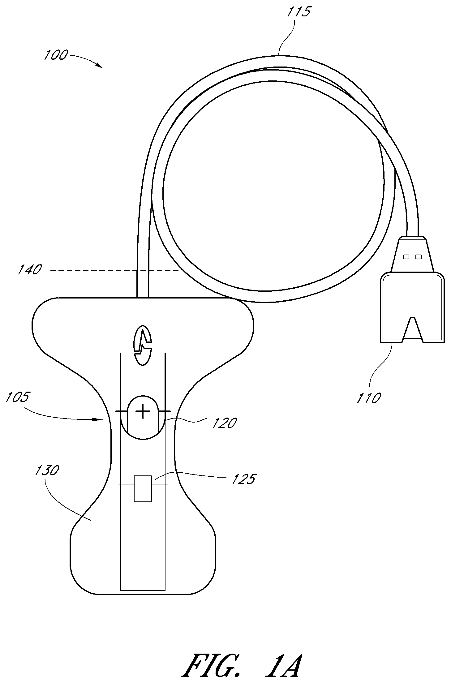
FIG. 1A illustrates an example non-invasive physiological sensor which can be used with a sensor refurbishing process according to embodiments of the disclosure;
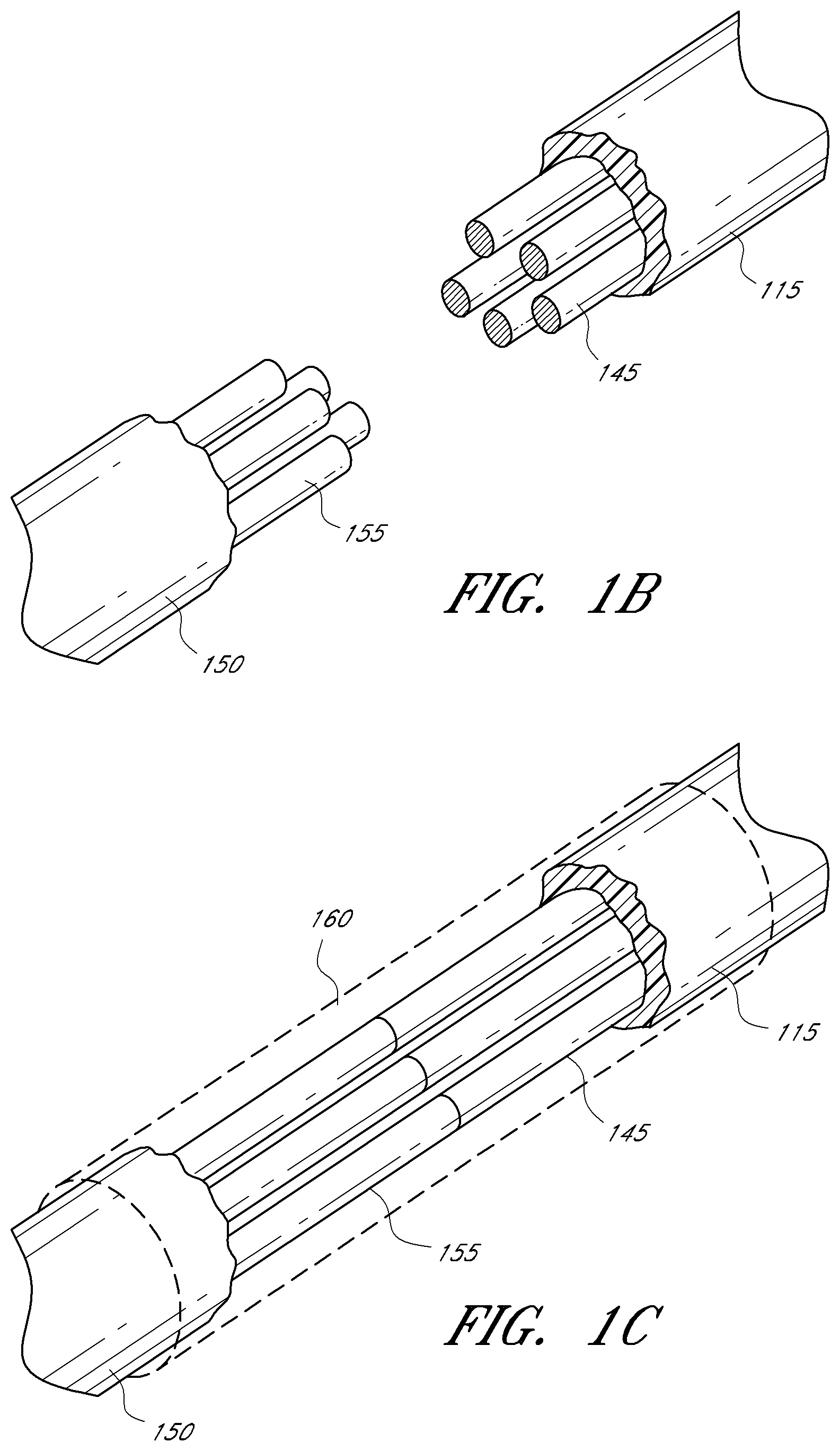
FIGS. 1B and 1C illustrate the attachment of a new sensor assembly to a reused sensor cable of FIG. 1A;
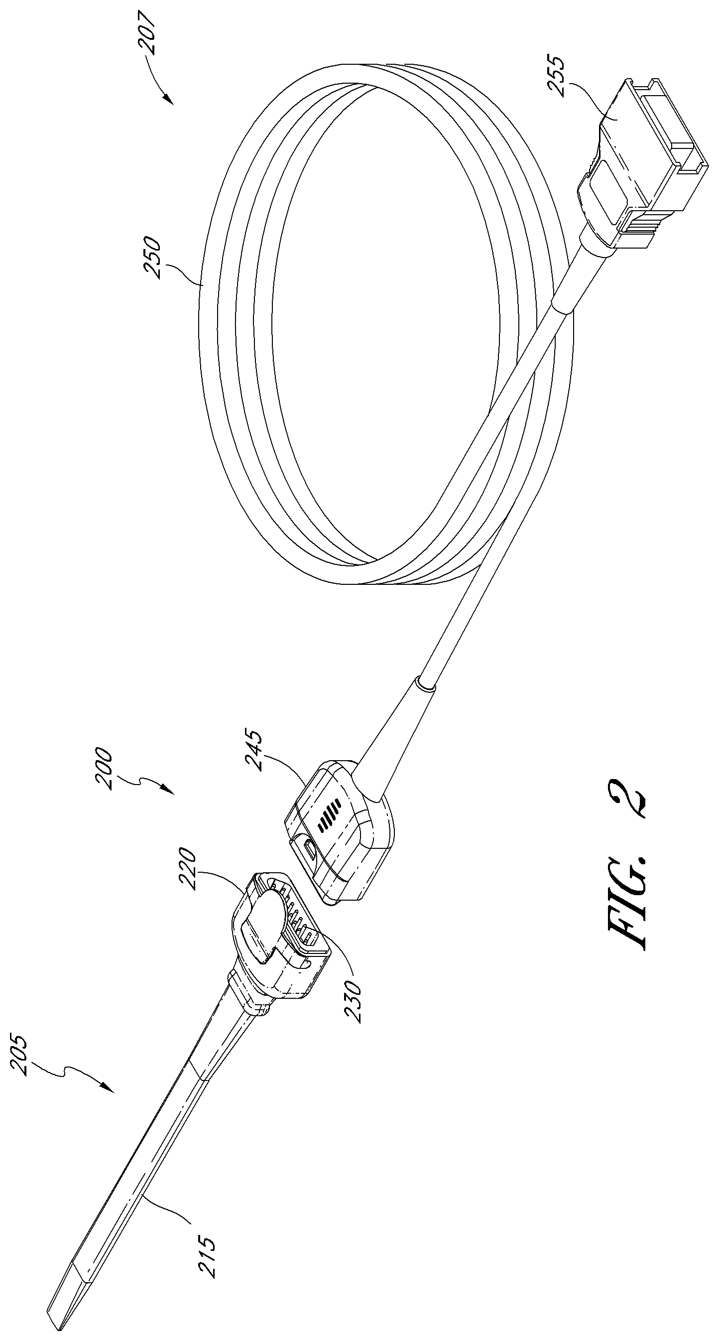
FIG. 2 illustrates a perspective view of a sensor embodiment having a detachable sensor assembly usable in a refurbishing process;
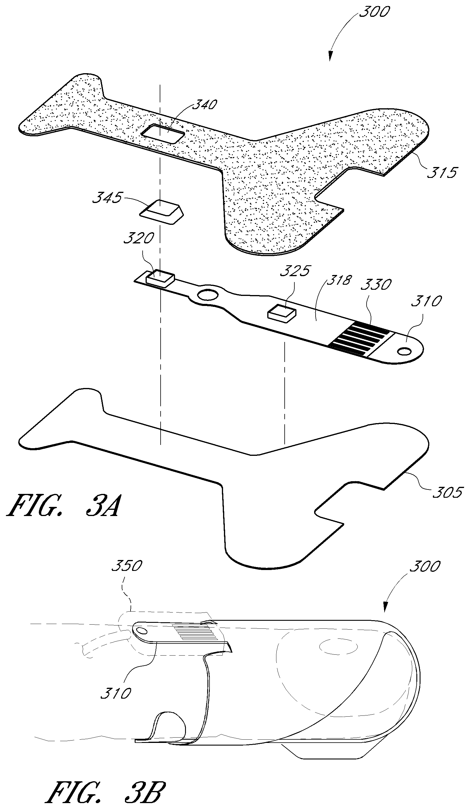
FIGS. 3A illustrates an exploded perspective view of a disposable sensor assembly usable in a refurbishing process;
FIG. 3B illustrates the disposable sensor of FIG. 3A attached to a tissue site and a cable assembly
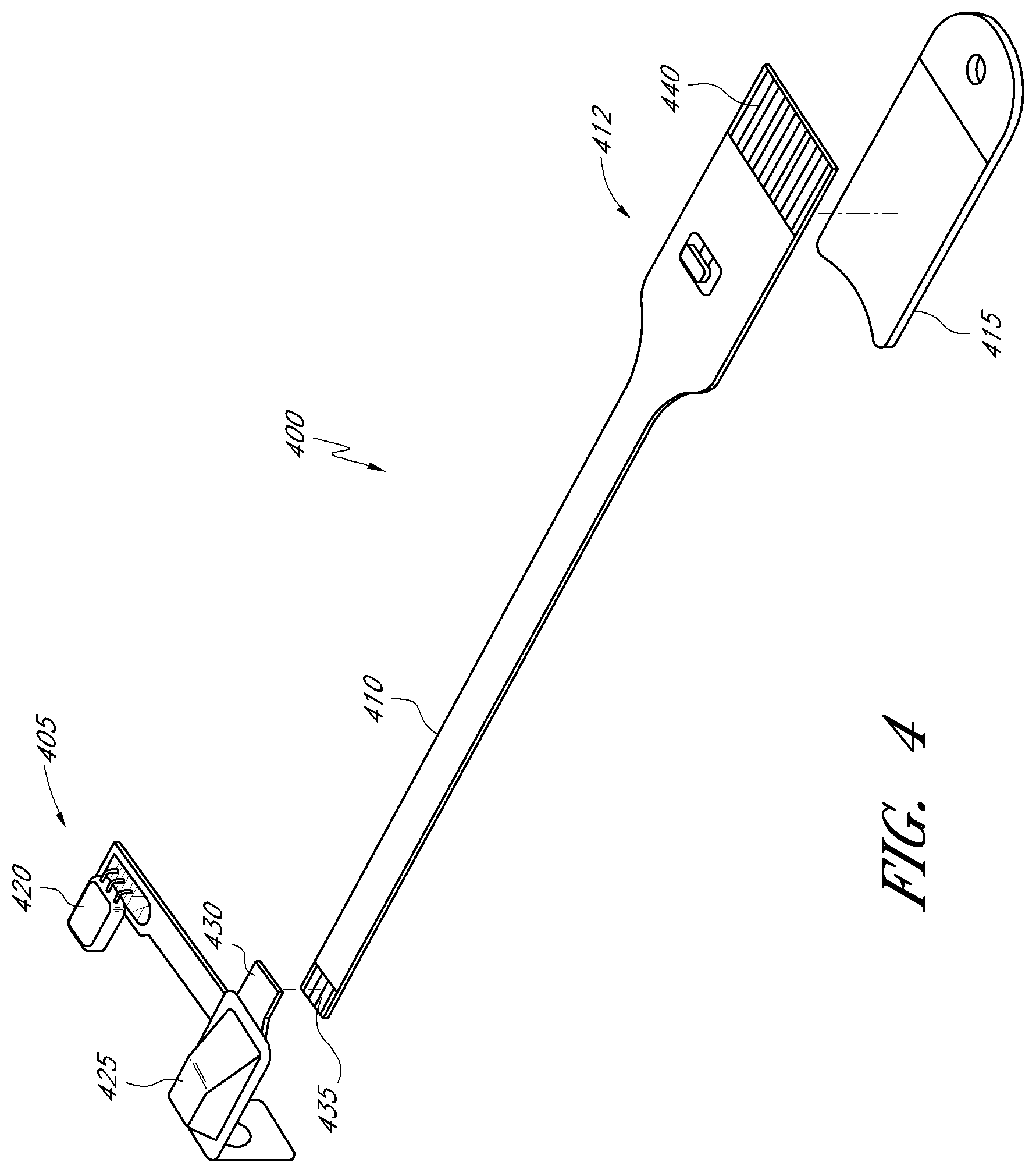
FIG. 4 illustrates a perspective view of a neonate sensor assembly with a detachable sensor portion usable in a refurbishing process;
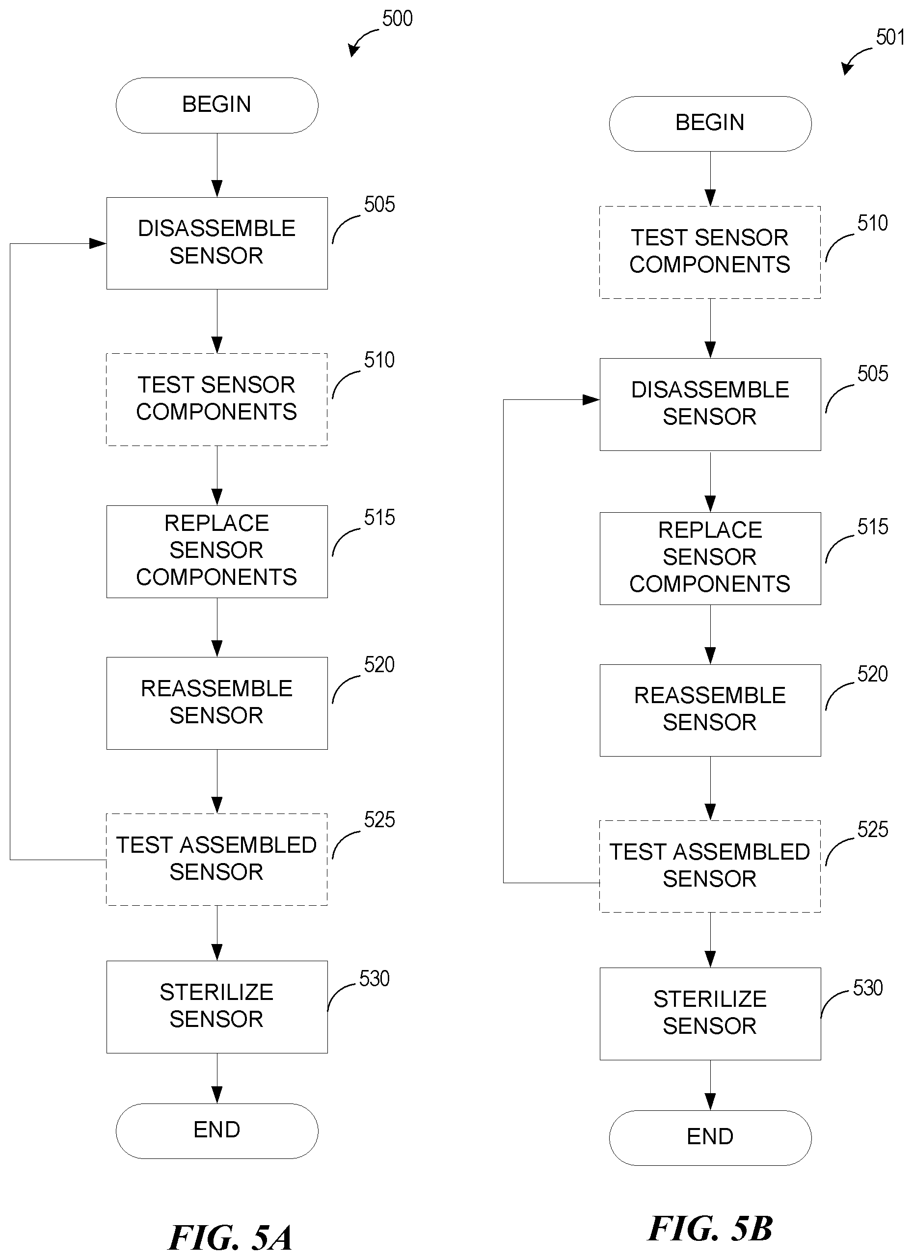
FIGS. 5A and 5B illustrate flow charts for embodiments of a refurbishing process for replacing sensor components;
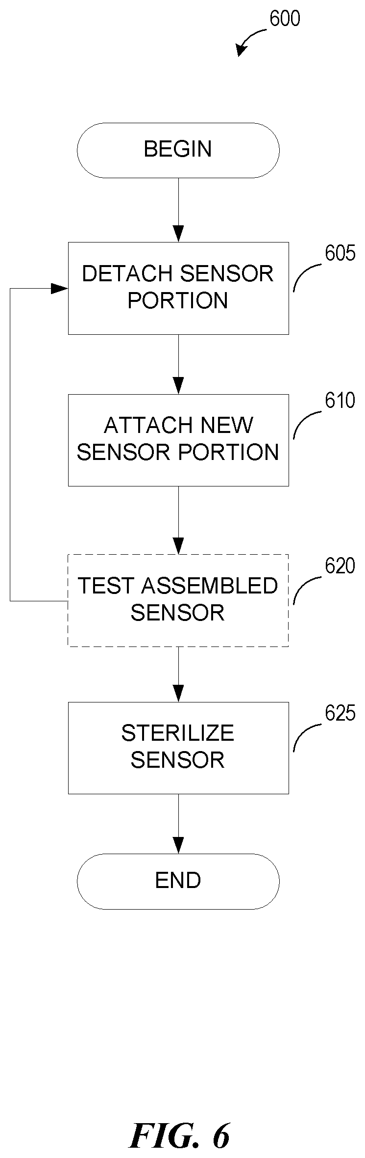
FIG. 6 illustrates another embodiment of a refurbishing process for sensors comprising replaceable modular assemblies;
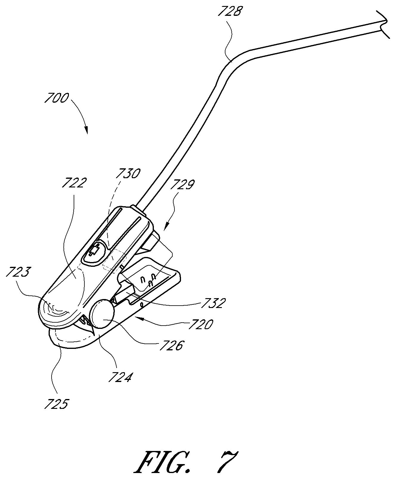
FIG. 7 illustrates a perspective view of one embodiment of reusable sensor usable in a refurbishing process according to embodiments of the disclosure;
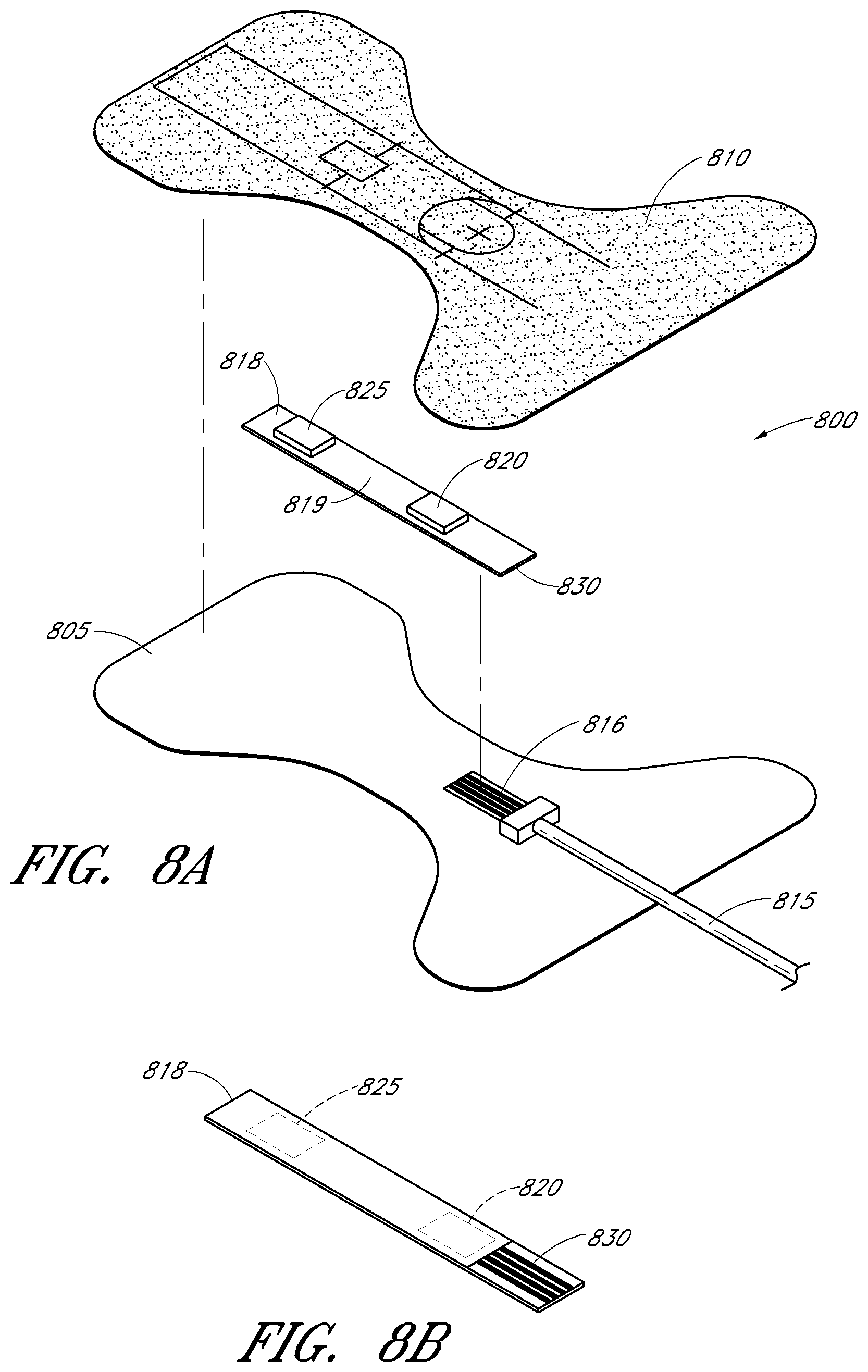
FIG. 8A illustrates an exploded perspective view of an embodiment of a disposable sensor 800 usable in a refurbishing process according to embodiments of the disclosure;
FIG. 8B illustrates a perspective view of the bottom side of the sensor portion of FIG. 8A; and
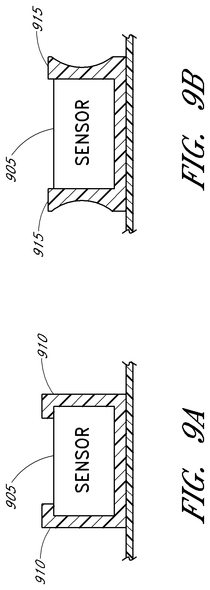
FIGS. 9A and 9B illustrate embodiments of mechanical sensor component holders.
DETAILED DESCRIPTION
Reprocessing includes operations performed to render a used reusable or single-use device patient-ready or to allow an unused product that has been opened to be patient-ready. Reprocessing can be done in-house or by a third-party reprocessor. Whether reprocessesing is done in-house or through a third party, reprocessing generally involves cleaning, sterilization, function testing and/or replacement of components.
In this context, cleaning can mean removal of visible contaminants and environmental debris (including microscopic particles of tissue, body waste, body fluids, dirt, and/or dust). Function testing verifies that a device will perform as intended. Sterilization in the context of reprocessing can mean meeting domestic and/or international sterilization standards, such as meeting a sterility assurance level of 10-6 (i.e. a theoretical one in a million chance that an organism could survive).
FIG. 1A illustrates a top view of an example non-invasive physiological sensor 100 which can be used with a sensor refurbishing process according to embodiments of the disclosure. In certain embodiments, the sensor 100 may allow for the measurement of blood constituents and related parameters, including oxygen saturation, HbCO, HBMet and/or pulse rate. The sensor 100 may advantageously be a non-invasive optical sensor capable of emitting light and outputting one or more signals indicative of attenuation of that light by body tissue. For example, the sensor 100 may be a pulse oximeter sensor including, for example, a red emitter, an infrared emitter, and a photodiode detector. The sensor 100 may be attached to a patient's finger, earlobe, or foot. For a finger, the sensor can be configured so that the emitters project light from one side of the finger, through the outer tissue of the finger, and into the blood vessels and capillaries contained inside. The photodiode can be positioned at the opposite side of the finger to detect the emitted light as it emerges from the outer tissues of the finger. The photodiode can generate a signal based on the emitted light and relay that signal to the sensor 100. The sensor 100 can determine blood oxygen saturation by, for example, computing the differential absorption by the arterial blood of the two or more wavelengths emitted by the sensor.
In certain embodiments, the sensor 100 can be adapted to attach to a tissue site. The sensor 100 can include a sensor assembly 105, a patient monitor connector 110, a sensor cable 115 operatively connecting the sensor assembly 105 and a monitor connector 110. The monitor connector 110 can be adapted to connect to a patient monitor which may include a display providing readouts of measured parameters, such as oxygen saturation, pulse rate, HbCO and/or HbMet to name a few. The sensor assembly 105 can comprise one or more emitters 120 and a detector 125. In certain embodiments, the sensor 100 utilizes an adhesive attachment mechanism 130, such as an adhesive layer, for attaching the sensor 100 to a tissue site. In some embodiments, the sensor can be disposable, re-usable, or partially re-usable and partially disposable.
After the sensor 100 is used on a patient, the used sensor can be refurbished through a refurbishing process. Typically, refurbishing or reprocessing of medical sensors can include disassembling sensors into sub-components, testing sensor components, replacing sensor components, reassembly of the components, testing of the sensor and/or sterilization of the sensor. In some embodiments of the reprocessing process, the entire sensor assembly 105 can be replaced, reusing only the cable 115 and monitor connector 110. In certain embodiments, the cable 115 and/or monitor connector 110 can also be replaced. In some embodiments, only portions of the sensor assembly 105, such as the sensing components, 120, 125 are replaced.
In some embodiments, the whole sensor assembly 105 is replaced. Replacing the whole sensor assembly 105 can reduce or eliminate the need to disassemble the sensor and/or test components during the refurbishing process. For example, the replacement sensor can be pre-tested and/or calibrated beforehand, such as during production, so that testing the sensor components is not required. During reprocessing, the old sensor assembly 105 can be detached from the cable 115, for example, by cutting along a section of the cable 140. The cable 115 can be cut along any section, but preferably is cut near the sensor assembly 105 so that a larger portion of the cable 115 can be reused. After the old sensor assembly 105 is removed, a new sensor assembly is attached to the old cable and tested to determine whether the sensor 100 operates correctly.
In some embodiments, the new sensor assembly includes a cable portion, typically of short length, for attachment to a reprocessed cable. In some embodiments, the cable portion can terminate in a connector for simplified attachment to the reprocessed cable.
FIGS. 1B and 1C illustrate the attachment of a new sensor assembly to a reused sensor cable 115 of FIG. 1A. The sensor cable 115 having a number of wires 145 is attached to a new sensor assembly having a number of wires 155. In one embodiment, the sensor assembly 150 includes a cable portion extending from the sensor assembly containing the sensor assembly wires 155. In one embodiment, at least part of the cable covering the wires 145, 155 is removed to expose the wires 145, 155 for easier access.
In FIG. 1C, the wires 145, 155 are attached to operatively connect the sensor cable 115 and the sensor assembly 150. The connection can be both mechanical and electrical. Attachment of the wires 145, 155 can be through soldering, pressure, tying, adhesive and/or the like. A cable covering 160 can be applied over the connection area to cover exposed wires and/or strengthen the mechanical connection between the cable 115 and the sensor assembly 150.
Although disclosed with reference to the above sensor 100, an artisan will recognize from the disclosure herein a wide variety of oximeter sensors, optical sensors, noninvasive sensors, medical sensors, disposable sensors, reusable sensors or the like that may benefit from embodiments of the refurbishing process disclosed herein.
FIG. 2 illustrates a perspective view of a sensor embodiment 200 having a detachable sensor assembly 205 usable in a refurbishing process. The sensor 200 includes the sensor assembly 205 and a cable assembly 207. The sensor assembly 205 includes a sensor, a cable 215 and a connector 220. The cable assembly includes a connector 245, a cable 250 and a monitor connector 255. The sensor connector 220 is attachable to the cable connector 245. The connectors 220, 245 form a releasable mechanical and electrical connection between the sensor assembly and the cable assembly. The connectors 220, 245 can include pins 230 and corresponding pin connectors for forming an electrical connection between the sensor portion 205 and cable portion 207. Connector assemblies are disclosed in U.S. application Ser. No. 12/248,856 assigned to Masimo Corp. and is incorporated by reference herein.
During reprocessing, the connectors 220, 245 facilitate replacement of either the sensor assembly 205 or the cable assembly 207 of the sensor 200. For example, the sensor portion 205 can be replaced whole by detaching the old sensor assembly 205 from the cable assembly 207 via the sensor connector 220 and replacing with a new sensor assembly by attaching the new sensor connector to the old cable connector 245. The use of a connector also allows replacement of the sensor assembly 205 on-site, for example at a hospital. The sensor assembly 205 can then be sent for refurbishing without also sending the cable assembly, thus reducing shipping costs.
FIG. 3A illustrates an exploded perspective view of a disposable sensor assembly 300. The sensor assembly includes one or more tape layers 305, 315 and a sensor portion 310. The sensor portion 310 includes a base material 318, one or more sensing components 320, 325 such as emitters and/or detectors, and an electrical connector 330. The sensor portion can further include a sensor cover 345 for one or more of the sensing components. Sensor components can be replaced individually or together as part of the sensor portion 310.
In one embodiment, the base material 318, preferably a flexible material, comprises a flex circuit. The flex circuit can comprise a copper/MYLAR.TM. or copper/Capton.TM. laminant, or similar material. Alternatively, the flex circuit can be formed by depositing a conductive ink on MYLAR.TM., polyester, or plastic film. The flex circuit allows electrical communication between the sensing components 320, 325 and electrical connector 330 through the conductive material on the flex circuit.
The sensing components 320, 325 can be attached to the base material 318 through pressure sensitive adhesive (PSA), solder, clip holder, pressure fit or the like. In one embodiment, the emitter and detector are placed such that the transmission and detection field of view are through detector and emitter windows formed on the base material.
In one embodiment, the sensing components 320, 325 are attached to the flex-circuit using pressure or thermally sensitive adhesive configured to provide a temporary bond, advantageously allowing the sensing components 320, 325 to be detached from the sensor portion 310 by pulling the sensing components from the base material 318. As will be apparent, other attachment methods can be used that facilitate removal of sensor components in order to simplify the refurbishing process, such as nodular metal paste, mechanical attachments, or the like.
In another embodiment, the sensing components are attached to the flex-circuit using low temperature solder paste. The sensing components can be desoldered from the flex circuit. The solder can be reheated and reused or new solder can be dispensed on contacts for the detector connections and/or emitter connections in order to attach new sensing components. The solder operation is preferably performed through a direct heat reflow of the low temperature solder.
The sensor portion 310 can further comprise a flex circuit shield including an insulator film, conductive and/or non-conductive PSA. When attached to a flex circuit, a flex circuit shield can insulate the signal traces of the flex circuit from the metallization of the flex circuit shield to prevent short circuits. The sensor portion 310 can be attached to a base layer 305. In one embodiment, the base layer comprises Avery base material. Each side of the base layer can be coated with PSA adhesive.
A face stock 315 can be attached to the base layer 305 such that the sensor portion 310 is secured between the face stock and the base material. In one embodiment, the face stock 315 is advantageously constructed from a non-woven, flexible material, though woven materials can be used. Adhesive can be applied on one side of the face stock. Pressure applied to the face stock 315 bonds the face stock with the base material 305 and/or sensor portion 310. Preferably, the face stock has an aperture 340 to allow a portion of the cover 345 to protrude through the face stock. A release liner can be placed on the other side of the base material from the face stock in order to protect adhesive on that side. The release liner can be removed when the sensor is attached to a patient.
During reprocessing, the sensor assembly 300 can be disassembled into its constituent parts. For example, the face stock 315 can be detached from the base material 305 to expose the sensor portion 310. The sensing components 320, 325 on the sensor portion can be replaced individually or together as part of the sensor portion 310. In one embodiment, the sensing components 320, 325 are replaced individually with at least some of the sensor portion 310 retained. After replacing the sensing components, the sensor can be reassembled. The base layer 305, face stock 315, and/or cover 345 can be replaced or reused. New adhesive can be applied to the sensor assembly 300 and a release liner attached. Once reassembled, the sensor assembly 300 can be sterilized and then packaged for use.
FIG. 3B illustrates the disposable sensor of FIG. 3A attached to a tissue site and a cable assembly. The cable assembly 350 comprises a cable and a connector attachable to the sensor assembly 300 via its sensor connector 330. The cable assembly 350 operatively connects the sensor assembly 300 to a patient monitor. The cable portion 350 can also be reprocessed with the sensor assembly 300 and replaced if defective. However, as the cable portion generally receives less wear than the sensor assembly 300, the cable portion can likely be reused without replacement of components, reducing the cost of reprocessing the sensor.
FIG. 4 illustrates a perspective view of a neonate sensor assembly 400 with a detachable sensor portion 405 usable in a refurbishing process. The sensor includes the sensor portion 405, an elongated body 410, and a connector portion 412. The sensor portion 405 incorporates one or more emitters 420, a detector assembly 425, and a sensor portion pinout 435. The sensor portion pinout 430 is configured to connect with a body pinout 430 so as to mechanically and electrically connect the sensor to the body 410. Connection can be accomplished by solder, adhesive, mechanically such as by tab, sleeve or clip, or by other connection mechanism. The body 410 includes signal traces between the sensor portion pinout 435 and the connector portion 412. The connector portion 412 has a plug portion configured to insert into a mating patient cable connector so as to mechanically and electrically connect the sensor 400 to a patient cable, for example. The connector portion 412 is configured with a connector tab 415 supporting sensor pinouts 440.
As the sensor portion 405 is detachable from the elongate body 410, reprocessing of the sensor is simplified. For example, the sensor portion 405 can be detached from the elongate body and replaced with a new sensor portion 405. By incorporating sensing elements, such as the emitters 420 and the detector 410 on the detachable modular portion, the sensing elements can be easily replaced as a whole rather than individually, thus reducing refurbishing costs and refurbishing time. In one embodiment, the sensing elements can be pre-tested in order to eliminate or reduce the need for testing the sensor elements.
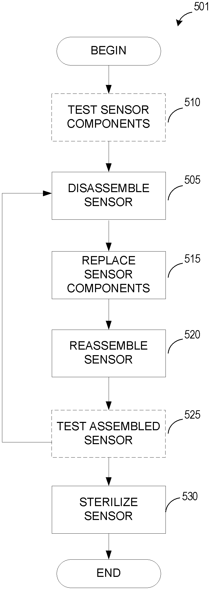
FIGS. 5A, 5B and 6 illustrate flow charts for embodiments of a refurbishing process replacing sensor components. The refurbishing process can be used for the sensors described in FIGS. 1A-4 and FIGS. 7-9B, as well as other types of sensors. In some embodiments, the refurbishing process may be performed by a computing system comprising one or more computing devices, the one or more computing devices configured to perform one or more of the logical blocks described below. The logical blocks of the refurbishing process can be embodied as software, hardware, or a combination of software and hardware of the computing system. For example, the refurbishing process may be embodied in software stored on non-transitory, physical computer storage such as a hard drive, optical disk or flash memory. In some embodiments, the computing system may be part of a refurbishing system comprising one or more machines configured to dissemble sensors, replace sensor components, test sensors and/or sterilize sensors. In one embodiment, the computing system directs or monitors the operation of the refurbishing machines. In one embodiment, the machines operate automatically. In some embodiments, one or more logical blocks may be performed by or directed by a person. For example, the entire refurbishing process may be performed by or directed by one or more persons.
In FIG. 5A the process 500 begins at block 505 with disassembling the sensor, in whole or in part, into subcomponents or individual components. Sensors can be disassembled through desoldering, removing adhesive, detaching connectors, or the like.
At bock 510, the sensor components can optionally be tested. For example, sensor components can be tested to determine if performance is within specification. Sensor components within specification can be reused. Testing of components can be skipped to reduce cost and/or speed up the refurbishing process.
In one embodiment, testing can be conducted before disassembly to determine if the sensor as a whole is within specification. Generally, sensors need to meet specified sensor performance criteria determined by the manufacturer or purchaser. By testing before disassembly, out-of-specification sensing components can be detected beforehand and the sensing portion can be replaced as a whole without disassembly. In contrast, by testing after disassembly, a specific out-of-spec component can be identified, allowing reuse of the other parts of the sensing portion that are still in-spec. The timing of the testing can be chosen based on the costs of disassembly versus the savings from reusing still in-specification components. After block 510, the refurbishing process proceeds to block 515.
At block 515, sensor components are replaced. In one embodiment, sensor components are replaced if determined to be out-of-spec. In another embodiment, no testing is performed and pre-determined sensor components are replaced. For example, as part of the refurbishing process, all or some of the sensing components can be replaced without testing. Advantageously, predetermined replacement of components can eliminate or reduce the need for testing or disassembly. After block 515, the refurbishing process proceeds to block 520.
At block 520, the sensor is reassembled. Reassembly can comprise soldering, adhesively connecting, and/or mechanically connecting various components together. Typically, the assembled sensor comprises both new components and at least some of the original components. After block 520, the refurbishing process proceeds to block 525.
At block 525, the assembled sensor is optionally tested to determine if the sensor works and is within specification for the particular sensor type. Testing can include testing of the assembly of the sensor components, testing of the electrical connection between sensor components, testing of sensor performance, and/or the like. If the test fails, the sensor can reenter the refurbishing process at block 505 or can be disposed of. If the sensor passes the test, the refurbishing process proceeds to block 530. In some embodiments, testing may be unnecessary during reprocessing, such as when the sensor components are pre-tested before assembling the sensor.
At block 530, the sensor is sterilized. Sterilization can occur before or after the sensor is packaged for use. The sensor can also be cleaned before sterilization. After sterilization, the sensor can be packaged for use, ending the refurbishing process.
FIG. 5B generally illustrates the same process as FIG. 5A, except that optional block 510, testing of the sensor components, occurs before block 505, disassembling the sensor. Testing of the components can be individually, by group, or of the whole sensor. By testing the sensor components before dissembling the sensor, components that need to be replaced can be identified before disassembly, potentially reducing the number of components to be detached.
FIG. 6 illustrates another embodiment of a refurbishing process 600 for a sensor comprising replaceable modular assemblies. The refurbishing process can be used for the sensors described in FIGS. 1A-4 and FIGS. 7-9B, as well as other types of sensors. In one embodiment, the sensor is composed of modules, such as a sensor assembly and a cable assembly. In some embodiments, a sensor assembly comprises a modular sensor portion. The sensor portion can further comprise adhesive portions, a sensor body, and/or electrical or mechanical connectors. During reprocessing, the modular assembly is replaced. By replacing the modular assembly as a whole, the need for testing sensor components can be reduced or eliminated, thus reducing costs. For example, in FIG. 1A, the sensor assembly 100 can be replaced as whole. Likewise with the sensor assembly 205 of FIG. 2, the sensor portion 310 of FIG. 3, and the sensor portion 405 of FIG. 4. Furthermore, modular assemblies can be pre-tested during their production, simplifying the refurbishing process.
At block 605, the refurbishing process begins by detaching the modular assembly from the sensor. In some embodiments, a sensor portion 405 (in FIG. 4) is detached from a sensor assembly 400. In some embodiments, a sensor assembly 105 (in Fig.1) is detached from a cable assembly 140, for example, by cutting the sensor assembly from the cable. In some embodiments, detaching of the modular assembly can be simplified by using a connector 220 (in FIG. 2), 405 (in FIG. 4). After block 605, the refurbishing process proceeds to block 610.
At block 610, the modular assembly is attached to the sensor. The attached modular assembly can be a sensor portion attached to a sensor assembly or a sensor assembly attached to a cable assembly. Typically, the assembled sensor comprises both new components and at least some of the original components. Generally, the cable assembly receives less wear and tear during use and is likely to perform within specification without replacement. However, in some situations, the cable assembly can be replaced in addition or instead of the sensor portion or assembly. Reattachment can be accomplished through use of a connecter, splicing of wires, adhesive connection, soldering, or the like.
As replacement is accomplished by replacing groups of components, such as a sensor assembly, cable assembly, and/or a sensor portion, reassembly of the sensor is simplified in comparison to replacement of individual components. If component costs are cheap relative to assembly and disassembly cost, the simplified reassembly can reduce the costs of refurbishing. After block 610, the refurbishing process proceeds to block 620.
At block 620, the assembled sensor is optionally tested to determine if the sensor works and is within specification for the particular sensor type. Testing can include testing of the assembly of the sensor components, testing of the electrical connection between sensor components, testing of sensor performance, and/or the like. If the test fails, the sensor can reenter the refurbishing process at block 605 or can be disposed of. If the sensor passes the test, the refurbishing process proceeds to block 625. In some embodiments, testing during reprocessing may be unnecessary, such as when the sensor portion is pre-tested before assembling the sensor.
At block 625, the sensor is sterilized. Sterilization can occur before or after the sensor is packaged for use. The sensor can also be cleaned before sterilization. Once packaged, the sensor can be delivered to an end-user.
FIG. 7 illustrates a perspective view of one embodiment of reusable sensor 700 usable in a refurbishing process according to embodiments of the disclosure. The reusable sensor can be a clip-type sensor including an upper housing 722, a lower housing 724 and a hinge element 726. The upper and lower housings 722, 724 house electrical and/or optical components (not shown) of the non-invasive physiological sensor 720. For example, the upper and lower housings 722, 724 can house sensing elements 730, 732, such as one or more light emitters or LEDs and a detector or light sensor. The sensor 720 can be connected to a patient monitor via a cable 728. For example, the detector outputs a signal to the monitor over the cable 728 which then processes the signal to provide a numerical readout of physiological parameters such as oxygen saturation (SpO2) and pulse rate.
During refurbishing, one or both the sensing elements 730, 732 can be removed and/or replaced from the reusable sensor 700. The sensor elements can be tested separately or as part of the reusable sensor. Other components of the reusable sensor can also be replaced during the refurbishing process,
FIG. 8A illustrates an exploded perspective view of an embodiment of a disposable sensor 800 usable in a refurbishing process according to embodiments of the disclosure. The sensor includes one or more tape layers 805, 810, a cable assembly 815, and a sensor portion 818. The cable assembly 815 can terminate at an electric connector 816 and can be attached to one of the tape layers 805. The sensor portion 818 includes a base material 819, one or more sensing components 820, 825 such as emitters and/or detectors, and an electrical connector 830. Sensor components can be replaced individually or together as part of the sensor portion 818. The sensor portion's electrical connector 830 can attach to the cable assembly's electrical connector 816 to form an electrical connection between the sensor portion and the cable. The sensor portion 818 can be attached to the cable assembly 815 and/or one or more tape layers 805, 810 by various ways, such as adhesive, solder, clip holder, pressure fit and/or the like. In one embodiment, the sensor assembly 815 and sensor portion 818 are sandwiched between a first layer 805 and a second 810 tape layer.
As the sensor portion 818 is detachable from the cable assembly 815 and/or tape layers 805, 810, reprocessing of the sensor is simplified. For example, the sensor portion 818 can be detached from the elongate body and replaced with a new sensor portion. By incorporating sensing components 820, 825, such as emitters and/or detectors on the detachable modular portion, the sensing components can be easily replaced as a whole rather than individually, thus reducing refurbishing costs and refurbishing time. In one embodiment, the sensing components can be pre-tested in order to eliminate or reduce the need for testing the sensing components during the refurbishing process.
FIG. 8B illustrates a perspective view of the bottom side of the sensor portion 818 of FIG. 8A. The electrical connector 830 is shown on the bottom side of the sensor portion. However, the electrical connector can also be placed on the top side.
FIGS. 9A and 9B illustrate embodiments of mechanical sensor component holders. FIG. 9A illustrates a cross-sectional view of a sensor component attached to a sensor via a clip holder. The sensor component 905 is held in place by one or more clip arms 910 extending over the sensor component. The sensor component 905 can be detached for replacement by pushing the clip arms 910 outward and removing the sensor component 905.
FIG. 9B illustrates a cross-sectional view of a sensor component attached to a sensor via a pressure or snug fit holder. The sides of the holder 915 are biased inwards, holding the sensor component together via pressure. The sensor component 905 can be detached for replacement by pushing the sides of the holder 915 outward and removing the sensor component 905.
The reusable nature of the mechanical holders allows replacement of the sensor component without requiring new attachment mechanisms, such as replacement adhesive or solder, thus reducing refurbishing costs and/or complexity. As will be apparent, other types of mechanical holders can be used and mechanical holders can be used with both disposable and reusable sensors.
Depending on the embodiment, certain acts, events, or functions of any of the algorithms described herein can be performed in a different sequence, can be added, merged, or left out all together (e.g., not all described acts or events are necessary for the practice of the algorithms). Moreover, in certain embodiments, acts or events can be performed concurrently, e.g., through multi-threaded processing, interrupt processing, or multiple processors or processor cores or on other parallel architectures, rather than sequentially.
The various illustrative logical blocks, modules, and algorithm steps described in connection with the embodiments disclosed herein can be implemented as electronic hardware, computer software, or combinations of both. To clearly illustrate this interchangeability of hardware and software, various illustrative components, blocks, modules, and steps have been described above generally in terms of their functionality. Whether such functionality is implemented as hardware or software depends upon the particular application and design constraints imposed on the overall system. The described functionality can be implemented in varying ways for each particular application, but such implementation decisions should not be interpreted as causing a departure from the scope of the disclosure.
The various illustrative logical blocks and modules described in connection with the embodiments disclosed herein can be implemented or performed by a machine, such as a general purpose processor, a digital signal processor (DSP), an application specific integrated circuit (ASIC), a field programmable gate array (FPGA) or other programmable logic device, discrete gate or transistor logic, discrete hardware components, or any combination thereof designed to perform the functions described herein. A general purpose processor can be a microprocessor, but in the alternative, the processor can be a controller, microcontroller, or state machine, combinations of the same, or the like. A processor can also be implemented as a combination of computing devices, e.g., a combination of a DSP and a microprocessor, a plurality of microprocessors, one or more microprocessors in conjunction with a DSP core, or any other such configuration.
The steps of a method, process, or algorithm described in connection with the embodiments disclosed herein can be embodied directly in hardware, in a software module executed by a processor, or in a combination of the two. A software module can reside in RAM memory, flash memory, ROM memory, EPROM memory, EEPROM memory, registers, hard disk, a removable disk, a CD-ROM, or any other form of computer-readable storage medium known in the art. An exemplary storage medium can be coupled to the processor such that the processor can read information from, and write information to, the storage medium. In the alternative, the storage medium can be integral to the processor. The processor and the storage medium can reside in an ASIC. The ASIC can reside in a user terminal. In the alternative, the processor and the storage medium can reside as discrete components in a user terminal. Data may be stored in various types of data stores, such as tables, files, databases, directories or the like.
Conditional language used herein, such as, among others, "can," "could," "might," "may," "e.g.," and the like, unless specifically stated otherwise, or otherwise understood within the context as used, is generally intended to convey that certain embodiments include, while other embodiments do not include, certain features, elements and/or states. Thus, such conditional language is not generally intended to imply that features, elements and/or states are in any way required for one or more embodiments or that one or more embodiments necessarily include logic for deciding, with or without author input or prompting, whether these features, elements and/or states are included or are to be performed in any particular embodiment. Also, the term "or" is used in its inclusive sense (and not in its exclusive sense) so that when used, for example, to connect a list of elements, the term "or" means one, some, or all of the elements in the list.
Various reprocessing and refurbishing processes have been disclosed in detail in connection with various embodiments. These embodiments are disclosed by way of examples only and are not to limit the scope of the claims that follow. Indeed, the novel methods and systems described herein can be embodied in a variety of other forms; furthermore, various omissions, substitutions and changes in the form of the methods and systems described herein can be made without departing from the spirit of the inventions disclosed herein. The claims and their equivalents are intended to cover such forms or modifications as would fall within the scope and spirit of certain of the inventions disclosed herein. One of ordinary skill in the art will appreciate the many variations, modifications and combinations. For example, the various embodiments of the reprocessing and refurbishing process can be used with sensors that can measure any type of physiological parameter and with both disposable and reusable sensors.
* * * * *
D00000
D00001
D00002
D00003
D00004
D00005
D00006
D00007
D00008
D00009
D00010
XML
uspto.report is an independent third-party trademark research tool that is not affiliated, endorsed, or sponsored by the United States Patent and Trademark Office (USPTO) or any other governmental organization. The information provided by uspto.report is based on publicly available data at the time of writing and is intended for informational purposes only.
While we strive to provide accurate and up-to-date information, we do not guarantee the accuracy, completeness, reliability, or suitability of the information displayed on this site. The use of this site is at your own risk. Any reliance you place on such information is therefore strictly at your own risk.
All official trademark data, including owner information, should be verified by visiting the official USPTO website at www.uspto.gov. This site is not intended to replace professional legal advice and should not be used as a substitute for consulting with a legal professional who is knowledgeable about trademark law.