Systems, apparatuses, and methods for a hardware and software system to automatically decompose a program to multiple parallel threads
Sager , et al.
U.S. patent number 10,725,755 [Application Number 15/615,798] was granted by the patent office on 2020-07-28 for systems, apparatuses, and methods for a hardware and software system to automatically decompose a program to multiple parallel threads. This patent grant is currently assigned to Intel Corporation. The grantee listed for this patent is Intel Corporation. Invention is credited to Jayaram Bobba, Howard H. Chen, Jeffrey J. Cook, Jason A. Domer, Ron Gabor, Ho-Seop Kim, Tin-Fook Ngai, Joseph Nuzman, Leeor Peled, Shlomo Raikin, David J. Sager, Ruchira Sasanka, Omar M. Shaikh, Suresh Srinivas, Youfeng Wu, Koichi Yamada.

View All Diagrams
| United States Patent | 10,725,755 |
| Sager , et al. | July 28, 2020 |
Systems, apparatuses, and methods for a hardware and software system to automatically decompose a program to multiple parallel threads
Abstract
Systems, apparatuses, and methods for a hardware and software system to automatically decompose a program into multiple parallel threads are described. In some embodiments, the systems and apparatuses execute a method of original code decomposition and/or generated thread execution.
| Inventors: | Sager; David J. (Portland, OR), Sasanka; Ruchira (Hillsboro, OR), Gabor; Ron (Hertzliya, IL), Raikin; Shlomo (Moshav Sde Eliezer, IL), Nuzman; Joseph (Haifa, IL), Peled; Leeor (Haifa, IL), Domer; Jason A. (Hillsboro, OR), Kim; Ho-Seop (Portland, OR), Wu; Youfeng (Palo Alto, CA), Yamada; Koichi (Los Gatos, CA), Ngai; Tin-Fook (San Jose, CA), Chen; Howard H. (Sunnyvale, CA), Bobba; Jayaram (Portland, OR), Cook; Jeffrey J. (Portland, OR), Shaikh; Omar M. (Portland, OR), Srinivas; Suresh (Portland, OR) | ||||||||||
|---|---|---|---|---|---|---|---|---|---|---|---|
| Applicant: |
|
||||||||||
| Assignee: | Intel Corporation (Santa Clara,
CA) |
||||||||||
| Family ID: | 46314724 | ||||||||||
| Appl. No.: | 15/615,798 | ||||||||||
| Filed: | June 6, 2017 |
Prior Publication Data
| Document Identifier | Publication Date | |
|---|---|---|
| US 20180060049 A1 | Mar 1, 2018 | |
Related U.S. Patent Documents
| Application Number | Filing Date | Patent Number | Issue Date | ||
|---|---|---|---|---|---|
| 12978557 | Dec 25, 2010 | 9672019 | |||
| 12646815 | Dec 23, 2009 | ||||
| 12624804 | Dec 9, 2014 | 8909902 | |||
| 61200103 | Nov 24, 2008 | ||||
| Current U.S. Class: | 1/1 |
| Current CPC Class: | G06F 9/3851 (20130101); G06F 9/54 (20130101); G06F 11/3636 (20130101); G06F 11/3648 (20130101); G06F 8/4442 (20130101); G06F 11/3612 (20130101); G06F 9/3861 (20130101); G06F 9/3842 (20130101); G06F 2213/0038 (20130101) |
| Current International Class: | G06F 8/41 (20180101); G06F 9/38 (20180101); G06F 9/54 (20060101); G06F 11/36 (20060101) |
References Cited [Referenced By]
U.S. Patent Documents
| 5345576 | September 1994 | Lee et al. |
| 5349651 | September 1994 | Hetherington et al. |
| 5524208 | June 1996 | Finch et al. |
| 5724565 | March 1998 | Dubey et al. |
| 5752272 | May 1998 | Tanabe |
| 5826089 | October 1998 | Ireton |
| 5835775 | November 1998 | Washington et al. |
| 5872987 | February 1999 | Wade et al. |
| 5890008 | March 1999 | Panwar et al. |
| 5926832 | July 1999 | Wing et al. |
| 5933627 | August 1999 | Parady |
| 5999734 | December 1999 | Willis et al. |
| 6016397 | January 2000 | Ogasawara et al. |
| 6031992 | February 2000 | Cmelik et al. |
| 6077315 | June 2000 | Greenbaum et al. |
| 6157988 | December 2000 | Dowling et al. |
| 6175906 | January 2001 | Christie |
| 6219833 | April 2001 | Solomon et al. |
| 6289506 | September 2001 | Kwong et al. |
| 6314491 | November 2001 | Freerksen et al. |
| 6327704 | December 2001 | Mattson, Jr. et al. |
| 6415379 | July 2002 | Keppel et al. |
| 6430668 | August 2002 | Belgard |
| 6438747 | August 2002 | Schreiber et al. |
| 6542862 | April 2003 | Safford et al. |
| 6615340 | September 2003 | Wilmot, II |
| 6622301 | September 2003 | Hirooka |
| 6631514 | October 2003 | Le |
| 6711667 | March 2004 | Ireton |
| 6718839 | April 2004 | Chaudhry et al. |
| 6884171 | April 2005 | Eck et al. |
| 6976131 | December 2005 | Pentkovski et al. |
| 7010787 | March 2006 | Sakai |
| 7111096 | September 2006 | Banning et al. |
| 7178137 | February 2007 | Peak et al. |
| 7216202 | May 2007 | Chaudhry et al. |
| 7269825 | September 2007 | Adcock |
| 7290253 | October 2007 | Agesen |
| 7343479 | March 2008 | Knebel et al. |
| 7346902 | March 2008 | Dutt et al. |
| 7350200 | March 2008 | Lueh et al. |
| 7373640 | May 2008 | English et al. |
| 7376800 | May 2008 | Choquette et al. |
| 7446773 | November 2008 | Alben |
| 7466316 | December 2008 | Alben |
| 7503039 | March 2009 | Ohara et al. |
| 7506217 | March 2009 | Borin et al. |
| 7516453 | April 2009 | Bugnion |
| 7603664 | October 2009 | Dutt et al. |
| 7640399 | December 2009 | Lepak et al. |
| 7644210 | January 2010 | Banning et al. |
| 7734895 | June 2010 | Agarwal |
| 7757221 | July 2010 | Zheng et al. |
| 7765536 | July 2010 | Gordy |
| 7814486 | October 2010 | Papakipos et al. |
| 7962724 | June 2011 | Ali |
| 8127121 | February 2012 | Yates et al. |
| 8136102 | March 2012 | Papakipos et al. |
| 8146106 | March 2012 | Kim et al. |
| 8181168 | May 2012 | Lee et al. |
| 8209517 | June 2012 | Rozas et al. |
| 8214808 | July 2012 | Day et al. |
| 8255882 | August 2012 | Zhang et al. |
| 8296749 | October 2012 | Zhao et al. |
| 8387034 | February 2013 | Gordy |
| 8418179 | April 2013 | Papakipos et al. |
| 8463589 | June 2013 | Clark et al. |
| 8464035 | June 2013 | Dixon et al. |
| 8479176 | July 2013 | Ottoni et al. |
| 8521944 | August 2013 | Matas |
| 8527973 | September 2013 | Little et al. |
| 8762127 | June 2014 | Winkel et al. |
| 8789031 | July 2014 | Liu et al. |
| 8893280 | November 2014 | Jung et al. |
| 8909902 | December 2014 | Latorre et al. |
| 8935678 | January 2015 | Wu et al. |
| 9317263 | April 2016 | Chee et al. |
| 9329872 | May 2016 | Guerrero et al. |
| 9417855 | August 2016 | Kanhere et al. |
| 2002/0013892 | January 2002 | Gorishek et al. |
| 2002/0045484 | April 2002 | Eck et al. |
| 2002/0065992 | May 2002 | Chauvel et al. |
| 2002/0156977 | October 2002 | Derrick et al. |
| 2003/0014602 | January 2003 | Shibayama et al. |
| 2003/0018684 | January 2003 | Ohsawa et al. |
| 2003/0172253 | September 2003 | Balakrishnan et al. |
| 2003/0221035 | November 2003 | Adams |
| 2004/0003309 | January 2004 | Cai et al. |
| 2004/0059897 | March 2004 | Rose et al. |
| 2004/0073899 | April 2004 | Luk et al. |
| 2004/0078779 | April 2004 | Dutt et al. |
| 2004/0078780 | April 2004 | Dutt et al. |
| 2004/0078785 | April 2004 | Dutt et al. |
| 2004/0107335 | June 2004 | Dua et al. |
| 2005/0086451 | April 2005 | Yates, Jr. |
| 2005/0267996 | December 2005 | O'Connor et al. |
| 2005/0273772 | December 2005 | Matsakis et al. |
| 2006/0005176 | January 2006 | Kawahara |
| 2006/0005179 | January 2006 | Kawahara |
| 2006/0064692 | March 2006 | Sanchez et al. |
| 2006/0136878 | June 2006 | Raghunath |
| 2006/0218432 | September 2006 | Traskov et al. |
| 2006/0294326 | December 2006 | Jacobson et al. |
| 2006/0294508 | December 2006 | Berkowits et al. |
| 2007/0038987 | February 2007 | Ohara et al. |
| 2007/0050555 | March 2007 | Ferren et al. |
| 2007/0079281 | April 2007 | Liao et al. |
| 2007/0079304 | April 2007 | Zheng et al. |
| 2007/0157206 | July 2007 | Rakvic |
| 2007/0169042 | July 2007 | Janczewski et al. |
| 2007/0169046 | July 2007 | Gordy |
| 2007/0174828 | July 2007 | O'Brien |
| 2007/0192545 | August 2007 | Gara et al. |
| 2007/0220525 | September 2007 | State et al. |
| 2007/0226696 | September 2007 | Radhakrishnan et al. |
| 2007/0234315 | October 2007 | Branda et al. |
| 2007/0277021 | November 2007 | O'Connor et al. |
| 2007/0283100 | December 2007 | Asano et al. |
| 2007/0283337 | December 2007 | Kasahara |
| 2007/0283357 | December 2007 | Jeter et al. |
| 2007/0294680 | December 2007 | Papakipos et al. |
| 2007/0294702 | December 2007 | Melvin et al. |
| 2008/0010444 | January 2008 | Hammes |
| 2008/0134159 | June 2008 | Guo et al. |
| 2008/0141012 | June 2008 | Yehia |
| 2008/0141268 | June 2008 | Tirumalai et al. |
| 2008/0163183 | July 2008 | Li et al. |
| 2008/0209389 | August 2008 | Baumgartner et al. |
| 2008/0244538 | October 2008 | Nair et al. |
| 2008/0263324 | October 2008 | Sutardja |
| 2008/0270740 | October 2008 | Wang et al. |
| 2008/0294882 | November 2008 | Jayapala et al. |
| 2009/0019272 | January 2009 | Cypher et al. |
| 2009/0031082 | January 2009 | Ford et al. |
| 2009/0037682 | February 2009 | Armstrong et al. |
| 2009/0064115 | March 2009 | Sheynin et al. |
| 2009/0172353 | July 2009 | Su et al. |
| 2009/0204785 | August 2009 | Yates, Jr. et al. |
| 2009/0217020 | August 2009 | Yourst |
| 2009/0222654 | September 2009 | Hum et al. |
| 2009/0228657 | September 2009 | Hagiwara |
| 2010/0005474 | January 2010 | Sprangle et al. |
| 2010/0026812 | February 2010 | Minatel |
| 2010/0042981 | February 2010 | Dreyer et al. |
| 2010/0050266 | February 2010 | Cheng et al. |
| 2010/0070708 | March 2010 | Maruyama |
| 2010/0122036 | May 2010 | Radovic et al. |
| 2010/0146209 | June 2010 | Burger et al. |
| 2010/0205599 | August 2010 | Vaidya et al. |
| 2010/0235611 | September 2010 | Yamashita |
| 2010/0262812 | October 2010 | Lopez et al. |
| 2010/0269102 | October 2010 | Latorre et al. |
| 2010/0274551 | October 2010 | Das et al. |
| 2010/0274972 | October 2010 | Babayan |
| 2011/0055530 | March 2011 | Henry et al. |
| 2011/0067015 | March 2011 | Takagi et al. |
| 2011/0119526 | May 2011 | Blumrich et al. |
| 2011/0119660 | May 2011 | Tanaka |
| 2011/0131372 | June 2011 | Knippel et al. |
| 2011/0154079 | June 2011 | Dixon et al. |
| 2011/0154090 | June 2011 | Dixon et al. |
| 2011/0167416 | July 2011 | Sager et al. |
| 2011/0225655 | September 2011 | Niemelae et al. |
| 2011/0238955 | September 2011 | Nickolls |
| 2012/0144167 | June 2012 | Yates, Jr. et al. |
| 2012/0233378 | September 2012 | Elteto |
| 2012/0239912 | September 2012 | Maeda et al. |
| 2013/0086299 | April 2013 | Epstein |
| 2013/0185580 | July 2013 | Dixon et al. |
| 2013/0262838 | October 2013 | Al-Otoom et al. |
| 2013/0268742 | October 2013 | Yamada et al. |
| 2013/0283249 | October 2013 | Kanhere et al. |
| 2013/0290693 | October 2013 | Guerrero et al. |
| 2013/0305019 | November 2013 | Caprioli et al. |
| 2013/0311758 | November 2013 | Caprioli et al. |
| 2014/0095832 | April 2014 | Haber et al. |
| 2014/0156933 | June 2014 | Shaikh et al. |
| 2014/0258677 | September 2014 | Sasanka et al. |
| 2014/0281376 | September 2014 | Yamada et al. |
| 2017/0192788 | July 2017 | Margulis et al. |
| 2018/0081684 | March 2018 | Chou et al. |
| 2018/0173291 | June 2018 | Levit-Gurevich et al. |
| 1178941 | Apr 1998 | CN | |||
| 1682181 | Oct 2005 | CN | |||
| 1316882 | Jun 2003 | EP | |||
| S63106836 | May 1988 | JP | |||
| H0581070 | Apr 1993 | JP | |||
| H08123697 | May 1996 | JP | |||
| H09160774 | Jun 1997 | JP | |||
| H1097431 | Apr 1998 | JP | |||
| H10116192 | May 1998 | JP | |||
| 2002536712 | Oct 2002 | JP | |||
| 2003196107 | Jul 2003 | JP | |||
| 2006221643 | Aug 2006 | JP | |||
| 2008527506 | Jul 2008 | JP | |||
| 2008546121 | Dec 2008 | JP | |||
| 20040022436 | Mar 2004 | KR | |||
| 201112118 | Apr 2011 | TW | |||
| 201140435 | Nov 2011 | TW | |||
| 2013048468 | Apr 2013 | WO | |||
Other References
|
Wang et al., "EXOCHI: architecture and programming environment for a heterogeneous multi-core multithreaded system", Publication: PLDI '07: Proceedings of the 28th ACM SIGPLAN Conference on Programming Language Design and ImplementationJun. 2007 pp. 156-166 (Year: 2007). cited by examiner . Ryoo et al., "Optimization principles and application performance evaluation of a multithreaded GPU using CUDA" Publication: PPoPP '08: Proceedings of the 13th ACM SIGPLAN Symposium on Principles and practice of parallel programmingFeb. 2008 pp. 73-82 (Year: 2008). cited by examiner . Lu J., et al., "Design and Implementation of a Lightweight Dynamic Optimization System," 2004, pp. 1-24. cited by applicant . Madriles C., et al., "Anaphase: A Fine-Grain Thread Decomposition Scheme for Speculative Multithreading" 2009 18th International Conference on Parallel Architectures and Compilation Techniques, IEEE Computer Society, pp. 15-25. cited by applicant . Madriles C., et al., "Boosting Single-thread Performance in Multi-core Systems through Fine-Grain Multi-Threading" ISCA, Jun. 20-24, 2009, ACM, 10 pages. cited by applicant . Marcuello P., et al., "Thread Partitioning and Value Prediction for Exploiting Speculative Thread-Level Parallelism" IEEE Transactions on Computers, Feb. 2004, vol. 53, No. 2, pp. 114-125. cited by applicant . Nakano, H., "Static Coarse Grain Task Scheduling with Cache Optimization Using OpenMP" International Journal of Parallel Programming, Jun. 2003, vol. 31, No. 3, pp. 211-223. cited by applicant . Non-Final Office Action from U.S. Appl. No. 12/624,804, dated Apr. 22, 2013, 15 pages. cited by applicant . Non-Final Office Action from U.S. Appl. No. 12/646,054, dated Sep. 27, 2013, 34 pages. cited by applicant . Non-Final Office Action from U.S. Appl. No. 12/646,815 dated Aug. 23, 2012, 9 pages. cited by applicant . Non-Final Office Action from U.S. Appl. No. 12/646,815 dated Nov. 10, 2014, 13 pages. cited by applicant . Non-Final Office Action from U.S. Appl. No. 12/978,557, dated Jul. 2, 2015, 16 pages. cited by applicant . Non-Final Office Action from U.S. Appl. No. 12/978,557, dated Jun. 4, 2014, 17 pages. cited by applicant . Non-Final Office Action from U.S. Appl. No. 12/978,557, dated Jun. 10, 2016, 9 pages. cited by applicant . Non-Final Office Action from U.S. Appl. No. 12/978,557, dated Nov. 21, 2012, 8 pages. cited by applicant . Non-Final Office Action from U.S. Appl. No. 13/533,821, dated Apr. 22, 2014, 13 pages. cited by applicant . Non-Final Office Action from U.S. Appl. No. 13/533,821, dated Aug. 21, 2014, 14 pages. cited by applicant . Non-Final Office Action from U.S. Appl. No. 13/785,561, dated Sep. 25, 2013, 35 pages. cited by applicant . Non-Final Office Action from U.S. Appl. No. 13/993,042, dated Feb. 28, 2018, 49 pages. cited by applicant . Non-Final Office Action from U.S. Appl. No. 13/993,042, dated Oct. 26, 2015, 72 pages. cited by applicant . Non-Final Office Action from U.S. Appl. No. 13/993,042, dated Sep. 1, 2016, 53 pages. cited by applicant . Non-Final Office Action from U.S. Appl. No. 13/995,400, dated Sep. 17, 2014, 21 pages. cited by applicant . Non-Final Office Action from U.S. Appl. No. 13/995,400, dated Sep. 24, 2015, 32 pages. cited by applicant . Non-Final Office Action from U.S. Appl. No. 14/039,195, dated Aug. 12, 2016, 10 pages. cited by applicant . Non-Final Office Action from U.S. Appl. No. 14/039,195, dated Aug. 28, 2015, 9 pages. cited by applicant . Non-Final Office Action from U.S. Appl. No. 14/039,195, dated Jun. 6, 2017, 16 pages. cited by applicant . Non-Final Office Action from U.S. Appl. No. 14/563,839, dated Mar. 23, 2017, 18 pages. cited by applicant . Non-Final Office Action received for U.S. Appl. No. 15/237,443, dated Nov. 13, 2017, 30 pages. cited by applicant . Notice of Allowance from foreign counterpart China Patent Application No. 200980139244.5, dated May 30, 2014, 7 pages. cited by applicant . Notice of Allowance from foreign counterpart Japan Application No. 2013-546184, dated Jul. 28, 2015, 4 pages. cited by applicant . Notice of Allowance from foreign counterpart Japan Patent Application No. 2011-536625, dated Apr. 9, 2014, 5 pages. cited by applicant . Notice of Allowance from foreign counterpart Korean Application No. 10-2013-7016446, dated Mar. 30, 2015, 5 pages. cited by applicant . Notice of Allowance from foreign counterpart Korean Patent Application No. 2011-7007725, dated Apr. 26, 2013, 3 pages. cited by applicant . Notice of Allowance from U.S. Appl. No. 12/624,804, dated Apr. 3, 2014, 9 pages. cited by applicant . Notice of Allowance from U.S. Appl. No. 12/646,054, dated Mar. 5, 2014, 10 pages. cited by applicant . Notice of Allowance from U.S. Appl. No. 12/646,815 dated Apr. 3, 2015, 9 pages. cited by applicant . Notice of Allowance from U.S. Appl. No. 12/646,815 dated Feb. 9, 2016, 9 pages. cited by applicant . Notice of Allowance from U.S. Appl. No. 12/646,815, dated Jan. 26, 2018, 9 pages. cited by applicant . Notice of Allowance from U.S. Appl. No. 12/646,815, dated Jan. 30, 2017, 9 pages. cited by applicant . Notice of Allowance from U.S. Appl. No. 12/646,815, dated Jun. 7, 2017, 9 pages. cited by applicant . Notice of Allowance from U.S. Appl. No. 12/646,815, dated May 21, 2018, 9 pages. cited by applicant . Notice of Allowance from U.S. Appl. No. 12/646,815, dated Sep. 22, 2017, 9 pages. cited by applicant . Notice of Allowance from U.S. Appl. No. 12/646,815, dated Aug. 12, 2016, 9 pages. cited by applicant . Notice of Allowance from U.S. Appl. No. 12/978,557, dated Jan. 27, 2017, 16 pages. cited by applicant . Notice of Allowance from U.S. Appl. No. 12/978,557, dated Sep. 20, 2016, 9 pages. cited by applicant . Notice of Allowance from U.S. Appl. No. 13/533,821, dated Jul. 6, 2015, 11 pages. cited by applicant . Notice of Allowance from U.S. Appl. No. 13/785,561, dated Feb. 14, 2014, 16 pages. cited by applicant . Notice of Allowance from U.S. Appl. No. 13/995,400, dated Apr. 11, 2016, 19 pages. cited by applicant . Notice of Allowance from U.S. Appl. No. 14/039,195, dated Nov. 14, 2017, 6 pages. cited by applicant . Notice of Allowance from U.S. Appl. No. 14/039,195, dated Oct. 6, 2017, 14 pages. cited by applicant . Notification of Reasons for Refusal for foreign counterpart Japanese Patent Application No. 2010-262793, dated Sep. 27, 2013, 4 pages. cited by applicant . Notification of Transmittal of the International Search Report and the Written Opinion of the International Searching Authority, or the Declaration from counterpart PCT/US2009/065735 dated Jul. 8, 2010, 10 pages. cited by applicant . Notification to Grant Patent for foreign counterpart Chinese Patent Application No. 201010609068.1, dated Apr. 24, 2015, 3 pages. cited by applicant . Notification to Grant Patent for foreign counterpart Chinese Patent Application No. 201180062500.2, dated Dec. 13, 2016, 3 pages. cited by applicant . Office action and Search Report with English translation of Search Report from Taiwan Patent Application No. 101147868, dated Sep. 24, 2014, 46 pages. cited by applicant . Office Action for foreign counterpart German Application No. 10 2010 053 972.4, dated Apr. 17, 2014, 20 pages. cited by applicant . Office Action from foreign counterpart China Patent Application No. 200980139244.5, dated Dec. 19, 2013, 6 pages. cited by applicant . Office Action from foreign counterpart China Patent Application No. 200980139244.5, dated May 9, 2013, 14 pages. cited by applicant . Office Action from foreign counterpart Japan Patent Application No. 2011-536625, dated Mar. 12, 2013, 9 pages. cited by applicant . Office Action from foreign counterpart Japan Patent Application No. 2011-536625, dated Oct. 1, 2013, 8 pages. cited by applicant . Office Action from foreign counterpart Japan Patent Application No. 2013-546184, dated Jul. 1, 2014, 2 pages. cited by applicant . Office Action from foreign counterpart Japanese Application No. 2010-262793, dated Dec. 4, 2012, 4 pages. cited by applicant . Office Action from foreign counterpart Korean Patent Application No. 10-2013-7016446, dated Sep. 22, 2014, 5 pages. cited by applicant . Office Action from foreign counterpart Korean Patent Application No. 2011-7007725, dated Oct. 12, 2012, 1 page. cited by applicant . Office Action from foreign counterpart Taiwan Patent Application No. 100145350, dated Apr. 16, 2014, 7 pages. cited by applicant . Office Action received for Taiwan Patent Application No. 101135588, dated Feb. 15, 2015, 12 pages. cited by applicant . Office Action received for Taiwan Patent Application No. 101135588, dated Aug. 24, 2015, 4 pages of English Translation and 5 pages of Taiwan Office Action. cited by applicant . Office action with summarized English translation from Chinese Patent Application No. 201180062500.2, dated Mar. 30, 2016, 10 pages. cited by applicant . Office action with summarized English translation from Chinese Patent Application No. 201180062500.2, dated Sep. 17, 2015, 12 pages. cited by applicant . Oplinger, et al., "In Search of Speculative Thread-Level Parallelism," Computer Systems Laboratory, Stanford University, IEEE 1999, 11 pages. cited by applicant . Ottoni, et al., "Communication Optimizations for Global Multi-Threaded Instruction Scheduling," ASPLOS'08, Mar. 1-5, 2008, Seattle, WA, 2008, ACM, 11 pages. cited by applicant . Ottoni, et al., "Harmonia: A Transparent, Efficient, and Harmonious Dynamic Binary Translator Targeting the Intel. RTM. Architecture," 2011 ACM, CF'11, May 3-5, 2011, Ischia, Italy, pp. 1-12. cited by applicant . Patterson, et al., "Computer Architecture: A Quantitative Approach". Morgan Kaufmann Publishers, Inc., 1996. pp. 242-251. cited by applicant . Prabhu M.K., et al., "Exposing Speculative Thread Parallelism in SPEC 2000," PPoPP'05, Jun. 15-17, 2005, Chicago, Illinois, U.S.A., 2005 ACM 1-59593-080-9/05/0006; 11 pages. cited by applicant . Quinones, Carlos Garcia, et al., "Mitosis Compiler: An Infrastructure for Speculative Threading Based on Pre-Computation Slices," Procs. of Conference on Programming Language Design and Implementation, Jun. 2005, 11 pages. cited by applicant . Requirement for Restriction/Election from U.S. Appl. No. 14/563,839, dated Oct. 12, 2016, 7 pages. cited by applicant . Sarkar V., "Automatic partitioning of a program dependence graph into parallel tasks," IBM Journal of Research and Development, vol. 35, No. 5/6, Sep./Nov. 1991, pp. 779-804. cited by applicant . Second Office Action for foreign counterpart Chinese Patent Application No. 201010609068.1, dated Dec. 6, 2013, 13 pages. cited by applicant . Shen J.P., et al., "Modern Processor Design Fundamentals of Superscalar Processors," Oct. 9, 2002, pp. 443, 452-454. cited by applicant . State Intellectual Property Office (SIPO) of the People's Republic of China, Office Action, dated Apr. 3, 2013 in Chinese Application No. 20101060968.1, 17 pages. cited by applicant . Steffan, et al., "Improving Value Communication for Thread-Level Speculation," Published in Proceedings of the Eighth Int'l Symposium on High-Performance Computer Architecture (HPCA '02), 2002, 12 pages. cited by applicant . Third Office Action for foreign counterpart Chinese Patent Application No. 201010609068.1, dated Aug. 13, 2014, 14 pages. cited by applicant . Tullsen D.M., et al., "Simultaneous Multithreading: Maximizing On-Chip Parallelism," Proceedings of the 22nd Annual International Symposium on Computer Architecture, Jun. 1995, pp. 392-403. cited by applicant . Vasudevan A., et al., "Stealth Breakpoints," 2005, pp. 1-10. cited by applicant . Xu, et al., "A Dynamic Binary Translation Framework Based on Page Fault Mechanism in Linux Kernel", 2010 IEEE, CIT'10, Jun. 2010, pp. 2284-2289. cited by applicant . Advisory Action from U.S. Appl. No. 13/995,400, dated Jul. 28, 2015, 3 pages. cited by applicant . Akkary, et al., "A Dynamic Multithreading Processor," in Proc. of the 31st International Symposium on Microarchitecture, 1998, 11 pages. cited by applicant . Balakrishnan, et al., "Program Demultiplexing: Data-flow based Speculative Parallelization of Methods in Sequential Programs," Proc. of International Symposium on Computer Architecture, 2006, 12 pages. cited by applicant . Brankovi, et al., "Performance analysis and predictability of the software layer in dynamic binary translators and optimizers," 2013 ACM, CF'13, May 2013, pp. 1-10. cited by applicant . Chappell R.S., et al., "Simulataneous Subordinate Microthreading (SSMT)," in Proc. of the 26th Intl Symposium on Computer Architecture, 2000, 10 pages. cited by applicant . Cintra Met al., "Architectural Support for Scalable Speculative Parallelization in Shared-Memory Multiprocessors," in Proc. of the 27th Int. Symposium on Computer Architecture, 2000, 12 pages. cited by applicant . Collins J.D., et al., "Speculative Precomputation: Long-range Prefetching of Delinquent Loads," In 28th International Symposium on Computer Architecture, 2001, pp. 14-25. cited by applicant . Constantinou T., et al., "Performance Implications of Single Thread Migration on a Chip Multi-Core," ACM SIGARCH Computer Architecture News--Special issue: dasCMP'05, vol. 33 (4), Nov. 30, 2005, pp. 80-91. cited by applicant . Decision to Grant a Patent for foreign counterpart Japanese Patent Application No. 2010-262793, dated Jan. 17, 2014, 6 pages. cited by applicant . Ding-Yong Hong, "Efficient and Retargetable Dynamic Binary Translation," National Tsing Hua University, Apr. 2013, 112 Pages. retrieved from http://www.iis.sinica.edu.tw/papers/dyhong/18701-F.pdf. cited by applicant . Du, et al., "A Cost-Driven Compilation Framework for Speculative Parallelization of Sequential Programs," in Proceedings of the Conference on Programming Language Design and Implementation, Jun. 2004, pp. 71-81. cited by applicant . Farkas, et al., "The Multicluster Architecture: Reducing Cycle Time Through Partitioning," in Intl Symposium on Microarchitecture, Dec. 1997, 11 pages. cited by applicant . Ferrante, "The Program Dependence Graph and Its Use in Optimization," in ACM Transactions on Programming Languages and Systems (TOPLAS), Jul. 1987, 31 pages. cited by applicant . Fields, et al., "Slack: Maximizing Performance under Technological Constraints," in Proceeding of the 29th International Symposium on Computer Architecture, 2002, 12 pages. cited by applicant . Final Notice of Rejection from foreign counterpart Japan Patent Application No. 2013-546184, dated Jan. 13, 2015, 3 pages. cited by applicant . Final Office Action from U.S. Appl. No. 12/624,804, dated Nov. 6, 2013, 13 pages. cited by applicant . Final Office Action from U.S. Appl. No. 12/646,815 dated Jul. 18, 2013, 19 pages. cited by applicant . Final Office Action from U.S. Appl. No. 12/978,557, dated Jan. 5, 2015, 19 pages. cited by applicant . Final Office Action from U.S. Appl. No. 12/978,557, dated Jan. 20, 2016, 21 pages. cited by applicant . Final Office Action from U.S. Appl. No. 12/978,557, dated Jul. 16, 2013, 19 pages. cited by applicant . Final Office Action from U.S. Appl. No. 13/533,821, dated Feb. 12, 2015, 27 pages. cited by applicant . Final Office Action from U.S. Appl. No. 13/993,042, dated Mar. 10, 2017, 51 pages. cited by applicant . Final Office Action from U.S. Appl. No. 13/993,042, dated Mar. 17, 2016, 56 pages. cited by applicant . Final Office Action from U.S. Appl. No. 13/995,400, dated Feb. 24, 2015, 22 pages. cited by applicant . Final Office Action from U.S. Appl. No. 14/039,195, dated Feb. 9, 2017, 38 pages. cited by applicant . Final Office Action from U.S. Appl. No. 14/039,195, dated Mar. 3, 2016, 10 pages. cited by applicant . Final Office Action from U.S. Appl. No. 14/563,839, dated Feb. 20, 2018, 17 pages. cited by applicant . First Office Action and Search Report for foreign counterpart China Application No. 201180062500.2, dated Dec. 3, 2014, 12 pages. cited by applicant . Fourth Office Action for foreign counterpart Chinese Patent Application No. 201180062500.2, dated Sep. 29, 2016, 8 pages. cited by applicant . Guan, et al., "A Runtime Profile Method for Dynamic Binary Translation Using Hardware-Support Technique", 2009 IEEE, ICISE2009, Dec. 2009, pp. 4683-4687. cited by applicant . Hu S., "Efficient Binary Translation in Co-Designed Virtual Machines," University of Wisconsin, Madison, Feb. 2006, pp. 1-183. cited by applicant . Hu S., et al., "Reducing Startup Time in Co-Designed Virtual Machines," ACM SIGARCH Computer Architecture/IEEE Computer Society, 2006, vol. 34, No. 2, 12 pages. cited by applicant . International Preliminary Report on Patentability for Application No. PCT/US2009/065735, dated May 24, 2011, 6 pages. cited by applicant . International Preliminary Report on Patentability for Application No. PCT/US2011/054380, dated Apr. 10, 2014, 5 pages. cited by applicant . International Preliminary Report on Patentability for Application No. PCT/US2011/063466, dated Jul. 4, 2013, 7 pages. cited by applicant . International Preliminary Report on Patentability for Application No. PCT/US2011/067654, dated Jul. 10, 2014, 6 pages. cited by applicant . International Preliminary Report on Patentability for Application No. PCT/US2013/043723, dated Jan. 8, 2015, 6 pages. cited by applicant . International Search Report and Written Opinion for Application No. PCT/US2011/054380, dated Mar. 1, 2012, 5 pages. cited by applicant . International Search Report and Written Opinion for Application No. PCT/US2011/063466, dated Jun. 28, 2012, 10 pages. cited by applicant . International Search Report and Written Opinion for Application No. PCT/US2013/043723, dated Jul. 12, 2013, 7 pages. cited by applicant . International Search Report and Written Opinion for International Application No. PCT/US2011/067654, dated Sep. 5, 2012, 10 pages. cited by applicant . Ipek E., et al., "Core Fusion: Accommodating Software Diversity in Chip Multiprocessors," International Symposium on Computer Architecture (ISCA), Jun. 9-13, 2007, 12 pages. cited by applicant . Johnson T.A., et al., "Min-Cut Program Decomposition for Thread-Level Speculation," Proc. of Conference on Programming Language Design and Implementation, Jun. 2004, 12 pages. cited by applicant . Karypis, et al., "Analysis of Multilevel Graph Partitioning," in Procs. of 7th Supercomputing Conference, 1995, 19 pages. cited by applicant . Kasahara H. et al, "Automatic Coarse Grain Task Parallel Processing on SMP using OpenMP," In: Languages and Computer for Parallel Computing, Springer Berlin Heidelberg, 2001, p. 189-207. cited by applicant . Kernighan B.W., et al., "An Efficient Heuristic Procedure for Partitioning Graphs," The Bell System Technical Journal, Feb. 1970, pp. 17. cited by applicant . Kim H.S., "A Co-Designed Virtual Machine for Instruction-Level Distributed Processing," 2004, pp. 1-205. cited by applicant . Kim H.S., et al., "Hardware Support for Control Transfers in Code Caches," 2003, pp. 1-12. cited by applicant . Klaiber A., "Low-Power X86-Compatible Processors Implemented with Code Morphing Software", Transmeta Corporation, Jan. 2000, 18 pages. cited by applicant . Kumar, et al., "Single-ISA Heterogeneous Multi-Core Architectures: The Potential for Processor Power Reduction," Proceedings of the 36th Annual IEEE/ACM International Symposium on Microarchitecture, 2003, pp. 81-92. cited by applicant . Abandonment from U.S. Appl. No. 15/896,046, dated Nov. 23, 2018, 2 pages. cited by applicant . Advisory Action from U.S. Appl. No. 13/993,042, dated Nov. 20, 2018, 3 pages. cited by applicant . Corrected Notice of Allowance from U.S. Appl. No. 12/646,815, dated Jan. 10, 2019, 5 pages. cited by applicant . Final Office Action from U.S. Appl. No. 13/993,042, dated Aug. 10, 2018, 23 pages. cited by applicant . Final Office Action from U.S. Appl. No. 15/237,443, dated Oct. 2, 2018, 19 pages. cited by applicant . Non-Final Office Action from U.S. Appl. No. 14/563,839, dated Mar. 11, 2019, 56 pages. cited by applicant . Notice of Allowance from foreign counterpart Taiwan Application No. 100145350, dated Nov. 11, 2014, 2 pages. cited by applicant . Notice of Allowance from Taiwan Patent Application No. 101147868, dated Apr. 21, 2015, 2 pages. cited by applicant . Notice of Allowance from U.S. Appl. No. 12/646,815, dated Sep. 11, 2018, 36 pages. cited by applicant . Notice of Allowance received for Taiwan Patent Application No. 101135588, dated Sep. 30, 2017, 2 pages. cited by applicant. |
Primary Examiner: Sough; S.
Assistant Examiner: Wei; Zheng
Attorney, Agent or Firm: Nicholson De Vos Webster & Elliott LLP
Parent Case Text
CROSS-REFERENCE TO RELATED APPLICATIONS
Priority Claim
This application is a continuation of U.S. application Ser. No. 12/978,557, filed Dec. 25, 2010, and titled: "Systems, Apparatuses, and Methods for a Hardware and Software System to Automatically Decompose a Program to Multiple Parallel Threads", now U.S. Pat. No. 9,672,019, which is a continuation-in-part of U.S. application Ser. No. 12/646,815, filed Dec. 23, 2009, and titled: "Systems, Methods, and Apparatuses for Handling Loops," which is a continuation-in-part of U.S. application Ser. No. 12/624,804, filed Nov. 24, 2009, and titled: "System, Methods, and Apparatuses to Decompose a Sequential Program into Multiple Threads, Execute Said Threads, and Reconstruct the Sequential Execution", now U.S. Pat. No. 8,909,902; which claims the benefit of U.S. Provisional Application No. 61/200,103, filed Nov. 24, 2008, and titled: "Method and Apparatus to Reconstruct Sequential Execution from a Decomposed Instruction Stream", all of which are incorporated herein by reference in their entirety.
Claims
We claim:
1. A method comprising: executing original code on a first processor core; placing a second processor core into a detect phase, wherein in the detect phase the second processor core is to detect an indication to switch into a different, cooperative execution mode with the first processor core; during execution of the original code, profiling the original code to generate cooperative code from the original code to be cooperatively executed by the first and second processor cores as a first thread on the first processor core and a second thread on the second processor core; detecting the indication to switch into a different, cooperative execution mode; executing the generated cooperative code in the first and second processor cores, wherein during execution of the generated cooperative code, the first and second threads do not communicate; and halting execution of the generated cooperative code in the first and second processor cores upon a violation and rolling back to a last commit point.
2. The method of claim 1, further comprising: arming the first processor core to enter into a different execution mode upon hitting the indication to switch.
3. The method of claim 1, wherein profiling the original code comprises gathering information about loads, stores, and branches for a set amount of instructions.
4. The method of claim 1, further comprising: halting execution of the generated cooperative code in the first and second processor cores upon a successful completion of the generated cooperative code.
5. The method of claim 1, wherein executing the generated cooperative code in the first and second processor cores comprises: executing two threads in separation; buffering memory loads and stores using wrapper hardware; checking the buffered memory loads and stores for possible violations; and atomically committing a state to provide forward process while maintaining memory ordering.
6. The method of claim 1, further comprising: upon halting execution of the generated cooperative code in the first and second processor cores upon a violation, executing the original code in the first processor core, and placing the second processor core into a detect phase, wherein in the detect phase the second processor core is to detect an indication to switch into a different, cooperative execution mode with the first processor core.
7. An apparatus comprising: a first processor core and a second processor core to execute cooperative code upon a detection of an entry point in original code running on the first processor core, wherein the entry point is a beginning point in the original code which corresponds to a part of dynamic execution of the original code and wherein the cooperative code is a threaded version of the original code along with possible entry points comprising a first thread to execute on the first processor core and a second thread to execute on the second processor core, wherein during execution of the generated cooperative code, the first and second threads do not communicate; and a hardware wrapper to: detect a hot region of the original code, wherein a hot region of code is a portion of code which corresponds to the part of dynamic execution of the original code, profile the hot region of code of the original code, in the first processor core, to generate the cooperative code, buffer memory loads and stores executed by the first and second processing cores, check the buffered memory loads and stores for possible violations, and atomically commit a state to provide forward progress while maintaining memory ordering.
8. The apparatus of claim 7, further comprising: a mid-level cache to merge an execution state of the cooperative code.
9. The apparatus of claim 7, further comprising: a last level cache.
10. The apparatus of claim 7, wherein the hardware wrapper is to discard the buffered memory loads and stores upon an abort.
11. The apparatus of claim 10, wherein the abort is found upon a store or store violation.
12. The apparatus of claim 10, wherein the abort is found upon a load or store violation.
13. The apparatus of claim 10, wherein upon the abort the first processing core is rolled back to a last commit point.
14. The apparatus of claim 7, wherein the first processing core is to execute the original code until the entry point is reached.
15. The apparatus of claim 7, wherein the first processing core is armed after the hardware wrapper has profiled the original code to enter into a different execution mode upon hitting an indication to switch.
16. The apparatus of claim 7, wherein the hardware wrapper is to profile the original code by gathering information about loads, stores, and branches for a set amount of instructions.
17. The apparatus of claim 7, wherein the hardware wrapper is to detect the hot region of the original code by detecting an instruction pointer of the hot region in a hardware table of accessed hot region instruction pointers.
Description
FIELD OF THE INVENTION
Embodiments of the invention relate generally to the field of information processing and, more specifically, to the field multithreaded execution in computing systems and microprocessors.
BACKGROUND
Single-threaded processors have shown significant performance improvements during the last decades by exploiting instruction level parallelism (ILP). However, this kind of parallelism is sometimes difficult to exploit and requires complex hardware structures that may lead to prohibitive power consumption and design complexity. Moreover, this increase in complexity and power provides diminishing returns. Chip multiprocessors (CMPs) have emerged as a promising alternative in order to provide further processor performance improvements under a reasonable power budget.
BRIEF DESCRIPTION OF THE DRAWINGS
The present invention is illustrated by way of example and not limitation in the figures of the accompanying drawings, in which like references indicate similar elements and in which:
FIG. 1 graphically illustrates an exemplary embodiment of dynamic thread switch execution architecture operation.
FIG. 2 illustrates an exemplary method of the DTSE operation according to some embodiments.
FIG. 3 illustrates an embodiment of a DTSE architecture.
FIG. 4 illustrates the main hardware blocks for the wrapper according to some embodiments.
FIG. 5 illustrates spanned execution according to an embodiment.
FIG. 6 illustrates a more detailed illustration of an embodiment of DTSE hardware.
FIG. 7 illustrates the use of XGC according to some embodiments.
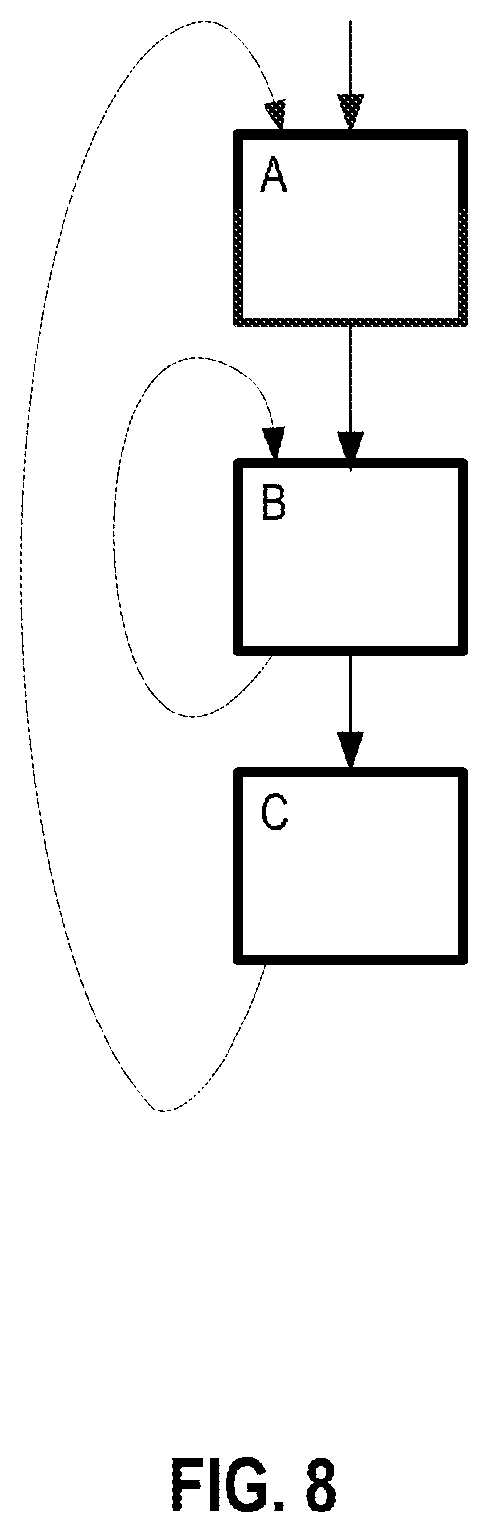
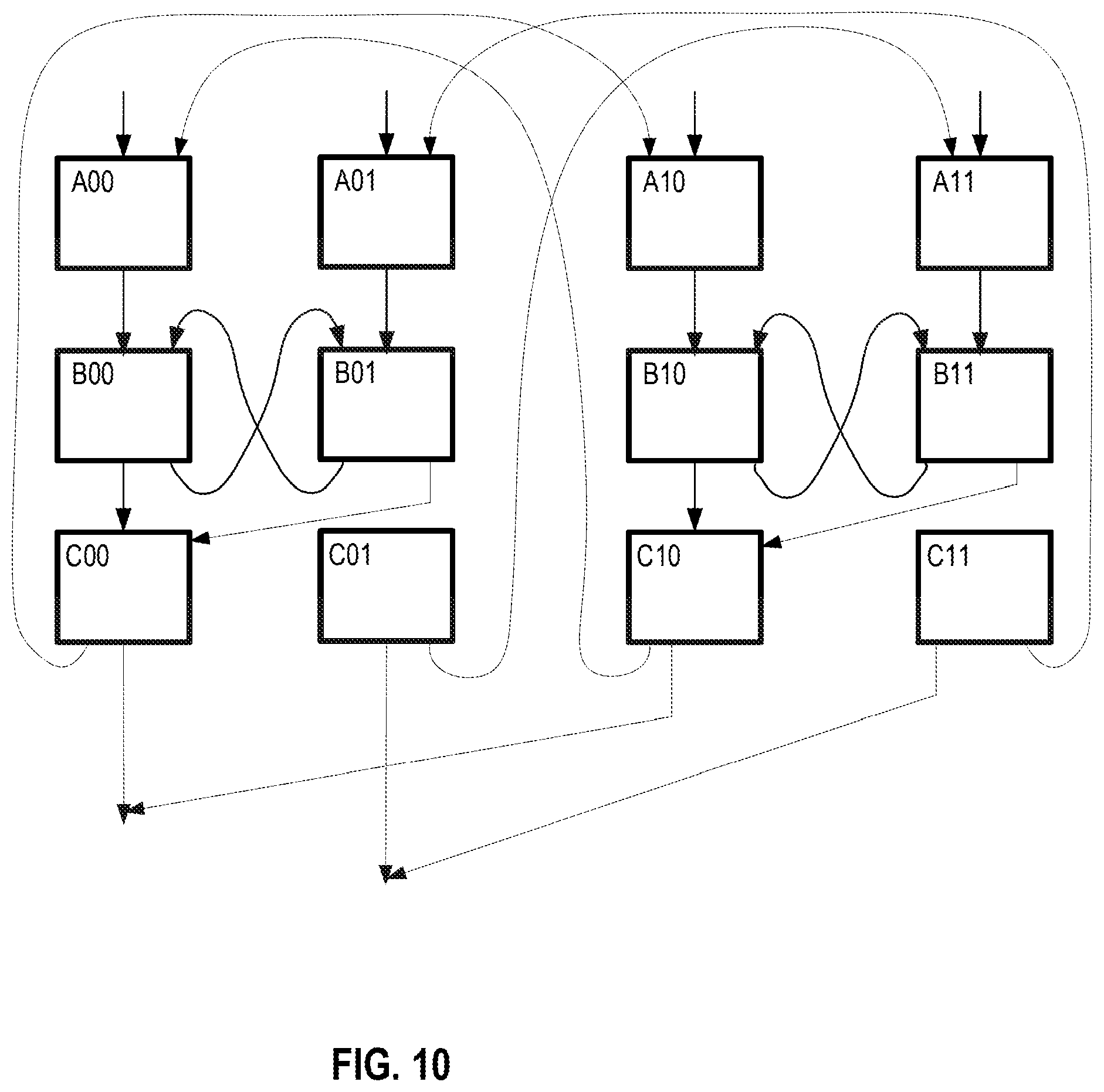
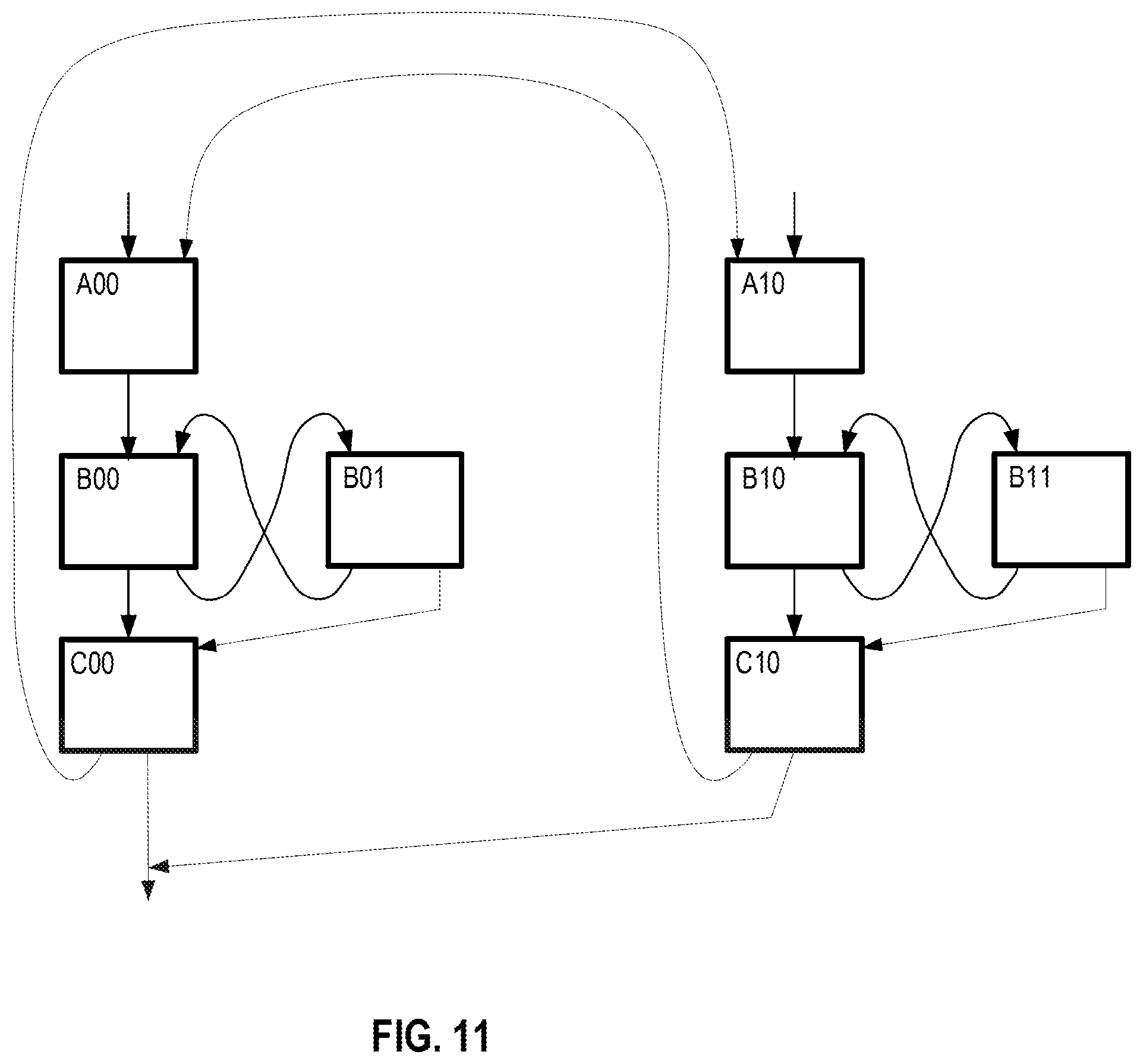
FIGS. 8-11 illustrate examples of some of software operations.
FIG. 12 is a block diagram illustrating an exemplary out-of-order architecture of a core according to embodiments of the invention.
FIG. 13 shows a block diagram of a system in accordance with one embodiment of the present invention.
FIG. 14 shows a block diagram of a second system in accordance with an embodiment of the present invention.
FIG. 15 shows a block diagram of a third system in accordance with an embodiment of the present invention.
DETAILED DESCRIPTION
In the following description, numerous specific details are set forth. However, it is understood that embodiments of the invention may be practiced without these specific details. In other instances, well-known circuits, structures and techniques have not been shown in detail in order not to obscure the understanding of this description.
References in the specification to "one embodiment," "an embodiment," "an example embodiment," etc., indicate that the embodiment described may include a particular feature, structure, or characteristic, but every embodiment may not necessarily include the particular feature, structure, or characteristic. Moreover, such phrases are not necessarily referring to the same embodiment. Further, when a particular feature, structure, or characteristic is described in connection with an embodiment, it is submitted that it is within the knowledge of one skilled in the art to affect such feature, structure, or characteristic in connection with other embodiments whether or not explicitly described.
Embodiments of systems, apparatuses, and methods for providing dynamic thread switch execution are detailed below. Embodiments of systems that support this consist of processor cores surrounded by a hardware wrapper and software (dynamic thread switch software). In a normal execution mode, the processor operates as if the hardware wrapper and dynamic thread switch software does not exist. For example, normal x86 execution occurs. In the dynamic thread switch execution (DTSE) mode, the hardware wrapper and software work together to perform dynamic thread switch execution including the generation and modification of flows, etc. as will be detailed below. However, a high-level overview is first provided. A more detailed explanation of some of these topics such as "flows" and "hot" code follows.
The details below describe a combination of a hardware wrapper that checks that each load gets data from the correct stores and certain other things before globally committing, together with software that uses recent observed code behavior to resolve code dependencies that are difficult to determine from the code alone, the because hardware will check and guarantee correct execution.
The details below describe the identification of many static instances in original code such that dependencies are understood between specific instances of original instructions and not between the original instructions themselves.
The described software uses a complete, but likely not perfectly correct, understanding of dependencies within a defined static code subset called a "Flow," to separate static code into separate "Tracks" that have no dependencies (or only specifically allowed dependencies) between tracks, within that flow.
Additionally, maintenance operations including one or more of the following: taking additional profiles of flows that get shorter than desired dynamic execution before exiting due to unexpected control flow or incorrect load results or failure of other checks; deletion of flows that suddenly become bad in this respect; continual search for new or replacement flows significant to performance; and re-separation of the code into tracks when there is new profile information and deletion of flows that are observed to not perform better than the original code are described.
DTSE Hardware will form a sequential list and write these to the Mid Level Cache. DTSE hardware has registers with the physical addresses associated with this Track's Metadata list. We may have to consider compression of the load and store addresses to keep bandwidth down.
We will need to be able to track the Logical Processor that is executing a load or store, to Load execution and to senior store processing.
DTSE logic also gets branch direction bits at retirement and the targets of taken indirect branches, including returns. This is used for Flash Profiling and for data to support register state recovery.
I. High-Level Overview
As detailed above, the processor detailed herein may operate in a legacy mode where each core operates one its own. The processor cores may also be used for profiling, threading, and running threaded code in DTSE mode when one of the cores is "off" or halted. The halt flow switches ownership of the core from the OS to DTSE mode although the operating system assumes that the core is in a sleep mode.
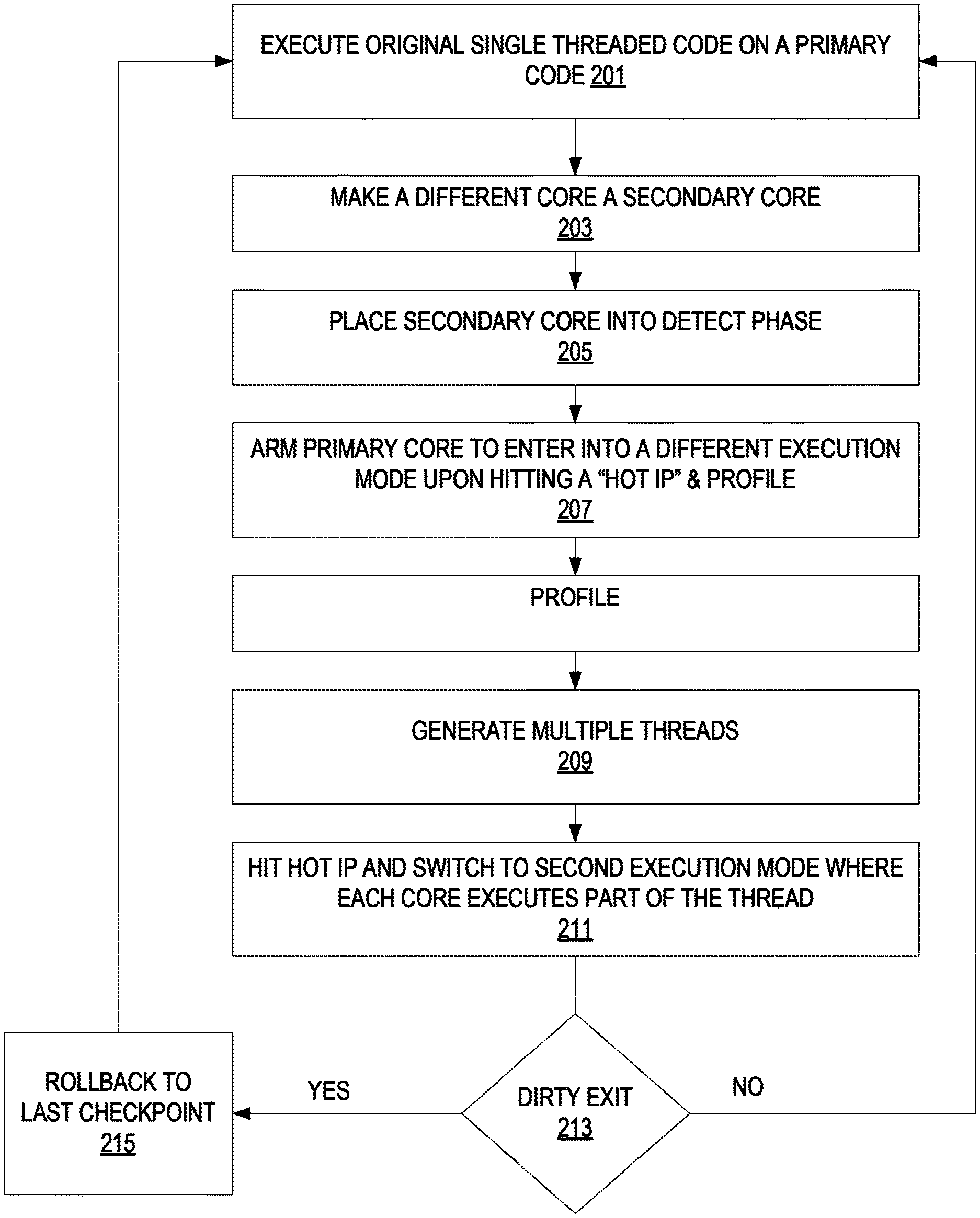
FIG. 1 graphically illustrates an exemplary embodiment of DTSE operation. This begins taking control of an idle core which becomes the secondary core in the illustration. In some embodiments, control of the idle core occurs when core receives a HALT/WMAIT instruction. The DTSE software watches for all threads of the core to be put to sleep and then assumes control of the core.
The secondary code starts by detecting "hot-code" which is an entry point the software running on the primary core which corresponds to a large part of the dynamic execution (e.g., a kernel that runs for 100K consecutive instructions). Hot-code detection is typically done in a simple hardware structure. Once a hot entry point has been detected, it is armed for profiling. Once hit (by the primary core), the hot-code goes into profiling mode which means that all loads, stores, and branches are profiled for some set amount of instructions (such as 50,000 instructions). Once profiling is finished, thread generation is performed. Thread generation analyzes the hot-code and based on the profiled information generates two threads for the threaded execution mode. Once completed, the entry point (hot IP) is armed as a DTSE mode entry point. The next time the original code (running on the primary core) hits the entry point, it switches into DTSE mode in which both cores cooperative execute the code. DTSE mode ends if the flow exits the hot-code or if a violation or external event (e.g., interrupt) is detected. Violations include, for example, when both cores store different data to the same memory address in the same epoch. Upon violation, the threaded mode rolls back to the last commit point and moves back to the original code.
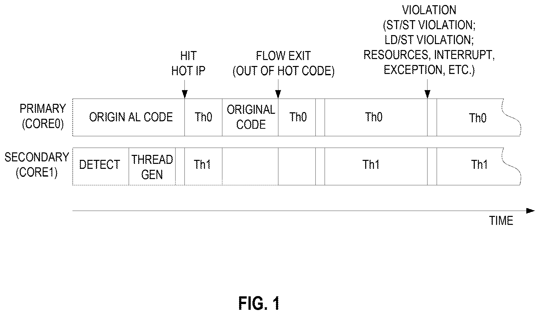
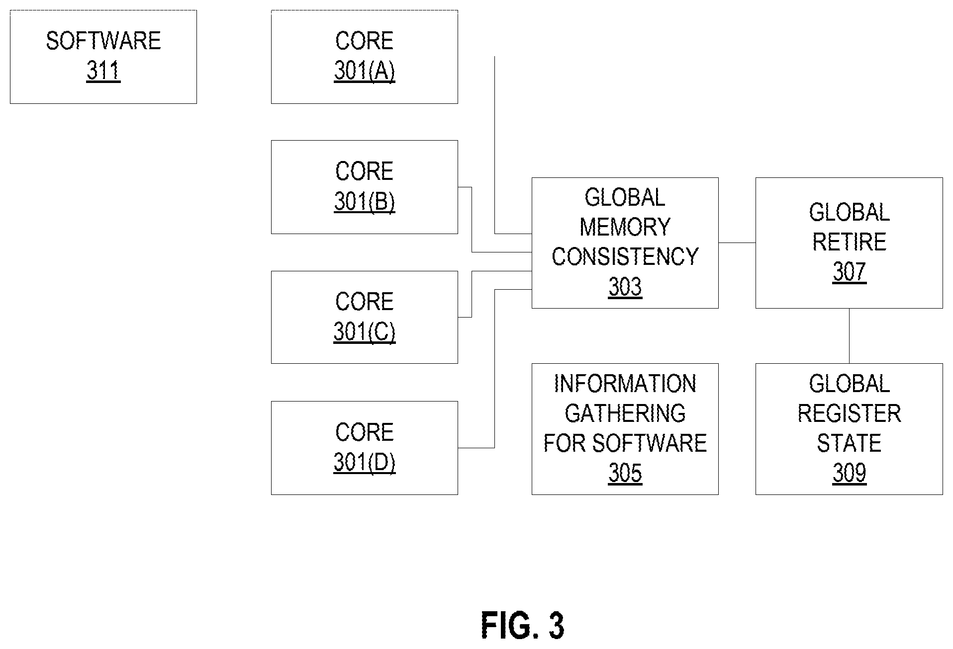
FIG. 2 illustrates an exemplary method of the DTSE operation according to some embodiments. In this example two cores are utilized to process threaded code. The primary core (core 0) executes the original single threaded code at 201.
At 203, another core (core 1) is turned into and used as a secondary core. A core can be turned into a secondary core (a worker thread) in many ways. For example, a secondary core could be used as a secondary core as a result of static partitioning of the cores, through the use of hardware dynamic schemes such as grabbing cores that are put to sleep by the OS (e.g., put into a C-State), by software assignment, or by threads (by the OS/driver or the application itself).
While the primary core is executing the original code, the secondary core will be placed into a detect phase at 205, in which it waits for a hot-code detection (by hardware or software) of a hot-region. In some embodiments, the hot-code detection is a hardware table which detects frequently accessed hot-regions, and provides its entry IP (instruction pointer). Once such a hot-region entry IP is detected, the primary core is armed such that it will trigger profiling on the next invocation of that IP and will switch execution to a threaded version of the original code at 207. The profiling gathers information such as load addresses, store addresses and branches for a predetermined length of execution (e.g. 50,000 dynamic instructions).
Once profiling has finished, the secondary core starts the thread-generation phase (thread-gen) 209. In this phase, the secondary core generates the threaded version of the profiled region, while using the profiled information as guidance. The thread generation provides a threaded version of the original code, along with possible entry points. When one of the entry points (labeled as a "Hot IP") is hit at 211, the primary core and the secondary cores are redirected to execute the threaded version of the code and execution switches into a different execution mode (sometimes called the "threaded execution mode"). In this mode, the two threads operate in complete separation, while the wrapper hardware is used to buffer memory loads and store, check them for possible violations, and atomically commit the state to provide forward progress while maintaining memory ordering.
This execution mode may end one of two ways. It may end when the code exits the hot-region as clean-exit (no problems with the execution) or when a violation occurs as a dirty-exit. A determination of which type of exit is made at 213. Exemplary dirty exits are store/store and load/store violations or an exception scenario not dealt with in the second execution mode (e.g., floating point divide by zero exception, uncacheable memory type store, etc.). On exit of the second execution mode, the primary core goes back to the original code, while the secondary core goes back to detection mode, waiting for another hot IP to be detected or an already generated region's hot IP to be hit. On clean exit (exit of the hot-region), the original code continues from the exit point. On dirty-exit (e.g., violation or exception), the primary core goes back to the last checkpoint at 215 and continues execution for there. On both clean and dirty exits, the register state is merged from both cores and moved into the original core.
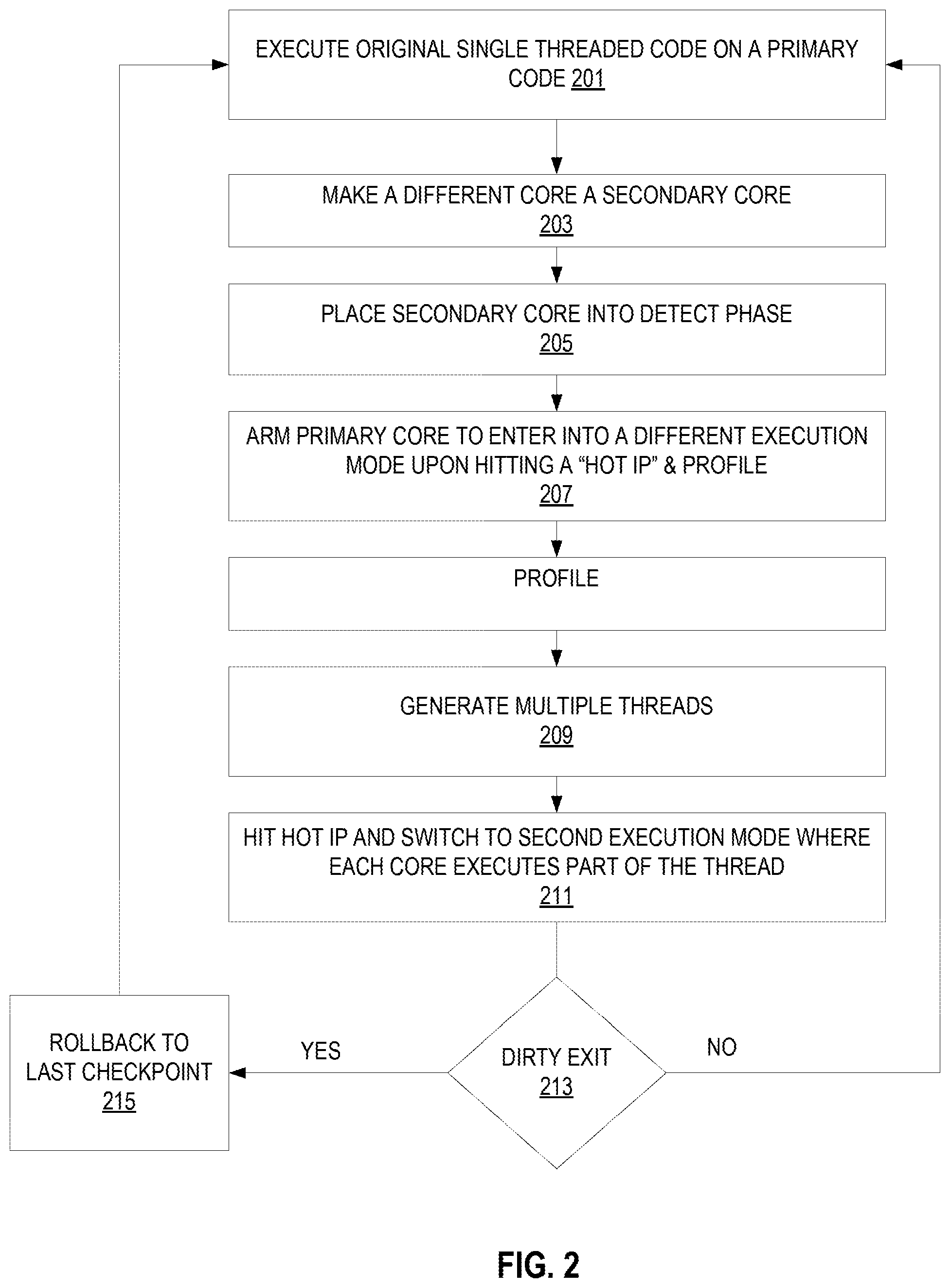
Exemplary DTSE Architecture
FIG. 3 illustrates an embodiment of a dynamic thread switch execution architecture. The software and hardware aspects of this system are discussed below in detail. As discussed above, each core 301 may natively support Simultaneous Multi-Threading (SMT). This means that two or more logical processors may share the hardware of the core. Each logical processor independently processes a code stream, yet the instructions from these code streams are randomly mixed for execution on the same hardware. Frequently, instructions from different logical processors are executing simultaneously on the super scalar hardware of a core. The performance of SMT cores and the number of logical processors on the same core is increased. Because of this, some important workloads will be processed faster because of the increased number of logical processors. Other workloads may not be processed faster because of an increased number of logical processors alone.
There are times when there are not enough software threads in the system to take advantage of all of the logical processors. This system automatically decomposes some or all of the available software threads, each into multiple threads to be executed concurrently (dynamic thread switch from a single thread to multiple threads), taking advantage of the multiple, perhaps many, logically processors. A workload that is not processed faster because of an increased number of logical processors alone is likely to be processed faster when its threads have been decomposed into a larger number of threads to use more logical processors.
In additional to the "traditional" cores, the hardware includes dynamic thread switch logic that includes logic for maintaining global memory consistency 303, global retirement 307, global register state 309, and gathering information for the software 305. This logic may be included in the cores themselves or be provided separately. This logic may perform five functions. The first is to gather specialized information about the running code which is called profiling. The second, is while original code is running, the hardware must see execution hitting hot IP stream addresses that the software has defined. When this happens, the hardware forces the core to jump to different addresses that the software has defined. This is how the threaded version of the code gets executed. The third is the hardware must work together with the software to effectively save the correct register state of the original code stream from time to time as Global Commit Points inside of a core's data cache. If the original code stream was decomposed into multiple threads by the software, then there may be no logical processor that ever has the entire correct register state of the original program. The correct memory state that goes with each Global Commit Point should also be known. When necessary, the hardware, working with the software must be able to restore the architectural program state, both registers and memory, to the Last Globally Committed Point as will be discussed below. Fourth, although the software will do quite well at producing code that executes correctly, there are some things the software cannot get right 100% of the time. A good example is that the software, when generating a threaded version of the code, cannot anticipate memory addresses perfectly. So the threaded code will occasionally get the wrong result for a load. The hardware must check everything that could possibly be incorrect. If something is not correct, hardware must work with the software to get the program state fixed. This is usually done by restoring the core state to the Last Globally Committed State. Finally, if the original code stream was decomposed into multiple threads, then the stores to memory specified in the original code will be distributed among multiple logical processors and executed in random order between these logical processors. The dynamic tread switch logic must ensure that any other code stream will not be able to "see" a state in memory that is incorrect, as defined by the original code, correctly executed.
In these exemplary architecture, a processor core ("core") usually has two SMT threads. In general, in the DTSE mode there are many more than 2 "Logical Processors" per core. These logical processors are defined as being one of two types: "Primary" and "Worker." A Primary Logical Processor is known to software, i.e., the operating system and Virtual Machine Monitor. The software sees the set of Primary Logical Processors on a core as SMT threads on the core that they are actually on. Primary Logical Processors to do most, if not, everything that an SMT thread does, and in particular, get interrupts.
Worker Logical Processors are not generally visible to external software. They are used by and managed by DTSE software in "reserved memory." This memory is a physically addressable, reserved memory system. This reserved memory could either be a dedicated portion of existing system memory or separate physical memory. This reserved memory is used to store DTSE code and act as its working memory. Data structures generated in the DTSE mode are store in the reserved memory. The "hot" code is also stored in this reserved memory. Track data, the track data directory, and track metadata are in reserved memory. All of these things are addressed physically.
Worker Logical Processors do not have the full context that a Primary Logical Processor has, and, as a result, they are restricted to a subset of the full processor functionality. Worker Logical Processors execute only code in a flow in reserved memory and will not execute original code in visible memory.
A Primary Logical Processor may execute original code in visible memory or code in a flow in hidden memory. The code in a flow in hidden memory that a Primary would execute is single Track code, from a DTSE perspective.
In operation, the operating system runs threads on Primary Logical Processors, as it does today. The Primary Logical Processors are all the same and are grouped into "cores." There are many Primary Logical Processors and each one is very high performance. The performance of a Primary Logical Processor multiplied by the number of Primary Logical Processors available to the operating system far exceeds the throughput capability of the chip.
It is possible to use the entire capability of the chip using a fraction of the Primary Logical Processors that are provided. On the other hand, well coded, massively parallel programs may use the capability of the chip more efficiently, and therefore achieve higher performance, by using a large number, preferably all, of the provided Primary Logical Processors.
If the running Primary Logical Processors are not using all the resources that the chip has to offer, then DTSE software will do automatic thread decomposition. It will run parallelized compute flows on Worker Logical Processors. This includes, especially, decomposition of significant SSE and AVX code to run on the through put engine in parallel. This includes running code that can run on special function units on those special function units.
Basically, when the thread on a Primary Logical Processor is actually running a compute flow on Worker Logical Processors, the Primary Logical Processor has nothing to do. It is effectively halted while the operating system thinks it is doing all the work. As detailed above, the operating system does not know about the Worker Logical Processors. When a compute flow is running on Workers, the Primary Logical Processor that owns it is waiting for one of two things to happen: an interrupt or a flow exit in the compute flow. If either of those things happens, the Primary takes over. If there is an interrupt that goes to an Interrupt Flow, it immediately executes that Interrupt Flow, in parallel with its Compute Flow on the Workers. In most cases the Interrupt Flow does the entire interrupt handling and the Primary is back to waiting, without any impact on the Compute Flow at all. When there is a Flow exit in its Compute Flow, the waiting Primary constructs the register state at that point, and resumes in original code. Ideally, it will hit a hot code entry point very soon. This will begin execution of a new Compute Flow, or possibly a System Flow on the Primary Logical Processor.
The DTSE software 311 includes may include routines for generating, maintaining, and removing flows among other tasks detailed below.
Hardware "Wrapper"
In some embodiments, a hardware wrapper is used for dynamic thread switch execution logic. The wrapper hardware supports one or more of the following functionalities: 1) detecting hot regions (hot code root detection); 2) generating information that will characterize to hot region (profile); 3) buffering state when executing transactions; 4) commit the buffered state in case of success; 5) discarding the buffered state in case of abort; 6) detecting coherency events, such as write-write and read-write conflict; 7) guarding against cross modifying code; and/or 7) guarding against paging related changes. Each of these functionalities will be discussed in detail below or has already been discussed.
While in DTSE execution mode, the generated threads operate together, but have no way of communicating. Each core executes its own thread, while commit/span markers denote IPs in the threaded-code that correspond to some IP in the original code. The DTSE hardware buffers loads and stores information, preventing any store to be externally visible (globally committed). When both cores have reached a span marker the loads and stores are checked for violations. If no violations were detected, the stores can become globally committed. The commit of stores denotes a checkpoint to which execution should jump in case of a violation/dirty exit.
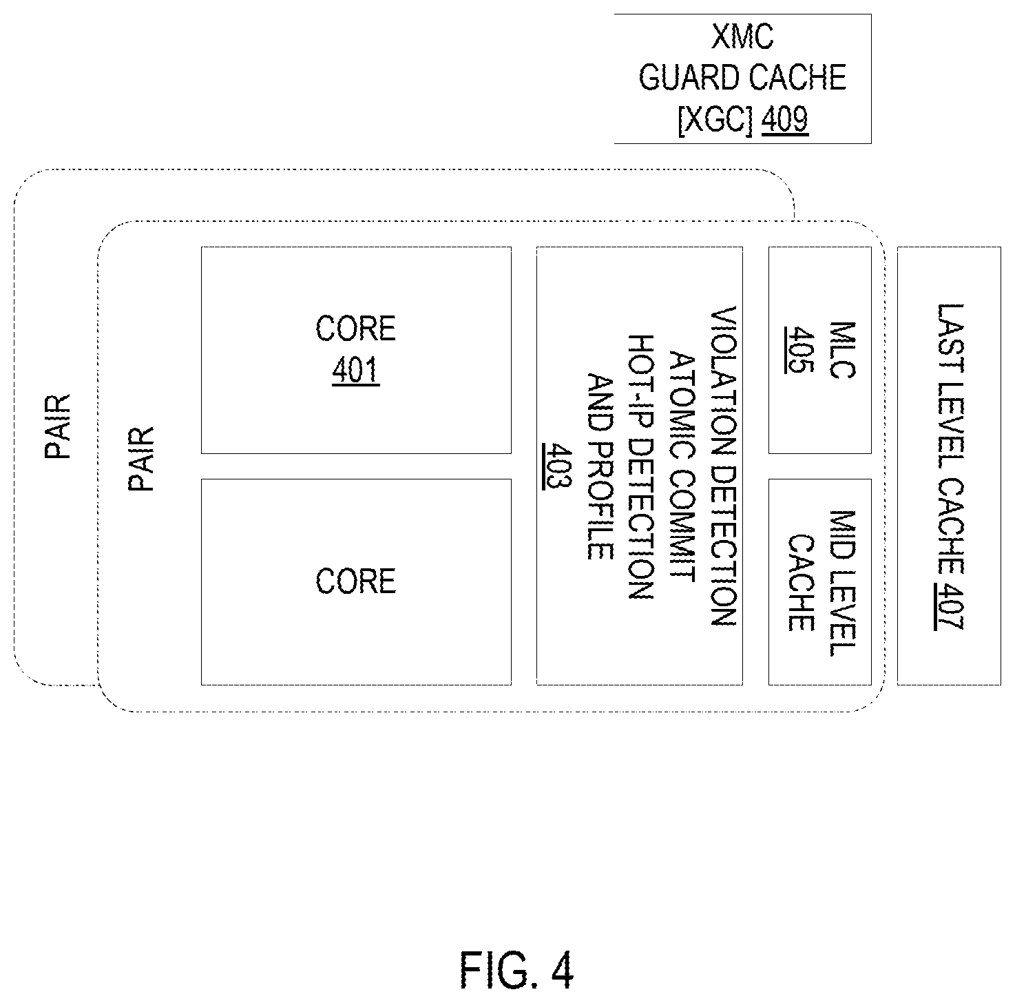
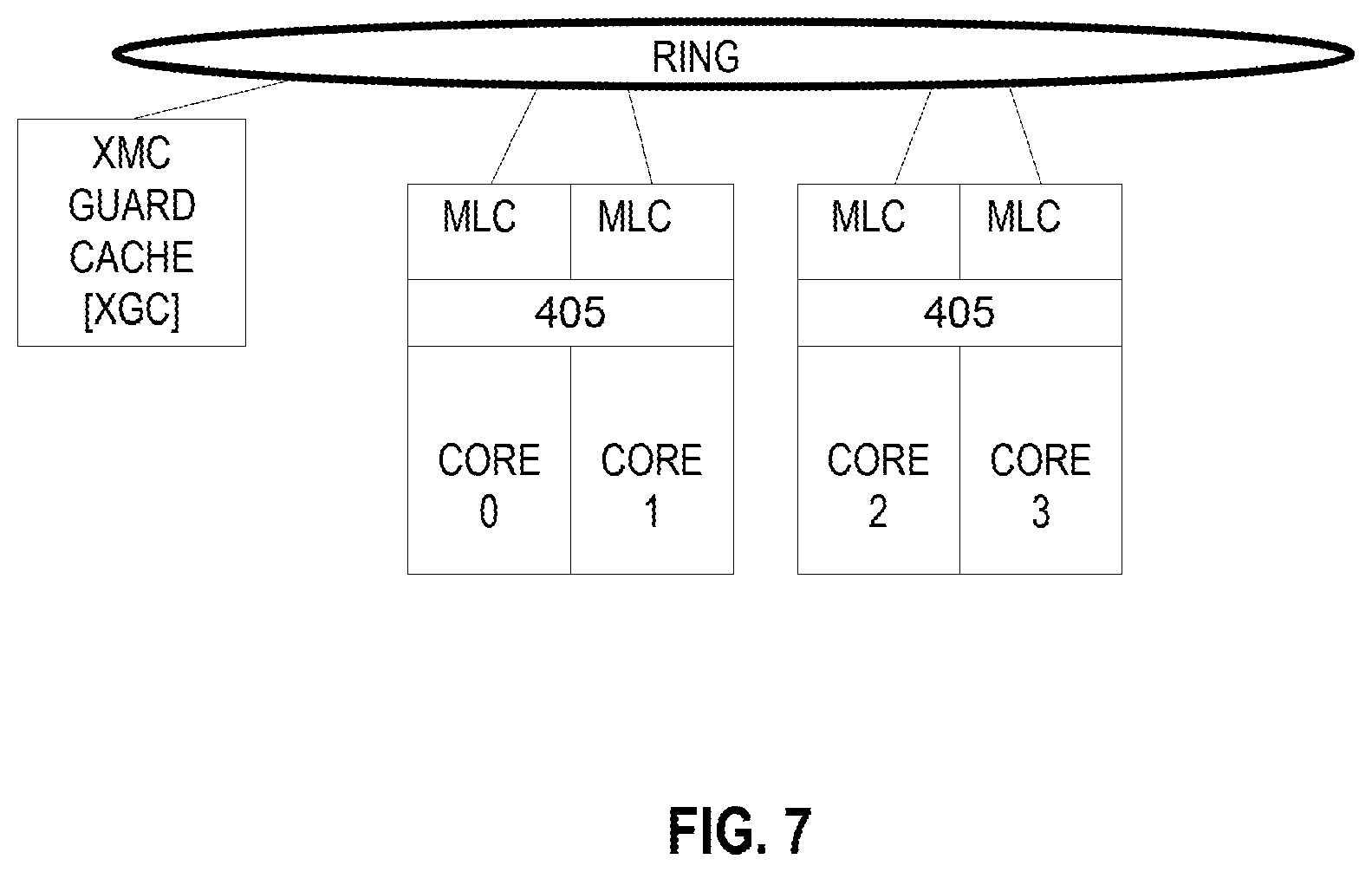
FIG. 4 illustrates the main hardware blocks for the wrapper according to some embodiments. As discussed above, this consists of two or more cores 401 (shown as a belonging to a pair, but there could be more). Violation detection, atomic commit, hot IP detection, and profiling logic 403 is coupled to the cores 401. In some embodiments, this group is called the dynamic thread switch execution hardware logic. Also coupled to the cores is mid-level cache 405 where the execution state of the second execution mode is merged. Additionally, there is a last level cache 407. Finally, there is a xMC guardata cache (XGC 409) which will be discussed in detail with respect to FIG. 7.
A number of "flows" for an application will be identified by the hardware in root detection hardware (not explicitly illustrated). Each flow is a well-defined set of binary code with one or more entry points. The set of flows for the application should cover a significant amount of the dynamic execution of the application, but the combined size of the static flows should be small due to parallelization of the flows.
When original code is being executed, the root detection hardware searches for a single IP value, called the "root" that will identify a new flow. Typically, this hardware will not search while execution is in a flow. In some embodiments, the hardware will keep a list of 64 instruction pointers (IPs). The list is ordered from location 0 to location 63, and each location can have an IP or be empty. The list starts out all empty.
If there is an eligible branch to an IP that matches an entry in the list at location N, then locations N-1 and N swap locations, unless N=0. If N=0, then nothing happens. More simply, this IP is moved up one place in the list.
If there is an eligible branch to an IP that does NOT match an entry in the list, then entries 40 to 62 are shifted down 1, to locations 41 to 63. The previous contents of location 63 are lost. The new IP is entered at location 40.
In some embodiments, there are restrictions on which IPs are "eligible" to be added to the list, or be "eligible" to match, and hence cause to be promoted, an IP already on the list. The first such restriction is that only targets of taken backward branches are eligible. Calls and returns are not eligible. If the taken backward branch is executing "hot" as part of a flow and it is not leaving the flow, then its target is not eligible. If the target of the taken backward branch hits in the hot code entry point cache, it is not eligible. Basically, IPs that are already in flows should not be placed in to the list.
In some embodiments, there are two "exclude" regions that software can set. Each region is described by a lower bound and an upper bound on the IP for the exclude region. Notice that this facility can be set to accept only IPs in a certain region. The second restriction is that IPs in an exclude region are not eligible to go in the list.
In some embodiments, no instruction that is less than 16,384 dynamic instructions after hitting an instruction in the list is eligible to be added, however, it is permissible to replace the last IP hit in the list with a new IP within the 16,384 dynamic instruction window. Basically, a flow is targeted to average a minimum of 50,000 instructions dynamically. An IP in the list is a potential root for such a flow. Hence the next 16,000 dynamic instructions are considered to be part of the flow that is already represented in the list.
In some embodiments, the hardware keeps a stack 16 deep. A call increments the stack pointer circularly and a return decrements the stack pointer, but it does not wrap. That is, on call, the stack pointer is always incremented. But there is a push depth counter. It cannot exceed 16. A return does not decrement the stack pointer and the push depth counter if it would make the push depth go negative. Every instruction increments all locations in the stack. On a push, the new top of stack is cleared. The stack locations saturate at a maximum count of 64K. Thus, another restriction is that no IP is eligible to be added to the list unless the top of stack is saturated. The reason for this is to avoid false loops. Suppose there is a procedure that contains a loop that is always iterated twice. The procedure is called from all over the code. Then the backward branch in this procedure is hit often. While this looks very hot, it is logically unrelated work from all over the place, and will not lead to a good flow. IPs in the procedures that call this one are what is desired. Outer procedures are preferred, not the inner ones, unless the inner procedure is big enough to contain a flow.
In some embodiments, if an IP, I, is either added to the list, or promoted (due to hitting a match), then no instruction within the next 1024 dynamic instructions is eligible to match I. The purpose of this rule is to prevent overvaluing tight loops. The backward branch in such loops is hit a lot, but each hit does not represent much work.
The top IPs in the list are considered to represent very active code.
The typical workload will have a number of flows to get high dynamic coverage. It is not critical that these be found absolutely in the order of importance, although it is preferable to generally produce these flows roughly in the order of importance in order to get the biggest performance gain early. A reasonable place for building a flow should be found. This will become hot code, and then it is out of play for finding the next flow to work on. Most likely, a number of flows will be found.
The flows, in general, are not disjoint and may overlap. But, at least the root of each flow is not in a previously found flow. It may actually still be in a flow that is found later. This is enough to guarantee that no two flows are identical. While specific numbers have been used above, these are merely illustrative.
There are at least two kinds of flows for this architecture: system slows and compute flows. Compute Flows execute on a cluster of Worker Logical Processors. A System Flow executes on a Primary Logical Processor.
A Compute Flow may be, but is not required to be, multiple Tracks made from a single code stream by thread decomposition. A Compute Flow is executed entirely by Worker Logical Processors within a single Cluster because the whole Flow must be Globally committed in Program order after being checked (but typically is Globally committed as a sequence of Commit Spans, not in a single piece). All of the Workers executing the Flow can freely load and store to the same addresses. A Compute Flow is the most restrictive in terms of what it cannot do.
A System Flow is also code produced by DTSE software and also resides in hidden memory. There are numerous things that cannot be done in a System Flow. It is restricted, but much less restricted than a Compute Flow. A System Flow is either serial code between Compute Flows or an independent parallel thread to Compute Flows.
One of the most important uses for a System Flow is interrupt processing. At times, DTSE software creates Flows whose entry points are the most popular interrupt vector targets. This code will cover the most popular paths from these vector targets. If an interrupt can be completely handled within a System Flow, from vector target to the interrupt return (IRET) back to the interrupted code without a System Flow exit, then there is no need to disturb the Workers executing the Flow that was "interrupted". If the entire interrupt handling sequence cannot be so handled, then a Flow exit must be forced in the Workers executing the Flow that was "interrupted." A context switch will always cause an Interrupt Flow exit, and hence a Flow exit in the "interrupted" Compute Flow.
If the interrupt can be handled in this Interrupt Flow, then registers are never saved. The Interrupt System Flow is a single Global Commit Span. Either it will finish to the IRET and all commit as a unit, or the state will be recovered to the target of the interrupt vector and execution resumes from there in the original code. The state recovery includes stopping Global Commitment (and further execution) in the Compute Flow, and recovering register state from the last Global Commit Point in the Compute Flow.
Code in Flows in Hidden Memory can be thread switched ultra fast and efficiently, because the thread switching is programmed right into the code. Original code cannot have the thread switching programmed in. Thread switching involving original code is slow and inefficient.
Compute Flows are restricted as to what they can do. Some original code is not eligible to go into Compute Flows. Some code that is ineligible for Compute Flows can go into System Flows which are less restrictive. Then there is still some code that is not eligible even to go into System Flows. This must remain original code.
In some embodiments, including unlimited amounts of original code, if need be, are multiplexed with flows of both types.
Once a hot-code root IP (entry IP) is detected, the primary core is armed so that on the next hit of that IP, the core will start profiling the original code. While profiling, the information above (branches, loads and stores) are stored in program dynamic order into buffers in memory. These buffers are later used by the thread generation software to direct the thread generation--eliminate unused code (based on branches), direct the optimizations, and detect load/store relationships. In some embodiments, the same hardware used for conflicts checking (will be described later) is used to buffer the loads, stores and branch information from retirement, and spill it into memory. In other embodiments, micro-operations are inserted into the program at execution which would store the required information directly into memory.
To characterize a hot region (profiling), the threaded execution mode software requires one or more of the following information: 1) for branches, it requires a) for conditional branches taken/not taken information, and b) for indirect branches the branch target; 2) for loads, a) a load address and b) access size; and 3) for stores a) a store address and b) a store size.
In some embodiments, an ordering buffer (OB) will be maintained for profiling. This is because loads, stores and branches execute out-of-order, but the profiling data is needed in order. The OB is similar in size to a Reordering Buffer (ROB). Loads, while dispatching, will write their address and size into the OB. Stores, during the STA (store address) dispatch, will do the same (STA dispatch is prior to the store retirement the purpose of this dispatch is to translate the virtual store address to physical address). Branches will write the `to` field, that can be used for both direct and indirect branches. When these loads, stores and branches retire from the ROB, their corresponding information will be copied from the OB. Hot code profiling uses the fact that the wrapper hardware can buffer transactional state and later commit it. It will use the same datapath of committing buffered state to copy data from the OB to a Write Combining Cache (will be described later), and then commit it. The profiling information will be written to a dedicated buffer in a special memory location to be used later by threaded execution software.
In some embodiments, the DTSE software writes an IP in a register and arms it. The hardware will take profile data and write it to a buffer in memory upon hitting this IP. The branch direction history for some number of branches (e.g., 10,000) encountered after the flow root IP is reported by the hardware during execution. The list is one bit per branch in local retirement order. The dynamic thread switch execution software gets the targets of taken branches at retirement. It reports the targets of indirect branches embedded in the stream of branch directions. At the same time, the hardware will report addresses and sizes of loads and stores.
As applications may change their behavior over time, the execution should be monitored for as long as the application executes. As flows appear to become "too" short, they should be grown or deleted. Additionally, new flows can be found, regenerated, and merged at any given time. In some embodiments, the dynamic thread switch execution system's hardware will report average globally committed instructions and cycles for each flow. The software will need to consider this and also occasionally get data on original code, by temporarily disabling a flow, if there is any question. In most instances, the software does not run "hot" code unless it is pretty clear that it is a net win. If it is not clear that "hot" code is a net win, the software should disable it. This can be done flow by flow, or the software can just turn the whole thing off for this workload.
The software will continue to receive branch miss-prediction data and branch direction data. Additionally, the software will get reports on thread stall because of its section of the global queue being full, or waiting for flow capping. These can be indicative of an under loaded track (discussed later) that is running too far ahead. It will also get core stall time for cache misses. For example, Core A getting a lot of cache miss stall time can explain why core B is running far ahead. All of this can be used to do better load balancing of the tracks for this flow. The hardware will also report the full identification of the loads that have the highest cache miss rate. This can help the software redistribute the cache misses.
In some embodiments, the software will get reports of the cycles or instructions in each flow execution. This will identify flows that are too small, and therefore have excessive capping overhead.
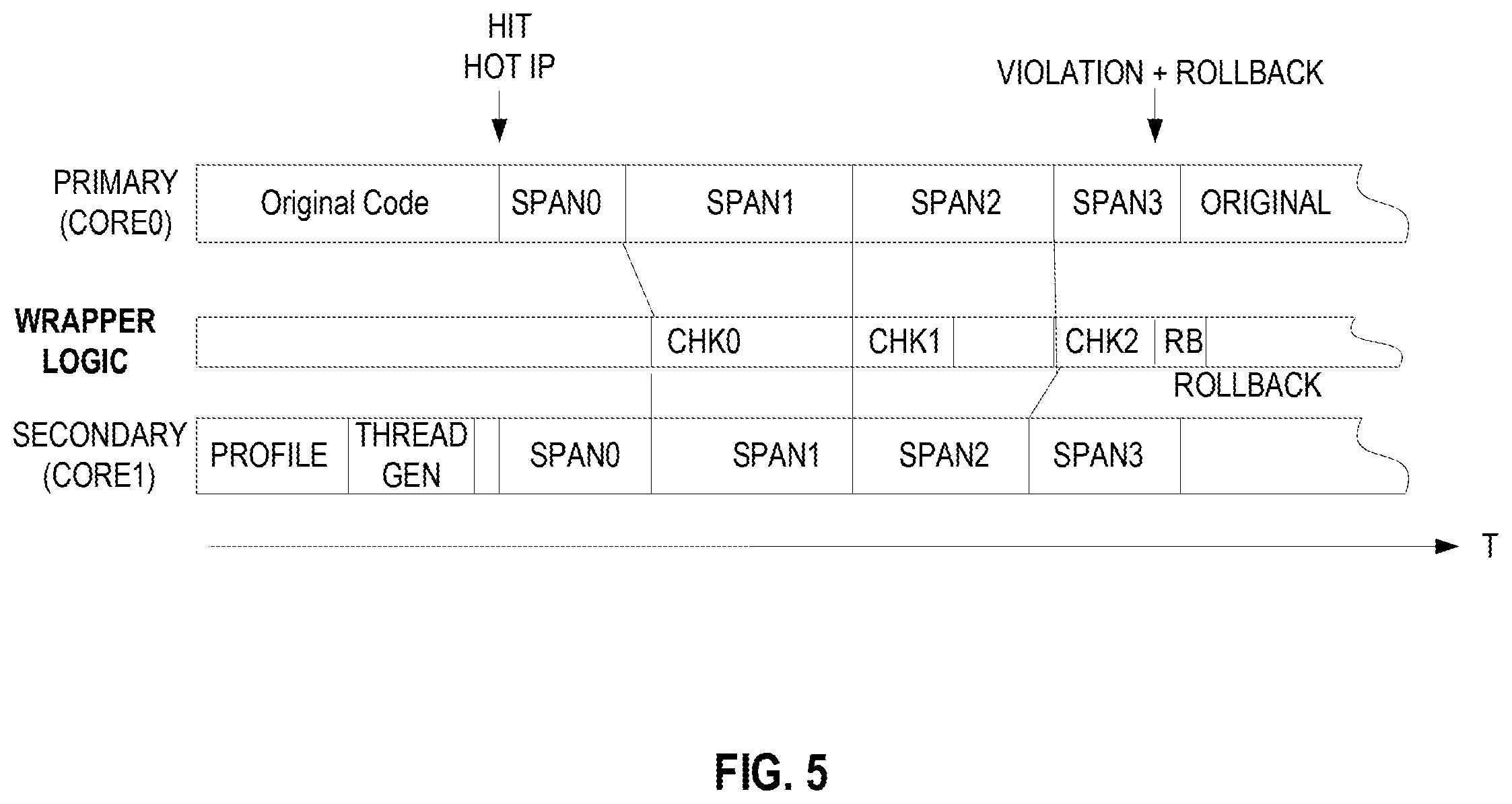
FIG. 5 illustrates spanned execution according to an embodiment. When the threaded execution software generates threads for hot code it tries to do so with as little duplication as possible. From the original static code, two or more threads are created. These threads are spanned. Span marker syncs are generated to the original code and violations (such as those described above) are checked at the span marker boundaries. The memory state may be committed upon the completion of each span. As illustrated, upon hitting a hot IP, the execution mode is switched to threaded execution. What is different from the previous general illustration is that each thread has spans. After each span a check (chk) is made. In the example, after the second span has executed the check (chk2) has found a violation. Because of this violation the code is rolled back to the last checkpoint (which may be after a thread or be before the hot IP was hit).
As discussed above, threaded execution mode will exit when the hot code region is exited (clean exit) or on violation condition (dirty exit). On a clean exit, the exit point will denote a span and commit point, in order to commit all stores. In both clean and dirty exits, the original code will go to the corresponding original IP of the last checkpoint (commit). The register state will have to be merged from the state of both cores. For this, the thread generator will have to update register checkpoint information on each commit. This can be done, for example, by inserting special stores that will store the relevant registers from each core into a hardware buffer or memory. On exit, the register state will be merged from both cores into the original (primary) core. It should be noted that other alternatives exist for registers merging, for example register state may be retrievable from the buffered load and store information (as determined by the thread generator at generation time).
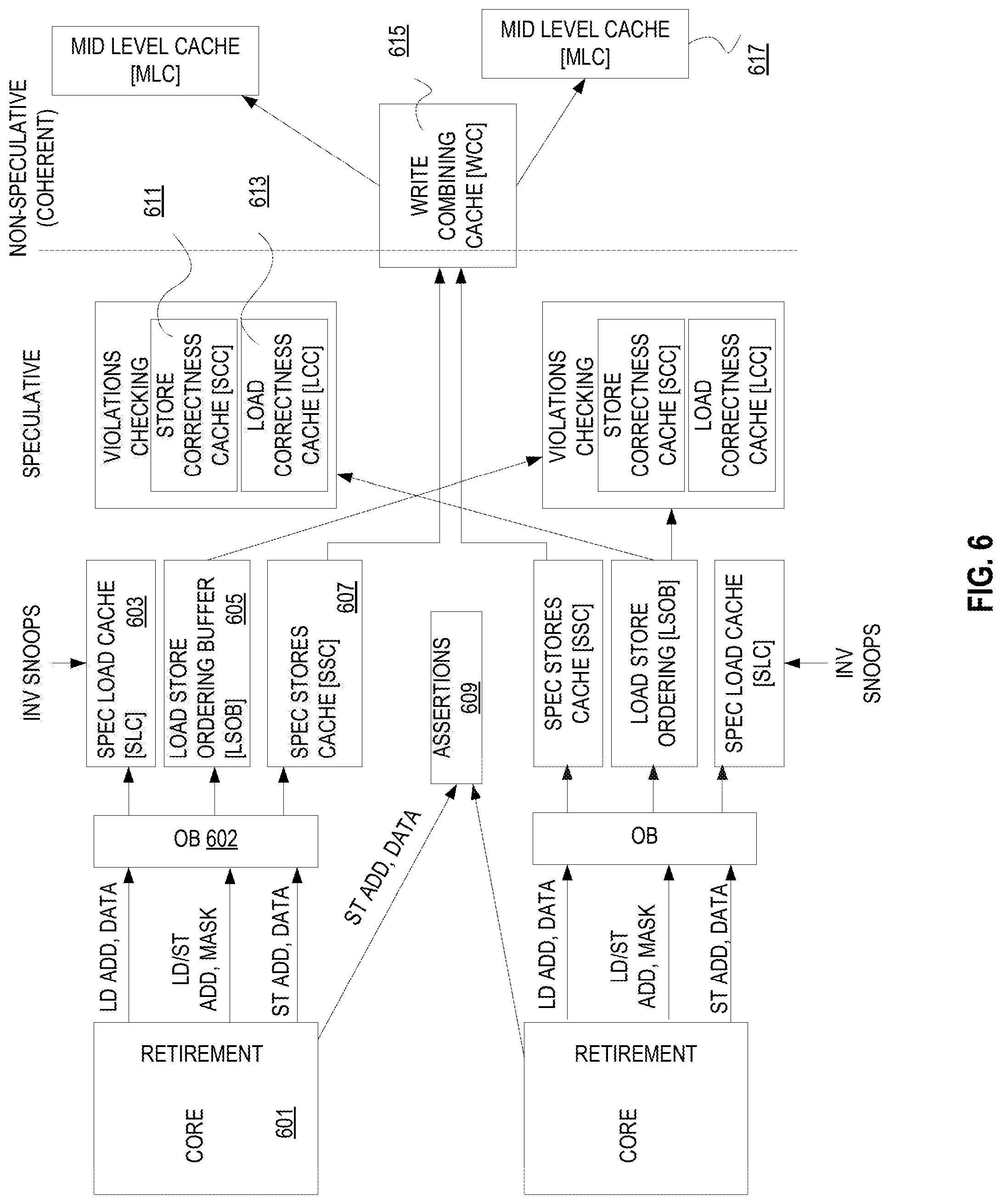
A more detailed illustration of an embodiment of DTSE hardware is illustrated in FIG. 6. This depicts both speculative execution on the left and coherent on the right. In some embodiments, everything but the MLC 617 and cores 601 forms a part of the violation detection, atomic commit, hot IP detection, and profiling logic 403. The execution is speculative because while in the threaded mode the generated threads in the cores 601 operate together, they do not communicate with each other.
In some embodiments, the hardware wrapper includes a single physical protection cache that protects original code for which there is a copy, in some form, in reserved memory (again, this is not illustrated). In some embodiments, this is a 16 K line, 8 way set associative cache where each line covers 4096 Bytes of original code. The resolution is to 64 Byte blocks. The cache line contains a starting block and ending block within the 4096 Byte aligned scope of the line. A block number is 6 bits. This cache may have multiple lines in the same set with the same tag. Hence, when reading the physical protection cache, multiple lines in the same set may be hit up to 8 lines. This provides the capability to represent several disjoint spans in the same 4096 Bytes, with unprotected gaps in between.
Software 311 should ensure that no 64 Byte block is represented in the Physical Protection Cache more than once. When a check for a hit on a 64 Byte block is made, a check if the block is in any of the up to 8 lines that the 4096 Byte granularity address hit in is also made. Since there are 16 K lines, they are numbered with a 14 bit line number. A 64 Byte block will either miss this cache or hit a unique 14 bit line number.
The Physical Protection Cache is looked up on any invalidating snoop. On a hit, the 14 bit line number of the hit is retrieved, and optionally the 6 bit number of the 64 Byte block that was hit is supplied.
For each flow, software will ensure that its original code is covered in the Physical Protection Cache before it processes the code. This may involve expanding the span of a line already in the cache or adding a new line.
Software will get the list of line numbers required to cover the Flow. For example, software will reduce this list to a single 28 bit number. The line numbers are 14 bits. We use 2 bits for each bit in the line numbers, valid bit and data bit, hence 28 bits for 14 bit line numbers. In each bit position, if the whole list agrees on what the bit is, that becomes the resultant data bit and the valid bit becomes 1. If there is disagreement in the list for the value in a bit position, then the resultant data bit becomes 0 and the valid bit becomes 0. These 28 bits are the signature of the Flow.
Each core has the signatures of all flows in its Hot Code Entry Point Cache (not shown). And, in particular, it has the one signature of the currently tentatively globally committing Flow. There is a Hot Code Entry Point Table in reserved memory although in some embodiments parts of this table are cached.
If a taken branch is predicted, its target is looked up in the widest scope cache. If it misses, then a refill is requested. If it hits and there is no entry point, that is the end of it. If there is an entry point, then the next smaller scoped cache is looked up. Finally it either hits an entry point, does not hit an entry point, or uncertain but fetching refills to the caches.
If the taken branch target is in reserved memory, there are no Hot Code Entry Point cache lookups.
We get an identification for the taken branch. If we hit an entry point, then when this branch retires and is still taken, we force a jump to the indicated target, and the workers also get forced jumps to the indicated entry points.
Each tentatively Globally committing Flow is checked. If there is a line match, then there will be a Flow exit. Otherwise it can be allowed to commit. This continues until all Flows entered before the Hot Code Entry Point Cache was cleaned are done. Once this check is in place Global Commitment can resume.
All the signatures in the Hot Code Entry Point Cache must be checked. If there is a line match, then the entry point is decertified. When certification code is invoked, it will see the flag. This means that it must process the work list in the Reserved Memory Agent (not shown) before it can certify any entry point. It reads line numbers that were hit. It knows the exact span for each line number. It knows exactly the cache lines required by each Flow. It either deletes or checks each Flow that could have been hit. It updates its full Hot Code Entry Point table. Then it can do its certification task.
Each core 601 executes its own thread, while span markers denote places (IPs) in the threaded code that correspond to some IP in the original code (span markers are shown in a previous figure). While executing in this mode, the hardware buffers loads and stores information, preventing any store to be externally visible (globally committed). This information may be stored in various caches. These are illustrated as the speculative load data cache (SLC) 603, load store ordering buffer (LSOB) 605, and speculative stores cache (SSC) 607. While these are illustrated as being separate, in some embodiments they are partitions of a single entity. Additionally, this storage may not be configured on a per core basis as shown.
In some embodiments, prior to capturing this data it passes through an ordering buffer (OB) 602 which maintains the proper retirement order of executed loads and stores as detailed earlier. Physical addresses and sizes of stores are made available to DTSE logic as the senior (older) stores are written to the data cache and are placed in the SLC 603. The SLC 603 also detects invalidating snoops. Similarly, load addresses and sizes are made available to DTSE logic and are stored in the SLC. Loads and stores are also written to the Load Store Ordering Buffering (LSOB) 605 to keep ordering information between the loads and stores in each thread. The LSOB 605 maintains the data and a mask (valid bytes).
Ultimately, DTSE logic gets retired load addresses in a proper order along with their store addresses. In some embodiments, the DTSE logic gets the load addresses and sizes at execution time. If that is the case, then DTSE logic will age and filter them to get properly ordered, retired load addresses and sizes.
Data Cache
When both cores reach a span marker the loads and stores are checked for violations using the violations checking components (store correctness cache (SCC) 611 and load correctness cache (LCC) 613 as is detailed below. Typically, there is a SCC 611 and LCC 613 per worker. The SCC 611 is written with both load and store addresses for its worker. It is read with the store addresses of all other cooperating workers. It shows the bytes that have been written by code in a single alignment span. Typically this case is an independent physical structure. The LCC 613 is written with store address of all workers from the LSOB 605. It is read with the load addresses of its worker. Typically, this is a data structure in reserved memory. If no violations were detected, the stores can become globally committed. The commit of stores denotes a checkpoint, to which the execution should jump in case of a violation in the following spans.
There are several violations that may occur. The first is an invalidating snoop from an external entity (e.g., another core), which invalidates data used by one of the cores. Since some value was assumed (speculative execution), which may be wrong, the execution has to abort and the original code will go back to the last checkpoint. Store/store violations may arise when two stores on different threads write to the same address in the same span. In some embodiments, since there is no ordering between the different threads in a single span, there is no way to know which store is later in the original program order, and the threaded execution mode aborts and go back to original execution mode. Store/load violations may arise if a store and a load in different threads use the same address in memory in the same span. Since there is no communication between the threads, the load may miss the data that was stores by the store. It should be noted that typically a load is not allowed to hit a stored data by the other core in any past span. That is because the cores execute independently, and the load may have executed before the other core reach the store (one core can be many spans ahead of the other). Self-modifying-code or cross-modify-code events may happen, in which the original code has been modified by a store in the program or by some other agent (e.g. core). In this case, the threaded code may become stale. Other violations may arise due to performance optimizations and architecture tradeoffs. An example of such violations is a L1 data cache unit miss that hits a dropped speculative store (if this is not supported by the hardware). Another example is an assumption made by the thread generator, which is later detected as wrong (assertion hardware block 609).
Once there is guarantee that no violation has happened, the buffered stores may be committed and made globally visible. This happens atomically, otherwise the store ordering may be broken (store ordering is part of the memory ordering architecture, which the processor must adhere to).
While executing the threaded mode, all stores will not use the "regular" datapath, but will write both to the first level cache (of the core executing the store), which will act as a private, non-coherent scratchpad, and to the dedicated data storage. Information in the data storage (cache and buffers above) will include address, data, and datasize/mask of the store. Store combining is allowed while stores are from the same commit region.
When the hardware decides to commit a state (after violations have been checked), all stores need to be drained from the data storage (e.g., SSC 607) and become a coherent, snoopable state. This is done by moving the stores from the data storage to a Write Combining Cache (WCC) 615. During data copy snoop invalidations will be sent to all other coherent agents, so the stores will acquire ownership on the cache lines they change.
The Write Combining Cache 615 combines stores from different agents (cores and threads), working on the same optimized region, and makes these stores global visible state. Once all stores from all cores were combined into the WCC 615 it becomes snoopable. This provides atomic commit, which maintains memory ordering rules, into a mid level cache 217.
The buffered state is discarded in an abort by clearing some "valid" bit in the data storage, thereby removing all buffered state.
Coherency checks may be used due to the fact that the original program is being split to two or more concurrent threads. An erroneous outcome may occur if the software optimizer does not disambiguate loads and stores correctly. The following hardware building blocks are used to check read-write and write-write conflicts. A Load-Correctness-Cache (LCC) 613 holds the addresses and data size (or mask) of loads executed in optimized region. It used to make sure no store from another logical core collides with loads from the optimized region. On span violation check, each core writes its stores into the LCC 613 of the other core (setting a valid bit for each byte written by that core). The LCC 613 then holds the addresses of the stores of the other core. Then each core checks its own loads by iterating over its LSOB (load store ordering buffer) 605, resetting the valid bits for each byte written by its stores, and checking each load that it did not hit a byte which has a valid but set to 1 (meaning that that byte was written by the other core). A load hitting a valid bit of 1 is denoted as a violation. A store-Correctness-Cache (SCC) 611 holds the address and mask of stores that executed in the optimized region. Information from this cache is compared against entries in the LSOB 605 of cooperating logical cores, to make sure no conflict is undetected. On a span violation check, the SCC 611 is reset. Each core writes its stores from its LSOB 605 to the other core's SCC 611. Then each core checks it stores (from the LSOB) against the other core's stores that are already in its SCC 611. A violation is detected if a store hits a store from the other. It should be noted that some stores may be duplicated by the thread-generator. These stores must be handled correctly by the SCC 611 to prevent false violations detection. Additionally, the Speculative-Load-Cache (SLC) 603 guards loads from the optimized region against snoop-invalidations from logical cores which do not cooperate under the threaded execution scheme describe, but might concurrently run other threads of the same application or access shared data. In some embodiments, the threaded execution scheme described herein implements an "all-or-nothing" policy and all memory transactions in the optimized region should be seen as if all executed together at a single point in time--the commit time.
While in the DTSE execution mode, the L1 data cache of each core operates as a scratch pad. Stores should not respond to snoops (to prevent any store from being globally visible) and speculative data (non-checked/committed data) should not be written back to the mid-level-cache. On exit from this mode, all speculative data that may have been rolled back should be discarded from the data cache. Note that due to some implementation tradeoffs, it may be required to invalidate all stored or loaded data which has been executed while in the threaded execution mode. In the data cache, the Original Program Data Block, and the Track Data Blocks for all Global Commit Points are all stored in the same place. They are all addressed by the Original Program Address of the block.
It is important to note that the examples described above are easily generalized to include more than two cores cooperating in DTSE execution mode. Also some violations may be worked around by hardware (e.g., some load/store violations) by stalling or syncing the cores execution.
In some embodiments, commit is not done on every span. In this case, violation checks will be done on each span, but commit will be done once every few spans (to reduce registers check-pointing overhead).
In some embodiments, the data cache and its entries are not typical. With the amount of workers supported, the data cache need some help in the form of an address space map. For example, each data cache tag may be extended with a x-bit address space map (such as 5-bit value assuming 4 workers per core, 3 bits if only 2 2orkers per core, or only 2 bits if only 1 worker per core).
In the 5-bit variant, bit 4 indicates if the Primary Logical Processors can access this cache line. Each Worker Logical Processor has a bit in the field <3:0>. This indicates if the corresponding Worker Logical Processor can access this line (e.g., 0001 means that worker logical processor 1 can access the line while the others cannot). A Worker Logical Processor will get a data cache miss if its bit in the address space map is not set. A Primary Logical Processor will get a data cache miss if the primary bit in the address space map is not set.
The data cache may contain multiple lines at the same address (in multiple ways), provided that every access will hit, at most, 1 of them. This means that for each of the 5 bits in the address space map, there is not than 1 line in the data cache with that bit set at the same address.
On read of the data cache, of the multiple ways with the same tag, the unique way that is accessible by the requesting Logical Processor will be selected, if any. If there is none, it is a data cache miss.
At senior store processing (processing of the oldest store), the senior store may go only to a cache line accessible to the Logical Processor that executed the store. Further, if a worker writes a senior store to the data cache, the target line gets its address space map set to be accessible only to the Logical Processor that did the store. All Primary Logical Processors are considered the same for this purpose.
Additionally, in some embodiments, there is a "Current Bit" that is logically associated with each data cache line. It does not have to be physically close to the data cache or the data cache tags. The Current Bits, for all cache lines accessible by a Worker Logical Processor, are cleared at the time that a Global Commit marker in the Worker Logical processor goes senior. Any successful write to the line sets it "Current." A write back of the line to the Mid Level Cache sets it "Current." On refill from the Mid Level Cache, the line must be set to "Not Current" if it is dirty and Not Current in the Mid Level Cache. Otherwise it is set Current in the data cache. The Current Bit is set this way, on response from the Mid Level Cache, even if there is no data; the MLC is just granting ownership.
The one thing that is not usual is that the Mid Level Cache forms Dirty and Not Current. This is returned to the data cache and sets the state of the Current Bit in the data cache, even if there is no data; the MLC is just granting ownership.
An attempt to write a senior store to a dirty data cache line that has its Current Bit off causes a write back, but not an invalidate, before that store is put in the data cache. Doing the write back of a data cache line sets its Current Bit. And successfully writing the senior store, if appropriate, after the write back it provokes, sets the line "Current."
If a write of a senior store hits a clean data cache line (E state) that has its Cu6ent Bit off, the Mid Level Cache is signaled to, if it is dirty, write its copy of this line back to the Last Level Cache, and get a new physical address for a new Track Data Block. The dirty data in the Mid Level Cache does not go in the same Global Commit Span as the dirty data now going into the data cache. The data cache line gets Current as a result of writing the senior store to it.
In some embodiments, there is a Metadata Buffer (not shown) for each Worker logical processor. Metadata is written to the buffer sequentially. The Metadata buffer should be able to write this to the Mid Level Cache. Track execution results in Track data written to Reserved Memory and Metadata written to Reserved Memory. The rest of the process is, reading back the Metadata from Reserved Memory, checking it, and then merging Track Data from various Tracks, read from Reserved Memory, and making it visible as the new state of the original program address space.
In the Mid Level Cache 217, the Original Program Data Block, and the Track Data Blocks for all Global Commit Points are all stored in the same place. They are all addressed by the Original Program Address of the block
At the Mid Level Cache there is an extension to the tags that holds the current Real Physical Address of the Mid Level cache line. The Real Physical Address is needed for write backs from the Mid Level Cache to the Last Level Cache. It is not used for most other operations in the Mid Level Cache. In some embodiments, the Real Physical Address is the Track Data block number. It is not more than 16 bits.
In some embodiments, hardware registers associated with the Mid Level Cache hold the base address and limit of the Track Data space for each Worker Logical Processor, as well as the last allocated Track Data Block for each Track. This hardware also keeps the current Global Commit number.
There is a "Current Bit" that is logically associated with each Mid Level Cache line. It does not have to be physically close to the Mid Level Cache or the Mid Level Cache tags. This bit, for all cache lines, accessible by a Worker Logical Processor, is cleared at the time that a Global Commit marker goes senior in this Worker.
In some embodiments, each Mid Level Cache tag is extended with a 6 bit (assuming we support 4 Workers per Core) Address Space Map. The size of this tag is dependent on the number of workers per core.
The Address Space map supports having multiple lines in the Mid Level Cache with the same address, including the same tag, at the same time. It specifies which Logical Processors can access the line. On read of the Mid Level Cache, of the multiple ways with the same tag, the unique way that is accessible by the requesting Logical Processor will be selected, if any. If there is none, it is a Mid level Cache miss.
In some embodiments, each line in the Mid Level Cache may have a Tentative Committed bit and a Tentative Decommissioned bit.
A commit will consist of flash clearing the valid bit on the Real Physical Address and setting Primary accessible, for all Tentatively Committed cache lines and flash clearing the line valid bit for all Tentatively Decommissioned cache lines.
In some embodiments, there are a number of checker state machines with each DTSE Cluster. Each checker state machine may be working on a thread, so the number of state machines provided determines the number of threads that the cluster can be simultaneously working on. A checker state machine reads Metadata lists from all Tracks working on the same thread and processes them through the Store Correctness Caches and the Load Correctness Caches. It also writes a Copy Back List.
In some embodiments, the Copy Back state machine distributes cache lines from the Copy Back List to Merge state machines with the Mid Level Caches to do the actual merging of store data from different Tracks and place the result in the Original Program Address Space.
In some embodiments, there is exactly one Merge State Machine per Mid Level Cache. This state machine does the actual merging of data from the Track Data storage of several Tracks, when this is necessary.
Once a load is executed it must be provable that no store by any agent in the system, other than the thread that did the load, can hit this load until the load is Globally Committed. There should be assurance from the core retirement of any load or store until its Global commitment, some Mid Level Cache cooperating in the execution of this thread, has had the target original program address line at least in shared state. The line can get passed around between cooperating Mid Level Caches (the Master-Slave method) but continuous possession must be maintained. This means that for any other agent to get ownership of this line, at least one of the cooperating Mid Level Caches would get an invalidating snoop when no other cooperating Mid Level Cache had the line.
Typically, each DTSE Cluster has a Possession Cache. This structure indicates the cache lines for which we can be sure some Mid Level Cache in the cluster will get snoops from the Ring or data caches. Typically, the possession cache is located in the reserved memory, but a portion may be cached with the checker.
Each Worker Logical Processor has a Speculative Access Cache. The Speculative Access Cache represents loads and stores that have been locally retired by the Worker Logical Processor, but not yet Globally committed.
A Global Commit Marker is a store to special address. The data gives a class number and a pointer to the Commit Pointer descriptor.
A Commit Wait is a load to a set of special addresses. It can appear anywhere. Depending on the exact address in the set, it can be a wait for Commitment at the last Global Commit Point, or the last Global Commit Point of a certain class, or perhaps other possible choices. This address for this load can request the last Globally Committed memory state.
DTSE will not respond to a Commit Wait, and therefore keep execution in the requesting Worker stalled until the specified Global Commitment has happened. If the last Globally Committed memory state is requested, DTSE Logic will further invalidate all Track data in the requesting Worker. Then DTSE Logic will return data for the Commit Wait. This will unstall this Worker and allow it to proceed.
If last Globally Committed memory state is requested all stores in this Worker after the Global Commit Point specified in the wait will be lost. So, in general, it is practical to use this option only after the waited for Global Commit Point, but before this Worker does any more stores. Typically the wait would be immediately after the Global Commit Marker for the Global Commit Point that it is waiting for.
There are three uses for a wait: the wait can be used to protect register state from being changed, hence avoiding the necessity of saving some registers; when a load sometimes hits a store in a different Track, this provides the ability for the load to get the correct result; and it can also be used to prevent runaway speculation.
II. Operation
Data memory state is represented by the data itself and metadata. They are stored not only separately, but differently. Both Primary Logical Processor and Worker Logical Processors have metadata. Without the metadata the memory state makes no sense for Worker Logical Processors. The metadata is used only for profiling for Primary Logical Processors.
With respect to data space in reserved memory, in some embodiments, each Track has its own data space in reserved memory, as does each Worker Logical Processor. Primary Logical Processors do not have Track Data spaces.
On entrance to a Flow, all Track Data spaces are unallocated. Cache line size blocks are allocated circularly sequentially as needed, as the Flow is executed. Each allocation is for a specific Global Commit span. The blocks are deallocated in order when the span they were allocated for is Globally committed. There is an allocation pointer and a deallocation pointer for each Worker Logical Processor. These pointers contain block numbers, not addresses. The block number space will be a multiple of the number of physical blocks that exist for this allocation.
In allocation, the block number cannot wrap. When all block numbers have been allocated once, this Track cannot allocate any more Track Data Blocks. If there is a need for more allocations, this will cause a Flow exit.
On the other hand, allocation of physical blocks can wrap multiple times, up to the limit of not wrapping the block number. A line in the Mid Level Cache that has a deallocated block number in its Real Physical Address will not write back to the Last Level Cache. Similarly if there is a miss in the Mid Level Cache and the Real Physical Address for the refill is a deallocated block number, the refill will come from the Original Program Address instead. Such a line cannot have speculative stores in it. If there were speculative stores, it would have been reallocated more recently.
It can be seen that there should be enough physical blocks to allocate for Track Data to cover the amount by which the Tracks can be different in the logical place in the code that they are executing, plus some to cover the time to check and Globally commit. The block number space has to cover the entire execution of the Flow from start to Flow exit.
If there is a state recovery in a Track, the Track Data space for the Worker executing the Track is initialized to empty, with the original starting point for allocation.
Allocation happens in logic associated with the Worker Logical Processor as a Track is executed. The Copy Back state machine associates specific locations in this space with stores later in the Global Commitment process.
The Copy Back State Machine writes a Merge Job Queue, for each Merge State Machine it is using, in memory. This describes the Track Data blocks that the Merge State Machine should access. Since this is through memory, this should be kept as compressed as possible.
Metadata for each Logical Processor is stored separately. In some embodiments, the Metadata for a Logical Processor is a linear array of Program correct addresses, sizes and load/store indicator. It contains Alignment markers and Global Commit Markers and also duplicated store markers. It may also contain branch directions and targets of indirect branches. It may also records of invalidates received at the Mid Level cache.
As the core loads to the original program address of the data, hardware will capture the address and size and add it onto the Metadata list. If a Worker loads from a data Cache line that is Primary accessible and owned, then (if convenient for the design) it makes it shared after forcing a write back to the Mid Level Cache, if it was dirty. If this is not convenient, it can make the line not Primary accessible and not current instead. Either of these actions will insure notification of any future store to this line by Logical Processors that are not cooperating with this Worker.
A senior store from a worker in execution mode does not need ownership in the data cache to write the data cache. The senior store can be written to a line in shared state, but the line must be accessible by the Track. In any event, if a senior store from a Catalina worker is written to a data cache line, that line becomes accessible only by that worker. Whatever that line was before, it has been converted into Track Data. Note that, if the line was dirty, in some embodiments it would have been forced to write back before the senior store is written unless it is already Track Data and current.
Because of this, ownership is not requested for a data cache line when a senior store to that line is processed.
Since this is really a store to Track Data, the Mid Level cache will not need or request ownership of the original program address line. It will have ownership of the Track Data line.
This is important because other Tracks may be storing to this line. The merge engine will need to get ownership of the original program address line to do the commit. Other Mid Level Caches can have the line shared and readable by Tracks (not by primaries), but cannot have it owned. Because of the provisions described here, they do not need it owned and will not request it owned.
This means that while one Mid Level Cache is being used to do merges and is committing, and requires ownership of the original program address line, other Tracks can retain that line in shared state and both read and write to it (as described, writing to it will convert it to Track data).
On data cache miss, the line is requested from the Mid Level Cache, as usual.
As the core stores to the original program address of the data, hardware will capture the address and size and add it onto the Metadata list.
In the data cache, the original program data block, and the Track Data blocks for all Global Commit Points are all located in the same place. They are all addressed by the original program address of the block.
The Current Bits, for all cache lines accessible by this Worker, are cleared at the time that a Global Commit marker goes senior. Any successful write to the line sets it "Current." A write back of the line to the Mid Level Cache sets it "Current." On refill from the Mid Level Cache, the line must be set to Not Current if it is dirty and Not Current in the Mid Level Cache. Otherwise it is set Current in the data cache. The Current Bit is set this way, on response from the Mid Level Cache, even if there is no data.
An attempt of a Worker to write a senior store to a dirty data cache line that has its Current Bit off causes a write back, but not an invalidate, before that store is put in the data cache. A bit is set with this write back telling the Mid Level Cache to allocate a new Track Data block. Doing the write back of a data cache line sets its Current Bit. And successfully writing the senior store, if appropriate, after the write back it provokes, sets the line "Current."
An attempt of a Worker, that has access to this line, to write a senior store to a dirty data cache line that is Primary accessible causes a write back, but not an invalidate, before that store is put in the data cache. A bit is set with this write back telling the Mid Level Cache to allocate a new Track Data block. Doing the write back of a data cache line sets its Current Bit. And successfully writing the senior store, if appropriate, after the write back it provokes, sets the line "Current."
If a Worker, that has access to this line, writes a senior store to a clean data cache line that is Primary accessible, the Mid Level Cache is signaled to write this line back to the last level cache if it is dirty but unconditionally get a new physical address for a new Track Data Block. Successfully writing the senior store sets the line "Current."
If a Worker write of a senior store hits a clean data cache line (E state) that has its Cu6ent Bit off, the Mid Level Cache is signaled to, conditionally, if it is dirty, write its copy of this line back to the Last Level Cache, and get a new physical address for a new Track Data Block. The dirty data in the Mid Level Cache does not go in the same Global Commit Span as the dirty data now going into the data cache. The data cache line gets Current as a result of writing the senior store to it.
If there is a senior store and the line is not in E or M state in the data cache, a read for ownership request is made for the line from the Mid Level Cache, as usual.
The data cache can ask the Mid Level Cache to "Write Back" a line and allocate a new Track Data block. If the line is dirty in the Mid Level Cache, it is written back and a new Track Data block is allocated. Even if the line is clean in the Mid Level Cache, the request may specify unconditionally allocating a new Track Data block. If a new Track Data Block is allocated, it replaces the block that was there. The data is the same.
On all write backs to the Mid Level Cache, the data cache "Current Bit" (before it is set due to this write back) is sent to the Mid Level Cache. There are two reasons for a data cache write back: this could be a conventional eviction in the data cache or a new senior store has hit a dirty data cache line that is not Current. The data cache sends a bit that is asserted if a new senior store has hit a dirty data cache line that is not Current.
The Mid Level Cache will allocate a new Track Data Block.
In some embodiments, there is a cache, the Track Data Directory, in Reserved Memory for each Track. The data in a line is just the Track Data block number and a Global Commit number. This cache is written only when a dirty Track Data block accessible by the Track but not accessible by Primaries is evicted, not in connection with allocating a new Track Data Block.
In some embodiments, there is another structure that mirrors the Track Data Directory called the Track Data Directory Summary. If there is a Mid Level Cache Miss on by a Worker Logical Processor, the bit that covers its place in the Track Data Directory is read from the Track Data Directory Summary. Usually it will be invalid, indicating a miss in the Track Data Directory. In this case, the refill to the Mid Level Cache should come from the Original Program Address of the block. This data may already be in the Mid Level cache as a Primary accessible version. In this case, this version can simply be made accessible to the worker as well. If the Summary shows the possibility of a hit, the Track Data Directory must be accessed to get the most current Track Data block number, if it turns out to actually be a hit. Logic can convert this into the address of the block. The block is then requested via the Ring, as usual for a miss.
Allocating a new Track Data Block is a special form of write back from the Mid Level Cache to the Last Level cache. If the Mid Level Cache wants to write back a line to the Last Level Cache, and this line is not Primary Accessible, but does not have a valid Real Physical Address, then a new Track Data Block is allocated for it, before the write back can proceed. The write back goes to the physical address obtained by allocating the new Track Data Block. The process of allocating a new Track Data Block was treated in earlier sections of this specification.
In each Track, execution will hit a Global Commit Point separately. There is a store to a special address here which serves as the Global Commit Point marker. It gives the new Global Commit number increment. The Global Commit number in its own Track advances. This is kept as part of the DTSE Logic associated with the Mid Level Cache. As noted above, this will cause stores to go to new Data Blocks. And "Current Bits" associated with both the data cache and the Mid Level Cache are cleared.
Stores become Globally observed only at Global Commit Points. Both Loads and Stores are Globally speculative, and hence vulnerable to being hit by an invalidating snoop, until the next Global Commit Point.
The Track sets a Flag indicating that it has completed this Commit Span. A checker state machine is waiting for this flag from all Tracks.
As detailed above, each Worker Logical Processor has a Store Correctness Cache. This cache enforces the rule that a store in one Worker must not hit a store in another Worker in the same Alignment Span, unless they are the same store. It also enforces the rule that a load in one Worker must not collide with a store in another Worker in the same Alignment Span. It enforces that, in the case that the load happens to be processed first and the store processed later. If the store is processed first and the load later, that is caught by the Load Correctness Cache.
As detailed above, each Worker Logical Processor has a Load Correctness Cache. The Load Correctness Cache identifies all Bytes that have been stored to from entering the Flow, to the current tentative Global commitment point. In particular, it tells which Worker is the logically last writer of the Byte.
The Copy Back state machine works on a Copy Back List to merge all the indicated stores into the Original Program Address locations and make them Globally visible. The Copy Back List represents a collection of stores that are not in program order. Hence all stores represented in the Copy Back List must be made Globally visible atomically. The outside world must see all of these stores or none of them.
If there is a Flow exit because of an internal issue such as an Execute Only Branch violation or a store violation or a load violation, state will be restored to the last Global Commit Point before the Flow exit. This will wait for the Copy Back state machine to finish, so it really is logically the LAST Global Commit Point before the violation.
If there is a Flow exit because of certain external issues such as an invalidating snoop hitting a Globally speculative load, there is the possibility that the instruction involved is in a Span that has been released to the Copy Back state machine. Unless it is known that this is not the case, this must cause an immediate exit without globally committing the Copy Back List that the Copy Back state machine is currently working on.
From the point of view of the data cache, the Merge state machine is like another data cache. If the Merge state machine accesses a cache line, this snoops the data cache and will force a write back if the line is dirty in the data cache.
The modified blocks may span multiple Mid Level Caches so we have a little synchronization:
Block all accesses to the original Program Address blocks (accesses to Track data will be read only and are OK). The tentative bits can be used for this.
While running optimized (threaded) code, the original code might change due to stores generated by the optimized code or by unrelated code running simultaneously (or even by the same code). To guard against that a XMC Guardata cache (XGC) 409 is used. This cache holds the addresses (in page granularity) of all pages that where accessed in order to generate the optimized code and the optimized region ID that will be used in case of a snoop invalidation hit. Region ID denotes all static code lines whose union touches the guarded region (cache line). FIG. 7 illustrates the use of XGC 409 according to some embodiments.
Before executing optimized code, the core guarantees that all entries in the XGC exist and were not snooped or replaced out. In that case, executing optimized code is allowed.
If, during the period where the optimized code is being executed, another logical core changes data in one of the original pages, the XGC will receive a snoop invalidation message (like any other caching agent in the coherency domain) and will notify the one of the cores that it must abort executing the optimized code associated with the given page and invalidate any optimized code entry point it holds which uses that page.
While executing in the threaded execution mode, each store is checked against the XMC 409 to guard against self modifying code. If a store hits a hot-code region, a violation will be triggered.
In some embodiments, the thread generator makes some assumptions, which should later be checked for correctness. This is mainly a performance optimization. An example of such an assumption is a call-return pairing. The thread generator may assume that a return will go back to its call (which is correct the vast majority of the time). Thus, the thread generator may put the whole called function into one thread and allow the following code (after the return) to execute in the other thread. Since the following code will start execution before the return is executed, and the stack is looked up, the execution may be wrong (e.g., when the function writes a return address to the stack, overwriting the original return address). In order to guard against such cases, each thread can write assertions to the assertion hardware block. An assertion is satisfied if both threads agree on the assertion. Assertions much be satisfied in order to commit a span.
III. Software
The dynamic thread switch execution (DTSE) software uses profiling information gathered by the hardware to define important static subsets of the code called "flows." In some embodiments, this software has its own working memory space. The original code in a flow is recreated in this working memory. The code copy in the working memory can be altered by the software. The original code is kept in exactly its original form, in its original place in memory.
DTSE software can decompose the flow, in DTSE Working Memory, into multiple threads capable of executing on multiple logical processors. This will be done if the logical processors are not fully utilized without this action. This is made possible by the five things that the hardware may do.
In any case, DTSE software will insert code into the flows in DTSE working memory to control the processing on the (possibly SMT) hardware processors, of a larger number logical processors.
In some embodiments, the hardware should continue to profile the running code, including the flows that DTSE software has processed. DTSE software responds to the changing behavior to revise its previous processing of the code. Hence the software will systematically, if slowly, improve the code that it processed.
Defining a Flow
When the DTSE hardware has a new IP at the top of its list, the software takes the IP to be the profile root of a new flow. The software will direct hardware to take a profile from this profile root. In an embodiment, the hardware will take the profile beginning the next time that execution hits the profile root IP and extending for roughly 50,000 dynamic instructions after that, in one continuous shot. The buffer in memory gets filled with the addresses of all loads and stores, the directions of direct branches, and the targets of indirect branches. Returns are included. With this, the software can begin at the profile root in static code and trace the profiled path through the static code. The actual target for every branch can be found and the target addresses for all loads and stores are known.
All static instructions hit by this profile path are defined to be in the flow. Every control flow path hit by this profile path is defined to be in the flow. Every control flow path that has not been hit by this profile path is defined to be leaving the flow.
In some embodiments, the DTSE software will direct the hardware to take a profile from the same root again. New instructions or new paths not already in the flow are added to the flow. The software will stop requesting more profiles when it gets a profile that does not add an instruction or path to the flow.
Flow Maintenance
After a flow has been defined, it may be monitored and revised. This includes after new code has been generated for it, possibly in multiple threads. If the flow is revised, typically this means that code, possibly threaded code, should be regenerated.
Aging Ineffective Flows
In some embodiments, an "exponentially aged" average flow length, L, is kept for each flow. In an embodiment, L is initialized to 500,000. When the flow is executed, let the number of instructions executed in the flow be N. Then compute: L=0.9*(L+N). If L ever gets less than a set number (say 100,000) for a flow, then that flow is deleted. That also means that these instructions are eligible to be Hot IP's again unless they are in some other flow.
Merging Flows
In some embodiments, when a flow is executed, if there is a flow exit before a set number of dynamic instructions (e.g., 25,000), its hot code entry point is set to take a profile rather than execute hot code. The next time this hot code entry point is hit a profile will be taken for a number of instructions (e.g., 50,000) from that entry point. This adds to the collection of profiles for this flow.
Any new instructions and new paths are added to the flow. In some embodiments, flow analysis and code generation are done over again with the new profile in the collection.
Topological Analysis
In some embodiments, DTSE software performs topological analysis. This analysis may consists of one or more of the following activities.
Basic Blocks
DTSE software breaks the code of the flow into Basic Blocks. In some embodiments, only joins that have been observed in the profiling are kept as joins. So even if there is a branch in the flow that has an explicit target, and this target is in the flow, this join will be ignored if it was never observed to happen in the profiling.
All control flow paths (edges) that were not observed taken in profiling, are marked as "leaving the flow." This includes fall though (not taken branch) directions for branches that were observed to be always taken.
Branches monotonic in the profile, including unconditional branches do not end the Basic Block unless the target is a join. Calls and Returns end basic blocks.
After doing the above, the DTSE software now has a collection of Basic Blocks and a collection of "edges" between Basic Blocks.
Topological Root
In some embodiments, each profile is used to guide a traversal of the static code of the flow. In this traversal at each call, the call target Basic Block identifier is pushed on a stack and at each return, the stack is popped.
Even though the entire code stream probably has balanced calls and returns, the flow is from a snippet of dynamic execution with more or less random starting and ending points. There is no reason to think that calls and returns are balanced in the flow.
Each Basic Block that is encountered is labeled as being in the procedure identified by the Basic Block identifier on the top of stack, if any.
Code from the profile root, for a ways, will initially not be in any procedure. It is likely that this code will be encountered again, later in the profile, where it will be identified as in a procedure. Most likely there will be some code that is not in any procedure.
The quality of the topological analysis depends on the root used for topological analysis. Typically, to get a good topological analysis, the root should be in the outermost procedure of the static code defined to be in the flow, i.e., in code that is "not in any procedure". The profile root found by hardware may not be. Hence DTSE software defines the topological root which is used by topological analysis.
In some embodiments, of the Basic Blocks that are not in any procedure, a subset of code, R, is identified such that, starting from any instruction in R, but using only the edges of the flow, that is, edges that have been observed to be taken in at least one profile, there is a path to every other instruction in the flow. R could possibly be empty. If R is empty then define that the topological root is the profile root. If R is not empty, then pick the numerically lowest IP value in R as the topological root. From here on, any mention of "root" means the topological root.
Procedure Inlining
Traditional procedure inlining is for the purpose of eliminating call and return overhead. The DTSE software keeps information about the behavior of code. Code in a procedure behaves differently depending on what code calls it. Hence, in some embodiments DTSE software keeps separate tables of information about the code in a procedure for every different static call to this procedure.
The intermediate stages of this code are not executable. When the analysis is done, DTSE software will generate executable code. In this intermediate state, there is no duplication of the code in a procedure for inlining. Procedure inlining assigns multiple names to the code of the procedure and keeping separate information about each name.
In some embodiments this is recursive. If the outer procedure, A, calls procedure, B, from 3 different sites, and procedure B calls procedure C from 4 different sites, then there are 12 different behaviors for procedure C. DTSE software will keep 12 different tables of information about the code in procedure C, corresponding to the 12 different call paths to this code, and 12 different names for this code.
When DTSE software generates the executable code for this flow, it is likely that there will be much less than 12 static copies of this code. Having multiple copies of the same bits of code is not of interest and, in most cases, the call and return overhead is minor. However, in some embodiments the DTSE software keeps separate behavior information for each call path to this code. Examples of behavior information that DTSE keeps are instruction dependencies above all, and load and store targets and branch probabilities.
In some embodiments, DTSE software will assume that, if there is a call instruction statically in the original code, the return from the called procedure will always go to the instruction following the call, unless this is observed to not happen in profiling. However, in some embodiments it is checked that this is correct at execution. The code that DTSE software generates will check this.
In some embodiments, in the final executable code that DTSE generates, for a Call instruction in the original code, there may be an instruction the pushes the architectural return address on the architectural stack for the program. Note that this cannot be done by a call instruction in generated code because the generated code is at a totally different place and would push the wrong value on the stack. This value pushed on the stack is of little use to the hot code. The data space for the program will be always kept correct. If multiple threads are generated, it makes no difference which thread does this. It should be done somewhere, sometime.
In some embodiments, DTSE software may chose to put a physical copy of the part of the procedure that goes in a particular thread physically in line, if the procedure is very small. Otherwise there will not be a physical copy here and there will be a control transfer instruction of some sort, to go to the code. This will be described more under "code generation."
In some embodiments, in the final executable code that DTSE generates, for a return instruction in the original code, there will be an instruction the pops the architectural return address from the architectural stack for the program. The architectural (not hot code) return target IP that DTSE software believed would be the target of this return will be known to the code. In some cases this is an immediate constant in the hot code. In other cases this is stored in DTSE Memory, possibly in a stack structure. This is not part of the data space of the program. The value popped from the stack must be compared to the IP that DTSE software believed would be the target of this return. If these values differ, the flow is exited. If multiple threads are generated, it makes no difference which thread does this. It should be done somewhere, sometime.
In some embodiments, the DTSE software puts a physical copy of the part of the procedure that goes in a particular thread physically in line, if the procedure is very small. Otherwise there will not be a physical copy here and there will be a control transfer instruction of some sort, to go to the hot code return target in this thread. This will be described more under "code generation."
Back Edges
In some embodiments, the DTSE software will find a minimum back edge set for the flow. A minimum back edge set is a set of edges from one Basic Block to another, such that if these edges are cut, then there will be no closed loop paths. The set should be minimal in the sense that if any edge is removed from the set, then there will be a closed loop path. In some embodiments there is a property that if all of the back edges in the set are cut, the code is still fully connected. It is possible to get from the root to every instruction in the entire collection of Basic Blocks.
Each procedure is done separately. Hence call edges and return edges are ignored for this.
Separately, a recursive call analysis may be performed in some embodiments. This is done through the exploration of the nested call tree. Starting from the top, if there is a call to any procedure on a path in the nested call tree that is already on that path, then there is a recursive call. A recursive call is a loop and a Back Edge is defined from that call. So separately, Call edges can be marked "back edges."
In some embodiments, the algorithm starts at the root and traces all paths from Basic Block to Basic Block. The insides of a Basic Block are not material. Additionally, Back Edges that have already been defined are not traversed. If, on any linear path from the root, P, a Basic Block in encountered, S, that is already in P, then this edge ending at S, is defined to be a Back Edge.
Define Branch Reconvergent Points
In some embodiments, there are some branches that are not predicted because they are taken to be monotonic. If this branch goes the wrong way in execution it is a branch miss prediction. Not only that, but it leaves the flow. These branches are considered perfectly monotonic (i.e., not conditional branches at all) for all purposes, in processing the code in a flow.
An indirect branch will have a list of known targets. Essentially, it is a multiple target conditional branch. The DTSE software may code this as a sequential string of compare and branch, or with a bounce table. In either coding, there is one more target: leave the flow. This is essentially a monotonic branch at the end. If this goes the wrong way, we leave the flow. The multi-way branch to known targets has a reconvergent point the same as a direct conditional branch, and found the same way. And, of course, the not predicted, monotonic last resort branch, is handled as not a branch at all.
Call and return are (as mentioned) special and are not "branches." Return is a reconvergent point. Any branch in a procedure P, that does not have a reconvergent point defined some other way, has "return" as its reconvergent point. P may have return coded in many places. For the purpose of being a reconvergent point, all coding instances of return are taken to be the same. For any static instance of the procedure, all coded returns go to exactly the same place which is unique to this static instance of the procedure.
Given all of this, a reconvergent point for all things branches should be able to be found. In some embodiments, only the entry point to a Basic Block can be a reconvergent point.
For a branch B, the reconvergent point R may be found, such that, over all control flow paths from B to R, the total number of Back edge traversals is minimum. Given the set of reconvergent points for branch B that all have the same number of back edges across all paths from B to the reconvergent point, the reconvergent point with the fewest instructions on its complete set of paths from B to the reconvergent point is typically preferred.
In some embodiments, two parameters are kept during the analysis: Back Edge Limit and Branch Limit. Both are initialized to 0. In some embodiments, the process is to go though all branches that do not yet have defined reconvergent points and perform one or more of the following actions. For each such branch, B start at the branch, B, follow all control flow paths forward. If any path leaves the flow, stop pursuing that path. If the number of distinct back edges traversed exceeds Back Edge Limit this path is no longer pursued and back edge that would go over the limit are not traversed. For each path, the set of Basic Blocks on that path is collected. The intersection of all of these sets is found. If this intersection set is empty, then this search is unsuccessful. From the intersection set, pick the member, R, of the set for which the total of all instructions on all paths from B to R is minimum.
Now, how many "visible" back edges there are, total in all paths, from B to R is determined. If that number is more than the Back Edge Limit, then R is rejected. The next possible reconvergent point with a greater number of total instructions is then tested for the total number of visible back edges. Finally, either reconvergent point satisfying Back Edge Limit is found or there are no more possibilities. If one is found, then the total number of branches that don't yet have reconvergent points on all paths from B to R is determined. If that exceeds the Branch Limit, reject R. Eventually an R that satisfies both the Back Edge Limit, and Branch Limit will be found or there are no possibilities. A good R is the reconvergent point for B.
In some embodiments, once a reconvergent point for branch B has been found, for the rest of the algorithm to find reconvergent points, any forward control flow traversal through B will jump directly to its reconvergent point without seeing the details between the branch and its reconvergent point. Any backward control flow traversal through a reconvergent point will jump directly to its matching branch without seeing the details between the branch and its reconvergent point. In essence, the control flow is shrunk from a branch to its reconvergent point down to a single point.
In some embodiments, if a reconvergent point was found, then the Back Edge Limit and the Branch Limit are both to reset, and all the branches that do not yet have reconvergent points are considered. If a reconvergent point was successfully found, then some things were made invisible. Now reconvergent points for branches that were unsuccessful with before may be found, even at lower values of Back Edge Limit and Branch Limit.
In some embodiments, if no reconvergent point was found the next branch B is tried. When all branches that do not yet have reconvergent points have been tried unsuccessfully, then the Branch Limit is incremented and the branches are tried again. In some embodiments, if no potential reconvergent points were rejected because of Branch Limit, then reset the Branch Limit to 0, increment the Back Edge Limit, and try again.
In general, there can be other branches, C, that do not yet have reconvergent points, on control flow paths from branch, B, to its reconvergent point, R, because the Branch Limit set to more than 0. For each such branch, C, C gets the same reconvergent point assigned to it that B has, namely R. The set of branches, B, and all such branches, C, is defined to be a "Branch Group." This is a group of branches that all have the same reconvergent point. In some embodiments, this is taken care of, before the whole thing, from the branches to the reconvergent point is made "invisible." If this is not taken care of as a group, then as soon as one of the branches gets assigned a reconvergent point, all of the paths necessary to find the reconvergent points for the other branches in the group become invisible, not to mention that those other branches, for which there is not yet reconvergent points, become invisible.
In some embodiments, all branches have defined reconvergent points. The "number of back edges in a linear path" means the number of different back edges. If the same back edge occurs multiple times in a linear path, that still counts as only one back edge. If Basic Block, E, is the defined reconvergent point for branch, B, this does not make it ineligible to be the defined reconvergent point for branch, D.
En Mass Unrolling
In some embodiments, en mass unrolling is performed. In en mass unrolling, a limited amount of static duplication of the code is created to allow exposure of a particular form of parallelism.
In these embodiments, the entire flow is duplicated N times for each branch nesting level. A good value for N may be the number of tracks that are desired in the final code, although it is possible that other numbers may have some advantage. This duplication provides the opportunity to have the same code in multiple (possibly all) tracks, working on different iterations of a loop. It does not make different iterations of any loop go into different tracks. Some loops will separate by iterations and some will separate at a fine grain, instruction by instruction within the loop. More commonly, a loop will separate in both fashions on an instruction by instruction basis. What wants to happen, will happen. It just allows for separation by iteration.
As things stand at this point, there is only one static copy of a loop body. If there is only one static copy, it cannot be in multiple tracks without dynamic duplication, which may be counterproductive. To allow this code to be in multiple tracks, to be used on different control flow paths (different iterations), there should be multiple static copies.
Nesting
A branch group with at least one visible back edge in the paths from a branch in the group to the group defined reconvergent point is defined to be a "loop." What is "visible" or not "visible" to a particular branch group was defined in reconvergent point analysis. In addition, any back edge that is not on a path from any visible branch to its reconvergent point is also defined to be a "loop".
A loop defined to be only a back edge, is defined to have the path from the beginning of its back edge, via the back edge, back to the beginning of its back edge as its "path from its branches to their reconvergent point."
Given different loops, A and B, B is nested in A if all branches in B's group are on a path from branches in A to the defined reconvergent point for A. A loop defined as a back edge that is not on a path from a branch to its reconvergent point is defined to not be nested inside any other loop, but other loops can be nested inside it, and usually are.
A loop defined to be only a back edge is associated with this back edge. Other loops are associated with the visible back edges in the paths from branches of the loop to the loop reconvergent point. What is "visible" or not "visible" to a particular branch group was defined in reconvergent point analysis.
One or more of the following theorems and lemmas may be applied to embodiments of nesting.
Theorem 1: If B is nested in A then A is not nested in B.
Suppose B is nested in A. Then there are branches in B, and all branches in B are on paths from A to its reconvergent point. If A does not contain branches, then by definition, A cannot be nested in B. If a branch, X, in A is on a path from a branch in B to its reconvergent point, then either X is part of B, or it is invisible to B. If X is part of B, then all of A is part of B and the loops A and B are not different. So X must be invisible to B. This means that A must have had its reconvergent point defined before B did, so that A's branches were invisible to B. Hence B is not invisible to A. All of the branches in B are on paths from A to its reconvergent point and visible. This makes B part of A, so A and B are not different. X cannot be as assumed.
Lemma 1: If branch B2 is on the path from branch B1 to its reconvergent point, then the entire path from B2 to its reconvergent point is also on the path from B1 to its reconvergent point.
The path from B1 to its reconvergent point, R1, leads to B2. Hence it follows all paths from B2. If B1 has reconverged, then B2 has reconverged. If we have not yet reached the "reconvergent point" specified for B2, then R1 is a better point. The reconvergent point algorithm will find the best point, so it must have found R1.
Theorem 2: If one branch of loop B is on a path from a branch in loop A to its reconvergent point, then B is nested in A.
Let X be a branch in B that is on a path from a branch in A to A's reconvergent point, RA. By Lemma 1, the path from X to its reconvergent point, RB is on the path from A to RA. Loop B is the collection of all branches on the path from X to RB. They are all on the path from A to RA.
Theorem 3: If B is nested in A and C is nested in B, then C is nested in A.
Let X be a branch in C with reconvergent point RC. Then X is on the path from branch Y in B to B's reconvergent point, RB. By Lemma 1, the path from X to RC is on the path from Y to RB. Branch Y in B is on the path from branch Z in A to A's reconvergent point, RA. By Lemma 1, the path from Y to RB is on the path from Z to RA.
Hence the path from X to RC is on the path from Z to RA. So surely X is on the path from Z to RA. This is true for all X in C. So C is nested in A.
Theorem 4: A back edge is "associated with" one and only 1 Loop.
A back edge that is not on a path from a visible branch to its reconvergent point is itself a loop. If the back edge is on a path from a visible branch to its reconvergent point, then the branch group that this branch belongs to has at least one back edge, and is therefore a loop.
Suppose there is back edge, E, associated with loop, L. Let M be a distinct loop. If L or M are loops with no branches, i.e. they are just a single back edge, then the theorem is true. So assume both L and M have branches. Reconvergent points are defined sequentially. If M's reconvergent point was defined first, and E was on the path from M to its reconvergent point, then E would have been hidden. It would not be visible later to L. If L's reconvergent point was defined first, then E would be hidden and not visible later to M.
NON Theorem 5: It is not true that all code that is executed more than once in a flow is in some loop.
An example of code in a flow that is not in any loop, but is executed multiple times, is two basic blocks ending in a branch. One arm of the branch targets the first basic block and the other arm of the branch targets the second basic block. The reconvergent point of the branch is the entry point to the second basic block. Code in the first basic block is in the loop but code in the second basic block is not in the loop, that is, it is not on any path from the loop branch to its reconvergent point.
An "Inverted Back Edge" is a Back Edge associated with a loop branch group such that going forward from this back edge the reconvergent point of the loop branch group is hit before any branch in this loop branch group (and possibly never hit any branch in this loop branch group). A Back Edge is "associated with" a loop branch group if it is visible to that loop branch group and is on a path from a branch in that loop branch group to the reconvergent point of that loop branch group.
Note that in a classical loop with a loop branch that exits the loop, the path though the back edge hits the loop branch first and then its reconvergent point. If the back edge is an Inverted Back Edge, the path through this back edge hits the reconvergent point first and then the loop branch.
Theorem 6: If there is an instruction that is executed more than once in a flow that is not in any loop, then this flow contains an Inverted Back Edge.
Let I be an instruction that gets executed more than once in a flow. Assume I is not in any loop. Assume there is no Inverted Back Edge in the flow.
There must be some path, P, in the flow from I back to I. There is at least one back edge, E, in that path.
Suppose that there is a Branch B that is part of a loop associated with E. This means that B is part of a branch group. E is visible to that branch group and E is on the path from a branch in that group to its reconvergent point.
Going forward from E is on P unless there is another branch. If there is another branch, C, then C is on the path from B to the reconvergent point of B, hence C is in this same branch group. C is in P. Hence there is a loop branch of this loop in P. If there is no C, then P is being followed and will get to I. If I is reached before the reconvergent point of B, then I is in the loop, contrary to assumptions. So the reconvergent point of B should be reached before reach I. And that is before reaching any branch. So the path from the back edge hits the reconvergent point before it hits another loop branch.
On the other hand, assume there is loop branch, C, that is in P. If the reconvergent point is not in P, then all of P is in the loop, in particular I. So the reconvergent point is also in P. So C, E, and the reconvergent point, R, are all on path P. The sequence must go E then C then R, because any other sequence would give us an inverted back edge. If there is more than one branch on P, such as a branch, X, that could go anywhere on P. But at least one loop branch must be between E and R. C is that loop branch.
C has another arm. There should be a path from the other arm of C to R. If all paths from C go to R before E, then E is not on any path from C to R. Hence, the whole structure from C to R would not be visible to B and C could not be a loop branch for this loop. Hence some path from C must go through E before R. But this is not possible. This path must join P somewhere before the edge E. Where ever that is, that will be the reconvergent point, R. The conclusion is that the only possible sequence on P, from other points of view, E then C then R, is, in fact, not possible.
In some embodiments, with one or more of the above theorems, loops may be assigned a unique nesting level. Loops that have no other loops nested inside of them get a nesting level 0. The loops containing them are nesting level 1. There is a loop with the highest nesting level. This defines the nesting level for the flow. Notice that loop nesting is within a procedure only. It starts over from 0 in each procedure. This fits in, because of the procedure inlining. The nesting level of the flow is the maximum nesting level across all procedures in the flow.
Since each back edge belongs to one and only one loop, the nesting level of a back edge may be defined to be the nesting level of the loop that it belongs to.
In some embodiments, the DTSE software will duplicate the entire flow, as a unit, NU times, where U is the loop nesting level of the flow. N is the number of ways that each loop nesting level is unrolled.
In some embodiments, since this is NU exact copies of the very same code, there is no reason for software to actually duplicate the code. The bits would be exactly the same. The code is conceptually duplicated NU times.
The static copies of the flow can be named by a number with U digits. In an embodiment, the digits are base N. The lowest order digit is associated with nesting level 0. The next digit is associated with nesting level 1. Each digit corresponds to a nesting level.
In some embodiments, for each digit, D, in the unroll copy name, the DTSE software makes every back edge with nesting level associated with D, in all copies with value 0 for D, go to the same IP in the copy with value 1 for D, but all other digits the same. It makes every back edge with nesting level associated with D, in all copies with value 1 for D, go to the same IP in the copy with value 2 for D, but all other digits the same. And so forth up to copy N-1. software makes every back edge with nesting level associated with D, in all copies with value N-1 for D, go to the same IP in the copy with value 0 for D, but all other digits the same.
The embodiment of this is the current unroll static copy number and an algorithm for how that changes when traversing the flow. This algorithm is, if back edge of level L is traversed in the forward direction, then the Lth digit modulo N is incremented. If a back edge of Level L is traversed in the backward direction, then decrement the Lth digit modulo N. That is what the previous complex paragraph says. In some embodiments, the DTSE software does not have pointers or anything to represent this. It just has this simple current static copy number and counting algorithm.
Hence, in some embodiments, the DTSE software has unrolled all loops by the factor N. It does it en mass, all at once, without really understanding any of the loops or looking at them individually. All it really knew was the nesting level of each back edge, and the maximum of these, the nesting level of the flow.
In these embodiment, since no target IP changed, there was no change to any bit in the code. What did change is that each static instance of the instruction at the same IP can have different dependencies. Each static instance is dependent on different other instructions and different other instructions are dependent on it. For each instruction, defined by its IP, the ability to record its dependencies separately for each of its static instances is desired. When traversing any control path, an unroll copy counter will change state appropriately to always tell what unroll copy of the instructions being looked at right now.
Branch Reconvergent Points
In some embodiments, if, in control flow graph traversal, a branch, B, is hit that is a member of a loop, L, then an identifier of the branch group that B belongs to is pushed on a stack. If, in control flow graph traversal, a branch whose branch group is already on the top of stack is hit then nothing is done. If the reconvergent point is hit for the branch that is on the top of stack (defined before unrolling), X, in control flow graph traversal, then go to version 0 of this unroll nesting level, and pop the stack. This says that version 0 of X will be the actual reconvergent point for the unrolled loop.
In some embodiments, there is an exception. If the last back edge for L that was traversed is an inverted back edge and the reconvergent point for L (defined before unrolling) is hit, X, and L is on the top of stack, the stack is popped, but same unroll version should be maintained rather than going to version 0. In this case version 0 of this unroll nesting level of X, is defined to be the reconvergent point for L.
On exiting a loop, L, always go to version 0 of the nesting level of L (except when L has an inverted back edge).
The above describes embodiments of how to follow the control flow graph forward. As it turns out in some embodiments, there may be more needed to follow the control flow graph backwards than forwards. In some embodiments, that is the same with nested procedures.
Going backwards the reconvergent point for L is hit first. The complication is that this could be the reconvergent point for multiple loops and also for branch groups that are not loops. The question is which structure is being backed into? There can indeed be many paths coming to this point. If backing into a loop it should be at a nesting level 1 below the current point. There could still be many loops at this nesting level, and non loop branch groups. A pick of which path being followed may be made. If a loop, L, is picked that is being backed into, there are N paths to follow into the N unroll copies. In some embodiments, one of those is picked. Now the static copy of the code being backed into is known. What may be looked for is a branch in the corresponding branch group. That information is pushed on the stack.
In some embodiments, if not in unroll copy 0 of the current nesting level, then back into a back edge for this loop. So, when the last opportunity to take a back edge is reached the path is known. Up until then, there are all possibilities. If in unroll copy 0 of the current nesting level, then the additional choice of not taking any back edge, and backing up out of the loop may be made in some embodiments. If the loop is backed out of, pop the stack.
In some embodiments, every time a back edge of this loop is taken decrement the copy number at this nesting level modulo N.
A loop is typically entered at static copy 0 of its nesting level, and it always exits to static copy 0 of its nesting level.
Remember, these are operations inside the software that is analyzing this code; not executing this code. In most embodiments, execution has no such stack. The code will be generated to just all go to the right places. For the software to generate the code to go to all the right places, it has to know itself how to traverse the flow. FIGS. 8-11 illustrate examples of some of these operations. FIG. 8 shows an example with three Basic Blocks with two back edges. This forms two levels of nested simple loops. The entrance to C is the reconvergent point for the branch in B. The target of the exit from C is the reconvergent point for the branch in C. FIG. 9 shows that the entire flow has been duplicated. A part of which is shown here. There are now 4 copies of our nested loops, copy 00, copy 01, copy 10 and copy 11. The entrance to Cx is the reconvergent point for the branch in Bx. The target of the exit from Cx is the reconvergent point for the branch in Cx. These are different for each x. FIG. 10 shows the back edges and edges to the reconvergent points have been modified using one or more of the operations discussed above. The entry to C00 is now the reconvergent point for the loop B00-B01. The entry point to C10 is now the reconvergent point for the loop B10-B11. The outer loop, static copies 00 and 10 both go to the common reconvergent point. There is a common reconvergent point that is the target of C01 and C11 too. This is of less interest since C01 and C11 are dead code. There is no way to reach this code. In fact, the exit from this piece of code is always in static copy 00 coming from C00 or C10. In FIG. 11 the dead code and dead paths have been removed to show more clearly how it works. Notice that there is only one live entry to this code which is in static copy 00 and only one live exit from this code which is in static copy 00. In some embodiments, the DTSE software will not specifically "remove" any code. There is only one copy of the code. There is nothing to remove. The software does understand that Basic Blocks A and C require dependency information under only two names: 00 and 10, not under 4 names. Basic Block B requires dependency information under four names.
A larger number for N increases the amount of work to prepare the code but it may also potentially increase the parallelism with less dynamic duplication. In some embodiments, the DTSE software may increase N to do a better job, or decrease N to produce code with less work. In general, an N that matches the final number of Tracks will give most of the parallelism with a reasonable amount of work. In general, a larger N than this will give a little better result with a lot more work.
Loop unrolling provides the possibility of instruction, I, being executed in one Track for some iterations, while a different static version of the same instruction, I, for a different iteration is simultaneously executed in a different Track. "Instruction" is emphasized here, because Track separation is done on an instruction by instruction basis. Instruction I may be handled this way while instruction, J, right next to I in this loop may be handled completely differently. Instruction J may be executed for all iterations in Track 0, while instruction, K, right next to I and J in this loop may be executed for all iterations in Track 1.
Loop unrolling, allowing instructions from different iterations of the same loop to be executed in different Tracks, is a useful tool. It uncovers significant parallelism in many codes. On the other hand loop unrolling uncovers no parallelism at all in many codes. This is only one of the tools that DTSE may use.
Again, for analysis within DTSE software, there is typically no reason to duplicate any code for unrolling as the bits would be identical. Unrolling produces multiple names for the code. Each name has its own tables for properties. Each name can have different behavior. This may uncover parallelism. Even the executable code that will be generated later, will not have a lot of copies, even though, during analysis, there are many names for this code.
Linear Static Duplication
In some embodiments, the entire flow has already be duplicated a number of times for En Mass Unrolling. On top of that, in some embodiments, the entire flow is duplicated more times, as needed. The copies are named S0, S1, S2, . . . .
Each branch, B, in the flow gets duplicated in each static copy S0, S1, S2, . . . . Each of the copies of B is an instance of the generic branch, B. Similarly, B had a reconvergent point which has now been duplicated in S0, S1, S2, . . . . All of the copies are instances of the generic reconvergent point of the generic branch, B. Duplicated back edges are all marked as back edges.
In some embodiments, no code is duplicated. In those embodiments, everything in the code gets yet another level of multiple names. Every name gets a place to store information.
In some embodiments, all edges in all "S" copies of the flow get their targets changed to the correct generic Basic Block, but not assigned to a specific "S" copy. All back edges get their targets changed to specifically the S0 copy.
In some embodiments, the copies of the flow S0, S1, S2, . . . are gone through one by one in numerical order. For Sk, every edge, E, with origin in flow copy Sk, that is not a back edge, assign the specific copy for its target to be the lowest "S" number copy such that it will not share a target with any other edge.
Finally, there will be no edge, that is not a back edge, that shares a target basic block with any other edge. Back edges will, of course, frequently share a target Basic Block with other, perhaps many other, back edges.
As in the case of en mass unrolling, in some embodiments the target "S" instance of edges that exit the loop are modified by going to the loop reconvergent point, as follows.
In some embodiments, if, in control flow graph traversal, a branch, B, is hit that is a member of a loop, L, an identifier of the branch group that B belongs to is pushed and the current "S" instance number on a stack. In some embodiments, if, in control flow graph traversal, a branch whose branch group is already on the top of stack is hit nothing is done. In some embodiments, if an instance of the generic reconvergent point for the loop that is on the top of stack is hit, in control flow graph traversal, then I pop the stack and actually go to the "S" instance number popped from the stack.
This says that in a loop, each iteration of the loop starts in "S" instance number 0, but on exiting this loop, go to the "S" instance in which this loop was entered.
Notice that the same stack can be used that is used with en mass unrolling. If the same stack is used, a field is added to each stack element for the "S" instance.
Again, these are operations inside the software that is analyzing this code; not executing code. Execution has no such stack. The code will be generated to just all go to the right places. For the software to generate the code to go to all the right places, it has to know itself how to traverse the flow.
There will be a first flow copy Sx, that is unreachable from copy S0. This and all higher numbered copies are not needed. Besides this, each surviving static copy, S1, S2, . . . typically has a lot of dead code that is unreachable from S0. Stuff that is unreachable from here will not generate emitted executable code.
Dependency Analysis
Multiple Result Instructions
It was already discussed that in some embodiments that the original call instruction may have been replaced with a push and original returns may have been replaced with a pop and compare.
In general, multiple result instructions are not desired in the analysis. In some embodiments, these will be split into multiple instructions. In many, but for sure, not all, cases these or similar instructions may be reconstituted at code generation.
Push and pop are obvious examples. Push is a store and a decrement stack pointer. Pop is a load and an increment stack pointer. Frequently it will be desired to separate the stack pointer modification and the memory operation. There are many other instructions that have multiple results that could be separated. In some embodiments, these instructions are separated.
The common reason to separate these is that, very probably, all threads will need to track stack pointer changes, but it should not be necessary to duplicate the computation of data that is pushed in every thread.
Invariant Values
Hardware Support and Mechanism
In some embodiments, the DTSE hardware has a number of "Assert Registers" available to the software. Each "Assert Register" can at least hold two values: an Actual Value, and an Asserted Value, and there is a valid bit with each value. In some embodiments, the Assert Registers are a global resource to all Cores and hardware SMT threads.
In some embodiments, the DTSE software can write either the Actual Value part or the Asserted Value part of any Assert Register any time, from any hardware SMT thread in any core
In some embodiments, in order to Globally Commit a write to the Asserted Value of a given Assert Register, the Actual Value part of the target Assert Register must be valid and both values must match. If the Actual Value is not valid or the values do not match, then the hardware will cause a dirty flow exit, and state will be restored to the last Globally Committed state.
An assert register provides the ability for code running on one logical processor, A, in one core to use a value that was not actually computed by this logical processor or core. That value must be computed, logically earlier, but not necessarily physically earlier, in some logical processor, B, in some core, and written to the Actual Value part of an Assert register. Code running in A can assume any value and write it to the Asserted Value of the same Assert Register. Code following the write of the asserted Value knows for certain, that the value written to the Asserted Value exactly matches the value written to the Actual value at the logical position of the write to the Asserted Value, no matter where this code happens to get placed.
This is useful when the DTSE software has a high probability, but not a certainty, of knowing a value without doing all the computations of that value, and this value is used for multiple things. It provides the possibility of using this value in multiple logical processors in multiple cores but correctly computing it in only one logical processor in one core. In the event that the DTSE software is correct about the value, there is essentially no cost to the assert operation. If the DTSE software was not correct about the value, then there is no correctness issue, but there may be a large performance cost for the resulting flow exit.
Stack Pointers
The stack pointer and the base pointer are typically frequently used. It is unlikely that much useful code is executed without using the values in the stack pointer and base pointer. Hence, typically, code in every DTSE thread will use most of the values of these registers. It is also typical that the actual value of, for example, the stack pointer, depends on a long dependency chain of changes to the stack pointer. In some embodiments, the DTSE software can break this long dependency chain by inserting a write to the Actual Value part of an assert Register, followed by the write of an assumed value to the Asserted Value of that assert Register. There is then a value that is not directly dependent either on the write of the Actual Value, or anything preceding that.
For Procedure call and return in the original code, DTSE software will normally assume that the value of the stack pointer and the base pointer just after the return is the same as it was just before the call.
Just before the call (original instruction) a dummy instruction may be inserted in some embodiments. This is an instruction that will generate no code, but has tables like an instruction. The dummy is marked as a consumer of Stack Pointer and Base Pointer.
After the return from the procedure, instructions are inserted to copy Stack Pointer and Base pointer to the Actual Value part of 2 Assert Registers. These inserted instructions are marked as consumers of these values.
Just after this, in some embodiments instructions are inserted to copy of the Stack Pointer and Base Pointer to the Asserted Value part of these Assert Registers. These inserted instructions are marked as not consuming these values, but producing these values. These instructions are marked as directly dependent on the dummy.
Similarly, for many loops that are not obviously doing unbalanced stack changes, it is assumed the value of the Stack Pointer and Base Pointer will be the same at the beginning of each iteration. A dummy that is a consumer, in some embodiments, is inserted at initial entrance to the loop. Copies to the Actual Value are inserted and identified as consumers, followed by copies to the Asserted Value, identified as producers. The copies to the asserted value are made directly dependent on the dummy.
Many other uses can be made of this. Notice that to use an assert, it is not necessary that a value be invariant. It is only necessary that a many step evaluation can be replaced by a much shorter evaluation that is probably correct.
Assert compare failures are reported by the hardware. If an assert is observed to fail in some embodiments the DTSE software will remove the offending assert register use and reprocess the code without the failing asserts.
Notice that it is quite possible to generate erroneous code even with this. A thread could wind up with some but not all changes to the stack pointer in a procedure. It can therefore be assuming the wrong value for the stack pointer at the end of the procedure. This is not a correctness problem. The Assert will catch it, but the assert will always or frequently fail. If a thread is not going to have all of the stack pointer changes of the procedure, then we want it to have none of them. This was not directly enforced.
The thread that has the write to the Actual Value, will have all of the changes to the stack pointer. This is not a common problem. In some embodiments, if there are assert failures reported in execution, remove the assert.
In some embodiments, DTSE software can specifically check for some but not all changes to an assumed invariant in a thread. If this problematic situation is detected, then remove the assert. Alternatively the values could be saved at the position of the dummy and reloaded at the position of the writing of the Asserted value.
Control Dependencies
In some embodiments, each profile is used to trace a linear path through the fully duplicated code. The profile defines the generic target of each branch or jump and the available paths in the fully duplicated code define the specific instance that is the target. Hence this trace will be going through specific instances of the instructions. The profile is a linear list but it winds its way through the fully duplicated static code. In general it will hit the same instruction instances many times. Separately for each static instance of each branch, record how many times each of its outgoing edges was taken.
If an edge from an instance of a branch has not been seen to be taken in any profile, then this edge is leaving the flow. This could render some code unreachable. A monotonic instance of a branch is marked as an "Execute Only" branch. Many of these were identified previously. The generic branch could be monotonic. In this case, all instances of this generic branch are "Execute Only" branches. Now, even if the generic branch is not monotonic, certain static instances of this branch could be monotonic. These instances are also "Execute Only" branches.
No other instruction instances are ever dependent on an "Execute Only Branch." Specific branch instances are or are not "Execute Only."
In some embodiments, for each non Execute Only instance of the generic branch, B, trace forward on all paths, stopping at any instance of the generic reconvergent point of B. All instruction instances on this path are marked to have a direct dependence on this instance of B. In some embodiments, this is done for all generic branches, B.
There could be a branch that has "leaving the flow" as an outgoing edge, but have more than one other edge. This is typical for an indirect branch. Profiling has identified some of the possible targets of the indirect branch, but typically it is assumed there are targets that were not identified. If the indirect branch goes to a target not identified in profiling, this is "leaving the flow".
In these cases, DTSE software breaks this into a branch to the known targets and a two way branch that is "Leaving the flow" or not. The "Leaving the flow" or not branch is a typical monotonic "Execute Only" branch.
Direct Dependencies
In some embodiments, the Direct Control Dependencies of each instruction instance have already been recorded.
For each instruction instance, its "register" inputs are identified. This includes all register values needed to execute the instruction. This may include status registers, condition codes, and implicit register values.
In some embodiments, a trace back from each instruction instance on all possible paths to find all possible sources of the required "register" values is made. A source is a specific instruction instance, not a generic instruction. Specific instruction instances get values from specific instruction instances. There can be multiple sources for a single required value to an instruction instance.
A Profile is a linear sequence of branch targets and load addresses and sizes and store addresses and sizes. DTSE software should have at least one profile to do dependency analysis. Several profiles may be available.
In some embodiments, each profile is used to trace a linear path through the fully duplicated code. The profile defines the generic target of each branch or jump and the available paths in the fully duplicated code define the specific instance that is the target. Hence this trace will be going through specific instances of the instructions. The profile is a linear list but it winds its way through the fully duplicated static code. In general it will hit the same instruction instances many times.
A load is frequently loading several bytes from memory. In principle, each byte is a separate dependency problem. In practice, this can, of course, be optimized. In some embodiments, for each byte of each load, look back in reverse order from the load in the profile to find the last previous store to this byte. The same instance of the load instruction and the exact instance of the store exist. In some embodiments, this store instance is recorded as a direct dependency in this load instance. A load instance may directly depend on many store instances, even for the same byte.
Super Chains
Each instruction instance that no other instruction instance is directly dependent on is the "generator of a Super Chain."
A Super Chain is the transitive closure, under dependency, of the set of static instruction instances that contains one Super Chain generator. That is, start the Super Chain as the set containing the Super Chain Generator. In some embodiments, any instruction instance in the Super Chain is dependent on is any instruction instance is added to the set. In some embodiments, this is continued recursively until the Super Chain contains every instruction instance that any instruction instance in the Super Chain depends on.
After all Super Chains have been formed from identified Super Chain generators, there may remain some instruction instances that are not in any Super Chain. In some embodiments, any instruction instance that is not in any Super Chain is picked and designated to be a Super Chain generator and its Super Chain formed. If there still remain instruction instances that are not in any Super Chain, pick any such instruction instance as a Super Chain generator. This is continued until every instruction instance is in at least one Super Chain.
Note that many instruction instances will be in multiple, even many, Super Chains.
In some embodiments, the set of Super Chains is the end product of Dependency Analysis.
Track Formation
Basic Track Separation
In some embodiments, if N Tracks are desired, N Tracks are separated at the same time.
Initial Seed Generation
In some embodiments, the longest Super Chain is found (this is the "backbone").
For each Track, in some embodiments the Super Chain that has the most instructions that are not in the "backbone" and not in any other Tracks is found. This is the initial seed for this Track.
In some embodiments, iteration one or two times around the set of Tracks is made. For each Track, in some embodiments the Super Chain that has the most instructions that are not in any other Tracks is found. This is the next iteration seed for this Track, and replaces the seed that we had before. For this refinement, it may (or may not) be a good idea to allow the "backbone" to become a seed, if it really appears to be the most distinctive choice.
Typically, this is only the beginning of "seeding" the Tracks, not the end of it.
Track Growing
In some embodiments, the Track, T, is picked which estimated to be the shortest dynamically. A Super Chain is then placed in this Track.
In some embodiments, the Super Chains will be reviewed in order by the estimated number of dynamic instructions that are not yet in any Track, from smallest to largest.
In some embodiments, for each Super Chain, if it will cause half or less of the duplication to put it in Track T, compared to putting it in any other Track, then it is so placed, and the beginning of Track Growing is gone back to. Otherwise skip this Super Chain and try the next Super Chain.
If the end of the list of Super Chains without placing one in Track T has been reached, then Track T needs a new seed.
New Seed
In some embodiments, all "grown" Super Chains are removed from all Tracks other than T, leaving all "seeds" in these Tracks. Track T retains its "grown" Super Chains, temporarily.
In some embodiments, from the current pool of unplaced Super Chains, the Super Chain that has the largest number (estimated dynamic) of instructions that are not in any Track other than T is found. This Super Chain is an additional seed in Track T.
Then all "grown" Super Chains are removed from Track T. "Grown" Super Chains have already been removed from all other Tracks. All Tracks now contain only their seeds. There can be multiple, even many, seeds in each Track.
From here track growing may be performed.
Getting good seeds helps with quality Track separation. The longest Super Chain is likely to be one that has the full set of "backbone" instructions that will very likely wind up in all Tracks. It is very likely not defining a distinctive set of instructions. Hence this is not initially chosen to be a seed.
In some embodiments, instead, the Super Chain with as many instructions different from the "backbone" as possible is looked for. This has a better chance of being distinctive. Each successive Track gets a seed that is as different as possible from the "backbone" to also have the best chance of being distinctive, and as different as possible from existing Tracks.
In some embodiments, this is iterated again. If there is something for each of the Tracks, an attempt to make each Track more distinctive is made if possible. The choice of a seed in each Track is reconsidered to be as different as possible from the other Tracks.
From here on, there may be a two prong approach.
"Growing" is intended to be very incremental. It adds just a little bit more to what is already there in the Tra
References
D00000
D00001
D00002
D00003
D00004
D00005
D00006
D00007
D00008
D00009
D00010
D00011
D00012
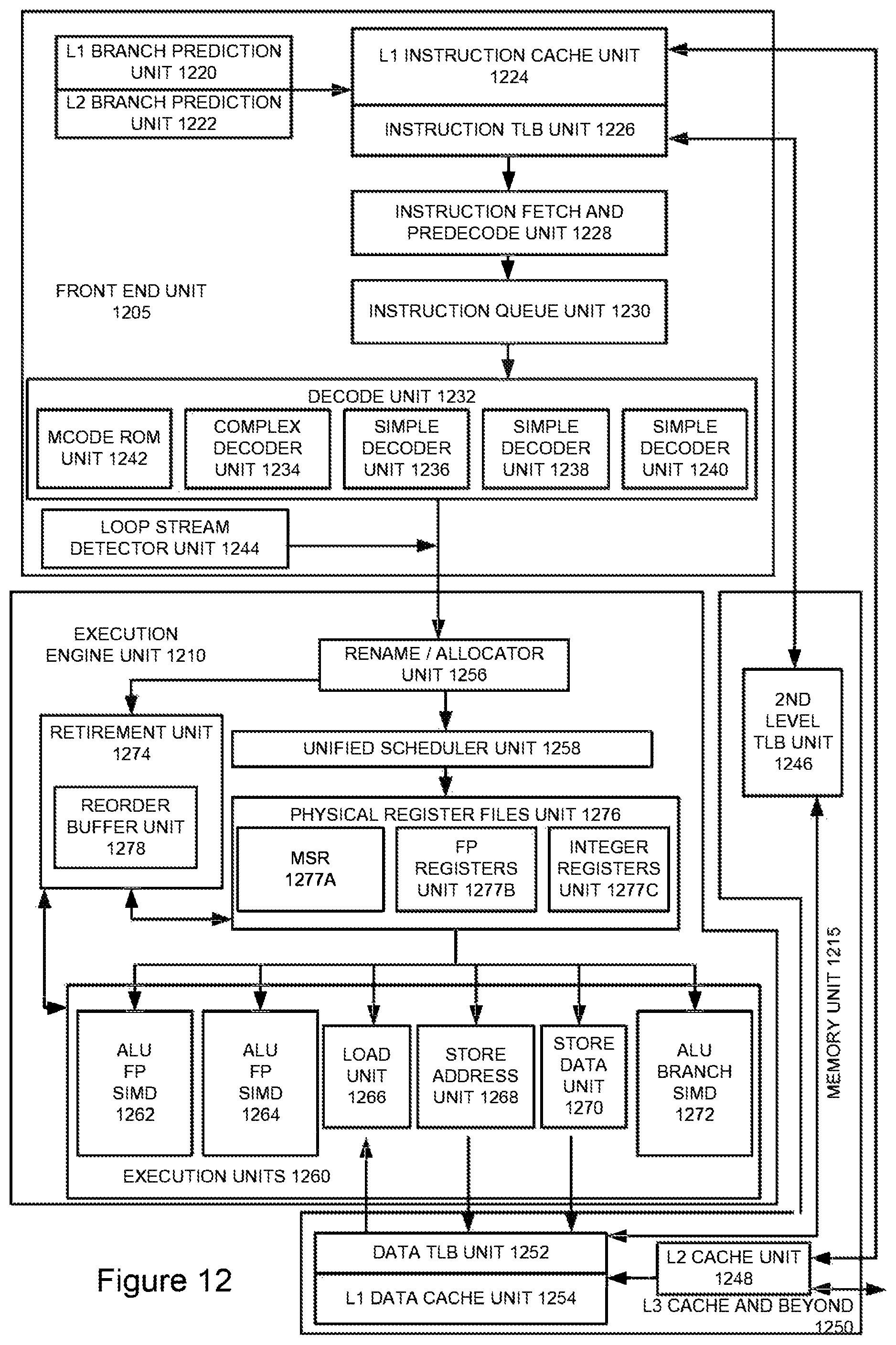
D00013
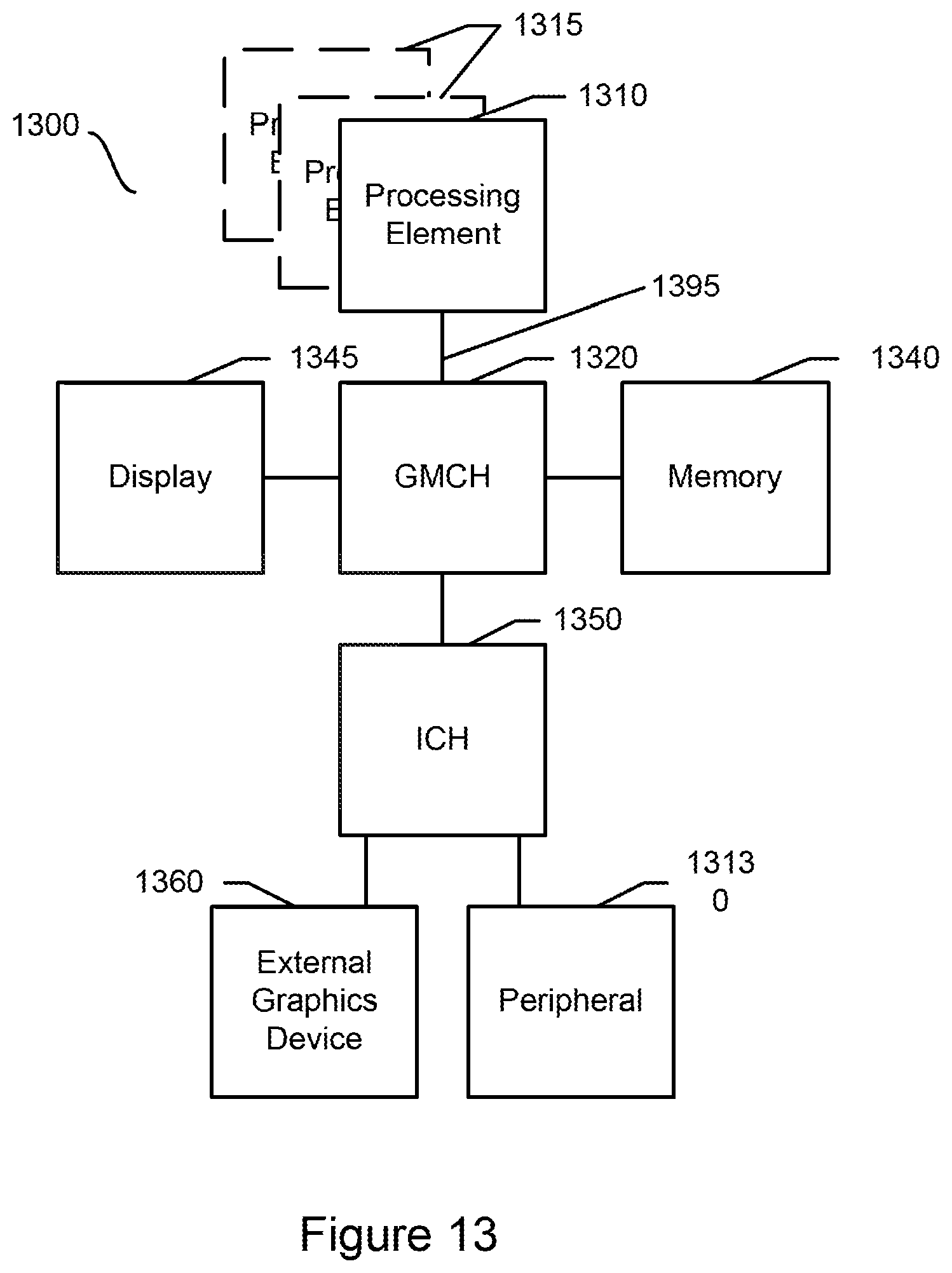
D00014
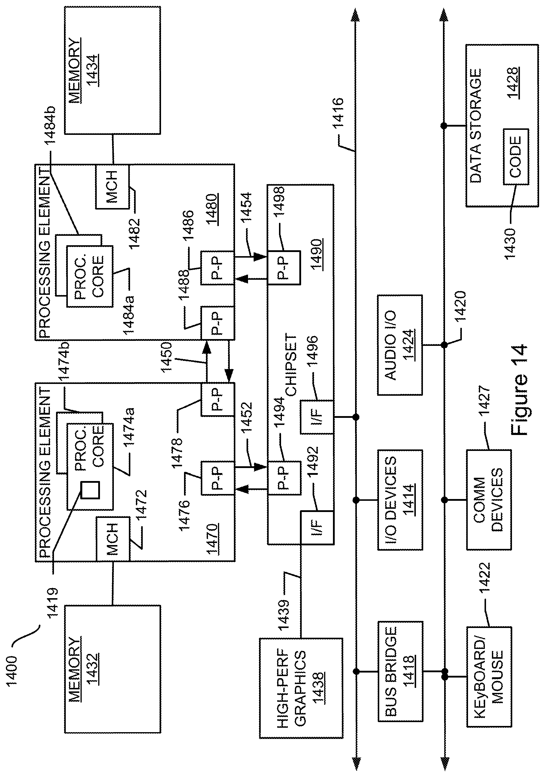
D00015
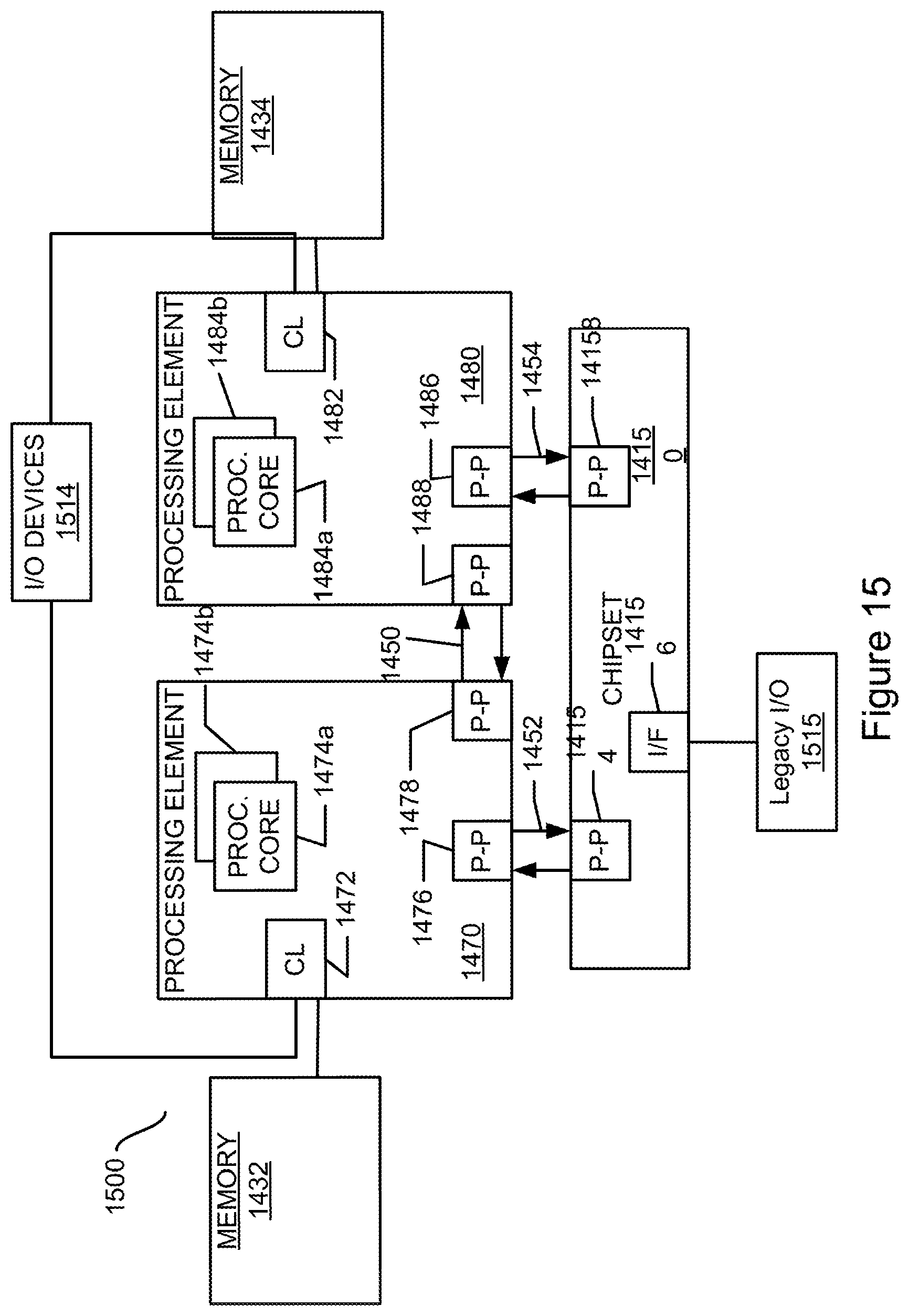
XML
uspto.report is an independent third-party trademark research tool that is not affiliated, endorsed, or sponsored by the United States Patent and Trademark Office (USPTO) or any other governmental organization. The information provided by uspto.report is based on publicly available data at the time of writing and is intended for informational purposes only.
While we strive to provide accurate and up-to-date information, we do not guarantee the accuracy, completeness, reliability, or suitability of the information displayed on this site. The use of this site is at your own risk. Any reliance you place on such information is therefore strictly at your own risk.
All official trademark data, including owner information, should be verified by visiting the official USPTO website at www.uspto.gov. This site is not intended to replace professional legal advice and should not be used as a substitute for consulting with a legal professional who is knowledgeable about trademark law.