Catheter assembly/package utilizing a hydrating/hydrogel sleeve and a foil outer layer and method of making and using the same
Terry
U.S. patent number 10,702,671 [Application Number 16/453,809] was granted by the patent office on 2020-07-07 for catheter assembly/package utilizing a hydrating/hydrogel sleeve and a foil outer layer and method of making and using the same. This patent grant is currently assigned to C. R. Bard, Inc.. The grantee listed for this patent is C. R. Bard, Inc.. Invention is credited to Richard Terry.


| United States Patent | 10,702,671 |
| Terry | July 7, 2020 |
Catheter assembly/package utilizing a hydrating/hydrogel sleeve and a foil outer layer and method of making and using the same
Abstract
A catheter assembly package includes a hydrating sleeve and a catheter disposed in the hydrating sleeve, the hydrating sleeve and the catheter enclosed in a sealed package. A coating can be disposed on an outer surface of the catheter and in contact with an inner surface of the hydrating sleeve. The hydrating sleeve can include a fluid and an outer foil layer, and the fluid can be confined to the hydrating sleeve. The sealed package can enclose the hydrating sleeve in a first compartment and the catheter in a second compartment.
| Inventors: | Terry; Richard (Conyers, GA) | ||||||||||
|---|---|---|---|---|---|---|---|---|---|---|---|
| Applicant: |
|
||||||||||
| Assignee: | C. R. Bard, Inc. (Franklin
Lakes, NJ) |
||||||||||
| Family ID: | 44542536 | ||||||||||
| Appl. No.: | 16/453,809 | ||||||||||
| Filed: | June 26, 2019 |
Prior Publication Data
| Document Identifier | Publication Date | |
|---|---|---|
| US 20190381272 A1 | Dec 19, 2019 | |
Related U.S. Patent Documents
| Application Number | Filing Date | Patent Number | Issue Date | ||
|---|---|---|---|---|---|
| 15669697 | Jul 9, 2019 | 10342952 | |||
| 14707954 | Aug 15, 2017 | 9731093 | |||
| 13582698 | May 19, 2015 | 9033149 | |||
| PCT/US2011/026681 | Mar 1, 2011 | ||||
| 61310535 | Mar 4, 2010 | ||||
| Current U.S. Class: | 1/1 |
| Current CPC Class: | B65D 81/22 (20130101); A61M 25/002 (20130101); A61F 2/042 (20130101); A61M 25/0017 (20130101); A61M 25/0045 (20130101); B65D 65/38 (20130101); B65D 77/04 (20130101); A61M 2025/0046 (20130101); A61M 2025/0047 (20130101) |
| Current International Class: | A61M 25/00 (20060101); B65D 77/04 (20060101); B65D 81/22 (20060101); B65D 65/38 (20060101); A61F 2/04 (20130101) |
| Field of Search: | ;206/571,363,364,210 ;604/265,172,554 |
References Cited [Referenced By]
U.S. Patent Documents
| 1888349 | November 1932 | Jacoby |
| 2912981 | November 1959 | Keough |
| 2919697 | January 1960 | Kim |
| 3173566 | March 1965 | Talbert |
| 3246075 | April 1966 | Dansard |
| 3344791 | October 1967 | Foderick |
| 3345988 | October 1967 | Vitello |
| 3556294 | January 1971 | Walck et al. |
| 3556874 | January 1971 | McClain |
| 3566874 | March 1971 | Shepherd et al. |
| 3648704 | March 1972 | Jackson |
| 3695921 | October 1972 | Shepherd et al. |
| 3699964 | October 1972 | Ericson |
| 3726281 | April 1973 | Norton et al. |
| 3794042 | February 1974 | De Klotz et al. |
| 3802987 | April 1974 | Noll |
| 3835992 | September 1974 | Adams, IV |
| 3854483 | December 1974 | Powers |
| 3861395 | January 1975 | Taniguchi |
| 3894540 | July 1975 | Bonner, Jr. |
| 3898993 | August 1975 | Taniguchi |
| 3934721 | January 1976 | Juster et al. |
| 3967728 | July 1976 | Gordon et al. |
| 4026296 | May 1977 | Stoy et al. |
| 4051849 | October 1977 | Poncy et al. |
| 4055682 | October 1977 | Merrill |
| 4062363 | December 1977 | Bonner, Jr. |
| 4069359 | January 1978 | DeMarse et al. |
| 4091922 | May 1978 | Egler |
| 4140127 | February 1979 | Cianci et al. |
| 4198983 | April 1980 | Becker et al. |
| 4230115 | October 1980 | Walz, Jr. et al. |
| 4245639 | January 1981 | La Rosa |
| 4246909 | January 1981 | Wu et al. |
| 4269310 | May 1981 | Uson |
| 4306557 | December 1981 | North |
| 4350161 | September 1982 | Davis, Jr. |
| 4351333 | September 1982 | Lazarus et al. |
| 4366901 | January 1983 | Short |
| 4392848 | July 1983 | Lucas et al. |
| 4411648 | October 1983 | Davis et al. |
| 4515593 | May 1985 | Norton |
| 4517971 | May 1985 | Sorbonne |
| 4560382 | December 1985 | Isono et al. |
| 4571241 | February 1986 | Christopher |
| 4585666 | April 1986 | Lambert |
| 4597765 | July 1986 | Klatt |
| 4607746 | August 1986 | Stinnette |
| 4610670 | September 1986 | Spencer |
| 4619642 | October 1986 | Spencer |
| 4681572 | July 1987 | Tokarz et al. |
| 4692154 | September 1987 | Singery et al. |
| 4696672 | September 1987 | Mochizuki et al. |
| 4704102 | November 1987 | Guthery |
| 4723946 | February 1988 | Kay |
| 4738667 | April 1988 | Galloway |
| 4754877 | July 1988 | Johansson et al. |
| 4759753 | July 1988 | Schneider et al. |
| 4762128 | August 1988 | Rosenbluth |
| 4773901 | September 1988 | Norton |
| 4784651 | November 1988 | Hickey et al. |
| 4811847 | March 1989 | Reif et al. |
| 4838876 | June 1989 | Wong et al. |
| 4886508 | December 1989 | Washington |
| 4888005 | December 1989 | Dingeman et al. |
| 4893623 | January 1990 | Rosenbluth |
| 4932938 | June 1990 | Goldberg et al. |
| 4957487 | September 1990 | Gerow |
| 4997426 | March 1991 | Dingeman et al. |
| 5007897 | April 1991 | Kalb et al. |
| 5045078 | September 1991 | Asta |
| 5077352 | December 1991 | Elton |
| 5087252 | February 1992 | Denard |
| 5098379 | March 1992 | Conway et al. |
| 5100396 | March 1992 | Zamierowski |
| 5137671 | August 1992 | Conway et al. |
| 5147341 | September 1992 | Starke et al. |
| 5174290 | December 1992 | Fiddian-Green |
| 5179174 | January 1993 | Elton |
| 5180591 | January 1993 | Magruder et al. |
| 5186172 | February 1993 | Fiddian-Green |
| 5188596 | February 1993 | Condon et al. |
| 5201724 | April 1993 | Hukins et al. |
| 5209726 | May 1993 | Goosen |
| 5209728 | May 1993 | Kraus et al. |
| 5224953 | July 1993 | Morgentaler |
| 5226530 | July 1993 | Golden |
| 5234411 | August 1993 | Vaillancourt et al. |
| 5236422 | August 1993 | Eplett, Jr. |
| 5242398 | September 1993 | Knoll et al. |
| 5242428 | September 1993 | Palestrant |
| 5261896 | November 1993 | Conway et al. |
| 5269755 | December 1993 | Bodicky |
| 5269770 | December 1993 | Conway et al. |
| 5282795 | February 1994 | Finney |
| 5352182 | October 1994 | Kalb et al. |
| 5360402 | November 1994 | Conway et al. |
| 5370899 | December 1994 | Conway et al. |
| 5415165 | May 1995 | Fiddian-Green |
| 5417666 | May 1995 | Coulter |
| 5433713 | July 1995 | Trotta |
| 5445626 | August 1995 | Gigante et al. |
| 5447231 | September 1995 | Kastenhofer |
| 5454798 | October 1995 | Kubalak et al. |
| 5456251 | October 1995 | Fiddian-Green |
| 5466229 | November 1995 | Elson et al. |
| 5476434 | December 1995 | Kalb et al. |
| 5482740 | January 1996 | Conway et al. |
| 5501669 | March 1996 | Conway et al. |
| 5509889 | April 1996 | Kalb et al. |
| 5514112 | May 1996 | Chu et al. |
| 5520636 | May 1996 | Korth et al. |
| 5531715 | July 1996 | Engelson et al. |
| 5531717 | July 1996 | Roberto et al. |
| 5536258 | July 1996 | Folden |
| 5558900 | September 1996 | Fan et al. |
| 5569219 | October 1996 | Hakki et al. |
| 5582599 | December 1996 | Daneshvar |
| 5591292 | January 1997 | Blomqvist |
| 5599321 | February 1997 | Conway et al. |
| 5601537 | February 1997 | Frassica |
| 5607417 | March 1997 | Batich et al. |
| 5616126 | April 1997 | Malekmehr et al. |
| 5624395 | April 1997 | Mikhail et al. |
| 5653700 | August 1997 | Byrne et al. |
| 5670111 | September 1997 | Conway et al. |
| 5688516 | November 1997 | Raad et al. |
| 5695456 | December 1997 | Cartmell et al. |
| 5704353 | January 1998 | Kalb et al. |
| 5707357 | January 1998 | Mikhail et al. |
| 5711841 | January 1998 | Jaker |
| 5749826 | May 1998 | Faulkner |
| 5779670 | July 1998 | Bidwell et al. |
| 5782808 | July 1998 | Folden |
| 5785694 | July 1998 | Cohen et al. |
| 5788687 | August 1998 | Batich et al. |
| 5800339 | September 1998 | Salama |
| 5817067 | October 1998 | Tsukada et al. |
| 5820583 | October 1998 | Demopulos et al. |
| 5840151 | November 1998 | Munsch |
| 5848691 | December 1998 | Morris et al. |
| 5853518 | December 1998 | Utas |
| 5871475 | February 1999 | Frassica |
| 5895374 | April 1999 | Rodsten |
| 5897535 | April 1999 | Feliziani et al. |
| 5941856 | August 1999 | Kovacs et al. |
| 5958167 | September 1999 | Van Driel et al. |
| 5971954 | October 1999 | Conway et al. |
| 5980483 | November 1999 | Dimitri |
| 5989230 | November 1999 | Frassica |
| 6004305 | December 1999 | Hursman et al. |
| 6007521 | December 1999 | Bidwell et al. |
| 6024751 | February 2000 | Lovato et al. |
| 6050934 | April 2000 | Mikhail et al. |
| 6053905 | April 2000 | Daignault, Jr. et al. |
| 6056715 | May 2000 | Demopulos et al. |
| 6059107 | May 2000 | Nosted et al. |
| 6063063 | May 2000 | Harboe et al. |
| 6090075 | July 2000 | House |
| 6156049 | December 2000 | Lovato et al. |
| 6162201 | December 2000 | Cohen et al. |
| 6183461 | February 2001 | Matsuura et al. |
| 6186990 | February 2001 | Chen et al. |
| 6190353 | February 2001 | Makower et al. |
| 6210394 | April 2001 | Demopulos et al. |
| 6217569 | April 2001 | Fiore |
| 6221056 | April 2001 | Silverman |
| 6238383 | May 2001 | Karram et al. |
| 6254570 | July 2001 | Rutner et al. |
| 6254582 | July 2001 | O'Donnell et al. |
| 6254585 | July 2001 | Demopulos et al. |
| 6261279 | July 2001 | Demopulos et al. |
| 6293923 | September 2001 | Yachia et al. |
| 6299598 | October 2001 | Bander |
| 6306422 | October 2001 | Batich et al. |
| 6329488 | December 2001 | Terry et al. |
| 6340359 | January 2002 | Silverman |
| 6355004 | March 2002 | Pedersen et al. |
| 6358229 | March 2002 | Tihon |
| 6368315 | April 2002 | Gillis et al. |
| 6368317 | April 2002 | Chang |
| 6379334 | April 2002 | Frassica |
| 6383434 | May 2002 | Conway et al. |
| 6391010 | May 2002 | Wilcox |
| 6391014 | May 2002 | Silverman |
| 6398718 | June 2002 | Yachia et al. |
| 6402726 | June 2002 | Genese |
| 6409717 | June 2002 | Israelsson et al. |
| 6458867 | October 2002 | Wang et al. |
| 6468245 | October 2002 | Alexandersen |
| 6485476 | November 2002 | von Dyck et al. |
| 6544240 | April 2003 | Borodulin et al. |
| 6578709 | June 2003 | Kavanagh et al. |
| 6582401 | June 2003 | Windheuser et al. |
| 6602244 | August 2003 | Kavanagh et al. |
| 6613342 | September 2003 | Aoki |
| 6626888 | September 2003 | Conway et al. |
| 6629969 | October 2003 | Chan et al. |
| 6634498 | October 2003 | Kayerod et al. |
| 6638269 | October 2003 | Wilcox |
| 6648906 | November 2003 | Lasheras et al. |
| 6659937 | December 2003 | Polsky et al. |
| 6682555 | January 2004 | Cioanta et al. |
| 6695831 | February 2004 | Tsukada et al. |
| 6711436 | March 2004 | Duhaylongsod |
| 6716895 | April 2004 | Terry |
| 6719709 | April 2004 | Whalen et al. |
| 6730113 | May 2004 | Eckhardt et al. |
| 6736805 | May 2004 | Israelsson et al. |
| 6746421 | June 2004 | Yachia et al. |
| 6783520 | August 2004 | Candray et al. |
| D496266 | September 2004 | Nestenborg |
| 6824532 | November 2004 | Gillis et al. |
| 6835183 | December 2004 | Lennox et al. |
| 6840379 | January 2005 | Franks-Farah et al. |
| 6848574 | February 2005 | Israelsson et al. |
| 6849070 | February 2005 | Hansen et al. |
| 6852105 | February 2005 | Bolmsjo et al. |
| D503335 | March 2005 | Risberg et al. |
| 6869416 | March 2005 | Windheuser et al. |
| 6887230 | May 2005 | Kubalak et al. |
| 6889740 | May 2005 | Globensky et al. |
| 6918924 | July 2005 | Lasheras et al. |
| 6926708 | August 2005 | Franks-Farah et al. |
| 6939339 | September 2005 | Axexandersen et al. |
| 6941171 | September 2005 | Mann et al. |
| 6942634 | September 2005 | Odland |
| 6945957 | September 2005 | Freyman |
| 6949598 | September 2005 | Terry |
| 7001370 | February 2006 | Kubalak et al. |
| 7048717 | May 2006 | Frassica |
| 7059330 | June 2006 | Makower et al. |
| 7066912 | June 2006 | Nestenborg et al. |
| 7087041 | August 2006 | von Dyck et al. |
| 7087048 | August 2006 | Israelsson et al. |
| 7094220 | August 2006 | Tanghoj et al. |
| 7160277 | January 2007 | Elson et al. |
| 7166092 | January 2007 | Elson et al. |
| 7195608 | March 2007 | Burnett |
| 7244242 | July 2007 | Freyman |
| 7250043 | July 2007 | Chan et al. |
| 7255687 | August 2007 | Huang et al. |
| 7270647 | September 2007 | Karpowicz et al. |
| 7294117 | November 2007 | Provost-tine et al. |
| 7311690 | December 2007 | Burnett |
| 7311698 | December 2007 | Tanghoj et al. |
| 7331948 | February 2008 | Skarda |
| 7334679 | February 2008 | Givens, Jr. |
| 7374040 | May 2008 | Lee et al. |
| 7380658 | June 2008 | Murray et al. |
| 7445812 | November 2008 | Schmidt et al. |
| 7458964 | December 2008 | Mosler et al. |
| 7476223 | January 2009 | McBride |
| 7507229 | March 2009 | Hewitt et al. |
| 7517343 | April 2009 | Tanghoj et al. |
| 7537589 | May 2009 | Tsukada et al. |
| 7571804 | August 2009 | Bruun et al. |
| 7601158 | October 2009 | House |
| 7615045 | November 2009 | Israelsson et al. |
| 7628784 | December 2009 | Diaz et al. |
| 7632256 | December 2009 | Mosier et al. |
| 7662146 | February 2010 | House |
| 7682353 | March 2010 | Tanghoj et al. |
| 7770726 | August 2010 | Murray et al. |
| 7789873 | September 2010 | Kubalak et al. |
| 7823722 | November 2010 | Bezou et al. |
| 7846133 | December 2010 | Windheuser et al. |
| 7938838 | May 2011 | House |
| 7947021 | May 2011 | Bourne et al. |
| 7985217 | July 2011 | Mosler et al. |
| 8011505 | September 2011 | Murray et al. |
| 8051981 | November 2011 | Murray et al. |
| 8066693 | November 2011 | Tanghoj et al. |
| 8177774 | May 2012 | House |
| 8181778 | May 2012 | van Groningen et al. |
| 8205745 | June 2012 | Murray et al. |
| 8328792 | December 2012 | Nishtala et al. |
| 8454569 | June 2013 | Kull-Osterlin et al. |
| 8459455 | June 2013 | Frojd |
| 8475434 | July 2013 | Frojd |
| 8998882 | April 2015 | Knapp et al. |
| 9033149 | May 2015 | Terry |
| 9114227 | August 2015 | Blanchard |
| 9694113 | July 2017 | Knapp et al. |
| 9731093 | August 2017 | Terry |
| 9821139 | November 2017 | Carleo |
| 10149961 | December 2018 | Carleo |
| 2001/0001443 | May 2001 | Kayerod et al. |
| 2001/0031952 | October 2001 | Karram et al. |
| 2001/0047147 | November 2001 | Slepian et al. |
| 2001/0054562 | December 2001 | Pettersson et al. |
| 2002/0007175 | January 2002 | Chang |
| 2002/0037943 | March 2002 | Madsen |
| 2002/0045855 | April 2002 | Frassica |
| 2002/0055730 | May 2002 | Yachia et al. |
| 2002/0077611 | June 2002 | von Dyck et al. |
| 2002/0082551 | June 2002 | Yachia et al. |
| 2002/0087131 | July 2002 | Wolff et al. |
| 2002/0094322 | July 2002 | Lawson et al. |
| 2002/0095133 | July 2002 | Gillis et al. |
| 2002/0099356 | July 2002 | Unger et al. |
| 2002/0103467 | August 2002 | Kubalak |
| 2002/0107467 | August 2002 | Levin |
| 2002/0132013 | September 2002 | Moulis |
| 2002/0133130 | September 2002 | Wilcox |
| 2002/0156440 | October 2002 | Israelsson et al. |
| 2002/0165427 | November 2002 | Yachia et al. |
| 2003/0004496 | January 2003 | Tanghoj |
| 2003/0018293 | January 2003 | Tanghoj et al. |
| 2003/0018302 | January 2003 | Kavanagh et al. |
| 2003/0018322 | January 2003 | Tanghoj et al. |
| 2003/0028174 | February 2003 | Chan et al. |
| 2003/0036802 | February 2003 | Lennox et al. |
| 2003/0055403 | March 2003 | Nestenborg et al. |
| 2003/0060807 | March 2003 | Tanghoj et al. |
| 2003/0065292 | April 2003 | Darouiche et al. |
| 2003/0130646 | July 2003 | Kubalak et al. |
| 2003/0132307 | July 2003 | Park |
| 2003/0135200 | July 2003 | Byrne |
| 2003/0163079 | August 2003 | Burnett |
| 2003/0195478 | October 2003 | Russo |
| 2003/0225392 | December 2003 | McMichael et al. |
| 2003/0233084 | December 2003 | Slepian et al. |
| 2004/0030301 | February 2004 | Hunter |
| 2004/0034329 | February 2004 | Mankus et al. |
| 2004/0044307 | March 2004 | Richardson et al. |
| 2004/0049152 | March 2004 | Nayak |
| 2004/0049170 | March 2004 | Snell |
| 2004/0055925 | March 2004 | Franks-Farah et al. |
| 2004/0059280 | March 2004 | Makower et al. |
| 2004/0068251 | April 2004 | Chan et al. |
| 2004/0074794 | April 2004 | Conway et al. |
| 2004/0116551 | June 2004 | Terry |
| 2004/0127848 | July 2004 | Freyman |
| 2004/0133156 | July 2004 | Diaz et al. |
| 2004/0147871 | July 2004 | Burnett |
| 2004/0153049 | August 2004 | Hewitt et al. |
| 2004/0153051 | August 2004 | Israelsson et al. |
| 2004/0158231 | August 2004 | Tanghoj et al. |
| 2004/0163980 | August 2004 | Tanghoj et al. |
| 2004/0176747 | September 2004 | Feneley |
| 2004/0243104 | December 2004 | Seddon |
| 2004/0249343 | December 2004 | Cioanta |
| 2004/0254562 | December 2004 | Tanghoj et al. |
| 2004/0256264 | December 2004 | Israelsson et al. |
| 2005/0003118 | January 2005 | Takala |
| 2005/0015076 | January 2005 | Giebmeyer et al. |
| 2005/0031872 | February 2005 | Schmidt et al. |
| 2005/0033222 | February 2005 | Haggstrom et al. |
| 2005/0043715 | February 2005 | Nestenborg et al. |
| 2005/0049577 | March 2005 | Snell et al. |
| 2005/0059990 | March 2005 | Ayala et al. |
| 2005/0065499 | March 2005 | Douk et al. |
| 2005/0070882 | March 2005 | McBride |
| 2005/0080399 | April 2005 | Bolmsjo et al. |
| 2005/0096582 | May 2005 | Burnett |
| 2005/0101923 | May 2005 | Elson et al. |
| 2005/0101924 | May 2005 | Elson et al. |
| 2005/0107735 | May 2005 | Lennox et al. |
| 2005/0109648 | May 2005 | Kerzman et al. |
| 2005/0137522 | June 2005 | Aoki |
| 2005/0137582 | June 2005 | Kull-Osterlin et al. |
| 2005/0143690 | June 2005 | High |
| 2005/0148950 | July 2005 | Windheuser et al. |
| 2005/0197531 | September 2005 | Cabiri et al. |
| 2005/0199521 | September 2005 | Givens |
| 2005/0209580 | September 2005 | Freyman |
| 2005/0214443 | September 2005 | Madsen |
| 2005/0245901 | November 2005 | Floyd |
| 2005/0251108 | November 2005 | Frassica |
| 2005/0256447 | November 2005 | Richardson et al. |
| 2005/0273034 | December 2005 | Burnett |
| 2005/0283136 | December 2005 | Skarda |
| 2006/0025753 | February 2006 | Kubalak et al. |
| 2006/0027854 | February 2006 | Kim et al. |
| 2006/0030864 | February 2006 | Kennedy et al. |
| 2006/0036208 | February 2006 | Burnett |
| 2006/0041246 | February 2006 | Provost-tine et al. |
| 2006/0054557 | March 2006 | Hori et al. |
| 2006/0058777 | March 2006 | Nielsen |
| 2006/0064065 | March 2006 | Russo |
| 2006/0079835 | April 2006 | Frassica |
| 2006/0079854 | April 2006 | Kay et al. |
| 2006/0100511 | May 2006 | Eriksen |
| 2006/0122566 | June 2006 | Huang et al. |
| 2006/0122568 | June 2006 | Elson et al. |
| 2006/0163097 | July 2006 | Murray et al. |
| 2006/0172096 | August 2006 | Kyle et al. |
| 2006/0184112 | August 2006 | Horn et al. |
| 2006/0184145 | August 2006 | Ciok et al. |
| 2006/0196783 | September 2006 | Bruun et al. |
| 2006/0200079 | September 2006 | Magnusson |
| 2006/0263404 | November 2006 | Nielsen et al. |
| 2006/0271019 | November 2006 | Stoller et al. |
| 2006/0276894 | December 2006 | Finley |
| 2006/0278546 | December 2006 | State et al. |
| 2006/0293642 | December 2006 | Israelsson et al. |
| 2007/0005041 | January 2007 | Frassica et al. |
| 2007/0010798 | January 2007 | Stoller et al. |
| 2007/0016169 | January 2007 | Utas et al. |
| 2007/0049879 | March 2007 | Gutierrez |
| 2007/0066963 | March 2007 | Tanghoj |
| 2007/0106233 | May 2007 | Huang et al. |
| 2007/0112327 | May 2007 | Yun et al. |
| 2007/0149929 | June 2007 | Utas et al. |
| 2007/0197957 | August 2007 | Hunter et al. |
| 2007/0225635 | September 2007 | Lynn |
| 2007/0225649 | September 2007 | House |
| 2007/0225687 | September 2007 | House |
| 2007/0244449 | October 2007 | Najafi et al. |
| 2007/0289887 | December 2007 | Murray et al. |
| 2008/0006554 | January 2008 | Duffy et al. |
| 2008/0015518 | January 2008 | Huang et al. |
| 2008/0021382 | January 2008 | Freyman |
| 2008/0027414 | January 2008 | Tanghoj et al. |
| 2008/0033471 | February 2008 | Paz et al. |
| 2008/0050446 | February 2008 | Ziegler et al. |
| 2008/0051762 | February 2008 | Tsukada et al. |
| 2008/0051763 | February 2008 | Frojd |
| 2008/0077099 | March 2008 | House |
| 2008/0082051 | April 2008 | Miller et al. |
| 2008/0085949 | April 2008 | McGhee |
| 2008/0091145 | April 2008 | House |
| 2008/0097362 | April 2008 | Mosler et al. |
| 2008/0097394 | April 2008 | Lampropoulos et al. |
| 2008/0097411 | April 2008 | House |
| 2008/0140010 | June 2008 | Kennedy et al. |
| 2008/0140052 | June 2008 | Moller et al. |
| 2008/0171973 | July 2008 | House |
| 2008/0171998 | July 2008 | House |
| 2008/0172016 | July 2008 | House |
| 2008/0172042 | July 2008 | House |
| 2008/0179208 | July 2008 | Murray et al. |
| 2008/0200907 | August 2008 | Nestenborg |
| 2008/0243091 | October 2008 | Humphreys et al. |
| 2008/0249467 | October 2008 | Burnett et al. |
| 2008/0249482 | October 2008 | Erez |
| 2008/0275463 | November 2008 | High |
| 2009/0024111 | January 2009 | Borodulin et al. |
| 2009/0048537 | February 2009 | Lydon et al. |
| 2009/0054876 | February 2009 | Borodulin et al. |
| 2009/0065605 | March 2009 | Roche et al. |
| 2009/0071851 | March 2009 | Maki et al. |
| 2009/0099532 | April 2009 | Cuevas et al. |
| 2009/0131917 | May 2009 | Kavanagh et al. |
| 2009/0137985 | May 2009 | Tanghoej et al. |
| 2009/0137986 | May 2009 | Golden et al. |
| 2009/0149837 | June 2009 | Tanghoj et al. |
| 2009/0156882 | June 2009 | Chi Sing et al. |
| 2009/0200187 | August 2009 | Nestenborg et al. |
| 2009/0299334 | December 2009 | Nishtala et al. |
| 2009/0318900 | December 2009 | Tanghoj et al. |
| 2010/0198195 | August 2010 | Nishtala et al. |
| 2010/0228233 | September 2010 | Kahn |
| 2010/0263327 | October 2010 | Murray et al. |
| 2010/0324540 | December 2010 | Paulen et al. |
| 2011/0028943 | February 2011 | Lawson et al. |
| 2011/0056852 | March 2011 | Frojd |
| 2011/0114520 | May 2011 | Matthison-Hansen |
| 2011/0127186 | June 2011 | Enns et al. |
| 2011/0137296 | June 2011 | Tanghoj |
| 2011/0184386 | July 2011 | House |
| 2012/0168324 | July 2012 | Carleo |
| 2012/0179102 | July 2012 | Blanchard et al. |
| 2012/0308805 | December 2012 | Sella |
| 2012/0316515 | December 2012 | Terry |
| 2013/0006226 | January 2013 | Hong et al. |
| 2013/0048516 | February 2013 | Nishtala et al. |
| 2013/0153446 | June 2013 | Utas et al. |
| 2013/0186778 | July 2013 | Terry |
| 2014/0262859 | September 2014 | Knapp et al. |
| 2015/0238726 | August 2015 | Terry |
| 2015/0273116 | October 2015 | Knapp et al. |
| 2017/0296704 | October 2017 | Knapp et al. |
| 2017/0326334 | November 2017 | Terry |
| 2770300 | Feb 2011 | CA | |||
| 2769026 | Apr 2015 | CA | |||
| 102939127 | Feb 2013 | CN | |||
| 100 38 521 | Feb 2002 | DE | |||
| 10213411 | Oct 2003 | DE | |||
| 247559 | Dec 1987 | EP | |||
| 0252918 | Jan 1988 | EP | |||
| 0217771 | Dec 1991 | EP | |||
| 0479935 | Apr 1992 | EP | |||
| 0677299 | Oct 1995 | EP | |||
| 0699086 | Mar 1996 | EP | |||
| 0815037 | Jan 1998 | EP | |||
| 0909249 | Apr 1999 | EP | |||
| 0923398 | Jun 1999 | EP | |||
| 0935478 | Aug 1999 | EP | |||
| 0977610 | Feb 2000 | EP | |||
| 1023882 | Aug 2000 | EP | |||
| 1115450 | Jul 2001 | EP | |||
| 1131022 | Sep 2001 | EP | |||
| 1175355 | Jan 2002 | EP | |||
| 1237615 | Sep 2002 | EP | |||
| 1245205 | Oct 2002 | EP | |||
| 0959930 | Dec 2002 | EP | |||
| 1308146 | May 2003 | EP | |||
| 1406690 | Apr 2004 | EP | |||
| 1409060 | Apr 2004 | EP | |||
| 1090656 | May 2004 | EP | |||
| 1420846 | May 2004 | EP | |||
| 1420847 | May 2004 | EP | |||
| 1427467 | Jun 2004 | EP | |||
| 1498151 | Jan 2005 | EP | |||
| 1145729 | Nov 2005 | EP | |||
| 1629860 | Mar 2006 | EP | |||
| 1641510 | Apr 2006 | EP | |||
| 1642610 | Apr 2006 | EP | |||
| 1642611 | Apr 2006 | EP | |||
| 2060296 | May 2009 | EP | |||
| 2459264 | Jun 2012 | EP | |||
| 2464411 | Jun 2012 | EP | |||
| 2515988 | Oct 2012 | EP | |||
| 2542291 | Jan 2013 | EP | |||
| 3078393 | Nov 2017 | EP | |||
| 2967968 | Sep 2018 | EP | |||
| 2731345 | Sep 1996 | FR | |||
| 2 794 638 | Dec 2000 | FR | |||
| 2319507 | May 1998 | GB | |||
| 2284764 | Aug 1998 | GB | |||
| S55-12265 | Mar 1980 | JP | |||
| 2001-500414 | Jan 2001 | JP | |||
| 2002-530148 | Sep 2002 | JP | |||
| 2002 282275 | Oct 2002 | JP | |||
| 2007-501656 | Feb 2007 | JP | |||
| 2011-510110 | Mar 2011 | JP | |||
| 2013-500125 | Jan 2013 | JP | |||
| 2013-515572 | May 2013 | JP | |||
| 2009105497 | Aug 2010 | RU | |||
| 198401296 | Apr 1984 | WO | |||
| 1986006284 | Nov 1986 | WO | |||
| 1991005577 | May 1991 | WO | |||
| 1994016747 | Aug 1994 | WO | |||
| 1996038192 | Dec 1996 | WO | |||
| 1997026937 | Jul 1997 | WO | |||
| 1997041811 | Nov 1997 | WO | |||
| 1998006642 | Feb 1998 | WO | |||
| 1998011932 | Mar 1998 | WO | |||
| 1998019729 | May 1998 | WO | |||
| 98/46176 | Oct 1998 | WO | |||
| 1999030761 | Jun 1999 | WO | |||
| 2000016843 | Mar 2000 | WO | |||
| 2000047494 | Aug 2000 | WO | |||
| 2001043807 | Jun 2001 | WO | |||
| 2001052763 | Jul 2001 | WO | |||
| 2001093935 | Dec 2001 | WO | |||
| 2002036192 | May 2002 | WO | |||
| 2003002177 | Jan 2003 | WO | |||
| 2003002178 | Jan 2003 | WO | |||
| 2003008028 | Jan 2003 | WO | |||
| 2003008029 | Jan 2003 | WO | |||
| 2003064279 | Aug 2003 | WO | |||
| 2003092779 | Nov 2003 | WO | |||
| 2004030722 | Apr 2004 | WO | |||
| 2004045696 | Jun 2004 | WO | |||
| 2004045696 | Jun 2004 | WO | |||
| 2004050155 | Jun 2004 | WO | |||
| 2004052440 | Jun 2004 | WO | |||
| 2004056414 | Jul 2004 | WO | |||
| 2004075944 | Sep 2004 | WO | |||
| 2004089454 | Oct 2004 | WO | |||
| 2005004964 | Jan 2005 | WO | |||
| 2005014055 | Feb 2005 | WO | |||
| 2005061035 | Jul 2005 | WO | |||
| 2005092418 | Oct 2005 | WO | |||
| 2007050685 | May 2007 | WO | |||
| 2007050685 | May 2007 | WO | |||
| 2009012336 | Jan 2009 | WO | |||
| 2007050685 | Apr 2009 | WO | |||
| 2011014201 | Feb 2011 | WO | |||
| 2011019359 | Feb 2011 | WO | |||
| 2011063816 | Jun 2011 | WO | |||
| 2011079129 | Jun 2011 | WO | |||
| 2011109393 | Sep 2011 | WO | |||
| 2014165046 | Oct 2014 | WO | |||
Other References
|
"Tripartite Biocompatibility Guidance for Medical Devices," DSMA (Apr. 24, 1987). cited by applicant . AU 2014248744 filed Jul. 9, 2015 Examiner's Report dated Jul. 26, 2017. cited by applicant . BR PI 0506836-3 filed Jan. 18, 2005, Technical Report dated Jul. 28, 2015. cited by applicant . CA 2,769,026 filed Jan. 24, 2012 First Examination Report dated Nov. 4, 2013. cited by applicant . CN 201080058895.4 filed Jun. 21, 2012 First Office Action dated Feb. 27, 2014. cited by applicant . CN 201080058895.4 filed Jun. 21, 2012 Second Office Action dated Nov. 3, 2014. cited by applicant . CN 201080058895.4 filed Jun. 21, 2012 Third Office Action dated May 4, 2015. cited by applicant . CN 201480013064.3 filed Sep. 8, 2015 Office Action dated Jun. 29, 2017. cited by applicant . CN 201480013064.3 filed Sep. 8, 2015 Office Action dated Oct. 10, 2016. cited by applicant . EP 09848341.5 filed Feb. 27, 2012 extended European Search Report dated Apr. 4, 2013. cited by applicant . EP 09848341.5 filed Feb. 27, 2012 supplemental European Search Report dated Nov. 8, 2013. cited by applicant . EP 10840071.4 filed Jul. 4, 2012 Exam Report dated Apr. 29, 2014. cited by applicant . EP 10840071.4 filed Jul. 4, 2012 extended European Search Report dated Apr. 17, 2013. cited by applicant . EP 10840071.4 filed Jul. 4, 2012 Notice of Opposition dated Apr. 24, 2017. cited by applicant . EP 10840071.4 filed Jul. 4, 2012 Office Action dated Jul. 9, 2015. cited by applicant . EP 11751198.0 filed Sep. 28, 2012 Exam Report dated Feb. 7, 2014. cited by applicant . EP 11751198.0 filed Sep. 28, 2012 extended European search report dated Jul. 9, 2013. cited by applicant . EP 14779919.1 filed Sep. 10, 2015 Extended European Search Report dated Aug. 23, 2016. cited by applicant . EP 14779919.1 filed Sep. 10, 2015 Office Action dated Jul. 4, 2017. cited by applicant . EP 16171279.9 filed May 25, 2016 Extended European Search Report, dated Aug. 23, 2016. cited by applicant . EP 16171279.9 filed May 25, 2016 Intent to Grant, dated Jun. 13, 2017. cited by applicant . EP 17201044.9 filed Nov. 10, 2017 Extended European Search Report dated Jan. 18, 2018. cited by applicant . EP 17201044.9 filed Nov. 10, 2017 Office Action dated Jul. 4, 2019. cited by applicant . JP 2012-546157 filed Jun. 12, 2012 Decision of Rejection dated Aug. 21, 2015. cited by applicant . JP 2012-546157 filed Jun. 12, 2012 First Office Action dated Sep. 16, 2014. cited by applicant . JP 2015-243156 filed Dec. 14, 2015 Office Action dated Sep. 16, 2016. cited by applicant . JP 2016-501444 filed Sep. 11, 2015 Office Action dated Dec. 14, 2017. cited by applicant . MX/a/2015/009904 filed Jul. 30, 2015 Office Action dated Jun. 29, 2018. cited by applicant . Norton, J.A. et al., Surgery: Basic Science and Clinical Evidence Springer, 2nd ed., 2008, p. 281. cited by applicant . PCT/US2006/041633 filed Oct. 25, 2006 International Preliminary Report on Patentability dated Mar. 24, 2009. cited by applicant . PCT/US2006/041633 filed Oct. 25, 2006 Search Report dated Aug. 12, 2008. cited by applicant . PCT/US2006/041633 filed Oct. 25, 2006 Written Opinion dated Aug. 12, 2008. cited by applicant . PCT/US2009/055389 filed Aug. 28, 2009 International Search Report dated Oct. 20, 2009. cited by applicant . PCT/US2009/055389 filed Aug. 28, 2009 Written Opinion dated Oct. 20, 2009. cited by applicant . PCT/US2009/055395 filed Aug. 28, 2009 International Preliminary Report on Patentability dated Jan. 31, 2012. cited by applicant . PCT/US2009/055395 filed Aug. 28, 2009 International Search Report dated Oct. 15, 2009. cited by applicant . PCT/US2009/055395 filed Aug. 28, 2009 Written Opinion dated Oct. 15, 2009. cited by applicant . PCT/US2010/061597 filed Dec. 21, 2010 International Preliminary Report on Patentability dated Jun. 26, 2012 and Written Opinion dated Feb. 28, 2011. cited by applicant . PCT/US2010/061597 filed Dec. 21, 2010 International Search Report dated Feb. 28, 2011. cited by applicant . PCT/US2011/026681 filed Mar. 1, 2011 International Preliminary Report on Patentability dated Sep. 4, 2012. cited by applicant . PCT/US2011/026681 filed Mar. 1, 2011 International Search Report dated Apr. 27, 2011. cited by applicant . PCT/US2011/026681 filed Mar. 1, 2011 Written Opinion dated Apr. 27, 2011. cited by applicant . PCT/US2014/024231 filed Mar. 12, 2014 International Search Report and Written Opinion dated Jul. 10, 2014. cited by applicant . Piyush Gupta et al. Hydrogels: from controlled release to pH-responsive drug delivery, May 2002, DDT vol. 7, No. 10, pp. 569-579. (Year 2002). cited by applicant . RU 2015140616 filed Sep. 24, 2015 Office Action dated Feb. 21, 2018. cited by applicant . U.S. Appl. No. 12/091,916, filed Feb. 2, 2009 Final Office Action dated Sep. 22, 2011. cited by applicant . U.S. Appl. No. 12/091,916, filed Feb. 2, 2009 Non-Final Office Action dated May 10, 2011. cited by applicant . U.S. Appl. No. 12/091,916, filed Feb. 2, 2009 Non-Final Office Action dated Nov. 24, 2010. cited by applicant . U.S. Appl. No. 12/091,916, filed Feb. 2, 2009 Notice of Allowance dated Aug. 17, 2012. cited by applicant . U.S. Appl. No. 13/387,447 filed Mar. 22, 2012 Advisory Action dated Feb. 27, 2014. cited by applicant . U.S. Appl. No. 13/387,447, filed Mar. 22, 2012 Examiner's Answer dated Oct. 5, 2016. cited by applicant . U.S. Appl. No. 13/387,447, filed Mar. 22, 2012 Final Office Action dated Dec. 11, 2013. cited by applicant . U.S. Appl. No. 13/387,447 filed, Mar. 22, 2012 Final Office Action dated Oct. 31, 2014. cited by applicant . U.S. Appl. No. 13/387,447, filed Mar. 22, 2012 Final Office Action dated Oct. 5, 2015. cited by applicant . U.S. Appl. No. 13/387,447, filed Mar. 22, 2012 Non-Final Office Action dated Jan. 15, 2013. cited by applicant . U.S. Appl. No. 13/387,447, filed Mar. 22, 2012 Non-Final Office Action dated Jul. 15, 2014. cited by applicant . U.S. Appl. No. 13/387,447, filed Mar. 22, 2012 Non-Final Office Action dated Jun. 6, 2013. cited by applicant . U.S. Appl. No. 13/387,447, filed Mar. 22, 2012 Non-Final Office Action dated Mar. 12, 2015. cited by applicant . U.S. Appl. No. 13/387,447, filed Mar. 22, 2012 Notice of Allowance dated Jul. 30, 2018. cited by applicant . U.S. Appl. No. 13/387,447, filed Mar. 22, 2012 Patent Board Decision dated Jun. 1, 2018. cited by applicant . U.S. Appl. No. 13/389,753, filed Mar. 20, 2012 Decision on Appeal dated Jun. 29, 2017. cited by applicant . U.S. Appl. No. 13/389,753, filed Mar. 20, 2012 Examiner's Answer dated Aug. 27, 2015. cited by applicant . U.S. Appl. No. 13/389,753, filed Mar. 20, 2012 Final Office Action dated Dec. 10, 2014. cited by applicant . U.S. Appl. No. 13/389,753, filed Mar. 20, 2012 Non-Final Office Action dated Jul. 21, 2014. cited by applicant . U.S. Appl. No. 13/389,753, filed Mar. 20, 2012 Notice of Allowance dated Jul. 5, 2017. cited by applicant . U.S. Appl. No. 13/516,660, filed Aug. 27, 2012 Advisory Action dated Sep. 22, 2016. cited by applicant . U.S. Appl. No. 13/516,660, filed Aug. 27, 2012 Board Decision dated Jan. 22, 2019. cited by applicant . U.S. Appl. No. 13/516,660, filed Aug. 27, 2012 Examinees Answer dated Nov. 22, 2017. cited by applicant . U.S. Appl. No. 13/516,660, filed Aug. 27, 2012 Final Office Action dated Jun. 29, 2016. cited by applicant . U.S. Appl. No. 13/516,660, filed Aug. 27, 2012 Final Office Action dated Sep. 9, 2019. cited by applicant . U.S. Appl. No. 13/516,660, filed Aug. 27, 2012 Non-Final Office Action dated Mar. 15, 2019. cited by applicant . U.S. Appl. No. 13/516,660, filed Aug. 27, 2012 Non-Final Office Action dated Mar. 8, 2016. cited by applicant . U.S. Appl. No. 13/582,698, filed Sep. 4, 2012 Non-Final Office Action dated Sep. 24, 2014. cited by applicant . U.S. Appl. No. 13/662,278, filed Oct. 26, 2012 Board Decision dated Aug. 23, 2018. cited by applicant . U.S. Appl. No. 13/662,278, filed Oct. 26, 2012 Examiner's Answer dated Jun. 2, 2017. cited by applicant . U.S. Appl. No. 13/662,278, filed Oct. 26, 2012 Final Office Action dated Feb. 20, 2015. cited by applicant . U.S. Appl. No. 13/662,278, filed Oct. 26, 2012 Final Office Action dated Oct. 19, 2016. cited by applicant . U.S. Appl. No. 13/662,278, filed Oct. 26, 2012 Non-Final Office Action dated Jul. 7, 2016. cited by applicant . U.S. Appl. No. 13/662,278, filed Oct. 26, 2012 Non-Final Office Action dated Sep. 12, 2014. cited by applicant . U.S. Appl. No. 13/662,278, filed Oct. 26, 2012 Non-Final Office Action dated Sep. 17, 2015. cited by applicant . U.S. Appl. No. 13/802,095, filed Mar. 13, 2013 Non-Final Office Action dated Aug. 15, 2014. cited by applicant . U.S. Appl. No. 13/802,095, filed Mar. 13, 2013 Notice of Allowance dated Nov. 28, 2014. cited by applicant . U.S. Appl. No. 14/681,023, filed Apr. 7, 2015 Non-Final Office Action dated Nov. 9, 2016. cited by applicant . U.S. Appl. No. 14/681,023, filed Apr. 7, 2015 Notice of Allowance dated Mar. 8, 2017. cited by applicant . U.S. Appl. No. 14/707,954, filed May 8, 2015 Non-Final Office Action dated Dec. 1, 2016. cited by applicant . U.S. Appl. No. 15/639,844, filed Jun. 30, 2017 Non-Final Office Action dated Jul. 10, 2019. cited by applicant . U.S. Appl. No. 15/639,844, filed Jun. 30, 2017 Notice of Allowance dated Aug. 13, 2019. cited by applicant . U.S. Appl. No. 15/669,697, filed Aug. 4, 2017 Non-Final Office Action dated Oct. 18, 2018. cited by applicant . U.S. Appl. No. 15/669,697, filed Aug. 4, 2017 Notice of Allowance dated Mar. 1, 2019. cited by applicant. |
Primary Examiner: Cheung; Chun Hoi
Attorney, Agent or Firm: Rutan & Tucker LLP
Parent Case Text
PRIORITY
This application is a continuation of U.S. patent application Ser. No. 15/669,697, filed Aug. 4, 2017, now U.S. Pat. No. 10,342,952, which is a continuation of U.S. patent application Ser. No. 14/707,954, filed May 8, 2015, now U.S. Pat. No. 9,731,093, which is a continuation of U.S. patent application Ser. No. 13/582,698, filed Sep. 4, 2012, now U.S. Pat. No. 9,033,149, which is a U.S. national stage application under 35 U.S.C. .sctn. 371 of International Application No. PCT/US2011/026681, filed Mar. 1, 2011, which claims priority to U.S. Provisional Patent Application No. 61/310,535, filed Mar. 4, 2010, each of which is incorporated by reference into this application as if fully set forth herein.
Claims
What is claimed is:
1. A catheter assembly package, comprising: a hydrating sleeve including a fluid and an outer foil layer; a catheter disposed in the hydrating sleeve, the catheter including a coating on an outer surface in contact with an inner surface of the hydrating sleeve; and a sealed package enclosing the hydrating sleeve and the catheter, the fluid confined to the hydrating sleeve.
2. The catheter assembly package according to claim 1, wherein the sealed package includes a foil layer.
3. The catheter assembly package according to claim 2, wherein the foil layer is a sole layer of the sealed package.
4. The catheter assembly package according to claim 2, wherein the sealed package includes a plurality of layers, the foil layer of the sealed package being an inner layer in contact with the outer foil layer of the hydrating sleeve.
5. The catheter assembly package according to claim 2, wherein the foil layer of the sealed package is secured to the outer foil layer of the hydrating sleeve.
6. The catheter assembly package according to claim 2, wherein the foil layer of the sealed package is generally cylindrical.
7. The catheter assembly package according to claim 1, wherein the hydrating sleeve is structured and arranged to swell when exposed to the fluid.
8. The catheter assembly package according to claim 1, wherein the hydrating sleeve is structured and arranged to absorb about 90% of its weight in fluid.
9. The catheter assembly package according to claim 1, wherein the sealed package is impermeable to fluid.
10. The catheter assembly package according to claim 1, wherein the hydrating sleeve has a wall thickness that is 1/8 inch or greater.
11. The catheter assembly package according to claim 1, wherein the hydrating sleeve comprises a material selected from the group consisting of a hydrogel, a hydrophilic polymer, an extruded polyurethane, and a polyether polyurethane-urea.
12. The catheter assembly package according to claim 1, wherein the hydrating sleeve comprises a hydrophilic polymer selected from the group consisting of polyethylene oxide, poly vinyl alcohol, carboxy methyl cellulose, hydroxyl ethyl cellulose, hydroxyl ethyl methacrylate, acrylic polymers, and collagen.
13. The catheter assembly package according to claim 1, wherein the coating is selected from the group consisting of a hydrateable coating, a lubricious coating, a hydrophilic biocompatible coating, and combinations thereof.
14. The catheter assembly package according to claim 1, wherein the hydrating sleeve is non-removably coupled to the package.
15. The catheter assembly package according to claim 1, wherein the hydrating sleeve is removable from the package along with the catheter.
16. The catheter assembly package according to claim 1, wherein the hydrating sleeve comprises a gripping end permitting a user to grip the hydrating sleeve without becoming exposed to the fluid.
17. A catheter assembly package, comprising: a hydrating sleeve including a fluid and an outer foil layer; a catheter including a coating on an outer surface; and a sealed package enclosing the hydrating sleeve in a first compartment and the catheter in a second compartment, the fluid confined to the hydrating sleeve in the first compartment.
18. The catheter assembly package according to claim 17, wherein the catheter is removable from the second compartment and insertable into the hydrating sleeve in the first compartment.
19. The catheter assembly package according to claim 18, further comprising a first removable cover or openable section allowing a user to access and remove the catheter from the second compartment, and a second removable cover or openable section allowing the user to insert the catheter into the first compartment.
20. The catheter assembly package according to claim 17, wherein the sealed package includes a foil layer.
Description
BACKGROUND OF THE INVENTION
Intermittent catheterization is a sterile process of draining urine from the bladder when normal draining is impossible or difficult. Proper intermittent catheter use reduces the risk of urinary tract infections and kidney damage. Intermittent catheters come in many different sizes and lengths to fit the body. Some catheters are also available pre-lubricated. Of these, some catheters require their coating be hydrated before insertion. Other catheters have pre-hydrated lubricious coatings for immediate insertion upon opening the package.
Intermittent catheterization is generally performed a minimum of four times a day by the patient or a care giver. The genital area near the urethral opening is wiped with an antiseptic agent, such as iodine. A lubricant may then be used to facilitate the entry of the catheter into the urethra. A topical local anesthetic may also be applied to numb the urethral opening during the procedure. One end of the catheter is placed in a container, and the other end is inserted into and guided up the urethra and into the bladder until urine flow begins.
When urine flow stops, the catheter may be re-positioned, moved or rotated. The patient may also be made to change positions to ensure that all urine has emptied from the bladder. The catheter may then be withdrawn and cleaned for the next use. Recommended cleaning practices vary, from the use of soap and water, to submersion in boiling water or a disinfectant solution. Some patients prefer to use a new catheter with each insertion or catheterization. This is because improper cleaning of re-used catheters can contribute to the development of urinary tract infections (UTI). Patients with recurrent UTIs are encouraged to only use a new catheter for each catheterization.
Intermittent catheters are generally catheters or tubes having a rounded, atraumatic distal tip that is inserted into the bladder of a patient. A molded funnel is typically connected to a distal end that remains outside the body of the patient or user. The distal tip may include slots or openings on the shaft to facilitate drainage of urine therefrom once the tip is positioned inside the bladder.
Hydrophilic-coated intermittent catheters are intermittent catheters having a highly lubricious coating on an outer surface thereof, which are either packaged with fluid or otherwise brought into contact with fluid in order to provide a catheter with a slippery outer surface to facilitate insertion into the patient or user.
Existing hydrophilic-coated intermittent catheters fall into three broad categories. In a first type, the catheter is packaged in a dry environment, but it contains a hydrophilic coating that requires a wetting fluid in order to become hydrated and lubricious. The wetting fluid is obtained from an external source by the user (e.g., sink, bottled water, etc.), and the catheter is positioned within the wetting fluid for a period of time to become hydrated. Use of this first type of intermittent catheter may prove difficult where no clean water or wetting fluid is readily available. Moreover, catheter sterility may be compromised due to the user's handling of the catheter when wetting fluid is applied.
A second type of hydrophilic-coated intermittent catheter is also packaged in a dry environment and contains a lubricious coating. However, the wetting fluid is positioned in a pouch or container within the catheter package itself. To hydrate the catheter, the pouch or container is opened when the user is ready for insertion. Suitable examples of such catheters are disclosed in U.S. Pat. Nos. 7,087,048 and 6,634,498 (the disclosures of which are incorporated herein by reference in their entireties). As with the first type, this second type may be disadvantageous because the catheter must be exposed to the wetting fluid for a period of time before insertion to ensure hydration of the lubricious coating. The sterility of the catheter can also be compromised during insertion. This concern, however, is no different than a pre-wetted catheter because package remains sealed during hydration.
A third type of pre-wetted intermittent catheter is packaged in a wet environment. That is, the catheter is exposed to a wetting fluid within the catheter package, thus hydrating the coating. Suitable examples of such catheters are disclosed in U.S. Pat. Nos. 7,380,658, 6,848,574 and 6,059,107 (the disclosures of which are incorporated herein by reference in their entireties). However, the user may have difficulty handling the catheter due to its slippery surface, and excessive or imprecise handling may result in contamination of the catheter by the user. This could then expose the user to a urinary tract infection.
An example of the third type is shown in FIGS. 1 and 2 of the instant application. As can be seen in these drawings, the catheter assembly utilizes a catheter 1 arranged in a package 2 made of two sheets 2a and 2b which can be separated from each other (see FIG. 2) so as to allow access to the catheter 1. The catheter 1 is arranged in a space 3 arranged within the package 2 along with a hydrating fluid. In this way, the coating C arranged on a tube portion 4 of the catheter 1 is maintained in a hydrated or pre-wetted state. The catheter 1 includes a funnel 7 arranged on a proximal end 8 and a closed and rounded end or tip at a distal end 9. One or more drainage eyelets 5 are arranged in an area of the distal end 9. When user desires to use the catheter assembly shown in FIG. 1, the user need only open the package 2 (see FIG. 2), remove the catheter 1 from the package 2 which is already pre-wetted, and insert the distal end 9 into the bladder.
Existing intermittent catheters may also drain urine into a bag. Following bladder drainage into the bag, the bag may be emptied by inverting and tearing a notch. Urine is then drained into a receptacle through the tear. That process can be slow, messy, and subject to urine spills.
Non-intermittent catheterization, which is used in a hospital or nursing home setting, uses the same basic technique for insertion of the urinary tract catheter. The catheter is inserted by a nurse or other health care professional, and, it remains in the patient until bladder function can be maintained independently. When the catheter is removed, patients experience a pulling sensation and may feel some minor discomfort. If the catheter is required for an extended period of time, a long-term, indwelling catheter, such as a Foley catheter, is used. To prevent infection, it should be regularly exchanged for a new catheter every three to six weeks.
Proper catheter use can also often be determined by the length of time that the process is necessary: long-term (often called indwelling) or short-term use. In some situations, incontinent patients are catheterized to reduce their cost of care. A condom catheter, which fits on the outside of the penis using adhesive, can be used for short-term catheterization in males. However, long-term catheterization is not recommended because chronic use carries a significant risk of urinary tract infection. This risk catheterization should only be considered as a last resort for the management of incontinence where other measures have proved unsuccessful and where there is significant risk to the skin.
A catheter that is left in place for a period of time may be attached to a drainage bag to collect the urine. There are two types of drainage bags. One is a leg bag being a smaller drainage device that attaches by elastic bands to the leg. A leg bag is usually worn during the day, as it fits discreetly under pants or skirts, and is easily emptied into a toilet. The second type of drainage bag is a larger device called a down drain that may be used during the night. This device is usually hung on the patient's bed or placed on the floor nearby.
During long-term use, the catheter may be left in place the entire duration, or a patient may be instructed on an intermittent self-catheterization procedure for placing a catheter just long enough to empty the bladder and then removing it. Patients undergoing major surgery are often catheterized and may remain so for long durations. Long-term catheterization can expose patients to an increased risk of infection. Long-term catheterization as a remedy for incontinence is not appropriate, as the risks outweigh the benefits.
In males, for example, the catheter tube is inserted into the urinary tract through the penis. Insertion in males can sometimes be difficult because of the abrupt angle in the male's urethra. An external device such as a condom catheter can also be used. In females, the catheter is inserted into the urethral meatus, after a cleansing. The procedure can be complicated in females due to varying layouts of the genitalia (due to age, obesity, childbirth, or other factors), but a good clinician should rely on anatomical landmarks and patience when dealing with such patients.
Common indications to catheterize a patient include acute or chronic urinary retention (which can damage the kidneys), orthopedic procedures that may limit a patient's movement, the need for accurate monitoring of input and output (such as in an ICU), benign prostatic hyperplasia, incontinence, and the effects of various surgical interventions involving the bladder and prostate.
For some patients the insertion and removal of a catheter can cause excruciating pain, so a topical anesthetic can be used for patients of both sexes. Catheterization should be performed as a sterile medical procedure and should only be done by trained, qualified personnel, using equipment designed for this purpose. However, in the case of intermittent self catheterization, the patient can perform the procedure his/her self. If correct technique is not used, trauma may be caused to the urethra or prostate (male). A urinary tract infection or paraphimosis may also occur (male uncircumcised patient).
Particular complications of catheter use may include: urinary tract or kidney infections, blood infections (sepsis), urethral injury, skin breakdown, bladder stones, and blood in the urine (hematuria). After many years of catheter use, bladder cancer may also develop. In using indwelling (long-term) catheters, it is particularly very important to take everyday care of the catheter and the drainage bag.
Catheters come in a large variety of sizes, materials (latex, silicone, PVC, or Teflon-coated), and types (Foley catheter, straight catheter, or coude tip catheter). In the case of internal catheters, those inserted into the urethra, the smallest size is usually recommended, although a larger size is sometimes needed to control leakage of urine around the catheter. A large size can also become necessary when the urine is thick, bloody or contains large amounts of sediment. Larger internal catheters, however, are more likely to cause damage to the urethra. Some people develop allergies or sensitivities to latex after long-term latex catheter use or prior latex exposure. In such cases, catheters made of materials other than natural rubber latex should be used. Silver coated urinary catheters may also be used to reduce infections.
Catheter diameters are sized by the French catheter scale (F). The most common sizes are 10 F to 28 F. The clinician selects a size large enough to allow free flow of urine, but large enough to control leakage of urine around the catheter. A larger size can become necessary when the urine is thick, bloody or contains large amounts of sediment. Larger catheters, however, are more likely to cause damage to the urethra. (Jeffrey A N et al., Surgery: Basic Science and Clinical Evidence Springer, 2nd ed., 2008, p. 281).
Catheters are regulated as class II medical devices under section 513 of the Federal Food, Drug, and Cosmetic Act (the act) and the appropriate panel (78 Gastroenterology/Urology) as described in 21 CFR 807.87(c).
Finally, it is noted that existing intermittent catheters typically have two staggered drainage eyelets or openings which are located on a distal end of the catheter, i.e., near the inserting tip. These openings allow the catheter to drain urine from the bladder.
SUMMARY OF THE INVENTION
The present invention is directed to easy-to-use urinary catheter assemblies that eliminate or minimize some of the shortcomings of prior art devices. The catheter can be a single-use catheter and/or may be packaged as a single-use device. Non-limiting embodiments of the invention include one or more features described herein and/or shown in the drawings in combination with one of more prior art features discussed above.
Non-limiting embodiments of the invention provide for an improved pre-wetted catheter which maintain a coating of the catheter tube in a hydrated state using a hydrating sleeve and a foil outer layer or package.
Non-limiting embodiments of the invention also provide for improved pre-wetted catheter whose package can be opened without any significant spilling of moisture or fluid from the package.
Non-limiting embodiments of the invention also provide for improved pre-wetted catheter having a sleeve which contains all or substantially all of the hydrating fluid and that is packaged and/or arranged in a foil member.
Non-limiting embodiments of the invention also provide for a catheter assembly comprising an elongate member having a proximal end and a distal end. The distal end has at least one drainage opening. A fluid containing member is arranged on the elongate member. A foil container contains the elongate member and the fluid containing member.
Non-limiting embodiments of the invention also provide for a method of inserting the catheter assembly of any one of the types described above, wherein the method comprises removing the elongate member from the fluid containing member and inserting the elongate member into a user's body. The method may further comprise draining fluid or urine from the user's body.
Non-limiting embodiments of the invention also provide for a catheter assembly comprising an elongate member having a proximal end and a distal end. The distal end has at least one drainage opening. A fluid containing member is arranged on the elongate member or in close proximity to provide a means of maintaining the hydrophilic coating in its hydrated and lubricious state or to provide a fluid reservoir for hydration of the coating inside a package before the package is opened. In embodiments, the fluid containing member is arranged on the elongate member when in the package. In other embodiments, the fluid containing member is not arranged on the elongate member when in the package.
The invention comprises at least one of; a foil container containing the elongate member and the fluid containing member, a container having a foil layer and containing the elongate member and the fluid containing member, a foil layer surrounding a substantial portion of the fluid containing member, a package having at least one foil layer and containing therein at least the fluid containing member, a sealed package having at least one foil layer and containing therein the fluid containing member and the elongate member, a fluid impermeable package having at least one foil layer and containing therein the fluid containing member and the elongate member, a foil layer surrounding substantially all of the fluid containing member, at least one foil layer secured to an outer surface of the fluid containing member, a generally cylindrical foil layer containing therein a substantially portion of the fluid containing member, and a generally cylindrical foil layer containing therein substantially all of the fluid containing member.
The fluid containing member may be a hydrogel sleeve. The fluid containing member may have a wall thickness that is 1/8 inch or greater. The fluid containing member may be generally cylindrical. The fluid containing member may be structured and arranged to maintain a coating of the elongate member is a hydrated condition. The fluid containing member may be a tube having an inside diameter sized to receive therein the elongate member. The fluid containing member may comprise an extruded polyurethane tube. The fluid containing member may comprise a polyurethane hydrogel type material. A non-limiting example includes D6/40 (AdvanSource Biomaterials) which is a polyether polyurethane-urea. The fluid containing member may also comprise a hydrophilic polymer.
By way of non-limiting examples, the hydrophilic polymer of the fluid containing member may comprise at least one of; polyethylene oxide, polyethylene glycol, polypropylene glycol, poly vinyl alcohol, carboxy methyl cellulose, hydroxyethyl cellulose, hydroxyl ethyl methacrylate, polyacrylic acid, polyacrylamide, and collagen. The fluid containing member may comprise a material which swells when exposed to a fluid and which absorbs and retains fluid in a wall between an inner diameter and an outer diameter. The fluid containing member may be structured and arranged to swell when exposed to a fluid. The fluid containing member may be structured and arranged to swell when exposed to water. The fluid containing member may be structured and arranged to absorb about 90% of its weight in fluid. The fluid containing member may be structured and arranged to absorb about 90% of its weight in water. The fluid containing member comprises a hydrated polyurethane tube.
The container may be a fluid impermeable package and substantially or nearly all fluid contained in the container is disposed in the fluid containing member. The elongate member may comprise one of; a hydrateable coating arranged at least on an outer surface of the distal end thereof, a lubricious coating arranged at least on an outer surface of the distal end thereof, and a hydrophilic biocompatible coating arranged at least on an outer surface of the distal end.
The catheter assembly is an intermittent catheter assembly. The fluid containing member may be the only device containing fluid in the container. The fluid containing member may be non-removably coupled to the container. The elongate member may be removable from the container without fluid leaking out of the container. The elongate member may be removable from the container while the fluid containing member is retained within the container. The elongate member may comprise a proximal end which is not wetted and/or covered by the fluid containing member. The elongate member may be removable from the container with the fluid containing member. The fluid containing member may comprise a gripping end which does not contain fluid and/or which allows a user to grip the fluid containing member without the user's fingers becoming wetted by fluid.
The container may comprise a first compartment containing the elongate member and a second compartment containing the fluid containing member. The elongate member may be removable from the first compartment and insertable into the second compartment. The elongate member may be removable from the first compartment and insertable into the fluid containing member of the second compartment. A first removable cover may allow the user to access and remove the elongate member from the first compartment and a second removable cover allowing the user to insert the elongate member into the second compartment. The first compartment and the second compartment may comprise separate fluid impermeable compartments.
The container may comprise a foil outer member which substantially encloses the elongate member and completely encloses the fluid containing member. The fluid containing member may be non-removably coupled to the foil outer member. The fluid containing member may be non-removably coupled to an inside diameter of the foil outer member. The foil outer member may comprise a first portion that surrounds a proximal portion of the elongate member and a second portion that surrounds the fluid containing member. The foil outer member may comprise a first portion that surrounds a funnel portion of the elongate member and a second portion that surrounds the fluid containing member and a coated tube portion of the elongate member. The foil outer member may have a length that is substantially equal to a length of the elongate member and the fluid containing member has a length that is substantially equal to the coated tube portion of the elongate member.
The container may comprise an outer tubular member having at least one foil inner layer which completely encloses the elongate member and completely encloses the fluid containing member. The fluid containing member may be arranged within another container arranged within the outer tubular member. The other container containing the fluid containing member may be removable from the outer tubular member. The other container containing the fluid containing member may be non-removable from the outer tubular member. The outer tubular member may comprise a removable cover.
The container may enclose the elongate member and the fluid containing member while axially separated from each other. The container may contain a single compartment which encloses the elongate member and the fluid containing member while axially separated from each other. The container may comprise a single flexible compartment which encloses the elongate member and the fluid containing member while axially separated from each other and is configured to allow the user to position the elongate member into the fluid containing member while the elongate member and the fluid containing member remain enclosed within the single flexible compartment.
The invention also provides for a method of inserting the catheter assembly of any one of the types described herein, wherein the method comprises removing the elongate member from the fluid containing member and inserting the elongate member into a user's body. The method may further comprise draining fluid or urine from the user's body.
The invention also provides for a catheter assembly comprising a catheter having a proximal end, a distal end, and a tubular portion arranged therebetween. The distal end has at least one drainage opening. A fluid containing sleeve is arranged on the tubular portion and maintains a coating of the tubular portion in a hydrated state. A container has at least one foil inner layer and contains therein the catheter and the fluid containing sleeve. Substantially or nearly all fluid contained in the container is disposed in the fluid containing sleeve.
At least one of; the fluid containing sleeve may be a hydrogel sleeve, the fluid containing sleeve may have a wall thickness that is 1/8 inch or greater, the fluid containing sleeve may comprise an extruded polyurethane tube, the fluid containing sleeve may comprise D6/40 polyurethane, the fluid containing sleeve may comprise a hydrophilic polymer and the hydrophilic polymer may comprise at least one of; polyethylene oxide, poly vinyl alcohol, carboxy methyl cellulose, hydroxyl ethyl methacrylate, acrylic polymers, and callagen.
The fluid containing sleeve may comprise a material which swells when exposed to a fluid and which absorbs and retains fluid in a wall between an inner diameter and an outer diameter. The fluid containing sleeve may be structured and arranged to swell when exposed to a fluid. The fluid containing sleeve may be structured and arranged to swell when exposed to water. The fluid containing sleeve may be structured and arranged to absorb about 90% of its weight in fluid. The fluid containing member may be structured and arranged to absorb about 90% of its weight in water. The fluid containing member may comprise a hydrated polyurethane tube.
The invention also provides for a catheter assembly comprising a catheter having a funnel, a tubular portion and at least one drainage opening and a fluid containing sleeve structured and arranged to swell when exposed to a fluid. The fluid containing sleeve is arranged on the tubular portion and maintains a coating of the tubular portion in a hydrated state. An outer sleeve has at least one foil inner layer arranged to surround substantially all of the fluid containing sleeve. A container contains therein the catheter, the fluid containing sleeve, and the outer sleeve. Substantially or nearly all fluid contained in the container is disposed in the fluid containing sleeve.
The invention also provides for a catheter assembly comprising a catheter having a funnel, a tubular portion and at least one drainage opening and a fluid containing sleeve structured and arranged to swell when exposed to a fluid. The fluid containing sleeve is arranged on the tubular portion and maintains a coating of the tubular portion in a hydrated state. An outer sleeve has at least one foil layer arranged to surround substantially all of the fluid containing sleeve. A fluid impermeable container contains therein the catheter, the fluid containing sleeve, and the outer sleeve. Substantially or nearly all fluid contained in the container is disposed in the fluid containing sleeve.
The invention also provides for a catheter assembly comprising a catheter having a funnel, a tubular portion and at least one drainage opening and a fluid containing sleeve structured and arranged to swell when exposed to a fluid. The fluid containing sleeve is sized and configured to slide onto and off of the tubular portion and, when slid on, to maintain a coating of the tubular portion in a hydrated state. At least one foil layer is arranged to surround substantially all of the fluid containing sleeve. A container contains therein the catheter, the fluid containing sleeve, and the outer sleeve. Substantially or nearly all fluid contained in the container is disposed in the fluid containing sleeve.
The invention also provides for a catheter assembly comprising a catheter having a funnel, a tubular portion and at least one drainage opening and a fluid containing sleeve structured and arranged to swell when exposed to a fluid. The fluid containing sleeve is sized and configured to slide onto and off of the tubular portion and, when slid on, to maintain a coating of the tubular portion in a hydrated state. A container contains therein the catheter and the fluid containing sleeve. At least one foil layer is arranged between an inner surface of the container and an outer surface of the fluid containing sleeve. Substantially or nearly all fluid contained in the container is disposed in the fluid containing sleeve.
The invention also provides for a catheter assembly comprising a catheter having a funnel, a tubular portion and at least one drainage opening and a fluid containing sleeve structured and arranged to swell when exposed to a fluid. The fluid containing sleeve is sized and configured to slide onto and off of the tubular portion and, when slid on, to maintain a coating of the tubular portion in a hydrated state. A container contains therein the catheter and the fluid containing sleeve and comprises at least one foil inner layer. Substantially or nearly all fluid contained in the container is disposed in the fluid containing sleeve.
The container may comprise a first compartment containing the catheter and a second compartment containing the fluid containing sleeve.
BRIEF DESCRIPTION OF DRAWINGS OF THE EXEMPLARY EMBODIMENTS
FIG. 1 shows a pre-wetted catheter assembly package in accordance with the prior art.
FIG. 2 shows the catheter assembly of FIG. 1 being opened for use by separating two portions which form the package.
FIG. 3 shows a pre-wetted catheter assembly package in accordance with one non-limiting embodiment of the invention.
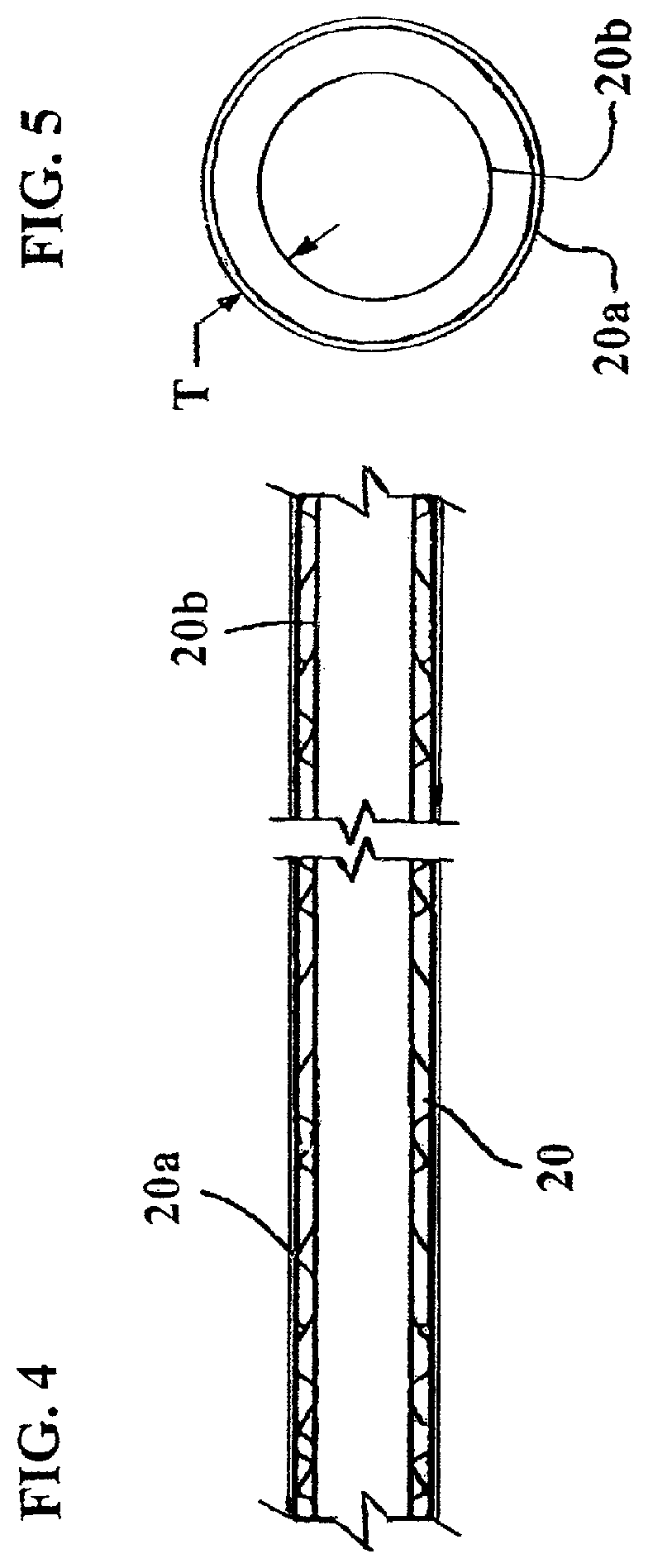
FIG. 4 shows a side cross-sectional view of the catheter and hydrating sleeve used in the assembly package of FIG. 3.
FIG. 5 shows a side cross-sectional view of the hydrating sleeve used in the assembly package of FIG. 3.
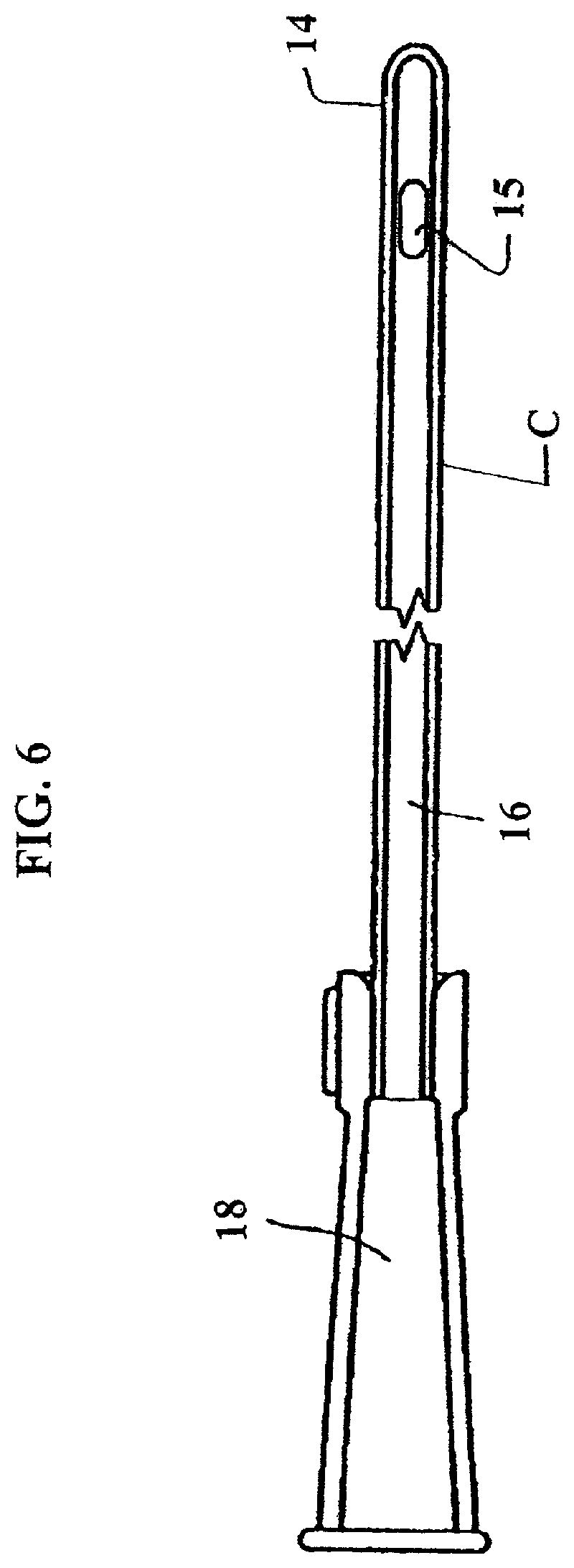
FIG. 6 shows a side cross-sectional view of the catheter used in the assembly package of FIG. 3. In embodiments, the coating can terminate about one inch from the funnel.
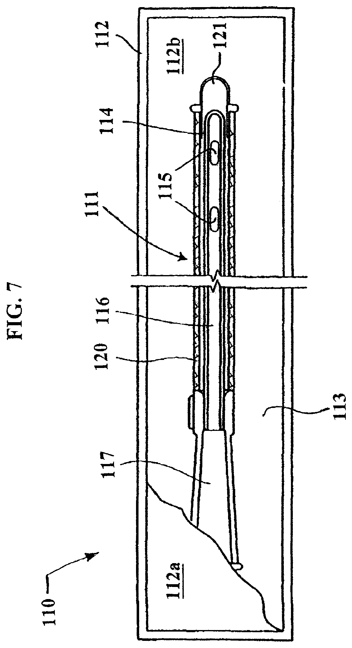
FIG. 7 shows a pre-wetted catheter assembly package in accordance with another non-limiting embodiment of the invention.
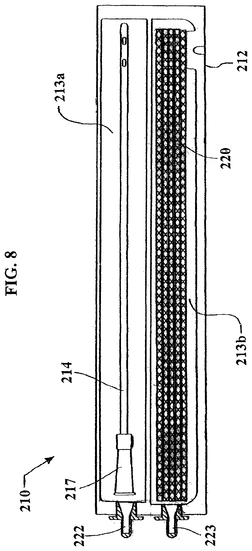
FIG. 8 shows a pre-wetted catheter assembly package in accordance with still another non-limiting embodiment of the invention.
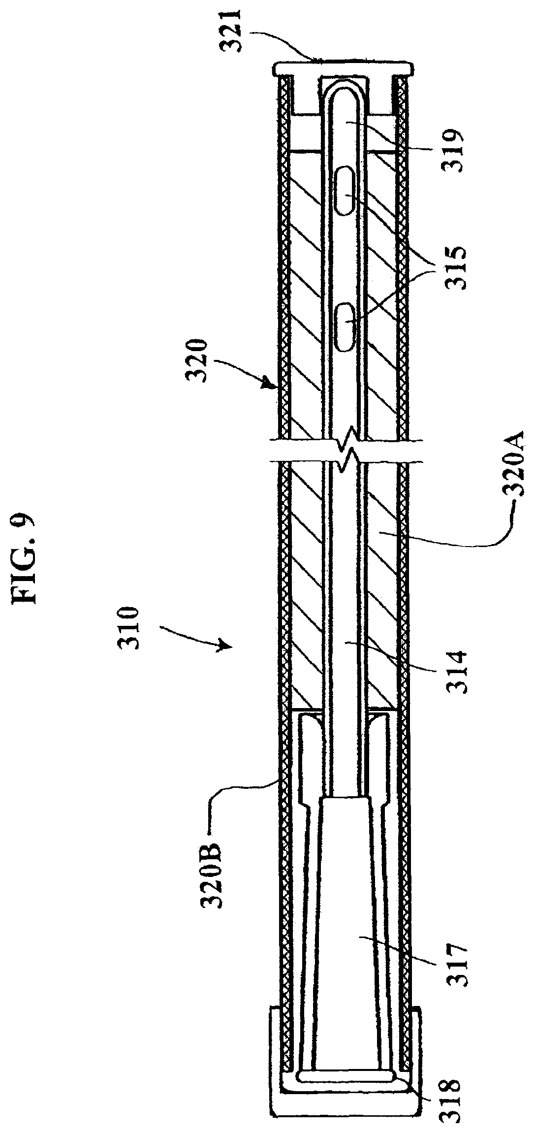
FIG. 9 shows a pre-wetted catheter assembly package in accordance with still another non-limiting embodiment of the invention.
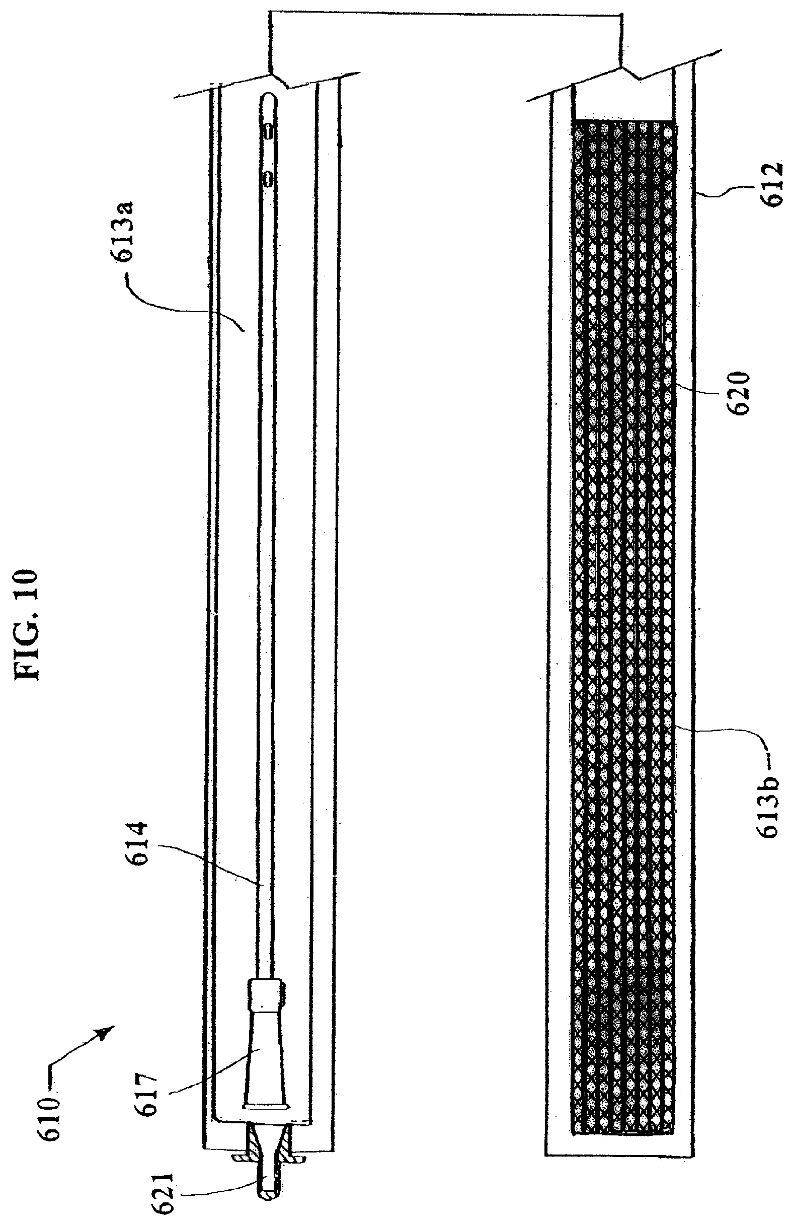
FIGS. 10 and 11 show a pre-wetted catheter assembly package in accordance with still another non-limiting embodiment of the invention.
DETAILED DESCRIPTION OF THE EXEMPLARY EMBODIMENTS
The following description should be read with reference to the drawings, in which like elements in different drawings are identically numbered. The drawings, which are not necessarily to scale, depict selected embodiments and are not intended to limit the scope of the invention. The detailed description illustrates by way of example, not by way of limitation, the principles of the invention. This description will enable one skilled in the art to make and use the invention, and describes several embodiments, adaptations, variations, alternatives and uses of the invention, including what is presently believed to be the best mode of carrying out the invention.
As used herein, the reference terms "proximal" and "distal" (proximal being closer than distal) refer to proximity with respect to a health care professional catheterizing a patient. For example, the region or section of the catheter apparatus that is closest to the health care professional during catheterization is referred to herein as "proximal," while a region or section of the catheter apparatus closest to the patient's bladder is referred to as "distal." In the case of a self-catheterizing patient, proximal refers to a point external to the patient's body, and distal refers to a point within the patient's body (i.e., the bladder).
The catheter assemblies as described herein are discussed in the context of a urinary catheter for insertion into a bladder for drainage of urine therefrom. The instant catheter assemblies, however, may also be used for other applications not specifically mentioned herein. As such, the instant invention is not limited to urinary catheter applications.
FIG. 3 shows a non-limiting embodiment of a pre-wetted urinary catheter assembly package of the present invention. FIG. 3 shows the catheter assembly package in a storage position and/or prior to use configuration.
The assembly package 10 shown in FIG. 3 includes a catheter 11 arranged within a container 12 which can be in the form of a generally flexible material package such as the type shown in FIG. 2. The catheter assembly 11 includes a catheter having an insertable elongate tube portion 14, one or more drainage eyelets 15, a funnel 17, a proximal end 18, and a distal end 19. A fluid containing sleeve 20 is arranged in the package 12 and is positioned over a substantial portion of the tube 14. The sleeve 20 contains all or nearly all of the fluid that is arranged in the container 12 and is in direct contact with a coating of the tube 14. In embodiments, the funnel 17 remains in a dry state in a non-fluid containing space 13 of the package 12. Thus, only the portion of the catheter in contact with the sleeve 20, i.e., all, nearly all, or most of the tube 14, is wetted or maintained in a pre-wetted state. In embodiments, the sleeve 20 is non-removably connected to the package 12 so that when the user tears (e.g., along the dashed-line in space 13) or splits open the end of the package 12 defining space 13, the user can grip the funnel 17 and slide the catheter out of the package 12 and the sleeve 20 (which remains in the package 12). Since all or nearly all of the fluid which hydrates the coating of the tube 14 is disposed in the sleeve 20, removing the catheter will not cause any fluid to spill out of the package 12 when opened. Furthermore, if the sleeve 20 remains in the package 12, the user need not come into contact with the fluid. Once the catheter is removed from the package 12, it can be inserted into the user's body while the user grips the funnel 17. As is the case with conventional catheters, the coating of the tube 14 is, in embodiments, a lubricious coating to facilitate insertion of the catheter into the user's body.
In embodiments, the package 12 is made of foil material which ensures that the catheter assembly 11 and the sleeve 20 are not dehydrated. The package 12 also ensures that its contents are sealed in a gas and/or fluid tight and/or impermeable manner so that hydrating fluid will not leak out. In embodiments, at least an inner layer, i.e., the layer in contact with the sleeve 20, of the package 12 is made of a foil material. In embodiments, the package 12 is made of a single layer foil material. In embodiments, the package 12 is made of plural layers of different materials with at least one layer being a foil material.
In order to form the assembly package of FIG. 3, in embodiments, a catheter of the type shown in, e.g., FIG. 6, can be inserted into a fluid containing sleeve 20 so as to form a sub-assembly. However, prior to insertion into the sleeve 20, the sleeve 20 can be exposed to or immersed in a fluid such as water. Since the sleeve 20 is made of a material that can absorb fluid and expand, this causes the sleeve 20 to swell until it reaches a wall thickness (similar to thickness T in FIG. 5). In this swollen state, the sleeve 20 retains the fluid between an inside diameter and an outside diameter. Once the sleeve 20 is slid onto the catheter, it can maintain the coating of the tube 14 is a hydrated state. This sub-assembly can then be slid into the package 12. Furthermore, since the package 12 is fluid impermeable, it ensures that the fluid in the sleeve 20 cannot escape the package 12 or be contaminated with outside the package 12. In embodiments, the inside diameter of the sleeve 20 is fluid permeable and wets and hydrates the coating of the tube 14 when contacting the tube 14. In embodiments, the outside diameter of the sleeve 20 is also fluid permeable and slightly wets the package 12 when contacting the same. However, unlike the coating of the tube 14, the package 12 does not absorb the fluid. In embodiments, the outside diameter of the sleeve 20 can alternatively be made fluid impermeable so as not to wet the package 12 when contacting the same.
In order to form the assembly package of FIG. 3, in other embodiments, a catheter, e.g., of the type shown in FIG. 6, can be inserted into a fluid containing sleeve 20 after the sleeve 20 is already installed in the package 12. However, prior to insertion into the package 12, the sleeve 20 can be exposed to or immersed in a fluid such as water. Since the sleeve 20 is made of a material that can absorb fluid and expand, this causes the sleeve 20 to swell until it reaches a full or nearly fill fluid swollen wall thickness. In this swollen state, the sleeve 20 retains the fluid between an inside diameter and an outside diameter. Once the catheter is slid into the sleeve 20 already disposed in the package 12, it can maintain the coating of the tube 14 is a hydrated state.
In order to form the assembly package of FIG. 3, in still other embodiments, a catheter, e.g., of the type shown in FIG. 6, can be inserted into a fluid containing sleeve 20 after the sleeve 20 is already installed in the package 12. After insertion into the package 12, the sleeve 20 and package 12 can be exposed to or immersed in a fluid such as water. Since the sleeve 20 is made of a material that can absorb fluid and expand (even while the package 12 cannot absorb fluid), this causes the sleeve 20 to swell until it reaches a swollen wall thickness. In this swollen state, the sleeve 20 retains the fluid between an inside diameter and an outside diameter. Once the catheter is slid into the sleeve 20 disposed in the package 12, the package 12 is sealed closed. The sleeve 20 can then maintain the coating of the tube 14 in a hydrated state while both are inside the package 12.
In still other embodiments, in order to form the assembly package of FIG. 3, a catheter, e.g., of the type shown in FIG. 6, can be inserted into the package 12 after an inner surface of the package 12 is coated with a fluid containing material which, due to the shape of the package 12, can produce a sleeve 20. After or before insertion of the catheter into the package 12, at least the sleeve 20 can be exposed to or immersed in a fluid such as water. Since the sleeve 20 is made of a material that can absorb fluid and expand, this causes the sleeve 20 to swell until it reaches a swollen wall thickness. In this swollen state, the sleeve 20 retains the fluid between an inside diameter and an outside diameter. Once the catheter is slid into the sleeve 20 disposed in the package 12, the package 12 is sealed closed. The sleeve 20 can then maintain the coating of the tube 14 in a hydrated state while both are inside the package 12.
In still other embodiments, the material forming the sleeve 20 can be applied to and/or coated onto the material forming the package 12 so as to form a package having a fluid absorbing and storing inner liner material. In other embodiments, the material forming the sleeve 20 can be co-extruded with the material forming the package 12 so as to form a package having a fluid absorbing and storing inner liner material. In other embodiments, the material forming the sleeve 20 is laminated with the material forming the package 12 so as to form a package having a fluid absorbing and storing inner liner material.
The elongate member 14 can have any size and shape typically utilized in conventional catheters such as generally cylindrical and defines an interior lumen or space which allows fluid to pass and/or drain through. The proximal end 18 includes a funnel which can be of any type that is typically utilized in catheters. The funnel can be connected to any type fluid collection system or bag that is typically utilized in catheters. By way of non-limiting example, the funnel can be a rubber or plastic drainage funnel disposed and friction-fitted on the proximal end of the member 14. A disposable bag (not shown) may be disposed on and/or coupled to the drainage funnel to collect the patient's urine. The distal end 19 of member 14 also includes a tip. The tip is arranged on a forward most portion of the distal end and defines the insertion end of the catheter. The elongate member 14 also preferably contains a biocompatible, hydrophilic, or lubricious coating on its outer surface which is hydrated by the sleeve 20. The coating may also have antimicrobial properties or contain an antimicrobial agent.
FIGS. 4 and 5 show a non-limiting embodiment of a catheter coating hydrating sleeve 20. The sleeve 20 is made of a material that can absorb fluid and expand, this causes the sleeve 20 to swell until it reaches a wall thickness T (see FIG. 5). In this swollen state, the sleeve 20 retains the fluid between an inside diameter 20b and an outside diameter 20a. In embodiments, the sleeve 20 includes an outer generally cylindrically shaped foil layer whose outside diameter defines an outside diameter 20a of the sleeve 20 and an inner generally cylindrical layer of fluid absorbing material which defines an inside diameter 20b of the sleeve 20.
According to another non-limiting embodiment, the hydrating sleeve 20 shown in FIGS. 4 and 5 can be utilized in the type of package 12 shown in FIG. 3.
FIG. 7 shows another non-limiting embodiment of a pre-wetted urinary catheter of the present invention. In FIG. 7, the catheter assembly package is in a storage position and/or prior to use configuration.
The assembly package 110 shown in FIG. 7 includes a catheter 111 arranged within a container 112 which can be in the form of a generally flexible material package similar to that shown in FIG. 2, but somewhat larger to allow (or provide space for) the catheter 111 to more freely move therein. In embodiments, the package 112 can be formed of package sheets 112a and 112b which are connected together in peripheral seam areas. The catheter assembly 111 includes a catheter having an insertable elongate tube portion 114, one or more drainage eyelets 115, a funnel 117 arranged on a proximal end, and a distal end. A fluid containing sleeve 120 is arranged in the package 112, and is positioned over a substantial portion of the tube 114. The sleeve 120 utilizes a gripping portion 121 secured to a forward end of the sleeve 120 which allows the user to grip and remove the sleeve 120 from the catheter. As with the previous embodiments, the sleeve 120 contains all or nearly all of the fluid that is arranged in the container 112, and is in direct contact with a coating of the tube 114. The package can be designed such that, in embodiments, the funnel 117 and gripping portion 121 generally remain in a dry or mostly dry state in a non and/or generally low-fluid containing space 113 of the package 112. Thus, only the portion of the catheter in contact with the sleeve 120, i.e., all, nearly all, or most of the tube 114, is wetted or maintained in a pre-wetted state.
In embodiments, the sleeve 120 is removable from the package 112 with the catheter as assembly 111 when the user tears or splits open one end of the package 112. Once removed from the package 112, the user can grip the funnel 117 with one hand and the gripping portion 121 with the other hand, and then slide the catheter out of the sleeve 120 and/or slide the sleeve 120 off of the catheter 111. Since all or nearly all of the fluid which hydrates the coating of the tube 114 is disposed in the sleeve 120, removing the catheter assembly 111 from the package 112 will not cause any (or hardly any) fluid to spill out of the package 112 when opened. Furthermore, if the sleeve 120 is gripped by the end 121 and placed back into the package 112, the user need not come into contact with the fluid. Once the catheter 111 is removed from the package 112, it can be inserted into the user's body while the user grips the funnel 117. As is the case with conventional catheters, the coating of the tube 114 is, in embodiments, a lubricious coating to facilitate insertion of the catheter into the user's body.
In order to form the assembly package of FIG. 7, in embodiments, a catheter, e.g., of the type shown in FIG. 6, can be inserted into the fluid containing sleeve 120 shown in FIG. 7. However, prior to insertion into the sleeve 120, the sleeve 120 can be exposed to or immersed in a fluid such as water. Since the sleeve 120 is made of a material that can absorb fluid and expand, this causes the sleeve 120 to swell until it reaches a wall thickness (similar to thickness T that shown in FIG. 5). In this swollen state, the sleeve 120 retains the fluid between an inside diameter and an outside diameter. Once the sleeve 120 is slid onto the catheter as shown in FIG. 7, it can maintain the coating of the tube 114 is a hydrated state. This sub-assembly of the catheter 111 and sleeve 120 can then be slid into the package 112. Furthermore, since the package 112 is fluid impermeable, it ensures that the fluid in the sleeve 120 cannot escape the package 112 or be contaminated with outside the package 112. In embodiments, the inside diameter of the sleeve 120 is fluid permeable and wets and hydrates the coating of the tube 114 when contacting the tube 114. In embodiments, the outside diameter of the sleeve 120 is also fluid permeable and slightly wets the package 112 when contacting the same. However, unlike the coating of the tube 114, the package 112 does not absorb the fluid. In embodiments, the outside diameter can alternatively be made fluid impermeable so as not to wet the package 112 when contacting the same.
In embodiments, the package 112 is made of foil material which ensures that the catheter assembly 111 and the sleeve 120 are not contaminated. The package 112 also ensures that its contents are sealed in a gas and/or fluid tight and/or impermeable manner so that hydrating fluid will not leak out. In embodiments, at least an inner layer, i.e., the layer in contact with the sleeve 120, of the package 112 is made of a foil material. In embodiments, the package 112 is made of a single layer foil material. In embodiments, the package 112 is made of plural layers of different materials with at least one layer being a foil material.
According to another non-limiting embodiment, the hydrating sleeve 120 shown in FIG. 7 can utilize a sleeve configuration of the type shown in FIGS. 4 and 5, i.e., the sleeve 120 can have a hydration containing inner sleeve layer and a foil outer layer.
FIG. 8 shows another non-limiting embodiment of a pre-wetted urinary catheter of the present invention. In FIG. 8, the catheter assembly package is in a storage position and/or prior to use configuration.
The assembly package 210 shown in FIG. 8 includes a catheter arranged within a first compartment 213a of a container 212 which can be in the form of a generally flexible package similar to the type shown in FIG. 2. A fluid containing sleeve 220 is arranged within a second compartment 213b of the container 212. The catheter has an insertable elongate tube portion 214, one or more drainage eyelets, a funnel 217 arranged on a proximal end, and a distal end. The fluid containing sleeve 220 is sized to be positioned over and onto a substantial portion of the tube 214. When the user desires to use the catheter, the user removes sealing covers 222 and 223. Next, the user removes the catheter from the compartment 213a. The user then inserts the catheter into the compartment 213b making sure to insert the tube 214 into the lumen of the sleeve 220. After fully inserting the tube 214 into the sleeve 220 and waiting for a short predetermined time period, i.e., a few seconds to a few minutes (a time period sufficient to allow the coating of the tube 214 to become sufficiently hydrated and/or pre-wetted), the user can remove the catheter from the compartment 213b (while the sleeve 220 remains in the compartment 213b) and then insert the same into the user's (or another user's) body.
As with the previous embodiment, the sleeve 220 contains all or nearly all of the fluid that is arranged in the container 212 and can be placed in direct contact with a coating of the tube 214. The funnel 217 can remain in a dry state in a non-fluid containing space 213a of the package 212.
In embodiments, the package 212 is made of foil material which ensures that the catheter assembly and the sleeve 220 are not contaminated. The package 212 also ensures that its contents are sealed in a gas and/or fluid tight and/or impermeable manner so that hydrating fluid will not leak out. In embodiments, at least an inner layer, i.e., the layer in contact with the sleeve 220, of the package 212 is made of a foil material. In embodiments, the package 212 is made of a single layer foil material. In embodiments, the package 212 is made of plural layers of different materials with at least one layer being a foil material.
In embodiments, the caps 222 and 223 are optional. These can, in embodiments, can be formed by sealing the ends of the package (after inserting the catheter members into the package). These ends can then be torn or pealed open. Such an alternative configuration to the caps 222 and 223 would likely be cheaper to manufacture.
In still other embodiments, the material forming the sleeve 220 can be applied to and/or coated onto the material forming the compartment 213b of the package 212 so as to form a package compartment having a fluid absorbing and storing inner liner material. In other embodiments, the material forming the sleeve 220 can be co-extruded with the material forming the compartment 213b of the package 212 so as to form a package having a fluid absorbing and storing inner liner material in compartment 213b. In other embodiments, the material forming the sleeve 220 is laminated with the material forming the compartment 213b of the package 212 so as to form a package compartment 213b having a fluid absorbing and storing inner liner material.
In order to form the assembly package of FIG. 8, in embodiments, a catheter, e.g., of the type shown in FIG. 6, can be inserted into compartment 213a shown in FIG. 8 and then the cap 222 can be installed. A sleeve 220 can be inserted into compartment 213b shown in FIG. 8 and then the cap 223 can be installed. However, prior to installation of the cap 223, the sleeve 220 can be exposed to or immersed in a fluid such as water (which can be poured into the chamber 213b). Since the sleeve 220 is made of a material that can absorb fluid and expand, this causes the sleeve 220 to swell until it reaches a swollen wall thickness. In this swollen state, the sleeve 220 retains the fluid between an inside diameter and an outside diameter. Once the catheter is slid into the sleeve 220 located in the compartment 213b, it can sufficiently hydrate the coating of the tube 214 (after a predetermined amount of time). Furthermore, since the package 212 is fluid impermeable (especially compartment 213b), it ensures that the fluid in the sleeve 220 cannot escape the package 212 or be contaminated with outside the package 212.
In embodiments, the inside diameter of the sleeve 220 is fluid permeable and wets and hydrates the coating of the tube 214 when contacting the tube 214. In embodiments, the outside diameter of the sleeve 220 is also fluid permeable and slightly wets the package 212 when contacting the same. However, unlike the coating of the tube 214, the package 212 does not absorb the fluid. In embodiments, the outside diameter of the sleeve 220 can alternatively and/or additionally be made fluid impermeable so as not to wet the package 212 when contacting the same.
According to another non-limiting embodiment, the hydrating sleeve 220 shown in FIG. 8 can utilize a sleeve configuration of the type shown in FIGS. 4 and 5, i.e., the sleeve 220 can have a hydration containing inner sleeve layer and a foil outer layer.
FIG. 9 shows another non-limiting embodiment of a pre-wetted urinary catheter assembly package of the present invention. In FIG. 9, the catheter assembly package is in a storage position and/or prior to use configuration.
The assembly package 310 shown in FIG. 9 includes a catheter assembly arranged within a container which is in the form of an outer sleeve 320B and end cap 321 affixed thereto. An alternative sealing device can also be utilized instead of the end cap 321. The catheter assembly includes a catheter having an insertable elongate tube portion 314, one or more drainage eyelets 315, a funnel 317, a proximal end 318, and a distal end 319. A fluid containing sleeve 320A is arranged in the package sleeve 320B and is positioned over a substantial portion of the tube 314. The sleeve 320A contains all or nearly all of the fluid that is arranged in the container 320B, and is in direct contact with a coating of the tube 314. The funnel 317 remains in a dry state in a non and/or low-fluid containing space of the package 320B. Thus, only the portion of the catheter in contact with the sleeve 320A, i.e., all, nearly all, or most of the tube 314, is wetted or maintained in a pre-wetted state. In embodiments, the sleeve 320A is not non-removably connected to the outer sleeve 320B. In other embodiments, the sleeve 320A may be non-removably connected to the outer sleeve 320B. In this way, the user can slide off the sleeve 320A when the user removes the cap 318, then grips the funnel 317 with one hand and the sleeve 320B with the other hand, and then slides the catheter out of the package 320B (the sleeve 320A remains in the package 320B). Since all or nearly all of the fluid which hydrates the coating of the tube 314 is disposed in the sleeve 320A, removing the catheter will not cause any fluid to spill out of the package 320B when opened. Furthermore, as the sleeve 320A remains in the package 320B, the user need not come into contact with the fluid. Once the catheter is removed from the package 320B, it can be inserted into the user's body while the user grips the funnel 317. As is the case with conventional catheters, the coating of the tube 314 is, in embodiments, a lubricious coating to facilitate insertion of the catheter into the user's body.
In order to form the assembly package of FIG. 9, in embodiments, a catheter, e.g., of the type shown in FIG. 6, can be inserted into a fluid containing sleeve 320A shown in FIG. 9 which is already arranged within an outer sleeve 320B. Prior to or after insertion of the sleeve 320A into the sleeve 320B, the sleeve 320A can be exposed to or immersed in a fluid such as water. Since the sleeve 320A is made of a material that can absorb fluid and expand, this causes the sleeve 320A to swell until it reaches a swollen wall thickness. In this swollen state, the sleeve 320A retains the fluid between an inside diameter and an outside diameter. Once the catheter is slid into the sleeve 320A, it can maintain the coating of the tube 314 is a hydrated state. Alternatively, the sleeve 320A can be slid onto the catheter tube 314 and then exposed to a hydrating fluid. This sub-assembly can then be slid into the sleeve package 320B.
Since the sleeve package 320B is fluid impermeable, it ensures that the fluid in the sleeve 320A cannot escape the package 320B or be contaminated with outside the package. In embodiments, the inside diameter of the sleeve 320A is fluid permeable and wets and hydrates the coating of the tube 314 when contacting the tube 314. In embodiments, the outside diameter of the sleeve 320A is also fluid permeable and slightly wets the sleeve package 320B when contacting the same. However, unlike the coating of the tube 314, the package 320B does not absorb the fluid. In embodiments, the outside diameter can alternatively be made fluid impermeable so as not to wet the package 320B when contacting the same. A removable cap 318 is arranged on one end of the sleeve 320B in order to prevent contact with the funnel 317 and to seal off the distal end of the sleeve package 320B.
In embodiments, the package 312B is made of foil material for protecting the catheter assembly and the sleeve 320A. The foil functions as a moisture barrier to prevent evaporation of water from the fluid hydrating the sleeve through the package and properly seals the same within the package. The package 312B (when its ends are covered with caps 318 and 321 or otherwise sealed) also ensures that its contents are enclosed in a gas and/or fluid tight and/or impermeable manner so that hydrating fluid will not leak out. In embodiments, at least an inner layer, i.e., the layer in contact with the sleeve 320, of the package 312B is made of a foil material. In embodiments, the package 312B is made of a single layer foil material. In embodiments, the package 312B is made of plural layers of different materials with at least one layer being a foil material.
According to another non-limiting embodiment, the hydrating sleeve 320A shown in FIG. 9 can utilize a sleeve configuration of the type shown in FIGS. 4 and 5, i.e., the sleeve 320A can have a hydration containing inner sleeve layer and a foil outer layer which may or may not be secured to an inner cylindrical surface of the sleeve 320B.
FIGS. 10 and 11 show another non-limiting embodiment of a pre-wetted urinary catheter of the present invention. FIG. 10 shows the catheter assembly package in a storage position and/or prior to use configuration. FIG. 11 shows the catheter assembly package in a position just prior to use.
The assembly package 610 shown in FIG. 11 includes a catheter arranged within a first compartment 613a of a flexible container 612 which can be in the form of a package such as the type shown in FIG. 2, but having a more elongate configuration. A fluid containing inner layer (or sleeve) 620 is arranged within a second compartment 613b of the container 612. The catheter has an insertable elongate tube portion 614, one or more drainage eyelets, a funnel 617 arranged on a proximal end, and a distal end. The fluid containing sleeve 620 is sized to be positioned over a substantial portion of the tube 614. When the user desires to use the catheter, the user manipulates the package 610 so that the catheter can be inserted into the sleeve 620 (see FIG. 11). Then, he can remove sealing cover or cap 621 (or otherwise unseal an end of the package) and remove the catheter from the compartment 613a. However, before the catheter is removed from the package 612, the tube 614 must be fully inserted into the sleeve 620 for a short predetermined time period (and retained in the configuration shown in FIG. 11). This time period can be, e.g., a few seconds to a few minutes and is, in embodiments, a time period sufficient to allow the coating of the tube 614 to become sufficiently hydrated and/or pre-wetted. As with the previous embodiment, the sleeve 620 contains all or nearly all of the fluid that is arranged in the container 612 and can be placed in direct contact with a coating of the tube 614. Prior to use, the funnel 617 and tube 614 remains in a dry state in a non-fluid containing space 613a of the package 612 (as shown in FIG. 10). Thus, catheter is not maintained in a pre-wetted state until it assumes the position shown in FIG. 11. In embodiments, the inner layer or sleeve 620 is not removable from the package 612 with the catheter and/or is secured or affixed to an inner surface of the package 612. Alternatively, it is possible to seal the package 612 between portion 613a and portion 613b with, e.g., a light "V" seal. The user could then push the member 614 through the seal into portion 613b having the hydration sleeve or material 620. Once removed from the package 612, the user can grip the funnel 617 with one hand and the package 612 with the other hand, and then slide the catheter out of the compartment 613a. Since all or nearly all of the fluid which hydrates the coating of the tube 614 is disposed in the inner layer or sleeve 620, removing the catheter assembly from the package 612 will not cause any fluid to spill out of the package 612 when opened. Furthermore, if the sleeve 620 is gripped from outside the package 612 and is retained in the compartment 613b, the user need not come into contact with the fluid. Once the catheter is properly hydrated while in the package 612, it can be removed therefrom and inserted into the user's body while the user grips the funnel 617. As is the case with conventional catheters, the coating of the tube 614 is, in embodiments, a lubricious coating to facilitate insertion of the catheter into the user's body.
In order to form the assembly package of FIG. 10, in embodiments, an inner material or sleeve 620 can be inserted into compartment 613b shown in FIG. 10, then a catheter can be inserted into compartment 613a shown in FIG. 10. Then, the cap 621 can be installed or alternatively the package can be otherwise sealed. However, prior to insertion into the package 612, the sleeve 620 can be exposed to or immersed in a fluid such as water. Since the sleeve 620 is made of a material that can absorb fluid and expand, this causes the sleeve 620 to swell until it reaches a swollen wall thickness. In this swollen state, the sleeve 620 retains the fluid between an inside diameter and an outside diameter. Once the catheter is slid into the sleeve 620 (as shown in FIG. 11), it can hydrate the coating of the tube 614. Furthermore, since the package 612 is fluid impermeable, it ensures that the fluid in the sleeve 620 cannot escape the package 612 or be contaminated with outside the package 612. In embodiments, the inside diameter (if and when the material 620 is deformed into a circular shape) of the sleeve 620 is fluid permeable and wets and hydrates the coating of the tube 614 when contacting the tube 614. In embodiments, the outside diameter of the sleeve 620 is also fluid permeable and slightly wets the package 612 when contacting the same. However, unlike the coating of the tube 614, the package 612 does not absorb the fluid. In embodiments, the outside diameter can alternatively be made fluid impermeable so as not to wet the package 612 when contacting the same.
In embodiments, the package 612 is made of foil material which ensures that the catheter assembly and the sleeve 620 are not contaminated. The package 612 (when it end is covered with cap 621) also ensures that its contents are sealed in a gas and/or fluid tight and/or impermeable manner so that hydrating fluid will not leak out. In embodiments, at least an inner layer, i.e., the layer in contact with the sleeve 620, of the package 612 is made of a foil material. In embodiments, the package 612 is made of a single layer foil material. In embodiments, the package 612 is made of plural layers of different materials with at least one layer being a foil material.
According to another non-limiting embodiment, the hydrating material or sleeve 620 shown in FIG. 10 can utilize a sleeve configuration of the type shown in FIGS. 4 and 5, i.e., the material or sleeve 620 can have a hydration containing inner sleeve layer and a foil outer layer which may or may not be secured to an inner surface of the package 612.
In each of the herein disclosed embodiments, the fluid containing member or sleeve may, in embodiments, be a hydrogel sleeve. In embodiments, the fluid containing member may also have at least one of the following: a wall thickness T that is 1/16 inch or greater, e.g., 1/8 inch, (in a fully hydrated condition); may be generally cylindrical; may also be structured and arranged to maintain a coating of the elongate member in a hydrated condition; may be a tube having an inside diameter sized to receive therein the elongate member; may comprise an extruded polyurethane tube; may comprise one or more materials described above; may comprise a material which swells when exposed to a fluid and which absorbs and retains fluid in a wall between an inner diameter and an outer diameter; may be structured and arranged to swell when exposed to a fluid; may be structured and arranged to swell when exposed to water; may be structured and arranged, in embodiments, to absorb about 90% of its weight in fluid; may be structured and arranged to absorb about 90% of its weight in water; and may comprise a hydrated polyurethane tube.
The catheter insertion tube member and hydrating sleeve may have a round cross-sectional shape, an oval cross-sectional shape, or any other cross-sectional shape that may facilitate insertion into the body of a user/patient, and, in particular, into the bladder of the user/patient through the urethra. The catheter insertion member in accordance with various embodiments) can preferably contain a biocompatible hydrophilic coating on at least an outer surface thereof. The coating may also have antimicrobial properties and/or contain antimicrobial agents. Suitable non-limiting examples of such lubricious and antimicrobial coatings are disclosed in U.S. Pat. Nos. 4,585,666; 5,558,900; 5,077,352; 5,179,174; 6,329,488 (suitable for, e.g., polysiloxane substrates); U.S. Pat. Nos. 6,716,895; 6,949,598; and 7,179,849, and WO 2007/050685, each of which is incorporated by reference in its entirety.
The antimicrobial agent used on the catheter may be one listed in an over the counter (OTC) monograph. Biocompatible coatings conform with the following tests: mucosal irritation, sensitization, cytotoxicity, acute systemic toxicity, and implantation. ("Tripartite Biocompatibility Guidance for Medical Devices," DSMA (Apr. 24, 1987) (Updated May 21, 1996)). The purpose of the wetting fluid is to maintain hydration of the lubricious coating such that upon insertion of the conduit into a user, at least an outer portion thereof is extremely slippery, facilitating insertion.
The catheter insertion member may preferably be constructed from a suitable polymeric material, such as polyvinyl chloride (PVC), silicone, latex or other synthetic rubber. The components of the catheter disclosed
D00000
D00001
D00002
D00003
D00004
D00005
D00006
D00007
D00008
D00009
D00010
XML
uspto.report is an independent third-party trademark research tool that is not affiliated, endorsed, or sponsored by the United States Patent and Trademark Office (USPTO) or any other governmental organization. The information provided by uspto.report is based on publicly available data at the time of writing and is intended for informational purposes only.
While we strive to provide accurate and up-to-date information, we do not guarantee the accuracy, completeness, reliability, or suitability of the information displayed on this site. The use of this site is at your own risk. Any reliance you place on such information is therefore strictly at your own risk.
All official trademark data, including owner information, should be verified by visiting the official USPTO website at www.uspto.gov. This site is not intended to replace professional legal advice and should not be used as a substitute for consulting with a legal professional who is knowledgeable about trademark law.