Smart battery balance system and method
Zhang , et al.
U.S. patent number 10,698,470 [Application Number 15/829,167] was granted by the patent office on 2020-06-30 for smart battery balance system and method. This patent grant is currently assigned to HAND HELD PRODUCTS, INC.. The grantee listed for this patent is Hand Held Products, Inc.. Invention is credited to Chao Cao, Jinhua Shen, Jinchao Shi, Zhenjun Zhang.
| United States Patent | 10,698,470 |
| Zhang , et al. | June 30, 2020 |
Smart battery balance system and method
Abstract
A smart battery power balance system and method to maximize the operating life of a mobile computing device and a portable peripheral (e.g., a peripheral having scanning capability). The mobile computing device battery and portable peripheral battery parameters such as battery level, velocity/rate of consumption and usage history are collected. A curve fitting and estimation is done to predict the empty time for complete battery discharge of the mobile computing device and portable peripheral. Based on this analysis, if the calculated empty time of the mobile computing device battery is less than the portable peripheral battery, the portable peripheral charges the mobile computing device battery and if the calculated empty time of the mobile computing device battery is greater than that of the portable peripheral battery, the portable peripheral battery does not charge the mobile computing battery.
| Inventors: | Zhang; Zhenjun (Jiangsu, CN), Cao; Chao (Jiangsu, CN), Shen; Jinhua (Jiangsu, CN), Shi; Jinchao (Jiangsu, CN) | ||||||||||
|---|---|---|---|---|---|---|---|---|---|---|---|
| Applicant: |
|
||||||||||
| Assignee: | HAND HELD PRODUCTS, INC. (Fort
Mill, SC) |
||||||||||
| Family ID: | 62487971 | ||||||||||
| Appl. No.: | 15/829,167 | ||||||||||
| Filed: | December 1, 2017 |
Prior Publication Data
| Document Identifier | Publication Date | |
|---|---|---|
| US 20180164867 A1 | Jun 14, 2018 | |
Foreign Application Priority Data
| Dec 9, 2016 [CN] | 2016 1 1130208 | |||
| Current U.S. Class: | 1/1 |
| Current CPC Class: | H02J 7/0021 (20130101); H02J 7/0014 (20130101); H02J 7/0047 (20130101); G06F 1/1632 (20130101); G06F 1/266 (20130101); G06F 1/3287 (20130101); H02J 7/342 (20200101); G06F 1/263 (20130101); G06F 1/3212 (20130101); G06F 2200/1633 (20130101); H02J 7/00 (20130101); H02J 7/0048 (20200101) |
| Current International Class: | G06F 1/3212 (20190101); H02J 7/00 (20060101); G06F 1/26 (20060101); G06F 1/3287 (20190101); H02J 7/34 (20060101); G06F 1/16 (20060101) |
| Field of Search: | ;320/118,106 |
References Cited [Referenced By]
U.S. Patent Documents
| 5461717 | October 1995 | Notarianni |
| 5666066 | September 1997 | Townsley et al. |
| 6832725 | December 2004 | Gardiner et al. |
| 7128266 | October 2006 | Zhu et al. |
| 7159783 | January 2007 | Walczyk et al. |
| 7413127 | August 2008 | Ehrhart et al. |
| 7726575 | June 2010 | Wang et al. |
| 8001419 | August 2011 | Killian |
| 8294969 | October 2012 | Plesko |
| 8317105 | November 2012 | Kotlarsky et al. |
| 8322622 | December 2012 | Liu |
| 8366005 | February 2013 | Kotlarsky et al. |
| 8371507 | February 2013 | Haggerty et al. |
| 8376233 | February 2013 | Horn et al. |
| 8381979 | February 2013 | Franz |
| 8390909 | March 2013 | Plesko |
| 8408464 | April 2013 | Zhu et al. |
| 8408468 | April 2013 | Horn et al. |
| 8408469 | April 2013 | Good |
| 8424768 | April 2013 | Rueblinger et al. |
| 8448863 | May 2013 | Xian et al. |
| 8457013 | June 2013 | Essinger et al. |
| 8459557 | June 2013 | Havens et al. |
| 8469272 | June 2013 | Kearney |
| 8474712 | July 2013 | Kearney et al. |
| 8479992 | July 2013 | Kotlarsky et al. |
| 8490877 | July 2013 | Kearney |
| 8517271 | August 2013 | Kotlarsky et al. |
| 8523076 | September 2013 | Good |
| 8528818 | September 2013 | Ehrhart et al. |
| 8544737 | October 2013 | Gomez et al. |
| 8548420 | October 2013 | Grunow et al. |
| 8550335 | October 2013 | Samek et al. |
| 8550354 | October 2013 | Gannon et al. |
| 8550357 | October 2013 | Kearney |
| 8556174 | October 2013 | Kosecki et al. |
| 8556176 | October 2013 | Van Horn et al. |
| 8556177 | October 2013 | Hussey et al. |
| 8559767 | October 2013 | Barber et al. |
| 8561895 | October 2013 | Gomez et al. |
| 8561903 | October 2013 | Sauerwein |
| 8561905 | October 2013 | Edmonds et al. |
| 8565107 | October 2013 | Pease et al. |
| 8571307 | October 2013 | Li et al. |
| 8579200 | November 2013 | Samek et al. |
| 8583924 | November 2013 | Caballero et al. |
| 8583955 | November 2013 | Lu et al. |
| 8584945 | November 2013 | Wang et al. |
| 8587595 | November 2013 | Wang |
| 8587697 | November 2013 | Hussey et al. |
| 8588869 | November 2013 | Sauerwein et al. |
| 8590789 | November 2013 | Nahill et al. |
| 8596539 | December 2013 | Havens et al. |
| 8596542 | December 2013 | Havens et al. |
| 8596543 | December 2013 | Havens et al. |
| 8599271 | December 2013 | Havens et al. |
| 8599957 | December 2013 | Peake et al. |
| 8600158 | December 2013 | Li et al. |
| 8600167 | December 2013 | Showering |
| 8602309 | December 2013 | Longacre et al. |
| 8608053 | December 2013 | Meier et al. |
| 8608071 | December 2013 | Liu et al. |
| 8611309 | December 2013 | Wang et al. |
| 8615487 | December 2013 | Gomez et al. |
| 8621123 | December 2013 | Caballero |
| 8622303 | January 2014 | Meier et al. |
| 8628013 | January 2014 | Ding |
| 8628015 | January 2014 | Wang et al. |
| 8628016 | January 2014 | Winegar |
| 8629926 | January 2014 | Wang |
| 8630491 | January 2014 | Longacre et al. |
| 8635309 | January 2014 | Berthiaume et al. |
| 8636200 | January 2014 | Kearney |
| 8636212 | January 2014 | Nahill et al. |
| 8636215 | January 2014 | Ding et al. |
| 8636224 | January 2014 | Wang |
| 8638806 | January 2014 | Wang et al. |
| 8640958 | February 2014 | Lu et al. |
| 8640960 | February 2014 | Wang et al. |
| 8643717 | February 2014 | Li et al. |
| 8646692 | February 2014 | Meier et al. |
| 8646694 | February 2014 | Wang et al. |
| 8657200 | February 2014 | Ren et al. |
| 8659397 | February 2014 | Vargo et al. |
| 8668149 | March 2014 | Good |
| 8678285 | March 2014 | Kearney |
| 8678286 | March 2014 | Smith et al. |
| 8682077 | March 2014 | Longacre |
| D702237 | April 2014 | Oberpriller et al. |
| 8687282 | April 2014 | Feng et al. |
| 8692927 | April 2014 | Pease et al. |
| 8695880 | April 2014 | Bremer et al. |
| 8698949 | April 2014 | Grunow et al. |
| 8702000 | April 2014 | Barber et al. |
| 8717494 | May 2014 | Gannon |
| 8720783 | May 2014 | Biss et al. |
| 8723804 | May 2014 | Fletcher et al. |
| 8723904 | May 2014 | Marty et al. |
| 8727223 | May 2014 | Wang |
| 8740082 | June 2014 | Wilz |
| 8740085 | June 2014 | Furlong et al. |
| 8746563 | June 2014 | Hennick et al. |
| 8750445 | June 2014 | Peake et al. |
| 8752766 | June 2014 | Xian et al. |
| 8756059 | June 2014 | Braho et al. |
| 8757495 | June 2014 | Qu et al. |
| 8760563 | June 2014 | Koziol et al. |
| 8763909 | July 2014 | Reed et al. |
| 8777108 | July 2014 | Coyle |
| 8777109 | July 2014 | Oberpriller et al. |
| 8779898 | July 2014 | Havens et al. |
| 8781520 | July 2014 | Payne et al. |
| 8783573 | July 2014 | Havens et al. |
| 8789757 | July 2014 | Barten |
| 8789758 | July 2014 | Hawley et al. |
| 8789759 | July 2014 | Xian et al. |
| 8794520 | August 2014 | Wang et al. |
| 8794522 | August 2014 | Ehrhart |
| 8794525 | August 2014 | Amundsen et al. |
| 8794526 | August 2014 | Wang et al. |
| 8798367 | August 2014 | Ellis |
| 8807431 | August 2014 | Wang et al. |
| 8807432 | August 2014 | Van Horn et al. |
| 8820630 | September 2014 | Qu et al. |
| 8822848 | September 2014 | Meagher |
| 8824692 | September 2014 | Sheerin et al. |
| 8824696 | September 2014 | Braho |
| 8842849 | September 2014 | Wahl et al. |
| 8844817 | September 2014 | Glanzer et al. |
| 8844822 | September 2014 | Kotlarsky et al. |
| 8844823 | September 2014 | Fritz et al. |
| 8849019 | September 2014 | Li et al. |
| D716285 | October 2014 | Chaney et al. |
| 8851383 | October 2014 | Yeakley et al. |
| 8854633 | October 2014 | Laffargue |
| 8866963 | October 2014 | Grunow et al. |
| 8868421 | October 2014 | Braho et al. |
| 8868519 | October 2014 | Maloy et al. |
| 8868802 | October 2014 | Barten |
| 8868803 | October 2014 | Caballero |
| 8870074 | October 2014 | Gannon |
| 8879639 | November 2014 | Sauerwein |
| 8880426 | November 2014 | Smith |
| 8881983 | November 2014 | Havens et al. |
| 8881987 | November 2014 | Wang |
| 8903172 | December 2014 | Smith |
| 8908995 | December 2014 | Benos et al. |
| 8910870 | December 2014 | Li et al. |
| 8910875 | December 2014 | Ren et al. |
| 8914290 | December 2014 | Hendrickson et al. |
| 8914788 | December 2014 | Pettinelli et al. |
| 8915439 | December 2014 | Feng et al. |
| 8915444 | December 2014 | Havens et al. |
| 8916789 | December 2014 | Woodburn |
| 8918250 | December 2014 | Hollifield |
| 8918564 | December 2014 | Caballero |
| 8925818 | January 2015 | Kosecki et al. |
| 8939374 | January 2015 | Jovanovski et al. |
| 8942480 | January 2015 | Ellis |
| 8944313 | February 2015 | Williams et al. |
| 8944327 | February 2015 | Meier et al. |
| 8944332 | February 2015 | Harding et al. |
| 8950678 | February 2015 | Germaine et al. |
| D723560 | March 2015 | Zhou et al. |
| 8967468 | March 2015 | Gomez et al. |
| 8971346 | March 2015 | Sevier |
| 8976030 | March 2015 | Cunningham et al. |
| 8976368 | March 2015 | Akel et al. |
| 8978981 | March 2015 | Guan |
| 8978983 | March 2015 | Bremer et al. |
| 8978984 | March 2015 | Hennick et al. |
| 8985456 | March 2015 | Zhu et al. |
| 8985457 | March 2015 | Soule et al. |
| 8985459 | March 2015 | Kearney et al. |
| 8985461 | March 2015 | Gelay et al. |
| 8988578 | March 2015 | Showering |
| 8988590 | March 2015 | Gillet et al. |
| 8991704 | March 2015 | Hopper et al. |
| 8996194 | March 2015 | Davis et al. |
| 8996384 | March 2015 | Funyak et al. |
| 8998091 | April 2015 | Edmonds et al. |
| 9002641 | April 2015 | Showering |
| 9007368 | April 2015 | Laffargue et al. |
| 9010641 | April 2015 | Qu et al. |
| 9015513 | April 2015 | Murawski et al. |
| 9016576 | April 2015 | Brady et al. |
| D730357 | May 2015 | Fitch et al. |
| 9022288 | May 2015 | Nahill et al. |
| 9026187 | May 2015 | Huang |
| 9030964 | May 2015 | Essinger et al. |
| 9033240 | May 2015 | Smith et al. |
| 9033242 | May 2015 | Gillet et al. |
| 9036054 | May 2015 | Koziol et al. |
| 9037344 | May 2015 | Chamberlin |
| 9038911 | May 2015 | Xian et al. |
| 9038915 | May 2015 | Smith |
| D730901 | June 2015 | Oberpriller et al. |
| D730902 | June 2015 | Fitch et al. |
| D733112 | June 2015 | Chaney et al. |
| 9047098 | June 2015 | Barten |
| 9047359 | June 2015 | Caballero et al. |
| 9047420 | June 2015 | Caballero |
| 9047525 | June 2015 | Barber |
| 9047531 | June 2015 | Showering et al. |
| 9049640 | June 2015 | Wang et al. |
| 9053055 | June 2015 | Caballero |
| 9053378 | June 2015 | Hou et al. |
| 9053380 | June 2015 | Xian et al. |
| 9057641 | June 2015 | Amundsen et al. |
| 9058526 | June 2015 | Powilleit |
| 9061527 | June 2015 | Tobin et al. |
| 9064165 | June 2015 | Havens et al. |
| 9064167 | June 2015 | Xian et al. |
| 9064168 | June 2015 | Todeschini et al. |
| 9064254 | June 2015 | Todeschini et al. |
| 9066032 | June 2015 | Wang |
| 9070032 | June 2015 | Corcoran |
| D734339 | July 2015 | Zhou et al. |
| D734751 | July 2015 | Oberpriller et al. |
| 9076459 | July 2015 | Braho et al. |
| 9079423 | July 2015 | Bouverie et al. |
| 9080856 | July 2015 | Laffargue |
| 9082023 | July 2015 | Feng et al. |
| 9084032 | July 2015 | Rautiola et al. |
| 9087250 | July 2015 | Coyle |
| 9092681 | July 2015 | Havens et al. |
| 9092682 | July 2015 | Wilz et al. |
| 9092683 | July 2015 | Koziol et al. |
| 9093141 | July 2015 | Liu |
| 9098763 | August 2015 | Lu et al. |
| 9104929 | August 2015 | Todeschini |
| 9104934 | August 2015 | Li et al. |
| 9107484 | August 2015 | Chaney |
| 9111159 | August 2015 | Liu et al. |
| 9111166 | August 2015 | Cunningham |
| 9135483 | September 2015 | Liu et al. |
| 9137009 | September 2015 | Gardiner |
| 9141839 | September 2015 | Xian et al. |
| 9147096 | September 2015 | Wang |
| 9148474 | September 2015 | Skvoretz |
| 9158000 | October 2015 | Sauerwein |
| 9158340 | October 2015 | Reed et al. |
| 9158953 | October 2015 | Gillet et al. |
| 9159059 | October 2015 | Daddabbo et al. |
| 9165174 | October 2015 | Huck |
| 9171543 | October 2015 | Emerick et al. |
| 9183425 | November 2015 | Wang |
| 9189669 | November 2015 | Zhu et al. |
| 9195844 | November 2015 | Todeschini et al. |
| 9202458 | December 2015 | Braho et al. |
| 9208366 | December 2015 | Liu |
| 9208367 | December 2015 | Wang |
| 9219836 | December 2015 | Bouverie et al. |
| 9224022 | December 2015 | Ackley et al. |
| 9224024 | December 2015 | Bremer et al. |
| 9224027 | December 2015 | Van Horn et al. |
| D747321 | January 2016 | London et al. |
| 9230140 | January 2016 | Ackley |
| 9235553 | January 2016 | Fitch et al. |
| 9237211 | January 2016 | Tabe |
| 9239950 | January 2016 | Fletcher |
| 9245492 | January 2016 | Ackley et al. |
| 9443123 | January 2016 | Hejl |
| 9248640 | February 2016 | Heng |
| 9250652 | February 2016 | London et al. |
| 9250712 | February 2016 | Todeschini |
| 9251411 | February 2016 | Todeschini |
| 9258033 | February 2016 | Showering |
| 9261398 | February 2016 | Amundsen et al. |
| 9262633 | February 2016 | Todeschini et al. |
| 9262660 | February 2016 | Lu et al. |
| 9262662 | February 2016 | Chen |
| 9262664 | February 2016 | Soule et al. |
| 9269036 | February 2016 | Bremer |
| 9270782 | February 2016 | Hala et al. |
| 9274806 | March 2016 | Barten |
| 9274812 | March 2016 | Doren et al. |
| 9275388 | March 2016 | Havens et al. |
| 9277668 | March 2016 | Feng et al. |
| 9280693 | March 2016 | Feng et al. |
| 9282501 | March 2016 | Wang et al. |
| 9286496 | March 2016 | Smith |
| 9292969 | March 2016 | Laffargue et al. |
| 9297900 | March 2016 | Jiang |
| 9298667 | March 2016 | Caballero |
| 9298964 | March 2016 | Li et al. |
| 9301427 | March 2016 | Feng et al. |
| 9304376 | April 2016 | Anderson |
| 9310609 | April 2016 | Rueblinger et al. |
| 9313377 | April 2016 | Todeschini et al. |
| 9317037 | April 2016 | Byford et al. |
| 9319548 | April 2016 | Showering et al. |
| D757009 | May 2016 | Oberpriller et al. |
| 9342723 | May 2016 | Liu et al. |
| 9342724 | May 2016 | McCloskey |
| 9342827 | May 2016 | Smith |
| 9355294 | May 2016 | Smith et al. |
| 9361882 | June 2016 | Ressler et al. |
| 9365381 | June 2016 | Colonel et al. |
| 9367722 | June 2016 | Xian et al. |
| 9373018 | June 2016 | Colavito et al. |
| 9375945 | June 2016 | Bowles |
| 9378403 | June 2016 | Wang et al. |
| D760719 | July 2016 | Zhou et al. |
| 9360304 | July 2016 | Chang et al. |
| 9383848 | July 2016 | Daghigh |
| 9384374 | July 2016 | Bianconi |
| 9390596 | July 2016 | Todeschini |
| 9396375 | July 2016 | Qu et al. |
| 9398008 | July 2016 | Todeschini et al. |
| D762604 | August 2016 | Fitch et al. |
| D762647 | August 2016 | Fitch et al. |
| 9405011 | August 2016 | Showering |
| 9407840 | August 2016 | Wang |
| 9411386 | August 2016 | Sauerwein |
| 9412242 | August 2016 | Van Horn et al. |
| 9418252 | August 2016 | Nahill et al. |
| 9418269 | August 2016 | Havens et al. |
| 9418270 | August 2016 | Van Volkinburg et al. |
| 9423318 | August 2016 | Lui et al. |
| 9429992 | August 2016 | Ashenbrenner |
| D766244 | September 2016 | Zhou et al. |
| 9443222 | September 2016 | Singel et al. |
| 9448610 | September 2016 | Davis et al. |
| 9454689 | September 2016 | McCloskey et al. |
| 9464885 | October 2016 | Lloyd et al. |
| 9465967 | October 2016 | Xian et al. |
| 9478113 | October 2016 | Xie et al. |
| 9478983 | October 2016 | Kather et al. |
| D771631 | November 2016 | Fitch et al. |
| 9481186 | November 2016 | Bouverie et al. |
| 9488986 | November 2016 | Solanki |
| 9489782 | November 2016 | Payne et al. |
| 9490540 | November 2016 | Davies et al. |
| 9491729 | November 2016 | Rautiola et al. |
| 9497092 | November 2016 | Gomez et al. |
| 9507974 | November 2016 | Todeschini |
| 9519814 | December 2016 | Cudzilo |
| 9521331 | December 2016 | Bessettes et al. |
| 9530038 | December 2016 | Xian et al. |
| D777166 | January 2017 | Bidwell et al. |
| 9558386 | January 2017 | Yeakley |
| 9572901 | February 2017 | Todeschini |
| 9582696 | February 2017 | Barber et al. |
| 9606581 | March 2017 | Howe et al. |
| D783601 | April 2017 | Schulte et al. |
| 9616749 | April 2017 | Chamberlin |
| 9618993 | April 2017 | Murawski et al. |
| D785617 | May 2017 | Bidwell et al. |
| D785636 | May 2017 | Oberpriller et al. |
| 9646189 | May 2017 | Lu et al. |
| 9646191 | May 2017 | Unemyr et al. |
| 9652648 | May 2017 | Ackley et al. |
| 9652653 | May 2017 | Todeschini et al. |
| 9656487 | May 2017 | Ho et al. |
| 9659198 | May 2017 | Giordano et al. |
| D790505 | June 2017 | Vargo et al. |
| D790546 | June 2017 | Zhou et al. |
| D790553 | June 2017 | Fitch et al. |
| 9680282 | June 2017 | Hanenburg |
| 9697401 | July 2017 | Feng et al. |
| 9701140 | July 2017 | Alaganchetty et al. |
| 9715614 | July 2017 | Todeschini et al. |
| 9734493 | August 2017 | Gomez et al. |
| 10019334 | July 2018 | Caballero et al. |
| 10021043 | July 2018 | Sevier |
| 10327158 | June 2019 | Wang et al. |
| 10410029 | September 2019 | Powilleit |
| 2006/0164036 | July 2006 | Ulla |
| 2007/0063048 | March 2007 | Havens et al. |
| 2009/0134221 | May 2009 | Zhu et al. |
| 2010/0177076 | July 2010 | Essinger et al. |
| 2010/0177080 | July 2010 | Essinger et al. |
| 2010/0177707 | July 2010 | Essinger et al. |
| 2010/0177749 | July 2010 | Essinger et al. |
| 2011/0169999 | July 2011 | Grunow et al. |
| 2011/0202554 | August 2011 | Powilleit et al. |
| 2012/0111946 | May 2012 | Golant |
| 2012/0168512 | July 2012 | Kotlarsky et al. |
| 2012/0193423 | August 2012 | Samek |
| 2012/0203647 | August 2012 | Smith |
| 2012/0223141 | September 2012 | Good et al. |
| 2013/0043312 | February 2013 | Van Horn |
| 2013/0075168 | March 2013 | Amundsen et al. |
| 2013/0175341 | July 2013 | Kearney et al. |
| 2013/0175343 | July 2013 | Good |
| 2013/0176000 | July 2013 | Bishop |
| 2013/0201316 | August 2013 | Binder |
| 2013/0257744 | October 2013 | Daghigh et al. |
| 2013/0257759 | October 2013 | Daghigh |
| 2013/0270346 | October 2013 | Xian et al. |
| 2013/0287258 | October 2013 | Kearney |
| 2013/0292475 | November 2013 | Kotlarsky et al. |
| 2013/0292477 | November 2013 | Hennick et al. |
| 2013/0293539 | November 2013 | Hunt et al. |
| 2013/0293540 | November 2013 | Laffargue et al. |
| 2013/0306728 | November 2013 | Thuries et al. |
| 2013/0306731 | November 2013 | Pedraro |
| 2013/0307964 | November 2013 | Bremer et al. |
| 2013/0308625 | November 2013 | Park et al. |
| 2013/0313324 | November 2013 | Koziol et al. |
| 2013/0332524 | December 2013 | Fiala et al. |
| 2013/0342717 | December 2013 | Havens et al. |
| 2014/0001267 | January 2014 | Giordano et al. |
| 2014/0002828 | January 2014 | Laffargue et al. |
| 2014/0008439 | January 2014 | Wang |
| 2014/0025584 | January 2014 | Liu et al. |
| 2014/0100813 | January 2014 | Showering |
| 2014/0034734 | February 2014 | Sauerwein |
| 2014/0036848 | February 2014 | Pease et al. |
| 2014/0039693 | February 2014 | Havens et al. |
| 2014/0049120 | February 2014 | Kohtz et al. |
| 2014/0049635 | February 2014 | Laffargue et al. |
| 2014/0061306 | March 2014 | Wu et al. |
| 2014/0063289 | March 2014 | Hussey et al. |
| 2014/0066136 | March 2014 | Sauerwein et al. |
| 2014/0067692 | March 2014 | Ye et al. |
| 2014/0070005 | March 2014 | Nahill et al. |
| 2014/0071840 | March 2014 | Venancio |
| 2014/0074746 | March 2014 | Wang |
| 2014/0076974 | March 2014 | Havens et al. |
| 2014/0078341 | March 2014 | Havens et al. |
| 2014/0078342 | March 2014 | Li et al. |
| 2014/0078345 | March 2014 | Showering |
| 2014/0098792 | April 2014 | Wang et al. |
| 2014/0100774 | April 2014 | Showering |
| 2014/0103115 | April 2014 | Meier et al. |
| 2014/0104413 | April 2014 | McCloskey et al. |
| 2014/0104414 | April 2014 | McCloskey et al. |
| 2014/0104416 | April 2014 | Giordano et al. |
| 2014/0106725 | April 2014 | Sauerwein |
| 2014/0108010 | April 2014 | Maltseff et al. |
| 2014/0108402 | April 2014 | Gomez et al. |
| 2014/0108682 | April 2014 | Caballero |
| 2014/0110485 | April 2014 | Toa et al. |
| 2014/0114530 | April 2014 | Fitch et al. |
| 2014/0124577 | May 2014 | Wang et al. |
| 2014/0124579 | May 2014 | Ding |
| 2014/0125842 | May 2014 | Winegar |
| 2014/0125853 | May 2014 | Wang |
| 2014/0125999 | May 2014 | Longacre et al. |
| 2014/0129378 | May 2014 | Richardson |
| 2014/0131438 | May 2014 | Kearney |
| 2014/0131441 | May 2014 | Nahill et al. |
| 2014/0131443 | May 2014 | Smith |
| 2014/0131444 | May 2014 | Wang |
| 2014/0131445 | May 2014 | Ding et al. |
| 2014/0133379 | May 2014 | Wang et al. |
| 2014/0136208 | May 2014 | Maltseff et al. |
| 2014/0140585 | May 2014 | Wang |
| 2014/0151453 | June 2014 | Meier et al. |
| 2014/0152882 | June 2014 | Samek et al. |
| 2014/0158770 | June 2014 | Sevier et al. |
| 2014/0159869 | June 2014 | Zumsteg et al. |
| 2014/0166755 | June 2014 | Liu et al. |
| 2014/0166757 | June 2014 | Smith |
| 2014/0166759 | June 2014 | Liu et al. |
| 2014/0168787 | June 2014 | Wang et al. |
| 2014/0175165 | June 2014 | Havens et al. |
| 2014/0175172 | June 2014 | Jovanovski et al. |
| 2014/0191913 | July 2014 | Ge et al. |
| 2014/0197239 | July 2014 | Havens et al. |
| 2014/0197304 | July 2014 | Feng et al. |
| 2014/0204268 | July 2014 | Grunow et al. |
| 2014/0214631 | July 2014 | Hansen |
| 2014/0217166 | August 2014 | Berthiaume et al. |
| 2014/0217180 | August 2014 | Liu |
| 2014/0217984 | August 2014 | Banerjee et al. |
| 2014/0231500 | August 2014 | Ehrhart et al. |
| 2014/0247315 | September 2014 | Marty et al. |
| 2014/0263493 | September 2014 | Amurgis et al. |
| 2014/0263645 | September 2014 | Smith et al. |
| 2014/0270196 | September 2014 | Braho et al. |
| 2014/0270229 | September 2014 | Braho |
| 2014/0278387 | September 2014 | DiGregorio |
| 2014/0282210 | September 2014 | Bianconi |
| 2014/0288933 | September 2014 | Braho et al. |
| 2014/0297058 | October 2014 | Barker et al. |
| 2014/0299665 | October 2014 | Barber et al. |
| 2014/0312121 | October 2014 | Lu et al. |
| 2014/0319221 | October 2014 | Oberpriller et al. |
| 2014/0326787 | November 2014 | Barten |
| 2014/0332590 | November 2014 | Wang et al. |
| 2014/0351317 | November 2014 | Smith et al. |
| 2014/0353373 | December 2014 | Van et al. |
| 2014/0361073 | December 2014 | Qu et al. |
| 2014/0362184 | December 2014 | Jovanovski et al. |
| 2014/0363015 | December 2014 | Braho |
| 2014/0369511 | December 2014 | Sheerin et al. |
| 2014/0374483 | December 2014 | Lu |
| 2014/0374485 | December 2014 | Xian et al. |
| 2015/0001301 | January 2015 | Ouyang |
| 2015/0009338 | January 2015 | Laffargue et al. |
| 2015/0014416 | January 2015 | Kotlarsky et al. |
| 2015/0021397 | January 2015 | Rueblinger et al. |
| 2015/0028102 | January 2015 | Ren et al. |
| 2015/0028104 | January 2015 | Ma et al. |
| 2015/0029002 | January 2015 | Yeakley et al. |
| 2015/0031452 | January 2015 | Rundell et al. |
| 2015/0032709 | January 2015 | Maloy et al. |
| 2015/0039309 | February 2015 | Braho et al. |
| 2015/0040378 | February 2015 | Saber et al. |
| 2015/0048168 | February 2015 | Fritz et al. |
| 2015/0049347 | February 2015 | Laffargue et al. |
| 2015/0051992 | February 2015 | Smith |
| 2015/0053766 | February 2015 | Havens et al. |
| 2015/0053769 | February 2015 | Thuries et al. |
| 2015/0062366 | March 2015 | Liu et al. |
| 2015/0063215 | March 2015 | Wang |
| 2015/0069130 | March 2015 | Gannon |
| 2015/0083800 | March 2015 | Li et al. |
| 2015/0088522 | March 2015 | Hendrickson et al. |
| 2015/0096872 | April 2015 | Woodburn |
| 2015/0099557 | April 2015 | Pettinelli et al. |
| 2015/0100196 | April 2015 | Hollifield |
| 2015/0115035 | April 2015 | Meier et al. |
| 2015/0127791 | May 2015 | Kosecki et al. |
| 2015/0128116 | May 2015 | Chen et al. |
| 2015/0129659 | May 2015 | Feng et al. |
| 2015/0133047 | May 2015 | Smith et al. |
| 2015/0134470 | May 2015 | Hejl et al. |
| 2015/0136851 | May 2015 | Harding et al. |
| 2015/0142492 | May 2015 | Kumar |
| 2015/0144692 | May 2015 | Hejl |
| 2015/0144698 | May 2015 | Teng et al. |
| 2015/0149946 | May 2015 | Benos et al. |
| 2015/0161429 | June 2015 | Xian |
| 2015/0169925 | June 2015 | Chen et al. |
| 2015/0169929 | June 2015 | Williams et al. |
| 2015/0178523 | June 2015 | Gelay et al. |
| 2015/0178534 | June 2015 | Jovanovski et al. |
| 2015/0178535 | June 2015 | Bremer et al. |
| 2015/0178536 | June 2015 | Hennick et al. |
| 2015/0178537 | June 2015 | El et al. |
| 2015/0181093 | June 2015 | Zhu et al. |
| 2015/0181109 | June 2015 | Gillet et al. |
| 2015/0186703 | July 2015 | Chen et al. |
| 2015/0193644 | July 2015 | Kearney et al. |
| 2015/0194833 | July 2015 | Fathollahi |
| 2015/0199957 | July 2015 | Funyak et al. |
| 2015/0210199 | July 2015 | Payne |
| 2015/0220753 | August 2015 | Zhu et al. |
| 2015/0254485 | September 2015 | Feng et al. |
| 2015/0310243 | October 2015 | Ackley |
| 2015/0310389 | October 2015 | Crimm et al. |
| 2015/0324181 | November 2015 | Segal |
| 2015/0327012 | November 2015 | Bian et al. |
| 2016/0014251 | January 2016 | Hejl |
| 2016/0040982 | February 2016 | Li et al. |
| 2016/0042241 | February 2016 | Todeschini |
| 2016/0057230 | February 2016 | Todeschini et al. |
| 2016/0062473 | March 2016 | Bouchat et al. |
| 2016/0092805 | March 2016 | Geisler et al. |
| 2016/0101936 | April 2016 | Chamberlin |
| 2016/0102975 | April 2016 | McCloskey et al. |
| 2016/0104019 | April 2016 | Todeschini et al. |
| 2016/0104274 | April 2016 | Jovanovski et al. |
| 2016/0109219 | April 2016 | Ackley et al. |
| 2016/0109220 | April 2016 | Laffargue |
| 2016/0109224 | April 2016 | Thuries et al. |
| 2016/0112631 | April 2016 | Ackley et al. |
| 2016/0112643 | April 2016 | Laffargue et al. |
| 2016/0117627 | April 2016 | Raj et al. |
| 2016/0124516 | May 2016 | Schoon et al. |
| 2016/0125217 | May 2016 | Todeschini |
| 2016/0125342 | May 2016 | Miller et al. |
| 2016/0133253 | May 2016 | Braho et al. |
| 2016/0171597 | June 2016 | Todeschini |
| 2016/0171666 | June 2016 | McCloskey |
| 2016/0171720 | June 2016 | Todeschini |
| 2016/0171775 | June 2016 | Todeschini et al. |
| 2016/0171777 | June 2016 | Todeschini et al. |
| 2016/0174674 | June 2016 | Oberpriller et al. |
| 2016/0178479 | June 2016 | Goldsmith |
| 2016/0178685 | June 2016 | Young et al. |
| 2016/0178707 | June 2016 | Young et al. |
| 2016/0179132 | June 2016 | Harr et al. |
| 2016/0179143 | June 2016 | Bidwell et al. |
| 2016/0179368 | June 2016 | Roeder |
| 2016/0179378 | June 2016 | Kent et al. |
| 2016/0180130 | June 2016 | Bremer |
| 2016/0180133 | June 2016 | Oberpriller et al. |
| 2016/0180136 | June 2016 | Meier et al. |
| 2016/0180594 | June 2016 | Todeschini |
| 2016/0180663 | June 2016 | McMahan et al. |
| 2016/0180678 | June 2016 | Ackley et al. |
| 2016/0180713 | June 2016 | Bernhardt et al. |
| 2016/0185136 | June 2016 | Ng et al. |
| 2016/0185291 | June 2016 | Chamberlin |
| 2016/0186926 | June 2016 | Oberpriller et al. |
| 2016/0188861 | June 2016 | Todeschini |
| 2016/0188939 | June 2016 | Sailors et al. |
| 2016/0188940 | June 2016 | Lu et al. |
| 2016/0188941 | June 2016 | Todeschini et al. |
| 2016/0188942 | June 2016 | Good et al. |
| 2016/0188943 | June 2016 | Linwood |
| 2016/0188944 | June 2016 | Wilz et al. |
| 2016/0189076 | June 2016 | Mellott et al. |
| 2016/0189087 | June 2016 | Morton et al. |
| 2016/0189088 | June 2016 | Pecorari et al. |
| 2016/0189092 | June 2016 | George et al. |
| 2016/0189284 | June 2016 | Mellott et al. |
| 2016/0189288 | June 2016 | Todeschini |
| 2016/0189366 | June 2016 | Chamberlin et al. |
| 2016/0189443 | June 2016 | Smith |
| 2016/0189447 | June 2016 | Valenzuela |
| 2016/0189489 | June 2016 | Au et al. |
| 2016/0191684 | June 2016 | DiPiazza et al. |
| 2016/0192051 | June 2016 | DiPiazza et al. |
| 2016/0125873 | July 2016 | Braho et al. |
| 2016/0202951 | July 2016 | Pike et al. |
| 2016/0202958 | July 2016 | Zabel et al. |
| 2016/0202959 | July 2016 | Doubleday et al. |
| 2016/0203021 | July 2016 | Pike et al. |
| 2016/0203429 | July 2016 | Mellott et al. |
| 2016/0203797 | July 2016 | Pike et al. |
| 2016/0203820 | July 2016 | Zabel et al. |
| 2016/0204623 | July 2016 | Haggert et al. |
| 2016/0204636 | July 2016 | Allen et al. |
| 2016/0204638 | July 2016 | Miraglia et al. |
| 2016/0316190 | July 2016 | McCloskey et al. |
| 2016/0227912 | August 2016 | Oberpriller et al. |
| 2016/0232891 | August 2016 | Pecorari |
| 2016/0292477 | October 2016 | Bidwell |
| 2016/0294779 | October 2016 | Yeakley et al. |
| 2016/0306769 | October 2016 | Kohtz et al. |
| 2016/0314276 | October 2016 | Sewell et al. |
| 2016/0314294 | October 2016 | Kubler et al. |
| 2016/0323310 | November 2016 | Todeschini et al. |
| 2016/0325677 | November 2016 | Fitch et al. |
| 2016/0327614 | November 2016 | Young et al. |
| 2016/0327930 | November 2016 | Charpentier et al. |
| 2016/0328762 | November 2016 | Pape |
| 2016/0330218 | November 2016 | Hussey et al. |
| 2016/0336623 | November 2016 | Nayar |
| 2016/0343163 | November 2016 | Venkatesha et al. |
| 2016/0343176 | November 2016 | Ackley |
| 2016/0364914 | December 2016 | Todeschini |
| 2016/0370220 | December 2016 | Ackley et al. |
| 2016/0372282 | December 2016 | Bandringa |
| 2016/0373847 | December 2016 | Vargo et al. |
| 2016/0377414 | December 2016 | Thuries et al. |
| 2016/0377417 | December 2016 | Jovanovski et al. |
| 2017/0010141 | January 2017 | Ackley |
| 2017/0010328 | January 2017 | Mullen et al. |
| 2017/0010780 | January 2017 | Waldron et al. |
| 2017/0016714 | January 2017 | Laffargue et al. |
| 2017/0018094 | January 2017 | Todeschini |
| 2017/0046603 | February 2017 | Lee et al. |
| 2017/0047864 | February 2017 | Stang et al. |
| 2017/0053146 | February 2017 | Liu et al. |
| 2017/0053147 | February 2017 | Geramine et al. |
| 2017/0053647 | February 2017 | Nichols et al. |
| 2017/0055606 | March 2017 | Xu et al. |
| 2017/0060316 | March 2017 | Larson |
| 2017/0061961 | March 2017 | Nichols et al. |
| 2017/0064634 | March 2017 | Van Horn et al. |
| 2017/0083730 | March 2017 | Feng et al. |
| 2017/0091502 | March 2017 | Furlong et al. |
| 2017/0091706 | March 2017 | Lloyd et al. |
| 2017/0091741 | March 2017 | Todeschini |
| 2017/0091904 | March 2017 | Ventress |
| 2017/0092908 | March 2017 | Chaney |
| 2017/0094238 | March 2017 | Germaine |
| 2017/0098947 | April 2017 | Wolski |
| 2017/0100949 | April 2017 | Celinder et al. |
| 2017/0108838 | April 2017 | Todeschini et al. |
| 2017/0108895 | April 2017 | Chamberlin et al. |
| 2017/0118355 | April 2017 | Wong et al. |
| 2017/0123598 | May 2017 | Phan et al. |
| 2017/0124369 | May 2017 | Rueblinger et al. |
| 2017/0124396 | May 2017 | Todeschini et al. |
| 2017/0124687 | May 2017 | McCloskey et al. |
| 2017/0126873 | May 2017 | McGary et al. |
| 2017/0126904 | May 2017 | d'Armancourt et al. |
| 2017/0139012 | May 2017 | Smith |
| 2017/0140329 | May 2017 | Bemhardt et al. |
| 2017/0140731 | May 2017 | Smith |
| 2017/0147847 | May 2017 | Berggren et al. |
| 2017/0150124 | May 2017 | Thuries |
| 2017/0169198 | June 2017 | Nichols |
| 2017/0171035 | June 2017 | Lu et al. |
| 2017/0171703 | June 2017 | Maheswaranathan |
| 2017/0171803 | June 2017 | Maheswaranathan |
| 2017/0180359 | June 2017 | Wolski et al. |
| 2017/0180577 | June 2017 | Nguon et al. |
| 2017/0181299 | June 2017 | Shi et al. |
| 2017/0190192 | July 2017 | Delario et al. |
| 2017/0193432 | July 2017 | Bernhardt |
| 2017/0193461 | July 2017 | Jonas et al. |
| 2017/0193727 | July 2017 | Van Horn et al. |
| 2017/0200108 | July 2017 | Au et al. |
| 2017/0200275 | July 2017 | McCloskey et al. |
| 2018/0120915 | May 2018 | Li |
| 2013/173985 | Nov 2013 | WO | |||
| 2013163789 | Nov 2013 | WO | |||
| 2014/019130 | Feb 2014 | WO | |||
| 2014/110495 | Jul 2014 | WO | |||
Other References
|
US. Patent Application for a Laser Scanning Module Employing an Elastomeric U-Hinge Based Laser Scanning Assembly, filed Feb. 7, 2012 (Feng et al.), U.S. Appl. No. 13/367,978. cited by applicant . U.S. Patent Application for Indicia Reader filed Apr. 1, 2015 (Huck), U.S. Appl. No. 14/676,109. cited by applicant . U.S. Patent Application for Multifunction Point of Sale Apparatus With Optical Signature Capture filed Jul. 30, 2014 (Good et al.), U.S. Appl. No. 14/446,391. cited by applicant . U.S. Patent Application for Multipurpose Optical Reader, filed May 14, 2014 (Jovanovski et al.); 59 pages; now abandoned., U.S. Appl. No. 14/277,337. cited by applicant . U.S. Patent Application for Terminal Having Illumination and Focus Control filed May 21, 2014 (Liu et al.), U.S. Appl. No. 14/283,282. cited by applicant. |
Primary Examiner: Diao; M Baye
Attorney, Agent or Firm: Alston & Bird LLP
Claims
The invention claimed is:
1. A method of balancing battery charges between a mobile computing device and a portable peripheral device, the method comprising: monitoring a first charge parameter of a first battery by a processor associated with the mobile computing device; monitoring, by the processor, a second charge parameter of a second battery associated with the portable peripheral device, wherein the portable peripheral device is coupled to the mobile computing device, and wherein the first battery and the second battery are connected such that the first battery is charged using the second battery; calculating, by a charge manager enabled by the processor, respective discharge times for the first and second batteries, based on respective rates of battery consumption for the first and second batteries, respective current battery percentages of the first and second batteries, and a trend line associated with respective battery charge parameters for the first and second batteries; comparing, by the processor, the first charge parameter and the second charge parameter to determine if a second calculated discharge time for the second battery is less than a first calculated discharge time for the first battery; and in response to a determination that the second calculated discharge time for the second battery is less than the first calculated discharge time for the first battery, disabling, by the processor, charging of the first battery by the second battery.
2. The method of claim 1, wherein the processor is further configured to charge the second battery with the first battery when the second calculated discharge time for the second battery is less than the first calculated discharge time for the first battery.
3. The method of claim 1, wherein the processor is further configured to receive an input on whether a balancing of battery charges for the first battery and the second battery is enabled.
4. The method of claim 1, wherein the mobile computing device and the portable peripheral device are physically and electrically attached.
5. The method of claim 1, wherein the first charge parameter comprises at least one of the current battery percentage of the first battery, power consumption rate of the first battery and time for complete discharge for the first battery; and the second charge parameter comprises at least one of the current battery percentage of the second battery, power consumption rate of the second battery, and time for complete discharge for the second battery.
6. The method of claim 1, further comprising: analyzing the first charge parameter and the second charge parameter to obtain a curve fitting and estimation to predict respective battery discharges of the first battery and the second battery.
7. The method of claim 1, further comprising: predicting the respective discharge time (T) of the first battery and the second battery by dividing current battery percentage (P) with average battery consuming velocity (V.sub.mean) for the first battery and the second battery, respectively.
8. The method of claim 1, further comprising: predicting the respective discharge time (T) of the first battery and the second battery by analyzing historic battery percentage data versus time to calculate the trend line for the first battery and the second battery, respectively.
9. The method of claim 1, further comprising: dynamically adjusting the battery charge from the first battery based on respective battery remaining hours calculation for the first battery and the second battery.
10. A system comprising: a mobile computing device having a first processor coupled to a first battery, wherein said first processor monitors a first charge parameter of the first battery; and a portable peripheral device coupled to the mobile computing device and having a second processor coupled to a second battery, wherein said second processor monitors a second charge parameter of the second battery, and wherein the first battery and the second battery are connected such that the first battery is charged using the second battery; wherein the mobile computing device comprises a charge manager enabled by the first processor, and wherein the charge manager is configured to calculate respective discharge time for the first and second batteries, based on respective rates of battery consumption for the first and second batteries, respective current battery percentages of the first and second batteries, and a trend line associated with respective battery charge parameters for the first and second batteries; and wherein the first processor is configured to: compare the first charge parameter and the second charge parameter to determine if a second calculated discharge time for the second battery is less than a first calculated discharge time for the first battery; and disable charging of the first battery by the second battery, in response to a determination that the second calculated discharge time for the second battery is less than the first calculated discharge time for the first battery.
11. The system of claim 10, wherein the first processor is further configured to charge the second battery with the first battery when the second calculated discharge time for the second battery is less than the first calculated discharge time for the first battery.
12. The system of claim 10, wherein the first processor is further configured to receive an input on whether the charging of the second battery is enabled.
13. The system of claim 10, wherein the mobile computing device and the portable peripheral device are physically and electrically attached when the mobile computing device is in an operating position.
14. The system of claim 10, wherein the first charge parameter comprises at least one of the current battery percentage, power consumption rate, and time for complete discharge for the first battery; and the second charge parameter comprises at least one of the current battery percentage, power consumption rate, and time for complete discharge for the second battery.
15. The system of claim 10, wherein the first processor further comprises a curve fitting and estimation module configured to analyze the first charge parameter and the second charge parameter using least squares method or linear regression to predict battery discharge of the first battery and the second battery.
16. The system of claim 15, wherein the second processor further comprises a curve fitting and estimation module configured to analyze the first parameter and the second parameter using least squares method or linear regression to predict the battery discharge of the first battery and the second battery.
17. The system of claim 10, wherein the first processor is further configured to obtain a prediction of the respective discharge time (T) of the first and second batteries by dividing current battery percentage (P) with average battery consuming velocity (V.sub.mean), for the first and second batteries, respectively.
18. The system of claim 10, wherein the first processor is further configured to dynamically adjust an amount of charge provided from the first battery to the second battery depending on a battery remaining hours calculation of the first battery and the second battery.
19. A method of managing battery charges of a mobile computing device and a portable peripheral device, the method comprising: enabling, by a processor associated with the portable peripheral device, a charge manager to control charging between a first battery associated with the portable peripheral device and a second battery associated with the mobile computing device; charging, by the charge manager, the second battery with the first battery when a calculated discharge time for the second battery is less than a calculated discharge time for the first battery; collecting, by the charge manager, respective battery charge parameters from the first battery and the second battery; logging, by the charge manager, the respective battery charge parameters for the first and second batteries as historical data; developing, by the charge manager, a trend line from the historical data; determining, by the charge manager, a rate of battery consumption for the first battery and the second battery, respectively; obtaining, by the charge manager, a current battery percentage from the first battery and the second battery, respectively; calculating, by the charge manager, remaining time to discharge for the first battery and the second battery, based on the respective rate of battery consumption for the first and second batteries, the respective current battery percentage of the first and second batteries, and the trend line; determine if the remaining time to discharge for the second battery is greater than the remaining time to discharge for the first battery; and disabling charging of the second battery by the first battery in response to determining that the remaining time to discharge for the second battery is greater than the remaining time to discharge for the first battery.
20. The method of claim 19, further comprising: enabling, by the charge manager, charging of the first battery by the second battery if the remaining time to discharge for the second battery is greater than the remaining time to discharge for the first battery.
Description
CROSS-REFERENCE TO RELATED APPLICATION
The present application claims the benefit of Chinese Patent Application for Invention No. 201611130208.0 for a Smart Battery Balance System and Method filed Dec. 9, 2016 at the State Intellectual Property Office of China, which is hereby incorporated by reference in its entirety.
FIELD OF THE INVENTION
The present invention relates to a battery balance system and method between electronic devices.
BACKGROUND
Generally speaking the use of mobile devices has become more and more popular recently for the provision of fast and convenient use. The power source of a mobile device such as a phone or scanner generally comes from a rechargeable battery, therefore charging efficiency and the durability of the battery are important issues. Nowadays, the battery of a mobile device, because of advanced technology, is available to be in "standby" mode for almost 24 hours, and it also can continuously provide power for 3 to 4 hours. Therefore, a good battery is one of the most important factors affecting the efficiency of a mobile device. However, the power of the battery for a mobile device will gradually die out when the times of usage of a mobile device increases. Based on this reason, having a good recharger for the battery to recharge the power is very important.
SUMMARY
Accordingly, in one aspect, the present invention embraces a system comprising: a mobile computing device having a first processor coupled to a first battery, wherein said first processor monitors a plurality of first charge parameters of the first battery; a portable peripheral device coupled to the mobile computing device and having a second processor coupled to a second battery, wherein said second processor monitors a plurality of second charge parameters of the second battery; and wherein the first processor is configured to compare the first charge parameters and second charge parameters to determine if the calculated empty time of the second battery is less than the first battery and if true, the second battery receives a charge from the first battery.
In one aspect of another exemplary embodiment, a system comprising: a mobile computing device having a first processor coupled to a first battery, wherein said first processor monitors a plurality of first charge parameters of the first battery; a portable peripheral device coupled to the mobile computing device and having a second processor coupled to a second battery, wherein said second processor monitors a plurality of second charge parameters of the second battery; and wherein the first processor is configured to compare the first charge parameters and second charge parameters to determine if the calculated empty time of the second battery is less than the first battery and if true, the second battery receives a charge from the first battery.
In one aspect of yet another exemplary embodiment, a method of balancing battery charges between a plurality of electronic devices comprising: monitoring a plurality of first charge parameters of a first battery by a first processor in a mobile computing device; monitoring a plurality of second charge parameters of a second battery by a second processor in a portable peripheral device coupled to the mobile computing device; comparing the first charge parameters and second charge parameters to determine if a calculated empty time of the second battery is less than the first battery; and if true, charging the second battery from the first battery.
The foregoing illustrative summary, as well as other exemplary objectives and/or advantages of the invention, and the manner in which the same are accomplished, are further explained within the following detailed description and its accompanying drawings.
BRIEF DESCRIPTION OF THE DRAWINGS
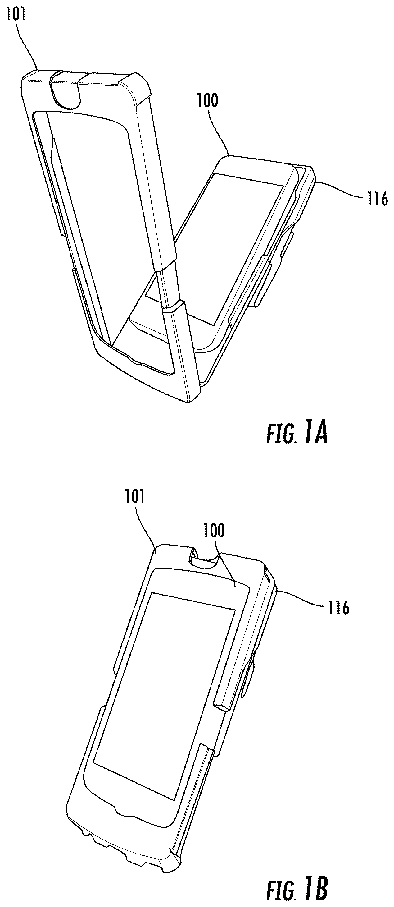
FIG. 1A depicts a mobile computing device 100 positioned in a portable peripheral 101 which is in open position.
FIG. 1B depicts the mobile computing device 100 and portable peripheral 101 in operation mode.
FIG. 1C schematically shows the circuitry of mobile computing device 100.
FIG. 1D schematically shows the circuitry of portable peripheral 101.
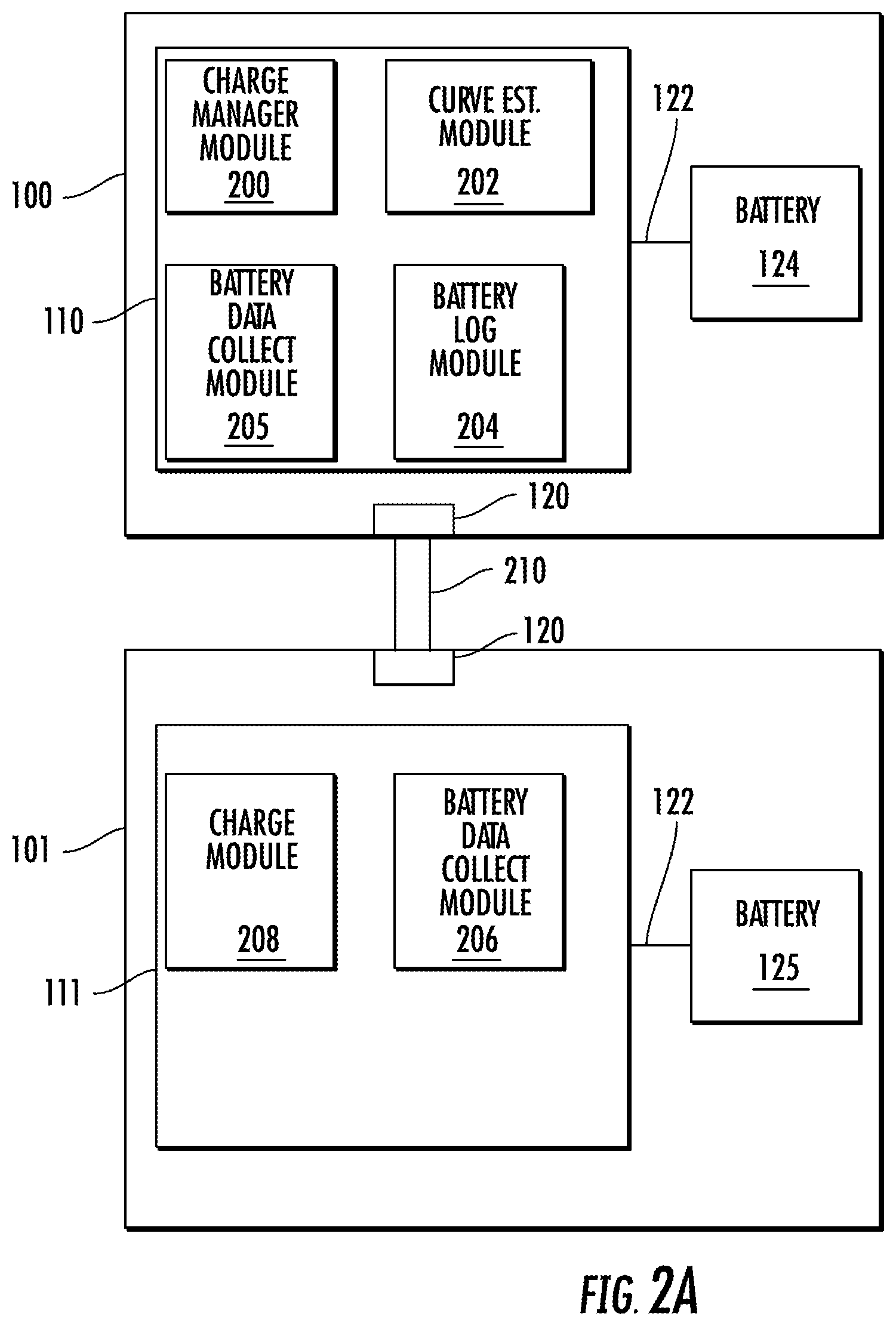
FIG. 2A schematically depicts an embodiment of the mobile computing device 100 and the portable peripheral 101 with a charge manager module 200, curve estimation module, and battery log module located on the mobile computing device 100.
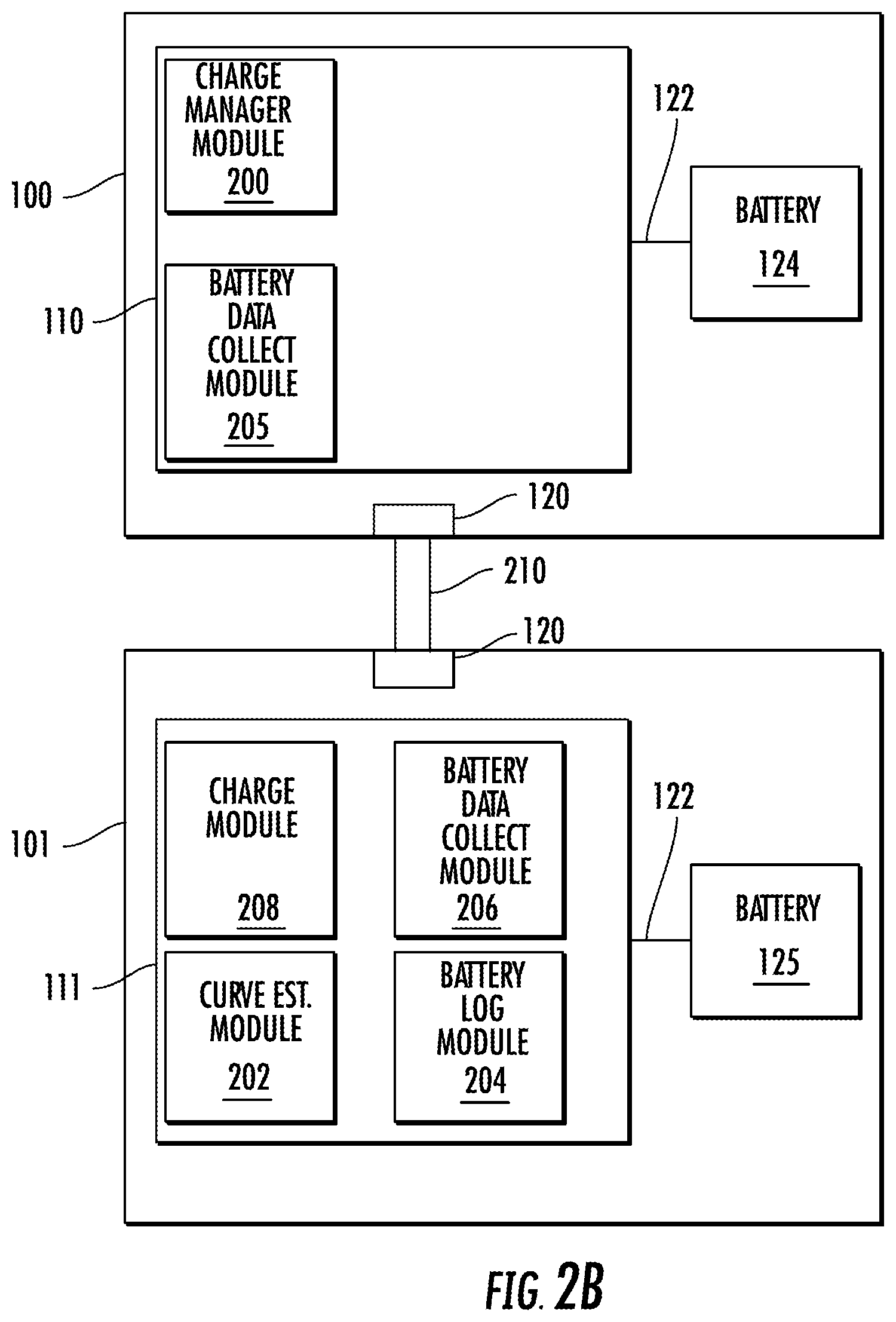
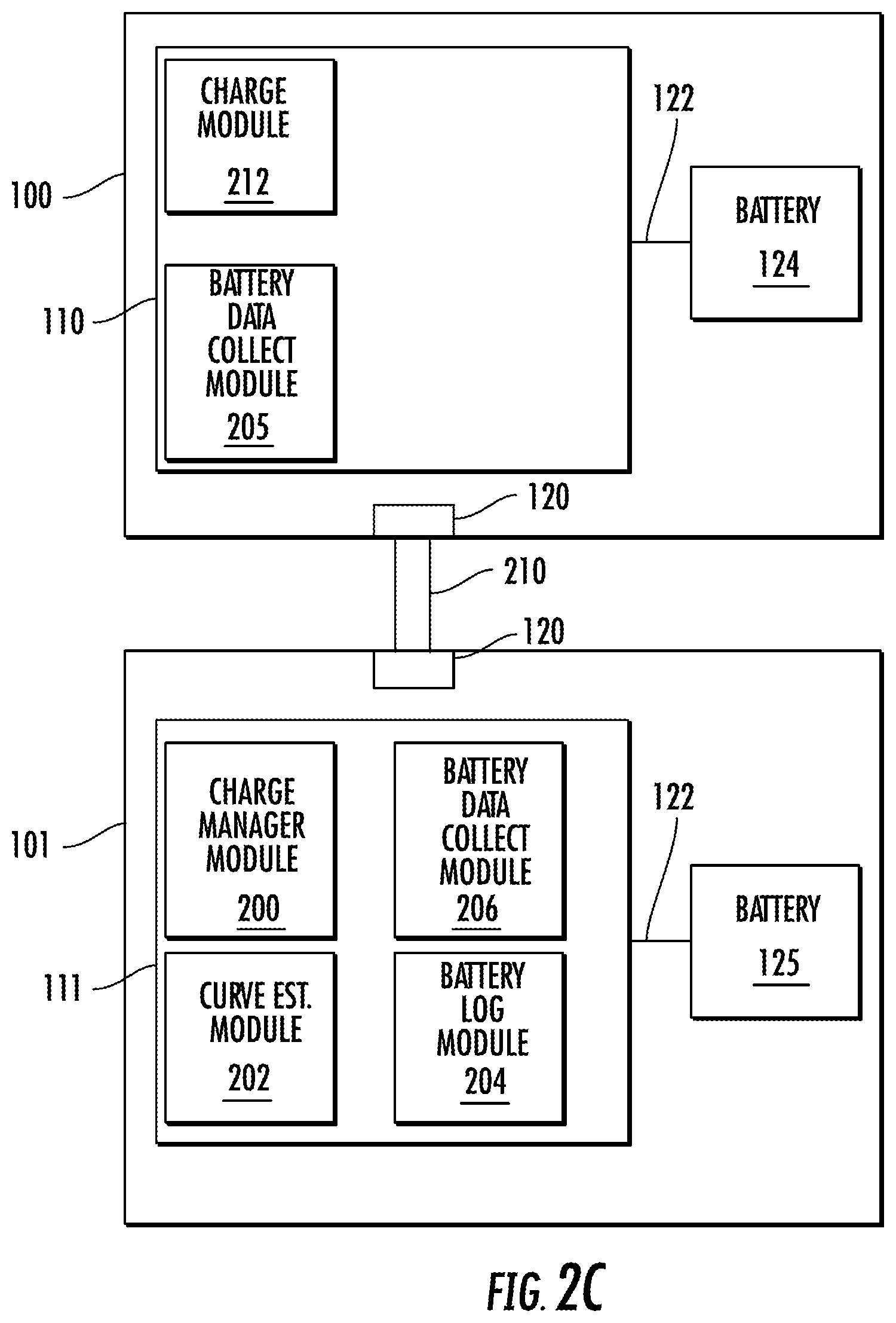
FIG. 2B schematically depicts another embodiment of the mobile computing device 100 and the portable peripheral 101 with the charge manager module located on the mobile computing device 100 and the curve estimation module and battery log module located on the peripheral device.
FIG. 2C schematically depicts another embodiment of the mobile computing device 100 and the portable peripheral 101 with the charge manager module, the curve estimation module and battery log module located on the peripheral device.
FIG. 3 illustrates a flowchart of the smart battery balance system and method of this disclosure.
DETAILED DESCRIPTION
In Honeywell.RTM. Sled scanning products, a Sled operates with a mobile smart computing device and can charge, for example, the smart computing device's battery with its own battery. However a mobile smart computing device such as an Apple.RTM. iPhone/iTouch devices cannot charge the Sled's battery because Apple.RTM. does not support (or allow) this. Therefore, oftentimes the Sled battery will be empty while an iPhone or iTouch will still have battery energy during usage. This results in energy wasted for a whole system.
The disclosure embraces a smart battery power balance management system and method (which may be called power balance management system or SmartCharge method herein) to maximize the operating life of a mobile computing device 100 and/or a portable peripheral 101. Portable peripheral 101 may be, for example, a peripheral having scanning or imaging capability. As shown in exemplary embodiments of FIGS. 1A and 1B, the mobile computing device 100 is capable of attaching to a chassis of portable peripheral 101 and working in conjunction with the portable peripheral 101. The mobile computing device 100 may be a handheld device and typically will slide into the portable peripheral 101 and may be snapped into place. Exemplary mobile computing devices 100 include a mobile phone, a wireless tablet device, a personal digital assistant (PDA), cellular phone, and smartphone (e.g., Apple.RTM. iPhone.RTM., iPod.RTM. Touch.RTM., iPad from Apple.RTM., Android.RTM. Smartphone). Portable peripheral 101 may have a docking input/output connection port (reference 120 in FIG. 1D) for electrical attachment (and maybe physical attachment) to the mobile computing device 100. The portable peripheral 101 may also be a handheld device which configured to envelope the mobile computing device 100. Typically, when the mobile computing device 100 is in the operating position it will be partially enclosed by the portable peripheral device 101 with primarily the screen of the mobile computing device visible. In the case of Apple.RTM. products the input/output connection could be a Lightning.TM. connector and for Android.RTM. devices a USB connection. The portable peripheral 101 transforms the mobile computing device 100 into an enterprise-ready device. The portable peripheral 101 may be a "code symbol" capturing scanner or imager which delivers fast and accurate reading of linear, two-dimensional and even poor quality bar codes. The term "code symbol" is intended broadly to refer to any machine-readable indicia that may be used to store information about an object (e.g., a barcode). An example of a portable peripheral 101 may be the Honeywell.RTM. Sled Captuvo SL22.
Upon connection of the mobile computing device 100 and the portable peripheral 101, power balance management software may be loaded from the portable peripheral 101 to the mobile computing device 100. In alternative embodiments, the power balance management software is loaded from the mobile computing device 100 to the portable peripheral 101. In other alternative embodiments it would be possible to download the power balance management software from a central site (e.g., the Apple.RTM. application store) into either or both devices 100 and 101.
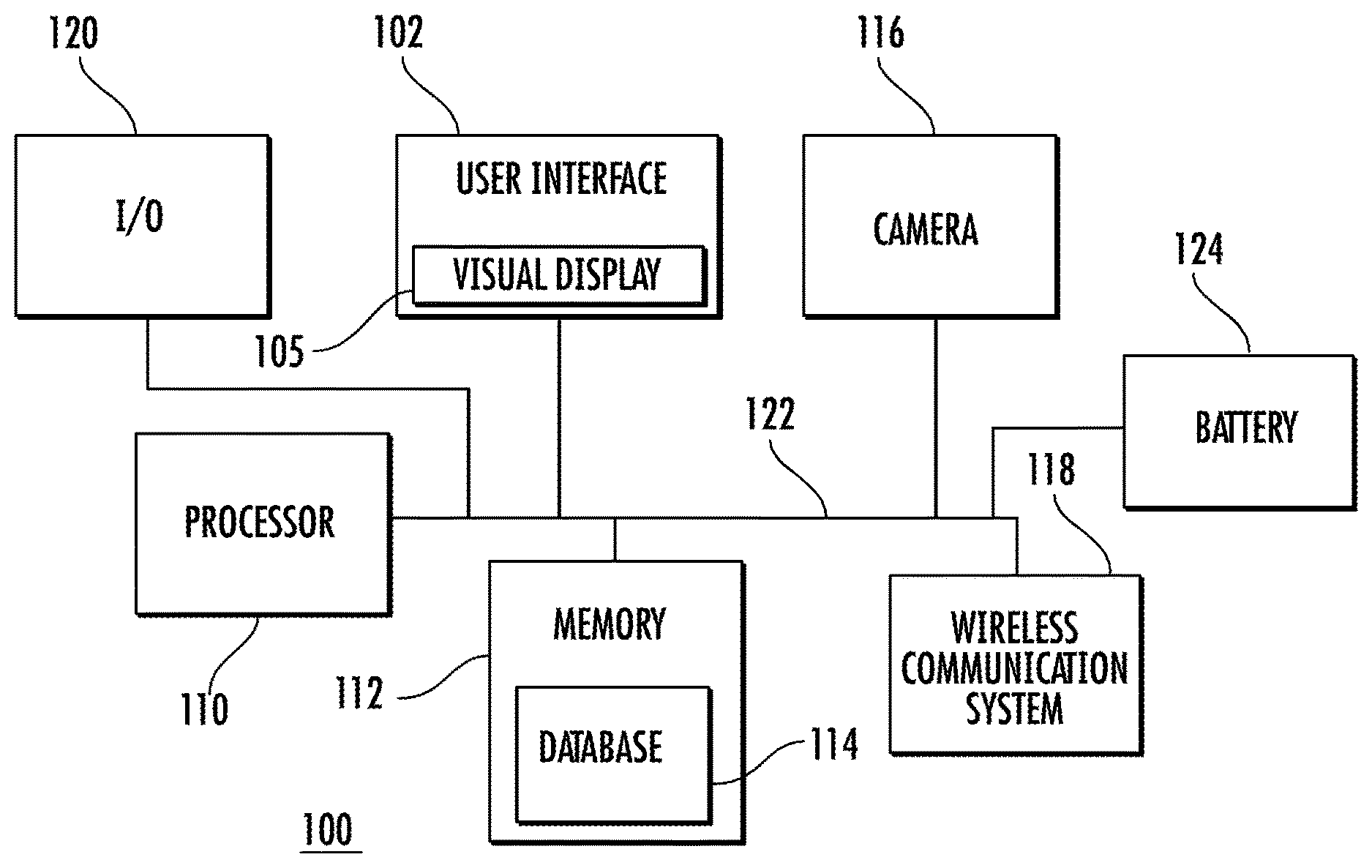
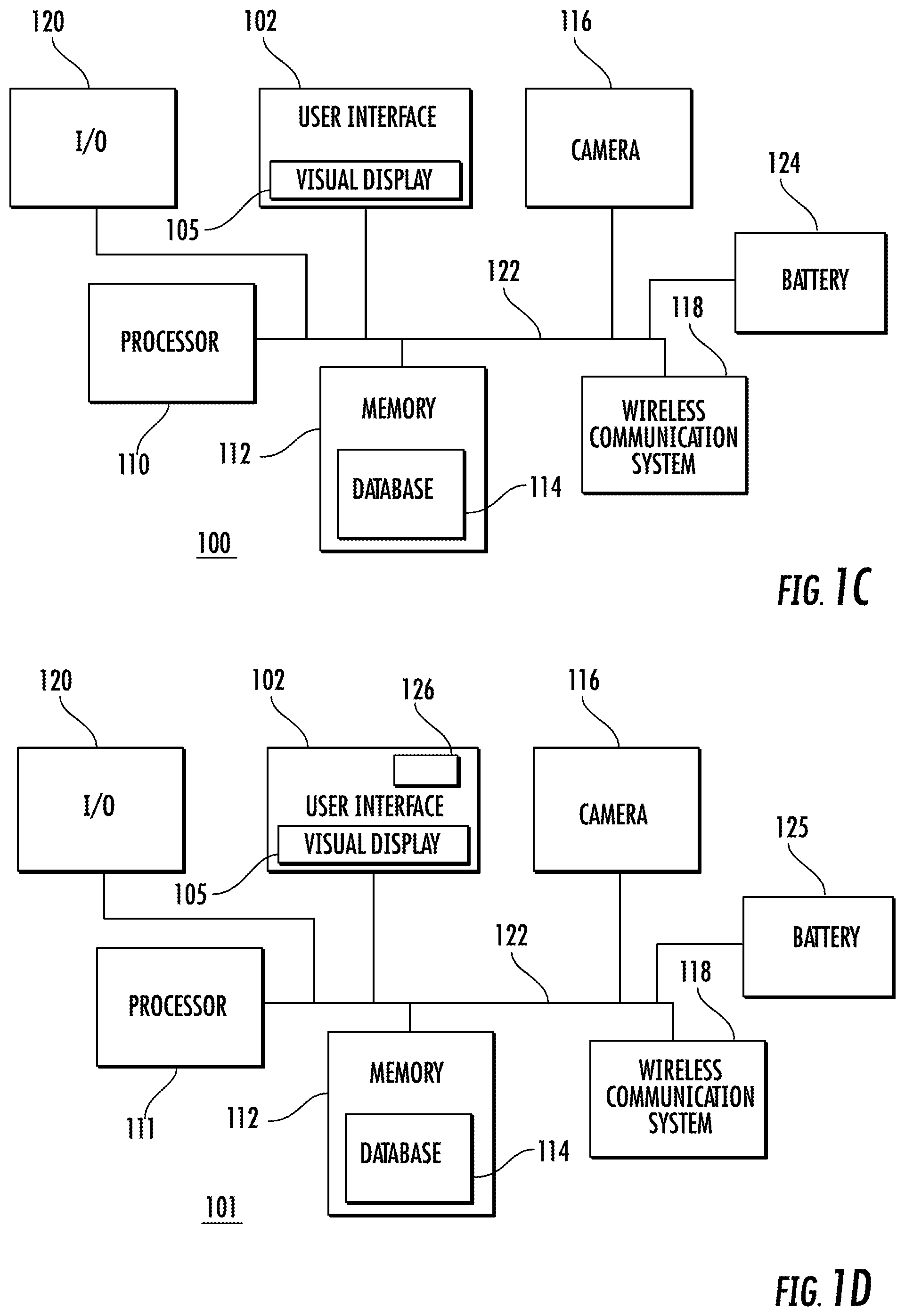
FIG. 1C illustrates that the mobile computing device 100 may broadly have a user interface system 102 including a touch screen 105 with a visual display and a soft keyboard. The mobile computing device 100 typically includes a processor (or processors) 110 having a set of stored programs ("applications"), which when executed by the processor 110, provides users with a variety of functionalities. The processor 110 is communicatively coupled with the user interface system 102, a memory 112 having a database 114, a camera 116, a wireless communication system 118, an input/output (I/O) module 120 and a battery 124. An exemplary mobile computing device 100 may include a system bus 122 and/or one or more interface circuits (not shown) for coupling the processor 110 and other components (e.g., user interface system 102, memory 112, camera 116, wireless communication system 118, I/O module 120 and battery 124) to the system bus 122 and to each other. Typically, the processor 110 is configured to execute instructions and to carry out operations associated with the mobile computing device 100. For example, using instructions retrieved from the memory 112 (e.g., a memory block), the processor 110 may control the reception and manipulation of input and output data between components of the mobile computing device 100. The processor 110 typically operates with an operating system to execute computer code and produce and use data. The operating system, other computer code, and data may reside within the memory 112 that is operatively coupled to the processor 110. The processor 110 may also download and execute any smart battery power balance management software described in detail below and also store that in memory 112. The memory 112 generally provides a place to store computer code and data that are used by the mobile computing device 100. The memory 112 may include Read-Only Memory (ROM), Random-Access Memory (RAM), a hard disk drive, and/or other non-transitory storage media. The operating system, other computer code, and data may also reside on a removable non-transitory storage medium that is loaded or installed onto the mobile computing device 100 when needed. The wireless communication system 118 enables the mobile computing device 100 to communicate with a wireless network, such as a cellular network (e.g., a GSM network, a CDMA network, or an LTE network), a local area network (LAN), and/or an ad hoc network. The I/O module 120 may be a hardwire connector which allows the mobile computing device 100 to receive power and/or data when plugged in. The I/O module 120 may also allow the mobile computing device 100 to connect to the portable peripheral 101 as discussed above. Also, connected to the I/O module 120 through bus 122 is the rechargeable battery 124 capable of providing power internally to the mobile computing device 100. The battery 124 can also provide power externally to and receive external power from the portable peripheral 101 when connected as will be discussed in detail herein. The processor 110 is also capable of monitoring the battery 124 to determine charging parameters such as percentage remaining charge, rate of charging, power consumption rate, time to empty and the like.
The portable peripheral 101 shown in FIG. 1D has many of the same elements functioning in the same way as the mobile computing device 100 as indicated by the same reference numerals. In the case of a scanner (or imager), the portable peripheral processor 111 may also be configured for capturing through camera 116 an image (e.g., a code symbol); displaying the image on the visual display 105; and determining whether the image is readable by the processor 111. The portable peripheral processor 111 may also enable various charging applications which are capable of monitoring portable peripheral rechargeable battery 125 to determine charging parameters such as percentage remaining charge, rate of charging, power consumption rate, time to empty and the like of battery 125. The portable peripheral 101 may also have an encryption-ready three-track magnetic stripe reader 126 in the user interface 102 which can be integrated, facilitating quick and easy processing of credit card transactions in the portable peripheral 101.
Compatibility with the mobile computing device 100 provides operators of the portable peripheral 101 access to a myriad of applications through the mobile computing device 100 from an online downloadable store. An example of mobile computing device 100 would be an Apple.RTM. iPhone which works with the Apple.RTM. Application Store to allow the operator of the iPhone to be armed with a tremendous amount of information. When equipped with software such as Honeywell's Remote MasterMind.TM. 3.0 software, operators of the portable peripheral 101 can remotely work with and/or manage a deployed mobile computing device 100 leading to a lower total cost of ownership. The protective housing of the portable peripheral 101 also adds durability to the mobile computing device 100 resulting in a combination that lowers the failure rate of the mobile computing device 100. As with the mobile computing device 100, in the portable peripheral 101 the I/O module 120 is connected through bus 122 to the rechargeable battery 125 and is capable of providing power to the portable peripheral 101 (and the mobile computing device battery 124) as discussed in detail herein.
FIG. 2A discloses a charge manager software module 200, curve filling estimation software module 202 ("curve estimation module"), a battery log 204, and a battery data collect module 205 running on the mobile computing device processor 110. A counterpart in the portable peripheral 101 to battery data collect module 205 is battery data collect module 206 which runs on the processor of the portable peripheral. Also running on the portable peripheral processor 111 is charge module 208 which takes direction from charge manager software module 200 and controls charging to and from the rechargeable battery 125. Elements 200, 202, 204, 205, 206, and 208 help make up the power balance management system and method described herein.
Element 210 in FIG. 2A stands for a connection interface between the I/O 120 of the mobile computing device 100 and I/O 120 of the portable peripheral 101. In the case where the mobile computing device 100 is an iPhone/iTouch the interface connection hardware may be a Lightning.TM. connector and may use iAP2 protocol software which is an Apple.RTM. accessory protocol to pass data back and forth. In the case where device 101 is an Android.RTM. phone a USB connector may be used with Android Open Accessory (AOA) protocol to pass data back and forth.
Charge manager software module 200 is the primary software with a user interface which may be displayed on the mobile computing device visual display 105 or on the portable peripheral visual display 105. One of the functions of the charge manager software module 200 is to check whether the operator has enabled the power balance management system functionality (i.e., Smartcharge) or not. If yes, software module 200 will start the battery power balance process. If not, it will not start the battery power balance method and will notify processors 110 and 111 to use a normal charge method. Curve filling estimation software module 202 performs a curve fitting and estimation to predict the empty time for complete battery discharge of the batteries 124, 125 of the mobile computing device 100 and portable peripheral 101 based on parameters obtained by monitoring the batteries 124, 125. Battery log 204 is configured to store history date of batteries 124 and 125. Mobile computing device battery data collect module 205 will be used to collect mobile computing device battery's 124 parameters (such as battery percentage of available power (Pp), power consumption, time to empty, and the like) through iOS.TM. or an Android.RTM. API and send them to the other modules 200, 202, and 204. Similarly, portable peripheral battery data collect module 206 shall be used to collect portable peripheral battery's 125 parameters (similar to battery 124, information such as battery percentage of available power (Ps), power consumption, time to empty, and the like) through the portable peripheral's API and forward them to modules 200, 202, and 204. Charge module 208 may be used to control the hardware of the portable peripheral 101 to enable or disable the charging of the mobile computing device battery 124 by the portable peripheral battery 125 during normal charging operations as well as permit charging of the portable peripheral battery 125 by the mobile computing device battery 124 during enablement of the power balance management system. Charge module 208 will receive instructions from charge manager module 200 on when to perform these functions.
The charge manager module 200 will obtain the parameters (e.g., Pp, Ps) from the collection modules 205 and 206. The charge manager module 200 can analyze these parameters to decide when to let the portable peripheral battery 125 charge the mobile portable computing device battery 124 and when to stop the portable peripheral 101 from charging the mobile computing device 100. The smart battery balance system and process can also use these parameters to decide when to let the mobile portable computing device battery 124 charge the portable peripheral battery 125 and when to stop the mobile computing device 100 from charging the portable peripheral 101. The charge manager module 200 may also use the battery parameters to determine the rate (or velocity) of battery consumption of mobile computing device 100 (Vp) and portable peripheral 101 (Vs). The battery empty time can then be predicted for the mobile computing device 100 (Tp) and the portable peripheral 101 (Ts). The charge manager module 200 may use a first method to obtain a prediction of the empty time (T) is to divide current battery percentage (P) with average battery consuming velocity (V.sub.mean) (i.e., T=P/V.sub.mean). Another method the charge manager module 200 may use to procure the predicted empty time of the batteries 124, 125 is to analyze historic battery percentage data and time to get a trend line for when the battery will be empty.
The charge manager module 200 will enable battery charging automatically and dynamically (i.e., constant change between charging and not charging) of the portable peripheral battery 125 (and also the mobile computing device battery 125). If the portable peripheral battery 125 empty time is longer than mobile computing device battery 124 empty time, then the smart battery balance process will let portable peripheral 101 charge the mobile computing device battery 124. If mobile computing device's battery 124 empty time is longer than portable peripheral's battery 125 empty time, then the smart battery power balance system and process will either stop portable peripheral 101 from charging the mobile computing device battery 124 or will actually have the mobile computing device 100 charge the rechargeable battery 125 of the portable peripheral. The idea is to maximize the battery life for the whole system so the mobile computing device battery 124 empty time is still maintained longer than the portable peripheral battery 125 empty time, but a more a balanced charge is maintained between the two devices. Because if nothing is done, the portable peripheral's battery 125 will be substantially 0% while the mobile computing device battery 124 is not and an operator cannot use the portable peripheral 101 to perform functions such as barcode scanning. With this battery power balancing system and process described herein enabled, it is possible to obtain the maximum uptime for both device 100 and peripheral 101.
FIG. 2B shows an alternative embodiment of the system of FIG. 2A. In this embodiment, the charge manager module 200 is located in the mobile computing device and running on processor 110. However, the curve estimation module 202 and battery log module 204 are running and performing their functions as described above on the portable peripheral 101 instead of the mobile device 100.
FIG. 2C shows another alternative embodiment of the systems of 2A and 2B. In this embodiment, the charge manager module 200, curve estimation module 202 and battery log module 204 are performing their functions but are all located in the portable peripheral. In this case, charge manager module will manage the charge of battery 125 and charge module 212 under instructions from module 200 will conduct charging operations of battery 124.
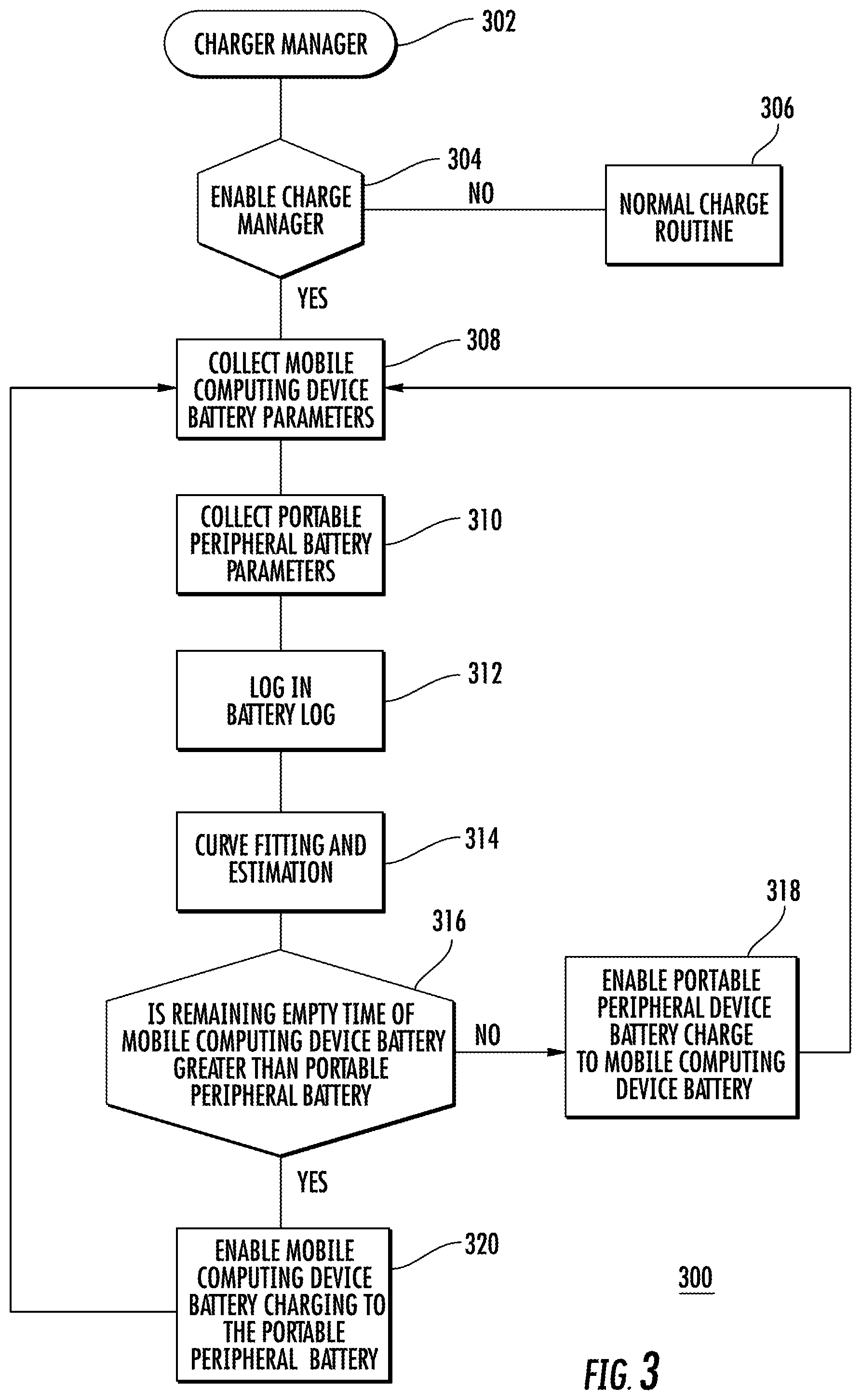
FIG. 3 shows a flowchart 300 of the process of the smart battery power balance management system. As described above, elements of the charging software (e.g., charge manager module 200, curve estimation module 202, battery log module 204, battery data collect modules 204, 206) may reside on both (or either of) the mobile computing device 100 and the portable peripheral 101 in the processors 110 and 111. Some portions are running on processor 110 and some are running on processor 111. The charge manager module software 200 is booted in step 302 in the mobile computing device 100 and the portable peripheral 101. In step 304, the battery power balance enablement decision is made. The battery power balance method can be enabled or disabled. If the operator chooses to enable, then the system will use the method described herein to maximize the whole battery life for both the mobile computing device 100 and portable peripheral 101 and proceed to step 308. If the operator chooses to disable the smart battery balance method (i.e., not use steps 308, 310, 312, 314, 316, 318, and 320), then in step 306 a normal charge routine is executed whereby the mobile computing device battery 124 is just charged when running low or becomes empty by the portable peripheral device battery 125. In this scenario, the portable peripheral 101 will keep charging the mobile computing device 100 no matter what the portable peripheral battery 125 percentage is or the portable peripheral 101 will charge the mobile computing device battery 124 at a predefined portable peripheral battery voltage range.
If enabled, in steps 308 and 310 the mobile computing device battery 124 and portable peripheral battery 125 parameters such as battery level, velocity/rate of consumption and usage history are collected by their respective processors (110 and 111) in modules 204, 206 and logged in step 312 in the battery log 204. In step 314, a curve fitting and estimation is done in curve estimation module 202 to predict the empty time for complete battery discharge of the device battery 124 and portable peripheral battery 125. As discussed above, equation T=P/V.sub.mean may be used to obtain the remaining battery hours. However, curve fitting and estimation may obtain a better estimate of a trend line using least squares method or linear regression to estimate the battery remaining time. In step 316, the portable peripheral remaining charge in the portable peripheral battery 125 is calculated. If the calculated empty time of the mobile computing device battery 124 is less than the portable peripheral battery 125 (i.e., "yes"), the process proceeds to step 318 and the portable peripheral charges the mobile computing device battery 124 and reverts to step 308. If in step 316, the calculated empty time of the mobile computing device battery 124 is greater than that of the portable peripheral battery 125 (i.e., "no"), the process proceeds to step 318. In this case, the portable peripheral battery 125 charging of the mobile computing device battery is disabled. In addition, the portable peripheral battery 125 may receive charging from the mobile computing device battery 124. The process then reverts back to step 308. The battery balancing steps are running regularly in a continuous loop of the steps in FIG. 3, so the battery charging from the mobile computing device 100 adjusts dynamically depending on the battery remaining hours calculation of the mobile computing device battery 124 and portable peripheral battery 125.
To supplement the present disclosure, this application incorporates entirely by reference the following commonly assigned patents, patent application publications, and patent applications: U.S. Pat. Nos. 6,832,725; 7,128,266; U.S. Pat. Nos. 7,159,783; 7,413,127; U.S. Pat. Nos. 7,726,575; 8,294,969; U.S. Pat. Nos. 8,317,105; 8,322,622; U.S. Pat. Nos. 8,366,005; 8,371,507; U.S. Pat. Nos. 8,376,233; 8,381,979; U.S. Pat. Nos. 8,390,909; 8,408,464; U.S. Pat. Nos. 8,408,468; 8,408,469; U.S. Pat. Nos. 8,424,768; 8,448,863; U.S. Pat. Nos. 8,457,013; 8,459,557; U.S. Pat. Nos. 8,469,272; 8,474,712; U.S. Pat. Nos. 8,479,992; 8,490,877; U.S. Pat. Nos. 8,517,271; 8,523,076; U.S. Pat. Nos. 8,528,818; 8,544,737; U.S. Pat. Nos. 8,548,242; 8,548,420; U.S. Pat. Nos. 8,550,335; 8,550,354; U.S. Pat. Nos. 8,550,357; 8,556,174; U.S. Pat. Nos. 8,556,176; 8,556,177; U.S. Pat. Nos. 8,559,767; 8,599,957; U.S. Pat. Nos. 8,561,895; 8,561,903; U.S. Pat. Nos. 8,561,905; 8,565,107; U.S. Pat. Nos. 8,571,307; 8,579,200; U.S. Pat. Nos. 8,583,924; 8,584,945; U.S. Pat. Nos. 8,587,595; 8,587,697; U.S. Pat. Nos. 8,588,869; 8,590,789; U.S. Pat. Nos. 8,596,539; 8,596,542; U.S. Pat. Nos. 8,596,543; 8,599,271; U.S. Pat. Nos. 8,599,957; 8,600,158; U.S. Pat. Nos. 8,600,167; 8,602,309; U.S. Pat. Nos. 8,608,053; 8,608,071; U.S. Pat. Nos. 8,611,309; 8,615,487; U.S. Pat. Nos. 8,616,454; 8,621,123; U.S. Pat. Nos. 8,622,303; 8,628,013; U.S. Pat. Nos. 8,628,015; 8,628,016; U.S. Pat. Nos. 8,629,926; 8,630,491; U.S. Pat. Nos. 8,635,309; 8,636,200; U.S. Pat. Nos. 8,636,212; 8,636,215; U.S. Pat. Nos. 8,636,224; 8,638,806; U.S. Pat. Nos. 8,640,958; 8,640,960; U.S. Pat. Nos. 8,643,717; 8,646,692; U.S. Pat. Nos. 8,646,694; 8,657,200; U.S. Pat. Nos. 8,659,397; 8,668,149; U.S. Pat. Nos. 8,678,285; 8,678,286; U.S. Pat. Nos. 8,682,077; 8,687,282; U.S. Pat. Nos. 8,692,927; 8,695,880; U.S. Pat. Nos. 8,698,949; 8,717,494; U.S. Pat. Nos. 8,717,494; 8,720,783; U.S. Pat. Nos. 8,723,804; 8,723,904; U.S. Pat. No. 8,727,223; U.S. Pat. No. D702,237; U.S. Pat. Nos. 8,740,082; 8,740,085; U.S. Pat. Nos. 8,746,563; 8,750,445; U.S. Pat. Nos. 8,752,766; 8,756,059; U.S. Pat. Nos. 8,757,495; 8,760,563; U.S. Pat. Nos. 8,763,909; 8,777,108; U.S. Pat. Nos. 8,777,109; 8,779,898; U.S. Pat. Nos. 8,781,520; 8,783,573; U.S. Pat. Nos. 8,789,757; 8,789,758; U.S. Pat. Nos. 8,789,759; 8,794,520; U.S. Pat. Nos. 8,794,522; 8,794,525; U.S. Pat. Nos. 8,794,526; 8,798,367; U.S. Pat. Nos. 8,807,431; 8,807,432; U.S. Pat. Nos. 8,820,630; 8,822,848; U.S. Pat. Nos. 8,824,692; 8,824,696; U.S. Pat. Nos. 8,842,849; 8,844,822; U.S. Pat. Nos. 8,844,823; 8,849,019; U.S. Pat. Nos. 8,851,383; 8,854,633; U.S. Pat. Nos. 8,866,963; 8,868,421; U.S. Pat. Nos. 8,868,519; 8,868,802; U.S. Pat. Nos. 8,868,803; 8,870,074; U.S. Pat. Nos. 8,879,639; 8,880,426; U.S. Pat. Nos. 8,881,983; 8,881,987; U.S. Pat. Nos. 8,903,172; 8,908,995; U.S. Pat. Nos. 8,910,870; 8,910,875; U.S. Pat. Nos. 8,914,290; 8,914,788; U.S. Pat. Nos. 8,915,439; 8,915,444; U.S. Pat. Nos. 8,916,789; 8,918,250; U.S. Pat. Nos. 8,918,564; 8,925,818; U.S. Pat. Nos. 8,939,374; 8,942,480; U.S. Pat. Nos. 8,944,313; 8,944,327; U.S. Pat. Nos. 8,944,332; 8,950,678; U.S. Pat. Nos. 8,967,468; 8,971,346; U.S. Pat. Nos. 8,976,030; 8,976,368; U.S. Pat. Nos. 8,978,981; 8,978,983; U.S. Pat. Nos. 8,978,984; 8,985,456; U.S. Pat. Nos. 8,985,457; 8,985,459; U.S. Pat. Nos. 8,985,461; 8,988,578; U.S. Pat. Nos. 8,988,590; 8,991,704; U.S. Pat. Nos. 8,996,194; 8,996,384; U.S. Pat. Nos. 9,002,641; 9,007,368; U.S. Pat. Nos. 9,010,641; 9,015,513; U.S. Pat. Nos. 9,016,576; 9,022,288; U.S. Pat. Nos. 9,030,964; 9,033,240; U.S. Pat. Nos. 9,033,242; 9,036,054; U.S. Pat. Nos. 9,037,344; 9,038,911; U.S. Pat. Nos. 9,038,915; 9,047,098; U.S. Pat. Nos. 9,047,359; 9,047,420; U.S. Pat. Nos. 9,047,525; 9,047,531; U.S. Pat. Nos. 9,053,055; 9,053,378; U.S. Pat. Nos. 9,053,380; 9,058,526; U.S. Pat. Nos. 9,064,165; 9,064,167; U.S. Pat. Nos. 9,064,168; 9,064,254; U.S. Pat. Nos. 9,066,032; 9,070,032; U.S. Design Pat. No. D716,285; U.S. Design Pat. No. D723,560; U.S. Design Pat. No. D730,357; U.S. Design Pat. No. D730,901; U.S. Design Pat. No. D730,902; U.S. Design Pat. No. D733,112; U.S. Design Pat. No. D734,339; International Publication No. 2013/163789; International Publication No. 2013/173985; International Publication No. 2014/019130; International Publication No. 2014/110495; U.S. Patent Application Publication No. 2008/0185432; U.S. Patent Application Publication No. 2009/0134221; U.S. Patent Application Publication No. 2010/0177080; U.S. Patent Application Publication No. 2010/0177076; U.S. Patent Application Publication No. 2010/0177707; U.S. Patent Application Publication No. 2010/0177749; U.S. Patent Application Publication No. 2010/0265880; U.S. Patent Application Publication No. 2011/0202554; U.S. Patent Application Publication No. 2012/0111946; U.S. Patent Application Publication No. 2012/0168511; U.S. Patent Application Publication No. 2012/0168512; U.S. Patent Application Publication No. 2012/0193423; U.S. Patent Application Publication No. 2012/0203647; U.S. Patent Application Publication No. 2012/0223141; U.S. Patent Application Publication No. 2012/0228382; U.S. Patent Application Publication No. 2012/0248188; U.S. Patent Application Publication No. 2013/0043312; U.S. Patent Application Publication No. 2013/0082104; U.S. Patent Application Publication No. 2013/0175341; U.S. Patent Application Publication No. 2013/0175343; U.S. Patent Application Publication No. 2013/0257744; U.S. Patent Application Publication No. 2013/0257759; U.S. Patent Application Publication No. 2013/0270346; U.S. Patent Application Publication No. 2013/0287258; U.S. Patent Application Publication No. 2013/0292475; U.S. Patent Application Publication No. 2013/0292477; U.S. Patent Application Publication No. 2013/0293539; U.S. Patent Application Publication No. 2013/0293540; U.S. Patent Application Publication No. 2013/0306728; U.S. Patent Application Publication No. 2013/0306731; U.S. Patent Application Publication No. 2013/0307964; U.S. Patent Application Publication No. 2013/0308625; U.S. Patent Application Publication No. 2013/0313324; U.S. Patent Application Publication No. 2013/0313325; U.S. Patent Application Publication No. 2013/0342717; U.S. Patent Application Publication No. 2014/0001267; U.S. Patent Application Publication No. 2014/0008439; U.S. Patent Application Publication No. 2014/0025584; U.S. Patent Application Publication No. 2014/0034734; U.S. Patent Application Publication No. 2014/0036848; U.S. Patent Application Publication No. 2014/0039693; U.S. Patent Application Publication No. 2014/0042814; U.S. Patent Application Publication No. 2014/0049120; U.S. Patent Application Publication No. 2014/0049635; U.S. Patent Application Publication No. 2014/0061306; U.S. Patent Application Publication No. 2014/0063289; U.S. Patent Application Publication No. 2014/0066136; U.S. Patent Application Publication No. 2014/0067692; U.S. Patent Application Publication No. 2014/0070005; U.S. Patent Application Publication No. 2014/0071840; U.S. Patent Application Publication No. 2014/0074746; U.S. Patent Application Publication No. 2014/0076974; U.S. Patent Application Publication No. 2014/0078341; U.S. Patent Application Publication No. 2014/0078345; U.S. Patent Application Publication No. 2014/0097249; U.S. Patent Application Publication No. 2014/0098792; U.S. Patent Application Publication No. 2014/0100813; U.S. Patent Application Publication No. 2014/0103115; U.S. Patent Application Publication No. 2014/0104413; U.S. Patent Application Publication No. 2014/0104414; U.S. Patent Application Publication No. 2014/0104416; U.S. Patent Application Publication No. 2014/0104451; U.S. Patent Application Publication No. 2014/0106594; U.S. Patent Application Publication No. 2014/0106725; U.S. Patent Application Publication No. 2014/0108010; U.S. Patent Application Publication No. 2014/0108402; U.S. Patent Application Publication No. 2014/0110485; U.S. Patent Application Publication No. 2014/0114530; U.S. Patent Application Publication No. 2014/0124577; U.S. Patent Application Publication No. 2014/0124579; U.S. Patent Application Publication No. 2014/0125842; U.S. Patent Application Publication No. 2014/0125853; U.S. Patent Application Publication No. 2014/0125999; U.S. Patent Application Publication No. 2014/0129378; U.S. Patent Application Publication No. 2014/0131438; U.S. Patent Application Publication No. 2014/0131441; U.S. Patent Application Publication No. 2014/0131443; U.S. Patent Application Publication No. 2014/0131444; U.S. Patent Application Publication No. 2014/0131445; U.S. Patent Application Publication No. 2014/0131448; U.S. Patent Application Publication No. 2014/0133379; U.S. Patent Application Publication No. 2014/0136208; U.S. Patent Application Publication No. 2014/0140585; U.S. Patent Application Publication No. 2014/0151453; U.S. Patent Application Publication No. 2014/0152882; U.S. Patent Application Publication No. 2014/0158770; U.S. Patent Application Publication No. 2014/0159869; U.S. Patent Application Publication No. 2014/0166755; U.S. Patent Application Publication No. 2014/0166759; U.S. Patent Application Publication No. 2014/0168787; U.S. Patent Application Publication No. 2014/0175165; U.S. Patent Application Publication No. 2014/0175172; U.S. Patent Application Publication No. 2014/0191644; U.S. Patent Application Publication No. 2014/0191913; U.S. Patent Application Publication No. 2014/0197238; U.S. Patent Application Publication No. 2014/0197239; U.S. Patent Application Publication No. 2014/0197304; U.S. Patent Application Publication No. 2014/0214631; U.S. Patent Application Publication No. 2014/0217166; U.S. Patent Application Publication No. 2014/0217180; U.S. Patent Application Publication No. 2014/0231500; U.S. Patent Application Publication No. 2014/0232930; U.S. Patent Application Publication No. 2014/0247315; U.S. Patent Application Publication No. 2014/0263493; U.S. Patent Application Publication No. 2014/0263645; U.S. Patent Application Publication No. 2014/0267609; U.S. Patent Application Publication No. 2014/0270196; U.S. Patent Application Publication No. 2014/0270229; U.S. Patent Application Publication No. 2014/0278387; U.S. Patent Application Publication No. 2014/0278391; U.S. Patent Application Publication No. 2014/0282210; U.S. Patent Application Publication No. 2014/0284384; U.S. Patent Application Publication No. 2014/0288933; U.S. Patent Application Publication No. 2014/0297058; U.S. Patent Application Publication No. 2014/0299665; U.S. Patent Application Publication No. 2014/0312121; U.S. Patent Application Publication No. 2014/0319220; U.S. Patent Application Publication No. 2014/0319221; U.S. Patent Application Publication No. 2014/0326787; U.S. Patent Application Publication No. 2014/0332590; U.S. Patent Application Publication No. 2014/0344943; U.S. Patent Application Publication No. 2014/0346233; U.S. Patent Application Publication No. 2014/0351317; U.S. Patent Application Publication No. 2014/0353373; U.S. Patent Application Publication No. 2014/0361073; U.S. Patent Application Publication No. 2014/0361082; U.S. Patent Application Publication No. 2014/0362184; U.S. Patent Application Publication No. 2014/0363015; U.S. Patent Application Publication No. 2014/0369511; U.S. Patent Application Publication No. 2014/0374483; U.S. Patent Application Publication No. 2014/0374485; U.S. Patent Application Publication No. 2015/0001301; U.S. Patent Application Publication No. 2015/0001304; U.S. Patent Application Publication No. 2015/0003673; U.S. Patent Application Publication No. 2015/0009338; U.S. Patent Application Publication No. 2015/0009610; U.S. Patent Application Publication No. 2015/0014416; U.S. Patent Application Publication No. 2015/0021397; U.S. Patent Application Publication No. 2015/0028102; U.S. Patent Application Publication No. 2015/0028103; U.S. Patent Application Publication No. 2015/0028104; U.S. Patent Application Publication No. 2015/0029002; U.S. Patent Application Publication No. 2015/0032709; U.S. Patent Application Publication No. 2015/0039309; U.S. Patent Application Publication No. 2015/0039878; U.S. Patent Application Publication No. 2015/0040378; U.S. Patent Application Publication No. 2015/0048168; U.S. Patent Application Publication No. 2015/0049347; U.S. Patent Application Publication No. 2015/0051992; U.S. Patent Application Publication No. 2015/0053766; U.S. Patent Application Publication No. 2015/0053768; U.S. Patent Application Publication No. 2015/0053769; U.S. Patent Application Publication No. 2015/0060544; U.S. Patent Application Publication No. 2015/0062366; U.S. Patent Application Publication No. 2015/0063215; U.S. Patent Application Publication No. 2015/0063676; U.S. Patent Application Publication No. 2015/0069130; U.S. Patent Application Publication No. 2015/0071819; U.S. Patent Application Publication No. 2015/0083800; U.S. Patent Application Publication No. 2015/0086114; U.S. Patent Application Publication No. 2015/0088522; U.S. Patent Application Publication No. 2015/0096872; U.S. Patent Application Publication No. 2015/0099557; U.S. Patent Application Publication No. 2015/0100196; U.S. Patent Application Publication No. 2015/0102109; U.S. Patent Application Publication No. 2015/0115035; U.S. Patent Application Publication No. 2015/0127791; U.S. Patent Application Publication No. 2015/0128116; U.S. Patent Application Publication No. 2015/0129659; U.S. Patent Application Publication No. 2015/0133047; U.S. Patent Application Publication No. 2015/0134470; U.S. Patent Application Publication No. 2015/0136851; U.S. Patent Application Publication No. 2015/0136854; U.S. Patent Application Publication No. 2015/0142492; U.S. Patent Application Publication No. 2015/0144692; U.S. Patent Application Publication No. 2015/0144698; U.S. Patent Application Publication No. 2015/0144701; U.S. Patent Application Publication No. 2015/0149946; U.S. Patent Application Publication No. 2015/0161429; U.S. Patent Application Publication No. 2015/0169925; U.S. Patent Application Publication No. 2015/0169929; U.S. Patent Application Publication No. 2015/0178523; U.S. Patent Application Publication No. 2015/0178534; U.S. Patent Application Publication No. 2015/0178535; U.S. Patent Application Publication No. 2015/0178536; U.S. Patent Application Publication No. 2015/0178537; U.S. Patent Application Publication No. 2015/0181093; U.S. Patent Application Publication No. 2015/0181109; U.S. patent application Ser. No. 13/367,978 for a Laser Scanning Module Employing an Elastomeric U-Hinge Based Laser Scanning Assembly, filed Feb. 7, 2012 (Feng et al.); U.S. patent application Ser. No. 29/458,405 for an Electronic Device, filed Jun. 19, 2013 (Fitch et al.); U.S. patent application Ser. No. 29/459,620 for an Electronic Device Enclosure, filed Jul. 2, 2013 (London et al.); U.S. patent application Ser. No. 29/468,118 for an Electronic Device Case, filed Sep. 26, 2013 (Oberpriller et al.); U.S. patent application Ser. No. 14/150,393 for Indicia-reader Having Unitary Construction Scanner, filed Jan. 8, 2014 (Colavito et al.); U.S. patent application Ser. No. 14/200,405 for Indicia Reader for Size-Limited Applications filed Mar. 7, 2014 (Feng et al.); U.S. patent application Ser. No. 14/231,898 for Hand-Mounted Indicia-Reading Device with Finger Motion Triggering filed Apr. 1, 2014 (Van Horn et al.); U.S. patent application Ser. No. 29/486,759 for an Imaging Terminal, filed Apr. 2, 2014 (Oberpriller et al.); U.S. patent application Ser. No. 14/257,364 for Docking System and Method Using Near Field Communication filed Apr. 21, 2014 (Showering); U.S. patent application Ser. No. 14/264,173 for Autofocus Lens System for Indicia Readers filed Apr. 29, 2014 (Ackley et al.); U.S. patent application Ser. No. 14/277,337 for MULTIPURPOSE OPTICAL READER, filed May 14, 2014 (Jovanovski et al.); U.S. patent application Ser. No. 14/283,282 for TERMINAL HAVING ILLUMINATION AND FOCUS CONTROL filed May 21, 2014 (Liu et al.); U.S. patent application Ser. No. 14/327,827 for a MOBILE-PHONE ADAPTER FOR ELECTRONIC TRANSACTIONS, filed Jul. 10, 2014 (Hejl); U.S. patent application Ser. No. 14/334,934 for a SYSTEM AND METHOD FOR INDICIA VERIFICATION, filed Jul. 18, 2014 (Hejl); U.S. patent application Ser. No. 14/339,708 for LASER SCANNING CODE SYMBOL READING SYSTEM, filed Jul. 24, 2014 (Xian et al.); U.S. patent application Ser. No. 14/340,627 for an AXIALLY REINFORCED FLEXIBLE SCAN ELEMENT, filed Jul. 25, 2014 (Rueblinger et al.); U.S. patent application Ser. No. 14/446,391 for MULTIFUNCTION POINT OF SALE APPARATUS WITH OPTICAL SIGNATURE CAPTURE filed Jul. 30, 2014 (Good et al.); U.S. patent application Ser. No. 14/452,697 for INTERACTIVE INDICIA READER, filed Aug. 6, 2014 (Todeschini); U.S. patent application Ser. No. 14/453,019 for DIMENSIONING SYSTEM WITH GUIDED ALIGNMENT, filed Aug. 6, 2014 (Li et al.); U.S. patent application Ser. No. 14/462,801 for MOBILE COMPUTING DEVICE WITH DATA COGNITION SOFTWARE, filed on Aug. 19, 2014 (Todeschini et al.); U.S. patent application Ser. No. 14/483,056 for VARIABLE DEPTH OF FIELD BARCODE SCANNER filed Sep. 10, 2014 (McCloskey et al.); U.S. patent application Ser. No. 14/513,808 for IDENTIFYING INVENTORY ITEMS IN A STORAGE FACILITY filed Oct. 14, 2014 (Singel et al.); U.S. patent application Ser. No. 14/519,195 for HANDHELD DIMENSIONING SYSTEM WITH FEEDBACK filed Oct. 21, 2014 (Laffargue et al.); U.S. patent application Ser. No. 14/519,179 for DIMENSIONING SYSTEM WITH MULTIPATH INTERFERENCE MITIGATION filed Oct. 21, 2014 (Thuries et al.); U.S. patent application Ser. No. 14/519,211 for SYSTEM AND METHOD FOR DIMENSIONING filed Oct. 21, 2014 (Ackley et al.); U.S. patent application Ser. No. 14/519,233 for HANDHELD DIMENSIONER WITH DATA-QUALITY INDICATION filed Oct. 21, 2014 (Laffargue et al.); U.S. patent application Ser. No. 14/519,249 for HANDHELD DIMENSIONING SYSTEM WITH MEASUREMENT-CONFORMANCE FEEDBACK filed Oct. 21, 2014 (Ackley et al.); U.S. patent application Ser. No.
14/527,191 for METHOD AND SYSTEM FOR RECOGNIZING SPEECH USING WILDCARDS IN AN EXPECTED RESPONSE filed Oct. 29, 2014 (Braho et al.); U.S. patent application Ser. No. 14/529,563 for ADAPTABLE INTERFACE FOR A MOBILE COMPUTING DEVICE filed Oct. 31, 2014 (Schoon et al.); U.S. patent application Ser. No. 14/529,857 for BARCODE READER WITH SECURITY FEATURES filed Oct. 31, 2014 (Todeschini et al.); U.S. patent application Ser. No. 14/398,542 for PORTABLE ELECTRONIC DEVICES HAVING A SEPARATE LOCATION TRIGGER UNIT FOR USE IN CONTROLLING AN APPLICATION UNIT filed Nov. 3, 2014 (Bian et al.); U.S. patent application Ser. No. 14/531,154 for DIRECTING AN INSPECTOR THROUGH AN INSPECTION filed Nov. 3, 2014 (Miller et al.); U.S. patent application Ser. No. 14/533,319 for BARCODE SCANNING SYSTEM USING WEARABLE DEVICE WITH EMBEDDED CAMERA filed Nov. 5, 2014 (Todeschini); U.S. patent application Ser. No. 14/535,764 for CONCATENATED EXPECTED RESPONSES FOR SPEECH RECOGNITION filed Nov. 7, 2014 (Braho et al.); U.S. patent application Ser. No. 14/568,305 for AUTO-CONTRAST VIEWFINDER FOR AN INDICIA READER filed Dec. 12, 2014 (Todeschini); U.S. patent application Ser. No. 14/573,022 for DYNAMIC DIAGNOSTIC INDICATOR GENERATION filed Dec. 17, 2014 (Goldsmith); U.S. patent application Ser. No. 14/578,627 for SAFETY SYSTEM AND METHOD filed Dec. 22, 2014 (Ackley et al.); U.S. patent application Ser. No. 14/580,262 for MEDIA GATE FOR THERMAL TRANSFER PRINTERS filed Dec. 23, 2014 (Bowles); U.S. patent application Ser. No. 14/590,024 for SHELVING AND PACKAGE LOCATING SYSTEMS FOR DELIVERY VEHICLES filed Jan. 6, 2015 (Payne); U.S. patent application Ser. No. 14/596,757 for SYSTEM AND METHOD FOR DETECTING BARCODE PRINTING ERRORS filed Jan. 14, 2015 (Ackley); U.S. patent application Ser. No. 14/416,147 for OPTICAL READING APPARATUS HAVING VARIABLE SETTINGS filed Jan. 21, 2015 (Chen et al.); U.S. patent application Ser. No. 14/614,706 for DEVICE FOR SUPPORTING AN ELECTRONIC TOOL ON A USER'S HAND filed Feb. 5, 2015 (Oberpriller et al.); U.S. patent application Ser. No. 14/614,796 for CARGO APPORTIONMENT TECHNIQUES filed Feb. 5, 2015 (Morton et al.); U.S. patent application Ser. No. 29/516,892 for TABLE COMPUTER filed Feb. 6, 2015 (Bidwell et al.); U.S. patent application Ser. No. 14/619,093 for METHODS FOR TRAINING A SPEECH RECOGNITION SYSTEM filed Feb. 11, 2015 (Pecorari); U.S. patent application Ser. No. 14/628,708 for DEVICE, SYSTEM, AND METHOD FOR DETERMINING THE STATUS OF CHECKOUT LANES filed Feb. 23, 2015 (Todeschini); U.S. patent application Ser. No. 14/630,841 for TERMINAL INCLUDING IMAGING ASSEMBLY filed Feb. 25, 2015 (Gomez et al.); U.S. patent application Ser. No. 14/635,346 for SYSTEM AND METHOD FOR RELIABLE STORE-AND-FORWARD DATA HANDLING BY ENCODED INFORMATION READING TERMINALS filed Mar. 2, 2015 (Sevier); U.S. patent application Ser. No. 29/519,017 for SCANNER filed Mar. 2, 2015 (Zhou et al.); U.S. patent application Ser. No. 14/405,278 for DESIGN PATTERN FOR SECURE STORE filed Mar. 9, 2015 (Zhu et al.); U.S. patent application Ser. No. 14/660,970 for DECODABLE INDICIA READING TERMINAL WITH COMBINED ILLUMINATION filed Mar. 18, 2015 (Kearney et al.); U.S. patent application Ser. No. 14/661,013 for REPROGRAMMING SYSTEM AND METHOD FOR DEVICES INCLUDING PROGRAMMING SYMBOL filed Mar. 18, 2015 (Soule et al.); U.S. patent application Ser. No. 14/662,922 for MULTIFUNCTION POINT OF SALE SYSTEM filed Mar. 19, 2015 (Van Horn et al.); U.S. patent application Ser. No. 14/663,638 for VEHICLE MOUNT COMPUTER WITH CONFIGURABLE IGNITION SWITCH BEHAVIOR filed Mar. 20, 2015 (Davis et al.); U.S. patent application Ser. No. 14/664,063 for METHOD AND APPLICATION FOR SCANNING A BARCODE WITH A SMART DEVICE WHILE CONTINUOUSLY RUNNING AND DISPLAYING AN APPLICATION ON THE SMART DEVICE DISPLAY filed Mar. 20, 2015 (Todeschini); U.S. patent application Ser. No. 14/669,280 for TRANSFORMING COMPONENTS OF A WEB PAGE TO VOICE PROMPTS filed Mar. 26, 2015 (Funyak et al.); U.S. patent application Ser. No. 14/674,329 for AIMER FOR BARCODE SCANNING filed Mar. 31, 2015 (Bidwell); U.S. patent application Ser. No. 14/676,109 for INDICIA READER filed Apr. 1, 2015 (Huck); U.S. patent application Ser. No. 14/676,327 for DEVICE MANAGEMENT PROXY FOR SECURE DEVICES filed Apr. 1, 2015 (Yeakley et al.); U.S. patent application Ser. No. 14/676,898 for NAVIGATION SYSTEM CONFIGURED TO INTEGRATE MOTION SENSING DEVICE INPUTS filed Apr. 2, 2015 (Showering); U.S. patent application Ser. No. 14/679,275 for DIMENSIONING SYSTEM CALIBRATION SYSTEMS AND METHODS filed Apr. 6, 2015 (Laffargue et al.); U.S. patent application Ser. No. 29/523,098 for HANDLE FOR A TABLET COMPUTER filed Apr. 7, 2015 (Bidwell et al.); U.S. patent application Ser. No. 14/682,615 for SYSTEM AND METHOD FOR POWER MANAGEMENT OF MOBILE DEVICES filed Apr. 9, 2015 (Murawski et al.); U.S. patent application Ser. No. 14/686,822 for MULTIPLE PLATFORM SUPPORT SYSTEM AND METHOD filed Apr. 15, 2015 (Qu et al.); U.S. patent application Ser. No. 14/687,289 for SYSTEM FOR COMMUNICATION VIA A PERIPHERAL HUB filed Apr. 15, 2015 (Kohtz et al.); U.S. patent application Ser. No. 29/524,186 for SCANNER filed Apr. 17, 2015 (Zhou et al.); U.S. patent application Ser. No. 14/695,364 for MEDICATION MANAGEMENT SYSTEM filed Apr. 24, 2015 (Sewell et al.); U.S. patent application Ser. No. 14/695,923 for SECURE UNATTENDED NETWORK AUTHENTICATION filed Apr. 24, 2015 (Kubler et al.); U.S. patent application Ser. No. 29/525,068 for TABLET COMPUTER WITH REMOVABLE SCANNING DEVICE filed Apr. 27, 2015 (Schulte et al.); U.S. patent application Ser. No. 14/699,436 for SYMBOL READING SYSTEM HAVING PREDICTIVE DIAGNOSTICS filed Apr. 29, 2015 (Nahill et al.); U.S. patent application Ser. No. 14/702,110 for SYSTEM AND METHOD FOR REGULATING BARCODE DATA INJECTION INTO A RUNNING APPLICATION ON A SMART DEVICE filed May 1, 2015 (Todeschini et al.); U.S. patent application Ser. No. 14/702,979 for TRACKING BATTERY CONDITIONS filed May 4, 2015 (Young et al.); U.S. patent application Ser. No. 14/704,050 for INTERMEDIATE LINEAR POSITIONING filed May 5, 2015 (Charpentier et al.); U.S. patent application Ser. No. 14/705,012 for HANDS-FREE HUMAN MACHINE INTERFACE RESPONSIVE TO A DRIVER OF A VEHICLE filed May 6, 2015 (Fitch et al.); U.S. patent application Ser. No. 14/705,407 for METHOD AND SYSTEM TO PROTECT SOFTWARE-BASED NETWORK-CONNECTED DEVICES FROM ADVANCED PERSISTENT THREAT filed May 6, 2015 (Hussey et al.); U.S. patent application Ser. No. 14/707,037 for SYSTEM AND METHOD FOR DISPLAY OF INFORMATION USING A VEHICLE-MOUNT COMPUTER filed May 8, 2015 (Chamberlin); U.S. patent application Ser. No. 14/707,123 for APPLICATION INDEPENDENT DEX/UCS INTERFACE filed May 8, 2015 (Pape); U.S. patent application Ser. No. 14/707,492 for METHOD AND APPARATUS FOR READING OPTICAL INDICIA USING A PLURALITY OF DATA SOURCES filed May 8, 2015 (Smith et al.); U.S. patent application Ser. No. 14/710,666 for PRE-PAID USAGE SYSTEM FOR ENCODED INFORMATION READING TERMINALS filed May 13, 2015 (Smith); U.S. patent application Ser. No. 29/526,918 for CHARGING BASE filed May 14, 2015 (Fitch et al.); U.S. patent application Ser. No. 14/715,672 for AUGUMENTED REALITY ENABLED HAZARD DISPLAY filed May 19, 2015 (Venkatesha et al.); U.S. patent application Ser. No. 14/715,916 for EVALUATING IMAGE VALUES filed May 19, 2015 (Ackley); U.S. patent application Ser. No. 14/722,608 for INTERACTIVE USER INTERFACE FOR CAPTURING A DOCUMENT IN AN IMAGE SIGNAL filed May 27, 2015 (Showering et al.); U.S. patent application Ser. No. 29/528,165 for IN-COUNTER BARCODE SCANNER filed May 27, 2015 (Oberpriller et al.); U.S. patent application Ser. No. 14/724,134 for ELECTRONIC DEVICE WITH WIRELESS PATH SELECTION CAPABILITY filed May 28, 2015 (Wang et al.); U.S. patent application Ser. No. 14/724,849 for METHOD OF PROGRAMMING THE DEFAULT CABLE INTERFACE SOFTWARE IN AN INDICIA READING DEVICE filed May 29, 2015 (Barten); U.S. patent application Ser. No. 14/724,908 for IMAGING APPARATUS HAVING IMAGING ASSEMBLY filed May 29, 2015 (Barber et al.); U.S. patent application Ser. No. 14/725,352 for APPARATUS AND METHODS FOR MONITORING ONE OR MORE PORTABLE DATA TERMINALS (Caballero et al.); U.S. patent application Ser. No. 29/528,590 for ELECTRONIC DEVICE filed May 29, 2015 (Fitch et al.); U.S. patent application Ser. No. 29/528,890 for MOBILE COMPUTER HOUSING filed Jun. 2, 2015 (Fitch et al.); U.S. patent application Ser. No. 14/728,397 for DEVICE MANAGEMENT USING VIRTUAL INTERFACES CROSS-REFERENCE TO RELATED APPLICATIONS filed Jun. 2, 2015 (Caballero); U.S. patent application Ser. No. 14/732,870 for DATA COLLECTION MODULE AND SYSTEM filed Jun. 8, 2015 (Powilleit); U.S. patent application Ser. No. 29/529,441 for INDICIA READING DEVICE filed Jun. 8, 2015 (Zhou et al.); U.S. patent application Ser. No. 14/735,717 for INDICIA-READING SYSTEMS HAVING AN INTERFACE WITH A USER'S NERVOUS SYSTEM filed Jun. 10, 2015 (Todeschini); U.S. patent application Ser. No. 14/738,038 for METHOD OF AND SYSTEM FOR DETECTING OBJECT WEIGHING INTERFERENCES filed Jun. 12, 2015 (Amundsen et al.); U.S. patent application Ser. No. 14/740,320 for TACTILE SWITCH FOR A MOBILE ELECTRONIC DEVICE filed Jun. 16, 2015 (Bandringa); U.S. patent application Ser. No. 14/740,373 for CALIBRATING A VOLUME DIMENSIONER filed Jun. 16, 2015 (Ackley et al.); U.S. patent application Ser. No. 14/742,818 for INDICIA READING SYSTEM EMPLOYING DIGITAL GAIN CONTROL filed Jun. 18, 2015 (Xian et al.); U.S. patent application Ser. No. 14/743,257 for WIRELESS MESH POINT PORTABLE DATA TERMINAL filed Jun. 18, 2015 (Wang et al.); U.S. patent application Ser. No. 29/530,600 for CYCLONE filed Jun. 18, 2015 (Vargo et al); U.S. patent application Ser. No. 14/744,633 for IMAGING APPARATUS COMPRISING IMAGE SENSOR ARRAY HAVING SHARED GLOBAL SHUTTER CIRCUITRY filed Jun. 19, 2015 (Wang); U.S. patent application Ser. No. 14/744,836 for CLOUD-BASED SYSTEM FOR READING OF DECODABLE INDICIA filed Jun. 19, 2015 (Todeschini et al.); U.S. patent application Ser. No. 14/745,006 for SELECTIVE OUTPUT OF DECODED MESSAGE DATA filed Jun. 19, 2015 (Todeschini et al.); U.S. patent application Ser. No. 14/747,197 for OPTICAL PATTERN PROJECTOR filed Jun. 23, 2015 (Thuries et al.); U.S. patent application Ser. No. 14/747,490 for DUAL-PROJECTOR THREE-DIMENSIONAL SCANNER filed Jun. 23, 2015 (Jovanovski et al.); and U.S. patent application Ser. No. 14/748,446 for CORDLESS INDICIA READER WITH A MULTIFUNCTION COIL FOR WIRELESS CHARGING AND EAS DEACTIVATION, filed Jun. 24, 2015 (Xie et al.).
In the specification and/or figures, typical embodiments of the invention have been disclosed. The present invention is not limited to such exemplary embodiments. The use of the term "and/or" includes any and all combinations of one or more of the associated listed items. The figures are schematic representations and so are not necessarily drawn to scale. Unless otherwise noted, specific terms have been used in a generic and descriptive sense and not for purposes of limitation.
Devices that are described as in "communication" with each other or "coupled" to each other need not be in continuous communication with each other or in direct physical contact, unless expressly specified otherwise. On the contrary, such devices need only transmit to each other as necessary or desirable, and may actually refrain from exchanging data most of the time. For example, a machine in communication with or coupled with another machine via the Internet may not transmit data to the other machine for long period of time (e.g. weeks at a time). In addition, devices that are in communication with or coupled with each other may communicate directly or indirectly through one or more intermediaries.
Although process (or method) steps may be described or claimed in a particular sequential order, such processes may be configured to work in different orders. In other words, any sequence or order of steps that may be explicitly described or claimed does not necessarily indicate a requirement that the steps be performed in that order unless specifically indicated. Further, some steps may be performed simultaneously despite being described or implied as occurring non-simultaneously (e.g., because one step is described after the other step) unless specifically indicated. Where a process is described in an embodiment the process may operate without any user intervention.
* * * * *
D00000
D00001
D00002
D00003
D00004
D00005
D00006
XML
uspto.report is an independent third-party trademark research tool that is not affiliated, endorsed, or sponsored by the United States Patent and Trademark Office (USPTO) or any other governmental organization. The information provided by uspto.report is based on publicly available data at the time of writing and is intended for informational purposes only.
While we strive to provide accurate and up-to-date information, we do not guarantee the accuracy, completeness, reliability, or suitability of the information displayed on this site. The use of this site is at your own risk. Any reliance you place on such information is therefore strictly at your own risk.
All official trademark data, including owner information, should be verified by visiting the official USPTO website at www.uspto.gov. This site is not intended to replace professional legal advice and should not be used as a substitute for consulting with a legal professional who is knowledgeable about trademark law.