Cold weather vented garment
Pezzimenti , et al.
U.S. patent number 10,694,797 [Application Number 15/255,601] was granted by the patent office on 2020-06-30 for cold weather vented garment. This patent grant is currently assigned to NIKE, Inc.. The grantee listed for this patent is NIKE, Inc.. Invention is credited to Irena Ilcheva, Lindsey V. J. Martin, Luke A. Pezzimenti.


| United States Patent | 10,694,797 |
| Pezzimenti , et al. | June 30, 2020 |
Cold weather vented garment
Abstract
The present invention relates to breathable, vented, and insulating cold weather garments. More particularly, the present invention relates to garments with chambers to retain an insulating fill material. Perforations along the seams between the insulating chambers may achieve optimal evaporative moisture transfer from the inside (proximal to the body of a wearer) of the garment to the outside environment.
| Inventors: | Pezzimenti; Luke A. (Portland, OR), Martin; Lindsey V. J. (Portland, OR), Ilcheva; Irena (Beaverton, OR) | ||||||||||
|---|---|---|---|---|---|---|---|---|---|---|---|
| Applicant: |
|
||||||||||
| Assignee: | NIKE, Inc. (Beaverton,
OR) |
||||||||||
| Family ID: | 49378736 | ||||||||||
| Appl. No.: | 15/255,601 | ||||||||||
| Filed: | September 2, 2016 |
Prior Publication Data
| Document Identifier | Publication Date | |
|---|---|---|
| US 20160366962 A1 | Dec 22, 2016 | |
Related U.S. Patent Documents
| Application Number | Filing Date | Patent Number | Issue Date | ||
|---|---|---|---|---|---|
| 15140214 | Apr 27, 2016 | 10362820 | |||
| 13449783 | Jul 19, 2016 | 9392825 | |||
| Current U.S. Class: | 1/1 |
| Current CPC Class: | A41D 27/28 (20130101); A41D 27/24 (20130101); A41D 31/102 (20190201); A41D 27/245 (20130101); A41D 31/065 (20190201); A41D 3/02 (20130101); A41D 31/14 (20190201); B29C 65/02 (20130101); A41D 13/002 (20130101); B29C 66/0326 (20130101); B29C 66/433 (20130101); B29C 66/436 (20130101); B29C 65/5057 (20130101); B29C 66/729 (20130101); B29C 66/1122 (20130101); B29C 65/62 (20130101); B29C 66/8322 (20130101); B29C 65/08 (20130101); B29L 2031/485 (20130101); B29C 2793/0045 (20130101); A41D 2400/10 (20130101); B29C 66/0346 (20130101); B29C 65/7437 (20130101) |
| Current International Class: | A41D 27/28 (20060101); A41D 31/102 (20190101); A41D 31/14 (20190101); A41D 31/06 (20190101); A41D 27/24 (20060101) |
| Field of Search: | ;2/69 |
References Cited [Referenced By]
U.S. Patent Documents
| 317711 | May 1885 | Beinkmanf |
| 385306 | June 1888 | Helwitz |
| 1252187 | January 1918 | Shane |
| 1252188 | January 1918 | Shane |
| 1612010 | December 1926 | Gray |
| 1788731 | January 1931 | Mishel |
| 2084173 | June 1937 | Wexler |
| 2121836 | June 1938 | Steinberger et al. |
| 2353984 | July 1944 | Barone |
| 2372632 | March 1945 | Webb et al. |
| 2385124 | September 1945 | Barone |
| 2464380 | March 1949 | Daiber |
| 2466911 | April 1949 | Raymond |
| 2851390 | September 1958 | Chavannes |
| 3115564 | December 1963 | Stacy |
| 3405674 | October 1968 | Coates et al. |
| 3562041 | February 1971 | Robertson |
| 3706102 | December 1972 | Grenier |
| 3761962 | October 1973 | Myers |
| 3771170 | November 1973 | Leon |
| 3819465 | June 1974 | Parsons et al. |
| 3852144 | December 1974 | Parry |
| 3876493 | April 1975 | Gilmore |
| 4039709 | August 1977 | Newman |
| 4048675 | September 1977 | Griffin |
| 4115610 | September 1978 | Wortman |
| 4181993 | January 1980 | McDaniel |
| 4185327 | January 1980 | Markve |
| 4251312 | February 1981 | Ziegler, Jr. et al. |
| 4311542 | January 1982 | Mueller et al. |
| 4370754 | February 1983 | Donzis |
| 4396039 | August 1983 | Klenk |
| 4471759 | September 1984 | Anderson et al. |
| 4496407 | January 1985 | Lowery, Sr. et al. |
| 4502153 | March 1985 | Lapedes et al. |
| 4560427 | December 1985 | Flood |
| 4604152 | August 1986 | Liukko |
| 4608715 | September 1986 | Miller et al. |
| 4610750 | September 1986 | Mango |
| 4625336 | December 1986 | Derderian |
| 4693771 | September 1987 | Payet et al. |
| 4713131 | December 1987 | Obeda |
| 4716598 | January 1988 | Bertram |
| 4737212 | April 1988 | Emrich et al. |
| 4756937 | July 1988 | Mentzer |
| 4788972 | December 1988 | Debusk |
| 4791685 | December 1988 | Maibauer |
| 4938817 | July 1990 | Langley |
| 4962554 | October 1990 | Tesch |
| 4971041 | November 1990 | Millikan et al. |
| 5001783 | March 1991 | Grilliot et al. |
| 5003902 | April 1991 | Benstock et al. |
| 5021280 | June 1991 | Farnworth et al. |
| 5048126 | September 1991 | McLaughlin |
| 5067178 | November 1991 | Katchka et al. |
| 5131097 | July 1992 | Grilliot et al. |
| 5165115 | November 1992 | Stanislaw et al. |
| 5168576 | December 1992 | Krent et al. |
| 5255392 | October 1993 | Stanislaw et al. |
| 5267519 | December 1993 | Uglene et al. |
| 5408700 | April 1995 | Reuben et al. |
| 5445863 | August 1995 | Slagle et al. |
| 5446927 | September 1995 | Weldon |
| 5483713 | January 1996 | Kikuchi et al. |
| 5526534 | June 1996 | Lazar |
| 5665196 | September 1997 | Combe et al. |
| 5692245 | December 1997 | Reuben |
| 5713079 | February 1998 | Simon et al. |
| 5787502 | August 1998 | Middleton |
| 5799600 | September 1998 | Reuben |
| 5885679 | March 1999 | Yasue et al. |
| 5924134 | July 1999 | Taylor et al. |
| 5935878 | August 1999 | Glasser |
| 6009560 | January 2000 | McKenney et al. |
| 6018819 | February 2000 | King et al. |
| 6038700 | March 2000 | Aldridge et al. |
| 6049908 | April 2000 | Bullock et al. |
| 6076196 | June 2000 | Masumoto |
| 6112328 | September 2000 | Spector |
| 6182297 | February 2001 | Duren et al. |
| 6279161 | August 2001 | Johnston |
| 6332221 | December 2001 | Gracey |
| 6339843 | January 2002 | Grilliot et al. |
| 6405375 | June 2002 | Sardi |
| 6547327 | April 2003 | Yates |
| 6579403 | June 2003 | Tolbert et al. |
| 6649251 | November 2003 | Druecke et al. |
| 6805181 | October 2004 | Blundell et al. |
| 6817037 | November 2004 | King |
| 6928665 | August 2005 | Yates |
| 7005021 | February 2006 | Kramer |
| 7051373 | May 2006 | Krall |
| 7094714 | August 2006 | Lap et al. |
| 7111328 | September 2006 | Bay |
| 7140048 | November 2006 | Wallerstein |
| 7147911 | December 2006 | Baychar |
| 7578005 | August 2009 | Vereen |
| 7757311 | July 2010 | Garneau |
| 7827624 | November 2010 | Cole |
| 7926124 | April 2011 | Hunter et al. |
| 8028386 | October 2011 | Rock et al. |
| 8057878 | November 2011 | Lo et al. |
| 8070905 | December 2011 | Brennan |
| 8127701 | March 2012 | Harward |
| 8133824 | March 2012 | Harber |
| 8377536 | February 2013 | Cienski |
| 8399085 | March 2013 | Moore, III et al. |
| 8458819 | June 2013 | Hoole |
| 8518511 | August 2013 | Harward |
| D693095 | November 2013 | Grant |
| 8578516 | November 2013 | Li |
| 8756714 | June 2014 | Reimer |
| D713620 | September 2014 | Pezzimenti et al. |
| D713621 | September 2014 | Pezzimenti et al. |
| D714022 | September 2014 | Mong et al. |
| 8828167 | September 2014 | Hannon |
| 8840745 | September 2014 | Green |
| 9023161 | May 2015 | Ma et al. |
| 9138060 | September 2015 | Vainberg et al. |
| 9247830 | February 2016 | Waters et al. |
| 9392825 | July 2016 | Pezzimenti et al. |
| 9609901 | April 2017 | Nordstrom et al. |
| 10111480 | October 2018 | Pezzimenti |
| 10362820 | July 2019 | Pezzimenti et al. |
| 2003/0033656 | February 2003 | Jaeger |
| 2003/0126673 | July 2003 | Yardley |
| 2003/0138586 | July 2003 | Fowler |
| 2003/0208831 | November 2003 | Lazar et al. |
| 2004/0083538 | May 2004 | Thomas |
| 2004/0111782 | June 2004 | Lenormand et al. |
| 2005/0124256 | June 2005 | Mason et al. |
| 2005/0159056 | July 2005 | Lap et al. |
| 2005/0249917 | November 2005 | Trentacosta et al. |
| 2006/0059601 | March 2006 | Opitz et al. |
| 2006/0165939 | July 2006 | Hottner |
| 2006/0185053 | August 2006 | Wittmann et al. |
| 2006/0240234 | October 2006 | O'Neill et al. |
| 2007/0026186 | February 2007 | Chapuis |
| 2007/0083985 | April 2007 | Nathan et al. |
| 2007/0245448 | October 2007 | Bury |
| 2007/0294800 | December 2007 | Huang |
| 2008/0005823 | January 2008 | Hung |
| 2008/0127395 | June 2008 | Blauer |
| 2008/0295216 | December 2008 | Nordstrom et al. |
| 2009/0089911 | April 2009 | Smith |
| 2009/0155543 | June 2009 | Fowler |
| 2009/0233042 | September 2009 | Sadato et al. |
| 2009/0314696 | December 2009 | Trentacosta et al. |
| 2010/0138977 | June 2010 | Lin |
| 2010/0143669 | June 2010 | Abrams |
| 2010/0281595 | November 2010 | Gernes |
| 2010/0287680 | November 2010 | Johnson et al. |
| 2010/0291825 | November 2010 | Johnson et al. |
| 2011/0119811 | May 2011 | Rock et al. |
| 2011/0125125 | May 2011 | Schneider |
| 2011/0296580 | December 2011 | Demarest et al. |
| 2012/0005829 | January 2012 | Waters et al. |
| 2012/0005831 | January 2012 | Waters et al. |
| 2012/0017346 | January 2012 | Reimer |
| 2012/0114883 | May 2012 | Kapur et al. |
| 2012/0222189 | September 2012 | Sokolowski et al. |
| 2012/0328824 | December 2012 | Cartabbia |
| 2013/0014317 | January 2013 | Ly |
| 2013/0038104 | February 2013 | Burns et al. |
| 2013/0061366 | March 2013 | Pezzimenti |
| 2013/0177731 | July 2013 | Moriarty |
| 2013/0255103 | October 2013 | Dua et al. |
| 2013/0276201 | October 2013 | Pezzimenti |
| 2013/0277349 | October 2013 | Pezzimenti |
| 2014/0304896 | October 2014 | Nordstrom et al. |
| 2014/0349057 | November 2014 | Blackford et al. |
| 2015/0044943 | February 2015 | Marshall et al. |
| 2016/0183613 | June 2016 | Martin |
| 2016/0213077 | July 2016 | Sung |
| 2016/0235147 | August 2016 | Pezzimenti et al. |
| 2016/0278459 | September 2016 | Hilty |
| 2016/0366962 | December 2016 | Ilcheva et al. |
| 2016/0366963 | December 2016 | Koshkaroff et al. |
| 2017/0028669 | February 2017 | Regester et al. |
| 2017/0065005 | March 2017 | Nordstrom |
| 2017/0099899 | April 2017 | Pezzimenti et al. |
| 2017/0245560 | August 2017 | Pezzimenti et al. |
| 2337793 | Sep 1999 | CN | |||
| 1864574 | Nov 2006 | CN | |||
| 2927724 | Aug 2007 | CN | |||
| 101731767 | Jun 2010 | CN | |||
| 201782000 | Apr 2011 | CN | |||
| 201929015 | Aug 2011 | CN | |||
| 201999883 | Oct 2011 | CN | |||
| 202122098 | Jan 2012 | CN | |||
| 202233137 | May 2012 | CN | |||
| 103358606 | Oct 2013 | CN | |||
| 205072100 | Mar 2016 | CN | |||
| 206182403 | May 2017 | CN | |||
| 1325976 | Jul 2003 | EP | |||
| 2617306 | Jul 2013 | EP | |||
| 2001192901 | Jul 2001 | JP | |||
| 2005226173 | Aug 2005 | JP | |||
| 20090113413 | Nov 2009 | KR | |||
| 200455836 | Sep 2011 | KR | |||
| 2003057975 | Jul 2003 | WO | |||
| 2004082413 | Sep 2004 | WO | |||
| 2013070086 | May 2013 | WO | |||
| 2014062067 | Apr 2014 | WO | |||
| 2014087161 | Jun 2014 | WO | |||
Other References
|
Non-Final Office Action dated Jul. 31, 2018 in U.S. Appl. No. 15/254,749, 8 pages. cited by applicant . Final Office Action dated Oct. 9, 2018 in U.S. Appl. No. 15/286,929, 13 pages. cited by applicant . European Search Report dated Nov. 18, 2016 in European Patent Application No. 16179320.3, 8 pages. cited by applicant . "Nike Aeroloft," Nike. Last accessed Jan. 23, 2015 at: http://www.nike.com/us/en_us/c/running/aeroloft. cited by applicant . "78678 North End Sport Pursuit 3-Layer Hybrid Soft Shell Jacket with Laser Perforation," Seasons Outfitters, seasonsoutfitters.com; Last accessed Jan. 23, 2015 at: http://www.seasonsoutfitters.com/index.php/outerwear-32/waterproof/78678-- pursuitladies-3-layer-light-bonded-hybrid-soft-shell-jacket-with-laser-per- foration.html. cited by applicant . "Mavic Helium Jacket (Men's)," MEC, mec.ca Last accessed Jan. 23, 2015 at: http://www.mec.ca/product/5038-526/mavic-helium-jacket-mens/. cited by applicant . "Salomon Men's S-Lab Hybrid Jacket," Running Warehouse, runningwarehouse.com Last accessed Jan. 23, 2015 at: http://www.runningwarehouse.com/Salomon_Mens_S-Lab_Hybrid_Jacket/descpage- -SMSLHJ.html. cited by applicant . "Women's Better than Naked.TM. Cool Jacket," The North Face.RTM. , thenorthface.com Last accessed Jan. 23, 2015 at: http://www.thenorthface.com/catalog/sc-gear/women-39-s-better-than-nakedc- ool-jacket.html. cited by applicant . "88680: Ventilate--Men's Seam-Sealed Insulated Jacket," Alphabroder, ashcity.com Last accessed Jan. 23, 2015 at: http://www.ashcity.com/en-ca/products/outerwear/insulated-seam-sealed/886- 80-ventilate-mens-nbsp-3bseam-sealed-insulated-jacket.html. cited by applicant . "W's C9 Loft Jacket," Houdini, houdinisportswear.com Last accessed Jan. 23, 2015 at: http://www.houdinisportswear.com/en/women/womens-c9-loft-jacket. cited by applicant . "Laser Perforated Jacket," Akris punto, Nordstrom, Item # 251033. Last accessed Jan. 23, 2015 at: http://shop.nordstrom.com/s/akris-punto-laser-perforated-jacket/3667112. cited by applicant . "Greenland Baffled Jacket," Marmot.RTM. For Life, marmot.com, #5067. Last accessed Jan. 23, 2015 at: http://marmot.com/products/details/greenland-baffled-jacket. cited by applicant . "Woman's Aconcagua Jacket," The North Face, thenorthface.com. Last accessed Jan. 23, 2015 at: http://www.thenorthface.com/catalog/sc-gear/womens-jackets-vests/women-82- 17-saconcagua-jacket.html. cited by applicant . "Rab Microlight Alpine Down Jacket," backcountry.com, Item # RAB0244. Last accessed Jan. 23, 2015 at: http://www.backcountry.com/rab-microlight-alpine-down-jacketwomens?CMP_SK- U=RAB0244&MER=0406&skid=RAB0244-ORC-USXLUS16. cited by applicant . "Women's Old Navy Active Front-Quilted Jackets," Old Navy, oldnavy.gap.com Last accessed Jan. 23, 2015 at: http://oldnavy.gap.com/browse/product.do?vid=1&pid=172238002. cited by applicant . "Quilted Front Down Sweater Jacket," Moncler, Nordstrom, Item #803724. Last accessed Jan. 23, 2015 at: http://shop.nordstrom.com/s/moncler-quilted-front-down-sweater-jacket/390- 0159. cited by applicant . "Pizzoli' Knit & Quilted Jacket," Boss Hugo Boss, Nordstrom, Item #73989. Last accessed Jan. 23, 2015 at: http://shop.nordstrom.com/s/boss-hugo-boss-pizzoli-knit-quilted-jacket/37- 82194. cited by applicant . "Barbour Mens Chukka Quilted Jacket Military Brown Navy," Barbour, coveredbridgecyclery.com Last accessed Jan. 23, 2015 at: http://www.coveredbridgecyclery.com/barbour-mens-chukka-quilted-jacket-mi- litarybrown-navy-1423.html. cited by applicant . Angel, "Trend: Quilted Textures," youlookfab.com, Jul. 15, 2013. Last accessed Jan. 23, 2015 at: http://youlookfab.com/2013/07/15/trend-quilted-textures/. cited by applicant . Bendzovski, Daniel, "Trend-sandwich: Exploring new ways of joining inspiration, such as different kinds of trends, through processes of morphing and melding different trendy garments and materials, for new methods, garment types, materials and expressions," Univ. of Boras, 2015.http://www. diva-portal.org/smash/get/diva2: 825758/FULLTEXT01.pdf. cited by applicant . Non-Final Office Action dated Oct. 6, 2017 in U.S. Appl. No. 15/391,187, 12 pages. cited by applicant . International Search Report and Written Opinion dated Dec. 20, 2017 in International Patent Application No. PCT/US2017/055095, 13 pages. cited by applicant . Non-Final Office Action dated Mar. 20, 2017 in U.S. Appl. No. 15/391,187, 14 pages. cited by applicant . Final Office Action dated Jun. 1, 2017 in U.S. Appl. No. 15/391,187, 11 pages. cited by applicant . International Search Report and Written Opinion dated Dec. 20, 2016 in International Patent Application No. PCT/US2016/054798, 11 pages. cited by applicant . International Search Report and Written Opinion dated Dec. 18, 2017 in International Patent Application No. PCT/US2017/049833, 14 pages. cited by applicant . International Search Report and Written Opinion dated Dec. 18, 2017 in International Patent Application No. PCT/US2017/049840, 13 pages. cited by applicant . International Search Report and Written Opinion dated Dec. 20, 2017 in International Patent Application No. PCT/US2017/055094, 14 pages. cited by applicant . International Search Report and Written Opinion dated Dec. 20, 2017 in International Patent Application No. PCT/US2017/055308, 14 pages. cited by applicant . Final Office Action dated Feb. 22, 2018 in U.S. Appl. No. 15/391,187, 13 pages. cited by applicant . Notice of Allowance dated Mar. 5, 2018 in U.S. Appl. No. 14/877,199, 5 pages. cited by applicant . International Preliminary Report on Patentability dated Apr. 19, 2018 in International Patent Application No. PCT/US2016/055626, 8 pages. cited by applicant . Non-Final Office Action dated Jun. 5, 2018 in U.S. Appl. No. 15/286,929, 12 pages. cited by applicant . Non-Final Office Action dated Jun. 14, 2018 in U.S. Appl. No. 15/140,214, 13 pages. cited by applicant . Non-Final Office Action dated Jun. 21, 2018 in U.S. Appl. No. 15/391,187, 13 pages. cited by applicant . Non-Final Office Action dated Jul. 3, 2018 in U.S. Appl. No. 15/255,603, 8 pages. cited by applicant . Office Action dated Jul. 18, 2018 in European Patent Application No. 16179320.3, 4 pages. cited by applicant . International Search Report and Written Opinion dated Sep. 3, 2018 in International Patent Application No. PCT/US2018/033094, 13 pages. cited by applicant . Non-Final Office Action dated Jun. 30, 2017 in U.S. Appl. No. 14/877,199, 8 pages. cited by applicant . Final Office Action dated Oct. 30, 2018 in U.S. Appl. No. 15/140,214, 14 pages. cited by applicant . Non-Final Office Action dated Nov. 16, 2018 in U.S. Appl. No. 15/286,913, 13 pages. cited by applicant . International Preliminary Report on Patentability dated Apr. 18, 2019 in International Patent Application No. PCT/US2017/055308, 8 pages. cited by applicant . International Preliminary Report on Patentability dated Apr. 18, 2019 in International Patent Application No. PCT/US2017/055094. 8 pages. cited by applicant . International Preliminary Report on Patentability dated Apr. 18, 2019 in International Patent Application No. PCT/US2017/055095, 7 pages. cited by applicant . International Preliminary Report on Patentability dated Mar. 14, 2019 in International Patent Application No. PCT/US2017/049833, 8 pages. cited by applicant . Non-Final Office Action dated May 1, 2019 in U.S. Appl. No. 15/286,913, 13 pages. cited by applicant . Non-Final Office Action dated Feb. 21, 2019 in U.S. Appl. No. 15/254,749, 5 pages. cited by applicant . Non-Final Office Action dated Feb. 21, 2019 in U.S. Appl. No. 15/255,603, 5 pages. cited by applicant . Notice of Allowance dated Mar. 13, 2019 in U.S. Appl. No. 15/140,214, 7 pages. cited by applicant . Non-Final Office Action dated Mar. 19, 2019 in U.S. Appl. No. 15/286,929, 11 pages. cited by applicant . Non-Final Office Action dated Jun. 28, 2019 in U.S. Appl. No. 15/597,540, 7 pages. cited by applicant . Communication under Rule 71(3) dated Jul. 15, 2019 in European Patent Application No. 16784652.6, 6 pages. cited by applicant . Intention to Grant received for European Patent Application No. 16179320.3, dated Jan. 15, 2020, 8 pages. cited by applicant . Office Action received for Sri Lankan Patent Application No. 20396, dated Dec. 23, 2019, 1 page. cited by applicant . Non Final Office Action received for U.S. Appl. No. 15/255,603, dated Mar. 6, 2020, 7 pages. cited by applicant . Non-Final Office Action received for U.S. Appl. No. 15/724,702, dated Jan. 30, 2020, 11 pages. cited by applicant. |
Primary Examiner: Hoey; Alissa L
Attorney, Agent or Firm: Shook, Hardy and Bacon LLP
Parent Case Text
CROSS-REFERENCE TO RELATED APPLICATIONS
This application having attorney docket number NIKE.260975 and entitled "Cold Weather Vented Garment," is a continuation application of pending U.S. application Ser. No. 15/140,214, filed Apr. 27, 2016, and entitled "Cold Weather Vented Garment," which is a continuation application of U.S. application Ser. No. 13/449,783, filed Apr. 18, 2012, and entitled "Cold Weather Vented Garment," which issued as U.S. Pat. No. 9,392,825 on Jul. 19, 2016. The entireties of the aforementioned applications are incorporated by reference herein.
Claims
The invention claimed is:
1. A garment comprising: a first panel of material having a first shape; a second panel of material having a second shape having a same shape configuration as the first shape of the first panel of material, wherein one or more of the first panel of material and the second panel of material is formed of a knit material; a plurality of seams affixing the first panel of material and the second panel of material together to form one or more chambers between the first panel of material and the second panel of material, wherein the one or more chambers are defined by one or more of the plurality of seams, wherein each seam in the plurality of seams comprises a seam width that extends between a first seam edge and a second seam edge, wherein the first panel of material and the second panel of material are continuously joined to each other along the seam width; a plurality of perforations on one or more seams of the plurality of seams, wherein the plurality of perforations extend through the one or more seams of the plurality of seams, through the first panel of material, and through the second panel of material, and wherein the plurality of perforations are positioned between the first seam edge and the second seam edge of each of the one or more seams of the plurality of seams; and a thermally insulating fill material contained within the one or more chambers, wherein the thermally insulating fill material is a synthetic fiber, and wherein the garment is configured to insulate a wearer from cold weather when the garment is worn.
2. The garment of claim 1, wherein the plurality of seams comprise stitches affixing together the first panel of material and the second panel of material, wherein the stitches are located along the first seam edge and the second seam edge of each of the plurality of seams.
3. The garment of claim 1, wherein the plurality of seams comprise: an adhesive applied along an inner face of at least one of the first panel of material or the second panel of material between the first seam edge and the second seam edge to form the each seam of the plurality of seams.
4. The garment of claim 3, wherein the applied adhesive is activated by heat energy.
5. The garment of claim 3, wherein the plurality of seams are reinforced by one of: (A) stitches running along the first seam edge of the each seam of the plurality of seams, along a length of the each seam of the plurality of seams; (B) stitches running along the second seam edge of the each seam of the plurality of seams, along a length of the each seam of the plurality of seams; or (C) stitches running along the first seam edge and the second seam edge of the each seam of the plurality of seams, along a length of the each seam of the plurality of seams.
6. An upper body garment comprising: at least one front panel of material adapted to cover a front torso area of a wearer when the upper body garment is in an as-worn configuration; and at least one back panel of material adapted to cover a back torso area of the wearer when the upper body garment is in the as-worn configuration, wherein when the at least one front panel of material and the at least one back panel of material are affixed to each other, the at least one front panel of material and the at least one back panel of material define, in part, at least a neckline opening, a first sleeve opening, a second sleeve opening, and a waist opening; wherein one or more of the at least one front panel of material and the at least one back panel of material comprise: (1) a first fabric piece having a first shape, wherein the first fabric piece is configured to face the wearer when the upper body garment is in the as-worn configuration, and wherein at least the first fabric piece is formed from a knit material; (2) a second fabric piece having a second shape having a same shape configuration as the first shape of the first fabric piece, wherein the second fabric piece is configured to be exposed to an external environment when the upper body garment is in the as-worn configuration; (3) a plurality of seams affixing the first fabric piece to the second fabric piece, wherein each seam in the plurality of seams comprises a seam width that extends between a first seam edge and a second seam edge, wherein the first fabric piece and the second fabric piece are continuously joined to each other along the seam width; (4) a chamber between the first fabric piece and the second fabric piece, and between each pair of seams in the plurality of seams; (5) a plurality of perforations on one or more seams of the plurality of seams, wherein the plurality of perforations extend through the one or more seams of the plurality of seams, through the first fabric piece, and through the second fabric piece, and wherein the plurality of perforations are located between the first seam edge and the second seam edge of the one or more seams of the plurality of seams; and (6) a thermally insulating fill material contained within the chamber, wherein the thermally insulating fill material is a synthetic fiber, wherein the upper body garment is configured to insulate the wearer from cold weather when the upper body garment is in the as-worn configuration.
7. The upper body garment of claim 6, wherein the plurality of seams comprise stitches along the first seam edge and the second seam edge for the each seam in the plurality of seams.
8. The upper body garment of claim 6, wherein the plurality of seams are formed by applying an adhesive to at least one of an inner face of the first fabric piece or the second fabric piece.
9. The upper body garment of claim 8, wherein the applied adhesive is activated by heat energy.
10. The upper body garment of claim 8, wherein the plurality of seams are reinforced by one of: (A) stitching along the first seam edge of the each seam of the plurality of seams, along a length of the each seam of the plurality of seams; (B) stitching along the second seam edge of the each seam of the plurality of seams, along a length of the each seam of the plurality of seams; or (C) stitching along the first seam edge and the second seam edge of the each seam of the plurality of seams, along a length of the each seam of the plurality of seams.
11. The upper body garment of claim 6, wherein the plurality of perforations are: continuous along a length of the one or more seams of the plurality of seams.
12. The upper body garment of claim 6, wherein the plurality of perforations comprise different sizes.
13. The upper body garment of claim 6, wherein the plurality of perforations comprise different shapes.
14. A garment comprising: at least one panel, wherein the at least one panel comprises: (1) an inner fabric piece having a first shape, wherein the inner fabric piece is configured to face a wearer when the garment is in an as-worn configuration, wherein at least the inner fabric piece is formed from a knit material; (2) an outer fabric piece having a second shape, wherein the second shape comprises a same shape configuration as the first shape of the inner fabric piece, and wherein the outer fabric piece is configured to be exposed to an external environment when the garment is in the as-worn configuration; (3) a plurality of seams that join the inner fabric piece and the outer fabric piece, wherein each seam in the plurality of seams comprises a seam width that extends between a first seam edge and a second seam edge, wherein the inner fabric piece and the outer fabric piece are continuously joined to each other along the seam width; (4) a chamber formed between the inner fabric piece and the outer fabric piece, and between at least a pair of seams in the plurality of seams; (5) a thermally insulating fill material contained within the chamber, wherein the thermally insulating fill material is a synthetic fiber; and (6) a plurality of perforations located on one or more seams of the plurality of seams, wherein the plurality of perforations extend through the one or more seams of the plurality of seams, through the inner fabric piece, and through the outer fabric piece, and wherein the plurality of perforations are located between the first seam edge and the second seam edge of the one or more seams of the plurality of seams; wherein the garment is configured to insulate the wearer from cold weather when the garment is worn.
15. The garment of claim 14, wherein the plurality of perforations comprise different sizes.
16. The garment of claim 14, wherein the plurality of seams that join the inner fabric piece and the outer fabric piece are formed by one of bonding using an adhesive or bonding using an adhesive and stitching.
Description
STATEMENT REGARDING FEDERALLY SPONSORED RESEARCH OR DEVELOPMENT
Not applicable.
TECHNICAL FIELD
The present invention relates to cold weather insulation garments. More particularly, the present invention relates to breathable insulating cold weather garments suitable for short term vigorous aerobic activity such as for example a run, a bike ride, a short hike around the neighborhood, etc.
BACKGROUND OF THE INVENTION
With the desire to stay active year round, there is a need for breathable insulating garments for use during physical activity in the cold weather months. Conventional cold weather garments may not allow for moisture from perspiration to escape from the inside of the garment. The trapping of moisture from perspiration may be particularly problematic for garments constructed from inherently water resistant fabrics. Often, garments with fill material such as down or fibers are constructed of textiles that are resistant to the fill material penetrating the textile, either partially or entirely. Such fill proof textiles may be created using treatments such as a durable water repellant (DWR) or by weaving or knitting a textile of sufficient weight to retain the fill material. These approaches often render the textile water resistant, however. Therefore, these garments may trap moisture inside of the garments, which may then lead to discomfort for the wearer, and eventually may become counterproductive as cold weather insulating garments.
BRIEF SUMMARY OF THE INVENTION
The present invention generally relates to a cold weather garment capable of providing insulation and breathability, thereby overcoming the problem of moisture release from the inside of a cold weather garment in conventional garments. The cold weather vented garment in accordance with the present invention may be especially important, for example, to a wearer undergoing short-term physical exertion, such as aerobic activities like running, biking, hiking, other exercise, and/or physical labor. When a person exerts physically, the normal physiological response is to cool down the body by releasing moisture from the body in the form of perspiration. This physiological response still occurs in cold weather, especially when a person wears heat insulating garments. Therefore, one of the objects of the present invention is to provide a cold weather insulating garment that may protect a wearer from extreme, external environmental conditions while still allowing for moisture from perspiration to escape to the outer environment.
Conventional cold weather garments and cold weather garments in accordance with the present invention may be constructed using fabrics treated with down proofing chemical treatments, and/or water repellants that may also act as down proofing treatments, such chemical treatments referred to as DWR (durable water repellant.) Although DWR is a waterproofing chemical treatment, in addition to waterproofing the fabric, it is also very useful for down proofing fabrics, especially light and ultra-light weight fabrics. For example, fabrics that may particularly benefit from DWR treatment for down proofing are light fabrics (89 g/m.sup.2-30 g/m.sup.2), and ultra-light fabrics (29 g/m.sup.2 or lighter). Down can have very sharp shafts that can poke holes through light weight fabrics, making them more susceptible to tearing or down loss over time. Other types of fill material, such as polyester fibers may lack the sharp shafts of down but are still challenging to contain with a light weight textile. Heavier fabrics, such as fabrics with weights in the range of 90 g/m.sup.2-149 g/m.sup.2, or even 150 g/m.sup.2-250 g/m.sup.2 or higher may be inherently more resistant to down and may or may not need a down proofing treatment depending on the specific type of fabric/textile, but such fabrics may be used in garments in accordance with the present invention. Lighter weight fabrics may be more desirable in the manufacture of insulation garments in order to keep the garments reasonably light weight, especially in the manufacture of athletic and/or high aerobic activity insulating garments.
The insulating garment in accordance with the present invention may be manufactured from a light weight fabric and may comprise a number of insulating, down or synthetic fiber filled chambers, separated by seams. Seams separating chambers may be spaced at varying intervals and may have any orientation and/or shape. The seams may be formed by actively adhering two layers of fabric together with a suitable adhesive tape material, by stitching two layers of fabric together, or both using the adhesive tape and stitching. In the case of certain fabrics, a tape may not be needed if the fabrics can be bonded without the use of tape. After the seams are formed, the seams may then be perforated with a laser cutter, an ultrasonic cutting wheel. Given the right equipment, the bonding and perforating steps may be performed simultaneously, for example by using a welding and cutting wheel. The plurality of perforations are located on the seams and are cut through the seams. The plurality of perforations may be of different shapes and sizes and may create different patterns. The plurality of perforations may be continuous along the seams, or may be intermittently placed along the seams, or alternatively, the plurality perforations may be placed strategically only on the seams that are located close to areas where perspiration may be particularly high, such as along the back of a wearer or under the arms of a wearer. The size and frequency of the plurality of perforations may be optimized to allow a desired level of ventilation, while still maintaining heat insulation close to the body of the wearer.
In one example of the garment in accordance with the present invention, the garment may be a standalone garment. The garment may be in the form of a vest covering a person's body core area, a jacket with sleeves, a total body suit, etc., when in an as-worn configuration.
Alternatively, the garment in accordance with the present invention may be used as a removable inner insulating layer having an outer shell which may or may not be weather proof. This inner insulating layer may also be worn as a standalone garment when detached from the outer shell. Like in the previous example, the removable inner insulating layer may be presented as a vest, a jacket, a body suit, etc., depending on the type of garment and protection desired. For example, if the outer shell is a long sleeved jacket, the insulating layer may be presented as a vest, a jacket, or a jacket with removable sleeves to convert into a vest, depending on the amount of insulation desired. The insulating layer may be fastened to the outer shell by a zipper mechanism, buttons, hook and loop fasteners, or any other fastening mechanism available in the market, and/or any combination of fastening mechanisms available.
Further, the garment in accordance with the present invention may be engineered into an outer shell. In other words, instead of being removable, an insulating and breathable garment in accordance with the present invention may be permanently attached to the outer shell. This may be achieved by stitching the outer shell to the inner insulating and breathable layer at garment forming seams, meaning the seams located at the top of the shoulders, and/or the side seams running from under the arm socket of a wearer along the length of the garment to the bottom end of the garment. Alternatively, an insulating and breathable layer may be integrated into an outer shell layer by forming the shell from the same textile as one or both of the textiles that form the chambers, by knitting or weaving the shell to the inner layer, using adhesive, etc.
Additional objects, advantages, and novel features of the invention will be set forth in part in the description which follows, and in part will become apparent to those skilled in the art upon examination of the following, or may be learned by practice of the invention.
BRIEF DESCRIPTION OF THE SEVERAL VIEWS OF THE DRAWING
The present invention is described in detail below with reference to the attached drawing figures, wherein:
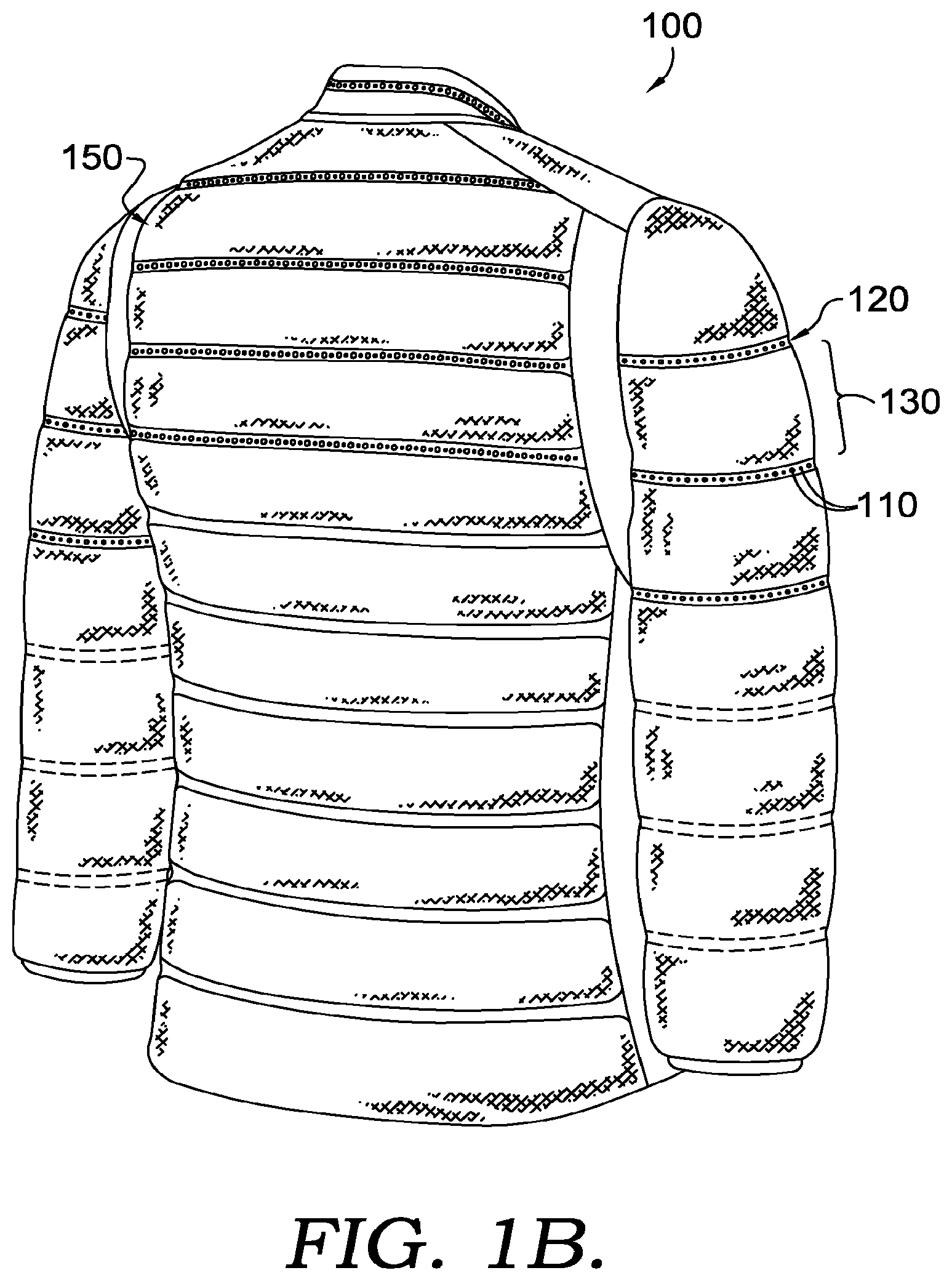
FIGS. 1A and 1B are a front and back view, respectively, of an exemplary cold weather vented garment in accordance with the present invention;
FIG. 2A is a close up view of a section of a venting seam from the cold weather vented garment in FIG. 1A;
FIG. 2B is a close up view of a section of a different example of a venting seam from a cold weather garment in accordance with the present invention;
FIG. 3 is a cross-sectional view of a small section of the cold weather vented garment in FIG. 1, where the insulating chambers are shown in relation to the perforated seams;
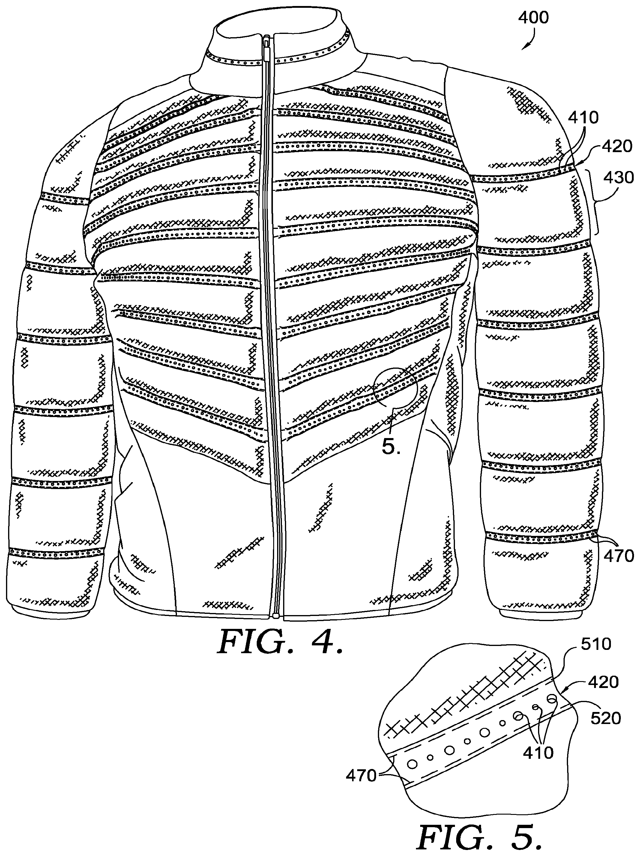
FIG. 4 is a view of a different exemplary cold weather vented garment in accordance with the present invention;
FIG. 5 is a close up view of a section of a venting seam from the cold weather vented garment in FIG. 4;
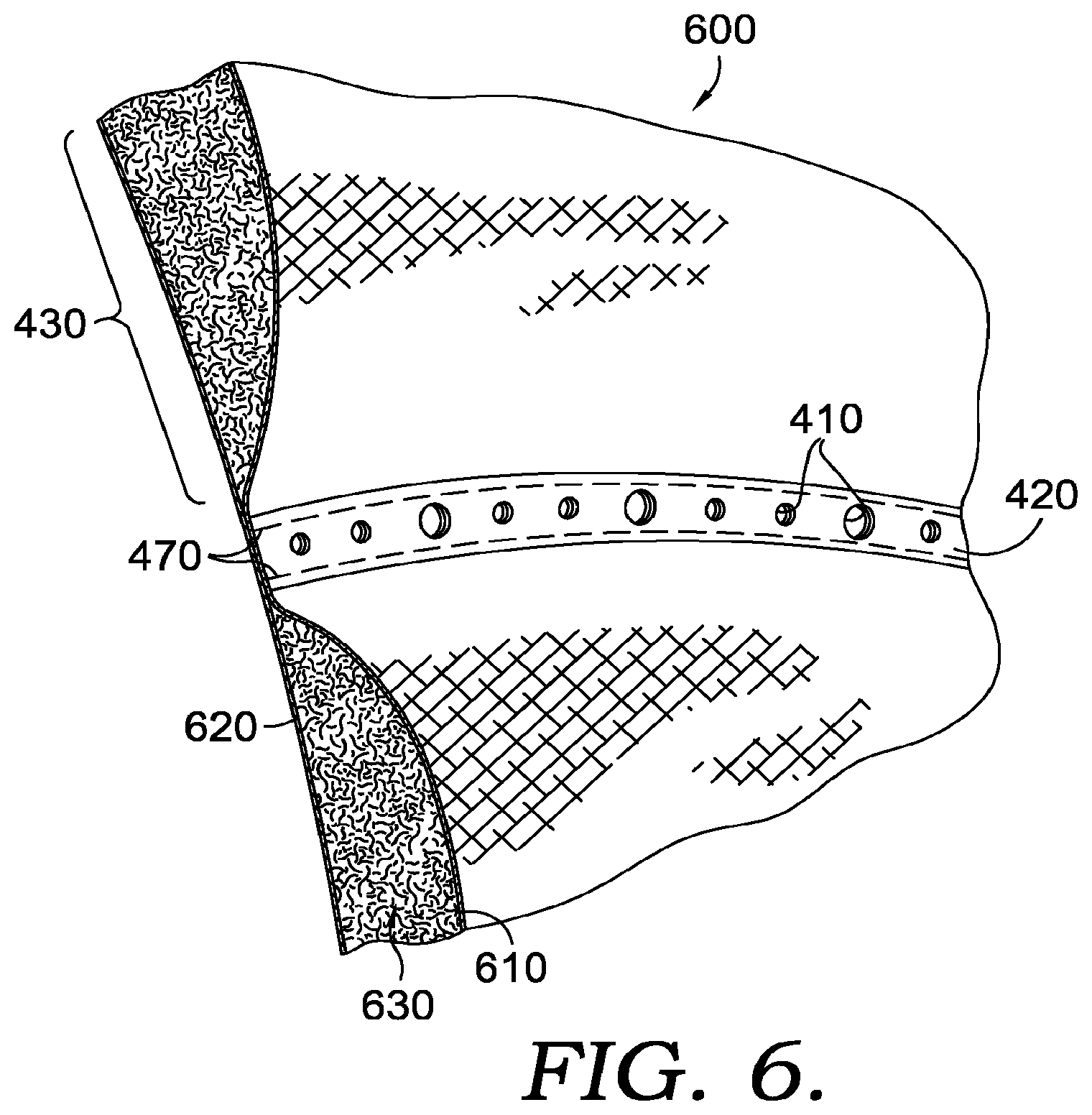
FIG. 6 is a cross-sectional view of a small section of the cold weather vented garment in FIG. 4, where the insulating chambers are shown in relation to the perforated seams; and
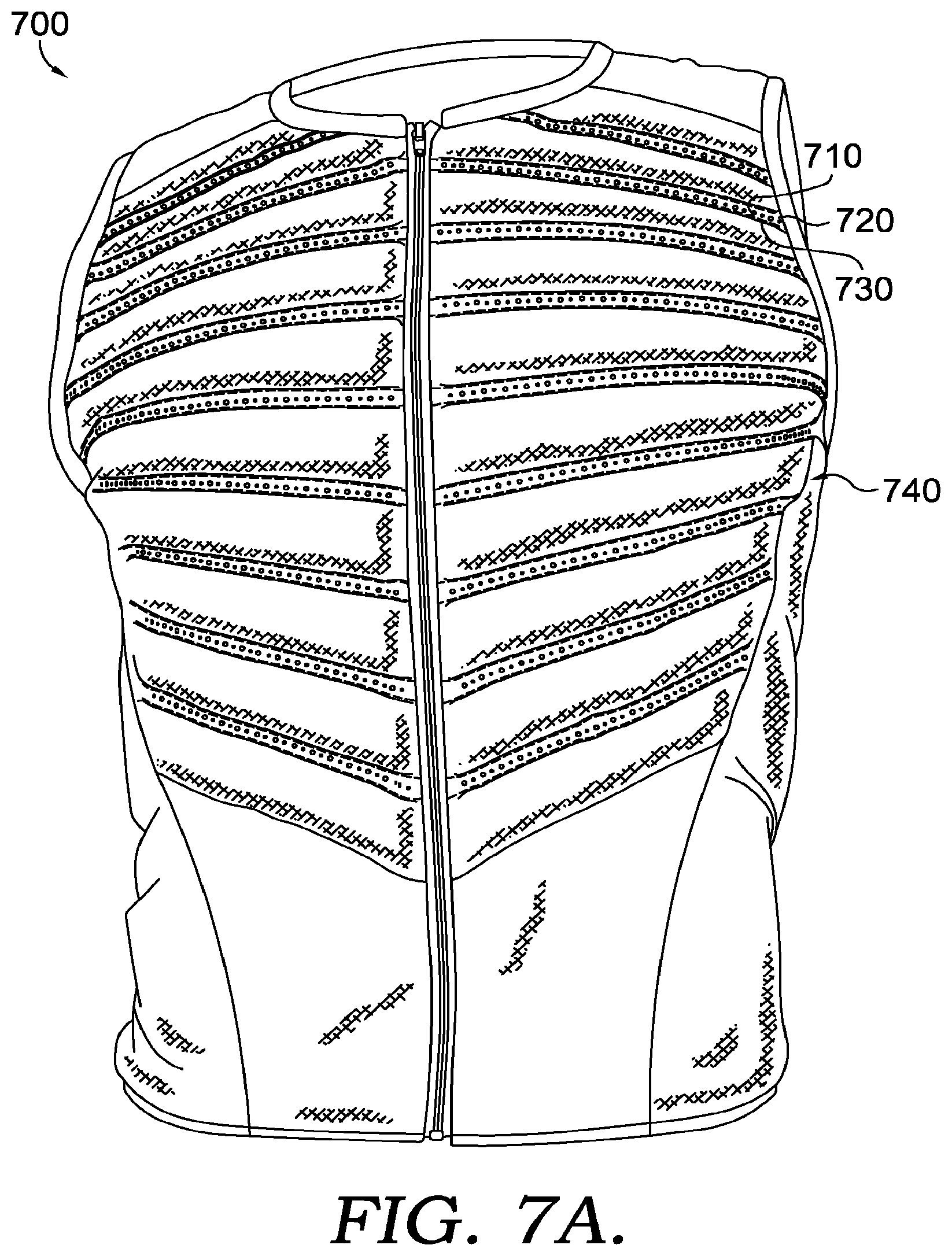
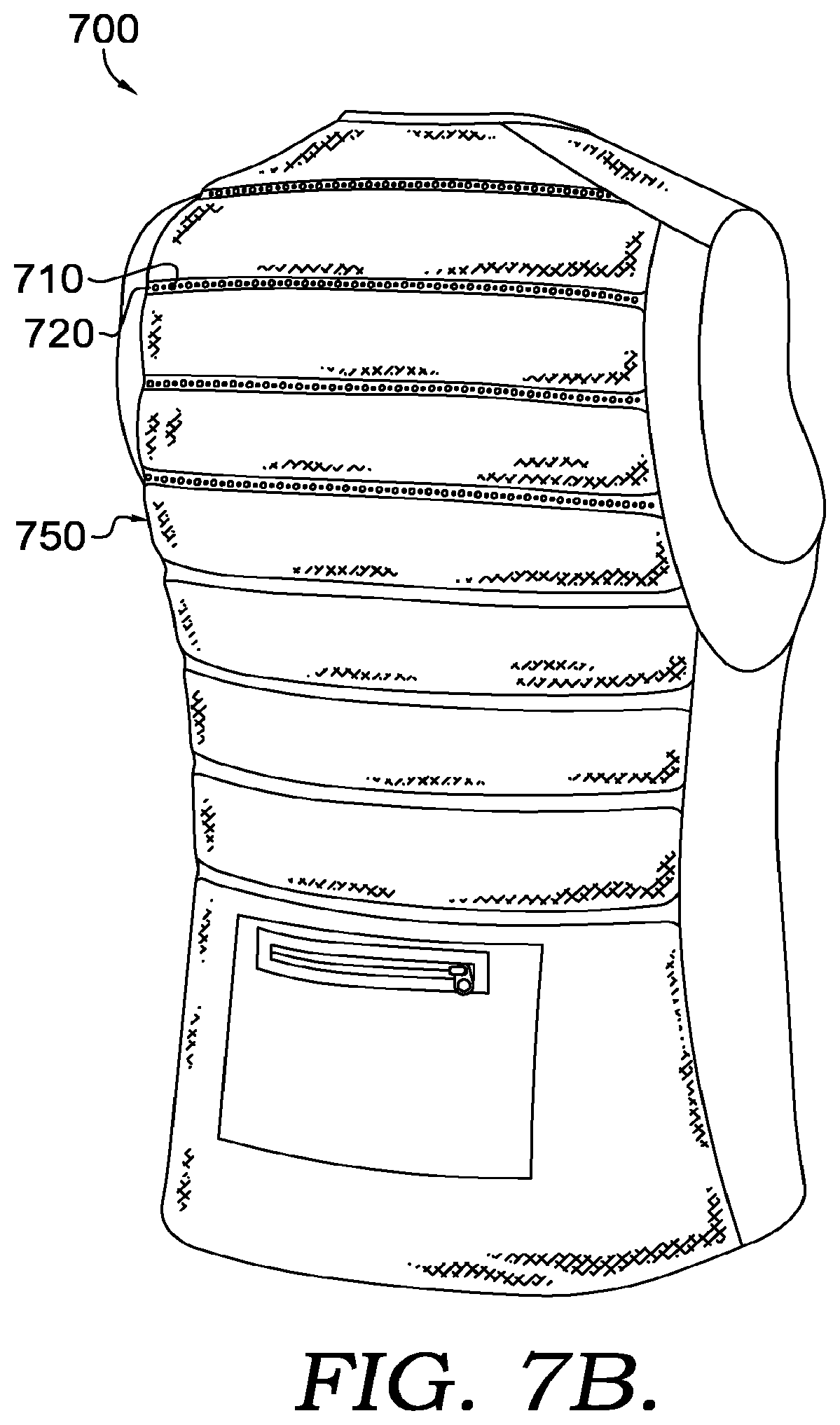
FIGS. 7A and 7B depict front and back view of an additional exemplary cold weather vented garment in accordance with the present invention.
DETAILED DESCRIPTION OF THE INVENTION
FIGS. 1A and 1B are a front view 140 and a back view 150 of a vented cold weather garment 100 in accordance with the present invention. The vented cold weather garment 100 in FIGS. 1A and 1B may be made from conventional synthetic or natural fabrics. The fabrics may be water repellent and fill proof, or alternatively such as in the case of light fabrics, they may need to be treated with waterproofing and down proofing chemicals such as for example, the chemical treatments referred to as DWR (durable water repellent). Since cold weather garments may be down or synthetic thermal fiber filled, an upside of these treatments, is that they prevent the fill from poking through the fabric and, they prevent water moisture from the environment from entering inside of the garment. A downside of these chemical treatments on fabrics, is that these treatments may create a barrier preventing moisture generated from perspiration to evaporate when the vented cold weather garment is in an as-worn configuration.
The vented cold weather garment in FIGS. 1A and 1B may be constructed by cutting out a first inner panel and a corresponding second outer panel, for each section of the garment, from a fabric piece(s) (not shown). An adhesive tape suitable for the particular type of fabric may be placed on the inner face of one of the panels along predetermined sections of the panel to form chambers with the desired shape. Once the adhesive tape is set in place, the second panel may be aligned on top of the panel with the adhesive tape with its inner face facing the tape. Then, the two panels may be pressed together with sufficient force and/or energy applied, to activate the adhesive tape to create a bond(s) between the two panels. The adhesive tape may be activated by heat, or ultrasonic energy, or any other type of applied energy. Once the fabrics are bonded, seams 120 with chambers 130 in between each adhesive taped region are created. The seams 120 may be spaced apart along the length of the garment (as shown), or seams 120 may be spaced apart lengthwise, perpendicular to the length of the garment, along the width of the garment (not shown). The spacing of seams 120 may vary, as may the relative orientation of the seams and/or the shape of the seams, enabling chambers 130 to be different shapes and/or sizes. The chambers 130 may then be filled with down, or synthetic insulating fabrics. Depending on the size and/or shape of the chambers formed, the chambers may be filled with down or thermal insulating fibers, either manually or mechanically. Further, manual filling may be the preferred method if the chambers 130 are relatively small or irregularly shaped. Seams 120 may be perforated during bonding, after bonding, and/or after filling the chambers. Perforations 110 may be formed using a laser, an ultrasonic cutter, and/or a mechanical cutter. The plurality of perforations 110 may provide ventilation and moisture management by allowing moisture vapor from perspiration to escape to the outer environment. Provided the proper equipment, the seams 120 may be simultaneously formed and perforated in a single step, although the seams and perforations may be formed in separate steps without departing from the scope of the present invention.
In a different example of the garment in accordance with the present invention, depending on the fabric material used, the seams 120 may be created without the use of an adhesive tape. For example if the fabric already has adhesive properties, or is weldable by heat, pressure, or ultrasonic energy, the seams 120 may be created and perforated without the use of adhesive tape.
FIG. 2A is a close up of a seam 120. The seams 120 formed as described above, may be presented in a straight line (as shown), in a curved line, in a wavy line, or any other shape that may be useful, for example in forming a chamber, and being visually appealing at the same time. The seams 120 may be mechanically perforated by using a welding and cutting wheel assembly, or may be perforated with a laser, an ultrasonic cutter, and/or a mechanical cutter to form the plurality of perforations 110. The plurality of perforations 110 may be of the same size, or different sizes (as shown). The plurality of perforations maybe of different shapes such as circular (as shown), triangular, rectangular, or any other shape desired. The plurality of perforations 110 may be evenly spaced in a straight line, curvy line, zig-zag, or any other suitable shape for placing the plurality of perforations 110 on seams 120, where the plurality of perforations 110 extend through the seams 120. Additionally, depending on the size of the individual perforations, there may be multiple rows of perforations on each seam. The plurality of perforations 110 may be presented continuously along the seams 120 (as shown), or may be presented intermittently along seams 120, or may be strategically placed only in the areas of high perspiration such as along the back of a wearer, under the arms of a wearer, between the legs of a wearer, etc. The size and frequency of the individual perforations 110 may be determined to provide optimal ventilation and breathability, while still maintaining the structural integrity of the fabric, and maintaining a high level of thermal insulation. For example, the width size of each individual perforation in the plurality of perforations 110 may range anywhere from 0.1 mm-5 mm, and the spacing between each individual perforation measured from edge to edge, may range anywhere from 0.5 mm-10 mm. Other sizes and/or spacing of perforations may be used without departing from the scope of the present invention.
FIG. 2B is a close up of a seam 220. The seams 220 formed as described above, may be presented in a straight line (as shown), in a curved line, in a wavy line, or any other shape that may be useful, for example in forming a chamber, and being visually appealing at the same time. The seams 220 may be mechanically perforated by using a welding and cutting wheel assembly, may be perforated with a laser, an ultrasonic cutter, and/or a mechanical cutter, or may be perforated in any other way to form the plurality of perforations 210. The plurality of perforations 210 may be of the same size (as shown), or different sizes. The plurality of perforations maybe of different shapes such as circular (as shown), triangular, rectangular, or any other shape desired. The plurality of perforations 210 may be evenly spaced in a straight line, curvy line, zig-zag, or any other suitable shape for placing the plurality of perforations 210 on seams 220, where the plurality of perforations 210 extend through the seams 220. Additionally, depending on the size of the individual perforations, there may be multiple rows of perforations on each seam. For example, as seen in FIG. 2B, there may be three rows of perforations 210, wherein the perforations 210 of the middle row may or may not be offset from the perforations of the first and third rows. In the case where the perforations 210 of the middle row are offset (as shown), the offset distance may range anywhere from 0 mm-10 mm, or any other distance suitable for the performance and design desired in the final product. While in the present example, only the middle row is offset, all or none of the rows may be offset or, if more rows of perforations are present, different rows may be chosen to be offset. The plurality of perforations 210 may be presented continuously along the seams 220 (as shown), or may be presented intermittently along seams 220, or may be strategically placed only in the areas of high perspiration such as along the back of a wearer, under the arms of a wearer, between the legs of a wearer, etc. The size and frequency of the individual perforations 210 may be determined to provide a desired level of ventilation and breathability, while still maintaining the structural integrity of the fabric and maintaining a desired level of thermal insulation. For example, a desired amount of ventilation, breathability, structural integrity, and thermal insulation may be achieved in a garment using light fabric/textile and down fill with a width size of each individual perforation in the plurality of perforations 210 ranging anywhere from 0.1 mm-5 mm, and the spacing between each individual perforation measured from edge to edge ranging anywhere from 0.5 mm-10 mm, although other sizes and configurations are within the scope of the present invention.
One way of measuring the amount of breathability of a garment, such as garments in accordance with the present invention, may be by performing a hot-plate transfer test, which allows for measurement of the resistance to evaporative transfer of a textile or garment. The lower the resistance number obtained from the test, the less resistance to evaporation there is and therefore, the more evaporation that occurs through the garment in a given amount of time. Garments in accordance with the present invention may be shown to have lower resistance to evaporative transfer than un-perforated garments in hot-plate transfer testing.
The garment construction may become more apparent in reference to FIG. 3, where an angled cross-sectional view 300 of a small section of the garment with all the novel features, is shown. The garment in accordance with the present invention may be constructed from a first inner panel 310 and a second outer panel 320. The seams 120 and chambers 130 may be created as described above in reference to FIGS. 1A and 1B, where the chambers 130 are created between pairs of seams 120 between the first inner panel 310 and the first outer panel 320. The plurality of perforations 110 extend through the first inner panel 310 and the second outer panel 320 to provide ventilation and moisture management by allowing moisture vapor from perspiration to escape to the outer environment when the vented cold weather garment is in an as-worn configuration. The chambers 130 may then be filled with a fill 330, such as down or synthetic fibers.
Now, in reference to FIG. 4, a front view of a different cold weather garment 400 in accordance with the present invention is provided. Like the cold weather garment 100 of FIGS. 1A and 1B, the vented cold weather garment 100 in FIG. 4 may be made from conventional synthetic or natural fabrics. The fabrics may be water repellent and down proof, or alternatively such as in the case of ultra-light fabrics (29 g/m.sup.2 or lower) and light weight fabrics (89 g/m.sup.2-30 g/m.sup.2), the fabrics may need to be treated with waterproofing and down proofing chemicals such as for example, the chemical treatments referred to as DWR (durable water repellent).
The cold weather garment in FIG. 4 may be constructed in a fashion similar to that described above with regard to the garment shown in FIGS. 1A and 1B to form seams 420 to create chambers to hold fill material, with a plurality of perforations 410 formed in seams 420. The seams 420 may be further reinforced by adding stitching 470 along their upper edge/boundary 510 and/or lower edge/boundary 520, as can be seen in the close up view of FIG. 5.
Stitching 470 may be applied mechanically and/or by hand, and may use any type of thread, whether natural or synthetic. Stitching 470 may be applied before or after applying pressure and/or energy to form seams 420. Likewise, stitching 470 may be applied before or after perforations 410 and/or before or after chambers 430 are filled.
The garment construction may become more apparent in reference to FIG. 6, where an angled cross-sectional view 600 of a small section of the garment with all the novel features, is shown. The garment in accordance with the present invention may be constructed from a first inner panel 620 and a second outer panel 610. The seams 420 and chambers 430 may be created as described above in reference to FIG. 4. The chambers may then be filled with fill 630, such as down or synthetic fibers.
Alternatively, in a further different example of the garment in accordance with the present invention, the seams 420 may be produced by omitting the adhesive tape layer altogether. In other words, the seams 420 may be created simply by stitching 470 along the upper seam boundary 510 and lower seam boundary 520. The plurality of perforations 410 may then be placed in between the stitched boundaries. This example may be pictured better in reference to FIG. 5.
The insulating chambers in the garments in accordance with the present invention may be formed by welding separate pieces of fabric at each seam, or as discussed earlier, may be formed by pressing two whole panels with adhesive tape in strategic places in between the two panels. If the chambers were formed by welding separate pieces of fabric at each seam, this would allow for the introduction of different textures, colors, or functionalities by introducing different types of fabrics at different sections of the garment.
Further, the vented cold weather insulating garment examples shown in the examples of FIGS. 1A, 1B, and FIG. 4 are vented cold weather jackets or coats. However, the insulating vented garments in accordance with the present invention may also be constructed in the form of vests, pants, overalls, gloves, hats, etc. FIGS. 7A and 7B depict an example vest 700 in accordance with the present invention, with FIG. 7A depicting a front view 740 and FIG. 7B depicting a back view 750 of the exemplary vest 700. As seen in FIGS. 7A and 7B, the vest 700 may have seams 720 with a plurality of perforations 710, forming thermally insulating chambers 740, which may be filled with down, or any other thermally insulating material, such as polyester fibers. The vest 700 may or may not have stitches along the edges of seams 720 for reinforcement of the seams. The vest 700 may be used as a light weight breathable thermal insulation garment, for example by a runner.
From the foregoing, it will be seen that this invention is one well adapted to attain all the ends and objects hereinabove set forth together with other advantages which are obvious and which are inherent to the structure.
It will be understood that certain features and subcombinations are of utility and may be employed without reference to other features and subcombinations. This is contemplated by and is within the scope of the claims.
Since many possible embodiments may be made of the invention without departing from the scope thereof, it is to be understood that all matter herein set forth or shown in the accompanying drawings is to be interpreted as illustrative and not in a limiting sense.
* * * * *
References
-
nike.com/us/en_us/c/running/aeroloft
-
seasonsoutfitters.com/index.php/outerwear-32/waterproof/78678-pursuitladies-3-layer-light-bonded-hybrid-soft-shell-jacket-with-laser-perforation.html
-
mec.ca/product/5038-526/mavic-helium-jacket-mens
-
runningwarehouse.com/Salomon_Mens_S-Lab_Hybrid_Jacket/descpage-SMSLHJ.html
-
thenorthface.com/catalog/sc-gear/women-39-s-better-than-nakedcool-jacket.html
-
ashcity.com/en-ca/products/outerwear/insulated-seam-sealed/88680-ventilate-mens-nbsp-3bseam-sealed-insulated-jacket.html
-
houdinisportswear.com/en/women/womens-c9-loft-jacket
-
shop.nordstrom.com/s/akris-punto-laser-perforated-jacket/3667112
-
marmot.com/products/details/greenland-baffled-jacket
-
-
backcountry.com/rab-microlight-alpine-down-jacketwomens?CMP_SKU=RAB0244&MER=0406&skid=RAB0244-ORC-USXLUS16
-
oldnavy.gap.com/browse/product.do?vid=1&pid=172238002
-
-
-
coveredbridgecyclery.com/barbour-mens-chukka-quilted-jacket-militarybrown-navy-1423.html
-
youlookfab.com/2013/07/15/trend-quilted-textures
D00000
D00001
D00002
D00003
D00004
D00005
D00006
D00007
XML
uspto.report is an independent third-party trademark research tool that is not affiliated, endorsed, or sponsored by the United States Patent and Trademark Office (USPTO) or any other governmental organization. The information provided by uspto.report is based on publicly available data at the time of writing and is intended for informational purposes only.
While we strive to provide accurate and up-to-date information, we do not guarantee the accuracy, completeness, reliability, or suitability of the information displayed on this site. The use of this site is at your own risk. Any reliance you place on such information is therefore strictly at your own risk.
All official trademark data, including owner information, should be verified by visiting the official USPTO website at www.uspto.gov. This site is not intended to replace professional legal advice and should not be used as a substitute for consulting with a legal professional who is knowledgeable about trademark law.