Cleaning method for a robotic cleaning device
Haegermarck , et al.
U.S. patent number 10,678,251 [Application Number 15/535,506] was granted by the patent office on 2020-06-09 for cleaning method for a robotic cleaning device. This patent grant is currently assigned to Aktiebolaget Electrolux. The grantee listed for this patent is Aktiebolaget Electrolux. Invention is credited to Anders Haegermarck, Magnus Lindhe.


| United States Patent | 10,678,251 |
| Haegermarck , et al. | June 9, 2020 |
Cleaning method for a robotic cleaning device
Abstract
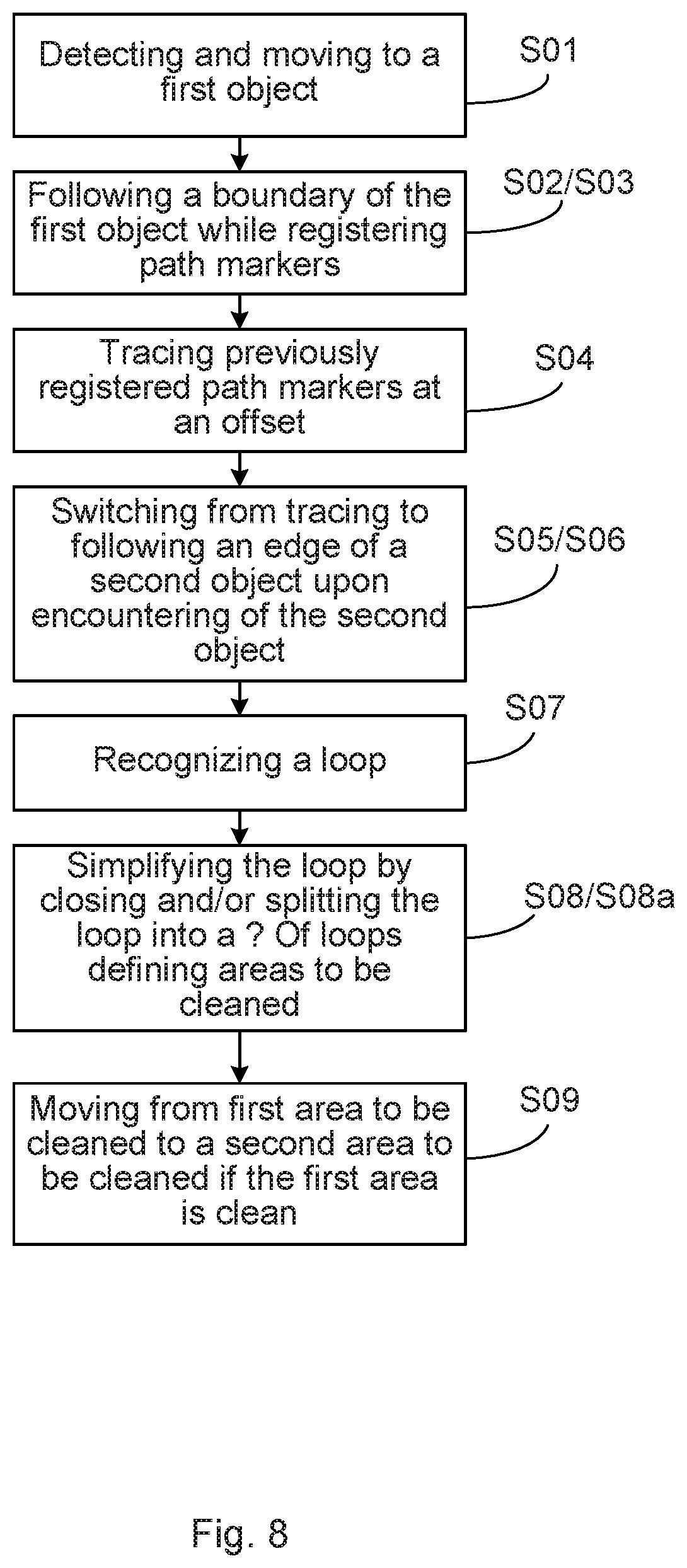
A method of operating a robotic cleaning device over a surface to be cleaned, the method being performed by the robotic cleaning device. The method includes: following a boundary of a first object while registering path markers including positional information at intervals on the surface; tracing previously registered path markers at an offset upon encountering one or more of the previously registered path markers; and switching from tracing the previously registered path markers to following an edge of a second object upon detection of the second object.
| Inventors: | Haegermarck; Anders (Trangsund, SE), Lindhe; Magnus (Stockholm, SE) | ||||||||||
|---|---|---|---|---|---|---|---|---|---|---|---|
| Applicant: |
|
||||||||||
| Assignee: | Aktiebolaget Electrolux
(Stockholm, SE) |
||||||||||
| Family ID: | 52144680 | ||||||||||
| Appl. No.: | 15/535,506 | ||||||||||
| Filed: | December 16, 2014 | ||||||||||
| PCT Filed: | December 16, 2014 | ||||||||||
| PCT No.: | PCT/EP2014/077954 | ||||||||||
| 371(c)(1),(2),(4) Date: | June 13, 2017 | ||||||||||
| PCT Pub. No.: | WO2016/095966 | ||||||||||
| PCT Pub. Date: | June 23, 2016 |
Prior Publication Data
| Document Identifier | Publication Date | |
|---|---|---|
| US 20170344013 A1 | Nov 30, 2017 | |
| Current U.S. Class: | 1/1 |
| Current CPC Class: | G05D 1/0274 (20130101); A47L 11/24 (20130101); A47L 11/4061 (20130101); G05D 1/0219 (20130101); G05D 1/0238 (20130101); A47L 11/4011 (20130101); G05D 1/0234 (20130101); A47L 11/28 (20130101); A47L 9/0477 (20130101); A47L 5/22 (20130101); A47L 9/2852 (20130101); A47L 9/0411 (20130101); A47L 9/2826 (20130101); A47L 9/009 (20130101); A47L 2201/04 (20130101); G05D 1/0272 (20130101); G05D 2201/0215 (20130101) |
| Current International Class: | A47L 11/24 (20060101); A47L 11/28 (20060101); G05D 1/02 (20200101); A47L 9/04 (20060101); A47L 5/22 (20060101); A47L 9/00 (20060101); A47L 11/40 (20060101); A47L 9/28 (20060101) |
References Cited [Referenced By]
U.S. Patent Documents
| 1286321 | December 1918 | Hoover |
| 1401007 | December 1921 | Staples |
| 3010129 | November 1961 | Moore |
| 3233274 | February 1966 | Kroll |
| 3550714 | December 1970 | Bellinger |
| 3570227 | March 1971 | Bellinger |
| 3713505 | January 1973 | Muller |
| 3837028 | September 1974 | Bridge |
| 4028765 | June 1977 | Liebscher |
| 4036147 | July 1977 | Westling |
| 4114711 | September 1978 | Wilkins |
| 4119900 | October 1978 | Kremnitz |
| 4306174 | December 1981 | Mourier |
| 4306329 | December 1981 | Yokoi |
| 4369543 | January 1983 | Chen |
| 4502173 | March 1985 | Patzold |
| 4627511 | December 1986 | Yajima |
| 4647209 | March 1987 | Neukomm |
| 4800978 | January 1989 | Wasa |
| 4822450 | April 1989 | Davis |
| 4825091 | April 1989 | Breyer |
| 4836905 | June 1989 | Davis |
| 4838990 | June 1989 | Jucha |
| 4842686 | June 1989 | Davis |
| 4849067 | July 1989 | Jucha |
| 4854000 | August 1989 | Takimoto |
| 4864511 | September 1989 | Moy |
| 4872938 | October 1989 | Davis |
| 4878003 | October 1989 | Knepper |
| 4886570 | December 1989 | Davis |
| 4918607 | April 1990 | Wible |
| 4919224 | April 1990 | Shyu |
| 4922559 | May 1990 | Wall |
| 4959192 | September 1990 | Trundle |
| 4962453 | October 1990 | Pong |
| 4989818 | February 1991 | Trundle |
| 5001635 | March 1991 | Yasutomi |
| 5006302 | April 1991 | Trundle |
| 5023444 | June 1991 | Ohman |
| 5032775 | July 1991 | Mizuno |
| 5034673 | July 1991 | Shoji |
| 5042861 | August 1991 | Trundle |
| 5045118 | September 1991 | Mason |
| 5086535 | February 1992 | Grossmeyer |
| 5095577 | March 1992 | Jonas |
| 5107946 | April 1992 | Kamimura |
| 5155683 | October 1992 | Rahim |
| 5243732 | September 1993 | Koharagi |
| 5245177 | September 1993 | Schiller |
| 5276933 | January 1994 | Hennessey |
| 5279672 | January 1994 | Betker |
| 5293955 | March 1994 | Lee |
| 5307273 | April 1994 | Oh |
| 5309592 | May 1994 | Hiratsuka |
| 5341540 | August 1994 | Soupert |
| 5345639 | September 1994 | Tanoue |
| 5349378 | September 1994 | Maali |
| 5353224 | October 1994 | Lee |
| 5367458 | November 1994 | Roberts et al. |
| 5369347 | November 1994 | Yoo |
| 5377106 | December 1994 | Drunk |
| 5390627 | February 1995 | van der Berg |
| 5398632 | March 1995 | Goldbach |
| 5402051 | March 1995 | Fujiwara |
| 5440216 | August 1995 | Kim |
| 5444965 | August 1995 | Colens |
| 5446356 | August 1995 | Kim |
| 5454129 | October 1995 | Kell |
| 5518552 | May 1996 | Tanoue |
| 5534762 | July 1996 | Kim |
| 5548511 | August 1996 | Bancroft |
| 5560077 | October 1996 | Crotchett |
| 5568589 | October 1996 | Hwang |
| 5621291 | April 1997 | Lee |
| 5646494 | July 1997 | Han |
| 5666689 | September 1997 | Andersen |
| 5682313 | October 1997 | Edlund |
| 5682640 | November 1997 | Han |
| 5687294 | November 1997 | Jeong |
| 5698957 | December 1997 | Sowada |
| 5745946 | May 1998 | Thrasher |
| 5758298 | May 1998 | Guldner |
| 5778554 | July 1998 | Jones |
| 5781960 | July 1998 | Kilstrom |
| 5787545 | August 1998 | Colens |
| 5815880 | October 1998 | Nakanishi |
| 5825981 | October 1998 | Matsuda |
| 5841259 | November 1998 | Kim |
| 5852984 | December 1998 | Matsuyama |
| 5867800 | February 1999 | Leif |
| 5890250 | April 1999 | Lange |
| 5896488 | April 1999 | Jeong |
| 5903124 | May 1999 | Kawakami |
| 5926909 | July 1999 | McGee |
| 5933902 | August 1999 | Frey |
| 5935179 | August 1999 | Kleiner |
| 5940927 | August 1999 | Haegermarck |
| 5942869 | August 1999 | Katou |
| 5947051 | September 1999 | Geiger |
| 5959423 | September 1999 | Nakanishi |
| 5959424 | September 1999 | Elkmann |
| 5966765 | October 1999 | Hamada |
| RE36391 | November 1999 | van den Berg |
| 5983833 | November 1999 | van der Lely |
| 5987696 | November 1999 | Wang |
| 5991951 | November 1999 | Kubo |
| 5995884 | November 1999 | Allen |
| 5997670 | December 1999 | Walter |
| 5999865 | December 1999 | Bloomquist et al. |
| 6012470 | January 2000 | Jones |
| 6024107 | February 2000 | Jones |
| 6064926 | May 2000 | Sarangapani |
| 6076662 | June 2000 | Bahten |
| 6082377 | July 2000 | Frey |
| 6124694 | September 2000 | Bancroft |
| 6142252 | November 2000 | Kinto |
| 6176067 | January 2001 | Bahten |
| 6213136 | April 2001 | Jones |
| 6226830 | May 2001 | Hendriks |
| 6230360 | May 2001 | Singleton |
| 6240342 | May 2001 | Fiegert |
| 6251551 | June 2001 | Kunze-Concewitz |
| 6255793 | July 2001 | Peless |
| 6263989 | July 2001 | Won |
| 6300737 | October 2001 | Bergvall |
| 6311366 | November 2001 | Sepke |
| 6327741 | December 2001 | Reed |
| 6339735 | January 2002 | Peless |
| 6358325 | March 2002 | Andreas |
| 6360801 | March 2002 | Walter |
| 6370452 | April 2002 | Pfister |
| 6370453 | April 2002 | Sommer |
| 6381801 | May 2002 | Clemons, Sr. |
| 6389329 | May 2002 | Colens |
| 6413149 | July 2002 | Wada |
| 6417641 | July 2002 | Peless |
| 6431296 | August 2002 | Won |
| 6438456 | August 2002 | Feddema |
| 6443509 | September 2002 | Levin |
| 6457199 | October 2002 | Frost |
| 6457206 | October 2002 | Judson |
| 6459955 | October 2002 | Bartsch |
| 6465982 | October 2002 | Bergvall |
| 6481515 | November 2002 | Kirkpatrick |
| 6482678 | November 2002 | Frost |
| 6493612 | December 2002 | Bisset |
| 6493613 | December 2002 | Peless |
| 6496754 | December 2002 | Song |
| 6504610 | January 2003 | Bauer |
| 6519804 | February 2003 | Vujik |
| 6525509 | February 2003 | Petersson |
| D471243 | March 2003 | Cioffi |
| 6532404 | March 2003 | Colens |
| 6535793 | March 2003 | Allard |
| 6571415 | June 2003 | Gerber |
| 6580246 | June 2003 | Jacobs |
| 6581239 | June 2003 | Dyson |
| 6594844 | July 2003 | Jones |
| 6597143 | July 2003 | Song |
| 6601265 | August 2003 | Burlington |
| 6605156 | August 2003 | Clark |
| 6609962 | August 2003 | Wakabayashi |
| 6611120 | August 2003 | Song |
| 6611318 | August 2003 | LaPolice |
| 6615108 | September 2003 | Peless |
| 6615885 | September 2003 | Ohm |
| 6633150 | October 2003 | Wallach |
| 6637446 | October 2003 | Frost |
| 6658325 | December 2003 | Zweig |
| 6661239 | December 2003 | Ozick |
| 6662889 | December 2003 | De Fazio |
| 6667592 | December 2003 | Jacobs |
| 6668951 | December 2003 | Won |
| 6671592 | December 2003 | Bisset |
| 6690134 | February 2004 | Jones |
| 6726823 | April 2004 | Wang |
| 6732826 | May 2004 | Song |
| 6745431 | June 2004 | Dijksman |
| 6748297 | June 2004 | Song |
| 6769004 | July 2004 | Barrett |
| 6774596 | August 2004 | Bisset |
| 6775871 | August 2004 | Finch |
| 6781338 | August 2004 | Jones |
| 6809490 | October 2004 | Jones |
| 6810305 | October 2004 | Kirkpatrick, Jr. |
| 6820801 | November 2004 | Kaneko |
| 6841963 | January 2005 | Song |
| 6845297 | January 2005 | Allard |
| 6850024 | February 2005 | Peless |
| 6859010 | February 2005 | Jeon |
| 6859976 | March 2005 | Plankenhorn |
| 6860206 | March 2005 | Rudakevych |
| 6868307 | March 2005 | Song |
| 6869633 | March 2005 | Sus |
| 6870792 | March 2005 | Chiappetta |
| 6882334 | April 2005 | Meyer |
| 6883201 | April 2005 | Jones |
| 6885912 | April 2005 | Peless |
| 6901624 | June 2005 | Mori |
| 6925679 | August 2005 | Wallach |
| D510066 | September 2005 | Hickey |
| 6938298 | September 2005 | Aasen |
| 6939208 | September 2005 | Kamimura |
| 6940291 | September 2005 | Ozick |
| 6941199 | September 2005 | Bottomley |
| 6942548 | September 2005 | Wada |
| 6956348 | October 2005 | Landry |
| 6957712 | October 2005 | Song |
| 6964312 | November 2005 | Maggio |
| 6965209 | November 2005 | Jones |
| 6967275 | November 2005 | Ozick |
| 6971140 | December 2005 | Kim |
| 6971141 | December 2005 | Tak |
| 6984952 | January 2006 | Peless |
| 7000623 | February 2006 | Welsh |
| 7004269 | February 2006 | Song |
| 7013200 | March 2006 | Wakui |
| 7013527 | March 2006 | Thomas, Sr. |
| 7015831 | March 2006 | Karlsson |
| 7024278 | April 2006 | Chiappetta |
| 7031805 | April 2006 | Lee |
| 7040968 | May 2006 | Kamimura |
| 7042342 | May 2006 | Luo |
| 7043794 | May 2006 | Conner |
| 7050926 | May 2006 | Theurer et al. |
| 7053578 | May 2006 | Diehl et al. |
| 7053580 | May 2006 | Aldred |
| 7054716 | May 2006 | McKee |
| 7059012 | June 2006 | Song |
| 7079923 | July 2006 | Abramson |
| 7082350 | July 2006 | Skoog |
| D526753 | August 2006 | Tani |
| 7085624 | August 2006 | Aldred |
| 7103449 | September 2006 | Woo |
| 7113847 | September 2006 | Chmura |
| 7117067 | October 2006 | McLurkin |
| 7133745 | November 2006 | Wang |
| 7134164 | November 2006 | Alton |
| 7135992 | November 2006 | Karlsson |
| 7143696 | December 2006 | Rudakevych |
| 7145478 | December 2006 | Goncalves |
| 7150068 | December 2006 | Ragner |
| 7155308 | December 2006 | Jones |
| 7155309 | December 2006 | Peless |
| 7162338 | January 2007 | Goncalves |
| 7167775 | January 2007 | Abramson |
| 7173391 | February 2007 | Jones |
| 7174238 | February 2007 | Zweig |
| 7177737 | February 2007 | Karlsson |
| 7184586 | February 2007 | Jeon |
| 7185396 | March 2007 | Im |
| 7185397 | March 2007 | Stuchlik |
| 7188000 | March 2007 | Chiappetta |
| 7196487 | March 2007 | Jones |
| 7199711 | April 2007 | Field |
| 7200892 | April 2007 | Kim |
| 7202630 | April 2007 | Dan |
| 7206677 | April 2007 | Hulden |
| 7207081 | April 2007 | Gerber |
| 7208892 | April 2007 | Tondra |
| 7213298 | May 2007 | Cipolla |
| 7213663 | May 2007 | Kim |
| 7222390 | May 2007 | Cipolla |
| 7225500 | June 2007 | Diehl |
| 7237298 | July 2007 | Reindle |
| 7240396 | July 2007 | Thomas, Sr. |
| 7246405 | July 2007 | Yan |
| 7248951 | July 2007 | Hulden |
| 7251853 | August 2007 | Park |
| 7254464 | August 2007 | McLurkin |
| 7254859 | August 2007 | Gerber |
| 7269877 | September 2007 | Tondra |
| 7272467 | September 2007 | Goncalves |
| 7272868 | September 2007 | Im |
| 7274167 | September 2007 | Kim |
| 7275280 | October 2007 | Haegermarck |
| 7288912 | October 2007 | Landry |
| D556961 | December 2007 | Swyst |
| 7303776 | December 2007 | Sus |
| 7324870 | January 2008 | Lee |
| 7331436 | February 2008 | Pack |
| 7332890 | February 2008 | Cohen |
| 7343221 | March 2008 | Ann |
| 7343719 | March 2008 | Sus |
| 7346428 | March 2008 | Huffman |
| 7349759 | March 2008 | Peless |
| 7359766 | April 2008 | Jeon |
| 7363994 | April 2008 | DeFazio |
| 7369460 | May 2008 | Chiappetta |
| 7372004 | May 2008 | Buchner |
| 7388343 | June 2008 | Jones |
| 7389156 | June 2008 | Ziegler |
| 7389166 | June 2008 | Harwig |
| 7403360 | July 2008 | Cunningham |
| 7412748 | August 2008 | Lee |
| 7417404 | August 2008 | Lee |
| 7418762 | September 2008 | Arai |
| 7424766 | September 2008 | Reindle |
| 7429843 | September 2008 | Jones |
| 7430455 | September 2008 | Casey |
| 7438766 | October 2008 | Song |
| 7441298 | October 2008 | Svendsen |
| 7444206 | October 2008 | Abramson |
| 7448113 | November 2008 | Jones |
| 7459871 | December 2008 | Landry |
| 7464157 | December 2008 | Okude |
| 7474941 | January 2009 | Kim |
| 7480958 | January 2009 | Song |
| 7480960 | January 2009 | Kim |
| D586959 | February 2009 | Geringer |
| 7489277 | February 2009 | Sung |
| 7489985 | February 2009 | Ko |
| 7499774 | March 2009 | Barrett |
| 7499775 | March 2009 | Filippov |
| 7499776 | March 2009 | Allard |
| 7499804 | March 2009 | Svendsen |
| 7503096 | March 2009 | Lin |
| 7515991 | April 2009 | Egawa |
| D593265 | May 2009 | Carr |
| 7539557 | May 2009 | Yamauchi |
| 7546891 | June 2009 | Won |
| 7546912 | June 2009 | Pack |
| 7555363 | June 2009 | Augenbraun |
| 7556108 | July 2009 | Won |
| 7559269 | July 2009 | Rudakevych |
| 7564571 | July 2009 | Karabassi |
| 7566839 | July 2009 | Hukuba |
| 7567052 | July 2009 | Jones |
| 7568259 | August 2009 | Yan |
| 7568536 | August 2009 | Yu |
| 7571511 | August 2009 | Jones |
| 7573403 | August 2009 | Goncalves |
| 7574282 | August 2009 | Petersson |
| 7578020 | August 2009 | Jaworski |
| 7579803 | August 2009 | Jones |
| 7581282 | September 2009 | Woo |
| 7597162 | October 2009 | Won |
| 7600521 | October 2009 | Woo |
| 7600593 | October 2009 | Filippov |
| 7603744 | October 2009 | Reindle |
| 7604675 | October 2009 | Makarov |
| 7610651 | November 2009 | Baek |
| 7613543 | November 2009 | Petersson |
| 7620476 | November 2009 | Morse |
| 7636982 | December 2009 | Jones |
| 7647144 | January 2010 | Haegermarck |
| 7650666 | January 2010 | Jang |
| 7654348 | February 2010 | Ohm |
| 7660650 | February 2010 | Kawagoe |
| 7663333 | February 2010 | Jones |
| 7673367 | March 2010 | Kim |
| 7679532 | March 2010 | Karlsson |
| 7688676 | March 2010 | Chiappetta |
| 7693654 | April 2010 | Dietsch |
| 7697141 | April 2010 | Jones |
| 7706917 | April 2010 | Chiappetta |
| 7706921 | April 2010 | Jung |
| 7709497 | May 2010 | Christensen, IV |
| 7711450 | May 2010 | Im |
| 7720572 | May 2010 | Ziegler |
| 7721829 | May 2010 | Lee |
| 7729801 | June 2010 | Abramson |
| 7749294 | July 2010 | Oh |
| 7751940 | July 2010 | Lee |
| 7761954 | July 2010 | Ziegler |
| 7765635 | August 2010 | Park |
| 7765638 | August 2010 | Pineschi |
| 7769490 | August 2010 | Abramson |
| 7774158 | August 2010 | Domingues Goncalves |
| 7779504 | August 2010 | Lee |
| 7780796 | August 2010 | Shim |
| 7784139 | August 2010 | Sawalski |
| 7784570 | August 2010 | Couture |
| 7785544 | August 2010 | Alward |
| 7787991 | August 2010 | Jeung |
| 7793614 | September 2010 | Ericsson |
| 7801645 | September 2010 | Taylor |
| 7805220 | September 2010 | Taylor |
| 7827653 | November 2010 | Liu |
| 7832048 | November 2010 | Harwig |
| 7835529 | November 2010 | Hernandez |
| 7843431 | November 2010 | Robbins |
| 7844364 | November 2010 | McLurkin |
| 7849555 | December 2010 | Hahm |
| 7856291 | December 2010 | Jung |
| 7860608 | December 2010 | Lee |
| 7861365 | January 2011 | Sun |
| 7861366 | January 2011 | Hahm |
| 7873437 | January 2011 | Aldred |
| 7877166 | January 2011 | Harwig |
| 7886399 | February 2011 | Dayton |
| 7890210 | February 2011 | Choi |
| 7891045 | February 2011 | Kim |
| 7891289 | February 2011 | Day |
| 7891446 | February 2011 | Couture |
| 7894951 | February 2011 | Norris |
| 7916931 | March 2011 | Lee |
| 7920941 | April 2011 | Park |
| 7921506 | April 2011 | Baek |
| 7926598 | April 2011 | Rudakevych |
| 7934571 | May 2011 | Chiu |
| 7937800 | May 2011 | Yan |
| 7942107 | May 2011 | Vosburgh |
| 7957837 | June 2011 | Ziegler |
| 7962997 | June 2011 | Chung |
| 7966339 | June 2011 | Kim |
| 7975790 | July 2011 | Kim |
| 7979175 | July 2011 | Allard |
| 7979945 | July 2011 | Dayton |
| 7981455 | July 2011 | Sus |
| 7997118 | August 2011 | Mecca |
| 8001651 | August 2011 | Chang |
| 8007221 | August 2011 | More |
| 8010229 | August 2011 | Kim |
| 8019223 | September 2011 | Hudson |
| 8020657 | September 2011 | Allard |
| 8032978 | October 2011 | Haegermarck |
| 8034390 | October 2011 | Sus |
| 8042663 | October 2011 | Pack |
| 8046103 | October 2011 | Abramson |
| 8061461 | November 2011 | Couture |
| 8065778 | November 2011 | Kim |
| 8073439 | December 2011 | Stromberg |
| 8074752 | December 2011 | Rudakevych |
| 8078338 | December 2011 | Pack |
| 8079432 | December 2011 | Ohm |
| 8082836 | December 2011 | More |
| 8086419 | December 2011 | Goncalves |
| 8087117 | January 2012 | Kapoor |
| 8095238 | January 2012 | Jones |
| 8095336 | January 2012 | Goncalves |
| 8107318 | January 2012 | Chiappetta |
| 8108092 | January 2012 | Phillips |
| 8109191 | February 2012 | Rudakevych |
| 8112942 | February 2012 | Bohm |
| 8113304 | February 2012 | Won |
| 8122982 | February 2012 | Morey |
| 8127396 | March 2012 | Mangiardi |
| 8127399 | March 2012 | Dilger |
| 8127704 | March 2012 | Vosburgh |
| 8136200 | March 2012 | Splinter |
| 8150650 | April 2012 | Goncalves |
| D659311 | May 2012 | Geringer |
| 8166904 | May 2012 | Israel |
| 8195333 | June 2012 | Ziegler |
| 8196251 | June 2012 | Lynch |
| 8199109 | June 2012 | Robbins |
| 8200600 | June 2012 | Rosenstein |
| 8200700 | June 2012 | Moore |
| 8237389 | August 2012 | Fitch |
| 8237920 | August 2012 | Jones |
| 8239992 | August 2012 | Schnittman |
| 8244469 | August 2012 | Cheung |
| 8253368 | August 2012 | Landry |
| 8255092 | August 2012 | Phillips |
| 8256542 | September 2012 | Couture |
| 8265793 | September 2012 | Cross |
| 8274406 | September 2012 | Karlsson |
| 8281703 | October 2012 | Moore |
| 8281731 | October 2012 | Vosburgh |
| 8290619 | October 2012 | McLurkin |
| 8292007 | October 2012 | DeFazio |
| 8295125 | October 2012 | Chiappetta |
| D670877 | November 2012 | Geringer |
| 8308529 | November 2012 | DAmbra |
| 8311674 | November 2012 | Abramson |
| 8316971 | November 2012 | Couture |
| 8318499 | November 2012 | Fritchie |
| D672928 | December 2012 | Swett |
| 8322470 | December 2012 | Ohm |
| 8326469 | December 2012 | Phillips |
| 8327960 | December 2012 | Couture |
| 8336479 | December 2012 | Vosburgh |
| 8342271 | January 2013 | Filippov |
| 8347088 | January 2013 | Moore |
| 8347444 | January 2013 | Schnittman |
| 8350810 | January 2013 | Robbins |
| 8353373 | January 2013 | Rudakevych |
| 8364309 | January 2013 | Bailey |
| 8364310 | January 2013 | Jones |
| 8365848 | February 2013 | Won |
| 8368339 | February 2013 | Jones |
| 8370985 | February 2013 | Schnittman |
| 8374721 | February 2013 | Halloran |
| 8375838 | February 2013 | Rudakevych |
| 8378613 | February 2013 | Landry |
| 8380350 | February 2013 | Ozick |
| 8382906 | February 2013 | Konandreas |
| 8386081 | February 2013 | Landry |
| 8387193 | March 2013 | Ziegler |
| 8390251 | March 2013 | Cohen |
| 8392021 | March 2013 | Konandreas |
| 8396592 | March 2013 | Jones |
| 8396611 | March 2013 | Phillips |
| 8402586 | March 2013 | Lavabre |
| 8408956 | April 2013 | Vosburgh |
| 8412377 | April 2013 | Casey |
| 8413752 | April 2013 | Page |
| 8417188 | April 2013 | Vosburgh |
| 8417383 | April 2013 | Ozick |
| 8418303 | April 2013 | Kapoor |
| 8418642 | April 2013 | Vosburgh |
| 8428778 | April 2013 | Landry |
| 8433442 | April 2013 | Friedman |
| D682362 | May 2013 | Mozeika |
| 8438694 | May 2013 | Kim |
| 8438695 | May 2013 | Gilbert, Jr. |
| 8438698 | May 2013 | Kim |
| 8447440 | May 2013 | Phillips |
| 8447613 | May 2013 | Hussey |
| 8452448 | May 2013 | Pack |
| 8453289 | June 2013 | Lynch |
| 8456125 | June 2013 | Landry |
| 8461803 | June 2013 | Cohen |
| 8463438 | June 2013 | Jones |
| 8473140 | June 2013 | Norris |
| 8474090 | July 2013 | Jones |
| 8478442 | July 2013 | Casey |
| 8485330 | July 2013 | Pack |
| 8505158 | August 2013 | Han |
| 8508388 | August 2013 | Karlsson |
| 8515578 | August 2013 | Chiappetta |
| 8516651 | August 2013 | Jones |
| 8525995 | September 2013 | Jones |
| 8527113 | September 2013 | Yamauchi |
| 8528157 | September 2013 | Schnittman |
| 8528162 | September 2013 | Tang |
| 8528673 | September 2013 | More |
| 8532822 | September 2013 | Abramson |
| 8533144 | September 2013 | Reeser |
| 8534983 | September 2013 | Schoenfeld |
| 8543562 | September 2013 | Mule |
| 8548626 | October 2013 | Steltz |
| 8551254 | October 2013 | Dayton |
| 8551421 | October 2013 | Luchinger |
| 8565920 | October 2013 | Casey |
| 8572799 | November 2013 | Won |
| 8584305 | November 2013 | Won |
| 8584306 | November 2013 | Chung |
| 8584307 | November 2013 | Won |
| 8594840 | November 2013 | Chiappetta |
| 8598829 | December 2013 | Landry |
| 8599645 | December 2013 | Chiappetta |
| 8600553 | December 2013 | Svendsen |
| 8606401 | December 2013 | Ozick |
| 8634956 | January 2014 | Chiappetta |
| 8634958 | January 2014 | Chiappetta |
| 8666523 | March 2014 | Kim |
| 8671513 | March 2014 | Yoo et al. |
| 8732895 | May 2014 | Cunningham |
| 8741013 | June 2014 | Swett et al. |
| 8743286 | June 2014 | Hasegawa |
| 8745194 | June 2014 | Uribe-Etxebarria Jimenez |
| 8755936 | June 2014 | Friedman |
| 8761931 | June 2014 | Halloran |
| 8763200 | July 2014 | Kim |
| 8774970 | July 2014 | Knopow |
| 8780342 | July 2014 | DiBernardo |
| 8798791 | August 2014 | Li |
| 8798792 | August 2014 | Park |
| 8799258 | August 2014 | Mule |
| 8838274 | September 2014 | Jones |
| 8839477 | September 2014 | Schnittman |
| 8843245 | September 2014 | Choe |
| 8855914 | October 2014 | Alexander |
| 8874264 | October 2014 | Chiappetta |
| 8880342 | November 2014 | Ando et al. |
| 8881339 | November 2014 | Gilbert, Jr. et al. |
| 8924042 | December 2014 | Kim |
| 8961695 | February 2015 | Romanov |
| 8985127 | March 2015 | Konandreas |
| 8996172 | March 2015 | Shah et al. |
| 9033079 | May 2015 | Shin |
| 9037396 | May 2015 | Pack |
| 9144361 | September 2015 | Landry |
| 9360300 | June 2016 | DiBernado |
| 9436185 | September 2016 | Schnittman |
| 9687132 | June 2017 | Schlischka |
| 10045675 | August 2018 | Haegermarck |
| 10314454 | June 2019 | Kim et al. |
| 2001/0004719 | June 2001 | Sommer |
| 2001/0037163 | November 2001 | Allard |
| 2002/0016649 | February 2002 | Jones |
| 2002/0091466 | July 2002 | Song |
| 2002/0108635 | August 2002 | Marrero |
| 2002/0121288 | September 2002 | Marrero |
| 2002/0121561 | September 2002 | Marrero |
| 2002/0164932 | November 2002 | Kamimura |
| 2002/0174506 | November 2002 | Wallach |
| 2002/0185071 | December 2002 | Guo |
| 2002/0189871 | December 2002 | Won |
| 2003/0000034 | January 2003 | Welsh |
| 2003/0025472 | February 2003 | Jones |
| 2003/0030398 | February 2003 | Jacobs |
| 2003/0120972 | June 2003 | Matsushima |
| 2003/0159223 | August 2003 | Plankenhorn |
| 2003/0167000 | September 2003 | Mullick |
| 2003/0229421 | December 2003 | Chmura |
| 2004/0020000 | February 2004 | Jones |
| 2004/0031111 | February 2004 | Porchia |
| 2004/0031121 | February 2004 | Martin |
| 2004/0034952 | February 2004 | Ho |
| 2004/0049877 | March 2004 | Jones |
| 2004/0049878 | March 2004 | Thomas |
| 2004/0074038 | April 2004 | Im |
| 2004/0074039 | April 2004 | Kim |
| 2004/0098167 | May 2004 | Yi |
| 2004/0111184 | June 2004 | Chiappetta |
| 2004/0111827 | June 2004 | Im |
| 2004/0167667 | August 2004 | Goncalves |
| 2004/0181896 | September 2004 | Egawa |
| 2004/0182839 | September 2004 | Denney |
| 2004/0182840 | September 2004 | Denney |
| 2004/0185011 | September 2004 | Alexander |
| 2004/0187249 | September 2004 | Jones |
| 2004/0207355 | October 2004 | Jones |
| 2004/0208212 | October 2004 | Denney |
| 2004/0210343 | October 2004 | Kim |
| 2004/0220707 | November 2004 | Pallister |
| 2005/0010331 | January 2005 | Taylor |
| 2005/0015912 | January 2005 | Kim |
| 2005/0015915 | January 2005 | Thomas |
| 2005/0028315 | February 2005 | Thomas |
| 2005/0028316 | February 2005 | Thomas |
| 2005/0042151 | February 2005 | Alward |
| 2005/0065662 | March 2005 | Reindle |
| 2005/0085947 | April 2005 | Aldred |
| 2005/0088643 | April 2005 | Anderson |
| 2005/0156562 | July 2005 | Cohen |
| 2005/0166354 | August 2005 | Uehigashi |
| 2005/0191949 | September 2005 | Kamimura |
| 2005/0217061 | October 2005 | Reindle |
| 2005/0223514 | October 2005 | Stuchlik |
| 2005/0229340 | October 2005 | Sawalski |
| 2005/0230166 | October 2005 | Petersson |
| 2005/0234611 | October 2005 | Uehigashi |
| 2005/0251292 | November 2005 | Casey |
| 2005/0251457 | November 2005 | Kashiwagi |
| 2005/0251947 | November 2005 | Lee |
| 2005/0267629 | December 2005 | Petersson |
| 2005/0278888 | December 2005 | Reindle |
| 2005/0287038 | December 2005 | Dubrovsky |
| 2006/0009879 | January 2006 | Lynch |
| 2006/0010799 | January 2006 | Bohm |
| 2006/0020369 | January 2006 | Taylor |
| 2006/0020370 | January 2006 | Abramson |
| 2006/0028306 | February 2006 | Hukuba |
| 2006/0032013 | February 2006 | Kim |
| 2006/0045981 | March 2006 | Tsushi |
| 2006/0076039 | April 2006 | Song et al. |
| 2006/0095158 | May 2006 | Lee |
| 2006/0136096 | June 2006 | Chiappetta |
| 2006/0144834 | July 2006 | Denney |
| 2006/0178777 | August 2006 | Park |
| 2006/0190133 | August 2006 | Konandreas |
| 2006/0190134 | August 2006 | Ziegler |
| 2006/0190146 | August 2006 | Morse |
| 2006/0195015 | August 2006 | Mullick |
| 2006/0200281 | September 2006 | Ziegler |
| 2006/0213025 | September 2006 | Sawalski |
| 2006/0235570 | October 2006 | Jung |
| 2006/0235585 | October 2006 | Tanaka |
| 2006/0236492 | October 2006 | Sudo |
| 2006/0288519 | December 2006 | Jaworski |
| 2006/0293788 | December 2006 | Pogodin |
| 2007/0016328 | January 2007 | Ziegler |
| 2007/0021867 | January 2007 | Woo |
| 2007/0059441 | March 2007 | Greer |
| 2007/0061040 | March 2007 | Augenbraun |
| 2007/0114975 | May 2007 | Cohen |
| 2007/0118248 | May 2007 | Lee et al. |
| 2007/0124890 | June 2007 | Erko |
| 2007/0143950 | June 2007 | Lin |
| 2007/0156286 | July 2007 | Yamauchi |
| 2007/0179670 | August 2007 | Chiappetta |
| 2007/0189347 | August 2007 | Denney |
| 2007/0204426 | September 2007 | Nakagawa |
| 2007/0213892 | September 2007 | Jones |
| 2007/0214601 | September 2007 | Chung |
| 2007/0234492 | October 2007 | Svendsen |
| 2007/0244610 | October 2007 | Ozick |
| 2007/0250212 | October 2007 | Halloran |
| 2007/0266508 | November 2007 | Jones |
| 2007/0267230 | November 2007 | Won |
| 2007/0267570 | November 2007 | Park |
| 2007/0267998 | November 2007 | Cohen |
| 2007/0273864 | November 2007 | Cho |
| 2007/0276541 | November 2007 | Sawasaki |
| 2007/0285041 | December 2007 | Jones |
| 2007/0289267 | December 2007 | Makarov |
| 2007/0290649 | December 2007 | Jones |
| 2008/0000041 | January 2008 | Jones |
| 2008/0000042 | January 2008 | Jones |
| 2008/0001566 | January 2008 | Jones |
| 2008/0007203 | January 2008 | Cohen |
| 2008/0009964 | January 2008 | Bruemmer et al. |
| 2008/0015738 | January 2008 | Casey |
| 2008/0016631 | January 2008 | Casey |
| 2008/0037170 | February 2008 | Saliba |
| 2008/0039974 | February 2008 | Sandin |
| 2008/0047092 | February 2008 | Schnittman |
| 2008/0051953 | February 2008 | Jones |
| 2008/0007193 | March 2008 | Bow |
| 2008/0052846 | March 2008 | Kapoor |
| 2008/0058987 | March 2008 | Ozick |
| 2008/0063400 | March 2008 | Hudson |
| 2008/0065265 | March 2008 | Ozick |
| 2008/0077278 | March 2008 | Park |
| 2008/0084174 | April 2008 | Jones |
| 2008/0086241 | April 2008 | Phillips |
| 2008/0091304 | April 2008 | Ozick |
| 2008/0091305 | April 2008 | Svendsen |
| 2008/0093131 | April 2008 | Couture |
| 2008/0098553 | May 2008 | Dayton |
| 2008/0105445 | May 2008 | Dayton |
| 2008/0109126 | May 2008 | Sandin |
| 2008/0121097 | May 2008 | Rudakevych |
| 2008/0127445 | June 2008 | Konandreas |
| 2008/0127446 | June 2008 | Ziegler |
| 2008/0133052 | June 2008 | Jones |
| 2008/0134457 | June 2008 | Morse |
| 2008/0134458 | June 2008 | Ziegler |
| 2008/0140255 | June 2008 | Ziegler |
| 2008/0143063 | June 2008 | Won |
| 2008/0143064 | June 2008 | Won |
| 2008/0143065 | June 2008 | DeFazio |
| 2008/0152871 | June 2008 | Greer |
| 2008/0155768 | July 2008 | Ziegler |
| 2008/0179115 | July 2008 | Ohm |
| 2008/0183332 | July 2008 | Ohm |
| 2008/0184518 | August 2008 | Taylor |
| 2008/0196946 | August 2008 | Filippov |
| 2008/0205194 | August 2008 | Chiappetta |
| 2008/0209665 | September 2008 | Mangiardi |
| 2008/0221729 | September 2008 | Lavarec |
| 2008/0223630 | September 2008 | Couture |
| 2008/0235897 | October 2008 | Kim |
| 2008/0236907 | October 2008 | Won |
| 2008/0264456 | October 2008 | Lynch |
| 2008/0266254 | October 2008 | Robbins |
| 2008/0276407 | November 2008 | Schnittman |
| 2008/0276408 | November 2008 | Gilbert |
| 2008/0281470 | November 2008 | Gilbert |
| 2008/0282494 | November 2008 | Won |
| 2008/0294288 | November 2008 | Yamauchi |
| 2008/0307590 | December 2008 | Jones |
| 2009/0007366 | January 2009 | Svendsen |
| 2009/0025155 | January 2009 | Nishiyama |
| 2009/0030551 | January 2009 | Hein et al. |
| 2009/0037024 | February 2009 | Jamieson |
| 2009/0038089 | February 2009 | Landry |
| 2009/0044370 | February 2009 | Won |
| 2009/0045766 | February 2009 | Casey |
| 2009/0055022 | February 2009 | Casey |
| 2009/0065271 | March 2009 | Won |
| 2009/0070946 | March 2009 | Tamada |
| 2009/0078035 | March 2009 | Mecca |
| 2009/0107738 | April 2009 | Won |
| 2009/0125175 | May 2009 | Park |
| 2009/0126143 | May 2009 | Haegermarck |
| 2009/0133720 | May 2009 | Vandenbogert |
| 2009/0145671 | June 2009 | Filippov |
| 2009/0173553 | July 2009 | Won |
| 2009/0180668 | July 2009 | Jones |
| 2009/0226113 | September 2009 | Matsumoto |
| 2009/0232506 | September 2009 | Hudson |
| 2009/0241826 | October 2009 | Vosburgh |
| 2009/0254217 | October 2009 | Pack |
| 2009/0254218 | October 2009 | Sandin |
| 2009/0265036 | October 2009 | Jamieson |
| 2009/0270015 | October 2009 | DAmbra |
| 2009/0274602 | November 2009 | Alward |
| 2009/0281661 | November 2009 | Dooley |
| 2009/0292393 | November 2009 | Casey |
| 2009/0292884 | November 2009 | Wang |
| 2009/0314318 | December 2009 | Chang |
| 2009/0314554 | December 2009 | Couture |
| 2009/0319083 | December 2009 | Jones |
| 2010/0001478 | January 2010 | DeFazio |
| 2010/0011529 | January 2010 | Won |
| 2010/0037418 | February 2010 | Hussey |
| 2010/0049364 | February 2010 | Landry |
| 2010/0049365 | February 2010 | Jones |
| 2010/0049391 | February 2010 | Nakano |
| 2010/0063628 | March 2010 | Landry |
| 2010/0075054 | March 2010 | Kaneyama |
| 2010/0076600 | March 2010 | Cross |
| 2010/0078415 | April 2010 | Denney |
| 2010/0082193 | April 2010 | Chiappetta |
| 2010/0107355 | May 2010 | Won |
| 2010/0108098 | May 2010 | Splinter |
| 2010/0115716 | May 2010 | Landry |
| 2010/0116566 | May 2010 | Ohm |
| 2010/0125968 | May 2010 | Ho |
| 2010/0139029 | June 2010 | Kim |
| 2010/0139995 | June 2010 | Rudakevych |
| 2010/0161225 | June 2010 | Hyung et al. |
| 2010/0173070 | July 2010 | Niu |
| 2010/0206336 | August 2010 | Souid |
| 2010/0217436 | August 2010 | Jones |
| 2010/0257690 | October 2010 | Jones |
| 2010/0257691 | October 2010 | Jones |
| 2010/0263142 | October 2010 | Jones |
| 2010/0263158 | October 2010 | Jones |
| 2010/0268384 | October 2010 | Jones |
| 2010/0275405 | November 2010 | Morse |
| 2010/0286791 | November 2010 | Goldsmith |
| 2010/0305752 | December 2010 | Abramson |
| 2010/0312429 | December 2010 | Jones |
| 2010/0313910 | December 2010 | Lee |
| 2010/0313912 | December 2010 | Han |
| 2011/0000363 | January 2011 | More |
| 2011/0004339 | January 2011 | Ozick |
| 2011/0010873 | January 2011 | Kim |
| 2011/0077802 | March 2011 | Halloran |
| 2011/0082668 | April 2011 | Escrig |
| 2011/0088609 | April 2011 | Vosburgh |
| 2011/0109549 | May 2011 | Robbins |
| 2011/0125323 | May 2011 | Gutmann et al. |
| 2011/0131741 | June 2011 | Jones |
| 2011/0154589 | June 2011 | Reindle |
| 2011/0202175 | August 2011 | Romanov |
| 2011/0209726 | September 2011 | Dayton |
| 2011/0252594 | October 2011 | Blouin |
| 2011/0258789 | October 2011 | Lavabre |
| 2011/0271469 | November 2011 | Ziegler |
| 2011/0277269 | November 2011 | Kim |
| 2011/0286886 | November 2011 | Luchinger |
| 2011/0288684 | November 2011 | Farlow |
| 2012/0011668 | January 2012 | Schnittman |
| 2012/0011669 | January 2012 | Schnittman |
| 2012/0011676 | January 2012 | Jung |
| 2012/0011677 | January 2012 | Jung |
| 2012/0011992 | January 2012 | Rudakevych |
| 2012/0036659 | February 2012 | Ziegler |
| 2012/0047676 | March 2012 | Jung |
| 2012/0049798 | March 2012 | Cohen |
| 2012/0079670 | April 2012 | Yoon |
| 2012/0083924 | April 2012 | Jones |
| 2012/0084934 | April 2012 | Li |
| 2012/0084937 | April 2012 | Won |
| 2012/0084938 | April 2012 | Fu |
| 2012/0085368 | April 2012 | Landry |
| 2012/0090133 | April 2012 | Kim |
| 2012/0095619 | April 2012 | Pack |
| 2012/0096656 | April 2012 | Jung |
| 2012/0097783 | April 2012 | Pack |
| 2012/0101661 | April 2012 | Phillips |
| 2012/0102670 | May 2012 | Jang |
| 2012/0109423 | May 2012 | Pack |
| 2012/0110755 | May 2012 | Liu |
| 2012/0118216 | May 2012 | Vosburgh |
| 2012/0125363 | May 2012 | Kim |
| 2012/0137464 | June 2012 | Thatcher |
| 2012/0137949 | June 2012 | Vosburgh |
| 2012/0151709 | June 2012 | Tang |
| 2012/0152280 | June 2012 | Bosses |
| 2012/0152877 | June 2012 | Tadayon |
| 2012/0159725 | June 2012 | Kapoor |
| 2012/0166024 | June 2012 | Phillips |
| 2012/0167917 | July 2012 | Gilbert, Jr. |
| 2012/0169497 | July 2012 | Schnittman |
| 2012/0173018 | July 2012 | Allen |
| 2012/0173070 | July 2012 | Schnittman |
| 2012/0180254 | July 2012 | Morse |
| 2012/0180712 | July 2012 | Vosburgh |
| 2012/0181099 | July 2012 | Moon |
| 2012/0182392 | July 2012 | Kearns |
| 2012/0183382 | July 2012 | Couture |
| 2012/0185091 | July 2012 | Field |
| 2012/0185094 | July 2012 | Rosenstein |
| 2012/0185095 | July 2012 | Rosenstein |
| 2012/0185096 | July 2012 | Rosenstein |
| 2012/0192898 | August 2012 | Lynch |
| 2012/0194395 | August 2012 | Williams |
| 2012/0197439 | August 2012 | Wang |
| 2012/0197464 | August 2012 | Wang |
| 2012/0199006 | August 2012 | Swett |
| 2012/0199407 | August 2012 | Morey |
| 2012/0200149 | August 2012 | Rudakevych |
| 2012/0222224 | September 2012 | Yoon |
| 2012/0246862 | October 2012 | Landry |
| 2012/0260443 | October 2012 | Lindgren |
| 2012/0260861 | October 2012 | Lindgren |
| 2012/0261204 | October 2012 | Won |
| 2012/0265346 | October 2012 | Gilbert |
| 2012/0265391 | October 2012 | Letsky |
| 2012/0268587 | October 2012 | Robbins |
| 2012/0281829 | November 2012 | Rudakevych |
| 2012/0298029 | November 2012 | Vosburgh |
| 2012/0303160 | November 2012 | Ziegler |
| 2012/0311810 | December 2012 | Gilbert |
| 2012/0312221 | December 2012 | Vosburgh |
| 2012/0317745 | December 2012 | Jung |
| 2012/0322349 | December 2012 | Josi |
| 2013/0015596 | January 2013 | Mozeika |
| 2013/0025085 | January 2013 | Kim |
| 2013/0031734 | February 2013 | Porat |
| 2013/0032078 | February 2013 | Yahnker |
| 2013/0035793 | February 2013 | Neumann |
| 2013/0047368 | February 2013 | Tran |
| 2013/0054029 | February 2013 | Huang |
| 2013/0054129 | February 2013 | Wong |
| 2013/0060357 | March 2013 | Li |
| 2013/0060379 | March 2013 | Choe |
| 2013/0070563 | March 2013 | Chiappetta |
| 2013/0081218 | April 2013 | Kim |
| 2013/0085603 | April 2013 | Chiappetta |
| 2013/0086760 | April 2013 | Han |
| 2013/0092190 | April 2013 | Yoon |
| 2013/0098402 | April 2013 | Yoon |
| 2013/0103194 | April 2013 | Jones |
| 2013/0105233 | May 2013 | Couture |
| 2013/0117952 | May 2013 | Schnittman |
| 2013/0118524 | May 2013 | Konandreas |
| 2013/0138246 | May 2013 | Gutmann |
| 2013/0138337 | May 2013 | Pack |
| 2013/0145572 | June 2013 | Schregardus |
| 2013/0152724 | June 2013 | Mozeika |
| 2013/0160226 | June 2013 | Lee |
| 2013/0166107 | June 2013 | Robbins |
| 2013/0174371 | July 2013 | Jones |
| 2013/0204463 | August 2013 | Chiappetta |
| 2013/0204465 | August 2013 | Phillips |
| 2013/0204483 | August 2013 | Sung |
| 2013/0205520 | August 2013 | Kapoor |
| 2013/0206170 | August 2013 | Svendsen |
| 2013/0206177 | August 2013 | Burlutskiy |
| 2013/0211589 | August 2013 | Landry |
| 2013/0214498 | August 2013 | DeFazio |
| 2013/0226344 | August 2013 | Wong |
| 2013/0227801 | September 2013 | Kim |
| 2013/0227812 | September 2013 | Kim |
| 2013/0228198 | September 2013 | Hung |
| 2013/0228199 | September 2013 | Hung |
| 2013/0231779 | September 2013 | Purkayastha |
| 2013/0231819 | September 2013 | Hung |
| 2013/0232702 | September 2013 | Baek |
| 2013/0239870 | September 2013 | Hudson |
| 2013/0241217 | September 2013 | Hickey |
| 2013/0253701 | September 2013 | Halloran |
| 2013/0256042 | October 2013 | Rudakevych |
| 2013/0268118 | October 2013 | Grinstead |
| 2013/0269148 | October 2013 | Chiu |
| 2013/0273252 | October 2013 | Miyamoto |
| 2013/0298350 | November 2013 | Schnittman |
| 2013/0310978 | November 2013 | Ozick |
| 2013/0317944 | November 2013 | Huang |
| 2013/0325178 | December 2013 | Jones |
| 2013/0331987 | December 2013 | Karlsson |
| 2013/0338525 | December 2013 | Allen |
| 2013/0338828 | December 2013 | Chiappetta |
| 2013/0338831 | December 2013 | Noh |
| 2013/0340201 | December 2013 | Jang et al. |
| 2014/0016469 | January 2014 | Ho |
| 2014/0026339 | January 2014 | Konandreas |
| 2014/0053351 | February 2014 | Kapoor |
| 2014/0109339 | April 2014 | Won |
| 2014/0123325 | May 2014 | Jung |
| 2014/0130272 | May 2014 | Won |
| 2014/0142757 | May 2014 | Ziegler |
| 2014/0167931 | June 2014 | Lee |
| 2014/0180968 | June 2014 | Song |
| 2014/0184144 | July 2014 | Henricksen |
| 2014/0207280 | July 2014 | Duffley |
| 2014/0207281 | July 2014 | Angle |
| 2014/0207282 | July 2014 | Angle |
| 2014/0238440 | August 2014 | Dayton |
| 2014/0249671 | September 2014 | Halloran |
| 2014/0283326 | September 2014 | Song |
| 2015/0000068 | January 2015 | Tsuboi et al. |
| 2015/0005937 | January 2015 | Ponulak |
| 2015/0032259 | January 2015 | Kim |
| 2015/0039127 | February 2015 | Matsumoto |
| 2015/0057800 | February 2015 | Cohen |
| 2015/0120056 | April 2015 | Noh |
| 2015/0185322 | July 2015 | Haegermarck |
| 2015/0197012 | July 2015 | Schnittman |
| 2015/0206015 | July 2015 | Ramalingam |
| 2015/0265122 | September 2015 | Han et al. |
| 2016/0202703 | July 2016 | Matsubara |
| 2016/0298970 | October 2016 | Lindhe |
| 2016/0306359 | October 2016 | Lindhe |
| 2016/0316982 | November 2016 | Kim et al. |
| 2017/0273521 | September 2017 | Klintemyr et al. |
| 2017/0273524 | September 2017 | Klintemyr et al. |
| 2017/0344013 | November 2017 | Haegermarck |
| 2018/0103812 | April 2018 | Lee et al. |
| 2154758 | Jun 1995 | CA | |||
| 1116818 | Feb 1996 | CN | |||
| 1668238 | Sep 2005 | CN | |||
| 1883889 | Dec 2006 | CN | |||
| 101161174 | Apr 2008 | CN | |||
| 101297267 | Oct 2008 | CN | |||
| 102083352 | Jun 2011 | CN | |||
| 102183959 | Sep 2011 | CN | |||
| 103027634 | Apr 2013 | CN | |||
| 103054516 | Apr 2013 | CN | |||
| 103308050 | Sep 2013 | CN | |||
| 103376801 | Oct 2013 | CN | |||
| 103491838 | Jan 2014 | CN | |||
| 103534659 | Jan 2014 | CN | |||
| 103565373 | Feb 2014 | CN | |||
| 3536907 | Apr 1986 | DE | |||
| 9307500 | Jul 1993 | DE | |||
| 4211789 | Oct 1993 | DE | |||
| 4340367 | Jun 1995 | DE | |||
| 4439427 | May 1996 | DE | |||
| 19849978 | May 2000 | DE | |||
| 202008017137 | Mar 2009 | DE | |||
| 102010000174 | Jul 2011 | DE | |||
| 102010000573 | Sep 2011 | DE | |||
| 102010037672 | Mar 2012 | DE | |||
| 2020017000833 | Mar 2018 | DE | |||
| 0142594 | May 1985 | EP | |||
| 0358628 | Mar 1990 | EP | |||
| 0474542 | Mar 1992 | EP | |||
| 0569984 | Nov 1993 | EP | |||
| 0606173 | Jul 1994 | EP | |||
| 1099143 | Nov 2003 | EP | |||
| 1360922 | Nov 2003 | EP | |||
| 1441271 | Jul 2004 | EP | |||
| 1331537 | Aug 2005 | EP | |||
| 2050380 | Apr 2009 | EP | |||
| 1969438 | Sep 2009 | EP | |||
| 1395888 | May 2011 | EP | |||
| 2316322 | May 2011 | EP | |||
| 2296005 | Jun 2011 | EP | |||
| 2251757 | Nov 2011 | EP | |||
| 2417894 | Feb 2012 | EP | |||
| 2438843 | Apr 2012 | EP | |||
| 2466411 | Jun 2012 | EP | |||
| 2561787 | Feb 2013 | EP | |||
| 2578125 | Apr 2013 | EP | |||
| 2583609 | Apr 2013 | EP | |||
| 2604163 | Jun 2013 | EP | |||
| 2447800 | Apr 2014 | EP | |||
| 2741483 | Jun 2014 | EP | |||
| 2772815 | Sep 2014 | EP | |||
| 2884364 | Jun 2015 | EP | |||
| 2992803 | Mar 2016 | EP | |||
| 2999410 | Jun 2014 | FR | |||
| 1447943 | Sep 1976 | GB | |||
| 2355523 | Apr 2001 | GB | |||
| 2382251 | May 2003 | GB | |||
| 2494446 | Mar 2013 | GB | |||
| 5540959 | Mar 1980 | JP | |||
| 6286414 | Apr 1987 | JP | |||
| 62109528 | May 1987 | JP | |||
| 62120510 | Jun 1987 | JP | |||
| 62152421 | Jul 1987 | JP | |||
| 62152424 | Jul 1987 | JP | |||
| 63127310 | May 1988 | JP | |||
| 63181727 | Jul 1988 | JP | |||
| 63241610 | Oct 1988 | JP | |||
| 03162814 | Jul 1991 | JP | |||
| 03166074 | Jul 1991 | JP | |||
| 04260905 | Sep 1992 | JP | |||
| 0584200 | Apr 1993 | JP | |||
| 0584210 | Apr 1993 | JP | |||
| 05084200 | Apr 1993 | JP | |||
| 05189041 | Jul 1993 | JP | |||
| 05224745 | Sep 1993 | JP | |||
| 05228090 | Sep 1993 | JP | |||
| 064133 | Jan 1994 | JP | |||
| 0683442 | Mar 1994 | JP | |||
| 06125861 | May 1994 | JP | |||
| 06144215 | May 1994 | JP | |||
| 06179145 | Jun 1994 | JP | |||
| 075922 | Jan 1995 | JP | |||
| 0759695 | Mar 1995 | JP | |||
| 0732752 | Apr 1995 | JP | |||
| 07129239 | May 1995 | JP | |||
| 07281742 | Oct 1995 | JP | |||
| 07287617 | Oct 1995 | JP | |||
| 08089455 | Apr 1996 | JP | |||
| 08326025 | Dec 1996 | JP | |||
| 0944240 | Feb 1997 | JP | |||
| 09150741 | Jun 1997 | JP | |||
| 09185410 | Jul 1997 | JP | |||
| 11267074 | Oct 1999 | JP | |||
| 2001022443 | Jan 2001 | JP | |||
| 2001187009 | Jul 2001 | JP | |||
| 2002182742 | Jun 2002 | JP | |||
| 2002287824 | Oct 2002 | JP | |||
| 2002533797 | Oct 2002 | JP | |||
| 2002355204 | Dec 2002 | JP | |||
| 2002366228 | Dec 2002 | JP | |||
| 2003505127 | Feb 2003 | JP | |||
| 2003280740 | Oct 2003 | JP | |||
| 2004096253 | Mar 2004 | JP | |||
| 2004166968 | Jun 2004 | JP | |||
| 2004198212 | Jul 2004 | JP | |||
| 2004303134 | Oct 2004 | JP | |||
| 2005040597 | Feb 2005 | JP | |||
| 2005050105 | Feb 2005 | JP | |||
| 2005124753 | May 2005 | JP | |||
| 2005141636 | Jun 2005 | JP | |||
| 2005314116 | Nov 2005 | JP | |||
| 2006015113 | Jan 2006 | JP | |||
| 2006087507 | Apr 2006 | JP | |||
| 2006185438 | Jul 2006 | JP | |||
| 2006231477 | Sep 2006 | JP | |||
| 2006314669 | Nov 2006 | JP | |||
| 2007014369 | Jan 2007 | JP | |||
| 2007070658 | Mar 2007 | JP | |||
| 2007143645 | Jun 2007 | JP | |||
| 2007213236 | Aug 2007 | JP | |||
| 2007226322 | Sep 2007 | JP | |||
| 2007272665 | Oct 2007 | JP | |||
| 2008132299 | Jun 2008 | JP | |||
| 2008146617 | Jun 2008 | JP | |||
| 2008290184 | Dec 2008 | JP | |||
| 2008543394 | Dec 2008 | JP | |||
| 2009500741 | Jan 2009 | JP | |||
| 2009509220 | Mar 2009 | JP | |||
| 2009193240 | Aug 2009 | JP | |||
| 2010507169 | Mar 2010 | JP | |||
| 2010079869 | Apr 2010 | JP | |||
| 2010526594 | Aug 2010 | JP | |||
| 2010534825 | Nov 2010 | JP | |||
| 2011045694 | Mar 2011 | JP | |||
| 2011253361 | Dec 2011 | JP | |||
| 2012216051 | Nov 2012 | JP | |||
| 2013041506 | Feb 2013 | JP | |||
| 2013089256 | May 2013 | JP | |||
| 2013247986 | Dec 2013 | JP | |||
| 2014023930 | Feb 2014 | JP | |||
| 20040096253 | Nov 2004 | KR | |||
| 20050003112 | Jan 2005 | KR | |||
| 20070070658 | Jul 2007 | KR | |||
| 20090028359 | Mar 2009 | KR | |||
| 101231932 | Mar 2013 | KR | |||
| 7408667 | Jan 1975 | NL | |||
| 8804081 | Jun 1988 | WO | |||
| 9303399 | Feb 1993 | WO | |||
| 9638770 | Dec 1996 | WO | |||
| 0036961 | Jun 2000 | WO | |||
| 0036970 | Jun 2000 | WO | |||
| 0038025 | Jun 2000 | WO | |||
| 0182766 | Nov 2001 | WO | |||
| 03022120 | Mar 2003 | WO | |||
| 03024292 | Mar 2003 | WO | |||
| 2004006034 | Jan 2004 | WO | |||
| 2004082899 | Sep 2004 | WO | |||
| 2007008148 | Jan 2007 | WO | |||
| 2007028049 | Mar 2007 | WO | |||
| 2007051972 | May 2007 | WO | |||
| 2007065034 | Jun 2007 | WO | |||
| 2008048260 | Apr 2008 | WO | |||
| 2009132317 | Oct 2009 | WO | |||
| 2013105431 | Jul 2013 | WO | |||
| 2013157324 | Oct 2013 | WO | |||
| 2014033055 | Mar 2014 | WO | |||
| 2014151501 | Sep 2014 | WO | |||
| 2015016580 | Feb 2015 | WO | |||
Other References
|
Chinese Office Action for Chinese Application No. 201380075503.9, dated Nov. 8, 2017 with translation, 16 pages. cited by applicant . European Communication Pursuant to Article 94(3) for European Application No. 16176479.0, dated Nov. 27, 2017, 6 pages. cited by applicant . Notice of Allowance for U.S. Appl. No. 14/409,291, dated Sep. 18, 2017, 8 pages. cited by applicant . Notice of Reasons for Rejection for Japanese Application No. 2016-526764, dated Aug. 25, 2017 with translation, 6 pages. cited by applicant . Notification of Reasons for Rejection for Japanese Application No. 2016-526765, dated Aug. 25, 2017 with translation, 7 pages. cited by applicant . Notifcation of Reasons for Refusal for Japanese Application No. 2016-526756, dated Aug. 10, 2017 with translation, 6 pages. cited by applicant . Notification of Reasons for Refusal for Japanese Application No. 2016-526759, dated Aug. 24, 2017 with translation, 9 pages. cited by applicant . Extended European Search Report for European Application No. 18157403.9, dated Nov. 14, 2018, 12 pages. cited by applicant . Report of Reconsideration by Examiner before Appeal for Japanese Application No. 2016-526875, dated Oct. 24, 2018, 2 pages. cited by applicant . Final Office Action for U.S. Appl. No. 15/101,235, dated Jan. 11, 2019, 12 pages. cited by applicant . Notice of Allowance for U.S. Appl. No. 14/784,106, dated Oct. 11, 2018, 7 pages. cited by applicant . Non Final Office Action for U.S. Appl. No. 15/321,333, dated Oct. 24, 2018, 10 pages. cited by applicant . Position_Definition of Position by Merriam-Webster.pdf (Position | Definition of Position by Merriam-Webster, Oct. 16, 2018, Merriam-Webster, https://www.merriam-webster.com/dictionary/position, pp. 1-15. cited by applicant . Gutman et al., AMOS: Comparison of Scan Matching Approaches for Self-Localization in Indoor Environments, 1996, IEEE, pp. 61-67. cited by applicant . Non Final Office Action for U.S. Appl. No. 15/504,071, dated Nov. 2, 2018, 17 pages. cited by applicant . Notification of Reasons for Refusal of Japanese Application No. 2016-568949, dated Oct. 1, 2018 with translation, 6 pages. cited by applicant . Non Final Office Action for U.S. Appl. No. 15/504,066, dated Nov. 5, 2018, 18 pages. cited by applicant . Non Final Office Action for U.S. Appl. No. 15/101,235, dated Nov. 1, 2017, 11 pages. cited by applicant . Non Final Office Action for U.S. Appl. No. 15/100,667, dated Nov. 29, 2017, 22 pages. cited by applicant . Non Final Office Action for U.S. Appl. No. 14/784,106, dated Oct. 19, 2017, 11 pages. cited by applicant . Final Office Action for U.S. Appl. No. 15/101,212, dated Oct. 11, 2017, 7 pages. cited by applicant . Chinese Office Action for Chinese Application No. 201380075510.9, dated Oct. 27, 2017 with translation, 13 pages. cited by applicant . Notification of Reasons for Refusal for Japanese Application No. 2016-526945, dated Oct. 31, 2017 with translation, 8 pages. cited by applicant . Notification of Reasons for Refusal for Japanese Application No. 2016-526875, dated Oct. 31, 2017 with translation, 10 pages. cited by applicant . Notice of Reasons for Rejection for Japanese Applciation No. 2016-526947, dated Sep. 21, 2017 with translation, 8 pages. cited by applicant . Notice of Allowance for U.S. Appl. No. 15/102,015, dated Dec. 11, 2017, 8 pages. cited by applicant . "SM51 Series Opposed Mode Sensors, DC sensors with metal housings: SM51EB/RB, SM51EB6/RB6", Banner Engineering Corporation, pp. 1-24. cited by applicant . Andersson, et al., "ISR: An Intelligent Service Robot", Centre for Autonomous Systems, Royal Institute of Technology, S-100 44 Stockholm, Sweden, pp. 1-24. cited by applicant . Berlin, et al. "Development of a Multipurpose Mobile Robot for Concrete Surface Processing", A Status Report, Feb. 1992, Sweden, pp. 1-10. cited by applicant . Borenstein, et al. "Real-Time Obstacle Avoidance for Fast Mobile Robots", IEEE, Jan. 6, 1996, pp. 1-18. cited by applicant . Braunstingl, et al., "Fuzzy Logic Wall Following of a Mobile Robot Based on the Concept of General Perception", ICAR '95, 7th International Conference on Advanced Robotics, Sant Feliu De Guixols, Spain pp. 367-376., Sep. 1995, pp. 1-9. cited by applicant . Caselli, et al. "Mobile Robot Navigation in Enclosed Large-Scale Space", Italy and U.S.A., pp. 1-5. cited by applicant . Cassens, et al. "Finishing and Maintaining Wood Floors", Wood Finishing, North Central Regional Extension Publication #136, pp. 1-8. cited by applicant . Chinese Office Action for Chinese Application No. 20130075510.9, dated Feb. 6, 2017 with translation, 14pages. cited by applicant . Chinese Office Action for Chinese Application No. 201380075503.9, dated Feb. 13, 2017 with translation, 18 pages. cited by applicant . Chung etal.,"Path Planning for a Mobile Robot With Grid Type World Model", Proceedings of the 1992 IEEE/RSJ International Conference on Intelligent Robots and Systems,Jul. 7-10, 1992, pp. 439-444. cited by applicant . Collins, et al. "Cerebellar Control of a Line Following Robot", Computer Science and Electrical Engineering Department, University of Queensland, St.Lucia, Queensland, 4072 A, pp. 1-6. cited by applicant . Doty, et al. "Sweep Strategies for a Sensory-Driven, Behavior-Based Vacuum Cleaning Agent", 1993, Machine Intelligence Laboratory--Gainesville Florida, AAAI 1993 Fall Symposium Series--Research Triangle Park--Raleigh, NC, Oct. 22-24, 1993, pp. 1-6. cited by applicant . Everett, Sensors for Mobile Robots Theory and Application, A.K. Peters, 1995, Chapters 1 and 3, 70pages. cited by applicant . Everett, Sensors for Mobile Robots Theory and Application, A.K. Peters, Ltd., 1995, Chapters 15 and 16, 59pages. cited by applicant . Everett, Sensors for Mobile Robots Theory and Application, A.K. Peters, Ltd., 1995, Chapters 6, 7 and 10, 79pages. cited by applicant . Everett, Sensors for Mobile Robots Theory and Application, A.K. Peters, Ltd., 1995, Chapters, 4a nd 5, 68pages. cited by applicant . Everett, et al. "Survey of Collision Avoidance and Ranging Sensors for Mobile Robots", Revision 1, Technical Report 1194, Dec. 1992, pp. 1-154. cited by applicant . Extended European Search Report for European Application No. 16176479.0, dated Nov. 11, 2016, 9pages. cited by applicant . Final Office Action for U.S. Appl. No. 14/409,291, dated Jun. 6, 2017, 21 pages. cited by applicant . Final Office Action for U.S. Appl. No. 15/100,667, dated Apr. 21, 2017, 26 pages. cited by applicant . Gavrilut, et al., "Wall-Following Method for an Autonomous Mobile Robot using Two IR Sensors", 12th WSEAS International Conference on Systems, Heraklion, Greece, Jul. 22-24, 2008, ISBN: 978-960-6766-83-1, ISSN: 1790-2769, pp. 205-209. cited by applicant . Herbst, et al., "Micromouse Design Specifications", Jun. 2, 1998, pp. 1-22. cited by applicant . International Preliminary Report on Patentability for International Application No. PCT/EP2013/077377, dated Jun. 21, 2016, 12 pages. cited by applicant . International Preliminary Report on Patentability for International Application No. PCT/EP2013/077378, dated Jun. 21, 2016, 7 pages. cited by applicant . International Preliminary Report on Patentability for International Application No. PCT/EP2013/077384, dated Jun. 21, 2016, 6 pages. cited by applicant . International Preliminary Report on Patentability for International Application No. PCT/EP2013/077385, dated Jun. 21, 2016, 7 pages. cited by applicant . International Preliminary Report on Patentability for International Application No. PCT/EP2013/077386, dated Jun. 21, 2016, 6 pages. cited by applicant . International Preliminary Report on Patentability for International Application No. PCT/EP2013/077387, dated Jun. 21, 2016, 9 pages. cited by applicant . International Preliminary Report on Patentability for International Application No. PCT/EP2013/077657, dated Jun. 21, 2016, 7 pages. cited by applicant . International Preliminary Report on Patentability for International Application No. PCT/EP2013/077661, dated Jun. 21, 2016, 11 pages. cited by applicant . International Preliminary Report on Patentability for International Application No. PCT/EP203/077380, dated Jun. 21, 2016, 6 pages. cited by applicant . International Search Report and Written Opinion of the International Searching Authority fo rInternatonal Applicaion No. PCT/EP2014/0077142, dated Sep. 11, 2015, 8 pages. cited by applicant . International Search Report and Written Opinion of the International Searching Authority for *International Application No. PCT/EP2015/058377, dated Aug. 10, 2016, 15 pages. cited by applicant . International Search Report and Written Opinion of the International Searching Authority for International Application No. PCT/EP2014/069073, dated May 12, 2015, 10pages. cited by applicant . International Search Report and Written Opinion of the International Searching Authority for International Application No. PCT/Ep2012/077377, dated Nov. 6, 2014, 18 pages. cited by applicant . International Search Report and Written Opinion of the International Searching Authority for International Application No. PCT/EP2013/077378, dated Apr. 9, 2014, 9 pages. cited by applicant . International Search Report and Written Opinion of the International Searching Authority for International Application No. PCT/EP2013/077380, dated Jul. 28, 2014, 8 pages. cited by applicant . International Search Report and Written Opinion of the International Searching Authority for International Application No. PCT/EP2013/077384, dated Aug. 14, 2016, 9 pages. cited by applicant . International Search Report and Written Opinion of the International Searching Authority for International Application No. PCT/EP2013/077385, dated May 27, 2015, 9 pages. cited by applicant . International Search Report and Written Opinion of the International Searching Authority for International Application No. PCT/EP2013/077386, dated Sep. 17, 2014, 9 pages. cited by applicant . International Search Report and Written Opinion of the International Searching Authority for International Application No. PCT/EP2013/077387, dated Sep. 30, 2014, 12 pages. cited by applicant . International Search Report and Written Opinion of the International Searching Authority for International Application No. PCT/EP2013/077661, dated Jun. 10, 2014, 15 pages. cited by applicant . International Search Report and Written Opinion of the International Searching Authority for International Application No. PCT/EP2014/069074, dated May 11, 2015, 9 pages. cited by applicant . International Search Report and Written Opinion of the International Searching Authority for International Application No. PCT/EP2014/077549, dated Jul. 27, 2015, 9 pages. cited by applicant . International Search Report and Written Opinion of the International Searching Authority for International Application No. PCT/EP2014/077947, dated Jul. 11, 2016, 14 pages. cited by applicant . International Search Report and Written Opinion of the International Searching Authority for International Application No. PCT/EP2014/077954, dated Oct. 12, 2015, 19pages. cited by applicant . International Search Report and Written Opinion of the International Searching Authority for International Application No. PCT/EP2014/078144, 7 pages. cited by applicant . International Search Report and Written Opinion of the International Searching Authority for International Application No. PCT/EP32013/077657, dated Aug. 18, 2014, 10 pages. cited by applicant . International Search Report for International Application No. PCT/EP2013/057814 dated Dec. 20, 2013, 5pages. cited by applicant . International Search Report for International Application No. PCT/EP2013/057815 dated Apr. 12, 2014, 4 pages. cited by applicant . International Search Report for International Application No. PCT/EP2013/067500 dated Dec. 10, 2013, 4pages. cited by applicant . Japanese Office Action for Application for Japanese Application No. 2015-528969, dated Apr. 7, 2017 with translation, 4 pages. cited by applicant . Japanese Office Action for Japanese Application No. 2016-506794, dated Feb. 7, 2017 with translation, 10 pages. cited by applicant . Japanese Office Action for Japanese Application No. 2016-506795 , dated Feb. 7, 2017 with translation, 6 pages. cited by applicant . Jenkins, "Practical Requirements for a Domestic Vacuum-Cleaning Robot", From: AAAI Technical Report FS-93-03., JRL Consulting, Menlo Park, California, pp. 85-90. cited by applicant . Jones et al., Mobile Robots Inspiration to Implementation, Second Edition, A.K. Peters, Ltd., 1999, Chapters 1 and 5, 72pages. cited by applicant . Jones etal., Mobile Robots Inspiration to Implementation, Second Edition, A.K. Peters ,Ltd., 1999, Chapters 6 and 9, 56pages. cited by applicant . Jones etal., Mobile Robots Inspiration to Implementation, Second Edition, A.K. Peters, Ltd., 1999, Chapters 10 and 11, 45pages. cited by applicant . Jung, et al. "Whisker Based Mobile Robot Navigation", Wollongong, NSW 2500, Australia, pp. 1-8. cited by applicant . Krishna, et al., "Solving the Local Minima Problem for a Mobile Robot by Classification of Spatio-Temporal Sensory Sequences", Journal of Robotic Systems 17 (10), 2000, pp. 549-564. cited by applicant . Kube, "A Minimal Infrared Obstacle Detection Scheme", Department of Computing Science, University of Alberta, Edmonton, Alberta, Canada, The Robotics Practitioner, 2(2): 15-20, 1996, Oct. 23, 1998, pp. 1-8. cited by applicant . Larson, "RoboKent--a case study in man-machine interfaces" Industrial Robot, vol. 25 No. 2, 1998, pp. 95-100. cited by applicant . LeBouthillier, "W. Grey Walter and his Turtle Robots", The Robot Builder, vol. Eleven No. Five, May 1999, RSSC POB 26044, Santa Ana,CA, pp. 1-8. cited by applicant . Maaref,etal."Sensor-based navigation of a mobile robot in an indoor environment", Robotics and Autonomous Systems, 2002, Elsevier, 18pages. cited by applicant . Michael Carsten Bosse, "Atlas: A Framework for Large Scale Automated Mapping and Localization", Massachusetts Institute of Technology, Feb. 2004, Part 2, 67 pages. cited by applicant . Michael Carsten Bosse, "Atlas: A Framework for Large Scale Automated Mapping and Localization", Massachusetts Institute of Technology, Feb. 2004, Part 1, 140 pages. cited by applicant . Non Final Office Action for U.S. Appl. No. 14/409,291, dated Dec. 28, 2016, 61pages. cited by applicant . Non Final Office Action for U.S. Appl. No. 15/100,667, dated Sep. 12, 2016, 24 pages. cited by applicant . Non Final Office Action for U.S. Appl. No. 15/101,212, dated May 17, 2017, 8 pages. cited by applicant . Non Final Office Action for U.S. Appl. No. 15/101,235 dated Apr. 21, 2017, 10 pages. cited by applicant . Non Final Office Action for U.S. Appl. No. 15/101,257, dated Feb. 10, 2017, 10 pages. cited by applicant . Non Final Office Action for U.S. Appl. No. 15/102,015, dated Aug. 17, 2017, 13 pages. cited by applicant . Notice of Allowance for U.S. Appl. No. 14/409,291, dated Jun. 16, 2016, 13 pages. cited by applicant . Notice of Allowance for U.S. Appl. No. 15/101,257, dated Jul. 6, 2017, 9 pages. cited by applicant . Oren, Reply to Office Action dated Jun. 23, 2014, U.S. Appl. No. 13/757,985, pp. 1-10. cited by applicant . Pack, et al., "Constructing a Wall-Follower Robot for a Senior Design Project", 1996 ASEE Annual Conference Proceedings, Session 1532, pp. 1-7. cited by applicant . Saffiotti, "Fuzzy logic in Autonomous Robot Navigation", a case study, Nov. 1995 Revised: Aug. 1997, IRIDIA, Universite Libre de Bruxelles, Belgium, , Technical Report TR/IRIDIA/ 95 25, Cover page + pp. 1-14. cited by applicant . Written Opinion for International Application No. PCT/EP2013/067500 dated Dec. 10, 2013, 7pages. cited by applicant . Yamamoto, "SOZZY: A Hormone-Driven Autonomous Vacuum Cleaner", From: AAAI Technical Report FS-93-03, Matasushita Research Institute, Tokyo, and MIT Artificial Intelligence laboratory, Massachusetts, pp. 116-124 + Figure 9 and Figure 11. cited by applicant . Notice of Allowance for U.S. Appl. No. 15/102,295, dated Sep. 24, 2018, 9 pages. cited by applicant . Notice of Allowance for U.S. Appl. No. 15/101,515, dated Aug. 28, 2018, 11 pages. cited by applicant . International Search Report and Written Opinion of the International Searching Authority for International Application No. PCT/EP2016/060565, dated Feb. 15, 2017, 12 pages. cited by applicant . International Search Report and Written Opinion of the International Searching Authority for International Application No. PCT/EP2016/060571, dated Feb. 7, 2017, 8 pages. cited by applicant . Non Final Office Action for U.S. Appl. No. 15/101,515, dated Apr. 18, 2018, 14 pages. cited by applicant . Notice of Allowance for U.S. Appl. No. 15/101,212, dated Apr. 11, 2018, 9 pages. cited by applicant . Final Office Action for U.S. Appl. No. 14/784,106, dated Mar. 28, 2018, 8 pages. cited by applicant . Final Office Action for U.S. Appl. No. 15/100,667, dated Mar. 27, 2018, 22 pages. cited by applicant . Notification of Reasons for Refusal for Japanese Application No. 2017-501374, dated Mar. 6, 2018 with translation, 8 pages. cited by applicant . Chinese Office Action for Chinese Application No. 201380081535.X, dated Mar. 26, 2018 with translation, 18 pages. cited by applicant . Chinese Office Action for Chinese Application No. 201380081103.9, dated Feb. 27, 2018 with translation, 19 pages. cited by applicant . International Search Report and Written Opinion for International Application No. PCT/EP2015/070140, dated May 27, 2016, 11 pages. cited by applicant . European Communication Pursuant to Article 94(3) for European Application No. 13817911.4, dated Jan. 15, 2018, 8 pages. cited by applicant . Non Final Office Action for U.S. Appl. No. 15/102,017, dated Feb. 16, 2018, 12 pages. cited by applicant . International Search Report and Written Opinion of the International Searching Authority for International Application No. PCT/E2016/072291, dated Jun. 6, 2017, 11 pages. cited by applicant . Non Final Office Action for U.S. Appl. No. 15/102,017, dated Jan. 22, 2019, 15 pages. cited by applicant . Final Office Action for U.S. Appl. No. 15/101,510, dated Feb. 8, 2019, 16 pages. cited by applicant . International Search Report and Written Opinion for International Application No. PCT/EP2016/055547, dated Jan. 2, 2017, 10 pages. cited by applicant . Notice of Allowance for U.S. Appl. No. 15/100,667,dated Aug. 6, 2018, 10 pages. cited by applicant . Non Final Office Action for U.S. Appl. No. 15/101,510, dated Jul. 27, 2018, 17 pages. cited by applicant . Non Final Office Action for U.S. Appl. No. 14/784,110, dated Aug. 16, 2018, 13 pages. cited by applicant . Chinese Office Action for Chinese Application No. 201380081537.9, dated Jun. 4, 2018 with translation, 15 pages. cited by applicant . Final Office Action for U.S. Appl. No. 15/102,017, dated Jun. 14, 2018, 12 pages. cited by applicant . Non Final Office Action for U.S. Appl. No. 15/101,235, dated Jun. 14, 2018, 11 pages. cited by applicant . Chinese Office Action for Chinese Application No. 201380081331.6, dated Mar. 26, 2018 with translation, 27 pages. cited by applicant . Decision of Refusal for Japanese Application No. 2016-526945, dated May 15, 2018 with translation, 5 pages. cited by applicant . Decision of Refusal for Japanese Application No. 2016-526875, dated May 15, 2018 with translation, 6 pages. cited by applicant . Notification of Reasons for Refusal for Japanese Application No. 2016-526765, dated May 15, 2018 with translation, 6 pages. cited by applicant . Non Final Offie Action for U.S. Appl. No. 15/535,244, dated May 17, 2019, 6 pages. cited by applicant . Yoshida et al., "Online Motion Planning Using Path Deformation and Replanning", 28th Annual Robot Society, 2011, vol. 29, No. 8, Chapter 3, pp. 716-725 with partial translation, 10 pages. cited by applicant . Japanese Notice of Reasons for Refusal for Japanese Application No. 2017-522557, dated Jun. 18, 2019, 6 pages. cited by applicant . Chinese Office Action for Chinese Application No. 201480084065.7, dated Sep. 16, 2019 with translation, 16 pages. cited by applicant . Notice of Allowance for U.S. Appl. No. 15/535,244, dated Sep. 10, 2019, 5 pages. cited by applicant . International Search Report and Written Opinion for International Application No. PCT/EP2017/072267, dated Jun. 6, 2018, 9 pages. cited by applicant. |
Primary Examiner: Jen; Ian
Attorney, Agent or Firm: RatnerPrestia
Claims
The invention claimed is:
1. A method of operating a robotic cleaning device over a surface to be cleaned, the method being performed by the robotic cleaning device, the method comprising: following a boundary of a first object while registering path markers at intervals on the surface, the registered path markers are virtual markers stored in a memory device of the robotic cleaning device, the virtual markers including positional data indicating respective positions of the robotic cleaning device detected by a sensor; tracing the registered path markers at an offset upon encountering one or more of the registered path markers; and switching from tracing the registered path markers to following an edge of a second object upon detection of the second object.
2. The method according to claim 1, further comprising following the edge of the second object until the registered path markers are again encountered.
3. The method according to claim 1, further comprising following the edge of the second object until the second object is encircled.
4. The method according to claim 1, further comprising recognizing a loop defining an area to be cleaned upon encountering one or more of the registered path markers, wherein the loop comprises a plurality of the registered path markers.
5. The method according claim 4, comprising simplifying the loop for generating an efficient cleaning pattern.
6. The method according to claim 5, wherein the simplifying comprises splitting the loop into a plurality of loops defining a plurality of areas to be cleaned, so that the robotic cleaning device can clean the areas one after the other.
7. The method according to claim 6, further comprising designating a first area of the plurality of areas as being clean when the robotic cleaning device encounters previously registered path markers when moving in any direction without being able to establish the offset to any of the registered path markers.
8. The method according to claim 7, further comprising moving from the first area to a second area to be cleaned of the plurality of areas and tracing the registered path markers of a loop defining the second area to be cleaned.
9. The method according to claim 1, wherein the path markers are registered at a side periphery of the robotic cleaning device or a cleaning opening of the robotic cleaning device, as seen in a direction of movement of the robotic cleaning device.
10. The method according to claim 9, wherein tracing the registered path markers comprises tracing the registered path markers with a side periphery of the robotic cleaning device or the cleaning opening of the robotic cleaning device, as seen in a direction of movement of the robotic cleaning device.
11. The method according to claim 9, wherein the robotic cleaning follows the boundary of the first object or the edge of the second object so that the path markers are registered on the side periphery of the robotic cleaning device or the cleaning opening of the robotic cleaning device that is located away from the boundary or the edge.
12. The method according to claim 1, wherein the registering of path markers is started when a corner of the first object is detected.
13. A robotic cleaning device comprising: a main body; a propulsion system arranged to move the robotic cleaning device; a contact detecting portion connected to the main body and arranged to detect if the robotic cleaning device is in contact with an object; a dead reckoning sensor operatively connected to the propulsion system; and a processing unit arranged to control the propulsion system; wherein the processing unit is connected to the dead reckoning sensor and configured to: follow a boundary of a first object while registering path markers at intervals on the surface, the registered path markers are virtual markers stored in a memory device of the robotic cleaning device, the virtual markers including positional data indicating respective positions of the robotic cleaning device detected by the dead reckoning sensor; trace the registered path markers at an offset upon encountering one or more of the registered path markers; and switch from tracing the registered path markers to following an edge of a second object upon detection of the second object.
14. A computer program comprising computer-executable instructions stored in a non-transitory medium for causing a robotic cleaning device to: follow a boundary of a first object while registering path markers at intervals on the surface, the registered path markers are virtual markers stored in a memory device of the robotic cleaning device, the virtual markers including positional data indicating respective positions of the robotic cleaning device detected by a sensor; trace the registered path markers at an offset upon encountering one or more of the registered path markers; and switch from tracing the registered path markers to following an edge of a second object upon detection of the second object.
15. The computer program of claim 14, wherein the computer-executable functions are executed on a processing unit in the robotic cleaning device.
Description
This application is a U.S. National Phase application of PCT International Application No. PCT/EP2014/077954, filed Dec. 16, 2014, which is incorporated by reference herein.
TECHNICAL FIELD
The invention relates to a robotic cleaning device and to a method of operating the robotic cleaning device for improving cleaning efficiency.
BACKGROUND
In many fields of technology, it is desirable to use robots with an autonomous behaviour such that they can freely move around a space without colliding with possible objects and obstacles.
Robotic vacuum cleaners or robotic floor mops, further referred to as robotic cleaning devices, are known in the art and usually equipped with drive means in the form of one or more motors for moving the cleaner across a surface to be cleaned. The robotic cleaning devices may further be equipped with intelligence in the form of microprocessor(s) and navigation means for causing an autonomous behaviour such that the robotic vacuum cleaners can freely move around and clean a space in the form of e.g. a room. Thus, these prior art robotic vacuum cleaners have the capability of more or less autonomously vacuum clean or mop a room, in which furniture such as tables, chairs and other objects such as walls and stairs are located.
There are basically two categories of robotic cleaning devices known in the prior art;--the ones which clean a surface by random motion and the ones which navigate on the surface using various sensor data.
The robotic cleaning devices, which use a random motion also look randomly for the charger. These robotic cleaning devices navigate and clean by principle of contingency. Such robotic cleaning devices may comprise a collision sensor to avoid collisions when cleaning. Typically they comprise means to detect and locate the charger when they happen to pass it or when the charger comes into the field of view. This is obviously not a very efficient way of cleaning and navigating and may in particular not work very well for large surfaces or for complicated layouts.
The other type of prior art robotic cleaning devices, which navigate using sensor data deduce from the sensor data where they can safely drive without colliding with objects or obstacles. As they make assumptions about their environment based on the sensor data, which is in most cases not complete, they run a high risk of getting stuck or lost. In addition, extracting data and thus making assumptions from the sensor data additionally requires expensive electronic components.
In some cases prior art robotic cleaning devices use a stroke method to clean, which means they drive back and forth stroke by stroke in order to clean a surface. When navigating such a prior robotic cleaning device from one room to another or back to the charger, the robotic cleaning device uses sensor data to navigate. The risk of collision with objects or obstacles is then comparably high, since such robotic cleaning devices are also forced to make assumptions based on the sensor data. This may slow down the robotic cleaning device and thus reduce the efficiency of the cleaning. Additionally a stroke by stroke method may leave a substantial amount of debris or dust remaining, for example close to edges of objects or obstacles. The cleaning may not be neat.
Some known robotic cleaning devices may comprise a side brush arranged close to or at a left or right periphery of a cleaning opening in order to brush debris and dust into and in front of the cleaning opening. When a side brush, in particular only one side brush, is installed on the robotic cleaning device, the cleaning pattern needs to be adapted accordingly to make sure that the side brush is removing the debris and dust in an optimal way.
SUMMARY
An object of the present invention is to provide a method for operating a robotic cleaning device and a robotic cleaning device configured to perform the method, which method is neat, efficient and robust.
The inventors of the present invention have realized that it is possible to provide a universal method for efficiently operating a robotic cleaning device to provide a neat and tidy cleaning. The method enhances robustness of the navigation of the robotic cleaning device and improves the overall performance of the cleaning.
Disclosed herein is a method of operating a robotic cleaning device over a surface to be cleaned, the method being performed by the robotic cleaning device, the method comprising the steps of:
following a boundary of a first object while registering path markers at intervals on the surface, the path markers comprising positional information;
tracing previously registered path markers at an offset upon encountering one or more of the previously registered path markers; and
switching from tracing the previously registered path markers to following an edge of a second object upon detection of the second object.
This method allows the robotic cleaning device to clean according to an inward cleaning pattern or an outward cleaning pattern. The robotic cleaning device may thus start a cleaning of a surface to be cleaned by following a boundary of a first object, such as a wall or the like, and move towards the inside of the surface by cleaning inwards in a spiral pattern or it may detect an second object arranged somewhere away from the boundary of the surface, thus within the surface, and start cleaning by following the edge of said second object and clean by moving outwards from the second object in a spiral pattern.
The first and second objects may be furniture, walls, staircases, elevator shafts, etc. In many cases the first object may be a wall of a room and the second object may be furniture.
The intervals may either be time intervals or distance intervals.
The offset may be smaller than a width of the robotic cleaning device and a cleaning portion of the robotic cleaning device, respectively.
Advantageously, the robotic cleaning device is following the edge of the second object until previously registered path markers are again encountered.
When previously registered path markers are encountered, the robotic cleaning device will realize that either the second obstacle was fully encircled or that one of the sides of the second obstacle was previously cleaned and will thus switch again to follow the previously deposited path markers.
This may allow the robotic cleaning device to build a map graph comprising all encountered objects during cleaning.
In another embodiment the robotic cleaning device may follow the edge of the second object until the second object is encircled.
Thus the robotic cleaning device may continue to follow the second object even if previously registered path markers are encountered upon doing so. As soon as the second object is entirely encircled the robotic cleaning device will again follow or trace previously deposited path markers at an offset.
The steps of tracing and switching to boundary or edge following allows the robotic cleaning device to move over a surface to be cleaned in autonomous and efficient manner and moreover ensure a neat and tidy cleaning, even when objects are encountered.
In another preferred embodiment the method comprises the step of recognizing a loop defining an area to be cleaned upon encountering one or more of the previously registered path markers, wherein the loop comprises a plurality of the previously registered path markers.
Depending on the loop shape the cleaning pattern of the remaining surface may be adapted. Upon recognition the loop may be closed. For example, only the loop that is currently followed and registered by the robotic cleaning device may be open and considered active by the robotic cleaning device.
Preferably the loop is simplified within the map graph, upon recognition for generating an efficient and simple cleaning pattern.
This may improve the navigation and the efficiency of the cleaning of the robotic cleaning device since already cleaned areas may be avoided and multiple cleaning of the same areas, for example in corridors or bottlenecks, can be avoided.
The simplification may comprise the step of closing and/or splitting the loop into a plurality of loops defining a plurality of areas to be cleaned, so that the robotic cleaning device can clean the areas one after the other.
When a surface to be cleaned for instance comprises two rooms being interconnected by a corridor, the loop may be divided, when a first long along the boundaries of the two rooms has been completed, into two loops, one for each room. Each loop may define an area to be cleaned and the robotic cleaning device may clean the two areas one after the other.
Such a simplification avoids multiple strokes over an area that was previously cleaned, in the above case for example the corridor, and it reduces complexity for the robotic cleaning device.
The simplification may alternatively comprise a completion of a loop, if it is safe to assume that there is no object or obstacle involved in the completion.
Additionally the simplification may involve the splitting up of a surface to be cleaned after a first loop has been completed by guiding the robotic cleaning device along a borderline that separates the surface, when it is detected that the surface is larger than a threshold value.
In an embodiment a first area of the plurality of areas may be considered clean when the robotic cleaning device is encountering previously registered path markers when moving in any direction without being able to establish the offset to any of the previously registered path markers.
When all path markers of the previously registered path markers around a currently registered path marker are closer to the robotic cleaning device than the offset, it is safe to assume that the first area has been entirely cleaned and thus finished.
If the above is not the case the robotic cleaning device will move towards the area where previously registered path markers are still spaced apart more than the offset and continue cleaning.
Further, the method may comprise the step of avoiding entering areas where the distance between previously registered path markers is less than the offset.
When the first area to be cleaned from the area of the plurality of areas may be considered finished, the robotic cleaning device may move to a second area to be cleaned of the plurality of areas and staring to trace previously registered path markers of the loop defining the second area to be cleaned.
The robotic cleaning device may thus work step by step by finishing each area until no area is left.
In a preferred embodiment path markers may be registered at a left or right periphery of the robotic cleaning device or the cleaning opening of the robotic cleaning device, as seen in a direction of movement of the robotic cleaning device.
In another embodiment the robotic cleaning device may follow the left or right path markers with a right or left periphery of the robotic cleaning device or the cleaning portion of the robotic cleaning device, as seen in a direction of movement of the robotic cleaning device.
In particular, if a side brush is installed on the robotic cleaning device, the robotic cleaning device may follow the path markers with the side brush when encountering previously registered path markers.
In a further embodiment the robotic cleaning device may follow the boundary or the edge of the first and second object so that the path markers are registered on the periphery of the robotic cleaning device or the cleaning portion of the robotic cleaning device that is located away from the boundary or the edge.
The above may apply depending if the robotic cleaning device is cleaning counter-clockwise or clockwise and if a side brush is installed or not. If a side brush is installed it is advantageous if the side brush is following the boundary or edge of the first or second object. The robotic cleaning device may thus be configured to change the cleaning pattern to counter-clockwise or clockwise to ensure that the side brush is following the edge or boundary of the object when an object is encountered.
The registering of path markers may be started when a corner of the first object is detected.
This may somewhat simplify the cleaning pattern, as described later herein.
Herein is also disclosed a robotic cleaning device comprising a main body, a propulsion system arranged to move the robotic cleaning device, a contact detecting portion connected to the main body and arranged to detect if the robotic cleaning device is in contact with an object and a dead reckoning sensor operatively connected to the propulsion system. The robotic cleaning device may further comprise a processing unit arranged to control the propulsion system, whereby the processing unit may be connected to the dead reckoning sensor and configured to perform the method comprising any of the previously described steps and/or features.
Disclosed herein is further a computer program comprising computer-executable instructions for causing a robotic cleaning device to perform the method comprising any of the previously described steps and/or features, when the computer-executable instructions are executed on a processing unit included in the robotic cleaning device.
Disclosed is further a computer program product comprising a computer readable storage medium, the computer readable storage medium having the computer program according to the above embodied therein.
Generally, all terms used in the claims are to be interpreted according to their ordinary meaning in the technical field, unless explicitly defined otherwise herein. All references to "a/an/the element, apparatus, component, means, device, step, etc." are to be interpreted openly as referring to at least one instance of the element, apparatus, component, means, device, step, etc., unless explicitly stated otherwise. The steps of any method disclosed herein do not have to be performed in the exact order disclosed, unless explicitly stated.
BRIEF DESCRIPTION OF THE DRAWINGS
The invention is now described, by way of example, with reference to the accompanying drawings, in which:
FIG. 1 schematically illustrates a top down view onto an embodiment of a robotic cleaning device according to the invention;
FIG. 2 schematically illustrates a front view onto a robotic cleaning device according to an embodiment of the invention;
FIG. 3a schematically illustrates the registering of path markers when starting inward cleaning according to a method of the invention;
FIG. 3b schematically illustrates the registering of path markers when starting outward cleaning according to a method of the invention;
FIG. 4 schematically illustrates how a loop is recognized and potentially closed;
FIG. 5a schematically illustrates the switching from tracing path markers to following an edge of an object upon encountering of an object;
FIG. 5b schematically illustrates a similar view as FIG. 5a; in this case the object is entirely encircled prior to switching back to path markers tracing;
FIG. 5c schematically illustrates a similar view as FIGS. 5a and 5b; in this case the object is not entirely encircled prior to switching back to path markers tracing;
FIG. 6a schematically illustrates outward cleaning;
FIG. 6b schematically illustrates how loops are simplified in an environment according to FIG. 6a;
FIG. 7 schematically illustrates how the robotic cleaning device is moving from a first area to a second area after the first area is clean; and
FIG. 8 illustrates the method steps of the present invention.
DETAILED DESCRIPTION
The invention will now be described more fully hereinafter with reference to the accompanying drawings, in which certain embodiments of the invention are shown. This invention may, however, be embodied in many different forms and should not be construed as limited to the embodiments set forth herein; rather, these embodiments are provided by way of example so that this disclosure will be thorough and complete, and will fully convey the scope of the invention to those skilled in the art. Like numbers refer to like elements throughout the description.
The invention relates to robotic cleaning devices, or in other words, to automatic, self-propelled machines for cleaning a surface, e.g. a robotic vacuum cleaner, a robotic sweeper or a robotic floor washer. The robotic cleaning device 10 according to the invention can be mains-operated and have a cord, be battery-operated or use any other kind of suitable energy source, for example solar energy.
FIG. 1 shows a robotic cleaning device 10 according to an embodiment of the present invention in a bottom view, i.e. the bottom side of the robotic cleaning device 10 is shown. The arrow indicates the forward direction of the robotic cleaning device. The robotic cleaning device 10 comprises a main body 11 housing components such as a propulsion system comprising driving means in the form of two electric wheel motors 15a, 15b for enabling movement of the driving wheels 12, 13, such that the robotic cleaning device 10 can be moved over a surface to be cleaned. Each wheel motor 15a, 15b is capable of controlling the respective driving wheel 12, 13 to rotate independently of each other in order to move the robotic cleaning device 10 across a surface to be cleaned. A number of different driving wheel arrangements, as well as various wheel motor arrangements, may be envisaged. It should be noted that the robotic cleaning device 10 may have any appropriate shape, such circular-shaped main body 11 as illustrated, or a triangular-shaped main body.
As an alternative to the above described propulsion system, a track propulsion system may be used or even a hovercraft propulsion system.
The propulsion system is further connected to two dead reckoning sensors 30, 30', one assigned to each driving wheel 12, 13, as illustrated in FIG. 1. The dead reckoning sensors 30, 30' are configured to independently measure distances travelled by the robotic cleaning device 10 by observing the movement and turns, respectively, of the driving wheels 12, 13, in order to help to position the robotic cleaning device 10, for example within a room.
The embodiment of the robotic cleaning device 10 as illustrated in FIG. 1 comprises two dead reckoning sensors 30, 30', it is however possible to envisage robotic cleaning devices comprising only one dead reckoning sensor 30, 30'.
A controller such as processing unit 16 controls the wheel motors 15a, 15b to rotate the driving wheels 12, 13 as required in view of information received from an obstacle detecting device (shown in FIG. 2) for detecting obstacles in the form of walls, floor lamps, table legs, around which the robotic cleaning device must navigate. The dead reckoning sensors 30, 30' are connected to the processing unit 16, for example via the electric wheel motors 15a, 15b, as illustrated in FIG. 1.
The obstacle detecting device may be embodied in the form of infrared (IR) sensors and/or sonar sensors, a microwave radar, a 3D sensor system registering its surroundings, implemented by means of e.g. a 3D camera, a camera in combination with lasers, a laser scanner, etc. for detecting obstacles and communicating information about any detected obstacle to the processing unit 16. The processing unit 16 communicates with the wheel motors 15a, 15b to control movement of the wheels 12, 13 in accordance with information provided by the obstacle detecting device.
In FIG. 1 the width W of the robotic cleaning device 10 is further illustrated. As the main body 11 has a round shape, the width W corresponds to a diameter of the main body. In general terms, the width W may be defined as the widest part or largest dimension of the robotic cleaning device 10 as measured in a forward direction M.
The main body 11 may optionally be provided with a cleaning member 17 for removing debris and dust from the surface to be cleaned in the form of a rotatable brush roll arranged in an opening 18 at the bottom of the robotic cleaner 10. Thus, the rotatable brush roll 17 is arranged along a horizontal axis in the opening 18 to enhance the dust and debris collecting properties of the cleaning device 10. In order to rotate the brush roll 17, a brush roll motor 19 is operatively coupled to the brush roll to control its rotation in line with instructions received from the processing unit 16. Optionally the robotic cleaning device 10 comprises a side brush (not shown) in order to optimize the cleaning. The side brush may be arranged at or close to a periphery of the opening 18 so that debris and dust is brushed into the brush roll 17 in front of the opening. In the examples illustrated in FIGS. 3a to 7, it may be assumed that a side brush (not shown) is arranged at the right periphery of the opening 18 of the robotic cleaning device 10 although the invention is not depending on this, which means the method according to the invention also works without a side brush.
Moreover, the main body 11 of the robotic cleaner 10 comprises a suction fan 20 creating an air flow for transporting debris to a dust bag or cyclone arrangement (not shown) housed in the main body via the opening 18 in the bottom side of the main body 11. The suction fan 20 is driven by a fan motor 21 connected to the processing unit 16 from which the fan motor 21 receives instructions for controlling the suction fan 20. It should be noted that a robotic cleaning device 10 having either one of the rotatable brush roll 17 and the suction fan 20 for transporting debris to the dust bag may be envisaged. A combination of the two will however enhance the debris-removing capabilities of the robotic cleaning device 10.
Alternatively, the robotic cleaning device 10 may comprise a mop (not shown) and/or a rotating floor brush (not shown).
With further reference to FIG. 1, the processing unit 16 may be embodied in the form of one or more microprocessors arranged to execute a computer program 25 downloaded to a suitable storage medium 26 associated with the microprocessor, such as a Random Access Memory (RAM), a Flash memory or a hard disk drive. The processing unit 16 is arranged to carry out a method according to embodiments of the present invention when the appropriate computer program 25 comprising computer-executable instructions is downloaded to the storage medium 26 and executed by the processing unit 16. The storage medium 26 may also be a computer program product comprising the computer program 25. Alternatively, the computer program 25 may be transferred to the storage medium 26 by means of a suitable computer program product, such as a digital versatile disc (DVD), compact disc (CD) or a memory stick. As a further alternative, the computer program 25 may be downloaded to the storage medium 26 over a network. The processing unit 16 may alternatively be embodied in the form of a digital signal processor (DSP), an application specific integrated circuit (ASIC), a field-programmable gate array (FPGA), a complex programmable logic device (CPLD), etc.
In FIG. 1 is further a contact detecting portion 32 illustrated. The contact detecting portion 32 is arranged at a front end of the robotic cleaning device 10 as seen in a direction of movement. The contact detecting portion 32 may extend over the whole front part of the robotic cleaning device 10, similar to a park distance sensor of a modern car. Alternatively, the contact detecting portion 32 may only extend over the front extremity of the robotic cleaning device 10, as illustrated in FIG. 1. The contact detecting portion 32 is arranged in order to detect whether or not the robotic cleaning device 10 is in contact with an object or landmark. This may be useful when a collision with obstacles has to be avoided.
FIG. 2 shows a front view of the robotic cleaning device 10 according to an embodiment illustrating the previously mentioned obstacle detecting device in the form of a 3D camera system 22 comprising at least a camera 23 and a first and a second structured light source 27, 28, which may be horizontally or vertically oriented line lasers. Further illustrated is the processing unit 16, the main body 11, the driving wheels 12, 13, and the rotatable brush roll 17 previously discussed with reference to FIG. 1. The processing unit 16 is operatively coupled to the camera 23 for recording images of a vicinity of the robotic cleaning device 10. The first and second structured light sources 27, 28 may preferably be vertical line lasers and are arranged lateral of the camera 23 configured to illuminate a height and a width that is greater than the height and width of the robotic cleaning device 10. The camera 23 is controlled by the processing unit 16 to capture and record a plurality of images per second. Data from the images is extracted by the processing unit 16 and the data is typically saved in the storage medium 26 along with the computer program 25.
The first and second structured light sources 27, 28 are configured to scan, preferably in a vertical orientation, the vicinity of the robotic cleaning device 10, normally in the direction of movement of the robotic cleaning device 10. The first and second structured light sources 27, 28 are configured to send out laser beams, which illuminate furniture, walls and other obstacles of a home or room. The camera 23 is controlled by the processing unit 16 to capture and record images from which the processing unit 16 creates a representation or layout of the surroundings that the robotic cleaning device 10 is operating in, by extracting features from the images and by measuring the distance covered by the robotic cleaning device 10, while the robotic cleaning device 10 is moving across the surface to be cleaned. Thus, the processing unit 16 may derive positional data of the robotic cleaning device 10 with respect to the surface to be cleaned from the recorded images, to generate a 3D representation of the surroundings in particular the obstacles.
The 3D representation generated from the images recorded by the 3D camera system 22 thus facilitates detection of obstacles in the form of walls, floor lamps, table legs, etc. around which the robotic cleaning device 10 must navigate as well as rugs, carpets, doorsteps, etc., that the robotic cleaning device 10 must traverse.
With respect to FIG. 2, for illustrational purposes, the 3D camera system 22 is separated from the main body 11 of the robotic cleaning device 10. However, in a practical implementation, the 3D camera system 22 is likely to be integrated with the main body 11 of the robotic cleaning device 10 to minimize the height of the robotic cleaning device 10, thereby allowing it to pass under obstacles, such as e.g. a sofa.
The robotic cleaning device 10 has now been described comprising an obstacle detecting device having a 3D camera 23 and first and second structured light sources 27, 28, as this provides for an efficient and rather quick navigation of the robotic cleaning device. However, in its simplest form the robotic cleaning device 10 may only comprise the contact detecting portion 32, since this contact detecting portion 32 enables the robotic cleaning device 10 to navigate around detected objects and obstacles. For the method as illustrated herein, it is sufficient that the robotic cleaning device 10 comprises the contact detecting portion 32, the obstacle detecting device is not essential to perform the method described herein.
In the following FIGS. 3a to 7, the robotic cleaning device 10 is illustrated in the figures by a solid line showing its current position, while earlier positions 11 of the robotic cleaning device 10 are illustrated in a dashed line. Additionally, the arrows A in the FIGS. 3a to 7 illustrate the direction of movement of the robotic cleaning device 10, thus how the robotic cleaning device 10 has been driving in the different illustrated map graphs or cleaning patterns outlined by path markers 36.
Although it is illustrated in FIGS. 3a to 7 that the path markers 36 are registered centrally in relation to the robotic cleaning device 10, the path markers may be registered at a left or right periphery of the robotic cleaning device 10 or the cleaning opening 18 of the robotic cleaning device 10, as seen in a direction of movement of the robotic cleaning device 10.
Referring now to FIGS. 3a and 3b which illustrate how the robotic cleaning device 10 is detecting S01 a first object 34, 34' either being part of a surface 35 to be cleaned or surrounding the surface 35. The first object may be in the form of a wall 34 of a room or furniture 34' arranged on the surface 35. The first object may for example also be a chimney, an elevator shaft, stairs, a carpet etc. The robotic cleaning device 10 detects S01 the first object 34, 34' and moves S01 towards it. As soon as the first object 34, 34' is reached, the robotic cleaning device 10 starts with following S02 a boundary or edge of the first object 34, 34' while registering S03 path markers 36 at intervals on the surface 35.
FIG. 3a illustrates how the robotic cleaning device 10 detects S01 the first object 34, which is embodied as a wall of a room. The robotic cleaning device 10 moves towards the first object 34 until a boundary 38, in the illustrated case the wall, is reached. When the robotic cleaning device 10 observes that the boundary 38 is reached, for example via detection by the obstacle detecting device or the contact detecting portion 32, the processing unit 16 starts to register S03 the path markers 36 at intervals and stores them for example on the storage medium 26, while following S02 the boundary 38 using the contact detecting portion 32 or the obstacle detecting device. FIG. 3a illustrates how the robotic cleaning device 10 starts with an outer boundary 38 by inward cleaning, which will be described later on referring to FIGS. 4 to 5c and 7. The boundary 38 in FIG. 3a is represented the wall and may thus be considered as an outer boundary 38.
FIG. 3b on the other hand illustrates how the robotic cleaning device 10 detects and moves S01 to the first object 34' arranged within the surface 35. As previously described, the robotic cleaning device 10 is detecting and moving S01 towards the first object 34' arranged within the surface 35, for example represented by a table or a cabinet. As soon as the first object 34' is reached, the robotic cleaning device 10 starts to follow S02 the edge 38' while the processing unit 16 continuously registers S03 path markers 36 at intervals. The robotic cleaning device 10 thus performs an outward cleaning in FIG. 3b. This will be further explained when referring to FIGS. 6a and 6b.
It is preferred that the robotic cleaning device 10 only starts registering S03 path markers when the robotic cleaning device 10 has started to follow the edge 38' or boundary 38, as illustrated in FIGS. 3a and 3b.
The method described herein thus works for inward cleaning as illustrated in FIGS. 3a and 4 to 7 and for outward cleaning as illustrated in FIGS. 3b, 6a and 6b.
The intervals between the registered S03 path markers 36 may be time intervals or distance intervals. Thus the path markers 36 may be dropped or registered S03 at time intervals of for example 1 to 30 seconds, preferably 3 to 20 seconds and more preferably from 5 to 15 seconds or at distance intervals of for example 1 to 20 cm, preferably 5 to 15 cm and more preferably in the range of 7 to 13 cm.
Alternatively the distance intervals may be in the range of 1% to 100% of the largest dimension of the robotic cleaning device 10, more preferably 20% to 50% of the largest dimension of the robotic cleaning device 10, which is in the illustrated case the diameter or width W but may in other cases be a length or width of the robotic cleaning device 10.
In FIGS. 3a and 3b the path markers 36 are illustrated with a rather big distance in between, this is mainly for illustrative purposes. In FIGS. 4 to 7, the path markers 36 are illustrated as doted lines, in which every dot represents a path marker 36. The size relation between the robotic cleaning device 10 and the intervals/distance between path markers 36 is only to be understood illustrative and not absolute.
FIG. 4 illustrates how the robotic cleaning device 10 is following S02 the boundary 38 until previously registered S03 path markers 36' are encountered. When the robotic cleaning device 10 encounters previously registered path markers 36' it starts tracing S04 the previously registered path markers 36' while continuing to register S03 path markers 36 at intervals, at an offset D. In the illustrated case in FIG. 4, the robotic cleaning device 10 performs a full loop 42 along the boundary 38 of the object 34 until it encounters previously registered path markers 36'.
Again, as previously mentioned the robotic cleaning device may trace S04 the previously registered path markers 36' with a right or left periphery of the robotic cleaning device or the cleaning opening 18 of the robotic cleaning device 10, as seen in a direction of movement of the robotic cleaning device 10. The previously registered path markers 36' may have been registered themselves at a left or right periphery of the robotic cleaning device or the cleaning opening 18.
Additionally, in case the path markers 36, 36' are registered at a left or right periphery of the cleaning opening 18 or the robotic cleaning device 10, the robotic cleaning device 10 may follow the boundary 38, 38' of the first object 34, 34' or the edge 38'' of the first and second object 40 so that the path markers 36 are registered on the periphery of the robotic cleaning device 10 or the cleaning opening 18 of the robotic cleaning device 10 that is located away from the boundary 38, 38'.
In case a side brush (not shown) is installed on the robotic cleaning device 10 for example on the right side of the cleaning opening 18, as seen in a moving direction of the robotic cleaning device 10, the robotic cleaning device 10 may be configured to always follow S02 the boundary 38, 38' or edge 40 of the first object 34, 34' or the second object 40 so that the side brush is following the boundary 38, 38' or edge 40 while registering S03 path markers 36 on the left side of the cleaning opening 18 as seen in the direction of movement of the robotic cleaning device.
The offset D is preferably less than the width of the opening 18 (c.f. FIG. 1) of the robotic cleaning device 10. This may ensure a proper cleaning. In some cases the offset D may be larger, for example in case a side brush or two side brushes are used. The offset D may then be less than a sphere of action of the cleaning opening 18 and the side brush. Although in the figures the distance towards the boundary 38, 38' is illustrated as being similar to the offset D, it is clear that in practice this distance corresponds at least approximately to half of the offset D, as the robotic cleaning device 10 is following the boundary 38, 38'.
Optionally the processing unit 16 may be configured to recognize S07 and close the loop 42 of FIG. 4, as there will normally be a small gap where no path markers 36 are registered when the robotic cleaning device switches from the following S02 and registering S03 to tracing S04 previously registered path markers 36'. The processing unit 16 may thus close this small gap and represent the loop 42 as a closed loop in a map graph stored on the storage medium 26.
FIG. 5a illustrates how the robotic cleaning device 10 may encounter a second object 40 while tracing S04 of previously deposited path markers 36'. As illustrated in FIG. 5a, the robotic cleaning device 10 encountered the second object 40 at the previous position 11. As soon as the robotic cleaning device 10 detects and identifies the second object 40, it switches S05 to following S06/following mode and follows S06 the second object 40 along the edge 38''.
The robotic cleaning device 10 may only switch S05 to boundary 38, 38' or edge 38'' following S06 when it cannot pass the second object 40 thus when it would need to change direction for navigating around the second object. In other words it may only switch S05 when it drives directly towards and thus basically into the second object 40.
FIG. 5a further illustrates a distance R as measured perpendicular to a sequence of previously registered path markers 36' being arranged closest to an edge part 44 of the second obstacle 40 and the edge part 44. The distance R may determine future decisions of the robotic cleaning device 10, as described referring to FIGS. 5b and 5c.
When the robotic cleaning device 10 reaches the current position P, as shown in FIG. 5a, it will again encounter previously registered path markers 36' and has then two possibilities to proceed. The two possibilities are illustrated in FIGS. 5b and 5c, respectively.
FIG. 5b illustrates how the robotic cleaning device 10 will continue to follow S06 the edge 38'' of the second object 40 upon encountering previously registered path markers 36' until the processing unit 16 detects that the second object 40 has been fully encircled. When the processing unit 16 detects that the second object was fully encircled, the robotic cleaning device 10 is switching back to tracing S04 of previously registered path markers 36' at the offset D. As can be seen in FIG. 5b such a full circle around the second object may lead to double cleaning of a specific region, in the illustrated case a region close to the lower edge part 44 of the second object 40. A full encircling of the second object 40 may provide information to the robotic cleaning device 10 regarding the exact shape and position/extension of the second object 40.
Still referring to FIG. 5b, the robotic cleaning device 10 may decide to fully encircle the second object 40 if it is detected that the distance R is larger than half of the offset D. This may for example be detected by the processing unit 16 by continuously analyzing the map graph. When the distance R is larger than half of the offset D a region close to the lower edge part 44 is not entirely clean and thus the robotic cleaning device 10 may decide to fully encircle the second object 44 to clean this region.
On the other hand if the processing unit 16 detects that the distance R is smaller or approximately the same as half of the offset D, the robotic cleaning device 10 may switch back to tracing S04 previously deposited path markers 36' as soon as previously deposited path markers 36' are encountered when following the edge 38'' of the second obstacle 44, as illustrated in FIG. 5c. In FIG. 5c previously registered path markers 36' are encountered when the robotic cleaning device 10 reaches position S. Thus at position S, the robotic cleaning device 10 may switch back from following S06 to tracing S04 previously registered path markers.
Referring now to FIGS. 6a and 6b, which illustrates the step of simplifying S08 a loop 42 by closing and splitting the loop 42 to form two loops 42', 42'', the loop 42 will only be closed and split S08a if certain conditions apply, which will be explained below. The simplifying S08 of loops 42 is illustrated by an outward cleaning example, as previously described. The arrow between FIGS. 6a and 6b illustrates schematically the simplification S08 step.
FIG. 6a illustrates how the robotic cleaning device 10 cleans the surface 35 by starting following S02 the boundary 38' of the second object 34' being arranged within the surface 35 to be cleaned and performing outward cleaning by tracing S04 previously registered path markers 36'. The dashed position 11 again illustrates a previous position 11 of the robotic cleaning device 10 which was in the illustrated case the starting point of the cleaning. From following S02 the second object 34' the robotic cleaning device 10 has moved outwards until it encountered the outer, first object 34 in the form of the boundary 38 where it switched S05 to wall following S06 the boundary 38 of the outer, first object 34.
FIG. 6a thus illustrates that the robotic cleaning device 10 can start with an object 34', 40 being arranged within the surface 35 to be cleaned. Thus the method works fine when the robotic cleaning device 10 for example starts the cleaning at the second object 34', 40, as illustrated in FIGS. 5a to 5c.
FIG. 6b illustrates how the loop 42 may be closed and split S08a into a plurality of loops 42', 42'', which define a plurality of areas 46', 46''. In order to simplify S08 the cleaning the processing unit 16 closes and splits S08a the current closed loop 42 into a first and a second loop 42', 42''. This may for example be done when the robotic cleaning device 10 reached its current position P. The simplification comprises adding bridge sequences 48 at the positions indicated in FIG. 6b. These bridge sequences 48 may comprise virtually added path markers 36 which may be traced S04 by the robotic cleaning device 10 when the latter is cleaning the first area 46' and the second area 46'' to be cleaned, respectively.
The bridge sequences 48 may have length L1, L2 that is smaller than the offset D, as otherwise the bridge sequences 48 will be based on the assumption that there are no objects 34, 34', 40 or obstacles where the bridge sequences are added. Thus there is no assumption made. The bridge sequences 48 are based on the knowledge that there are no objects or obstacles where theses bridge sequences 48 are added.
The distances R1, R2, illustrated in FIG. 6b are measured in a direction perpendicular to a moving direction A of the robotic cleaning device 10 in between two neighbouring sequence sections, each sequence section comprising a plurality of registered path markers 36, 36'. The distances R1, R2 must be smaller than the offset D, otherwise the processing unit 16 will not add the bridge sequences 48, as described above.
The described closing and splitting S08a of loops may be applied in many situations such as for example also in the map graph illustrated in FIG. 5c. A bridge sequence 48' may for example be added at position B in FIG. 5c, in case the determined distance R, R1, R2 between the current sequence sections and neighbouring sequence section is smaller than the offset D, for simplifying the current loop 42.
When the robotic cleaning device 10 is done with the first area 46' the second area 46'' will be cleaned by tracing S04 the previously registered path markers 36' of the second loop 42''.
FIG. 7 illustrates another surface 35' to be cleaned consisting of two rooms interconnected by a door opening, for example. In FIG. 7, the robotic cleaning device 10 has already cleaned the first area 46' to be cleaned and the loop 42 has ben simplified by adding two bridge sequences 48 so that the loop 42 is simplified into two loops 42', 42''. The starting position 11 illustrates where the robotic cleaning device 10 started its cleaning by following S02 the boundary 38 of the object 34 while registering S03 path markers 36 at regular intervals. When the robotic cleaning device 10 reaches its current position P, it will detect that it cannot trace S04 any previously registered path markers 36' any longer with establishing an offset D to anyone of the previously registered path markers 36' and will therefore register that the first area 46' has been entirely cleaned.
The robotic cleaning device 10 will then move S09 to the second area 46'' to be cleaned and finish this second area 46'' by tracing S04 previously registered path markers 36' of the second loop 42''.
As schematically illustrated in FIG. 7, it may be beneficial to start the cleaning in a corner 50 of the first object 34, 34' as this simplifies the map graph and thus the shape of the loops 42', 42''.
FIG. 8 illustrates the method steps according to the present invention in a flow diagram. Steps S02 to S08 may be repeated whenever previously registered path markers 36' or a second, third, fourth, etc. object 40 is encountered or if loops 42 need to be simplified.
Although the invention has now been described by various examples, the invention is not limited to those specific examples. The method according to the invention is versatile and universal and may be applied to many potential surfaces to be cleaned having simple or very complicated layouts.
Further in the above described path markers 36, 36' are continuously registered S03 from the beginning of following S02 a boundary 38, 38' until the cleaning is done.
Additionally although not illustrated in the figures, the robotic cleaning device 10 and the processing unit 16, respectively, may decide if a surface 35 to be cleaned is too big by splitting that surface 35 into two or more surfaces. In such a case the robotic cleaning device 10 may be configured to follow a borderline or border bridge sequence in between the two surfaces in order to close the loop of the big surface and in order to ensure that there is no obstacle along that border bridge sequence. A border bridge sequence may even be longer than the offset D and thus it needs to be verified if the assumption that no object is arranged along the border bridge sequence can be made. This splitting of a big surface may thus also be part of the simplification step.
The invention has mainly been described above with reference to a few embodiments. However, as is readily appreciated by a person skilled in the art, other embodiments than the ones disclosed above are equally possible within the scope of the invention, as defined by the appended patent claims.
* * * * *
References
D00000
D00001
D00002
D00003
D00004
D00005
D00006
D00007
XML
uspto.report is an independent third-party trademark research tool that is not affiliated, endorsed, or sponsored by the United States Patent and Trademark Office (USPTO) or any other governmental organization. The information provided by uspto.report is based on publicly available data at the time of writing and is intended for informational purposes only.
While we strive to provide accurate and up-to-date information, we do not guarantee the accuracy, completeness, reliability, or suitability of the information displayed on this site. The use of this site is at your own risk. Any reliance you place on such information is therefore strictly at your own risk.
All official trademark data, including owner information, should be verified by visiting the official USPTO website at www.uspto.gov. This site is not intended to replace professional legal advice and should not be used as a substitute for consulting with a legal professional who is knowledgeable about trademark law.