Chair construction
Norman , et al.
U.S. patent number 10,674,826 [Application Number 15/879,879] was granted by the patent office on 2020-06-09 for chair construction. This patent grant is currently assigned to STEELCASE INC.. The grantee listed for this patent is Steelcase Inc.. Invention is credited to Nickolaus William Charles Deevers, Mark J. Dinneweth, Christopher J. Norman, Todd Quigley.


View All Diagrams
| United States Patent | 10,674,826 |
| Norman , et al. | June 9, 2020 |
Chair construction
Abstract
A chair back assembly includes a frame assembly including a pair of slots extending through the frame assembly, a first location positioned between the pair of slots, and a pair of second locations located outward of an outer periphery of the frame assembly, and a vertically adjustable lumbar assembly configured to support a lumbar area of a seated user and including a central portion and a pair of end portions slidably engaging the central portion, the central portion located in the first location and the end portions located in the second locations, wherein the pair of end portion are slidably moveable within the slots between a first position and a second position that is different than the first position.
| Inventors: | Norman; Christopher J. (Middleville, MI), Deevers; Nickolaus William Charles (Holland, MI), Quigley; Todd (Caledonia, MI), Dinneweth; Mark J. (Spring Lake, MI) | ||||||||||
|---|---|---|---|---|---|---|---|---|---|---|---|
| Applicant: |
|
||||||||||
| Assignee: | STEELCASE INC. (Grand Rapids,
MI) |
||||||||||
| Family ID: | 50338142 | ||||||||||
| Appl. No.: | 15/879,879 | ||||||||||
| Filed: | January 25, 2018 |
Prior Publication Data
| Document Identifier | Publication Date | |
|---|---|---|
| US 20180177301 A1 | Jun 28, 2018 | |
Related U.S. Patent Documents
| Application Number | Filing Date | Patent Number | Issue Date | ||
|---|---|---|---|---|---|
| 14029995 | Sep 18, 2013 | 9913540 | |||
| 29457269 | Jun 10, 2014 | D706547 | |||
| 29457254 | May 6, 2014 | D703987 | |||
| 29457251 | Jan 27, 2015 | D721529 | |||
| 61704018 | Sep 21, 2012 | ||||
| Current U.S. Class: | 1/1 |
| Current CPC Class: | A47C 7/46 (20130101); A47C 7/462 (20130101); A47C 7/24 (20130101); A47C 7/28 (20130101); A47C 1/03 (20130101); A47C 7/467 (20130101); A47C 31/023 (20130101); B60N 2/6027 (20130101); A47C 7/465 (20130101); B60N 2/5825 (20130101) |
| Current International Class: | A47C 7/46 (20060101); A47C 1/03 (20060101); A47C 7/28 (20060101); A47C 7/24 (20060101); B60N 2/60 (20060101); B60N 2/58 (20060101); A47C 31/02 (20060101) |
| Field of Search: | ;297/284.4 |
References Cited [Referenced By]
U.S. Patent Documents
| 278097 | May 1883 | Collins |
| 415283 | November 1889 | Riley |
| 798271 | August 1905 | Donalds |
| 1065190 | June 1913 | Tobin |
| 1260531 | March 1918 | Fiala, Jr. |
| 1473098 | November 1923 | Hollenbeck et al. |
| 1474226 | November 1923 | Bass |
| 1603896 | October 1926 | Bingaman |
| 1681179 | August 1928 | Fry |
| 1704703 | March 1929 | Fry |
| 1782815 | November 1930 | Fry |
| 1862476 | June 1932 | Fry |
| 1951631 | March 1934 | Sallop |
| 2120036 | June 1938 | Northup |
| 2151628 | March 1939 | Van Derveer |
| 2170224 | August 1939 | Tarr |
| 2191848 | February 1940 | Cramer et al. |
| 2192070 | February 1940 | Cramer et al. |
| 2308358 | January 1943 | Cramer |
| 2352938 | July 1944 | Caughey |
| 2361370 | October 1944 | Grunwald |
| 2379086 | June 1945 | Kalpakoff |
| 2527544 | October 1950 | Goodwin |
| 2567550 | September 1951 | Clark et al. |
| 2586698 | February 1952 | Neely |
| 2623477 | December 1952 | Tuttle |
| 2646840 | July 1953 | Good |
| 2659413 | November 1953 | Cramer |
| 2738835 | March 1956 | Eames |
| 2744567 | May 1956 | Larkin |
| 2796116 | June 1957 | Wilfert |
| 2807314 | September 1957 | Larkin |
| 2861318 | November 1958 | Pernberg |
| 2894565 | July 1959 | Clark |
| 3003816 | October 1961 | Wilson |
| 3012819 | December 1961 | Mungovan |
| 3103671 | September 1963 | Heckethorn |
| 3157434 | November 1964 | Gianvecchio |
| 3165307 | January 1965 | Edwards |
| 3174797 | March 1965 | Neufeld |
| 3175269 | March 1965 | Raduns et al. |
| 3176873 | April 1965 | Montgomery |
| 3338630 | October 1965 | Dudley |
| 3253859 | May 1966 | Merriman et al. |
| 3266545 | August 1966 | Kruissink |
| 3278229 | October 1966 | Bates |
| 3292974 | December 1966 | Gelbman |
| 3376068 | April 1968 | Walkinshaw |
| 3411824 | November 1968 | White et al. |
| 3423775 | January 1969 | Cockerill |
| 3483611 | December 1969 | Balamuth et al. |
| 3497259 | February 1970 | Sherfey |
| 3586370 | June 1971 | Barecki et al. |
| 3628830 | December 1971 | Mitjans |
| 3722950 | March 1973 | Harnick |
| 3747178 | July 1973 | Harder, Jr. |
| 3794378 | February 1974 | Haslam et al. |
| 3844614 | October 1974 | Babbs |
| 3860287 | January 1975 | Platt |
| 3861741 | January 1975 | Kaufman |
| 3880467 | April 1975 | Tischler |
| 3883173 | May 1975 | Shephard et al. |
| 3995893 | December 1976 | De La Taille et al. |
| 4057292 | November 1977 | Arnold |
| 4065182 | December 1977 | Braniff et al. |
| 4092049 | May 1978 | Schoblom |
| 4134616 | January 1979 | Christensen |
| D257473 | November 1980 | Wilson |
| 4284305 | August 1981 | Porter et al. |
| D261078 | October 1981 | Wilson |
| 4355444 | October 1982 | Haney |
| 4364607 | December 1982 | Tamburini |
| 4370002 | January 1983 | Koepke |
| D274865 | July 1984 | Murry |
| D274958 | August 1984 | Aronowitz et al. |
| D275054 | August 1984 | Aronowitz et al. |
| 4498702 | February 1985 | Raftery |
| 4498704 | February 1985 | Hildreth |
| 4526420 | July 1985 | Kawamura et al. |
| 4558904 | December 1985 | Schultz |
| 4567615 | February 1986 | Fanti |
| 4585272 | April 1986 | Ballarini |
| D283762 | May 1986 | Caruso |
| D287197 | December 1986 | Zakharov |
| 4659614 | April 1987 | Vitale |
| 4660887 | April 1987 | Fleming et al. |
| 4685738 | August 1987 | Tinus |
| 4691963 | September 1987 | Mikuniya et al. |
| 4715651 | December 1987 | Wakamatsu |
| 4720142 | January 1988 | Holdredge et al. |
| D296623 | July 1988 | Chadwick et al. |
| 4757854 | July 1988 | Rippberger |
| 4776633 | October 1988 | Knoblock et al. |
| 4786103 | November 1988 | Selbert |
| 4798416 | January 1989 | Faust et al. |
| D301190 | May 1989 | Levine |
| 4826249 | May 1989 | Bradbury |
| 4838610 | June 1989 | Perrin |
| 4860398 | August 1989 | Karpinski |
| 5039158 | August 1991 | Maier |
| 5050931 | September 1991 | Knoblock |
| 5067773 | November 1991 | Koa |
| 5100201 | March 1992 | Becker, III et al. |
| 5105492 | April 1992 | Karpinski |
| 5112106 | May 1992 | Asbjornsen et al. |
| 5117537 | June 1992 | Hunter et al. |
| 5133587 | July 1992 | Hadden, Jr. |
| 5195222 | March 1993 | Rink |
| RE34333 | August 1993 | Boerema et al. |
| 5235259 | August 1993 | Dhindsa et al. |
| 5246269 | September 1993 | DeBoer et al. |
| 5251962 | October 1993 | Saito |
| 5277476 | January 1994 | Caldwell |
| 5295732 | March 1994 | Boisset |
| 5308028 | May 1994 | Kornberg |
| 5316375 | May 1994 | Breen |
| 5318348 | June 1994 | Hess |
| 5320407 | June 1994 | Tell |
| 5326151 | July 1994 | Smith et al. |
| 5328244 | July 1994 | Ishihara et al. |
| 5328248 | July 1994 | Nishiyama |
| 5333921 | August 1994 | Dinsmoor, III |
| 5338091 | August 1994 | Miller |
| 5339748 | August 1994 | Bilotti |
| 5352022 | October 1994 | Knoblock |
| 5401075 | March 1995 | Venuto et al. |
| 5457968 | October 1995 | McClintock et al. |
| 5462335 | October 1995 | Seyler |
| 5478134 | December 1995 | Bernard et al. |
| 5503454 | April 1996 | Sakamoto |
| 5518292 | May 1996 | Cozzani |
| 5529373 | June 1996 | Olson et al. |
| 5547249 | August 1996 | Riley et al. |
| 5560677 | October 1996 | Cykana et al. |
| 5605373 | February 1997 | Wildern, IV et al. |
| 5630643 | May 1997 | Scholten et al. |
| 5641552 | June 1997 | Tillner |
| 5642556 | July 1997 | Alexander |
| 5651583 | July 1997 | Klingler et al. |
| 5653503 | August 1997 | Taggart |
| 5690387 | November 1997 | Sarti |
| 5716096 | February 1998 | Pryde et al. |
| 5716099 | February 1998 | McDiarmid |
| 5716101 | February 1998 | Frinier et al. |
| D392128 | March 1998 | Infanti |
| 5722723 | March 1998 | Riley et al. |
| 5724917 | March 1998 | Dodson et al. |
| 5733002 | March 1998 | Riley et al. |
| 5768758 | June 1998 | Deignan et al. |
| 5781258 | July 1998 | Dabral et al. |
| 5802681 | September 1998 | Riley et al. |
| 5806927 | September 1998 | Schneider |
| 5806930 | September 1998 | Knoblock |
| 5820213 | October 1998 | Severinski |
| 5820222 | October 1998 | De Filippo |
| 5826312 | October 1998 | Schroder et al. |
| 5826939 | October 1998 | Beyer |
| D401088 | November 1998 | Chen |
| 5845967 | December 1998 | Kane et al. |
| 5871258 | February 1999 | Battey et al. |
| 5879051 | March 1999 | Cozzani |
| D409849 | May 1999 | Tseng |
| 5904397 | May 1999 | Fismen |
| 5935364 | August 1999 | Groendal et al. |
| 5948208 | September 1999 | Speich |
| 5954395 | September 1999 | Moulins et al. |
| 5954399 | September 1999 | Hong |
| 5967613 | October 1999 | McKeever |
| 5971478 | October 1999 | Hurite |
| 5979979 | November 1999 | Guerinot et al. |
| 5988754 | November 1999 | Lamart et al. |
| 5989370 | November 1999 | Wannebo |
| 5996204 | December 1999 | Norwood |
| 6022072 | February 2000 | Moyer |
| 6050636 | April 2000 | Chevallier et al. |
| 6056360 | May 2000 | Schneider |
| 6059368 | May 2000 | Stumpf et al. |
| 6062649 | May 2000 | Nagel |
| 6079785 | June 2000 | Peterson |
| 6098684 | August 2000 | Terawaki |
| 6099075 | August 2000 | Watkins |
| 6099076 | August 2000 | Nagel et al. |
| 6102482 | August 2000 | Dettoni et al. |
| 6149239 | November 2000 | Markussen et al. |
| 6189972 | February 2001 | Chu et al. |
| 6199252 | March 2001 | Masters et al. |
| 6228195 | May 2001 | Spatz et al. |
| 6257665 | July 2001 | Nagamitsu et al. |
| 6260921 | July 2001 | Chu et al. |
| 6313993 | November 2001 | Hinshaw et al. |
| 6315364 | November 2001 | Fujita et al. |
| 6354662 | March 2002 | Su |
| 6375770 | April 2002 | Meltzer et al. |
| 6378946 | April 2002 | Cope et al. |
| 6378949 | April 2002 | Maeda et al. |
| 6402246 | June 2002 | Mundell |
| D460300 | July 2002 | Fifield et al. |
| 6422650 | July 2002 | Chien-Shen |
| 6428083 | August 2002 | Dettoni et al. |
| 6460927 | October 2002 | Groth |
| 6471294 | October 2002 | Dammermann et al. |
| 6485103 | November 2002 | Yamada et al. |
| 6488379 | December 2002 | Kane |
| 6499802 | December 2002 | Drira |
| 6508509 | January 2003 | Peterson |
| 6517651 | February 2003 | Azulay |
| 6521067 | February 2003 | Clark |
| 6543843 | April 2003 | Moilanen |
| 6547904 | April 2003 | Young |
| D474346 | May 2003 | Saylor et al. |
| 6557217 | May 2003 | Szabo |
| 6558491 | May 2003 | Jahn et al. |
| 6575530 | June 2003 | Fischer et al. |
| 6588842 | July 2003 | Stumpf et al. |
| 6595591 | July 2003 | Fourrey et al. |
| 6612648 | September 2003 | Hasiguchi |
| 6637822 | October 2003 | Kato |
| 6659550 | December 2003 | Hackett |
| 6688690 | February 2004 | Watson et al. |
| 6695403 | February 2004 | Su |
| 6695407 | February 2004 | Lin |
| 6701551 | March 2004 | Antinori |
| 6722742 | April 2004 | Potes et al. |
| 6745444 | June 2004 | Moilanen |
| 6761338 | July 2004 | Yamasaki |
| 6767066 | July 2004 | Tornero |
| 6779846 | August 2004 | Spendlove et al. |
| 6797088 | September 2004 | Solinski |
| 6811218 | November 2004 | Deimen et al. |
| 6817675 | November 2004 | Buss et al. |
| 6838155 | January 2005 | Cappucci et al. |
| D502330 | March 2005 | Petruccelli |
| 6869495 | March 2005 | Snooks |
| 6874852 | April 2005 | Footitt |
| 6880886 | April 2005 | Bodnar et al. |
| 6886890 | May 2005 | Rowland et al. |
| 6890030 | May 2005 | Wilkerson et al. |
| 6908159 | June 2005 | Prince et al. |
| 6910741 | June 2005 | Footitt |
| D508805 | August 2005 | Cvek |
| 6926856 | August 2005 | Hus et al. |
| 6935695 | August 2005 | Carta Gonzalez et al. |
| 6942300 | September 2005 | Numa et al. |
| 6955402 | October 2005 | Vanderiet et al. |
| 6957861 | October 2005 | Chou et al. |
| 6976737 | December 2005 | Dandolo |
| 6983997 | January 2006 | Wilkerson et al. |
| 6991291 | January 2006 | Knoblock et al. |
| 7021712 | April 2006 | Spendlove et al. |
| 7055902 | June 2006 | Matsushita |
| 7055911 | June 2006 | Simpson et al. |
| 7073693 | July 2006 | Law |
| 7093897 | August 2006 | Terrand et al. |
| 7097247 | August 2006 | Battey et al. |
| 7104604 | September 2006 | Kang |
| 7114777 | October 2006 | Knoblock et al. |
| 7131700 | November 2006 | Knoblock et al. |
| D534748 | January 2007 | Chu |
| 7172255 | February 2007 | Wanke |
| 7195277 | March 2007 | Tracht et al. |
| D540080 | April 2007 | Su |
| 7204557 | April 2007 | Burton |
| 7207630 | April 2007 | Reynolds |
| 7226130 | June 2007 | Tubergen et al. |
| 7229054 | June 2007 | Hu |
| 7237841 | July 2007 | Norman et al. |
| D550976 | September 2007 | Bellini et al. |
| D552898 | October 2007 | Wei |
| 7293378 | November 2007 | Bihr |
| 7328950 | February 2008 | McMillen et al. |
| 7334845 | February 2008 | Peterson et al. |
| 7344194 | March 2008 | Maier |
| 7347495 | March 2008 | Beyer et al. |
| 7360835 | April 2008 | Tubergen et al. |
| 7365807 | April 2008 | Iwai |
| 7367629 | May 2008 | Kepler et al. |
| 7395590 | July 2008 | Johnson et al. |
| 7419215 | September 2008 | Wilkerson et al. |
| D579223 | October 2008 | Greutmann |
| 7441839 | October 2008 | Pennington et al. |
| D579676 | November 2008 | Rheault et al. |
| 7461442 | December 2008 | Johnson et al. |
| 7472962 | January 2009 | Caruso et al. |
| 7484802 | February 2009 | Beyer et al. |
| 7494188 | February 2009 | Lin |
| 7510245 | March 2009 | Okazaki et al. |
| 7527335 | May 2009 | Eberlein et al. |
| 7537280 | May 2009 | Bleloch |
| 7594700 | September 2009 | Stumpf et al. |
| 7604298 | October 2009 | Peterson et al. |
| D603193 | November 2009 | Sandoval |
| D604527 | November 2009 | Ooki et al. |
| 7647714 | January 2010 | Coffield et al. |
| 7669925 | March 2010 | Beck et al. |
| 7712834 | May 2010 | Knoblock et al. |
| 7748783 | July 2010 | Kinoshita et al. |
| 7775601 | August 2010 | Wu |
| 7794555 | September 2010 | LaFond et al. |
| 7798573 | September 2010 | Pennington et al. |
| 7806476 | October 2010 | Forgatsch et al. |
| 7815992 | October 2010 | Pedde et al. |
| 7837260 | November 2010 | Hein et al. |
| 7837265 | November 2010 | Machael et al. |
| 7837272 | November 2010 | Masunaga et al. |
| 7841666 | November 2010 | Schmitz et al. |
| 7850247 | December 2010 | Stauske et al. |
| 7857388 | December 2010 | Bedford et al. |
| 7891735 | February 2011 | Oku |
| 7892374 | February 2011 | Pekar |
| 7901002 | March 2011 | Mashimo |
| 7927441 | April 2011 | Lau |
| D638633 | May 2011 | Du |
| D639082 | June 2011 | Pengelly |
| 8029066 | October 2011 | Su |
| 8038221 | October 2011 | Smith et al. |
| D653868 | February 2012 | Samuel et al. |
| 8112849 | February 2012 | Lapouge |
| 8128166 | March 2012 | Hoshina et al. |
| 8141955 | March 2012 | Maassarani |
| 8147000 | April 2012 | Drake |
| 8157324 | April 2012 | Matsuzaki et al. |
| 8162399 | April 2012 | Demontis et al. |
| 8197010 | June 2012 | Galbreath et al. |
| 8388062 | March 2013 | Hennig et al. |
| 9155393 | October 2015 | Hurford |
| 2002/0101109 | August 2002 | Stiller et al. |
| 2003/0137172 | July 2003 | Chu |
| 2003/0141781 | July 2003 | Suzuki et al. |
| 2004/0245825 | December 2004 | Battey |
| 2005/0114989 | June 2005 | Harward |
| 2005/0121954 | June 2005 | Coffield et al. |
| 2005/0225156 | October 2005 | Stiller et al. |
| 2005/0230026 | October 2005 | Kramer |
| 2005/0264087 | December 2005 | Diffrient |
| 2006/0261653 | November 2006 | McMillen et al. |
| 2007/0000112 | January 2007 | Johnson et al. |
| 2007/0120402 | May 2007 | Bronzini |
| 2007/0170756 | July 2007 | Kang |
| 2007/0200417 | August 2007 | York et al. |
| 2008/0005870 | January 2008 | Chase |
| 2009/0030456 | January 2009 | Kuo |
| 2010/0148546 | June 2010 | Demontis et al. |
| 2010/0258702 | October 2010 | Werner et al. |
| 2011/0043013 | February 2011 | Sugiura et al. |
| 2011/0062758 | March 2011 | Wiese |
| 2011/0101764 | May 2011 | Van Hekken et al. |
| 2011/0260519 | October 2011 | Carrigan, Sr. |
| 2013/0043710 | February 2013 | Pleskot |
| 2013/0069414 | March 2013 | Ko |
| 901934 | Mar 1999 | EP | |||
| 2926194 | Jul 2009 | FR | |||
| 2447282 | Sep 2008 | GB | |||
| 04817833 | Mar 1992 | JP | |||
| 2011-242756 | Nov 2011 | JP | |||
| WO20090929 55 | Jul 2009 | WO | |||
Attorney, Agent or Firm: Price Heneveld LLP
Parent Case Text
CROSS REFERENCE TO RELATED APPLICATIONS
This application is a continuation of U.S. patent application Ser. No. 14/029,995, filed on Sep. 18, 2013, entitled "CHAIR CONSTRUCTION," which claims the benefit of U.S. Provisional Patent Application No. 61/704,018, filed on Sep. 21, 2012, entitled "CHAIR CONSTRUCTION," U.S. Design patent application No. 29/457,269, filed on Jun. 7, 2013, entitled "CHAIR," U.S. Design patent application No. 29/457,254, filed on Jun. 7, 2013, entitled "CHAIR," and U.S. Design patent application No. 29/457,251, filed on Jun. 7, 2013, entitled "HANDLE APPARATUS," the entire disclosures of which are incorporated herein by reference.
Claims
The invention claimed is:
1. A chair back assembly, comprising: a frame assembly including a pair of slots extending through the frame assembly, a first location positioned between the pair of slots, and a pair of second locations located outward of an outer periphery of the frame assembly; and a vertically adjustable lumbar assembly configured to support a lumbar area of a seated user and including a central portion and a pair of end portions slidably engaging the central portion, the central portion located in the first location and the end portions located in the second locations, wherein the pair of end portions are slidably moveable within the slots between a first position and a second position that is different than the first position, and wherein a lateral distance between the pair of slots changes along a length of the pair of slots such that movement of the end portions between the first and second positions causes at least one of the end portions to slide with respect to the central portion.
2. The chair back assembly of claim 1, wherein pair of end portions each include a handle configured to be grasped by a user.
3. The chair back assembly of claim 1, wherein the frame assembly includes a substantially rigid back from that includes the pair of slots.
4. The chair back assembly of claim 1, wherein the lumbar assembly includes at least one biasing member configured to bias the lumbar assembly in a forward direction.
5. The chair back assembly of claim 4, wherein the frame assembly includes a back frame including a pair of substantially vertical side portions, and a pair of side extensions separate from the side portion, and wherein the lumbar assembly is sandwiched between the side portions and the side extensions.
6. The chair back assembly of claim 1, wherein chair back assembly further comprises a substantial flexible back shell member having a forwardly-facing surface configured to support a seated user.
7. The chair back assembly of claim 1, wherein the lumbar assembly is configured to abut the frame assembly to laterally center the lumbar assembly with respect to the frame assembly as the lumbar assembly is vertically adjusted.
8. The chair back assembly of claim 1, wherein the frame assembly includes a frame member defining a central opening, and wherein the lumbar assembly is positioned with the central opening.
9. An office chair assembly comprising the chair back assembly of claim 1.
10. The chair back assembly of claim 1, wherein the frame assembly includes a first side and a second side spaced from the first side, the first and second sides including the pair of slots, and wherein the lumbar assembly is configured to abut at least one of the first side and the second side of the frame assembly to laterally center the lumbar assembly with respect to the frame assembly as the lumbar assembly is vertically adjusted.
11. A chair back assembly, comprising: a frame assembly including a first side and a second side laterally spaced from the first side; and a lumbar assembly, comprising: a shell including a forward surface configured to support a seated user, a rear surface opposite the forward surface, a first end, a second end opposite the first end, and a pair of interior pockets extending between the first end and the second end; and a pair of leaf springs separate from and spaced from one another and located within the pair of interior pockets, wherein the pair of leaf springs extend between the first end and the second end of the shell and are configured to bias the forward surface of the shell in a forward direction, and wherein the forward surface of the shell overlays a majority of the pair of leaf springs.
12. The chair back assembly of claim 11, wherein the shell entirely overlays the pair of leaf springs.
13. The chair back assembly of claim 11, wherein the shell includes a front shell member and a rear shell member coupled to one another.
14. The chair back assembly of claim 11, wherein the lumbar assembly is configured to be vertically repositioned with respect to the frame assembly.
15. The chair back assembly of claim 11, further comprising: a substantially flexible back shell member configured to support a seated user.
16. The chair back assembly of claim 15, wherein the frame assembly includes a substantially rigid frame member.
17. The chair back assembly of claim 16, wherein the frame member defines a central opening, and wherein the lumbar assembly is positioned within the central opening.
18. An office chair assembly comprising the chair back assembly of claim 11.
19. A chair back assembly, comprising: a substantially rigid frame including a first side including a first slot extending therethrough and second side laterally spaced from the first side and including a second slot extending therethrough, wherein a lateral distance between the pair of slots changes along a length of the pair of slots, and wherein the frame defines a central opening; a substantially flexible back shell member coupled to the frame and configured to support a seated user; and a vertically adjustable lumbar assembly, comprising: a lumbar shell including a forward surface configured to support a lumbar area of a seated user, a rear surface opposite the forward surface, a central portion having a first end and a second end opposite the first end, a pair of interior pockets extending between the first end and the second end, wherein the lumbar shell is positioned within the central opening of the frame; a pair of handles slidably coupled to the first end and the second end and configured to be grasped by a user, wherein the pair of handles are positioned outside of the central opening of the frame; including central portion and a pair of end portions slidably engaging the central portion, the central portion located in the first location and the end portions located in the second locations, wherein the pair of end portion are slidably moveable within the slots between a first position and a second position that is different than the first position; and a pair of leaf springs located within the pair of interior pockets, wherein the pair of leaf springs extend between the first end and the second end of the lumbar shell and are configured to bias the forward surface of the lumbar shell in a forward direction.
20. An office chair assembly comprising the chair back assembly of claim 19.
Description
BACKGROUND OF THE INVENTION
The present invention relates to a chair construction, and in particular to an office chair construction comprising a back assembly allowing differing amounts of flexibility along four separate zones, as well as a back assembly and a seat assembly each covered by upholstery coverings.
BRIEF SUMMARY OF THE INVENTION
One aspect of the present invention is to provide a chair back assembly that includes a frame assembly including a pair of slots extending through the frame assembly, a first location positioned between the pair of slots, and a pair of second locations located outward of an outer periphery of the frame assembly, and a vertically adjustable lumbar assembly configured to support a lumbar area of a seated user and including a central portion and a pair of end portions slidably engaging the central portion, the central portion located in the first location and the end portions located in the second locations, wherein the pair of end portion are slidably moveable within the slots between a first position and a second position that is different than the first position.
Another aspect of the present invention is to provide a chair back assembly that includes a frame assembly including a first side and a second side laterally spaced from the first side, and a lumbar assembly that includes a shell including a forward surface configured to support a seated user, a rear surface opposite the forward surface, a first end, a second end opposite the first end, and a pair of interior pockets extending between the first end and the second end, and a pair of leaf springs located within the pair of interior pockets, wherein the pair of leaf springs extend between the first end and the second end of the shell and are configured to bias the forward surface of the shell in a forward direction, and wherein the forward surface of the shell overlays a majority of the pair of leaf springs.
Yet another aspect of the present invention is to provide a chair back assembly that includes a substantially rigid frame including a first side including a first slot extending therethrough and second side laterally spaced from the first side and including a second slot extending therethrough, wherein a lateral distance between the pair of slots changes along a length of the pair of slots, and wherein the frame defines a central opening, and a substantially flexible back shell member coupled to the frame and configured to support a seated user and a vertically adjustable lumbar assembly. The lumbar assembly includes a lumbar shell including a forward surface configured to support a lumbar area of a seated user, a rear surface opposite the forward surface, a central portion having a first end and a second end opposite the first end, a pair of interior pockets extending between the first end and the second end, wherein the lumbar shell is positioned within the central opening of the frame, a pair of handles slidably coupled to the first end and the second end and configured to be grasped by a user, wherein the pair of handles are positioned outside of the central opening of the frame, including central portion and a pair of end portions slidably engaging the central portion, the central portion located in the first location and the end portions located in the second locations, wherein the pair of end portion are slidably moveable within the slots between a first position and a second position that is different than the first position, and a pair of leaf springs located within the pair of interior pockets, wherein the pair of leaf springs extend between the first end and the second end of the lumbar shell and are configured to bias the forward surface of the lumbar shell in a forward direction.
These and other features and advantages of the present invention will be further understood and appreciated by those skilled in the art by reference to the following specification, claims, and appended drawings.
BRIEF DESCRIPTION OF THE DRAWINGS
FIG. 1 is a front perspective view of a chair assembly embodying the present invention;
FIG. 2 is a rear perspective view of the chair assembly;
FIG. 3 is a side elevational view of the chair assembly showing a back assembly and a seat assembly in upright and reclined positions, and the seat assembly in retracted and extended positions;
FIG. 4 is an exploded top perspective view of a control assembly and the seat assembly;
FIG. 5 is an exploded bottom perspective view of the control assembly and the seat assembly;
FIG. 6 is an enlarged perspective view of the area VI, FIG. 4;
FIG. 7A is a cross-sectional front elevational view of the seat assembly;
FIG. 7B is a cross-sectional front elevational view of an alternative embodiment of the seat assembly;
FIG. 8A is a bottom plan view of the seat assembly;
FIG. 8B is a partial bottom plan view of an alternative embodiment of the seat assembly;
FIG. 8C is a partial bottom plan view of another alternative embodiment of the seat assembly;
FIG. 9A is a perspective view of a clip;
FIG. 9B is a perspective view of the clip and seat assembly in an assembled configuration;
FIG. 9C is a perspective view of the clip and seat assembly in an unassembled configuration;
FIG. 10 is an exploded front perspective view of the back assembly;
FIG. 11A is an exploded back perspective view of the back assembly;
FIG. 11B is an exploded back perspective view of an alternative embodiment of the back assembly;
FIG. 11C is a cross-sectional view of the alternative embodiment of the back assembly;
FIG. 11D is an enlarged view of the area XI D, FIG. 11B;
FIG. 12 is a front perspective view of the back assembly;
FIG. 13A is a cross-sectional side view across the line XIIIA-XIIIA, FIG. 12;
FIG. 13B is a cross-sectional side view across the line XIIIB-XIIIB, FIG. 12;
FIG. 13C is a cross-sectional side view of an alternative embodiment of the back assembly;
FIG. 14 is a cross-sectional side view across the line XIV-XIV, FIG. 12;
FIG. 15 is an enlarged perspective view of the area XV, FIG. 11A;
FIG. 16 is an exploded front perspective view of the lumbar assembly;
FIG. 17 is a cross-sectional side view of a lumbar assembly;
FIG. 18A is an enlarged perspective view of an engagement of the lumbar assembly with a back frame assembly;
FIG. 18B is an enlarged perspective, cross-sectional view of a handle assembly and housing of the lumbar assembly;
FIG. 18C is an exploded perspective view of the handle assembly and housing;
FIG. 19 is an exploded perspective view of an alternative embodiment of the back assembly;
FIG. 20 is a perspective view of a structural reinforcement member of the alternative back assembly of FIG. 19;
FIG. 21 is a cross-sectional view of a top portion of the alternative embodiment of the back assembly of FIG. 19;
FIG. 22 is a perspective view of the control assembly;
FIG. 23 is a bottom perspective view of a seat shell and rack member;
FIG. 24 is a side perspective view of an armrest;
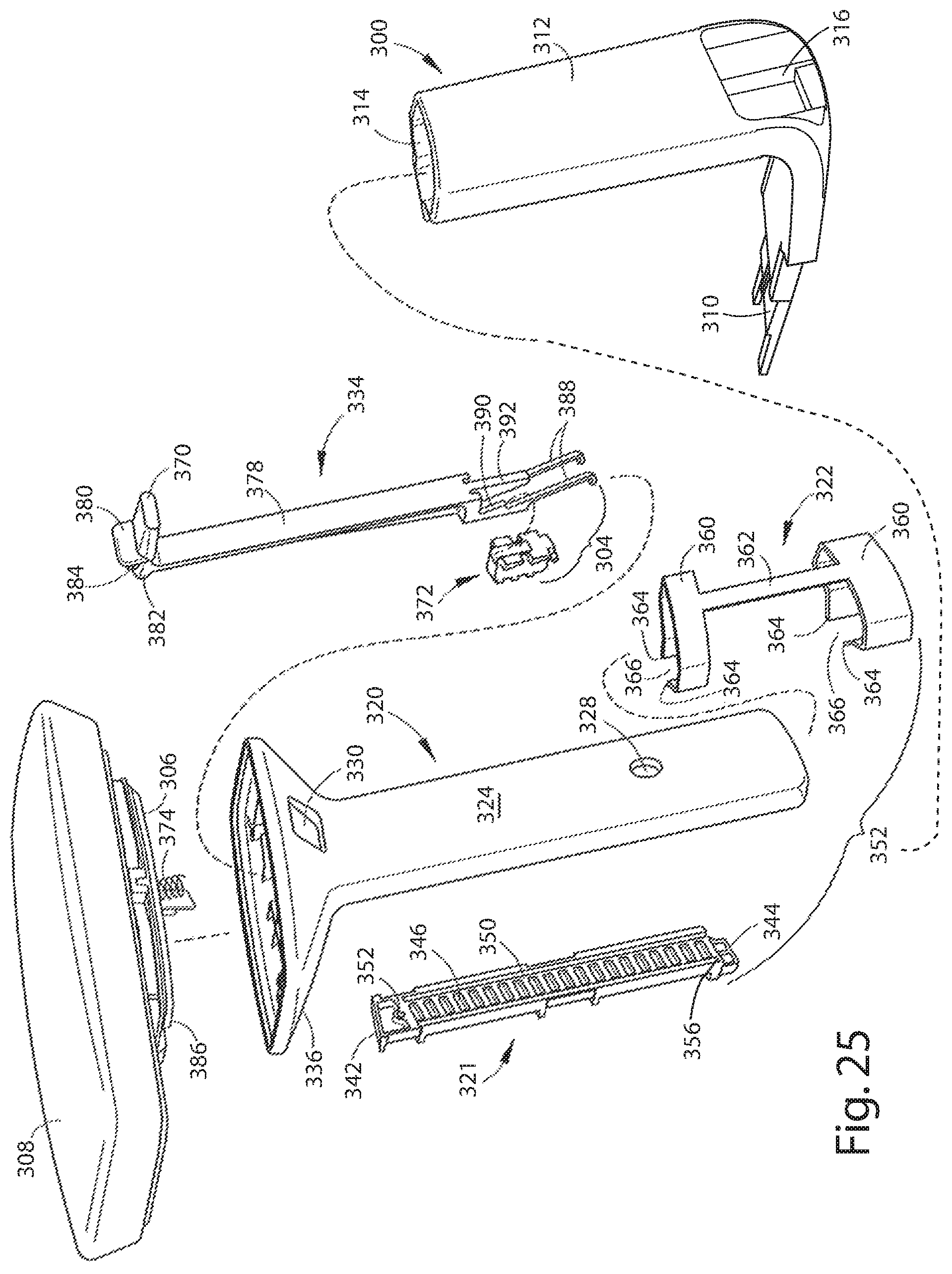
FIG. 25 is an exploded view of the armrest;
FIG. 26 is an exploded side perspective view of an armrest;
FIG. 27 is a perspective view of a post showing a first vertical surface of the post including detents;
FIG. 28 is a front perspective view of a locking member;
FIG. 29 is a rear perspective view of the locking member of FIG. 28;
FIG. 30 is a fragmentary view of the post and locking member;
FIG. 31 is a fragmentary view of the post, locking member and actuator rod;
FIG. 32 is a cross-sectional view of the armrest in a locked position;
FIG. 32A is an enlarged fragmentary view of the circled area XXXIIA in FIG. 32;
FIG. 33 is a cross-sectional view of the armrest in FIG. 32 shown in an unlocked position;
FIG. 33A is an enlarged fragmentary view of the circled area XXXIIIA in FIG. 33;
FIG. 34 is a cross-sectional view of the armrest in FIG. 32 shown in an unlocked position;
FIG. 34A is an enlarged schematic view of the circled area XXXIVA in FIG. 34;
FIG. 35 is a cross-sectional view of the armrest in FIG. 32 shown in a locked position;
FIG. 35A is an enlarged schematic view of the circled area XXXVA in FIG. 35;
FIG. 36 is a perspective view of a chair assembly;
FIG. 37 is a front view of the chair assembly as shown in FIG. 36;
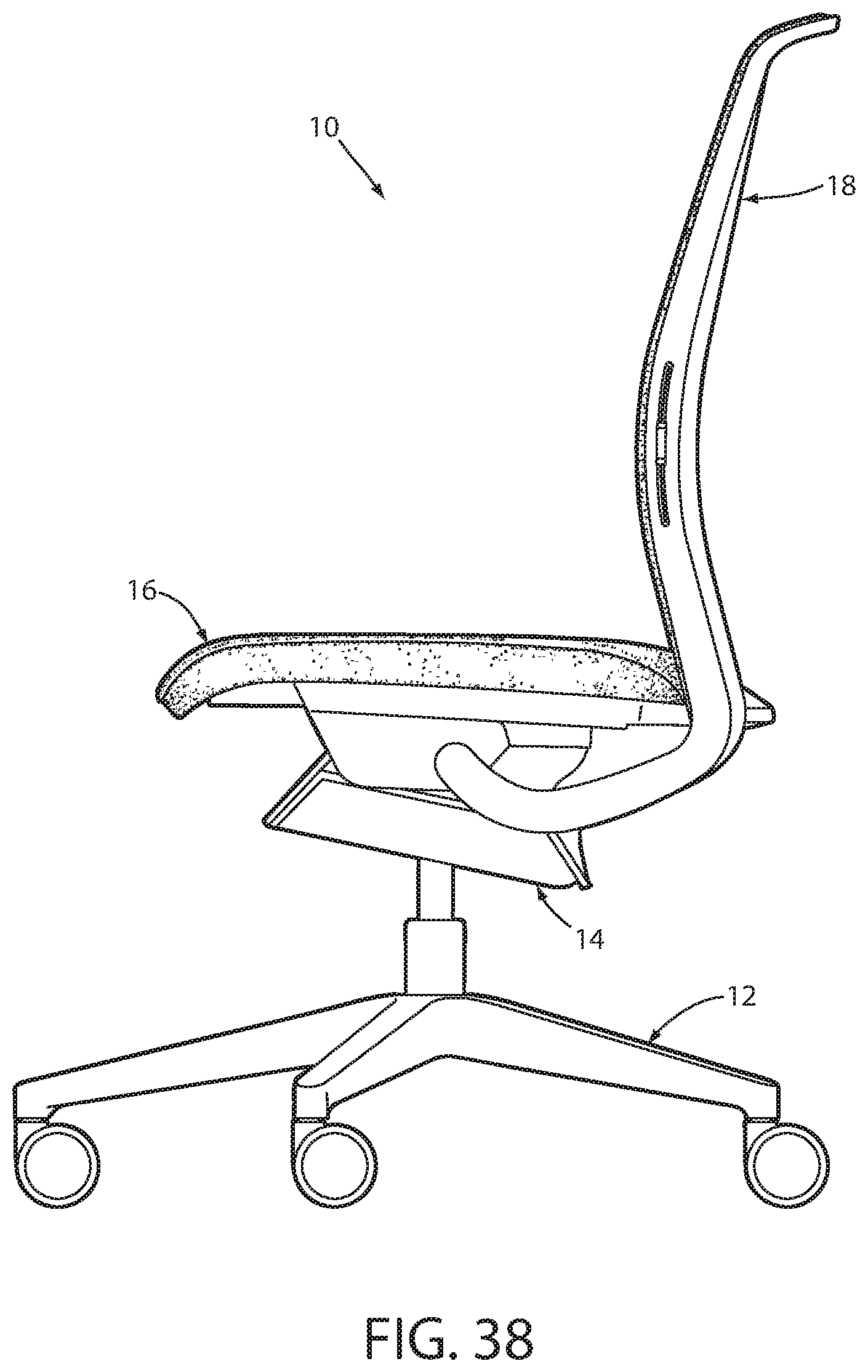
FIG. 38 is first side view of the chair assembly as shown in FIG. 36;
FIG. 39 is a second side view of the chair assembly as shown in FIG. 36;
FIG. 40 is a rear view of the chair assembly as shown in FIG. 36;
FIG. 41 is a top view of the chair assembly as shown in FIG. 36;
FIG. 42 is a bottom view of the chair assembly as shown in FIG. 36;
FIG. 43 is a perspective view of an upper corner of a back assembly of a chair;
FIG. 44 is a front view of the upper corner of the back assembly shown in FIG. 43;
FIG. 45 is a side view of the upper corner of the back assembly shown in FIG. 43;
FIG. 46 is a rear view of the upper corner of the back assembly shown in FIG. 43;
FIG. 47 is a top view of the upper corner of the back assembly shown in FIG. 43;
FIG. 48 is a perspective view of a handle apparatus of a lumbar assembly of a chair assembly;
FIG. 49 is a side view of the handle apparatus as shown in FIG. 48;
FIG. 50 is a rear view of the handle apparatus as shown in FIG. 48;
FIG. 51 is a top view of the handle apparatus as shown in FIG. 48; and
FIG. 52 is a bottom view of the handle apparatus.
DETAILED DESCRIPTION OF THE PREFERRED EMBODIMENTS
For purposes of description herein, the terms "upper," "lower," "right," "left," "rear," "front," "vertical," "horizontal," and derivatives thereof shall relate to the invention as oriented in FIG. 1. However, it is to be understood that the invention may assume various alternative orientations, except where expressly specified to the contrary. It is also to be understood that the specific devices and processes illustrated in the attached drawings, and described in the following specification are simply exemplary embodiments of the inventive concepts defined in the appended claims. Hence, specific dimensions and other characteristics relating to the embodiments disclosed herein are not to be considered as limiting, unless the claims expressly state otherwise. Various elements of the embodiments disclosed herein may be described as being operably coupled to one another, which includes elements either directly or indirectly coupled to one another.
The reference numeral 10 (FIGS. 1 and 2) generally designates a chair assembly embodying the present invention. In the illustrated example, the chair assembly 10 includes a castered base assembly 12 abutting and supported by a floor surface 13, a control or support assembly 14 supported by the castered base assembly 12, a seat assembly 16 and a back assembly 18 each operably coupled with the control assembly 14, and a pair of arm assemblies 20. The seat assembly 16 (FIG. 3) and the back assembly 18 are operably coupled with the control assembly 14 such that the back assembly 18 is movable between a fully upright position A and a fully reclined position B, and further such that the seat assembly 16 is movable between a fully upright position C and a fully reclined position D corresponding to the fully upright position A and the fully reclined position B of the back assembly 18, respectively.
The base assembly 12 includes a plurality of pedestal arms 21 radially extending and spaced about a hollow central column 22 that houses a pneumatic cylinder therein for adjusting the overall vertical height of the control assembly 14, the seat assembly 16 and the back assembly 18 above the floor surface 13. Each pedestal arm 21 is supported above the floor surface 13 by an associated caster assembly 24. Although the base assembly 12 is illustrated as including a multiple-arm pedestal assembly, it is noted that other suitable supporting structures may be utilized, including but not limited to fixed columns, multiple leg arrangements, vehicle seat support assemblies, and the like.
The seat assembly 16 (FIGS. 4 and 5) includes a seat shell member 30 having a forward edge 32, a rearward edge 34, and a pair of side edges 36 extending between the forward edge 32 and the rearward edge 34, wherein the forward edge 32, the rearward edge 34 and the side edges 36 cooperate to form an outer periphery of the seat shell member 30. In the illustrated example, the seat shell member 30 comprises an integrally molded plastic unitary member, however, other suitable structures and materials may also be utilized. The seat shell member 30 further includes a downwardly opening channel 38 having a C-shaped cross-sectional configuration and extending about the periphery of the seat shell 30. A plurality of couplers 40 (FIG. 6) are integral with the seat shell 30, and are located within and spaced along the channel 38. Each coupler 40 includes a pair of ribs 42 each having a downwardly angled abutment surface 44. Each coupler 40 further includes a flexibly resilient engagement tooth 46 interspaced with the pair of ribs 42. The seat assembly 16 further includes a foam cushion member 48 having a forward edge 50, a rearward edge 52, and a pair of side edges 54 extending therebetween, wherein at least the forward edge 50, and the side edges 54 of the cushion member 48 cooperate to form a downwardly opening pocket 56 that receives a portion of the seat shell 30 therein. The seat assembly 16 further includes an upholstery cover assembly 58. In the illustrated example, the cover assembly 58 includes a cover 60 comprising a stretchable fabric and including an upper portion 62 and a plurality of side portions 64 extending about the upper portion 62 and which cooperate to define an interior space 66 that receives an assembly of the seat shell 30 and the cushion member 48 therein. The cover assembly 58 further includes a drawstring tunnel 68 extending about a peripheral edge of the side portions 64 and receiving a drawstring 70 therein, wherein the drawstring 70 includes a pair of free ends 72 extending from the drawstring tunnel 68.
In assembly, the seat shell 30 (FIG. 7A) and the cushion member 48 are located within the interior space 66 of the upholstery cover assembly 58 such that the drawstring tunnel 68 (FIG. 8A) and the drawstring 70 are located within the channel 38 and such that the drawstring tunnel 68 and drawstring 70 impinge upon the ribs 42 and are engaged by the teeth 46, thereby securing the drawstring tunnel 68 and the drawstring 70 within the channel 38.
As best illustrated in FIG. 8A, the free ends 72 of the drawstring 70 are secured to the seat shell 30 by a fastener or clip member 80 (FIG. 9A). In the illustrated example, the clip member 80 is a spring clip having U-shaped spring body 82 having engagement teeth 84 spaced along the length thereof, and a pair of flanges 86 extending outwardly from the sides of the U-shaped spring body 82. In assembly, the clip 80 (FIGS. 8B and 8C) is vertically aligned with a respective free end 72 of the drawstring 70, and is then inserted into a portion of the channel 38 of the seat shell 30, thereby holding the free end 72 of the drawstring 70 within the channel 38. Alternatively, the clip member 80 (FIG. 8A) can engage a separate aperture 88 within the seat shell member 30, thereby securing at least a portion of the free end 72 of the drawstring 70 within the aperture 88. Alternatively, multiple clip members 80 (FIG. 8B) may be used to secure one of the free ends 72 of the drawstring 70 within the channel 38. As best illustrated in FIG. 8C, another alternative embodiment includes the securement of two free ends 72 of a drawstring 70 by a single clip 80.
The reference numeral 16a (FIG. 7B) generally designates another embodiment of the seat assembly. Since the seat assembly 16a is similar to the previously described seat assembly 16, similar parts appearing in FIG. 7B and FIG. 7A, respectively, are represented by the same, corresponding reference numeral, except for the suffix "a" in the numerals of the latter. In the illustrated example, the seat assembly 16a includes the seat shell 30a and the cushion member 48a located within the interior space 66a of the upholstery cover assembly 58a such that a stile or extrusion 73a is located within the channel 38a, thereby securing the cover assembly 58a to the seat shell 30a. As illustrated, the elastically deformable extrusion 73a has a J-shaped cross-sectional configuration, including a hook portion 75a that snappingly engages the teeth 46 upon insertion of the extrusion 73a into the channel 38a. The cover 60a is preferably sewn to the extrusion 73a, however, other suitable connection methods may also be utilized.
The back assembly 18 (FIGS. 10 and 11) includes a substantially rigid peripheral frame 90 that includes a laterally extending top portion 92, a laterally extending bottom portion 94, and a pair of vertically extending side portions 96, wherein the top portion 92, the bottom portion 94 and the side portions 96 cooperate to form a central opening 98. The back assembly 18 further includes a lumbar support assembly 100 adapted to support a lumbar area of a seated user and received within slots 102 extending vertically along each of the side portions 96 of the peripheral frame 90. A pair of side extensions 104 extend vertically along and are received within pockets 106 of the side portions 96 and are secured thereto by a plurality of mechanical fasteners 107.
The back assembly 18 further includes a substantially flexible back shell 108 including a top portion 110, a bottom portion 112, and a pair of side portions 114 that align with the top portion 92, the bottom portion 94 and the side portions 96 of the peripheral frame 90, respectively and as described below. The back shell 108 further includes a plurality of vertically spaced slats 116 extending between the side portions 114 and defining a plurality of slots 118 therebetween. In assembly, the back shell 108 (FIG. 12) is attached to the peripheral frame 90 in such a manner so as to define vertically spaced zones or regions of differing flexibility for the back shell 108. Specifically, the back shell 108 is attached to the peripheral frame 90 such that a top region 120 and a bottom region 122 of the back shell 108 are fixed with respect to the peripheral frame 90, a third region 124 of the back shell 108 is constrained with respect to the peripheral frame 90 in a forward direction, and a fourth region 126 of the back shell 108 is free to separate from the peripheral frame 90 in a forward direction, wherein the flexed state of the back shell 108 is shown in dashed line. More specifically, and as best illustrated in FIGS. 13A and 13B, the top portion 92 of the peripheral frame 90 includes a plurality of upwardly-extending hooks 130 integral with and spaced across the top portion 92, while the top portion 110 of the back shell 108 includes a plurality of downwardly-extending flexibly resilient loops 132 integral with the top portion 110, wherein the hooks 130 engage the loops 132, thereby flexing the loops 132 in a direction 133 during engagement and fixedly securing the top portion 110 of the back shell 108 to the top portion 92 of the peripheral frame 90. As best illustrated in FIG. 12, the back shell 108 includes a pair of integral tab members 134 located at the intersection of the side portions 114 and the bottom portion 112, wherein the tab members 134 are secured to peripheral frame 90 by mechanical fasteners such as bolts 136, thereby fixedly securing the bottom portion 112 of the back shell 108 to the bottom portion 94 of the peripheral frame 90. As best illustrated in FIG. 14, the third region 124 of the back shell 108 includes rearwardly and downwardly extending hooks 140 located along the length and integral with the side portions 114 of the back shell 108. Each hook 140 is received within a pocket 142 formed between the side extensions 104 and the side portions 96, such that the back shell 108 is pivotable about a pair of axis 144 extending vertically through the corresponding hooks 140. The pockets 142 located within the third region 124 are also sized so as to allow lateral displacement of the hooks 140 within the pockets 142 in a direction 146 so as to allow the side portions 114 of the back shell 108 to flex inwardly with respect to the side portions 96 of the peripheral frame 90 thereby in turn, allowing increased flexibility and compliance of the back shell 108 in a rearward direction 148 with respect to the peripheral frame 90. The side portions 114 of the back shell 108 located within the fourth region 126 are not secured to the side portions 96 of the peripheral frame 90, thereby allowing maximum compliance and flexibility of the back shell 108 with respect to the peripheral frame 90 in both the lateral direction 146 and in the rearward direction 148. As a result, the first and second regions 120, 122 of the back shell 108 are constrained from movement with respect to the peripheral frame 90, the third region 124 allows limited compliance of the back shell 108 with respect to the frame 90, while the fourth region 126 allows for maximum flexure of the back shell 108 with respect to the frame 90.
The reference numeral 18b (FIG. 11B) generally designates another embodiment of the back assembly. Since the back assembly 18b is similar to the previously described back assembly 18, similar parts appearing in FIGS. 11B and 11A, respectively, are represented by the same, corresponding reference numeral, except for the suffix "b" in the numerals of the latter. In the illustrated example, the upholstery cover assembly 150b includes a drawstring 160b and a plurality of stiles or extrusions 151b attached to and extending along the side portions 154b of the cover assembly 150b. As best illustrated in FIG. 11C, each extrusion 151b has a J-shaped cross-sectional configuration that is secured to the cover assembly 150b via a stitch 153b, and that includes a hook portion 155b that engages the teeth 168b of the couplers 162b of the back shell 108b. The drawstring 160b is located within a drawstring tunnel 158b that is secured to the associated side portion 154b via a stitch 157b and is drawn about the back shell 108b subsequent to the extrusions 151b being secured to the back shell 108b. The free ends 163b of the drawstring 160b are secured to one another via a ferrule 165b. In the illustrated example, the drawstring 160b is relatively incompressible and is comprised of a single strand polypropylene material, although materials such as nylon as well as multistrand constructions may also be utilized.
The reference numeral 18c (FIG. 19) generally designates another embodiment of the back assembly. Since the back assembly 18c is similar to the previously described back assembly 18, similar parts appearing in FIG. 10 and FIG. 19 are identified by the same, corresponding reference numerals except for the suffix "c" in the numerals of the latter. In the illustrated example, the back assembly 18c includes a rigid back frame 90c, a top cover member 500 covering an upper portion of the back shell 108c that includes an upper portion 502 and a separate lower portion 504. A plate member 506 (FIGS. 20 and 21) extends laterally across the upper portion 92c of the back frame 90c and is positioned between the upper portion 92c of the back frame 90c and the back shell 108c, as described below. As best illustrated in FIGS. 20 and 21, the plate member 506 includes an elongated body portion 510, a pair of outwardly located, forwardly-extending alignment tabs 512, a pair of forwardly-extending connection tabs 514, a centrally positioned, forwardly-extending alignment tab 516, and a plurality of rearwardly-extending engagement tabs 518. Each of the alignment tabs 512, the connection tabs 514 and the alignment tabs 516 are received within corresponding apertures 520 (FIG. 21) formed between the upper portion 502 and the lower portion 504 of the back shell 108c.
As best illustrated in FIG. 21, the upholstery assembly 150c includes a fabric or mesh fabric 522, and a thin foam layer 522. The plate member 506 (FIG. 21) is positioned such that an edge of the fabric 522 is trapped between the plate member 506 and the lower portion 504 of the back shell 108c, and the plate member 506 is then heat staked to the lower portion 504 of the back shell 108c and separately to the upper portion 502 of the back shell 108c, thereby structurally coupling the upper portion 502 to the lower portion 504 through the plate member 506. It is noted that the structurally reinforcing plate member 506 is coupled to the back frame 90c subsequent to the fabric 522 being secured about the back shell 108c. The back shell 108c is secured to the back frame 90c by engaging each of the engagement tabs 518 into a corresponding groove 528 located within the upper portion 92c of the back frame 90c, such that the plate member 506 properly aligns the back shell 108c with the back frame 90c assuring proper fit and finish for the aesthetics of the chair.
The back assembly 18 further includes a back upholstery cover assembly 150 having a front portion 152 and a plurality of side portions 154 that cooperate to form an interior space 156 that receives the back shell 108 therein. The upholstery assembly 150 is comprised of a stretchable fabric material and includes a drawstring tunnel 158 that extends about an inner periphery of the side portions 154 and houses a drawstring 160 therein. As best illustrated in FIG. 13A, the upholstery assembly 150 receives a portion of the back shell 108. Alternatively, the upholstery assembly 150' (FIG. 13C) extends about a portion of the back shell 108', a foam cushion member 155', and an inner fabric layer 157' which separates the cushion member 155' from the back shell 108'.
As best illustrated in FIGS. 13A and 15, the back shell 108 includes a plurality of couplers 162 spaced about the periphery of the back shell 108. In the illustrated example, each coupler 162 includes a pair of outwardly-extending fingers 164 that are formed so as to define an opening facing an outer peripheral edge 166 of the back shell 108. A plurality of flexibly resilient teeth 168 are interdigitated with the fingers 164 of the coupler 162. In assembly, the upholstery assembly 150 wraps about the edges of the back shell 108 such that the drawstring tunnel 158 and the drawstring 160 are received within the couplers 162 and engaged by the teeth 168, thereby retaining the drawstring tunnel 158 and the drawstring 160 within the associated couplers 162.
The lumbar assembly 100 (FIGS. 10, 11A and 16) includes a body shell 200 housing a laterally extending decorative plate 202, a pair of lateral extending leaf springs 203, a pair of sliding connection assemblies 204, and a pair of adjustment handles 205 configured for grasping by a user to move the lumbar assembly 100 between a lowered position E (FIG. 2) and a raised position F. The molded body shell 200 includes a front portion 206 and a back portion 208 arcuately shaped and vibrationally welded to one another in a back-to-back relationship to form a pocket 210 (FIG. 17) which receives the decorative plate 202 therein. Alternatively, other methods of coupling the front and back portions 206, 208 may be utilized, including mechanical fasteners such as screws, snaps, ultra sonic welding, adhesives, and the like. The leaf springs 203 extend along the length of the body shell 200 and are located within respective pockets 212 juxtaposed from one another across the pocket 210. The leaf springs 203 are adapted to provide a forward biasing force against a rearward force exerted by a lumbar area of a seated user's back. The sliding connection assemblies 204 are attached to the ends of the lumbar assembly 100 and are slidably received with an elongated relief 218 (FIG. 18A) formed between the respective side portion 96 of the peripheral frame 90 and the side extensions 104, such that the lumbar assembly 100 is vertically movable between the lowered and raised positions E, F. Specifically, the body shell 200 includes a pair of vertically extending ribs 219 that guide along the respective side extensions 104, thereby centering the lumbar assembly 100 with respect to the frame 90. It is noted that the relative width of peripheral frame 90 or lateral distance between the slots 102 changes along the path the lumbar assembly 100 travels when vertically adjusted, thereby requiring a sliding connection between the sliding connection assemblies 204 and the body shell 200. As best illustrated in FIG. 18B, each end of the front portion 206 of the body shell 200 includes a pair of barrel-headed tabs 220 slidably received within a pair of corresponding slots 222 which allows for sliding adjustment between the connection assemblies 204 and the body shell 200 while preventing the body shell 200 from disengaging the connection assemblies 204. In assembly, and as best illustrated in FIGS. 12A and 18C, each handle 205 includes a blade portion 207 that is slidably received within a corresponding pocket 209 of the connection assembly 204 and is held therein by a flexibly resilient tab 211 that engages an aperture 213 of the blade portion 207, thereby slidably securing the lumbar assembly 100 within the slots 102. Each connection assembly 204 further includes a flexibly resilient bar 217 with a pawl member 219 that selectively engages a plurality of detents 221 (FIG. 10) vertically spaced along the side portion 102 of the frame 90, thereby holding the lumbar assembly 100 in a selected vertical position with respect to the frame 90.
As best illustrated in FIG. 3, the seat assembly 16 is movable between a retracted position G and an extended position H, thereby providing depth adjustment for the chair assembly 10. The seat assembly 16 (FIGS. 4 and 5) is slidably supported on the control assembly 14. The control assembly 14 (FIG. 22) includes support plates 251, 252 disposed on opposite sides of the overall control assembly 14. The control assembly 14 further includes an actuator bar 253 which is generally U-shaped and includes a handle portion 254 disposed under a front portion of the seat assembly 16 and adapted to be grasped by a user, and a pair of arm portions 255 extending rearwardly from the handle portion 254. Upon actuating the actuator bar 253, the handle portion 254 is lifted upward in a direction 256, wherein the actuator bar 253 pivots in the seat shell 30 at pivot point 257 which causes the distal ends 258 of the arm portions 255 to move downward in a direction 259 to engage corresponding rockers 260 which are pivotably connected to the seat shell 30 about pivot axis 261. The actuation of the actuator bar 253 moves the rockers 260 from an engaged position to a disengaged position, thereby allowing movement of the seat assembly 16 between the retracted and extended positions G, H. Specifically, the rockers 260 selectively engage a plurality of reliefs 262 of corresponding racks 263, thereby allowing the seat assembly 16 to be selectively locked at positions between the retracted and extended positions.
As shown in FIGS. 7A and 23, the bottom surface 265 of the seat shell 30 includes a downwardly opening integral linear guide bearing channel 266 extending front-to-back of the seat shell 30. As best illustrated in FIG. 20, the support plate 252 includes a pair of upwardly-extending guide portions 270 that slidably track within the linear bearing 266 of the seat shell 30, thereby linearly guiding the seat shell 30 with respect to the support plate 252 and the overall control assembly 14. The support plate 252 includes an L-shaped guide portion 290 (FIG. 22) housed in a bearing member 291, which is received within a corresponding inwardly-opening slot 292, such that the guide portion 290 of the support plate 252 guides within the slot 292 as the seat assembly is moved between the retracted and extended positions G, H.
Alternatively, a removable stop member 293 may be secured to an underside of the seat shell 30 at a position such that the stop member abuts a portion 295 of the support plate 251, thereby limiting the amount of travel of the seat assembly 16 from the extended position to the retracted position and preventing the seat assembly 16 from moving to the rearward-most position. In the illustrated example, the stop member 293 is secured to the seat shell 30 via a screw 297, thereby requiring the use of a tool for installation and removal.
Each armrest assembly 20 (FIGS. 3, 24 and 25) is vertically adjustable between a raised position I and a lowered position J and includes a tubular support 300 constructed for attachment to a chair 10, an armrest assembly 302 telescopingly positioned in the tubular support, and a height adjustment mechanism 304 slidably received in the armrest assembly. A plate 306 is attached to the top of the armrest assembly 302 and an arm cap 308 is attached to the plate 306. In an alternative embodiment, a pivot/slide member 309 may be attached to the plate and the arm cap 308 attached to the pivot/slide member. The pivot/slide member is similar to that disclosed in co-assigned U.S. Pat. No. 5,971,484, filed Dec. 3, 1997, entitled "ADJUSTABLE ARMREST FOR CHAIRS," the contents of which are incorporated herein by reference for its teachings.
Referring to FIGS. 25 and 26, the tubular support 300 includes an L-shaped structural member having a horizontal first arm section 310 adapted for connection to the fixed side support structures, and a vertically extending second arm section 312. The second arm section 312 includes an upper opening 314 for telescopingly receiving the armrest assembly 302, a lower opening 316, and a groove 318 including a fastening aperture 319, along one vertical side. When the armrest assembly 302 is inserted into the second arm section 312, the lower portion of a sleeve 320 extends through the lower opening 316 and is visible. As the armrest assembly is vertically adjusted upward, the sleeve becomes less visible. The groove 318 and the lower opening 316 are on opposite sides of the second arm section 312.
The armrest assembly 302 is telescopingly received in the tubular support 300 and includes a sleeve 320, a post 321, and may also include a bearing 322. The sleeve 320 includes a first side 324 and a second side 326. The first side 324 may include an aperture 328 near the lower end of the first side. Near the top of the first side 324 is an opening 330 which is adapted to receive an operative member 370 of an actuator rod 334. The sleeve 320 flares out at the top to provide an armrest support 336. The second side 326 of the sleeve 320 includes a rectangular aperture 338 at the lower end of the second side. On either side of the aperture 338 is a vertical rib 340 and a vertical rib 341, wherein the vertical rib 341 is significantly longer than the vertical rib 340, thereby increasing the overall effective length of the ribs 340, 341, and preferably provides a length l to width w ratio of at least 3:1, and is preferably at least 10:1, thereby reducing the fore-to-aft shifting of the armrest assembly 302 within the tubular support 300. Referring to FIGS. 25 and 26, the post 321 is rectangular with a lip 342 on its top end and a tab 344 on the bottom end. The post also includes a first vertical surface 346 and a second vertical surface 348. The first vertical surface 346 includes a series of positional detents 350 and a fastening aperture 352 (FIG. 27). The fastening aperture 352 extends completely through the post 321 to the second vertical surface 348. On either side of the positional detents 350 are vertical grooves 354, wherein one of the grooves 354 extends through the bottom of the post 321, and wherein the grooves 354 mateably receive the vertical ribs 340, 341 on the sleeve 320 to prevent complete removal of the armrest assembly 302 from the tubular support 300. Specifically, in the illustrated example, one of the channels in 354 includes an endwall 356 that is abutted by a corresponding rib 340, thereby preventing removal of the arm rest assembly 302 from the tubular support 300. The remaining groove 354 extends through the end of the post 321 to allow passage of the secondary vertical rib 341. The second vertical surface 348 includes ridges 358. The bearing 322 provides a bearing surface and includes two collars 360 which are connected to a vertical strip 362 at their midpoints. Although FIGS. 25 and 26 show the collars 360 as angled relative to each other, in an alternative embodiment, the collars are parallel relative to each other. The ends 364 of the collars 360 flare outwardly to define a space 366.
The post 321 is mateably received in the groove 318 of the second arm section 312, with the second vertical surface 348 abutting the second arm section 312. A fastening means is inserted through fastening aperture 319 and into fastening aperture 352 to secure the post 321 in the groove 318. Alternatively, it is contemplated that the post 321 is not a separate piece fastened in the groove 318, but rather molded into the second arm section 312. When the sleeve 320 is inserted into the second arm section 312, the first vertical surface 346 of the post 321 abuts the second side 326 of the sleeve. Also, the detents 350 on the first vertical surface 346 of the post 321 cover the aperture 338 on the second side 326 of the sleeve 320. The vertical ribs 340, 341 on the second side 326 of the sleeve 320 mate with the vertical grooves 354 of the post 321 so that the positional detents 350 remain positioned over the aperture 338 when the sleeve is adjusted vertically. The bearing 322 is positioned on the sleeve 320 with the vertical strip 362 abutting the first side 324 of the sleeve 320, allowing the collars 360 to wrap around the sleeve 320. The post 321 fits between the collar ends 364 in the space 366. The bearing 322 is stationary within the second arm section 312 and functions to limit horizontal movement of the sleeve within the tubular support.
The height adjustable mechanism 304 comprises the actuator rod 368 that includes the operative member 370, a locking member 372, and a spring 374. In the illustrated example, the operative member 370 is located at the top of the actuator rod 368 and is generally perpendicular to an elongated portion 378 of the actuator rod 368. As shown, the operative member 370 is a lever, however, it is contemplated that a button or tab could be used. Attached to the operative member 370 is a flange 380. On the other side of the flange 380 is a ledge 382 having a protrusion 384. When the height adjustable mechanism 304 is slidably engaged with the armrest assembly 302, the actuator rod 368 is positioned inside the sleeve 320 with the operative member 370 positioned through aperture 330. One end of the spring 374 is placed over the protrusion 384, with the opposite end of the spring 374 placed over a protrusion 386 on the underside of the plate 306. Located at the bottom of the actuator rod 334 (FIG. 33) are two angled ramps 388 which resemble hooks. The angled ramps 388 prevent the locking member 372 from falling to the bottom of the sleeve 320. Above each angled ramp 388 is at least one angled surface, and preferably a pair of angled surfaces 390. Between the pair of angled surfaces 390 is an inclined wedge 392.
As best seen in FIGS. 28-30, the locking member 372 includes teeth 394 that selectively mateably engage the detents 390 on the post 321. The locking member 372 also includes an inclined surface 396 that mates with the inclined wedge 392. The locking member 372 also includes at least one pair, and preferably two pairs of lateral followers 398 which releasably mateably engage the two pairs of angled surfaces 390.
The height adjustable mechanism 304 is slidably engaged within the sleeve 320. When in a locked position, the locking member 372 of the height adjustable mechanism 304 is positioned such that the teeth 394 of the locking member extend through aperture 338 of the sleeve 320 and selectively mate with the detents 350 of the post 321. The actuator rod 368 is positioned over the locking member 372 with the inclined wedge 392 mateably engaged with the inclined surface 396 and the angled surfaces 390 releasably mateably engaged with the lateral followers 398 (FIGS. 31, 32 and 32A).
To vertically adjust the height of the armrest, the operative member 370 is lifted upward, which in turn, compresses the spring 374. When the spring compresses, the angled surfaces 390 of the actuator rod 368 lift upward and push on the lateral followers 398, which causes the teeth 394 to withdraw into the sleeve 320, thereby removing the locking member 372 from locking engagement with the detents 350 (FIGS. 33 and 33A). Once the locking member 372 is disengaged from the detents 350, the armrest can be vertically adjusted upward or downward to a desired height.
To reengage the locking member 372 and relock the armrest in a selected position, the operative member 370 is released, thereby decompressing the spring 374 at the top of the actuator rod 368. Decompression of the spring causes the inclined wedge 392 to slide into mateable engagement with the inclined surface 396. (FIGS. 34, 34A, 35 and 35A). As the inclined wedge 392 and inclined surface 396 are mateably engaged, the teeth 394 of the locking member again extend through the aperture 338 and selectively mate with the detents 350 of the post 321.
An embodiment of a chair assembly is illustrated in a variety of views, including a perspective view (FIG. 36), a front elevational view (FIG. 37), a first side elevational view (FIG. 38), a second side elevational view (FIG. 39), a rear elevational view (FIG. 40), a top plan view (FIG. 41), and a bottom plan view (FIG. 42). A portion of an embodiment of a back assembly is illustrated in a variety of views, including a perspective view (FIG. 43), a front elevational view (FIG. 44), a side elevational view (FIG. 45), a rear elevational view (FIG. 46), and a top plan view (FIG. 47). An embodiment of an adjustment handle is illustrated in a variety of views, including a perspective view (FIG. 48), a side elevational view (FIG. 49), a front elevational view (FIG. 50), a top view (FIG. 51), and a bottom view (FIG. 52).
In the foregoing description, it will be readily appreciated by those skilled in the art that alternative combinations of the various components and elements of the invention and modifications to the invention may be made without departing from the concepts as disclosed. Such modifications are to be considered as included in the following claims, unless these claims by their language expressly state otherwise.
* * * * *
D00000
D00001
D00002
D00003
D00004
D00005
D00006
D00007
D00008
D00009
D00010
D00011
D00012

D00013

D00014

D00015

D00016

D00017

D00018

D00019

D00020

D00021
D00022

D00023

D00024

D00025

D00026

D00027

D00028
D00029

D00030

D00031

D00032

D00033

XML
uspto.report is an independent third-party trademark research tool that is not affiliated, endorsed, or sponsored by the United States Patent and Trademark Office (USPTO) or any other governmental organization. The information provided by uspto.report is based on publicly available data at the time of writing and is intended for informational purposes only.
While we strive to provide accurate and up-to-date information, we do not guarantee the accuracy, completeness, reliability, or suitability of the information displayed on this site. The use of this site is at your own risk. Any reliance you place on such information is therefore strictly at your own risk.
All official trademark data, including owner information, should be verified by visiting the official USPTO website at www.uspto.gov. This site is not intended to replace professional legal advice and should not be used as a substitute for consulting with a legal professional who is knowledgeable about trademark law.