Towing systems and methods using magnetic field sensing
Reed , et al.
U.S. patent number 10,670,479 [Application Number 16/136,837] was granted by the patent office on 2020-06-02 for towing systems and methods using magnetic field sensing. This patent grant is currently assigned to Methode Electronics, Inc.. The grantee listed for this patent is Methode Electronics Inc.. Invention is credited to Julius Beck, Florian Burghardt, Johannes Gie ibl, Chad Reed.


View All Diagrams
| United States Patent | 10,670,479 |
| Reed , et al. | June 2, 2020 |
Towing systems and methods using magnetic field sensing
Abstract
A magneto-elastically-based active force sensor, used with a tow coupling between a towed and a towing vehicle, which outputs a signal useful for determining forces acting on the coupling. The outputted force information may be provided by processor-enabled embedded software algorithms that take inputs from the force sensor and other sensors, may be used by one or more vehicle systems during operating of the vehicle, such as engine, braking, stability, safety, and informational systems. The force sensor includes directionally-sensitive magnetic field sensing elements inside the sensor, and shielding may be used around the sensors to reduce the influence of external magnetic fields on the sensing elements. The force sensor may be used with different tow coupling devices installed on different types of automobile cars and trucks.
| Inventors: | Reed; Chad (Southfield, MI), Beck; Julius (Haar, DE), Burghardt; Florian (Haar, DE), Gie ibl; Johannes (Haar, DE) | ||||||||||
|---|---|---|---|---|---|---|---|---|---|---|---|
| Applicant: |
|
||||||||||
| Assignee: | Methode Electronics, Inc.
(Chicago, IL) |
||||||||||
| Family ID: | 67684443 | ||||||||||
| Appl. No.: | 16/136,837 | ||||||||||
| Filed: | September 20, 2018 |
Prior Publication Data
| Document Identifier | Publication Date | |
|---|---|---|
| US 20190265112 A1 | Aug 29, 2019 | |
Related U.S. Patent Documents
| Application Number | Filing Date | Patent Number | Issue Date | ||
|---|---|---|---|---|---|
| 62635848 | Feb 27, 2018 | ||||
| 62635869 | Feb 27, 2018 | ||||
| 62635890 | Feb 27, 2018 | ||||
| 62677378 | May 29, 2018 | ||||
| Current U.S. Class: | 1/1 |
| Current CPC Class: | G01L 3/102 (20130101); G01L 1/125 (20130101); H01L 41/12 (20130101); G01L 5/136 (20130101) |
| Current International Class: | G01L 1/00 (20060101); H01L 41/12 (20060101); G01L 1/12 (20060101); G01L 3/10 (20060101) |
| Field of Search: | ;73/862.333 |
References Cited [Referenced By]
U.S. Patent Documents
| 2317718 | April 1943 | Barnes et al. |
| 3514997 | June 1970 | Gwathmey et al. |
| 3520184 | July 1970 | Tanner et al. |
| 3593263 | July 1971 | Olsen |
| 3737233 | June 1973 | Blau et al. |
| 3972231 | August 1976 | Richardson |
| 4105972 | August 1978 | Smith |
| 4384270 | May 1983 | Morita et al. |
| 4814743 | March 1989 | Hanaki |
| 4836019 | June 1989 | Hagen et al. |
| 5052232 | October 1991 | Garshelis |
| 5205169 | April 1993 | Hagen |
| 5223072 | June 1993 | Brockman |
| 5351564 | October 1994 | Watson et al. |
| 5616861 | April 1997 | Hagen |
| 5617025 | April 1997 | Taylor et al. |
| 5618999 | April 1997 | Schweitzer et al. |
| 5684254 | November 1997 | Nakazaki et al. |
| 5716071 | February 1998 | Stanley et al. |
| 5716302 | February 1998 | Andersson |
| 5727637 | March 1998 | Kono et al. |
| 5729194 | March 1998 | Spears et al. |
| 5731525 | March 1998 | Boe |
| 5738176 | April 1998 | Gingerich |
| 5739442 | April 1998 | Schweitzer et al. |
| 5741048 | April 1998 | Eccleston |
| 5741981 | April 1998 | Ling et al. |
| 5747683 | May 1998 | Gerum et al. |
| 5773722 | June 1998 | Helderman |
| 5777240 | July 1998 | Lefebvre et al. |
| 5780782 | July 1998 | O'Dea |
| 5780783 | July 1998 | Heider et al. |
| 5782542 | July 1998 | McGrath et al. |
| 5783751 | July 1998 | Maw et al. |
| 5785393 | July 1998 | McGrath et al. |
| 5791676 | August 1998 | Jones |
| 5800025 | September 1998 | McGrath et al. |
| 5806937 | September 1998 | Brunson |
| 5811738 | September 1998 | Boyovich et al. |
| 5821852 | October 1998 | Fairchild |
| 5822876 | October 1998 | Haas et al. |
| 5823637 | October 1998 | Blue |
| 5824771 | October 1998 | Rivier |
| 5831173 | November 1998 | Hanano |
| 5844146 | December 1998 | Murray et al. |
| 5848826 | December 1998 | Muller |
| 5851021 | December 1998 | Van Kley |
| 5853186 | December 1998 | Gentner et al. |
| 5861802 | January 1999 | Hungerink et al. |
| 5861814 | January 1999 | Clayton |
| 5863057 | January 1999 | Wessels |
| 5865593 | February 1999 | Cohn |
| 5876055 | March 1999 | Fontaine |
| 5876100 | March 1999 | Breckner et al. |
| 5877455 | March 1999 | Kyrtsos |
| 5880409 | March 1999 | Hartman |
| 5883312 | March 1999 | Hayashida |
| 5884238 | March 1999 | Noll et al. |
| 5910217 | June 1999 | Sargent |
| 5912616 | June 1999 | Valentino |
| 5915281 | June 1999 | Sparks |
| 5921641 | July 1999 | Lupges et al. |
| 5941560 | August 1999 | Wolfram |
| 5947225 | September 1999 | Kawakami et al. |
| 5947637 | September 1999 | Neuling |
| 5951035 | September 1999 | Phillips, Jr. et al. |
| 5957476 | September 1999 | Simpson |
| 5964476 | October 1999 | Maines |
| 5969270 | October 1999 | Doemes et al. |
| 5971432 | October 1999 | Gagnon et al. |
| 5980048 | November 1999 | Rannells, Jr. et al. |
| 5983729 | November 1999 | Taylor |
| 5985666 | November 1999 | Loiselle et al. |
| 5988000 | November 1999 | Adams |
| 5988666 | November 1999 | Flater |
| 6000709 | December 1999 | Gentner et al. |
| 6003614 | December 1999 | Crabb |
| 6012780 | January 2000 | Duvernay |
| 6012781 | January 2000 | Gerum |
| 6013880 | January 2000 | McFarlane et al. |
| 6014901 | January 2000 | Boe |
| 6025563 | February 2000 | Lesesky et al. |
| 6035943 | March 2000 | Gerein et al. |
| 6037550 | March 2000 | Bradley |
| 6039139 | March 2000 | Breed et al. |
| 6039410 | March 2000 | Robertson et al. |
| 6042196 | March 2000 | Nakamura et al. |
| 6044915 | April 2000 | Schlegel et al. |
| 6044916 | April 2000 | Hundeby |
| 6050649 | April 2000 | Hensley |
| 6053521 | April 2000 | Schertler |
| 6065353 | May 2000 | Hirabayashi et al. |
| 6068352 | May 2000 | Kulkarni et al. |
| 6079791 | June 2000 | Stumpe et al. |
| 6082203 | July 2000 | Koivisto et al. |
| 6082467 | July 2000 | Friesen |
| 6084183 | July 2000 | Nakazaki |
| 6095348 | August 2000 | Karashima |
| 6100794 | August 2000 | Hillier |
| 6100795 | August 2000 | Otterbacher et al. |
| 6105230 | August 2000 | Balestracci |
| 6112589 | September 2000 | Tressler et al. |
| 6116638 | September 2000 | Hosoda |
| 6118083 | September 2000 | Boyovich et al. |
| 6120052 | September 2000 | Capik et al. |
| 6126246 | October 2000 | Decker, Sr. et al. |
| 6127939 | October 2000 | Lesesky et al. |
| 6139118 | October 2000 | Hurst et al. |
| 6142959 | November 2000 | Sarvazyan et al. |
| 6144928 | November 2000 | Leimbach et al. |
| 6150617 | November 2000 | Hart et al. |
| 6152252 | November 2000 | Pettersson |
| 6152475 | November 2000 | Poole |
| 6157889 | December 2000 | Baker |
| 6161962 | December 2000 | French et al. |
| 6168181 | January 2001 | Gadd |
| 6176505 | January 2001 | Capik et al. |
| 6178650 | January 2001 | Thibodeaux |
| 6179319 | January 2001 | Malisch et al. |
| 6189644 | February 2001 | Taylor |
| 6196328 | March 2001 | McDaniel et al. |
| 6203045 | March 2001 | Kyrtsos et al. |
| 6203049 | March 2001 | Gibson |
| 6216072 | April 2001 | Boe et al. |
| 6218737 | April 2001 | Adamek et al. |
| 6222443 | April 2001 | Beeson et al. |
| 6222457 | April 2001 | Mills et al. |
| 6230817 | May 2001 | Haugen |
| 6234508 | May 2001 | Tuttle et al. |
| 6234511 | May 2001 | Gentner et al. |
| 6240339 | May 2001 | von Mayenburg et al. |
| 6240788 | June 2001 | Balestracci |
| 6242701 | June 2001 | Breed et al. |
| 6246316 | June 2001 | Andsager |
| 6250650 | June 2001 | Douglas |
| 6250863 | June 2001 | Kamentser et al. |
| 6252497 | June 2001 | Dupay et al. |
| 6259357 | July 2001 | Heider |
| 6262573 | July 2001 | Wojnarowski et al. |
| 6264337 | July 2001 | Rannells, Jr. et al. |
| 6268800 | July 2001 | Howard |
| 6273522 | August 2001 | Feetenby et al. |
| 6285278 | September 2001 | Schutt et al. |
| 6289749 | September 2001 | Sanders |
| 6299191 | October 2001 | Sargent |
| 6302424 | October 2001 | Gisinger et al. |
| 6308578 | October 2001 | DeRose |
| 6327903 | December 2001 | Hecker et al. |
| 6334746 | January 2002 | Nguyen et al. |
| 6349959 | February 2002 | Schlegel et al. |
| 6351697 | February 2002 | Baker |
| 6352277 | March 2002 | Timmings |
| 6354448 | March 2002 | Ramne |
| 6364432 | April 2002 | Mixon |
| 6371217 | April 2002 | Boden |
| 6375211 | April 2002 | MacKarvich |
| 6378620 | April 2002 | Luca et al. |
| 6378957 | April 2002 | Vagstedt |
| 6384716 | May 2002 | Eckelberry |
| 6394490 | May 2002 | Osmer et al. |
| 6401855 | June 2002 | Wolfe |
| 6407353 | June 2002 | Fritzinger et al. |
| 6408685 | June 2002 | Shin |
| 6416138 | July 2002 | Barnett |
| 6419037 | July 2002 | Kramer et al. |
| 6420798 | July 2002 | Adamek et al. |
| 6439545 | August 2002 | Hansen |
| 6445993 | September 2002 | Eccleston et al. |
| 6446998 | September 2002 | Koenig et al. |
| 6450523 | September 2002 | Masters et al. |
| 6452485 | September 2002 | Schutt et al. |
| 6456066 | September 2002 | Burd et al. |
| 6480104 | November 2002 | Wall et al. |
| 6490935 | December 2002 | Joki et al. |
| 6494476 | December 2002 | Masters et al. |
| 6494478 | December 2002 | MacKarvich |
| 6499814 | December 2002 | Mixon |
| 6516925 | February 2003 | Napier et al. |
| 6523911 | February 2003 | Rupp et al. |
| 6524221 | February 2003 | Nishimura |
| 6525276 | February 2003 | Vellidus et al. |
| 6531951 | March 2003 | Serban et al. |
| 6534728 | March 2003 | Spikings |
| 6547271 | April 2003 | Kleb et al. |
| 6581695 | June 2003 | Bernhardt et al. |
| 6587041 | July 2003 | Brown, Jr. |
| 6592230 | July 2003 | Dupay |
| 6595062 | July 2003 | Luke et al. |
| 6598895 | July 2003 | Hult et al. |
| 6606913 | August 2003 | Gianchandani |
| 6609055 | August 2003 | Stanley |
| 6615125 | September 2003 | Eccleston et al. |
| 6619136 | September 2003 | Basile et al. |
| 6619759 | September 2003 | Bradsen et al. |
| 6624363 | September 2003 | Orlando et al. |
| 6626504 | September 2003 | Harner et al. |
| 6629701 | October 2003 | Colibert |
| 6631916 | October 2003 | Miller |
| 6636047 | October 2003 | Arlt et al. |
| 6640646 | November 2003 | Davis et al. |
| 6644761 | November 2003 | Schuck |
| 6647162 | November 2003 | Kim et al. |
| 6652038 | November 2003 | Frye |
| 6652544 | November 2003 | Houser et al. |
| 6655710 | December 2003 | Lindell et al. |
| 6662138 | December 2003 | Takafuji et al. |
| 6663132 | December 2003 | Kizy |
| 6666097 | December 2003 | Smith |
| 6666527 | December 2003 | Gill et al. |
| 6668225 | December 2003 | Oh et al. |
| 6685281 | February 2004 | MacGregor et al. |
| 6688631 | February 2004 | Andre |
| 6691635 | February 2004 | Murakami et al. |
| 6705684 | March 2004 | Garvey |
| 6722684 | April 2004 | McAllister |
| 6739611 | May 2004 | Gisinger et al. |
| 6753780 | June 2004 | Li |
| 6765607 | July 2004 | Mizusawa et al. |
| 6769315 | August 2004 | Stevenson et al. |
| 6769709 | August 2004 | Piper et al. |
| 6777968 | August 2004 | Kobayashi et al. |
| 6779616 | August 2004 | Brown |
| 6793233 | September 2004 | Eckelberry et al. |
| 6799653 | October 2004 | Recknagel |
| 6799814 | October 2004 | Lesesky et al. |
| 6803530 | October 2004 | Carlstrom et al. |
| 6807869 | October 2004 | Farringdon et al. |
| 6808098 | October 2004 | Bickett, III et al. |
| 6813959 | November 2004 | Kim et al. |
| 6829943 | December 2004 | Weyand et al. |
| 6845851 | January 2005 | Donaldson et al. |
| 6851504 | February 2005 | Campbell et al. |
| 6851697 | February 2005 | Kinnard |
| 6854557 | February 2005 | Deng et al. |
| 6859753 | February 2005 | Thakur et al. |
| 6860030 | March 2005 | Graf et al. |
| 6860161 | March 2005 | Yamakawa et al. |
| 6863286 | March 2005 | Eros et al. |
| 6863295 | March 2005 | Reutlinger et al. |
| 6866283 | March 2005 | Alguera et al. |
| 6871547 | March 2005 | Davis et al. |
| 6873909 | March 2005 | Borugian |
| 6886847 | May 2005 | Piper et al. |
| 6920940 | July 2005 | Casali et al. |
| 6921100 | July 2005 | Mantini et al. |
| 6921139 | July 2005 | Tobler |
| 6931947 | August 2005 | Schulze et al. |
| 6932374 | August 2005 | Timms et al. |
| 6938910 | September 2005 | Liljeberg et al. |
| 6940186 | September 2005 | Weitkamp |
| 6945348 | September 2005 | Henderson et al. |
| 6948387 | September 2005 | Chen et al. |
| 6966613 | November 2005 | Davis |
| 6969809 | November 2005 | Rainey |
| 6971452 | December 2005 | Ocsenknecht et al. |
| 6983883 | January 2006 | Ridling |
| 6990745 | January 2006 | Schoenenberger |
| 6997060 | February 2006 | Morikawa |
| 6997279 | February 2006 | Kolpasky et al. |
| 7000352 | February 2006 | Ishihara et al. |
| 7005587 | February 2006 | Axakov et al. |
| 7006127 | February 2006 | Mizusawa et al. |
| 7009118 | March 2006 | Pottebaum et al. |
| 7021157 | April 2006 | Nastasi, Jr. |
| 7024940 | April 2006 | Davis et al. |
| 7032918 | April 2006 | Saarinen et al. |
| 7055639 | June 2006 | Kiribayashi |
| 7057498 | June 2006 | Cook et al. |
| 7072763 | July 2006 | Saxon et al. |
| 7073603 | July 2006 | Nordhoff |
| 7077015 | July 2006 | Hayward et al. |
| 7096991 | August 2006 | Keutz |
| 7117755 | October 2006 | Yang |
| 7125033 | October 2006 | Forrister |
| 7131512 | November 2006 | Aoki |
| 7135645 | November 2006 | Hiraki et al. |
| 7137302 | November 2006 | Silverbrook et al. |
| 7137472 | November 2006 | Aoki |
| 7140632 | November 2006 | Alguera et al. |
| 7141746 | November 2006 | Scott |
| 7142968 | November 2006 | Alexander et al. |
| 7151443 | December 2006 | Dialinakis |
| 7156410 | January 2007 | Maskaleris |
| 7158017 | January 2007 | Baur et al. |
| 7159890 | January 2007 | Craig et al. |
| 7168661 | January 2007 | Fox |
| 7171289 | January 2007 | Tamez et al. |
| 7171330 | January 2007 | Kruse et al. |
| 7171769 | February 2007 | Schultz et al. |
| 7178818 | February 2007 | Katagiri et al. |
| 7182362 | February 2007 | Yeakel |
| 7188549 | March 2007 | Ohtake et al. |
| 7190258 | March 2007 | Lee |
| 7195267 | March 2007 | Thompson |
| 7204504 | April 2007 | Gehring et al. |
| 7207588 | April 2007 | Bergum et al. |
| 7210209 | May 2007 | Dvoskin et al. |
| 7221265 | May 2007 | Bjorkgard |
| 7224264 | May 2007 | Honan, III |
| 7225068 | May 2007 | Schick et al. |
| 7225891 | June 2007 | Gehring et al. |
| 7226068 | June 2007 | Ahner et al. |
| 7226134 | June 2007 | Horn et al. |
| 7236866 | June 2007 | Takafuji et al. |
| 7237790 | July 2007 | Gehring et al. |
| 7261487 | August 2007 | Urbach |
| 7267020 | September 2007 | Wilcox et al. |
| 7270486 | September 2007 | Meyer |
| 7273260 | September 2007 | Gray |
| 7275619 | October 2007 | Tokumoto |
| 7285735 | October 2007 | Elliott et al. |
| 7287947 | October 2007 | Smith |
| 7290783 | November 2007 | Dornbos |
| 7293809 | November 2007 | Suzuki et al. |
| 7294793 | November 2007 | Axakov et al. |
| 7302332 | November 2007 | Nenninger |
| 7305864 | December 2007 | Graber et al. |
| 7309075 | December 2007 | Ramsey et al. |
| 7311364 | December 2007 | Robertson |
| 7331238 | February 2008 | Wanami et al. |
| 7336159 | February 2008 | Fackrell et al. |
| 7338062 | March 2008 | Violette et al. |
| 7341264 | March 2008 | Swannie |
| 7344204 | March 2008 | Cayer |
| 7344311 | March 2008 | Lu et al. |
| 7347464 | March 2008 | Tanabe |
| 7357036 | April 2008 | Steprath |
| 7361303 | April 2008 | Kantor et al. |
| 7380810 | June 2008 | Wilkens et al. |
| 7387183 | June 2008 | Breed et al. |
| 7388370 | June 2008 | Cech et al. |
| 7390008 | June 2008 | Hall |
| 7401527 | July 2008 | Flaharty et al. |
| 7401871 | July 2008 | Lu et al. |
| 7404448 | July 2008 | Tuttle et al. |
| 7404466 | July 2008 | Diehl |
| 7408123 | August 2008 | Hawes et al. |
| 7410183 | August 2008 | Stowell et al. |
| 7415869 | August 2008 | Beverly et al. |
| 7419027 | September 2008 | Bihya |
| 7429051 | September 2008 | Bauer et al. |
| 7429073 | September 2008 | Watanabe et al. |
| 7430491 | September 2008 | Gutierrez et al. |
| 7431319 | October 2008 | Staggs |
| 7438368 | October 2008 | Kohler et al. |
| 7452038 | November 2008 | Crawford |
| 7454304 | November 2008 | Johansen et al. |
| 7455139 | November 2008 | Lee |
| 7458597 | December 2008 | MacDougall |
| 7463137 | December 2008 | Wishart et al. |
| 7463139 | December 2008 | Burlak et al. |
| 7472599 | January 2009 | Vik et al. |
| 7484750 | February 2009 | Van Vooren et al. |
| 7497458 | March 2009 | Daniel |
| 7506885 | March 2009 | Colibert et al. |
| 7507917 | March 2009 | Kaltenheuser |
| 7520183 | April 2009 | Kouduki et al. |
| 7522986 | April 2009 | Kitapini et al. |
| 7530590 | May 2009 | Staggs |
| 7540524 | June 2009 | Viaud |
| 7546764 | June 2009 | Morinaga et al. |
| 7548155 | June 2009 | Schutt et al. |
| 7549667 | June 2009 | Busuttil et al. |
| 7556278 | July 2009 | Roberts et al. |
| 7559270 | July 2009 | Langenfeld et al. |
| 7559569 | July 2009 | Nejsum |
| 7562893 | July 2009 | Donnard |
| 7568716 | August 2009 | Dietz |
| 7572988 | August 2009 | Morton et al. |
| 7575286 | August 2009 | Robertson |
| 7581503 | September 2009 | Martin et al. |
| 7584982 | September 2009 | Fisher |
| 7588089 | September 2009 | Guo et al. |
| 7598845 | October 2009 | Kanafani |
| 7600574 | October 2009 | Chauvel |
| 7603918 | October 2009 | Blackwood et al. |
| 7607677 | October 2009 | Bosak |
| 7619506 | November 2009 | Knoll et al. |
| 7619508 | November 2009 | Lynam et al. |
| 7621552 | November 2009 | Bergum et al. |
| 7631886 | December 2009 | Kapfer et al. |
| 7633020 | December 2009 | Santi et al. |
| 7648153 | January 2010 | Metternich et al. |
| 7651114 | January 2010 | Weber et al. |
| 7686516 | March 2010 | Shibasaki et al. |
| 7690664 | April 2010 | Saieg et al. |
| 7690670 | April 2010 | Lincul |
| 7693661 | April 2010 | Iwasaka |
| 7703790 | April 2010 | Cunefare et al. |
| 7712760 | May 2010 | Ohtomo |
| 7715970 | May 2010 | Snyder |
| 7717451 | May 2010 | Alguera |
| 7719409 | May 2010 | Jones |
| 7731215 | June 2010 | Alguera |
| 7731216 | June 2010 | Cornish |
| 7731302 | June 2010 | Tandy, Jr. et al. |
| 7757803 | July 2010 | Fiske et al. |
| 7758059 | July 2010 | Alguera Gallego et al. |
| 7762736 | July 2010 | Ersoy et al. |
| 7770909 | August 2010 | Anderson et al. |
| 7772839 | August 2010 | Watson et al. |
| 7775316 | August 2010 | Hosokawa et al. |
| 7777482 | August 2010 | Munz et al. |
| 7777615 | August 2010 | Okuda et al. |
| 7786849 | August 2010 | Buckley |
| 7789412 | September 2010 | Alguera |
| 7793965 | September 2010 | Padula |
| 7797093 | September 2010 | Tsukasaki et al. |
| 7798263 | September 2010 | Tandy, Jr. et al. |
| 7806423 | October 2010 | Vikstrom et al. |
| 7815212 | October 2010 | Groshong et al. |
| 7818140 | October 2010 | Dreier et al. |
| 7825783 | November 2010 | Gallego et al. |
| 7826953 | November 2010 | Traechtler |
| 7839142 | November 2010 | Cech et al. |
| 7839143 | November 2010 | Cech et al. |
| 7857331 | December 2010 | Walters, Jr. |
| 7862067 | January 2011 | Alguera |
| 7864033 | January 2011 | Imura et al. |
| 7864066 | January 2011 | Kriel et al. |
| 7868748 | January 2011 | Kiribayashi |
| 7891691 | February 2011 | Bearey |
| 7896383 | March 2011 | Cockram et al. |
| 7900736 | March 2011 | Breed |
| 7904222 | March 2011 | Lee et al. |
| 7930131 | April 2011 | Ridenour et al. |
| 7932816 | April 2011 | Schmidt et al. |
| 7949492 | May 2011 | Krueger et al. |
| 7959177 | June 2011 | Fiske et al. |
| 7960659 | June 2011 | Cleary |
| 7963547 | June 2011 | Anderson |
| 7967319 | June 2011 | Alguera |
| 7971942 | July 2011 | Parrott et al. |
| 7984920 | July 2011 | Alguera |
| 8002065 | August 2011 | Glavinic et al. |
| 8013759 | September 2011 | Aid et al. |
| 8038166 | October 2011 | Piesinger |
| 8039769 | October 2011 | Asp et al. |
| 8051941 | November 2011 | Takayasu et al. |
| 8060288 | November 2011 | Choby |
| 8072318 | December 2011 | Lynam et al. |
| 8073594 | December 2011 | Lee et al. |
| 8087304 | January 2012 | Lee |
| 8098145 | January 2012 | Ancuta et al. |
| 8100426 | January 2012 | Kronenberg |
| 8120475 | February 2012 | Iwamoto et al. |
| 8138899 | March 2012 | Ghneim |
| 8152243 | April 2012 | Bensch et al. |
| 8155879 | April 2012 | Takagi et al. |
| 8160806 | April 2012 | Salaka |
| 8165768 | April 2012 | Leschuk et al. |
| 8167329 | May 2012 | Lee |
| 8170825 | May 2012 | Beaujot et al. |
| 8180543 | May 2012 | Futamura et al. |
| 8180546 | May 2012 | Culbert et al. |
| 8188385 | May 2012 | Wolfgang et al. |
| 8191915 | June 2012 | Freese, V et al. |
| RE43537 | July 2012 | Davis |
| 8234993 | August 2012 | Naruishi et al. |
| 8239145 | August 2012 | Suzuki et al. |
| 8240270 | August 2012 | Naruishi |
| 8256526 | September 2012 | Schmidt et al. |
| 8256560 | September 2012 | Fiske et al. |
| 8256851 | September 2012 | Pelosse |
| 8258413 | September 2012 | Ito et al. |
| 8258981 | September 2012 | Turnbull |
| 8260518 | September 2012 | Englert |
| 8262120 | September 2012 | Pitts et al. |
| 8262173 | September 2012 | Crawford |
| 8267485 | September 2012 | Barlsen et al. |
| 8276461 | October 2012 | Zwygart |
| 8282173 | October 2012 | Forster et al. |
| 8286997 | October 2012 | Kimener et al. |
| 8290679 | October 2012 | Bensch et al. |
| 8297384 | October 2012 | Wanger et al. |
| 8297639 | October 2012 | Alguera Gallego |
| 8297713 | October 2012 | Soupal |
| 8308182 | November 2012 | Ortmann et al. |
| 8317216 | November 2012 | Treude et al. |
| 8322482 | December 2012 | Sprinkle et al. |
| 8322743 | December 2012 | Klein |
| 8333116 | December 2012 | Boone et al. |
| 8335607 | December 2012 | Gatten et al. |
| 8342560 | January 2013 | Albers et al. |
| 8348298 | January 2013 | Alguera et al. |
| 8364435 | January 2013 | Battenberg |
| 8365422 | February 2013 | Ott |
| 8365849 | February 2013 | Bartel |
| 8366135 | February 2013 | Asbach et al. |
| 8368523 | February 2013 | Takahashi et al. |
| 8370026 | February 2013 | Kondoh et al. |
| 8374757 | February 2013 | Choby |
| 8380390 | February 2013 | Sy et al. |
| 8389879 | March 2013 | Kolb et al. |
| 8393632 | March 2013 | Vortmeyer et al. |
| 8414010 | April 2013 | Smith |
| 8421611 | April 2013 | Coshow et al. |
| 8424393 | April 2013 | Lee |
| 8424892 | April 2013 | Hapyuk et al. |
| 8430458 | April 2013 | Kaminski et al. |
| 8463486 | June 2013 | Park |
| 8463519 | June 2013 | McCann |
| 8469125 | June 2013 | Yu et al. |
| 8483942 | July 2013 | Watanabe |
| 8485545 | July 2013 | Szczepanek |
| 8505954 | August 2013 | Haley |
| 8509997 | August 2013 | Sorimachi |
| 8511150 | August 2013 | Lucas et al. |
| 8512208 | August 2013 | Hilberer |
| 8515627 | August 2013 | Marathe et al. |
| 8527151 | September 2013 | Le et al. |
| 8528929 | September 2013 | Kimener |
| 8532870 | September 2013 | Hoetzer et al. |
| 8539843 | September 2013 | Inns et al. |
| 8540047 | September 2013 | Takayasu et al. |
| 8548683 | October 2013 | Cebon et al. |
| 8561472 | October 2013 | Sauder et al. |
| 8565983 | October 2013 | Alberius et al. |
| 8567820 | October 2013 | Kimener et al. |
| 8571777 | October 2013 | Greene |
| 8573627 | November 2013 | Appel |
| 8578794 | November 2013 | Lee |
| 8579067 | November 2013 | Kaiser et al. |
| 8587421 | November 2013 | Koie |
| 8590917 | November 2013 | Lee |
| 8615347 | December 2013 | Alguera Gallego et al. |
| 8622158 | January 2014 | Leonard |
| 8630753 | January 2014 | Cahill |
| 8635917 | January 2014 | Lee |
| 8638203 | January 2014 | Raines |
| 8646401 | February 2014 | Branch |
| 8646852 | February 2014 | Bitter et al. |
| 8651510 | February 2014 | Fankhauser et al. |
| 8651585 | February 2014 | Kaminski et al. |
| 8653959 | February 2014 | Lynam et al. |
| 8665080 | March 2014 | Nagamine et al. |
| 8678121 | March 2014 | Troy et al. |
| 8678420 | March 2014 | Gallego et al. |
| 8694211 | April 2014 | Alg era |
| 8698643 | April 2014 | Schmitt et al. |
| 8700270 | April 2014 | Foster et al. |
| 8701503 | April 2014 | Shimizu et al. |
| 8706344 | April 2014 | Park |
| 8716609 | May 2014 | Pangrazio et al. |
| 8717013 | May 2014 | Rohmann |
| 8717197 | May 2014 | Rathmacher et al. |
| 8733242 | May 2014 | Viaud |
| 8738196 | May 2014 | Kronenberg |
| 8739916 | June 2014 | Furuhi et al. |
| 8744694 | June 2014 | Ystueta |
| 8746084 | June 2014 | Ghannam et al. |
| 8746812 | June 2014 | Albright et al. |
| 8749628 | June 2014 | Wuestefeld et al. |
| 8753032 | June 2014 | Yu et al. |
| 8768535 | July 2014 | Kossira et al. |
| 8779305 | July 2014 | Takayasu et al. |
| 8781714 | July 2014 | Kim et al. |
| 8788151 | July 2014 | Hwang et al. |
| 8789850 | July 2014 | Kimener et al. |
| 8789896 | July 2014 | Albright et al. |
| 8794656 | August 2014 | West |
| 8798842 | August 2014 | Woolf et al. |
| 8814198 | August 2014 | Wolfe |
| 8818699 | August 2014 | Nichols et al. |
| 8822849 | September 2014 | Takayasu et al. |
| 8827297 | September 2014 | Keatley |
| 8836458 | September 2014 | Lee |
| 8838353 | September 2014 | Wu et al. |
| 8841566 | September 2014 | Reichow et al. |
| 8841994 | September 2014 | Li et al. |
| 8850900 | October 2014 | Isono et al. |
| 8855854 | October 2014 | Schmidt et al. |
| 8857825 | October 2014 | Johnson |
| 8864247 | October 2014 | Hilberer |
| 8864382 | October 2014 | Ono et al. |
| 8868356 | October 2014 | Liu |
| 8886400 | November 2014 | Kossira et al. |
| 8888120 | November 2014 | Trevino |
| 8888121 | November 2014 | Trevino et al. |
| 8890670 | November 2014 | Brey |
| 8892270 | November 2014 | Engstrand |
| 8893562 | November 2014 | Barraco et al. |
| 8905179 | December 2014 | Endo et al. |
| 8905424 | December 2014 | Williams, Jr. et al. |
| 8917170 | December 2014 | Padula |
| 8930114 | January 2015 | Reid |
| 8939462 | January 2015 | Adamczyk et al. |
| 8954240 | February 2015 | Scully |
| 8955865 | February 2015 | Fortin et al. |
| 8965635 | February 2015 | Alberius et al. |
| 8966998 | March 2015 | Gentner et al. |
| 8976246 | March 2015 | Rappuhn |
| 8987615 | March 2015 | Khatavkar et al. |
| 8988220 | March 2015 | Markyvech et al. |
| 8997587 | April 2015 | Usowicz et al. |
| 8998240 | April 2015 | Boittin et al. |
| 9004523 | April 2015 | Scharf |
| 9016142 | April 2015 | Takahashi et al. |
| 9026311 | May 2015 | Pieronek et al. |
| 9027949 | May 2015 | Reimer |
| 9031754 | May 2015 | Matoy et al. |
| 9037312 | May 2015 | Rhode et al. |
| 9037322 | May 2015 | Fortin et al. |
| 9037346 | May 2015 | Keys, II et al. |
| 9043094 | May 2015 | Wellhoefer et al. |
| 9056535 | June 2015 | Materna et al. |
| 9061629 | June 2015 | Miller et al. |
| 9061686 | June 2015 | Yu et al. |
| 9078391 | July 2015 | Pichlmaier |
| 9080931 | July 2015 | Carbo, Jr. et al. |
| 9085261 | July 2015 | Lu et al. |
| 9102272 | August 2015 | Trombley et al. |
| 9108598 | August 2015 | Headley |
| 9108691 | August 2015 | Fanourakis et al. |
| 9109964 | August 2015 | Bao et al. |
| 9114832 | August 2015 | Wang et al. |
| 9120358 | September 2015 | Motts et al. |
| 9120359 | September 2015 | Chiu et al. |
| 9133780 | September 2015 | Asami et al. |
| 9134149 | September 2015 | Endo et al. |
| 9140587 | September 2015 | Endo et al. |
| 9150061 | October 2015 | Riehle et al. |
| 9150062 | October 2015 | Hao |
| 9150201 | October 2015 | Smith et al. |
| 9156384 | October 2015 | Takayasu et al. |
| 9157785 | October 2015 | Brenninger |
| 9168901 | October 2015 | Funder et al. |
| 9174614 | November 2015 | Mercure |
| 9180814 | November 2015 | Mitani et al. |
| 9180846 | November 2015 | Mercure |
| 9186942 | November 2015 | Waggoner et al. |
| 9193385 | November 2015 | Svardby et al. |
| 9207135 | December 2015 | Staufer et al. |
| 9211772 | December 2015 | Brown et al. |
| 9217683 | December 2015 | Branch |
| 9227474 | January 2016 | Liu |
| 9227607 | January 2016 | Ripley et al. |
| 9228882 | January 2016 | Ruby |
| 9234815 | January 2016 | Brathe et al. |
| 9238483 | January 2016 | Hafner et al. |
| 9254828 | February 2016 | Simpson |
| 9255858 | February 2016 | Vallon et al. |
| 9255909 | February 2016 | Kollgaard et al. |
| 9258869 | February 2016 | Tarr |
| 9260078 | February 2016 | Mederer et al. |
| 9266401 | February 2016 | Klank et al. |
| 9268061 | February 2016 | Salmi |
| 9278673 | March 2016 | Squire et al. |
| 9282690 | March 2016 | Tilkes et al. |
| 9283932 | March 2016 | Bleckmann et al. |
| 9290166 | March 2016 | Harrison et al. |
| 9290203 | March 2016 | Lavoie et al. |
| 9302557 | April 2016 | Alldredge et al. |
| 9303627 | April 2016 | Romo et al. |
| 9315173 | April 2016 | Gray et al. |
| 9315179 | April 2016 | Herges et al. |
| 9321440 | April 2016 | Perlick et al. |
| 9321483 | April 2016 | Headley |
| 9327566 | May 2016 | McAllister |
| 9329094 | May 2016 | Noguchi |
| 9335163 | May 2016 | Lavoie et al. |
| 9338937 | May 2016 | Sauder et al. |
| 9340150 | May 2016 | Kendrick et al. |
| 9340197 | May 2016 | Miersch-Wiemers et al. |
| 9346439 | May 2016 | Diehl et al. |
| 9347844 | May 2016 | Tilkes et al. |
| 9347845 | May 2016 | Gie.beta.ibl |
| 9352623 | May 2016 | Lynam et al. |
| 9352629 | May 2016 | Chabanon et al. |
| 9366591 | June 2016 | Bodenweber et al. |
| 9370977 | June 2016 | Sallis, Sr. |
| 9372125 | June 2016 | Geldman |
| 9374562 | June 2016 | Trombley et al. |
| 9383270 | July 2016 | Galambos et al. |
| 9389328 | July 2016 | Schneider et al. |
| 9393593 | July 2016 | Niemi et al. |
| 9393846 | July 2016 | Kadnikov et al. |
| 9395233 | July 2016 | Dourra et al. |
| 9400238 | July 2016 | Bin |
| 9403412 | August 2016 | Kim et al. |
| 9403413 | August 2016 | Talty et al. |
| 9415753 | August 2016 | Pieronek et al. |
| 9421884 | August 2016 | Boyer et al. |
| 9432492 | August 2016 | Peterson et al. |
| 9434224 | September 2016 | Schulte |
| 9434414 | September 2016 | Lavoie |
| 9442030 | September 2016 | Fujiwara et al. |
| 9446747 | September 2016 | Fosdike |
| 9456468 | September 2016 | Fry |
| 9457632 | October 2016 | Windeler et al. |
| 9459135 | October 2016 | Kirita et al. |
| 9459161 | October 2016 | Galambos et al. |
| 9464886 | October 2016 | Salter et al. |
| 9464887 | October 2016 | Salter et al. |
| 9464930 | October 2016 | Santi |
| 9464953 | October 2016 | Wirthlin |
| 9481346 | November 2016 | Morselli et al. |
| 9493156 | November 2016 | Haeussler et al. |
| 9499018 | November 2016 | Gehrke et al. |
| 9499109 | November 2016 | Armacost et al. |
| 9499200 | November 2016 | Hochrein et al. |
| 9505281 | November 2016 | Borkholder |
| 9506786 | November 2016 | Strnad et al. |
| 9510498 | December 2016 | Tuttle et al. |
| 9513103 | December 2016 | Crossman |
| 9516275 | December 2016 | Okano et al. |
| 9517668 | December 2016 | Lavoie |
| 9517739 | December 2016 | Kollmer et al. |
| 9518881 | December 2016 | Hammerschmidt |
| 9522582 | December 2016 | Cullen et al. |
| 9533721 | January 2017 | Booher et al. |
| 9545828 | January 2017 | Grannemann et al. |
| 9550399 | January 2017 | Jones et al. |
| 9550479 | January 2017 | Kim |
| 9550481 | January 2017 | Tu et al. |
| 9551788 | January 2017 | Epler |
| 9554499 | January 2017 | Muller et al. |
| 9555813 | January 2017 | Strano |
| 9561784 | February 2017 | Casali et al. |
| 9562801 | February 2017 | Santi |
| 9574955 | February 2017 | Iwase et al. |
| 9581487 | February 2017 | Warzecha et al. |
| 9593992 | March 2017 | Wu |
| 9604613 | March 2017 | Cooper et al. |
| 9610975 | April 2017 | Hu et al. |
| 9616753 | April 2017 | Oi et al. |
| 9616943 | April 2017 | Burchett et al. |
| 9623849 | April 2017 | Spath et al. |
| 9623904 | April 2017 | Lavoie et al. |
| 9630459 | April 2017 | Choi |
| 9631969 | April 2017 | Whalen |
| 9638595 | May 2017 | Shigeta |
| 9643462 | May 2017 | McAllister |
| 9645023 | May 2017 | Li |
| 9649879 | May 2017 | Randall et al. |
| 9649899 | May 2017 | Berry et al. |
| 9650030 | May 2017 | Nagura |
| 9651433 | May 2017 | Matsuzawa et al. |
| 9651438 | May 2017 | Tokito |
| 9653865 | May 2017 | Ayabakan et al. |
| 9656637 | May 2017 | Kimener |
| 9656699 | May 2017 | Polgrean |
| 9663079 | May 2017 | Yamamoto |
| 9671298 | June 2017 | Sawada et al. |
| 9676377 | June 2017 | Hafner et al. |
| 9677592 | June 2017 | Bernhardt |
| 9688111 | June 2017 | Ghannam et al. |
| 9694749 | July 2017 | Lynam et al. |
| 9694790 | July 2017 | Kimener |
| 9694816 | July 2017 | Morissette |
| 9696227 | July 2017 | Lavergne |
| 9696229 | July 2017 | Schulz et al. |
| 9696723 | July 2017 | Zeng et al. |
| 9702797 | July 2017 | Yang |
| 9708165 | July 2017 | Oberg |
| 9718503 | August 2017 | Ursich et al. |
| 9723692 | August 2017 | Sibley, Jr. et al. |
| 9723815 | August 2017 | Epema |
| 9726535 | August 2017 | Reichow et al. |
| 9731568 | August 2017 | Wuergler et al. |
| 9738125 | August 2017 | Brickley et al. |
| 9738216 | August 2017 | Kendrick et al. |
| 9738333 | August 2017 | Alldredge et al. |
| 9744972 | August 2017 | Trombley et al. |
| 9745013 | August 2017 | Wood |
| 9758138 | September 2017 | Albright et al. |
| 9758140 | September 2017 | Eberling et al. |
| 9760748 | September 2017 | Iannotti et al. |
| 9796226 | October 2017 | Turner et al. |
| 9796227 | October 2017 | McAllister |
| 9799132 | October 2017 | Okano et al. |
| 9802587 | October 2017 | Morselli |
| 9802771 | October 2017 | Kimener et al. |
| 9804022 | October 2017 | Kyrtsos et al. |
| 9805459 | October 2017 | Nakamura et al. |
| 9805623 | October 2017 | Kwon et al. |
| 9809206 | November 2017 | Hummel et al. |
| 9809249 | November 2017 | Boehm et al. |
| 9812037 | November 2017 | Kwon et al. |
| 9821779 | November 2017 | Grandstaff et al. |
| 9823142 | November 2017 | Lehmann |
| 9823148 | November 2017 | Von Waitz et al. |
| 9827818 | November 2017 | Hu et al. |
| 9827819 | November 2017 | Luker |
| 9828046 | November 2017 | Hellholm |
| 9834049 | December 2017 | Strand |
| 9834140 | December 2017 | Windeler |
| 9834184 | December 2017 | Braunberger |
| 9834187 | December 2017 | Englert et al. |
| 9835479 | December 2017 | Endo et al. |
| 9840119 | December 2017 | Melaragni |
| 9840240 | December 2017 | Trombley et al. |
| 9840277 | December 2017 | Beech |
| 9841312 | December 2017 | Vail et al. |
| 9844988 | December 2017 | Van de Wetering |
| 9851265 | December 2017 | Buttle |
| 9852346 | December 2017 | Min |
| 9854209 | December 2017 | Aich et al. |
| 9855876 | January 2018 | Affleck |
| 9856698 | January 2018 | Pollock et al. |
| 9857251 | January 2018 | Seo et al. |
| 9857255 | January 2018 | Hagan |
| 9862242 | January 2018 | Lurie |
| 9868327 | January 2018 | Borkholder |
| 9868328 | January 2018 | Kortesalmi |
| 9870653 | January 2018 | Fritz et al. |
| 9873300 | January 2018 | Gramlow |
| 9880560 | January 2018 | Han et al. |
| 9883622 | February 2018 | Gschwendtner et al. |
| 9884528 | February 2018 | Hara |
| 9884529 | February 2018 | Davis, Jr. et al. |
| 9884639 | February 2018 | Collins |
| 9885749 | February 2018 | Penjovic et al. |
| 2001/0003393 | June 2001 | Cooper |
| 2001/0007234 | July 2001 | Scheetz |
| 2001/0037164 | November 2001 | Hecker |
| 2001/0038239 | November 2001 | Ehrlich et al. |
| 2001/0040408 | November 2001 | Lesesky et al. |
| 2001/0051809 | December 2001 | Houser et al. |
| 2002/0004418 | January 2002 | Mesquita et al. |
| 2002/0030347 | March 2002 | Korneff |
| 2002/0030403 | March 2002 | Lesesky et al. |
| 2002/0032533 | March 2002 | Sangiacomo |
| 2002/0038193 | March 2002 | Grunberg et al. |
| 2002/0056579 | May 2002 | Cooper |
| 2002/0074139 | June 2002 | Ankenman |
| 2002/0092360 | July 2002 | McDearmon |
| 2002/0093245 | July 2002 | Claerhout |
| 2002/0107627 | August 2002 | Funke et al. |
| 2002/0125049 | September 2002 | Kajiyama |
| 2002/0149172 | October 2002 | Field et al. |
| 2002/0154004 | October 2002 | Meyer |
| 2002/0157841 | October 2002 | Bernhardt et al. |
| 2002/0189881 | December 2002 | Mathias et al. |
| 2002/0195870 | December 2002 | Brunson et al. |
| 2003/0010554 | January 2003 | Grong et al. |
| 2003/0037767 | February 2003 | Breitegger et al. |
| 2003/0037981 | February 2003 | Scholer et al. |
| 2003/0051477 | March 2003 | Franklin |
| 2003/0083828 | May 2003 | Stylios |
| 2003/0085562 | May 2003 | Sparling |
| 2003/0090083 | May 2003 | Williams |
| 2003/0117011 | June 2003 | Ackley |
| 2003/0127255 | July 2003 | Hammonds |
| 2003/0137126 | July 2003 | Reuter et al. |
| 2003/0178811 | September 2003 | Buckner |
| 2003/0184047 | October 2003 | Gallego et al. |
| 2003/0196495 | October 2003 | Saunders et al. |
| 2003/0209086 | November 2003 | Schurr et al. |
| 2003/0217606 | November 2003 | Moore et al. |
| 2003/0220766 | November 2003 | Saunders et al. |
| 2003/0226704 | December 2003 | Aoki et al. |
| 2004/0011579 | January 2004 | Heckmann et al. |
| 2004/0016304 | January 2004 | Kaijala et al. |
| 2004/0017285 | January 2004 | Zielinski et al. |
| 2004/0021291 | February 2004 | Haug et al. |
| 2004/0032323 | February 2004 | Nommensen |
| 2004/0035630 | February 2004 | Lich et al. |
| 2004/0035631 | February 2004 | Schlecht et al. |
| 2004/0042696 | March 2004 | Kajiyama |
| 2004/0045361 | March 2004 | Davis et al. |
| 2004/0045362 | March 2004 | Davis et al. |
| 2004/0069078 | April 2004 | Schwendemann |
| 2004/0079576 | April 2004 | Knight-Newbury et al. |
| 2004/0084876 | May 2004 | Losee |
| 2004/0104555 | June 2004 | Atley |
| 2004/0112246 | June 2004 | Gain et al. |
| 2004/0124026 | July 2004 | Walters et al. |
| 2004/0124605 | July 2004 | McClure et al. |
| 2004/0129479 | July 2004 | Ozaki |
| 2004/0139793 | July 2004 | Bac |
| 2004/0162658 | August 2004 | Newman |
| 2004/0169363 | September 2004 | Fukawatase et al. |
| 2004/0183372 | September 2004 | Heuer et al. |
| 2004/0195030 | October 2004 | Eberle et al. |
| 2004/0195031 | October 2004 | Nagasaka |
| 2004/0221663 | November 2004 | Umemura et al. |
| 2004/0251659 | December 2004 | Amerson |
| 2004/0252019 | December 2004 | Paull |
| 2004/0255680 | December 2004 | Ortega et al. |
| 2004/0256184 | December 2004 | Liljeberg et al. |
| 2004/0262883 | December 2004 | Kerins et al. |
| 2005/0000303 | January 2005 | Moore et al. |
| 2005/0006165 | January 2005 | Scherl et al. |
| 2005/0006946 | January 2005 | Traechtler et al. |
| 2005/0011694 | January 2005 | Rosenthal et al. |
| 2005/0012304 | January 2005 | Pfleging et al. |
| 2005/0017577 | January 2005 | Eckert et al. |
| 2005/0023050 | February 2005 | Chidlow et al. |
| 2005/0023064 | February 2005 | Lich et al. |
| 2005/0045403 | March 2005 | Inoue |
| 2005/0056477 | March 2005 | Saieg et al. |
| 2005/0061569 | March 2005 | Pascolo et al. |
| 2005/0087381 | April 2005 | Tobata |
| 2005/0087955 | April 2005 | Kellogg |
| 2005/0098371 | May 2005 | Zabtcioglu |
| 2005/0109548 | May 2005 | Cooper |
| 2005/0127628 | June 2005 | Ramsey |
| 2005/0128059 | June 2005 | Vause |
| 2005/0212256 | September 2005 | Cole |
| 2005/0248123 | November 2005 | Symington |
| 2005/0248125 | November 2005 | Flynn et al. |
| 2005/0269115 | December 2005 | Harnetiaux et al. |
| 2006/0032679 | February 2006 | Wilson et al. |
| 2006/0033308 | February 2006 | Waldbauer et al. |
| 2006/0042406 | March 2006 | Ono |
| 2006/0043767 | March 2006 | Lunson |
| 2006/0044121 | March 2006 | Jarnagin |
| 2006/0071549 | April 2006 | Chesnut et al. |
| 2006/0108771 | May 2006 | Elkins et al. |
| 2006/0125313 | June 2006 | Gunne et al. |
| 2006/0204347 | September 2006 | Waldbauer et al. |
| 2006/0207822 | September 2006 | Taylor |
| 2006/0210382 | September 2006 | Mountz et al. |
| 2006/0219417 | October 2006 | Thompson et al. |
| 2006/0220345 | October 2006 | Schmidt |
| 2006/0234842 | October 2006 | Minami et al. |
| 2006/0261572 | November 2006 | Biondi et al. |
| 2006/0273549 | December 2006 | Dietz |
| 2006/0289580 | December 2006 | Faver et al. |
| 2006/0290102 | December 2006 | VanBuskirk |
| 2007/0017715 | January 2007 | McCann |
| 2007/0034027 | February 2007 | Wolfer et al. |
| 2007/0040353 | February 2007 | Dallaire et al. |
| 2007/0040354 | February 2007 | Wacker et al. |
| 2007/0040355 | February 2007 | Spratte et al. |
| 2007/0058273 | March 2007 | Ito et al. |
| 2007/0065060 | March 2007 | Koike et al. |
| 2007/0068691 | March 2007 | Smart et al. |
| 2007/0114756 | May 2007 | Shagbazyan |
| 2007/0114759 | May 2007 | Biondi et al. |
| 2007/0131461 | June 2007 | Treadwell et al. |
| 2007/0132560 | June 2007 | Nystrom et al. |
| 2007/0140812 | June 2007 | Ohtake et al. |
| 2007/0152424 | July 2007 | Deng et al. |
| 2007/0164574 | July 2007 | Tanabe |
| 2007/0176394 | August 2007 | Gehring et al. |
| 2007/0181318 | August 2007 | Laudick et al. |
| 2007/0181350 | August 2007 | Kranz et al. |
| 2007/0194557 | August 2007 | Caporali et al. |
| 2007/0205580 | September 2007 | Hamilton et al. |
| 2007/0210538 | September 2007 | Steprath et al. |
| 2007/0216136 | September 2007 | Dietz |
| 2007/0216220 | September 2007 | Beijersbergen Van Henegouwen et al. |
| 2007/0222283 | September 2007 | Skinner et al. |
| 2007/0228814 | October 2007 | Miller |
| 2007/0245831 | October 2007 | Betancor Bethencourt |
| 2008/0029997 | February 2008 | Wickelmaier et al. |
| 2008/0058980 | March 2008 | Nakano |
| 2008/0073129 | March 2008 | Heuer |
| 2008/0073872 | March 2008 | Scott |
| 2008/0079237 | April 2008 | Rubin |
| 2008/0121401 | May 2008 | Posselius et al. |
| 2008/0143080 | June 2008 | Burr |
| 2008/0143179 | June 2008 | Rutherford |
| 2008/0157948 | July 2008 | Swannie |
| 2008/0159674 | July 2008 | Varonis |
| 2008/0164679 | July 2008 | MacDougall |
| 2008/0177435 | July 2008 | Caporali et al. |
| 2008/0191449 | August 2008 | Standen |
| 2008/0195250 | August 2008 | Post et al. |
| 2008/0217093 | September 2008 | Foxwell |
| 2008/0217883 | September 2008 | Gustafsson et al. |
| 2008/0238638 | October 2008 | Phillips |
| 2008/0257656 | October 2008 | Skinner et al. |
| 2008/0303647 | December 2008 | Pare |
| 2008/0309156 | December 2008 | Kissel |
| 2009/0001976 | January 2009 | Cech et al. |
| 2009/0008486 | January 2009 | Torres et al. |
| 2009/0028677 | January 2009 | Williams et al. |
| 2009/0069951 | March 2009 | Liljeblad et al. |
| 2009/0093928 | April 2009 | Getman et al. |
| 2009/0107734 | April 2009 | Lucas et al. |
| 2009/0115161 | May 2009 | Sato |
| 2009/0119030 | May 2009 | Fang et al. |
| 2009/0152831 | June 2009 | Verhagen |
| 2009/0189369 | July 2009 | Thomas |
| 2009/0205908 | August 2009 | Hammonds |
| 2009/0212770 | August 2009 | Koyama |
| 2009/0236578 | September 2009 | Nirenberg et al. |
| 2009/0309332 | December 2009 | Birkholz et al. |
| 2010/0030115 | February 2010 | Fujimoto et al. |
| 2010/0038213 | February 2010 | DeMong et al. |
| 2010/0038883 | February 2010 | Thedford et al. |
| 2010/0039515 | February 2010 | Dietz |
| 2010/0044998 | February 2010 | Franchineau |
| 2010/0063702 | March 2010 | Sabelstrom et al. |
| 2010/0066161 | March 2010 | Fry et al. |
| 2010/0071453 | March 2010 | Isono |
| 2010/0071968 | March 2010 | Gavarini et al. |
| 2010/0082179 | April 2010 | Kronenberg |
| 2010/0109286 | May 2010 | Visser |
| 2010/0161190 | June 2010 | McCann et al. |
| 2010/0180457 | July 2010 | Katoh et al. |
| 2010/0187489 | July 2010 | Hebert |
| 2010/0187794 | July 2010 | MacDougall |
| 2010/0206091 | August 2010 | Ariav et al. |
| 2010/0211279 | August 2010 | Lingman et al. |
| 2010/0230224 | September 2010 | Hindman |
| 2010/0262341 | October 2010 | Alguera |
| 2010/0262368 | October 2010 | Kaminski |
| 2010/0282522 | November 2010 | Endo et al. |
| 2010/0308291 | December 2010 | Krones |
| 2010/0308559 | December 2010 | Tarasinski et al. |
| 2010/0308809 | December 2010 | Houldley et al. |
| 2010/0324770 | December 2010 | Ramsey et al. |
| 2011/0018231 | January 2011 | Collenberg |
| 2011/0025482 | February 2011 | Alguera et al. |
| 2011/0049836 | March 2011 | Weber et al. |
| 2011/0050903 | March 2011 | Vorobiev |
| 2011/0071736 | March 2011 | Brown et al. |
| 2011/0073381 | March 2011 | Endo et al. |
| 2011/0087413 | April 2011 | McCrickard et al. |
| 2011/0094803 | April 2011 | Takayasu et al. |
| 2011/0101646 | May 2011 | Sakita |
| 2011/0155888 | June 2011 | Jordahl |
| 2011/0167929 | July 2011 | Ling et al. |
| 2011/0174553 | July 2011 | Chaudron et al. |
| 2011/0187143 | August 2011 | Foster |
| 2011/0189640 | August 2011 | Hurd |
| 2011/0202232 | August 2011 | Busch et al. |
| 2011/0209924 | September 2011 | Endo et al. |
| 2011/0210529 | September 2011 | Markstaller |
| 2011/0234388 | September 2011 | Lesesky et al. |
| 2011/0250038 | October 2011 | Affleck |
| 2011/0259651 | October 2011 | Cleary |
| 2011/0290576 | December 2011 | Koestler et al. |
| 2011/0303469 | December 2011 | Saito et al. |
| 2011/0303787 | December 2011 | Bennett |
| 2012/0000715 | January 2012 | Saigh |
| 2012/0007615 | January 2012 | Todd |
| 2012/0024081 | February 2012 | Baker |
| 2012/0027504 | February 2012 | Moisy et al. |
| 2012/0043735 | February 2012 | Grauer et al. |
| 2012/0059797 | March 2012 | Prahlad et al. |
| 2012/0187659 | July 2012 | Nordberg |
| 2012/0209425 | August 2012 | Beaujot et al. |
| 2012/0245711 | September 2012 | Park |
| 2012/0255646 | October 2012 | Hasenay |
| 2012/0283909 | November 2012 | Dix |
| 2012/0283925 | November 2012 | Barlsen et al. |
| 2012/0298387 | November 2012 | Sauermann |
| 2013/0056959 | March 2013 | Mathes et al. |
| 2013/0076007 | March 2013 | Goode et al. |
| 2013/0079979 | March 2013 | Sheidler et al. |
| 2013/0079980 | March 2013 | Vuk et al. |
| 2013/0080078 | March 2013 | Wirthlin |
| 2013/0081830 | April 2013 | Tuttle et al. |
| 2013/0154235 | June 2013 | Boittin et al. |
| 2013/0158826 | June 2013 | Cusi |
| 2013/0173116 | July 2013 | Gustafson et al. |
| 2013/0192854 | August 2013 | Kosmicki et al. |
| 2013/0192904 | August 2013 | Sprecher |
| 2013/0200248 | August 2013 | Polzer |
| 2013/0226390 | August 2013 | Luo et al. |
| 2013/0234411 | September 2013 | Hapyuk et al. |
| 2013/0238205 | September 2013 | Edwards et al. |
| 2013/0253814 | September 2013 | Wirthlin |
| 2013/0297154 | November 2013 | Burchett et al. |
| 2014/0047928 | February 2014 | Bao et al. |
| 2014/0054874 | February 2014 | Masanek, Jr. et al. |
| 2014/0062178 | March 2014 | Panse et al. |
| 2014/0081544 | March 2014 | Fry |
| 2014/0097595 | April 2014 | Williams, Jr. et al. |
| 2014/0110918 | April 2014 | McCoy |
| 2014/0151979 | June 2014 | Puckett et al. |
| 2014/0159340 | June 2014 | Kimener et al. |
| 2014/0174239 | June 2014 | Nagata et al. |
| 2014/0183841 | July 2014 | Jones |
| 2014/0190275 | July 2014 | McILravey |
| 2014/0202776 | July 2014 | Kane et al. |
| 2014/0216169 | August 2014 | Romo et al. |
| 2014/0224553 | August 2014 | Ozawa |
| 2014/0224588 | August 2014 | Van Seumeren |
| 2014/0237868 | August 2014 | Whitchurch et al. |
| 2014/0262918 | September 2014 | Chu |
| 2014/0288769 | September 2014 | Trombley et al. |
| 2014/0288795 | September 2014 | Albright et al. |
| 2014/0298916 | October 2014 | Duan et al. |
| 2014/0309840 | October 2014 | Woolf et al. |
| 2014/0360282 | December 2014 | Gie Ibl |
| 2015/0009010 | January 2015 | Biemer |
| 2015/0012199 | January 2015 | Mederer et al. |
| 2015/0030423 | January 2015 | Reid |
| 2015/0043711 | February 2015 | Den Heeten et al. |
| 2015/0069736 | March 2015 | Trevino et al. |
| 2015/0069737 | March 2015 | McAllister |
| 2015/0105963 | April 2015 | Blackwell et al. |
| 2015/0105975 | April 2015 | Dunn |
| 2015/0135890 | May 2015 | Pertile |
| 2015/0137482 | May 2015 | Woolf et al. |
| 2015/0203156 | July 2015 | Hafner et al. |
| 2015/0210257 | July 2015 | Matoy et al. |
| 2015/0231938 | August 2015 | Gentner |
| 2015/0253151 | September 2015 | Inberg et al. |
| 2015/0275991 | October 2015 | De Leon |
| 2015/0290988 | October 2015 | Masten |
| 2015/0306928 | October 2015 | McCollum |
| 2015/0314818 | November 2015 | Gaston |
| 2015/0321697 | November 2015 | Lu et al. |
| 2015/0343865 | December 2015 | Hile et al. |
| 2015/0344277 | December 2015 | Simons |
| 2015/0353063 | December 2015 | Tuhro et al. |
| 2015/0374558 | December 2015 | Strong et al. |
| 2016/0023525 | January 2016 | Lavoie |
| 2016/0023642 | January 2016 | Smith et al. |
| 2016/0029543 | February 2016 | Stich et al. |
| 2016/0031357 | February 2016 | Collins |
| 2016/0039480 | February 2016 | Pichlmaier |
| 2016/0052548 | February 2016 | Singh et al. |
| 2016/0059888 | March 2016 | Bradley et al. |
| 2016/0075281 | March 2016 | Singh et al. |
| 2016/0114844 | April 2016 | Harris |
| 2016/0121790 | May 2016 | Mains, Jr. |
| 2016/0137204 | May 2016 | Morselli |
| 2016/0144906 | May 2016 | Han et al. |
| 2016/0159176 | June 2016 | McCormick et al. |
| 2016/0167630 | June 2016 | Wolf |
| 2016/0185170 | June 2016 | McAllister |
| 2016/0187185 | June 2016 | Smith |
| 2016/0229394 | August 2016 | Fujii et al. |
| 2016/0229453 | August 2016 | Yang et al. |
| 2016/0231165 | August 2016 | Fredrickson |
| 2016/0236526 | August 2016 | Shepard |
| 2016/0236659 | August 2016 | Diehl et al. |
| 2016/0243908 | August 2016 | Lannen et al. |
| 2016/0251005 | September 2016 | Morselli et al. |
| 2016/0255760 | September 2016 | Sauder et al. |
| 2016/0257176 | September 2016 | Tabellini et al. |
| 2016/0264046 | September 2016 | Bochenek et al. |
| 2016/0280023 | September 2016 | Olesen et al. |
| 2016/0284217 | September 2016 | Lee et al. |
| 2016/0297361 | October 2016 | Drazan et al. |
| 2016/0297432 | October 2016 | Fletcher et al. |
| 2016/0303933 | October 2016 | Nowakowski |
| 2016/0304054 | October 2016 | Mansuri et al. |
| 2016/0309807 | October 2016 | Stanzione |
| 2016/0311280 | October 2016 | Gerbrandt et al. |
| 2016/0318493 | November 2016 | Drako |
| 2016/0332606 | November 2016 | Buchner et al. |
| 2016/0340122 | November 2016 | Lindblom |
| 2016/0375736 | December 2016 | Wilson |
| 2016/0375831 | December 2016 | Wang et al. |
| 2017/0008357 | January 2017 | Sallis, Sr. |
| 2017/0008559 | January 2017 | Shepard |
| 2017/0015163 | January 2017 | Sielhorst |
| 2017/0016757 | January 2017 | Strong et al. |
| 2017/0043806 | February 2017 | Muharemovic et al. |
| 2017/0043807 | February 2017 | Shepard |
| 2017/0049012 | February 2017 | Hoshikawa et al. |
| 2017/0072753 | March 2017 | Kadnikov et al. |
| 2017/0074634 | March 2017 | Yoon et al. |
| 2017/0074700 | March 2017 | Strnad et al. |
| 2017/0082509 | March 2017 | Bushnell et al. |
| 2017/0086346 | March 2017 | Payne et al. |
| 2017/0088104 | March 2017 | Risse et al. |
| 2017/0089777 | March 2017 | Obata et al. |
| 2017/0089778 | March 2017 | Toyoshima et al. |
| 2017/0100974 | April 2017 | Smith |
| 2017/0101141 | April 2017 | Booher et al. |
| 2017/0106869 | April 2017 | Lavoie et al. |
| 2017/0113745 | April 2017 | Cook et al. |
| 2017/0130768 | May 2017 | Matsuda et al. |
| 2017/0137002 | May 2017 | Taneyhill et al. |
| 2017/0144497 | May 2017 | Guntersweiler |
| 2017/0144714 | May 2017 | Dupay et al. |
| 2017/0151845 | June 2017 | Allcorn et al. |
| 2017/0151935 | June 2017 | Prohaszka et al. |
| 2017/0158233 | June 2017 | Herzog et al. |
| 2017/0174179 | June 2017 | Schumacher et al. |
| 2017/0174275 | June 2017 | Mohamad Jembari et al. |
| 2017/0184460 | June 2017 | Matsuzawa et al. |
| 2017/0188505 | July 2017 | Potier et al. |
| 2017/0197598 | July 2017 | Lesher et al. |
| 2017/0211969 | July 2017 | Waite et al. |
| 2017/0211998 | July 2017 | Smith et al. |
| 2017/0217411 | August 2017 | Albright et al. |
| 2017/0218999 | August 2017 | Brown |
| 2017/0219447 | August 2017 | Ovaere et al. |
| 2017/0225692 | August 2017 | Ghannam et al. |
| 2017/0228145 | August 2017 | Schneider et al. |
| 2017/0231146 | August 2017 | Romig et al. |
| 2017/0232893 | August 2017 | Ebner et al. |
| 2017/0240152 | August 2017 | Strange et al. |
| 2017/0240153 | August 2017 | Ripley et al. |
| 2017/0241828 | August 2017 | Reichow et al. |
| 2017/0245417 | August 2017 | Frascella |
| 2017/0246521 | August 2017 | deGreef et al. |
| 2017/0253442 | September 2017 | Kimener et al. |
| 2017/0254694 | September 2017 | Toigo |
| 2017/0259791 | September 2017 | Kimener |
| 2017/0262717 | September 2017 | Drazan et al. |
| 2017/0276163 | September 2017 | Bernhardt |
| 2017/0282658 | October 2017 | Shepard |
| 2017/0297391 | October 2017 | Pilliod |
| 2017/0297490 | October 2017 | Lynam et al. |
| 2017/0305214 | October 2017 | Gray |
| 2017/0305215 | October 2017 | Scheips et al. |
| 2017/0305436 | October 2017 | Maskell et al. |
| 2017/0313141 | November 2017 | Casasanta |
| 2017/0314986 | November 2017 | Dyal |
| 2017/0326929 | November 2017 | Chmelar et al. |
| 2017/0334255 | November 2017 | McAllister |
| 2017/0334256 | November 2017 | Scheips et al. |
| 2017/0341917 | November 2017 | Adams |
| 2017/0349231 | December 2017 | Wood |
| 2017/0356818 | December 2017 | Gouko et al. |
| 2017/0359941 | December 2017 | Czapka et al. |
| 2017/0360279 | December 2017 | Gafford et al. |
| 2017/0363490 | December 2017 | Matsuzawa et al. |
| 2017/0368701 | December 2017 | Gester et al. |
| 2017/0368747 | December 2017 | Nolet et al. |
| 2017/0368897 | December 2017 | Brickley et al. |
| 2017/0370764 | December 2017 | Xu et al. |
| 2017/0370788 | December 2017 | Neuschaefer-Rube et al. |
| 2018/0000114 | January 2018 | Grampassi et al. |
| 2018/0001720 | January 2018 | McAllister |
| 2018/0001721 | January 2018 | Huger et al. |
| 2018/0001928 | January 2018 | Lavoie et al. |
| 2018/0003546 | January 2018 | Mignon et al. |
| 2018/0029155 | February 2018 | Garza |
| 2018/0029429 | February 2018 | Janardhana et al. |
| 2018/0037209 | February 2018 | Hecker et al. |
| 2018/0039266 | February 2018 | Dotzler et al. |
| 2018/0039278 | February 2018 | Huger et al. |
| 2019/0039865 | February 2019 | Verbeek |
| 102014217801 | Mar 2016 | DE | |||
| 192871 | Feb 1990 | EP | |||
| 523880 | Nov 1994 | EP | |||
| 610702 | May 1995 | EP | |||
| 675820 | Oct 1995 | EP | |||
| 694422 | Jan 1996 | EP | |||
| 699899 | Mar 1996 | EP | |||
| 700822 | Mar 1996 | EP | |||
| 737608 | Oct 1996 | EP | |||
| 697314 | Mar 1997 | EP | |||
| 773075 | Oct 1997 | EP | |||
| 798615 | Oct 1997 | EP | |||
| 823368 | Feb 1998 | EP | |||
| 625696 | Mar 1998 | EP | |||
| 695655 | Apr 1998 | EP | |||
| 667252 | May 1998 | EP | |||
| 760717 | May 1998 | EP | |||
| 730140 | Aug 1998 | EP | |||
| 765251 | Sep 1998 | EP | |||
| 816809 | Oct 1998 | EP | |||
| 602054 | Dec 1998 | EP | |||
| 595213 | Jan 1999 | EP | |||
| 740139 | Jan 1999 | EP | |||
| 625697 | Mar 1999 | EP | |||
| 919165 | Jun 1999 | EP | |||
| 693250 | Sep 1999 | EP | |||
| 824386 | Sep 1999 | EP | |||
| 728600 | Oct 1999 | EP | |||
| 925456 | Dec 1999 | EP | |||
| 650139 | Jan 2000 | EP | |||
| 832000 | Feb 2000 | EP | |||
| 679326 | Mar 2000 | EP | |||
| 861179 | Mar 2000 | EP | |||
| 983932 | Mar 2000 | EP | |||
| 985342 | Mar 2000 | EP | |||
| 712769 | Apr 2000 | EP | |||
| 739226 | Apr 2000 | EP | |||
| 644417 | May 2000 | EP | |||
| 688687 | May 2000 | EP | |||
| 985563 | May 2000 | EP | |||
| 1002671 | Jun 2000 | EP | |||
| 1012595 | Jun 2000 | EP | |||
| 1002672 | Aug 2000 | EP | |||
| 713638 | Oct 2000 | EP | |||
| 960039 | Oct 2000 | EP | |||
| 1049616 | Nov 2000 | EP | |||
| 713637 | Dec 2000 | EP | |||
| 941905 | Dec 2000 | EP | |||
| 799730 | Jan 2001 | EP | |||
| 799732 | Jan 2001 | EP | |||
| 1084870 | Mar 2001 | EP | |||
| 1084871 | Mar 2001 | EP | |||
| 1086360 | Mar 2001 | EP | |||
| 1103172 | May 2001 | EP | |||
| 799731 | Jun 2001 | EP | |||
| 884570 | Jun 2001 | EP | |||
| 1106486 | Jun 2001 | EP | |||
| 823343 | Jul 2001 | EP | |||
| 1120334 | Aug 2001 | EP | |||
| 921056 | Sep 2001 | EP | |||
| 828622 | Oct 2001 | EP | |||
| 1147973 | Oct 2001 | EP | |||
| 1150109 | Oct 2001 | EP | |||
| 881139 | Nov 2001 | EP | |||
| 918655 | Nov 2001 | EP | |||
| 950549 | Nov 2001 | EP | |||
| 1151261 | Nov 2001 | EP | |||
| 928250 | Dec 2001 | EP | |||
| 953490 | Dec 2001 | EP | |||
| 1160105 | Dec 2001 | EP | |||
| 1162090 | Dec 2001 | EP | |||
| 843956 | Jan 2002 | EP | |||
| 1016572 | Jan 2002 | EP | |||
| 1084872 | Jan 2002 | EP | |||
| 1165330 | Jan 2002 | EP | |||
| 1170155 | Jan 2002 | EP | |||
| 1086835 | Feb 2002 | EP | |||
| 1177889 | Feb 2002 | EP | |||
| 900682 | Apr 2002 | EP | |||
| 1160104 | Apr 2002 | EP | |||
| 1192068 | Apr 2002 | EP | |||
| 1195273 | Apr 2002 | EP | |||
| 1195274 | Apr 2002 | EP | |||
| 1142732 | May 2002 | EP | |||
| 1182062 | May 2002 | EP | |||
| 1138985 | Jun 2002 | EP | |||
| 1216856 | Jun 2002 | EP | |||
| 794110 | Jul 2002 | EP | |||
| 1153770 | Jul 2002 | EP | |||
| 1155881 | Jul 2002 | EP | |||
| 1199547 | Jul 2002 | EP | |||
| 1117584 | Aug 2002 | EP | |||
| 1189772 | Aug 2002 | EP | |||
| 1189772 | Aug 2002 | EP | |||
| 1225067 | Aug 2002 | EP | |||
| 1225068 | Aug 2002 | EP | |||
| 1233895 | Aug 2002 | EP | |||
| 876929 | Sep 2002 | EP | |||
| 1040020 | Sep 2002 | EP | |||
| 1007925 | Oct 2002 | EP | |||
| 1251025 | Oct 2002 | EP | |||
| 1253027 | Oct 2002 | EP | |||
| 1038744 | Dec 2002 | EP | |||
| 1225069 | Dec 2002 | EP | |||
| 1279527 | Jan 2003 | EP | |||
| 1279528 | Jan 2003 | EP | |||
| 914264 | Mar 2003 | EP | |||
| 1312492 | May 2003 | EP | |||
| 848805 | Jul 2003 | EP | |||
| 1245439 | Jul 2003 | EP | |||
| 968852 | Aug 2003 | EP | |||
| 991559 | Sep 2003 | EP | |||
| 1295783 | Sep 2003 | EP | |||
| 849207 | Oct 2003 | EP | |||
| 1022164 | Oct 2003 | EP | |||
| 1163529 | Oct 2003 | EP | |||
| 1308358 | Oct 2003 | EP | |||
| 1359085 | Nov 2003 | EP | |||
| 1359321 | Nov 2003 | EP | |||
| 1249365 | Jan 2004 | EP | |||
| 1099575 | Feb 2004 | EP | |||
| 1389541 | Feb 2004 | EP | |||
| 1326772 | Mar 2004 | EP | |||
| 1405738 | Apr 2004 | EP | |||
| 1011994 | May 2004 | EP | |||
| 1418843 | May 2004 | EP | |||
| 1422366 | May 2004 | EP | |||
| 1447246 | Aug 2004 | EP | |||
| 1448431 | Aug 2004 | EP | |||
| 1448952 | Aug 2004 | EP | |||
| 1449115 | Aug 2004 | EP | |||
| 1450658 | Sep 2004 | EP | |||
| 1451058 | Sep 2004 | EP | |||
| 1456043 | Sep 2004 | EP | |||
| 1116431 | Oct 2004 | EP | |||
| 1289781 | Oct 2004 | EP | |||
| 1468899 | Oct 2004 | EP | |||
| 1471339 | Oct 2004 | EP | |||
| 1350683 | Nov 2004 | EP | |||
| 1476736 | Nov 2004 | EP | |||
| 1116013 | Dec 2004 | EP | |||
| 1129606 | Dec 2004 | EP | |||
| 1455207 | Dec 2004 | EP | |||
| 1485285 | Dec 2004 | EP | |||
| 1486375 | Dec 2004 | EP | |||
| 1499517 | Jan 2005 | EP | |||
| 1254036 | Feb 2005 | EP | |||
| 1400423 | Mar 2005 | EP | |||
| 1171717 | Apr 2005 | EP | |||
| 1288026 | Apr 2005 | EP | |||
| 1486400 | Apr 2005 | EP | |||
| 1093419 | Jul 2005 | EP | |||
| 1347676 | Jul 2005 | EP | |||
| 1375279 | Aug 2005 | EP | |||
| 1562809 | Aug 2005 | EP | |||
| 1334847 | Sep 2005 | EP | |||
| 1580043 | Sep 2005 | EP | |||
| 1301362 | Dec 2005 | EP | |||
| 1380444 | Dec 2005 | EP | |||
| 1499510 | Dec 2005 | EP | |||
| 1604179 | Dec 2005 | EP | |||
| 961722 | Jan 2006 | EP | |||
| 1227945 | Jan 2006 | EP | |||
| 1400379 | Feb 2006 | EP | |||
| 1403102 | Feb 2006 | EP | |||
| 1462280 | Feb 2006 | EP | |||
| 1627803 | Feb 2006 | EP | |||
| 1320734 | Mar 2006 | EP | |||
| 1396417 | Mar 2006 | EP | |||
| 1633599 | Mar 2006 | EP | |||
| 1351340 | Apr 2006 | EP | |||
| 1386761 | Apr 2006 | EP | |||
| 1535765 | Apr 2006 | EP | |||
| 1650095 | Apr 2006 | EP | |||
| 1029440 | Jun 2006 | EP | |||
| 1238577 | Jun 2006 | EP | |||
| 1673274 | Jun 2006 | EP | |||
| 1186510 | Jul 2006 | EP | |||
| 1318066 | Jul 2006 | EP | |||
| 1683696 | Jul 2006 | EP | |||
| 1541385 | Aug 2006 | EP | |||
| 1687158 | Aug 2006 | EP | |||
| 1688727 | Aug 2006 | EP | |||
| 1688728 | Aug 2006 | EP | |||
| 1691996 | Aug 2006 | EP | |||
| 1111353 | Sep 2006 | EP | |||
| 1200276 | Sep 2006 | EP | |||
| 1697207 | Sep 2006 | EP | |||
| 1107894 | Oct 2006 | EP | |||
| 1709419 | Oct 2006 | EP | |||
| 1710129 | Oct 2006 | EP | |||
| 1713609 | Oct 2006 | EP | |||
| 1597098 | Nov 2006 | EP | |||
| 1717134 | Nov 2006 | EP | |||
| 1735168 | Dec 2006 | EP | |||
| 1205097 | Jan 2007 | EP | |||
| 1609344 | Jan 2007 | EP | |||
| 1749193 | Feb 2007 | EP | |||
| 1750108 | Feb 2007 | EP | |||
| 1422124 | Mar 2007 | EP | |||
| 1593552 | Mar 2007 | EP | |||
| 1574399 | Apr 2007 | EP | |||
| 1495883 | May 2007 | EP | |||
| 1788363 | May 2007 | EP | |||
| 1788364 | May 2007 | EP | |||
| 1799540 | Jun 2007 | EP | |||
| 1813513 | Aug 2007 | EP | |||
| 1820708 | Aug 2007 | EP | |||
| 1293363 | Sep 2007 | EP | |||
| 1836063 | Sep 2007 | EP | |||
| 1848599 | Oct 2007 | EP | |||
| 1358453 | Nov 2007 | EP | |||
| 1734355 | Nov 2007 | EP | |||
| 1862050 | Dec 2007 | EP | |||
| 1867499 | Dec 2007 | EP | |||
| 1336824 | Jan 2008 | EP | |||
| 1634729 | Jan 2008 | EP | |||
| 1778507 | Jan 2008 | EP | |||
| 1877268 | Jan 2008 | EP | |||
| 1713649 | Feb 2008 | EP | |||
| 1891344 | Feb 2008 | EP | |||
| 1557299 | Mar 2008 | EP | |||
| 1559592 | Mar 2008 | EP | |||
| 1900552 | Mar 2008 | EP | |||
| 1900609 | Mar 2008 | EP | |||
| 1900610 | Mar 2008 | EP | |||
| 1902917 | Mar 2008 | EP | |||
| 1475253 | Apr 2008 | EP | |||
| 1598249 | Apr 2008 | EP | |||
| 1609345 | Apr 2008 | EP | |||
| 1740400 | Apr 2008 | EP | |||
| 1904351 | Apr 2008 | EP | |||
| 1904357 | Apr 2008 | EP | |||
| 1607248 | May 2008 | EP | |||
| 1921432 | May 2008 | EP | |||
| 1924451 | May 2008 | EP | |||
| 1847448 | Jun 2008 | EP | |||
| 1826033 | Jul 2008 | EP | |||
| 1918137 | Jul 2008 | EP | |||
| 1942037 | Jul 2008 | EP | |||
| 1943138 | Jul 2008 | EP | |||
| 1944224 | Jul 2008 | EP | |||
| 1949822 | Jul 2008 | EP | |||
| 1454808 | Sep 2008 | EP | |||
| 1968846 | Sep 2008 | EP | |||
| 1998965 | Dec 2008 | EP | |||
| 2008892 | Dec 2008 | EP | |||
| 2018981 | Jan 2009 | EP | |||
| 1425209 | Feb 2009 | EP | |||
| 1549124 | Feb 2009 | EP | |||
| 1584499 | Feb 2009 | EP | |||
| 2022654 | Feb 2009 | EP | |||
| 2023111 | Feb 2009 | EP | |||
| 2025536 | Feb 2009 | EP | |||
| 2032417 | Mar 2009 | EP | |||
| 1710100 | May 2009 | EP | |||
| 1769949 | May 2009 | EP | |||
| 1802516 | May 2009 | EP | |||
| 2057444 | May 2009 | EP | |||
| 2058151 | May 2009 | EP | |||
| 2059400 | May 2009 | EP | |||
| 2059400 | May 2009 | EP | |||
| 2060892 | May 2009 | EP | |||
| 1623913 | Jul 2009 | EP | |||
| 2075562 | Jul 2009 | EP | |||
| 1910152 | Aug 2009 | EP | |||
| 2088062 | Aug 2009 | EP | |||
| 2090481 | Aug 2009 | EP | |||
| 2090874 | Aug 2009 | EP | |||
| 2091807 | Aug 2009 | EP | |||
| 1757466 | Oct 2009 | EP | |||
| 1834852 | Oct 2009 | EP | |||
| 1861306 | Oct 2009 | EP | |||
| 2108553 | Oct 2009 | EP | |||
| 1812278 | Nov 2009 | EP | |||
| 1902870 | Nov 2009 | EP | |||
| 2116400 | Nov 2009 | EP | |||
| 2119927 | Nov 2009 | EP | |||
| 1886847 | Dec 2009 | EP | |||
| 1905617 | Dec 2009 | EP | |||
| 1948498 | Dec 2009 | EP | |||
| 1278656 | Jan 2010 | EP | |||
| 2141472 | Jan 2010 | EP | |||
| 1107893 | Feb 2010 | EP | |||
| 1912852 | Feb 2010 | EP | |||
| 1987967 | Feb 2010 | EP | |||
| 2079627 | Feb 2010 | EP | |||
| 2149476 | Feb 2010 | EP | |||
| 2155507 | Feb 2010 | EP | |||
| 1702812 | Mar 2010 | EP | |||
| 1787872 | Mar 2010 | EP | |||
| 2164638 | Mar 2010 | EP | |||
| 2164733 | Mar 2010 | EP | |||
| 1886845 | Apr 2010 | EP | |||
| 1917161 | Apr 2010 | EP | |||
| 1917188 | Apr 2010 | EP | |||
| 1932411 | Apr 2010 | EP | |||
| 2176632 | Apr 2010 | EP | |||
| 1927485 | May 2010 | EP | |||
| 2181002 | May 2010 | EP | |||
| 2184182 | May 2010 | EP | |||
| 1561610 | Jun 2010 | EP | |||
| 1810561 | Jun 2010 | EP | |||
| 1812261 | Jun 2010 | EP | |||
| 1933121 | Jun 2010 | EP | |||
| 1970224 | Jun 2010 | EP | |||
| 2118616 | Jun 2010 | EP | |||
| 2199166 | Jun 2010 | EP | |||
| 2208034 | Jul 2010 | EP | |||
| 2210002 | Jul 2010 | EP | |||
| 1210257 | Aug 2010 | EP | |||
| 1298026 | Aug 2010 | EP | |||
| 1821090 | Aug 2010 | EP | |||
| 1995085 | Aug 2010 | EP | |||
| 1612081 | Sep 2010 | EP | |||
| 1784326 | Sep 2010 | EP | |||
| 1916127 | Sep 2010 | EP | |||
| 2042352 | Sep 2010 | EP | |||
| 2090500 | Sep 2010 | EP | |||
| 2129561 | Sep 2010 | EP | |||
| 2240796 | Oct 2010 | EP | |||
| 2243883 | Oct 2010 | EP | |||
| 2253529 | Nov 2010 | EP | |||
| 1638792 | Dec 2010 | EP | |||
| 2258586 | Dec 2010 | EP | |||
| 2260278 | Dec 2010 | EP | |||
| 2261066 | Dec 2010 | EP | |||
| 1562811 | Jan 2011 | EP | |||
| 1913804 | Jan 2011 | EP | |||
| 2100757 | Jan 2011 | EP | |||
| 2277724 | Jan 2011 | EP | |||
| 2280263 | Feb 2011 | EP | |||
| 1530521 | Mar 2011 | EP | |||
| 2289776 | Mar 2011 | EP | |||
| 2301322 | Mar 2011 | EP | |||
| 1818245 | Apr 2011 | EP | |||
| 2151373 | Apr 2011 | EP | |||
| 2311673 | Apr 2011 | EP | |||
| 2093134 | May 2011 | EP | |||
| 2110272 | May 2011 | EP | |||
| 2189307 | May 2011 | EP | |||
| 1472122 | Jun 2011 | EP | |||
| 1896317 | Jun 2011 | EP | |||
| 1676763 | Jul 2011 | EP | |||
| 1792791 | Jul 2011 | EP | |||
| 1919745 | Jul 2011 | EP | |||
| 2021227 | Jul 2011 | EP | |||
| 2164734 | Jul 2011 | EP | |||
| 2110271 | Aug 2011 | EP | |||
| 2222487 | Aug 2011 | EP | |||
| 2349777 | Aug 2011 | EP | |||
| 2356471 | Aug 2011 | EP | |||
| 2103458 | Sep 2011 | EP | |||
| 2165901 | Sep 2011 | EP | |||
| 2291646 | Sep 2011 | EP | |||
| 2363307 | Sep 2011 | EP | |||
| 2373532 | Oct 2011 | EP | |||
| 1849013 | Nov 2011 | EP | |||
| 2138333 | Nov 2011 | EP | |||
| 2384941 | Nov 2011 | EP | |||
| 2099626 | Dec 2011 | EP | |||
| 2223831 | Dec 2011 | EP | |||
| 2394890 | Dec 2011 | EP | |||
| 2300289 | Jan 2012 | EP | |||
| 2401182 | Jan 2012 | EP | |||
| 2404800 | Jan 2012 | EP | |||
| 2405263 | Jan 2012 | EP | |||
| 2141034 | Feb 2012 | EP | |||
| 2417007 | Feb 2012 | EP | |||
| 2417008 | Feb 2012 | EP | |||
| 2432672 | Mar 2012 | EP | |||
| 1557300 | Apr 2012 | EP | |||
| 1902289 | Apr 2012 | EP | |||
| 2436540 | Apr 2012 | EP | |||
| 2439504 | Apr 2012 | EP | |||
| 2447118 | May 2012 | EP | |||
| 2450248 | May 2012 | EP | |||
| 2289773 | Jun 2012 | EP | |||
| 2274967 | Jul 2012 | EP | |||
| 2316714 | Aug 2012 | EP | |||
| 2480442 | Aug 2012 | EP | |||
| 2492173 | Aug 2012 | EP | |||
| 2289717 | Sep 2012 | EP | |||
| 2493732 | Sep 2012 | EP | |||
| 2503062 | Sep 2012 | EP | |||
| 2303649 | Oct 2012 | EP | |||
| 2511110 | Oct 2012 | EP | |||
| 2092815 | Nov 2012 | EP | |||
| 2335952 | Nov 2012 | EP | |||
| 2520447 | Nov 2012 | EP | |||
| 2368726 | Jan 2013 | EP | |||
| 2542463 | Jan 2013 | EP | |||
| 2542871 | Jan 2013 | EP | |||
| 2543776 | Jan 2013 | EP | |||
| 2163446 | Feb 2013 | EP | |||
| 2344386 | Feb 2013 | EP | |||
| 2556973 | Feb 2013 | EP | |||
| 2570312 | Mar 2013 | EP | |||
| 1606984 | Apr 2013 | EP | |||
| 2576297 | Apr 2013 | EP | |||
| 2584331 | Apr 2013 | EP | |||
| 2370308 | May 2013 | EP | |||
| 2502763 | May 2013 | EP | |||
| 2588852 | May 2013 | EP | |||
| 2266820 | Jun 2013 | EP | |||
| 2607159 | Jun 2013 | EP | |||
| 2607873 | Jun 2013 | EP | |||
| 2132539 | Aug 2013 | EP | |||
| 2268528 | Aug 2013 | EP | |||
| 2433482 | Aug 2013 | EP | |||
| 2626678 | Aug 2013 | EP | |||
| 2340699 | Sep 2013 | EP | |||
| 2366564 | Sep 2013 | EP | |||
| 2540530 | Sep 2013 | EP | |||
| 2540531 | Sep 2013 | EP | |||
| 2634073 | Sep 2013 | EP | |||
| 2654394 | Oct 2013 | EP | |||
| 2683164 | Jan 2014 | EP | |||
| 2295268 | Mar 2014 | EP | |||
| 2708386 | Mar 2014 | EP | |||
| 2708865 | Mar 2014 | EP | |||
| 2711207 | Mar 2014 | EP | |||
| 2055542 | Apr 2014 | EP | |||
| 2722204 | Apr 2014 | EP | |||
| 2722215 | Apr 2014 | EP | |||
| 2729333 | May 2014 | EP | |||
| 2729778 | May 2014 | EP | |||
| 2730903 | May 2014 | EP | |||
| 2734027 | May 2014 | EP | |||
| 1024036 | Jun 2014 | EP | |||
| 2343201 | Jun 2014 | EP | |||
| 2602132 | Jun 2014 | EP | |||
| 2316669 | Jul 2014 | EP | |||
| 2417009 | Jul 2014 | EP | |||
| 2608186 | Jul 2014 | EP | |||
| 2751536 | Jul 2014 | EP | |||
| 2752650 | Jul 2014 | EP | |||
| 2717239 | Aug 2014 | EP | |||
| 2717240 | Aug 2014 | EP | |||
| 2761708 | Aug 2014 | EP | |||
| 2767417 | Aug 2014 | EP | |||
| 2767418 | Aug 2014 | EP | |||
| 2589504 | Sep 2014 | EP | |||
| 2594534 | Sep 2014 | EP | |||
| 2772739 | Sep 2014 | EP | |||
| 2776258 | Sep 2014 | EP | |||
| 2781378 | Sep 2014 | EP | |||
| 2635447 | Oct 2014 | EP | |||
| 2788749 | Oct 2014 | EP | |||
| 2793009 | Oct 2014 | EP | |||
| 2533942 | Nov 2014 | EP | |||
| 2801488 | Nov 2014 | EP | |||
| 2817180 | Dec 2014 | EP | |||
| 2817187 | Dec 2014 | EP | |||
| 2817600 | Dec 2014 | EP | |||
| 2819858 | Jan 2015 | EP | |||
| 2390145 | Feb 2015 | EP | |||
| 2838742 | Feb 2015 | EP | |||
| 2848480 | Mar 2015 | EP | |||
| 2848502 | Mar 2015 | EP | |||
| 2415620 | Apr 2015 | EP | |||
| 2856099 | Apr 2015 | EP | |||
| 2452839 | May 2015 | EP | |||
| 2497658 | May 2015 | EP | |||
| 2608971 | May 2015 | EP | |||
| 2870446 | May 2015 | EP | |||
| 2874855 | May 2015 | EP | |||
| 2417306 | Jun 2015 | EP | |||
| 2548764 | Jun 2015 | EP | |||
| 2851667 | Jun 2015 | EP | |||
| 2269880 | Jul 2015 | EP | |||
| 2606653 | Jul 2015 | EP | |||
| 2889592 | Jul 2015 | EP | |||
| 2890956 | Jul 2015 | EP | |||
| 2891586 | Jul 2015 | EP | |||
| 2892738 | Jul 2015 | EP | |||
| 2899101 | Jul 2015 | EP | |||
| 2651678 | Aug 2015 | EP | |||
| 2905155 | Aug 2015 | EP | |||
| 2907710 | Aug 2015 | EP | |||
| 2521665 | Sep 2015 | EP | |||
| 2918469 | Sep 2015 | EP | |||
| 2636546 | Oct 2015 | EP | |||
| 2865585 | Oct 2015 | EP | |||
| 2934962 | Oct 2015 | EP | |||
| 2934964 | Oct 2015 | EP | |||
| 2362201 | Feb 2016 | EP | |||
| 2984914 | Feb 2016 | EP | |||
| 2984915 | Feb 2016 | EP | |||
| 2511109 | Mar 2016 | EP | |||
| 2988958 | Mar 2016 | EP | |||
| 2988973 | Mar 2016 | EP | |||
| 2988983 | Mar 2016 | EP | |||
| 2993373 | Mar 2016 | EP | |||
| 2994355 | Mar 2016 | EP | |||
| 2997429 | Mar 2016 | EP | |||
| 2602134 | Apr 2016 | EP | |||
| 3003802 | Apr 2016 | EP | |||
| 3007917 | Apr 2016 | EP | |||
| 3009923 | Apr 2016 | EP | |||
| 2139732 | May 2016 | EP | |||
| 2676820 | May 2016 | EP | |||
| 2839173 | May 2016 | EP | |||
| 2523837 | Jun 2016 | EP | |||
| 2558338 | Jun 2016 | EP | |||
| 2714436 | Jun 2016 | EP | |||
| 2727752 | Jun 2016 | EP | |||
| 2758258 | Jun 2016 | EP | |||
| 3028882 | Jun 2016 | EP | |||
| 3034373 | Jun 2016 | EP | |||
| 3036148 | Jun 2016 | EP | |||
| 3036986 | Jun 2016 | EP | |||
| 3040235 | Jul 2016 | EP | |||
| 3046805 | Jul 2016 | EP | |||
| 3060894 | Aug 2016 | EP | |||
| 2906923 | Sep 2016 | EP | |||
| 3000671 | Sep 2016 | EP | |||
| 3068640 | Sep 2016 | EP | |||
| 3072710 | Sep 2016 | EP | |||
| 2714437 | Oct 2016 | EP | |||
| 2893793 | Oct 2016 | EP | |||
| 3078513 | Oct 2016 | EP | |||
| 3078515 | Oct 2016 | EP | |||
| 3081405 | Oct 2016 | EP | |||
| 3084379 | Oct 2016 | EP | |||
| 3085217 | Oct 2016 | EP | |||
| 2594455 | Nov 2016 | EP | |||
| 2931569 | Nov 2016 | EP | |||
| 3098111 | Nov 2016 | EP | |||
| 2326540 | Dec 2016 | EP | |||
| 2602133 | Dec 2016 | EP | |||
| 3099545 | Dec 2016 | EP | |||
| 2272692 | Jan 2017 | EP | |||
| 3110636 | Jan 2017 | EP | |||
| 3122618 | Feb 2017 | EP | |||
| 3123697 | Feb 2017 | EP | |||
| 3128299 | Feb 2017 | EP | |||
| 3128759 | Feb 2017 | EP | |||
| 3133381 | Feb 2017 | EP | |||
| 3012180 | Mar 2017 | EP | |||
| 3134281 | Mar 2017 | EP | |||
| 2197718 | Apr 2017 | EP | |||
| 2664506 | Apr 2017 | EP | |||
| 2946647 | Apr 2017 | EP | |||
| 3152090 | Apr 2017 | EP | |||
| 3155886 | Apr 2017 | EP | |||
| 2928734 | May 2017 | EP | |||
| 3162666 | May 2017 | EP | |||
| 3163274 | May 2017 | EP | |||
| 3164325 | May 2017 | EP | |||
| 3164686 | May 2017 | EP | |||
| 3165974 | May 2017 | EP | |||
| 3166825 | May 2017 | EP | |||
| 2589503 | Jun 2017 | EP | |||
| 3177515 | Jun 2017 | EP | |||
| 3180217 | Jun 2017 | EP | |||
| 2987694 | Jul 2017 | EP | |||
| 3188480 | Jul 2017 | EP | |||
| 2535212 | Aug 2017 | EP | |||
| 2893527 | Aug 2017 | EP | |||
| 2893792 | Aug 2017 | EP | |||
| 2918452 | Aug 2017 | EP | |||
| 2981796 | Aug 2017 | EP | |||
| 3008985 | Aug 2017 | EP | |||
| 3197692 | Aug 2017 | EP | |||
| 3201586 | Aug 2017 | EP | |||
| 3204275 | Aug 2017 | EP | |||
| 3209509 | Aug 2017 | EP | |||
| 2729401 | Sep 2017 | EP | |||
| 3114440 | Sep 2017 | EP | |||
| 3222129 | Sep 2017 | EP | |||
| 2546627 | Oct 2017 | EP | |||
| 2573041 | Oct 2017 | EP | |||
| 2803618 | Oct 2017 | EP | |||
| 3227130 | Oct 2017 | EP | |||
| 2648950 | Nov 2017 | EP | |||
| 3239009 | Nov 2017 | EP | |||
| 3246685 | Nov 2017 | EP | |||
| 3249368 | Nov 2017 | EP | |||
| 3255214 | Dec 2017 | EP | |||
| 3260832 | Dec 2017 | EP | |||
| 2718094 | Jan 2018 | EP | |||
| 3065957 | Jan 2018 | EP | |||
| 3261890 | Jan 2018 | EP | |||
| 3265330 | Jan 2018 | EP | |||
| WO-2018/019859 | Feb 2018 | WO | |||
Other References
|
Office Action, U.S. Appl. No. 15/815,640, dated Jul. 11, 2019, 14 pages. cited by applicant . Office Action, U.S. Appl. No. 16/523,418, dated Sep. 30, 3019, 20 pages. cited by applicant . The European Search Report dated Dec. 7, 2018. cited by applicant . International Search Report for PCT/US2019/019820 dated May 8, 2019 (2 pgs.). cited by applicant . K. Kasten et al., "iBolt Technology--A Weight Sensing System for Advanced Passenger Safety"; Advanced Microsystems for Automotive Applications 2006; pp. 171-186 (2006). cited by applicant. |
Primary Examiner: Noori; Max H
Attorney, Agent or Firm: Blank Rome LLP
Parent Case Text
CROSS-REFERENCE TO RELATED APPLICATIONS
This nonprovisional patent application is based on and claims the benefit of the respective filing dates and disclosures of U.S. Provisional Application No. 62/635,848, filed on Feb. 27, 2018, entitled "Magneto-elastic Based Sensor Assembly and Method"; U.S. Provisional Application No. 62/635,869, filed on Feb. 27, 2018, entitled "Tow Hitches With Magneto-elastic Sensing Devices and Methods"; U.S. Provisional Application No. 62/635,890, filed on Feb. 27, 2018, entitled "Towing System With Hitch Forces Sensing Method"; and U.S. Provisional Application No. 62/677,378, filed on May 29, 2018, entitled "Towing System Using Magnetic Field Sensing Method," the contents of each of which are incorporated herein.
Claims
We claim:
1. A load sensing pin for outputting a signal containing information for determining an amount and direction of force acting on a tow coupling comprising: an elongated generally cylindrically hollow and elastically deformable shaft-like member having at least two magneto-elastically active regions directly or indirectly attached to or forming a part of the member at longitudinally spaced apart locations between respective ends of the member, wherein each of the active regions possess a remanent magnetic polarization that becomes increasingly helically shaped when a mechanical stress on the member, transmitted to the magneto-elastically active regions, increases; and a printed circuit board processor, the processor being adapted to receiving signals from at least one magnetic field sensor device arranged proximate to each of the magneto-elastically active regions and from at least one secondary magnetic field sensor, wherein the at least one magnetic field sensor device includes at least one direction-sensitive magnetic field sensor configured for determination of a shear force in at least one direction, wherein the secondary magnetic field sensor is configured for, in the case of one or more external magnetic field sources, outputting a secondary signal containing information about the external magnetic fields from the one or more external magnetic field sources that are measured at a detecting region of the at least one direction-sensitive magnetic field sensor, and wherein the printed circuit board processor, the at least one magnetic field sensor device, and the secondary magnetic field sensor are arranged inside the member.
2. The load sensing pin according to claim 1, further comprising a storage or memory device containing software for computing the information for determining the amount and direction of force acting on the tow coupling, wherein the storage or memory device is arranged inside the hollow member or in an external module and is connected to the processor.
3. The load sensing pin according to claim 1, further comprising a shielding device positioned around all or a portion of the load sensing pin, wherein the shielding device is configured for, in the case of one or more external magnetic field sources, reducing the strength of an external magnetic field from the one or more external magnetic field sources at a detecting region of the at least one direction-sensitive magnetic field sensor.
4. A force sensing apparatus for outputting a signal containing information for determining an amount and direction of force acting on a tow coupling comprising: a first device adapted to being connected or interconnected to a towing vehicle; a second device movable relative to the first device and adapted to being connected or interconnected to a towed vehicle; and at least one load sensor pin connected or interconnected between the first and second devices thereby forming a mechanical force transmitting connection between the first and the second devices and the at least one load sensor pin, wherein the load sensor pin comprises: an elongated generally cylindrically hollow and elastically deformable shaft-like member having at least two magneto-elastically active regions directly or indirectly attached to or forming a part of the member at longitudinally spaced apart locations between respective ends of the member, wherein each of the active regions possess a remanent magnetic polarization that becomes increasingly helically shaped when a mechanical stress on the member, transmitted to the magneto-elastically active regions, increases; and a printed circuit board processor, the processor being adapted to receiving signals from at least one magnetic field sensor device arranged proximate to each of the magneto-elastically active regions, wherein the at least one magnetic field sensor device includes at least one direction-sensitive magnetic field sensor configured for determination of a shear force in at least one direction, and wherein the printed circuit board processor and the at least magnetic field sensor device are arranged inside the hollow member, wherein the first device includes first and second axially-aligned and spaced apart through-holes for rigidly fixing opposite ends of the at least one load sensor pin in the through-holes, wherein the second device includes at least one through-hole surrounding a portion of the load sensor pin between the end portions of the at least one load sensor pin, and wherein, in the absence of the shear force acting on the at least one load sensor pin, the third through-hole is axially-aligned with the axially-aligned first and second through-holes.
5. The force sensing apparatus according to claim 4, further comprising a storage or memory device containing software for computing the information for determining the amount and direction of force acting on the tow coupling, wherein the storage or memory device is arranged inside the hollow member or in an external module and is connected to the processor.
6. The force sensing apparatus according to claim 4, wherein the force sensing apparatus is part of a tow coupling device.
7. The force sensing apparatus according to claim 4, wherein the tow coupling device is one of a ball hitch, a fifth wheel hitch, or a gooseneck hitch.
8. The force sensing apparatus according to claim 4, wherein the first device is connected to a member attached to the towing vehicle.
9. The force sensing apparatus according to claim 4, wherein the second device is connected to a receiver member adapted to receiving a removable drawbar having a ball hitch.
10. A tow coupling assembly for attaching to a towing vehicle comprising: a first device adapted to being connected or interconnected to a hitch tube of the towing vehicle; a second device movable relative to the first device and adapted to being connected or interconnected to a hitch device; and at least one load sensor pin interconnecting the first and second devices thereby forming a mechanical force transmitting connection between the first device, the second devices, and the at least one load sensor pin, wherein the load sensor pin comprises: an elongated generally cylindrically hollow and elastically deformable shaft-like member having at least two magneto-elastically active regions directly or indirectly attached to or forming a part of the member at longitudinally spaced apart locations between respective ends of the member, wherein each of the active regions possess a remanent magnetic polarization that becomes increasingly helically shaped when a mechanical stress on the member, transmitted to the magneto-elastically active regions, increases; and a printed circuit board processor, the processor being adapted to receiving signals from at least one magnetic field sensor device arranged proximate to each of the magneto-elastically active regions, wherein the at least one magnetic field sensor device includes at least one direction-sensitive magnetic field sensor configured for determination of a shear force in at least one direction, and wherein the printed circuit board processor and the at least magnetic field sensor device are arranged inside the hollow member, wherein the first device includes first and second axially-aligned and spaced apart through-holes for rigidly fixing opposite ends of the at least one load sensor pin in the through-holes, wherein the second device includes at least one through-hole surrounding a portion of the at least one load sensor pin between the end portions of the at least one load sensor pin, and wherein, in the absence of the shear force acting on the at least one load sensor pin, the third through-hole is axially-aligned with the axially-aligned first and second through-holes.
11. The tow coupling assembly according to claim 10, further comprising a storage or memory device containing software for computing an information useful for determining the amount and direction of force acting on the tow coupling, wherein the storage or memory device is arranged inside the hollow member or in an external module and is connected to the processor.
12. The tow coupling assembly according to claim 10, wherein the hitch device comprises a receiver for receiving a removable drawbar having a ball hitch.
13. A computer-implemented tow load measuring method comprising: providing a tow coupling assembly for attaching to a towing vehicle, the tow coupling assembly comprising a load sensor pin and an electrical connector for wired or wirelessly connecting the load sensor pin to an electronic connection of the towing vehicle, wherein the load sensor pin comprises, an elongated generally cylindrically hollow and elastically deformable shaft-like member having at least two magneto-elastically active regions directly or indirectly attached to or forming a part of the member located between respective ends of the member, wherein each of the at least two active regions possesses a remanent magnetic polarization that becomes increasingly helically shaped when a mechanical stress on the member, transmitted to the at least one magneto-elastically active regions, increases; and at least one magnetic field sensor device arranged proximate to each of the magneto-elastically active regions, wherein the at least one magnetic field sensor device includes at least one direction-sensitive magnetic field sensor configured for determination of a shear force in at least one direction, and wherein the at least one magnetic field sensor device is arranged inside the hollow member; and providing a software adapted to being stored in a storage device and further adapted to, receiving one or more signals from the at least one magnetic field sensor device having information about a magnetic field when the magnetic field is generated by either of the at least two magneto-elastically active regions, computing a total tongue weight value using the information, and outputting the computed value as a signal to the towing vehicle via the electrical connector.
14. The method according to claim 13, wherein the software is further adapted to computing a longitudinal load, a vertical load, and a transverse load.
15. The method according to claim 13, further comprising providing a maximum payload rating of the towing vehicle and a total weight-carrying rating of the tow coupling assembly for use in computing the total tongue weight value.
16. The method according to claim 13, wherein the step of computing the total tongue weight value comprises receiving information from one or more towing vehicle sensors.
17. The method according to claim 13, further comprising outputting an alert.
18. A sensor system for a vehicle tow coupling comprising: at least one load sensor pin for use in interconnecting a first and a second device thereby forming a mechanical force transmitting connection between the first device, the second device, and the at least one load sensor pin, wherein the load sensor pin comprises an elongated generally cylindrically hollow and elastically deformable shaft-like member having at least two magneto-elastically active regions directly or indirectly attached to or forming a part of the member at longitudinally spaced apart locations between respective ends of the member, and at least one magnetic field sensor device arranged proximate to each of the magneto-elastically active regions, wherein the at least one magnetic field sensor device includes at least one direction-sensitive magnetic field sensor configured to output a signal representing a shear force in at least one direction, and wherein the at least one magnetic field sensor device is arranged inside the hollow member; a module external to the at least one load sensor pin comprising software and a processor adapted for determining, using at least the signal, an amount and a direction of a mechanical force when the mechanical force is acting on the at least one load sensor pin; and a harness comprising one or more cables for transmitting the signal from the at least one magnetic field sensor device to the external module.
19. The sensor system according to claim 18, wherein the first device includes first and second axially-aligned and spaced apart through-holes for rigidly fixing opposite ends of the at least one load sensor pin in the through-holes, wherein the second device includes at least one through-hole surrounding a portion of the at least one load sensor pin between the end portions of the at least one load sensor pin, and wherein, in the absence of the mechanical force acting on the at least one load sensor pin, the third through-hole is axially-aligned with the axially-aligned first and second through-holes.
20. The sensor system according to claim 19, wherein the first device is adapted to being connected or interconnected to a towing vehicle, and wherein the second device is movable relative to the first device and is adapted to being connected or interconnected to a hitch device.
21. The sensor system according to claim 18, wherein the software and the processor are further adapted for determining the amount and the direction of the mechanical force using one or more values selected from the group consisting of an outer diameter of the at least one load sensor pin, an inner diameter of the at least one load sensor pin, a width of the at least one load sensor pin, a height of the at least one load sensor pin, a drop distance of a drawbar relative to a receiver for the drawbar, and a distance between a first one of the at least one load sensor pin and a second one of the at least one load sensor pin.
22. The sensor system according to claim 18, wherein the mechanical force is one of or a sum of more than one of a tongue force in a vertical direction, a tow force in a longitudinal direction, and a sway force in a transverse direction.
23. The sensor system according to claim 19, further comprising: a magnetic field sensor device separate from the at least one magnetic field sensor device, arranged inside the hollow member of the at least one load sensor pin and adapted for detecting the presence of an external magnetic field and for outputting a second signal containing information representative of the external magnetic field, wherein the software and the processor are further adapted for using the second signal to compensate for the effects of the external magnetic field on the signal from the at least one magnetic field sensor device.
Description
BACKGROUND OF THE INVENTION
Field of Invention
The invention is related in general to systems and methods involving the use of magnetic field sensors and magneto-elastic devices for measuring a load and outputting a signal indicative of a load force dynamically applied to an object. The invention is also related to use of the force-sensing apparatus in connection with a vehicle-trailer hitch or tow coupling. The invention is also related to methods for determining a direction and magnitude of the force vector on the hitch or a particular hitch component.
Description of Related Art
Tow coupling devices are popular accessories for owners of passenger automobiles (cars and trucks) who tow trailers. These coupling devices may be purchased and installed in a new automobile, or purchased in the aftermarket and installed by owners after acquiring an automobile. The automotive and tow hitch industries classify trailer hitches according to various criteria. In one aspect, hitches are classified in one of Class 1-5. Each class of hitch includes associated real-world standards such as minimum force load requirements, including at least longitudinal tension, longitudinal compression, transverse thrust, vertical tension, and vertical compression.
In many trailer hitch use cases, strain gauges are used for sensing a force load on a hitch. Strain gauges, however, often require a structural weakening of the load-conducting elements. There is a need for load measurements without compromising the structural stability of the measuring device. This is especially true for tow couplings.
Furthermore, there is a strong demand for smart tow couplings, e.g., for systems providing at least the following: a load weight gauge (measuring the tongue load of a tow coupling), a tow load weight shift alert, an unsafe trailer load distribution alert, a vehicle limit notification, an automated trailer brake control (closed loop), a low/flat trailer tire notification, a check trailer brake notification, a closed loop braking control, a vehicle shift control, an engine control, and a stability control. These and other functions require the measurement of tow loads and/or tongue loads at the tow coupling.
Prior art load measurement devices for tow couplings have significant shortcomings, e.g. the complexity of the measurement and control devices, and the costs of the sensor assembly. Thus, there is a need for a tow coupling apparatus that may be purchased and installed in an automobile that provides the above functions without weakening over time.
BRIEF SUMMARY OF THE INVENTION
In one aspect of the invention, an improved magneto-elastic based sensor assembly is provided to effectively measure stress and strain in systems having a portion, which is subject to a mechanic load. The invention also provides a method of determining a direction of a load vector acting on a magneto-elastic based sensor assembly.
In one aspect of the invention, a tow hitch assembly includes a hitch tube, a first part, a second part, a receiver tube, and first and second load sensor pins 8, 9 connecting the first and second parts. The hitch tube is typically a longitudinally extending, round, oval, square, or other shape member for attaching to a vehicle, typically near the rear bumper of a passenger vehicle. Bolts or other fastening means may be used to attach the hitch tube to the vehicle.
The first part of the tow hitch assembly may be a bracket with two side flange portions having through-holes: first and second through-holes on one flange, and third and fourth through-holes on the other, such that the first and third through-holes are axially aligned with each other and the second and fourth through-holes are also axially aligned with each other.
The second part may include a receiver tube connected to a longitudinally extending middle adapter member that fits between the two flanges of the bracket when the hitch components are in an assembled state. In one aspect, the adapter may be configured to include a front portion that would be positioned in front of the hitch tube, and a back portion that would be positioned in back of the hitch tube, the front and the back portions each having a through-hole axially aligned with the through-holes on the bracket when the first and second parts are in an assembled state. In another aspect, the entirety of the adapter could be in front of the hitch tube, or behind the hitch tube, or in some other configuration.
In another aspect, the first and second load sensor pins 8, 9 are configured to sense forces applied to the receiver tube and other components of the hitch assembly. One of the two load sensor pins 8, 9 extends through the first and third through-holes of the bracket and one of the through-holes of the adapter, and the other pin extends through the second and fourth through-holes of the bracket and a different through-hole of the adapter to secure the first and second parts together.
In another aspect, there is a gap of about 0.5 mm between the top of the middle adapter member and the base portion of the bracket, and the thickness of the base portion of the bracket in the configuration shown is 8 mm. Alternatively, the thickness of the base portion of the bracket is about 10 mm, and the gap is about 5 mm between the top of the middle adapter member and the base portion of the bracket. Press-fit bushings could be used, having a pre-determined radial thickness inserted into the axially-aligned through-holes of the bracket.
In another aspect, during use of the assembled tow hitch, a force is applied to the proximate end of a drawbar and transmitted to the front pin. The output signals from magnetic field sensors associated with the front pin may be received in a suitable software algorithm, for example one that is embedded on a circuit board having a suitable processor located inside the front pin. The receive output signals from the sensors, which may be indicative of the magnetic field/flux exhibited by the front pin magneto-elastic active regions, may be used to determine the forces.
In U.S. Pat. No. 9,347,845, owned by Methode Electronics, which is incorporated herein by reference in its entirety, a magneto-elastic sensor having a longitudinally extending shaft like member with at least one magneto-elastically active region and a magnetic field sensor device is described. The longitudinally extending shaft like member is subject to a load introducing mechanic stress in the member. The at least one magneto-elastically active region is directly or indirectly attached to the shaft like member. However, the at least one magneto-elastically active region may also form a part of the member. The magneto-elastically active region is arranged in such a manner that the mechanic stress is transmitted to the active region. The region includes at least one magnetically polarized region such that the magnetic polarization becomes increasingly helically shaped as the applied stress increases. The magnetic field sensor means or device is arranged proximate the at least one magneto-elastically active region. The magnetic field sensor means/device is further configured for outputting a signal corresponding to a stress-induced magnetic flux, which emanates from the magnetically polarized region. The sensor may be a magnetic sensor device with at least one direction sensitive magnetic field sensor. This direction sensitive magnetic field sensor is configured for determination of a shear stress and/or of a tensile or compressive stress. In particular, the direction sensitive magnetic field sensor is arranged to have a predetermined and fixed spatial coordination with the member.
One object of the invention described herein, which is also described in EP17162429.9, owned by Methode Electronics and incorporated herein by reference in its entirety, is a sensor assembly for force sensing, the force sensor being associated with a vehicle hitch assembly. The improved magneto-elastic based sensor assembly is useful for effectively measuring stress and strain in systems having a portion, which is subject to a mechanic load. The invention provides a method of determining a direction of a load vector acting on a magneto-elastic based sensor assembly.
According to an aspect of the invention, a sensor assembly for force sensing can include a first portion having a first and a second through-hole. The sensor assembly can further include a second portion having a third and a fourth through-hole. The third and the fourth through-hole can be positioned in correspondence to the first and the second through-holes.
The sensor assembly can further include a first pin and a second pin. The first pin can be arranged such that it extends through the first and the third through-hole and the second pin can be arranged such that it extends through the second and the fourth through-hole, so as to couple the first portion to the second portion. At least one out of the first and the second pin can include at least one magneto-elastically active region that may directly or indirectly be attached to or form a part of the pin in such a manner that mechanic stress on the pin is transmitted to the magneto-elastically active region. The magneto-elastically active region can include at least one magnetically polarized region such that a polarization of the magnetically polarized region may become increasingly helically shaped as the applied stress increases.
The sensor assembly can further include a magnetic field sensor means or device which may be arranged proximate the at least one magneto-elastically active region. The magnetic field sensor means/device may be configured to output a signal corresponding to a stress-induced magnetic flux which may emanate from the magnetically polarized region. The magnetic field sensor means/device may comprise at least one direction sensitive magnetic field sensor which may be configured to determine a shear force in at least one direction. The at least one direction sensitive magnetic field sensor may in particular be arranged to have a predetermined and fixed spatial coordination with the pin, wherein this pin may at least be partially hollow. The at least one direction sensitive magnetic field sensor may be arranged inside an interior of this pin.
By means of the sensor assembly, stress which is applied to a pin caused by a mechanic load can effectively be measured. The sensor assembly according to aspects of the invention thus described overcomes the drawback of the prior art solutions. In particular, the sensor assembly does not tend to drift with respect to the measurement values and is less error-prone.
According to another aspect of the invention, at least one out of the first and the second pin of the sensor assembly can comprise at least one X-direction sensitive magnetic field sensor, which can be configured to detect a force component Fx1 in a longitudinal direction X, and/or at least one Z-direction sensitive magnetic field sensor, which can be configured to detect a force component Fz1 in a vertical direction Z. The longitudinal direction X can be defined by a direction of longitudinal extension of the second portion. The vertical direction Z can be substantially perpendicular to the longitudinal direction X and substantially perpendicular to the transversal direction Y of longitudinal extension of the at least one pin.
According to another aspect of the invention, the first through-hole and the third through-hole of the sensor assembly can be configured such that they encompass the first pin in a positive-fitting manner. A positive-fitting manner of the fitting allows the pin to be substantially rigidly fixed to the first portion and the second portion by the first and the third through-hole. This means that the pin has almost no play inside the first and third through-hole and that the accuracy of the force measurement is advantageously increased compared to a configuration in which the first pin has play inside the first and the third through-hole.
According to another aspect of the invention, the first pin may be cryogenically treated, such as by subjecting the entire first pin to liquefied nitrogen, thereby causing a reduction in the cross-section dimension of the pin. After super-cooling the first pin, it may be positioned in the first and third through-holes and allowed to return to ambient temperature. As the material in the pin warms up to ambient temperature, the cross-section dimension will increase until the first pin is substantially rigidly fixed in the first and third through-holes.
According to another aspect, the second pin of the sensor assembly may be encompassed by the second through-hole in a positive-fitting manner and the fourth through-hole may be configured such that the second pin may have one additional degree of freedom of movement within the fourth through-hole. The additional degree of freedom of movement allows the second pin to be insensitive with respect to shear forces acting in the direction of the additional degree of freedom of movement. This means that the determination of the shear force along this direction can advantageously be simplified since the shear effect occurs exclusively on the first pin.
According to another aspect, the second pin, like the first pin, may be cryogenically treated, such as by subjecting the entire first pin to liquefied nitrogen, thereby causing a reduction in the cross-section dimension of the pin. After super-cooling the second pin, it may be positioned in the second and fourth through-holes and allowed to return to ambient temperature. As the material in the second pin warms up to ambient temperature, the cross-section dimension will increase until the second pin is substantially rigidly fixed in the second and fourth through-holes with the additional degree of freedom of movement noted above.
According to another aspect, the additional degree of freedom of movement may extend in the longitudinal direction X. Since the additional degree of freedom of movement corresponds to the longitudinal direction X, the determination of the shear force along this direction can advantageously be simplified.
According to another aspect, the first and/or the second pin of the sensor assembly can include a first magneto-elastically active region and a second magneto-elastically active region. The first and the second magneto-elastically active regions may be directly or indirectly attached to or form parts of the pin in such a manner that mechanic stress may be transmitted to the magneto-elastically active regions. Each magneto-elastically active region can include a magnetically polarized region. Particularly, the magnetic polarization of the first magneto-elastically active region and the magnetic polarization of the second magneto-elastically active region may be substantially opposite to each other. The magnetic field sensor means/device can include at least one first direction sensitive magnetic field sensor which may be arranged approximate the first magneto-elastically active region. The magnetic field sensor means/device may be configured to output a first signal corresponding to a stress-induced magnetic flux which may emanate from the first magneto-elastically active region. The magnetic field sensor means/device may include at least one second direction sensitive magnetic field sensor which may be arranged approximate the second magneto-elastically active region. The magnetic field sensor means/device may be configured to output a second signal corresponding to a stress-induced magnetic flux which may emanate from the second magneto-elastically active region. This way, the shear force can advantageously be determined in two opposing directions thereby improving the quality of the determination of the shear force. This "vice versa" configuration of the magnetic field sensors enables the shear directions to be determined by the magneto-elastically active regions. For example, the directions may be distinguishable, if the measurement data, which is acquired from the first direction sensitive magnetic field sensor and the second direction sensitive magnetic field sensor, is differentially processed.
The differential evaluation of the signals advantageously doubles the signal, which is correlated with the applied stress. Because the polarization of the first and second magneto-elastically active region is opposite to each other, theoretically possible external fields may be compensated. The sensor assembly according to this embodiment may be more sensitive and less susceptible to errors.
According to another aspect of the invention, the first and/or the second pin of the sensor assembly can include at least one first X-direction sensitive magnetic field sensor and/or at least one second X-direction sensitive magnetic field sensor and/or at least one Z-direction sensitive magnetic field sensor and/or at least one second Z-direction sensitive magnetic field sensor. The at least one X-direction sensitive magnetic field sensor may be configured to detect a force component Fx1 in the first magneto-elastically active region in the longitudinal direction X of the second portion. The at least one second X-direction sensitive magnetic field sensor may be configured to detect a force component Fx2 in the second magneto-elastically active region in the longitudinal direction X of the second portion. The at least one Z-direction sensitive magnetic field sensor may be configured to detect a force component Fz1 in the first magneto-elastically active region in the vertical direction Z. The at least one second Z-direction sensitive magnetic field sensor may be configured to detect a force component Fz2 in the second magneto-elastically active region in the vertical direction Z. Advantageously, the shear force can be determined in different directions being perpendicularly aligned with respect to each other.
According to another aspect, the first pin of the sensor assembly can include the at least one Z-direction sensitive magnetic field sensor and the at least one second Z-direction sensitive magnetic field sensor. Advantageously, the first pin can be configured to exclusively react on a shear force acting along the Z-direction.
According to still another aspect of the above invention, the first pin of the sensor assembly can include the at least one first X-direction sensitive magnetic field sensor, the at least one second X-direction sensitive magnetic field sensor, the at least one first Z-direction sensitive magnetic field sensor and the at least one second Z-direction sensitive magnetic field sensor and the second pin of the sensor assembly can comprise the at least one Z-direction sensitive magnetic field sensor and the at least one second Z-direction magnetic field sensor. Advantageously, the first pin can be configured to exclusively react on the shear effect along the X-direction which simplifies the shear force evaluation, wherein the shear force along the vertical Z-direction is acting on both load sensor pins 8, 9.
According to another aspect, the first pin of the sensor assembly can include the at least one first X-direction sensitive magnetic field sensor, the at least one second X-direction sensitive magnetic field sensor, the at least one first Z-direction sensitive magnetic field sensor and the at least one second Z-direction sensitive magnetic field sensor, and the second pin of the sensor assembly can include the at least one first X-direction sensitive magnetic field sensor, the at least one second X-direction sensitive magnetic field sensor, the at least one first Z-direction sensitive magnetic field sensor and the at least one second Z-direction sensitive magnetic field sensor. This way, both load sensor pins 8, 9 are sensitive to all shear forces along the vertical Z-direction as well as along the longitudinal X-direction. The first and the second pin advantageously can detect the different components of the shear force at different positions of the system.
The magnetic field sensor means/device may be configured for determination of a first component and a second component of the load, which is applied to the pin. In particular, the at least one first X-direction sensitive magnetic field sensor and the at least one second X-direction sensitive magnetic field sensor can form a first group of sensors and the at least one first Z-direction sensitive magnetic field sensor and the at least one second Z-direction sensitive magnetic field sensor can form a second group of sensors. The first group of sensors is suitable for determination of a load component, which is directed along the X-axis. The second group of sensors senses a component of the load, which is substantially perpendicular to the first component along the Z-direction. Consequently, the direction and the value of the stress or force, which is applied to the load sensor pins 8, 9, may be determined from said components in this coordinate system.
According to another aspect, the second portion of the sensor assembly can comprise a center wall which may extend in the longitudinal direction X and the vertical direction Z. The third and the fourth through-hole may also extend through the center wall. Advantageously, the center wall allows the first portion to be effectively affected by the shear force at an additional point of action.
According to another aspect, the first and/or the second pin of the sensor assembly may be fixedly attached in a predetermined manner to the first portion. The first and/or the second pin can advantageously be fixedly attached in all six degrees of freedom. This way, the determination of the shear forces is effectively possible since the load sensor pins 8, 9 do not have play inside the through-holes of the first portion.
According to another aspect, the first portion of the sensor assembly can have a yoke-like shape. The yoke legs of the first portion can comprise the first and the second through-holes. The second portion of the sensor assembly can have a tubular shape. The side walls of the second portion can comprise the third and fourth through-holes. The direction sensitive magnetic field sensor(s) may be configured to detect force components of shear forces introduced into the load sensor pins 8, 9 by the first portion and the second portion. Advantageously, a yoke-like shape of the first portion and a tubular shape of the second portion allow the sensor assembly to be implemented in an elongated joint connection of two objects, whereas the load sensor pins 8, 9 are arranged in the through-holes and connect both objects.
According to another aspect, the first portion of the sensor assembly can have a yoke-like shape. The yoke legs of the first portion can comprise the first and the second through-holes. The center wall can comprise the third and fourth through-holes. The direction sensitive magnetic field sensor(s) may be configured to detect force components of shear forces introduced into the load sensor pins 8, 9 by the first portion and the second portion. In particular, the side walls of the second portion can comprise through-holes which may be larger than the third and the fourth through-holes such that the shear forces may be introduced into the load sensor load sensor pins 8, 9 by abutment surfaces of the first and the second through-holes in the yoke legs and abutment surfaces of the third and the fourth through-holes in the center wall. The abutment surfaces allow the transmission of power between the first portion and the second portion to be configured in an advantageous manner.
According to another aspect, a tow coupling can comprise a sensor assembly wherein the first portion is a hitch assembly that may be configured to be attached to a car chassis and wherein the second portion may be a receiving tube which may be configured to receive a drawbar, alternatively a hitch bar or a ball mount of the tow coupling. Advantageously, the sensor assembly is configured to detect the forces of a tow coupling of an automobile, which may be part of a land based on-road or off-road vehicle.
According to another aspect, the first portion of the sensor assembly may be a supporting yoke having two yoke legs. The yoke legs may comprise recesses which are aligned in correspondence to each other and which represent the first and the second through-holes of the first portion.
According to another aspect, the first portion of the sensor assembly may be a supporting yoke having four yoke legs. The yoke legs may comprise recesses which are aligned in correspondence to each other and which represent the first and the second through-holes of the first portion.
According to another aspect, the sensor assembly dispenses with a mechanical linkage or connection between the magnetic field sensor means and the second portion. This eliminates sources of error, which result from mechanic failure of this connection. The sensor assembly reliably operates even under extreme operating conditions. The drift of the measurement values during long term measurement is reduced. The sensor assembly according to aspects of the invention is versatile in that it may be applied to or integrated in nearly every tubular shaped portion, which may be for example a part of a hydraulic unit of a land-, marine-, rail- or air transport vehicle.
According to another aspect, the forces which are detectable by the sensor assembly are not exclusively restricted to shear forces which originate from shear stress but may also originate due to tensile or compressive stress acting on the magneto-elastically active region(s) of the first pin and/or the second pin of the sensor assembly. In other words, shear stress and normal stress may both induce a variation of the polarization of the magnetically polarized region emanating from the magneto-elastically active region(s). This polarization may be detectable by the magnetic field sensor means which may output a signal corresponding to a stress-induced magnetic flux towards the polarization direction sensitive magnetic field sensor that may be configured to determine the acting force. Consequently, the magneto-elastically active region may be sensitive to all stress types. The embodiment may particularly be suitable, if the pin is exposed to only one single type of stress.
According to another aspect, the direction sensitive magnetic field sensors L may be one of a Hall-effect, magneto-resistance, magneto-transistor, magneto-diode, MAGFET field sensors or fluxgate magnetometer. These aspects advantageously apply to all embodiments of the invention.
According to another aspect, any hydraulic piston, crane application, car and other various applications incorporating bolts and load sensor pins 8, 9, where shear forces may be applied, may be equipped with the sensor assembly according to aspects of the invention. Traditionally, shear force sensors using strain-gauges are designed in that they get intentionally weaken to provide enough deformation so as to allow a measurement of the applied loads. The magneto-elastically active region of the sensor assembly, however, provides the possibility to design the bolt without weaken locations and significantly higher overload capability. The load pin having the integrated magneto-elastically active region provides the possibility to detect shear forces in load sensor pins 8, 9, screws, bolts etc.
According to another aspect, a method of determining a direction of a load vector is provided. Within said method, a sensor assembly according to aspects of the invention is provided. In other words, a sensor assembly is provided which can comprise a first portion having a first and a second through-hole. The sensor assembly can further comprise a second portion having a third and a fourth through-hole. The third and the fourth through-hole can be positioned in correspondence to the first and the second through-hole. The sensor assembly can further comprise a first pin and a second pin. The first pin can be arranged such that it extends through the first and the third through-hole and the second pin can be arranged such that it extends through the second and the fourth through-hole, so as to couple the first portion to the second portion. At least one out of the first and the second pin can comprise at least one magneto-elastically active region that may directly or indirectly be attached to or form a part of the pin in such a manner that mechanic stress on the pin is transmitted to the magneto-elastically active region. The magneto-elastically active region can comprise at least one magnetically polarized region such that a polarization of the magnetically polarized region may become increasingly helically shaped as the applied stress increases. The sensor assembly can further comprise a magnetic field sensor means which may be arranged approximate the at least one magneto-elastically active region. The magnetic field sensor means may be configured to output a signal corresponding to a stress-induced magnetic flux which may emanate from the magnetically polarized region. The magnetic field sensor means may comprise at least one direction sensitive magnetic field sensor which may be configured to determine a shear force in at least one direction. The at least one direction sensitive magnetic field sensor may in particular be arranged to have a predetermined and fixed spatial coordination with the pin, wherein this pin may at least be partially hollow. The at least one direction sensitive magnetic field sensor may be arranged inside an interior of this pin.
Furthermore, within the method according to another aspect, the first pin and the second pin may be exposed to a load. Measurement data of the at least one direction sensitive magnetic field sensor may be processed so as to determine a shear stress and/or a tensile or compressive stress that is applied by the second portion and the first portion to the first and/or second load sensor pins 8, 9.
In particular, a direction of a force F may be determined from the measurement data on the one hand and the predetermined and known spatial coordination between the direction sensitive magnetic field sensor(s), the first pin, the second pin and the point of load. The force F is applied to the sensor assembly via the second portion.
Same or similar advantages which have been already mentioned with respect to the sensor assembly having a magneto-elastically active region according to aspects of the invention apply in a same or similar way to the method of determining a direction of the load vector and will be not repeated.
Devices and methods related to magnetizing a cylindrical shaft, pin, or similar shaped object, and using magnetic field sensors positioned proximate to the same for detecting a magnetic flux emanating from the object and other magnetic fields, are disclosed in one or more of the following patents owned by Methode Electronics, the entire contents and disclosures of which are incorporated herein by reference: U.S. Pat. No. 6,490,934 ("Circularly magnetized non-contact torque sensor and method for measuring torque sing the same"); U.S. Pat. No. 6,553,847 ("Collarless circularly magnetized torque transducer and method for measuring torque using the same"); U.S. Pat. No. 6,904,814 ("Magnetic torque sensor system"); U.S. Pat. No. 7,140,258 ("Magnetic-based force/torque sensor"); U.S. Pat. No. 8,087,304 ("Magneto-elastic torque sensor with ambient field rejection"); U.S. Pat. No. 8,578,794; ("Magneto-elastic torque sensor with ambient field rejection"); and U.S. Pat. No. 8,893,562 ("System and method for detecting magnetic noise by applying a switching function").
In many of the above references, a magneto-elastic torque sensor is described, in which an output signal indicative of a force applied to a member is provided. The sensor includes a first magneto-elastically active region in the member, the region being ferromagnetic, magnetostrictive magnetically polarized in a single circumferential direction and possessing sufficient magnetic anisotropy to return the magnetization in the region to the single circumferential direction when the applied torque is reduced to zero, whereby the ferromagnetic, magnetostrictive region produces a magnetic field varying with the torque. Magnetic field sensors are mounted proximate to the ferromagnetic, magnetostrictive region to sense the magnetic field at the sensors and provide the output signal in response thereto.
Apparatus and methods related to strain-induced magnetic anisotropy to measure the tension or compression present in a plate-like object are described in US20150204737 ("Magneto-elastic sensor"), owned by Methode Electronics, the entire content and disclosure of which are incorporated herein by reference. The device includes an annular region of a plate is magnetized with a circumferential magnetization. Magnetic field sensors are then placed near this magnetized band at locations where the magnetization direction is non-parallel and non-perpendicular to the axis of tension. The strain-induced magnetic anisotropy caused by tension or compression then produces a shift in the magnetization direction in the plate regions near the field sensors, thereby causing magnetic field changes which are detected by the magnetic field sensors. The magnetic field sensors are connected to an electronic circuit which outputs a voltage signal which indicates the tension or compression in the plate.
According to another aspect, an embedded software program is used to receive signals from various sensors and output a signal containing information useful in determining or assessing a load weight gauge (measuring the tongue load of a tow coupling), a tow load weight shift alert, an unsafe trailer load distribution alert, a vehicle limit notification, an automated trailer brake control (closed loop), a low/flat trailer tire notification, a check trailer brake notification, a closed loop braking control, a vehicle shift control, an engine control, and a stability control.
According to another aspect, shielding material or a shielding device or multiple shielding devices may be used to shield the load sensor pins 8, 9 from the effects of external magnetic sources, such as nearby permanent magnets. In one embodiment, a flux directly may be used to direct external magnetic fields to minimize or reduce their effect on the load sensor pins 8, 9 and the output signal from the load sensor pins 8, 9.
According to another aspect, the load sensor pins 8, 9 output one or more signals to one or more microcontroller units. The microcontrollers are adapted to processing the signals and providing processed signals to a vehicle onboard control system via the vehicle's bus network. The processed signal may include information related to a comparison of the load pin forces to one or more threshold forces and instructional data for corrective actions to be taken by one or more vehicle control systems in response thereto.
In another aspect, the load sensor pins 8, 9 and other components of the tow coupling apparatus may be used to measure a sprung weight of a towing or towed vehicle by measuring the sheer forces on the load sensor pins 8, 9 caused by the weight on the vehicle producing a force on the load sensor pins 8, 9.
The present invention provides additional advantageous features related to magneto-elastic sensors for measuring forces, especially loads applied to one or more components of a vehicle hitch assembly.
BRIEF DESCRIPTION OF THE DRAWINGS
FIG. 1 is a simplified, schematic diagram of the outside of a load sensor pin for use with a tow coupling apparatus;
FIG. 2 is a simplified, schematic diagram of the outside of another load sensor pin for use with a vehicle tow coupling apparatus;
FIG. 3 is a simplified, perspective, exploded view diagram of some of the components of a "front" load sensor pin;
FIG. 4 is a simplified perspective view schematic diagram of a multi-pin electrical connector for use with the load sensor pin of FIG. 3;
FIG. 5 is a simplified, cross-sectional, plan view diagram of the load sensor of FIG. 3;
FIG. 6 is a simplified, perspective exploded view diagram of some of the components of a "back" load sensor pin;
FIG. 7 is a simplified, cross-sectional, plan view diagram of the load sensor of FIG. 6;
FIG. 8 is a simplified, partial, cross-sectional, plan view diagram of the load sensor of FIG. 6;
FIG. 9 is a simplified, partial, cross-sectional, plan view diagram of the "front" and "back" load sensor pins of FIGS. 3 and 6 and some of the components of a tow coupling apparatus;
FIG. 10A is a simplified, cross-sectional view drawing of another aspect of a load sensor pin;
FIG. 10B is a simplified, partial, cross-sectional, perspective view diagram of the load sensor pin of FIG. 10A;
FIG. 10C is a simplified, partial, perspective view diagram of another aspect of a load sensor pin of FIG. 10A;
FIG. 10D is a simplified, end view diagram of yet another aspect of the load sensor pin of FIG. 10A;
FIG. 11A is a simplified, schematic diagram of the load sensor pin of FIG. 2 with a shielding device;
FIG. 11B is a simplified, exploded, perspective view diagram of the components of a load sensor pin showing a printed circuit board between two elongated magnetic field shielding members;
FIG. 12A is a simplified, partial, perspective view diagram of some of the components of a load sensor pin having a secondary magnetic field sensor;
FIG. 12B is another simplified, partial, perspective view diagram of some of the components of the load sensor pin of FIG. 12A;
FIG. 13 is a simplified, partial, perspective view diagram of some of the components of a tow coupling apparatus showing front load sensor pin 8 and back load sensor pin 9;
FIG. 14 is another simplified, partial, perspective view diagram of the components of the tow coupling apparatus showing front load sensor pin 8 and back load sensor pin 9;
FIG. 15 is a simplified, partial, cross-sectional, end view diagram of the components of the tow coupling apparatus of FIG. 13;
FIG. 16 is another simplified, partial, cross-sectional, end view diagram of the components of the tow coupling apparatus of FIG. 13;
FIG. 17A is a simplified, partial, perspective view diagram of the tow coupling apparatus of FIG. 14;
FIG. 17B is a close-up simplified, partial, perspective view diagram of the apparatus of FIG. 14;
FIG. 18A is a simplified, partial, perspective view diagram of some of the components of the tow coupling apparatus of FIG. 14 showing a first load case;
FIG. 18B is another simplified, partial, perspective view diagram of some of the components of the tow coupling apparatus of FIG. 14 showing a different load case;
FIG. 19A is a simplified, partial, perspective view diagram of the vehicle tow coupling apparatus of FIG. 14 with a shielding device;
FIG. 19B is a semi-transparent diagram of FIG. 19A;
FIG. 19C is another view of the shielding device of FIG. 19A;
FIG. 20 is a simplified, side view diagram of the tow coupling apparatus of FIG. 14 showing another load case;
FIG. 21 is a simplified, side view diagram of a tow coupling apparatus and vehicle components;
FIG. 22 is a simplified, perspective view diagram of one component of a tow coupling apparatus showing upper and lower load sensor pins 8, 9;
FIG. 23 is a simplified, perspective view diagram of the coupling components of a vehicle tow coupling apparatus;
FIG. 24 is a simplified, perspective, exploded view diagram of some of the components of another tow coupling apparatus;
FIG. 25 is another simplified, perspective, exploded view diagram of the modified components of the tow coupling apparatus of FIG. 24;
FIG. 26 is a simplified, perspective view diagram of the components of the tow coupling apparatus of FIG. 24;
FIG. 27 is a simplified, process flow diagram of a method of cryogenically treating a load sensor pin;
FIG. 28A is a simplified, partial, exploded, perspective view diagram of a tow coupling apparatus including load sensor pins 8, 9;
FIG. 28B is another simplified, partial, exploded, perspective view diagram of the tow coupling apparatus of FIG. 28A;
FIG. 29 is a simplified, exploded, perspective view diagram of some of the components of the vehicle tow coupling apparatus of FIG. 28A;
FIG. 30 is a simplified, partial, cross-sectional view diagram of the tow coupling apparatus of FIG. 28A;
FIG. 31A is another simplified, plan view diagram of a load sensor pin;
FIG. 31B is an end view diagram of the load sensor pin of FIG. 31A;
FIG. 32A is a simplified, partial, axial, cross-sectional view diagram of a load sensor pin for use in the tow coupling apparatus of FIG. 31A;
FIG. 32B is a simplified, partial, cross-section, end view diagram of the load sensor pin of FIG. 32A;
FIG. 33 is simplified, partial, cross-sectional view diagram of a load sensor pin for use in a tow coupling apparatus;
FIG. 34 through FIG. 41 are simplified, schematic, top view diagrams of a portion of a tow coupling apparatus showing various simplified load cases;
FIGS. 42A through 42AA are perspective view diagrams of tow hitch assemblies, towed or towing vehicles, and weight sensing assemblies using one or more load sensor pins at various force transmitting components.
DETAILED DESCRIPTION OF THE INVENTION
Several preferred embodiments of the invention are described for illustrative purposes, it being understood that the invention may be embodied in other forms not specifically described below and/or shown in the drawings.
For reference purposes, a Cartesian coordinate system is used to describe certain features, components, and directions, and unless otherwise stated or shown in the figures otherwise, the x-axis generally refers to a longitudinal direction, the y-axis generally refers to a transverse direction that is perpendicular to the x-axis, and the z-axis generally refers to a vertical direction that is perpendicular to a plane formed by the x- and y-axes.
Turning first to FIG. 1, shown therein is a simplified, schematic diagram of a load sensor pin 8 (and similar load sensor pin 9; as best seen in FIG. 5) for use with a tow coupling apparatus, one that is adapted to being attached to a towing vehicle (e.g., passenger automobile car or truck; not shown) at/near the back/rear bumper of the towing vehicle. The load sensor pin 8 referred to here is a "front" load sensor pin given its relative position with respect the load sensor pin 9; that is, in one embodiment, the load sensor pin 8 is installed in the tow coupling apparatus such that it would be closer to the front of a towing vehicle when the tow coupling apparatus is mounted to the towing vehicle, whereas the load sensor pin 9 is behind the load sensor pin 8 and thus would be closer to the back of the towing vehicle. The relative positions of the load sensor pins 8, 9 may be different than the arrangement shown in the drawings, depending on the particular type of tow coupling application.
The load sensor pins 8, 9 may include a center portion 120 and longitudinally spaced apart end portions 130a, 130b on either side of the center portion 120. Between the center portion 120 and the end portion 130a is a magneto-elastically active portion 21 bordered by joints 142a and 144a (the same features are shown on the other side of the center portion 120). The magneto-elastically active portion 21 is treated in such a way that a longitudinally-extending portion of the surface of the load sensor pins possess a magneto-elastic active region for producing an external magnetic field/flux, as further described below.
Each of the load sensor pins 8, 9 are preferably hollow shafts having a wall thickness ranging from about 0.2 mm at its thinnest to about 3 mm at its thickest along its longitudinal dimension, but the actual wall thickness may be determined based on a particular needs of the application in which the load sensor pins 8, 9 are used. The outer surface of the load sensor pins 8, 9 may have portions that are round or flat.
The dimension 122, which spans a portion of the center portion 120 and the magneto-elastically active portion 21 (as well as a portion of the center portion 120 and the magneto-elastically active portion 22), may vary by application. The dimension 124, which is a diameter of the end face of the end portion 130b of the load sensor pin 8, 9 (as well as a diameter of the end face of the end portion 130a of the load sensor pin 8, 9) may also vary as necessary. The dimension 126, which is the width of the magneto-elastically active portions 22 (as well as the width of the magneto-elastically active portions 21) may be about 8 mm to about 24 mm. The dimension 128, which is a diameter of the inner wall surface of the load sensor pin 8, 9 at the ends of the end portion 130a of the load sensor pin 8, 9 (as well as the a diameter of the inner wall surface of the load sensor pin 8, 9 at the ends of the end portion 130b of the load sensor pin 8, 9) may also vary by application.
All or some of the center portion 120 and the end portions 130a, 130b may be made from non-magnetic materials to keep near field magnetic field generating sources, such as a permanent magnet, magnetized wrench, motor, or solenoid, at a minimum distance from the load sensor pins 8, 9 to reduce or eliminate (below detection) the path of magnetic fields from those types of sources. This would limit or eliminate the effect these near field sources have on the force dependent field measurements produced by the magneto-elastically active portions 21, 22 of the load sensor pins 8, 9.
Another way to reduce the influence of external magnetic fields in/on the load sensor pins 8, 9 is to have only the shear areas of the load sensor pins 8, 9 made of ferromagnetic material. That is, it is not necessary for the rest of the load sensor pins 8, 9 to be made from a ferromagnetic material, and in some instances it is rather undesirable as such materials only act as a flux director for channeling external magnetic fields towards the magnetic field measurement coils (not shown).
The load sensor pins 8, 9 are further described in Applicant's European patent application EP17162429.9, which is incorporated herein by reference.
Turning now to FIG. 2, shown therein is a simplified, schematic diagram of another aspect of the load sensor pin 8, 9 of FIG. 1 in which the center portion 120 is divided into two separate center portions 120a, 120b, separated by a joint. In this embodiment, all or some of the center portions 120a, 120b, along with their adjacent magneto-elastic active portions 21, 22, are made from a material and/or treated as described above in such a way that they produce an external magnetic field/flux.
To construct the load sensor pins 8, 9 as shown in FIG. 1 and FIG. 2, the different materials of the various portions could be welded together (e.g. using friction welding). Another possibility would be to take a load sensor pin 8,9 constructed of austenitic stainless steel (non-magnetic) and transform the shear areas to a martensitic material through the process of cold working thus forming the magneto-elastic active portions 21, 22.
Turning now to FIG. 3 and FIG. 5, shown therein are a simplified, perspective and cross-sectional, and exploded view diagrams of some of the components of the first load sensor pin 8. As shown, the load sensor pin 8 includes a retaining clip 302, a printed circuit board 304, a set of connector pins 306, a support member 308 having a pin connector housing 311 (as also shown in FIG. 4) on a terminating end, and a pair of sealing rings 310. The retaining clip 302 is used to fix the support member 308 in a way that minimizes movement after it is fixed in its final assembled state. The printed circuit board 304 may have one or more (such as four) magnetic field sensors (described below) mounted thereon each with leads for connecting to the set of connector pins 306. The printed circuit board 304 includes a suitable processor, memory, and embedded software (not shown). The set of connector pins 306 include insert molded pins on one end for extending up and through pre-drilled through-holes on the printed circuit board 304 for connecting to the one or more magnetic field sensors and other circuit components on the printed circuit board 304. The other end of the set of connector pins 306 terminate with suitable latch-type or friction fit-type pins that connect with a suitable connector of an electrical harness (as best seen in FIG. 12A). The sealing rings 310 are used to prevent anything from entering the interior of the load sensor pin 8.
Turning now to FIG. 6 and FIG. 7, shown therein are simplified, perspective and cross-sectional, exploded view diagrams of some of the components of the second load sensor pin 9. As shown, the load sensor pin 9 includes a retaining clip 602, a printed circuit board 604, a set of connector pins 606, a support member 608, a pair of sealing rings 610, and a connector housing 611. The retaining clip 602 is used to fix the support member 608 after it is fixed in its final assembled state to prevent movement. The printed circuit board 604 may have one or more (such as eight) magnetic field sensors (not shown) mounted thereon each with leads for connecting to the connector pins 606, which in turn lead to a flat, circular-shaped printed circuit board. The printed circuit board 604 includes a suitable processor, memory, and embedded software (not shown). A micro ribbon or cable (as shown in FIG. 8) connects the printed circuit board 604 and a circular printed circuit board. The flat, circular-shaped printed circuit board connects to a four-pin connector inside the connector housing 611. The sealing rings 610 are used to prevent anything from entering the interior of the load sensor pin 9.
Turning now to FIG. 9, shown therein is a simplified, partial, cross-sectional, plan view diagram of the "front" and "back" load sensor pins of FIGS. 3 and 6 and some of the components of a tow coupling apparatus as they could be employed in connection with a tow coupling apparatus (for ease of reference, the two load sensor pins are shown with load sensor pin 9 on top of load sensor pin 8). As shown, the center portions 120 of the load sensor pins 8, 9 are rigidly fixed inside the through-holes of a bracket 902 that generally surrounds the load pins 8, 9. The end portions 130a, 130b of the load sensor pins 8, 9 are further rigidly fixed inside corresponding through-holes of the yoke-like projections 904a, 904b of a generally U-shaped adapter 904 (supporting yoke) that surrounds the bracket 902. Bushings 906a, 906b, 906c, 906d surround respective portions of the load sensor pin 9, and bushings 908a, 908b, 908c, 908d surround respective portions of the load sensor pin 8. The bushings may be brass or some other material. In some embodiments, no bushings are used between the end portions 130a, 130b of the load sensor pins 8, 9 and the respective through-holes of the side yoke-like projections 904a, 904b of the adapter 904. In that embodiment, the load sensor pins 8, 9 are in direct contact with the walls of the through-holes.
The load sensor pins 8, 9 are made from one or more materials, in addition to ferromagnetic materials, and are constructed in such a way that they are suitable for forming the magneto-elastic active regions 21, 22. The chosen materials and construction of the various portions of the load sensor pins 8, 9 should be such that the nature of the shaft of the load sensor pins 8, 9 is one that is elastically deformable. This provides for the relative movement between the center portions 120 (caused by a force imparted by the bracket 902 on the center portions 120) and the rigidly fixed end portions 130a, 130b (maintained in a stationary position by the adapters 904). The eccentric deformation caused by forces imparted on the load sensor pins 8, 9 causes the magneto-elastic active regions 21, 22 to produce the external magnetic field/flux as previously described.
Turning now to FIGS. 10A through 10D, shown therein are a simplified cross-sectional, perspective view drawings of others aspects of a load sensor pin 8, 9. In FIG. 10A, a load sensor pin 8 has a length along its longitudinal direction such that the slot 312 (and slot 612) for receiving the retaining clip 302 is outside the bushing 908d (906d in the case of the load sensor pin 9). In one embodiment, the slots 312, 316 may be about 1.5 mm wide and have an inner diameter of about 24 mm, and they may be about 4 mm from the end of the load sensor pin 8. In FIG. 10C, the retaining clip 302 includes a raised flange or post 302a that fits inside a pole yoke opening 314 as best seen in FIG. 10B to prevent the retaining clip 302 from slipping out of its slot 312 (similarly, the retaining clip 602 includes a raised flange or post to prevent the retaining clip 602 from slipping out of its slot 612). The pole yoke opening 314 may extend through the wall of the load sensor pin 8, for example to accept a raised flange or post 302a having about a 2 mm length. In FIG. 10D, one possible configuration for the retaining clips 302, 602 is shown.
Turning now to FIG. 11A and FIG. 11B, shown therein is a simplified, schematic diagram of one of the load sensor pins 8, 9 of FIG. 2 inside a shielding device 910, and a simplified, exploded, perspective view diagram of the components of a load sensor pin 8, 9 showing a printed circuit board 304, 604 between two elongated magnetic field shielding members 912a, 912b, respectively. In FIG. 11A, the shielding device 910 may be a box or other shape and is made using materials with high magnetic permeability, which shunts an external magnetic field by offering a path of low resistance to the field and thereby minimizing or eliminating the influence of the field on the force dependent field measurements produced by the load sensor pins 8, 9. In FIG. 11B, the shielding members 912, 912b also help to minimize or eliminate the influence of the field on the force dependent field measurements produced by the load sensor pins 8, 9. Shielding effects are further described in Applicant's U.S. Pat. No. 8,578,794 (Magneto-elastic Torque Sensor with Ambient Field Rejection), which is incorporated herein by reference in its entirety.
Turning now to FIG. 12A, shown therein is a simplified, partial, perspective view diagram of some of the components of a load sensor pin having a secondary magnetic field sensor 916. FIG. 12B shows another simplified, partial, perspective view diagram of some of the components of the load sensor pin of FIG. 12A. The components of one of the load sensor pins 8, 9, is shown in which its respective printed circuit board 304, 604 includes primary magnetic field sensors 914a, 914b and a secondary magnetic field sensor 916. The secondary magnetic field sensor 916 may be a 3-axis compass sensor (either standalone or as part of a 9-axis sensor), which is used to detect the presence of external magnetic fields in the case that the shielding elements described above are not effective in eliminating all external fields. Information outputted by the secondary magnetic field sensor 916 could be used to perform compensation calculations on the force measurements. In addition, each of the load sensor pins 8, 9 could include extra sensing coils arranged in a way to minimize the influence of external magnetic fields on the measurement of the forces by the primary magnetic field sensors 914a, 914b.
The effects of external magnetic fields may also be taken into account by computational means using a suitable algorithm, which may be processed by embedded software on the printed circuit board 304, 604, or in a separate electronics module 980 connected to the printed circuit board 304, 604 via cable connector 982. Due to the mechanical configuration of a sensor system assembly (especially ones with two or more load sensor pins 8, 9 or two sensing planes), there can be certain relationships between the forces detected by the load sensor pins 8, 9 that have to be fulfilled. An external field is likely to cause an implausible relationships/combination of individual forces measured, which an algorithm could detect and compensate for.
Turning now to FIG. 13, shown therein is a simplified, partial, perspective view diagram of some of the components of a tow coupling apparatus showing front load sensor pin 8 and back load sensor pin 9 for coupling a towing vehicle to a towed vehicle. As shown, the tow coupling apparatus includes a bracket 902 attached to a receiver tube 920, and a generally U-shaped adapter 904 attached to a hitch tube 922.
The hitch tube 922 is a longitudinally extending, round, oval, square, or other shape member of the type typically used to attach to a towing vehicle (not shown) near the rear bumper of the towing vehicle. The hitch tube 922 is the component that couples the tow coupling apparatus to the towing vehicle to transmit force (generated by the towing vehicle's engine) to a towed vehicle (not shown), such as a trailer. Bolts or other fastening means may be used to securely attach the hitch tube 912 to the towing vehicle.
The adapter 904 has two side yoke-like projections 904a, 904b extending approximately 90-degrees from a base portion such that they are parallel to each other. Each side wall includes through-holes: first and second through-holes 924-1, 924-2 on the side wall 904b, and third and fourth through-holes 924-3, 924-4 on the side wall 904a, such that the first and third through-holes 924-1, 924-3 are axially aligned with each other, and the second and fourth through-holes 924-2, 024-4 are also axially aligned with each other. The end portions 130a, 130b of the load sensor pins 8, 9 are rigidly fixed inside the through-holes of the side yoke-like projections 904a, 904b of the adapter 904, in some cases using collars or bushings, that surrounds the bracket 902 as shown.
The bracket 902, which may be a single member or two separate members arranged on front and back sides of the hitch tube 922, fits between the two side yoke-like projections 904a, 904b of the adapter 904 when the tow coupling apparatus components are in an assembled state. The bracket 902 includes a front portion and a back portion. The front portion and the back portion each includes a through-hole (not shown) axially aligned with the through-holes on the adapter 904 when the components are in the assembled state. Through-holes on the front and back portions of the adapter 904 may be slightly larger than the through-holes 924-1, 924-2, 924-3, 924-4 such that shear forces transmitted from the receiver tube 920 are introduced into the load sensor pins 8, 9 by abutment surfaces of the through-holes 924-1, 924-2, 924-3, 924-4 in the adapter 904 and abutment surfaces of the through-holes in the bracket 902.
The bracket 902 and the adapter 904 are each made of a material selected from suitable materials that resist deforming over time under a range of expected applied forces.
There may a gap of about 0.5 mm between the top of the bracket 902 and the connecting base portion of the adapter 904 (the portion that connects to the hitch tube 922). The thickness of the base portion of the adapter 904 in the configuration shown may be 8 mm. Alternatively, the thickness of the base portion of the adapter 904 may be 10 mm, which may be achieved, for example, by modifying the placement of the various through-holes and changing other dimensions of the adapter 904.
Turning now to FIG. 14, shown therein is another simplified, partial, perspective view diagram of the components of the tow coupling apparatus showing front load sensor pin 8 and back load sensor pin 9. In this embodiment, an alternative approach to using the adapter 904 is shown. Instead of a one-piece adapter 904 with a base portion, two spaced apart side yoke-like projections 904a, 904b, and through-holes 924-1, 924-2, 924-3, 924-4, the alternative adapter includes four separate adapters 904-1, 904-2, 904-3, 904-4 each separately connected directly to a hitch tube 922 as shown.
Turning now to FIG. 15 and FIG. 16, shown therein are simplified, partial, cross-sectional, end view diagrams of the components of the tow coupling apparatus of FIG. 13. As shown in FIG. 15, the lower edge of the side yoke-like projections 904a, 904b of the adapter 904 include a beveled edge such that there is a gap of about 7 mm between the bevel edge and the closest edge of the receiver tube 920. There is also a gap of about 0.5 mm between the upper edge of the bracket 902 and the base portion of the adapter 904 (the thickness of the base portion here could be about 8 mm or as needed to provide rigidity for the side yoke-like projections 904a, 904b). As shown in FIG. 16, the gap between the upper edge of the bracket 902 and the base portion of the adapter 904 is increased from 0.5 mm to 5 mm (the thickness of the base portion here could be about 10 mm to provide additional rigidity for the side yoke-like projections 904a, 904b). Various other dimensions (thickness) of the base portion of the adapter 904 are also contemplated and may be suitable for different expected forces or loads on the tow coupling apparatus components. Also shown are press-fit bushings having a pre-determined radial thickness inserted into the axially-aligned through-holes of the bracket.
Turning now to FIG. 17A and FIG. 17B, shown therein are simplified, partial, perspective view diagrams of the tow coupling apparatus of FIG. 14. Specifically, a drawbar 930 is shown inserted into the receiver tube 920 and may be fastened in the receiver tube 920 with a connecting pin (not shown). As described below, the drawbar 930 is the connection member between the tow coupling apparatus and the towed vehicle (e.g., trailer), and thus is a force-transmitting member that can be monitored by use of the load sensor pins 8, 9 as previously described.
In particular, FIG. 18A is a simplified, partial, perspective view diagram of some of the components of the tow coupling apparatus of FIG. 14 showing a first load case in which a force is applied to the proximate or free end of the drawbar 930 (i.e., the end closest to the viewer). This applied force will be transmitted to the distal or pinned end of the drawbar 930 inside the receiver tube 920. That is, the force corresponding to the transmitted force at the distal end of the drawbar 930 by the towed vehicle may be transmitted to the receiver tube 920. That force then acts on the bracket 902 attached to the receiver tube 920. As the bracket 902 displaces the load sensor pins 8, 9 (the ends of which are rigidly attached to the adapter 904), the sheer force causes the magneto-elastically active portions 140a, 140b to output a magnetic field that is detectable by magnetic field sensors 914a, 914b.
For example, assume a force is applied to the proximate end of the drawbar 930 in the direction shown. In this embodiment, the force transmitted to the back load sensor pin 9 may be determined with respect to the adapters 904-2, 904-4. The output signals from the magnetic field sensors associated with the load sensor pin 9 may be received in a suitable algorithm, for example one that is embedded on a circuit board having a suitable processor located inside the load sensor pin 9, or in a separate module 980 (FIG. 12A) that could be integrated into the towing vehicle electronics. The received output signals from the load sensor pin 9 (and from the load sensor pin 8) may be indicative of the magnetic field/flux exhibited by the load sensor pins, and thus may be used to determine that a force has vector components of 6653 N in the x-direction and -5138 N in the y-direction (associated with the x-y-z Cartesian coordinate system shown). Moreover, the received output signals may be further used to determine that the other force vector components are -6245 N in the x-direction and 6 N in the y-direction as shown. The algorithm/processor may compute that the force applied to the proximate end of the drawbar 930 has a magnitude of 3514 N and is applied in the direction shown (i.e., toward the right or in the y-direction). The table below indicates the forces that may be determined as a result of forces transmitted to the load sensor pins 8, 9.
TABLE-US-00001 TABLE 1 Force Vectors on Adapters Front Reaction (N) Joint Probe (N) Total (N) 904-1 x 5387.6 0 5387.6 y 6.3344 0 6.3344 z -2082.9 -1012.4 -3095.3 904-3 x -5513.2 0 -5513.2 y 1641.7 -29.643 1612.057 z 4731.4 -1772.6 2958.8 904-2 x 6652.6 0 6652.6 y -5018.3 -119.39 -5137.69 z 399.02 -5634.6 -5235.58 904-4 x -6245.6 0 -6245.6 y 5.6106 0 5.6106 z 2745.4 2626.7 5372.1
The information about the applied force at the proximate end of the drawbar 930, and related information (such as a result of a comparison of the force computation to a pre-determined force threshold or limit value), may be provided to the towing vehicle for any number of useful purposes, such as displaying the information and/or related information to the vehicle operator or as input to a vehicle system such as a braking system, a stability system, a transmission system, a trailer backing system, or an engine controller system.
Turning now to FIG. 18B, shown therein is another simplified, partial, perspective view diagram of some of the components of the tow coupling apparatus of FIG. 14 showing a different load case as summarized in the following table.
TABLE-US-00002 TABLE 2 Force Vectors on Adapters Front Reaction (N) Joint Probe (N) Total (N) 904-1 x 9285.7 0 9285.7 y -3343 0 -3343 z -2947.5 -1493.6 -4441.1 904-3 x -9282.6 0 -9282.6 y 5.0979 -65.01 -59.9121 z 5260.1 -1087.9 4172.2 904-2 x 11322 0 11322 y 8.541 -128.91 -120.369 z 893.49 -5098.8 -4205.31 904-4 x -10776 0 -10776 y 9.5836 0 9.5836 z 2265.8 2208.5 4474.3
Turning now to FIG. 19A, FIG. 19B, and FIG. 19C, shown therein are simplified, partial, perspective view diagrams of the vehicle tow coupling apparatus of FIG. 14 in which a shielding device 190 is used to surround the load sensor pins 8, 9 for shielding the magneto-elastically active portions 140a, 140b and the magnetic field sensors 914a, 914b from external magnetic fields. The shielding device 190 is preferably made from or utilizes highly magnetically permeable materials to conduct external magnetic fields away from the load sensor pins 8, 9. The shielding device 190 provides openings for sheathed cables 192, 194, which connect the electronics of the load sensor pins 8, 9 to external circuits, to pass through the shielding device 190. In case of an AC near field source, even a thin metal shielding device 190 is able to provide good shielding. An external AC magnetic field will create eddy currents inside of the shield material, which in turn will create a magnetic field that opposes the incident field, thereby cancelling the incident field. The shielding material may be magnetic or non-magnetic but should have a high electric conductivity.
Turning now to FIG. 20, shown therein is a simplified, side view diagram of the tow coupling apparatus of FIG. 14 showing another load case. In particular, a drawbar 930 with a ball-style hitch (typically welded or bolted to the proximate or free end of the drawbar 930) is shown inserted in the receiver tube 920 and held in place with a fastening pin (other devices for connecting the drawbar and receiver are also contemplated). The large arrows indicate the forces that might act on the assembled tow coupling apparatus in the plane of the diagram (x-z plane, assuming the y-direction is out of the page).
An algorithm (such as in the form of embedded software in/on the load sensor pins 8,9 or in the separate module 980 (FIG. 12A)) may utilize values for the following variables (all linear dimensions are measured along the x- or z-direction as shown):
TABLE-US-00003 TABLE 3 Variable/Parameter Type/Description Load sensor pin, outer diameter Length (mm) Load sensor pin, inner diameter Length (mm) Load sensor pin, width overall Length (L) (mm) Load sensor pin, height Length (h.sub.pins) (mm) Drawbar drop Length (mm) Drawbar drop height Length (h.sub.drop (mm)) Distance to back load sensor pin 9 Length (d.sub.A) (mm) Distance between load sensor pins Length (d.sub.pins) (mm) Drawbar fastening pin hole size, diameter Length (mm) Distance between the end of the drawbar and Length (mm) the drawbar fastening pin hole Distance between the coupling point (ball) Length (mm) and the drawbar fastening pin hole Distance of the material between the two Length (mm) load sensor pins Distance from the back load sensor pin to Length (mm) the back end of the tow coupling apparatus Distance between the drawbar fastening pin Length (mm) hole and the front load sensor pin
Inputs associated with each of the above variables will be processed by the aforementioned processor which executes software algorithms that are embedded in/on the memory or storage device on the printed circuit boards 304, 604 of the load sensor pins 8, 9, or that are embedded in/on a printed circuit board of the separate module 980 outside the load sensor pins 8, 9. The inputs are used in at least the following equations:
.times..times. ##EQU00001##
In one embodiment, the software computes a tongue force (F-tongue), tow force (F-tow), and a sway force (F-sway) according to industry-specific and federal specifications, such as those of Ultimate Load (per SAE J684 for Hitch Test Loads), and Ultimate Loads (per SAE J684 Strength Test Loads for Balls and Trailer couplings). Other methods and standards may also be used, including those for other countries/regions (e.g., European Union).
In another embodiment, the embedded software may be used to receive signals from various other sensors (not shown) and output a signal containing information useful in determining or assessing a load weight gauge (measuring the tongue load of a coupling between the tow and towing vehicles), a tow load weight shift alert, an unsafe towed vehicle load distribution alert, a towing vehicle limit notification, an automated towed vehicle brake control (closed loop) signal, a low/flat towed vehicle tire notification, a check towed vehicle brake notification, a closed loop braking control, a towing vehicle shift control, a towing vehicle engine control, and a towing vehicle stability control.
In still another embodiment, the software may provide a signal corresponding to a value in a pre-determined output range (provided in, e.g., N and lb), an ultimate or maximum load weight carrying output (provided in, e.g., N and lb), and an ultimate or maximum ball load and trailer hitch output (also in, e.g., N and lb).
Additional software inputs may include load sensor pin outer diameter, inner diameter, wall thickness, free length L, and sheer points (all in millimeters). Calculated stress values may include maximum sheer stress and bending stress, among others (all in N/mm.sup.2). A static safety factor may also be computed.
Turning now to FIG. 21, shown therein is a simplified, side view diagram of a tow coupling apparatus and vehicle components. In particular, the tow coupling apparatus is mounted such that it does not interfere with a bumper step 940 (which is above the hitch tube 922) and spare tire 944 (which is behind the hitch tube 922, in some cases by only a few inches, such as 3 inches). Spare tires stored below a towing vehicle's body frame or other components are typically lowered to the ground by a cable and winch mechanisms (not shown), and can swing on the cable and potentially strike the tow coupling apparatus. To ensure that the spare tire 944 avoids striking the tow coupling apparatus upon being raised or lowered, an angled guide member 942 is positioned forward of the tow coupling apparatus and between the tow coupling apparatus and the spare tire 944 as shown.
Turning now to FIG. 22 through FIG. 27, shown therein are simplified, schematic, exploded, perspective and plan view diagrams of another tow coupling apparatus for coupling a towing vehicle to a towed vehicle. FIG. 22 is a simplified, perspective view diagram of one component of a tow coupling apparatus showing upper and lower load sensor pins 8, 9 for use with a towed vehicle coupler 220, which mates with a towing vehicle coupler 230. In the embodiments shown, the load sensor pins 8, 9 are arranged generally vertically (along z-axis) with respect to each other (as compared to, for example, the embodiments of FIG. 13 and FIG. 14, in which the load sensor pins 8, 9 are arranged horizontally (along x-axis)). The two load sensor pins 8, 9 are positioned in the towed vehicle coupler 220 in respective upper and lower brackets 222-1, 222-2, with or without bushings. The towing vehicle coupler 230 includes four adapters 232-1, 232-2, 232-3, 232-4 such that the through-holes on the upper bracket 222-1 are axially aligned with the through-holes of the adapters 232-1, 232-2, and the through-holes on the lower bracket 222-2 are axially aligned with the through-holes of the adapters 232-3, 232-4. When aligned, the load sensor pins 8, 9 may be rigidly fixed in the through-holes, such that the couplers 220 and 230 may be coupled together as illustrated in FIG. 24.
In FIG. 25, the towed vehicle coupler 220 is modified such that it includes a hitch part 220a having a bracket 250 and through-holes 252, and a coupler part 220b having through-holes 254. The through-holes 252, 254 permit a user to vertically adjust (z-axis) the relative position of the hitch part 220a and the coupler part 220b with respect to each other (a fastening pin, not shown, is inserted into the through-holes 252, 254, once they are axially aligned). When the hitch part 220a, couplers part 220b, and towing vehicle coupler 230 aligned, the load sensor pins 8, 9 may be rigidly fixed in the through-holes, such that the tow coupling apparatus may be coupled together as illustrated in FIG. 26.
Turning now to FIG. 27, shown therein is a simplified, process flow diagram 270 describing a method for rigidly fixing the load sensor pins 8, 9 inside the brackets and adapters as shown and described above. As an initial step, the load sensor pins 8, 9 are first received along with the various tow coupling apparatus components. With reference to FIG. 13, for example, these would include providing a bracket 902 attached to a receiver tube 920, and a generally U-shaped adapter 904 attached to a hitch tube 922.
In a first treatment step 272, the first magneto-elastically active region 21 and the second magneto-elastically active region 22 of the load sensor pins 8, 9 are each directly or indirectly attached to or form respective parts of the load sensor pins 8, 9, such that the load sensor pins 8, 9 will have the characteristics previously described (the magneto-elastic properties are described in more detail in the aforementioned Applicant's patents incorporated by reference).
In a second treatment step 274, when it is desired for the load sensor pins 8, 9 to have one or more collars (not shown) around all or a portion of the end portions 130a, 130b of the load sensor pins 8, 9, the collars are arranged such that the positions of the one or more collars substantially correspond to one or more of the positions of the through-holes 924-1, 924-2 on the side wall 904b of the bracket 904, and through-holes 924-3, 924-4 on the side wall 904a of the bracket 904. Also, when it is desired for the bracket 902 and adapter 904 to be configured in such a way as to provide a gap therebetween, a gap material may be inserted.
In the next step 276, the load sensor pins 8, 9, and when necessary the collars/bushing 906a, 906b, 906c, 906d, 908a, 908b, 908c, 908d (as best seen in FIG. 9), may be cryogenically treated to reduce their cross-section dimension to permit inserting in the respective through-holes.
In the next step 278, respective printed circuit board 304, 604 with magnetic field sensors are mounted or arranged proximate to the magneto-elastically active portion 140a, 140b either before or after the load sensor pins 8, 9 are treated and positioned in the respective through-holes after being treated.
In a next step, the cryogenically treated load sensor pins 8, 9, and the various tow coupling apparatus components described above are all aligned. The load sensor pins 8, 9 are then inserted and the load sensor pins 8, 9 and other components are allowed to return to ambient temperature. The cryogenic treatment process may be conducted in conjunction with (such as following) a heat treatment process performed on the load sensor pins 8, 9. Both treatment processes are performed in a manner such that crystalline changes following magnetization of the load sensor pins 8, 9 is avoided.
Turning now to FIG. 28A and FIG. 28B, shown therein are simplified, partial, exploded, perspective view diagrams of another type of vehicle tow coupling apparatus 100 incorporating the load sensor pins 8, 9. The tow coupling apparatus 100 includes a sensor assembly 1 for force sensing. The sensor assembly includes a first portion 2 (supporting yoke) having a first through-hole 3 and a second through-hole 4, a second portion 5 (receiving tube) having a third through-hole 6 and fourth through-hole 7. The third and fourth through-holes 6, 7 are positioned in correspondence to the first and second through-holes 3, 4.
The second portion defines a Cartesian coordinate system having a longitudinal x-axis direction, a transversal y-axis direction, and a vertical z-axis direction. The longitudinal direction extends in the direction of longitudinal extension of the second portion. The transversal direction extends in a direction perpendicular to the longitudinal direction and in a horizontal plane. The vertical direction extends in a direction that perpendicular to the longitudinal direction and the transversal direction.
The sensor assembly 1 further includes a first load sensor pin 8 and a second load sensor pin 9. The load sensor pin 8 is arranged such that it extends through the first and third through-holes 3, 6. The load sensor pin 9 is arranged such that it extends through the second and fourth through-holes 4, 7. The first portion 2 is coupled to the second portion 5 via the first and second load sensor pins 8, 9.
At least one out of the first and the second load sensor pin 8, 9 includes at least one magneto-elastically active region 10 (as shown in FIG. 30) that is directly or indirectly attached to or forms a part of the load sensor pin 8, 9 in such a manner that mechanic stress of the load sensor pin 8, 9 is transmitted to the magneto-elastically active region 10. The magneto-elastically active region 10 includes at least one magnetically polarized region such that a polarization of the polarized region becomes increasingly helically shaped as the applied stress increases.
The at least one load sensor pin 8, 9 further includes a magnetic field sensor means arranged approximate the at least one magneto-elastically active region 10 for outputting a signal corresponding to a stress-induced magnetic flux emanating from the magnetically polarized region.
The magnetic field sensor means includes at least one direction sensitive magnetic field sensor L. The at least one direction sensitive magnetic field sensor is configured for determination of a shear force in at least one direction. The at least one direction sensitive magnetic field sensor L is in particular arranged to have a predetermined and fixed spatial coordination with the respective load sensor pin 8, 9.
The load sensor pin 8, 9 includes the at least one direction sensitive magnetic field sensor L is at least partially hollow. The at least one direction sensitive magnetic field sensor L is arranged inside the interior of the pin 8, 9.
The first through-hole 3 and the third through-hole 6 are configured such that they encompass the first load sensor pin 8 in a positive-fitting manner. In other words, the first load sensor pin 8 extends through the first and third through-holes 3, 6, and the first load sensor pin 8 is supported in at least two rotational degrees of freedom and at least two translational degrees of freedom by abutting surfaces of the through-holes.
The second load sensor pin 9 is encompassed by the second through-hole 4 in a positive-fitted manner. In other words, the second load sensor pin 9 extends through the second through-hole 4, and the second load sensor pin 9 is supported in at least two rotational degrees of freedom and at least two translational degrees of freedom by abutting surfaces of the second through-hole 4.
The fourth through-hole 7 is configured such that the second load sensor pin 9 has one additional degree of freedom of movement (compared to the first load sensor pin 8 in the third through-hole 6) within the fourth through-hole 7. Differently stated, the second load sensor pin 9 extends through fourth through-hole 7, and the second load sensor pin 9 is supported in at least two rotational degrees of freedom and at least one translational degree of freedom by abutting surfaces of the through-holes. The number of translational degrees of freedom of the second load sensor pin 9 in the fourth through-hole 7 is one more than the number of translational degrees of freedom of the first load sensor pin 8 the third through-hole 6.
The additional degree of freedom is a translational degree of freedom that extends in the longitudinal x-axis direction.
The first portion 2 has a yoke-like shape, wherein yoke legs 11 of the first portion comprise the first through-hole 3 and second through-hole 4. The second portion 5 has a tubular shape, wherein side walls and/or a center wall of the second portion 5 comprise the third through-hole 6 and the fourth through-hole 7.
The direction sensitive magnetic field sensor is (or the direction sensitive magnetic field sensors are) configured to detect force components of shear forces introduced into the load sensor pins 8, 9 by the first portion 2 and the second portion 5.
The first and/or second load sensor pin 8, 9 is fixedly attached (in all six degrees of freedom in a predetermined manner to the first portion 2. Bolts 12 screw the load sensor pins 8, 9 (via attachment flanges of the pins) to yoke legs 11 of the first portion 2.
The second portion 5 includes a center wall 13 extending in the longitudinal x-axis direction and the vertical z-axis direction, the third through-hole 6 and fourth through-hole 7 extend through the center wall 13 (as best seen in FIG. 29).
The first portion 2 has a yoke-like shape, wherein the yoke legs 11 of the first portion 2 comprise the first and second through-holes 3, 4, and wherein the center wall includes the third and fourth through-holes 6, 7.
Direction sensitive magnetic field sensor(s) L is/are configured to detect force components of shear forces introduced into the load sensor pins 8, 9 by the first portion 2 and the second portion 5.
Side walls 14 of the second portion 5 comprise through-holes in side walls that are larger than the third and fourth through-holes 6, 7, such that the shear forces are introduced into the load sensor pins 8, 9 by abutment surfaces of the first and second through-holes 3, 4 in the yoke legs 11 and abutment surfaces of the third and fourth through-holes 6, 7 in the center wall 13.
The tow coupling apparatus 100 includes the sensor assembly 1. The first portion 2 is a tow coupling apparatus that is attached to a hitch tube 101 of a towing vehicle.
The second portion 5 is a receiving tube that is configured to receive a drawbar 102 (hitch bar, ball mount) of the tow coupling apparatus 100. The drawbar 102 can be partially inserted into the second portion 5. A pin 103 secures the drawbar 102 to the second portion 5.
Turning now to FIG. 30, shown therein is a simplified, cross-sectional view diagram of another tow hitch sensor assembly including first and second load sensor pins 8, 9 extend through the first through-hole 3 and the second through-hole 4 in the first portion 2 and through the third through-hole 6 and the fourth through-hole 7 in the second portion 5. The first and/or second load sensor pins 8, 9 is an at least partially hollow pin that may be sealed by a front cover 15 and a rear cover 16. The rear cover 16 may provide a cable bushing to provide access for supply and/or signal lines 17. The load sensor pins 8, 9 include a plurality of direction sensitive field sensors L. A printed circuit board 18 supports the direction sensitive field sensors L. The load sensor pins 8, 9 can include one or more collars 19 of comparatively low magnetic permeability (compared to the hollow shaft of the load sensor pins 8, 9) arranged such that the positions of the one or more collars 19 substantially correspond to one or more of the positions of the through-holes 3, 4, 6, 7 in the first and/or second portion. Alternatively, one or more of the through-holes 3, 4, 6, 7 can comprise a collar/bushing 19 of comparatively low magnetic permeability (compared to the hollow shaft of the load sensor pins 8, 9). The first portion 2 and the second portion 5 may be configured to provide a gap between the first portion 2 and the second portion 5. The gap may comprise a material of low magnetic permeability (compared to the hollow shaft of the load sensor pins 8, 9).
Turning now to FIG. 31A and FIG. 31B, shown therein are a simplified, partial, cross-sectional plan and end view diagrams of another configuration of the load sensor pins 8, 9 as used in, for example, the tow coupling apparatus of FIG. 30. The first and/or the second load sensor pin 8, 9 includes at least one respective first x-axis direction sensitive magnetic field sensor Lx11, Lx12 configured to detect a force component Fx1 in the first magneto-elastically active region 21 in the longitudinal x-axis direction. The first and/or the second load sensor pins 8, 9 includes at least one respective second x-axis direction sensitive magnetic field sensor Lx21, Lx22 configured to detect a force component Fx2 in the second magneto-elastically active region 22 in the longitudinal x-axis direction. The first and/or the second load sensor pins 8, 9 includes at least one respective first z-axis direction sensitive magnetic field sensor Lz11, Lz12 configured to detect a force component Fz1 in the first magneto-elastically active region 21 in the vertical x-axis direction. The first and/or the second load sensor pins 8, 9 includes at least one second z-axis direction sensitive magnetic field sensor Lz21, Lz22 configured to detect a force component Fz2 in the second magneto-elastically active region in the vertical z-axis direction.
The sensor means includes at least four magnetic field sensors L having a first to fourth sensing direction, wherein the sensing directions and a shaft axis A (FIGS. 32A and 32B) are at least substantially parallel to each other. The first to fourth magnetic field sensors are arranged along the circumference of the load sensor pin 8, 9 having substantially equal distances in circumferential direction between each other.
The at least one magneto-elastically active regions 21, 22 project along a circumference of the respective load sensing pin 8, 9, wherein the regions are magnetized in such a way that the domain magnetizations in the magnetically polarized regions 21, 22 are in a circumferential direction of the member.
Turning now to FIG. 32A and FIG. 32B, shown therein are simplified, partial, axial, cross-sectional view diagrams of a load sensor pin 8, 9 for use in a tow coupling apparatus, in which a sensor assembly 1 has a first portion 2 coupled to a second portion 5 via the load sensor pins 8, 9. The first portion 2, which may correspond to the adapter 904, is subject to a first shear force FS1 pointing to the left. The second portion 5, which may correspond to the bracket 902, is exposed to a second and opposite shear force FS2, pointing to the right. The load sensor pin 8, 9 includes a magneto-elastically active region 21, which is arranged at the transition between the first and the second portion 2, 5. Consequently, the active region 21 is subject to shear forces causing the magnetic flux emanating from the magnetically polarized region of said active region 21 to become increasingly helically shaped, when the shear forces FS1, FS2 increase. The sensor means of the load sensor pins 8, 9 includes four direction sensitive magnetic field sensors Lx1, Lx2, Lz1, Lz2 being arranged along the inner circumference of the load sensor pin 8, 9.
The first direction sensitive sensor Lx1 and the third direction sensitive sensor Lx2 form a first group of magnetic field sensors.
The second group of sensors consists of the second direction sensitive sensor Lz1 and the fourth direction sensitive sensor Lz2.
The sensing direction Sx1 of the first sensor Lx is 180 degrees opposite to the third sensing direction Sx2 of the third sensor Lx2.
The first sensing direction Sx1 points out of the paper plane, the third sensing direction Sx2 points into the paper plane.
Similar to the first group of sensors Lx1, Lx2, the second sensing direction Sz1 and the fourth sensing direction Sz2 are 180 degrees opposite to each other.
The second and fourth sensor Lz1, Lz2 are arranged accordingly.
As it is indicated using the commonly known direction signs, the second sensing direction Sz1 points out of the paper plane while the fourth sensing direction Sz2 is directed into the paper plane.
The second sensor Lz1 (having the second sensing direction Sz1) and the fourth sensor Lz2 (having the fourth sensing direction Sz2) are shown.
The first sensor Lx1 and the first sensing direction Sx1 are shown solely for clarification of the configuration of the sensors. Naturally, the first sensor Lx1 is not arranged in a common plane with the second and fourth sensor Sz1, Sz2.
FIG. 32B shows a simplified cross section of a load sensor pin 10 according to another embodiment, which includes a first or upper member 11, which is coupled to a second or lower member 12 via the shaft like member 4. The upper member 11 is subject to a first shear force FS1 pointing to the left. The lower member 12 is exposed to a second and opposite shear force FS2, pointing to the right. The shaft like member 4 includes an active region 6, which is arranged at the transition between the upper and lower member 11, 12. Consequently, the active region 6 is subject to shear forces causing the magnetic flux emanating from the magnetically polarized region of said active region 6 to become increasingly helically shaped, when the shear forces FS1, FS2 increase. The sensor means of the load sensor pin 10 includes four direction sensitive magnetic field sensors LX1, LX2, LY1, LY2 being arranged along the inner circumference of the shaft like member 4.
Turning now to FIG. 33, shown therein is a simplified, cross-sectional view diagram of some of the components of a tow coupling apparatus in which the first portion 2 surrounds the second portion 5, which is exposed to a force F. The load sensor pin 8, 9 intersects the first and the second portions 2, 5 along the shaft axis A. The load sensor pin 8, 9 includes a first magneto-elastically active region 261 and a second magneto-elastically active region 262. Similar to the other embodiments of the invention, these regions are directly or indirectly attached to or form a part of the load sensor pin 8, 9 in such a manner that the mechanic stress is transmitted to the active regions 261, 262. The active regions 261, 262 are magnetically polarized in opposite circumferential directions, P61, P62, which are substantially 180 degrees opposite to each other. Furthermore, the directions of polarizations are substantially perpendicular to the shaft axis A.
A first pair of magnetic field sensors comprising a first sensor L1 and a second sensor L2 arranged inside the load sensor pin 8, 9 in that this pair of sensors cooperates with the first active region 261. Similar, a second pair of magnetic field sensors comprising a first and a second sensor L1* and L2* arranged inside the load sensor pin 8, 9 so as to interact with the second active region 262. The sensors L1, L2 of the first pair and the sensors L1*, L2* of the second pair are arranged approximate the first and the second magneto-elastically active region 261, 262, respectively. The first sensor pair L1, L2 outputs a first signal S, which is illustrated as a voltage V varying with the applied force F in the lower left of FIG. 33. The signal S corresponds to a stress-induced magnetic flux emanating from the first magnetically polarized region 261.
Similarly, the second pair of magnetic sensors L1*, L2* outputs a second signal S* corresponding to a stress-induced magnetic flux emanating from the second magnetically polarized region 262. This signal S* is also a voltage V* varying with the applied F (see lower right of FIG. 33). However, the slope of the second signal S* is opposite to that of the first signal S. A control unit (not shown) of the magneto-elastic sensor assembly is configured for determination of the force F inducing a stress in the load sensor pin 8, 9. The control unit performs a differential evaluation of the signals S and S* of the first pair of sensors L1, L2 and the second pair of sensors L1*, L2*. This differential evaluation advantageously doubles the sensitivity of the signal, which is correlated with the applied stress. Because the polarization P61 and P62 of the first and second magnetically active region 261, 262 is opposite to each other, theoretically possible external fields are compensated. The magneto-elastic sensor assembly according to this embodiment is more sensitive and less susceptible to errors.
Advantageously, all embodiments of the invention may be equipped with the sensor configuration of FIG. 33 having separate, oppositely polarized active regions 261, 262 and two corresponding sets i.e. pairs of sensors L1, L2 and L1*, L2*.
Furthermore, the embodiment of FIG. 8 may be equipped with the sensor configuration, which is known from the load pin in FIG. 31B. In other words, the sensor pairs L1, L2 and L1*, L2* may be replaced by a sensor configuration having four sensor pairs Lx11/Lx12, Lx21/Lx22, Lz11/Lz12, Lz21/Lz22. According to this particular embodiment of the invention, additional force vectors may be determined.
Turning now to FIG. 34, shown therein is a simplified, side, plan view diagram of a portion of the vehicle tow coupling apparatus of FIGS. 28A and 28B showing a first simplified load case. In particular, shown therein are the forces associated with the simplified load case. A force F has a vertical force component Fz in the vertical z-axis direction. The force F is applied to the sensor assembly via the second portion 5, and more precisely via the ball coupling 104 of the drawbar 102. For determining the force component Fz the following set of equations are solved: Fz*d1=Fz1*d2 (10) Fz*d3=Fz2*d2 (11) Fz=Fz1+Fz2 (12) d1=Fz1*d2/(Fz1+Fz2) (13) d3=Fz2*d2/(Fz1+Fz2) (14)
Fz1 is a reaction force on the first load sensor pin 8, Fz2 is a reaction force on the second load sensor pin 9. Distance d2 is the distance between (the axes of) the first and the second load sensor pins 8, 9. Distance d1 is the distance between the point of load (the ball coupling 104) and (the axis of) the second load sensor pin 9. Distance d3 is the distance between the point of load and (the axis of) the first load sensor pin 8. An algorithm for solving the above equations may be embedded in/on the memory of one of the aforementioned printed circuit board 304, 604.
Turning now to FIG. 35, shown therein is a simplified, top view diagram of a portion of a vehicle tow coupling apparatus showing another simplified load case. The force has a transversal force component Fy in the transversal y-axis direction applied to the sensor assembly 1 via the second portion 5, and more precisely via the ball coupling 104 of the drawbar 102. The fourth through-hole 7 provides a degree of freedom in the longitudinal x-axis direction. The transversal force component Fy creates a first reactive force Fx2 acting in the longitudinal x-axis direction on the first magneto-elastically active region 21 of the first load sensor pin 8, and a second reactive force Fx1 acting in the longitudinal x-axis direction on the second magneto-elastically active region 22 of the first load sensor pin 8. For determining the force component Fy, the following set of equations are solved: Fy*d3=Fx1*d2 (15) Fy*d3=Fx2*d2 (16) Fx1=-Fx2 (17)
Turning now to FIG. 36, shown therein is a simplified, top view diagram of a portion of a vehicle tow coupling apparatus showing another simplified load case. In this case, the force has a longitudinal force component Fx in the longitudinal x-axis direction applied to the to the sensor assembly 1 via the second portion 5, and more precisely via the ball coupling 104 of the drawbar 102. The fourth through-hole 7 provides a degree of freedom in the longitudinal x-axis direction. The longitudinal force component Fx creates a first reactive force F2 acting in the longitudinal x-axis direction on the first magneto-elastically active region 21 of the first load sensor pin 8, and a second reactive force F1 acting in the longitudinal x-axis direction on the second magneto-elastically active region 22 of the first load sensor pin 8. For determining the force component Fx, the following equation is solved: Fx=Fx1+Fx2 (18)
Turning now to FIG. 37, shown therein is a simplified, cross-sectional end view and plan side view diagram of a vehicle tow coupling apparatus subject to a vertical load component, Fz of a load F. The first load sensor pin 8 includes a first magneto-elastically active region 21 and a second magneto-elastically active region 22 (as shown in FIG. 36) that are directly or indirectly attached to or form parts of the first load sensor pin 8 in such a manner that mechanic stress that is applied to the first load sensor pin 8 is transmitted to the magneto-elastically active regions 21, 22. Each magneto-elastically active region 21, 22 includes a magnetically polarized region. The magnetic polarization of the first magneto-elastically active region 21 and the magnetic polarization of the second magneto-elastically active region 22 can be substantially opposite to each other.
A magnetic field sensor means includes at least one first direction sensitive magnetic field sensor Lz11 being arranged approximate the first magneto-elastically active region for outputting a first signal corresponding to a stress-induced magnetic flux emanating from the first magnetically polarized region 21, and at least one second direction sensitive magnetic field sensor Lz21 being arranged approximate the second magneto-elastically active region 22 for outputting a second signal corresponding to a stress-induced magnetic flux emanating from the second magnetically polarized region 22.
The first load sensor pin 8 includes:
a) a first and a third z-axis direction sensitive magnetic field sensor Lz11, Lz12 configured to detect a force component Fz1 in the first magneto-elastically active region 21 in the vertical z-axis direction; and
b) a second and a fourth z-axis direction sensitive magnetic field sensor Lz21, Lz22 configured to detect a force component Fz2 in the second magneto-elastically active region in the vertical z-axis direction.
The second load sensor pin 9 is a naked pin, i.e. the pin has no magneto-elastically active region and no direction sensitive magnetic field sensors. Differently stated, the first load sensor pin 8 includes at least one first z-axis direction sensitive magnetic field sensor Lz11 and at least one second z-axis direction sensitive magnetic field sensor Lz21.
The first and second load sensor pins 8, 9 are rigidly fixed within the first and second through-holes 3, 4 of the first portion 2 (as shown in FIG. 36). The third and the fourth through-holes 6, 7 can provide a minimal gap between the abutment surfaces of the second portion 5 and the first and second load sensor pins 8, 9.
Turning now to FIG. 38, shown therein is a simplified, cross-sectional end view and plan side view diagram of a vehicle tow coupling apparatus subject to a vertical, transversal, and longitudinal load components of a load F. In this view, a first load sensor pin 8 includes a first magneto-elastically active region 21 and a second magneto-elastically active region 22, which are directly or indirectly attached to or form parts of the first load sensor pin 8 in such a manner that mechanic stress that is applied to the first load sensor pin 8 is transmitted to the magneto-elastically active regions 21, 22. Each magneto-elastically active region 21, 22 includes a magnetically polarized region. The magnetic polarization of the first magneto-elastically active region 21 and the magnetic polarization of the second magneto-elastically active region 22 can be substantially opposite to each other.
A magnetic field sensor means includes at least one first and third direction sensitive magnetic field sensor Lx11, Lz11 being arranged approximate the first magneto-elastically active region for outputting a first signal and a third signal corresponding to a stress-induced magnetic flux emanating from the first magnetically polarized region 21. The magnetic sensor means further includes at least one second and fourth direction sensitive magnetic field sensor Lx21, Lz21 being arranged approximate the second magneto-elastically active region 22 for outputting a second signal and a fourth signal corresponding to a stress-induced magnetic flux emanating from the second magnetically polarized region 22.
The first load sensor pin 8 may include:
a) a first and a third z-axis direction sensitive magnetic field sensor Lz11, Lz12 configured to detect a vertical force component Fz11 in the first magneto-elastically active region 21 in the z-axis vertical direction;
b) a second and a fourth z-axis direction sensitive magnetic field sensor Lz21, Lz22 configured to detect a vertical force component Fz12 in the second magneto-elastically active region in the z-axis vertical direction;
c) a first and a third x-axis direction sensitive magnetic field sensor Lx11, Lx12 configured to detect a longitudinal force component Fx2 in the first magneto-elastically active region 21 in the longitudinal x-axis direction; and
d) a second and a fourth x-axis direction sensitive magnetic field sensor Lx21, Lx22 configured to detect a longitudinal force component Fx1 in the second magneto-elastically active region in the longitudinal x-axis direction.
The second load sensor pin 9 may include:
a) a first and a third z-axis direction sensitive magnetic field sensor Lz11, Lz12 configured to detect a vertical force component Fz21 in the first magneto-elastically active region 21 in the vertical z-axis direction; and
b) a second and a fourth z-axis direction sensitive magnetic field sensor Lz21, Lz22 configured to detect a vertical force component Fz22 in the second magneto-elastically active region in the vertical z-axis direction;
Differently stated, the first load sensor pin 8 includes at least one first x-axis direction sensitive magnetic field sensor Lx11, at least one second x-axis direction sensitive magnetic field sensor Lx21, at least one first z-axis direction sensitive magnetic field sensor Lz11, and the at least one second z-axis direction sensitive magnetic field sensor Lz21. The second load sensor pin 9 includes at least one first z-axis direction sensitive magnetic field sensor Lz11 and at least one second z-axis direction sensitive magnetic field sensor Lz21.
As previously described, the first and second load sensor pins 8, 9 are rigidly fixed within the first and second through-holes 3, 4 of the first portion 2. The third and the fourth through-holes 6, 7 can provide a minimal gap between the abutment surfaces of the second portion 5 and the first and second load sensor pins 8, 9.
Turning now to FIG. 39, shown therein is another simplified, cross-sectional end view and plan side view diagram of a vehicle tow coupling apparatus subject to a vertical, transversal, and longitudinal load components of a load F. In this view, a first load sensor pin 8 includes a first magneto-elastically active region 21 and a second magneto-elastically active region 22, which are directly or indirectly attached to or form parts of the first load sensor pin 8 in such a manner that mechanic stress that is applied to the first load sensor pin 8 is transmitted to the magneto-elastically active regions 21, 22. Each magneto-elastically active region 21, 22 includes a magnetically polarized region. The magnetic polarization of the first magneto-elastically active region 21 and the magnetic polarization of the second magneto-elastically active region 22 can be substantially opposite to each other.
The magnetic field sensor means of this embodiment includes at least one first and third direction sensitive magnetic field sensor Lx11, Lz11 being arranged approximate the first magneto-elastically active region for outputting a first signal and a third signal corresponding to a stress-induced magnetic flux emanating from the first magnetically polarized region 21. The magnetic sensor means further includes at least one second and fourth direction sensitive magnetic field sensor Lx21, Lz21 being arranged approximate the second magneto-elastically active region 22 for outputting a second signal and a fourth signal corresponding to a stress-induced magnetic flux emanating from the second magnetically polarized region 22.
The first load sensor pin 8 includes:
a) a first and a third z-axis direction sensitive magnetic field sensor Lz11, Lz12 configured to detect a vertical force component Fz11 in the first magneto-elastically active region 21 in the vertical z-axis direction;
b) a second and a fourth z-axis direction sensitive magnetic field sensor Lz21, Lz22 configured to detect a vertical force component Fz12 in the second magneto-elastically active region in the vertical z-axis direction;
c) a first and a third x-axis direction sensitive magnetic field sensor Lx11, L12 configured to detect a longitudinal force component Fx2 in the first magneto-elastically active region 21 in the longitudinal x-axis direction; and
d) a second and a fourth x-axis direction sensitive magnetic field sensor Lx21, Lx22 configured to detect a longitudinal force component Fx1 in the second magneto-elastically active region in the longitudinal x-axis direction.
The second load sensor pin 9 includes:
a) a first and a third z-axis direction sensitive magnetic field sensor Lz11, Lz12 configured to detect a vertical force component Fz21 in the first magneto-elastically active region 21 in the vertical z-axis direction;
b) a second and a fourth z-axis direction sensitive magnetic field sensor Lz21, Lz22 configured to detect a vertical force component Fz22 in the second magneto-elastically active region 22 in the vertical z-axis direction;
c) a first and a third x-axis direction sensitive magnetic field sensor Lx11, L12 configured to detect a longitudinal force component Fx10 (force exerted by the load sensor pin 9 in contact with a top surface of the through-hole) in the first magneto-elastically active region 21 in the longitudinal x-axis direction; and
d) a second and a fourth x-axis direction sensitive magnetic field sensor Lx21, Lx22 configured to detect a longitudinal force component Fx20 (force exerted by the load sensor pin 9 in contact with a top surface of the through-hole) in the second magneto-elastically active region 22 in the longitudinal x-axis direction.
Therefore, the configuration of the second load sensor pin 9 is substantially similar to the configuration of the first load sensor pin 8. Differently stated, the first load sensor pin 8 includes at least one first x-axis direction sensitive magnetic field sensor Lx11, at least one the second x-axis direction sensitive magnetic field sensor Lx21, at least one first z-axis direction magnetic field sensor Lz11, and at least one second z-axis direction magnetic field sensor Lz21. The second load sensor pin includes at least one first x-axis direction sensitive magnetic field sensor Lx11, at least one second x-axis direction sensitive magnetic field sensor Lx21, at least one first z-axis direction magnetic field sensor Lz11, and at least one second z-axis direction magnetic field sensor Lz21.
The first and the second longitudinal force components Fx10, Fx20 are comparatively small (for example, resulting from friction between the abutment surface of the fourth through-hole 7 and the second load sensor pin 9) or substantially zero. This is a direct result of the additional translational degree of freedom in the longitudinal x-axis direction, which degree of freedom is provided by the fourth through-hole 7 in the second portion 5.
The first and second load sensor pins 8, 9 are rigidly fixed within the first and second through-holes 3, 4 of the first portion 2. The third and the fourth through-holes 6, 7 can provide a minimal gap between the abutment surfaces of the second portion 5 and the first and second load sensor pins 8, 9.
Turning now to FIG. 40, shown therein is a simplified, cross-sectional end view and plan side view diagram of a vehicle tow coupling apparatus subject to a vertical, transversal, and longitudinal load components of a load F. In this view, the first load sensor pin 8 includes a first magneto-elastically active region 21 and a second magneto-elastically active region 22, which are directly or indirectly attached to or form parts of the first load sensor pin 8 in such a manner that mechanic stress that is applied to the first load sensor pin 8 is transmitted to the magneto-elastically active regions 21, 22. Each magneto-elastically active region 21, 22 includes a magnetically polarized region. The magnetic polarization of the first magneto-elastically active region 21 and the magnetic polarization of the second magneto-elastically active region 22 can be substantially opposite to each other.
A magnetic field sensor means includes at least one first- and third-direction sensitive magnetic field sensor Lx11, Lz11 being arranged approximate the first magneto-elastically active region 21 for outputting a first signal and a third signal corresponding to a stress-induced magnetic flux emanating from the first magnetically polarized region 21. The magnetic sensor means further includes at least one second- and fourth-direction sensitive magnetic field sensor Lx21, Lz21 being arranged approximate the second magneto-elastically active region 22 for outputting a second signal and a fourth signal corresponding to a stress-induced magnetic flux emanating from the second magnetically polarized region 22.
The first load sensor pin 8 includes:
a) a first and a third z-axis direction sensitive magnetic field sensor Lz11, Lz12 configured to detect a vertical force component Fz11 in the first magneto-elastically active region 21 in the vertical z-axis direction;
b) a second and a fourth z-axis direction sensitive magnetic field sensor Lz21, Lz22 configured to detect a vertical force component Fz12 in the second magneto-elastically active region in the vertical z-axis direction;
c) a first and a third x-axis direction sensitive magnetic field sensor Lx11, L12 configured to detect a longitudinal force component Fx2 in the first magneto-elastically active region 21 in the longitudinal x-axis direction; and
d) a second and a fourth x-axis direction sensitive magnetic field sensor Lx21, Lx22 configured to detect a longitudinal force component Fx1 in the second magneto-elastically active region in the longitudinal x-axis direction.
The second load sensor pin 9 includes:
a) a first and a third z-axis direction sensitive magnetic field sensor Lz11, Lz12 configured to detect a vertical force component Fz21 in the first magneto-elastically active region 21 in the vertical z-axis direction;
b) a second and a fourth z-axis direction sensitive magnetic field sensor Lz21, Lz22 configured to detect a vertical force component Fz22 in the second magneto-elastically active region 22 in the vertical z-axis direction;
c) a first and a third x-axis direction sensitive magnetic field sensor Lx11, L12 configured to detect a longitudinal force component Fx22 in the first magneto-elastically active region 21 in the longitudinal x-axis direction; and
d) a second and a fourth x-axis direction sensitive magnetic field sensor Lx21, Lx22 configured to detect a longitudinal force component Fx21 in the second magneto-elastically active region 22 in the longitudinal x-axis direction.
The general configuration of the second load sensor pin 9 is substantially similar to the configuration of the first load sensor pin 8. The first and second load sensor pins 8, 9 are rigidly fixed within the first and second through-holes 3, 4 of the first portion 2. The third and the fourth through-holes 6, 7 can provide a minimal gap between the abutment surfaces of the second portion 5 and the first and second load sensor pins 8, 9. Optionally, the fourth through-hole 7 can provide no minimal gap, such that the second load sensor pin 9 is rigidly fixed within the third and the fourth through-hole 7.
Turning now to FIG. 41, shown therein is another a simplified, cross-sectional end view and plan side view diagram of a vehicle tow coupling apparatus subject to a vertical, transversal, and longitudinal load components of a load F. In this view, the first load sensor pin 8 comprises a first magneto-elastically active region 21 and a second magneto-elastically active region 22, which are directly or indirectly attached to or form parts of the first load sensor pin 8 in such a manner that mechanic stress that is applied to the first load sensor pin 8 is transmitted to the magneto-elastically active regions 21, 22. Each magneto-elastically active region 21, 22 comprises a magnetically polarized region. The magnetic polarization of the first magneto-elastically active region 21 and the magnetic polarization of the second magneto-elastically active region 22 can be substantially opposite to each other.
A magnetic field sensor means includes at least one first direction sensitive magnetic field sensor Lz11 being arranged approximate the first magneto-elastically active region for outputting a first signal corresponding to a stress-induced magnetic flux emanating from the first magnetically polarized region 21. The magnetic sensor means further includes at least one second direction sensitive magnetic field sensor Lz21 being arranged approximate the second magneto-elastically active region 22 for outputting a second signal and a fourth signal corresponding to a stress-induced magnetic flux emanating from the second magnetically polarized region 22.
The first load sensor pin 8 includes:
a) a first and a third z-axis direction sensitive magnetic field sensor Lz11, Lz12 configured to detect a vertical force component Fz11 in the first magneto-elastically active region 21 of the first load sensor pin 8 in the vertical z-axis direction; and
b) a second and a fourth z-axis direction sensitive magnetic field sensor Lz21, Lz22 configured to detect a vertical force component Fz12 in the second magneto-elastically active region of the first load sensor pin 8 in the vertical z-axis direction.
The first load sensor pin 8 comprises no x-axis direction sensitive magnetic field sensors.
The second load sensor pin 9 includes:
a) a first and a third z-axis direction sensitive magnetic field sensor Lz11, Lz12 configured to detect a vertical force component Fz21 in the first magneto-elastically active region 21 in the vertical z-axis direction;
b) a second and a fourth z-axis direction sensitive magnetic field sensor Lz21, Lz22 configured to detect a vertical force component Fz22 in the second magneto-elastically active region 22 in the vertical z-axis direction;
c) a first and a third x-axis direction sensitive magnetic field sensor Lx11, Lx12 configured to detect a longitudinal force component Fx22 in the first magneto-elastically active region 21 in the longitudinal x-axis direction; and
d) a second and a fourth x-axis direction sensitive magnetic field sensor Lx21, Lx22 configured to detect a longitudinal force component Fx21 in the second magneto-elastically active region 22 in the longitudinal x-axis direction.
The first and second load sensor pins 8, 9 are rigidly fixed within the first and second through-holes 3, 4 of the first portion 2. The third and the fourth through-hole 6, 7 can provide a minimal gap between the abutment surfaces of the second portion 5 and the first and second load sensor pins 8, 9. Optionally, the fourth through-hole 7 can provide no minimal gap, such that the second load sensor pin 9 is rigidly fixed within the third and the fourth through-hole 7.
Turning now to FIG. 42A, shown therein is a simplified, perspective, schematic view diagram of tow coupling apparatus 100 using load sensor pins 8, 9 for sensing (components) of a force F. In the configuration shown, the sensor assembly 1 for sensing a force F includes a first portion 2 (attachment assembly, supporting yoke) having a first and a second through-hole 3, 4, and a second portion 5 (trailer hitch, towing hook) having a third and fourth through-hole 6, 7. The third and fourth through-holes 6, 7 are positioned in correspondence to the first and second through-holes 3, 4.
The sensor assembly 1 further includes a first load sensor pin 8 and a second load sensor pin 9. The first load sensor pin 8 is arranged such that it extends through the first and third through-holes 3, 6. The second load sensor pin 9 is arranged such that it extends through the second and fourth through-holes 4, 7.
The first portion 2 is coupled to the second portion 5 via the first and second load sensor pins 8, 9. At least one out of the first and the second load sensor pin 8, 9 includes at least one magneto-elastically active region 10 that is directly or indirectly attached to or forms a part of the load sensor pin 8, 9 in such a manner that mechanic stress on the load sensor pin is transmitted to the magneto-elastically active region. The magneto-elastically active region 10 comprises at least one magnetically polarized region such that a polarization of the polarized region becomes increasingly helically shaped as the applied stress increases.
The at least one load sensor pin 8, 9 further includes a magnetic field sensor means arranged approximate the at least one magneto-elastically active region 10 for outputting a signal corresponding to a stress-induced magnetic flux emanating from the magnetically polarized region. The magnetic field sensor means includes at least one direction sensitive magnetic field sensor L, which is configured for determination of a shear force in at least one direction. The at least one direction sensitive magnetic field sensor L is arranged to have a predetermined and fixed spatial coordination with the load sensor pin 8, 9.
The load sensor pin 8, 9 comprising the at least one direction sensitive magnetic field sensor L is at least partially hollow. The at least one direction sensitive magnetic field sensor L is arranged inside the interior of the load sensor pin 8, 9.
The first and second load sensor pins 8, 9 are substantially arranged along the vertical z-axis direction. The load sensor pins 8, 9 extend in the transversal y-axis direction. The longitudinal direction is perpendicular to the vertical z-axis direction and the transversal y-axis direction to define the Cartesian coordinate system. The system of equations that has to be solved in order to determine the respective load components of F, has to be altered accordingly.
Further features and aspects of the invention (which have been described with respect to the preceding embodiments) may also apply to this embodiment.
The sensor assembly 1 is part of a tow coupling apparatus 100. The first part 2 is configured to be attached to the chassis of a towing vehicle. The second part 5 provides a ball coupling 104 that is configured to couple to a towed vehicle.
Turning now to FIG. 42B and FIG. 42C, shown therein are simplified, perspective, schematic view diagrams of tow coupling apparatus 100 using load sensor pins 8, 9 for sensing (components) of a force F. In these embodiments, the load sensor pins 8, 9, along with the first part 2 and second part 5 (not shown), are integrated into the existing hitch mechanism with the load sensor pins 8, 9 arrange in the transverse y-axis direction (perpendicular to the force F acting in the x-axis direction).
Turning now to FIG. 42D through FIG. 42K, shown therein are simplified, perspective, schematic view diagrams of tow coupling apparatus 100 using load sensor pins 8, 9 for sensing (components) of a force F. In these embodiments, the load sensor pins 8, 9, along with the first part 2 and second part 5 (not shown), are integrated into the existing hitch mechanism with the load sensor pins 8, 9 arrange in the transverse y-axis direction as shown (perpendicular to the force F acting in the x-axis direction). In some cases, an exterior housing further protects the components of the tow coupling apparatus 100 from rain, snow, ice, and other environment conditions.
Turning now to FIG. 42L and FIG. 420, shown therein is a simplified, perspective, schematic view diagram of tow coupling apparatus 100 using load sensor pins 8, 9 for sensing (components) of a force F. In these embodiments, the load sensor pins 8, 9, along with the first part 2 and second part 5 (not shown), are integrated into the existing hitch mechanism with the load sensor pins 8, 9 arrange in the longitudinal x-axis direction as shown (parallel to the force F acting in the x-axis direction). Other load sensing pins 8, 9 could be positioned in the transverse direction to better measure the Fx force in the x-axis direction.
Turning now to FIG. 42P, shown therein is a simplified, perspective, schematic view diagram of coupling devices ("kingpin," extender, 3-inch ball, high-rise ball, inverted ball, and eyelet for use with a gooseneck-style trailer hitch (not shown), and fifth wheel-style hitch) adapted to using one or more load sensor pins 8, 9 for sensing (components) of a force F acting on the coupling devices. FIG. 42Q through FIG. 42U show one of the coupling devices of FIG. 42P and the locations for positioning the load sensor pins 8, 9 (usually in the transverse direction) for sensing (components) of a force F acting on the coupling devices. As shown, the coupling devices may include a hitch tube (which may be a solid bar) attached to a towing vehicle, a receiver tube attached to the hitch tube/bar, a drawbar (which may be straight, curved) inserted in the receiver tube or attached directly to the hitch tube/bar, and a ball hitch.
Turning now to FIG. 42V, shown therein is a simplified, exploded, schematic view diagram of a weight sensor assembly 410 using load sensor pins 8, 9 for sensing a weight of a towed and a towing vehicle for comparison to a predetermined value, such as a manufacturer's maximum weight limit or a US governmental gross vehicle weight rating (GVWR). A "sprung weight" is the weight of a mass resting on the suspension of a vehicle or a trailer, not the total weight (the total weight would include the wheels, tires, brakes, and certain suspension components). As shown in the figure, the load sensor pins 8, 9 are positioned such that the sheer force exerted downward by the connection device 412 (which could be a chassis or vehicle body part) and transferred to the vehicle wheels causes a force to be applied to the load pins 8, 9. The bracket 902, which may be connected to the spring or other suspension component on the one end, and adapters 904, which may be attached to the connection device 412 and the towing or the towed vehicle chassis, may be used to output a signal (as described above) that approximates the sprung weight by measuring the force of the mass of the vehicle as its weight force is transferred to the load sensor pins 8, 9. For example, the sensor assembly 410 could be positioned between the top of each of the four suspension springs associated with the wheels where the springs attach to the vehicle chassis.
FIGS. 42W through 42AA show various towed vehicles and towing vehicles and related components, including suspension components, equipped with the weight sensor assembly 410 at various measurement points between a vehicle body or vehicle load (e.g., trailer box, boat) and the vehicle's wheels to measure a sprung weight force.
FIG. 42W for example, illustrates use of the weight sensor assembly 410 positioned near a trailer wheel such that the weight sensor assembly 410 is between the trailer box on one end and the wheel axel (or wheel suspension component attached to the wheel), such that the weight of the trailer box may be measured from a force arising from the weight of the trailer box being transferred to the load sensor pins 8, 9. FIG. 42X illustrates a similar use of the weight sensor assembly 410 on a smaller trailer.
FIG. 42Y illustrates use of the weight sensor assembly 410 positioned near a trailer wheel of a boat trailer such that the weight sensor assembly 410 is between the trailer on one end and the wheel axel (or wheel suspension component attached to the wheel), such that the weight of the boat and boat trailer may be measured from a force arising from the weight of the boat and boat trailer being transferred to the load sensor pins 8, 9.
FIG. 42Z illustrates use of the weight sensor assembly 410 positioned near the three connection points of a leaf spring of a vehicle such that a weight sensor assembly 410 is between each of the two ends of the leaf spring and the vehicle body above, and another weight sensor assembly 410 is between the middle of the leaf spring and the wheel axel, such that the weight of the vehicle body may be measured from respective forces arising from the weight of the body being transferred to the load sensor pins 8, 9 associated with the three weight sensor assemblies 410.
FIG. 42AA illustrates use of the weight sensor assembly 410 positioned near two connection points of a vehicle suspension device such that one weight sensor assembly 410 is between the top of a spring and the vehicle body above, and the other weight sensor assembly 410 is between the bottom of the spring and a vehicle wheel, such that the weight of the vehicle body may be measured from respective forces arising from the weight of the body being transferred to the load sensor pins 8, 9 associated with the weight sensor assemblies 410.
A method of using the sensor assembly 410 and the components shown in the various embodiments described above include connecting the electronics of the load sensor pins 8, 9 to an electrical connection point of the towed and/or the towing vehicle such that electrical signals having information useful for calculating the (components) of a force F or having information about a calculated force F may be transferred to the vehicles. The signals may be transferred by wired or wirelessly using a transceiver associated with the towing or towed vehicle. The method further includes continuously comparing the calculated force F (and its components) to one or more ratings or limits and outputting an alert if a calculated values exceeds the ratings or limits. Ratings and limits may be expressed in terms of maximum values, maximum values with a safety margin, or a distribution of values, such as a histogram, that account for inputs from other vehicle sensors and operating conditions that affect the ratings and limits (e.g., external air temperature, vehicle traction setting, engine performance, tire pressure, payload amount (including number of vehicle passengers), and others.
EXAMPLE
A computation for a tow vehicle is shown below:
Gwc (weight-carrying hitch rating)=12,500 lbs
Gvm (Gross Vehicle Mass (GVWR)-Max Payload w/Weight Truck)=7,850 lbs
D=Gwc*(Gvm+5004.5)/(Gvm+Gwc)=1875 lbs
Twc=1875 lbs
Longitudinal (Aft/Fore) Loads
Aft (toward rear):
5922 lbs (0-100 cycles)
4738 lbs (101-500 cycles)
3948 lbs (501-5000 cycles)
Fore (toward front):
-2685 lbs (0-100 cycles)
-2685 lbs (101-500 cycles)
-1579 lbs (501-5000 cycles)
Vertical (Up/Down) Loads
Up (toward sky)
-296 lbs (0-100 cycles)
-454 lbs (101-500 cycles)
-612 lbs (501-5000 cycles)
Down (toward Earth)
-3217 lbs (0-100 cycles)
-3059 lbs (101-500 cycles)
-2901 lbs (501-5000 cycles)
Starting at -1875 lbs (cycling between the loads mentioned above)
Lateral (Side to Side) Loads
Side (+/-)=790 lbs (Cycle at 1 Hz for 60,000 cycles in conjunction w/known histogram distribution)
Although certain presently preferred embodiments of the disclosed invention have been specifically described herein, it will be apparent to those skilled in the art to which the invention pertains that variations and modifications of the various embodiments shown and described herein may be made without departing from the spirit and scope of the invention. Accordingly, it is intended that the invention be limited only to the extent required by the appended claims and the applicable rules of law.
* * * * *
D00000
D00001
D00002
D00003
D00004
D00005
D00006
D00007
D00008
D00009
D00010
D00011
D00012

D00013
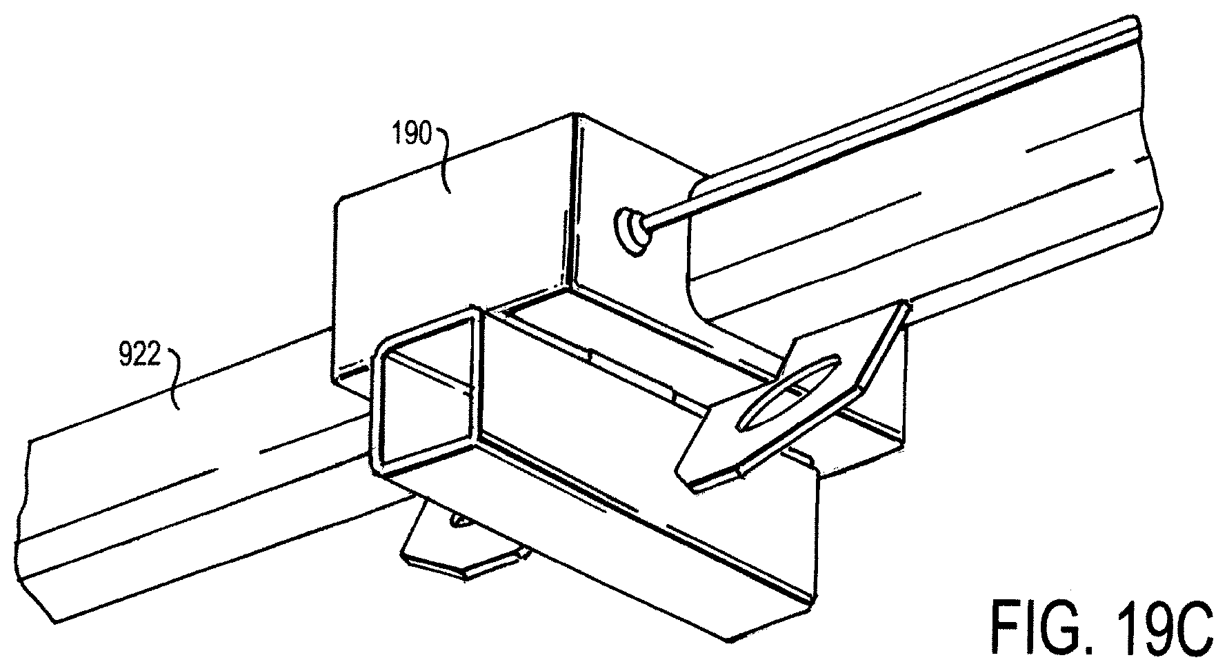
D00014
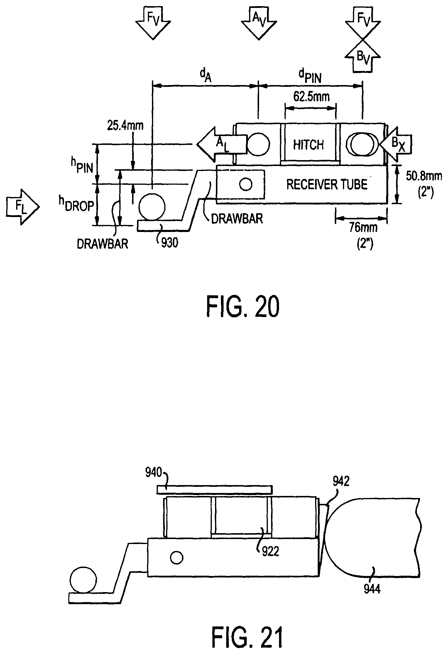
D00015
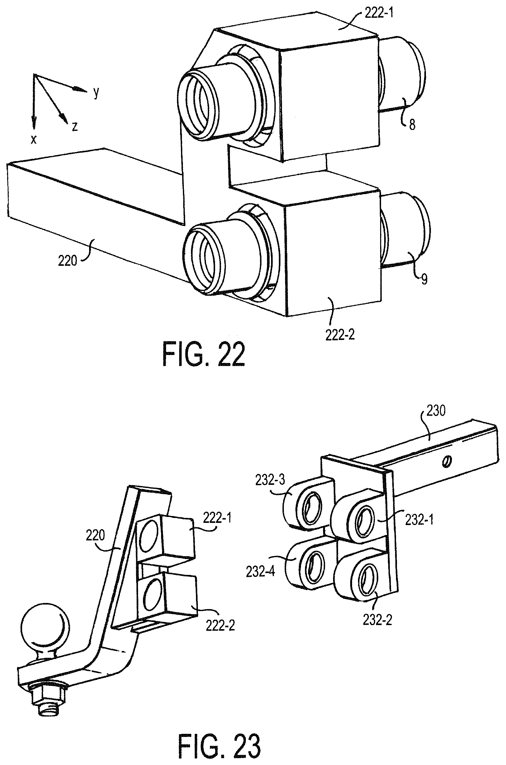
D00016
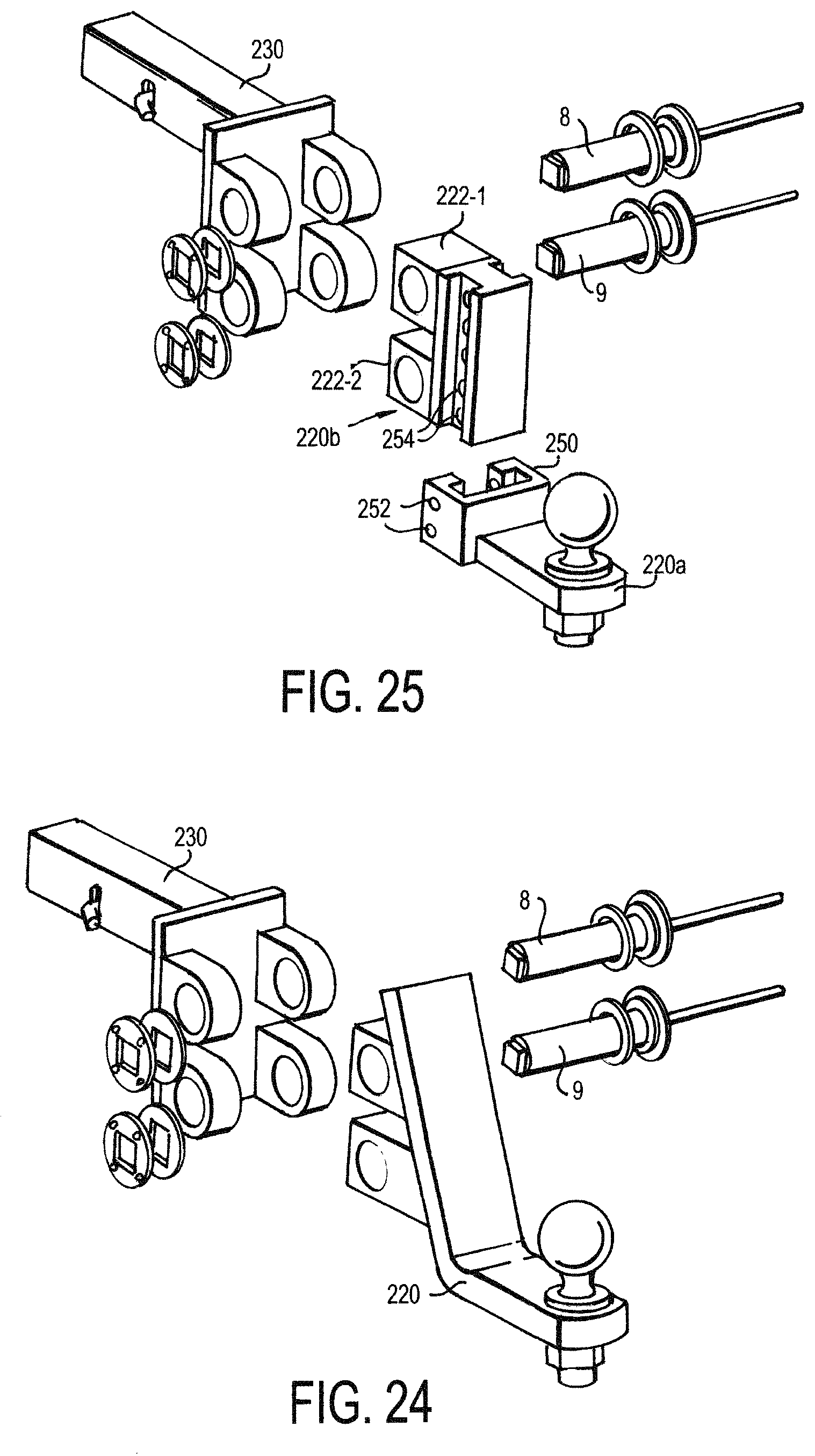
D00017

D00018
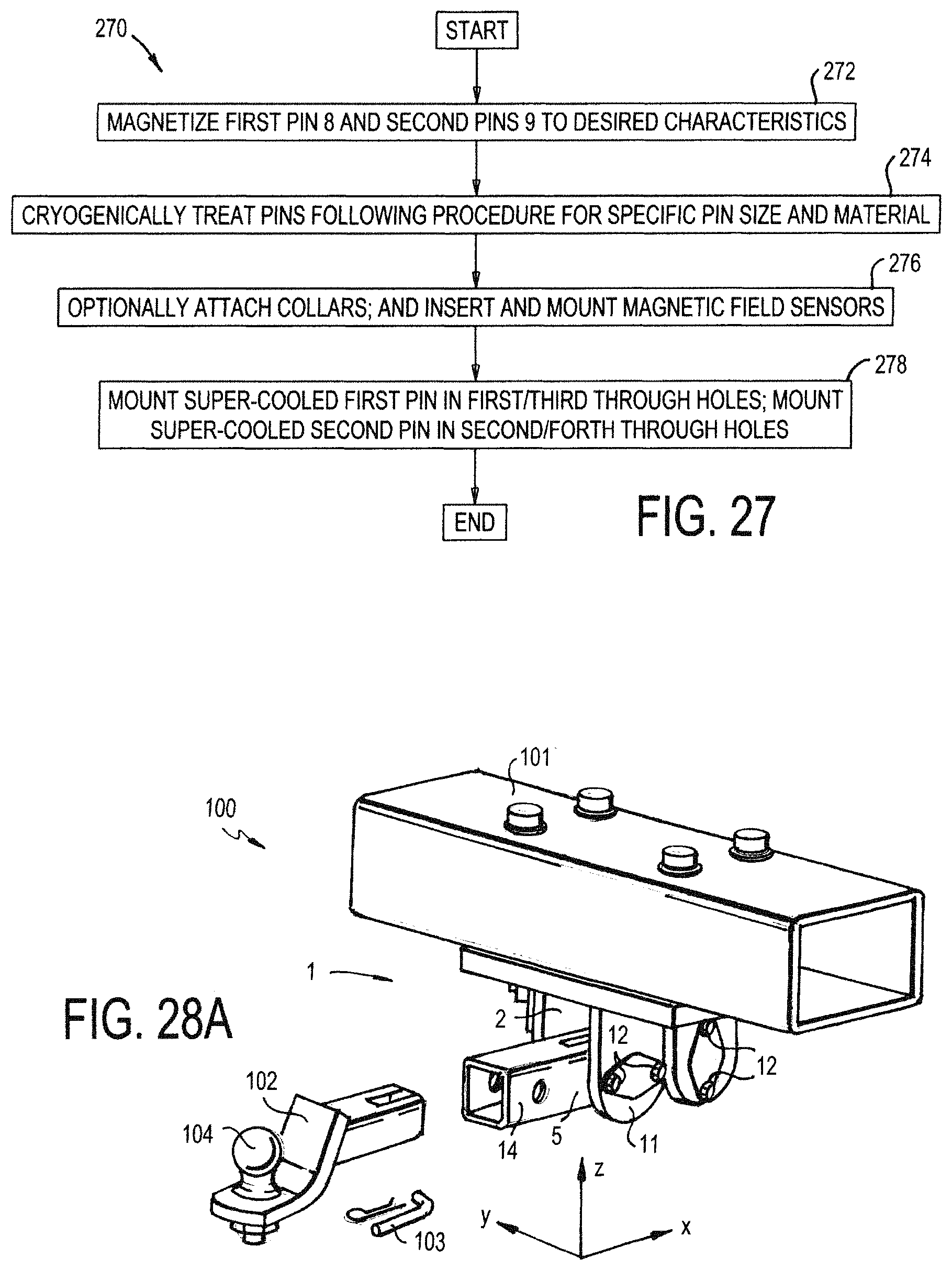
D00019
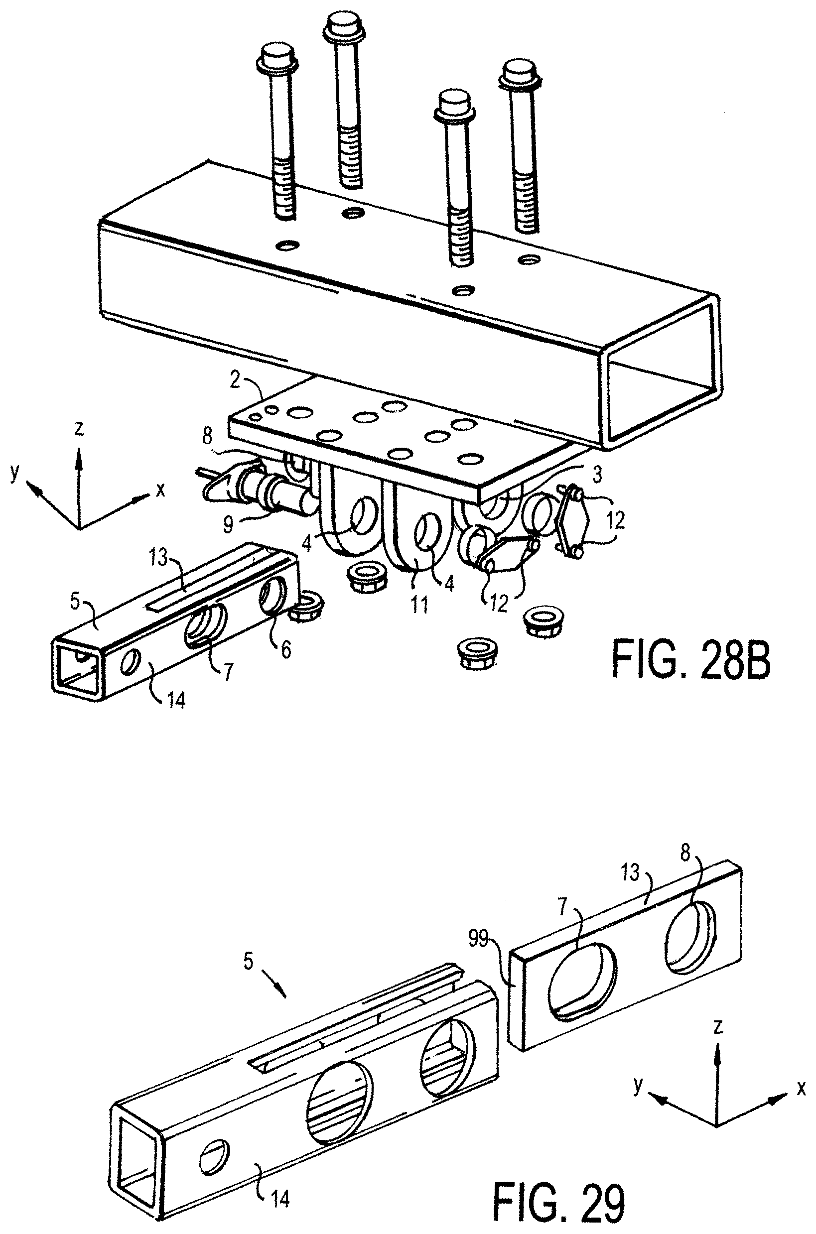
D00020
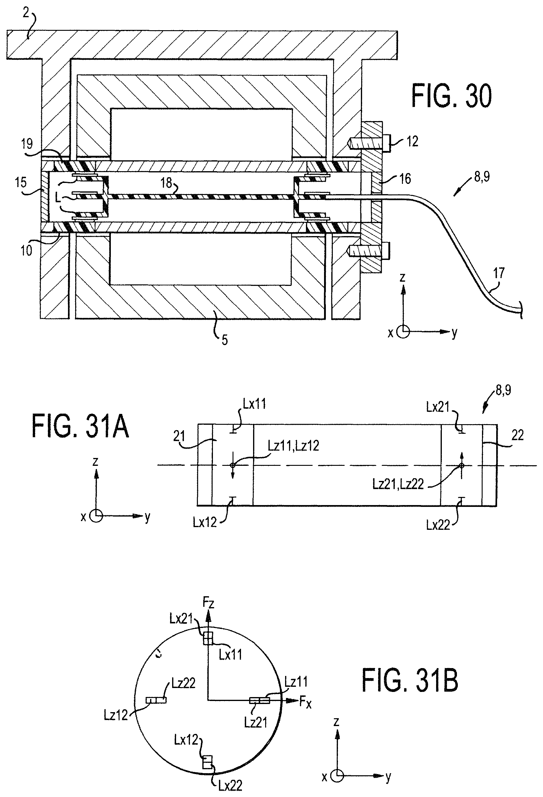
D00021
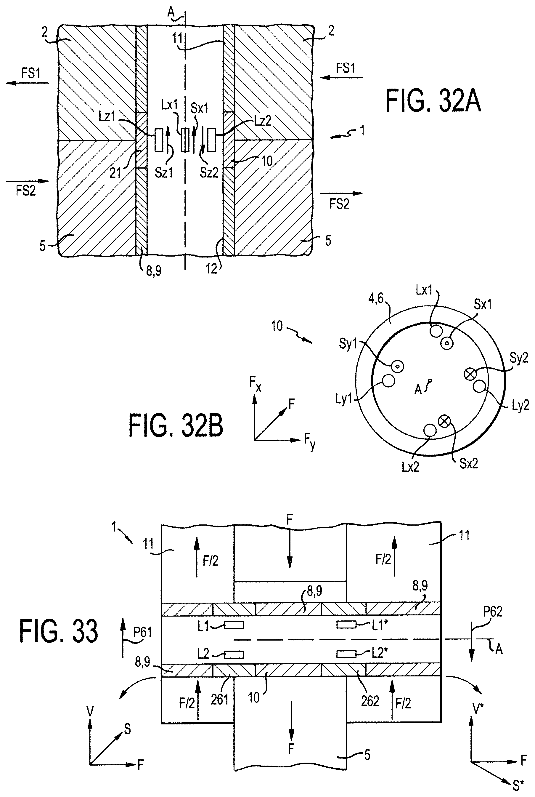
D00022

D00023
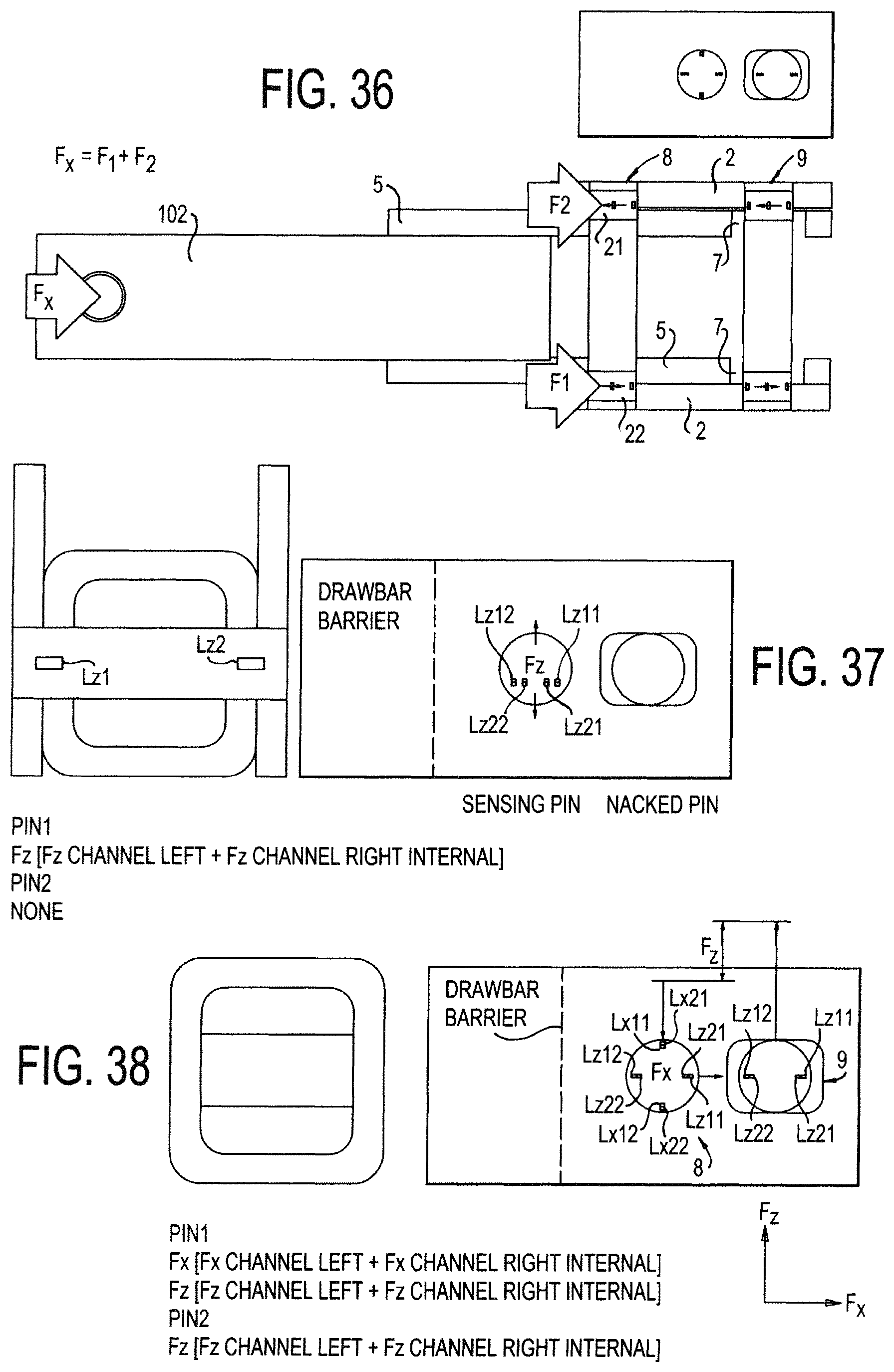
D00024

D00025

D00026
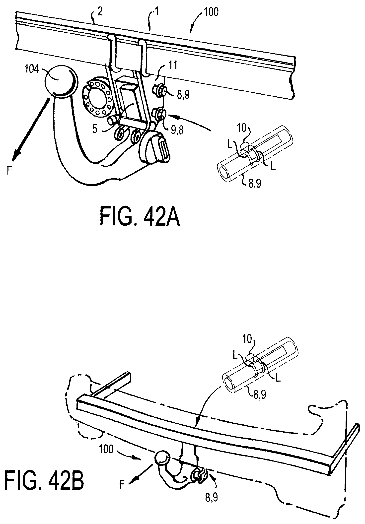
D00027

D00028

D00029
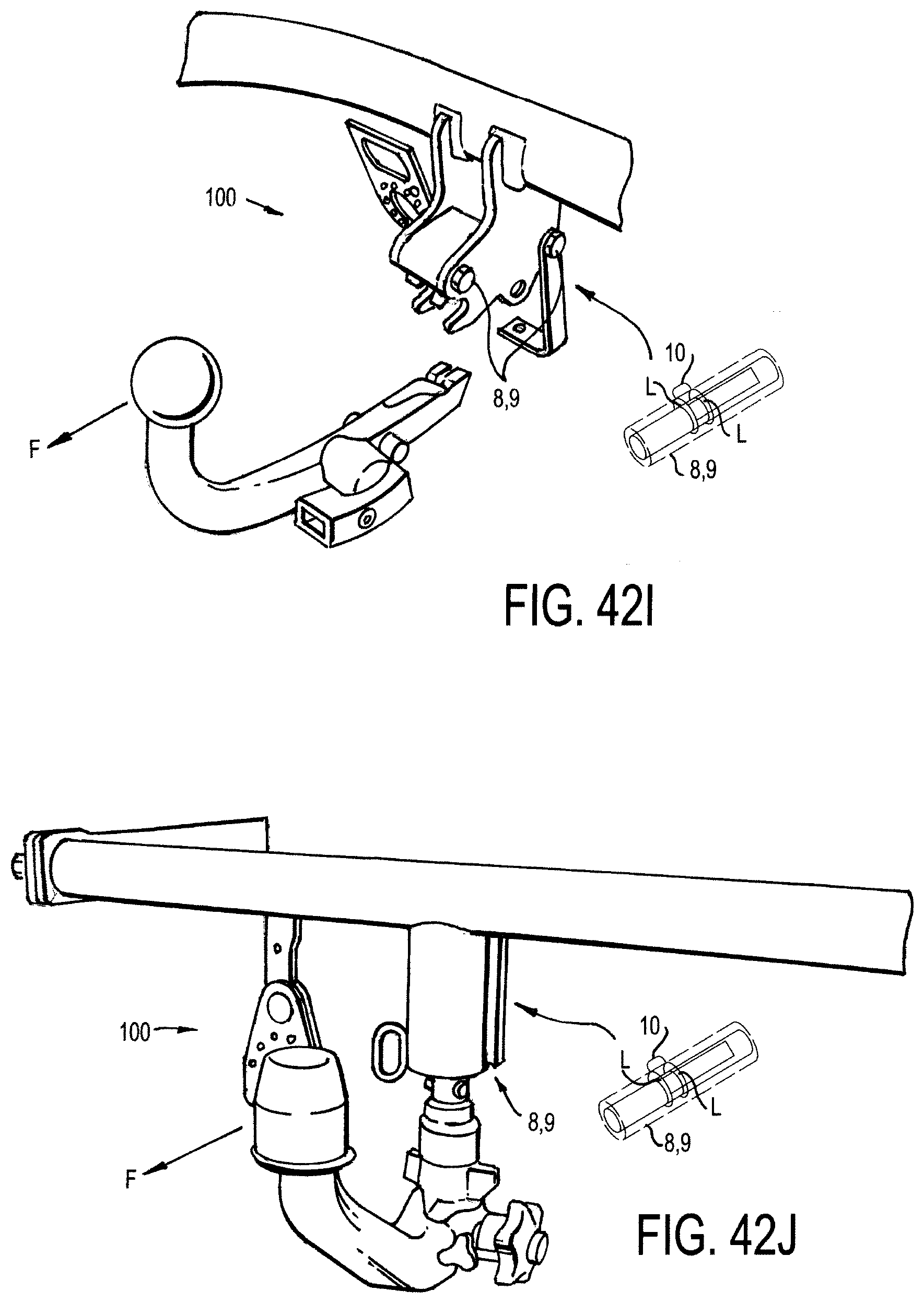
D00030

D00031
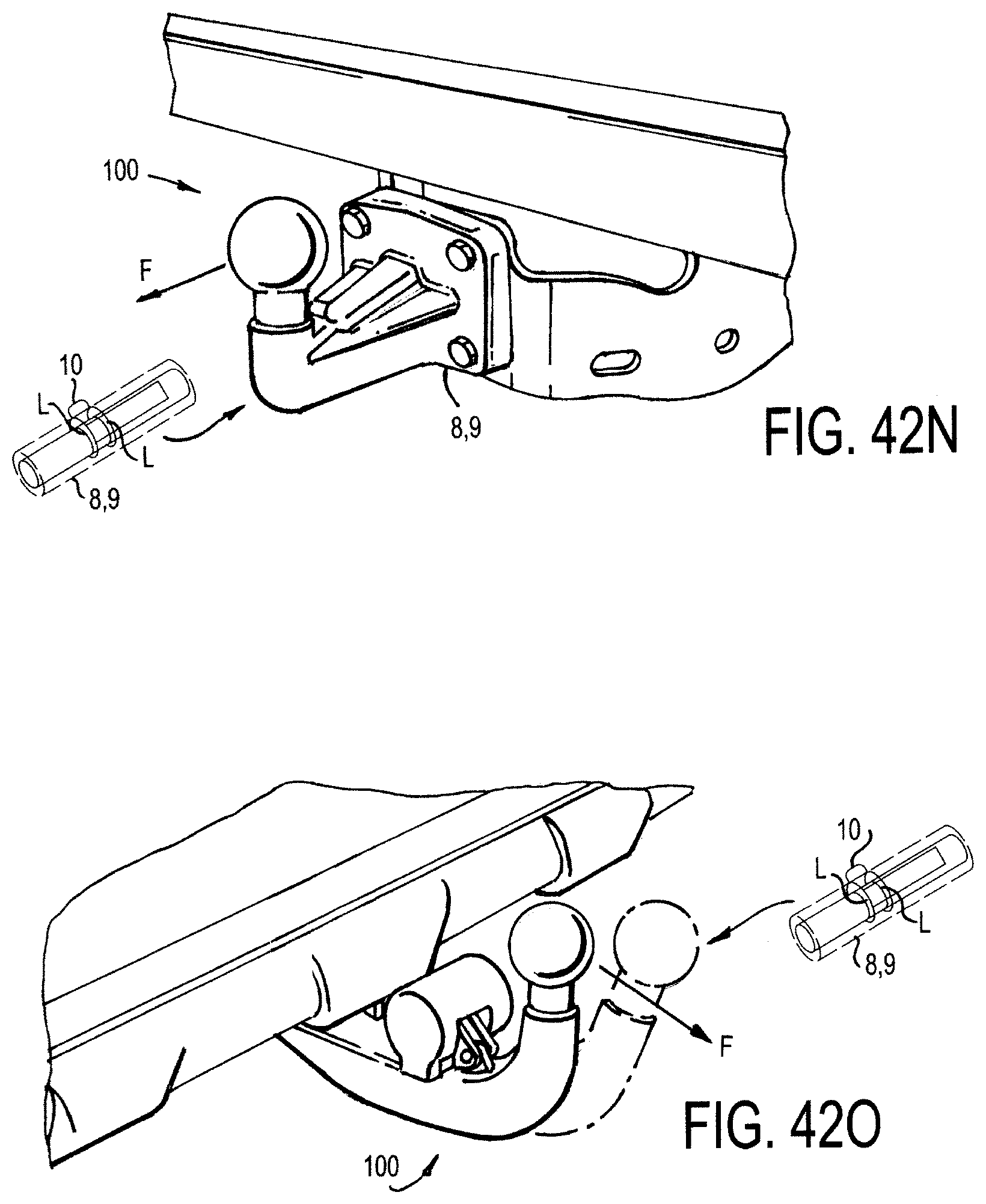
D00032

D00033

D00034

D00035

D00036

D00037

M00001

XML
uspto.report is an independent third-party trademark research tool that is not affiliated, endorsed, or sponsored by the United States Patent and Trademark Office (USPTO) or any other governmental organization. The information provided by uspto.report is based on publicly available data at the time of writing and is intended for informational purposes only.
While we strive to provide accurate and up-to-date information, we do not guarantee the accuracy, completeness, reliability, or suitability of the information displayed on this site. The use of this site is at your own risk. Any reliance you place on such information is therefore strictly at your own risk.
All official trademark data, including owner information, should be verified by visiting the official USPTO website at www.uspto.gov. This site is not intended to replace professional legal advice and should not be used as a substitute for consulting with a legal professional who is knowledgeable about trademark law.