Apparatus and methods for delivery, repositioning, and retrieval of transcatheter prosthetic valves
Ekvall , et al.
U.S. patent number 10,667,905 [Application Number 15/730,148] was granted by the patent office on 2020-06-02 for apparatus and methods for delivery, repositioning, and retrieval of transcatheter prosthetic valves. This patent grant is currently assigned to Tendyne Holdings, Inc.. The grantee listed for this patent is Tendyne Holdings, Inc.. Invention is credited to Craig A. Ekvall, Khoi Le, John F. Otte, Zachary J. Tegels, Robert M. Vidlund.


View All Diagrams
| United States Patent | 10,667,905 |
| Ekvall , et al. | June 2, 2020 |
Apparatus and methods for delivery, repositioning, and retrieval of transcatheter prosthetic valves
Abstract
Apparatus and methods are described herein for use in the delivery and deployment of a prosthetic mitral valve into a heart. In some embodiments, an apparatus includes a catheter assembly, a valve holding tube and a handle assembly. The valve holding tube is releasably couplable to a proximal end portion of the catheter assembly and to a distal end portion of the handle assembly. The handle assembly includes a housing and a delivery rod. The delivery rod is configured to be actuated to move distally relative to the housing to move a prosthetic heart valve disposed within the valve holding tube out of the valve holding tube and distally within a lumen of the elongate sheath of the catheter assembly. The catheter assembly is configured to be actuated to move proximally relative to the housing such that the prosthetic valve is disposed outside of the lumen of the elongate sheath.
| Inventors: | Ekvall; Craig A. (East Bethel, MN), Le; Khoi (Edina, MN), Otte; John F. (St. Anthony, MN), Tegels; Zachary J. (Minneapolis, MN), Vidlund; Robert M. (Forest Lake, MN) | ||||||||||
|---|---|---|---|---|---|---|---|---|---|---|---|
| Applicant: |
|
||||||||||
| Assignee: | Tendyne Holdings, Inc. (St.
Paul, MN) |
||||||||||
| Family ID: | 55806891 | ||||||||||
| Appl. No.: | 15/730,148 | ||||||||||
| Filed: | October 11, 2017 |
Prior Publication Data
| Document Identifier | Publication Date | |
|---|---|---|
| US 20180028314 A1 | Feb 1, 2018 | |
Related U.S. Patent Documents
| Application Number | Filing Date | Patent Number | Issue Date | ||
|---|---|---|---|---|---|
| PCT/US2016/027770 | Apr 15, 2016 | ||||
| 62148579 | Apr 16, 2015 | ||||
| 62312136 | Mar 23, 2016 | ||||
| Current U.S. Class: | 1/1 |
| Current CPC Class: | A61F 2/2436 (20130101); A61F 2/2433 (20130101); A61F 2/2412 (20130101); A61F 2/2466 (20130101); A61M 25/0102 (20130101); A61M 2025/0681 (20130101); A61F 2250/0039 (20130101); A61F 2/9522 (20200501); A61F 2/2418 (20130101); A61F 2/2439 (20130101); A61B 2017/00292 (20130101); A61F 2220/0016 (20130101); A61F 2230/0023 (20130101); A61F 2/9517 (20200501); A61F 2002/9534 (20130101); A61F 2/2427 (20130101); A61F 2230/005 (20130101); A61F 2002/9528 (20130101) |
| Current International Class: | A61F 2/24 (20060101); A61M 25/01 (20060101); A61F 2/95 (20130101); A61B 17/00 (20060101); A61M 25/06 (20060101) |
References Cited [Referenced By]
U.S. Patent Documents
| 2697008 | December 1954 | Ross |
| 3409013 | November 1968 | Berry |
| 3472230 | October 1969 | Fogarty et al. |
| 3476101 | November 1969 | Ross |
| 3548417 | December 1970 | Kischer |
| 3587115 | June 1971 | Shiley |
| 3657744 | April 1972 | Ersek |
| 3671979 | June 1972 | Moulopoulos |
| 3714671 | February 1973 | Edwards et al. |
| 3755823 | September 1973 | Hancock |
| 3976079 | August 1976 | Samuels et al. |
| 4003382 | January 1977 | Dyke |
| 4035849 | July 1977 | Angell et al. |
| 4056854 | November 1977 | Boretos et al. |
| 4073438 | February 1978 | Meyer |
| 4106129 | August 1978 | Carpentier et al. |
| 4222126 | September 1980 | Boretos et al. |
| 4265694 | May 1981 | Boretos et al. |
| 4297749 | November 1981 | Davis et al. |
| 4339831 | July 1982 | Johnson |
| 4343048 | August 1982 | Ross et al. |
| 4345340 | August 1982 | Rosen |
| 4373216 | February 1983 | Klawitter |
| 4406022 | September 1983 | Roy |
| 4470157 | September 1984 | Love |
| 4490859 | January 1985 | Black et al. |
| 4535483 | August 1985 | Klawitter et al. |
| 4574803 | March 1986 | Storz |
| 4585705 | April 1986 | Broderick et al. |
| 4592340 | June 1986 | Boyles |
| 4605407 | August 1986 | Black et al. |
| 4612011 | September 1986 | Kautzky |
| 4626255 | December 1986 | Reichart et al. |
| 4638886 | January 1987 | Marietta |
| 4643732 | February 1987 | Pietsch et al. |
| 4655771 | April 1987 | Wallsten |
| 4692164 | September 1987 | Dzemeshkevich et al. |
| 4733665 | March 1988 | Palmaz |
| 4759758 | July 1988 | Gabbay |
| 4762128 | August 1988 | Rosenbluth |
| 4777951 | October 1988 | Cribier et al. |
| 4787899 | November 1988 | Lazarus |
| 4787901 | November 1988 | Baykut |
| 4796629 | January 1989 | Grayzel |
| 4824180 | April 1989 | Levrai |
| 4829990 | May 1989 | Thuroff et al. |
| 4830117 | May 1989 | Capasso |
| 4851001 | July 1989 | Taheri |
| 4856516 | August 1989 | Hillstead |
| 4878495 | November 1989 | Grayzel |
| 4878906 | November 1989 | Lindemann et al. |
| 4883458 | November 1989 | Shiber |
| 4922905 | May 1990 | Strecker |
| 4923013 | May 1990 | De Gennaro |
| 4960424 | October 1990 | Grooters |
| 4966604 | October 1990 | Reiss |
| 4979939 | December 1990 | Shiber |
| 4986830 | January 1991 | Owens et al. |
| 4994077 | February 1991 | Dobben |
| 4996873 | March 1991 | Takeuchi |
| 5007896 | April 1991 | Shiber |
| 5026366 | June 1991 | Leckrone |
| 5032128 | July 1991 | Alonso |
| 5037434 | August 1991 | Lane |
| 5047041 | September 1991 | Samuels |
| 5059177 | October 1991 | Towne et al. |
| 5064435 | November 1991 | Porter |
| 5080668 | January 1992 | Bolz et al. |
| 5085635 | February 1992 | Cragg |
| 5089015 | February 1992 | Ross |
| 5152771 | October 1992 | Sabbaghian et al. |
| 5163953 | November 1992 | Vince |
| 5167628 | December 1992 | Boyles |
| 5192297 | March 1993 | Hull |
| 5201880 | April 1993 | Wright et al. |
| 5266073 | November 1993 | Wall |
| 5282847 | February 1994 | Trescony et al. |
| 5295958 | March 1994 | Shturman |
| 5306296 | April 1994 | Wright et al. |
| 5332402 | July 1994 | Teitelbaum |
| 5336616 | August 1994 | Livesey et al. |
| 5344442 | September 1994 | Deac |
| 5360444 | November 1994 | Kusuhara |
| 5364407 | November 1994 | Poll |
| 5370685 | December 1994 | Stevens |
| 5397351 | March 1995 | Pavcnik et al. |
| 5411055 | May 1995 | Kane |
| 5411552 | May 1995 | Andersen et al. |
| 5415667 | May 1995 | Frater |
| 5443446 | August 1995 | Shturman |
| 5480424 | January 1996 | Cox |
| 5500014 | March 1996 | Quijano et al. |
| 5545209 | August 1996 | Roberts et al. |
| 5545214 | August 1996 | Stevens |
| 5549665 | August 1996 | Vesely et al. |
| 5554184 | September 1996 | Machiraju |
| 5554185 | September 1996 | Block et al. |
| 5571175 | November 1996 | Vanney et al. |
| 5591185 | January 1997 | Kilmer et al. |
| 5607462 | March 1997 | Imran |
| 5607464 | March 1997 | Trescony et al. |
| 5609626 | March 1997 | Quijano et al. |
| 5639274 | June 1997 | Fischell et al. |
| 5662704 | September 1997 | Gross |
| 5665115 | September 1997 | Cragg |
| 5674279 | October 1997 | Wright et al. |
| 5697905 | December 1997 | d'Ambrosio |
| 5702368 | December 1997 | Stevens et al. |
| 5716417 | February 1998 | Girard et al. |
| 5728068 | March 1998 | Leone et al. |
| 5728151 | March 1998 | Garrison et al. |
| 5741333 | April 1998 | Frid |
| 5749890 | May 1998 | Shaknovich |
| 5756476 | May 1998 | Epstein et al. |
| 5769812 | June 1998 | Stevens et al. |
| 5792179 | August 1998 | Sideris |
| 5800508 | September 1998 | Goicoechea et al. |
| 5833673 | November 1998 | Ockuly et al. |
| 5840081 | November 1998 | Andersen et al. |
| 5855597 | January 1999 | Jayaraman |
| 5855601 | January 1999 | Bessler et al. |
| 5855602 | January 1999 | Angell |
| 5904697 | May 1999 | Gifford, III et al. |
| 5925063 | July 1999 | Khosravi |
| 5957949 | September 1999 | Leonhardt et al. |
| 5968052 | October 1999 | Sullivan, III et al. |
| 5968068 | October 1999 | Dehdashtian et al. |
| 5972030 | October 1999 | Garrison et al. |
| 5993481 | November 1999 | Marcade et al. |
| 6027525 | February 2000 | Suh et al. |
| 6042607 | March 2000 | Williamson, IV et al. |
| 6045497 | April 2000 | Schweich, Jr. et al. |
| 6063112 | May 2000 | Sgro |
| 6077214 | June 2000 | Mortier et al. |
| 6099508 | August 2000 | Bousquet |
| 6132473 | October 2000 | Williams et al. |
| 6168614 | January 2001 | Andersen et al. |
| 6171335 | January 2001 | Wheatley et al. |
| 6174327 | January 2001 | Mertens et al. |
| 6183411 | February 2001 | Mortier et al. |
| 6210408 | April 2001 | Chandrasekaran et al. |
| 6217585 | April 2001 | Houser et al. |
| 6221091 | April 2001 | Khosravi |
| 6231602 | May 2001 | Carpentier et al. |
| 6245102 | June 2001 | Jayaraman |
| 6260552 | July 2001 | Mortier et al. |
| 6261222 | July 2001 | Schweich, Jr. et al. |
| 6264602 | July 2001 | Mortier et al. |
| 6287339 | September 2001 | Vazquez et al. |
| 6299637 | October 2001 | Shaolian et al. |
| 6302906 | October 2001 | Goicoechea et al. |
| 6312465 | November 2001 | Griffin et al. |
| 6332893 | December 2001 | Mortier et al. |
| 6350277 | February 2002 | Kocur |
| 6358277 | March 2002 | Duran |
| 6379372 | April 2002 | Dehdashtian et al. |
| 6402679 | June 2002 | Mortier et al. |
| 6402680 | June 2002 | Mortier et al. |
| 6402781 | June 2002 | Langberg et al. |
| 6406420 | June 2002 | McCarthy et al. |
| 6425916 | July 2002 | Garrison et al. |
| 6440164 | August 2002 | DiMatteo et al. |
| 6454799 | September 2002 | Schreck |
| 6458153 | October 2002 | Bailey et al. |
| 6461382 | October 2002 | Cao |
| 6468660 | October 2002 | Ogle et al. |
| 6482228 | November 2002 | Norred |
| 6488704 | December 2002 | Connelly et al. |
| 6537198 | March 2003 | Vidlund et al. |
| 6540782 | April 2003 | Snyders |
| 6569196 | May 2003 | Vesely |
| 6575252 | June 2003 | Reed |
| 6582462 | June 2003 | Andersen et al. |
| 6605112 | August 2003 | Moll et al. |
| 6616684 | September 2003 | Vidlund et al. |
| 6622730 | September 2003 | Ekvall et al. |
| 6629534 | October 2003 | St. Goar et al. |
| 6629921 | October 2003 | Schweich, Jr. et al. |
| 6648077 | November 2003 | Hoffman |
| 6648921 | November 2003 | Anderson et al. |
| 6652578 | November 2003 | Bailey et al. |
| 6669724 | December 2003 | Park et al. |
| 6706065 | March 2004 | Langberg et al. |
| 6709456 | March 2004 | Langberg et al. |
| 6723038 | April 2004 | Schroeder et al. |
| 6726715 | April 2004 | Sutherland |
| 6730118 | May 2004 | Spenser et al. |
| 6733525 | May 2004 | Yang et al. |
| 6740105 | May 2004 | Yodfat et al. |
| 6746401 | June 2004 | Panescu |
| 6746471 | June 2004 | Mortier et al. |
| 6752813 | June 2004 | Goldfarb et al. |
| 6764510 | July 2004 | Vidlund et al. |
| 6797002 | September 2004 | Spence et al. |
| 6810882 | November 2004 | Langberg et al. |
| 6830584 | December 2004 | Seguin |
| 6854668 | February 2005 | Wancho et al. |
| 6855144 | February 2005 | Lesh |
| 6858001 | February 2005 | Aboul-Hosn |
| 6890353 | May 2005 | Cohn et al. |
| 6893460 | May 2005 | Spenser et al. |
| 6896690 | May 2005 | Lambrecht et al. |
| 6908424 | June 2005 | Mortier et al. |
| 6908481 | June 2005 | Cribier |
| 6936067 | August 2005 | Buchanan |
| 6945996 | September 2005 | Sedransk |
| 6955175 | October 2005 | Stevens et al. |
| 6974476 | December 2005 | McGuckin, Jr. et al. |
| 6976543 | December 2005 | Fischer |
| 6997950 | February 2006 | Chawla |
| 7018406 | March 2006 | Seguin et al. |
| 7018408 | March 2006 | Bailey et al. |
| 7044905 | May 2006 | Vidlund et al. |
| 7060021 | June 2006 | Wilk |
| 7077862 | July 2006 | Vidlund et al. |
| 7087064 | August 2006 | Hyde |
| 7100614 | September 2006 | Stevens et al. |
| 7101395 | September 2006 | Tremulis et al. |
| 7108717 | September 2006 | Freidberg |
| 7112219 | September 2006 | Vidlund et al. |
| 7115141 | October 2006 | Menz et al. |
| 7141064 | November 2006 | Scott et al. |
| 7175656 | February 2007 | Khairkhahan |
| 7198646 | April 2007 | Figulla et al. |
| 7201772 | April 2007 | Schwammenthal et al. |
| 7247134 | July 2007 | Vidlund et al. |
| 7252682 | August 2007 | Seguin |
| 7267686 | September 2007 | DiMatteo et al. |
| 7275604 | October 2007 | Wall |
| 7276078 | October 2007 | Spenser et al. |
| 7276084 | October 2007 | Yang et al. |
| 7316706 | January 2008 | Bloom et al. |
| 7318278 | January 2008 | Zhang et al. |
| 7326236 | February 2008 | Andreas et al. |
| 7329278 | February 2008 | Seguin et al. |
| 7331991 | February 2008 | Kheradvar et al. |
| 7335213 | February 2008 | Hyde et al. |
| 7374571 | May 2008 | Pease et al. |
| 7377941 | May 2008 | Rhee et al. |
| 7381210 | June 2008 | Zarbatany et al. |
| 7381218 | June 2008 | Schreck |
| 7393360 | July 2008 | Spenser et al. |
| 7404824 | July 2008 | Webler et al. |
| 7416554 | August 2008 | Lam et al. |
| 7422072 | September 2008 | Dade |
| 7429269 | September 2008 | Schwammenthal et al. |
| 7442204 | October 2008 | Schwammenthal et al. |
| 7445631 | November 2008 | Salahieh et al. |
| 7462191 | December 2008 | Spenser et al. |
| 7470285 | December 2008 | Nugent et al. |
| 7500989 | March 2009 | Solem et al. |
| 7503931 | March 2009 | Kowalsky et al. |
| 7510572 | March 2009 | Gabbay |
| 7510575 | March 2009 | Spenser et al. |
| 7513908 | April 2009 | Lattouf |
| 7524330 | April 2009 | Berreklouw |
| 7527647 | May 2009 | Spence |
| 7534260 | May 2009 | Lattouf |
| 7556646 | July 2009 | Yang et al. |
| 7579381 | August 2009 | Dove |
| 7585321 | September 2009 | Cribier |
| 7591847 | September 2009 | Navia et al. |
| 7618446 | November 2009 | Andersen et al. |
| 7618447 | November 2009 | Case et al. |
| 7621948 | November 2009 | Herrmann et al. |
| 7632304 | December 2009 | Park |
| 7632308 | December 2009 | Loulmet |
| 7635386 | December 2009 | Gammie |
| 7674222 | March 2010 | Nikolic et al. |
| 7674286 | March 2010 | Alfieri et al. |
| 7695510 | April 2010 | Bloom et al. |
| 7708775 | May 2010 | Rowe et al. |
| 7748389 | July 2010 | Salahieh et al. |
| 7766961 | August 2010 | Patel et al. |
| 7789909 | September 2010 | Andersen et al. |
| 7803168 | September 2010 | Gifford et al. |
| 7803184 | September 2010 | McGuckin, Jr. et al. |
| 7803185 | September 2010 | Gabbay |
| 7806928 | October 2010 | Rowe et al. |
| 7837727 | November 2010 | Goetz et al. |
| 7854762 | December 2010 | Speziali et al. |
| 7892281 | February 2011 | Seguin et al. |
| 7896915 | March 2011 | Guyenot et al. |
| 7901454 | March 2011 | Kapadia et al. |
| 7927370 | April 2011 | Webler et al. |
| 7931630 | April 2011 | Nishtala et al. |
| 7942928 | May 2011 | Webler et al. |
| 7955247 | June 2011 | Levine et al. |
| 7955385 | June 2011 | Crittenden |
| 7972378 | July 2011 | Tabor et al. |
| 7988727 | August 2011 | Santamore et al. |
| 7993394 | August 2011 | Hariton et al. |
| 8007992 | August 2011 | Tian et al. |
| 8029556 | October 2011 | Rowe |
| 8043368 | October 2011 | Crabtree |
| 8052749 | November 2011 | Salahieh et al. |
| 8052750 | November 2011 | Tuval et al. |
| 8052751 | November 2011 | Aklog et al. |
| 8062355 | November 2011 | Figulla et al. |
| 8062359 | November 2011 | Marquez et al. |
| 8070802 | December 2011 | Lamphere et al. |
| 8109996 | February 2012 | Stacchino et al. |
| 8142495 | March 2012 | Hasenkam et al. |
| 8152821 | April 2012 | Gambale et al. |
| 8157810 | April 2012 | Case et al. |
| 8167932 | May 2012 | Bourang et al. |
| 8167934 | May 2012 | Styrc et al. |
| 8187299 | May 2012 | Goldfarb et al. |
| 8206439 | June 2012 | Gomez Duran |
| 8216301 | July 2012 | Bonhoeffer et al. |
| 8226711 | July 2012 | Mortier et al. |
| 8236045 | August 2012 | Benichou et al. |
| 8241274 | August 2012 | Keogh et al. |
| 8252051 | August 2012 | Chau et al. |
| 8303653 | November 2012 | Bonhoeffer et al. |
| 8308796 | November 2012 | Lashinski et al. |
| 8323334 | December 2012 | Deem et al. |
| 8353955 | January 2013 | Styrc et al. |
| RE44075 | March 2013 | Williamson et al. |
| 8449599 | May 2013 | Chau et al. |
| 8454656 | June 2013 | Tuval |
| 8470028 | June 2013 | Thornton et al. |
| 8480730 | July 2013 | Maurer et al. |
| 8486138 | July 2013 | Vesely |
| 8506623 | August 2013 | Wilson et al. |
| 8506624 | August 2013 | Vidlund et al. |
| 8578705 | November 2013 | Sindano et al. |
| 8579913 | November 2013 | Nielsen |
| 8579963 | November 2013 | Tabor |
| 8591573 | November 2013 | Barone |
| 8591576 | November 2013 | Hasenkam et al. |
| 8597347 | December 2013 | Maurer et al. |
| 8685086 | April 2014 | Navia et al. |
| 8790394 | July 2014 | Miller et al. |
| 8845717 | September 2014 | Khairkhahan et al. |
| 8888843 | November 2014 | Khairkhahan et al. |
| 8900214 | December 2014 | Nance et al. |
| 8900295 | December 2014 | Migliazza et al. |
| 8926696 | January 2015 | Cabiri et al. |
| 8932342 | January 2015 | McHugo et al. |
| 8932348 | January 2015 | Solem et al. |
| 8945208 | February 2015 | Jimenez et al. |
| 8956407 | February 2015 | Macoviak et al. |
| 8979922 | March 2015 | Jayasinghe et al. |
| 8986376 | March 2015 | Solem |
| 9011522 | April 2015 | Annest |
| 9023099 | May 2015 | Duffy et al. |
| 9034032 | May 2015 | McLean et al. |
| 9034033 | May 2015 | McLean et al. |
| 9039757 | May 2015 | McLean et al. |
| 9039759 | May 2015 | Alkhatib et al. |
| 9078749 | July 2015 | Lutter et al. |
| 9084676 | July 2015 | Chau et al. |
| 9095433 | August 2015 | Lutter et al. |
| 9125742 | September 2015 | Yoganathan et al. |
| 9149357 | October 2015 | Seguin |
| 9161837 | October 2015 | Kapadia |
| 9168137 | October 2015 | Subramanian et al. |
| 9232998 | January 2016 | Wilson et al. |
| 9232999 | January 2016 | Maurer et al. |
| 9241702 | January 2016 | Maisano et al. |
| 9254192 | February 2016 | Lutter et al. |
| 9265608 | February 2016 | Miller et al. |
| 9289295 | March 2016 | Aklog et al. |
| 9289297 | March 2016 | Wilson et al. |
| 9345573 | May 2016 | Nyuli et al. |
| 9364325 | June 2016 | Alon et al. |
| 9480557 | November 2016 | Pellegrini et al. |
| 9480559 | November 2016 | Vidlund et al. |
| 9526611 | December 2016 | Tegels et al. |
| 9597181 | March 2017 | Christianson et al. |
| 9610159 | April 2017 | Christianson et al. |
| 9675454 | June 2017 | Vidlund et al. |
| 9730792 | August 2017 | Lutter et al. |
| 2001/0018611 | August 2001 | Solem et al. |
| 2001/0021872 | September 2001 | Bailey et al. |
| 2001/0025171 | September 2001 | Mortier et al. |
| 2002/0010427 | January 2002 | Scarfone et al. |
| 2002/0116054 | August 2002 | Lundell et al. |
| 2002/0139056 | October 2002 | Finnell |
| 2002/0151961 | October 2002 | Lashinski et al. |
| 2002/0161377 | October 2002 | Rabkin |
| 2002/0173842 | November 2002 | Buchanan |
| 2003/0010509 | January 2003 | Hoffman |
| 2003/0036698 | February 2003 | Kohler et al. |
| 2003/0050694 | March 2003 | Yang et al. |
| 2003/0078652 | April 2003 | Sutherland |
| 2003/0100939 | May 2003 | Yodfat et al. |
| 2003/0105519 | June 2003 | Fasol et al. |
| 2003/0105520 | June 2003 | Alferness et al. |
| 2003/0120340 | June 2003 | Liska et al. |
| 2003/0130731 | July 2003 | Vidlund et al. |
| 2003/0149476 | August 2003 | Damm et al. |
| 2003/0212454 | November 2003 | Scott et al. |
| 2004/0039436 | February 2004 | Spenser et al. |
| 2004/0049266 | March 2004 | Anduiza et al. |
| 2004/0064014 | April 2004 | Melvin et al. |
| 2004/0092858 | May 2004 | Wilson et al. |
| 2004/0093075 | May 2004 | Kuehne |
| 2004/0097865 | May 2004 | Anderson et al. |
| 2004/0127983 | July 2004 | Mortier et al. |
| 2004/0133263 | July 2004 | Dusbabek et al. |
| 2004/0147958 | July 2004 | Lam et al. |
| 2004/0152947 | August 2004 | Schroeder et al. |
| 2004/0162610 | August 2004 | Liska et al. |
| 2004/0163828 | August 2004 | Silverstein et al. |
| 2004/0181239 | September 2004 | Dorn et al. |
| 2004/0186565 | September 2004 | Schreck |
| 2004/0186566 | September 2004 | Hindrichs et al. |
| 2004/0260317 | December 2004 | Bloom et al. |
| 2004/0260389 | December 2004 | Case et al. |
| 2005/0004652 | January 2005 | van der Burg et al. |
| 2005/0004666 | January 2005 | Alfieri et al. |
| 2005/0075727 | April 2005 | Wheatley |
| 2005/0080402 | April 2005 | Santamore et al. |
| 2005/0096498 | May 2005 | Houser et al. |
| 2005/0107661 | May 2005 | Lau et al. |
| 2005/0113798 | May 2005 | Slater et al. |
| 2005/0113810 | May 2005 | Houser et al. |
| 2005/0113811 | May 2005 | Houser et al. |
| 2005/0119519 | June 2005 | Girard et al. |
| 2005/0121206 | June 2005 | Dolan |
| 2005/0125012 | June 2005 | Houser et al. |
| 2005/0137688 | June 2005 | Salahieh et al. |
| 2005/0137695 | June 2005 | Salahieh et al. |
| 2005/0137698 | June 2005 | Salahieh et al. |
| 2005/0148815 | July 2005 | Mortier et al. |
| 2005/0177180 | August 2005 | Kaganov et al. |
| 2005/0197695 | September 2005 | Stacchino et al. |
| 2005/0203614 | September 2005 | Forster et al. |
| 2005/0203615 | September 2005 | Forster et al. |
| 2005/0203617 | September 2005 | Forster et al. |
| 2005/0234546 | October 2005 | Nugent et al. |
| 2005/0240200 | October 2005 | Bergheim |
| 2005/0251209 | November 2005 | Saadat et al. |
| 2005/0256567 | November 2005 | Lim et al. |
| 2005/0288766 | December 2005 | Plain et al. |
| 2006/0004442 | January 2006 | Spenser et al. |
| 2006/0025784 | February 2006 | Starksen et al. |
| 2006/0025857 | February 2006 | Bergheim et al. |
| 2006/0030885 | February 2006 | Hyde |
| 2006/0042803 | March 2006 | Gallaher |
| 2006/0047338 | March 2006 | Jenson et al. |
| 2006/0052868 | March 2006 | Mortier et al. |
| 2006/0058872 | March 2006 | Salahieh et al. |
| 2006/0094983 | May 2006 | Burbank et al. |
| 2006/0129025 | June 2006 | Levine et al. |
| 2006/0142784 | June 2006 | Kontos |
| 2006/0161040 | July 2006 | McCarthy et al. |
| 2006/0161249 | July 2006 | Realyvasquez et al. |
| 2006/0167541 | July 2006 | Lattouf |
| 2006/0195134 | August 2006 | Crittenden |
| 2006/0195183 | August 2006 | Navia et al. |
| 2006/0229708 | October 2006 | Powell et al. |
| 2006/0229719 | October 2006 | Marquez et al. |
| 2006/0241745 | October 2006 | Solem |
| 2006/0247491 | November 2006 | Vidlund et al. |
| 2006/0259135 | November 2006 | Navia et al. |
| 2006/0259136 | November 2006 | Nguyen et al. |
| 2006/0259137 | November 2006 | Artof et al. |
| 2006/0276874 | December 2006 | Wilson et al. |
| 2006/0282161 | December 2006 | Huynh et al. |
| 2006/0287716 | December 2006 | Banbury et al. |
| 2006/0287717 | December 2006 | Rowe et al. |
| 2007/0005131 | January 2007 | Taylor |
| 2007/0005231 | January 2007 | Seguchi |
| 2007/0010877 | January 2007 | Salahieh et al. |
| 2007/0016286 | January 2007 | Herrmann et al. |
| 2007/0016288 | January 2007 | Gurskis et al. |
| 2007/0027535 | February 2007 | Purdy et al. |
| 2007/0038291 | February 2007 | Case et al. |
| 2007/0050020 | March 2007 | Spence |
| 2007/0061010 | March 2007 | Hauser et al. |
| 2007/0066863 | March 2007 | Rafiee et al. |
| 2007/0073387 | March 2007 | Forster et al. |
| 2007/0078297 | April 2007 | Rafiee et al. |
| 2007/0083076 | April 2007 | Lichtenstein |
| 2007/0083259 | April 2007 | Bloom et al. |
| 2007/0093890 | April 2007 | Eliasen et al. |
| 2007/0100439 | May 2007 | Cangialosi et al. |
| 2007/0112422 | May 2007 | Dehdashtian |
| 2007/0112425 | May 2007 | Schaller et al. |
| 2007/0118151 | May 2007 | Davidson |
| 2007/0118154 | May 2007 | Crabtree |
| 2007/0118210 | May 2007 | Pinchuk |
| 2007/0118213 | May 2007 | Loulmet |
| 2007/0142906 | June 2007 | Figulla et al. |
| 2007/0161846 | July 2007 | Nikolic et al. |
| 2007/0162103 | July 2007 | Case et al. |
| 2007/0168024 | July 2007 | Khairkhahan |
| 2007/0185565 | August 2007 | Schwammenthal et al. |
| 2007/0185571 | August 2007 | Kapadia et al. |
| 2007/0203575 | August 2007 | Forster et al. |
| 2007/0213813 | September 2007 | Von Segesser et al. |
| 2007/0215362 | September 2007 | Rodgers |
| 2007/0221388 | September 2007 | Johnson |
| 2007/0233239 | October 2007 | Navia et al. |
| 2007/0239265 | October 2007 | Birdsall |
| 2007/0256843 | November 2007 | Pahila |
| 2007/0265658 | November 2007 | Nelson et al. |
| 2007/0267202 | November 2007 | Mariller |
| 2007/0270932 | November 2007 | Headley et al. |
| 2007/0270943 | November 2007 | Solem et al. |
| 2007/0293944 | December 2007 | Spenser et al. |
| 2008/0009940 | January 2008 | Cribier |
| 2008/0065011 | March 2008 | Marchand |
| 2008/0071361 | March 2008 | Tuval et al. |
| 2008/0071362 | March 2008 | Tuval et al. |
| 2008/0071363 | March 2008 | Tuval et al. |
| 2008/0071366 | March 2008 | Tuval et al. |
| 2008/0071368 | March 2008 | Tuval et al. |
| 2008/0071369 | March 2008 | Tuval et al. |
| 2008/0082163 | April 2008 | Woo |
| 2008/0082166 | April 2008 | Styrc et al. |
| 2008/0091264 | April 2008 | Machold et al. |
| 2008/0114442 | May 2008 | Mitchell et al. |
| 2008/0125861 | May 2008 | Webler et al. |
| 2008/0147179 | June 2008 | Cai et al. |
| 2008/0154355 | June 2008 | Benichou et al. |
| 2008/0154356 | June 2008 | Obermiller et al. |
| 2008/0161911 | July 2008 | Revuelta et al. |
| 2008/0172035 | July 2008 | Starksen et al. |
| 2008/0177381 | July 2008 | Navia et al. |
| 2008/0183203 | July 2008 | Fitzgerald et al. |
| 2008/0188928 | August 2008 | Salahieh et al. |
| 2008/0208328 | August 2008 | Antocci et al. |
| 2008/0208332 | August 2008 | Lamphere et al. |
| 2008/0221672 | September 2008 | Lamphere et al. |
| 2008/0243150 | October 2008 | Starksen et al. |
| 2008/0243245 | October 2008 | Thambar et al. |
| 2008/0255660 | October 2008 | Guyenot et al. |
| 2008/0255661 | October 2008 | Straubinger et al. |
| 2008/0281411 | November 2008 | Berreklouw |
| 2008/0288060 | November 2008 | Kaye et al. |
| 2008/0293996 | November 2008 | Evans et al. |
| 2009/0005863 | January 2009 | Goetz et al. |
| 2009/0048668 | February 2009 | Wilson et al. |
| 2009/0054968 | February 2009 | Bonhoeffer et al. |
| 2009/0054974 | February 2009 | McGuckin, Jr. et al. |
| 2009/0054976 | February 2009 | Tuval |
| 2009/0062908 | March 2009 | Bonhoeffer et al. |
| 2009/0076598 | March 2009 | Salahieh et al. |
| 2009/0082619 | March 2009 | De Marchena |
| 2009/0088836 | April 2009 | Bishop et al. |
| 2009/0099410 | April 2009 | De Marchena |
| 2009/0112309 | April 2009 | Jaramillo et al. |
| 2009/0131849 | May 2009 | Maurer et al. |
| 2009/0132035 | May 2009 | Roth et al. |
| 2009/0137861 | May 2009 | Goldberg et al. |
| 2009/0138079 | May 2009 | Tuval et al. |
| 2009/0157175 | June 2009 | Benichou |
| 2009/0164005 | June 2009 | Dove et al. |
| 2009/0171432 | July 2009 | Von Segesser et al. |
| 2009/0171447 | July 2009 | Von Segesser et al. |
| 2009/0171456 | July 2009 | Kveen et al. |
| 2009/0177266 | July 2009 | Powell et al. |
| 2009/0192601 | July 2009 | Rafiee |
| 2009/0210052 | August 2009 | Forster et al. |
| 2009/0216322 | August 2009 | Le et al. |
| 2009/0222076 | September 2009 | Figulla et al. |
| 2009/0224529 | September 2009 | Gill |
| 2009/0234318 | September 2009 | Loulmet et al. |
| 2009/0234435 | September 2009 | Johnson et al. |
| 2009/0234443 | September 2009 | Ottma et al. |
| 2009/0240320 | September 2009 | Tuval et al. |
| 2009/0248149 | October 2009 | Gabbay |
| 2009/0276040 | November 2009 | Rowe et al. |
| 2009/0281619 | November 2009 | Le et al. |
| 2009/0287299 | November 2009 | Tabor et al. |
| 2009/0319037 | December 2009 | Rowe et al. |
| 2009/0326575 | December 2009 | Galdonik et al. |
| 2010/0016958 | January 2010 | St. Goar et al. |
| 2010/0021382 | January 2010 | Dorshow et al. |
| 2010/0023117 | January 2010 | Yoganathan et al. |
| 2010/0036479 | February 2010 | Hill et al. |
| 2010/0049313 | February 2010 | Alon et al. |
| 2010/0082094 | April 2010 | Quadri et al. |
| 2010/0161041 | June 2010 | Maisano et al. |
| 2010/0168839 | July 2010 | Braido et al. |
| 2010/0179641 | July 2010 | Ryan et al. |
| 2010/0185277 | July 2010 | Braido et al. |
| 2010/0185278 | July 2010 | Schankereli |
| 2010/0191326 | July 2010 | Alkhatib |
| 2010/0192402 | August 2010 | Yamaguchi et al. |
| 2010/0204781 | August 2010 | Alkhatib |
| 2010/0210899 | August 2010 | Schankereli |
| 2010/0217382 | August 2010 | Chau et al. |
| 2010/0249489 | September 2010 | Jarvik |
| 2010/0249923 | September 2010 | Alkhatib et al. |
| 2010/0280604 | November 2010 | Zipory et al. |
| 2010/0286768 | November 2010 | Alkhatib |
| 2010/0298755 | November 2010 | McNamara et al. |
| 2010/0298931 | November 2010 | Quadri et al. |
| 2011/0004296 | January 2011 | Lutter et al. |
| 2011/0015616 | January 2011 | Straubinger et al. |
| 2011/0015728 | January 2011 | Jimenez et al. |
| 2011/0015729 | January 2011 | Jimenez et al. |
| 2011/0029072 | February 2011 | Gabbay |
| 2011/0046712 | February 2011 | Melsheimer |
| 2011/0066231 | March 2011 | Cartledge et al. |
| 2011/0112632 | May 2011 | Chau et al. |
| 2011/0137397 | June 2011 | Chau et al. |
| 2011/0137408 | June 2011 | Bergheim |
| 2011/0224655 | September 2011 | Asirvatham et al. |
| 2011/0224678 | September 2011 | Gabbay |
| 2011/0224728 | September 2011 | Martin et al. |
| 2011/0224784 | September 2011 | Quinn |
| 2011/0245911 | October 2011 | Quill et al. |
| 2011/0251682 | October 2011 | Murray, III et al. |
| 2011/0264206 | October 2011 | Tabor |
| 2011/0288637 | November 2011 | De Marchena |
| 2011/0319988 | December 2011 | Schankereli et al. |
| 2011/0319989 | December 2011 | Lane et al. |
| 2012/0010694 | January 2012 | Lutter et al. |
| 2012/0016468 | January 2012 | Robin et al. |
| 2012/0022640 | January 2012 | Gross et al. |
| 2012/0035703 | February 2012 | Lutter et al. |
| 2012/0035713 | February 2012 | Lutter et al. |
| 2012/0035722 | February 2012 | Tuval |
| 2012/0059487 | March 2012 | Cunanan et al. |
| 2012/0089171 | April 2012 | Hastings et al. |
| 2012/0101571 | April 2012 | Thambar et al. |
| 2012/0101572 | April 2012 | Kovalsky et al. |
| 2012/0116351 | May 2012 | Chomas et al. |
| 2012/0123529 | May 2012 | Levi et al. |
| 2012/0165930 | June 2012 | Gifford, III et al. |
| 2012/0179244 | July 2012 | Schankereli et al. |
| 2012/0203336 | August 2012 | Annest |
| 2012/0215303 | August 2012 | Quadri et al. |
| 2012/0283824 | November 2012 | Lutter et al. |
| 2013/0030522 | January 2013 | Rowe et al. |
| 2013/0053950 | February 2013 | Rowe et al. |
| 2013/0059747 | March 2013 | Mann et al. |
| 2013/0066341 | March 2013 | Ketai et al. |
| 2013/0079873 | March 2013 | Migliazza et al. |
| 2013/0131788 | May 2013 | Quadri et al. |
| 2013/0172978 | July 2013 | Vidlund et al. |
| 2013/0184811 | July 2013 | Rowe et al. |
| 2013/0190860 | July 2013 | Sundt, III |
| 2013/0190861 | July 2013 | Chau et al. |
| 2013/0197622 | August 2013 | Mitra et al. |
| 2013/0226288 | August 2013 | Goldwasser et al. |
| 2013/0231735 | September 2013 | Deem et al. |
| 2013/0274874 | October 2013 | Hammer |
| 2013/0282101 | October 2013 | Eidenschink et al. |
| 2013/0310928 | November 2013 | Morriss et al. |
| 2013/0317603 | November 2013 | McLean et al. |
| 2013/0325041 | December 2013 | Annest et al. |
| 2013/0325110 | December 2013 | Khalil et al. |
| 2013/0338752 | December 2013 | Geusen et al. |
| 2014/0005767 | January 2014 | Glazier |
| 2014/0081323 | March 2014 | Hawkins |
| 2014/0094918 | April 2014 | Vishnubholta et al. |
| 2014/0142691 | May 2014 | Pouletty |
| 2014/0163668 | June 2014 | Rafiee |
| 2014/0194981 | July 2014 | Menk et al. |
| 2014/0214159 | July 2014 | Vidlund et al. |
| 2014/0222142 | August 2014 | Kovalsky et al. |
| 2014/0243966 | August 2014 | Garde et al. |
| 2014/0277419 | September 2014 | Garde et al. |
| 2014/0296969 | October 2014 | Tegels et al. |
| 2014/0296970 | October 2014 | Ekvall et al. |
| 2014/0296971 | October 2014 | Tegels et al. |
| 2014/0296972 | October 2014 | Tegels et al. |
| 2014/0296975 | October 2014 | Tegels et al. |
| 2014/0303718 | October 2014 | Tegels et al. |
| 2014/0309732 | October 2014 | Solem |
| 2014/0316516 | October 2014 | Vidlund et al. |
| 2014/0324160 | October 2014 | Benichou et al. |
| 2014/0324161 | October 2014 | Tegels et al. |
| 2014/0324164 | October 2014 | Gross et al. |
| 2014/0358224 | December 2014 | Tegels et al. |
| 2014/0364944 | December 2014 | Lutter et al. |
| 2014/0379076 | December 2014 | Vidlund et al. |
| 2015/0005874 | January 2015 | Vidlund et al. |
| 2015/0011821 | January 2015 | Gorman et al. |
| 2015/0025553 | January 2015 | Del Nido et al. |
| 2015/0057705 | February 2015 | Vidlund |
| 2015/0073542 | March 2015 | Heldman |
| 2015/0073545 | March 2015 | Braido |
| 2015/0105856 | April 2015 | Rowe et al. |
| 2015/0119936 | April 2015 | Gilmore et al. |
| 2015/0119978 | April 2015 | Tegels et al. |
| 2015/0127096 | May 2015 | Rowe et al. |
| 2015/0142100 | May 2015 | Morriss et al. |
| 2015/0142101 | May 2015 | Coleman et al. |
| 2015/0142103 | May 2015 | Vidlund |
| 2015/0142104 | May 2015 | Braido |
| 2015/0173897 | June 2015 | Raanani et al. |
| 2015/0196393 | July 2015 | Vidlund et al. |
| 2015/0196688 | July 2015 | James et al. |
| 2015/0202044 | July 2015 | Chau et al. |
| 2015/0216653 | August 2015 | Freudenthal |
| 2015/0216660 | August 2015 | Pintor et al. |
| 2015/0223820 | August 2015 | Olson et al. |
| 2015/0223934 | August 2015 | Vidlund et al. |
| 2015/0238729 | August 2015 | Jenson et al. |
| 2015/0272731 | October 2015 | Racchini et al. |
| 2015/0305860 | October 2015 | Wang et al. |
| 2015/0305864 | October 2015 | Quadri et al. |
| 2015/0305867 | October 2015 | Liu et al. |
| 2015/0305868 | October 2015 | Lutter et al. |
| 2015/0327995 | November 2015 | Morin et al. |
| 2015/0328001 | November 2015 | McLean et al. |
| 2015/0335424 | November 2015 | McLean et al. |
| 2015/0335429 | November 2015 | Morriss et al. |
| 2015/0342717 | December 2015 | O'Donnell et al. |
| 2015/0351903 | December 2015 | Morriss et al. |
| 2015/0351906 | December 2015 | Hammer et al. |
| 2016/0008131 | January 2016 | Christianson et al. |
| 2016/0067042 | March 2016 | Murad et al. |
| 2016/0074160 | March 2016 | Christianson et al. |
| 2016/0106537 | April 2016 | Christianson et al. |
| 2016/0113764 | April 2016 | Sheahan et al. |
| 2016/0143736 | May 2016 | Vidlund et al. |
| 2016/0151155 | June 2016 | Lutter et al. |
| 2016/0206280 | July 2016 | Vidlund et al. |
| 2016/0242902 | August 2016 | Morriss et al. |
| 2016/0262879 | September 2016 | Meiri et al. |
| 2016/0262881 | September 2016 | Schankereli et al. |
| 2016/0317290 | November 2016 | Chau et al. |
| 2016/0324635 | November 2016 | Vidlund et al. |
| 2016/0331527 | November 2016 | Vidlund et al. |
| 2016/0346086 | December 2016 | Solem |
| 2016/0367365 | December 2016 | Conklin |
| 2016/0367367 | December 2016 | Maisano et al. |
| 2016/0367368 | December 2016 | Vidlund et al. |
| 2017/0079790 | March 2017 | Vidlund et al. |
| 2017/0128208 | May 2017 | Christianson et al. |
| 2017/0181854 | June 2017 | Christianson et al. |
| 2017/0196688 | July 2017 | Christianson et al. |
| 2017/0252153 | September 2017 | Chau et al. |
| 2017/0266001 | September 2017 | Vidlund et al. |
| 1486161 | Mar 2004 | CN | |||
| 1961845 | May 2007 | CN | |||
| 2902226 | May 2007 | CN | |||
| 101146484 | Mar 2008 | CN | |||
| 101180010 | May 2008 | CN | |||
| 101984938 | Mar 2011 | CN | |||
| 102639179 | Aug 2012 | CN | |||
| 102869317 | Jan 2013 | CN | |||
| 102869318 | Jan 2013 | CN | |||
| 102869321 | Jan 2013 | CN | |||
| 103220993 | Jul 2013 | CN | |||
| 2246526 | Mar 1973 | DE | |||
| 19532846 | Mar 1997 | DE | |||
| 19546692 | Jun 1997 | DE | |||
| 19857887 | Jul 2000 | DE | |||
| 19907646 | Aug 2000 | DE | |||
| 10049812 | Apr 2002 | DE | |||
| 10049813 | Apr 2002 | DE | |||
| 10049815 | Apr 2002 | DE | |||
| 102006052564 | Dec 2007 | DE | |||
| 102006052710 | May 2008 | DE | |||
| 102007043831 | Apr 2009 | DE | |||
| 0103546 | Mar 1984 | EP | |||
| 1057460 | Dec 2000 | EP | |||
| 1088529 | Apr 2001 | EP | |||
| 1469797 | Nov 2005 | EP | |||
| 2111800 | Oct 2009 | EP | |||
| 2193762 | Jun 2010 | EP | |||
| 2278944 | Feb 2011 | EP | |||
| 2747707 | Jul 2014 | EP | |||
| 2918248 | Sep 2015 | EP | |||
| 2788217 | Jul 2000 | FR | |||
| 2815844 | May 2002 | FR | |||
| 2003505146 | Feb 2003 | JP | |||
| 2009514628 | Apr 2009 | JP | |||
| 1017275 | Aug 2002 | NL | |||
| 1271508 | Nov 1986 | SU | |||
| 9217118 | Oct 1992 | WO | |||
| 9301768 | Feb 1993 | WO | |||
| 9829057 | Jul 1998 | WO | |||
| 9940964 | Aug 1999 | WO | |||
| 9947075 | Sep 1999 | WO | |||
| 2000018333 | Apr 2000 | WO | |||
| 2000030550 | Jun 2000 | WO | |||
| 200041652 | Jul 2000 | WO | |||
| 200047139 | Aug 2000 | WO | |||
| 2001035878 | May 2001 | WO | |||
| 2001049213 | Jul 2001 | WO | |||
| 0154625 | Aug 2001 | WO | |||
| 2001054624 | Aug 2001 | WO | |||
| 2001056512 | Aug 2001 | WO | |||
| 2001061289 | Aug 2001 | WO | |||
| 200176510 | Oct 2001 | WO | |||
| 2001082840 | Nov 2001 | WO | |||
| 2002004757 | Jan 2002 | WO | |||
| 2002022054 | Mar 2002 | WO | |||
| 2002028321 | Apr 2002 | WO | |||
| 0236048 | May 2002 | WO | |||
| 2002041789 | May 2002 | WO | |||
| 2002043620 | Jun 2002 | WO | |||
| 2002049540 | Jun 2002 | WO | |||
| 2002076348 | Oct 2002 | WO | |||
| 2003003943 | Jan 2003 | WO | |||
| 2003030776 | Apr 2003 | WO | |||
| 2003047468 | Jun 2003 | WO | |||
| 2003049619 | Jun 2003 | WO | |||
| 2004019825 | Mar 2004 | WO | |||
| 2005102181 | Nov 2005 | WO | |||
| 2006005082 | Jan 2006 | WO | |||
| 2006014233 | Feb 2006 | WO | |||
| 2006034008 | Mar 2006 | WO | |||
| 2006070372 | Jul 2006 | WO | |||
| 2006113906 | Oct 2006 | WO | |||
| 2006127756 | Nov 2006 | WO | |||
| 2007081412 | Jul 2007 | WO | |||
| 2008005405 | Jan 2008 | WO | |||
| 2008035337 | Mar 2008 | WO | |||
| 2008091515 | Jul 2008 | WO | |||
| 2008125906 | Oct 2008 | WO | |||
| 2008147964 | Dec 2008 | WO | |||
| 2009024859 | Feb 2009 | WO | |||
| 2009026563 | Feb 2009 | WO | |||
| 2009045338 | Apr 2009 | WO | |||
| 2009132187 | Oct 2009 | WO | |||
| 2010090878 | Aug 2010 | WO | |||
| 2010098857 | Sep 2010 | WO | |||
| 2010121076 | Oct 2010 | WO | |||
| 2011017440 | Feb 2011 | WO | |||
| 2011022658 | Feb 2011 | WO | |||
| 2011069048 | Jun 2011 | WO | |||
| 2011072084 | Jun 2011 | WO | |||
| 2011106735 | Sep 2011 | WO | |||
| 2011109813 | Sep 2011 | WO | |||
| 2011159342 | Dec 2011 | WO | |||
| 2011163275 | Dec 2011 | WO | |||
| 2012027487 | Mar 2012 | WO | |||
| 2012036742 | Mar 2012 | WO | |||
| 2012177942 | Dec 2012 | WO | |||
| 2013045262 | Apr 2013 | WO | |||
| 2013096411 | Jun 2013 | WO | |||
| 2013175468 | Nov 2013 | WO | |||
| 2014121280 | Aug 2014 | WO | |||
| 2014144937 | Sep 2014 | WO | |||
| 2014162306 | Oct 2014 | WO | |||
| 2014189974 | Nov 2014 | WO | |||
| 2015051430 | Apr 2015 | WO | |||
| 2015058039 | Apr 2015 | WO | |||
| 2015063580 | May 2015 | WO | |||
| 2015065646 | May 2015 | WO | |||
| 2015120122 | Aug 2015 | WO | |||
| 2015138306 | Sep 2015 | WO | |||
| 2016112085 | Jul 2016 | WO | |||
| 2016126942 | Aug 2016 | WO | |||
| 2016168609 | Oct 2016 | WO | |||
| 2016196933 | Dec 2016 | WO | |||
Other References
|
US 9,155,620 B2, 10/2015, Gross et al. (withdrawn) cited by applicant . "Shape Memory Alloys," Retrieved from the Internet: <http://webdocs.cs.ualberta.ca/.about.database/MEMS/sma.html>, Feb. 5, 2016, 3 pages. cited by applicant . Al Zaibag, Muayed, et al., "Percutaneous Balloon Valvotomy in Tricuspid Stenos's," British Heart Journal, Jan. 1987, vol. 57, No. 1, pp. 51-53. cited by applicant . Al-Khaja, N. et al., "Eleven Years' Experience with Carpentier-Edwards Biological Valves in Relation to Survival and Complications," European Journal of Cardiothoracic Surgery, Jun. 30, 1989, 3:305-311. cited by applicant . Almagor, Y. et al., "Balloon Expandable Stent Implantation in Stenotic Right Heart Valved Conduits," Journal of the American College of Cardiology, Nov. 1, 1990, 16(6)1310-1314. cited by applicant . Andersen, H. R., "History of Percutaneous Aortic Valve Prosthesis," Herz, Aug. 2009, 34(5):343-346. cited by applicant . Andersen, H. R., "Transluminal catheter implanted prosthetic heart valves," International Journal of Angiology, 1998, 7(2):102-106. cited by applicant . Benchimol, A. et al., "Simultaneous Left Ventricular Echocardiography and Aortic Blood Velocity During Rapid Right Ventricular Pacing in Man," The American Journal of the Medical Sciences, Jan.-Feb. 1977, 273(1):55-62. cited by applicant . Boudjemline, Y. et al., "Steps Toward the Percutaneous Replacement of Atrioventricular Valves: An Experimental Study," Journal of the American College of Cardiology, Jul. 2005, 46(2):360-365. cited by applicant . Buckberg, G. et al., "Restoring Papillary Muscle Dimensions During Restoration in Dilated Hearts," Interactive Cardiovascular and Thoracic Surgery, 2005, 4:475-477. cited by applicant . Chamberlain, G., "Ceramics Replace Body Parts," Design News, Jun. 9, 1997, Issue 11, vol. 52, 5 pages. cited by applicant . Choo, S. J. et al., "Aortic Root Geometry: Pattern of Differences Between Leaflets and Sinuses of Valsava," The Journal of Heart Valve Disease, Jul. 1999, 8:407-415. cited by applicant . Declaration of Malcolm J. R. Dalrymple-Hay, Nov. 9, 2012, pp. 1-11; with Curriculum Vitae, Oct. 4, 2012. cited by applicant . Dotter, C. T. et al., "Transluminal Treatment of Arteriosclerotic Obstruction. Description of a New Technic and a Preliminary Report of its Application," Circulation, Nov. 1964, 30:654-670. cited by applicant . Drawbaugh, K., "Feature--Heart Surgeons Explore Minimally Invasive Methods," Reuters Limited, Jul. 16, 1996, 3 pages. cited by applicant . G. M. Bernacca, et al., "Polyurethane Heart Valves: Fatigue Failure, Calcification, and Polyurethane Structure," Journal of Biomedical Materials Research, Mar. 5, 1997, Issue 3, vol. 34, pp. 371-379. cited by applicant . Gray, H., The Aorta, Anatomy of the Human Body, 1918, Retrieved from the Internet <http://www.bartleby.com/107/142.html>, Dec. 10, 2012, 5 pages. cited by applicant . Gray, H., The Heart, Anatomy of the Human Body, 1918, Retrieved from the Internet <http://education.yahoo.com/reference/gray/subjects/subject/1- 38>, Aug. 10, 2012, 9 pages. cited by applicant . Greenhalgh, E. S., "Design and characterization of a biomimetic prosthetic aortic heart valve," 1994, ProQuest Dissertations and Theses, Department of Fiber and Polymer Science, North Carolina State University at Raleigh, 159 pages. cited by applicant . H. R. Andersen et al., "Transluminal Implantation of Artificial Heart Valves: Description of a New Expandable Aortic Valve and Initial Results with Implantation by Catheter Technique in Closed Chest Pigs," European Heart Journal, 1992, Issue 5, vol. 13, pp. 704-708. cited by applicant . Inoue, K. et al., "Clinical Application of Transvenous Mitral Commissurotomy by a New Balloon Catheter," The Journal of Thoracic and Cardiovascular Surgery, 1984, 87:394-402. cited by applicant . Jin, X. Y. et al., "Aortic Root Geometry and Stentless Porcine Valve Competence," Seminars in Thoracic and Cardiovascular Surgery, Oct. 1999, 11(4):145-150. cited by applicant . Knudsen, L. L. et al., "Catheter-implanted prosthetic heart valves. Transluminal catheter implantation of a new expandable artificial heart valve in the descending thoracic aorta in isolated vessels and closed chest pigs," The International Journal of Artificial Organs, 1993, 16(5):253-262. cited by applicant . Kolata, G., "Device That Opens Clogged Arteries Gets a Failing Grade in a New Study," New York Times [online], <http://www.nytimes.com/1991/01/03/health/device-that-opens-clogged-ar- -teries-gets-a-faili . . . ,>, published Jan. 3, 1991,retrieved from the Internet on Feb. 5, 2016, 3 pages. cited by applicant . Lawrence, D. D., "Percutaneous Endovascular Graft: Experimental Evaluation," Radiology, 1987, 163:357-360. cited by applicant . Lozonschi, L., et al. "Transapical mitral valved stent implantation: A survival series in swine," The Journal of Thoracic and Cardiovascular Surgery, 140(2):422-426 (Aug. 2010) published online Mar. 12, 2010, 1 page. cited by applicant . Lutter, Georg, et al., Mitral valved stent implantation, European Journal of Cardio-Thoracic Surgery, 2010, vol. 38, pp. 350-355. cited by applicant . Ma, L. et al., "Double-crowned valved stents for off-pump mitral valve replacement," European Journal of Cardio-Thoracic Surgery, Aug. 2005, 28(2): 194-198. cited by applicant . Moazami, N. et al., "Transluminal aortic valve placement: A feasibility study with a newly designed collapsible aortic calve," ASAIO Journal, Sep./ Oct. 1996, 42(5):M381-M385. cited by applicant . Orton, C., "Mitralseal: Hybrid Transcatheter Mitral Valve Replacement," Symposium: Small Animal Proceedings, 2011, pp. 311-312. cited by applicant . Pavcnik, D. et al. "Development and Initial Experimental Evaluation of a Prosthetic Aortic Valve for Transcatheter Placement," Radiology, 1992; 183:151-154. cited by applicant . Porstmann, W. et al., "Der Verschlu.beta. des Ductus Arteriosus Persistens ohne Thorakotomie," Thoraxchirurgie Vaskulare Chirurgie, Band 15, Heft 2, Stuttgart, Apr. 1967, pp. 199-203. cited by applicant . Rashkind, W. J., "Creation of an Atrial Septal Defect Without Thoracotomy," The Journal of the American Medical Association, Jun. 13, 1966, 196( 11 ): 173-174. cited by applicant . Rashkind, W. J., "Historical Aspects of Interventional Cardiology: Past, Present, Future," Texas Heart Institute Journal, Dec. 1986, 13(4):363-367. cited by applicant . Reul, H. et al., "The Geomety of the Aortic Root in Health, at Valve Disease and After Valve Replacement," J. Biomechanics, 1990, 23(2):181-191. cited by applicant . Robert C. Ashton Jr., "Development of an Intraluminal Device for the Treatment of Aortic Regurgitation: Prototype and in Vitro Testing System," Journal of Thoracic and Cardiovascular Surgery, 1996, Issue/vol. 112, pp. 979-983. cited by applicant . Rosch, J. et al., "The Birth, Early Years and Future of Interventional Radiology," J Vasc Interv Radiol., Jul. 2003, 4:841-853. cited by applicant . Ross, D. N., "Aortic Valve Surgery," Guy's Hospital, London, 1968, pp. 192-197. cited by applicant . Rousseau, E. P. M. et al., "A Mechanical Analysis of the Closed Hancock Heart Valve Prosthesis," Journal of Biomechanics, 1998, 21(7):545-562. cited by applicant . Sabbah, A. N. et al., "Mechanical Factors in the Degeneration of Porcine Bioprosthetic Valves: An Overview," Dec. 1989, Journal of Cardiac Surgery, 4(4):302-309. cited by applicant . Selby, M.D., J. Bayne, "Experience with New Retrieval Forceps for Foreign Body Removal in the Vascular, Urinary, and Biliary Systems," Radiology 1990; 176:535-538. cited by applicant . Serruys, P.W., et al., "Stenting of Coronary Arteries. Are we the Sorcerer's Apprentice?," European Heart Journal (1989) 10, 774-782, pp. 37-45, Jun. 13, 1989. cited by applicant . Sigwart, U., "An Overview of Intravascular Stents: Old and New," Chapter 48, Interventional Cardiology, 2nd Edition, W.B. Saunders Company, Philadelphia, PA, .COPYRGT. 1994, 1990, pp. 803-815. cited by applicant . Tofeig, M. et al., "Transcatheter Closure of a Mid-Muscular Ventricular Septal Defect with an Amplatzer VSD Occluder Device," Heart, 1999, 81:438-440. cited by applicant . Uchida, Barry T., et al., "Modifications of Gianturco Expandable Wire Stents," AJR:150, May 1988, Dec. 3, 1987, pp. 1185-1187. cited by applicant . Watt, A.H., et al. "Intravenous Adenosine in the Treatment of Supraventricular Tachycardia; a Dose-Ranging Study and Interaction with Dipyridamole," British Journal of Clinical Pharmacology (1986), 21, pp. 227-230. cited by applicant . Webb, J. G. et al., "Percutaneous Aortic Valve Implantation Retrograde from the Femoral Artery," Circulation, 2006, 113:842-850. cited by applicant . Wheatley, M.D., David J., "Valve Prostheses," Rob & Smith's Operative Surgery, Fourth Edition, pp. 415-424, ButtenNorths 1986. cited by applicant . Yoganathan, A. P. et al., "The Current Status of Prosthetic Heart Valves," in Polymetric Materials and Artificial Organs, Mar. 20, 1983, pp. 111-150, American Chemical Society. cited by applicant. |
Primary Examiner: Stransky; Katrina M
Attorney, Agent or Firm: Lerner, David, Littenberg, Krumholz & Mentlik, LLP
Parent Case Text
CROSS-REFERENCE TO RELATED APPLICATIONS
This application is a continuation of International Application No. PCT/US2016/027770, filed on Apr. 15, 2016, which claims priority to and the benefit of U.S. Provisional Patent Application No. 62/148,579, entitled "Apparatus and Methods for Delivery, Repositioning, and Retrieval of Transcatheter Prosthetic Valves," filed Apr. 16, 2015, and U.S. Provisional Patent Application No. 62/312,136, entitled "Apparatus and Methods for Delivery, Repositioning, and Retrieval of Transcatheter Prosthetic Valves," filed Mar. 23, 2016, each of the disclosures of which is incorporated herein by reference in its entirety.
Claims
What is claimed is:
1. An apparatus, comprising: a catheter assembly including an elongate sheath defining a delivery lumen; a valve holding tube defining an interior region configured to receive therein a prosthetic heart valve, the valve holding tube having a distal end portion configured to be releasably coupled to a hub of the catheter assembly; and a handle assembly including a housing and a delivery rod, a distal end portion of the housing configured to be releasably coupled to a proximal end portion of the valve holding tube such that a distal end of the delivery rod is disposed within the interior region of the valve holding tube proximally of the prosthetic heart valve, the delivery rod configured to be actuated to move distally relative to the housing to move a prosthetic heart valve disposed within the valve holding tube out of the valve holding tube and distally within the elongate sheath of the catheter assembly, the catheter assembly configured to be actuated to move proximally relative to the housing such that the prosthetic valve is disposed outside of the lumen of the elongate sheath.
2. The apparatus of claim 1, further comprising the prosthetic heart valve, the prosthetic heart valve being movable between a collapsed configuration when disposed within the valve holding tube and when disposed within the elongate sheath and a biased expandable configuration when unconstrained and disposed outside the elongate sheath.
3. The apparatus of claim 1, wherein the handle assembly includes an actuator configured to be actuated to move the delivery rod distally relative to the housing of the handle assembly.
4. The apparatus of claim 1, wherein the handle assembly includes an actuator configured to move the elongate sheath proximally relative to the housing.
5. The apparatus of claim 1, further comprising: a tether retention mechanism configured to secure a tether coupled to a prosthetic valve disposed within the valve holding tube in a fixed position relative to the handle assembly.
6. The apparatus of claim 1, wherein the housing includes a window, the delivery rod includes at least one marking disposed thereon, the at least one marking being viewable through the window to indicate a distance traveled of the prosthetic heart valve when the delivery rod is actuated to move the prosthetic heart valve distally within the elongate sheath.
7. The apparatus of claim 1, wherein the hub of the catheter assembly includes a port, the apparatus further comprising: a dilator device configured to be received through the port, through the lumen of the elongate sheath and such that a dilator member of the dilator device extends out a distal end of the elongate sheath, the dilator member configured to be inflated to provide a tapered distal end to the apparatus.
8. The apparatus of claim 7, wherein the dilator member includes a tapered portion, a first portion having a first diameter and a second portion having a second diameter larger than the first diameter, the first portion being between the tapered portion and the second portion.
9. The apparatus of claim 8, wherein the tapered portion has a concave outer surface.
10. The apparatus of claim 1, wherein the valve holding tube is configured to move proximally with the catheter assembly when the catheter assembly is actuated.
11. A method, comprising: coupling a valve holding tube to a distal end portion of a handle assembly of a valve delivery device, the valve holding tube having a prosthetic heart valve disposed therein in a collapsed configuration; coupling the valve holding tube to a hub of a catheter assembly of the valve delivery device such that the valve holding tube is disposed between the catheter assembly and the handle assembly; inserting a distal end portion of the catheter assembly into a left atrium of heart; actuating a first actuator to move the prosthetic heart valve distally into a distal end portion of a lumen defined by a sheath of the catheter assembly; and after the actuating the first actuator, actuating a second actuator to move the sheath proximally relative to the handle assembly such that prosthetic heart valve is disposed outside a distal end of the sheath and within the left atrium of the heart.
12. The method of claim 11, wherein when the prosthetic heart valve is disposed outside the distal end of the sheath, the prosthetic heart valve assumes a biased expanded configuration.
13. The method of claim 11, wherein the handle assembly includes a delivery rod, the first actuator is operatively coupled to the delivery rod, the actuating the first actuator includes moving the delivery rod distally such that the delivery rod moves the prosthetic heart valve distally within the lumen of the sheath.
14. The method of claim 11, wherein the handle assembly includes a tether retention mechanism, the method further comprising: prior to the actuating the first actuator, coupling a tether extending from the prosthetic heart valve to the tether retention mechanism.
15. The method of claim 11, wherein the valve holding tube includes a first end portion and a second end portion, the coupling the valve holding tube to the distal end portion of the handle assembly includes releasably coupling the first end portion of the valve holding tube to the distal end portion of the handle assembly, the coupling the valve holding tube to the hub of the catheter assembly, includes releasably coupling the second end portion of the valve holding tube to the hub of the catheter assembly.
16. The method of claim 11, further comprising: prior to the inserting the catheter assembly into the heart, inserting a dilator device within the lumen of the sheath of the catheter; and expanding a dilator member of the dilator device disposed outside the distal end of the sheath to an expanded configuration to provide a smooth transition when the catheter assembly is inserted into the heart.
17. The method of claim 13, further comprising: after the actuating the second actuator, actuating the first actuator to move the delivery rod distally to recapture a portion of the prosthetic valve within a lumen of the delivery rod.
18. The method of claim 11, further comprising: after actuating the second actuator, actuating the second actuator in an opposite direction to move the sheath distally relative to the handle assembly to recapture a portion of the prosthetic valve within the lumen of the sheath.
Description
BACKGROUND
Embodiments are described herein that relate to devices and methods for use in the delivery, deployment, repositioning and retrieval of transcatheter prosthetic heart valves.
Prosthetic heart valves can pose particular challenges for delivery and deployment within a heart. Valvular heart disease, and specifically, aortic and mitral valve disease is a significant health issue in the United States (US); annually approximately 90,000 valve replacements are conducted in the US. Traditional valve replacement surgery involving the orthotopic replacement of a heart valve, is considered an "open heart" surgical procedure. Briefly, the procedure necessitates surgical opening of the thorax, the initiation of extra-corporeal circulation with a heart-lung machine, stopping and opening the heart, excision and replacement of the diseased valve, and re-starting of the heart. While valve replacement surgery typically carries a 1-4% mortality risk in otherwise healthy persons, a significantly higher morbidity is associated to the procedure largely due to the necessity for extra-corporeal circulation. Further, open heart surgery is often poorly tolerated in elderly patients. Thus elimination of the extra-corporeal component of the procedure could result in reduction in morbidities and cost of valve replacement therapies could be significantly reduced.
While replacement of the aortic valve in a transcatheter manner is the subject of intense investigation, lesser attention has been focused on the mitral valve. This is in part reflective of the greater level of complexity associated to the native mitral valve apparatus, and thus, a greater level of difficulty with regards to inserting and anchoring the replacement prosthesis. Thus, a need exists for delivery devices and methods for transcatheter heart valve replacements. There is also a need for devices and methods for repositioning and/or retrieving deployed prosthetic heart valves.
SUMMARY
Apparatus and methods are described herein for use in the delivery and deployment of a prosthetic mitral valve into a heart. In some embodiments, an apparatus includes a catheter assembly, a valve holding tube and a handle assembly. The valve holding tube is releasably couplable to a proximal end portion of the catheter assembly and to a distal end portion of the handle assembly. The handle assembly includes a housing and a delivery rod. The delivery rod is configured to be actuated to move distally relative to the housing to move a prosthetic heart valve disposed within the valve holding tube out of the valve holding tube and distally within a lumen of the elongate sheath of the catheter assembly. The catheter assembly is configured to be actuated to move proximally relative to the housing such that the prosthetic valve is disposed outside of the lumen of the elongate sheath.
BRIEF DESCRIPTION OF THE FIGURES
FIG. 1 is a cross-sectional illustration of portion of a heart with a prosthetic mitral valve implanted therein.
FIG. 2 is a schematic illustration of a delivery device, according to an embodiment.
FIG. 3 is a schematic illustration of a valve loading device, according to an embodiment.
FIG. 4 is a top view of a delivery device, according to an embodiment.
FIG. 5 is an exploded view of the delivery device of FIG. 4.
FIG. 6 is a side view of a handle assembly of the delivery device of FIG. 4.
FIG. 7 is a side cross-sectional view of the handle assembly of FIG. 6.
FIG. 8 is a side view of a catheter assembly of the delivery device of FIG. 4.
FIG. 9 is a side cross-sectional view of the catheter assembly of FIG. 8.
FIG. 10A is a perspective view of a valve holding tube of the delivery device of FIG. 4.
FIG. 10B is a side cross-sectional view of the valve holding tube of FIG. 10A.
FIG. 11 is a top view of the handle assembly of the delivery device of FIG. 4 illustrating the delivery rod actuated distally.
FIG. 12A is a top view of the delivery device of FIG. 4 shown with the delivery sheath in a first partially actuated position.
FIG. 12B is a top view of the delivery device of FIG. 4 shown with the delivery sheath in a second fully actuated position.
FIG. 13 is a perspective view of a delivery device, according to another embodiment.
FIG. 14 is a side view of a recapture device, according to an embodiment, and shown coupled to a frame of a prosthetic valve.
FIG. 15 is an enlarged view of a portion of the recapture device and prosthetic valve frame of FIG. 14 shown with the inner dilator member in a first position engaged with the prosthetic valve frame.
FIG. 16 is an enlarged view of a portion of the recapture device and prosthetic valve frame of FIG. 14 shown with the inner dilator (not visible) in a second position disposed within the outer dilator, and the outer sheath extended over a portion of the outer dilator and a portion of the valve captured within the outer sheath.
FIG. 17 is an enlarged view of a portion of the recapture device and prosthetic valve frame of FIG. 14 shown with the outer dilator (not visible) disposed within the outer sheath and a portion of the valve frame captured within the outer sheath.
FIG. 18 is a perspective view of a valve loading device, according to an embodiment.
FIG. 19 is an exploded view of the valve loading device of FIG. 18.
FIG. 20A is a top view of the valve loading device of FIG. 18.
FIG. 20B is a cross-sectional view of the valve loading device of FIG. 20A.
FIG. 21A is a side view of a handle assembly of the valve loading device of FIG. 18.
FIG. 21B is a cross-sectional view of the handle assembly of FIG. 21A.
FIG. 22A is a side view of a top cap assembly of the valve loading device of FIG. 18.
FIG. 22B is a side view of an outer funnel of the valve loading device of FIG. 18.
FIG. 23 is a cross-sectional view of the valve loading device of FIG. 18, shown in a first position prior to actuation of the loading device.
FIG. 24 is a cross-sectional view of the valve loading device of FIG. 18, shown in a second position after actuation of the loading device with the leadscrew extended from the handle assembly.
FIG. 25 is a perspective view of a valve loading device, according to another embodiment, shown with the loading leadscrew in an actuated position.
FIG. 26 is a flowchart illustrating a method of delivering a prosthetic heart valve according to an embodiment.
FIG. 27 is a schematic illustration of a kit according to an embodiment.
FIG. 28 is a side view of a dilator device according to an embodiment.
FIG. 29 is a cross-sectional view taken along line B-B in FIG. 28.
FIG. 30 is a side view of a balloon member of the dilator device of FIG. 28 in an expanded configuration.
FIG. 31 is a side view of the balloon member of the dilator device of FIG. 28 in a collapsed configuration.
FIG. 32 is an enlarged view of detail C in FIG. 30.
FIG. 33 is a distal end view of the balloon member of FIG. 30.
FIG. 34 is a cross-sectional view taken along the line D-D in FIG. 30.
FIG. 35 is a cross-sectional view taken along the line E-E in FIG. 30.
FIG. 36 is a side view of the balloon member, the elongate inflation tube, and the elongate guidewire tube of the dilator device of FIG. 28.
FIG. 37 is an enlarged view of detail F in FIG. 36.
FIG. 38 is a cross-section view taken along the line G-G in FIG. 37.
FIG. 39 is a side view of the balloon member and the elongate inflation tube of FIG. 28.
FIG. 40 is an enlarged view of detail H in FIG. 39.
FIG. 41 is a side view of a distal portion of the elongate inflation tube of FIG. 28.
FIG. 42 is a cross-sectional view of the elongate inflation tube of FIG. 41 taken along line I-I in FIG. 41.
FIG. 43 is a side view of a balloon member of a dilator device, according to another embodiment shown disposed partially within a delivery sheath.
FIG. 44 is a perspective view of a recapture device, according to another embodiment.
FIG. 45 is a side view of the recapture device of FIG. 44.
FIG. 46 is a side cross-sectional view of the recapture device of FIGS. 44 and 45.
FIG. 47 is a perspective view of a recapture device, according to another embodiment.
FIG. 48 is a side view of the recapture device of FIG. 47.
FIG. 49 is a side cross-sectional view of the recapture device of FIGS. 47 and 48.
FIG. 50 is a perspective view of a recapture device, according to another embodiment.
FIG. 51 is a side view of the recapture device of FIG. 50.
FIG. 52 is a side cross-sectional view of the recapture device of FIG. 50.
FIG. 53 is a perspective view of a recapture device, according to another embodiment.
FIG. 54 is a side cross-sectional view of the recapture device of FIG. 53
FIG. 55 is a top view of the recapture device of FIG. 53.
FIG. 56 is a cross-sectional view taken along line 56-56 in FIG. 55.
DETAILED DESCRIPTION
Apparatus and methods are described herein for use in the delivery and deployment of a prosthetic heart valve (e.g., a prosthetic mitral valve) into a heart. In some embodiments, a delivery device as described herein can be used to deploy and reposition a prosthetic heart valve. In some embodiments, a delivery device as described herein can include a two-stage controlled deployment mechanism for allowing accurate valve deployment. A delivery device as described herein can include a single 34Fr all-in-one system that can accommodate a variety of valve sizes. In some embodiments, a repositioning and retrieval device is described herein that can be used to reposition and/or retrieve a deployed prosthetic heart valve. The repositioning and retrieval device can include a two-stage controlled capture of a prosthetic valve implanted within a heart to reposition and/or remove/retrieve the prosthetic valve.
Although some embodiments are described herein with reference to a prosthetic mitral valve, it should be understood that the apparatus and methods described herein can be used to deploy, reposition and/or remove other any type of heart valve. For example, the apparatus and methods described herein can be used to deploy, reposition and/or remove a tricuspid heart valve, a pulmonary heart valve or an aortic heart valve. Further, the apparatus and methods described herein can be used from various delivery approaches to the heart, such as, for example, a transapical approach, transatrial, or a transventricular or transvascular approach (e.g., transjugular, transfemoral).
In some embodiments, a dilator device can be coupled to or incorporated within the delivery device. In some embodiments, the dilator device can include a balloon dilator member and be inserted through a port defined in, for example, the handle assembly or the catheter assembly of the delivery device. Such a dilator device is described below with reference to FIGS. 13 and 28-43. Use of a dilator device can help reduce the risk of damaging the prosthetic valve and/or the heart (e.g., the atrium).
As described herein, in some embodiments, a delivery device can include a handle assembly having one or more actuators, a delivery catheter assembly and a valve holding tube. The valve holding tube can be removably coupled to a distal end portion of the handle assembly and removably coupled to a hub of the delivery catheter assembly. In some embodiments, the valve holding tube can be coupled to the handle assembly, and the valve holding tube and handle assembly can be collectively and movably coupled to the delivery catheter. In some embodiments, the valve holding tube can be coupled to the catheter assembly prior to being coupled to the handle assembly. In some embodiments, during use, the valve holding tube is coupled to the handle assembly and to the catheter assembly prior to the catheter assembly being inserted into a heart. In some embodiments, the valve holding tube and handle assembly can be collectively and movably coupled to the delivery catheter assembly after the catheter assembly has been inserted into the heart. A dilator device is also described herein that can optionally be used during a procedure to deliver a prosthetic valve (e.g., prosthetic mitral valve) to the heart and can be received through a lumen of the delivery catheter. The delivery devices described herein can be used to deploy a prosthetic mitral valve into the heart in a controlled manner providing incremental movement of the prosthetic mitral valve within the delivery catheter and into the heart.
In some embodiments, an apparatus includes a catheter assembly, a valve holding tube and a handle assembly. The valve holding tube is releasably couplable to a proximal end portion of the catheter assembly and to a distal end portion of the handle assembly. The handle assembly includes a housing and a delivery rod. The delivery rod is configured to be actuated to move distally relative to the housing to move a prosthetic heart valve disposed within the valve holding tube out of the valve holding tube and distally within a lumen of the elongate sheath of the catheter assembly. The catheter assembly is configured to be actuated to move proximally relative to the housing such that the prosthetic valve is disposed outside of the lumen of the elongate sheath.
In some embodiments, an apparatus includes a loading funnel assembly configured to receive therein a prosthetic heart valve when the valve is in a non-collapsed or biased expanded configuration and a valve holding tube that defines an interior region that is configured to receive a prosthetic heart valve in a collapsed configuration. The valve holding tube has a first end portion configured to be releasably coupled to the loading funnel assembly and a second end portion. The apparatus further includes a handle assembly that includes a handle and a loading leadscrew. The loading leadscrew can be releasably coupled to the second end portion of the valve holding tube. The handle assembly further includes a tether retention mechanism and an actuator knob. The tether retention mechanism can secure a tether extending from a prosthetic heart valve disposed within the funnel assembly in a fixed positon relative to the handle assembly. The actuator knob is operatively coupled to the loading leadscrew and the handle such that relative movement between the handle and the loading leadscrew causes the prosthetic valve to be disposed within the valve holding tube.
In some embodiments, an apparatus includes a recapture device that can be used to remove or reposition a prosthetic heart valve deployed within a heart. The recapture device includes an outer sheath, an outer dilator, an inner dilator, and a handle assembly. The outer sheath defines a first lumen and the outer dilator defines a second lumen and is movably disposed at least partially within the first lumen of the outer sheath. The inner dilator is movably disposed at least partially within the second lumen of the outer dilator and includes a distal tip. The handle assembly includes an actuator operatively coupled to the inner dilator and operatively coupled to the outer dilator and a tether retention mechanism to secure to the handle assembly a tether extending from the prosthetic heart valve. The actuator includes a drive mechanism operatively coupled to a first spring coupled to the inner dilator and to a second spring coupled to the outer dilator. When the actuator is actuated, the inner dilator moves proximally relative to the outer dilator when the tether extending from the prosthetic heart valve is secured to the tether retention mechanism such that a first portion of the prosthetic heart valve is pulled to within the second lumen of the outer dilator and moved to a collapsed configuration. The outer dilator can be actuated sequentially after the inner dilator to move the outer dilator proximally relative to the outer sheath such that a second portion of the prosthetic heart valve, distal of the first portion of the prosthetic heart valve, is pulled within the first lumen of the outer sheath and moved to a collapsed configuration.
In some embodiments, a method of delivering a transcatheter mitral valve replacement to the mitral annulus of a heart includes deploying into the mitral annulus a transcatheter mitral valve prosthesis using a delivery device as described herein. The transcatheter mitral valve prosthesis can be made from an expandable metal stent body having valve leaflets disposed therein. The stent body can be covered with a synthetic material or stabilized pericardial tissue and the valve leaflets can be made from stabilized pericardial tissue. The expandable metal stent body can have an optional atrial cuff and the cuff can optionally have a covering made from a synthetic material and/or stabilized pericardial tissue. The transcatheter mitral valve prosthesis can be deployed via catheter in a compressed state and expanded upon ejection from the catheter. The mitral valve prosthesis (also referred to herein as "prosthetic mitral valve" or "prosthetic valve" or "prosthetic heart valve") may include one or more tethers coupled to a proximal end portion of the mitral valve prosthesis.
A distal end of the one or more tethers can be anchored, for example, in the left ventricle. The one or more tethers can be tightened and/or otherwise adjusted to a desired tension prior to fastening the one or more tethers to establish a fixed length and securing the tethers to, for example, an apex region of the heart. Prosthetic mitral valves that can be delivered with the devices and methods disclosed herein can include, for example, those disclosed in International Patent Application Serial Nos. PCT/US14/40188 entitled "Structural Members for Prosthetic Mitral Valves," filed May 30, 2014 ("PCT application '40188"), PCT/US14/44047 entitled "Thrombus Management and Structural Compliance Features For Prosthetic Heart Valves," filed Jun. 25, 2014 ("PCT application '44047"), PCT/US14/58826 entitled "Prosthetic Heart Valve and Systems and Methods for Delivering the Same," filed Oct. 2, 2014 ("PCT application '58826"), and PCT/US16/12305 entitled Prosthetic Mitral Valves and Apparatus and Methods for Delivery of Same" filed Jan. 6, 2016 ("PCT application '12305"), the disclosures of which are incorporated herein by reference.
In some embodiments, a surgical kit can include a delivery device as described herein and accessory components that can be used with the delivery device in a procedure to deliver a transcatheter prosthetic valve as described herein. The delivery device and the accessory components can be disposed within a sterile package. For example, in some embodiments, a kit can include a delivery device and a dilator device and/or a valve loading device as described herein. In some embodiments, a kit can also include a transcatheter valve (e.g., a prosthetic mitral valve) and/or an epicardial pad that can be used to secure the transcatheter valve in position within the heart. In some embodiments, a kit can include a retrieval and repositioning device as described herein.
As used herein, the words "proximal" and "distal" refer to a direction closer to and away from, respectively, an operator of, for example, a medical device. Thus, for example, the end of the medical device closest to the patient's body (e.g., contacting the patient's body or disposed within the patient's body) would be the distal end of the medical device, while the end opposite the distal end and closest to, for example, the user (or hand of the user) of the medical device, would be the proximal end of the medical device.
FIG. 1 is a cross-sectional illustration of the left ventricle LV and left atrium LA of a heart having a transcatheter prosthetic mitral valve PMV deployed therein and an epicardial anchor device EAD securing the prosthetic mitral valve PMV to the apex region of the heart. FIG. 1 illustrates the prosthetic mitral valve PMV seated into the native valve annulus NA and held there using an atrial cuff AC of the prosthetic mitral valve PMV, the radial tension from the native leaflets, and a ventricular tether T secured with attachment portions Tp to the prosthetic mitral valve PMV and to the epicardial anchor EAD. The apparatus and methods described herein can be used in conjunction with the various different types and embodiments of an epicardial anchor device, such as those described in pending International Patent Application No. PCT/US14/49218 entitled "Epicardial Anchor Devices and Methods," ("PCT application '49218") the disclosure of which is incorporated herein by reference in its entirety.
FIG. 2 is a schematic illustration of a delivery device, according to an embodiment. A delivery device 100 can be used to deliver and deploy a prosthetic heart valve within the heart, such as, for example, a prosthetic mitral valve. The delivery device 100 includes a catheter assembly 130, a handle assembly 120 removably couplable to the catheter assembly 130, and a valve holding tube 125 removably couplable to the handle assembly 120 and to the catheter assembly 130.
The catheter assembly 130 includes a hub 132 and a delivery sheath 136. The delivery sheath 136 defines a lumen (not shown in FIG. 2) through which the valve holding tube 125 can be inserted to deliver a prosthetic valve (not shown in FIG. 2) disposed within the valve holding tube 125 as described in more detail below. In some embodiments, the delivery sheath 136 can be for example, a 34Fr braided sheath. The hub 132 is disposed at a proximal end of the sheath 136 and defines an interior region through which the prosthetic valve is first introduced prior to insertion into the lumen of the sheath 136. In use, the hub 132 remains outside the heart and can provide access to the lumen of the sheath when it is inserted into the heart. The hub 132 can also include a port (not shown in FIG. 2) through which a device, such as a dilator device, can be introduced as described in more detail below.
The handle assembly 120 includes a housing 122, a tether retention and mechanical retention coupler (also referred to herein as "retention mechanism") 127 coupled to the housing 122, a delivery rod 124 extending distally from the housing 122, a proximal actuator knob 126 (also referred to as "proximal actuator" or "first actuator") coupled to the housing 122, and a distal actuator knob 128 (also referred to as "distal actuator" or "second actuator") coupled to the housing. The proximal actuator knob 126 can be operatively coupled to the delivery rod 124 and used to move or push distally within the delivery sheath 136, a prosthetic heart valve that is pre-loaded into the valve holding tube 125 and coupled to the handle assembly 120 as described in more detail below. The distal actuator knob 128 can be operatively coupled to the delivery sheath 136 and used to actuate or move the delivery sheath 136 during deployment of the prosthetic valve into the heart. For example, the prosthetic valve can first be moved distally by the delivery rod 124 until it is positioned within a distal end portion of the delivery sheath 136, and then to deploy the prosthetic valve within the heart, the delivery sheath 136 is moved proximally, disposing the prosthetic valve outside of the delivery sheath 136 and within the heart. The distal actuator 128 can provide a slow, controlled deployment of the prosthetic valve. In some embodiments, the delivery sheath 136 can also be actuated to recapture a prosthetic heart valve that has already been deployed within a heart such that the prosthetic valve can be repositioned or removed. For example, upon initial deployment of the valve within the heart, it may be desirable to reposition the valve. The delivery device 100 can be actuated to partially recapture a proximal portion of the valve to make adjustments to its positon. For example, the delivery sheath can be actuated to move distally to recapture a portion of the valve, then after the valve has been repositioned, the sheath can be actuated to move proximally again to release the valve. The delivery rod 124 can also be used to recapture a portion of the prosthetic valve. For example, the delivery rod 124 can define a lumen and can be actuated to move distally such that a portion of the prosthetic valve is recaptured within the lumen of the delivery rod 124. Further details of the delivery and deployment of a prosthetic heart valve using the delivery device are provided below with reference to specific embodiments.
The valve holding tube 125 can contain or hold a prosthetic mitral valve (not shown in FIG. 2) in a compressed configuration within an interior lumen of the valve holding tube 125. As discussed with respect to FIG. 3, in some embodiments, a valve loading device 160 can be used to load the prosthetic valve into the valve holding tube 125 such that the prosthetic valve is compressed in a controlled manner to a desired compressed size and shape. Such a valve loading device is also described in more detail below with reference to a specific embodiment (see, e.g., FIGS. 18-24). The valve holding tube 125 (with the prosthetic mitral valve therein) can be coupled to a distal end portion of the handle assembly 120. For example, the valve holding tube 125 can be coupled to the handle assembly 120 such that a portion of the distal end portion of the delivery rod 124 of the handle assembly 120 can be received within an interior region of the valve holding tube 125. In some embodiments, the valve holding tube 125 and the handle assembly 120 can include mating quick connect couplers to releasably couple the valve holding tube 125 to the handle assembly 120. Prior to coupling the valve holding tube 125 to the delivery device 220, a tether (not shown) coupled to the prosthetic valve (within the valve holding tube 125) can be threaded through a lumen defined by the delivery rod 124 and extend proximally out of the handle assembly 120.
The valve holding tube 125 can have various lengths to accommodate various different procedures to deliver the prosthetic heart valve to the heart. For example, in some embodiments, the valve holding tube 125 can have a length of between about 2 cm and 15 cm. In some embodiments, the sheath 136 can have a length of about 12 cm to about 38 cm. In some embodiments, the sheath 136 can have a length of about 50 cm to about 150 cm.
In some embodiments, the prosthetic heart valve (e.g., mitral valve) can be delivered apically, i.e. delivered through the apex of the left ventricle of the heart, using the delivery device 100 described herein. With such apical delivery, the delivery device 100 can access the heart and pericardial space by intercostal delivery. In this case, the sheath 136 can have a length of, for example, 12-38 cm.
In another delivery approach, the delivery device 100 can deliver the prosthetic heart valve using either an antegrade or retrograde delivery approach without requiring the use of a rigid tube system that is commonly used in such procedures. In another embodiment, the delivery device 100 can access the heart via a trans-septal approach. In either case, where a long distance must be travelled, the valve holding tube 125 can have a length of, for example, 60-150 cm.
The tether retention mechanism 127 can be coupled to a proximal end portion of the housing 122 and can be used to couple a tether(s) extending from a prosthetic valve to the handle assembly 120. One or more tethers coupled to the prosthetic valve can extend through the handle assembly 120 and can also be inserted or threaded through the retention mechanism 127. In some embodiments, the retention mechanism 127 includes a spring mechanism that can be used to secure the tether to the tether retention mechanism 127 and thus to the handle assembly 122. The spring mechanism can be actuated to deflect the tether (e.g., bend Nitinol wire of tether) and apply a constant or substantially constant force (e.g., tension) on the tether during deployment. The spring mechanism can also allow for adjustment of the force applied to the prosthetic valve during removal of the delivery device after deployment of a prosthetic valve. The tension on the tether can be released to allow movement of the prosthetic valve, and then re-tensioned to secure the tether and prosthetic valve in the new position. In some embodiments, the tether retention mechanism 127 includes a tether pinning mechanism. In such an embodiment, a pinning member can be used to pierce the tether to secure the tether to the retention mechanism 127.
The tether retention mechanism 127 can provide additional safety during a deployment procedure in that, with a compressed valve under great pressure, release from a catheter can launch the prosthetic valve, for example, a distance of many feet. However, with the retention mechanism 127 provided herein and the ability to provide a slow calibrated deployment, the user can control the deployment to prevent the valve from inadvertently being projected from the sheath 136.
In one example use to deliver and deploy the prosthetic mitral valve within a heart, the sheath 136 of the catheter assembly 130 can be inserted through the epicardial surface of the patient's heart and extended through the left ventricle and to the left atrium of the heart such that the hub 132 is disposed on the outside of the heart near or in contact with the epicardial surface. In some embodiments, prior to introducing the sheath 136 into the heart, a guidewire (not shown) is extended into the heart and to the left atrium. The sheath 136 can then be threaded over the guidewire to be inserted into the heart. For example, the guidewire can be extended through the sheath 136 and out a port disposed on the hub 132. In some embodiments, prior to inserting the sheath 136 into the heart, a dilator device (not shown in FIG. 2) can be inserted through the port of the hub 132 and through the lumen of the sheath 136, such that a tapered distal end portion of the dilator device extends outside a distal end of the sheath 136. The tapered distal end of the dilator device can provide a lead-in for the sheath 136 and help open or enlarge the entry opening at the epicardial surface and through the mitral annulus. An example dilator device is described in U.S. patent application Ser. No. 14/527,382, filed Oct. 29, 2014 ("the '382 application"), the entire disclosure of which is incorporated herein by reference. Other embodiments of a dilator device are described herein with reference to FIGS. 13 and 28-43. When the sheath 136 is placed at the desired position within the heart, the dilator device can be removed leaving the sheath 136 within the heart. Further details of a dilator device are described below.
As described above, the valve holding tube 125 (with a prosthetic valve disposed therein) can be coupled to a distal end portion of the handle assembly 120. The tether extending from the valve can be threaded through the delivery rod 124 and extend out a proximal end of the handle assembly 120. With the valve holding tube 125 coupled to the distal end portion of the handle assembly 120, and the distal end portion of the delivery rod 124 disposed within the valve holding tube 125, the valve holding tube 125 can be inserted into the hub 132 of the catheter assembly 130 and coupled to the hub 132. In some embodiments, O-rings (not shown in FIG. 1) on the valve holding tube 125 can maintain the position of the valve holding tube 125 within the hub 132. For example, in some embodiments, the valve holding tube 125 and the hub 132 can include mating quick connect couplers that include O-rings, to releasably couple the valve holding tube 125 to the hub 132.
With the valve holding tube 125 coupled to the catheter assembly, the proximal actuator knob 126 can then be actuated (e.g., rotated) to move the delivery rod 124 distally such that a distal end of the delivery rod 124 pushes the prosthetic valve out of the valve holding tube 125 and into a distal end portion of the delivery sheath 136. As the delivery rod 124 moves distally, the delivery rod 124 moves relative to the housing 122 of the handle assembly 120, and the valve holding tube 125 remains stationary relative to the housing 122, allowing the delivery rod 124 to push the prosthetic valve out of the valve holding tube 125 and into the delivery sheath 136. The tether can then be secured to the retention mechanism 127, securing the valve to the housing 122. The distal actuator knob 128 can then be actuated to retract or move proximally the delivery sheath 136 (and the valve holding tube 125 coupled thereto via the hub 132) relative to the housing 122 such that the prosthetic valve is left disposed outside of the delivery sheath 136 and within the left atrium of the heart or within the annulus of the native mitral valve. After the prosthetic valve has been deployed, the prosthetic valve can be maneuvered and repositioned as needed and then the tether can be released from the retention mechanism 127. The tether can then be secured to an epicardial surface of the heart with, for example, an epicardial pad (e.g., EAD in FIG. 1) as described above.
In an alternative example procedure, rather than first inserting the catheter assembly 130 into the heart, and then coupling the valve holding tube 125 and handle assembly 120 thereto, the valve holding tube 125 can be coupled to both the handle assembly 120 and to the catheter assembly 130 prior to the catheter assembly 130 being inserted into the heart. In such a procedure, the same steps described above can be employed for inserting the catheter assembly 130 into the heart, such as, for example, inserting the catheter assembly 130 over a guidewire and/or using a dilator device as described above. The delivery device 100 can then be actuated in the same manner as described above to first move the prosthetic valve distally within the delivery sheath 136 and then move the delivery sheath 136 proximally to dispose the prosthetic valve in the heart.
FIG. 3 is a schematic illustration of a valve loading device 160. The valve loading device 160 includes a funnel assembly 115, a loading handle assembly 165 and the valve holding tube 125 described above. Prior to coupling the valve holding tube 125 to the handle assembly 120 and catheter assembly 130, a prosthetic valve (also referred to herein as "valve") is loaded into the valve holding tube 125 using the valve loading device 160. The valve is first placed within the funnel assembly 115 to move the valve from a biased expanded configuration to a collapsed configuration. The funnel assembly 115 includes an outer funnel 164 and an inner funnel or centering cone 162. The valve is placed within the outer funnel 164 and then the inner funnel is coupled to the outer funnel 164 sandwiching the valve therebetween and collapsing the valve to a desired shape and configuration in a controlled manner. The valve holding tube 125 can be releasably coupled to the funnel assembly 115 and to the loading handle assembly 165 via quick connect couplers in a similar manner as how the valve holding tube 125 is coupled to the handle assembly 120 and catheter assembly 130 described above.
The loading handle assembly 165 includes a handle 157 (also referred to as "main loading knob" or "actuator"), a retention mechanism 168 for securing a tether coupled to the valve, and a loading leadscrew 166 operatively coupled to the handle 157. With the valve holding tube 125 coupled to the funnel assembly 115 and to the loading handle assembly 165, and with the tether extending from the valve secured to the retention mechanism 168, the valve loading device 160 can be actuated to move the valve from a first position in which it is disposed within the funnel assembly to a second position in which the valve is disposed within the valve holding tube 125. More specifically, the handle 167 can be rotated, which in turn moves the leadscrew relative to the handle 167, which in turn moves the valve holding tube 125 and funnel assembly 115 away from the handle 167. Because the valve is in a fixed positon (i.e., is stationary) relative to the handle 167 during actuation (through the securement of the tether to the retention mechanism 168), the funnel assembly 115 is moved away from the handle, and the valve holding tube 125 is moved over the valve, disposing the valve within an interior region of the valve holding tube 125. Details regarding the various components and operation of the valve loading device 160 are described below with respect to FIGS. 18-25 and valve loading device 560.
FIGS. 4-12 illustrate a delivery device according to one embodiment. A delivery device 200 includes a catheter assembly 230, a handle assembly 220 removably couplable to the catheter assembly 230 and a valve holding tube 225 removably couplable to the handle assembly 220 and the catheter assembly 230. The delivery device 200 can include the same or similar components and features, and can function the same as or similar to the delivery device 100 described above. The delivery device 200 can be used to deliver and deploy a prosthetic heart valve within the heart, such as, for example, a prosthetic mitral valve (not shown) as described above for the previous embodiment.
The catheter assembly 230 includes a hub 232 and a delivery sheath 236. The delivery sheath 236 defines a lumen 221 (FIG. 9) into which a prosthetic valve (not shown) pre-disposed within an interior region of the valve holding tube 225 can be moved during delivery of the prosthetic valve. The hub 232 is disposed at a proximal end of the sheath 236 and defines an interior region through which the prosthetic valve is first introduced prior to insertion into the lumen of the sheath 236. In use, the hub 232 remains outside the heart and can provide access to the lumen of the sheath 236 when it is inserted into the heart. The hub 232 also includes a port 237 through which, various devices, such as for example, a dilator device (not shown) can be inserted and used during the delivery of a prosthetic heart valve as described in more detail with respect to the embodiment of FIG. 13. Other embodiments of a dilator device are described below with respect to FIGS. 28-43, which can be used with the delivery device 200. The port 237 can also be used to receive a guidewire therethrough. For example, a guidewire can be threaded through a distal end of the delivery sheath 236, into the interior of the hub 232, and out through the port 237.
The handle assembly 220 includes a housing 222, a tether retention mechanism 227 coupled to the housing 222, a delivery rod 224 coupled to the housing 222, a proximal actuator knob 226 (also referred to as "first actuator" or "proximal actuator") coupled to the housing 222, and a distal actuator knob 228 (also referred to as "second actuator" or "distal actuator") coupled to the housing 222. A deployment travel window 223 is disposed on the housing 222 and can be used to view the progress of the delivery of the prosthetic valve. For example, the delivery rod 224 can include markings that are visible through the deployment travel window. The markings can be, for example, labeled with numbers or letters, or can be color coded. The markings can indicate the progress or distance the valve has traveled distally during deployment of the valve. Markings can also be included that indicate the movement proximally of the delivery sheath during deployment of the valve.
The proximal actuator knob 226 can be used to move or push distally within the delivery sheath 236, a prosthetic heart valve (not shown) that is pre-loaded into the valve holding tube 225 and coupled to the handle assembly 220. For example, the proximal actuator knob 226 can be operatively coupled to the delivery rod 224 and can be used to move the delivery rod 224 distally within the delivery sheath 236 relative to the housing 222 such that the delivery rod 224 engages the prosthetic heart valve and moves (e.g., pushes) the prosthetic heart valve distally within the delivery sheath 236 until the prosthetic heart valve is disposed within a distal end portion of the delivery sheath 236. In this embodiment, the proximal actuator 226 is rotated, which in turn causes the rod 224 to move relative to the housing 222. When deploying a valve, the valve holding tube 225 is secured in a fixed relation to the housing 222, and thus, does not move relative to the housing 222 when the rod 224 is actuated. This allows the rod 224 to push the valve distally out of the valve holding tube 225 and into the hub 232 and then within a distal end portion of the delivery sheath 236. With the valve disposed within a distal end of the delivery sheath 236, the tether can be secured to the housing 222 via the retention mechanism 227.
The distal actuator knob 228 can be operatively coupled to the delivery sheath 236 and used to actuate or move the delivery sheath 236 during deployment of the prosthetic valve into the heart. In this embodiment, as shown in FIG. 7, the distal actuator knob 228 is coupled to a leadscrew 229, which in turn is coupled to the valve holding tube 225. Thus, when the valve holding tube 225 is coupled to the hub 232, the leadscrew 229 can be actuated to move the valve holding tube 225 and the catheter assembly 230 relative to the housing. For example, as described above, with the prosthetic valve disposed within the delivery sheath 236, to deploy the prosthetic valve into the heart, the delivery sheath 236 is moved proximally relative to the housing 222 (by actuating the distal actuator knob 228) disposing the prosthetic valve outside of the delivery sheath 236 and within the heart.
The delivery sheath 236 can also be actuated to partially recapture a prosthetic heart valve that has already been deployed within a heart such that the prosthetic valve can be repositioned. For example, after the prosthetic valve has been deployed as described above, if it is determined that the prosthetic valve should be repositioned, the actuator knob 228 can be actuated in an opposite direction to move the leadscrew 229 distally, causing the delivery sheath 236 to move distally back over a proximal portion of the prosthetic valve. The delivery device 200 can then be maneuvered to position the prosthetic valve in a desired location, and then the actuator knob 228 can be actuated to move the delivery sheath 236 proximally, again releasing the prosthetic valve from the delivery sheath 236. Further, as described previously, the delivery rod 224 can be actuated by the actuator knob 226 to move distally to recapture a portion of the prosthetic valve within the lumen of the delivery rod 224.
As described above for the previous embodiment, the valve holding tube 225 (see, e.g., FIGS. 10A and 10B) can contain or hold a prosthetic mitral valve (not shown) in a compressed configuration within an interior lumen of the valve holding tube 225. As described above for FIG. 3, and described below with respect to FIGS. 18-25, a valve loading device can be used to pre-load the prosthetic valve into the valve holding tube 225 such that the prosthetic valve is compressed in a controlled manner to a desired compressed size and shape. The valve holding tube 225 (with the prosthetic mitral valve therein) can be removably coupled to a distal end portion of the handle assembly 220 and removably coupled to the hub 232 of the catheter assembly 230.
For example, as shown, for example, in FIG. 5, the valve holding tube 225 can include a first quick connect coupler 211 (a female connector in this embodiment) and a second quick connect coupler 212 (a male connector in this embodiment). The first quick connector 211 can be matingly coupled to a quick connect coupler 213 (a male connector in this embodiment) disposed at the distal end portion of the handle assembly 220. Similarly, the second quick connect coupler 212 of the valve holding tube 225 can be matingly coupled to a quick connect coupler 214 (a female connector in this embodiment) disposed on the hub 232 of the catheter assembly 230. The quick connect couplers can include O-rings to maintain the position of the valve holding tube 225 to the handle assembly 220 and to the catheter assembly 230. The quick connect couplers can be a variety of different types of suitable couplers/connectors. For example, the quick connect couplers can be a bayonet connector or 1/4 turn connector. It should be understood that in alternative embodiments, the male and female couplers can be reversed (e.g., coupler 211 of valve holding tube 225 can be a male coupler that can be matingly coupled to a female coupler 213 of the handle assembly). With the valve holding tube 225 coupled to the handle assembly, a distal end portion of the delivery rod 224 of the handle assembly 220 can be received within an interior region of the valve holding tube 225. Prior to coupling the valve holding tube 225 to the delivery rod 224, a tether (not shown) coupled to the prosthetic valve (within the valve holding tube 225) can be threaded through a lumen defined by the delivery rod 224 and extend proximally out of the handle assembly 220.
The valve holding tube 225 can be configured the same as or similar to, and function the same as or similar to the valve holding tube 125 described above. For example, the valve holding tube 225 can have various lengths to accommodate various different procedures to deliver the prosthetic heart valve to the heart. The retention mechanism 227 can be coupled to a proximal end portion of the housing 222. In this embodiment, the retention mechanism 227 includes a tether pinning member that can be configured to pierce through the tether and secure the tether to the retention mechanism 227.
In use to deliver and deploy a prosthetic mitral valve within a heart, the valve holding tube 225 can be coupled to the handle assembly 220 and to the catheter assembly 230 via the quick connect couplers described above. For example, the valve holding tube 225 can be inserted into the hub 232 of the catheter assembly 230 and the quick connect couplers 212 and 214 can maintain the position of the valve holding tube 225 within the hub 232. Similarly, the quick connect couplers 211 and 213 can maintain the position of the valve holding tube 225 relative to the handle assembly 220. The delivery sheath 236 of the catheter assembly 230 can be inserted through the epicardial surface of the patient's heart and extended through the left ventricle and to the left atrium of the heart such that the hub 232 is disposed on the outside of the heart near or in contact with the epicardial surface. As described above, in some embodiments, prior to introducing the sheath 236 into the heart, a guidewire is extended into the heart and to the left atrium. The sheath 236 can then be threaded over the guidewire to be inserted into the heart. In some embodiments, prior to inserting the sheath 236 into the heart, a dilator device (not shown) (see, e.g., dilator device 354 in FIG. 13, and dilator devices 834 and 934 described below) can be used as described above to provide a tapered distal insertion tip for insertion of the delivery device 200 into the heart of a patient. As described above for delivery device 100, in an alternative procedure, the catheter assembly 230 can first be inserted into the heart, prior to the valve holding tube 225 being coupled thereto.
FIG. 4 illustrates the assembled delivery device 200 in a ready to use position (e.g., the valve holding tube 225 is coupled to the housing 222 and catheter assembly 230 with a prosthetic valve loaded therein). The proximal actuator knob 226 can then be actuated (e.g., rotated) to move the delivery rod 224 distally (in the direction of Arrow A in FIGS. 4 and 11) and push the prosthetic valve out of the valve holding tube 225 and into a distal end portion of the delivery sheath 236, as described above. FIG. 11 illustrates the delivery handle 220 without the catheter assembly 230 and valve holding tube 225 for illustrative purposes to show the delivery rod 224 actuated distally to push the prosthetic valve out of the valve holding tube 225. As the delivery rod 224 moves distally, the valve holding tube 225 remains stationary or fixed relative to the housing 222, allowing the delivery rod 224 to push the prosthetic valve out of the valve holding tube 225 and into the delivery sheath 236 until the valve holding tube 225 is disposed at a distal end portion of the delivery sheath 236. The tether can be secured to the retention mechanism 227, and the distal actuator knob 228 can then be actuated to retract or move proximally the delivery sheath 236 relative to the housing 222 such that the prosthetic valve is left disposed outside of the delivery sheath 236 and within the left atrium of the heart. More specifically, as described above, the distal actuator 228 is operatively coupled to the leadscrew 229, which is coupled to the valve holding tube 225. Thus, because the valve holding tube 225 is also coupled to the delivery sheath 236, the delivery sheath 236 is also moved proximally (the direction of arrow B in FIGS. 12A and 12B) relative to the housing 222. FIG. 12A illustrates the delivery sheath 236 partially retracted (moved proximally), and the valve holding tube 225 coupled thereto is shown partially disposed within the housing 222. FIG. 12B illustrates the delivery sheath 236 fully retracted, the hub 232 partially disposed within the housing 222, and the valve holding tube 225 disposed entirely within the housing 222. After the prosthetic valve has been deployed, with the tether coupled to the retention mechanism 227, the prosthetic valve can be maneuvered and repositioned as needed and then the tether can be released from the retention mechanism 227. The tether can then be secured to an epicardial surface of the heart with, for example, an epicardial pad (e.g., EAD in FIG. 1) as described above.
Further, prior to securing the tether, as described above, if upon initial deployment of the prosthetic valve it is determined that the valve should be repositioned, the delivery device 200 can be actuated to partially recapture a proximal portion of the valve to make adjustments to its position. For example, the delivery sheath 236 can be actuated to move distally to recapture a portion of the valve, then after the valve has been repositioned, the sheath 236 can be actuated to move proximally again to release the valve. Alternatively, the delivery rod 224 can also be used to recapture a portion of the prosthetic valve. For example, the delivery rod 224 can be actuated to move distally such that a portion of the prosthetic valve is recaptured within the lumen of the delivery rod 224. The valve can then be repositioned and then the delivery rod 224 can be actuated to move proximally to release the valve.
FIG. 13 illustrates a delivery device according to another embodiment. A delivery device 300 includes a catheter assembly 330, a handle assembly 320 removably couplable to the catheter assembly 330 and a valve holding tube (not shown) removably couplable to the handle assembly 320 and the catheter assembly 330. In this embodiment, the valve holding tube is disposed within an interior of a housing 322 of the handle assembly 320 and the catheter assembly 330. The delivery device 300 can include the same or similar components and features, and can function the same as or similar to the delivery device 100 and/or the delivery device 200 described above. The delivery device 300 can be used to deliver and deploy a prosthetic heart valve within the heart, such as, for example, a prosthetic mitral valve (not shown) as described above for the previous embodiment.
The catheter assembly 330 includes a hub 332 and a delivery sheath 336. The delivery sheath 336 defines a lumen (not shown) into which a prosthetic valve disposed within the valve holding tube can be moved during delivery of the prosthetic valve as described above for previous embodiments.
The handle assembly 320 includes the housing 322, a delivery rod (not shown) coupled to the housing 322, a proximal actuator knob 326 coupled to the housing 322, and a distal actuator knob 328 coupled to the housing 322. A deployment travel window 323 is disposed on the housing 322 and can be used to view the progress of the delivery of a prosthetic heart valve visible through the deployment travel window 323. The proximal actuator knob 326 can be used to move or push distally the prosthetic heart valve (not shown) that is loaded into the handle assembly 320 via the valve holding tube (not shown). The distal actuator knob 328 can be used to actuate or move the delivery sheath 336 during deployment of the prosthetic valve into the heart. For example, the prosthetic valve can be moved distally until it is positioned within a distal end portion of the lumen of the delivery sheath 336. To deploy the prosthetic valve, the delivery sheath 336 is moved proximally disposing the prosthetic valve outside of the delivery sheath 336 and within the heart. The delivery sheath 336 can also be actuated to recapture a prosthetic heart valve that has been deployed within a heart such that the prosthetic valve can be repositioned as described above for delivery devices 100 and 200. Although not shown in FIGS. 7 and 8, the housing 322 can also include a spring tether retention and mechanical retention coupler (also referred to herein as "retention mechanism") coupled to the housing 322 as described above for previous embodiments.
As described above, the valve holding tube can contain or hold a prosthetic mitral valve in a compressed configuration within an interior lumen of the valve holding tube. The valve holding tube (with the prosthetic mitral valve therein) can be coupled to a distal end portion of the handle assembly 320 and coupled to the hub 332 of the catheter assembly 330. As described above for previous embodiments, when coupled to the handle assembly 320, a portion of the distal end portion of the delivery rod can be received within an interior region of the valve holding tube. Prior to coupling the valve holding tube to the delivery rod, a tether (not shown) coupled to the prosthetic valve (within the valve holding tube) can be threaded through a lumen defined by the delivery rod and extend proximally out of the handle assembly 320.
In this embodiment, a dilator device 354 is illustrated that can be used with the delivery device 300 during deployment of a prosthetic valve. The dilator device 354 can include a tapered distal end that can provide a lead-in for the sheath 336 and help open or enlarge the entry opening at the epicardial surface and through the mitral annulus. The dilator device 354 includes an expandable dilator balloon member 334 (also referred to herein as "balloon member"). The balloon member 334 is coupled to a balloon manifold 356 via an elongate inflation tube that extends through the delivery sheath 336 and out through a port 337 defined by the hub 332. The balloon member 334 has a tapered distal tip portion to provide a lead-in during insertion of the catheter assembly 330 into the heart. The balloon manifold 356 can be coupled to an inflation medium and used to inflate and deflate the balloon member 334. The port 337 is disposed on the hub 332 distally of the prosthetic valve. In other words, when the valve holding tube (containing the prosthetic valve) is coupled to the catheter assembly 330, the prosthetic valve is disposed proximally of where the balloon shaft exits the port 337. FIG. 13 also illustrates a shipping mandrel 353 that can be inserted through a lumen of the dilator device 354 and includes an elongate member 349. The elongate member 349 can be inserted through the balloon manifold 356, through a lumen defined by the dilator device 354, until a distal end is disposed outside a distal end of the balloon member 334. The shipping mandrel 353 can be used to maintain the alignment of the various components of the dilator device 354 and reduce or eliminate the possibility of components collapsing prior to use of the dilator device 354. The shipping mandrel 353 can be removed prior to insertion of the delivery device 300 into a patient's body.
In use to deliver and deploy a prosthetic mitral valve within a heart, with the dilator device 354, catheter assembly 330, handle assembly 320 and valve holding tube (not shown) coupled together, and with the balloon member 334 inflated, the delivery sheath 336 can be inserted through the epicardial surface of the patient's heart and extended through the left ventricle and into the left atrium of the heart such that the hub 332 is disposed on the outside of the heart near or in contact with the epicardial surface. When the delivery sheath 336 is positioned in a desired location, the balloon member 334 can be deflated and removed through the port 337.
The proximal actuator knob 326 can then be actuated (e.g., rotated) to move the delivery rod distally and push the prosthetic valve out of the valve holding tube and into a distal end portion of the delivery sheath 336 in a similar manner as described above for previous embodiments. The distal actuator knob 328 can then be actuated to retract or move proximally the delivery sheath 336 such that the prosthetic valve is left disposed outside of the delivery sheath 336 and within the left atrium of the heart.
FIGS. 14-17 illustrate a recapture device according to an embodiment. A recapture device 410 can be used to capture a prosthetic valve that is deployed within a heart such that the prosthetic valve can be repositioned and/or retrieved/removed. The recapture device 410 includes an outer sheath 444 operatively coupled to a handle assembly 420, an outer dilator 442 disposed within a lumen of the outer sheath 444, and an inner dilator 446 movably disposed within a lumen of the outer dilator 442 and operatively coupled to the handle assembly 420. The recapture device 410 also includes a tether retention mechanism 427 coupled to a proximal end portion of the handle assembly 420. The tether retention mechanism 427 can be configured the same as or similar to the retention mechanisms described herein and/or described in the '382 application incorporated herein by reference above, and can be used to secure the tether to the recapture device 410. The inner dilator 446 defines a lumen that can receive at least a portion of a prosthetic valve 440 and includes a distal tip configured to engage a prosthetic valve implanted within a heart as described in more detail below.
The handle assembly 420 includes a housing 422, a proximal actuator knob 426 coupled to the housing 422 and operatively coupled to the sheath 444, and a distal actuator knob 428 coupled to the housing 422 and operatively coupled to the dilator member 446. A deployment travel window 423 is disposed on the housing 422 and can be used to view the progress of the removal or recapture of a prosthetic heart valve. The proximal actuator knob 426 (also referred to herein as "proximal actuator" or "first actuator") can be used to move the inner dilator 446 distally and proximally within the lumen of the outer dilator 442. The distal actuator knob 428 (also referred to herein as "distal actuator" or "second actuator") can be used to actuate or move the outer sheath 444 distally and proximally.
As shown in FIGS. 14 and 15, to capture a prosthetic valve 440 that has been deployed within a heart, the tether coupled to the prosthetic valve 440 can be threaded or inserted through the lumen of the inner dilator 446 and the distal tip of the inner dilator 446 can engage a proximal portion of the valve 440 by actuating the proximal actuator 426 to move the inner dilator 446 distally into contact with the valve 440. Thus, as the inner dilator 446 is moved distally, a portion of the valve 440 can be received and collapsed within the lumen of the inner dilator 446, as shown in FIGS. 14 and 15. As shown in FIG. 16, the inner dilator 446 can be actuated (e.g., turning or rotating the proximal actuator knob 426) to move the inner dilator 446 proximally such that the distal tip of the dilator member 442 and a first portion of the valve 440 are pulled into the lumen of the outer dilator 442. For example, with the portion of the valve 440 collapsed within the lumen of the inner dilator, the valve 440 will move distally with the inner dilator 446. With the valve 440 captured as shown in FIG. 16, the tether can be secured to the retention mechanism 427, and the valve 440 can be moved/repositioned within the heart.
To fully remove/retrieve the valve 440, the sheath 444 can be moved distally as shown in FIG. 17, to further capture the valve 440 within the lumen of the sheath 444 until the valve 440 is fully captured within the lumen of the outer sheath 444. For example, the distal actuator knob 428 can be actuated (e.g., rotated or turned) to move the outer sheath 444 distally relative to the inner dilator 446 and to the outer dilator 442. The outer sheath 444 also moves relative to the handle assembly 422. Thus, with the tether secured to the handle assembly 422 via the retention mechanism 427, the outer sheath 444 moves distally relative to the valve 440 to capture the valve 440 within the lumen of the outer sheath 444. With the valve 440 captured within the lumen of the sheath 444, the valve 440 can be removed from the heart by removing the recapture device 410 from the heart and the patient's body.
The two-stage actuation of the recapture device 410 allows for a controlled capture of a prosthetic valve implanted within a heart to reposition and/or remove/retrieve the prosthetic valve. The proximal portion of the frame of the valve 440 can first be collapsed sufficiently for a portion of the frame to be disposed within the lumen of the outer dilator 442, and then can transition into a more fully collapsed configuration as it is moved into the lumen of the outer sheath 444. Further embodiments of a recapture device are described below with reference to FIGS. 44-53.
FIGS. 18-25 illustrate a valve loading device 560 according to an embodiment. The valve loading device 560 can be used to load a prosthetic valve (not shown) into a valve holding tube 525 which can be similar to or the same as the valve holding tubes described herein (e.g., 125, 225). The valve loading device 560 can be used to compress the prosthetic valve to a desired size and shape prior to loading the valve into the valve holding tube. Another embodiment of a valve loading device is described in the '382 application incorporated herein by reference above. The valve loading device 560 includes a handle assembly 565 and a funnel assembly 515 that includes a top cap assembly 596 and an outer funnel 564. The top cap assembly 596 includes an inner funnel or centering cone 562. As best shown in FIGS. 20B and 21B, the handle assembly 565 includes a centering rod 561 operatively coupled to a centering rod locator 563, a loading leadscrew 566 and a main loading knob or handle 567. A tether piercing member 568 can be used to secure a tether extending from the prosthetic valve within the valve loading device 560. The loading leadscrew 566 can be actuated to move the valve holding tube 525 and capture the prosthetic valve as described in more detail below.
The valve holding tube 525 can be removably coupled to the handle assembly 565 via a quick connect coupler 550 (a female connector in this embodiment) that can matingly couple to a quick connect coupler 551 (a male connector in this embodiment) on the loading leadscrew 566 of the handle assembly 565. The valve holding tube 525 can also be coupled to the outer funnel 564 via a quick connect coupler 541 (a male connector in this embodiment) that can matingly couple to a quick connect coupler 543 (a female connector in this embodiment) on the outer funnel 564. The quick connect couplers 550, 551, 541 and 543 can be, for example, bayonet connectors or 1/4 turn connectors. The quick connect couplers can also include O-rings to maintain the position of the valve holding tube 525 to the handle assembly 565 and to the outer funnel 564. The centering rod 561 can be used to center the prosthetic valve and hold the valve in position when the valve is loaded within the outer funnel 564. A centering rod securement knob 569 secures the centering rod 561 in position. The centering rod securement knob 569 can be, for example, a thumb screw or set screw.
In some embodiments, prior to loading the prosthetic valve into the valve loading device 560, the handle assembly 565 can be placed within a fixture such that the handle assembly 565 is positioned in a vertical orientation with the quick connect coupler 551 at the top. The valve holding tube 525 can be coupled to the handle assembly 565 as described above by coupling the quick connect coupler 550 of the valve holding tube 525 to the quick connect coupler 551 of the handle assembly 565. The outer funnel 564 can be coupled to the valve holding tube 525 by coupling the quick connect coupler 543 of the outer funnel 564 to the quick connect coupler 541 of the valve holding tube 525. Thus, the handle assembly 565, valve holding tube 525 and outer funnel 564 will be coupled together in a vertical orientation within the fixture. The prosthetic heart valve can be placed within the interior region defined by the outer funnel 564 of the funnel assembly 515. The tether of the valve is threaded through the outer funnel 564, through the valve holding tube 525, and through the centering rod 561 of the handle assembly 565. The tether piercing member 568 can be turned to pierce the tether and secure the tether to the loading device 560. In some embodiments, with an asymmetric prosthetic mitral valve, the valve is loaded into the loading device 560 so that the A2 section of the valve (see PCT application '58826) is loaded upwards. This can ensure that the A2 segment of the valve is compressed in the same way it is delivered to the A2 region of the anterior native leaflet to reduce or prevent LVOT obstruction. The inner funnel or centering cone 562 can then be threadably attached to the outer funnel 564 with mating threaded portions 597 and 598, respectively (see, e.g., FIGS. 22A and 22B) and secured to the outer funnel 564 with a quick connector 545 (e.g., a thumb screw or set screw) that locks the inner funnel/centering cone 562 to the outer funnel 564 as shown, for example, in FIG. 20B.
A syringe can be coupled to a port 548 of the top cap assembly 596 to provide a saline flush to remove all trapped air bubbles within the loading device 560. The valve can also be checked for air, shaken, tapped to remove trapped air, etc. while within the loading device 560. If any bubbles are seen, they can be removed by flushing a saline through the loading device 560 (e.g., with a syringe coupled to the port 548), especially out of any top pockets of the valve. In some cases, the process of loading the prosthetic valve into the valve loading device 560 can be performed with the valve and loading device 560 submerged in a saline/water bath with care being taken to remove all trapped air bubbles within the loading device 560.
In an alternative procedure, the valve can be placed in the outer funnel 564 prior to the outer funnel being coupled to the valve holding tube 525. The outer funnel 564 and centering cone 562 can be coupled together as described above, and the outer funnel 564 can be coupled to the valve holding tube 525 via the quick connect couplers 541 and 543. In some cases, the valve holding tube 525 can be coupled to the handle assembly 565 via the quick connect couplers 550 and 551 prior to the funnel assembly 515 (outer funnel and top cap assembly 596) being coupled to the valve holding tube 525. In other cases, the valve holding tube 525 can be coupled to the handle assembly 565 prior to the funnel assembly 515 being coupled thereto.
With the funnel assembly 515 (with prosthetic valve loaded therein) coupled to the valve holding tube 525 and handle assembly 565, the entire assembly can be removed from the fixture, flipped upside down, and placed back in the fixture in a vertical orientation, now with the distal end of the handle assembly 565 at the top and the funnel assembly 515 at the bottom. A saline flush can continue to be used (e.g., introduced through port 548) during the procedure to move the valve from the funnel assembly 515 to the valve holding tube 525. To move the prosthetic valve from the funnel assembly 515 (i.e., outer funnel 564/centering cone 562) into an interior region of the valve holding tube 525, the main loading knob or handle 567 is actuated (e.g., rotated) which in turn moves the loading leadscrew 566 in the direction of arrow A relative to the handle 567, as shown in FIG. 23. As the loading leadscrew 566 is moved in the direction of arrow A, because the valve holding 525 is coupled to the loading leadscrew 566 via the quick connect couplers 550, 551 and to the funnel assembly 515 via the quick connect couplers 541, 543, the valve holding tube 525 and the funnel assembly 515 also move with the loading leadscrew 566 in the direction of arrow A, as shown in FIG. 24. FIG. 23 illustrates the valve holding tube 525 and funnel assembly 515 and loading leadscrew 566 prior to being moved proximally, and FIG. 24 illustrates the valve holding tube 525 and funnel assembly 515 and loading leadscrew 566 after being moved proximally in the direction of arrow A, relative to the handle assembly 565.
The prosthetic valve (not shown) (disposed within the funnel assembly 515) remains in a fixed position relative to the handle 567 due to the tether (attached to the valve) being secured to the handle assembly 565 (and handle 567) via the tether piercing member 568. Similarly, the centering rod 561 remains in a fixed position due to being held by the centering rod securement knob 569, which remains fixed axially relative to the handle 567. Thus, as the valve holding tube 525 and the funnel assembly 515 move in the direction of arrow A, the prosthetic valve (and centering rod 561) do not move, and the funnel assembly 515 and the valve holding tube 525 move over the prosthetic valve until the prosthetic valve is captured within an interior region of the valve holding tube 525. With the prosthetic valve within the valve holding tube 525, the valve holding tube 525 can be disconnected from the outer funnel 564 and the handle assembly 565. The valve holding tube 525 can then be coupled to a valve delivery device (e.g., 100, 200) as described herein to be delivered to a heart.
Although the above method of moving a prosthetic valve from being disposed within the funnel assembly 515 to being disposed within the valve holding tube 525 included moving the loading leadscrew 566 in the direction of arrow A to then move the funnel assembly 515 and valve holding tube 525 in the direction of arrow A, in an alternative method, the loading leadscrew 566 can be actuated to move in the opposite direction (i.e., in the direction of arrow B in FIGS. 23 and 24). In such a method, because the tether is coupled/secured to the tether retention mechanism 568, and the retention mechanism is in a fixed relation to the actuator/handle 567, if the actuator/handle 567 is moved in the direction of arrow B, the tether will be moved in the same direction along with the actuator/handle 567. Thus, the tether (coupled to the valve) can pull the prosthetic valve out of the funnel assembly 515 and within the valve holding tube 525.
FIG. 25 illustrates an alternative embodiment of a valve loading device 560' which can include the same or similar features and can function the same as or similar to the valve loading device 560. For example, the valve loading device 565' includes a funnel assembly 515' having an outer funnel 564' and an inner funnel 562, a valve holding tube 525' and a handle assembly 565' with a loading leadscrew 566'. FIG. 25 illustrates the valve loading device after being actuated to move the valve holding tube 525' and funnel assembly 515' in the direction of arrow A. More details regarding the valve loading device 560' are described in provisional application Nos. 62/148,579 and 62/312,136, incorporated by reference above.
FIG. 26 is a flowchart illustrating a method of deploying a prosthetic mitral valve into a heart, according to an embodiment. At 670, a prosthetic mitral valve is loaded into a valve loading device (e.g., 160, 560) and moved from a biased expanded configuration to a compressed configuration within the valve loading device. At 672, the prosthetic mitral valve is transferred to a valve holding tube (e.g., 125, 225, 525) while maintaining the compressed configuration. At 674, the valve holding tube with the prosthetic mitral valve disposed therein in a compressed configuration is coupled to a distal end portion of a handle assembly of a valve delivery device (e.g., 100, 200). Prior to coupling the valve holding tube to the distal end of the handle assembly, a tether coupled to the prosthetic mitral valve can be threaded through a lumen of the handle assembly and through a lumen of a tether retention mechanism (e.g., 127, 227) of the handle assembly. At 676, the valve holding tube can be coupled to a hub of a catheter assembly (e.g., 130, 230) of the valve delivery device. Thus, the proximal end of the valve holding tube is coupled to the handle assembly and the distal end of the valve holding tube is coupled to the catheter assembly. At 678, the distal end of the catheter assembly is inserted into a heart and extended to the left atrium of the heart. For example, with the valve holding tube coupled to the catheter assembly and to the handle assembly, the distal end of the sheath of the catheter assembly can be inserted into the heart. At 680, a proximal actuator knob is actuated such that the prosthetic mitral valve is moved distally out of the valve holding tube and into a distal end portion of the delivery sheath. At 682, a distal actuator knob is actuated to move the delivery sheath proximally such that the prosthetic mitral valve is disposed outside a distal end of the delivery sheath and within the left atrium of the heart. The prosthetic mitral valve is moved to a biased expanded configuration within the heart when uncompressed within the holding tube and delivery sheath.
FIG. 27 is a schematic illustration of a kit according to an embodiment. In some embodiments, a surgical kit 705 can include a delivery device 700 which can be, for example, a delivery device as described herein (e.g., delivery device 100, 200, 300) and a valve loading device 760 (e.g., valve loading device 160, 560). A kit 705 can also optionally include a recapture device 710 (e.g., 410, 1010, 1110, 1210, 1310). A kit 705 can optionally include one or more of a transcatheter prosthetic valve 740 (e.g., a prosthetic mitral valve) and/or an epicardial pad 784 to secure the transcatheter valve 740 in position within the heart and/or a dilator device 754 (e.g., dilator device 354, 854, 954) as described herein and/or a guidewire (not shown in FIG. 23). A kit 705 can also include a sterile package 794 in which the components of the kit can be sealed for transport.
FIGS. 28-42 illustrate another embodiment of a dilator device that can be used with a delivery device (not shown with respect to FIGS. 28-42), such as, for example, the delivery devices 100, 200, 300 described above. A dilator device 854 can be inserted through a port of a catheter assembly, such as the port 237 of catheter 230 or the port 337 of catheter assembly 330 described above. A hemostasis valve (not shown) can be coupled to the side port such that the dilator device 854 is passed through the hemostasis valve when inserted through the side port 227, 337.
As shown in the side view of FIG. 28, the dilator device 854 includes an expandable dilator balloon member 834 (also referred to herein as "balloon member") that has a tapered distal end that can provide a lead-in for a delivery sheath (not shown) (such as the delivery sheath 336 described above), and used to help open or enlarge the entry opening at the epicardial surface of the heart and through the wall of the ventricle, e.g. at the apex. The balloon member 834 is shown in FIGS. 28, 30, and 34-42 in a partially inflated or almost fully inflated configuration.
The balloon member 834 is coupled to a balloon manifold 856 via an elongate inflation tube 855. The balloon manifold 856 can be the same as or similar to the balloon manifold 356 described above and includes an inflation port 888 and a guidewire port 889. The inflation port 888 can be coupled to a source of an inflation medium used to inflate and deflate the balloon member 834. The elongate inflation tube 855 (also referred to herein as "inflation tube") is coupled to the balloon manifold 856 and to the balloon member 834 as described in more detail below. The inflation tube 855 defines an inflation lumen in fluid communication with an interior region of the balloon member 834 such that the inflation medium can travel through the inflation port 888, through the inflation lumen, and into the balloon member 834. The dilator device 854 also includes an elongate guidewire tube 857 (also referred to herein as "guidewire tube") that is coupled to a distal neck portion 839 of the balloon member 834 (described in more detail below) and extends through the balloon member 834, the inflation lumen of the inflation tube 855 and out a proximal end of the inflation tube 855. The guidewire tube 857 defines a guidewire lumen through which a guidewire (not shown) can be inserted. The guidewire can be, for example, 0.035 inches in diameter.
FIG. 29 is a cross-sectional view taken along line B-B in FIG. 28. As shown in FIGS. 28 and 29, the balloon manifold 856 includes a manifold hub 858 and a tapered strain relief portion 859 that relieves bending strain of inflation tube 855 relative to relatively rigid manifold hub 858. The manifold hub 858 and the strain relief portion 859 can be coupled together, for example, via adhesive, at, for example, locations 809.
As shown in FIGS. 28 and 29, a shipping mandrel 853 can be inserted through the guidewire lumen of the guidewire tube 857 and includes an elongate member 849 coupled to a proximal knob 847. The elongate member 849 can be inserted through the balloon manifold 856 and the elongate guidewire tube 857 until a distal end is disposed outside a distal end of the inflation tube 857 as shown in FIG. 28. The shipping mandrel 853 can be used to maintain the alignment of the various components of the dilator device 854 and reduce or eliminate the possibility of the guidewire tube 857 collapsing prior to use of the dilator device 854. In this embodiment, the proximal knob 847 of the shipping mandrel 853 can be coupled to the balloon manifold 856 with a quick connect coupler, such as, for example, a Luer lock coupling mechanism. For example, the proximal knob 847 can include a Luer lock feature 852 that can be matingly coupled to a Luer lock feature 890 of the guidewire port 889 of the balloon manifold 856. Before use of the dilator device 854, the shipping mandrel 853 can be removed from the dilator device 854 by releasing the Luer lock feature 852 from the Luer lock feature 890 of the guidewire port 889 and pulling the shipping mandrel 853 proximally such that the shipping mandrel 853 is removed from the elongate guidewire tube 857 and the balloon manifold 856.
FIG. 30 is a side view of the balloon member 834 in the partially inflated/expanded configuration. The balloon member 834 includes a first body portion 831 and a second body portion 833 having a first outer diameter and a second outer diameter, respectively. The second outer diameter is larger than the first outer diameter. Distal end portion of the balloon member 834 includes a tapered concave distal portion 835 and a distal neck portion 839. Proximal end portion of the balloon member 834 includes a cone-shaped portion 838 and a proximal neck portion 881.
The balloon member 834, and the individual portions of the balloon member 834, can have any suitable length. For example, the concave distal portion 835, the first body portion 831, and the second body portion 833 can have a combined length L.sub.1. In some embodiments, the length L.sub.1 can be, for example, about 3.723 inches. The concave distal portion 835 can have a length L.sub.2, the first body portion 831 can have a length L.sub.3, and the second body portion 833 can have a length L.sub.4. In some embodiments, the length L.sub.2 can be, for example, about 1.350 inches, the length L.sub.3 can be, for example, about 1.25 inches, and the length L.sub.4 can be, for example, about 0.75 inches. Additionally, in some embodiments, the tapered concave distal portion 835 can include a hydrophilic coating.
In some embodiments, the distal neck portion 839 can have a length L.sub.5 that can be, for example, about 0.30 inches, and the proximal neck portion 881 can have a length L.sub.6 that can be, for example, about 0.60 inches. The cone-shaped portion 838 can taper from the second body portion 833 to the proximal neck portion 881 at any suitable angle. For example, the taper of the cone-shaped portion 838 relative to the proximal neck portion 838 can be an angle .theta..sub.1. In some embodiments, the angle .theta..sub.1 can be, for example, 25.degree.. When in an uninflated configuration, as shown in FIG. 31, the balloon member 834 can be folded or collapsed to a smaller size for insertion into a delivery sheath.
In some situations, depending on the inflation pressure of the balloon member 834, the concave distal portion 835 can expand to a non-concave shape when the balloon member 834 is expanded to an inflated configuration. In such a case, the distal portion 835 may be tapered, but not concave. In some embodiments, the balloon member 834 can be configured such that the target pressure in the balloon is 2-3 ATM in an inflated configuration for use. At 2-3 ATM, the concave distal portion 835 can be configured to maintain a concave shape or a slightly more straightened tapered shape.
FIG. 32 is an enlarged view of detail C in FIG. 30. As shown in FIG. 32, the balloon member 834 includes a first transition portion 831A and a second transition portion 833A between the first body portion 831 and the second body portion 833. The first transition portion 831A and the second transition portion 833A provide a smooth and radiused transition between the first body portion 831 and the second body portion 833.
FIG. 33 is a distal end view of the balloon member 834 shown in FIG. 30. As shown in FIG. 33, and described above, the outer diameter of the second body portion 833 is larger than the outer diameter of the first body portion 831. For example, in some embodiments, the second body portion 833 can have an outer diameter of about 0.455 inches and the first body portion 831 can have an outer diameter of about 0.445 inches. The first outer diameter can be selected such that, when the first body portion 831 is disposed within a sheath such as sheath 336 described above, there is a smooth transition between the concave distal portion 835 and the sheath 336. Additionally, the first body portion 831 can include a hydrophilic coating. The second outer diameter (of the second body portion 833) can be selected such that, in an expanded configuration, when disposed inside a delivery sheath (such as sheath 336 described above), the second body portion 833 can create a seal against the inner surface of the delivery sheath. Said another way, when unrestrained and in an expanded/inflated configuration, the second outer diameter of the second body portion 833 can be larger than the inner diameter of the sheath.
FIG. 34 is a cross-sectional view taken along the line D-D shown in FIG. 30. As shown in FIG. 34, the distal neck portion 839 has an outer diameter D.sub.1 and an inner diameter D.sub.2. In some embodiments, the outer diameter D.sub.1 can be, for example, about 0.064 inches and the inner diameter D.sub.2 can be, for example, about 0.056 inches.
FIG. 35 is a cross-sectional view taken along the line E-E shown in FIG. 30. As shown in FIG. 35, the proximal neck portion 881 has an outer diameter D.sub.3 and an inner diameter D.sub.4. In some embodiments, the outer diameter D.sub.3 can be, for example, about 0.1075 inches and the inner diameter D.sub.4 can be, for example, about 0.103 inches.
FIG. 36 is a side view of the balloon member 834, the elongate inflation tube 855, and the elongate guidewire tube 857. As described above, the elongate guidewire tube 857 is disposed through the balloon inflation tube 855. A distal portion of the elongate guidewire tube 857 extends distally of the balloon member 834 and a proximal portion of the elongate guidewire tube 857 extends proximally of the proximal end of the elongate inflation tube 855 by a length L.sub.7. The length L.sub.7 can be any suitable length that can engage with the balloon inflation manifold 856 (shown in FIGS. 28 and 29) such that the guidewire lumen defined by the elongate guidewire tube 857 is accessible via the guidewire port 889. For example, in some embodiments, the length L.sub.7 can be about 0.668 inches.
FIG. 37 is an enlarged view of detail F identified in FIG. 36. As shown in FIG. 37, the distal neck portion 839 of the balloon member 834 can be coupled to the elongate guidewire tube 857 via an adhesive 883. The adhesive 883 can be applied such that it creates a smooth taper transition region between the outer surface of the elongate guidewire tube 857 and the outer surface of the distal neck portion 839. The taper of the adhesive 883 can be over a length L.sub.8, which, in some embodiments can be, for example, about 0.04 inches.
FIG. 38 is a cross-sectional view of the enlarged detail of FIG. 37 taken along the line G-G in FIG. 32. As shown in FIG. 38, the adhesive 883 coupling the elongate inflation tube 855 to the distal neck portion 839 of the balloon member 834 can also be disposed over a length L.sub.9 between an inner surface of the distal neck portion 839 and the outer surface of the elongate guidewire tube 857. In some embodiments, the length L.sub.9 can be, for example, between about 0.160 inches and about 0.320 inches.
Additionally, as shown in FIG. 38, the elongate guidewire tube 857 can include a first portion 885 at a distal end (also referred to as distal end portion 885) that can be formed with a softer material than a remaining second portion 807 of the elongate guidewire tube 857 to provide an atraumatic distal end to reduce potential trauma to surrounding tissue when inserted into a patient's heart. For example, in some embodiments, the distal end portion 885 can be formed with a low durometer material, such as, Pebax.RTM., cross-linked Pebax.RTM., nylon, urethane, or the like. The elongate guidewire tube 857 can be disposed within the distal neck portion 839 such that the distal end portion 885 of the elongate guidewire tube 857 overlaps the distal neck portion 839 of the balloon member 834 by a length L.sub.10. In some embodiments, the length L.sub.10 can be, for example, about 0.080 inches. The remaining second portion 807 of the guidewire tube 857 can be formed with multiple layers to provide improved guidewire movement, kink resistance and bondability. For example, in some embodiments, the remaining second portion 807 of the guidewire tube 857 can be formed with a three layer construction including an inner layer of PTFE/PI composite material, a coil material formed with, for example, 304V Stainless steel, and an outer layer of material formed with Pebax.RTM. 7233 SA01 for medical use. The first or distal end portion 885 of the guidewire tube 857 can have a larger inner diameter than an outer diameter of the second portion 807 of the guidewire tube 857 such that a distal end of the second portion 807 can be received within the lumen of the distal end portion 885. The first or distal end portion 885 can also be coupled to the second portion of the guidewire tube 857 with an adhesive disposed between the outer surface of the remaining portion and the distal end portion 885.
FIG. 39 is a side view of the balloon member 834 coupled to the elongate inflation tube 855. As shown in FIG. 39, the proximal neck portion 881 of the balloon member 834 can be coupled to the elongate inflation tube 855. Also as shown, the elongate inflation tube 855 can have a length L.sub.11. In some embodiments, the length L.sub.11 can be, for example, about 11.12 inches. The elongate inflation tube 855 can be coupled to the balloon member 834 via an adhesive 886.
FIG. 40 is an enlarged view of detail H in FIG. 39. As shown in FIG. 40, a distal end portion 871 of the elongate inflation tube 855 is disposed within the proximal neck portion 881 of the balloon member 834. The proximal neck portion 881 can have a diameter D.sub.5, which in some embodiments can be, for example, about 0.116 inches or less. The distal end portion 871 of the elongate inflation tube 855 can have a smaller outer diameter D.sub.6 than a diameter D.sub.7 of the remaining portion 873 of the inflation tube 855 such that it can be inserted into the proximal neck portion 881 of the balloon member 834 (as shown in FIGS. 41 and 42). For example, in some embodiments, the diameter D.sub.6 of the distal end portion 871 can be 0.099 inches, and the diameter D.sub.7 of the remaining portion 873 of the inflation tube 855 can be, for example, 0.113 inches. In some embodiments, an inner diameter of the distal end portion 871 can be the same as inner diameter of the remaining portion 873 of the inflation tube 855 as shown in FIG. 41. In some embodiments, the distal end portion 871 and the remaining portion 873 of the inflation tube 855 can be formed as an integral or monolithically formed component. In some embodiments, the distal end portion 871 and the remaining portion 873 of the inflation tube 855 can be separate components that are coupled together.
As shown in FIG. 40, in some embodiments, the distal end portion 871 of the inflation tube 855 can be disposed a length L.sub.13 into the proximal neck portion 881 of the balloon member 834. In some embodiments, the length L.sub.13 can be, for example, at least about 0.125 inches. An adhesive 886 can be disposed between the proximal neck portion 881 of the balloon member 834 and the distal end portion 871 of the elongate inflation tube 855 to securely couple the proximal neck portion 881 to the elongate inflation tube 855. In some embodiments, the distal end portion 871 is inserted into the proximal neck portion 881 such that there is a small gap between the proximal end of the neck portion 881 and the larger diameter portion 873 of the inflation tube 885 and the adhesive 886 can be disposed within this gap and smoothed along the outer surface of the two components. The adhesive 886 can provide a smooth, tapered transition between the outer surface of the proximal neck portion 881 and the outer surface of elongate inflation tube 855. In some embodiments, the adhesive 886 can be disposed over a length L.sub.12, which can be, for example, about 0.02 inches.
In use, as described above, the dilator device 854 can be used in conjunction with a delivery device such as the delivery devices 100, 200, 300, described above, to deliver and deploy a prosthetic mitral valve within a heart. When in an uninflated configuration (not shown), the dilator device 854 can be folded or collapsed and inserted through the hemostasis valve (not shown) coupled to a port of a hub of a catheter assembly (e.g., a port 237, 337 of a hub 232, 332 of a catheter assembly 230, 330). The dilator device 854 can be pushed or moved distally within the lumen of the delivery sheath 236, 336 until the concave distal portion 835 of the balloon member 834 extends distally of the distal end of the delivery sheath 236, 336 and the first body portion 831 and the second body portion 833 are disposed within the delivery sheath 236, 336. In some embodiments, the dilator device 854 can include a marker 875 (see FIG. 39) on an exterior of the inflation tube 855 to assist in the positioning of the dilator device 854 within the delivery sheath 236, 336. For example, the marker 875 can be disposed on the inflation tube 855 at a location such that as the dilator device 854 is inserted into the delivery sheath, when the marker 875 reaches the hemostasis valve coupled to the side port of the delivery sheath, the balloon 834 will be positioned at the correct location within the delivery sheath.
With the dilator device 854 coupled to the catheter assembly (e.g., disposed within the delivery sheath 236, 336 of the catheter assembly 230, 330), the catheter assembly can be coupled to or docked with the handle assembly of the delivery device (e.g., handle assembly 220, 320 of delivery device 200, 300). The shipping mandrel 853 can be decoupled from the guidewire port 889 and removed from the elongate guidewire tube 857 before or after the catheter assembly (e.g., 230, 330) is docked/coupled to the handle assembly (e.g., 220, 320) of the delivery device (e.g., 200, 300). After coupling the catheter assembly (with the dilator device coupled thereto) to the handle assembly, the delivery sheath can be purged of air and the balloon member 834 can be expanded from the uninflated configuration (e.g., folded or collapsed) to an inflated configuration such that the second body portion 833 creates a seal against the inner surface of the delivery sheath 236, 336. The entire assembly can be loaded over a guidewire (not shown) via the distal end of the lumen of the elongate guidewire tube 857. For example, a guidewire can be inserted into the patient's heart and extend outside the patient's body and a proximal end of the guidewire can be inserted into the distal end of the guidewire tube 857 and extended out the proximal end of the guidewire tube 857. With the guidewire inserted therethrough, the distal end portion of the dilator device 854 and delivery sheath 236, 336 can be inserted through the epicardial surface of the patient's heart (e.g. at the apex) and extended through the wall of the left ventricle and into the left atrium of the heart. The tapered distal end of the balloon member 834 helps to open or enlarge the entry opening at the epicardial surface. When the delivery sheath 236, 336 is in a desired location, the balloon member 834 can be deflated and the dilator device 854 can be removed from the delivery device 200, 300 via the port 237, 337. Then delivery device 200, 300 can be actuated to deliver the prosthetic mitral valve as described above with reference to previous embodiments.
FIG. 43 is side view of a balloon member 934 engaged with a sheath 936 shown in cross-section. The balloon member 934 can be similar to the balloon member 934. For example, the dilation device 934 includes a first body portion 931 and a second body portion 933 having a first outer diameter and a second outer diameter, respectively. The second outer diameter is larger than the first outer diameter. The balloon member 934 also includes a tapered concave distal portion 935 and a distal neck portion 939. On the proximal side, the balloon member 934 includes a cone-shaped proximal portion 938 and a proximal neck portion 981.
In this embodiment, the balloon member 934 also includes an enlarged portion 987. The enlarged portion 987 can be shaped as a ring and has an increased outer diameter relative to the first body portion 931 when inflated (as shown in FIG. 43). The sheath 936 can be the same as or similar to the delivery sheaths 236 or 336 described above. As shown in FIG. 43, the sheath 936 can abut the proximal side of the enlarged portion 987. As a result of the abutment of the sheath 936 with the enlarged portion 987, the transition between the balloon 934 and the sheath 936 is smooth. Said another way, as the balloon member 934 and sheath 936 are moved through the epicardial surface, tissue will not catch on the distal end of the sheath 936. Additionally, the enlarged portion 987 can act as a limit or stop for the sheath 936 such that when the balloon member 934 is in the inflated configuration, the sheath 936 cannot translate distally beyond the enlarged portion 987.
FIGS. 44-46 illustrate another embodiment of a recapture device that can be used to recapture a deployed/implanted prosthetic heart valve (e.g., prosthetic mitral valve) to reposition and/or retrieve/remove the prosthetic heart valve. A recapture device 1010 includes an outer sheath 1044 coupled to a handle assembly 1020, an outer dilator 1042 operatively coupled to the handle assembly 1020 and movably disposed within a lumen of the outer sheath 1044, and an inner dilator 1046 movably disposed within a lumen of the outer dilator 1042 and operatively coupled to the handle assembly 1020. In this embodiment, the recapture device 1010 includes a tether retention mechanism that is incorporated into the actuator assembly as described in more detail below. The inner dilator 1046 defines a lumen that can receive a tether extending from a prosthetic valve (not shown) and can receive a portion of the prosthetic valve during a recapture procedure. The inner dilator 1046 also includes a distal tip configured to engage the prosthetic valve implanted within a heart as described in more detail below.
As shown in FIG. 46, the handle assembly 1020 includes a housing 1022, an actuator knob 1026 coupled to the housing 1022 and operatively coupled to a drive shaft mechanism 1006. The drive shaft mechanism 1006 is operatively coupled to the inner dilator 1046 and includes a winding housing 1077 that winds the tether (extending from the prosthetic valve) during the recapture procedure as described in more detail below. A first spring 1091 is coupled to an elongate tube 1079 and to the inner dilator 1046. The first spring 1091 can be, for example a coil spring. The outer dilator 1042 is coupled to an elongate rod 1093 which is coupled to a pair of tape springs 1092, which can be, for example, constant force springs, or variable force springs.
To capture a prosthetic heart valve with the recapture device 1010, the tether extending from the prosthetic valve can be inserted through a distal end of the inner dilator 1046, extend through the lumen of the inner dilator 1046, through the elongate tube 1079, through the winding housing 1077, through a hypotube 1018 and out a proximal end of the recapture device 1010. A Touhy valve 1017 is coupled to the hypotube 1018 and is configured to clamp the tether thereto and provide resistance as the tether is wound during a recapture procedure as described below. The valve 1017 can also provide a seal to allow for a saline flush of the system.
With the tether threaded through the recapture device 1010, the distal tip of the inner dilator 1046 can be moved distally along the tether to engage a proximal portion of the prosthetic valve. The actuator 1026 can then be actuated (e.g., rotate or turn the knob) to move the inner dilator 1046 proximally relative to the outer dilator 1042. As the inner dilator 1046 is moved proximally, the tether is wound within the winding housing 1077, and the valve will in turn be pulled proximally. For example, the tether can be wound from both directions into the winding housing 1077. One direction coming from the tether extending into the hypotube 1018 and the other direction being the tether entering the housing 1077 from the elongate tube 1079. The inner dilator 1046 can continue to be actuated to move proximally relative to the outer dilator 1042 pulling the prosthetic valve partially within the lumen of the outer dilator 1042 until the spring 1091 collapses fully and bottoms out against the outer dilator 1042 and the force on the spring 1091 increases. At this point, the valve has been partially captured and can be repositioned within the heart if desired.
To fully capture and retrieve/remove the valve, the actuator 1026 can continue to be actuated (e.g., rotated/turned), and due to the force of the spring 1091 against the outer dilator 1042, the outer dilator 1042 will begin to move proximally with the inner dilator 1046 and the valve coupled thereto. In other words, the inner dilator 1046 pulls the outer dilator 1042 proximally relative to the outer sheath 1044. The outer sheath 1044 remains fixed relative to the handle assembly 1020. As the outer dilator 1042 is moved proximally, the elongate rod 1093 engages with the tape springs 1092 and slides within a slot 1094. The springs 1092 coupled to the outer dilator 1042 via the elongate rod 1093 can control the force used to move the outer dilator 1042 proximally. In some embodiments, the springs 1092 can provide a constant force of, for example, 8-10 lbs. In some embodiments, the springs 1092 can provide a variable force. For example, it may be desirable to provide a greater spring force at the start of the actuation of the outer dilator 1042. As the outer dilator 1042 is moved proximally, the valve is pulled fully into the lumen of the outer sheath 1044 and moved to a collapsed configuration. The valve can then be removed/retrieved from the heart by removing the recapture device 1010 from the patient's body with the valve therein.
FIGS. 47-49 illustrate another embodiment of a recapture device that can be used to recapture a deployed/implanted prosthetic heart valve (e.g., prosthetic mitral valve) to reposition and/or retrieve/remove the prosthetic heart valve. A recapture device 1110 includes an outer sheath 1144 coupled to a handle assembly 1120, an outer dilator 1142 operatively coupled to the handle assembly 1120 and movably disposed within a lumen of the outer sheath 1144, and an inner dilator 1146 movably disposed within a lumen of the outer dilator 1142 and operatively coupled to the handle assembly 1120. As with the previous embodiment, the recapture device 1110 includes a tether retention mechanism that is incorporated into the actuator assembly as described in more detail below. The inner dilator 1146 defines a lumen that can receive a tether extending from a prosthetic valve (not shown) and can receive a portion of the prosthetic valve during a recapture procedure. The inner dilator 1146 also includes a distal tip configured to engage the prosthetic valve implanted within a heart as described in more detail below.
As shown in FIG. 48, the handle assembly 1120 includes a housing 1122, an actuator knob 1126 coupled to the housing 1122 and operatively coupled to a drive shaft mechanism 1106. The drive shaft mechanism 1106 is operatively coupled to the inner dilator 1146 and includes a winding housing 1177 that winds the tether (extending from the prosthetic valve) during the recapture procedure as described in more detail below. A first spring 1191 is coupled to an elongate tube 1179 and to the inner dilator 1146. The first spring 1191 can be, for example a coil spring. In this embodiment, the outer dilator 1142 is coupled to the elongate rod 1179 which is also coupled to a second spring 1192, which can also be, for example, a coil spring. The spring 1191 has a softer spring rate than the second spring 1192. A release lever 1195 is couple to the drive shaft mechanism 1106 and can prevent the drive mechanism 1106 from moving backwards during a recapture procedure. If desired, however, the release lever 1195 can be actuated to allow the drive mechanism to back up if needed.
To capture a prosthetic heart valve with the recapture device 1110, the tether extending from the prosthetic valve can be inserted through a distal end of the inner dilator 1146, extend through the lumen of the inner dilator 1146, through the elongate tube 1179, through the winding housing 1177, through a hypotube 1118 and out a proximal end of the recapture device 1110. A Touhy valve 1117 is coupled to the hypotube 1118 and is configured to clamp the tether thereto and provide resistance as the tether is wound during a recapture procedure as described below. The valve 1117 can also provide a seal to allow for a saline flush of the system.
With the tether threaded through the recapture device 1110, the distal tip of the inner dilator 1146 can be moved distally along the tether to engage a proximal portion of the prosthetic valve. The actuator 1126 can then be actuated (e.g., rotate or turn the knob) to move the inner dilator 1146 proximally relative to the outer dilator 1142. As the inner dilator 1146 is moved proximally, the tether is wound within the winding housing 1177, and the valve will in turn be pulled proximally. For example, the tether can be wound from both directions into the winding housing 1177. One direction coming from the tether extending into the hypotube 1118 and the other direction being the tether entering the housing 1177 from the elongate tube 1179. The inner dilator 1146 can continue to be actuated to move proximally relative to the outer dilator 1142 pulling the prosthetic valve partially within the lumen of the outer dilator 1142 until the spring 1191 collapses fully and bottoms out against the outer dilator 1142 and the force on the spring 1191 increases. At this point, the valve has been partially captured and can be repositioned within the heart if desired.
To fully capture and retrieve/remove the valve, the actuator 1126 can continue to be actuated (e.g., rotated/turned), which will cause the outer dilator 1142 to begin to move proximally with the inner dilator 1146 and the valve coupled thereto. In other words, the inner dilator 1146 pulls the outer dilator 1142 proximally relative to the outer sheath 1144. The outer sheath 1144 remains fixed relative to the handle assembly 1120. As the outer dilator 1142 is moved proximally, the outer dilator 1142 applies a force against the second spring 1192. The second spring 1192 can help control the force used to move the outer dilator 1142 proximally. In some embodiments, the spring 1192 can provide a constant force of, for example, 8-10 lbs. In some embodiments, the springs 1191 and 1192 can each provide a variable force. As the outer dilator 1142 is moved proximally, the valve is pulled fully into the lumen of the outer sheath 1144 and moved to a collapsed configuration. The valve can then be removed/retrieved from the heart by removing the recapture device 1110 from the patient's body with the valve therein.
FIGS. 50-52 illustrate another embodiment of a recapture device that can be used to recapture a deployed/implanted prosthetic heart valve (e.g., prosthetic mitral valve) to reposition and/or retrieve/remove the prosthetic heart valve. A recapture device 1210 includes an outer sheath 1244 coupled to a handle assembly 1220, an outer dilator 1242 operatively coupled to the handle assembly 1220 and movably disposed within a lumen of the outer sheath 1244, and an inner dilator 1246 movably disposed within a lumen of the outer dilator 1242 and operatively coupled to the handle assembly 1220. The inner dilator 1246 defines a lumen that can receive a tether (not shown) extending from a prosthetic valve (not shown) and can receive a portion of the prosthetic valve during a recapture procedure. The inner dilator 1146 also includes a distal tip configured to engage the prosthetic valve implanted within a heart as described in more detail below. In this embodiment, the recapture device 1210 includes a tether retention mechanism 1227 that includes a pinning member that can pierce the tether and secure the tether to the recapture device 1210.
As shown in FIG. 52, the handle assembly 1220 includes a housing 1222, a first actuator knob 1226 operatively coupled to the inner dilator 1246, and a second actuator knob 1228 operatively coupled to the outer dilator 1242. An elongate tube 1279 is coupled to the inner dilator 1246 and extends through the housing 1222 and is coupled to the tether retention mechanism 1227.
To capture a prosthetic heart valve with the recapture device 1210, the tether extending from the prosthetic valve can be inserted through a distal end of the inner dilator 1246, extend through the lumen of the inner dilator 1246, through the elongate tube 1279, and is pinned by the retention mechanism 1227 at a proximal end of the handle assembly 1220. With the tether threaded through the recapture device 1210, the distal tip of the inner dilator 1246 can be moved distally along the tether to engage a proximal portion of the prosthetic valve. The first actuator 1226 can then be actuated (e.g., rotate or turn the knob) to move the inner dilator 1246 proximally relative to the outer dilator 1242. As the inner dilator 1246 is moved proximally, the retention mechanism 1227 and tether coupled thereto are pulled with the inner dilator 1246, and the valve will in turn be pulled proximally. As the valve is pulled proximally, a portion of the valve will be pulled into the lumen of the outer dilator 1242 and moved to a collapsed configuration within the lumen. At this point, the valve has been partially captured and can be repositioned within the heart if desired.
To fully capture and retrieve/remove the valve, the second actuator knob 1228 can be actuated (e.g., rotated/turned), which will cause the outer dilator 1242 to begin to move proximally with the inner dilator 1246 and the valve coupled thereto. The outer sheath 1244 remains fixed relative to the handle assembly 1220. The outer dilator 1242 can be moved proximally until the valve is fully disposed within the outer sheath 1244 and moved to a collapsed configuration. The valve can then be removed/retrieved from the heart by removing the recapture device 1210 from the patient's body with the valve disposed therein.
FIGS. 53-56 illustrate another embodiment of a recapture device that can be used to recapture a deployed/implanted prosthetic heart valve (e.g., prosthetic mitral valve) to reposition and/or retrieve/remove the prosthetic heart valve. A recapture device 1310 includes an outer sheath 1344 coupled to a handle assembly 1320, an outer dilator 1342 operatively coupled to the handle assembly 1320 and movably disposed within a lumen of the outer sheath 1344, and an inner dilator 1346 movably disposed within a lumen of the outer dilator 1342 and operatively coupled to the handle assembly 1320. The inner dilator 1346 defines a lumen that can receive a tether (not shown) extending from a prosthetic valve (not shown) and can receive a portion of the prosthetic valve during a recapture procedure. The inner dilator 1346 also includes a distal tip configured to engage the prosthetic valve implanted within a heart as described in more detail below. In this embodiment, the recapture device 1310 includes a tether retention mechanism 1327 that includes a pinning member that can pierce the tether and secure the tether to the recapture device 1310.
As shown in FIGS. 55 and 56, the handle assembly 1320 includes a housing 1322, an elongate threaded member 1308, and an actuator knob 1326. The actuator knob 1326 is operatively coupled to the inner dilator 1346 and to the outer dilator 1342. An elongate tube 1379 is coupled to the actuator knob 1326 and also to the inner dilator 1346 and to the outer dilator 1342, and extends through the housing 1322. The actuator knob 1326 can be actuated by rotating the actuator knob 1326, which causes the actuator knob to travel along the threaded member 1308. The tether retention mechanism 1327 is operatively coupled to the actuator knob 1326 such that when the actuator knob is actuated (e.g., rotated/turned) the tether retention mechanism 1327 moves with the actuator knob 1326 relative to the threaded member 1308. As shown in FIG. 53, the pinning member of the tether retention mechanism 1327 extends out a slot of the elongate threaded member 1308, and the tether retention mechanism 1327 can move along the slot 1307 as the actuator knob 1326 is actuated. In some embodiments, the actuator knob 1326 and/or threaded member 1308 includes a one-way mechanism that only allows the actuator knob 1326 to travel along the threaded member 1308 in one direction. This can prevent the actuator knob 1326 from being inadvertently moved back distally during a recapture procedure. A release lever 1319 is coupled to the outer dilator 1342 and is configured to releasably secure the outer dilator 1342 in a fixed position relative to the outer sheath 1344 as described in more detail below.
To capture a prosthetic heart valve with the recapture device 1310, the tether extending from the prosthetic valve can be inserted through a distal end of the inner dilator 1346, extend through the lumen of the inner dilator 1346, through the elongate tube 1379, and is pinned by the retention mechanism 1327. With the tether threaded through the recapture device 1310, the distal tip of the inner dilator 1346 can be moved distally along the tether to engage a proximal portion of the prosthetic valve. With the release lever 1319 engaged (e.g., pushed in) such that the outer dilator 1342 can't move relative to the outer sheath 1344, the actuator knob 1326 can be actuated (e.g., rotate or turn the knob) to move the inner dilator 1346 proximally relative to the outer dilator 1342 and relative to the outer sheath 1344. As the inner dilator 1346 is moved proximally, the retention mechanism 1327 and tether coupled thereto move proximally with the inner dilator 1346, and the valve will in turn be moved proximally such that a portion of the valve will be pulled into the lumen of the outer dilator 1342 and moved to a collapsed configuration within the lumen of the outer dilator 1342. At this point, the valve has been partially captured and can be repositioned within the heart if desired.
To fully capture and retrieve/remove the valve, the release lever 1319 can be pulled or moved to release the outer dilator 1342 from the outer sheath 1344. The actuator knob 1326 can be actuated to travel further proximally along the elongate threaded member 1308 which will cause the outer dilator 1342 to move proximally with the inner dilator 1346 and the valve coupled thereto. The outer sheath 1344 remains fixed relative to the handle assembly 1320. The outer dilator 1342 can be moved proximally until the valve is fully disposed within the lumen of the outer sheath 1344 and moved to a collapsed configuration. The valve can then be removed/retrieved from the heart by removing the recapture device 1310 from the patient's body with the valve disposed therein.
As described above for recapture device 410, each of the recapture devices described herein (i.e., 410, 1010, 1110, 1210, 1310) include a two-stage actuation of the recapture device that allows for a controlled capture of a prosthetic valve implanted within a heart to reposition and/or remove/retrieve the prosthetic valve. The proximal portion of the frame of the valve can first be collapsed sufficiently for a portion of the frame to be disposed within the lumen of the outer dilator (e.g., 442, 1042, 1142, 1242, 1342), and then can transition into a more fully collapsed configuration as it is moved into the lumen of the outer sheath (e.g., 444, 1044, 1144, 1244, 1344).
While various embodiments have been described above, it should be understood that they have been presented by way of example only, and not limitation. Where methods described above indicate certain events occurring in certain order, the ordering of certain events may be modified. Additionally, certain of the events may be performed concurrently in a parallel process when possible, as well as performed sequentially as described above.
Where schematics and/or embodiments described above indicate certain components arranged in certain orientations or positions, the arrangement of components may be modified. While the embodiments have been particularly shown and described, it will be understood that various changes in form and details may be made. Any portion of the apparatus and/or methods described herein may be combined in any combination, except mutually exclusive combinations. The embodiments described herein can include various combinations and/or sub-combinations of the functions, components, and/or features of the different embodiments described.
* * * * *
References
D00000
D00001
D00002
D00003
D00004
D00005
D00006
D00007
D00008
D00009
D00010
D00011
D00012

D00013

D00014

D00015

D00016

D00017

D00018

D00019
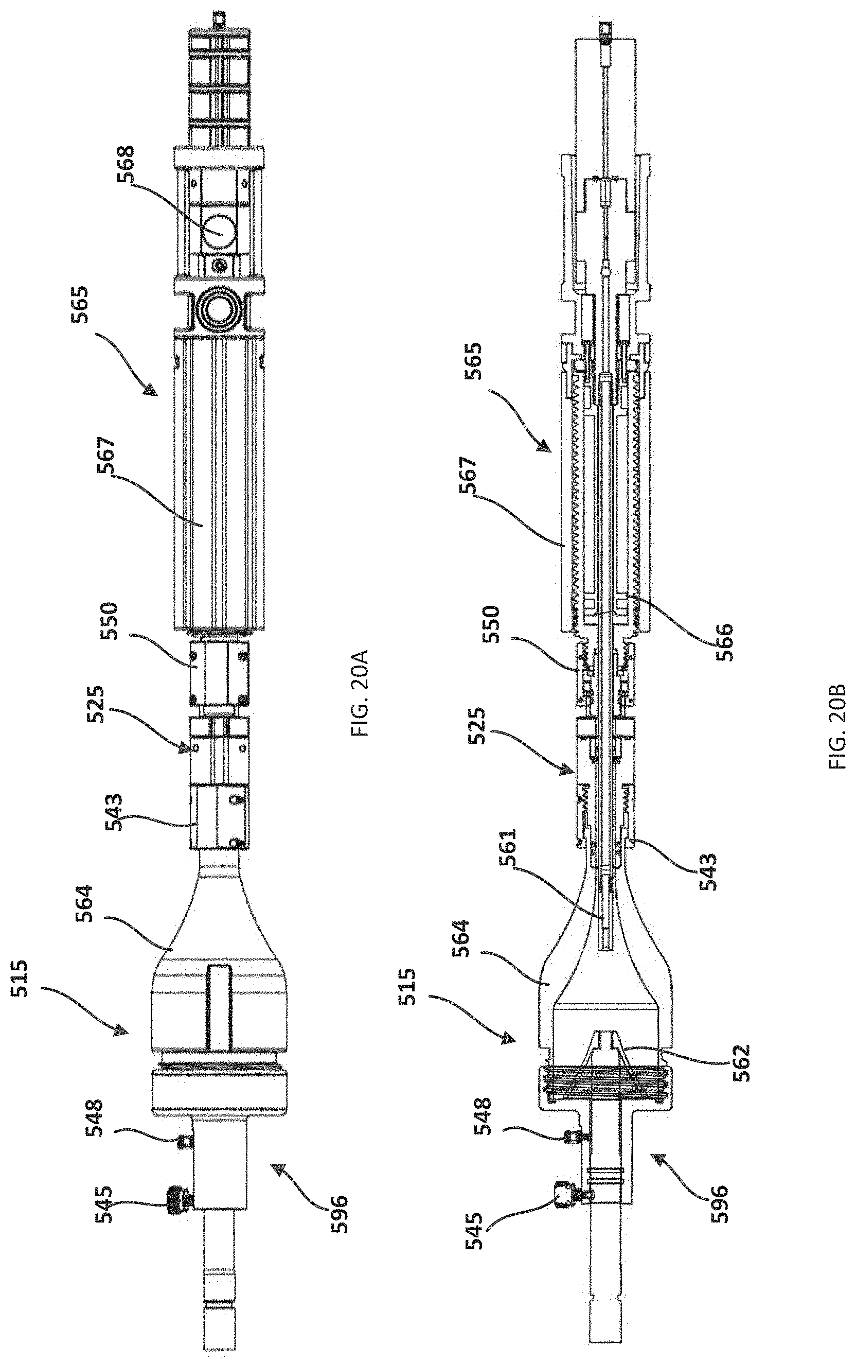
D00020

D00021

D00022

D00023

D00024

D00025

D00026

D00027

D00028

D00029
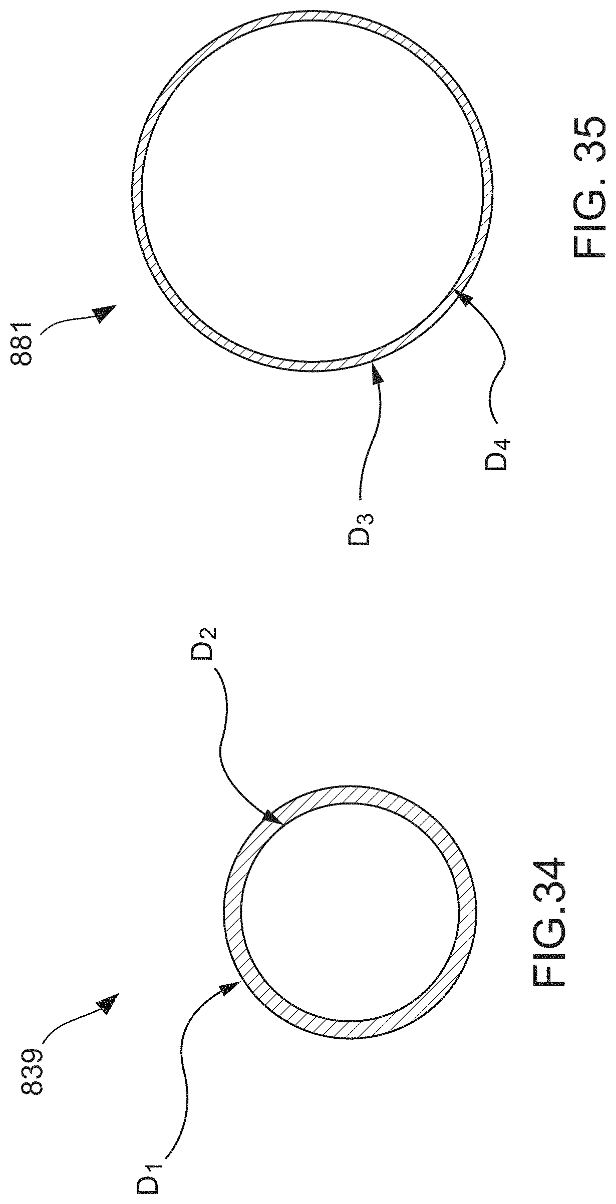
D00030
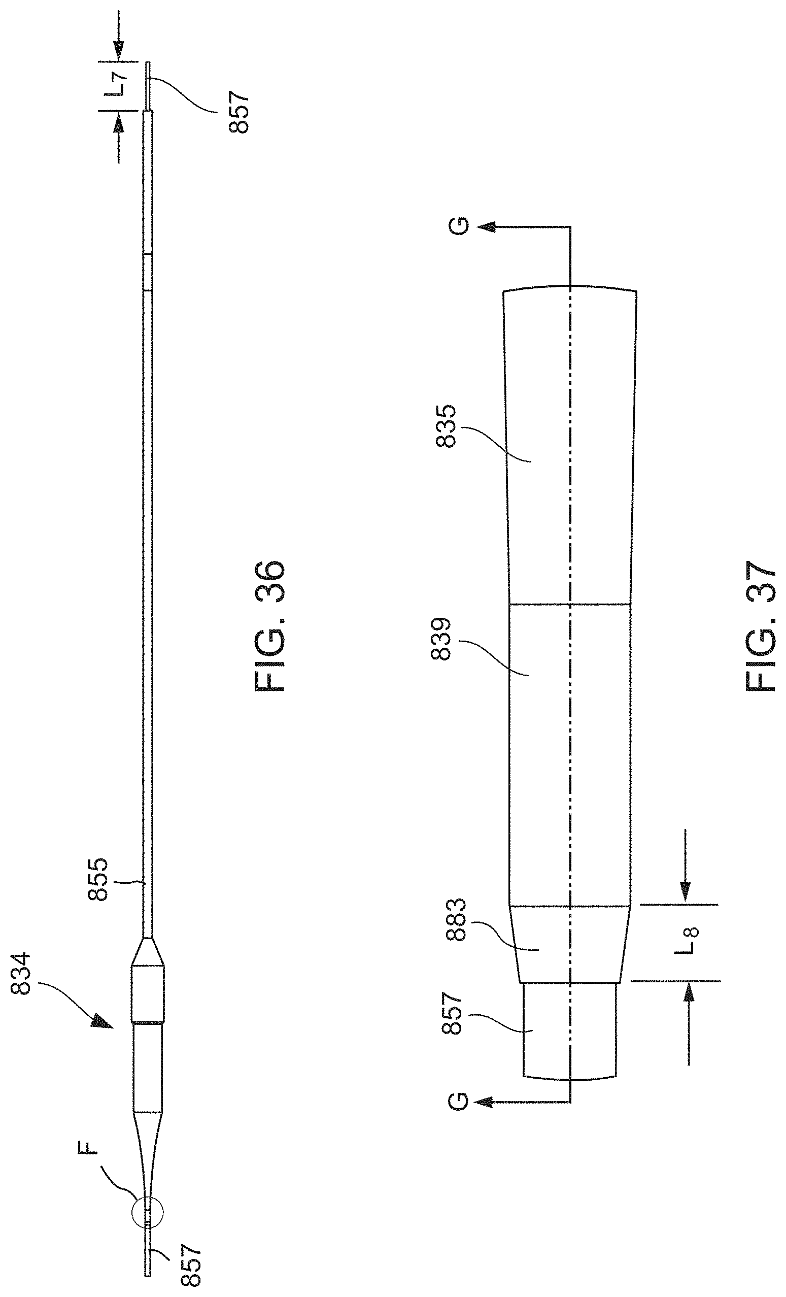
D00031

D00032

D00033

D00034
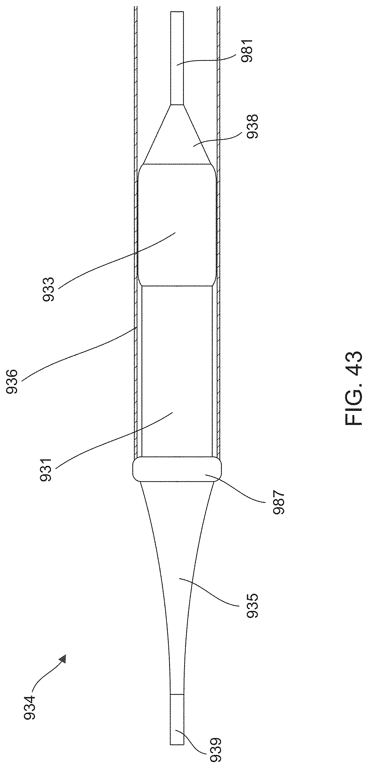
D00035

D00036

D00037

D00038

D00039

D00040

D00041

D00042

D00043

D00044

D00045

D00046

XML
uspto.report is an independent third-party trademark research tool that is not affiliated, endorsed, or sponsored by the United States Patent and Trademark Office (USPTO) or any other governmental organization. The information provided by uspto.report is based on publicly available data at the time of writing and is intended for informational purposes only.
While we strive to provide accurate and up-to-date information, we do not guarantee the accuracy, completeness, reliability, or suitability of the information displayed on this site. The use of this site is at your own risk. Any reliance you place on such information is therefore strictly at your own risk.
All official trademark data, including owner information, should be verified by visiting the official USPTO website at www.uspto.gov. This site is not intended to replace professional legal advice and should not be used as a substitute for consulting with a legal professional who is knowledgeable about trademark law.