Modular FACTS devices with external fault current protection
Inam , et al.
U.S. patent number 10,666,038 [Application Number 15/694,605] was granted by the patent office on 2020-05-26 for modular facts devices with external fault current protection. This patent grant is currently assigned to Smart Wires Inc.. The grantee listed for this patent is Smart Wires Inc.. Invention is credited to Debrup Das, Haroon Inam, Amrit Iyer.


| United States Patent | 10,666,038 |
| Inam , et al. | May 26, 2020 |
Modular FACTS devices with external fault current protection
Abstract
Flexible AC transmission system (FACTS) enabling distributed controls is a requirement for power transmission and distribution, to improve line balancing and distribution efficiency. These FACTS devices are electronic circuits that vary in the type of services they provide. All FACTS devices have internal circuitry to handle fault currents. Most of these circuits are unique in design for each manufacturer, which make these FACTS devices non-modular, non-interchangeable, expensive and heavy. One of the most versatile FACTS device is the static synchronous series compensator (SSSC), which is used to inject impedance into the transmission lines to change the power flow characteristics. The addition of integrated fault current handling circuitry makes the SSSC and similar FACTS devices unwieldy, heavy, and not a viable solution for distributed control. What is disclosed are modifications to FACTS devices that move the fault current protection external to the FACTS device and make them modular and re-usable.
| Inventors: | Inam; Haroon (San Jose, CA), Das; Debrup (Union City, CA), Iyer; Amrit (Oakland, CA) | ||||||||||
|---|---|---|---|---|---|---|---|---|---|---|---|
| Applicant: |
|
||||||||||
| Assignee: | Smart Wires Inc. (Union City,
CA) |
||||||||||
| Family ID: | 64739232 | ||||||||||
| Appl. No.: | 15/694,605 | ||||||||||
| Filed: | September 1, 2017 |
Prior Publication Data
| Document Identifier | Publication Date | |
|---|---|---|
| US 20190006835 A1 | Jan 3, 2019 | |
Related U.S. Patent Documents
| Application Number | Filing Date | Patent Number | Issue Date | ||
|---|---|---|---|---|---|
| 62527873 | Jun 30, 2017 | ||||
| Current U.S. Class: | 1/1 |
| Current CPC Class: | H02H 3/162 (20130101); H02H 9/041 (20130101); H02H 7/16 (20130101); H02J 3/06 (20130101); H02J 3/18 (20130101); H02J 3/1807 (20130101); H02H 9/005 (20130101); H02H 7/26 (20130101); H02H 9/06 (20130101) |
| Current International Class: | H02H 3/16 (20060101); H02H 9/04 (20060101); H02H 7/16 (20060101); H02J 3/18 (20060101); H02J 3/06 (20060101); H02H 9/06 (20060101); H02H 7/26 (20060101) |
References Cited [Referenced By]
U.S. Patent Documents
| 2237812 | April 1941 | De Blieux |
| 2551841 | May 1951 | Kepple et al. |
| 3556310 | January 1971 | Loukotsky |
| 3704001 | November 1972 | Sloop |
| 3750992 | August 1973 | Johnson |
| 3913003 | October 1975 | Felkel |
| 4025824 | May 1977 | Cheatham |
| 4057736 | November 1977 | Jeppson |
| 4103853 | August 1978 | Bannan |
| 4164345 | August 1979 | Arnold et al. |
| 4167670 | September 1979 | Ingold |
| 4188536 | February 1980 | DallaPiazza |
| 4200899 | April 1980 | Volman et al. |
| 4277639 | July 1981 | Olsson |
| 4286207 | August 1981 | Spreadbury et al. |
| 4293902 | October 1981 | White |
| 4322817 | March 1982 | Kuster |
| 4323722 | April 1982 | Winkelman |
| 4355351 | October 1982 | Schwarz |
| 4367512 | January 1983 | Fujita |
| 4514950 | May 1985 | Goodson, Jr. |
| 4562360 | December 1985 | Fujimoto |
| 4577826 | March 1986 | Bergstrom et al. |
| 4683461 | July 1987 | Torre |
| 4710850 | December 1987 | Jahn et al. |
| 4821138 | April 1989 | Nakano et al. |
| 4823250 | April 1989 | Kolecki et al. |
| 4903927 | February 1990 | Farmer |
| 4908569 | March 1990 | Fest |
| 5006846 | April 1991 | Granville et al. |
| 5023768 | June 1991 | Collier |
| 5032738 | July 1991 | Vithayathil |
| 5193774 | March 1993 | Rogers |
| 5270913 | December 1993 | Limpaecher |
| 5461300 | October 1995 | Kappenman |
| 5469044 | November 1995 | Gyugyi et al. |
| 5513061 | April 1996 | Gelbien et al. |
| 5610501 | March 1997 | Nelson et al. |
| 5648888 | July 1997 | Le Francois et al. |
| 5844462 | December 1998 | Rapoport et al. |
| 5875235 | February 1999 | Mohajeri |
| 5884886 | March 1999 | Hageli |
| 5886888 | March 1999 | Akamatsu et al. |
| 5892351 | April 1999 | Faulk |
| 5917779 | June 1999 | Ralson et al. |
| 5986617 | November 1999 | McLellan |
| 6061259 | May 2000 | DeMichele |
| 6075349 | June 2000 | Okayama |
| 6088249 | July 2000 | Adamson |
| 6134105 | October 2000 | Lueker |
| 6147581 | November 2000 | Rancourt et al. |
| 6198257 | March 2001 | Belehradek et al. |
| 6215653 | April 2001 | Cochran et al. |
| 6233137 | May 2001 | Kolos et al. |
| 6296065 | October 2001 | Carrier |
| 6335613 | January 2002 | Sen et al. |
| 6340851 | January 2002 | Rinaldi et al. |
| 6356467 | March 2002 | Belehradek, Jr. |
| 6397156 | May 2002 | Bachmann |
| 6460626 | October 2002 | Carrier |
| 6486569 | November 2002 | Couture |
| 6675912 | January 2004 | Carrier |
| 6727604 | April 2004 | Couture |
| 6831377 | December 2004 | Yampolsky et al. |
| 6895373 | May 2005 | Garcia et al. |
| 6914195 | July 2005 | Archambault et al. |
| 7090176 | August 2006 | Chavot et al. |
| 7091703 | August 2006 | Folts et al. |
| 7105952 | September 2006 | Divan et al. |
| 7193338 | March 2007 | Ghali |
| 7352564 | April 2008 | Courtney |
| 7440300 | October 2008 | Konishi et al. |
| 7453710 | November 2008 | Baurle et al. |
| 7460931 | December 2008 | Jacobson |
| 7642757 | January 2010 | Yoon et al. |
| 7688043 | March 2010 | Toki et al. |
| 7729147 | June 2010 | Wong et al. |
| 7834736 | November 2010 | Johnson et al. |
| 7835128 | November 2010 | Divan et al. |
| 7932621 | April 2011 | Spellman |
| 8019484 | September 2011 | Korba et al. |
| 8189351 | May 2012 | Chung et al. |
| 8249836 | August 2012 | Yoon et al. |
| 8270558 | September 2012 | Dielissen |
| 8310099 | November 2012 | Engel et al. |
| 8395916 | March 2013 | Harrison |
| 8401709 | March 2013 | Cherian et al. |
| 8441778 | May 2013 | Ashmore |
| 8497592 | July 2013 | Jones |
| 8680720 | March 2014 | Schauder et al. |
| 8681479 | March 2014 | Englert et al. |
| 8767427 | July 2014 | Wallmeier |
| 8816527 | August 2014 | Ramsay et al. |
| 8825218 | September 2014 | Cherian et al. |
| 8867244 | October 2014 | Trainer et al. |
| 8872366 | October 2014 | Campion et al. |
| 8890373 | November 2014 | Savolainen et al. |
| 8896988 | November 2014 | Subbaiahthever et al. |
| 8922038 | December 2014 | Bywaters et al. |
| 8957752 | February 2015 | Sharma et al. |
| 8996183 | March 2015 | Forbes, Jr. |
| 9065345 | June 2015 | Rigbers et al. |
| 9099893 | August 2015 | Schmiegel et al. |
| 9124100 | September 2015 | Ukai et al. |
| 9124138 | September 2015 | Mori et al. |
| 9130458 | September 2015 | Crookes et al. |
| 9172246 | October 2015 | Ramsay et al. |
| 9178456 | November 2015 | Smith et al. |
| 9185000 | November 2015 | Mabilleau et al. |
| 9207698 | December 2015 | Forbes, Jr. |
| 9217762 | December 2015 | Kreikebaum et al. |
| 9246325 | January 2016 | Coca Figuerola et al. |
| 9325173 | April 2016 | Varma et al. |
| 9331482 | May 2016 | Huang |
| 9332602 | May 2016 | Roberts et al. |
| 9473028 | October 2016 | Hoyt |
| 9563218 | February 2017 | Hall et al. |
| 9659114 | May 2017 | He et al. |
| 9735702 | August 2017 | Hu et al. |
| 9843176 | December 2017 | Gibson et al. |
| 2002/0005668 | January 2002 | Couture |
| 2002/0042696 | April 2002 | Garcia et al. |
| 2003/0006652 | January 2003 | Couture |
| 2003/0098768 | May 2003 | Hoffmann et al. |
| 2004/0153215 | August 2004 | Kearney et al. |
| 2004/0217836 | November 2004 | Archambault et al. |
| 2005/0052801 | March 2005 | Ghali |
| 2005/0073200 | April 2005 | Divan et al. |
| 2005/0194944 | September 2005 | Folts et al. |
| 2005/0205726 | September 2005 | Chavot et al. |
| 2006/0085097 | April 2006 | Courtney |
| 2007/0135972 | June 2007 | Jacobson |
| 2007/0250217 | October 2007 | Yoon et al. |
| 2008/0103737 | May 2008 | Yoon et al. |
| 2008/0157728 | July 2008 | Toki et al. |
| 2008/0177425 | July 2008 | Korba et al. |
| 2008/0205088 | August 2008 | Chung et al. |
| 2008/0278976 | November 2008 | Schneider et al. |
| 2008/0310069 | December 2008 | Divan et al. |
| 2009/0243876 | October 2009 | Lilien et al. |
| 2009/0281679 | November 2009 | Taft et al. |
| 2010/0014322 | January 2010 | Harrison |
| 2010/0026275 | February 2010 | Walton |
| 2010/0094477 | April 2010 | Berggren |
| 2010/0177450 | July 2010 | Holcomb et al. |
| 2010/0213765 | August 2010 | Engel et al. |
| 2010/0302744 | December 2010 | Englert et al. |
| 2011/0060474 | March 2011 | Schmiegel et al. |
| 2011/0095162 | April 2011 | Parduhn et al. |
| 2011/0106321 | May 2011 | Cherian et al. |
| 2011/0172837 | July 2011 | Forbes, Jr. |
| 2012/0105023 | May 2012 | Schauder et al. |
| 2012/0146335 | June 2012 | Bywaters et al. |
| 2012/0205981 | August 2012 | Varma et al. |
| 2012/0242150 | September 2012 | Ukai et al. |
| 2012/0255920 | October 2012 | Shaw et al. |
| 2012/0293920 | November 2012 | Subbaiahthever et al. |
| 2013/0002032 | January 2013 | Mori et al. |
| 2013/0033103 | February 2013 | McJunkin et al. |
| 2013/0044407 | February 2013 | Byeon et al. |
| 2013/0094264 | April 2013 | Crookes et al. |
| 2013/0128636 | May 2013 | Trainer et al. |
| 2013/0166085 | June 2013 | Cherian et al. |
| 2013/0169044 | July 2013 | Stinessen et al. |
| 2013/0182355 | July 2013 | Coca Figuerola et al. |
| 2013/0184894 | July 2013 | Sakuma et al. |
| 2013/0200617 | August 2013 | Smith et al. |
| 2013/0249321 | September 2013 | Gao et al. |
| 2013/0277082 | October 2013 | Hyde et al. |
| 2013/0345888 | December 2013 | Forbes, Jr. |
| 2014/0008982 | January 2014 | Powell et al. |
| 2014/0025217 | January 2014 | Jin et al. |
| 2014/0032000 | January 2014 | Chandrashekhara et al. |
| 2014/0111297 | April 2014 | Earhart et al. |
| 2014/0129195 | May 2014 | He et al. |
| 2014/0132229 | May 2014 | Huang |
| 2014/0153383 | June 2014 | Mabilleau et al. |
| 2014/0188689 | July 2014 | Kalsi et al. |
| 2014/0203640 | July 2014 | Stinessen |
| 2014/0210213 | July 2014 | Campion et al. |
| 2014/0246914 | September 2014 | Chopra et al. |
| 2014/0247554 | September 2014 | Sharma et al. |
| 2014/0266288 | September 2014 | Trabacchin et al. |
| 2014/0268458 | September 2014 | Luciani et al. |
| 2014/0312859 | October 2014 | Ramsay et al. |
| 2014/0327305 | November 2014 | Ramsay et al. |
| 2014/0347158 | November 2014 | Goeke et al. |
| 2015/0012146 | January 2015 | Cherian et al. |
| 2015/0029764 | January 2015 | Peng |
| 2015/0051744 | February 2015 | Mitra |
| 2015/0184415 | July 2015 | Bushore |
| 2015/0226772 | August 2015 | Kreikebaum et al. |
| 2015/0236509 | August 2015 | Divan |
| 2015/0244307 | August 2015 | Cameron |
| 2015/0270689 | September 2015 | Gibson et al. |
| 2016/0036231 | February 2016 | Ramsay et al. |
| 2016/0036341 | February 2016 | Jang et al. |
| 2017/0163036 | June 2017 | Munguia et al. |
| 2017/0169928 | June 2017 | Carrow et al. |
| 2017/0170660 | June 2017 | Hu et al. |
| 2017/0237255 | August 2017 | Inam et al. |
| 660094 | Mar 1987 | CH | |||
| 103256337 | Aug 2013 | CN | |||
| 203668968 | Jun 2014 | CN | |||
| 2002-199563 | Jul 2002 | JP | |||
| 2005-045888 | Feb 2005 | JP | |||
| 2015-086692 | May 2015 | JP | |||
| 10-1053514 | Aug 2011 | KR | |||
| 2005/067117 | Jul 2005 | WO | |||
| WO-2008/082820 | Jul 2008 | WO | |||
| WO-2014/035881 | Mar 2014 | WO | |||
| WO-2014/074956 | May 2014 | WO | |||
| WO-2014/099876 | Jun 2014 | WO | |||
| WO-2015/074538 | May 2015 | WO | |||
| WO-2015/119789 | Aug 2015 | WO | |||
Other References
|
Amin, S. M. et al., "Toward a Smart Grid: Power Delivery for the 21st Century", IEEE power & energy magazine, vol. 3, No. 5, Sep./Oct. 2005, pp. 34-41. cited by applicant . Angeladas, Emmanouil , "High Voltage Substations Overview (part 1)", Siemens, Jan. 24, 2013, pp. 1-8. cited by applicant . Aquino-Lugo, Angel A. , "Distributed and Decentralized Control of the Power Grid", Ph.D. Dissertation, University of Illinois at Urbana-Champaign, 2010, 172 pp. total. cited by applicant . Dash, P. K. et al., "Digital Protection of Power Transmission Lines in the Presence of Series Connected FACTS Devices", IEEE Power Engineering Society Winter Meeting, 2000, pp. 1967-1972. cited by applicant . Divan, D. M. , "Nondissipative Switched Networks for High-Power Applications", Electronics Letters, vol. 20, No. 7, Mar. 29, 1984, pp. 277-279. cited by applicant . Funato, Hirohito et al., "Realization of Negative Inductance Using Variable Active-Passive Reactance (VAPAR)", IEEE Transactions on Power Electronics, vol. 12, No. 4, Jul. 1997, pp. 589-596. cited by applicant . Gyugyi, Laszlo et al., "Status Synchronous Series Compensator: A Solid-State Approach to the Series Compensation of Transmission Lines", IEEE Transactions on Power Delivery, vol. 12, No. 1, Jan. 1997, pp. 406-417. cited by applicant . Gyugyi, Laszlo et al., "The Interline Power Flow Controller Concept: A New Approach to Power Flow Management in Transmission Systems", IEEE Transactions on Power Delivery, vol. 14, No. 3, Jul. 1999, pp. 1115-1123. cited by applicant . Kavitha, M. et al., "Integration of FACTS into Energy Storage Systems for Future Power Systems Applications", International Journal of Advanced Research in Electrical, Electronics and Instrumentation Engineering, vol. 2, Issue 2, Feb. 2013, pp. 800-810. cited by applicant . Kumbhar, Mahesh M. et al., "Smart Grid: Advanced Electricity Distribution Network", IOSR Journal of Engineering (IOSRJEN), vol. 2, Issue 6, Jun. 2012, pp. 23-29. cited by applicant . Lambert, Frank C. , "Power Flow Control", ISGT Europe, 2014, Istanbul, Turkey, Oct. 13, 2014, pp. 1-15. cited by applicant . Lehmkoster, Carsten , "Security Constrained Optimal Power Flow for an Economical Operation of FACTS-Devices in Liberalized Energy Markets", IEEE Transactions on Power Delivery, vol. 17, No. 2, Apr. 2002, pp. 603-608. cited by applicant . Mali, Bhairavanath N. et al., "Performance Study of Transmission Line Ferranti Effect and Fault Simulation Model Using MATLAB", International Journal of Innovative Research in Electrical, Electronics, Instrumentation and Control Engineering, vol. 4, Issue 4, Apr. 2016, pp. 49-52. cited by applicant . Mutale, Joseph et al., "Transmission Network Reinforcement Versus FACTS: An Economic Assessment", IEEE Transactions on Power Systems, vol. 15, No. 3, Aug. 2000, pp. 961-967. cited by applicant . Ramchurn, Sarvapali D. et al., "Putting the `Smarts` into the Smart Grid: A Grand Challenge for Artificial Intelligence", Communications of the ACM, vol. 55, No. 4, Apr. 2012, pp. 86-97. cited by applicant . Reddy, D. M. et al., "FACTS Controllers Implementation in Energy Storage Systems for Advanced Power Electronic Applications--A Solution", American Journal of Sustainable Cities and Society, Issue 2, vol. 1, Jan. 2013, pp. 36-63. cited by applicant . Renz, B. A. et al., "AEP Unified Power Flow Controller Performance", IEEE Transactions on Power Delivery, vol. 14, No. 4, Oct. 1999, pp. 1374-1381. cited by applicant . Ribeiro, P. et al., "Energy Storage Systems", Chapters 1-2.4 of Section entitled "Energy Storage Systems" in Electrical Engineering--vol. III, edited by Kit Po Wong, Encyclopedia of Life Support Systems (EOLSS) Publications, Dec. 13, 2009, 11 pp. total. cited by applicant . Schauder, C. D. et al., "Operation of the Unified Power Flow Controller (UPFC) Under Practical Constraints", IEEE Transactions on Power Delivery, vol. 13, No. 2, Apr. 1998, pp. 630-639. cited by applicant . Siemens SAS, ,"Portable Power Solutions, "Plug and play" High Voltage E-Houses, skids and mobile high voltage substations up to 420 kV", Nov. 2015, 8 pp. total. cited by applicant . Swain, S. C. et al., "Design of Static Synchronous Series Compensator Based Damping Controller Employing Real Coded Genetic Algorithm", International Journal of Electrical, Computer, Energetic, Electronic and Communication Engineering, vol. 5, No. 3, 2011, pp. 399-407. cited by applicant . Xue, Yiyan et al., "Charging Current in Long Lines and High-Voltage Cables--Protection Application Considerations", 67th Annual Georgia Tech Protective Relaying Conference, Atlanta, Georgia, May 8-10, 2013, pp. 1-17. cited by applicant . "International Search Report and Written Opinion of the International Searching Authority dated Aug. 14, 2018; International Application No. PCT/US2018/034476", Aug. 14, 2018. cited by applicant . Albasri, Fadhel A. et al., "Performance Comparison of Distance Protection Schemes for Shung-FACTS Compensated Transmission Lines", IEEE Transactions on Power Delivery, vol. 22, No. 4, Oct. 2007, pp. 2116-2125. cited by applicant . Bhaskar, M. A. et al., "Impact of FACTS devices on distance protection in Transmission System", 2014 IEEE National Conference on Emerging Trends in New & Renewable Energy Sources and Energy Management (NCET NRES EM), Dec. 16, 2014, pp. 52-58. cited by applicant . Samantaray, S. R. , "A Data-Mining Model for Protection of FACTS-Based Transmission Line", IEEE Transactions on Power Delivery, vol. 28, No. 2, Apr. 2013, pp. 612-618. cited by applicant . "Extended European Search Report dated Sep. 9, 2019; European Patent Application No. 19153095.5", Sep. 9, 2019. cited by applicant. |
Primary Examiner: Bauer; Scott
Attorney, Agent or Firm: Womble Bond Dickinson (US) LLP
Parent Case Text
CROSS-REFERENCE TO RELATED APPLICATIONS
This application claims the benefit of U.S. Provisional Patent Application No. 62/527,873 filed Jun. 30, 2017.
Claims
What is claimed is:
1. A method of providing distributed controls for a power transmission and distribution system comprising: providing flexible alternating current transmission systems (FACTS) devices, each without fault current protection; providing fault current protection modules as modules not containing a FACTS device; providing a plurality of FACTS devices on a power transmission line; and coupling a fault current module to the transmission line so that the fault current module is coupled in parallel with all FACTS devices in the plurality of FACTS devices; wherein the FACTS devices are connected in parallel, or some of the FACTS devices are connected in series and some of the FACTS devices are connected in parallel.
2. The method of claim 1 wherein the FACTS devices comprise at least one static synchronous series compensator.
3. The method of claim 1 wherein the FACTS devices comprise at least one thyristor controlled series compensator.
4. The method of claim 1 wherein the FACTS devices and the fault current protection module are hung on the transmission line.
5. The method of claim 1 wherein the fault current protection module is separately supported.
6. The method of claim 1 wherein the FACTS devices and the fault current protection module are located in a substation.
7. The method of claim 1 wherein the fault current protection module includes a bypass breaker for short circuits and ground fault conditions.
8. The method of claim 7 wherein the fault current protection module further includes a metal oxide varistor for short duration faults, surges, and transient events.
9. The method of claim 1 wherein the fault current protection module further includes a recloser switch for reset when the faults are removed.
10. The method of claim 9 wherein the recloser switch also functionally isolates a respective group of FACTS devices by removing transmission line current from the respective group of FACTS devices.
11. The method of claim 1 wherein the transmission line includes a first breaker between a first bus and the FACTS devices, and a second breaker between the FACTS devices and a second bus on the transmission line to isolate the transmission line section between the first and second breakers from the rest of the transmission system.
12. A method of providing distributed controls for a power transmission and distribution system comprising: providing flexible alternating current transmission systems (FACTS) devices, each without fault current protection; providing fault current protection modules as modules not containing a FACTS device; providing a plurality of FACTS devices on a power transmission line; and coupling a fault current module to the transmission line so that the fault current module is coupled in parallel with all FACTS devices in the plurality of FACTS devices; wherein the transmission line includes a first breaker between a first bus and the FACTS devices, and a second breaker between the FACTS devices and a second bus on the transmission line to isolate the transmission line section between the first and second breakers from the rest of the transmission system; wherein the transmission line further includes additional breakers connected to ground to discharge the FACTS devices and adjoining section of the transmission line when the transmission line section is disconnected from the transmission system by the first and second breakers.
13. A system for providing distributed controls for a power transmission and distribution system comprising; a plurality of flexible alternating current transmission systems (FACTS) devices, each without fault current protection, that are enabled as FACTS modules for distribution over the power transmission and distribution system; at least a fault current protection module that is not part of a FACTS module; wherein the FACTS modules are coupled to a transmission line of the power transmission and distribution system as at least a group of FACTS modules; and the at least a fault current protection module is connected in parallel across each of the at least a group of FACTS modules to provide fault current protection; wherein the at least a group of FACTS modules are enabled as a parallel connected group of FACTS modules coupled to the transmission line, or the at least a group of FACTS modules are enabled as a plurality of serial strings of FACTS modules connected in parallel coupled to the transmission line.
14. The system of claim 13, wherein each of the at least a group of FACTS modules having the at least a fault current protection module connected in parallel are coupled to the power transmission line by a first bus having a first circuit breaker at one end and a second bus having a second circuit breaker at the other end; wherein the circuit breakers are enabled to isolate a segment of the transmission line between the first circuit breaker and the second circuit breaker from the transmission system.
Description
BACKGROUND OF THE INVENTION
1. Field of the Invention
The present invention relates to systems and methods for flexible AC transmission systems (FACTS) and specifically to use of distributed power transmission and distribution control by static synchronous series compensators and other FACTs devices.
2. Prior Art
FACTS based distributed control of transmission lines and connected distributed generation capabilities and loads have become very critical for improving the efficiency of the power grid. In flexible AC transmission systems (FACTS), power flow control devices vary in the type of services they can provide. Devices operate in either series or shunt modes, and are highly complex and sophisticated pieces of machinery that require long planning cycles and preparation before installation.
Many of the FACTS devices use high voltage semiconductor-based power electronic converters to control the required parameters, such as line current, bus voltage, and more. Although converter-based FACTS devices provide more granular and faster control than electro-mechanical devices such as Phase Shifting Transformers, the former have significant limitations in fault-handling capability. The cost and complexity of the fault-handling strategy and circuit design in a FACTS device is one of the significant limitations and is considered one of the main deterrents for large-scale adoption of the FACTS technology.
Furthermore, most FACTS devices today are custom-built for specific applications, thus, no plug-and-play solution exists today. The lack of a solution is due to the unique design of the fault handling capability designed and implemented by individual suppliers of the FACTS systems and modules.
During a typical fault on the power grid very high currents appear on the transmission lines of the grid. These fault conditions can be short lived, such as those due to a lightning strike or they can be extended such as those due to ground shorts. Since the electronic components and thyristor used in todays' FACTS devices are prone to failure when such currents are impressed on them, these conditions must be handled by the fault protection circuitry. The high, short-duration faults are generally diverted away from sensitive semi-conductor switches (like IGBTs) using fast acting, more robust switches such as SCRs, electro-mechanical contactors, etc. In additions the circuits may also use metal oxide varistors (MOVs) to limit voltage rise. MOVs have a resistance value that reduces with the voltage applied across it.
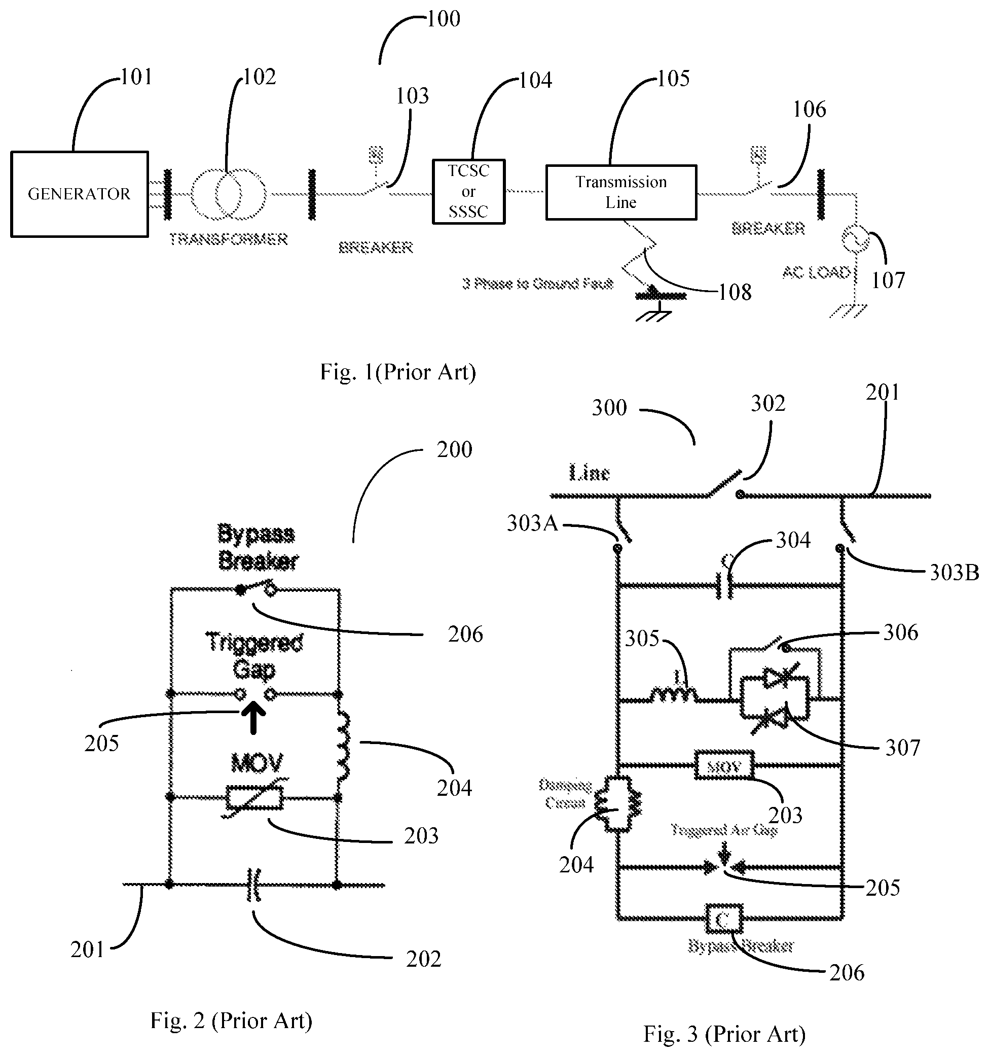
FIG. 1 shows a prior art implementation 100 of a thyristor controlled Series compensator (TCSC) or a synchronous static series compensator (SSSC) 104 that includes the fault current protection as part of the power grid system 100. The power system comprises: the generator 101, the transformer 102, for stepping up the voltage for transmission over the transmission line 105. The circuit breaker (CB) 103 is used to isolate the generator 101 from the transmission line 105 and any FACTS devices like TCSC or SSSC 104 in case of ground short 108. A second breaker 106 is used to isolate the power grid from the load 107. During regular operation, the TCSC or the SSSC 104 provide the capability for the line to be efficiently used for transfer of power.
FIG. 2 is a prior art example of the series capacitive compensation for the inductance of the power lines. As can be seen the protection circuit associated with the capacitor 202 in series with the power line 201 comprise the MOV bank 203 and a triggered gap 205, which may be a vacuum bottle, in series with an inductance 204 used to limit the current through the vacuum bottle or in the case of longer time periods the bypass CB 206.
FIG. 3 is a prior art example of a single TCSC unit 307 with the associated fault current protection circuits. The TCSC 307 with the re-closer switch 306, and in combination with the inductor `L` 305 in parallel with the capacitor `C` 304 is able to inject both capacitive or inductive impedances on the power line 201 based on the firing of the thyristors, the control being provided by the firing angle and duration. The protection circuitry includes the MOV 203 stack, the triggered air/vacuum gap 205, and the bypass breaker 206. The triggered air gap 205 and the bypass breaker have the damping circuit 204 to reduce oscillations and provide a current limit. In addition to the fault current protection the FIG. 3 also shows the circuit breakers 303 A and 303 B which allow the TCSC module to be disconnected from the line 201 and a re-closer breaker 302 for reconnecting the TCSC when a fault is repaired.
These prior art FACTS based power flow control modules show the control circuits with the fault protection associated with it. The fault protection makes the control units large and unwieldy. It is hence only efficient to have the power flow control modules in substations and not usable effectively in distributed control applications.
It will be ideal if the fault handling capability can be removed from inside the FACTS systems and modules to an external protection scheme. The individual FACTS modules and systems then become modular and capable of plug and play. In addition the modular FACTS devices are lighter and smaller and can thus be useable in distributed applications on the grid.
BRIEF DESCRIPTION OF THE DRAWINGS
The drawings are made to point out and distinguish the invention from the prior art. The objects, features and advantages of the invention are detailed in the description taken together with the drawings.
FIG. 1 is a prior art system block diagram 100 of thyristor controlled series compensator (TCSC) with breaker protections as part of the power grid system.
FIG. 2 is a prior art block diagram 200 of a series capacitor bank including the fault current protection components.
FIG. 3 is an exemplary prior art block diagram 300 showing the internal components including fault protection components of the TCSC of FIG. 1. (Prior Art)
FIG. 4 is an exemplary block diagram 400 of TCSC without fault current protection and its block representation 401 as per an embodiment of the current invention.
FIG. 5 is an exemplary block diagram 500 of an SSSC without fault current protection and its block representation 501 as per an embodiment of the current invention.
FIG. 6 is an exemplary block diagram 600 of an implementation of the fault current protection module and its single block representation 601 as per an embodiment of the present invention.
FIG. 7 is an exemplary power grid system block diagram 700 with TCSC 401 or SSSC 501 with external Fault current protection 601 and bypass and ground isolation protections.
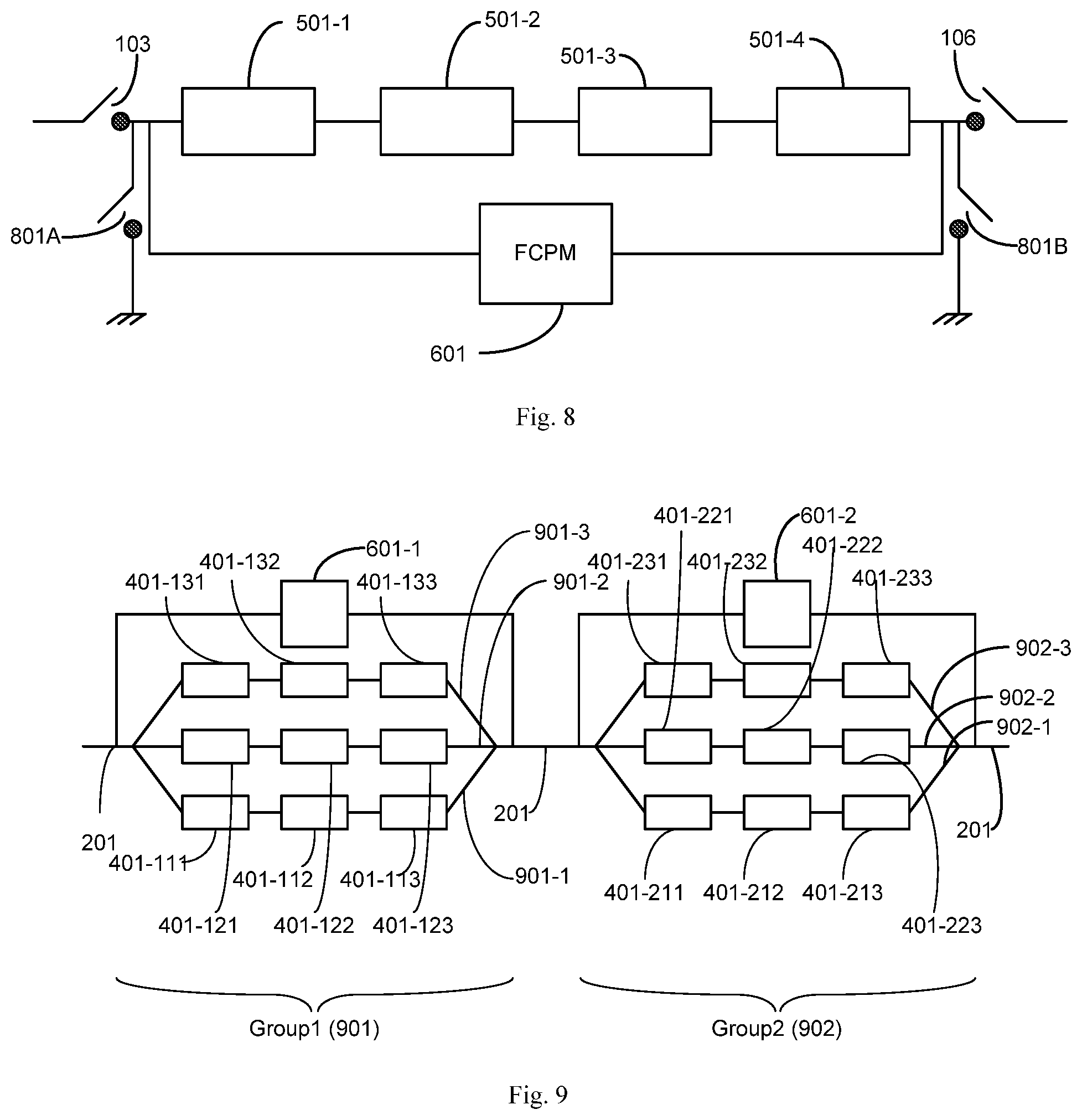
FIG. 8 is an exemplary diagram showing multiple SSSCs 501s deployed in series being protected by an external fault current protection module 601, the SSSCs further being enabled for isolation and ground connection using breakers.
FIG. 9 is an exemplary deployment of two groups of TCSCs in series parallel configuration with external fault current protection.
DETAILED DESCRIPTION OF THE PREFERRED EMBODIMENTS
The primary change to the FACTS devices is moving the unit-level fault protection module external to the FACTS device. This provides:
Substantial reduction in volume and weight of the FACTS devices allowing them to be used in (1) distributed applications; (2) applications where a plurality of FACTS devices need to be configured and used as a group. In that regard, the reduction in volume allows heat generated within the FACTS devices to more readily pass out.
The system reliability is improved due to reduction in the number of modules/components used, that result in reducing the number of failure points or nodes within the implemented modules and sub-systems.
The removal of custom designed fault protection modules enables standardization of the FACTS modules for use in distributed applications requiring lower cost.
Flexible AC transmission system (FACTS) enabling distributed controls is a requirement for power transmission and distribution, to improve line balancing and distribution efficiency. These FACTS devices are electronic circuits that vary in the type of services they provide. All FACTS devices have internal circuitry to handle fault currents. Most of these circuits are unique in design for each manufacturer, which make these FACTS devices non-modular, non-interchangeable, expensive and heavy. One of the most versatile FACTS device, the static synchronous series compensator (SSSC) is used to inject impedance into the transmission lines to change the power flow characteristics. The addition of integrated fault current handling circuitry makes the SSSCs and similar FACTS devices unwieldy, heavier and not viable as a solution for distributed control. What is disclosed are modifications to FACTS devices that move the fault current protection external to the FACTS device and make them modular and re-usable.
FIG. 4 shows a TCSC module 400 wherein the fault current protection circuit has been removed. The TCSC module 400 is connected in series with power line 201. Module 400 comprise two branches in parallel, one branch being the capacitor `C` 304 and the second branch being the inductor `L` 305 in series with the thyristor switching unit 307. A recloser switch 306 is connected in parallel with the thyristor switching unit 307 to shunt the unit when reclosure is necessary. By controlling the firing frequency and firing angle of the thyristors in the thyristor switching unit 307 the module is able to impress either an inductive or a capacitive impedance on the power line 201 to control the power flow on the line 201. The control instructions and coordination of the TCSC 400 in distributed situations mandate coordinated action with other TCSC modules 400 and any fault protection units external to the TCSC module 400. A dedicated communication module 410 communicably links the TCSC module 400 to other FACTS modules, external fault protection units and control and coordination facility. Similar communication modules are used with all TCSC modules, SSSC modules and FCPM modules (fault current protection modules such as illustrated in FIGS. 6-9, though not shown therein so as to not obscure the points being illustrated. A representative block of the TCSC module 400 is shown as block 401.
Similar to FIG. 4, FIG. 5 shows the SSSC module 500 with the fault protection circuitry removed. The SSSC 500 is shown as being coupled to the power line 201 by an injection transformer, having a primary winding 505 in series with the line 201 and a secondary winding 502. Similar to the TCSC module 400, the SSSC module 500 contain the HV switches 301A to 307D connected across the secondary 502 of the injection transformer as well as a capacitor C 304 in parallel as shown. A dedicated communication module 510 allow the SSSC module 500 to coordinate with other FACTS control devices, external fault protection units and control and coordination facility in a manner similar to the TCSC module 400. The SSSC 500 module is represented as a block by the equivalent block 501.
FIG. 6 shows an exemplary external fault current protection module (FCPM) 600. The FCPM 600 is connected to the line 201 spanning the circuits to be protected. It comprise the MOV 203 to handle the short duration faults, surges and transients, a triggered gap 205 in series with a current limiting inductor 204 to handle longer faults, and a bypass switch 206 to handle short circuits and ground short conditions. It also has a recloser switch 302 to enable the system to be reset when the faults are removed. The exemplary external FCPM 600 is also represented by the FCPM block 601. An FCPM 601 may be hung from a transmission line or supported by a separate support, such as a separate ground based or tower support, or as a further alternative, the FCPM as well as the TCSCs and/or SSSCs may be located in a substation, such as by way of example, a substation provided specifically for that purpose.
As discussed previously, each manufacturer of the prior art FACTS device custom designed the FCPM to suit their design requirements and manufacturing capabilities. By removing the non-standardized fault current protection devices from the prior art TCSC 300 and the prior art SSSC, new modular and standardized TCSC 401 and SSSC 501 that handle the desired function are made available from all FACTS manufacturers. These standardized TCSC 401 and SSSC 501 are much smaller in size, lower in weight, and usable in a distributed fashion. Having the external FCPM 601 separate from the modular TCSC 401 and SSSC 501 makes arranging a plurality of these standardized FACTS modules in parallel or in series with a single external FCPM 601 module to handle power transfer requirements of the power grid, reducing the cost and efficiency of such implementation.
One of the challenges that arise when a plurality of the FACTS modules are connected in parallel or in series, as a group, is the need for coordinating their operation to achieve the operational goals. High speed and secure inter module, group to group and group to facility control is essential for the proper operation of the inter linked FACTS devices and the single connected fault current protection module. Secure and dedicated communication techniques including line of sight wireless communication using 60 and 80 Ghz bands, direct communication using lasers etc. The challenge also extends to the operational integration requirement for control between the plurality of FACTS devices connected. This includes decision on which of the connected devices should be active at any point in time and when the various protection devices should become active.
FIG. 7 shows an exemplary block diagram 700 of implementation of the external FCPM 601 with FACTS modules like TCSC 401 or SSSC 501 modules on a power grid. The block diagram 700 is similar to the FIG. 1 block diagram 100 and shows two sets of modular FACTS units such as TCSC 401 and SSSC 501 used instead of a single unit having the fault protection built in. Each of the modular plurality of FACTS units are protected by one FCPM 601-1.
FIG. 8 shows a block diagram 800 of one arrangement of the FACTS units such as SSSC 501-1 to 501-4 in a series connection with one external FCPM 601. Two circuit breakers 103 and 106 are shown for isolating the modular FACTS units and the faulty line section between a first bus 105A and a second bus 105B from the rest of the transmission system; in case of failure 108. Two additional ground connected breakers 801A and 801B are also provided to allow discharging of the set of FACTS modules and the section of the isolated transmission line when disconnected from the transmission system using breakers 103 and 106.
FIG. 9 shows a block diagram 900 showing an alternate way for arranging the plurality of FACTS devices such as TCSC 401 in a parallel serial connection. Each of the two groups of nine TCSC 401 devices 901 and 902 shown as example are connected in strings of three devices and arranged in three parallel interconnected strings. The devices are designated as 401-gsp; where g is the group, s is the string and p is the position of the device on the string. Hence a TCSC 401 in group 2, on the second string at second position will be 401-222 and a TCSC 401 of the 1st group in the 3rd string first position will have a designation 401-131 and so on. Each group of nine TCSC 401s are shown as being protected by a single external FCPM 601.
The organization of the groups with the capability to isolate the protected groups provide a big advantage to the serviceability of the grid system. It is hence possible if a failure occurs in the FCPM 601 module or any of the individual FACTS 401 modules, to isolate the failed module and replace the same with a similar module that is standardized and pre-tested. The selective enablement of groups of FACTS 401 devices for power flow control and serviceability without disrupting normal operations is hence fully enabled by the modular replacement capability and standardization of the FACTS 401 and FCPM 601 modules used.
The removal of the fault current protection module, by design, from each FACTS device has numerous advantages. It reduces cost by eliminating unnecessary duplication of heavy circuitry, itself very advantageous when the FACTS devices are to be hung from the transmission line. It reduces the volume (wind forces) and the cooling requirements of each FACTS device. It also allows and encourages standardization of the FACTS modules in performance and control, and similarly allows independent selection of a fault current protection module design for broad use, again standardizing their performance, communication and control requirements. Using a fault current protection module having a recloser switch such as switch 302 (FIG. 6), a protected group of FACTS devices can be functionally isolated from the respective transmission line by closing the recloser switch to remove or divert transmission line current around that group of FACTS devices, which may be useful in normal operation, and particularly useful upon a failure or excess heating of a respective FACTS device in that group.
Even though the invention disclosed is described using specific implementation, it is intended only to be exemplary and non-limiting. The practitioners of the art will be able to understand and modify the same based on new innovations and concepts, as they are made available. The invention is intended to encompass these modifications.
Thus, the present invention has a number of aspects, which aspects may be practiced alone or in various combinations or sub-combinations, as desired. Also while certain preferred embodiments of the present invention have been disclosed and described herein for purposes of exemplary illustration and not for purposes of limitation, it will be understood by those skilled in the art that various changes in form and detail may be made therein without departing from the spirit and scope of the invention.
* * * * *
D00000
D00001
D00002
D00003
D00004
XML
uspto.report is an independent third-party trademark research tool that is not affiliated, endorsed, or sponsored by the United States Patent and Trademark Office (USPTO) or any other governmental organization. The information provided by uspto.report is based on publicly available data at the time of writing and is intended for informational purposes only.
While we strive to provide accurate and up-to-date information, we do not guarantee the accuracy, completeness, reliability, or suitability of the information displayed on this site. The use of this site is at your own risk. Any reliance you place on such information is therefore strictly at your own risk.
All official trademark data, including owner information, should be verified by visiting the official USPTO website at www.uspto.gov. This site is not intended to replace professional legal advice and should not be used as a substitute for consulting with a legal professional who is knowledgeable about trademark law.