Sterile medical instrument charging device
Madan , et al.
U.S. patent number 10,660,695 [Application Number 15/212,423] was granted by the patent office on 2020-05-26 for sterile medical instrument charging device. This patent grant is currently assigned to Ethicon LLC. The grantee listed for this patent is Ehticon Endo-Surgery, LLC. Invention is credited to Jeffrey L. Aldridge, Timothy G. Dietz, Kevin D. Felder, Kevin L. Houser, Donna L. Korvick, Ashvani K. Madan, Gavin M. Monson, Sora Rhee, Michael J. Stokes, John W. Willis, Aron O. Zingman.


View All Diagrams
| United States Patent | 10,660,695 |
| Madan , et al. | May 26, 2020 |
Sterile medical instrument charging device
Abstract
A system includes a medical device and a charging device. A sterile barrier may be interposed between the medical device and the charging device. The medical device includes an integral power source and an active element. The charging device is configured to charge the integral power source. The charging device may charge the integral power source through direct contact between features of the charging device and features the medical device. The charging device may alternatively charge the integral power source wirelessly, such as through inductive coupling. The medical device may include conductive prongs that are retained by the charging device. The charging device may physically couple with the medical device via magnets. The medical device and the charging device may be provided together in a sterile package as a kit. The kit may also include a reclamation bag to facilitate reclamation of electrical components.
| Inventors: | Madan; Ashvani K. (Mason, OH), Korvick; Donna L. (Maineville, OH), Zingman; Aron O. (Cambridge, MA), Willis; John W. (Cincinnati, OH), Houser; Kevin L. (Springboro, OH), Monson; Gavin M. (Oxford, OH), Felder; Kevin D. (Cincinnati, OH), Stokes; Michael J. (Cincinnati, OH), Rhee; Sora (Pennsylvania Furnace, PA), Dietz; Timothy G. (Wayne, PA), Aldridge; Jeffrey L. (Lebanon, OH) | ||||||||||
|---|---|---|---|---|---|---|---|---|---|---|---|
| Applicant: |
|
||||||||||
| Assignee: | Ethicon LLC (Guaynabo,
PR) |
||||||||||
| Family ID: | 67148321 | ||||||||||
| Appl. No.: | 15/212,423 | ||||||||||
| Filed: | July 18, 2016 |
Prior Publication Data
| Document Identifier | Publication Date | |
|---|---|---|
| US 20160329614 A1 | Nov 10, 2016 | |
Related U.S. Patent Documents
| Application Number | Filing Date | Patent Number | Issue Date | ||
|---|---|---|---|---|---|
| 13151503 | Jun 2, 2011 | 9597143 | |||
| 61410603 | Nov 5, 2010 | ||||
| 61487846 | May 19, 2011 | ||||
| Current U.S. Class: | 1/1 |
| Current CPC Class: | A61B 17/2812 (20130101); G16H 20/40 (20180101); H02J 50/10 (20160201); A61B 90/40 (20160201); A61B 18/1445 (20130101); A61B 50/30 (20160201); H01M 2/1022 (20130101); H02J 7/025 (20130101); A61B 18/00 (20130101); H02J 7/0044 (20130101); H01M 2/26 (20130101); H01M 2/1016 (20130101); A61B 17/320092 (20130101); A61B 34/25 (20160201); A61N 7/00 (20130101); A61B 18/12 (20130101); H01M 10/48 (20130101); A61B 18/14 (20130101); H01M 2/10 (20130101); A61B 46/10 (20160201); A61B 18/04 (20130101); G16H 40/63 (20180101); H01M 10/46 (20130101); H02J 7/0045 (20130101); A61B 18/1442 (20130101); A61B 17/00234 (20130101); A61B 2017/294 (20130101); A61B 18/1233 (20130101); H02J 7/0048 (20200101); Y10T 29/49005 (20150115); A61B 2017/291 (20130101); A61B 2017/0084 (20130101); A61B 2017/2933 (20130101); A61B 2018/1412 (20130101); A61B 2017/2931 (20130101); A61B 2050/3008 (20160201); H02J 7/0047 (20130101); A61B 50/33 (20160201); A61B 2017/00398 (20130101); A61B 2017/320095 (20170801); A61B 2017/320069 (20170801); A61B 2017/320094 (20170801); A61B 17/285 (20130101); A61B 2090/0803 (20160201); A61B 2017/320071 (20170801); Y10T 29/49895 (20150115); A61B 17/064 (20130101); A61B 2017/0046 (20130101); A61B 2018/00178 (20130101); A61B 2018/1226 (20130101); H01M 2220/30 (20130101); A61B 2018/00589 (20130101); A61B 2090/0813 (20160201); A61B 2017/00084 (20130101); A61B 18/1206 (20130101); A61B 2017/2929 (20130101); A61B 2018/00607 (20130101); A61B 2090/0814 (20160201); A61B 90/08 (20160201); A61B 2018/00601 (20130101); A61B 2018/1455 (20130101); A61B 2050/0065 (20160201); A61B 2018/0019 (20130101); A61B 2017/00482 (20130101); A61B 2017/293 (20130101); A61B 2018/00595 (20130101); A61B 2017/00734 (20130101); A61B 2018/00791 (20130101); A61B 2017/00473 (20130101); A61B 2017/00477 (20130101); A61B 2018/00988 (20130101); Y10T 29/53913 (20150115) |
| Current International Class: | A61B 18/14 (20060101); A61B 18/04 (20060101); A61B 18/00 (20060101); A61B 90/40 (20160101); A61B 18/12 (20060101); H02J 7/02 (20160101); H02J 7/00 (20060101); H01M 10/48 (20060101); H01M 10/46 (20060101); H01M 2/26 (20060101); A61N 7/00 (20060101); A61B 17/28 (20060101); A61B 17/00 (20060101); A61B 46/10 (20160101); A61B 34/00 (20160101); H01M 2/10 (20060101); A61B 50/30 (20160101); G16H 20/40 (20180101); H02J 50/10 (20160101); A61B 17/32 (20060101); G16H 40/63 (20180101); A61B 50/33 (20160101); A61B 17/064 (20060101); A61B 17/285 (20060101); A61B 17/29 (20060101); A61B 50/00 (20160101); A61B 90/00 (20160101) |
| Field of Search: | ;606/28-50 |
References Cited [Referenced By]
U.S. Patent Documents
| 1754806 | April 1930 | Stevenson |
| 3297192 | January 1967 | Swett |
| 3419198 | December 1968 | Pettersen |
| 3619671 | November 1971 | Shoh |
| 4034762 | July 1977 | Cosens et al. |
| 4057220 | November 1977 | Kudlacek |
| 4535773 | August 1985 | Yoon |
| 4641076 | February 1987 | Linden et al. |
| 4641077 | February 1987 | Pascaloff |
| 4662068 | May 1987 | Polonsky |
| 4666037 | May 1987 | Weissman |
| 4685459 | August 1987 | Koch et al. |
| 4717018 | January 1988 | Sacherer et al. |
| 4717050 | January 1988 | Wright |
| 4721097 | January 1988 | D'Amelio |
| 4768969 | September 1988 | Bauer et al. |
| 4800878 | January 1989 | Cartmell |
| 4844259 | July 1989 | Glowczewskie, Jr. et al. |
| 4878493 | November 1989 | Pasternak et al. |
| 5071417 | December 1991 | Sinofsky |
| 5107155 | April 1992 | Yamaguchi |
| 5144771 | September 1992 | Miwa |
| 5169733 | December 1992 | Savovic et al. |
| 5176677 | January 1993 | Wuchinich |
| 5246109 | September 1993 | Markle et al. |
| 5273177 | December 1993 | Campbell |
| 5277694 | January 1994 | Leysieffer et al. |
| 5308358 | May 1994 | Bond et al. |
| 5322055 | June 1994 | Davison et al. |
| 5339799 | August 1994 | Kami et al. |
| 5357732 | October 1994 | Markle et al. |
| 5358508 | October 1994 | Cobb et al. |
| 5361902 | November 1994 | Abidin et al. |
| 5429229 | July 1995 | Chester et al. |
| 5449370 | September 1995 | Vaitekumas |
| 5452391 | September 1995 | Chou et al. |
| 5454378 | October 1995 | Palmer et al. |
| 5501607 | March 1996 | Yoshioka et al. |
| 5507297 | April 1996 | Slater et al. |
| 5561881 | October 1996 | Klinger et al. |
| 5578052 | November 1996 | Koros et al. |
| 5580258 | December 1996 | Wakata |
| 5582617 | December 1996 | Klieman et al. |
| 5590778 | January 1997 | Dutchik |
| 5592065 | January 1997 | Oglesbee et al. |
| 5597371 | January 1997 | Liberti et al. |
| 5599350 | February 1997 | Schulze et al. |
| 5630420 | May 1997 | Vaitekunas |
| 5630456 | May 1997 | Hugo et al. |
| 5690222 | November 1997 | Peters |
| 5707369 | January 1998 | Vaitekunas et al. |
| 5741305 | April 1998 | Vincent et al. |
| 5776155 | July 1998 | Beaupre et al. |
| 5800336 | September 1998 | Ball et al. |
| 5817128 | October 1998 | Storz |
| 5868244 | February 1999 | Ivanov et al. |
| 5873873 | February 1999 | Smith et al. |
| 5882310 | March 1999 | Marian, Jr. |
| 5893835 | April 1999 | Witt et al. |
| 5935144 | August 1999 | Estabrook |
| 5938633 | August 1999 | Beupre |
| 5944737 | August 1999 | Tsonton et al. |
| 5951575 | September 1999 | Bolduc et al. |
| 5980510 | November 1999 | Tsonton et al. |
| 5997531 | December 1999 | Loeb et al. |
| 6018227 | January 2000 | Kumar et al. |
| 6051010 | April 2000 | Dimatteo et al. |
| 6056735 | May 2000 | Okada et al. |
| 6063098 | May 2000 | Houser et al. |
| 6066151 | May 2000 | Miyawaki et al. |
| 6083191 | July 2000 | Rose |
| 6083223 | July 2000 | Baker |
| 6099537 | August 2000 | Sugai et al. |
| 6113593 | September 2000 | Tu et al. |
| 6113596 | September 2000 | Hooven et al. |
| 6123702 | September 2000 | Swanson et al. |
| 6165191 | December 2000 | Shibata et al. |
| 6190386 | February 2001 | Rydell |
| 6204592 | March 2001 | Hur |
| 6214023 | April 2001 | Whipple et al. |
| 6246896 | June 2001 | Dumoulin et al. |
| 6248238 | June 2001 | Burtin et al. |
| 6287304 | September 2001 | Eggers et al. |
| 6325811 | December 2001 | Messerly |
| 6339368 | January 2002 | Leith |
| 6398755 | June 2002 | Belef et al. |
| 6409742 | June 2002 | Fulton, III et al. |
| 6500176 | December 2002 | Truckai et al. |
| 6500188 | December 2002 | Harper et al. |
| 6512667 | January 2003 | Shiue et al. |
| 6514267 | February 2003 | Jewett |
| 6517561 | February 2003 | Phillips |
| 6520185 | February 2003 | Bommannan et al. |
| 6561983 | May 2003 | Cronin et al. |
| 6562032 | May 2003 | Ellman et al. |
| 6609414 | August 2003 | Mayer et al. |
| 6622731 | September 2003 | Daniel et al. |
| 6623500 | September 2003 | Cook et al. |
| 6626901 | September 2003 | Treat et al. |
| 6647281 | November 2003 | Morency |
| 6650091 | November 2003 | Shiue et al. |
| 6650975 | November 2003 | Ruffner |
| 6656177 | December 2003 | Truckai et al. |
| 6658301 | December 2003 | Loeb et al. |
| 6666875 | December 2003 | Sakurai et al. |
| 6706038 | March 2004 | Francischelli et al. |
| 6717193 | April 2004 | Olewine et al. |
| 6730042 | May 2004 | Fulton et al. |
| 6753673 | June 2004 | Shiue et al. |
| 6758855 | July 2004 | Fulton, III et al. |
| 6761698 | July 2004 | Shibata et al. |
| 6761701 | July 2004 | Cucin |
| 6783524 | August 2004 | Anderson et al. |
| 6815206 | November 2004 | Lin et al. |
| 6821671 | November 2004 | Hinton et al. |
| 6836097 | December 2004 | Turner et al. |
| 6838862 | January 2005 | Luu |
| 6847192 | January 2005 | Turner et al. |
| 6860880 | March 2005 | Treat et al. |
| 6869435 | March 2005 | Blake |
| 6923807 | August 2005 | Ryan et al. |
| 6982696 | January 2006 | Shahoian |
| 6998822 | February 2006 | Turner et al. |
| 7031155 | April 2006 | Sauciuc et al. |
| 7061749 | June 2006 | Liu et al. |
| 7077853 | July 2006 | Kramer et al. |
| 7083589 | August 2006 | Banko et al. |
| 7085123 | August 2006 | Shiue et al. |
| 7101371 | September 2006 | Dycus et al. |
| 7112201 | September 2006 | Truckai et al. |
| 7125409 | October 2006 | Truckai et al. |
| 7150712 | December 2006 | Buehlmann et al. |
| 7169146 | January 2007 | Truckai et al. |
| 7186253 | March 2007 | Truckai et al. |
| 7186473 | March 2007 | Shiue et al. |
| 7189233 | March 2007 | Truckai et al. |
| 7220951 | May 2007 | Truckai et al. |
| 7221216 | May 2007 | Nguyen |
| 7232440 | June 2007 | Dumbauld et al. |
| 7244024 | July 2007 | Biscardi |
| 7292227 | November 2007 | Fukumoto et al. |
| 7296804 | November 2007 | Lechot et al. |
| 7303556 | December 2007 | Metzger et al. |
| 7309849 | December 2007 | Truckai et al. |
| 7311709 | December 2007 | Truckai et al. |
| 7349741 | March 2008 | Maltan et al. |
| 7353068 | April 2008 | Tanaka et al. |
| 7364061 | April 2008 | Truckai et al. |
| 7364554 | April 2008 | Bolze et al. |
| 7375644 | May 2008 | Miyazawa |
| 7381209 | June 2008 | Truckai et al. |
| 7416101 | August 2008 | Shelton, IV et al. |
| 7422139 | September 2008 | Shelton, IV et al. |
| 7464846 | December 2008 | Shelton, IV et al. |
| 7470237 | December 2008 | Beckman et al. |
| 7473145 | January 2009 | Her et al. |
| 7479152 | January 2009 | Fulton, III et al. |
| 7494492 | February 2009 | Da Silva et al. |
| D594983 | June 2009 | Price et al. |
| 7560903 | July 2009 | Thrap |
| 7563142 | July 2009 | Wenger et al. |
| 7570994 | August 2009 | Tamura et al. |
| 7573151 | August 2009 | Acena et al. |
| 7583564 | September 2009 | Ketahara et al. |
| 7638958 | December 2009 | Philipp et al. |
| 7643378 | January 2010 | Genosar |
| 7658247 | February 2010 | Carter |
| 7699856 | April 2010 | Trainor et al. |
| 7717312 | May 2010 | Beetel |
| 7721936 | May 2010 | Shelton, IV et al. |
| 7738971 | June 2010 | Swayze et al. |
| 7761198 | July 2010 | Bhardwaj |
| 7766910 | August 2010 | Hixson et al. |
| 7766929 | August 2010 | Masuda |
| 7770722 | August 2010 | Donahoe et al. |
| 7770775 | August 2010 | Shelton et al. |
| 7776037 | August 2010 | Odom |
| 7780660 | August 2010 | Bourne et al. |
| 7802121 | September 2010 | Zansky et al. |
| 7815658 | October 2010 | Murakami |
| 7845537 | December 2010 | Shelton, IV et al. |
| 7846155 | December 2010 | Houser et al. |
| 7846159 | December 2010 | Morrison et al. |
| 7889489 | February 2011 | Richardson et al. |
| 7918848 | April 2011 | Lau et al. |
| 7922063 | April 2011 | Zemlok et al. |
| 7923151 | April 2011 | Lam et al. |
| 7948208 | May 2011 | Partovi et al. |
| 7952322 | May 2011 | Partovi et al. |
| 7952873 | May 2011 | Glahn et al. |
| 7959050 | June 2011 | Smith et al. |
| 7977921 | July 2011 | Bahai et al. |
| 7982439 | July 2011 | Trainor et al. |
| 8038025 | October 2011 | Stark et al. |
| 8040107 | October 2011 | Ishii |
| 8052605 | November 2011 | Muller et al. |
| 8058771 | November 2011 | Giordano et al. |
| 8075530 | December 2011 | Taylor et al. |
| 8083120 | December 2011 | Shelton et al. |
| 8097011 | January 2012 | Hideo et al. |
| 8142461 | March 2012 | Houser et al. |
| 8147488 | April 2012 | Masuda |
| 8177776 | May 2012 | Humayun et al. |
| 8179103 | May 2012 | Doljack |
| 8195271 | June 2012 | Rahn |
| 8210411 | July 2012 | Yates et al. |
| 8216212 | July 2012 | Grant et al. |
| 8221418 | July 2012 | Prakash et al. |
| 8240498 | August 2012 | Ramsey et al. |
| 8246642 | August 2012 | Houser et al. |
| 8251994 | August 2012 | McKenna et al. |
| 8267094 | September 2012 | Danek et al. |
| 8277446 | October 2012 | Heard |
| 8292888 | October 2012 | Whitman |
| 8298253 | October 2012 | Charles |
| 8301262 | October 2012 | Mi et al. |
| 8323271 | December 2012 | Humayun et al. |
| 8328732 | December 2012 | Parihar et al. |
| 8328802 | December 2012 | Deville et al. |
| 8333764 | December 2012 | Francischelli et al. |
| 8336725 | December 2012 | Ramsey et al. |
| 8337097 | December 2012 | Cao |
| 8344690 | January 2013 | Smith et al. |
| 8372099 | February 2013 | Deville et al. |
| 8377059 | February 2013 | Deville et al. |
| 8400108 | March 2013 | Powell et al. |
| 8403948 | March 2013 | Deville et al. |
| 8403949 | March 2013 | Palmer et al. |
| 8403950 | March 2013 | Palmer et al. |
| 8419757 | April 2013 | Smith et al. |
| 8419758 | April 2013 | Smith et al. |
| 8425545 | April 2013 | Smith et al. |
| 8444653 | May 2013 | Nycz et al. |
| 8444662 | May 2013 | Palmer et al. |
| 8449529 | May 2013 | Bek et al. |
| 8459520 | June 2013 | Giordano et al. |
| 8461744 | June 2013 | Wiener et al. |
| 8487487 | July 2013 | Dietz et al. |
| 8522795 | September 2013 | Bouix et al. |
| 8550106 | October 2013 | Hebach et al. |
| 8550981 | October 2013 | Woodruff et al. |
| 8551088 | October 2013 | Falkenstein et al. |
| 8564242 | October 2013 | Hansford et al. |
| 8573461 | November 2013 | Shelton et al. |
| 8574253 | November 2013 | Gruber et al. |
| 8598852 | December 2013 | Gilmore |
| 8602287 | December 2013 | Laurent et al. |
| 8608045 | December 2013 | Smith et al. |
| 8617077 | December 2013 | Van Groningen et al. |
| 8622274 | January 2014 | Yates et al. |
| 8623027 | January 2014 | Price et al. |
| 8632535 | January 2014 | Shelton, IV et al. |
| 8636736 | January 2014 | Yates et al. |
| 8641629 | February 2014 | Kurokawa |
| 8657174 | February 2014 | Yates et al. |
| 8663112 | March 2014 | Slayton et al. |
| 8733614 | May 2014 | Ross et al. |
| 8758342 | June 2014 | Bales et al. |
| 8784415 | July 2014 | Malackowski et al. |
| 8808319 | August 2014 | Houser et al. |
| 8834465 | September 2014 | Ramstein et al. |
| 8864761 | October 2014 | Johnson et al. |
| 8906017 | December 2014 | Rioux et al. |
| 8939974 | January 2015 | Boudreaux et al. |
| 8961441 | February 2015 | Cioanta et al. |
| 8968648 | March 2015 | Kaneko |
| 8986302 | March 2015 | Boudreaux et al. |
| 8998939 | April 2015 | Price et al. |
| 9000720 | April 2015 | Stulen et al. |
| 9011336 | April 2015 | Slayton et al. |
| 9011427 | April 2015 | Price et al. |
| 9011471 | April 2015 | Timm et al. |
| 9017849 | April 2015 | Stulen et al. |
| 9017851 | April 2015 | Felder et al. |
| 9023071 | May 2015 | Miller et al. |
| 9039720 | May 2015 | Madan |
| 9044261 | June 2015 | Houser |
| 9050125 | June 2015 | Boudreaux |
| 9060750 | June 2015 | Lam |
| 9072523 | July 2015 | Houser et al. |
| 9072543 | July 2015 | Miller et al. |
| 9078671 | July 2015 | Beale et al. |
| 9089338 | July 2015 | Smith et al. |
| 9095346 | August 2015 | Houser et al. |
| 9113903 | August 2015 | Unger et al. |
| 9161803 | October 2015 | Yates et al. |
| 9179912 | November 2015 | Yates et al. |
| 9186046 | November 2015 | Ramamurthy et al. |
| 9186047 | November 2015 | Ramamurthy et al. |
| 9192428 | November 2015 | Houser et al. |
| 9247986 | February 2016 | Haberstich et al. |
| 9308009 | April 2016 | Madan et al. |
| 9318271 | April 2016 | Fletcher et al. |
| 9364279 | June 2016 | Houser et al. |
| 9364288 | June 2016 | Smith et al. |
| 9375255 | June 2016 | Houser et al. |
| 9381058 | July 2016 | Houser et al. |
| 2001/0032666 | October 2001 | Jenson et al. |
| 2002/0165577 | November 2002 | Witt et al. |
| 2003/0093103 | May 2003 | Malackowski et al. |
| 2003/0109802 | June 2003 | Laeseke et al. |
| 2003/0114851 | June 2003 | Truckai et al. |
| 2003/0144680 | July 2003 | Kellogg et al. |
| 2003/0225411 | December 2003 | Miller |
| 2004/0097911 | May 2004 | Murakami et al. |
| 2004/0116952 | June 2004 | Sakurai et al. |
| 2004/0133189 | July 2004 | Sakurai |
| 2004/0173487 | September 2004 | Johnson et al. |
| 2005/0021065 | January 2005 | Yamada et al. |
| 2005/0033195 | February 2005 | Fulton, III et al. |
| 2005/0171522 | August 2005 | Christopherson |
| 2005/0203546 | September 2005 | Van Wyk et al. |
| 2005/0221654 | October 2005 | Phillips |
| 2006/0030797 | February 2006 | Zhou et al. |
| 2006/0079829 | April 2006 | Fulton, III et al. |
| 2006/0079874 | April 2006 | Faller et al. |
| 2006/0079877 | April 2006 | Houser et al. |
| 2006/0079879 | April 2006 | Faller et al. |
| 2006/0253176 | November 2006 | Caruso et al. |
| 2007/0027447 | February 2007 | Theroux et al. |
| 2007/0078484 | April 2007 | Talarico et al. |
| 2007/0084742 | April 2007 | Miller |
| 2007/0103437 | May 2007 | Rosenberg |
| 2007/0191713 | August 2007 | Eichmann et al. |
| 2007/0207354 | September 2007 | Curello et al. |
| 2007/0261978 | November 2007 | Sanderson |
| 2007/0265613 | November 2007 | Edelstein et al. |
| 2007/0265620 | November 2007 | Kraas et al. |
| 2007/0282333 | December 2007 | Fortson et al. |
| 2008/0003491 | January 2008 | Yahnker et al. |
| 2008/0004656 | January 2008 | Livneh |
| 2008/0057470 | March 2008 | Levy et al. |
| 2008/0147058 | June 2008 | Horrell et al. |
| 2008/0150754 | June 2008 | Quendt |
| 2008/0164842 | July 2008 | Bergner |
| 2008/0173651 | July 2008 | Ping |
| 2008/0188810 | August 2008 | Larsen et al. |
| 2008/0200940 | August 2008 | Eichmann et al. |
| 2008/0228104 | September 2008 | Uber, III et al. |
| 2008/0255413 | October 2008 | Zemlok et al. |
| 2008/0281301 | November 2008 | Deboer et al. |
| 2008/0315829 | December 2008 | Jones et al. |
| 2009/0043797 | February 2009 | Dorie et al. |
| 2009/0076506 | March 2009 | Baker |
| 2009/0096430 | April 2009 | Van Der Linde et al. |
| 2009/0138003 | May 2009 | Deville |
| 2009/0138006 | May 2009 | Bales |
| 2009/0143799 | June 2009 | Smith et al. |
| 2009/0143800 | June 2009 | Deville |
| 2009/0253030 | October 2009 | Kooij |
| 2009/0281430 | November 2009 | Wilder |
| 2010/0021022 | January 2010 | Pittel et al. |
| 2010/0030218 | February 2010 | Prevost |
| 2010/0060231 | March 2010 | Trainor et al. |
| 2010/0076455 | March 2010 | Birkenbach et al. |
| 2010/0106144 | April 2010 | Matsumura et al. |
| 2010/0106146 | April 2010 | Boitor et al. |
| 2010/0125172 | May 2010 | Jayaraj |
| 2010/0152610 | June 2010 | Parihar et al. |
| 2010/0201311 | August 2010 | Alexander et al. |
| 2010/0249665 | September 2010 | Roche |
| 2010/0268221 | October 2010 | Beller et al. |
| 2010/0274160 | October 2010 | Yachi et al. |
| 2011/0009694 | January 2011 | Schultz et al. |
| 2011/0074336 | March 2011 | Miller |
| 2011/0077514 | March 2011 | Ulric et al. |
| 2011/0080134 | April 2011 | Miller |
| 2011/0221398 | September 2011 | Ferber |
| 2012/0111591 | May 2012 | Shelton, IV et al. |
| 2012/0116260 | May 2012 | Johnson et al. |
| 2012/0116261 | May 2012 | Mumaw et al. |
| 2012/0116262 | May 2012 | Houser et al. |
| 2012/0116263 | May 2012 | Houser et al. |
| 2012/0116265 | May 2012 | Houser et al. |
| 2012/0116266 | May 2012 | Houser et al. |
| 2012/0116267 | May 2012 | Kimball et al. |
| 2012/0116366 | May 2012 | Houser et al. |
| 2012/0116380 | May 2012 | Madan et al. |
| 2012/0116381 | May 2012 | Houser et al. |
| 2012/0116388 | May 2012 | Houser et al. |
| 2012/0116389 | May 2012 | Houser et al. |
| 2012/0116391 | May 2012 | Houser et al. |
| 2012/0143020 | June 2012 | Bordoley |
| 2012/0179036 | July 2012 | Patrick et al. |
| 2012/0292367 | November 2012 | Morgan et al. |
| 2012/0305427 | December 2012 | Felder et al. |
| 2013/0085330 | April 2013 | Ramamurthy et al. |
| 2013/0085332 | April 2013 | Ramamurthy et al. |
| 2013/0085397 | April 2013 | Ramamurthy et al. |
| 2013/0090528 | April 2013 | Ramamurthy et al. |
| 2013/0090552 | April 2013 | Ramamurthy et al. |
| 2013/0090675 | April 2013 | Mumaw et al. |
| 2013/0118733 | May 2013 | Kumar |
| 2014/0088739 | March 2014 | Ellis et al. |
| 2015/0305763 | October 2015 | Houser et al. |
| 2016/0121143 | May 2016 | Mumaw et al. |
| 2016/0206900 | July 2016 | Haberstich et al. |
| 2016/0338760 | November 2016 | Houser et al. |
| 101819334 | Apr 2013 | CN | |||
| 102008051866 | Oct 2010 | DE | |||
| 102009013034 | Oct 2010 | DE | |||
| 0897696 | Feb 1999 | EP | |||
| 0947167 | Oct 1999 | EP | |||
| 1330991 | Jul 2003 | EP | |||
| 1525853 | Apr 2005 | EP | |||
| 1535585 | Jun 2005 | EP | |||
| 1684396 | Jul 2006 | EP | |||
| 1721576 | Nov 2006 | EP | |||
| 1743592 | Jan 2007 | EP | |||
| 1818021 | Aug 2007 | EP | |||
| 1839599 | Oct 2007 | EP | |||
| 1868275 | Dec 2007 | EP | |||
| 1886637 | Feb 2008 | EP | |||
| 1943976 | Jul 2008 | EP | |||
| 1970014 | Sep 2008 | EP | |||
| 1997439 | Dec 2008 | EP | |||
| 2027819 | Feb 2009 | EP | |||
| 2090256 | Aug 2009 | EP | |||
| 2105104 | Sep 2009 | EP | |||
| 2165660 | Mar 2010 | EP | |||
| 2218409 | Aug 2010 | EP | |||
| 2243439 | Oct 2010 | EP | |||
| 2345454 | Jul 2011 | EP | |||
| 2425874 | Nov 2006 | GB | |||
| 2440566 | Feb 2008 | GB | |||
| 2005-033868 | Feb 2005 | JE | |||
| H 01-268370 | Oct 1989 | JP | |||
| H 10-308907 | Nov 1998 | JP | |||
| 2002-336265 | Nov 2002 | JP | |||
| 2010-518978 | Jun 2010 | JP | |||
| 5410110 | Feb 2014 | JP | |||
| WO 1997/024072 | Jul 1997 | WO | |||
| WO 2000/065682 | Feb 2000 | WO | |||
| WO 2003/013374 | Feb 2003 | WO | |||
| WO 2003/020139 | Mar 2003 | WO | |||
| WO 2004/113991 | Dec 2004 | WO | |||
| WO 2005/079915 | Sep 2005 | WO | |||
| WO 2006/023266 | Mar 2006 | WO | |||
| WO 2007/004515 | Jan 2007 | WO | |||
| WO 2007/024983 | Mar 2007 | WO | |||
| WO 2007/050439 | May 2007 | WO | |||
| WO 2007/090025 | Aug 2007 | WO | |||
| WO 2007/137115 | Nov 2007 | WO | |||
| WO 2007/137304 | Nov 2007 | WO | |||
| WO 2008/071898 | Jun 2008 | WO | |||
| WO 2008/102154 | Aug 2008 | WO | |||
| WO 2008/107902 | Sep 2008 | WO | |||
| WO 2008/131357 | Oct 2008 | WO | |||
| WO 2009/018409 | Feb 2009 | WO | |||
| WO 2009/046394 | Apr 2009 | WO | |||
| WO 2009/070780 | Jun 2009 | WO | |||
| WO 2009/073608 | Jun 2009 | WO | |||
| WO 2010/030850 | Mar 2010 | WO | |||
| WO 2010/096174 | Aug 2010 | WO | |||
| WO 2011/059785 | May 2011 | WO | |||
| WO 2011/089270 | Jul 2011 | WO | |||
Other References
|
Australian First Examination Report dated May 18, 2015 for Application No. 2011323284. cited by applicant . Chinese First Office Action dated Feb. 16, 2015 for App. No. CN 2011800638356. cited by applicant . Chinese First Office Action dated Apr. 16, 2015 for App. No. CN 201180063919X. cited by applicant . Chinese First Office Action dated Feb. 2, 2015 for App. No. CN 2011800641490. cited by applicant . Chinese First Office Action dated Feb. 28, 2015 for App No. CN 2011800641471. cited by applicant . Chinese Office Action dated Mar. 30, 2015 for Application No. 2011800639823. cited by applicant . Chinese Office Action dated Mar. 27, 2015 for Application No. 2011800638214. cited by applicant . Chinese Office Action dated Jan. 29, 2015 for Application No. 2011800638159. cited by applicant . Chinese Office Action dated Mar. 4, 2015 for Application No. 201180063595.X. cited by applicant . Chinese Office Action dated Feb. 16, 2015 for Application No. 2011800638286. cited by applicant . U.S. Office Action, Final, dated Apr. 1, 2015 for U.S. Appl. No. 13/151,481. cited by applicant . U.S. Office Action, Notice of Allowance, dated Jun. 10, 2015 for U.S. Appl. No. 13/151,481 cited by applicant . U.S. Office Action, Final, dated Jul. 17, 2015 for U.S. Appl. No. 13/151,488. cited by applicant . U.S. Office Action, Non-Final, dated Jun. 18, 2014 for U.S. Appl. No. 13/151,503. cited by applicant . U.S. Office Action, Non-Final, dated Nov. 6, 2014 for U.S. Appl. No. 13/151,503. cited by applicant . U.S. Office Action, Final, dated Jun. 8, 2015 for U.S. Appl. No. 13/151,503. cited by applicant . U.S. Office Action, Non-Final, dated Oct. 2, 2015 for U.S. Appl. No. 13/151,503. cited by applicant . U.S. Office Action, Final, dated Mar. 9, 2016 for U.S. Appl. No. 13/151,503. cited by applicant . U.S. Office Action, Notice of Allowance, dated Jul. 27, 2016 for U.S. Appl. No. 13/151,503. cited by applicant . U.S. Office Action, Notice of Allowance, dated Nov. 2, 2016 for U.S. Appl. No. 13/151,503. cited by applicant . U.S. Office Action, Notice of Allowance, dated Feb. 25, 2015 for U.S. Appl. No. 13/151,509. cited by applicant . U.S. Office Action, Notice of Allowance, dated Feb. 17, 2015 for U.S. Appl. No. 13/151,512. cited by applicant . U.S. Office Action, Final, dated Mar. 7, 2015 for U.S. Appl. No. 13/270,684. cited by applicant . U.S. Office Action, Notice of Allowance, dated Jul. 28, 2015 for U.S. Appl. No. 13/270,684. cited by applicant . U.S. Office Action, Final, dated Jun. 17, 2015 for U.S. Appl. No. 13/270,701. cited by applicant . U.S. Office Action, Non-Final, dated Mar. 26, 2015 for U.S. Appl. No. 13/271,352. cited by applicant . U.S. Office Action, Final, dated Jul. 15, 2015 for U.S. Appl. No. 13/271,352. cited by applicant . U.S. Office Action, Restriction Requirement, dated Feb. 25, 2015 for U.S. Appl. No. 13/271,364. cited by applicant . U.S. Office Action, Non-Final, dated Jul. 14, 2015 for U.S. Appl. No. 13/271,364. cited by applicant . U.S. Office Action, Non-Final, dated May 1, 2015 for U.S. Appl. No. 13/274,480. cited by applicant . U.S. Office Action, Non-Final, dated Jun. 6, 2016 for U.S. Appl. No. 13/275,495. cited by applicant . U.S. Office Action, Non-Final, dated Apr. 2, 2015 for U.S. Appl. No. 13/274,496. cited by applicant . U.S. Office Action, Non-Final, dated Jul. 22, 2015 for U.S. Appl. No. 13/274,507. cited by applicant . U.S. Office Action, Final, dated May 8, 2015 for U.S. Appl. No. 13/274,516. cited by applicant . U.S. Office Action, Notice of Allowance, dated Mar. 23, 2015 for U.S. Appl. No. 13/274,830. cited by applicant . U.S. Office Action, Notice of Allowance, dated Jul. 9, 2015 for U.S. Appl. No. 13/274,830. cited by applicant . U.S. Office Action, Final, dated Dec. 21, 2016 for Appl. No. 13/275,495. cited by applicant . U.S. Office Action, Notice of Allowance, dated Mar. 2, 2016 for U.S. Appl. No. 13/275,514. cited by applicant . U.S. Office Action, Final, dated May 6, 2016 for U.S. Appl. No. 13/275,547. cited by applicant . U.S. Office Action, Non-Final, dated May 28, 2015 for U.S. Appl. No. 13/275,563. cited by applicant . U.S. Office Action, Notice of Allowance, dated Jun. 17, 2015 for U.S. Appl. No. 13/276,660. cited by applicant . U.S. Office Action, Final, dated Mar. 13, 2015 for U.S. Appl. No. 13/276,673. cited by applicant . U.S. Office Action, Non-Final, dated Jul. 16, 2015 for U.S. Appl. No. 13/276,707. cited by applicant . U.S. Office Action, Notice of Allowance, dated Mar. 13, 2015 for U.S. Appl. No. 13/276,725. cited by applicant . U.S. Office Action, Final, dated Mar. 24, 2015 for U.S. Appl. No. 13/277,328. cited by applicant . U.S. Office Action, Notice of Allowance, dated Jun. 1, 2015 for U.S. Appl. No. 13/277,328. cited by applicant . Dietz, T. et al., Partially Implantable Vibrating Ossicular Prosthesis, Transducers'97, vol. 1, International Conference on Solid State Sensors and Actuators, (Jun. 16-19, 1997) pp. 433-436 (Abstract). cited by applicant . "System 6 Aseptic Battery System," Stryker (2006) pp. 1-2. cited by applicant . Chinese Office Action dated Jan. 29, 2015 for Application No. 2011800640106 cited by applicant . Chinese Office Action dated Feb. 2, 2015 for Application No. 2011800534501. cited by applicant . Chinese Office Action dated Apr. 20, 2015 for Application No. 2011800534342. cited by applicant . Chinese Search Report dated Oct. 8, 2016 for App. No. CN 2011800534342. cited by applicant . Chinese Third Office Action dated Oct. 17, 2016 for App. No. CN 2011800534342. cited by applicant . Chinese Office Action dated Oct. 8, 2016 for Application No. 2011800534342. cited by applicant . Chinese Office Action dated 17/17/16 for Application No. 2011800534342. cited by applicant . Chinese Office Action dated Aug. 28, 2015 for Application No. 2011800640106. cited by applicant . EP Communication dated Feb. 19, 2014 for Application No. EP 11781972.2. cited by applicant . International Search Report and Written Opinion dated Jan. 26, 2012for Application No. PCT/US2011/059212. cited by applicant . International Preliminary Report on Patentability dated May 7, 2013 for Application No. PCT/US2011/059212. cited by applicant . Communication from International Searching Authority dated Jan. 24, 2012 for Application No. PCT/US2011/059215. cited by applicant . International Search Report dated Apr. 4, 2012 for Application No. PCT/US2011/059215. cited by applicant . International Preliminary Report on Patentability dated May 8, 2013 for Application No. PCT/US2011/059215. cited by applicant . International Search Report dated Feb. 13, 2012for Application No. PCT/US2011/059217. cited by applicant . International Preliminary Report on Patentability dated May 7, 2013 for Application No. PCT/US2011/059217. cited by applicant . International Search Report dated Jun. 12, 2012 for Application No. PCT/US2011/059218. cited by applicant . International Preliminary Report on Patentability dated May 7, 2013 for Application No. PCY/US2011/059218. cited by applicant . International Search Report dated Jan. 26, 2012 for Application No. PCT/US11/059220. cited by applicant . International Preliminary Report on Patentability dated May 7, 2013 for Application No. PCT/US2011/059220. cited by applicant . Communication from International Searching Authority dated Feb. 2, 2012 for Applicaiton No. PCT/US2011/059222. cited by applicant . International Search Report dated Apr. 18, 2012 for Application No. PCT/US2011/059222. cited by applicant . International Preliminary Report on Patentability dated May 7, 2013 for Application No. PCT/US2011/059222. cited by applicant . International Search Report dated Feb. 1, 2012 for Application No. PCT/US11/059223. cited by applicant . International Preliminary Report on Patentability dated Feb. 1, 2012 for Application No. PCT/US2011/059223. cited by applicant . International Search Report dated Jan. 12, 2012 for Application No. PCT/US11/059226. cited by applicant . International Preliminary Report on Patentability dated May 7, 2013 for Application No. PCT/US2011/059226. cited by applicant . International Search Report dated Mar. 15, 2012 for Application No. PCT/US2011/059338. cited by applicant . International Preliminary Report on Patentability dated May 7, 2013 for Application No. PCT/US2011/059338. cited by applicant . International Search Report dated Feb. 7, 2012 for Application No. PCT/US2011/059351. cited by applicant . International Preliminary Report on Patentability dated May 7, 2013 for Application No. PCT/US2011/059351. cited by applicant . International Search Report dated Feb. 2, 2012for Application No. PCT/US2011/059354. cited by applicant . International Preliminary Report on Patentability dated May 7, 2013 for Application No. PCT/US2011/059354. cited by applicant . International Search Report dated May 29, 2012 for Application No. PCT/US2011/059358. cited by applicant . International Preliminary Report on Patentability dated May 7, 2013 for Application No. PCT/US2011/059358. cited by applicant . Communication from International Searching Authority dated Feb. 6, 2012for Application No. PCT/US2011/059362. cited by applicant . International Search Report dated Mar. 22, 2012for Application No. PCT/US2011/059362. cited by applicant . International Preliminary Report on Patentability dated May 7, 2013 for Application No. PCT/US2011/059362. cited by applicant . International Search Report dated Jun. 4, 2012 for Application No. PCT/US2011/059365. cited by applicant . International Preliminary Report on Patentability dated May 8, 2013 for Application No. PCT/US2011/059365. cited by applicant . International Search Report dated Feb. 23, 2012 for Application No. PCT/US2011/059371. cited by applicant . International Preliminary Report on Patentability dated May 7, 2013 for Application No. PCT/US2011/059371. cited by applicant . Communication from International Searching Authority dated Feb. 2, 2012 for Application No. PCT/US2011/059378. cited by applicant . International Search Report dated May 24, 2012 for Application No. PCT/US2011/059378. cited by applicant . International Search Report and Written Opinion dated Feb. 2, 2012for Application No. PCT/US2011/059378. cited by applicant . International Preliminary Report on Patentability dated May 7, 2013 for Application No. PCT/US2011/059378. cited by applicant . International Search Report dated Apr. 11, 2012 for Application No. PCT/US2011/059381. cited by applicant . International Search Report and Written Opinion dated Jul. 6, 2012 for Application No. PCT/US2011/059381. cited by applicant . International Preliminary Report on Patentability dated May 8, 2013 for Application No. PCT/US2011/059381. cited by applicant . Japanese Office Action, Notification of Reasons for Refusal, dated Sep. 1, 2015 for Application No. 2013-537837. cited by applicant . Japanese Office Action, Notification of Reasons for Refusal, dated Feb. 16, 2016 for Application No. 2013-537837. cited by applicant . Japanese Office Action, Pretrial Examination Report, dated Aug. 2, 2016 for Application No. 2013-537837. cited by applicant . Japanese Office Action, Notification of Reasons for Refusal, dated Sep. 1, 2015 for Application No. 2013-537866. cited by applicant . Japanese Office Action, Notification of Reasons for Refusal, dated Jun. 28, 2016 for Application No. 2013-537866. cited by applicant . Japanese Office Action, Examiner's Decision of Refusal, dated Sep. 13, 2016 for Application No. 2013-537869. cited by applicant . Japanese Office Action, Notification of Reasons for Refusal, dated Oct. 6, 2015 for Application No. 2013-537869. cited by applicant . Office Action Non-Final dated Aug. 6, 2013 for U.S. Appl. No. 13/151,471. cited by applicant . Notice of Allowance dated Dec. 6, 2013 for U.S. Appl. No. 13/151,471. cited by applicant . Office Action Non-Final dated Mar. 28, 2014 for U.S. Appl. No. 13/151,471. cited by applicant . U.S. Office Action, Notice of Allowance, dated Aug. 19, 2014 for U.S. Appl. No. 13/151,471. cited by applicant . U.S. Office Action, Notice of Allowance, dated Nov. 21, 2014 for U.S. Appl. No. 13/151,471. cited by applicant . Restriction Requirement dated Dec. 11, 2012 for U.S. Appl. No. 13/151,481. cited by applicant . Office Action Non-Final dated Feb. 15, 2013 for U.S. Appl. No. 13/151,481. cited by applicant . Office Action Final dated Jun. 7, 2013 for U.S. Appl. No. 13/151,481. cited by applicant . U.S. Office Action, Non-Final, dated Aug. 14, 2014 for U.S. Appl. No. 13/151,181. cited by applicant . Restriction Requirement dated Jul. 5, 2013 for U.S. Appl. No. 13/151,488. cited by applicant . U.S. Office Action, Non-Final, dated Nov. 7, 2014 for U.S. Appl. No. 13/151,488. cited by applicant . Office Action Non-Final dated Jun. 14, 2013 for U.S. Appl. No. 13/151,498. cited by applicant . Office Action Final dated Nov. 21, 2013 for U.S Appl. No. 13/151,498. cited by applicant . Office Action Non Final dated Mar. 18, 2014 for U.S. Appl. No. 13/151,498. cited by applicant . U.S. Office Action, Notice of Allowance, dated Aug. 6, 2014 for U.S. Appl. No. 13/151,498. cited by applicant . U.S. Office Action, Notice of Allowance, dated Nov. 21, 2014 for U.S. Appl. No. 13/151,498. cited by applicant . Restriction Requirement dated Mar. 13, 2013 for U.S. Appl. No. 13/151,509. cited by applicant . Restriction Requirement dated Jun. 24, 2013 for U.S. Appl. No. 13/151,509. cited by applicant . Office Action Non-Final dated Sep. 26, 2013 for U.S. Appl. No. 13/151,509. cited by applicant . Office Action Final dated Jan. 29, 2014 for U.S. Appl. No. 13/151,509. cited by applicant . Office Action Non-Final dated Jul. 9, 2014 for U.S. Appl. No. 13/151,509. cited by applicant . U.S. Office Action, Notice of Allowance, dated Oct. 28, 2014 for U.S. Appl. No. 13/151,509. cited by applicant . Restriction Requirement dated Jun. 11, 2014 for U.S. Appl. No. 13/151,512. cited by applicant . U.S. Office Action, Notice of Allowance, dated Oct. 29, 2014 for U.S. Appl. No. 13/151,512. cited by applicant . U.S. Office Action, Restriction Requirement, dated Jul. 11, 2014 for U.S. Appl. No. 13/269,870. cited by applicant . U.S. Office Action, Non-Final, dated Jan. 5, 2015 for U.S. Appl. No. 13/269,870. cited by applicant . Restriction Requirement dated Feb. 28, 2013 for U.S. Appl. No. 13/270,667. cited by applicant . Office Action Non-Final dated Apr. 26, 2013 for U.S. Appl. No. 13/270,667. cited by applicant . Office Action Final dated Oct. 25, 2013 for U.S. Appl. No. 13/270,667. cited by applicant . U.S. Office Action, Non-Final, dated Jul. 29, 2014 for U.S. Appl. No. 13/270,667. cited by applicant . U.S. Office Action, Notice of Allowance, dated Dec. 17, 2014 for U.S. Appl. No. 13/270,667. cited by applicant . U.S. Office Action, Restriction Requirement, dated Jul. 9, 2014 for U.S. Appl. No. 13/270,684. cited by applicant . U.S. Office Action, Non-Final, dated Oct. 9, 2014 for U.S. Appl. No. 13/270,684. cited by applicant . U.S. Office Action, Restriction Requirement, dated Sep. 11, 2014 for U.S. Appl. No. 13/270,701. cited by applicant . U.S. Office Action, Non-Final, dated Dec. 16, 2014 for U.S. Appl. No. 13/270,701. cited by applicant . Office Action Non-Final dated Nov. 21, 2013 for U.S. Appl. No. 13/271,352. cited by applicant . U.S. Office Action, Restriction Requirement, dated Sep. 25, 2014 for U.S. Appl. No. 13/271,352. cited by applicant . U.S. Office Action, Restriction Requirement, dated Oct. 2, 2013 for U.S. Appl. No. 13/274,480. cited by applicant . Office Action Non-Final dated Feb. 14, 2014 for U.S. Appl. No. 13/274,480. cited by applicant . U.S. Office Action, Final, dated Jul. 17, 2014 for U.S. Appl. No. 13/274,480. cited by applicant . Restriction Requirement dated Dec. 9, 2013 for U.S. Appl. No. 13/274,496. cited by applicant . Office Action Non-Final dated Feb. 6, 2014 for U.S. Appl. No. 13/274,496. cited by applicant . Office Action Final dated May 15, 2014 for U.S. Appl. No. 13/274,496. cited by applicant . U.S. Office Action, Final, dated Aug. 22, 2014 for U.S. Appl. No. 13/274,496. cited by applicant . Restriction Requirement dated Mar. 28, 2014 for U.S. Appl. No. 13/274,507. cited by applicant . Office Action Non-Final dated Jun. 19, 2014 for U.S. Appl. No. 13/274,507. cited by applicant . Office Action Non-Final dated Dec. 21, 2012 for U.S. Appl. No. 13/274,516. cited by applicant . Office Action Final dated Aug. 16, 2013 for U.S. Appl. No. 13/274,516. cited by applicant . Office Action Non-Final dated Dec. 6, 2013 for U.S. Appl. No. 13/274,516. cited by applicant . U.S. Office Action, Final, dated Jun. 12, 2014 for U.S. Appl. No. 13/274,516. cited by applicant . U.S. Office Action, Non-Final, dated Oct. 8, 2014 for U.S. Appl. No. 13/274,516. cited by applicant . Restriction Requirement dated Feb. 25, 2013 for U.S. Appl. No. 13/274,540. cited by applicant . Office Action Non-Final dated Apr. 30, 2013 for U.S. Appl. No. 13/274,540. cited by applicant . Office Action Final dated Oct. 25, 2013 for U.S. Appl. No. 13/274,540. cited by applicant . U.S. Office Action, Non-Final, dated Aug. 26, 2014 for U.S. Appl. No. 13/274,540. cited by applicant . U.S. Office Action, Notice of Allowance, dated Jan. 21, 2015 for U.S. Appl. No. 13/274,540. cited by applicant . Office Action Non-Final dated Apr. 1, 2013 for U.S. Appl. No. 13/274,805. cited by applicant . Office Action Final dated Sep. 12, 2013 for U.S. Appl. No. 13/274,805. cited by applicant . U.S. Office Action, Non-Final, dated Aug. 14, 2014 for U.S. Appl. No. 13/274,805. cited by applicant . U.S. Office Action, Notice of Allowance, dated Nov. 28, 2014 for U.S. Appl. No. 13/274,805. cited by applicant . U.S. Office Action, Notice of Allowance, dated Jan. 21, 2015 for U.S. Appl. No. 13/274,805. cited by applicant . Retriction Requirement dated Apr. 29, 2013 for U.S. Appl. No. 13/274,830. cited by applicant . Office Action Non-Final dated Jun. 14, 2013 for U.S. Appl. No. 13/274,830. cited by applicant . Office Action Final dated Nov. 26, 2013 for U.S. Appl. No. 13/274,830. cited by applicant . U.S. Office Action, Non-Final, dated Oct. 22, 2014 for U.S. Appl. No. 13/274,830. cited by applicant . Restriction Requirement dated Apr. 4, 2013 for U.S. Appl. No. 13/275,495. cited by applicant . Office Action Non-Final dated May 31, 2013 for U.S. Appl. No. 13/275,495. cited by applicant . Office Action Final dated Dec. 5, 2013 for U.S. Appl. No. 13/275,495. cited by applicant . U.S. Office Action, Non-Final, dated Feb. 25, 2015 for U.S. Appl. No. 13/275,495. cited by applicant . U.S. Office Action, Final, dated May 27, 2015 for U.S. Appl. No. 13/275,495. cited by applicant . Office Action Non-Final dated Jan. 6, 2014 for U.S. Appl. No. 13/275,514. cited by applicant . U.S. Office Action, Non-Final, dated Sep. 9, 2014 for U.S. Appl. No. 13/275,514. cited by applicant . U.S. Office Action, Non-Final, dated May 21, 2015 for U.S. Appl. No. 13/275,514. cited by applicant . U.S. Office Action, Final, dated Sep. 11, 2015 for U.S. Appl. No. 13/275,514. cited by applicant . U.S. Office Action, Notice of Allowance, dated Nov. 25, 2015 for U.S. Appl. No. 13/275,514. cited by applicant . Office Action Non-Final dated May 17, 2013 for U.S. Appl. No. 13/275,547. cited by applicant . Office Action Final dated Feb. 28, 2014 for U.S. Appl. No. 13/275,547. cited by applicant . U.S. Office Action, Non-Final, dated Aug. 20, 2014 for U.S. Appl. No. 13/275,547. cited by applicant . U.S. Office Action, Final, dated Mar. 10, 2015 for U.S. Appl. No. 13/275,547. cited by applicant . U.S. Office Action, Non-Final, dated Aug. 28, 2015 for U.S. Appl. No. 13/275,547. cited by applicant . Office Action Non-Final dated Feb. 1, 2013 for U.S. Appl. No. 13/275,563. cited by applicant . Office Action Final dated Aug. 29, 2013 for U.S. Appl. No. 13/275,563. cited by applicant . U.S. Office Action, Non-Final, dated Oct. 23, 2014 for U.S. Appl. No. 13/275,563. cited by applicant . Restriction Requirement dated Feb. 6, 2013 for U.S. Appl. No. 13/275,660. cited by applicant . Office Action Non-Final dated Jun. 3, 2013 for U.S. Appl. No. 13/275,660. cited by applicant . U.S. Office Action, Restriction Requirement, dated Jul. 9, 2014 for U.S. Appl. No. 13/276,660. cited by applicant . Office Action Non-Final dated Dec. 21, 2012 for U.S. Appl. No. 13/276,673. cited by applicant . Office Action Non-Final dated Aug. 19, 2013 for U.S. Appl. No. 13/276,673. cited by applicant . Office Action Final dated Mar. 21, 2014 for U.S. Appl. No. 13/276,673. cited by applicant . U.S. Office Action, Non-Final, dated Aug. 14, 2014 for U.S. Appl. No. 13/276,673. cited by applicant . Restriction Requirement dated Feb. 6, 2013 for U.S. Appl. No. 13/276,687. cited by applicant . Office Action Non-Final dated Jun. 12, 2013 for U.S. Appl. No. 13/276,687. cited by applicant . Notice of Allowance dated Nov. 12, 2013 for U.S. Appl. No. 13/276,687. cited by applicant . Notice of Allowance dated Jun. 2, 2014 for U.S. Appl. No. 13/276,687. cited by applicant . U.S. Office Action, Notice of Allowance, dated Sep. 12, 2014 for U.S. Appl. No. 13/276,687. cited by applicant . U.S. Office Action, Notice of Allowance, dated Dec. 23, 2014 for U.S. Appl. No. 13/276,687. cited by applicant . Restriction Requirement dated Feb. 21, 2013 for U.S. Appl. No. 13/276,707. cited by applicant . Office Action Non-Final dated May 6, 2013 for U.S. Appl. No. 13/276,707. cited by applicant . Office Action Final dated Sep. 27, 2013 for U.S. Appl. No. 13/276,707. cited by applicant . U.S. Office Action, Non-Final, dated Jan. 29, 2015 for U.S. Appl. No. 13/276,707. cited by applicant . Restriction Requirement dated Feb. 6, 2013 for U.S. Appl. No. 13/276,725. cited by applicant . U.S. Office Action, Non-Final, dated Aug. 20, 2014 for U.S. Appl. No. 13/276,725. cited by applicant . Restriction Requirement dated Dec. 21, 2012 for U.S. Appl. No. 13/276,745. cited by applicant . Office Action Non-Final dated Apr. 30, 2013 for U.S. Appl. No. 13/276,745. cited by applicant . Office Action Final dated Nov. 8, 2013 for U.S. Appl. No. 13/276,745. cited by applicant . Office Action Non-Final dated Feb. 28, 2014 for U.S. Appl. No. 13/276,745. cited by applicant . U.S. Office Action, Notice of Allowance, dated Oct. 7, 2014 for U.S. Appl. No. 13/276,745. cited by applicant . U.S. Office Action, Notice of Allowance, dated Dec. 19, 2014 for U.S. Appl. No. 13/276,745. cited by applicant . U.S. Office Action, Restriction Requirement, dated Sep. 24, 2014 for U.S. Appl. No. 13/277,328. cited by applicant . U.S. Office Action, Non-Final, dated Dec. 8, 2014 for U.S. Appl. No. 13/277,328. cited by applicant . Indian Office Action, Examination Report, dated Jun. 13, 2019 for Application No. 3973/DELNP/2013, 6 pgs. cited by applicant . Indian Office Action, Examination Report, dated Mar. 28, 2018 for Application No. 4008/DELNP/2013, 6 pgs. cited by applicant. |
Primary Examiner: Peffley; Michael F
Assistant Examiner: Vahdat; Khadijeh A
Attorney, Agent or Firm: Frost Brown Todd LLC
Parent Case Text
PRIORITY
This application is a continuation of U.S. patent application Ser. No. 13/151,503, entitled "Sterile Medical Instrument Charging Device," filed on Jun. 2, 2011, published as U.S. Pub. No. 2012/0116380 on May 10, 2012, issued as U.S. Pat. No. 9,597,143 on Mar. 21, 2017.
U.S. Pat. No. 9,597,143 claims priority to U.S. Provisional Application Ser. No. 61/410,603, filed Nov. 5, 2010, entitled "Energy-Based Surgical Instruments," the disclosure of which is incorporated by reference herein.
U.S. Pat. No. 9,597,143 also claims priority to U.S. Provisional Application Ser. No. 61/487,846, filed May 19, 2011, entitled "Energy-Based Surgical Instruments," the disclosure of which is incorporated by reference herein.
Claims
We claim:
1. A medical system, comprising: (a) a packaging member comprising an integral charger; (b) a medical device, wherein the packaging member defines a first compartment to house the medical device, wherein the medical device comprises: (i) a body comprising a first lead, (ii) an active element in communication with the first lead; and (c) a first battery, wherein the packaging member defines a second compartment offset from the first compartment to house the first battery when the first battery is removed from the medical device, wherein the integral charger is configured to charge the first battery while the first battery is housed within the second compartment, wherein the first battery is configured to form an electrical connection with the first lead, wherein the first battery is configured to power the active element when electrically connected with the first lead.
2. The medical system of claim 1, wherein the body defines a first slot, wherein the first lead is housed within the first slot, wherein the body further comprising a first ejection feature configured to eject the first battery from the first slot of the body such that the first battery is no longer electrically connected with the first lead.
3. The medical system of claim 2, wherein the first ejection feature further comprises a spring-loaded release mechanism and a button.
4. The medical system of claim 1, further comprising a control module selectively couplable with the medical device and the battery.
5. The medical system of claim 4, wherein the body comprises a second lead in communication with the first lead, wherein the body defines a second slot, wherein the second lead is housed within the second slot, wherein the control module is configured to be inserted into the second slot to connect with the second lead.
6. The medical system of claim 5, wherein the second slot comprises an ejection feature, wherein the ejection feature is configured to eject the control module from the second slot of the body such that the control module is no longer connected with the second lead.
7. The medical system of claim 4, further comprising a reclamation bag, wherein the packaging member defines a fourth compartment configured to house the reclamation bag, wherein the reclamation bag is configured to be removable from the fourth compartment.
8. The medical system of claim 7, wherein the reclamation bag further comprises a draw string configured to transition the reclamation bag from an open position to a closed position.
9. The medical system of claim 8, wherein the first battery and the control module are dimensioned to be inserted into or removed from the reclamation bag in the open position, wherein the first battery and the control module are dimensioned to not be inserted into or removed from the reclamation bag in the closed position.
10. The medical system of claim 4, wherein the packaging member defines a third compartment offset from the first compartment and the second compartment configured to house the control module separate from the medical device and the first battery.
11. The medical system of claim 1, further comprising a second battery, wherein the second battery is housed within the second compartment of the packaging member.
12. The medical system of claim 11, wherein the second battery is configured to be charged by the integral charger while the second battery is housed within the second compartment.
13. The medical system of claim 12, wherein the integral charger is configured to simultaneously charge the first battery and the second battery while the first battery and the second battery are housed within the second compartment.
14. The medical system of claim 11, further comprising a power cord configured to power the integral charger such that the integral charger may power the first battery.
15. The medical system of claim 1, wherein the medical device comprises an ultrasonic surgical instrument.
16. The medical system of claim 1, wherein the medical device comprises a radiofrequency electrosurgical instrument.
17. The medical system of claim 1, wherein the packaging member comprises a body defining the first compartment and the second compartment, wherein a portion of the body is positioned between the first compartment and the second compartment.
18. A medical system, comprising: (a) a packaging member comprising an integral charger; (b) a medical device, wherein the packaging member defines a first compartment to house the medical device, wherein the medical device comprises: (i) a body comprising at least one lead, (ii) an active element in communication with the at least one lead; (c) a first battery selectively couplable with the medical device, wherein the packaging member defines a second compartment offset from the first compartment to house the first battery when the first battery is removed from the medical device, wherein the integral charger is configured to charge the first battery while the first battery is housed within the second compartment, wherein the first battery is configured to form an electrical connection with the at least one lead, wherein the first battery is configured to power the active element when electrically connected with the at least one lead; and (d) a control module selectively couplable with the medical device, wherein the packaging member defines a third compartment offset from the first compartment and the second compartment to house the control module when the control module is removed from the medical device, wherein the control module is configured to form an electrical connection with the at least one lead, wherein the control module is configured to operate the active element when electrically connected with the at least one lead.
Description
BACKGROUND
With the advancement of the electronics industry, many medical devices that rely on some form of electric power may be adapted to contain most, if not all, of the required components within the medical device. More specifically, some medical devices may be adapted to use an internal or attachable power source instead of requiring the device to be plugged into an external power source by a cable. Merely exemplary devices that may be adapted to include a portable power source are disclosed in U.S. Pat. No. 6,500,176 entitled "Electrosurgical Systems and Techniques for Sealing Tissue," issued Dec. 31, 2002, the disclosure of which is incorporated by reference herein; U.S. Pat. No. 7,416,101 entitled "Motor-Driven Surgical Cutting and Fastening Instrument with Loading Force Feedback," issued Aug. 26, 2008, the disclosure of which is incorporated by reference herein; U.S. Pat. No. 7,738,971 entitled "Post-Sterilization Programming of Surgical Instruments," issued Jun. 15, 2010, the disclosure of which is incorporated by reference herein; U.S. Pub. No. 2006/0079874 entitled "Tissue Pad for Use with an Ultrasonic Surgical Instrument," published Apr. 13, 2006, now abandoned, the disclosure of which is incorporated by reference herein; U.S. Pub. No. 2007/0191713 entitled "Ultrasonic Device for Cutting and Coagulating," published Aug. 16, 2007, now abandoned, the disclosure of which is incorporated by reference herein; U.S. Pub. No. 2007/0282333 entitled "Ultrasonic Waveguide and Blade," published Dec. 6, 2007, now abandoned, the disclosure of which is incorporated by reference herein; U.S. Pub. No. 2008/0200940 entitled "Ultrasonic Device for Cutting and Coagulating," published Aug. 21, 2008, now abandoned, the disclosure of which is incorporated by reference herein; U.S. Pub. No. 2009/0209990 entitled "Motorized Surgical Cutting and Fastening Instrument Having Handle Based Power Source," published Aug. 20, 2009 (now U.S. Pat. No. 8,657,174, issued Feb. 25, 2014), the disclosure of which is incorporated by reference herein; and U.S. Pub. No. 2010/0069940 entitled "Ultrasonic Device for Fingertip Control," published Mar. 18, 2010, issued as U.S. Pat. No. 9,023,071 on May 5, 2015, the disclosure of which is incorporated by reference herein. Similarly, various ways in which medical devices may be adapted to include a portable power source are disclosed in U.S. Provisional Application Ser. No. 61/410,603, filed Nov. 5, 2010, entitled "Energy-Based Surgical Instruments," the disclosure of which is incorporated by reference herein.
Electrically powered medical devices such as those referred to herein may require an internal or otherwise integral power source (e.g., a battery or battery pack, etc.) to be charged or recharged immediately before use, during use, or otherwise. In some settings (e.g., those where a charging device is re-used several times, etc.), it may be desirable to provide some degree of isolation between a charging device and the medical device to thereby reduce the likelihood that the charging device will contaminate the medical device and/or to reduce the likelihood that the medical device will contaminate the charging device. Similarly, it may be desirable to facilitate charging or recharging of the power source within relatively close proximity to the location at which the medical device will be used in a medical procedure (e.g., within an operating room, etc.). While several systems and methods have been made and used to charge or recharge power sources, it is believed that no one prior to the inventors has made or used the invention described in the appended claims.
BRIEF DESCRIPTION OF THE DRAWINGS
While the specification concludes with claims which particularly point out and distinctly claim this technology, it is believed this technology will be better understood from the following description of certain examples taken in conjunction with the accompanying drawings, in which like reference numerals identify the same elements and in which:
FIG. 1 depicts a schematic view of an exemplary medical device having an internal power source;
FIG. 2 depicts a perspective view of an exemplary medical device having an internal power source;
FIG. 3 depicts a perspective view of an exemplary medical device system including a cable and battery combination;
FIG. 4 depicts a partial cross-sectional view of a cable connector of the system of FIG. 3;
FIG. 5 depicts an exemplary medical device with components in a packaging system;
FIG. 6 depicts the system of FIG. 5 with battery components being charged in the packaging;
FIG. 7 depicts a perspective view of the medical device of FIG. 5 with a battery and control module positioned for insertion in the medical device;
FIG. 8 depicts a partial cross-sectional view of the medical device of FIG. 5 ejecting the control module;
FIG. 9 depicts a perspective view of a reclamation bag of the system of FIG. 5 holding electronic components of the system of FIG. 5;
FIG. 10 depicts an exploded view of exemplary medical device recharging assembly;
FIG. 11 depicts a perspective view of a medical device positioned over the recharging assembly of FIG. 10;
FIG. 12 depicts a partial cross-sectional view of the medical device of FIG. 11 coupled with the recharging assembly of FIG. 10;
FIG. 13A depicts a partial cross-sectional view of another exemplary medical device recharging assembly, with a medical device positioned over the recharging assembly;
FIG. 13B depicts a partial cross-sectional view of the recharging assembly of FIG. 13A, with the medical device being coupled with the recharging assembly;
FIG. 13C depicts a partial cross-sectional view of the recharging assembly of FIG. 13A, with the medical device removed and leaving behind recharging prongs;
FIG. 14 depicts a schematic diagram of an exemplary wireless recharging system with wireless data communication;
FIG. 15 depicts a perspective view of an exemplary version of a charging station provided in accordance with the system of FIG. 14;
FIG. 16 depicts a perspective view of another exemplary version of a charging station provided in accordance with the system of FIG. 14;
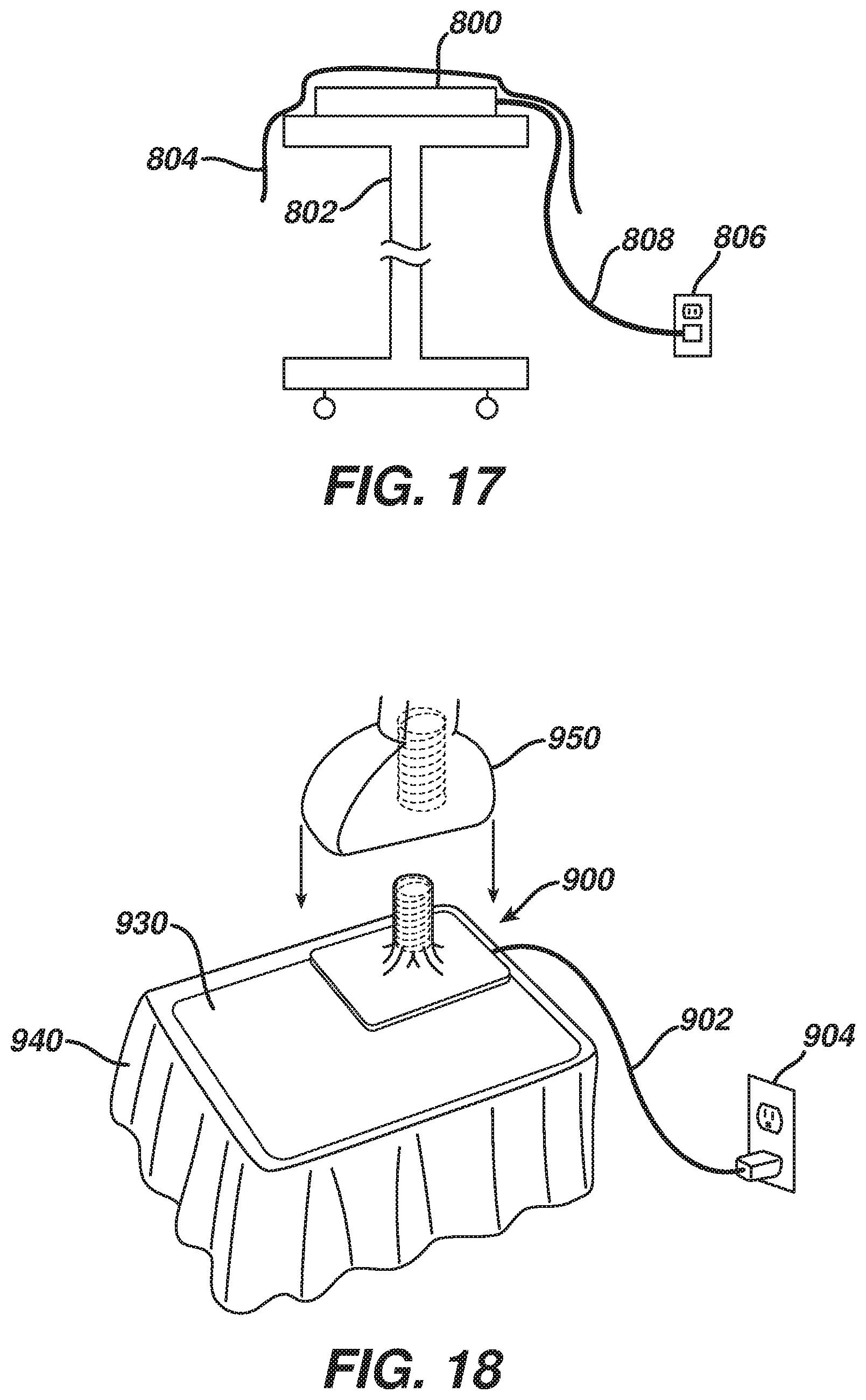
FIG. 17 depicts a schematic view of an exemplary inductive charging pad system;
FIG. 18 depicts a perspective view of an exemplary inductive charging peg system;
FIG. 19 depicts a partial cross-sectional view of the charging peg system of FIG. 18, including a coupled medical device; and
FIG. 20 depicts an exemplary medical device powered by supercapacitors, with a charging pad draped over a patient.
The drawings are not intended to be limiting in any way, and it is contemplated that various embodiments of the technology may be carried out in a variety of other ways, including those not necessarily depicted in the drawings. The accompanying drawings incorporated in and forming a part of the specification illustrate several aspects of the present technology, and together with the description serve to explain the principles of the technology; it being understood, however, that this technology is not limited to the precise arrangements shown.
DETAILED DESCRIPTION
The following description of certain examples of the technology should not be used to limit its scope. Other examples, features, aspects, embodiments, and advantages of the technology will become apparent to those skilled in the art from the following description, which is by way of illustration, one of the best modes contemplated for carrying out the technology. As will be realized, the technology described herein is capable of other different and obvious aspects, all without departing from the technology. Accordingly, the drawings and descriptions should be regarded as illustrative in nature and not restrictive.
I. Medical Devices for Use with Insertable or Reclaimable Components
FIG. 1 shows components of an exemplary medical device (10) in diagrammatic block form. As shown, medical device (10) comprises a control module (12), a power source (14), and an end effector (16). Merely exemplary power sources (14) may include NiMH batteries, Li-ion batteries (e.g., prismatic cell type lithium ion batteries, etc.), Ni-Cad batteries, or any other type of power source as may be apparent to one of ordinary skill in the art in light of the teachings herein. Control module (12) may comprise a microprocessor, an application specific integrated circuit (ASIC), memory, a printed circuit board (PCB), a storage device (such as a solid state drive or hard disk), firmware, software, or any other suitable control module components as will be apparent to one of ordinary skill in the art in light of the teachings herein. Control module (12) and power source (14) are coupled by an electrical connection (22), such as a cable and/or traces in a circuit board, etc., to transfer power from power source (14) to control module (12). Alternatively, power source (14) may be selectively coupled to control module (12). This allows power source (14) to be detached and removed from medical device (10), which may further allow power source (14) to be readily recharged or reclaimed for resterilization and reuse, such as in accordance with the various teachings herein. In addition or in the alternative, control module (12) may be removed for servicing, testing, replacement, or any other purpose as will be apparent to one of ordinary skill in the art in view of the teachings herein.
End effector (16) is coupled to control module (12) by another electrical connection (22). End effector (16) is configured to perform a desired function of medical device (10). By way of example only, such function may include cauterizing tissue, ablating tissue, severing tissue, ultrasonically vibrating, stapling tissue, or any other desired task for medical device (10). End effector (16) may thus include an active feature such as an ultrasonic blade, a pair of clamping jaws, a sharp knife, a staple driving assembly, a monopolar RF electrode, a pair of bipolar RF electrodes, a thermal heating element, and/or various other components. End effector (16) may also be removable from medical device (10) for servicing, testing, replacement, or any other purpose as will be apparent to one of ordinary skill in the art in view of the teachings herein. In some versions, end effector (16) is modular such that medical device (10) may be used with different kinds of end effectors (e.g., as taught in U.S. Provisional Application Ser. No. 61/410,603, etc.). Various other configurations of end effector (16) may be provided for a variety of different functions depending upon the purpose of medical device (10) as will be apparent to those of ordinary skill in the art in view of the teachings herein. Similarly, other types of components of a medical device (10) that may receive power from power source (14) will be apparent to those of ordinary skill in the art in view of the teachings herein.
Medical device (10) of the present example includes a trigger (18) and a sensor (20), though it should be understood that such components are merely optional. Trigger (18) is coupled to control module (12) and power source (14) by electrical connection (22). Trigger (18) may be configured to selectively provide power from power source (14) to end effector (16) (and/or to some other component of medical device (10)) to activate medical device (10) when performing a procedure. Sensor (20) is also coupled to control module (12) by an electrical connection (22) and may be configured to provide a variety of information to control module (12) during a procedure. By way of example only, such configurations may include sensing a temperature at end effector (16) or determining the oscillation rate of end effector (16). Data from sensor (20) may be processed by control module (12) to effect the delivery of power to end effector (16) (e.g., in a feedback loop, etc.). Various other configurations of sensor (20) may be provided depending upon the purpose of medical device (10) as will be apparent to those of ordinary skill in the art in view of the teachings herein. Of course, as with other components described herein, medical device (10) may have more than one sensor (20), or sensor (20) may simply be omitted if desired.
FIG. 2 depicts a merely exemplary form that medical device (10) may take. In particular, FIG. 2 shows a medical device (100) comprising a power source (110), a control module (120), a housing (130), end effector (140), and an electrical connection (150). In the present example, power source (110) is located internally within housing (130) of medical device (100). Alternatively, power source (110) may only partially extend into housing (130) and may be selectively attachable to a portion of housing (130). In yet a further exemplary configuration, a portion of housing (130) may extend into power source (110) and power source (110) may be selectively attachable to the portion of housing (130). Power source (110) may also be configured to detach from medical device (100) and decouple from control module (120) or electrical connection (150). As a result, power source (110) may be completely separated from medical device (100) in some versions. As is readily apparent, this may allow the power source (110) to be removed to be recharged or reclaimed for resterilization and reuse, such as in accordance with various teachings herein. After recharging, or after an initial charge, power source (110) may be inserted or reinserted into medical device (100) and secured to housing (130) or internally within housing (130). Of course, medical device (100) may also allow power source (110) to be charged and/or recharged while power source (110) is still in or otherwise coupled relative to housing (130).
It should also be understood that control module (120) may be removed for servicing, testing, replacement, or any other purpose as will be apparent to one of ordinary skill in the art in view of the teachings herein. Further, end effector (140) may also be removable from medical device (100) for servicing, testing, replacement, or any other purpose as will be apparent to one of ordinary skill in the art in view of the teachings herein. While certain configurations of an exemplary medical device (100) have been described, various other ways in which medical device (100) may be configured will be apparent to those of ordinary skill in the art in view of the teachings herein. By way of example only, medical devices (10, 100) and/or any other medical device referred to herein may be constructed in accordance with at least some of the teachings of U.S. Pat. Nos. 6,500,176; 7,416,101; 7,738,971; U.S. Pub. No. 2006/0079874, now abandoned; U.S. Pub. No. 2007/0191713, now abandoned; U.S. Pub. No. 2007/0282333, now abandoned; U.S. Pub. No. 2008/0200940, now abandoned; U.S. Pub. No. 2009/0209990, issued as U.S. Pat. No. 8,657,174 on Feb. 25, 2014; U.S. Pub. No. 2010/0069940, issued as U.S. Pat. No. 9,023,071 on May 5, 2015; and/or U.S. Provisional Application Ser. No. 61/410,603.
It is further understood that any one or more of the teachings, expressions, embodiments, examples, etc. described herein may be combined with any one or more of the other teachings, expressions, embodiments, examples, etc. that are described herein. The following-described teachings, expressions, embodiments, examples, etc. should therefore not be viewed in isolation relative to each other. Various suitable ways in which the teachings herein may be combined will be readily apparent to those of ordinary skill in the art in view of the teachings herein. Such modifications and variations are intended to be included within the scope of the claims.
It should also be understood that various teachings herein may be readily combined with various teachings in any of the following patent applications, all of which are filed on even date herewith and the disclosures of all of which are incorporated by reference herein: U.S. patent application Ser. No. 13/151,471, entitled "Medical Device Packaging with Charging Interface," published May 10, 2012 as U.S. Pub. No. 2012/0112690, issued as U.S. Pat. No. 9,000,720 on Apr. 7, 2015; U.S. patent application Ser. No. 13/151,481, entitled "Motor Driven Electrosurgical Device with Mechanical and Electrical Feedback," published May 10, 2012 as U.S. Pub. No. 2012/0116379, issued as U.S. Pat. No. 9,161,803 on Oct. 20, 2015; U.S. patent application Ser. No. 13/151,488, entitled "Packaging for Reclaimable Component of a Medical Device," published May 10, 2012 as U.S. Pub. No. 2012/0111591, now abandoned; U.S. patent application Ser. No. 13/151,498, entitled "Sterile Housing for Non-Sterile Medical Device Component" published May 10, 2012 as U.S. Pub. No. 2012/0115007, issued as U.S. Pat. No. 9,017,851 on Apr. 28, 2015; U.S. patent application Ser. No. 13/151,509, entitled "Medical Device Packaging with Window for Insertion of Reusable Component" published May 10, 2012 as U.S. Pub. No. 2012/0110824, issued as U.S. Pat. No. 9,089,338 on Jul. 28, 2015; U.S. patent application Ser. No. 13/151,512, entitled "Medical Device with Feature for Sterile Acceptance of Non-Sterile Reusable Component" published May 10, 2012 as U.S. Pub. No. 2012/0110810, issued as U.S. Pat. No. 9,072,523 on Jul. 7, 2015; and U.S. patent application Ser. No. 13/151,515, entitled "Sterile Package System for Medical Device," published Dec. 6, 2012 as U.S. Pub. No. 2012/0305427, issued as U.S. Pat. No. 10,080,813 on Sep. 25, 2018. Various suitable ways in which teachings herein may be combined with teachings of the above-referenced patent applications, as well as various ways in which teachings of the above-referenced patent applications may be combined together with or without teachings herein, will be apparent to those of ordinary skill in the art.
II. Exemplary Medical Device System Including Combined Integral Power Source and External Power Source
FIG. 3 shows an exemplary medical device (200) that includes an integral power source (218) and that also relies on external power. Medical device (200) of this example includes a handpiece (210), an end effector (212) disposed at the distal end of a shaft (214), and a trigger (216). Integral power source (218) is included within the handpiece (210) and selectively activates end effector (212) in accordance with actuations of trigger (216). By way of example only, end effector (212) may comprise a harmonic blade, a pair of clamping jaws, and/or one or more electrosurgical elements. It should be understood that medical device (200) may be constructed and operable in accordance with medical device (10, 100) and/or in accordance with at least some of the teachings of any of the references cited herein. Various other kinds of devices to which the teachings of medical device (200) may be applied will be apparent to those of ordinary skill in the art in view of the teachings herein.
In the present example, integral power source (218) includes a single battery. In particular, integral power source (218) in this example provides enough power in a single charge to activate end effector (212) one or more times during a normal use of medical device (200) in a medical procedure. However, integral power source (218) in this example does not necessarily provide enough power to activate end effector (212) as many times as needed during a normal use of medical device (200) in a medical procedure without providing at least some degree of recharging of integral power source (218). To that end, a relatively thin charging wire (230) is coupled with handpiece (210) at coupling (220). Charging wire (230) is also coupled with an adapter (232), which is further coupled with a conventional power cable (234). Power cable (234) is plugged into a conventional wall outlet (236), though it should be understood that charging wire (230), adapter (232), and/or power cable (234) may alternatively be coupled with a piece of capital equipment and/or some other component.
Charging wire (230) is operable to deliver enough power to integral power source (218) to sufficiently charge integral power source (218) during a normal use of medical device (200) in a medical procedure. However, in the present example, charging wire (230) does not have sufficient thickness to provide all power needed to activate end effector (212) during normal use of medical device (200) in a medical procedure. Thus, charging wire (230) and integral power source (218) work in tandem--with integral power source (218) being the primary power source for end effector (212) and with charging wire (230) being used to recharge integral power source (218) (e.g., between selective activations of end effector (212), etc.).
Charging wire (230) of the present example is also substantially thinner than conventional power cable (234). It should be understood that this may provide greater mobility for medical device (200) due to reduced weight pulling on handpiece (210), particularly if adapter (232) and cable (234) rest on the floor. As is also shown in FIG. 3, power cable (234) and adapter (232) are located in a non-sterile field (240) while charging wire (230) and the rest of medical device (200) are located in a sterile field (250) in the present example. It should be understood that this may facilitate re-use of power cable (234) and adapter (232) in various medical procedures with various medical devices (200), without having to re-sterilize power cable (234) and adapter (232) for each re-use. Of course, it may still be desirable to sterilize charging wire (230) and the rest of medical device (200) before medical device (200) is used in a medical procedure, regardless of whether charging wire (230) and/or other parts of medical device (200) are re-used in subsequent medical procedures. In instances where charging wire (230) and medical device (200) are provided in a sterile kit before use, integral power source (218) may be provided with a partial charge in the kit.
In some versions, using a single battery for integral power source (218) may help reduce the overall cost and weight of medical device (200). In other words, using a larger integral power source (218) that is capable of activating end effector (212) enough times during normal use of medical device (200) without such a power source (218) having to be recharged might result in a more expensive and/or heavier medical device (200). Of course, integral power source (218) may comprise more than one battery or may even comprise some kind of power source other than a battery. Furthermore, integral power source (218) may be configured to hold enough charge sufficient to activate end effector (212) enough times during normal use of medical device (200) without such a power source (218) having to be recharged.
FIG. 4 shows coupling (220) of the present example in greater detail. As shown, coupling (220) a first magnet (222) integral with handpiece (210) and a second magnet (224) integral with a strain relief (226) on wire (230). In the present example, magnets (222, 224) provide relatively quick and easy coupling/decoupling of wire (230) and handpiece (210). In some versions, handpiece (210) and wire (230) also present complementary contacts, prongs and sockets, and/or other features to provide electrical communication from wire (230) to integral power source (218). Magnets (222, 224) may be located adjacent to such electrical communication features. Handpiece (210) and/or wire (230) may also include one or more bosses or other guide features configured to facilitate proper coupling of wire (230) with handpiece (210). It should also be understood that magnets (222, 224) are merely optional, and that a variety of other types of features may be used, including but not limited to latches, clamps, clips, friction fittings, etc.
In some instances, a surgeon may wish to decouple wire (230) from handpiece (210) to provide greater mobility or positioning of medical device (200). In such instances, wire (230) may be readily re-coupled with handpiece (210) at coupling (220), even in the operating room, to provide any additional charge that may be needed for integral power source (218) after one or more activations of end effector (212). Furthermore, handpiece (210) or some other component of medical device (200) may include a charge indicator, providing a visual and/or audio indication of the charge state of power source (218), thereby alerting the surgeon to when power source (218) needs to be recharged. Still other suitable components, features, configurations, and operabilities of medical device (200) will be apparent to those of ordinary skill in the art in view of the teachings herein.
III. Exemplary Medical Device Kit Including Electronic Component Charging and Reclamation Features
FIGS. 5-9 show an exemplary kit (300) and its various components, including a medical device (310), batteries (320), a control module (330) (e.g., printed circuit board, generator board, etc.), and a reclamation bag (340), all of which are positioned in respective compartments of packaging (350). Packaging (350) of the present example comprises a sterile blister pack, though it should be understood that packaging (350) may take any other suitable form. In some versions, packaging (350) is constructed in accordance with the teachings of U.S. patent application Ser. No. 13/151,515, entitled "Sterile Package System for Medical Device," filed Jun. 2, 2011, published Dec. 6, 2012 as U.S. Pub. No. 2012/0305427, issued as U.S. Pat. No. 10,080,813 on Sep. 25, 2018, the disclosure of which is incorporated by reference herein. For instance, such a form of packaging (350) may facilitate sterilization and sealing of medical device (310) separate from sterilization and sealing of batteries (320) and control module (330). Various other suitable ways in which packaging (350) may be configured will be apparent to those of ordinary skill in the art in view of the teachings herein.
Medical device (310) of the present example includes a handpiece (312), an end effector (314) disposed at the distal end of a shaft (316), and a trigger (318). As shown in FIG. 7, handpiece (312) includes a first slot (360) configured to receive battery (320) and a second slot (370) configured to receive control module (330). Such slots (360, 370) may include latching features configured to selectively retain battery (320) and control module (330) in handpiece (312) after insertion. Slots (360, 370) may also include leads sufficient to establish electrical communication with inserted battery (320) and control module (330). By way of example only, either slot (360, 370) may be configured in accordance with the teachings of U.S. patent application Ser. No. 13/151,512, entitled "Medical Device with Feature for Sterile Acceptance of Non-Sterile Reusable Component," filed Jun. 2, 2011, published May 10, 2012 as U.S. Pub. No. 2012/0110810, issued as U.S. Pat. No. 9,072,523 on Jul. 7, 2015, the disclosure of which is incorporated by reference herein. Other suitable configurations for slots (360, 370) will be apparent to those of ordinary skill in the art in view of the teachings herein. In some versions, a charged battery (320) is preloaded in handpiece (312), such that medical device (310) is immediately ready for use upon removal from packaging (350). In some such instances, remaining batteries (320) in packaging (350) are simply relied on for backup in the event that the preloaded battery (320) loses sufficient charge.
Once coupled with handpiece (312), battery (320) and control module (330) cooperate to selectively activate end effector (314) in accordance with actuations of trigger (318). As also shown in FIG. 7, handpiece (312) of the present example also includes a battery life indicator (362), which is operable to indicate how much charge is left in battery (320). As with other components described herein, battery life indicator (362) is merely optional. If the charge level of a battery (320) gets too low during a medical procedure, the user may simply eject battery (320) as described below and use another, fully charged battery (320) from packaging (350). In some instances, having several batteries (320) on hand in packaging (350) may facilitate use of relatively small batteries (320), which may in turn reduce the overall weight of medical device (310) during use of medical device (310) in a medical procedure. Extra batteries (320) may continue to be charged in packaging (350) during the medical procedure.
By way of example only, end effector (314) may comprise a harmonic blade, a pair of clamping jaws, and/or one or more electrosurgical elements. It should be understood that medical device (310) may be constructed and operable in accordance with medical device (10, 100) and/or in accordance with at least some of the teachings of any of the references cited herein. Various other kinds of devices to which the teachings of medical device (310) may be applied will be apparent to those of ordinary skill in the art in view of the teachings herein.
As best seen in FIG. 6, kit (300) also includes a power cord (322) coupled with batteries (320). In the present example, power cord (322) is coupled with batteries (320) via a charger (324) that is integral with packaging (350) (e.g., disposed within a recess formed by packaging (350), etc.). When plugged into a conventional wall outlet (326) (or some other power source), power cord (322) is operable to charge batteries (320). In some versions, kit (300) is shipped and stored with batteries (320) having only a partial charge, such that batteries (320) need to be charged before medical device (310) is used in a medical procedure. In other words, in an exemplary use, a user may initially receive kit (300) in the form shown in FIG. 5, which may include a peelable film cover, lid, or other removable feature. Right before medical device (310) is to be used in a medical procedure, the user may place kit (300) on a mayo stand in the operating room (or place kit (300) elsewhere), remove the film cover, lid, or other removable feature, and then plug power cord (322) into wall outlet (326) as shown in FIG. 6. Charger (324), packaging (350), and/or batteries (320) may include visual and/or audio indicators configured to convey the charge state of batteries (320) to the user. Once batteries (320) are sufficiently charged, the user may then insert battery (320) and control module (330) into respective slots (360, 370) of handpiece (312), as shown in FIG. 7. Medical device (310) is then ready to be used in a medical procedure.
Handpiece (312) of the present example also includes a component ejection feature (380), which includes a button and a spring-loaded release mechanism. As shown in FIG. 8, component ejection feature (380) is operable to eject control module (330) and battery (320) from handpiece (312). In some versions, a single component ejection feature (380) simultaneously ejects both battery (320) and control module (330). In some other versions, separate component ejection features (380) are provided for independent ejection of battery (320) and control module (330). It should be understood that it may be desirable in some instances to eject battery (320) and/or control module (330) from medical device (310), such as after the medical procedure is complete. For instance, it may be desirable in some instances to dispose of battery (320) and/or control module (330) separate from disposal of other components of medical device (310), such as to avoid environmental concerns.
As another merely illustrative example, it may be desirable in some instances to separately collect batteries (320) and/or control module (330) for reclamation (e.g., cleaning and re-sterilization, etc.) and re-use. For instance, this may be desirable where battery (320) and/or control module (330) are relatively high cost items; and/or to again avoid environmental concerns that might be associated with simple disposal of battery (320) and/or control module (330). As shown in FIG. 9, reclamation bag (340) may be used to collect used batteries (320), control module (330), and/or other components (e.g., charger (324), etc.). Filled reclamation bag (340) may then be sent off to reclaim, salvage, or otherwise further process the components contained therein, with the remainder of kit (300) being discarded or otherwise disposed of. In the present example, reclamation bag (340) includes a drawstring (342), though it should be understood that any other suitable type of closure feature may be used.
In some versions, control module (330) is not removable from medical device (310), such that only battery (320) is removable from medical device (310). Similarly, in some versions control module (330) is removable from medical device (310) and either battery (320) is non-removable or medical device (310) receives power from some other source. It should also be understood that charger (324) or some other feature of kit (300) may be configured to safely discharge batteries (320) before batteries (320) are disposed of or sent off for reclamation/processing in reclamation bag (340). Still other suitable components, features, configurations, and operabilities of kit (300) will be apparent to those of ordinary skill in the art in view of the teachings herein.
IV. Exemplary Medical Device Conductive Charging Stations
As noted above, in medical devices having internal power sources such as batteries, etc., it may be necessary to charge or recharge such internal power sources before and/or during use of the medical device in a medical procedure. In some instances, this may require physically coupling (e.g., via contact) a component of the medical device with a component of a docking station or other type of charging device. In some settings, such physical contact may present concerns as to sterility. In particular, such as situations where the docking station or other charging device is re-used, it may be desirable in some instances to provide ready re-use of such a docking station or other charging device without necessarily having to fully re-sterilize the docking station or other charging device between uses. Thus, in some situations where the docking station or other charging device is not sterile, it may be desirable to prevent such non-sterility from contaminating a sterile medical device when some degree of contact is required between the docking station or other charging device and the medical device in order to charge/recharge the medical device. The following examples present ways in which a non-sterile charging device may be used to charge a sterile medical device without compromising the sterility of the medical device despite some degree of contact with the medical device. Further examples and variations will be apparent to those of ordinary skill in the art in view of the teachings herein.
A. Exemplary Charging Station with Sterile Barrier
FIGS. 10-12 show an exemplary charging station (400) that includes a base (410), a film (420), and a collar (430). Charging station (400) is shown as coupling with a handpiece (450) of a medical device. As shown in FIG. 12, handpiece (450) includes an integral power source (460) and a pair of contacts (462) that are coupled with power source (460) via wires (464). Power source (460) may comprise one or more batteries and/or various other components. Contacts (462) are recessed within handpiece (450) in this example. In some versions, contacts (462) define or are provided in respective sockets. It should be understood that the medical device having handpiece (450) may be constructed and operable in accordance with medical device (10, 100) and/or in accordance with at least some of the teachings of any of the references cited herein. Various other types of devices that may include handpiece (450) will be apparent to those of ordinary skill in the art in view of the teachings herein.
Base (410) includes a power cord (412) that is configured to plug into a conventional wall outlet or a piece of capital equipment. A pair of spike contacts (414) protrude upwardly from base (410). While spike contacts (414) have a sharp conical shape in the present example, it should be understood that contacts (414) may have any other suitable shape. Contacts (462) of handpiece (450) are configured to receive spike contacts (414) when handpiece is coupled with charging station (400), such that spike contacts (414) are operable to charge power source (460). Collar (430) is configured to insertingly receive a lower portion of handpiece (450) and is configured to provide structural support to handpiece (450). In particular, collar (430) has angled sidewalls (432) providing a tapered configuration, which helps prevent handpiece (450) and collar (430) from tipping over. While contacts (414) are shown protruding upwardly from base (410), it should be understood that the contacts (414) could alternatively reside and point downwardly from within handpiece (450) and make contact with contacts of base (410).
Film (420) comprises a sterile sheet of plastic film, and is configured to provide a sterile barrier between the exterior of sterile handpiece (450) and non-sterile base (410). In particular, film (420) is interposed between handpiece (450) and base (410). In the present example, collar (430) is also sterile, and is also positioned above film (420). It should be understood, however, that film (420) may optionally be draped over collar (430), and that film (420) may deform when handpiece (450) is inserted in collar (430), such that film (420) may serve as a sterile barrier between the sterile exterior of handpiece (450) and a non-sterile collar (430). As best seen in FIG. 10, film (420) of the present example includes a pair of openings (422) associated with spike contacts (414). In particular, openings (422) are sized and configured to permit passage of spike contacts (414) therethrough. In some other versions, openings (422) are eliminated, and spike contacts (414) pierce and poke through film (420) when handpiece (450) is pressed onto base (410) through collar (430).
In some versions, spike contacts (414) are selectively retractable within base (410). For instance, spike contacts (414) may be retracted in base (410) as charging station (400) is being prepared for use, as shown in FIG. 10. Base (410) may include an actuating mechanism (not shown) that is operable to deploy spike contacts (414) at an appropriate time. Such a mechanism may employ springs, solenoids, and/or various other types of components to deploy spike contacts (414). By way of example only, base (410) may include a button, switch, slider, or other feature operable to selectively activate such an actuation mechanism. As another merely illustrative example, base (410) may include a feature that is responsive to placement of collar (430) and/or handpiece (450) against base (410), such that spike contacts (414) deploy upon placement of collar (430) and/or handpiece (450) against base (410).
In some other versions, spike contacts (414) are integral features of collar (430) instead of being integral features of base (410). For instance, base (410) may present a pair of contacts that mate with complementary contacts o
D00000
D00001
D00002
D00003
D00004
D00005
D00006
D00007
D00008
D00009
D00010
D00011
D00012

XML
uspto.report is an independent third-party trademark research tool that is not affiliated, endorsed, or sponsored by the United States Patent and Trademark Office (USPTO) or any other governmental organization. The information provided by uspto.report is based on publicly available data at the time of writing and is intended for informational purposes only.
While we strive to provide accurate and up-to-date information, we do not guarantee the accuracy, completeness, reliability, or suitability of the information displayed on this site. The use of this site is at your own risk. Any reliance you place on such information is therefore strictly at your own risk.
All official trademark data, including owner information, should be verified by visiting the official USPTO website at www.uspto.gov. This site is not intended to replace professional legal advice and should not be used as a substitute for consulting with a legal professional who is knowledgeable about trademark law.