Shuttering of aerosol streams
Christenson , et al.
U.S. patent number 10,632,746 [Application Number 16/190,007] was granted by the patent office on 2020-04-28 for shuttering of aerosol streams. This patent grant is currently assigned to Optomec, Inc.. The grantee listed for this patent is Optomec, Inc.. Invention is credited to Kurt K. Christenson, Chad Conroy, James Q. Feng, John David Hamre, Jason A. Paulsen, Michael J. Renn.


| United States Patent | 10,632,746 |
| Christenson , et al. | April 28, 2020 |
Shuttering of aerosol streams
Abstract
Methods and apparatuses for controlling aerosol streams being deposited onto a substrate via pneumatic shuttering. The aerosol stream is surrounded and focused by an annular co-flowing sheath gas in the print head of the apparatus. A boost gas flows to a vacuum pump during printing of the aerosol. A valve adds the boost gas to the sheath gas at the appropriate time, and a portion of the two gases is deflected in a direction opposite to the aerosol flow direction to at least partially prevent the aerosol from passing through the deposition nozzle. Some or all of the aerosol is combined with that portion of the boost gas and sheath gas and is exhausted from the print head. By precisely balancing the flows into and out of the print head, maintaining the flow rates of the aerosol and sheath gas approximately constant, and keeping the boost gas flowing during both printing and shuttering, the transition time between printing and partial or full shuttering of the aerosol stream is minimized. The pneumatic shuttering can be combined with a mechanical shutter for faster operation. A pre-sheath gas can be used to minimize the delay between the flow of gas in the center and the flow of gas near the sides of the print head flow channel.
| Inventors: | Christenson; Kurt K. (Minnetonka, MN), Renn; Michael J. (New Richmond, WI), Paulsen; Jason A. (Cedar Rapids, IA), Hamre; John David (Plymouth, MN), Conroy; Chad (Minneapolis, MN), Feng; James Q. (Maple Grove, MN) | ||||||||||
|---|---|---|---|---|---|---|---|---|---|---|---|
| Applicant: |
|
||||||||||
| Assignee: | Optomec, Inc. (Albuquerque,
NM) |
||||||||||
| Family ID: | 66431717 | ||||||||||
| Appl. No.: | 16/190,007 | ||||||||||
| Filed: | November 13, 2018 |
Prior Publication Data
| Document Identifier | Publication Date | |
|---|---|---|
| US 20190143678 A1 | May 16, 2019 | |
Related U.S. Patent Documents
| Application Number | Filing Date | Patent Number | Issue Date | ||
|---|---|---|---|---|---|
| 62585449 | Nov 13, 2017 | ||||
| Current U.S. Class: | 1/1 |
| Current CPC Class: | B41J 2/11 (20130101); B41J 2/175 (20130101); B05B 1/30 (20130101); B05B 12/18 (20180201); B05B 7/12 (20130101); B05B 7/0012 (20130101); B05B 12/06 (20130101) |
| Current International Class: | B41J 2/11 (20060101); B41J 2/175 (20060101); B05B 1/30 (20060101); B05B 7/00 (20060101); B05B 7/12 (20060101); B05B 12/18 (20180101) |
References Cited [Referenced By]
U.S. Patent Documents
| 3474971 | October 1969 | Goodrich |
| 3590477 | July 1971 | Cheroff et al. |
| 3642202 | February 1972 | Angelo |
| 3715785 | February 1973 | Brown et al. |
| 3777983 | December 1973 | Hibbins |
| 3808550 | March 1974 | Ashkin |
| 3808432 | April 1974 | Ashkin |
| 3816025 | June 1974 | O'Neill |
| 3846661 | November 1974 | Brown et al. |
| 3854321 | December 1974 | Dahneke |
| 3901798 | August 1975 | Peterson |
| 3959798 | May 1976 | Hochberg et al. |
| 3974769 | August 1976 | Hochberg et al. |
| 3982251 | September 1976 | Hochberg |
| 4004733 | January 1977 | Law |
| 4016417 | April 1977 | Benton |
| 4019188 | April 1977 | Hochberg et al. |
| 4034025 | July 1977 | Martner |
| 4036434 | July 1977 | Anderson et al. |
| 4046073 | September 1977 | Mitchell et al. |
| 4046074 | September 1977 | Hochberg et al. |
| 4073436 | February 1978 | Behr |
| 4092535 | May 1978 | Ashkin et al. |
| 4112437 | September 1978 | Mir et al. |
| 4132894 | January 1979 | Yule |
| 4171096 | October 1979 | Welsh et al. |
| 4200669 | April 1980 | Schaefer et al. |
| 4228440 | October 1980 | Horike et al. |
| 4235563 | November 1980 | Hine et al. |
| 4269868 | May 1981 | Livsey |
| 4323756 | April 1982 | Brown et al. |
| 4400408 | August 1983 | Asano et al. |
| 4453803 | June 1984 | Hidaka et al. |
| 4485387 | November 1984 | Drumheller |
| 4497692 | February 1985 | Gelchinski et al. |
| 4601921 | July 1986 | Lee |
| 4605574 | August 1986 | Yonehara et al. |
| 4670135 | June 1987 | Marple et al. |
| 4685563 | August 1987 | Cohen et al. |
| 4689052 | August 1987 | Ogren et al. |
| 4694136 | September 1987 | Kasner et al. |
| 4724299 | February 1988 | Hammeke |
| 4733018 | March 1988 | Prabhu et al. |
| 4823009 | April 1989 | Biemann et al. |
| 4825299 | April 1989 | Okada et al. |
| 4826583 | May 1989 | Biernaux et al. |
| 4893886 | January 1990 | Ashkin et al. |
| 4904621 | February 1990 | Loewenstein et al. |
| 4911365 | March 1990 | Thiel et al. |
| 4917830 | April 1990 | Ortiz et al. |
| 4920254 | April 1990 | Decamp et al. |
| 4927992 | May 1990 | Whitlow et al. |
| 4947463 | August 1990 | Matsuda et al. |
| 4971251 | November 1990 | Dobrick et al. |
| 4978067 | December 1990 | Berger et al. |
| 4997809 | March 1991 | Gupta |
| 5032850 | July 1991 | Andeen et al. |
| 5038014 | August 1991 | Pratt et al. |
| 5043548 | August 1991 | Whitney et al. |
| 5064685 | November 1991 | Kestenbaum et al. |
| 5126102 | June 1992 | Takahashi et al. |
| 5164535 | November 1992 | Leasure |
| 5170890 | December 1992 | Wilson et al. |
| 5173220 | December 1992 | Reiff et al. |
| 5176328 | January 1993 | Alexander |
| 5176744 | January 1993 | Muller |
| 5182430 | January 1993 | Lagain |
| 5194297 | March 1993 | Scheer et al. |
| 5208431 | May 1993 | Uchiyama et al. |
| 5245404 | September 1993 | Jannson et al. |
| 5250383 | October 1993 | Naruse |
| 5254832 | October 1993 | Gartner et al. |
| 5270542 | December 1993 | McMurry et al. |
| 5292418 | March 1994 | Morita et al. |
| 5294459 | March 1994 | Hogan et al. |
| 5306447 | April 1994 | Harris et al. |
| 5322221 | June 1994 | Anderson |
| 5335000 | August 1994 | Stevens |
| 5343434 | August 1994 | Noguchi |
| 5344676 | September 1994 | Kim et al. |
| 5359172 | October 1994 | Kozak et al. |
| 5366559 | November 1994 | Periasamy |
| 5378505 | January 1995 | Kubota et al. |
| 5378508 | January 1995 | Castro et al. |
| 5393613 | February 1995 | MacKay |
| 5398193 | March 1995 | Deangelis |
| 5403617 | April 1995 | Haaland |
| 5405660 | April 1995 | Psiuk et al. |
| 5418350 | May 1995 | Freneaux et al. |
| 5449536 | September 1995 | Funkhouser |
| 5477026 | December 1995 | Buongiorno |
| 5486676 | January 1996 | Aleshin |
| 5491317 | February 1996 | Pirl |
| 5495105 | February 1996 | Nishimura et al. |
| 5512745 | April 1996 | Finer et al. |
| 5518680 | May 1996 | Cima et al. |
| 5524828 | June 1996 | Raterman et al. |
| 5529634 | June 1996 | Miyata et al. |
| 5547094 | August 1996 | Bartels et al. |
| 5578227 | November 1996 | Rabinovich |
| 5607730 | March 1997 | Ranalli |
| 5609921 | March 1997 | Gitzhofer et al. |
| 5612099 | March 1997 | Thaler |
| 5614252 | March 1997 | McMillan et al. |
| 5634093 | May 1997 | Ashida et al. |
| 5648127 | July 1997 | Turchan et al. |
| 5653925 | August 1997 | Batchelder |
| 5676719 | October 1997 | Stavropoulos et al. |
| 5697046 | December 1997 | Conley |
| 5705117 | January 1998 | O'Connor et al. |
| 5707715 | January 1998 | Derochemont et al. |
| 5732885 | March 1998 | Huffman |
| 5733609 | March 1998 | Wang |
| 5736195 | April 1998 | Haaland |
| 5742050 | April 1998 | Amirav et al. |
| 5775402 | April 1998 | Sachs et al. |
| 5746844 | May 1998 | Sterett et al. |
| 5770272 | June 1998 | Biemann et al. |
| 5772106 | June 1998 | Ayers et al. |
| 5772963 | June 1998 | Prevost et al. |
| 5772964 | June 1998 | Prevost et al. |
| 5779833 | July 1998 | Cawley et al. |
| 5795388 | August 1998 | Oudard |
| 5814152 | September 1998 | Thaler |
| 5837960 | November 1998 | Lewis et al. |
| 5844192 | December 1998 | Wright et al. |
| 5847357 | December 1998 | Woodmansee et al. |
| 5849238 | December 1998 | Schmidt et al. |
| 5854311 | December 1998 | Richart |
| 5861136 | January 1999 | Glicksman et al. |
| 5882722 | March 1999 | Kydd |
| 5894403 | April 1999 | Shah et al. |
| 5940099 | August 1999 | Karlinski |
| 5958268 | September 1999 | Engelsberg et al. |
| 5965212 | October 1999 | Dobson et al. |
| 5980998 | November 1999 | Sharma et al. |
| 5993549 | November 1999 | Kindler et al. |
| 5993554 | November 1999 | Keicher et al. |
| 5997956 | December 1999 | Hunt et al. |
| 6007631 | December 1999 | Prentice et al. |
| 6015083 | January 2000 | Hayes et al. |
| 6021776 | February 2000 | Allred et al. |
| 6025037 | February 2000 | Wadman et al. |
| 6036889 | March 2000 | Kydd |
| 6040016 | March 2000 | Mitani et al. |
| 6046426 | April 2000 | Jeantette et al. |
| 6056994 | May 2000 | Paz De Araujo et al. |
| 6110144 | August 2000 | Choh et al. |
| 6116718 | September 2000 | Peeters et al. |
| 6136442 | October 2000 | Wong |
| 6143116 | November 2000 | Hayashi et al. |
| 6144008 | November 2000 | Rabinovich |
| 6149076 | November 2000 | Riney |
| 6151435 | November 2000 | Pilloff |
| 6159749 | December 2000 | Liu |
| 6169605 | January 2001 | Penn et al. |
| 6176647 | January 2001 | Itoh |
| 6182688 | February 2001 | Fabre |
| 6183690 | February 2001 | Yoo et al. |
| 6197366 | March 2001 | Takamatsu |
| 6251488 | June 2001 | Miller et al. |
| 6258733 | July 2001 | Solayappan et al. |
| 6265050 | July 2001 | Wong et al. |
| 6267301 | July 2001 | Haruch |
| 6268584 | July 2001 | Keicher et al. |
| 6290342 | September 2001 | Vo et al. |
| 6291088 | September 2001 | Wong |
| 6293659 | September 2001 | Floyd et al. |
| 6318642 | November 2001 | Goenka et al. |
| 6328026 | December 2001 | Wang et al. |
| 6340216 | January 2002 | Peeters et al. |
| 6348687 | February 2002 | Brockmann et al. |
| 6349668 | February 2002 | Sun et al. |
| 6355533 | March 2002 | Lee |
| 6379745 | April 2002 | Kydd et al. |
| 6384365 | May 2002 | Seth et al. |
| 6390115 | May 2002 | Rohwer et al. |
| 6391251 | May 2002 | Keicher et al. |
| 6391494 | May 2002 | Reitz et al. |
| 6405095 | June 2002 | Jang et al. |
| 6406137 | June 2002 | Okazaki et al. |
| 6410105 | June 2002 | Mazumder et al. |
| 6416156 | July 2002 | Noolandi et al. |
| 6416157 | July 2002 | Peeters et al. |
| 6416158 | July 2002 | Floyd et al. |
| 6416159 | July 2002 | Floyd et al. |
| 6416389 | July 2002 | Perry et al. |
| 6454384 | September 2002 | Peeters et al. |
| 6467862 | October 2002 | Peeters et al. |
| 6471327 | October 2002 | Jagannathan et al. |
| 6481074 | November 2002 | Karlinski |
| 6486432 | November 2002 | Colby et al. |
| 6503831 | January 2003 | Speakman |
| 6513736 | February 2003 | Skeath et al. |
| 6520996 | February 2003 | Manasas et al. |
| 6521297 | February 2003 | McDougall et al. |
| 6537501 | March 2003 | Holl et al. |
| 6544599 | April 2003 | Brown et al. |
| 6548122 | April 2003 | Sharma et al. |
| 6564038 | May 2003 | Bethea et al. |
| 6572033 | June 2003 | Pullagura et al. |
| 6573491 | June 2003 | Marchitto et al. |
| 6607597 | August 2003 | James et al. |
| 6608281 | August 2003 | Ishide et al. |
| 6636676 | October 2003 | Renn |
| 6646253 | November 2003 | Rohwer et al. |
| 6656409 | December 2003 | Keicher et al. |
| 6697694 | February 2004 | Mogensen |
| 6772649 | August 2004 | Zimmermann et al. |
| 6774338 | August 2004 | Baker et al. |
| 6780377 | August 2004 | Hall et al. |
| 6811744 | November 2004 | Keicher et al. |
| 6811805 | November 2004 | Gilliard et al. |
| 6823124 | November 2004 | Renn et al. |
| 6855631 | February 2005 | Kirby |
| 6890624 | May 2005 | Kambe et al. |
| 6921626 | July 2005 | Ray et al. |
| 6998345 | February 2006 | Kirby |
| 6998785 | February 2006 | Silfvast et al. |
| 7009137 | March 2006 | Guo et al. |
| 7045015 | May 2006 | Renn et al. |
| 7108894 | September 2006 | Renn |
| 7164818 | January 2007 | Bryan et al. |
| 7171093 | January 2007 | Kringlebotn et al. |
| 7178380 | February 2007 | Shekarriz et al. |
| 7270844 | September 2007 | Renn |
| 7294366 | November 2007 | Renn et al. |
| 7402897 | July 2008 | Leedy |
| 7469558 | December 2008 | Demaray et al. |
| 7485345 | February 2009 | Renn et al. |
| 7658163 | February 2010 | Renn et al. |
| 7674671 | March 2010 | Renn |
| 7836922 | November 2010 | Poole et al. |
| 7938079 | May 2011 | King et al. |
| 7987813 | August 2011 | Renn et al. |
| 8012235 | September 2011 | Takashima et al. |
| 8383014 | February 2013 | Vandeusden et al. |
| 8796146 | August 2014 | Renn et al. |
| 8887658 | November 2014 | Essien |
| 8916084 | December 2014 | Chretien et al. |
| 8919899 | December 2014 | Essien |
| 9694389 | July 2017 | Fan et al. |
| 10058881 | August 2018 | Keicher |
| 2001/0027011 | October 2001 | Hanaoka et al. |
| 2001/0046551 | November 2001 | Falck et al. |
| 2002/0012743 | January 2002 | Sampath et al. |
| 2002/0012752 | January 2002 | McDougall et al. |
| 2002/0063117 | May 2002 | Church et al. |
| 2002/0071934 | June 2002 | Marutsuka |
| 2002/0082741 | June 2002 | Mazumder et al. |
| 2002/0096647 | July 2002 | Moors et al. |
| 2002/0100416 | August 2002 | Sun |
| 2002/0107140 | August 2002 | Hampden-Smith et al. |
| 2002/0128714 | September 2002 | Manasas et al. |
| 2002/0132051 | September 2002 | Choy |
| 2002/0145213 | October 2002 | Liu et al. |
| 2002/0162974 | November 2002 | Orsini et al. |
| 2003/0003241 | January 2003 | Suzuki et al. |
| 2003/0020768 | January 2003 | Renn |
| 2003/0032214 | February 2003 | Huang |
| 2003/0048314 | March 2003 | Renn |
| 2003/0108511 | June 2003 | Sawhney |
| 2003/0108664 | June 2003 | Kodas et al. |
| 2003/0117691 | June 2003 | Bi et al. |
| 2003/0138967 | July 2003 | Hall et al. |
| 2003/0149505 | August 2003 | Mogensen |
| 2003/0175411 | September 2003 | Kodas et al. |
| 2003/0180451 | September 2003 | Kodas et al. |
| 2003/0202043 | October 2003 | Moffat et al. |
| 2003/0219923 | November 2003 | Nathan et al. |
| 2003/0228124 | December 2003 | Renn et al. |
| 2004/0004209 | January 2004 | Matsuba et al. |
| 2004/0029706 | February 2004 | Barrera et al. |
| 2004/0038808 | February 2004 | Hampden-Smith et al. |
| 2004/0080917 | April 2004 | Steddom et al. |
| 2004/0151978 | August 2004 | Huang |
| 2004/0179808 | September 2004 | Renn |
| 2004/0185388 | September 2004 | Hirai |
| 2004/0191695 | September 2004 | Ray et al. |
| 2004/0197493 | October 2004 | Renn |
| 2004/0227227 | November 2004 | Imanaka et al. |
| 2004/0247782 | December 2004 | Hampden-Smith et al. |
| 2005/0002818 | January 2005 | Ichikawa |
| 2005/0003658 | January 2005 | Kirby |
| 2005/0046664 | March 2005 | Renn |
| 2005/0097987 | May 2005 | Kodas et al. |
| 2005/0101129 | May 2005 | Lirby |
| 2005/0110064 | May 2005 | Duan et al. |
| 2005/0129383 | June 2005 | Renn et al. |
| 2005/0133527 | June 2005 | Dullea et al. |
| 2005/0145968 | July 2005 | Goela et al. |
| 2005/0147749 | July 2005 | Liu et al. |
| 2005/0156991 | July 2005 | Renn |
| 2005/0163917 | July 2005 | Renn |
| 2005/0184328 | August 2005 | Uchiyama et al. |
| 2005/0205415 | September 2005 | Belousov et al. |
| 2005/0205696 | September 2005 | Saito et al. |
| 2005/0214480 | September 2005 | Garbar et al. |
| 2005/0215689 | September 2005 | Garbar et al. |
| 2005/0238804 | October 2005 | Garbar et al. |
| 2005/0247681 | November 2005 | Boillot et al. |
| 2005/0275143 | December 2005 | Toth |
| 2006/0003095 | January 2006 | Bullen et al. |
| 2006/0008590 | January 2006 | King et al. |
| 2006/0035033 | February 2006 | Tanahashi |
| 2006/0043598 | March 2006 | Kirby et al. |
| 2006/0046347 | March 2006 | Wood et al. |
| 2006/0046461 | March 2006 | Benson et al. |
| 2006/0057014 | March 2006 | Oda et al. |
| 2006/0116000 | June 2006 | Yamamoto |
| 2006/0159899 | July 2006 | Edwards et al. |
| 2006/0162424 | July 2006 | Shekarriz et al. |
| 2006/0163570 | July 2006 | Renn et al. |
| 2006/0163744 | July 2006 | Vanheusden et al. |
| 2006/0172073 | August 2006 | Groza et al. |
| 2006/0175431 | August 2006 | Renn et al. |
| 2006/0189113 | August 2006 | Vanheusden et al. |
| 2006/0233953 | October 2006 | Renn et al. |
| 2006/0280866 | December 2006 | Marquez et al. |
| 2007/0019028 | January 2007 | Renn et al. |
| 2007/0128905 | June 2007 | Speakman |
| 2007/0154634 | July 2007 | Renn |
| 2007/0181060 | August 2007 | Renn et al. |
| 2007/0240454 | October 2007 | Brown |
| 2008/0013299 | January 2008 | Renn |
| 2008/0099456 | May 2008 | Schwenke et al. |
| 2009/0039249 | February 2009 | Wang |
| 2009/0061077 | March 2009 | King et al. |
| 2009/0061089 | March 2009 | King et al. |
| 2009/0090298 | April 2009 | King et al. |
| 2009/0114151 | May 2009 | Renn et al. |
| 2009/0229412 | September 2009 | Takashima et al. |
| 2009/0252874 | October 2009 | Essien |
| 2010/0112234 | June 2010 | Spatz et al. |
| 2010/0140811 | June 2010 | Leal et al. |
| 2010/0173088 | July 2010 | King |
| 2010/0192847 | August 2010 | Renn et al. |
| 2010/0255209 | October 2010 | Renn et al. |
| 2011/0129615 | June 2011 | Renn et al. |
| 2012/0038716 | February 2012 | Hoerteis |
| 2013/0029032 | January 2013 | King et al. |
| 2013/0260056 | October 2013 | Renn et al. |
| 2013/0283700 | October 2013 | Bajaj et al. |
| 2014/0035975 | February 2014 | Essien et al. |
| 2014/0342082 | November 2014 | Renn |
| 2015/0217517 | August 2015 | Karpas |
| 2016/0172741 | June 2016 | Panat et al. |
| 2016/0193627 | July 2016 | Essien |
| 2016/0229119 | August 2016 | Renn |
| 2016/0242296 | August 2016 | Deangelis |
| 2017/0177319 | June 2017 | Mark et al. |
| 2017/0348903 | December 2017 | Renn et al. |
| 2018/0015730 | January 2018 | Essien |
| 2078199 | Jun 1991 | CN | |||
| 1452554 | Oct 2003 | CN | |||
| 101111129 | Jan 2008 | CN | |||
| 19841401 | Apr 2000 | DE | |||
| 0331022 | Sep 1989 | EP | |||
| 0444550 | Sep 1991 | EP | |||
| 0470911 | Jul 1994 | EP | |||
| 1258293 | Nov 2002 | EP | |||
| 1452326 | Sep 2004 | EP | |||
| 1670610 | Jun 2006 | EP | |||
| 2322735 | Sep 1998 | GB | |||
| 05318748 | Dec 1993 | JP | |||
| 8156106 | Jun 1996 | JP | |||
| 2001507449 | Jun 2001 | JP | |||
| 2002539924 | Nov 2002 | JP | |||
| 3425522 | Jul 2003 | JP | |||
| 2004122341 | Apr 2004 | JP | |||
| 2006051413 | Feb 2006 | JP | |||
| 2007507114 | Mar 2007 | JP | |||
| 20000013770 | Mar 2000 | KR | |||
| 1002846070000 | Aug 2001 | KR | |||
| 1020070008614 | Jan 2007 | KR | |||
| 1020070008621 | Jan 2007 | KR | |||
| 1020070019651 | Feb 2007 | KR | |||
| 200636091 | Oct 2006 | TW | |||
| 9218323 | Oct 1992 | WO | |||
| 9633797 | Oct 1996 | WO | |||
| 9738810 | Oct 1997 | WO | |||
| 0023825 | Apr 2000 | WO | |||
| 0069235 | Nov 2000 | WO | |||
| 0183101 | Nov 2001 | WO | |||
| 2005075132 | Aug 2005 | WO | |||
| 2006041657 | Apr 2006 | WO | |||
| 2006065978 | Jun 2006 | WO | |||
| 2006076603 | Jul 2006 | WO | |||
| 2013010108 | Jan 2013 | WO | |||
| 2013162856 | Oct 2013 | WO | |||
Other References
|
Webster's Ninth New Collegiate Dictionary, 1990, 744. cited by applicant . Ashkin, A , "Acceleration and Trapping of Particles by Radiation Pressure", Physical Review Letters, Jan. 26, 1970, 156-159. cited by applicant . Ashkin, A. , "Optical trapping and manipulation of single cells using infrared laser beams", Nature, Dec. 1987, 769-771. cited by applicant . Dykhuizen, R. C., "Impact of High Velocity Cold Spray Particles", May 13, 2000, 1-18. cited by applicant . Fernandez De La Mora, J. , et al., "Aerodynamic focusing of particles in a carrier gas", J. Fluid Mech., 1988, 1-21. cited by applicant . Gladman, A. Sydney, et al., "Biomimetic 4D printing", Nature Materials, vol. 15, Macmillan Publishers Limited, Jan. 25, 2016, 413-418. cited by applicant . Harris, Daniel J., et al., "Marangoni Effects on Evaporative Lithographic Patterning of Colloidal Films", Langmuir, Vo. 24, No. 8, American Chemical Society, Mar. 4, 2008, 3681-3685. cited by applicant . King, Bruce , et al., "M3D TM Technology: Maskless Mesoscale TM Materials Deposition", Optomec pamphlet, 2001. cited by applicant . Krassenstein, Brian , "Carbon3D Unveils Breakthrough Clip 3D Printing Technology, 25-100X Faster", http://3dprint.com/51566/carbon3d-clip-3d-printing, Mar. 16, 2015. cited by applicant . Lewandowski, H. J., et al., "Laser Guiding of Microscopic Particles in Hollow Optical Fibers", Announcer 27, Summer Meeting--Invited and Contributed Abstracts, Jul. 1997, 89. cited by applicant . Lewis, Jennifer A., "Novel Inks for Direct-Write Assembly of 3-D Periodic Structures", Material Matters, vol. 3, No. 1, Aldrich Chemistry Company, 2008, 4-9. cited by applicant . Marple, V. A., et al., "Inertial, Gravitational, Centrifugal, and Thermal Collection Techniques", Aerosol Measurement: Principles, Techniques and Applications, 2001, 229-260. cited by applicant . Miller, Doyle , et al., "Maskless Mesoscale Materials Deposition", HDI, Sep. 2001, 1-3. cited by applicant . Nanodimension , "The DragonFly 2020 3D Printer", http://www.nano-di.com/3d-printer, 2015. cited by applicant . Nordson , "Fluid Dispensing Systems and Equipment", http://www.nordson.com/en/divisions/asymtek/products/fluid-dispensing-sys- tems?nor_division_facet_b=f65ab511444f4ce087bae3fb19491a82, 2015. cited by applicant . NScrypt , "3D Printing", http://nscrypt.com/3d-printing, 2015. cited by applicant . NScrypt , "3DN HP Series", http://www.nscrypt.com/3d-printing, 2015. cited by applicant . NScrypt , "3DN Series", http://www.nscrypt.com/3d-printing, 2015. cited by applicant . NScrypt , "nFD Specification Sheet", http://www.nscrypt.com/3d-printing, 2015. cited by applicant . NScrypt , "SmartPump 100 Specification Sheet", http://www.nscrypt.com/3d-printing, 2015. cited by applicant . Odde, D. J., et al., "Laser-Based Guidance of Cells Through Hollow Optical Fibers", The American Society for Cell Biology Thirty-Seventh Annual Meeting, Dec. 17, 1997. cited by applicant . Odde, D. J., et al., "Laser-guided direct writing for applications in biotechnology", Trends in Biotechnology, Oct. 1999, 385-389. cited by applicant . Rao, N. P., et al., "Aerodynamic Focusing of Particles in Viscous Jets", J. Aerosol Sci., 1993, 879-892. cited by applicant . Renn, M. J., et al., "Evanescent-wave guiding of atoms in hollow optical fibers", Physical Review A, Feb. 1996, R648-R651. cited by applicant . Renn, Michael J., et al., "Flow- and Laser-Guided Direct Write of Electronic and Biological Components", Direct-Write Technologies for Rapid Prototyping Applications, 2002, 475-492. cited by applicant . Renn, M. J., et al., "Laser-Guidance and Trapping of Mesoscale Particles in Hollow-Core Optical Fibers", Physical Review Letters, Feb. 15, 1999, 1574-1577. cited by applicant . Renn, M. J., et al., "Laser-Guided Atoms in Hollow-Core Optical Fibers", Physical Review Letters, Oct. 30, 1995, 3253-3256. cited by applicant . Renn, M. J., et al., "Optical-dipole-force fiber guiding and heating of atoms", Physical Review A, May 1997, 3684-3696. cited by applicant . Renn, M. J., et al., "Particle Manipulation and Surface Patterning by Laser Guidance", Submitted to EIPBN '98, Session AM4, 1998. cited by applicant . Renn, M. J., et al., "Particle manipulation and surface patterning by laser guidance", Journal of Vacuum Science & Technology B, Nov./Dec. 1998, 3859-3863. cited by applicant . Sammarco, Carmine , et al., "Metals Having Improved Microstructure and Method of Making", U.S. Provisional Patent Application filed in U.S. Patent Office, May 15, 2001. cited by applicant . Sobeck , et al., "Technical Digest: 1994 Solid-State Sensor and Actuator Workshop", 1994, 647. cited by applicant . Stratasys , "FDM Technology", http://www.stratasys.com/3d-printers/technologies/fdm-technology, 2015. cited by applicant . Stratasys , "PolyJet Technology", http://www.stratasys.com/3d-printers/technologies/polyjet-technology, 2015. cited by applicant . TSI Incorporated , "How a Virtual Impactor Works", www.tsi.com, Sep. 21, 2001. cited by applicant . Vanheusden, Karel , et al., "Direct Printing of Interconnect Materials for Organic Electronics", IMAPS ATW Printing for an Intelligent Future, Mar. 8-10, 2002, 1-5. cited by applicant . Wikipedia , "Continuous Liquid Interface Production", https://www.en.wikipedia.org/wiki/Continuous_Liquid_Interface_Production, Sep. 29, 2015. cited by applicant . Wikipedia , "Selective laser sintering", https://en.wikipedia.org/wiki/Selective_laser_sintering, Nov. 23, 2015. cited by applicant . Wikipedia , "Stereolithography", https://en/wikipedia/org/wiki/Stereolithography, Feb. 4, 2016. cited by applicant . Zhang, Xuefeng , et al., "A Numerical Characterization of Particle Beam Collimation by an Aerodynamic Lens-Nozzle System: Part I. An Individual Lens or Nozzle", Aerosol Science and Technology, 2002, 617-631. cited by applicant . O'Reilly, Mike , et al., "Jetting Your Way to Fine-pitch 3D Interconnects", Chip Scale Review, Sep./Oct. 2010, 18-21. cited by applicant. |
Primary Examiner: Proctor; Cachet I
Attorney, Agent or Firm: Peacock Law P.C. Askenazy; Philip D.
Parent Case Text
CROSS-REFERENCE TO RELATED APPLICATIONS
This application claims priority to and the benefit of the filing of U.S. Provisional Patent Application No. 62/585,449, entitled "Internal Shuttering", filed on Nov. 13, 2017, the specification and claims of which are incorporated herein by reference.
Claims
What is claimed is:
1. A method for controlling the flow of an aerosol in a print head of an aerosol jet printing system, the method comprising: passing an aerosol flow through the print head in an original aerosol flow direction; surrounding the aerosol flow with a sheath gas; passing the combined aerosol flow and the sheath gas through a deposition nozzle of the print head; adding a boost gas to the sheath gas to form a sheath-boost gas flow; dividing the sheath-boost gas flow into a first portion flowing in a direction opposite to the original aerosol flow direction and a second portion flowing in the original aerosol flow direction; and the first portion of the sheath-boost gas flow preventing a deflected portion of the aerosol flow from passing through the deposition nozzle.
2. The method of claim 1 wherein a flow rate of the sheath gas and a flow rate of the aerosol flow remain approximately constant.
3. The method of claim 1 wherein prior to adding the boost gas to the sheath gas the boost gas flows to a vacuum pump.
4. The method of claim 1 further comprising extracting an exhaust flow from the print head after the dividing step, the exhaust flow comprising the deflected portion of the aerosol flow and the first portion of the sheath-boost gas flow.
5. The method of claim 4 wherein extracting the exhaust flow comprises suctioning the exhaust flow using the vacuum pump.
6. The method of claim 4 wherein a flow rate of the exhaust flow is controlled by a mass flow controller.
7. The method of claim 4 wherein a flow rate of the exhaust flow is controlled by an orifice-type flow controller or a rotameter.
8. The method of claim 1 wherein the flow rate of the sheath gas and the flow rate of the boost gas are controlled by one or more flow controllers.
9. The method of claim 8 wherein the one or more flow controllers are selected from the group consisting of mass flow controllers, orifice-type flow controllers, and rotameters.
10. The method of claim 1 wherein the flow rate of the aerosol flow prior to the adding step plus the flow rate of sheath gas prior to the adding step approximately equals a flow rate of the second portion of the sheath-boost gas flow plus a flow rate of the undeflected portion of the aerosol flow.
11. The method of claim 1 wherein the method is performed in less than approximately 10 milliseconds.
12. The method of claim 1 wherein a flow rate of the boost gas is greater than a flow rate of the aerosol flow.
13. The method of claim 12 wherein the flow rate of the boost gas is between approximately 1.2 times the flow rate of the aerosol flow and approximately 2 times the flow rate of the aerosol flow.
14. The method of claim 12 wherein the deflected portion of the aerosol flow comprises the entire aerosol flow so that none of the aerosol flow passes through the deposition nozzle.
15. The method of claim 12 wherein a flow rate of the exhaust flow is set to approximately equal the flow rate of the boost gas.
16. The method of claim 12 further comprising diverting the boost gas to flow directly to the vacuum pump prior to all of the undeflected portion of the aerosol flow exiting the print head through the deposition nozzle.
17. The method of claim 1 further comprising blocking a flow of the aerosol with a mechanical shutter prior to the preventing step.
18. The method of claim 1 wherein a flow rate of the boost gas is less than or equal to the flow rate of the aerosol flow.
19. The method of claim 18 wherein a flow rate of the exhaust flow is set to be greater than the flow rate of the boost gas.
20. The method of claim 1 further comprising surrounding the aerosol with a pre-sheath gas prior to surrounding the aerosol flow with the sheath gas.
21. The method of claim 20 wherein surrounding the aerosol flow with the sheath gas comprises the sheath gas combining with the pre-sheath gas.
22. The method of claim 20 wherein approximately half of the sheath gas is used to form the pre-sheath gas.
Description
BACKGROUND OF THE INVENTION
Field of the Invention (Technical Field)
The present invention relates to apparatuses and methods for pneumatic shuttering of an aerosol stream. The aerosol stream can be a droplet stream, a solid particle stream, or a stream composed of droplets and solid particles.
DESCRIPTION OF RELATED ART
Note that the following discussion may refer to a number of publications and references.
Discussion of such publications herein is given for more complete background of the scientific principles and is not to be construed as an admission that such publications are prior art for patentability determination purposes.
Typical apparatuses for shuttering or diverting aerosol flows in aerosol jet printing use a shuttering mechanism that is downstream of the aerosol deposition nozzle, and typically require an increased working distance from the deposition orifice to the substrate to accommodate the mechanism. An increased working distance can lead to deposition at a non-optimal nozzle-to-substrate distance where the focus of the aerosol jet is degraded. External shuttering mechanisms can also interfere mechanically when printing inside of cavities or when upward protrusions exist on an otherwise substantially flat surface, such as a printed circuit board including mounted components. In contrast, internal shuttering occurs in the interior of the print head, upstream of the orifice of the deposition nozzle, and allows for a minimal nozzle-to-substrate distance, which is often needed for optimal focusing or collimation of the aerosol stream.
In aerosol jet printing, internal and external aerosol stream shuttering can be achieved using a mechanical impact shutter which places a solid blade or spoon-like shutter in the aerosol stream, so that particles maintain the original flow direction, but impact on the shutter surface. Impact shutters typically use an electromechanical configuration wherein a voltage pulse is applied to a solenoid that moves the shutter into the path of the aerosol stream. Impact based shuttering can cause defocusing of the particle stream as the shutter passes through the aerosol stream. Impact shutters can also cause extraneous material deposition or fouling of the flow system as excess material accumulates on the shutter surface and is later dislodged. Impact based shuttering schemes can have shutter on/off times as small as 2 ms or less. Aerosol stream shuttering can alternatively use a pneumatic shutter to divert the aerosol stream from the original flow direction and into a collection chamber or to an exhaust port. Pneumatic shuttering is a non-impact process, so there is no shuttering surface on which ink can accumulate. Minimizing ink accumulation during printing, diverting (shuttering), and particularly during the transitions between printing and diverting is a critical aspect of pneumatic shutter design. Non-impact shuttering schemes can have shutter on/off times below 10 ms for fast-moving aerosol streams.
A drawback to pneumatic shuttering is that the transition between on and off can take longer than that for mechanical shuttering. Existing pneumatic shuttering schemes require long switching times due to the time required for the aerosol stream to propagate downward through the lower portion of the flow cell when resuming printing after shuttering, or the time required for clean gas from the shutter to propagate down when shuttering is initiated. Furthermore, the turn-off and turn-on of the aerosol is not abrupt, but instead has a significant transition time. When gas propagates through a cylindrical channel under laminar (non-turbulent) conditions the center of the flow along the axis of the channel moves at twice the average flow speed and the flow along the walls has near zero velocity. This results in a parabolic flow distribution where full aerosol flow to the substrate, which includes aerosol near the channel wall, lags significantly behind the initial flow. Likewise, when shuttering, the final turn-off when the slow-moving mist near the wall reaches the substrate is substantially delayed from when the fast-moving aerosol from the center of the flow is replaced with clean gas. This effect increases greatly the "fully-shuttered" time compared to the initial shuttering time. Thus there is a need for an internal pneumatic aerosol flow shuttering system that minimizes switching and shuttering transition times.
BRIEF SUMMARY OF THE INVENTION
An embodiment of the present invention is a method for controlling the flow of an aerosol in a print head of an aerosol deposition system or aerosol jet printing system, the method comprising passing an aerosol flow through the print head in an original aerosol flow direction; surrounding the aerosol flow with a sheath gas; passing the combined aerosol flow and the sheath gas through a deposition nozzle of the print head; adding a boost gas to the sheath gas to form a sheath-boost gas flow; dividing the sheath-boost gas flow into a first portion flowing in a direction opposite to the original aerosol flow direction and a second portion flowing in the original aerosol flow direction; and the first portion of the sheath-boost gas flow preventing a deflected portion of the aerosol flow from passing through the deposition nozzle. The flow rate of the sheath gas and a flow rate of the aerosol flow preferably remain approximately constant. Prior to adding the boost gas to the sheath gas the boost gas preferably flows to a vacuum pump. The method preferably further comprises extracting an exhaust flow from the print head after the increasing step, the exhaust flow comprising the deflected portion of the aerosol flow and the first portion of the sheath-boost gas flow. Extracting the exhaust flow preferably comprises suctioning the exhaust flow using the vacuum pump. The flow rate of the exhaust flow is preferably controlled by a mass flow controller. The flow rate of the sheath gas and the flow rate of the boost gas are preferably controlled by one or more flow controllers. The flow rate of the aerosol flow prior to the adding step plus the flow rate of sheath gas prior to the adding step preferably approximately equals a flow rate of the second portion of the sheath-boost gas flow plus a flow rate of the undeflected portion of the aerosol flow. The method can preferably be performed in less than approximately 10 milliseconds. The flow rate of the boost gas is optionally greater than the flow rate of the aerosol flow, and more preferably is between approximately 1.2 times the flow rate of the aerosol flow and approximately 2 times the flow rate of the aerosol flow. The deflected portion of the aerosol flow optionally comprises the entire aerosol flow so that none of the aerosol flow passes through the deposition nozzle. The flow rate of the exhaust flow is optionally set to approximately equal the flow rate of the boost gas. The method optionally further comprises diverting the boost gas to flow directly to the vacuum pump prior to all of the undeflected portion of the aerosol flow exiting the print head through the deposition nozzle. The method optionally comprises blocking a flow of the aerosol with a mechanical shutter prior to the preventing step. The flow rate of the boost gas can alternatively be less than or equal to the flow rate of the aerosol flow, in which case the flow rate of the exhaust flow is preferably set to be greater than the flow rate of the boost gas. The method preferably further comprises surrounding the aerosol with a pre-sheath gas prior to surrounding the aerosol flow with the sheath gas, preferably thereby combining the sheath gas with the pre-sheath gas. Preferably approximately half of the sheath gas is used to form the pre-sheath gas.
Another embodiment of the present invention is an apparatus for depositing an aerosol, the apparatus comprising an aerosol supply; a sheath gas supply; a boost gas supply; a vacuum pump; a valve for connecting the boost gas supply to the sheath gas supply or the vacuum pump; and a print head, the print head comprising an aerosol inlet for receiving an aerosol from the aerosol supply; a first chamber comprising a sheath gas inlet for receiving a sheath gas from the sheath gas supply; the second chamber configured to surround the aerosol with the sheath gas; and a second chamber comprising an exhaust gas outlet connected to the vacuum pump, the second chamber disposed between the aerosol inlet and the first chamber; and a deposition nozzle; wherein the sheath gas inlet receives a combination of a boost gas from the boost gas supply and the sheath gas when the boost gas supply is connected to the sheath gas supply; and wherein the first chamber is configured to divide a portion of the combination into a first portion flowing toward the aerosol inlet and a second portion flowing toward the deposition nozzle. The apparatus preferably comprises a first mass flow controller disposed between the exhaust gas outlet and the vacuum pump and preferably comprises a filter disposed between the exhaust gas outlet and the first mass flow controller. The apparatus preferably comprises a second mass flow controller disposed between the sheath gas supply and the sheath gas inlet and a third mass flow controller disposed between the boost gas supply and the valve. The flow of gas entering the sheath gas inlet is preferably in a direction perpendicular to an aerosol flow direction in the print head. The apparatus optionally comprises a mechanical shutter. The apparatus preferably comprises a third chamber disposed between the aerosol inlet and the second chamber, the third chamber preferably comprising a pre-sheath gas inlet and preferably configured to surround the aerosol with a pre-sheath gas. A flow divider is preferably connected between the pre-sheath gas inlet and the sheath gas supply for forming the pre-sheath gas from approximately one-half of the sheath gas.
Objects, advantages and novel features, and further scope of applicability of the present invention will be set forth in part in the detailed description to follow, taken in conjunction with the accompanying drawings, and in part will become apparent to those skilled in the art upon examination of the following, or may be learned by practice of the invention. The objects and advantages of the invention may be realized and attained by means of the instrumentalities and combinations particularly pointed out in the appended claims.
BRIEF DESCRIPTION OF THE SEVERAL VIEWS OF THE DRAWINGS
The accompanying drawings, which are incorporated into and form a part of the specification, illustrate the practice of embodiments of the present invention and, together with the description, serve to explain the principles of the invention. The drawings are only for the purpose of illustrating certain embodiments of the invention and are not to be construed as limiting the invention. In the figures:
FIG. 1 is a schematic of an embodiment of a print head incorporating an internal pneumatic shuttering system of the present invention showing flows and aerosol distribution in the print configuration.
FIG. 2 is a schematic of the flows and aerosol distribution in the device of FIG. 1 when the device is initially switched to the divert configuration.
FIG. 3 is a schematic of the flows and aerosol distribution in the device of FIG. 1 in the divert configuration when all aerosol flow through the print nozzle has been stopped.
FIG. 4 is a schematic of the flows and aerosol distribution in the device of FIG. 1 when the print configuration has been resumed.
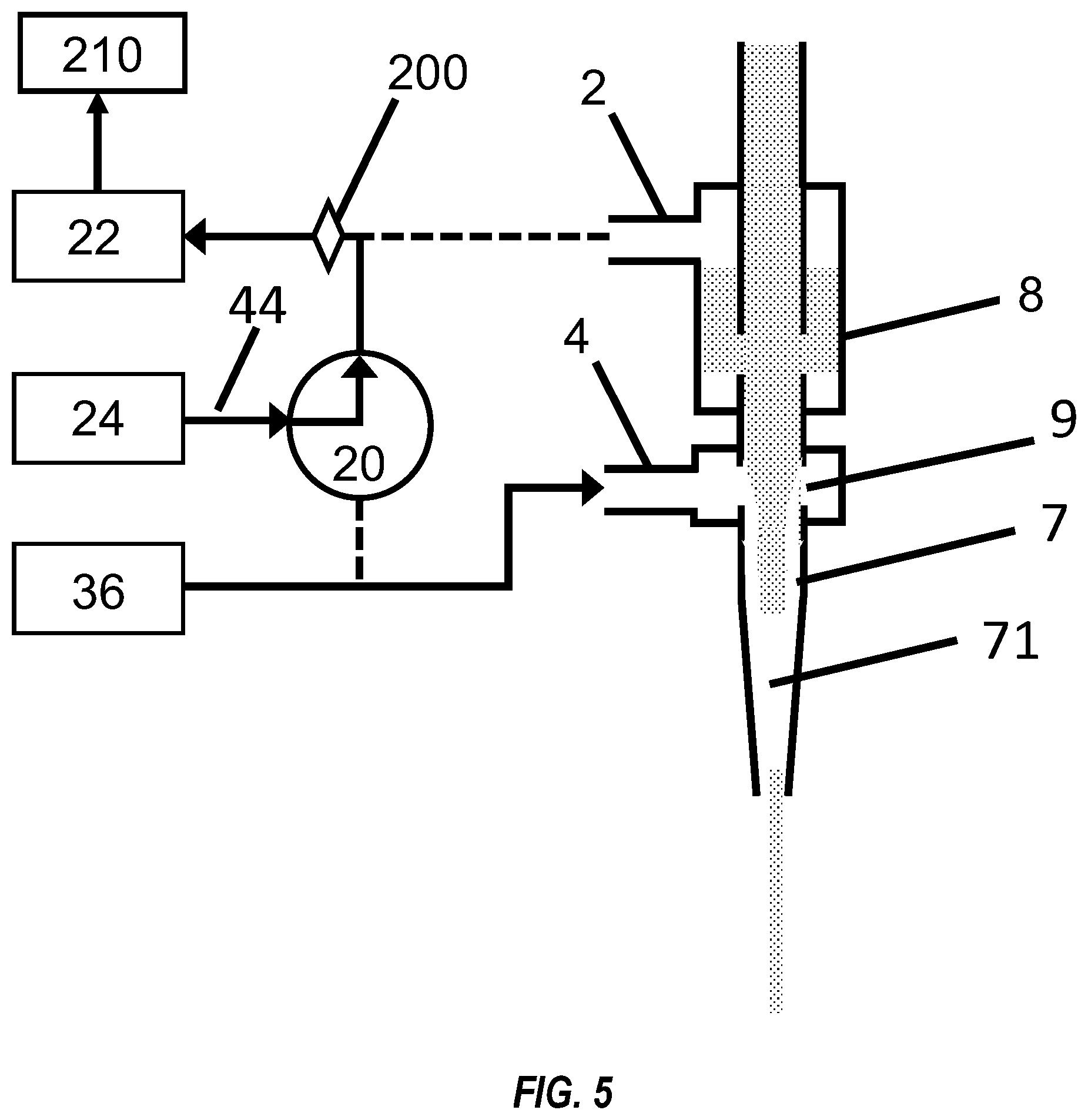
FIG. 5 is a schematic of the flows in the device of FIG. 1 when printing is resumed after transient shuttering.
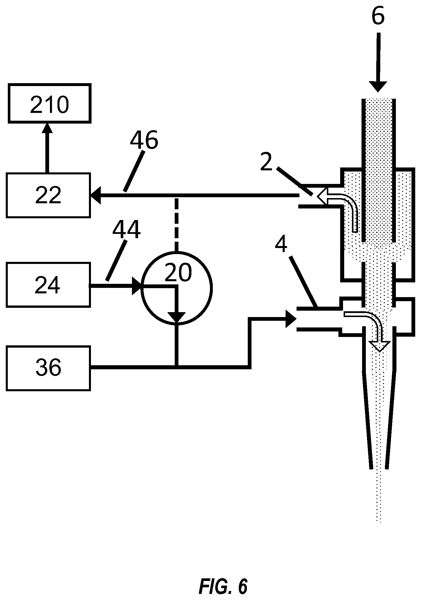
FIG. 6 is a schematic of the flows in the device of FIG. 1 during partial shuttering (i.e. partial diversion).
FIG. 7 is a schematic of the velocity distribution in the aerosol flow in the device of FIG. 1.
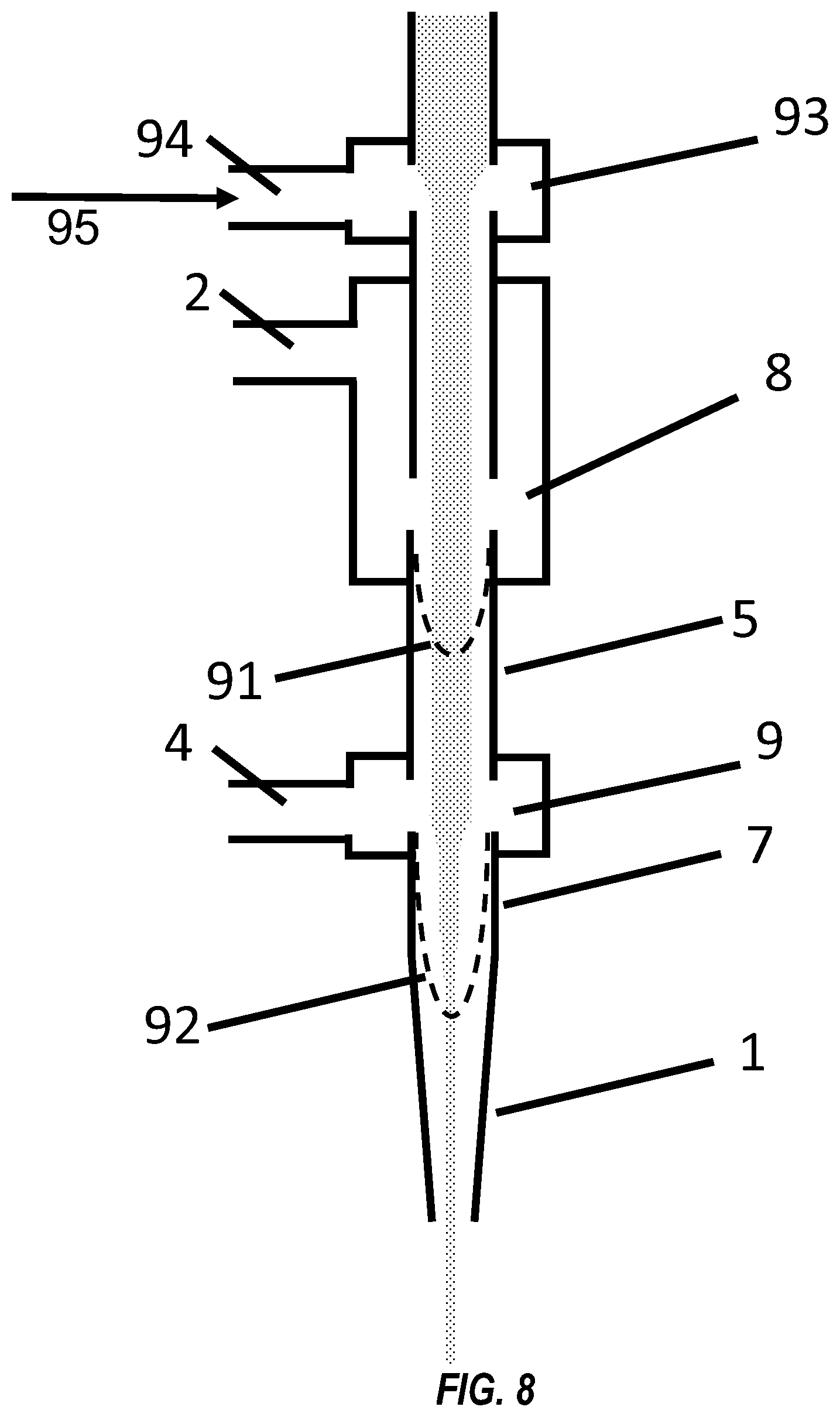
FIG. 8 is a schematic of the velocity distribution in the aerosol flow in a device similar to that of FIG. 1, but which employs use of a pre-sheath gas.
DETAILED DESCRIPTION OF THE INVENTION
Embodiments of the present invention are apparatuses and methods for rapid shuttering of an aerosol stream or a sheathed aerosol stream, which can be applied to, but are not limited to, processes requiring coordinated shuttering of a fluid, such as for aerosol-based printing of discrete structures for directly written electronics, for aerosol delivery applications, or for various three-dimensional printing applications. The fluid stream may comprise solid particles in liquid suspension, liquid droplets, or a combination thereof. As used herein, the terms "droplet" or "particle", used interchangeably, mean liquid droplets, liquids with solid particles in suspension, or mixtures thereof. The present invention provides methods and apparatuses to enable controlled full or partial on-and-off deposition of ink droplets in an aerosol stream for printing arbitrary patterns on a surface with Aerosol Jet.RTM. technology.
In one or more embodiments of the present invention, an internal shutter is incorporated into an apparatus for high-resolution, maskless deposition of liquid ink using aerodynamic focusing. This apparatus typically comprises an atomizer for generating a mist by atomizing the liquid into fine microdroplets. The atomized mist is then transported by a carrier gas flow to a deposition nozzle for directing and focusing the aerosol mist stream. The apparatus also preferably comprises a control module for automated control of process parameters and a motion control module that drives relative motions of the substrate with respect to the deposition nozzle. Aerosolization of liquid inks can be accomplished with a number of methods, including using an ultrasonic atomizer or pneumatic atomizer. The aerosol stream is focused using the Aerosol Jet.RTM. deposition nozzle with a converging channel and an annular, co-flowing sheath gas which wraps the aerosol stream to protect the channel wall from direct contact with liquid ink droplets and to focus the aerosol stream into smaller diameter when accelerated through the converging nozzle channel. The aerosol stream surrounded by the sheath gas exits the deposition nozzle and impacts the substrate. The high-speed jet flow of the collimated aerosol stream with sheath gas enables high-precision material deposition with an extended standoff distance for direct-write printing. The Aerosol Jet.RTM. deposition head is capable of focusing an aerosol stream to as small as one-tenth the size of the nozzle orifice. Ink patterning can be accomplished by attaching the substrate to a platen with computer-controlled motion while the deposition nozzle is fixed. Alternatively, the deposition head can move under computer control while the substrate position remains fixed, or both the deposition head and substrate can move relatively under computer control. The aerosolized liquid used in the Aerosol Jet process consists of any liquid ink material including, but not limited to, liquid molecular precursors for a particular material, particulate suspensions, or some combination of precursor and particulates. Fine lines of width less than 10 .mu.m have been printed using the Aerosol Jet.RTM. system and the internal pneumatic shutter apparatus of the present invention.
A print head comprising an embodiment of the internal shuttering of the present invention is shown in FIG. 1. The print head comprises internal mist switching chamber 8. Aerosol stream 6 generated by an atomizer preferably enters through the top of the print head and moves in the direction indicated by the arrow. The mist flow rate M preferably remains steady during both printing and diverting of aerosol stream 6. During printing aerosol stream 6 preferably enters the print head from the top and travels through upper mist tube 26 to mist switching chamber 8, and then through the middle mist tube 5 to sheath-boost chamber 9, where aerosol stream 6 is surrounded by sheath gas flow 32 from the sheath mass flow controller 36, through the lower mist tube 7 to the deposition nozzle 1 and exits the nozzle tip 10. Sheath gas flow 32 with flow rate S, which is preferably delivered from a gas supply such as a compressed air cylinder and controlled via mass flow controller 36, is preferably introduced into the print head through sheath-boost inlet 4 to form a preferably axisymmetric, annular, co-flowing sheath wrapping around the aerosol stream in sheath-boost chamber 9, thus protecting the walls of lower mist tube 7 and deposition nozzle 1 from impaction by droplets of the aerosol. The sheath gas also serves to focus the aerosol stream, enabling deposition of small diameter features. During printing, three-way valve 20 is configured so that boost gas flow 44 from boost mass flow controller 24 does not enter sheath-boost chamber 9, but instead bypasses the print head and exits the system through exhaust mass flow controller 22.
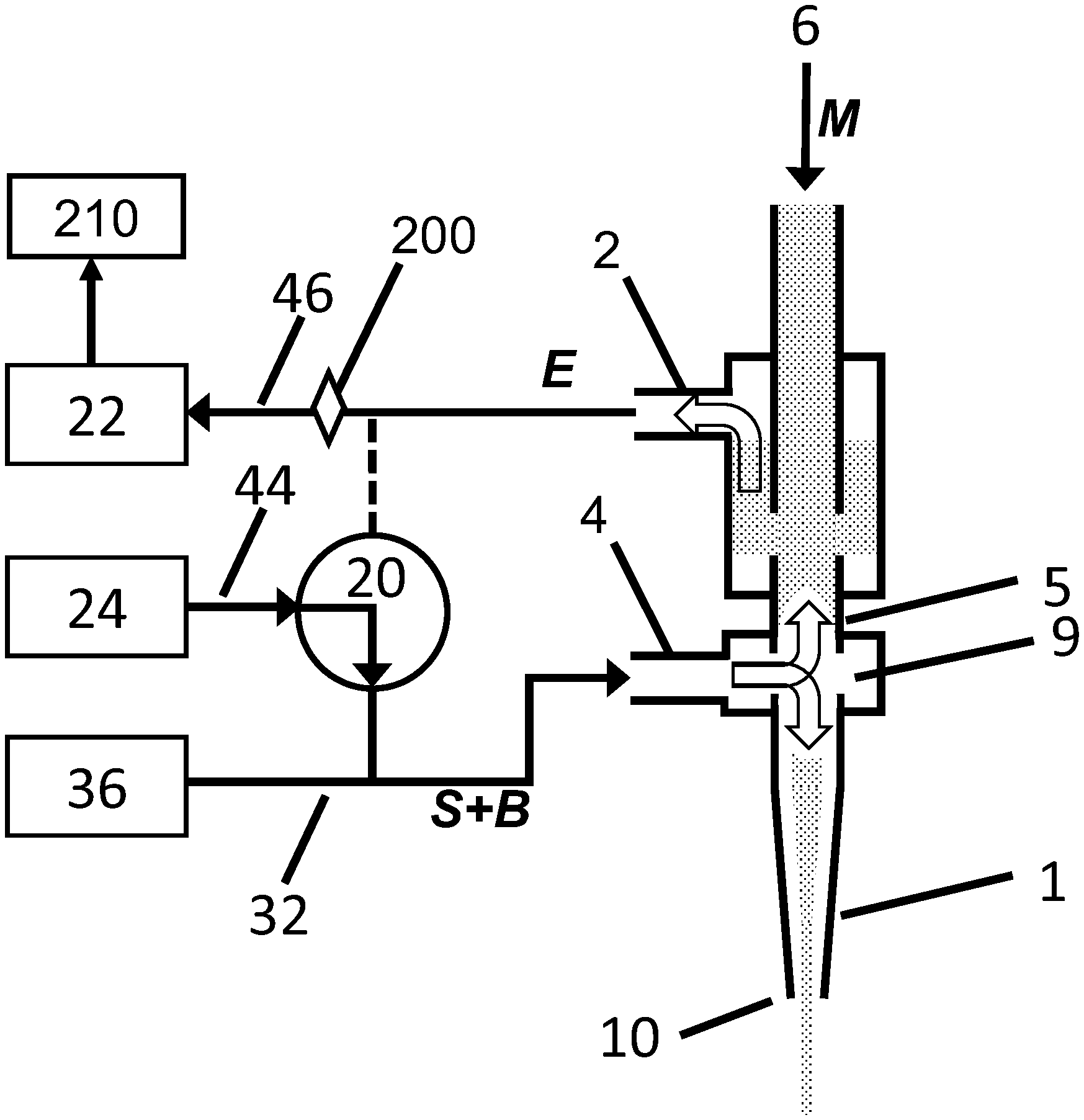
As shown in FIG. 2, to accomplish shuttering or diversion of the aerosol flow, three-way valve 20 switches such that boost gas flow 44 having a flow velocity B, which is preferably supplied by a gas supply such as a compressed air cylinder and controlled by mass flow controller 24, combines with sheath gas flow 32 and enters the print head through sheath-boost inlet 4. Exhaust flow 46 exits the print head through the exhaust outlet 2 and diverts the aerosol stream 6 away from middle mist tube 5.
When the combined sheath gas flow 32 and boost gas flow 44 enter sheath-boost chamber 9 through sheath-boost inlet 4, they are split into equal or unequal flows in both the upwards (i.e. in a direction opposite to the flow direction of aerosol stream 6) and downwards directions. When a portion of the combined sheath and boost gas flows travels downward towards nozzle tip 10, it propels the aerosol particles between sheath-boost chamber 9 and deposition nozzle tip 10 out through nozzle tip 10.
After the residual aerosol is cleared from the nozzle tip 10, which can take approximately 5-50 milliseconds (depending on the gas flow rates), the printing shuts off, as shown in FIG. 3. While the aerosol stream in the deposition nozzle 1 is being cleared, the upwards portion of the combined boost and sheath gas flow pushes the residual aerosol stream 6 in middle mist tube 5 up towards exhaust outlet 2. Aerosol stream 6 continues to exit upper mist tube 26 but is diverted out exhaust outlet 2. The net outward exhaust flow from exhaust outlet 2, having flow rate E, is preferably driven by vacuum pump 210, preferably operated at approximately seven pounds vacuum, and controlled by exhaust mass flow controller 22. As used throughout the specification and claims, the term "vacuum pump" means a vacuum pump or any other suction producing apparatus. Because flow rate control devices typically contain valves with small orifices or small channels which can be contaminated or even damaged if the ink-laden exhaust flow passes through them, mist particle filter or other filtration mechanism 200 is preferably implemented between exhaust outlet 2 and exhaust mass flow controller 22.
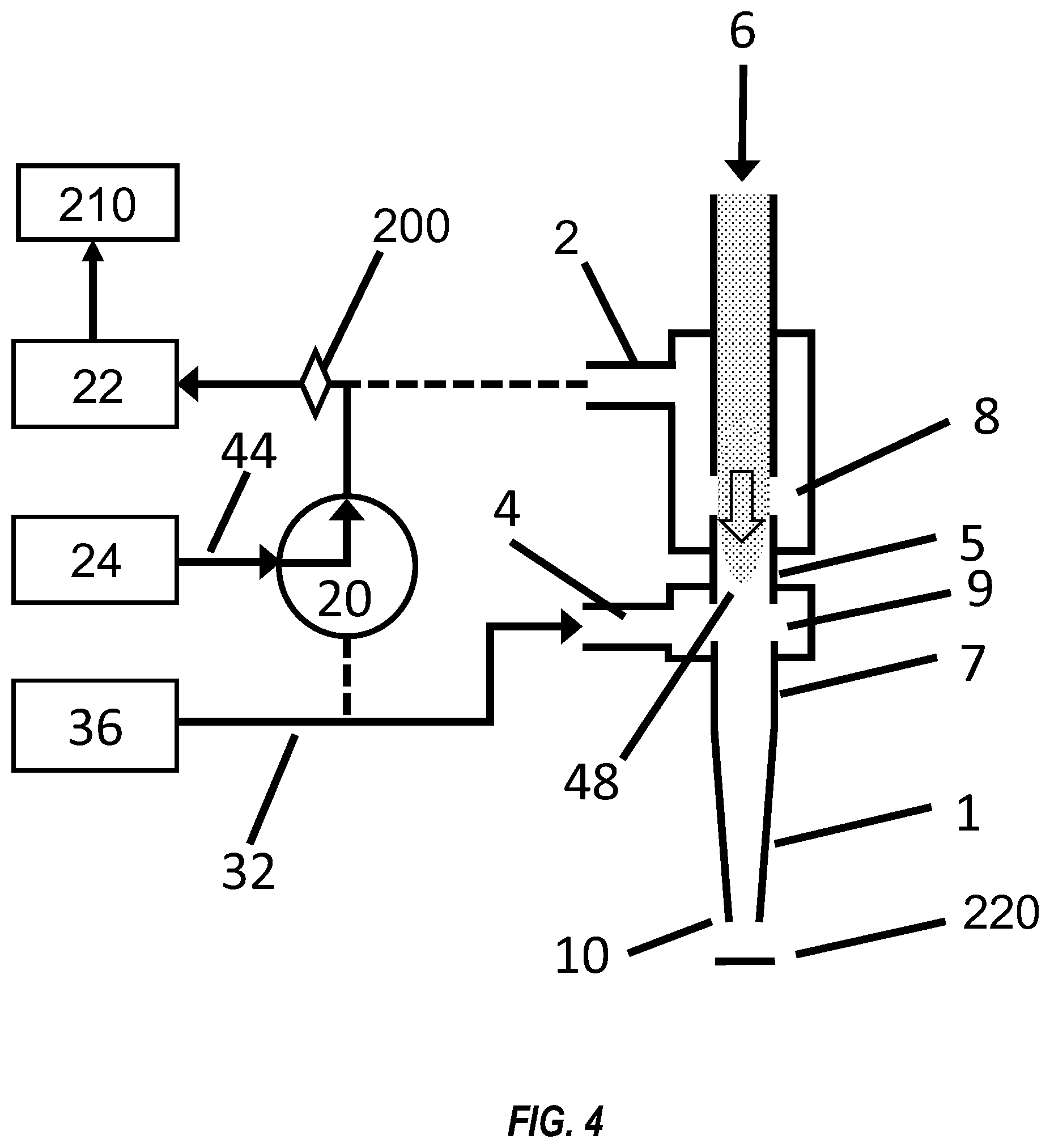
When the print configuration is resumed, as shown in FIG. 4, the boost gas and exhaust flows do not pass thru the head, and no upwards flow occurs in middle mist tube 5. In the printing configuration, three-way valve 20 is switched such that boost gas flow 44 bypasses the print head. Sheath mass flow controller 36 continues to supply sheath gas flow 32 to sheath-boost inlet 4. The leading edge of aerosol stream 6 resumes a substantially parabolic flow profile 48 down the print head through mist switching chamber 8, first filling middle mist tube 5, and is then surrounded by sheath gas flow 32, after which the co-flowing aerosol stream 6 and sheath gas flows into the deposition nozzle 1 and finally through the nozzle tip 10. When switching from diverting to printing, aerosol stream 6 passes downward through middle mist tube 5, sheath-boost chamber 9, and deposition nozzle 1 before printing will resume. Small lengths and inner diameters for middle mist tube 5 and lower mist tube 7 are preferable to minimize on/off delays. Switching from diverting to printing functions can occur in as little as 10 milliseconds. Switching from printing to diverting can occur in as little as 5 milliseconds, depending on the nozzle or orifice size, boost flow rate, and sheath flow rate.
Mist switching chamber 8 is preferably located as close to nozzle tip 10 as possible to minimize mist flow response time that correlates with the distance aerosol stream 6 has to travel from mist switching chamber 8 to deposition nozzle tip 10. Similarly, the inner diameters of middle mist tube 5, lower mist tube 7, and deposition nozzle 1 are preferably minimized to increase the velocity of the flow, thereby minimizing the mist transit time from mist switching chamber 8 to the outlet of nozzle tip 10. The flow control of the various flows in the system preferably utilizes mass flow controllers as shown to provide precise flows over the long durations of production runs. Alternatively, orifice-type or rotameter flow controls may be preferable for low-cost applications. Furthermore, to maximize the stability of the system and minimize transition times, M and S are preferably each maintained approximately constant at all times, including during both printing and diverting modes and during shuttering transitions.
To minimize shuttering transition times, it is preferable that the pressure in the print head remains constant during printing, shuttering, and transitions between the two. If the flow in nozzle channel 3 has a flow rate N, then preferably M+S+B=E+N. In print mode, B=0 and E=0, so N=M+S. In addition, the pressure inside sheath-boost chamber 9 is preferably maintained constant to minimize shuttering transition times. Because this pressure is determined by the back pressure from the total flow through nozzle tip 10, it is preferable that the net flow through nozzle tip 10 remains the same during all operational modes and transitions between them. Thus, during complete shuttering, E and S are preferably chosen so that N=M+S. During shuttering, E=M+f(B+S), where f is the fraction of the combined boost and sheath flows that is diverted upward, and N=M+S=(1-f)(B+S). If the flow in the device satisfies these conditions (i.e. the flow rate M of mist in nozzle channel 3 during printing is substantially replaced by (1-t)B-fS during diversion such that the total flow rate N of whatever is exiting the nozzle is constant), the sheath gas flow streamlines in nozzle channel 3 are preferably substantially undisturbed by directing boost flow B through the head to disable printing.
For a completely diverted flow, solving these equations yields E=B; thus mass flow controllers 22 and 24 preferably are set such that E=B for complete flow diversion. To ensure complete internal shuttering or diversion of the aerosol flow, the rate B of boost gas flow 44 is preferably greater than flow rate M of aerosol stream 6 flow rate; preferably approximately 1.2-2 times the aerosol stream flow rate M; and more preferably B equals approximately 2M for robust, complete mist switching in most applications.
In one theoretical example, if aerosol stream 6 has a flow rate of M=50 sccm, and sheath gas flow 32 has a flow rate S of 55 sccm, during printing the flow rate in nozzle channel 3 (and thus exiting nozzle tip 10) is M+S=105 sccm. In this mode, since the boost gas flow 44 does not enter the print head, and nothing exits exhaust outlet 2, B=E=0 (even though in actuality, as described above, to maintain stability mass flow controller 44 is set to provide 100 sccm of flow that is diverted by three-way valve 20 to flow directly to mass flow controller 42, which is also set to pass 100 sccm of flow to vacuum pump 210). When complete diversion is desired, the rate B of boost gas flow 44 (and, as derived above, rate E of exhaust flow 46) is preferably selected so that B=E=2M=100 sccm for mist diverting. During diverting or shuttering of the aerosol stream, the combined sheath and boost flows having a total flow rate of S+B=155 sccm split within sheath-boost chamber 9 such that effectively N=105 sccm of the combined flow flows downwards through lower mist tube 7 and deposition nozzle 1, replacing aerosol stream 6 (and sheath flow 32) that are now being diverted in mist switching chamber 8. Because E is set to 100 sccm in mass flow controller 22, 50 sccm of the split combined flow flows upwards, flushing the residual aerosol stream 6 from the middle mist tube 5 and into the switching chamber 8 where it combines with the diverted aerosol flow. Therefore, exhaust flow 46 exiting exhaust outlet 2 will be equal to the aerosol stream flow rate M plus the upward portion of the boost gas flow rate, or E=100 sccm. The total flows into the printhead (M+B+S=205 sccm) equals the total flows out of the printhead (N+E=205 sccm). Typically, balanced flows allow for a constant pressure inside the sheath-boost chamber 9, which leads to complete turning on and off (i.e. shuttering of) the aerosol stream with minimized shuttering times.
Hybrid Shuttering
Internal pneumatic shuttering by diverting the aerosol stream to exhaust outlet 2 can occur for long periods of time without adverse effects, contrary to mechanical shuttering, where ink accumulation on a mechanical shutter inserted to block the aerosol flow can dislodge and foul the substrate or aerodynamic surfaces of the print head. The internal pneumatic shutter can be used alone or in combination with another shuttering technique, such as mechanical shuttering, to take advantage of the faster response of the mechanical shuttering while minimizing the ink accumulation on the top of the mechanical shutter arm. In this embodiment, when stopping the printing the mechanical shutter is activated to block the aerosol flow. Pneumatic shuttering as described above diverts the ink away from mechanical shutter 220 for the majority of the shuttering duration, thus reducing ink buildup on the mechanical shutter. Because the pneumatic shutter activates more slowly when compared to the faster mechanical shutter, the pneumatic shutter is preferably triggered at a time such that the faster mechanical shutter closes first, and the pneumatic shutter closes as soon as possible thereafter. To resume printing, the pneumatic shutter is preferably opened first to allow the output to stabilize, then mechanical shutter 220 is opened. Although a mechanical shutter can be located anywhere within the print head, or even external to the deposition nozzle, mechanical impact shuttering preferably occurs close to where the aerosol stream exits the deposition nozzle.
Transient Shuttering
In an alternative embodiment of the current invention, the internal shutter can be used as a transient shutter, for which diversion of the aerosol flow occurs for a short enough period that the aerosol distribution in the print head does not have time to equilibrate. FIG. 2 shows the aerosol distribution immediately after switching three-way valve 20 to add boost gas flow 44 to sheath-boost input 4 and pull exhaust flow 46 from exhaust port 2. The gap in the aerosol created in sheath-boost chamber 9 expands downward thru lower mist tu
References
-
3dprint.com/51566/carbon3d-clip-3d-printing
-
nano-di.com/3d-printer
-
nordson.com/en/divisions/asymtek/products/fluid-dispensing-systems?nor_division_facet_b=f65ab511444f4ce087bae3fb19491a82
-
nscrypt.com/3d-printing
-
nscrypt.com/3d-printing
-
stratasys.com/3d-printers/technologies/fdm-technology
-
-
tsi.com
-
en.wikipedia.org/wiki/Continuous_Liquid_Interface_Production
-
en.wikipedia.org/wiki/Selective_laser_sintering
-
en/wikipedia/org/wiki/Stereolithography
D00000
D00001
D00002
D00003
D00004
D00005
D00006
D00007
D00008
XML
uspto.report is an independent third-party trademark research tool that is not affiliated, endorsed, or sponsored by the United States Patent and Trademark Office (USPTO) or any other governmental organization. The information provided by uspto.report is based on publicly available data at the time of writing and is intended for informational purposes only.
While we strive to provide accurate and up-to-date information, we do not guarantee the accuracy, completeness, reliability, or suitability of the information displayed on this site. The use of this site is at your own risk. Any reliance you place on such information is therefore strictly at your own risk.
All official trademark data, including owner information, should be verified by visiting the official USPTO website at www.uspto.gov. This site is not intended to replace professional legal advice and should not be used as a substitute for consulting with a legal professional who is knowledgeable about trademark law.