Systems and methods for time-based athletic activity measurement and display
Meschter , et al.
U.S. patent number 10,632,343 [Application Number 16/376,123] was granted by the patent office on 2020-04-28 for systems and methods for time-based athletic activity measurement and display. This patent grant is currently assigned to NIKE, Inc.. The grantee listed for this patent is NIKE, Inc.. Invention is credited to James Meschter, James Molyneux, Aaron B. Weast.


View All Diagrams
| United States Patent | 10,632,343 |
| Meschter , et al. | April 28, 2020 |
Systems and methods for time-based athletic activity measurement and display
Abstract
An athletic parameter measurement device worn by an athlete during an athletic activity session includes a housing which attaches to the athlete, a display, a processor associated with the display, and an athletic parameter measurement sensor. During the athletic activity, the device detects, using the sensor, a vertical jump height of the athlete, and displays, during the performance of the athletic activity session, a representation of the vertical jump height on the display.
| Inventors: | Meschter; James (Portland, OR), Molyneux; James (Portland, OR), Weast; Aaron B. (Portland, OR) | ||||||||||
|---|---|---|---|---|---|---|---|---|---|---|---|
| Applicant: |
|
||||||||||
| Assignee: | NIKE, Inc. (Beaverton,
OR) |
||||||||||
| Family ID: | 45094773 | ||||||||||
| Appl. No.: | 16/376,123 | ||||||||||
| Filed: | April 5, 2019 |
Prior Publication Data
| Document Identifier | Publication Date | |
|---|---|---|
| US 20190232109 A1 | Aug 1, 2019 | |
Related U.S. Patent Documents
| Application Number | Filing Date | Patent Number | Issue Date | ||
|---|---|---|---|---|---|
| 15994517 | May 13, 2018 | 10293209 | |||
| 15693753 | Jul 3, 2018 | 10010752 | |||
| 15223188 | Sep 12, 2017 | 9757619 | |||
| 14722695 | Aug 30, 2016 | 9429411 | |||
| 14478203 | Jul 12, 2016 | 9389057 | |||
| 13293653 | Sep 9, 2014 | 8831407 | |||
| 61412285 | Nov 10, 2010 | ||||
| Current U.S. Class: | 1/1 |
| Current CPC Class: | G16H 50/20 (20180101); G16H 40/63 (20180101); H04N 7/181 (20130101); G09B 5/02 (20130101); G16H 40/67 (20180101); G06F 19/3481 (20130101); A63B 24/0062 (20130101); G01P 15/09 (20130101); G01B 5/02 (20130101); H04N 5/9205 (20130101); G06F 19/00 (20130101); G16H 20/30 (20180101) |
| Current International Class: | A63B 24/00 (20060101); G16H 40/63 (20180101); H04N 5/92 (20060101); H04N 7/18 (20060101); G01B 5/02 (20060101); G09B 5/02 (20060101); G16H 20/30 (20180101); G16H 50/20 (20180101); G01P 15/09 (20060101) |
References Cited [Referenced By]
U.S. Patent Documents
| 3270564 | September 1966 | Evans |
| 4372558 | February 1983 | Shimamoto et al. |
| 4373651 | February 1983 | Fanslow |
| 4496148 | January 1985 | Morstain et al. |
| 4518267 | May 1985 | Hepp |
| 4578969 | April 1986 | Larson |
| 4647918 | March 1987 | Goforth |
| 4664378 | May 1987 | Van Auken |
| 4703445 | October 1987 | Dassler |
| 4745930 | May 1988 | Confer |
| 4814661 | March 1989 | Ratzlaff et al. |
| 4866412 | September 1989 | Rzepczynski |
| 4890111 | December 1989 | Nicolet et al. |
| 4980871 | December 1990 | Sieber et al. |
| 5010774 | April 1991 | Kikuo et al. |
| 5033291 | July 1991 | Podoloff et al. |
| 5047952 | September 1991 | Kramer et al. |
| 5050962 | September 1991 | Monnier et al. |
| 5149084 | September 1992 | Dalebout et al. |
| 5150536 | September 1992 | Strong |
| 5154960 | October 1992 | Mucci et al. |
| 5249967 | October 1993 | O'Leary et al. |
| 5270433 | December 1993 | Klauck et al. |
| 5303131 | April 1994 | Wu |
| 5323650 | June 1994 | Fullen et al. |
| 5363297 | November 1994 | Larson et al. |
| 5373651 | December 1994 | Wood |
| 5374821 | December 1994 | Muhs et al. |
| 5393651 | February 1995 | Hoshi |
| 5408873 | April 1995 | Schmidt et al. |
| 5419562 | May 1995 | Cromarty |
| 5422521 | June 1995 | Neer et al. |
| 5444462 | August 1995 | Wambach |
| 5446701 | August 1995 | Utke et al. |
| 5471405 | November 1995 | Marsh |
| 5500635 | March 1996 | Mott |
| 5513854 | May 1996 | Daver |
| 5636146 | June 1997 | Flentov et al. |
| 5636378 | June 1997 | Griffith |
| 5638300 | June 1997 | Johnson |
| 5644858 | July 1997 | Bemis |
| 5655316 | August 1997 | Huang |
| 5694514 | December 1997 | Evans et al. |
| 5697791 | December 1997 | Nashner et al. |
| 5702323 | December 1997 | Poulton |
| 5714706 | February 1998 | Nakada et al. |
| 5720200 | February 1998 | Anderson et al. |
| 5724265 | March 1998 | Hutchings |
| 5764786 | June 1998 | Kuwashima et al. |
| 5785666 | July 1998 | Costello et al. |
| 5812142 | September 1998 | Small et al. |
| 5813142 | September 1998 | Demon |
| 5813406 | September 1998 | Kramer et al. |
| 5825327 | October 1998 | Krasner |
| 5844861 | December 1998 | Maurer |
| 5889464 | March 1999 | Huang |
| 5903454 | May 1999 | Hoffberg et al. |
| 5907819 | May 1999 | Johnson |
| 5913727 | June 1999 | Ahdoot |
| 5929332 | July 1999 | Brown |
| 5960380 | September 1999 | Flentov et al. |
| 5963891 | October 1999 | Walker et al. |
| 5982352 | November 1999 | Pryor |
| 6002982 | December 1999 | Fry |
| 6013007 | January 2000 | Root et al. |
| 6017128 | January 2000 | Goldston et al. |
| 6018705 | January 2000 | Gaudet et al. |
| 6042492 | March 2000 | Baum |
| 6050962 | April 2000 | Kramer et al. |
| 6066075 | May 2000 | Poulton |
| 6073086 | June 2000 | Marinelli |
| 6081750 | June 2000 | Hoffberg et al. |
| 6122340 | September 2000 | Darley et al. |
| 6122846 | September 2000 | Gray et al. |
| 6141041 | October 2000 | Carlbom et al. |
| 6148262 | November 2000 | Fry |
| 6148271 | November 2000 | Marinelli |
| 6148280 | November 2000 | Kramer |
| 6151563 | November 2000 | Marinelli |
| 6157898 | December 2000 | Marinelli |
| 6174294 | January 2001 | Crabb et al. |
| 6195921 | March 2001 | Truong |
| 6198394 | March 2001 | Jacobsen et al. |
| 6204813 | March 2001 | Wadell et al. |
| 6226577 | May 2001 | Yeo |
| 6266623 | July 2001 | Vock et al. |
| 6270433 | August 2001 | Orenstein et al. |
| 6287200 | September 2001 | Sharma |
| 6298314 | October 2001 | Blackadar et al. |
| 6308565 | October 2001 | French et al. |
| 6320173 | November 2001 | Vock et al. |
| 6330757 | December 2001 | Russell |
| 6336365 | January 2002 | Blackadar et al. |
| 6336891 | January 2002 | Fedrigon et al. |
| 6356856 | March 2002 | Damen et al. |
| 6357147 | March 2002 | Darley et al. |
| 6360597 | March 2002 | Hubbard, Jr. |
| 6418181 | July 2002 | Nissila |
| 6426490 | July 2002 | Storz |
| 6428490 | August 2002 | Kramer et al. |
| 6430843 | August 2002 | Potter et al. |
| 6430997 | August 2002 | French et al. |
| 6496787 | December 2002 | Flentov et al. |
| 6496952 | December 2002 | Osada et al. |
| 6498994 | December 2002 | Vock et al. |
| 6515284 | February 2003 | Walle et al. |
| 6516284 | February 2003 | Flentov et al. |
| 6536139 | March 2003 | Darley et al. |
| 6539336 | March 2003 | Vock et al. |
| 6544858 | April 2003 | Beekman et al. |
| 6560903 | May 2003 | Darley |
| 6567038 | May 2003 | Granot et al. |
| 6567116 | May 2003 | Aman et al. |
| 6578291 | June 2003 | Hirsch et al. |
| 6582330 | June 2003 | Rehkemper et al. |
| 6611789 | August 2003 | Darley |
| 6620057 | September 2003 | Pirritano et al. |
| 6640144 | October 2003 | Huang et al. |
| 6656042 | December 2003 | Reiss et al. |
| 6671390 | December 2003 | Barbour et al. |
| 6707487 | March 2004 | Aman et al. |
| 6710713 | March 2004 | Russo |
| 6718200 | April 2004 | Marmaropoulos et al. |
| 6748462 | June 2004 | Dubil et al. |
| 6778973 | August 2004 | Harlan |
| 6784826 | August 2004 | Kane et al. |
| 6785579 | August 2004 | Huang et al. |
| 6785805 | August 2004 | House et al. |
| 6808462 | October 2004 | Snyder et al. |
| 6829512 | December 2004 | Huang et al. |
| 6831603 | December 2004 | Menache |
| 6836744 | December 2004 | Asphahani et al. |
| 6876947 | April 2005 | Darley et al. |
| 6882897 | April 2005 | Fernandez |
| 6885971 | April 2005 | Vock et al. |
| 6889282 | May 2005 | Schollenberger |
| 6892216 | May 2005 | Coburn, II et al. |
| 6909420 | June 2005 | Nicolas et al. |
| 6922664 | July 2005 | Fernandez et al. |
| 6932698 | August 2005 | Sprogis |
| 6959259 | October 2005 | Vock et al. |
| 6963818 | November 2005 | Flentov et al. |
| 6978320 | December 2005 | Nonaka |
| 7005970 | February 2006 | Hodsdon et al. |
| 7030861 | April 2006 | Westerman et al. |
| 7040998 | May 2006 | Jolliffe et al. |
| 7045151 | May 2006 | Trant |
| 7046151 | May 2006 | Dundon |
| 7054784 | May 2006 | Flentov et al. |
| 7057551 | June 2006 | Vogt |
| 7070571 | July 2006 | Kramer et al. |
| 7072789 | July 2006 | Vock et al. |
| 7091863 | August 2006 | Ravet |
| 7092846 | August 2006 | Vock et al. |
| 7139582 | November 2006 | Couronne et al. |
| 7152343 | December 2006 | Whatley |
| 7162392 | January 2007 | Vock et al. |
| 7171331 | January 2007 | Vock et al. |
| 7174277 | February 2007 | Vock et al. |
| 7200517 | April 2007 | Darley et al. |
| 7245898 | July 2007 | Van Bosch et al. |
| 7273431 | September 2007 | DeVall |
| 7277021 | October 2007 | Beebe et al. |
| 7283647 | October 2007 | McNitt |
| 7304580 | December 2007 | Sullivan et al. |
| 7310895 | December 2007 | Whittlesey et al. |
| 7321330 | January 2008 | Sajima |
| 7383728 | June 2008 | Noble et al. |
| 7391886 | June 2008 | Clark et al. |
| RE40474 | September 2008 | Quellais et al. |
| 7426873 | September 2008 | Kholwadwala et al. |
| 7428471 | September 2008 | Darley et al. |
| 7433805 | October 2008 | Vock et al. |
| 7457724 | November 2008 | Vock et al. |
| 7487045 | February 2009 | Vieira |
| 7497037 | March 2009 | Vick et al. |
| 7498856 | March 2009 | Lin et al. |
| 7498956 | March 2009 | Baier et al. |
| 7513852 | April 2009 | Wilkins et al. |
| 7522970 | April 2009 | Fernandez |
| 7552549 | June 2009 | Whittlesey et al. |
| 7556589 | July 2009 | Stearns et al. |
| 7579946 | August 2009 | Case, Jr. |
| 7596891 | October 2009 | Carnes et al. |
| 7602301 | October 2009 | Stirling et al. |
| 7607243 | October 2009 | Bemer, Jr. et al. |
| 7617068 | November 2009 | Tadin et al. |
| 7620466 | November 2009 | Neale et al. |
| 7623987 | November 2009 | Vock et al. |
| 7625314 | December 2009 | Ungari et al. |
| 7627451 | December 2009 | Vock et al. |
| 7634379 | December 2009 | Noble |
| 7641592 | January 2010 | Roche |
| 7651442 | January 2010 | Carlson |
| 7658694 | February 2010 | Ungari |
| 7670263 | March 2010 | Ellis et al. |
| 7698830 | April 2010 | Townsend et al. |
| 7726206 | June 2010 | Terrafranca, Jr. et al. |
| 7739076 | June 2010 | Vock et al. |
| 7758523 | July 2010 | Collings et al. |
| 7771320 | August 2010 | Riley et al. |
| 7791808 | September 2010 | French et al. |
| 7805150 | September 2010 | Graham et al. |
| 7816632 | October 2010 | Bourke, III et al. |
| 7840378 | November 2010 | Vock et al. |
| 7901325 | March 2011 | Henderson |
| 7905815 | March 2011 | Ellis et al. |
| 7909737 | March 2011 | Ellis et al. |
| 7921716 | April 2011 | Morris Bamberg et al. |
| 7927253 | April 2011 | Vincent et al. |
| 7934983 | May 2011 | Eisner |
| 7997007 | August 2011 | Sanabria-Hernandez |
| 8002645 | August 2011 | Savarese et al. |
| 8054176 | November 2011 | Karjalainen |
| 8056268 | November 2011 | DiBenedetto et al. |
| 8061061 | November 2011 | Rivas |
| 8066514 | November 2011 | Clarke |
| 8070620 | December 2011 | Rankin |
| 8099258 | January 2012 | Alten et al. |
| 8131498 | March 2012 | McCauley |
| 8142267 | March 2012 | Adams |
| 8172722 | May 2012 | Molyneux et al. |
| 8212158 | July 2012 | Wiest |
| 8221290 | July 2012 | Vincent et al. |
| 8251930 | August 2012 | Ido |
| 8253586 | August 2012 | Matak |
| 8257189 | September 2012 | Koudele et al. |
| 8291618 | October 2012 | Ellis |
| 8333643 | December 2012 | Eisner |
| 8337212 | December 2012 | Prstojevich |
| 8353791 | January 2013 | Holthouse et al. |
| 8360904 | January 2013 | Oleson et al. |
| 8467979 | June 2013 | Sobolewski |
| 8474153 | July 2013 | Brie et al. |
| 8484654 | July 2013 | Graham et al. |
| 8676541 | March 2014 | Schrock et al. |
| 8739639 | June 2014 | Owings et al. |
| 8784274 | July 2014 | Chuang |
| 8831407 | September 2014 | Meschter et al. |
| 8860584 | October 2014 | Matak |
| 9389057 | July 2016 | Meschter et al. |
| 9429411 | August 2016 | Meschter et al. |
| 9757619 | September 2017 | Meschter |
| 2001/0054043 | December 2001 | Harlan |
| 2002/0035184 | March 2002 | Plaver et al. |
| 2002/0134153 | September 2002 | Grenlund |
| 2002/0170193 | November 2002 | Townsend et al. |
| 2003/0009308 | January 2003 | Kirtley |
| 2003/0049590 | March 2003 | Feldbau |
| 2003/0054327 | March 2003 | Evensen |
| 2003/0097878 | May 2003 | Farringdon et al. |
| 2003/0148762 | August 2003 | Noe |
| 2003/0163287 | August 2003 | Vock et al. |
| 2003/0207718 | November 2003 | Perlmutter |
| 2004/0006680 | January 2004 | Duncan |
| 2004/0125013 | July 2004 | Haselsteiner et al. |
| 2004/0154190 | August 2004 | Munster |
| 2004/0215413 | October 2004 | Weldum et al. |
| 2004/0218317 | November 2004 | Kawazu et al. |
| 2004/0226192 | November 2004 | Geer et al. |
| 2005/0011085 | January 2005 | Swigart et al. |
| 2005/0032582 | February 2005 | Mahajan et al. |
| 2005/0046576 | March 2005 | Julian et al. |
| 2005/0106977 | May 2005 | Coulston |
| 2005/0143199 | June 2005 | Saroyan |
| 2005/0162257 | July 2005 | Gonzalez |
| 2005/0176373 | August 2005 | Gilbert et al. |
| 2005/0183292 | August 2005 | DiBenedetto et al. |
| 2005/0187644 | August 2005 | Neale et al. |
| 2005/0188566 | September 2005 | Whittlesey et al. |
| 2005/0221403 | October 2005 | Gazenko |
| 2005/0250458 | November 2005 | Graham et al. |
| 2005/0261609 | November 2005 | Collings et al. |
| 2005/0270156 | December 2005 | Ravet |
| 2005/0282633 | December 2005 | Nicolas et al. |
| 2006/0010174 | January 2006 | Nguyen et al. |
| 2006/0017692 | January 2006 | Wehrenberg et al. |
| 2006/0025229 | February 2006 | Mahajan et al. |
| 2006/0025282 | February 2006 | Redmann |
| 2006/0026120 | February 2006 | Carolan et al. |
| 2006/0040244 | February 2006 | Kain |
| 2006/0084850 | April 2006 | Spinner et al. |
| 2006/0091715 | May 2006 | Schmitz et al. |
| 2006/0136173 | June 2006 | Case et al. |
| 2006/0143645 | June 2006 | Vock et al. |
| 2006/0144152 | July 2006 | Cabuz et al. |
| 2006/0148594 | July 2006 | Saintoyant et al. |
| 2006/0178235 | August 2006 | Coughlan et al. |
| 2006/0205569 | September 2006 | Watterson et al. |
| 2006/0217231 | September 2006 | Parks et al. |
| 2006/0226843 | October 2006 | Al-Anbuky et al. |
| 2006/0248749 | November 2006 | Ellis |
| 2006/0262120 | November 2006 | Rosenberg |
| 2007/0006489 | January 2007 | Case et al. |
| 2007/0016091 | January 2007 | Butt et al. |
| 2007/0021269 | January 2007 | Shum |
| 2007/0026421 | February 2007 | Sundberg et al. |
| 2007/0032748 | February 2007 | McNeil et al. |
| 2007/0033838 | February 2007 | Luce et al. |
| 2007/0059675 | March 2007 | Kuenzler et al. |
| 2007/0060408 | March 2007 | Schultz et al. |
| 2007/0060425 | March 2007 | Kuenzler et al. |
| 2007/0063849 | March 2007 | Rosella et al. |
| 2007/0063850 | March 2007 | Devaul et al. |
| 2007/0067885 | March 2007 | Fernandez |
| 2007/0068244 | March 2007 | Billing et al. |
| 2007/0069014 | March 2007 | Heckel et al. |
| 2007/0073178 | March 2007 | Browning et al. |
| 2007/0078324 | April 2007 | Wijisiriwardana |
| 2007/0082389 | April 2007 | Clark et al. |
| 2007/0094890 | May 2007 | Cho et al. |
| 2007/0105629 | May 2007 | Toyama |
| 2007/0118328 | May 2007 | Vock et al. |
| 2007/0135225 | June 2007 | Nieminen et al. |
| 2007/0135243 | June 2007 | LaRue et al. |
| 2007/0143452 | June 2007 | Suenbuel et al. |
| 2007/0149361 | June 2007 | Jung et al. |
| 2007/0152812 | July 2007 | Wong et al. |
| 2007/0156335 | July 2007 | McBride et al. |
| 2007/0173705 | July 2007 | Teller et al. |
| 2007/0178967 | August 2007 | Rosenberg |
| 2007/0179977 | August 2007 | Reed et al. |
| 2007/0187266 | August 2007 | Porter et al. |
| 2007/0191083 | August 2007 | Kuenzler et al. |
| 2007/0207447 | September 2007 | Lamar et al. |
| 2007/0208544 | September 2007 | Kulach et al. |
| 2007/0232455 | October 2007 | Hanoun |
| 2007/0250286 | October 2007 | Duncan et al. |
| 2007/0260421 | November 2007 | Bemer et al. |
| 2007/0283599 | December 2007 | Talbott |
| 2007/0299625 | December 2007 | Englert et al. |
| 2008/0009068 | January 2008 | Georges |
| 2008/0027679 | January 2008 | Shklarski |
| 2008/0028783 | February 2008 | Immel et al. |
| 2008/0031492 | February 2008 | Lanz |
| 2008/0039203 | February 2008 | Ackley et al. |
| 2008/0048616 | February 2008 | Paul et al. |
| 2008/0056508 | March 2008 | Pierce et al. |
| 2008/0060224 | March 2008 | Whittlesey et al. |
| 2008/0061023 | March 2008 | Moor |
| 2008/0066343 | March 2008 | Sanabria-Hernandez |
| 2008/0066560 | March 2008 | Yu et al. |
| 2008/0080626 | April 2008 | Lawrence et al. |
| 2008/0084351 | April 2008 | Englert et al. |
| 2008/0085790 | April 2008 | Englert |
| 2008/0088303 | April 2008 | Englert |
| 2008/0090683 | April 2008 | Englert et al. |
| 2008/0090685 | April 2008 | Namie et al. |
| 2008/0104247 | May 2008 | Venkatakrishnan et al. |
| 2008/0109158 | May 2008 | Huhtala et al. |
| 2008/0119479 | May 2008 | Wedge |
| 2008/0127527 | June 2008 | Chen |
| 2008/0134583 | June 2008 | Polus |
| 2008/0165140 | July 2008 | Christie et al. |
| 2008/0172498 | July 2008 | Boucard |
| 2008/0177507 | July 2008 | Mian et al. |
| 2008/0188353 | August 2008 | Vitolo et al. |
| 2008/0200312 | August 2008 | Tagliabue |
| 2008/0203144 | August 2008 | Kim |
| 2008/0218310 | September 2008 | Alten et al. |
| 2008/0221403 | September 2008 | Fernandez |
| 2008/0246629 | October 2008 | Tsui et al. |
| 2008/0249736 | October 2008 | Prstojevich |
| 2008/0255794 | October 2008 | Levine |
| 2008/0258921 | October 2008 | Woo et al. |
| 2008/0259028 | October 2008 | Teepell et al. |
| 2008/0261776 | October 2008 | Skiba |
| 2008/0269644 | October 2008 | Ray |
| 2008/0274755 | November 2008 | Cholkar et al. |
| 2008/0284650 | November 2008 | MacIntosh et al. |
| 2008/0286733 | November 2008 | Claudel et al. |
| 2008/0287832 | November 2008 | Collins et al. |
| 2008/0288200 | November 2008 | Noble |
| 2008/0293023 | November 2008 | Diehl et al. |
| 2008/0297832 | December 2008 | Otsuka |
| 2008/0300914 | December 2008 | Karkanias et al. |
| 2008/0306410 | December 2008 | Kalpaxis et al. |
| 2008/0307899 | December 2008 | Von Lilienfeld-Toal et al. |
| 2008/0316325 | December 2008 | Nakahara |
| 2008/0318679 | December 2008 | Tran et al. |
| 2009/0018691 | January 2009 | Fernandez |
| 2009/0027917 | January 2009 | Chen et al. |
| 2009/0048039 | February 2009 | Holthouse et al. |
| 2009/0048044 | February 2009 | Oleson et al. |
| 2009/0048070 | February 2009 | Vincent et al. |
| 2009/0048538 | February 2009 | Levine et al. |
| 2009/0048918 | February 2009 | Dawson et al. |
| 2009/0050699 | February 2009 | Basar et al. |
| 2009/0061837 | March 2009 | Chaudhri et al. |
| 2009/0069156 | March 2009 | Kurunmaki et al. |
| 2009/0075347 | March 2009 | Cervin et al. |
| 2009/0076341 | March 2009 | James |
| 2009/0090683 | April 2009 | Haghayegh |
| 2009/0105047 | April 2009 | Guidi et al. |
| 2009/0107009 | April 2009 | Bishop et al. |
| 2009/0135001 | May 2009 | Yuk |
| 2009/0137933 | May 2009 | Lieberman et al. |
| 2009/0144084 | June 2009 | Neumaier |
| 2009/0149299 | June 2009 | Tchao et al. |
| 2009/0150178 | June 2009 | Sutton et al. |
| 2009/0152456 | June 2009 | Waid et al. |
| 2009/0153369 | June 2009 | Baier et al. |
| 2009/0153477 | June 2009 | Saenz |
| 2009/0163287 | June 2009 | Vald'Via et al. |
| 2009/0167677 | July 2009 | Kruse et al. |
| 2009/0171614 | July 2009 | Damen |
| 2009/0189982 | July 2009 | Tawiah |
| 2009/0210078 | August 2009 | Crowley |
| 2009/0233770 | September 2009 | Vincent et al. |
| 2009/0235739 | September 2009 | Morris Bamberg et al. |
| 2009/0258710 | October 2009 | Quatrochi et al. |
| 2009/0259566 | October 2009 | White et al. |
| 2009/0262088 | October 2009 | Moll-Carrillo et al. |
| 2009/0293319 | December 2009 | Avni |
| 2009/0297832 | December 2009 | Hatta et al. |
| 2010/0000121 | January 2010 | Brodie et al. |
| 2010/0004566 | January 2010 | Son et al. |
| 2010/0023231 | January 2010 | Allgaier et al. |
| 2010/0023531 | January 2010 | Brisebois et al. |
| 2010/0035688 | February 2010 | Picunko |
| 2010/0053867 | March 2010 | Ellis et al. |
| 2010/0056340 | March 2010 | Ellis et al. |
| 2010/0057951 | March 2010 | Ellis et al. |
| 2010/0059561 | March 2010 | Ellis et al. |
| 2010/0062740 | March 2010 | Ellis et al. |
| 2010/0063778 | March 2010 | Schrock et al. |
| 2010/0063779 | March 2010 | Schrock et al. |
| 2010/0065836 | March 2010 | Lee |
| 2010/0072948 | March 2010 | Sun et al. |
| 2010/0082735 | April 2010 | Petersen et al. |
| 2010/0088023 | April 2010 | Werner |
| 2010/0094147 | April 2010 | Inan et al. |
| 2010/0111705 | May 2010 | Sato et al. |
| 2010/0113160 | May 2010 | Belz et al. |
| 2010/0125028 | May 2010 | Heppert |
| 2010/0129780 | May 2010 | Homsi et al. |
| 2010/0152619 | June 2010 | Kalpaxis et al. |
| 2010/0184563 | July 2010 | Molyneux et al. |
| 2010/0184564 | July 2010 | Molyneux et al. |
| 2010/0191490 | July 2010 | Martens et al. |
| 2010/0201500 | August 2010 | Stirling et al. |
| 2010/0201512 | August 2010 | Stirling et al. |
| 2010/0204616 | August 2010 | Shears et al. |
| 2010/0225763 | September 2010 | Vock et al. |
| 2010/0231580 | September 2010 | Miyasaka |
| 2010/0277617 | November 2010 | Hollinger |
| 2010/0279822 | November 2010 | Ford |
| 2010/0286601 | November 2010 | Yodfat et al. |
| 2010/0292599 | November 2010 | Oleson et al. |
| 2010/0298659 | November 2010 | McCombie et al. |
| 2010/0312083 | December 2010 | Southerland |
| 2010/0332188 | December 2010 | Vock et al. |
| 2011/0003665 | January 2011 | Burton et al. |
| 2011/0021280 | January 2011 | Boroda et al. |
| 2011/0087445 | April 2011 | Sobolewski |
| 2011/0107369 | May 2011 | O'Brien et al. |
| 2011/0119027 | May 2011 | Zhu et al. |
| 2011/0119058 | May 2011 | Berard et al. |
| 2011/0136627 | June 2011 | Williams |
| 2011/0152695 | June 2011 | Granqvist et al. |
| 2011/0208444 | August 2011 | Solinsky |
| 2011/0230986 | September 2011 | Lafortune et al. |
| 2012/0041767 | February 2012 | Hoffman et al. |
| 2012/0050351 | March 2012 | Dobler et al. |
| 2012/0050529 | March 2012 | Bentley |
| 2012/0203360 | August 2012 | Tagliabue |
| 2012/0234111 | September 2012 | Molyneux et al. |
| 2012/0277040 | November 2012 | Vincent et al. |
| 2012/0291563 | November 2012 | Schrock et al. |
| 2012/0291564 | November 2012 | Amos et al. |
| 2013/0079907 | March 2013 | Homsi et al. |
| 2013/0213145 | August 2013 | Owings et al. |
| 2014/0033572 | February 2014 | Steier et al. |
| 2014/0174205 | June 2014 | Clarke et al. |
| 2014/0228986 | August 2014 | Case, Jr. et al. |
| 2014/0342329 | November 2014 | Debenedetto et al. |
| 2015/0062440 | March 2015 | Baxter et al. |
| 2016/0332029 | November 2016 | Meschter et al. |
| 2668946 | May 2008 | CA | |||
| 1101757 | Apr 1995 | CN | |||
| 1231753 | Oct 1999 | CN | |||
| 1839724 | Oct 2006 | CN | |||
| 200977748 | Nov 2007 | CN | |||
| 200994779 | Dec 2007 | CN | |||
| 101240461 | Aug 2008 | CN | |||
| 101242880 | Aug 2008 | CN | |||
| 101367011 | Feb 2009 | CN | |||
| 101367012 | Feb 2009 | CN | |||
| 101784230 | Jul 2010 | CN | |||
| 101890215 | Nov 2010 | CN | |||
| 101894206 | Nov 2010 | CN | |||
| 102143695 | Aug 2011 | CN | |||
| 201948063 | Aug 2011 | CN | |||
| 202004006680 | Mar 2005 | DE | |||
| 0160880 | Nov 1985 | EP | |||
| 0662600 | Jul 1995 | EP | |||
| 1042686 | Oct 2000 | EP | |||
| 1707065 | Oct 2006 | EP | |||
| 1928178 | Jun 2008 | EP | |||
| 2025370 | Feb 2009 | EP | |||
| 2025372 | Feb 2009 | EP | |||
| 2189191 | May 2010 | EP | |||
| 2363179 | Sep 2011 | EP | |||
| 2929827 | Oct 2009 | FR | |||
| 251054 | Apr 1926 | GB | |||
| 2246891 | Feb 1992 | GB | |||
| 2421416 | Jun 2006 | GB | |||
| 5664301 | May 1981 | JP | |||
| S6255580 | Mar 1987 | JP | |||
| S62055580 | Mar 1989 | JP | |||
| H0355077 | Mar 1991 | JP | |||
| 0561724 | Jun 1993 | JP | |||
| H07056990 | Mar 1995 | JP | |||
| H10090396 | Apr 1998 | JP | |||
| H11339009 | Dec 1999 | JP | |||
| 3036281 52 | Apr 2000 | JP | |||
| 2002163404 | Jun 2002 | JP | |||
| 2003078864 | Mar 2003 | JP | |||
| 2003264503 | Sep 2003 | JP | |||
| 2004024627 | Jan 2004 | JP | |||
| 2004304653 | Oct 2004 | JP | |||
| 2005073094 | Mar 2005 | JP | |||
| 2005156531 | Jun 2005 | JP | |||
| 2005269086 | Sep 2005 | JP | |||
| 2005270640 | Oct 2005 | JP | |||
| 2006031504 | Feb 2006 | JP | |||
| 2006034717 | Feb 2006 | JP | |||
| 2006209468 | Aug 2006 | JP | |||
| 2006518247 | Aug 2006 | JP | |||
| 2006302122 | Nov 2006 | JP | |||
| 2006319876 | Nov 2006 | JP | |||
| 2007134473 | May 2007 | JP | |||
| 200715117 | Jun 2007 | JP | |||
| 2007532165 | Nov 2007 | JP | |||
| 2008061193 | Mar 2008 | JP | |||
| 2008073209 | Apr 2008 | JP | |||
| 2008524589 | Jul 2008 | JP | |||
| 20083752 | Oct 2008 | JP | |||
| 2009045452 | Mar 2009 | JP | |||
| 2009045462 | Mar 2009 | JP | |||
| 2009148338 | Jul 2009 | JP | |||
| 2009535157 | Oct 2009 | JP | |||
| 2010085530 | Apr 2010 | JP | |||
| 2010088886 | Apr 2010 | JP | |||
| 2010088886 | Apr 2010 | JP | |||
| 2010114547 | May 2010 | JP | |||
| 2010517725 | May 2010 | JP | |||
| 2010519619 | Jun 2010 | JP | |||
| 2010166322 | Jul 2010 | JP | |||
| 2010236951 | Oct 2010 | JP | |||
| 2012510876 | May 2012 | JP | |||
| 20050032119 | Apr 2005 | KR | |||
| 20060021632 | Mar 2006 | KR | |||
| 20090102550 | Sep 2009 | KR | |||
| 98007341 | Feb 1998 | WO | |||
| 200033031 | Jun 2000 | WO | |||
| 0166201 | Sep 2001 | WO | |||
| 2002035184 | May 2002 | WO | |||
| 2004066837 | Aug 2004 | WO | |||
| 2004067109 | Aug 2004 | WO | |||
| 2005050868 | Jun 2005 | WO | |||
| 2006065679 | Jun 2006 | WO | |||
| 2006065679 | Jun 2006 | WO | |||
| 2006091715 | Aug 2006 | WO | |||
| 2007064735 | Jun 2007 | WO | |||
| 2007069014 | Jun 2007 | WO | |||
| 2007082389 | Jul 2007 | WO | |||
| 2008033338 | Mar 2008 | WO | |||
| 2008061023 | May 2008 | WO | |||
| 2008080626 | Jul 2008 | WO | |||
| 2008010085 | Aug 2008 | WO | |||
| 2008101085 | Aug 2008 | WO | |||
| 2008104247 | Sep 2008 | WO | |||
| 2008119479 | Oct 2008 | WO | |||
| 2008134583 | Nov 2008 | WO | |||
| 2009027917 | Mar 2009 | WO | |||
| 2009126818 | Oct 2009 | WO | |||
| 2009152456 | Dec 2009 | WO | |||
| 2010065836 | Jun 2010 | WO | |||
| 2010065886 | Jun 2010 | WO | |||
| 2010111705 | Sep 2010 | WO | |||
| 2012061804 | May 2012 | WO | |||
| 2012112931 | Aug 2012 | WO | |||
| 2012112934 | Aug 2012 | WO | |||
| 2012143274 | Oct 2012 | WO | |||
Other References
|
Aylward, "Sensemble : a wireless inertial sensor system for the interactive dance and collective motion analysis,"Massachusetts Institute of Technology, School of Architecture and Planning, Program in Media Arts and Sciences, 2006, http://dspace.mitedu/handle/1721.1/37391 (3 pages). cited by applicant . Lapinski, "A wearable, wireless sensor system for sports medicine," Massachusetts Institute of Technology, School of Architecture and Planning, Program in Media Arts and Sciences, 2008, http://dspace.mit.edulhandle/1721.1/46581(3 pages). cited by applicant . Morris, "A shoe-integrated sensor system for wireless gait analysis and real-time therapeutic feedback," Harvard-MIT Division of Health Sciences and Technology, 2004,http://dspace.mitedu/handle/1721.1/28601 (3 pages). cited by applicant . Choquette et al., "Accelerometer-based wireless body area network to estimate intensity of therapy in post-acute rehabilitation," Journal of NeuroEngineering and Rehabilitation 2008, http://www.jneuroengrehab.com/content/5/1/20/abstract (1 page). cited by applicant . Llosa et al., "Design of a Motion Detector to Monitor Rowing Performance Based on Wireless Sensor Networks," Intelligent Networking and Collaborativge Systems, 2009, http://ieeexplore.ieee.org/xpl/freeabs_all.jsp? arnumber=5369324 (1 page). cited by applicant . Frazier, Karen, "How Many Calories to 1 Carb?" published Nov. 12, 2010, Livestrong.com, 3 pages. cited by applicant . Jul. 31, 2012--(WO) ISR & WO--App. No. PCT/US12/025667. cited by applicant . Danko; How to Work a Nike Sensor; Dec. 26, 2010; eHow website; 4 pages. cited by applicant . Coyne; Stout's Shoes on Mass Ave Oldest Shoe Store in the USA; Jun. 18, 2013; FunCityFinder website; 5 pages. cited by applicant . Salpavaara, et al. Wireless Insole Sensor System for Plantar Force Measurements during Sports Events, article, Sep. 6-11, 2009, XIX IMEKO World Congress, Fundamental and Applied Metrology, 6 pages, Lisbon, Portugal. cited by applicant . Fleming et al, Athlete and Coach Perceptions of Technology Needs for Evaluating Running Performance, article, Aug. 14, 2010, 18 pages, 13:1-18, UK. cited by applicant . Morris, Stacy J., A Shoe-Integrated Sensor System for Wireless Gait Analysis and Real-Time Therapeutic Feedback, dissertation, 2004, pp. 1-314, Massachusetts Institute of Technology, MA. cited by applicant . Sep. 25, 2012--(WO) ISR & WO--App. No. PCT/US12/025713. cited by applicant . Jul. 15, 2013--(WO) Search Report and Written Opinion--App. No. PCT/US2013/022219. cited by applicant . Mar. 7, 2012--(WO) ISR & WO--App. No. PCT/US2011/060187. cited by applicant . Aug. 21, 2012--(WO) ISR and WO--App. No. PCT/US20121025717. cited by applicant . Jul. 11, 2012--(WO) ISR & WO App No. PCT/US2012/025709. cited by applicant . Aug. 29, 2013--(WO) International Preliminary Report on Patentability App No. PCT/US2012/025713. cited by applicant . May 28, 2013--(WO) ISR & WO App No. PCT/US2013/027421. cited by applicant . Lovell, "A system for real-time gesture recognition and classification of coordinated motion," Massachusetts Institute of Technology, Dept. of Electrical Engineering and Computer Science, 2005, <http://dspace.mit.edu/handle/1721.1/33290> (2 pages). cited by applicant . Chee et al, "A low cost wearable wireless sensing system for upper limb home rehabilitation," Robotics Automation and Mechatronics (RAM) 2010 IEEE Conference on Jun. 28-30, 2010; Abstract printout (1 page). cited by applicant . Guraliuc et al., "Channel model for on the body communication along and around the human torso at 2.4Ghz and 5.8Ghz," Antenna Technology (IWAT), 2010 International Workshop on Mar. 1-3, 2010; Abstract printout (1 page). cited by applicant . Jun. 21, 2012--(WO) ISR--App No. PCT/US2012/025701. cited by applicant . Oct. 1, 2013--(WO) ISR and WO--App No. PCT/US2013/048157. cited by applicant . Apr. 25, 2012--(EP) European Search Report--App. No. 11 195 591.0. cited by applicant . May 11, 2010--(WO) International Search Report--App. No. PCTJUS2009/066819. cited by applicant . Jun. 15, 2010--(WO) International Search Report--App. No. PCT/US2009/066745. cited by applicant . Apr. 1, 2014--(EP) Extended EP Search Report--App. No. 13196123.7. cited by applicant . Oliver Birbach et al, "Realtime perception for catching a flying ball with a mobile humanoid", Robotics and Automation (ICRA), 2011 IEEE International Conference on, IEEE, May 9, 2011 (May 9, 2011), pp. 5955-5962, XP032033950. cited by applicant . Jinchang Ren et al: "Real-Time Modeling of 3-D Soccer Ball Trajectories From Multiple Fixed Cameras", IEEE Transactions on Circuits and Systems for Video Technology, vol. 18, No. 3, Mar. 1, 2008 (Mar. 1, 2008),pp. 350-362, XP055100539. cited by applicant . Stefan Schiffer et al: "Qualitative World Models for Soccer Robots", Qualitative Constraint Calculi,, URL:<http://www-kbsg.informati> k.rwth-aachen .de/sites/kbsg/files/schifferFL06kiqcc.pdf Jun. 14, 2006 (Jun. 14, 2006), pp. 1-12. cited by applicant . Oliver Birbach: "Accuracy Annalysis of Cameral-Interial Sensor-Based Ball Trajectory Prediction", Diploma thesis, University of Bremen, Feb. 13, 2008(Feb. 13, 2008), http://www.informatik.uni-bremen.de/agebv2/downloads/published/birbach_th- esis_08.pdf. cited by applicant . Jun. 13, 2014--(WO) ISR and WO--App. No. PCT/US2013/066841. cited by applicant . Sep. 16, 2010--International Preliminary Report on Patentability for International Application No. PCT/US2009/035877. cited by applicant . Jul. 2, 2009--(WO) International Search Report and Written Opinion--App. No. PCT/US2009/35877. cited by applicant. |
Primary Examiner: Nguyen; Huy T
Attorney, Agent or Firm: Banner & Witcoff, Ltd.
Parent Case Text
CROSS-REFERENCE TO RELATED APPLICATION
This application is a continuation of U.S. patent application Ser. No. 15/994,517, filed May 31, 2018, which is a continuation of U.S. patent application Ser. No. 15/693,753, filed Sep. 1, 2017, now U.S. Pat. No. 10,010,752, which is a divisional of U.S. patent application Ser. No. 15/223,188, filed Jul. 29, 2016, now U.S. Pat. No. 9,757,619, which is a divisional of U.S. patent application Ser. No. 14/722,695, filed May 27, 2015, now U.S. Pat. No. 9,429,411, which is a continuation of U.S. patent application Ser. No. 14/478,203, filed Sep. 5, 2014, now U.S. Pat. No. 9,389,057, which is a continuation of U.S. patent application Ser. No. 13/293,653, filed Nov. 10, 2011, now U.S. Pat. No. 8,831,407, which claims the benefit of U.S. Provisional Application No. 61/412,285, filed Nov. 10, 2010, the contents of which are incorporated herein in their entirety for any and all non-limiting purposes.
Claims
We claim:
1. An athletic parameter measurement device comprising: a display; a processor; and at least one measurement sensor, wherein the athletic parameter measurement device is configured to: detect athletic data of the athlete during an athletic activity session; receive, by the processor, video data of the athlete during the athletic activity session; calculate, by the processor, at least one metric of the athlete using the detected athletic data and the received video data, wherein the at least one metric includes a location metric of the athlete; and display, by the processor on the display, during performance of the athletic activity session, a representation of the at least one metric, wherein the at least one metric is recorded with the video data as an overlaid graphic that is displayed during playback of the video data.
2. The athletic parameter measurement device of claim 1, wherein the representation of the at least one metric is displayed in real time.
3. The athletic parameter measurement device of claim 1, wherein the at least one measurement sensor includes a GPS sensor.
4. The athletic parameter measurement device of claim 1, wherein the at least one metric further includes a speed of a user.
5. The athletic parameter measurement device of claim 1, wherein the athletic parameter device is further configured to: associate an identification of the athlete with the athletic parameter measurement device; and transmit the at least one metric and the identification to a computing device remote from the athletic parameter measurement device.
6. The athletic parameter measurement device of claim 5, wherein the athletic parameter measurement device is further configured to transmit the at least one metric and the identification to the computing device via 2400 and 2483.5 MHz frequency signals.
7. The athletic parameter measurement device of claim 6, wherein the athletic parameter measurement device is further configured to transmit the at least one metric and the identification to the computing device in real-time.
8. The athletic parameter measurement device of claim 1, wherein the overlaid graphic is animated during playback of the video data.
9. A method comprising: detecting, by at least one sensor, athletic data of the athlete during an athletic activity session while the sensor is worn by the athlete; receiving, by a processor of an athletic parameter measurement device, video data of the athlete during the athletic activity session, wherein recording of the video data is triggered based on an output of the sensor; calculating, by the processor, at least one metric of the athlete using the detected athletic data; and display, by the processor on the display, during performance of the athletic activity session, a representation of the at least one metric, wherein the at least one metric is recorded with the video data as an overlaid graphic that is displayed during playback of the video data.
10. The method of claim 9, wherein the sensor includes a GPS sensor and the at least one metric includes a location of the athlete.
11. The method of claim 9, wherein the sensor includes an accelerometer and the at least one metric includes a speed of the athlete.
12. The method of claim 9, wherein the representation of the at least one metric is displayed in real time.
13. The method of claim 9, further comprising: associating an identification of the athlete with the athletic parameter measurement device; and transmitting the at least one metric and the identification to a computing device remote from the athletic parameter measurement device.
14. The method of claim 13, wherein the athletic parameter measurement device is further configured to transmit the at least one metric and the identification to the computing device in real-time.
15. The method of claim 9, wherein the overlaid graphic is animated during playback of the video data.
16. A method comprising: detecting, by at least one athletic parameter sensor, athletic data of the athlete during an athletic activity session; receiving, by a processor of an athletic parameter measurement device, video data of the athlete during the athletic activity session; calculating, by the processor, at least one metric of the athlete using the detected athletic data and the received video data, wherein the at least one metric includes a location metric of the athlete; and display, by the processor on the display, during performance of the athletic activity session, a representation of the at least one metric, wherein the at least one metric is recorded with the video data as an overlaid graphic that is displayed during playback of the video data.
17. The method of claim 16, wherein the athletic parameter sensor includes a GPS sensor.
18. The method of claim 16, wherein the athletic parameter sensor includes an accelerometer.
19. The method of claim 16, wherein the representation of the at least one metric is displayed in real time.
20. The method of claim 16, wherein the overlaid graphic is animated during playback of the video data.
Description
TECHNICAL FIELD
The invention relates generally to recordation and visualization of athletic activity. In particular, aspects described herein relate to time-based recordation and review of athletic activity and time-specific metrics associated therewith.
BACKGROUND
Exercise and fitness have become increasingly popular and the benefits from such activities are well known. Various types of technology have been incorporated into fitness and other athletic activities. For example, a wide variety of portable electronic devices are available for use in fitness activity such as MP3 or other audio players, radios, portable televisions, DVD players, or other video playing devices, watches, GPS systems, pedometers, mobile telephones, pagers, beepers, etc. Many fitness enthusiasts or athletes use one or more of these devices when exercising or training to keep them entertained, provide performance data or to keep them in contact with others, etc. Such users have also demonstrated an interest in recording their athletic activities and metrics associated therewith. Accordingly, various sensors may be used to detect, store and/or transmit athletic performance information. Oftentimes, however, athletic performance information is presented in a vacuum or based on the overall athletic activity. Athletic performance data might not be readily available for a particular period or instance of time during the athletic activity session. As such, users might not be able to identify specific times or time periods within their workout or other athletic activity that certain metrics or performance statistics were achieved.
A full discussion of the features and advantages of the present invention is referred to in the following detailed description, which proceeds with reference to the accompanying drawings.
SUMMARY
The following presents a general summary of aspects of the invention in order to provide a basic understanding of at least some of its aspects. This summary is not an extensive overview of the invention. It is not intended to identify key or critical elements of the invention or to delineate the scope of the invention. The following summary merely presents some concepts of the invention in a general form as a prelude to the more detailed description provided below.
One or more aspects describe systems and methods for tracking athletic activity metrics based on a timeline. Metrics may be recorded continuously or based on a predefined schedule. In either case, multiple values may be recorded for the same metric and associated with the particular time period or specific time at which the values were detected. For examples, athletic performance data may be detected and recorded for every minimum time unit. The minimum time unit may correspond to 1 second, 2 seconds, a millisecond, 10 seconds and the like. Using such time-based recordings, the user may review instantaneous and specific metric values to determine how they were performing at particular points during their athletic activity performance.
According to another aspect, users may display the multiple metrics simultaneously in an interface during review of the athletic activity session. For example, a user may display a video in a primary visualization area with overlays of one or more desired metrics. Additionally or alternatively, a toolbar may be displayed to provide other metrics not currently displayed in the primary visualization area.
According to yet another aspect, the multiple metrics may be recorded using multiple different applications or widgets. A user may select which metrics and/or widgets to use prior to the athletic activity session or prior to initiation of recordation. The user may also modify the selected metrics or applications during session recordation.
According to still another aspect, a user may edit the collected data prior to or after the metrics and other data are compiled into a single athletic activity session file of electronic content item (e.g., an enhanced video). For example, the user may remove metrics from being included in the athletic activity session file even if the metrics have already been recorded. Additionally or alternatively, the user may crop a video or other metrics to a desired period of time (e.g., smaller than the overall duration of the athletic activity session).
According to yet another aspect, a plurality of video segments of an athletic activity session of a user may be captured by a plurality of video sources. A processing system may determine that each of the plurality of video segments correspond to the athletic activity session of the user, and, accordingly, the processing system may generate a video replay of the athletic activity session of the user by piecing together the plurality of video segments captured by the plurality of video sources. The first portion of the video replay includes a first video segment captured by a first video source of the plurality of video sources, and a second portion of the video replay includes a second video segment captured by a second video source of the plurality of the video sources different than the first video source.
According to yet another aspect, an athletic parameter measurement device configured to by worn by an athlete during an athletic activity session detects and displays one or more metrics during the athletic activity session. For example, the athletic parameter measurement device may include a housing with an attachment mechanism configured to be attached to the athlete during the athletic activity session, a display, a processor associated with the display, and at least one athletic parameter measurement sensor. The device may be configured to detect, by the at least one athletic parameter measurement sensor, at least one metric of the athlete during the athletic activity session while the housing is worn by the athlete, wherein the at least one metric of the athlete includes a vertical jump height of the athlete, transmit, by the at least one athletic parameter measurement sensor to the processor, the at least one metric, and display, by the processor on the display, during performance of the athletic activity session, a representation of the at least one metric.
Other aspects and features are described throughout the disclosure.
BRIEF DESCRIPTION OF THE DRAWINGS
To understand the present invention, it will now be described by way of example, with reference to the accompanying drawings in which:
FIG. 1 illustrates an example computing environment in which one or more aspects described herein may be used;
FIG. 2 illustrates an example computing device that may be used according to one or more aspects described herein;
FIGS. 3A and 3B illustrate example sensor and monitoring device communication environments according to one or more aspects described herein;
FIG. 3C illustrates an example shoe sensor system having force sensing capabilities according to one or more aspects described herein.
FIG. 4 is a flow diagram illustrating the features of a time-based athletic performance monitoring system according to one or more aspects described herein;
FIG. 5 illustrates an example metric/application selection interface according to one or more aspects described herein;
FIG. 6 illustrates an example activity selection interface according to one or more aspects described herein;
FIG. 7 illustrates an example recording initiation interface according to one or more aspects described herein;
FIG. 8 illustrates an example interface displaying a user's recorded activity path and additional metrics according to one or more aspects described herein;
FIG. 9 illustrates another example activity selection interface according to one or more aspects described herein;
FIG. 10 illustrates an example interface displaying video of a user's recorded activity, a timeline and other metrics in a metric toolbar according to one or more aspects described herein;
FIG. 11 illustrates another example interface displaying user activity metrics according to one or more aspects described herein;
FIG. 12 illustrates an example landscape display of a user's activity metrics with overlaid metric information according to one or more aspects described herein;
FIG. 13 illustrates an example interface in which a user may crop a recorded activity session according to one or more aspects described herein;
FIG. 14 illustrates an example interface through which a recorded activity session may be shared according to one or more aspects described herein;
FIG. 15 illustrates an example community website through which recorded activity metrics may be shared according to one or more aspects described herein;
FIGS. 16A and 16B illustrate example display overlays for conveying activity metrics according to one or more aspects described herein;
FIGS. 17A-17D illustrate example interfaces configured to display a comparison between two activity sessions and/or athletes according to one or more aspects described herein;
FIGS. 18A and 18B illustrate example interfaces that may be adjusted using an intersection point between display regions according to one or more aspects described herein;
FIG. 19 illustrates the editing of metric data upon compiling an activity session file according to one or more aspects described herein; and
FIGS. 20 and 21 illustrate example environments in which multiple video or data capture sources may be used according to one or more aspects described herein.
DETAILED DESCRIPTION
In the following description of various example embodiments of the invention, reference is made to the accompanying drawings, which form a part hereof, and in which are shown by way of illustration various example devices, systems, and environments in which aspects of the invention may be practiced. It is to be understood that other specific arrangements of parts, example devices, systems, and environments may be utilized and structural and functional modifications may be made without departing from the scope of the present invention. Also, while the terms "top," "bottom," "front," "back," "side," and the like may be used in this specification to describe various example features and elements of the invention, these terms are used herein as a matter of convenience, e.g., based on the example orientations shown in the figures. Nothing in this specification should be construed as requiring a specific three dimensional orientation of structures in order to fall within the scope of this invention.
Various examples of the invention may be implemented using electronic circuitry configured to perform one or more functions. For example, with some embodiments of the invention, the athletic information monitoring device, the collection device, the display device or any combination thereof may be implemented using one or more application-specific integrated circuits (ASICs). More typically, however, components of various examples of the invention will be implemented using a programmable computing device executing firmware or software instructions, or by some combination of purpose-specific electronic circuitry and firmware or software instructions executing on a programmable computing device.
Example Hardware Devices
FIG. 1 shows one illustrative example of a computer 101 that can be used to implement various embodiments of the invention. As seen in this figure, the computer 101 has a computing unit 103. The computing unit 103 typically includes a processing unit 105 and a system memory 107. The processing unit 105 may be any type of processing device for executing software instructions, but will conventionally be a microprocessor device. The system memory 107 may include both a read-only memory (ROM) 109 and a random access memory (RAM) 111. As will be appreciated by those of ordinary skill in the art, both the read-only memory (ROM) 109 and the random access memory (RAM) 111 may store software instructions for execution by the processing unit 105.
The processing unit 105 and the system memory 107 are connected, either directly or indirectly, through a bus 113 or alternate communication structure to one or more peripheral devices. For example, the processing unit 105 or the system memory 107 may be directly or indirectly connected to additional memory storage, such as the hard disk drive 115, the removable magnetic disk drive 117, the optical disk drive 119, and the flash memory card 121. The processing unit 105 and the system memory 107 also may be directly or indirectly connected to one or more input devices 123 and one or more output devices 125. The input devices 123 may include, for example, a keyboard, touch screen, a remote control pad, a pointing device (such as a mouse, touchpad, stylus, trackball, or joystick), a scanner, a camera or a microphone. The output devices 125 may include, for example, a monitor display, television, printer, stereo, or speakers.
Still further, the computing unit 103 will be directly or indirectly connected to one or more network interfaces 127 for communicating with a network. This type of network interface 127, also sometimes referred to as a network adapter or network interface card (NIC), translates data and control signals from the computing unit 103 into network messages according to one or more communication protocols, such as the Transmission Control Protocol (TCP), the Internet Protocol (IP), and the User Datagram Protocol (UDP). These protocols are well known in the art, and thus will not be discussed here in more detail. An interface 127 may employ any suitable connection agent for connecting to a network, including, for example, a wireless transceiver, a power line adapter, a modem, or an Ethernet connection.
It should be appreciated that, in addition to the input, output and storage peripheral devices specifically listed above, the computing device may be connected to a variety of other peripheral devices, including some that may perform input, output and storage functions, or some combination thereof. For example, the computer 101 may be connected to a digital music player, such as an IPOD.RTM. brand digital music player available from Apple, Inc. of Cupertino, Calif. As known in the art, this type of digital music player can server as both an output device for a computer (e.g., outputting music from a sound file or pictures from an image file) and a storage device. In addition, this type of digital music play also can serve as an input device for inputting recorded athletic information, as will be discussed in more detail below.
In addition to a digital music player, the computer 101 may be connected to or otherwise include one or more other peripheral devices, such as a telephone. The telephone may be, for example, a wireless "smart phone." As known in the art, this type of telephone communicates through a wireless network using radio frequency transmissions. In addition to simple communication functionality, a "smart phone" may also provide a user with one or more data management functions, such as sending, receiving and viewing electronic messages (e.g., electronic mail messages, SMS text messages, etc.), recording or playing back sound files, recording or playing back image files (e.g., still picture or moving video image files), viewing and editing files with text (e.g., Microsoft Word or Excel files, or Adobe Acrobat files), etc. Because of the data management capability of this type of telephone, a user may connect the telephone with the computer 101 so that their data maintained may be synchronized.
Of course, still other peripheral devices may be included with our otherwise connected to a computer 101 of the type illustrated in FIG. 1, as is well known in the art. In some cases, a peripheral device may be permanently or semi-permanently connected to the computing unit 103. For example, with many computers, the computing unit 103, the hard disk drive 117, the removable optical disk drive 119 and a display are semi-permanently encased in a single housing. Still other peripheral devices may be removably connected to the computer 101, however. The computer 101 may include, for example, one or more communication ports through which a peripheral device can be connected to the computing unit 103 (either directly or indirectly through the bus 113). These communication ports may thus include a parallel bus port or a serial bus port, such as a serial bus port using the Universal Serial Bus (USB) standard or the IEEE 1394 High Speed Serial Bus standard (e.g., a Firewire port). Alternately or additionally, the computer 101 may include a wireless data "port," such as a Bluetooth interface, a Wi-Fi interface, an infrared data port, or the like.
It should be appreciated that a computing device employed according various examples of the invention may include more components than the computer 101 illustrated in FIG. 1, fewer components than the computer 101, or a different combination of components than the computer 101. Some implementations of the invention, for example, may employ one or more computing devices that are intended to have a very specific functionality, such as a digital music player or server computer. These computing devices may thus omit unnecessary peripherals, such as the network interface 115, removable optical disk drive 119, printers, scanners, external hard drives, etc. Some implementations of the invention may alternately or additionally employ computing devices that are intended to be capable of a wide variety of functions, such as a desktop or laptop personal computer. These computing devices may have any combination of peripheral devices or additional components as desired.
FIG. 2 illustrates one example of an athletic information monitoring device 201 that may be employed according to various examples of the invention to measure athletic information corresponding a user's athletic activity. As shown in this figure, the athletic information monitoring device 201 includes a digital music player 203, an electronic interface device 205, and an athletic parameter measurement device 207. As will be described in more detail, in one embodiment, the digital music player 203 may be (releasably) connected to the electronic interface device 205, and the combination is worn or otherwise carried by the user while he or she is performing an athletic activity, such as running or walking. The athletic parameter measurement device 207 also is worn or carried by the user while he or she is performing an athletic activity, and measures one or more athletic parameters relating to the athletic performance being performed by the user. The athletic parameter measurement device 207 transmits signals to the electronic interface device 205 that correspond to the measured athletic parameter. The electronic interface device 205 receives the signals from the athletic parameter measurement device 207, and provides the received information to the digital music player 203. In some arrangements, electronic interface device 205 might not be used if digital music player 203 or other electronic device is capable of interfacing with measurement device 207 directly. For example, the athletic parameter measurement device 207 may be configured to communicate using the Bluetooth wireless communication protocol, so that it can be employed with Bluetooth-capable mobile telephones, personal digital assistants, watches or personal computers.
As shown in more detail in FIG. 3A, the athletic parameter measurement device 207 includes one or more sensors 301 for measuring an athletic parameter associated with a person wearing or otherwise using the athletic parameter measurement device 207. With the illustrated implementations, for example, the sensors 301A and 301B may be accelerometers (such as piezoelectric accelerometers) for measuring the acceleration of the athletic parameter measurement device 207 in two orthogonal directions. The athletic parameter measurement device 207 is carried or otherwise worn by a user to measure the desired athletic parameter while the user exercises. For example, as shown in FIG. 3B, the athletic parameter measurement device 207 may be located the sole of a user's shoe 401 while the user walks or runs. With this arrangement, the sensors 301 will produce electrical signals corresponding to the movement of the user's foot. As known in the art, these signals can then be used to generate athletic data representative of the athletic activity performed by the user.
The athletic parameter measurement device 207 also includes a processor 303 for processing the electrical signals output by the sensors 301. With some implementations of the invention, the processor 303 may be a programmable microprocessor. For still other implementations of the invention, however, the processor 303 may be a purpose-specific circuit device, such as an ASIC. The processor 303 may perform any desired operation on the signals output from the sensors 301, such as curve smoothing, noise filtering, outlier removal, amplification, summation, integration, or the like. The processor 303 provides the processed signals to a transmitter 307. The athletic parameter measurement device 207 also includes a power supply 307, for providing power to the sensors 301, the processor 303, and the transmitter 305 as needed. The power supply 307 may be, for example, a battery.
The athletic parameter measurement device 207 transmits the processed signals to the electronic interface device 205, as seen in FIG. 3B. Returning now to FIG. 3A, the electronic interface device 205 includes a receiver 309 which receives the processed signals transmitted by the transmitter 305 in the athletic parameter measurement device 207. The receiver 309 relays the processed signals to a second processor 311, which processes the signals further. Like the processor 303, the processor 311 may perform any desired operation on the processed signals, such as curve smoothing, noise filtering, outlier removal, amplification, summation, integration, or the like.
The processor 303 provides the processed signals to the digital music player 203. Referring back now to FIG. 2, the electronic interface device 205 includes a connector system 209 that physically plugs into and connects with a conventional input port 211 provided on digital music player 203. The input port 211 into which the connector system 209 of the electronic interface device 205 connects may be any desired type of input port for transferring data, such as a parallel data port, a serial data port, an earphone or microphone jack, etc.) The connector system 209 may include any suitable connecting devices, such as wires, pins, electrical connectors, and the like, so as to make an electrical connection or other suitable connection with corresponding elements provided in the input port 211 of the digital music player 203 (e.g., to allow electronic and/or data communications between the interface device 205 and the electronic interface device 205). If necessary or desired, additional securing elements may be provided to securely connect the interface device 205 to the digital music player 203, such as straps, hooks, buckles, clips, clamps, clasps, retaining elements, mechanical connectors, and the like.
Returning now to FIG. 3A, the processor 311 provides the processed signals to the computing unit 313. The computing unit 313 may initially store the processed signals in the memory 315. Further, with some implementations of the invention, the computing unit 313 may operate on the processed signals provided by the athletic information monitoring device 201 to generate a set of athletic data corresponding to the athletic activity performed by the user. For example, if the athletic information monitoring device 201 includes accelerometers for measuring the movement of the user's foot, the computing unit 313 may analyze the processed signals from the athletic information monitoring device 201 to generate a set of athletic data describing the user's speed at specific instances during the user's athletic activity and the total distance traveled by the user at each of those specific instances. Various techniques for determining a user's speed from accelerometer signals are described in, for example, U.S. Pat. No. 6,898,550 to Blackadar et al., entitled "Monitoring Activity Of A User In Locomotion On Foot," and issued on May 24, 2005, U.S. Pat. No. 6,882,955 to Ohlenbusch et al., entitled "Monitoring Activity Of A User In Locomotion On Foot," and issued on Apr. 19, 2005, U.S. Pat. No. 6,876,947 to Darley et al., entitled "Monitoring Activity Of A User In Locomotion On Foot," and issued on Apr. 5, 2005, U.S. Pat. No. 6,493,652 to Ohlenbusch et al., entitled "Monitoring Activity Of A User In Locomotion On Foot," and issued on Dec. 10, 2002, U.S. Pat. No. 6,298,314 to Blackadar et al., entitled "Detecting The Starting And Stopping Of Movement Of A Person On Foot," and issued on Oct. 2, 2001, U.S. Pat. No. 6,052,654 to Gaudet et al., entitled "Measuring Foot Contact Time And Foot Loft Time Of A Person In Locomotion," and issued on Apr. 18, 2000, U.S. Pat. No. 6,018,705 to Gaudet et al., entitled "Measuring Foot Contact Time And Foot Loft Time Of A Person In Locomotion," and issued on Jan. 25, 2000, each of which are incorporated entirely herein by reference.
The athletic data set may also include a time value associated with each speed value and/or each distance value. If the athletic information monitoring device 201 can be employed to collect athletic information from different users, then the athletic data computing unit 313 may additionally prompt the user to identify himself or herself in some way. This identification information may then be included with the athletic data set generated from the information provided by the athletic information monitoring device 201. Once the computing unit 313 has generated a set of athletic data from the information provided by the athletic information monitoring device 201, the computing unit 313 may store the athletic data set in the memory 315. As will be discussed in more detail below, when the digital music player 203 subsequently is connected to a computing device implementing an athletic information collection tool, the computing unit 313 will download the athletic data to a display configuration tool hosted on a remote computing device.
While wireless communication between the between the athletic parameter measurement device 207 and the interface device 205 is described for the embodiments illustrated in FIGS. 2-3B, any desired manner of communicating between the athletic parameter measurement device 207 and the interface device 205 may be used without departing from the invention, including wired connections. Also, any desired way of placing data derived from the physical or physiological data from the athletic parameter measurement device 207 in the proper form or format for display on or output from electronic device 210 may be provided without departing from the invention.
If desired, in accordance with at least some examples of this invention, the electronic interface device 205 may further include a display 220 and/or a user input system 222, such as one or more rotary input devices, switches, buttons (as shown in the illustrated example in FIG. 2), mouse or trackball elements, touch screens, or the like, or some combination thereof. The display 220 may be employed to show, for example, information relating to music being played by the digital music player 203, information relating to the athletic information signals being received by the digital music player 203, athletic data being generated by the digital music player 203 from the received athletic information signals, etc. The user input system 222 may be employed, for example: to control one or more aspects of the processing of the input data received via interface device 205, to control input data receipt (e.g., timing, types of information received, on-demand data requests, etc.), to control data output to or by the electronic device 203, to control the athletic parameter measurement device 207, etc. Alternatively or additionally, if desired, the input system on the digital music player 203 (e.g., buttons 222, a touch screen, a digitizer/stylus based input, a rotary input device, a trackball or roller ball, a mouse, etc.), may be used to provide user input data to the interface device 205 and/or to the athletic parameter measurement device 207. As still another example, if desired, a voice input system may be provided with the interface device 205 and/or the digital music player 203, e.g., to enable user input via voice commands. Any other desired type of user input system, for control of any system elements and/or for any purpose, may be provided without departing from the invention.
The digital music player 203 may include additional input and/or output elements, e.g., such as ports 224 and 226 shown in FIG. 2, e.g., for headphones (or other audio output), power supplies, wireless communications, infrared input, microphone input, or other devices. If desired, and if these ports 224 and/or 226 would be covered when the interface device 205 is attached to the electronic device 203, the interface device 205 may be equipped with similar external ports to ports 224 and/or 226, and internal circuitry may be provided in the interface device 205 to enable the user to plug the same additional devices into the interface device 205 as they might plug into the digital music player 203 and still take advantage of the same functions (e.g., to thereby allow the necessary data, signals, power, and/or information to pass through the interface device 205 to the user, to another output, and/or to the digital music player 203).
It should be appreciated that, while some specific embodiments of the invention described above relate to a digital music player 203, alternate examples of the invention may be implemented using any portable electronic device. For example, with some implementations of the invention, the athletic parameter measurement device 207 may be used in conjunction with a mobile telephone, a watch, a personal digital assistant, anther type of music player (such as a compact disc or satellite radio music player), a portable computer, or any other desired electronic device.
It also should be appreciated that, while a specific example of an athletic parameter measurement device 207 has been described above for ease of understanding, any type of desired athletic parameter measurement device 207 can be employed with various embodiments of the invention. For example, with some implementations of the invention, the athletic parameter measurement device 207 may be a heart rate monitor, a blood oxygen monitor, a satellite positioning device (e.g., a Global Positioning Satellite (GPS) navigation device), a device for measuring the electrical activity of the user (e.g., an EKG monitor), or any other device that measures one or more physical parameters of the user. Still further, the athletic parameter measurement device 207 may measure one or more operational parameters of some device being manipulated by the user, such as the speed and/or distance of a bicycle, the speed and/or work performed by a treadmill, rowing machine, elliptical machine, stationary bicycle, the speed and/or distance traveled by skis (water or snow), skates (roller or ice), or snowshoes or the like worn by the user, etc. Other types of sensors may include strain gages, temperature sensors, heart-rate monitors and the like. In one or more arrangements, a user may equip multiple sensors and, in some instances, the same type of sensor in multiple locations. For example, users may wear shoes that are each equipped with an accelerometer, weight sensor or the like, in order to allow a system to determine the individual movement and metrics of each foot or other body part (e.g., leg, hand, arm, individual fingers or toes, regions of a person's foot or leg, hips, chest, shoulders, head, eyes). Examples of multi-sensor apparel and the use of multiple sensors in athletic activity monitoring are described in U.S. application Ser. No. 12/483,824, entitled "FOOTWEAR HAVING SENSOR SYSTEM," and published as U.S. Publication No. 2010/0063778 A1 and U.S. application Ser. No. 12/483,828, entitled "FOOTWEAR HAVING SENSOR SYSTEM," and published as U.S. Publication No. 2010/0063779 A1. The content of the above reference applications are incorporated herein by reference in their entirety. In a particular example, an athlete may wear having one or more force sensing systems, e.g., that utilize force-sensitive resistory (FSR) sensors. The shoe may include multiple FSR sensors that detect forces at different regions of the user's foot (e.g., a heel, mid-sole, toes, etc.). This may help determine balance of a user's foot or between a user's two feet. In one exemplary embodiment, a FSR sensor array may take the form such as shown in FIG. 3C.
Also, while the athletic parameter measurement device 207 has been described as being separate from the digital music player 203 or other portable electronic device that receives the signals from the athletic parameter measurement device 207, with some implementations of the invention the athletic parameter measurement device 207 may be incorporated into or integrated with the digital music player 203 or other portable electronic device. For example, some implementations of the invention may employ a music player, mobile telephone, watch or personal digital assistant that incorporates accelerometers, a satellite positioning device, or any other desired device for measuring athletic activity. Still further, it should be appreciated that various implementations of the invention may employ a plurality of athletic parameter measurement devices 207, incorporated into the digital music player 203 or other portable electronic device, separate from the digital music player 203 or other portable electronic device, or some combination thereof.
Time-Based Data Collection
Athletic performance monitoring systems such as digital music player 203 or interface 205 of FIG. 2 may be used to collect, edit, store and share athletic performance data as measured by one or more external or internal sensors. This athletic performance data may be collected over a period of time that the user is performing an activity. To provide data specificity and flexibility in the use of the data, the monitoring system may collect data several times during the course of the athletic activity. In one example, the monitoring system may collect and store athletic data at every minimum time unit. For example, the minimum time unit may correspond to every second that the user is engaged in the athletic activity. In another example, the monitoring system may collect and store athletic data for every 0.5 seconds, 5 seconds, 10 seconds, 30 seconds, minute or the like. The data collected may then be mapped, associated and/or otherwise stored with the corresponding instant in time or time period in which the data was captured. The minimum time unit may be defined by the user or the system or may be defined based on a minimum time unit that is used to record video or audio of the activity session. For example, if a video provides playback granularity at the half second level, the system may record performance data at every half second. In another example, if a video is recorded at 30 frames per second, the system may record performance data (e.g., metrics) every 1/30.sup.th of a second to match each frame of video.
FIG. 4 illustrates a general process by which a user may collect and user athletic performance data. For example, the user may initially capture desired metric data. For example, a user may select or otherwise specify the type of metric that he or she wishes to record during an athletic activity session. In one example, the user may select metrics by selecting or deselecting individual types of metrics from a user interface. In another example, the user may select metrics by identifying a previous recorded set of athletic performance data and indicating that he or she wishes to record the same metrics as the previous athletic performance data set. Metric data may include video, audio, speeds, paces, reaction times, jump height, locations (e.g., using a GPS sensor or cellular triangulation), sweat level, body temperature, reach distance, weight lifted, strength and the like. Once captured, the user may edit the data, share the data and motivate himself or herself and/or others (e.g., by attempting to beat the one or more metrics of a previously recorded activity session).
Many different types of metrics may be measured and recorded in association with a time at which the metric was detected. FIG. 5 illustrates an example user interface through which a user may select various time-specific metrics to record. Other metrics may still be recorded for an athletic activity even if not selected, however, those other metrics might only be recorded as an average over the entire workout (e.g., rather than storing the metric information at the same level of granularity (e.g., 1 second, 2 seconds) as the selected metrics). Accordingly, selected metrics may be detected, recorded and/or stored at a first level of granularity (e.g., a first speed--every second, every 2 seconds, every 30 seconds, every millisecond, etc.) while non-selected metrics may be detected, recorded and/or stored at a second level of granularity (e.g., every 2 minutes, every 10 minutes, every 15 minutes), where the first level of granularity is greater than the second level of granularity. For some metrics that correspond to a period of time (e.g., pace), the metric may be recorded for a specified period of time (e.g., 2 seconds) and associated with every time unit of that period (e.g., a pace of 7.8 mi/hour over 2 seconds is recorded for and associated with each second of those 2 seconds). As such, the other metrics might not be specific to (or recorded as being specific to) any particular time or time period (e.g., a time period smaller than the entire workout/activity duration, a minimum time unit, etc.) during the workout. Each of the selectable metrics displayed in FIG. 5 may correspond to and be recorded by an application or applet (e.g., a widget). In one arrangement, each metric widget or application may be configured to measure and record a particular set of one or more metrics along a timeline. For example, each metric widget or application may be specific to the corresponding metric that the widget or application is configured to record. The timelines for multiple metric widgets or applications may then be merged to consolidate the metric data into a single activity session based on their timelines. Generally, the timelines of the various widgets or applications will match one another since the recording is likely to be initiated at the same time.
Metric applications or widgets may be created by athletes or other users. In one example, the metric applications may be available through a marketplace or community where users may download new and/or updated metric applications. The application may include algorithms, instructions, visual features, functional elements that are specific to the particular metric and application. Thus, in one or more arrangements, a metric selection interface may include multiple different applications or applets for the same type of metric. In one example, celebrations, messages, interface functionalities may be defined by users for various types of metrics. In a particular example, a vertical (e.g., jump height) widget may include a celebration once the user reaches a 2 foot jump height while a pace widget may include a celebration that is provided once the user achieves a 7 minute mile pace.
As illustrated in FIG. 5, metrics may include recovery time, pace, vertical jump, court map, gait line, run line, heart rate, balance, distance, calories, reaction time, hustle points, pedometer, flight time, trials, ollie, impact and balance center. For example, recovery time may be a measure of how long a user is motionless or exhibits a level of activity or motion below a certain threshold. This time may be considered time the user is spending to recover or rest. A court map, on the other hand, may plot the user's position against an athletic activity court or field or other predefined space. For example, if a user is playing basketball, a virtual representation of a basketball court may be generated and displayed along with a user's movement around the virtual court. In another example, football players may be graphed around a virtual football field. Reaction time, on the other hand, may measure the amount of time between two events such as a ball bouncing on a rim and the user jumping up to grab the ball (e.g., a rebound reaction time). In another example, a basketball player's reaction time to a pass may be measured between a time at which the ball is released from another player's hands and the instant the user makes a move toward the ball (e.g., as measured by hip movements or directional movement of hands or body). Hustle points may be awarded in a variety of manners including based on a speed of an athlete in completing objectives, reaching an object (e.g., a ball), moving a predefined amount of distance, moving from one specified point to another and the like. In one example, hustle points may be awarded for each second a user is moving at a speed above a threshold speed (e.g., 0.5 points per second above 10 mph).
An athletic monitoring system may determine flight time or air time by measuring the time between a user's feet leaving a floor and a time at which the user's feet touch the ground. Flight time or air time may also be measured based on other body parts or devices including skateboards (e.g., skateboard flight time) or between hands and feet (e.g., for a back flip). Flight or airtime for certain activities may have their own metric such as number of ollies for skateboarding. The ollie metric may use different parameters to measure the airtime of the skateboard trick. In yet another example, air time for the ring exercise in gymnastics may be measured based on when a user's hands leave the rings and when the user's hands return to the rings or the user's feet land on the ground. Various other flight time or air times may be defined based on various body and device sensors.
Impact may represent an amount of force that a user exerts. In one example, a boxing activity may be measured for impact of a user's first when punching. In another example, a user's impact upon landing may be measured in basketball. In yet another example, a user's impact upon hitting or tackling another user may be measured to determine an effectiveness or strength in football. Gait line and run line may measure a user's direction or pattern of foot movement during walking or running, respectively. In other examples, the pattern or direction of movement for other body parts may also be measured and analyzed. According to one or more arrangement, a run line metric may identify a path a user takes during a run. The path may be determined using location determination system such as global positioning satellites and the like.
Balance and balance center both relate to the amount of weight being placed on each foot. In one example, balance may indicate a difference in weight being placed on each foot while balance center may provide an indicator that shows where the user's center of balance exists relative to the position of his feet.
Additionally or alternatively, the system may provide a trials metric configured to measure a user's performance for time. In a trial, the user is typically racing against the clock, trying to achieve the fastest time possible. Accordingly, the system may measure the user's trials and provide time information associated therewith.
To simplify the use of the performance monitoring system and selection of metrics, one or more sets of metrics may be predefined. For example, a first set of one or more metrics may be pre-selected and/or defined for each of running, basketball, training and skateboarding as illustrated in FIG. 6. Accordingly, upon a user selecting one of the activity options or types, the corresponding set of metrics may automatically be chosen. In some arrangements, the corresponding set of metrics may be automatically chosen along with an activity-type specific widget or application configured to record the selected metrics and the activity of that type.
The user may be provided with an opportunity to customize the automatic selection after selecting the activity. Alternatively or additionally, the user may also choose to create a custom predefined set or to manually select the metrics that he or she wishes to use for a current activity (e.g., using the Create Your Own option). As noted above, a user may select a previously performed workout and ask to record the same metrics as the previously performed workout. Accordingly, the system may automatically extract the metrics recorded for the previously performed workout from an athletic performance data set associated with the previously performed workout. If a user customizes his or her own set of metrics, the user may choose to store and label the customized set. The customized set may then appear in a menu of predefined activities (e.g., as shown in FIG. 6) when the user next begins an activity session. While only basketball, running, training and skateboarding are listed as activities in FIG. 6, numerous other activities may also have predefined metric or widget sets and may similarly be displayed in such an interface. In fact, any type of motion may be tracked according to the features described herein including dancing, swimming, skipping rope, wrestling, public speaking (e.g., to track the amount of user hand motion or eye contact), traveling (e.g., number of steps taken during a trip, elevation change during the trip) and the like.
Furthermore, users may share customized metric or widget sets with other users. For example, a marketplace or share space may be created where users may exchange, purchase and/or download metric and widget sets from other users, services, coaches and the like. In one or more arrangements, metric and widgets sets may be shared among users with specific interests (e.g., skateboarding or swimming) or may be shared more generally. Other privacy and security parameters may also be defined including specifying whether the general public is allowed to download and view the metric set or if only a specified group (e.g., friends, community group, etc.) are allowed to view and download. In one or more aspects, a user may define their own metrics. In one example, a user may define a metric called "one-leg vertical height" for recording a height that a user is able to jump on one leg or foot. The user may define the metric may specifying the types of sensors to use, conditions for activating or deactivating the sensor and the sensor output that is to be detected. Accordingly the above user may indicate that the metric is only measured when sensors for one shoe are contacting a surface and the metric corresponds to half of an amount of time between detecting loss of contact between the one shoe and a surface and detecting subsequent contact of the same shoe with a surface.
FIG. 7 illustrates an example interface through which a user may initiate recording of an activity session upon selecting a set of desired metrics to be tracked. The interface may include a timeline on the bottom of the screen to indicate an amount of elapsed time since a start of the activity. A user may select the start your run/record option displayed in the middle of the screen to begin recording metrics and/or video for the activity. In one example, video may be recorded by the metric recording device (e.g., a video camera on a mobile telecommunication device or a laptop). As the data is recorded, the data (video and metrics) may be stored in association with the particular instant or time period during the activity session at which the data was captured. As noted previously, data may be collected substantially continuously (e.g., every 0.1 or 0.5 seconds, 1 second). Other recording intervals may be defined as well (e.g., every 2 seconds, 5 seconds, 10 seconds, 15 seconds, 5 minutes). The interface may further display a currently selected primary metric. The primary metric may be displayed a visualization space of the interface. For example, in FIG. 7, a run line is displayed in the visualization space (partially covered by the recording option). The user may pause or stop the recording using the corresponding options displayed in the header bar (e.g., on either side of the primary metric name).
FIG. 8 illustrates an athletic performance monitoring interface that may be displayed upon a user beginning an athletic activity session. An icon in the header bar may indicate that the current activity and metrics thereof are being recorded. A primary visualization space may display a particular metric such as run path or run line in the illustrated example. In one arrangement, a user's current position on the map may be identified by an indicator. Other metrics may be displayed in a metrics bar. The metrics may update continuously or based on a specified schedule as the activity is being performed. For example, the user's pace (e.g., 7:46 miles) may be updated in real-time as a user gets faster or slows down. Similarly, a user's balance (currently showing 46% weight on the left foot and 54% of the user's weight on the right foot) may similarly be updated in real-time. The data shown may be the instantaneous data or the data may comprise an average of a previous amount of data (e.g., all previous data recorded for the session or a proper subset of data recorded for the session).
Other metrics may be displayed upon selecting one of the directional arrow options along the metrics bar (as will be described and illustrated in further detail below). Upon selecting one of the metrics in the metric bar, the primary visualization space may change to display the selected metric. The previously displayed metric may be returned to the metric bar (e.g., replacing the newly selected metric/widget). Furthermore, a current elapsed time may be displayed against the timeline. Additionally, an amount of elapsed time may be represented in the timeline by a different color or appearance (e.g., red, polka-dots, stripes, blue, green, etc.).
F
References
-
dspace.mitedu/handle/1721.1/37391
-
dspace.mit.edulhandle/1721.1/46581
-
-
jneuroengrehab.com/content/5/1/20/abstract
-
ieeexplore.ieee.org/xpl/freeabs_all.jsp?arnumber=5369324
-
dspace.mit.edu/handle/1721.1/33290
-
www-kbsg.informati
-
informatik.uni-bremen.de/agebv2/downloads/published/birbach_thesis_08.pdf
D00000
D00001
D00002
D00003
D00004
D00005
D00006
D00007
D00008
D00009
D00010
D00011
D00012

D00013
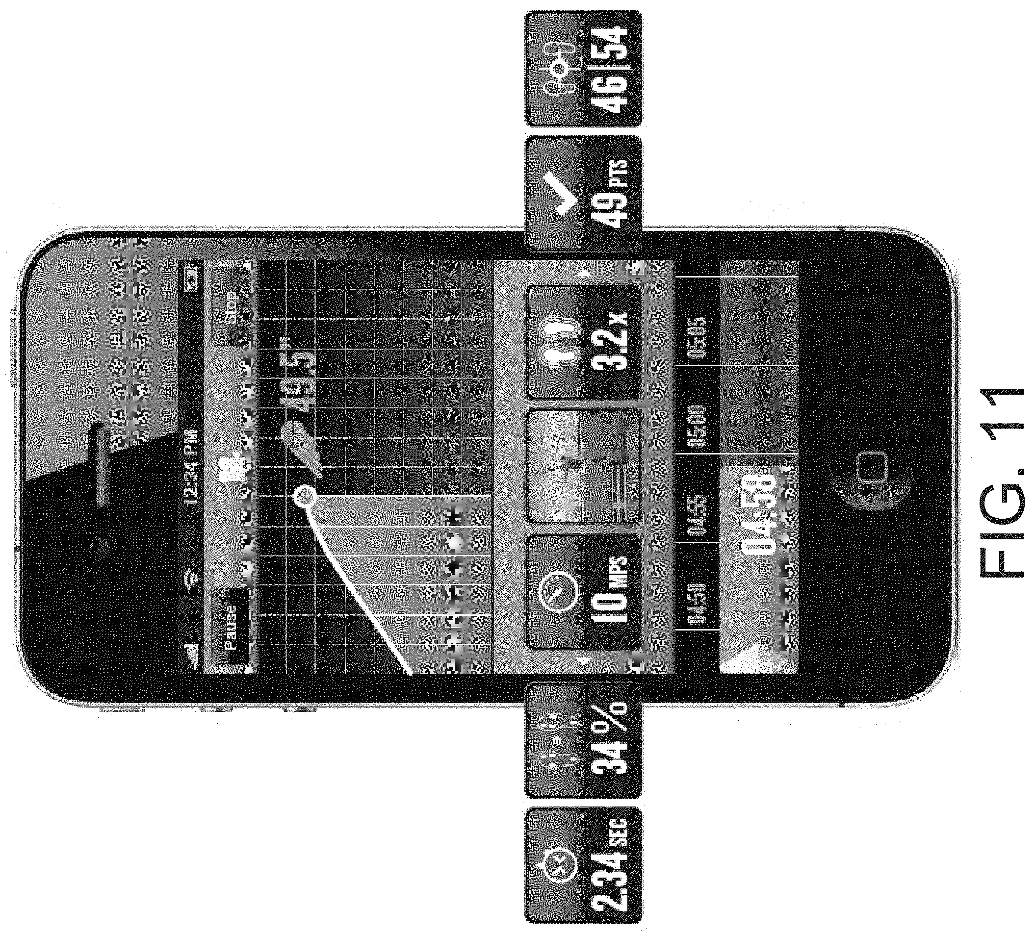
D00014

D00015

D00016

D00017

D00018

D00019

D00020

D00021

D00022

D00023

D00024

D00025

D00026

XML
uspto.report is an independent third-party trademark research tool that is not affiliated, endorsed, or sponsored by the United States Patent and Trademark Office (USPTO) or any other governmental organization. The information provided by uspto.report is based on publicly available data at the time of writing and is intended for informational purposes only.
While we strive to provide accurate and up-to-date information, we do not guarantee the accuracy, completeness, reliability, or suitability of the information displayed on this site. The use of this site is at your own risk. Any reliance you place on such information is therefore strictly at your own risk.
All official trademark data, including owner information, should be verified by visiting the official USPTO website at www.uspto.gov. This site is not intended to replace professional legal advice and should not be used as a substitute for consulting with a legal professional who is knowledgeable about trademark law.