Obstructive sleep apnea treatment devices, systems and methods
Bolea , et al.
U.S. patent number 10,632,306 [Application Number 15/687,271] was granted by the patent office on 2020-04-28 for obstructive sleep apnea treatment devices, systems and methods. This patent grant is currently assigned to LivaNova USA, Inc.. The grantee listed for this patent is LivaNova USA, Inc.. Invention is credited to Robert E. Atkinson, John P. Beck, Stephen L. Bolea, Peter R. Eastwood, Sidney Hauschild, David R. Hillman, Thomas B. Hoegh, Adam K. Hoyhtya, Paula M. Kaplan, Brian D. Kuhnley, Bruce J. Persson, Dale G. Suilmann, Wondimeneh Tesfayesus.


View All Diagrams
| United States Patent | 10,632,306 |
| Bolea , et al. | April 28, 2020 |
Obstructive sleep apnea treatment devices, systems and methods
Abstract
Devices, systems and methods of neurostimulation for treating obstructive sleep apnea.
| Inventors: | Bolea; Stephen L. (Watertown, MN), Hoegh; Thomas B. (Edina, MN), Kuhnley; Brian D. (Maple Grove, MN), Suilmann; Dale G. (Elk River, MN), Persson; Bruce J. (Dresser, WI), Beck; John P. (Prior Lake, MN), Hauschild; Sidney (St. Paul, MN), Kaplan; Paula M. (St. Paul, MN), Hoyhtya; Adam K. (Shoreview, MN), Tesfayesus; Wondimeneh (St. Paul, MN), Atkinson; Robert E. (White Bear Lake, MN), Eastwood; Peter R. (Floreat, AU), Hillman; David R. (Nedlands, AU) | ||||||||||
|---|---|---|---|---|---|---|---|---|---|---|---|
| Applicant: |
|
||||||||||
| Assignee: | LivaNova USA, Inc. (Houston,
TX) |
||||||||||
| Family ID: | 42312203 | ||||||||||
| Appl. No.: | 15/687,271 | ||||||||||
| Filed: | August 25, 2017 |
Prior Publication Data
| Document Identifier | Publication Date | |
|---|---|---|
| US 20180008824 A1 | Jan 11, 2018 | |
Related U.S. Patent Documents
| Application Number | Filing Date | Patent Number | Issue Date | ||
|---|---|---|---|---|---|
| 12650045 | Dec 30, 2009 | 9744354 | |||
| 61204008 | Dec 31, 2008 | ||||
| Current U.S. Class: | 1/1 |
| Current CPC Class: | A61N 1/3601 (20130101); A61N 1/36139 (20130101); A61B 5/4818 (20130101); A61N 1/3611 (20130101); A61B 5/0538 (20130101); A61N 1/0556 (20130101) |
| Current International Class: | A61N 1/36 (20060101); A61N 1/05 (20060101); A61B 5/00 (20060101); A61B 5/053 (20060101) |
References Cited [Referenced By]
U.S. Patent Documents
| 758030 | April 1904 | Carence |
| 1520930 | December 1924 | Calhoun |
| 1701277 | February 1929 | Shindel |
| 1914418 | June 1933 | Goyena |
| 2046664 | July 1936 | Weaver |
| 2151227 | March 1939 | Pawelek |
| 2237954 | April 1941 | Wilsom |
| 2243360 | May 1941 | Slatis et al. |
| 2274886 | March 1942 | Carroll |
| 2526586 | October 1950 | Shuff |
| 2693799 | November 1954 | Herman, Jr. |
| 2777442 | January 1957 | Zelano |
| 2928388 | March 1960 | Jaroslaw |
| 3292703 | December 1966 | Weber |
| 3457917 | July 1969 | Mercurio |
| 3513839 | May 1970 | Vacante |
| 3680555 | August 1972 | Warncke |
| 3722509 | March 1973 | Nebel |
| 3774618 | November 1973 | Avery |
| 3865106 | February 1975 | Palush |
| 3884223 | May 1975 | Keindl |
| 3893463 | July 1975 | Williams |
| 3906936 | September 1975 | Habal |
| 4160252 | July 1979 | Lucas et al. |
| 4160255 | July 1979 | Kobayashi |
| 4178524 | December 1979 | Ritter |
| 4200440 | April 1980 | Renko |
| 4220150 | September 1980 | King |
| 4221217 | September 1980 | Amezcua |
| 4225034 | September 1980 | Sarovich |
| 4239918 | December 1980 | Keeley |
| 4242987 | January 1981 | Viessmann |
| 4267831 | May 1981 | Aguilar |
| 4283867 | August 1981 | Brown |
| 4302951 | December 1981 | Fall et al. |
| 4313442 | February 1982 | Knudson et al. |
| 4346398 | August 1982 | Lai |
| 4374527 | February 1983 | Iversen |
| 4414986 | November 1983 | Dickhudt et al. |
| 4506666 | March 1985 | Durkan |
| 4567892 | February 1986 | Plicchi et al. |
| 4573481 | March 1986 | Bullara |
| 4602624 | July 1986 | Naples et al. |
| 4612934 | September 1986 | Borkan |
| 4777963 | October 1988 | McKenna |
| 4830008 | May 1989 | Meer |
| 4899750 | February 1990 | Ekwall |
| 4915105 | April 1990 | Lee |
| 4919136 | April 1990 | Alt |
| 4934368 | June 1990 | Lynch |
| 4940065 | July 1990 | Tanagho et al. |
| 4960133 | October 1990 | Hewson |
| 4979511 | December 1990 | Terry, Jr. |
| 4996983 | March 1991 | Amrhein |
| 5016808 | May 1991 | Heil et al. |
| 5036862 | August 1991 | Pohndorf |
| 5095905 | March 1992 | Klepinski |
| 5105826 | April 1992 | Smits et al. |
| 5121754 | June 1992 | Mullett |
| 5133354 | July 1992 | Kallok |
| 5146918 | September 1992 | Kallok et al. |
| 5158080 | October 1992 | Kallok |
| 5174287 | December 1992 | Kallok et al. |
| 5178156 | January 1993 | Takishima et al. |
| 5190053 | March 1993 | Meer |
| 5211173 | May 1993 | Kallok et al. |
| 5215082 | June 1993 | Kallok et al. |
| 5277193 | January 1994 | Takishima et al. |
| 5281219 | January 1994 | Kallok |
| 5282468 | February 1994 | Klepinski |
| 5300094 | April 1994 | Kallok et al. |
| 5324321 | June 1994 | Pohndorf et al. |
| 5335657 | August 1994 | Terry, Jr. et al. |
| 5344438 | September 1994 | Testerman et al. |
| 5388578 | February 1995 | Yomtov et al. |
| 5392773 | February 1995 | Bertrand |
| 5417205 | May 1995 | Wang |
| 5425359 | June 1995 | Liou |
| 5458629 | October 1995 | Baudino et al. |
| 5483969 | January 1996 | Testerman et al. |
| 5485836 | January 1996 | Lincoln |
| 5485851 | January 1996 | Erickson |
| 5487756 | January 1996 | Kallesoe et al. |
| 5511543 | April 1996 | Shirley |
| 5522382 | June 1996 | Sullivan et al. |
| 5522862 | June 1996 | Testerman et al. |
| 5531778 | July 1996 | Maschino et al. |
| 5540731 | July 1996 | Testerman |
| 5540732 | July 1996 | Testerman |
| 5540733 | July 1996 | Testerman et al. |
| 5540734 | July 1996 | Zabara |
| 5546938 | August 1996 | McKenzie |
| 5549655 | August 1996 | Erickson |
| 5568808 | October 1996 | Rimkus |
| 5591216 | January 1997 | Testerman et al. |
| 5630411 | May 1997 | Holscher |
| 5682881 | November 1997 | Winthrop et al. |
| 5697105 | December 1997 | White |
| 5697363 | December 1997 | Hart |
| 5730122 | March 1998 | Lurie |
| 5740798 | April 1998 | McKinney |
| 5752511 | May 1998 | Simmons et al. |
| 5787884 | August 1998 | Tovey |
| 5826579 | October 1998 | Remmers et al. |
| 5848589 | December 1998 | Welnetz |
| 5855552 | January 1999 | Houser et al. |
| 5890491 | April 1999 | Rimkus |
| 5895360 | April 1999 | Christopherson et al. |
| 5919220 | July 1999 | Stieglitz et al. |
| 5922014 | July 1999 | Warman et al. |
| 5938596 | August 1999 | Woloszko et al. |
| 5944680 | August 1999 | Christopherson |
| 5947119 | September 1999 | Reznick |
| 6010459 | January 2000 | Silkoff et al. |
| 6015389 | January 2000 | Brown |
| 6021352 | February 2000 | Christopherson et al. |
| 6021354 | February 2000 | Warman et al. |
| 6029667 | February 2000 | Lurie |
| 6041780 | March 2000 | Richard et al. |
| 6051052 | April 2000 | Monereau et al. |
| 6066165 | May 2000 | Racz |
| 6098624 | August 2000 | Utamaru |
| 6109262 | August 2000 | Tovey |
| 6119690 | September 2000 | Pantaleo |
| 6126611 | October 2000 | Bourgeois et al. |
| 6132384 | October 2000 | Christopherson et al. |
| 6198970 | March 2001 | Freed et al. |
| 6201994 | March 2001 | Warman et al. |
| 6205360 | March 2001 | Carter et al. |
| 6217527 | April 2001 | Selmon et al. |
| 6221049 | April 2001 | Selmon et al. |
| 6231546 | May 2001 | Milo et al. |
| 6240316 | May 2001 | Richmond et al. |
| 6244267 | June 2001 | Eifrig |
| 6251126 | June 2001 | Ottenhoff et al. |
| 6269269 | July 2001 | Ottenhoff et al. |
| 6269703 | August 2001 | Bowers |
| 6292703 | September 2001 | Meier et al. |
| 6345202 | February 2002 | Richmond et al. |
| 6366815 | April 2002 | Haugland et al. |
| 6460539 | October 2002 | Japuntich et al. |
| 6484725 | November 2002 | Chi |
| 6511458 | January 2003 | Milo et al. |
| 6514217 | February 2003 | Selmon et al. |
| 6542776 | April 2003 | Gordon et al. |
| 6561188 | May 2003 | Ellis |
| 6587725 | July 2003 | Durand et al. |
| 6600956 | July 2003 | Maschino et al. |
| 6606521 | August 2003 | Paspa et al. |
| 6609031 | August 2003 | Law et al. |
| 6626179 | September 2003 | Pedley |
| 6636767 | October 2003 | Knudson et al. |
| 6641542 | November 2003 | Cho et al. |
| 6647289 | November 2003 | Prutchi |
| 6651652 | November 2003 | Ward |
| 6718982 | April 2004 | Smith et al. |
| 6719725 | April 2004 | Milo et al. |
| 6721603 | April 2004 | Zabara et al. |
| 6772015 | August 2004 | Dahl et al. |
| 6776162 | August 2004 | Wood |
| 6799575 | October 2004 | Carter |
| 6819958 | November 2004 | Weiner et al. |
| 6829503 | December 2004 | Alt |
| 6829508 | December 2004 | Schulman et al. |
| RE38705 | February 2005 | Hill et al. |
| 6876885 | April 2005 | Swoyer et al. |
| 6881192 | April 2005 | Park |
| 6883518 | April 2005 | Mittelstadt et al. |
| 6890306 | May 2005 | Poezevera |
| 6904320 | July 2005 | Park et al. |
| 6907295 | July 2005 | Gross et al. |
| 6928324 | August 2005 | Park et al. |
| 6978171 | December 2005 | Goetz et al. |
| 6997177 | February 2006 | Wood |
| 7027869 | April 2006 | Danek et al. |
| 7054692 | May 2006 | Whitehurst et al. |
| 7065410 | June 2006 | Bardy et al. |
| 7082331 | July 2006 | Park et al. |
| 7087053 | August 2006 | Vanney |
| 7089932 | August 2006 | Dodds |
| 7094206 | August 2006 | Hoffman |
| 7117036 | October 2006 | Florio |
| 7128717 | October 2006 | Thach et al. |
| 7142919 | November 2006 | Hine et al. |
| 7149573 | December 2006 | Wang |
| 7152604 | December 2006 | Hickle et al. |
| 7155278 | December 2006 | King et al. |
| 7156098 | January 2007 | Dolezal et al. |
| 7160252 | January 2007 | Cho et al. |
| 7160255 | January 2007 | Saadat |
| 7178524 | February 2007 | Noble |
| 7200440 | April 2007 | Kim et al. |
| 7225034 | May 2007 | Ries et al. |
| 7239320 | July 2007 | Hall et al. |
| 7239918 | July 2007 | Strother et al. |
| 7239920 | July 2007 | Thacker et al. |
| 7242987 | July 2007 | Holleman et al. |
| 7263996 | September 2007 | Yung Ho |
| 7277749 | October 2007 | Gordon et al. |
| 7283867 | October 2007 | Strother et al. |
| 7302951 | December 2007 | Mittelstadt et al. |
| 7313442 | December 2007 | Velasco et al. |
| 7343202 | March 2008 | Marva et al. |
| 7346398 | March 2008 | Gross et al. |
| 7366572 | April 2008 | Heruth et al. |
| 7396333 | July 2008 | Stahmann et al. |
| 7438686 | October 2008 | Cho et al. |
| 7453928 | November 2008 | Ten et al. |
| 7463928 | December 2008 | Lee et al. |
| 7473227 | January 2009 | Hsu et al. |
| 7515968 | April 2009 | Metzler et al. |
| 7524292 | April 2009 | Cho et al. |
| 7561922 | July 2009 | Cohen et al. |
| 7591265 | September 2009 | Lee et al. |
| 7596413 | September 2009 | Libbus et al. |
| 7596414 | September 2009 | Whitehurst et al. |
| 7627375 | December 2009 | Bardy et al. |
| 7630771 | December 2009 | Cauller |
| 7634315 | December 2009 | Cholette |
| 7636602 | December 2009 | Baru Fassio et al. |
| 7657311 | February 2010 | Bardy et al. |
| 7660632 | February 2010 | Kirby et al. |
| 7662105 | February 2010 | Hatlestad |
| 7672728 | March 2010 | Libbus et al. |
| 7672729 | March 2010 | Koh et al. |
| 7680537 | March 2010 | Stahmann et al. |
| 7680538 | March 2010 | Durand et al. |
| 7684869 | March 2010 | Bradley et al. |
| 7697968 | April 2010 | Moore |
| 7697984 | April 2010 | Hill et al. |
| 7697990 | April 2010 | Ujhazy et al. |
| 7717848 | May 2010 | Heruth et al. |
| 7720534 | May 2010 | Bardy et al. |
| 7725195 | May 2010 | Lima et al. |
| 7725198 | May 2010 | Cross et al. |
| 7734340 | June 2010 | De Ridder |
| 7734348 | June 2010 | Zhang et al. |
| 7738952 | June 2010 | Yun et al. |
| 7747323 | June 2010 | Libbus et al. |
| 7751880 | July 2010 | Cholette |
| 7751885 | July 2010 | Bardy et al. |
| 7758384 | July 2010 | Alexander et al. |
| 7765000 | July 2010 | Zhang et al. |
| 7769461 | August 2010 | Whitehurst et al. |
| 7783353 | August 2010 | Libbus et al. |
| 7785262 | August 2010 | Melker et al. |
| 7787959 | August 2010 | Morgan |
| 7792590 | September 2010 | Pianca et al. |
| 7797050 | September 2010 | Libbus et al. |
| 7797057 | September 2010 | Harris |
| 7797058 | September 2010 | Mrva et al. |
| 7805195 | September 2010 | Zealear |
| 7809442 | October 2010 | Bolea et al. |
| 7813797 | October 2010 | Bardy et al. |
| 7813802 | October 2010 | Tcheng et al. |
| 7813809 | October 2010 | Strother et al. |
| 7818063 | October 2010 | Wallace et al. |
| 7822486 | October 2010 | Foster et al. |
| 7860570 | December 2010 | Whitehurst et al. |
| 7979128 | July 2011 | Tehrani et al. |
| 8221049 | July 2012 | Westendorf et al. |
| 8249723 | August 2012 | McCreery |
| 8311645 | November 2012 | Bolea et al. |
| 8386046 | February 2013 | Tesfayesus et al. |
| 8428727 | April 2013 | Bolea et al. |
| 8498712 | July 2013 | Bolea et al. |
| 8626304 | January 2014 | Bolea et al. |
| 8639354 | January 2014 | Bolea et al. |
| 8718783 | May 2014 | Bolea et al. |
| 8744584 | June 2014 | Camps et al. |
| 8744589 | June 2014 | Bolea et al. |
| 8855771 | October 2014 | Tesfayesus et al. |
| 2001/0010010 | July 2001 | Richmond et al. |
| 2001/0031929 | October 2001 | O'Toole |
| 2002/0010495 | January 2002 | Freed et al. |
| 2002/0049479 | April 2002 | Pitts |
| 2002/0092527 | July 2002 | Wood |
| 2002/0128700 | September 2002 | Cross, Jr. |
| 2002/0156507 | October 2002 | Lindenthaler |
| 2002/0165462 | November 2002 | Westbrook et al. |
| 2002/0166556 | November 2002 | Jacob |
| 2002/0195108 | December 2002 | Mittelstadt et al. |
| 2002/0195109 | December 2002 | Mittelstadt et al. |
| 2003/0034031 | February 2003 | Lev et al. |
| 2003/0078643 | April 2003 | Schulman et al. |
| 2003/0083696 | May 2003 | Avital |
| 2003/0093128 | May 2003 | Freed et al. |
| 2003/0106555 | June 2003 | Tovey |
| 2003/0106556 | June 2003 | Alperovich et al. |
| 2003/0114895 | June 2003 | Gordon et al. |
| 2003/0114905 | June 2003 | Kuzma |
| 2003/0153953 | August 2003 | Park et al. |
| 2003/0167018 | September 2003 | Wyckoff |
| 2003/0195571 | October 2003 | Burnes et al. |
| 2003/0209145 | November 2003 | Soper |
| 2003/0216789 | November 2003 | Deem et al. |
| 2004/0015204 | January 2004 | Whitehurst et al. |
| 2004/0020489 | February 2004 | Gillespie et al. |
| 2004/0049241 | March 2004 | Campos |
| 2004/0055603 | March 2004 | Bruce |
| 2004/0073272 | April 2004 | Knudson et al. |
| 2004/0089303 | May 2004 | Chien |
| 2004/0111139 | June 2004 | McCreery |
| 2004/0116819 | June 2004 | Alt |
| 2004/0116978 | June 2004 | Bradley |
| 2004/0138581 | July 2004 | Frei et al. |
| 2004/0153127 | August 2004 | Gordon et al. |
| 2004/0162499 | August 2004 | Nagai et al. |
| 2004/0194784 | October 2004 | Bertrand |
| 2004/0215288 | October 2004 | Lee et al. |
| 2004/0215290 | October 2004 | Zealear |
| 2004/0230278 | November 2004 | Dahl et al. |
| 2004/0233058 | November 2004 | Dodds |
| 2004/0260310 | December 2004 | Harris |
| 2004/0261791 | December 2004 | Horian |
| 2005/0004610 | January 2005 | Kim et al. |
| 2005/0004810 | January 2005 | Tanaka |
| 2005/0010265 | January 2005 | Baru Fassio et al. |
| 2005/0038490 | February 2005 | Gross et al. |
| 2005/0039757 | February 2005 | Wood |
| 2005/0043644 | February 2005 | Stahmann et al. |
| 2005/0043772 | February 2005 | Stahmann et al. |
| 2005/0076908 | April 2005 | Lee et al. |
| 2005/0085865 | April 2005 | Tehrani |
| 2005/0085866 | April 2005 | Tehrani |
| 2005/0085868 | April 2005 | Tehrani et al. |
| 2005/0085869 | April 2005 | Tehrani et al. |
| 2005/0085874 | April 2005 | Davis et al. |
| 2005/0098176 | May 2005 | Hoffrichter |
| 2005/0101833 | May 2005 | Hsu et al. |
| 2005/0119711 | June 2005 | Cho et al. |
| 2005/0139216 | June 2005 | Mittelstadt et al. |
| 2005/0165457 | July 2005 | Benser et al. |
| 2005/0209513 | September 2005 | Heruth et al. |
| 2005/0209643 | September 2005 | Heruth et al. |
| 2005/0234523 | October 2005 | Levin et al. |
| 2005/0235992 | October 2005 | Djupesland |
| 2005/0240241 | October 2005 | Yun et al. |
| 2005/0251216 | November 2005 | Hill et al. |
| 2005/0261747 | November 2005 | Schuler et al. |
| 2005/0267380 | December 2005 | Poezevara |
| 2005/0267547 | December 2005 | Knudson et al. |
| 2005/0277844 | December 2005 | Stroether et al. |
| 2005/0277999 | December 2005 | Strother et al. |
| 2005/0278000 | December 2005 | Strother et al. |
| 2006/0004429 | January 2006 | Mrva et al. |
| 2006/0005842 | January 2006 | Rashad et al. |
| 2006/0025828 | February 2006 | Armstrong et al. |
| 2006/0030919 | February 2006 | Mrva et al. |
| 2006/0032497 | February 2006 | Doshi |
| 2006/0041295 | February 2006 | Osypka |
| 2006/0052836 | March 2006 | Kim et al. |
| 2006/0058588 | March 2006 | Zdeblick |
| 2006/0058852 | March 2006 | Koh et al. |
| 2006/0064029 | March 2006 | Arad (Abboud) |
| 2006/0064138 | March 2006 | Velasco et al. |
| 2006/0079802 | April 2006 | Jensen et al. |
| 2006/0095088 | May 2006 | De Ridder |
| 2006/0111755 | May 2006 | Stone et al. |
| 2006/0116739 | June 2006 | Betser et al. |
| 2006/0129189 | June 2006 | George et al. |
| 2006/0135886 | June 2006 | Lippert et al. |
| 2006/0136024 | June 2006 | Cohen et al. |
| 2006/0142815 | June 2006 | Tehrani et al. |
| 2006/0144398 | July 2006 | Doshi et al. |
| 2006/0149334 | July 2006 | Tehrani et al. |
| 2006/0149345 | July 2006 | Boggs et al. |
| 2006/0150978 | July 2006 | Doshi et al. |
| 2006/0150979 | July 2006 | Doshi et al. |
| 2006/0150980 | July 2006 | Kim |
| 2006/0167497 | July 2006 | Armstrong et al. |
| 2006/0184204 | August 2006 | He |
| 2006/0195170 | August 2006 | Cohen et al. |
| 2006/0211951 | September 2006 | Milijasevic et al. |
| 2006/0224209 | October 2006 | Meyer |
| 2006/0224211 | October 2006 | Durand et al. |
| 2006/0241506 | October 2006 | Melker et al. |
| 2006/0241708 | October 2006 | Boute |
| 2006/0247729 | November 2006 | Tehrani et al. |
| 2006/0259079 | November 2006 | King |
| 2006/0264777 | November 2006 | Drew |
| 2006/0266369 | November 2006 | Atkinson et al. |
| 2006/0271118 | November 2006 | Libbus et al. |
| 2006/0271137 | November 2006 | Stanton-Hicks |
| 2006/0282127 | December 2006 | Zealear |
| 2006/0293720 | December 2006 | DiLorenzo |
| 2006/0293723 | December 2006 | Whitehurst et al. |
| 2007/0021785 | January 2007 | Inman et al. |
| 2007/0027482 | February 2007 | Parnis et al. |
| 2007/0038265 | February 2007 | Tcheng et al. |
| 2007/0043411 | February 2007 | Foster et al. |
| 2007/0095347 | May 2007 | Lampotang et al. |
| 2007/0150006 | June 2007 | Libbus et al. |
| 2007/0125379 | July 2007 | Pierro et al. |
| 2007/0175478 | August 2007 | Brunst |
| 2007/0227542 | October 2007 | Kashmakov et al. |
| 2007/0239243 | October 2007 | Moffitt et al. |
| 2007/0277832 | December 2007 | Doshi et al. |
| 2007/0282410 | December 2007 | Cross et al. |
| 2007/0283692 | December 2007 | Tetsuka et al. |
| 2007/0283962 | December 2007 | Doshi et al. |
| 2007/0295338 | December 2007 | Loomas et al. |
| 2008/0023007 | January 2008 | Dolezal et al. |
| 2008/0027480 | January 2008 | Van Der Burg et al. |
| 2008/0027502 | January 2008 | Ransom |
| 2008/0041373 | February 2008 | Doshi et al. |
| 2008/0099029 | May 2008 | Lamberg |
| 2008/0103407 | May 2008 | Bolea et al. |
| 2008/0103545 | May 2008 | Bolea et al. |
| 2008/0147142 | June 2008 | Testerman et al. |
| 2008/0163875 | July 2008 | Aarestad et al. |
| 2008/0183254 | July 2008 | Bly et al. |
| 2008/0188947 | August 2008 | Sanders |
| 2009/0044814 | February 2009 | Iancea et al. |
| 2009/0270707 | October 2009 | Alfoqaha et al. |
| 2009/0276024 | November 2009 | Bonde et al. |
| 2009/0308395 | December 2009 | Lee et al. |
| 2009/0318986 | December 2009 | Alo et al. |
| 2009/0326408 | December 2009 | Moon |
| 2010/0016749 | January 2010 | Atsma et al. |
| 2010/0036285 | February 2010 | Govari et al. |
| 2010/0047376 | February 2010 | Imbeau et al. |
| 2010/0076536 | March 2010 | Merz et al. |
| 2010/0094379 | April 2010 | Meadows et al. |
| 2010/0100150 | April 2010 | Kirby et al. |
| 2010/0125310 | May 2010 | Wilson et al. |
| 2010/0131029 | May 2010 | Durand et al. |
| 2010/0137931 | June 2010 | Hopper et al. |
| 2010/0137949 | June 2010 | Mazgalev et al. |
| 2010/0137956 | June 2010 | Osypka |
| 2010/0152553 | June 2010 | Ujhazy et al. |
| 2010/0174341 | July 2010 | Bolea et al. |
| 2010/0228133 | September 2010 | Averina et al. |
| 2010/0228317 | September 2010 | Libbus et al. |
| 2010/0241207 | September 2010 | Bluger |
| 2010/0257729 | October 2010 | Alexander et al. |
| 2010/0262209 | October 2010 | King et al. |
| 2011/0071591 | March 2011 | Bolea et al. |
| 2011/0093032 | April 2011 | Boggs et al. |
| 2012/0017920 | January 2012 | Sanders |
| 2012/0022389 | January 2012 | Sanders |
| 2012/0192874 | August 2012 | Bolea et al. |
| 2013/0085546 | April 2013 | Bolea et al. |
| 0 900 102 | Jul 2004 | EP | |||
| 0 892 926 | Jun 2006 | EP | |||
| 1 404 221 | Feb 2007 | EP | |||
| 1 854 494 | Nov 2007 | EP | |||
| 1 322 384 | Dec 2007 | EP | |||
| 53-118893 | Oct 1978 | JP | |||
| 09-294819 | Nov 1997 | JP | |||
| 2000-508601 | May 2000 | JP | |||
| 2000-508562 | Jul 2000 | JP | |||
| 2003-305135 | Oct 2003 | JP | |||
| 2004-508908 | Mar 2004 | JP | |||
| 2004-532707 | Oct 2004 | JP | |||
| 3688301 | Jun 2005 | JP | |||
| 2005-521485 | Jul 2005 | JP | |||
| 2007-021156 | Feb 2007 | JP | |||
| 2007-021158 | Aug 2007 | JP | |||
| WO-98/20938 | May 1998 | WO | |||
| WO-02/24279 | Mar 2002 | WO | |||
| WO-03/000133 | Jan 2003 | WO | |||
| WO-03/000347 | Jan 2003 | WO | |||
| WO-03/082393 | Oct 2003 | WO | |||
| WO-2005/004993 | Jan 2005 | WO | |||
| WO-2006/045251 | May 2006 | WO | |||
| WO-2006/063339 | Jun 2006 | WO | |||
| WO-2007/134458 | Nov 2007 | WO | |||
| WO-2008/046190 | Apr 2008 | WO | |||
Other References
|
Aziz, L. and Ejnell, H. "Obstructive Sleep Apnea Caused by Bilateral Vocal Fold Paralysis." Ear Nose Throat J. Apr. 2003; 82(4): 326-7. Abstract. cited by applicant . Campbell et al., "Nasal Continuous positive airway pressure from high flow cannula versus Infant Flow for preterm infants," Journal of Perinatology, Jul. 2006, pp. 546-549, vol. 26 (9), Nature Publishing Group. cited by applicant . De Almeida et al., "Nasal pressure recordings to detect obstructive sleep apnea," Sleep and Breathing, Feb. 25, 2006, pp. 62-69, vol. 10 (2), Springer Heidelberg. cited by applicant . Eastwood et al., "Treating Obstructive Sleep Apnea with Hypoglossal Nerve Stimulation," Sleep, 2011, pp. 1479-1486B, vol. 34, No. 11. cited by applicant . Ferguson et al., "Effect of Mandibular and Tongue Protrusion on Upper Airway Size During Wakefulness," American Journal of Respiratory and Critical Care Medicine, 1997, pp. 1748-1754, vol. 1553. cited by applicant . Goding JR et al., "Relief of Upper Airway Obstruction With Hypoglossal Nerve Stimulation in the Canine", The Laryngoscope, Feb. 1998, pp. 162-169, vol. 108, Lippincott-Raven Publishers, U.S.A. cited by applicant . Huang et al. "Dilation of the oropharynx via selective stimulation of the hypoglossal nerve." J. Neural Eng. 2005; 2:73-80. cited by applicant . Isono et al., "Interaction of cross-sectional area, driving pressure, and airflow of passive velopharynx," American Physiological Society, 1997, pp. 851-859, vol. 83. cited by applicant . Kirkness et al., "Nasal airflow dynamics: mechanisms and responses associated with an external nasal dilator strip," University of Western Sydney, T.C. Amis School of Science, Department of Respiratory Medicine, Westmead Hospital and University of Sydney, Westmead, Australia, 2000. cited by applicant . Mahadevia et al., "Effects of expiratory positive airway pressure on sleep-induced respiratory abnormalities in patients with hypersomnia-sleep apnea syndrome," Am. Rev. Respir. Cis., Feb. 1983, vol. 128, pp. 708-711. cited by applicant . Mann EA, et al., "The Effect of Neuromuscular Stimulation of the Genioglossus on the Hypopharyngeal Airway." Laryngoscope 112: 351-356, 2002. cited by applicant . Noseda et al., "Compliance with nasal continuous positive airway pressure assessed with a pressure monitor: pattern of use and influence of sleep habits," Chest Clinics and Sleep Laboratories, Hopitaux Erasme et Brugmann, Universite Libre de Bruxelles, Brussels, Belgium, 2000, vol. 94, pp. 76-81. cited by applicant . Oliven et al., "Effect of genioglossus contraction on pharyngeal lumen and airflow in sleep apnoea patients," European Respiratory Journal, 2007, pp. 748-758, vol. 30, No. 4. cited by applicant . Paquereau et al., "Positive pressure titration in the treatment of obstructive sleep apnea syndrome using continuous airway positive pressure," Revue Des Maladies Respiratoires, Apr. 2000, pp. 459-465, vol. 17 (2), Masson Editeur. cited by applicant . Sahin et al., "Chronic recordings of hypoglossal nerve activity in a dog model of upper airway obstruction," Journal of Applied Physiology 87(6), 1999, The American Physiological Society, pp. 2197-2206. cited by applicant . Saslow et al., "Work of breathing using high-flow nasal cannula in preterm infants," Journal of Perinatology, May 11, 2006, pp. 476-480, vol. 26 (8), Nature Publishing Group. cited by applicant . Schwartz et al. "Therapeutic Electrical Stimulation of the Hypoglossal Nerve in Obstructive Sleep Apnea." Arch Otolaryngol Head Neck Surg/vol. 127, Oct. 2001 (8 pages). cited by applicant . Spence et al., "High-flow nasal cannula as a device to provide continuous positive airway pressure in infants," Journal of Perinatolgy, Dec. 2007, pp. 772-775, vol. 27 (12), Nature Publishing Group. cited by applicant . Stern et al. "Obstructive sleep apnea following treatment of head and neck cancer", Ear, Nose, and Throat Journal, Feb. 2007, vol. 86, No. 2, pp. 101-103. cited by applicant . Strollo et al., "Upper-Airway Stimulation for Obstructive Sleep Apnea," New England Journal of Medicine, 2014, pp. 139-149, N Engl J. Med 270;2. cited by applicant . Tiran et al., "An Improved Device for Posterior Rhinomanometry to Measure Nasal Resistance," Journal of Biomechnical Engineering, Nov. 2005, vol. 127, pp. 994-997. cited by applicant . Trevisanuto et al., "A new device for administration of continuous positive airway pressure in preterm infants: comparison with a standard nasal CPAP continuous positive airway pressure system," Intensive Care Medicine, Apr. 2005, pp. 859-864, vol. 31 (6), Springer-Verlag. cited by applicant . Verse et al., "New developments in the therapy of obstructive sleep apnea," European Archives of Oto-Rhino-Larvngologv, Jan. 2001, pp. 31-37, vol. 258 (1), Springer-Verlag. cited by applicant . Wells, Jonathan, et al., Biophysical Mechanisms of Transient Optical Stimulation of Peripheral Nerve, Biophysical Journal, Oct. 2007, pp. 2567-2580, vol. 93. cited by applicant . European Search Report issued in corresponding European Application No. 12163791 dated Jun. 25, 2012, (3 pages). cited by applicant . Partial European Search Report dated Aug. 19, 2009 issued in European Patent Application No. 09161958.5 (4 pages). cited by applicant . Response to the Notice of Opposition for Opposition against patent EP 2116274 dated Dec. 2, 2013 (30 pages). cited by applicant . Statement of Grounds filed in Opposition of EP Patent No. 2116274 dated Jul. 25, 2012 (32 pages). cited by applicant. |
Primary Examiner: D Abreu; Michael J
Attorney, Agent or Firm: Foley & Lardner LLP
Parent Case Text
CROSS-REFERENCE TO RELATED APPLICATIONS
This application is a continuation of U.S. patent application Ser. No. 12/650,045, filed Dec. 30, 2009, which claims the benefits of priority under 35 U.S.C. .sctn..sctn. 119 and 120 to U.S. Provisional Patent Application No. 61/204,008, filed Dec. 31, 2008. This application is also related to U.S. Pat. Nos. 7,809,442 and 8,417,343, both filed on Oct. 12, 2007. The entire contents of each of these applications is incorporated herein by reference.
Claims
What is claimed is:
1. An implantable neurostimulation system for delivering a respiratory therapy to a subject, comprising: a neurostimulator adapted to deliver a neurostimulation signal to the subject, the neurostimulator comprising a microprocessor programmed to: titrate a stimulation setting of the neurostimulator while the subject is awake by delivering a first set of stimulation pulses at a plurality of first stimulation setting values between a lower limit defined by a capture threshold corresponding to a beneficial effect of the respiratory therapy and a first upper limit defined by a comfort threshold corresponding to a negative sensation experienced by the subject; and subsequently, when the subject is asleep, repeat the step of titrating the stimulation setting of the neurostimulator by delivering a second set of stimulation pulses at a plurality of second stimulation setting values, wherein one or more of the plurality of second stimulation setting values is different than one or more of the plurality of first stimulation setting values and the plurality of second stimulation setting values are between the lower limit defined by the capture threshold and a second upper limit defined by a threshold at which the patient is expected to at least partially arouse from sleep.
2. The neurostimulation system of claim 1, wherein the awake titration includes determining a stimulation level that causes the subject discomfort.
3. The neurostimulation system of claim 2, wherein the microprocessor is further programmed to, as part of the asleep titration, compare the subject's responses to the second and third sets of stimulation pulses.
4. The neurostimulation system of claim 2, wherein the third set of stimulation pulses has a different amplitude than the second set of stimulation pulses.
5. The neurostimulation system of claim 2, wherein the second and third sets of stimulation pulses are delivered in a sequence to define a stimulation pattern.
6. The neurostimulation system of claim 2, wherein the awake titration includes determining a stimulation level operating window.
7. The neurostimulation system of claim 1, wherein the microprocessor is programmed to perform at least one of the awake titration or the asleep titration in response to an input from a user.
8. The neurostimulation system of claim 7, wherein the input defines at least one of the lower limit, the first upper limit, or the second upper limit.
9. The neurostimulation system of claim 1, wherein the awake titration includes determining a stimulation level operating window.
10. The neurostimulation system of claim 1, wherein the awake titration includes determining a stimulation level that causes muscle contraction.
11. The neurostimulation system of claim 1, wherein the microprocessor is further programmed to, as part of the asleep titration, subsequently deliver a third set of stimulation pulses at a plurality of third stimulation setting values, wherein one or more of the plurality of third stimulation setting values is different than one or more of the plurality of second stimulation setting values.
12. The neurostimulation system of claim 1, wherein the awake titration defines a stimulation level operating window having a capture stimulation level and a maximum comfort stimulation level inclusively between which the first set of stimulation pulses is delivered, the capture stimulation level corresponding to respiratory muscle movement, the maximum comfort stimulation level being greater than the capture stimulation level.
13. The neurostimulation system of claim 1, wherein the second set of stimulation pulses are delivered at a magnitude that is greater than the maximum comfort stimulation level.
Description
FIELD OF THE INVENTION
The inventions described herein relate to devices, systems and associated methods for treating sleep disordered breathing. More particularly, the inventions described herein relate to devices, systems and methods for treating obstructive sleep apnea.
BACKGROUND OF THE INVENTION
Obstructive sleep apnea (OSA) is highly prevalent, affecting one in five adults in the United States. One in fifteen adults has moderate to severe OSA requiring treatment. Untreated OSA results in reduced quality of life measures and increased risk of disease including hypertension, stroke, heart disease, etc.
Continuous positive airway pressure (CPAP) is a standard treatment for OSA. While CPAP is non-invasive and highly effective, it is not well tolerated by patients. Patient compliance for CPAP is often reported to be between 40% and 60%.
Surgical treatment options for OSA are available too. However, they tend to be highly invasive (result in structural changes), irreversible, and have poor and/or inconsistent efficacy. Even the more effective surgical procedures are undesirable because they usually require multiple invasive and irreversible operations, they may alter a patient's appearance (e.g., maxillo-mandibular advancement), and/or they may be socially stigmatic (e.g., tracheostomy).
U.S. Pat. No. 4,830,008 to Meer proposes hypoglossal nerve stimulation as an alternative treatment for OSA. An example of an implanted hypoglossal nerve stimulator for OSA treatment is the Inspire.TM. technology developed by Medtronic, Inc. (Fridely, Minn.). The Inspire device is not FDA approved and is not for commercial sale. The Inspire device includes an implanted neurostimulator, an implanted nerve cuff electrode connected to the neurostimulator by a lead, and an implanted intra-thoracic pressure sensor for respiratory feedback and stimulus trigger. The Inspire device was shown to be efficacious (approximately 75% response rate as defined by a 50% or more reduction in RDI and a post RDI of .ltoreq.20) in an eight patient human clinical study, the results of which were published by Schwartz et al. and Eisele et al. However, both authors reported that only three of eight patients remained free from device malfunction, thus demonstrating the need for improvements.
SUMMARY OF THE INVENTION
To address this and other unmet needs, the present invention provides, in exemplary non-limiting embodiments, devices, systems and methods for nerve stimulation for OSA therapy as described in the following detailed description.
BRIEF DESCRIPTION OF THE DRAWINGS
It is to be understood that both the foregoing summary and the following detailed description are exemplary. Together with the following detailed description, the drawings illustrate exemplary embodiments and serve to explain certain principles. In the drawings:
FIG. 1 is a schematic illustration of a system according to an embodiment of the present invention, including internal (chronically implanted) and external components;
FIG. 2 is a perspective view of a stimulation lead for use in the system shown in FIG. 1, including a detailed view of the distal end of the stimulation lead;
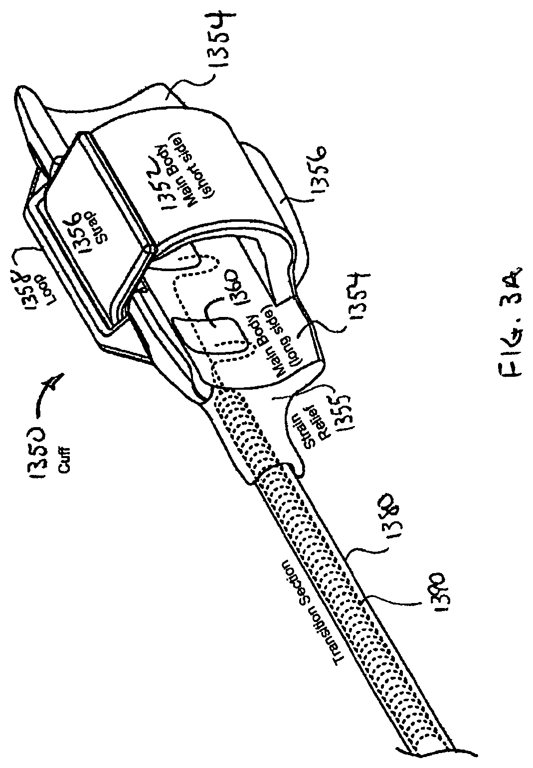
FIG. 3A is a detailed perspective view of the cuff of the stimulation lead shown in FIG. 2;
FIG. 3B is a lateral cross-sectional view of the cuff shown in FIGS. 2 and 3A;
FIG. 4A is a perspective view of a respiration sensing lead for use in the system shown in FIG. 1;
FIG. 4B is a detailed perspective view of the proximal electrode pair of the respiration sensing lead shown in FIG. 4A;
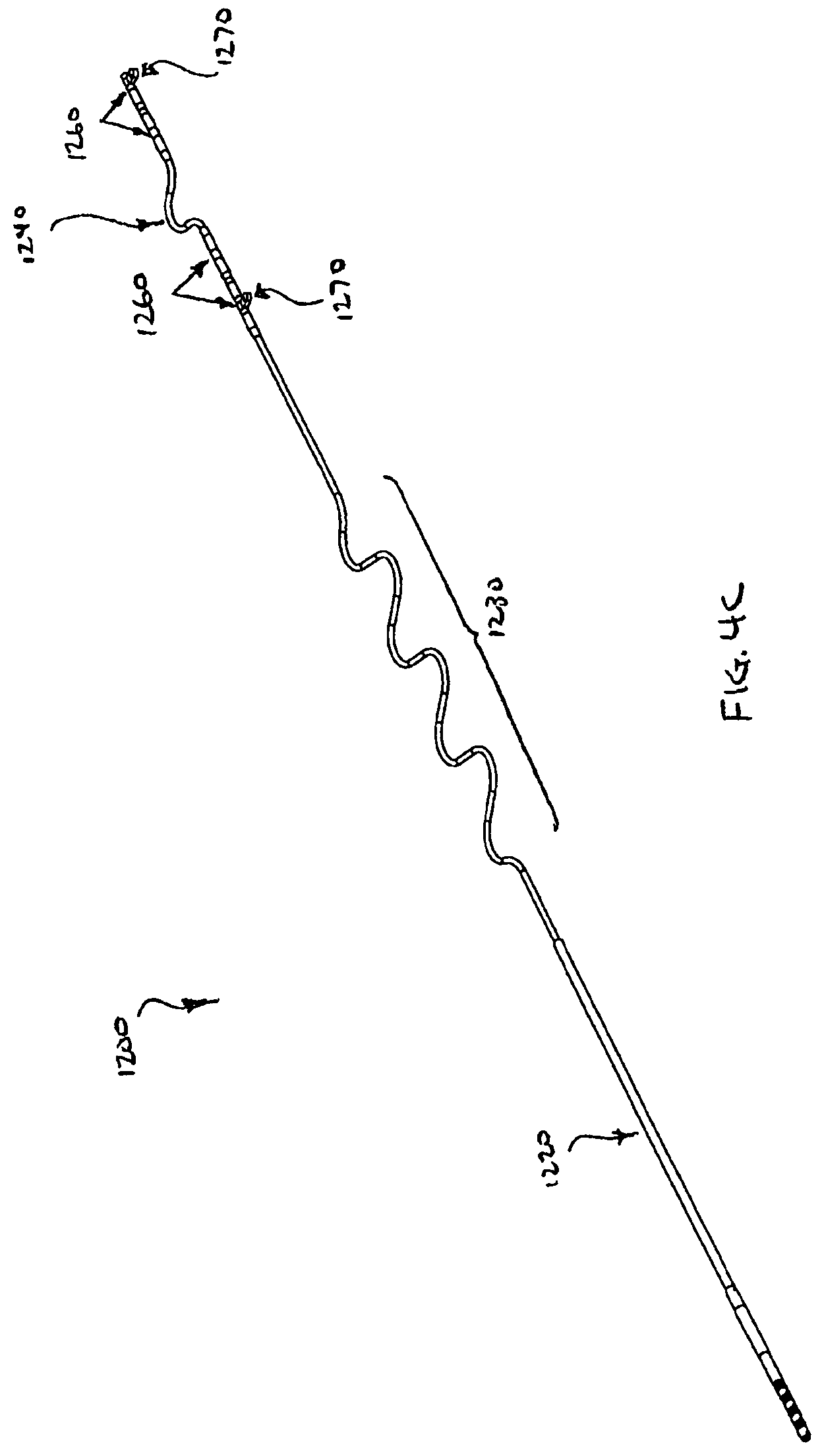
FIG. 4C is a perspective view of an alternative respiration sensing lead for use in the system shown in FIG. 1;
FIG. 5A shows front, side and top views of an implantable neurostimulator for use in the system shown in FIG. 1;
FIG. 5B is a schematic block diagram of electronic circuitry for use in the implantable neurostimulator shown in FIG. 5A;
FIGS. 6A, 6B, 6C and 6D illustrate a bio-impedance signal, the corresponding physiological events, and trigger algorithms for use in the system shown in FIG. 1;
FIG. 7A is a schematic illustration of the programmer system for use in the system shown in FIG. 1;
FIGS. 7B and 7C are schematic block diagrams of electronic circuitry for use in the programmer system for shown in FIG. 7A;
FIG. 8A is a schematic illustration of the therapy controller for use in the system shown in FIG. 1;
FIG. 8B is a schematic block diagram of electronic circuitry for use in the therapy controller shown in FIG. 8A;
FIG. 9 is a top view of a magnet for use in the system shown in FIG. 1;
FIG. 10A is a schematic illustration of an interface of the system shown in FIG. 1 and polysomnographic equipment as may be used in a sleep study for therapy titration or therapy assessment, for example;
FIG. 10B is a schematic illustration of an alternative interface of the system shown in FIG. 1;
FIGS. 11A and 11D are anatomical illustrations showing the incision sites and tunneling paths that may be used for implanting the internal components shown in FIG. 1;
FIG. 11B is a perspective view of a disassembled tunneling tool for use in tunneling the leads of the system shown in FIG. 1;
FIG. 11C is a detailed perspective view of the assembled tunneling tool shown in FIG. 11B, but with the cap removed to expose the jaws for grasping the lead carrier disposed on the proximal end of a lead;
FIGS. 11E and 11F illustrate an alternative tunneling tool for use in tunneling the leads of the system shown in FIG. 1;
FIG. 12 is a schematic illustration of an external stimulator system and polysomnographic equipment as may be used for direct muscle stimulation using fine wire electrodes as a therapy efficacy screening method, for example;
FIG. 13 is a schematic illustration of a bio-impedance monitoring system using surface electrodes and polysomnographic equipment as may be used as a respiratory sensing screening method, for example;
FIGS. 14A and 14B are charts showing various stimulation output modes of the implantable neurostimulator shown in FIG. 1 as may be used for therapy titration, for example; and
FIGS. 15A, 15B, 15C, 16A, 16B, 17, 18A and 18B are charts illustrating various therapy titration methodologies.
DETAILED DESCRIPTION OF EXEMPLARY EMBODIMENTS
The following detailed description should be read with reference to the drawings in which similar elements in different drawings are numbered the same. The drawings, which are not necessarily to scale, depict illustrative embodiments and are not intended to limit the scope of the invention.
Overall System
FIG. 1 schematically illustrates a hypoglossal nerve stimulation (HGNS) system 100 comprising internal components 1000 and external components 2000. The HGNS system 100 treats obstructive sleep apnea (OSA) by restoring neuromuscular activity to the genioglossus muscle via stimulation of the hypoglossal nerve (HGN) synchronous with inspiration to mitigate upper airway collapse during sleep. Stimulation is generated by an implantable neurostimulator (INS) 1100, synchronized with inspiration as measured by respiration sensing leads (RSLs) 1200 using bio-impedance, and delivered to the hypoglossal nerve by a stimulation lead (STL) 1300. A programmer system 2100 and a therapy controller 2500 are wirelessly linked to the INS 1100. The programmer system 2100 includes a computer 2300, a programmer interface 2400, and a programmer head 2200. The programmer system 2100 is used by the physician to control and program the INS 1100 during surgery and therapy titration, and the therapy controller 2500 is used by the patient to control limited aspects of therapy delivery.
The implanted components 1000 of the HGNS system 100 include the INS 1100, STL 1300, and RSLs 1200. The INS is designed to accommodate one or two STLs 1300 and one or two RSLs 1200. One STL 1300 may be used for unilateral implantation and unilateral hypoglossal nerve stimulation. Two STLs 1300 may be used for bilateral implantation on both the right and left hypoglossal nerves to enhance the effects of stimulation. Alternatively, a second STL 1300 may be used as a back-up in the event of re-operation necessitated by failure or suboptimal placement of the first STL 1300. Similarly, one RSL 1200 may be used for respiration detection, but two RSLs 1200 may be used for enhanced sensing capability or redundancy. Alternatively, a second RSL 1200 may be used as a back-up in the event of re-operation necessitated by failure or suboptimal placement of the first RSL 1200. Port plugs (not shown) may be used to seal the unused ports in the header of the INS 1100. If only one STL 1300 and one RSL 1200 are to be used, the INS 1100 may be simplified to accommodate one of each lead, thus reducing the size and complexity of the INS 1100, as well as increasing battery longevity. For purposes of illustration, not limitation, the INS 1100 is shown with two RSLs 1200 and one STL 1300.
The implanted components 1000 may be surgically implanted with the patient under general anesthesia. The INS 1100 may be implanted in a subcutaneous pocket inferior to the clavicle over the pectoralis fascia. The distal end of the STL 1300 (cuff 1350) may be implanted on the hypoglossal nerve or a branch of the hypoglossal nerve in the submandibular region, and the proximal end of the STL 1300 may be tunneled under the skin to the INS 1100. The RSL 1300 may be tunneled under the skin from the INS 1100 to the rib cage. The INS 1100 detects respiration via the RSLs 1200 using bio-impedance.
Stimulation Lead (STL)
FIG. 2 schematically illustrates the STL 1300 in more detail. The STL 1300 is designed to deliver the stimulation signal from the INS 1100 to the hypoglossal nerve and includes a proximal connector assembly 1310, a main tubular body 1330, and a distal cuff 1350. The main tubular body of the STL includes a sigmoid shaped section 1370 and a distal flexible transition section 1380 proximal of the cuff. The STL may have a nominal outside diameter of 0.062 inches to have minimal cosmetic impact, and an overall length of 17.7 inches (45 cm) (including cuff) to extend from the infraclavicular region (INS) to the submandibular region (hypoglossal nerve) and to accommodate anatomical variation.
The main tubular body 1330 of the STL 1300 is designed to withstand gross neck movement as well as mandibular movement and hypoglossal nerve movement caused by talking, chewing, swallowing, etc. To survive in this high fatigue environment, the main tubular body 1330 incorporates a highly compliant silicone jacket in the form of a sigmoid, and two conductors 1390 (one for cathode electrodes, one for anode electrodes) each comprising ETFE insulated MP35N multifilament cable disposed inside the jacket in the form of a bi-filar coil (not visible). This design provides high fatigue resistance and three-dimensional flexibility (bending and elongation).
The proximal connector assembly 1310 is designed to provide a reliable mechanical and electrical connection of the STL 1300 to the INS 1100. It has a number of strain relief elements that enable it to withstand handling during insertion and removal from the INS 1100, as well as adverse conditions encountered when implanted. The connector assembly 1310 includes two in-line stainless steel ring contacts (one for each conductor 1390) and two silicone ring seals. Set screws in the header of the INS 1100 bear down on the contacts, and together with the ring seals, provide a sealed mechanical and electrical connection to the INS 1100. More detailed views of the cuff 1350 are shown in FIGS. 3A and 3B, wherein FIG. 3A schematically illustrates the cuff 1350 in isometric view, and FIG. 3B schematically illustrates the cuff 1350 in cross-sectional view. The cuff 1350 has a hinged oval-shaped silicone body (collectively 1352 and 1354) to define an oval lumen 1355 that provides secure and gentle retention around the hypoglossal nerve. The cuff 1350 may be designed to fit the nerve very closely to minimize tissue growth between the electrode and nerve. Thus, the cuff may be available in two sizes to accommodate nerves of different diameter: a small size to accommodate nerves having a diameter of up to about 2.5-3.0 mm, and a large size to accommodate nerves having a diameter of up to 3.2-4.0 mm. At 3.0 mm nerve diameter, either size cuff will fit the nerve with minimal open space for tissue in-growth. Using a large cuff on a 2.5 mm nerve allows clearance between the nerve and electrode which promotes capsule formation. This may cause an increase in capture threshold but will not affect safety. Conversely, a small cuff placed on a large nerve minimizes electrode coverage around the nerve and may fall off with swelling. The short side 1352 (e.g., 4.0 mm long) of the cuff body fits between nerve branches and connective tissue on the deep side of the nerve, thereby minimization nerve dissection. The long side 1354 (e.g., 10.0 mm long) of the cuff body rests on the superficial side of the nerve (where few braches exist) and is connected to the transition section 1380 of the main lead body 1330.
A silicone strap 1356 is connected to and extends from the short side 1352 of the cuff body. A silicone top plate comprising an integral base portion 1359 and loop 1358 is attached to and covers the exterior surface of the long side 1354 of the cuff body. The strap 1356 freely slides through the loop 1358, and wraps around the long side 1354 of the cuff body. The strap 1356 is removed from the loop 1358 for placement of the cuff 1350 around the nerve and reinserted into the loop 1358 to hold the cuff 1350 on the nerve. A mark may be disposed on the strap 1356 of the small size cuff to indicate that the cuff is too small and that a larger size cuff should be used if the mark does not pass through the loop 1358. The cuff body readily expands along a hinge line 1353 (defined at the junction of the short side 1352 to the long side 1354) as well as other portions of the cuff 1350 structure. Expansion of the cuff body accommodates nerves of different diameters and nerve swelling after implantation, while the strap 1356 remains in the loop 1358 to retain the cuff 1350 on the nerve. In the event of excess nerve swelling (e.g., >50% increase in nerve diameter) or traction from the lead 1300 (e.g., as may accidentally occur during implantation), the strap 1356 pulls out of the loop 1358 and releases the cuff 1350 from the nerve to minimize the potential for nerve damage.
The cuff body carries four platinum-iridium electrodes 1360 (e.g., 2.0 mm.sup.2 exposed area each for small cuff, 3.0 mm.sup.2 exposed area each for large cuff), with one cathode electrode 1360 on the short side 1352, another cathode electrode 1360 (not visible) diametrically opposed on the long side 1354, and two anode electrodes 1360 guarding the cathode electrode 1360 on the long side 1354. This guarded dual cathode arrangement provides a more uniform electrical field throughout the cross-section of the nerve while minimizing electrical field outside of the cuff. One conductor 1390 may be connected to the cathode electrode 1360 on the long side, to which the other cathode electrode 1360 on the short side is connected by a jumper wire. Similarly, the other conductor 1390 may be connected to the distal anode electrode 1360, to which the proximal anode electrode 1360 is connected by jumper wire. With this arrangement, the cathode electrodes are commonly connected to one conductor 1390 and the anode electrodes are commonly connected to the other conductor 1390.
With the exception of the metal electrode contacts in the cuff, all external surfaces of the STL 1300 exposed to the body when implanted may comprise implantable grade polymers selected from the following: silicone, and fully cured silicone adhesive. The metal electrode contacts in the cuff may comprise implantable grade platinum-iridium and are secured to the silicone cuff body with silicone adhesive, for example.
Respiration Sensing Lead (RSL)
FIGS. 4A and 4B schematically illustrate the respiration sensing lead 1200 in more detail. The respiration sensing lead 1200 is designed to measure bio-impedance and includes a proximal connector assembly 1210, a main tubular body 1220, and two distal ring electrode pairs 1260. The main tubular body 1220 of the RSL 1200 includes a proximal sigmoid section 1230 and a distal sigmoid section 1240 between the electrode pairs 1260. The RSL 1200 may have a nominal outside diameter of 0.072 inches to have minimal cosmetic impact, and an overall length of 24.3 inches (61.6 cm) unstretched, 32.0 inches (81.3 cm) stretched to extend from the infraclavicular region (where the INS 1100 is implanted) to the right or left rib cage (where the RSLs 1200 may be implanted) and to accommodate anatomical variation.
The main tubular lead body 1220 of the RSL 1200 is designed to withstand thoracic movement due to flexion, extension, rotation and breathing. To withstand this environment, the main tubular body 1220 may include a flexible silicone jacket formed into two sigmoid sections 1230, 1240 and four conductors comprising small diameter ETFE insulated MP35NLT wires (not visible) disposed inside the jacket in the form of a quad-filar coil. The proximal sigmoid section 1230 isolates movement of the INS 1100 from the electrode pairs 1260 and accommodates anatomic variations in thoracic length. The distal sigmoid section 1240 allows adjustment in the distance between electrode pairs 1260 and reduces strain applied between the anchor tabs 1270, which may be secured with sutures to the underlying fascia when implanted. The proximal sigmoid 1230 section may have 31/2 wavelengths with a peak-to-peak dimension of approximately 0.94 inches (2.4 cm) and an overall length of 5.5 inches (14.0 cm). The distal sigmoid 1240 section may have 21/2 wavelengths with a peak-to-peak dimension of approximately 0.94 inches (2.4 cm) and an overall length of 5.5 inches (14.0 cm).
The two distal electrode pairs 1260 may comprise four electrodes total, and each may comprise MP35N rings having an exposed surface area of 28.0 mm.sup.2, for example. As shown in FIG. 4B, tubular strain relief segments 1262 and 1272 may be disposed on the lead body on either side of each electrode 1260. Where the strain relief segments 1262 and 1272 are adjacent each other, a gap may be provided there between as shown in FIG. 4B or the segments may abut each other to avoid a stress concentration point. The anchor tab 1270 may be disposed over an electrode as shown in FIG. 4B leaving the proximal and distal extremities of the electrode exposed.
At any given time, the INS 1100 detects impedance along a vector, with each end of the vector defined by one active pair of electrodes 1260. In each active pair of electrodes 1260, one electrode delivers a small excitation current, and the other electrode monitors the corresponding change in voltage. The INS 1100 may also act as a current emitting and/or voltage sensing electrode. Changes in impedance are calculated by dividing the change in voltage by the excitation current, which correspond to movement of the diaphragm and lung to produce a signal indicative of respiratory activity.
The proximal connector assembly 1210 of the RSL 1200 is designed to provide a reliable mechanical and electrical connection of the RSL 1200 to the INS 1100. It has a number of strain relief elements that enable it to withstand handling during insertion and removal from the INS 1100, as well as adverse conditions encountered when implanted. The connector assembly 1210 may include four in-line stainless steel ring contacts (one for each conductor) and four silicone ring seals. Set screws in the header of the INS 1100 bear down on the contacts, and together with ring seals, provide a sealed mechanical and electrical connection to the INS 1100.
With the exception of the distal electrodes, all external surfaces of the RSL 1200 exposed to the body when implanted may comprise implantable grade polymers selected from the following: silicone, and fully cured silicone adhesive. The distal electrodes may comprise implantable grade MP35N and are sealed to the lead body with silicone adhesive, for example.
FIG. 4C schematically illustrates an alternative embodiment of the respiration sensing lead 1200. In this embodiment, the RSL 1200 may have a nominal outside diameter of 0.072 inches to have minimal cosmetic impact, and an overall length of 23.5 inches (59.7 cm) unstretched, 26.5 inches (67.2 cm) stretched. The proximal sigmoid 1230 section may have 31/2 wavelengths with a peak-to-peak dimension of approximately 0.94 inches (2.4 cm) and an overall length of 5.5 inches (14.0 cm). The distal sigmoid 1240 section may have 1/2 wavelength with an amplitude of approximately 1.7 inches (4.4 cm) and an overall length of about 0.5 inches (1.3 cm).
Implantable Neurostimulator (INS)
FIG. 5A schematically illustrates the INS 1100 in more detail, including a front view, a top view and a side view. The INS 1100 is similar in certain aspects to commercially available implantable pulse generators and implantable neurostimulators, which may be obtained from suitable manufacturers such as CCC Medical Devices (Montevideo, Uruguay). The INS 1100 generally includes a header 1110 for connection of the STL 1300 and RSLs 1200, and a hermetically sealed housing 1120 for containing the associated electronics 1130 and battery 1140 (e.g., WGL 9086).
The electronic circuitry 1130 contained in the INS 1100 enables telemetry communication with the programmer system 2100 and therapy controller 2500, detection of respiration via the RSLs 1200, determination of the trigger point for stimulation, and delivery of a controlled electrical stimulation signal (pulse train) via the STL 1300. The INS 1100 also records therapy data (device settings, respiration data, stimulation delivery data, etc.).
The header 1110 may comprise epoxy that is hermetically sealed to the housing 1120. The housing 1120 may comprise titanium. As mentioned in the context of respiration sensing, the housing 1120 may be used as an electrode for bio-impedance respiration measurement. For example, the housing 1120 may comprise a combination current emitting and voltage sensing electrode for respiration detection.
The header 1110 includes four ports: two RSL ports 1112 (labeled "sense" A and B) for receiving the proximal connectors of up to two RSLs 1200 and two STL ports 1114 (labeled "stim" 1 and 2) for receiving the proximal connectors of up to two STLs 1300. Each port that is configured to receive a STL 1300 includes two set screws (labeled "-" for cathode and "+" for anode) with associated set screw blocks and seals for mechanical and electrical connection to corresponding contacts on the proximal connector 1310 of the STL 1300. Similarly, each port that is configured to receive a RSL 1200 includes four set screws (two labeled "I" for current emitting electrodes and two labeled "V" for voltage sensing electrodes) with associated set screw blocks and seals for mechanical and electrical connection to corresponding contacts on the proximal connector 1210 of the RSL 1200. The header 1110 further includes two suture holes 1116 (only one is visible) for securing the INS 1100 to subcutaneous tissue such as muscle fascia using sutures when implanted in a subcutaneous pocket. As shown, approximate dimensions, component values and component configurations are given by way of example, not limitation.
The INS 1100 generates the stimulation output for delivery to the hypoglossal nerve by way of the STL 1300. For this purpose, the INS 1100 has two bipolar stimulation output channels, one channel corresponding to each STL port 1114, with each channel providing a pulse train of constant current with a frequency range of 20 to 50 Hz, a pulse width range of 30 to 215 .mu.s, an amplitude range of 0.4 to 5.0 mA, and a stimulation duty cycle range of 41%-69%, by way of example, not limitation.
The INS 110 also generates the excitation signal and measures voltage by way of the RSLs 1200 for bio-impedance respiration detection. For this purpose, the INS 1100 also has two respiration sensing channels, one channel corresponding to each RSL port 1112, with each channel providing a small excitation current ("I") and measuring voltage ("V"). The excitation signal may comprise a 10 Hz biphasic constant current pulse, with the positive and negative phases of each biphasic pulse having an amplitude of 300 .mu.A, a duration of 50 .mu.s, and a charge of 15 nC. Changes in impedance ("Z") are calculated by dividing the change in measured voltage ("V") by the excitation current ("I"), which corresponds to movement of the diaphragm, lung, and other structures to produce a signal indicative of respiratory activity.
With reference to FIG. 5B, a block diagram of an example of the INS circuit 1130 is shown schematically. The INS circuit 1130 utilizes a microprocessor to control telemetry communications with the programmer system 2100, operating the sensing circuits to monitor respiration via the RSLs 1200, controlling the delivery of output stimuli via the STLs 1300, monitoring the magnetically sensitive reed switch and the real-time clock. The microprocessor contains built-in support circuits (RAM, Flash Memory, Analog to Digital (A/D) Converter, Timers, Serial Ports and Digital IO) used to interface with the rest of the INS circuit 1130. The microprocessors. Two microprocessors communicating via a serial link may be used instead of one microprocessor, with the first microprocessor for telemetry communications, monitoring the magnetically sensitive reed switch and the real-time clock; and the second microprocessor for operating the sensing circuits and controlling the delivery of output stimuli.
The telemetry interface circuits consist of a tuned telemetry coil circuit and a telemetry driver/receiver circuit to allow pulse encoded communication between the external programmer sy
D00000
D00001
D00002
D00003
D00004
D00005
D00006
D00007
D00008
D00009
D00010
D00011
D00012

D00013

D00014

D00015

D00016

D00017

D00018

D00019

D00020

D00021

D00022

D00023

D00024

D00025

D00026

D00027

XML
uspto.report is an independent third-party trademark research tool that is not affiliated, endorsed, or sponsored by the United States Patent and Trademark Office (USPTO) or any other governmental organization. The information provided by uspto.report is based on publicly available data at the time of writing and is intended for informational purposes only.
While we strive to provide accurate and up-to-date information, we do not guarantee the accuracy, completeness, reliability, or suitability of the information displayed on this site. The use of this site is at your own risk. Any reliance you place on such information is therefore strictly at your own risk.
All official trademark data, including owner information, should be verified by visiting the official USPTO website at www.uspto.gov. This site is not intended to replace professional legal advice and should not be used as a substitute for consulting with a legal professional who is knowledgeable about trademark law.