Box support frame for use with T-belt conveyor
Eiden, III , et al.
U.S. patent number 10,618,744 [Application Number 15/696,914] was granted by the patent office on 2020-04-14 for box support frame for use with t-belt conveyor. This patent grant is currently assigned to Proppant Express Solutions, LLC. The grantee listed for this patent is Proppant Express Solutions, LLC. Invention is credited to Mark D'Agostino, Scott D'Agostino, Kenneth W. Eiden, III, Marc Kevin Fisher, Clint Lohman, Timothy Stefan.


View All Diagrams
| United States Patent | 10,618,744 |
| Eiden, III , et al. | April 14, 2020 |
Box support frame for use with T-belt conveyor
Abstract
A system for distributing a fracking proppant at a well site using a support frame to position a series of storage containers above a conveyor. The support frame receives a plurality of storage container and aligns the storage containers with hoppers formed on the conveyor. The support frame can include outriggers that extend to increase the stability and the amount of supported weight. The support frame includes a series of cross supports that extend across the conveyor belts to support the storage containers. The cross supports can include load cells to monitor the weight of the storage containers and stored proppant. The width of the cross supports can be adjusted and the support frame can include an extension frame to expand the width of the support frame. A control panel is included to display the status of the containers (full/empty/partially full) and control and monitoring the discharge rate of the plurality of containers.
| Inventors: | Eiden, III; Kenneth W. (Bozeman, MT), Stefan; Timothy (Bozeman, MT), D'Agostino; Mark (Bozeman, MT), D'Agostino; Scott (Bozeman, MT), Lohman; Clint (Bozeman, MT), Fisher; Marc Kevin (Castle Rock, CO) | ||||||||||
|---|---|---|---|---|---|---|---|---|---|---|---|
| Applicant: |
|
||||||||||
| Assignee: | Proppant Express Solutions, LLC
(Denver, CO) |
||||||||||
| Family ID: | 61282218 | ||||||||||
| Appl. No.: | 15/696,914 | ||||||||||
| Filed: | September 6, 2017 |
Prior Publication Data
| Document Identifier | Publication Date | |
|---|---|---|
| US 20180065814 A1 | Mar 8, 2018 | |
Related U.S. Patent Documents
| Application Number | Filing Date | Patent Number | Issue Date | ||
|---|---|---|---|---|---|
| 62384234 | Sep 7, 2016 | ||||
| Current U.S. Class: | 1/1 |
| Current CPC Class: | B65D 88/54 (20130101); B65G 47/18 (20130101); B65D 88/32 (20130101); B65G 41/006 (20130101); B65D 90/14 (20130101); B65G 65/42 (20130101); B65G 2201/045 (20130101) |
| Current International Class: | B65G 41/00 (20060101); B65G 47/18 (20060101); B65G 65/42 (20060101); B65D 88/54 (20060101); B65D 88/32 (20060101); B65D 90/14 (20060101) |
References Cited [Referenced By]
U.S. Patent Documents
| 137871 | April 1873 | Worsley |
| 150894 | May 1874 | Safely |
| 1143641 | June 1915 | McGregor |
| 1486206 | March 1924 | Venable |
| 1609407 | December 1926 | Fry |
| 1807447 | May 1931 | Smith |
| 1850000 | March 1932 | Dauteuil |
| 1932320 | October 1933 | Stewart et al. |
| 2293160 | August 1942 | Miller et al. |
| 2381103 | August 1945 | Briner |
| 2603342 | July 1952 | Martinson |
| 2616758 | November 1952 | Meyers |
| 2622771 | December 1952 | Tulou |
| 2652174 | September 1953 | Shea et al. |
| 2678145 | May 1954 | Juzwiak et al. |
| 2693282 | November 1954 | Sensibar |
| 2700574 | January 1955 | Tourneau |
| 2774515 | December 1956 | Johansson et al. |
| 2791973 | May 1957 | Dorey |
| 2801125 | July 1957 | Page et al. |
| 2808164 | October 1957 | Glendinning |
| 2812970 | November 1957 | Martinson |
| 2837369 | June 1958 | Stopps |
| 2865521 | December 1958 | Fisher et al. |
| 2894666 | July 1959 | Campbell, Jr. |
| 2925930 | February 1960 | Parks |
| 2934373 | April 1960 | Doty, Jr. |
| 3083879 | April 1963 | Coleman |
| 3090527 | May 1963 | Rensch |
| 3109389 | November 1963 | Karlsson |
| 3122258 | February 1964 | Shile |
| 3135407 | June 1964 | Back |
| 3135432 | June 1964 | McKinney |
| 3187684 | June 1965 | Drtner |
| 3248026 | April 1966 | Kemp |
| 3255927 | June 1966 | Rupert, Jr. et al. |
| 3265443 | August 1966 | Simas |
| 3270921 | September 1966 | Nadolske et al. |
| 3281006 | October 1966 | Wei |
| 3294306 | December 1966 | Areddy |
| 3318473 | May 1967 | Jones et al. |
| 3354918 | November 1967 | Coleman |
| 3377030 | April 1968 | Swenson |
| 3387570 | June 1968 | Pulcrano et al. |
| 3396675 | August 1968 | Stevens |
| 3397654 | August 1968 | Snyder |
| 3407971 | October 1968 | Oehler |
| 3425599 | February 1969 | Sammarco et al. |
| 3524567 | August 1970 | Coleman |
| 3596609 | August 1971 | Ortner |
| 3602400 | August 1971 | Cooke |
| 3650567 | March 1972 | Danielson |
| 3661293 | May 1972 | Gerhard et al. |
| 3692363 | September 1972 | Tenebaum et al. |
| 3704797 | December 1972 | Suykens |
| 3729121 | April 1973 | Cannon |
| 3734215 | May 1973 | Smith |
| 3738511 | June 1973 | Lemon et al. |
| 3777909 | December 1973 | Rheinfrank, Jr. |
| 3785534 | January 1974 | Smith |
| 3840141 | October 1974 | Allom et al. |
| 3854612 | December 1974 | Snape |
| 3883005 | May 1975 | Stevens |
| 3917084 | November 1975 | Swisher, Jr. |
| 3933100 | January 1976 | Dugge |
| 3970123 | July 1976 | Poulton et al. |
| 3986708 | October 1976 | Heltzel et al. |
| 3997089 | December 1976 | Clarke et al. |
| 4003301 | January 1977 | Norton |
| 4004700 | January 1977 | Empey |
| 4057153 | November 1977 | Weaver |
| 4058239 | November 1977 | Van Mill |
| 4059195 | November 1977 | MacDonald et al. |
| 4073410 | February 1978 | Melcher |
| 4138163 | February 1979 | Calvert et al. |
| 4227732 | October 1980 | Kish |
| 4247228 | January 1981 | Gray et al. |
| 4258953 | March 1981 | Johnson |
| 4278190 | July 1981 | Oory et al. |
| 4282988 | August 1981 | Hulber, Jr. |
| 4287921 | September 1981 | Sanford |
| 4287997 | September 1981 | Rolfe et al. |
| 4289353 | September 1981 | Merritt |
| 4329106 | May 1982 | Adler |
| 4397406 | August 1983 | Croley |
| 4398653 | August 1983 | Daloisio |
| 4405089 | September 1983 | Taylor |
| 4428504 | January 1984 | Bassett et al. |
| 4449861 | May 1984 | Saito |
| 4453645 | June 1984 | Usui et al. |
| 4475672 | October 1984 | Whitehead |
| 4483462 | November 1984 | Heintz |
| 4569394 | February 1986 | Sweatman et al. |
| 4571143 | February 1986 | Hellerich |
| 4608931 | September 1986 | Ruhmann et al. |
| 4626155 | December 1986 | Hlinsky et al. |
| 4628825 | December 1986 | Taylor et al. |
| 4660733 | April 1987 | Snyder et al. |
| 4785966 | November 1988 | Waltke |
| 4795301 | January 1989 | Snead et al. |
| 4819830 | April 1989 | Schultz |
| 4848605 | July 1989 | Wise |
| 4909556 | March 1990 | Koskinen |
| 4919583 | April 1990 | Speakman, Jr. |
| 4946068 | August 1990 | Erickson et al. |
| 4975205 | December 1990 | Sloan |
| 4995522 | February 1991 | Barr |
| 5080259 | January 1992 | Hadley |
| 5105858 | April 1992 | Levinson |
| 5190182 | March 1993 | Copas et al. |
| 5199826 | April 1993 | Lawrence |
| 5224635 | July 1993 | Wise |
| 5290139 | March 1994 | Hedrick |
| 5324097 | June 1994 | Decap |
| 5373792 | December 1994 | Pileggi et al. |
| 5402915 | April 1995 | Hogan |
| 5441321 | August 1995 | Karpisek |
| 5493852 | February 1996 | Stewart |
| 5538286 | July 1996 | Hoff |
| 5549278 | August 1996 | Sidler |
| 5564599 | October 1996 | Barber et al. |
| 5613446 | March 1997 | DiLuigi et al. |
| 5617974 | April 1997 | Sawyer, Jr. |
| 5647514 | July 1997 | Toth et al. |
| 5687881 | November 1997 | Rouse et al. |
| 5690466 | November 1997 | Gaddis et al. |
| 5697535 | December 1997 | Coleman |
| 5722552 | March 1998 | Olson |
| 5780779 | July 1998 | Kitamura et al. |
| 5782524 | July 1998 | Heider et al. |
| 5803296 | September 1998 | Olson |
| 5836480 | November 1998 | Epp et al. |
| 5842619 | December 1998 | Cousino |
| 5845799 | December 1998 | Deaton |
| 5911337 | June 1999 | Bedeker |
| 5927558 | July 1999 | Bruce |
| 5971219 | October 1999 | Karpisek |
| 6006918 | December 1999 | Hart |
| 6109486 | August 2000 | Lee, Jr. et al. |
| 6120233 | September 2000 | Adam |
| 6155175 | December 2000 | Rude et al. |
| 6190107 | February 2001 | Lanigan, Sr. et al. |
| 6196590 | March 2001 | Kim |
| 6205938 | March 2001 | Foley et al. |
| 6247594 | June 2001 | Garton |
| 6263803 | July 2001 | Dohr et al. |
| 6269849 | August 2001 | Fields, Jr. |
| 6328183 | December 2001 | Coleman |
| 6382446 | May 2002 | Hinkle et al. |
| 6401983 | June 2002 | McDonald et al. |
| 6412422 | July 2002 | Dohr et al. |
| 6415909 | July 2002 | Mitchell et al. |
| 6416271 | July 2002 | Pigott et al. |
| 6457291 | October 2002 | Wick |
| 6505760 | January 2003 | Werner |
| 6508387 | January 2003 | Simon et al. |
| 6523482 | February 2003 | Wingate |
| 6527134 | March 2003 | Hinkle |
| 6533122 | March 2003 | Plunkett |
| 6537002 | March 2003 | Gloystein |
| 6537015 | March 2003 | Lim |
| 6666573 | December 2003 | Grassi |
| 6772912 | August 2004 | Schall et al. |
| 6774318 | August 2004 | Beal et al. |
| 6783032 | August 2004 | Fons |
| 6902061 | June 2005 | Elstone |
| 6953119 | October 2005 | Wening |
| 6968946 | November 2005 | Shuert |
| 7008163 | March 2006 | Russell |
| 7051661 | May 2006 | Herzog et al. |
| 7104425 | September 2006 | Le Roy |
| 7140516 | November 2006 | Bother et al. |
| 7146914 | December 2006 | Morton et al. |
| 7214028 | May 2007 | Boasso et al. |
| 7240681 | July 2007 | Saik |
| 7252309 | August 2007 | Eng Soon et al. |
| 7284579 | October 2007 | Elgan et al. |
| 7316333 | January 2008 | Wegner |
| 7367271 | May 2008 | Early |
| 7377219 | May 2008 | Brandt |
| 7475796 | January 2009 | Garton |
| 7500817 | March 2009 | Furrer et al. |
| 7513280 | April 2009 | Brashears et al. |
| 7591386 | September 2009 | Hooper |
| 7640075 | December 2009 | Wietgrefe |
| 7837427 | November 2010 | Beckel et al. |
| 7891304 | February 2011 | Herzog et al. |
| 7921783 | April 2011 | Forbes et al. |
| 7967161 | June 2011 | Townsend |
| 7980803 | July 2011 | Brandstatter et al. |
| 7997623 | August 2011 | Williams |
| 8083083 | December 2011 | Mohns |
| 8182046 | May 2012 | Hauth |
| 8201520 | June 2012 | Meritt |
| 8379927 | February 2013 | Taylor |
| 8387824 | March 2013 | Wietgrefe |
| 8393502 | March 2013 | Renyer et al. |
| D688349 | August 2013 | Oren et al. |
| D688350 | August 2013 | Oren et al. |
| D688351 | August 2013 | Oren et al. |
| 8505780 | August 2013 | Oren |
| 8545148 | October 2013 | Wanek-Pusset et al. |
| 8585341 | November 2013 | Oren et al. |
| 8616370 | December 2013 | Allegretti et al. |
| 8622251 | January 2014 | Oren |
| 8663371 | March 2014 | Wann |
| 8668430 | March 2014 | Oren et al. |
| 8827118 | September 2014 | Oren |
| 8887914 | November 2014 | Allegretti et al. |
| 8915691 | December 2014 | Mintz |
| 9052034 | June 2015 | Wegner et al. |
| 9248772 | February 2016 | Oren |
| 9296518 | March 2016 | Oren |
| 9403626 | August 2016 | Oren |
| 9440805 | September 2016 | Carlson |
| 9511929 | December 2016 | Oren |
| 9624030 | April 2017 | Oren |
| 9670752 | June 2017 | Glynn |
| 9718610 | August 2017 | Oren |
| 9758082 | September 2017 | Eiden, III et al. |
| 10150612 | December 2018 | Pham |
| 10167146 | January 2019 | Johnston |
| 2001/0022308 | September 2001 | Epp et al. |
| 2003/0111470 | June 2003 | Fouillet et al. |
| 2004/0065699 | April 2004 | Schoer et al. |
| 2004/0084874 | May 2004 | McDougall et al. |
| 2006/0012183 | January 2006 | Marchiori et al. |
| 2006/0151058 | July 2006 | Salaoras et al. |
| 2006/0180062 | August 2006 | Furrer et al. |
| 2006/0180232 | August 2006 | Glewwe et al. |
| 2006/0267377 | November 2006 | Lusk et al. |
| 2008/0008562 | January 2008 | Beckel et al. |
| 2008/0022739 | January 2008 | Aswani |
| 2008/0029546 | February 2008 | Schuld |
| 2008/0029553 | February 2008 | Culleton |
| 2008/0179054 | July 2008 | McGough et al. |
| 2008/0179324 | July 2008 | McGough et al. |
| 2008/0226434 | September 2008 | Smith et al. |
| 2008/0277423 | November 2008 | Garton |
| 2009/0038242 | February 2009 | Cope |
| 2009/0078410 | March 2009 | Krenek et al. |
| 2010/0040446 | February 2010 | Renyer |
| 2010/0193077 | August 2010 | Nelson et al. |
| 2010/0278621 | November 2010 | Redekop |
| 2011/0011893 | January 2011 | Cerny |
| 2011/0101040 | May 2011 | Weissbrod |
| 2011/0160104 | June 2011 | Wu et al. |
| 2011/0168593 | July 2011 | Neufeld et al. |
| 2011/0297702 | December 2011 | Hildebrandt et al. |
| 2012/0009046 | January 2012 | Mauchle et al. |
| 2012/0099954 | April 2012 | Teichrob et al. |
| 2012/0103848 | May 2012 | Allegretti et al. |
| 2012/0219391 | August 2012 | Teichrob et al. |
| 2013/0004272 | January 2013 | Mintz |
| 2013/0022441 | January 2013 | Uhryn et al. |
| 2013/0161211 | June 2013 | Oren |
| 2013/0206415 | August 2013 | Sheesley |
| 2013/0209204 | August 2013 | Sheesley |
| 2014/0020765 | January 2014 | Oren |
| 2014/0023463 | January 2014 | Oren |
| 2014/0023464 | January 2014 | Oren et al. |
| 2014/0023465 | January 2014 | Oren et al. |
| 2014/0083554 | March 2014 | Harris |
| 2014/0166647 | June 2014 | Sheesley et al. |
| 2014/0305769 | October 2014 | Eiden, III et al. |
| 2016/0031658 | February 2016 | Oren et al. |
| 2016/0280480 | September 2016 | Smith et al. |
| 2017/0274813 | September 2017 | Eiden, III et al. |
| 2791088 | Mar 2013 | CA | |||
| 201390486 | Jan 2010 | CN | |||
| 4217329 | May 1993 | DE | |||
| 0564969 | Oct 1993 | EP | |||
| 1052194 | Nov 2000 | EP | |||
| 1340862 | Sep 2003 | EP | |||
| 2311757 | Apr 2011 | EP | |||
| 1412720 | Nov 1975 | GB | |||
| 10264882 | Oct 1998 | JP | |||
| 2012011046 | May 2013 | MX | |||
| 1993001997 | Apr 1993 | WO | |||
| 2007061310 | May 2007 | WO | |||
| 2010022308 | Feb 2010 | WO | |||
| 2013/095871 | Jun 2013 | WO | |||
| 2013/142421 | Sep 2013 | WO | |||
| 2014/018129 | Jan 2014 | WO | |||
| 2014/018236 | Jan 2014 | WO | |||
Other References
|
Arrows Up, Inc., Jumbo BTS--Bulk Transport System, http://www.arrowsupinc.com/product-pages/AUI_8.5x11_Jumbo_Flyer_01-2014_F- inal.pdf; 2014. cited by applicant . Monster Tanks Inc., Sand Monster Website, http://monstertanksinc.com/sand-monster.html; 2012. cited by applicant . Reusable Packaging Association, Member Spotlight : John Allegretti, President & CEO, Arrows Up, Inc., http://reusables.org/2787/general/member-spotlight-john-allegretti-presid- ent-ceo-arrows-up-inc; 2013. cited by applicant . SeedQuest, Arrows Up, Inc. launches innovative bulk transport system for seed, http://www.arrowsupinc.com/news/SeedQuest_03-03-11.pdf; 2011. cited by applicant . Seed Today, Arrows Up, Inc. Bulk Transport System (BTS), http://www.arrowsupinc.com/news/SeedToday_03-03-11.pdf; 2011. cited by applicant . Solaris Oilfield Infrastructure, Mobile Sand Silo System Website, http://www.solarisoilfield.com/solaris-solutions/mobile-sand-silo-system; 2016. cited by applicant. |
Primary Examiner: Keenan; James
Attorney, Agent or Firm: Andrus Intellectual Property Law, LLP
Parent Case Text
CROSS REFERENCE TO RELATED APPLICATION
The present application is based on and claims priority to U.S. Provisional Patent Application Ser. No. 62/384,234, filed on Sep. 7, 2016, the disclosure of which is incorporated herein by reference.
Claims
We claim:
1. A system for distributing a fracking proppant at a well site, comprising: a conveyor having a width defined between a first side and a second side, two conveyor belts each extending from a first end to a second end of the conveyor, and a plurality of hoppers positioned in two rows, each of the two rows being positioned above one of the two conveyor belts to direct fracking proppant onto one of the conveyor belts; a support frame having a width and being positioned to surround at least a portion of the conveyor, the width of the support frame being greater than the width of the conveyor; and a plurality of storage containers each having a width and a discharge gate centered on the width of the storage container, each storage container containing a supply of the fracking proppant, wherein the plurality of storage containers are supported on the support frame above the conveyor belts, wherein the support frame is configured such that two of the plurality of storage containers are supported side-by-side within the width of the support frame, and wherein each of the plurality of storage containers is located such that the its discharge gate is non-centered relative to one of the two rows of hoppers and the discharge gate is selectively operable to discharge the supply of fracking proppant into one of the two rows of hoppers.
2. The system of claim 1 wherein the support frame includes a plurality of cross supports that each extend past the first and second sides of the conveyor and are supported by a support leg.
3. The system of claim 2 further comprising a plurality of load cells positioned on the cross supports, wherein the plurality of load cells detect the weights of the plurality of storage containers and supply of proppant supported by the support frame.
4. The system of claim 2 wherein each of the cross supports includes a first end and a second end, wherein each of the first and second ends includes an outrigger.
5. The system of claim 4 wherein each of the outriggers includes a movable beam portion that extends from or is retracted into a center beam portion.
6. The system of claim 5 wherein the center beam portion is supported by a pair of center legs and each of the movable beam portions is supported by an outer leg.
7. The system of claim 2 wherein a length of each of the cross supports is adjustable.
8. The system of claim 1 wherein the width of the support frame is at least two times the width of one of the plurality of storage containers.
9. The system of claim 1 wherein the support frame includes a plurality of support tables each configured to support two of the storage containers, each of the support tables including a pair of cross supports each having a pair of support legs, wherein the pair of cross supports are joined by a pair of side beams such that each of the support tables are independently positionable relative to each of the other support tables.
10. The system of claim 9 further comprising an extension frame mounted to each of the support legs, the extension frame being movable to an extended position to support one of the storage containers and movable to a retracted, storage position for storage and transport.
11. A support frame for supporting a plurality of storage containers each having a discharge gate centered within the storage container and containing a supply of a fracking proppant above a conveyor having a width defined between a first side and a second side, two conveyor belts each extending from a first end to a second end of the conveyor, and a plurality of hoppers positioned in two rows, each of the rows being positioned above one of the two conveyor belts to direct fracking proppant onto one of the conveyor belts, wherein the support frame and the plurality of storage containers each have a width, respectively, the support frame comprising: a plurality of cross supports each configured to extend past the first and second sides of the conveyor; a support leg positioned on first and second ends of the cross supports; and at least a pair of side beams extending between the plurality of cross supports, wherein the support frame is configured to support two of the storage containers within the width of the support frame in a side-by-side relationship such that the discharge gate of each of the storage containers is above and non-centered relative to one of the two rows of hoppers, wherein the combined width of the two of the plurality of storage containers is less than the width of the support frame.
12. The support frame of claim 11 further comprising a plurality of load cells positioned on the cross supports, wherein the plurality of load cells are configured to detect the weight of the storage container and supply of proppant supported by the support frame.
13. The support frame of claim 11 wherein each of the cross supports includes a first end and a second end, wherein each of the first and second ends includes an outrigger.
14. The support frame of claim 13 wherein each of the outriggers includes a movable beam portion that extends from or is retracted into a center beam portion.
15. The support frame of claim 14 wherein the center beam portion is supported by a pair of center legs and each of the movable beam portions is supported by an outer leg.
16. The support frame of claim 11 wherein the width of the support frame is at least two times the width of one of the plurality of storage containers.
17. The support frame of claim 11 wherein the support frame includes a plurality of support tables each configured to support two of the storage containers, each of the support tables including two of the cross supports each having two of the support legs, wherein the two of the cross supports are joined by two of the side beams such that each of the support tables is independently positionable relative to each of the other support tables.
18. The support frame of claim 17 further comprising an extension frame mounted to each of support legs, the extension frame being movable to an extended position to support one of the storage containers and movable to a retracted, storage position for storage and transport.
Description
FIELD OF THE DISCLOSURE
The present disclosure generally relates to a support frame for supporting one or more intermodal containers above a T-belt conveyor for transporting, storing and distributing a frac proppant, such as sand, from a product source to a well site. The intermodal containers and base unit allow a relatively large volume of frac proppant to be stored at a transport terminal or well site and subsequently distributed for use in hydraulic fracturing (herein abbreviated "fracking").
BACKGROUND
At a fracking well site, a granular-containing fluid is pumped through a well bore and to targeted regions to create "fractures" within the underlying hydrocarbon formations. The granular material used in the mining fluid is referred to as a proppant. In many cases, the proppant is a specialized type of sand (natural, man-made or modified), referred to generally as frac sand.
Frac sand must be transported to the well site, which is often a significant distance away from the source of the fracking sand. Presently, the frac sand is trucked to the well site and discharged from the storage truck into a relatively small storage area at the well site. Since large volumes of sand and water must be continuously provided to the well site by trucks, traffic issues arise, which can interrupt the supply of either the water or frac sand. If the supply of either the water or frac sand is disturbed, such a disruption can result in the inefficient use of the well drilling equipment. If well drilling equipment is shut down because of the lack of supply of either sand or water, the cost to the well drilling company can be significant.
Presently, T-belt conveyors are located at the well site to transport the fracking sand from a storage truck to a blending location. The T-belt conveyors already exist at the well site and continued use of the T-belt conveyor is desired. In addition to the existing T-belt conveyors already in use at a well site, there is normally a trailer mounted series of storage bins mounted onto a conveyor belt which discharges onto the T-belts.
SUMMARY
The present disclosure relates to a system and method to provide complete proppant storage, transloading and well pad delivery within unitized intermodal containers. The system and method utilizes an intermodal container that receives a granular material, such as frac sand, from an excavation site. Once the intermodal containers are loaded with frac sand, the containers may be transported to a transloading terminal using ships, rail cars or trailer trucks, or a combination of the three. When the intermodal containers are received at the well site loaded with frac sand, the containers are stacked in a storage location on or near the well site. This allows the well site operator to store sand in the same intermodal containers that were used to transport the sand to the well site.
As needed, the intermodal containers are positioned on a support frame and the contents of the intermodal container are emptied onto one or more T-belt conveyors each having one or more separate conveyor belts. Each of the intermodal containers is designed such that the container can empty the entire contents of the container onto the T-belt conveyor within approximately one to five minutes. The support frame may include one or more load cells that allow for the automated monitoring of the weight of the container and sand to determine when the container is emptied of the contents. The support frame can be installed over the T-belt conveyors or over one or more of the commonly provided trailer mounted storage bins at the wellsite.
Once the container has been emptied of its contents, the container is removed from the support frame and either returned to the storage location or placed on a transportation device, such as a trailer truck, for removal from the well site. The intermodal containers will typically be returned to the proppant source for refilling and retransportation back to the well site. The proppant source could be a mine or other locations that include a supply of the proppant, such as a terminal silo, sea port or other storage location.
The support frame that supports multiple containers allows the containers to be emptied onto a T-belt conveyor or into trailer mounted storage bins that discharge onto T-belt conveyors such that the T-belt conveyor can then distribute the frac sand to a blending location. The support frame remains in a fixed position relative to the T-belt conveyor or trailer mounted storage bins and the series of intermodal containers are placed on the support frame to deliver the frac sand as desired.
In one embodiment of the disclosure, the support frame includes a plurality of cross supports that are each supported on the ground by a support leg. The cross supports each extend past the sides of the conveyor such that the conveyor is located between the support legs. The cross supports are connected by side beams to provide structural support for the weight of the storage containers and the included proppant.
In one embodiment, the cross supports each include a first end and a second end. Each of the first and second ends includes an outrigger that can extend the width of the support frame. The outriggers each include a movable beam portion that extends from or is retracted into a center beam portion. When extended, the movable beam increase the width and support for the support frame.
In another embodiment, the length of each of the cross supports is adjustable by moving a first section into or out of a second section. In this manner, the width of the support frame can be modified depending on the conveyor. Additionally, the support frame can be narrowed for storage and transport.
In yet another embodiment of the support frame, the support frame includes a pair of separate bridge sections that each extend along across the longitudinal length of the T-belt conveyor. Each of the bridge sections are positioned adjacent to each other and include a series of cross supports joined to each other by side beams.
In yet another embodiment, the support frame includes a plurality of support tables that each extend across the longitudinal length of the conveyor. Each of the support tables is a self-supporting member having a plurality of support legs. The support tables each support a pair of the storage containers in a side-by-side orientation where each storage container is aligned with one of the hoppers formed as part of the conveyor.
As can be understood by the above description, the same intermodal container is used to receive sand at the sand mine, transport the sand to the well site either on a rail car, ship or truck, store the sand at the well site until the contents of the container are needed and finally discharge the sand onto a conveying system. The use of a single container for initial loading, transportation, storage and discharge reduces the amount of time and transportation cost needed to deliver frac sand to a well site.
Various other features, objects and advantages of the invention will be made apparent from the following description taken together with the drawings.
BRIEF DESCRIPTION OF THE DRAWINGS
The drawings illustrate the best mode presently contemplated of carrying out the disclosure. In the drawings:
FIG. 1 is a perspective view showing a conventional T-belt conveyor;
FIG. 2 is a side view of a first embodiment of a support frame positioned above the T-belt conveyor;
FIG. 3 is a top view of the first embodiment of the support frame;
FIG. 4 is a top view of one portion of the support frame;
FIG. 5 is a end view showing the position of the support frame over the T-belt conveyor and a support of a pair of storage containers;
FIG. 6 is a view similar to FIG. 5;
FIG. 7 is a top plan view of a second embodiment of a support frame in accordance with the present disclosure;
FIG. 8 is an end view of the second embodiment of the support frame;
FIG. 9 is a perspective view of a third embodiment of a support frame;
FIG. 10 is a partial side view of the third embodiment of the support frame;
FIG. 11 is a side view of a fourth embodiment of a support frame positioned above the T-belt conveyor;
FIG. 12 is a top view of the fourth embodiment of the support frame;
FIG. 13 is a top view illustrating the position of the storage containers relative to the T-belt conveyor;
FIG. 14 is a section view taken along line 14-14 of FIG. 13;
FIG. 15 is a magnified view of FIG. 14;
FIG. 16 is a section view of the support frame;
FIG. 17 is a top view of the support frame and storage containers;
FIG. 18 is a section view of the support frame taken along line 17-17;
FIG. 19 is a section view taken along line 19-19 of FIG. 12; and
FIG. 20 is a screenshot showing the status of the storage containers.
DETAILED DESCRIPTION
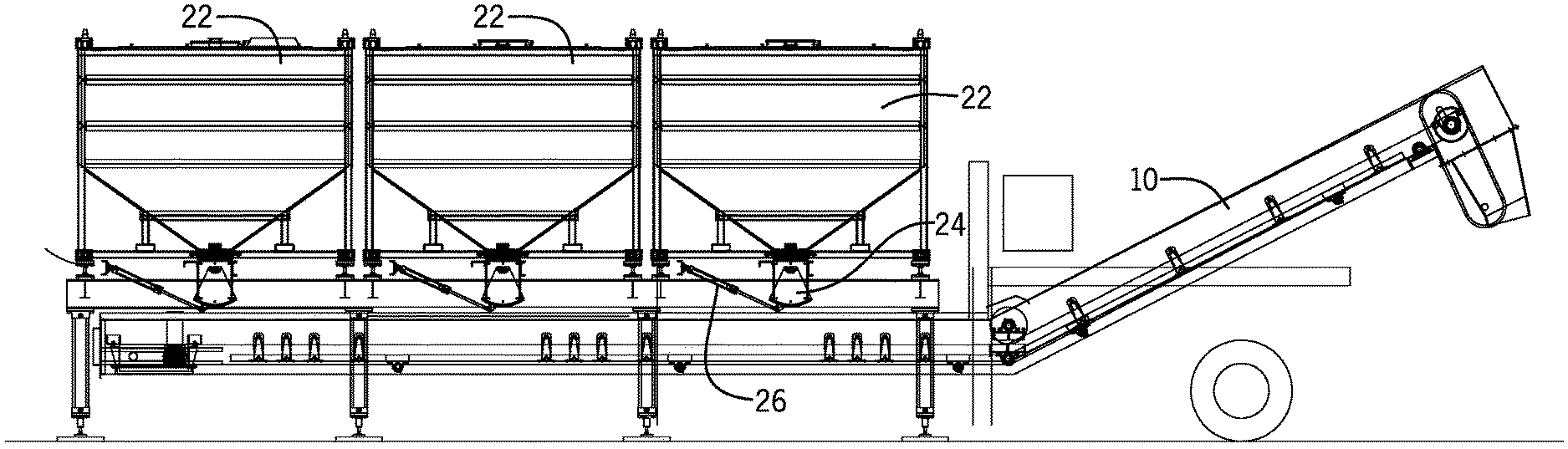
FIG. 1 illustrates an existing piece of equipment that is used on a large number of fracking well sites to convey a proppant, such as frac sand, to a mixing location. The existing piece of equipment is referred to as a T-belt conveyor 10. The T-belt conveyor 10 includes a pair of moving conveyor belts 12 that extend from a first end 14 to a second end 16 of a trailer 18. The trailer 18 includes multiple loading bays that each include a pair of loading hoppers 20 that each includes a sloping inner wall to direct the proppant material onto one of the conveyor belts 12 to allow the proppant material to be discharged by the pair of moving conveyor belts 12. Thus, the three-bay conveyor 10 includes six hoppers that can be separately loaded as will be discussed below.
Typically, the trailer 18 does not move from a position at the fracking well site once in positon. Although the T-belt conveyor 10 shown in the drawing figures includes two conveyor belts 12, other T-belt conveyors exist that include only a single moving conveyor belt. In a single belt conveyor, the conveyor includes multiple loading hoppers that direct material onto the single moving conveyor belt. The support frame system and method of the present disclosure can be modified to be used with a T-belt conveyor that includes only a single moving conveyor belt.
FIGS. 2-6 illustrate a first embodiment of a system for positioning a series of six intermodal storage containers 22 oriented in two rows of three containers each above the T-belt conveyor 10. Each of the storage containers 22 stores a supply of material to be dispensed, such as fracking sand. As shown in FIG. 2, each of the storage containers 22 includes a box gate that feeds material to a controlled clam shell, slide gate, ladder gate or other similar discharge gate 24 that can be selectively opened and closed by a hydraulic cylinder 26. In the present embodiment, the box gate is manually controlled and opened to feed material to the clam shell discharge gate 24. Issued U.S. Pat. No. 9,758,082 discloses the configuration of an example of a storage container 22 and is incorporated herein by reference. The system of the present disclosure could be used with other storage containers as well.
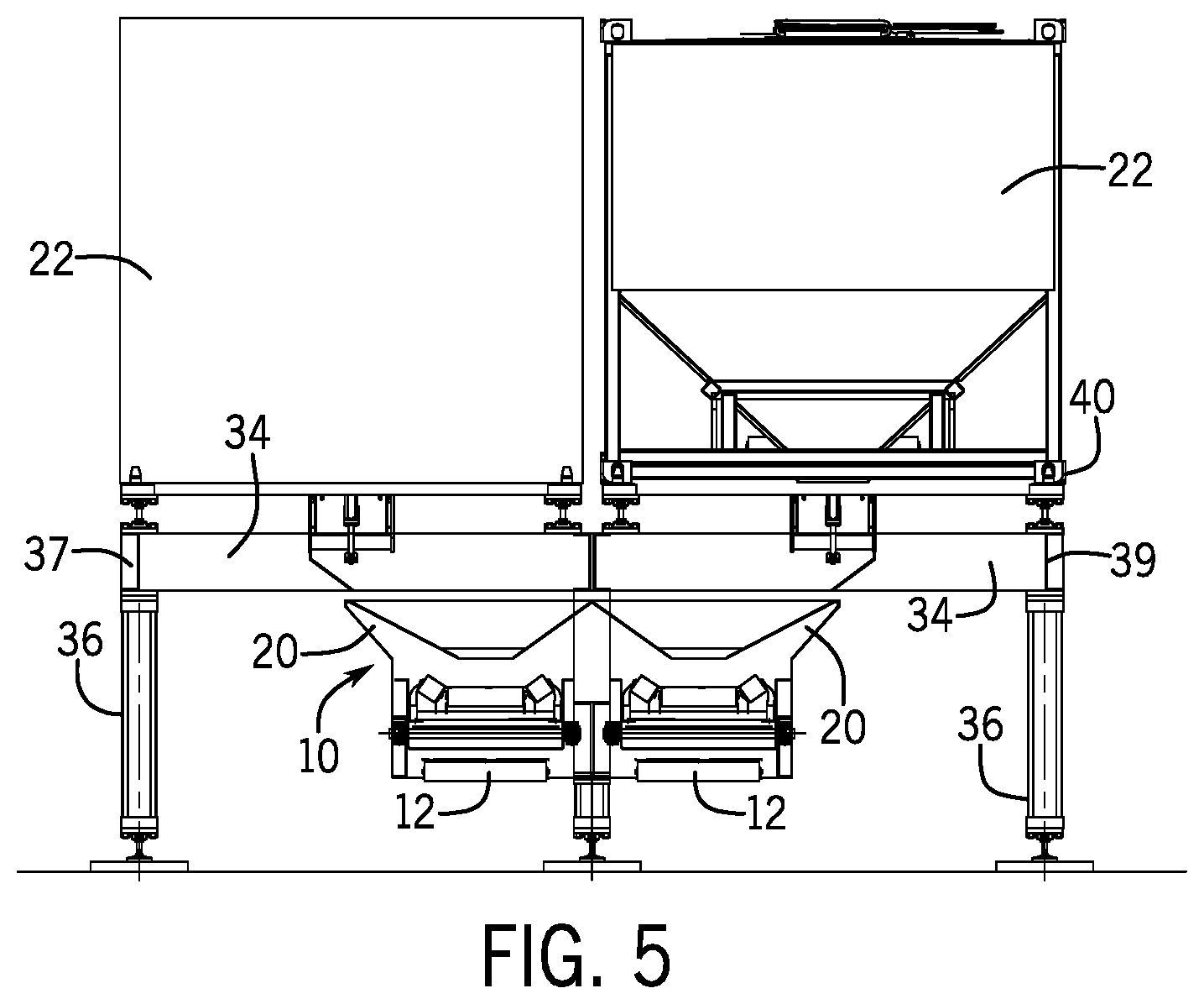
In the embodiment shown in FIG. 2, a first row of three individual storage containers 22 are positioned above each of the loading hoppers 20, referred to in the drawing figure as Bay One, Bay Two and Bay Three, of the T-belt conveyor. A second row of storage containers 22 are aligned with the first row (see FIG. 5) such that a storage container is aligned with each hopper for each of the two spaced conveyer belts. Thus, as shown in FIG. 5, two rows of storage containers 22 can be positioned adjacent to each other to discharge the stored material onto the conveyor belts 12 of the T-belt conveyor 10. Each of the storage containers 22 discharges material from a discharge gate 24 into the respective hopper 20 of the T-belt conveyor 10.
Referring back to FIG. 3, the first embodiment includes a support frame 28 that is positioned over the trailer of the T-belt conveyor 10 to support the six individual storage containers. The support frame 28 in the embodiments shown in FIG. 3 is formed from two separate bridge sections 30 that come together along a center beam 32. FIG. 4 shows one of two bridge sections 30. Each of the bridge sections 30 includes a plurality of cross supports 34 that are joined by a side beam 35. As shown in FIGS. 5 and 6, each of the horizontal cross supports 34 extends past the side edge of the conveyor 10 and includes an outer support leg 36 to support the horizontal cross support on the ground. As illustrated in FIG. 6, a center support leg 38 provides support along the center joint between the two bridge sections 30 of the support frame 28. The cross supports 34 of the pair of bridge sections 30 combine to define a first end 37 and a second end 39 that are each spaced from the sides of the conveyor 10.
In the embodiments shown in FIGS. 5 and 6, each of the storage containers 22 is supported at its four corners by a separate load cell 40. The load cells 40 each generate an electronic signal related to the amount of load sensed by the load cell 40. The four load cells 40 located at the corners of the storage container allow for the automated monitoring of the weight of the material contained within the storage container 22 both before discharge and as the material is discharged through the gate and onto the conveyer belt 12. Once the automated sensing system determines that the container 22 is empty, the container is removed and replaced with a full container. Additional box empty/full status indicators could be employed in the belt hopper either in addition to the load cells 40 or without the load cells. Such status indicators could include a photocell, acoustic transmission/reflection sensors, a rotating impeller within the hopper that rotates and which rotation is halted by the presence of proppant in the hopper or other methods of determining if the storage container contains proppant material.
FIGS. 7 and 8 illustrate a second embodiment of the storage container mounting system of the present disclosure. In the second embodiment, as shown in FIG. 7, a support frame 42 again spans over the width of the T-belt conveyor 10. However, in the embodiment shown in FIGS. 7 and 8, the support frame 42 includes a series of spaced cross supports 44 joined by the pair of spaced side beams 45. Each of the cross supports 44 includes an outrigger 46 located at each of its spaced first and second outer ends 51 and 53 respectively. The outriggers 46, as shown in FIG. 8, include an outer support leg 48 and a moveable beam 50. The moveable beam 50 can be extended to support the entire weight of the storage container 22 when the storage container 22 is supported as shown in FIG. 8.
Each of the moveable beams 50 can be extended such that the overall length of the cross support 44, including the moveable beams 50, can extend to the outer edge 49 of the storage container 22 as illustrated in FIG. 8. The outrigger moveable beam 50 will include one of the load cells as described above. As can be understood in FIGS. 7 and 8, the support frame 42 will include one more cross support 44 than the number of storage containers 22 that can be supported by the support frame 42. The series of cross supports 44 are supported on each of their ends by legs 52. In this manner, the support frame 42 is able to support six of the storage containers 22 in proper alignment to discharge material onto the T-belt conveyor 10.
FIGS. 9-10 illustrate a third embodiment of a support frame 60. The support frame 60 again spans over the width of the T-belt conveyor (not shown) and can support six of the intermodal storage containers. The support frame 60 shown in FIG. 9 includes a pair of side rails 62 that can be moved toward and away from each other through a series of expanding length cross supports 64. Each of the cross supports 64 includes an outer section 66 and an inner section 68. The inner section 68 can be extended into and out of the outer section 66 through an extension cylinder (not shown). The movement of the inner section 68 relative to the outer section 66 allows the width of the support frame 60 to be adjusted. The extension and retraction of the width of the support frame 60 allows the support frame 60 to be stored and transported in a retracted position and expanded to a size dictated by the T-belt conveyor.
FIG. 10 illustrates an outer extension frame 70 that is mounted to each of the vertical support legs 72. The extension frame 70 includes a horizontal support beam 74 as well as an angled support arm 76. The support arm 76 is mounted at its inner end about a pivot bracket 78 that receives a pivot pin 80. The horizontal support beam 74 also pivots about a pivot pin 82. In this manner, the entire extension frame 70 can rotate from the extended position shown in FIG. 10 to a retracted position.
When the extension frame 70 is in the extended position shown in FIG. 10, the horizontal support beam 74 can support the outer corner of a storage container. A load cell pad 84 is shown in FIG. 10 that supports one corner of one of the storage containers. As illustrated in FIG. 10, the support leg 72 includes an extendable portion 86 that is connected to an internal cylinder 88 to adjust the length of the support leg 72.
FIGS. 11-19 illustrate yet another alternate embodiment of the support system of the present disclosure for supporting a series of intermodal storage containers 22 above a T-belt conveyor 10. As illustrated in FIG. 11, the T-belt conveyor 10 is shown aligned with six of the storage container 22 each mounted to a support frame assembly 100. As shown in FIG. 12, the support frame assembly 100 is comprised of three separate tables 102 that each span over the width of the T-belt conveyor 10. Each of the tables 102 supports a pair of storage containers 22 in a side-by-side relationship and can be separately moved and positioned. Each of the individual tables 102 includes a pair of cross supports 104 joined to each other by a pair of side beams 106. As illustrated in FIG. 13, when the storage containers 22 are mounted to the support tables 102, the discharge gate 108 of each of the containers is aligned with one of the discharge hoppers 20 of the T-belt conveyor. As in the past embodiments, a clam shell discharge gate 24 controls the flow of material from the storage container onto the T-belt conveyor 10. FIG. 14 illustrates the position of the storage containers 22 allowing the cross support 104 of each of the support tables 102. Each of the cross supports 104 is supported by an outer leg 110. As illustrated in FIG. 15, material discharged from the clam shell discharge gate is directed into the hopper 20 and onto the conveyer belt 12.
Although not shown in the drawing figures, each of the embodiments illustrated includes a control panel that controls the operation of the conveyor frame mounted discharge gate and receives information from the individual load cells that monitor the weight of the material remaining in the storage containers. In a proposed alternative design, the control panel could also control the opening and closing of the box gate located on each of the storage containers. In the embodiment shown and described, the box gate for each storage container is manually opened and closed. The control panel allows a user to selectively control the discharge rate of material from each of the storage containers by controlling flow through the conveyor frame mounted discharge gate or by adjusting conveyor belt speed, and can indicate when any one of the storage containers has been fully discharged.
FIG. 20 includes a representation of what an operator might see on a frame mounted touch screen control device. This touch screen information can also be transmitted to a smart device (phone, ipad, etc) or to the computer van where most of the functions of the fracking job are being monitored by the fracking crew. The touch screen display 119 includes an indicator circle 120 that includes a color indicator. When the indicator circle 120 is green, this color indicator signifies that proppant, such as sand, is in the storage container. This status could be determined by a variety of devices, such as a rotating impeller device that sense proppant in the container. If the impeller, which is in the conveyor mounted hopper, is free to turn, that means there is no proppant in that hopper, implying that the box has emptied. The indicator circle 120 would then turn red. If there is proppant in that hopper, the proppant encloses and binds the impeller from turning, so the indicator circle 120 turns green, informing the user that there is still sand in the hopper and box. In such an embodiment, the impeller is turned by a low torque electric motor and the output of that motor is sent to the control panel telling it whether the impeller is turning.
As shown in FIG. 20, the output of the load cells is used to determine the number of current pounds of sand in the container, which is numerically displayed as shown by reference number 121. In addition, estimated sand level is shown by the gauge 122 and the current position of the discharge gate between fully open and fully closed conditions is shown by the gauge 124. Other information could also be included on the touch screen display 119 as desired.
* * * * *
References
-
arrowsupinc.com/product-pages/AUI_8.5x11_Jumbo_Flyer_01-2014_Final.pdf
-
monstertanksinc.com/sand-monster.html
-
reusables.org/2787/general/member-spotlight-john-allegretti-president-ceo-arrows-up-inc
-
-
-
solarisoilfield.com/solaris-solutions/mobile-sand-silo-system
D00000
D00001
D00002
D00003
D00004
D00005
D00006
D00007
D00008
D00009
D00010
D00011
D00012

D00013

D00014

D00015

D00016

D00017

D00018

XML
uspto.report is an independent third-party trademark research tool that is not affiliated, endorsed, or sponsored by the United States Patent and Trademark Office (USPTO) or any other governmental organization. The information provided by uspto.report is based on publicly available data at the time of writing and is intended for informational purposes only.
While we strive to provide accurate and up-to-date information, we do not guarantee the accuracy, completeness, reliability, or suitability of the information displayed on this site. The use of this site is at your own risk. Any reliance you place on such information is therefore strictly at your own risk.
All official trademark data, including owner information, should be verified by visiting the official USPTO website at www.uspto.gov. This site is not intended to replace professional legal advice and should not be used as a substitute for consulting with a legal professional who is knowledgeable about trademark law.