Regional oximetry sensor
Al-Ali , et al.
U.S. patent number 10,617,335 [Application Number 15/891,910] was granted by the patent office on 2020-04-14 for regional oximetry sensor. This patent grant is currently assigned to Masimo Corporation. The grantee listed for this patent is MASIMO CORPORATION. Invention is credited to Yassir Abdul-Hafiz, Ammar Al-Ali, Kevin Forrest, Sujin Hwang, Pete Mangosing, Walter M. Weber.
View All Diagrams
| United States Patent | 10,617,335 |
| Al-Ali , et al. | April 14, 2020 |
Regional oximetry sensor
Abstract
A regional oximetry sensor has a sensor head attachable to a patient skin surface so as to transmit optical radiation into the skin and receive that optical radiation after attenuation by blood flow within the skin. The sensor includes windows that press into the skin to maximize optical transmission. A stem extending from the sensor head transmits electrical signals between the sensor head and an attached cable. In a peel resistant configuration, the stem is terminated interior to the sensor head and away from a sensor head edge so as to define feet along either side of the stem distal the stem termination. The stem interior termination transforms a peel load on a sensor head adhesive to less challenging tension and shear loads on the sensor head adhesive.
| Inventors: | Al-Ali; Ammar (San Juan Capistrano, CA), Forrest; Kevin (Rancho Santa Margarita, CA), Abdul-Hafiz; Yassir (Irvine, CA), Weber; Walter M. (Laguna Hills, CA), Mangosing; Pete (Santa Ana, CA), Hwang; Sujin (Irvine, CA) | ||||||||||
|---|---|---|---|---|---|---|---|---|---|---|---|
| Applicant: |
|
||||||||||
| Assignee: | Masimo Corporation (Irvine,
CA) |
||||||||||
| Family ID: | 51842849 | ||||||||||
| Appl. No.: | 15/891,910 | ||||||||||
| Filed: | February 8, 2018 |
Prior Publication Data
| Document Identifier | Publication Date | |
|---|---|---|
| US 20180168491 A1 | Jun 21, 2018 | |
Related U.S. Patent Documents
| Application Number | Filing Date | Patent Number | Issue Date | ||
|---|---|---|---|---|---|
| 14507620 | Oct 6, 2014 | ||||
| 62012170 | Jun 13, 2014 | ||||
| 61887878 | Oct 7, 2013 | ||||
| 61887856 | Oct 7, 2013 | ||||
| 61887883 | Oct 7, 2013 | ||||
| Current U.S. Class: | 1/1 |
| Current CPC Class: | A61B 5/742 (20130101); A61B 5/14552 (20130101); A61B 5/14553 (20130101); A61B 5/14542 (20130101); A61B 5/6833 (20130101); A61B 5/7275 (20130101); A61B 5/746 (20130101); A61B 5/1455 (20130101); A61B 2562/228 (20130101); H01R 13/5224 (20130101); A61B 5/14551 (20130101); A61B 2562/225 (20130101); A61B 2562/22 (20130101); H01R 2201/12 (20130101); A61B 2562/222 (20130101); A61B 2562/227 (20130101); A61B 5/14557 (20130101) |
| Current International Class: | A61B 5/1455 (20060101); A61B 5/00 (20060101); A61B 5/145 (20060101); H01R 13/52 (20060101) |
References Cited [Referenced By]
U.S. Patent Documents
| 4960128 | October 1990 | Gordon et al. |
| 4964408 | October 1990 | Hink et al. |
| 5041187 | August 1991 | Hink et al. |
| 5069213 | December 1991 | Polczynski |
| 5163438 | November 1992 | Gordon et al. |
| 5237994 | August 1993 | Goldberger |
| 5319355 | June 1994 | Russek |
| 5337744 | August 1994 | Branigan |
| 5341805 | August 1994 | Stavridi et al. |
| D353195 | December 1994 | Savage et al. |
| D353196 | December 1994 | Savage et al. |
| 5377676 | January 1995 | Vari et al. |
| D359546 | June 1995 | Savage et al. |
| 5431170 | July 1995 | Mathews |
| D361840 | August 1995 | Savage et al. |
| D362063 | September 1995 | Savage et al. |
| 5452717 | September 1995 | Branigan et al. |
| D363120 | October 1995 | Savage et al. |
| 5456252 | October 1995 | Vari et al. |
| 5479934 | January 1996 | Imran |
| 5482036 | January 1996 | Diab et al. |
| 5490505 | February 1996 | Diab et al. |
| 5494043 | February 1996 | O'Sullivan et al. |
| 5533511 | July 1996 | Kaspari et al. |
| 5534851 | July 1996 | Russek |
| 5561275 | October 1996 | Savage et al. |
| 5562002 | October 1996 | Lalin |
| 5590649 | January 1997 | Caro et al. |
| 5602924 | February 1997 | Durand et al. |
| 5632272 | May 1997 | Diab et al. |
| 5632273 | May 1997 | Suzuki |
| 5638816 | June 1997 | Kiani-Azarbayjany et al. |
| 5638818 | June 1997 | Diab et al. |
| 5645440 | July 1997 | Tobler et al. |
| 5685299 | November 1997 | Diab et al. |
| D393830 | April 1998 | Tobler et al. |
| 5743262 | April 1998 | Lepper, Jr. et al. |
| 5758644 | June 1998 | Diab et al. |
| 5760910 | June 1998 | Lepper, Jr. et al. |
| 5769785 | June 1998 | Diab et al. |
| 5782757 | July 1998 | Diab et al. |
| 5785659 | July 1998 | Caro et al. |
| 5791347 | August 1998 | Flaherty et al. |
| 5810734 | September 1998 | Caro et al. |
| 5823950 | October 1998 | Diab et al. |
| 5830131 | November 1998 | Caro et al. |
| 5833618 | November 1998 | Caro et al. |
| 5860919 | January 1999 | Kiani-Azarbayjany et al. |
| 5890929 | April 1999 | Mills et al. |
| 5904654 | May 1999 | Wohltmann et al. |
| 5919134 | July 1999 | Diab |
| 5934925 | August 1999 | Tobler et al. |
| 5940182 | August 1999 | Lepper, Jr. et al. |
| 5995855 | November 1999 | Kiani et al. |
| 5997343 | December 1999 | Mills et al. |
| 6002952 | December 1999 | Diab et al. |
| 6011986 | January 2000 | Diab et al. |
| 6027452 | February 2000 | Flaherty et al. |
| 6036642 | March 2000 | Diab et al. |
| 6045509 | April 2000 | Caro et al. |
| 6067462 | May 2000 | Diab et al. |
| 6081735 | June 2000 | Diab et al. |
| 6088607 | July 2000 | Diab et al. |
| 6110522 | August 2000 | Lepper, Jr. et al. |
| 6124597 | September 2000 | Shehada |
| 6128521 | October 2000 | Marro et al. |
| 6129675 | October 2000 | Jay |
| 6144868 | November 2000 | Parker |
| 6151516 | November 2000 | Kiani-Azarbayjany et al. |
| 6152754 | November 2000 | Gerhardt et al. |
| 6157850 | December 2000 | Diab et al. |
| 6165005 | December 2000 | Mills et al. |
| 6184521 | February 2001 | Coffin, IV et al. |
| 6206830 | March 2001 | Diab et al. |
| 6229856 | May 2001 | Diab et al. |
| 6232609 | May 2001 | Snyder et al. |
| 6236872 | May 2001 | Diab et al. |
| 6241683 | June 2001 | Macklem et al. |
| 6253097 | June 2001 | Aronow et al. |
| 6256523 | July 2001 | Diab et al. |
| 6263222 | July 2001 | Diab et al. |
| 6278522 | August 2001 | Lepper, Jr. et al. |
| 6280213 | August 2001 | Tobler et al. |
| 6285896 | September 2001 | Tobler et al. |
| 6301493 | October 2001 | Marro et al. |
| 6317627 | November 2001 | Ennen et al. |
| 6321100 | November 2001 | Parker |
| 6325761 | December 2001 | Jay |
| 6334065 | December 2001 | Al-Ali et al. |
| 6343224 | January 2002 | Parker |
| 6349228 | February 2002 | Kiani et al. |
| 6360114 | March 2002 | Diab et al. |
| 6368283 | April 2002 | Xu et al. |
| 6371921 | April 2002 | Caro et al. |
| 6377829 | April 2002 | Al-Ali |
| 6388240 | May 2002 | Schulz et al. |
| 6397091 | May 2002 | Diab et al. |
| 6430437 | August 2002 | Marro |
| 6430525 | August 2002 | Weber et al. |
| 6463311 | October 2002 | Diab |
| 6470199 | October 2002 | Kopotic et al. |
| 6501975 | December 2002 | Diab et al. |
| 6505059 | January 2003 | Kollias et al. |
| 6515273 | February 2003 | Al-Ali |
| 6519487 | February 2003 | Parker |
| 6525386 | February 2003 | Mills et al. |
| 6526300 | February 2003 | Kiani et al. |
| 6541756 | April 2003 | Schulz et al. |
| 6542764 | April 2003 | Al-Ali et al. |
| 6580086 | June 2003 | Schulz et al. |
| 6584336 | June 2003 | Ali et al. |
| 6595316 | July 2003 | Cybulski et al. |
| 6597932 | July 2003 | Tian et al. |
| 6597933 | July 2003 | Kiani et al. |
| 6606511 | August 2003 | Ali et al. |
| 6632181 | October 2003 | Flaherty et al. |
| 6639668 | October 2003 | Trepagnier |
| 6640116 | October 2003 | Diab |
| 6643530 | November 2003 | Diab et al. |
| 6650917 | November 2003 | Diab et al. |
| 6654624 | November 2003 | Diab et al. |
| 6658276 | December 2003 | Kiani et al. |
| 6661161 | December 2003 | Lanzo et al. |
| 6671531 | December 2003 | Ai-Ali et al. |
| 6678543 | January 2004 | Diab et al. |
| 6684090 | January 2004 | Ali et al. |
| 6684091 | January 2004 | Parker |
| 6697656 | February 2004 | Ai-Ali |
| 6697657 | February 2004 | Shehada et al. |
| 6697658 | February 2004 | Al-Ali |
| RE38476 | March 2004 | Diab et al. |
| 6699194 | March 2004 | Diab et al. |
| 6714804 | March 2004 | Al-Ali et al. |
| RE38492 | April 2004 | Diab et al. |
| 6721582 | April 2004 | Trepagnier et al. |
| 6721585 | April 2004 | Parker |
| 6725075 | April 2004 | Al-Ali |
| 6728560 | April 2004 | Kollias et al. |
| 6735459 | May 2004 | Parker |
| 6745060 | June 2004 | Diab et al. |
| 6745061 | June 2004 | Hicks et al. |
| 6760607 | July 2004 | Al-Ali |
| 6770028 | August 2004 | Ali et al. |
| 6771994 | August 2004 | Kiani et al. |
| 6792300 | September 2004 | Diab et al. |
| 6813511 | November 2004 | Diab et al. |
| 6816741 | November 2004 | Diab |
| 6822564 | November 2004 | Al-Ali |
| 6826419 | November 2004 | Diab et al. |
| 6830711 | December 2004 | Mills et al. |
| 6850787 | February 2005 | Weber et al. |
| 6850788 | February 2005 | Al-Ali |
| 6852083 | February 2005 | Caro et al. |
| 6861639 | March 2005 | Al-Ali |
| 6898452 | May 2005 | Al-Ali et al. |
| 6920345 | July 2005 | Al-Ali et al. |
| 6931268 | August 2005 | Kiani-Azarbayjany et al. |
| 6934570 | August 2005 | Kiani et al. |
| 6939305 | September 2005 | Flaherty et al. |
| 6943348 | September 2005 | Coffin, IV |
| 6950687 | September 2005 | Al-Ali |
| 6961598 | November 2005 | Diab |
| 6970792 | November 2005 | Diab |
| 6979812 | December 2005 | Al-Ali |
| 6985764 | January 2006 | Mason et al. |
| 6993371 | January 2006 | Kiani et al. |
| 6996427 | February 2006 | Ali et al. |
| 7003338 | February 2006 | Weber et al. |
| 7003339 | February 2006 | Diab et al. |
| 7015451 | March 2006 | Dalke et al. |
| 7024233 | April 2006 | Ali et al. |
| 7027849 | April 2006 | Al-Ali |
| 7030749 | April 2006 | Al-Ali |
| 7039449 | May 2006 | Al-Ali |
| 7041060 | May 2006 | Flaherty et al. |
| 7044918 | May 2006 | Diab |
| 7067893 | June 2006 | Mills et al. |
| 7096052 | August 2006 | Mason et al. |
| 7096054 | August 2006 | Abdul-Hafiz et al. |
| 7132641 | November 2006 | Schulz et al. |
| 7142901 | November 2006 | Kiani et al. |
| 7149561 | December 2006 | Diab |
| 7186966 | March 2007 | Al-Ali |
| 7190261 | March 2007 | Al-Ali |
| 7215984 | May 2007 | Diab |
| 7215986 | May 2007 | Diab |
| 7221971 | May 2007 | Diab |
| 7225006 | May 2007 | Al-Ali et al. |
| 7225007 | May 2007 | Al-Ali |
| RE39672 | June 2007 | Shehada et al. |
| 7239905 | July 2007 | Kiani-Azarbayjany et al. |
| 7245953 | July 2007 | Parker |
| 7254429 | August 2007 | Schurman et al. |
| 7254431 | August 2007 | Al-Ali |
| 7254433 | August 2007 | Diab et al. |
| 7254434 | August 2007 | Schulz et al. |
| 7272425 | September 2007 | Al-Ali |
| 7274955 | September 2007 | Kiani et al. |
| D554263 | October 2007 | Ai-Ali |
| 7280858 | October 2007 | Al-Ali et al. |
| 7289835 | October 2007 | Mansfield et al. |
| 7292883 | November 2007 | De Felice et al. |
| 7295866 | November 2007 | Al-Ali |
| 7328053 | February 2008 | Diab et al. |
| 7332784 | February 2008 | Mills et al. |
| 7340287 | March 2008 | Mason et al. |
| 7341559 | March 2008 | Schulz et al. |
| 7343186 | March 2008 | Lamego et al. |
| D566282 | April 2008 | Al-Ali et al. |
| 7355512 | April 2008 | Al-Ali |
| 7356365 | April 2008 | Schurman |
| 7371981 | May 2008 | Abdul-Hafiz |
| 7373193 | May 2008 | Al-Ali et al. |
| 7373194 | May 2008 | Weber et al. |
| 7376453 | May 2008 | Diab et al. |
| 7377794 | May 2008 | Al-Ali et al. |
| 7377899 | May 2008 | Weber et al. |
| 7383070 | June 2008 | Diab et al. |
| 7415297 | August 2008 | Al-Ali et al. |
| 7428432 | September 2008 | Ali et al. |
| 7438683 | October 2008 | Al-Ali et al. |
| 7440787 | October 2008 | Diab |
| 7454240 | November 2008 | Diab et al. |
| 7467002 | December 2008 | Weber et al. |
| 7469157 | December 2008 | Diab et al. |
| 7471969 | December 2008 | Diab et al. |
| 7471971 | December 2008 | Diab et al. |
| 7483729 | January 2009 | Al-Ali et al. |
| 7483730 | January 2009 | Diab et al. |
| 7489958 | February 2009 | Diab et al. |
| 7496391 | February 2009 | Diab et al. |
| 7496393 | February 2009 | Diab et al. |
| D587657 | March 2009 | Al-Ali et al. |
| 7499741 | March 2009 | Diab et al. |
| 7499835 | March 2009 | Weber et al. |
| 7500950 | March 2009 | Al-Ali et al. |
| 7509154 | March 2009 | Diab et al. |
| 7509494 | March 2009 | Al-Ali |
| 7510849 | March 2009 | Schurman et al. |
| 7526328 | April 2009 | Diab et al. |
| 7530942 | May 2009 | Diab |
| 7530949 | May 2009 | Al Ali et al. |
| 7530955 | May 2009 | Diab et al. |
| 7563110 | July 2009 | Al-Ali et al. |
| 7596398 | September 2009 | Al-Ali et al. |
| 7618375 | November 2009 | Flaherty |
| D606659 | December 2009 | Kiani et al. |
| 7647083 | January 2010 | Al-Ali et al. |
| D609193 | February 2010 | Al-Ali et al. |
| D614305 | April 2010 | Al-Ali et al. |
| RE41317 | May 2010 | Parker |
| 7729733 | June 2010 | Al-Ali et al. |
| 7734320 | June 2010 | Al-Ali |
| 7761127 | July 2010 | Al-Ali et al. |
| 7761128 | July 2010 | Al-Ali et al. |
| 7764982 | July 2010 | Dalke et al. |
| D621516 | August 2010 | Kiani et al. |
| 7791155 | September 2010 | Diab |
| 7801581 | September 2010 | Diab |
| 7822452 | October 2010 | Schurman et al. |
| RE41912 | November 2010 | Parker |
| 7844313 | November 2010 | Kiani et al. |
| 7844314 | November 2010 | Al-Ali |
| 7844315 | November 2010 | Al-Ali |
| 7865222 | January 2011 | Weber et al. |
| 7873497 | January 2011 | Weber et al. |
| 7880606 | February 2011 | Al-Ali |
| 7880626 | February 2011 | Al-Ali et al. |
| 7891355 | February 2011 | Al-Ali et al. |
| 7894868 | February 2011 | Al-Ali et al. |
| 7899507 | March 2011 | Al-Ali et al. |
| 7899518 | March 2011 | Trepagnier et al. |
| 7904132 | March 2011 | Weber et al. |
| 7909772 | March 2011 | Popov et al. |
| 7910875 | March 2011 | Al-Ali |
| 7919713 | April 2011 | Al-Ali et al. |
| 7937128 | May 2011 | Al-Ali |
| 7937129 | May 2011 | Mason et al. |
| 7937130 | May 2011 | Diab et al. |
| 7941199 | May 2011 | Kiani |
| 7951086 | May 2011 | Flaherty et al. |
| 7957780 | June 2011 | Lamego et al. |
| 7962188 | June 2011 | Kiani et al. |
| 7962190 | June 2011 | Diab et al. |
| 7976472 | July 2011 | Kiani |
| 7988637 | August 2011 | Diab |
| 7990382 | August 2011 | Kiani |
| 7991446 | August 2011 | Al-Ali et al. |
| 8000761 | August 2011 | Al-Ali |
| 8008088 | August 2011 | Bellott et al. |
| RE42753 | September 2011 | Kiani-Azarbayjany et al. |
| 8019400 | September 2011 | Diab et al. |
| 8028701 | October 2011 | Al-Ali et al. |
| 8029765 | October 2011 | Bellott et al. |
| 8036727 | October 2011 | Schurman et al. |
| 8036728 | October 2011 | Diab et al. |
| 8046040 | October 2011 | Ali et al. |
| 8046041 | October 2011 | Diab et al. |
| 8046042 | October 2011 | Diab et al. |
| 8048040 | November 2011 | Kiani |
| 8050728 | November 2011 | Al-Ali et al. |
| RE43169 | February 2012 | Parker |
| 8118620 | February 2012 | Al-Ali et al. |
| 8126528 | February 2012 | Diab et al. |
| 8128572 | March 2012 | Diab et al. |
| 8130105 | March 2012 | Al-Ali et al. |
| 8145287 | March 2012 | Diab et al. |
| 8150487 | April 2012 | Diab et al. |
| 8175672 | May 2012 | Parker |
| 8180420 | May 2012 | Diab et al. |
| 8182443 | May 2012 | Kiani |
| 8185180 | May 2012 | Diab et al. |
| 8190223 | May 2012 | Al-Ali et al. |
| 8190227 | May 2012 | Diab et al. |
| 8203438 | June 2012 | Kiani et al. |
| 8203704 | June 2012 | Merritt et al. |
| 8204566 | June 2012 | Schurman et al. |
| 8219172 | July 2012 | Schurman et al. |
| 8224411 | July 2012 | Al-Ali et al. |
| 8228181 | July 2012 | Al-Ali |
| 8229533 | July 2012 | Diab et al. |
| 8233955 | July 2012 | Al-Ali et al. |
| 8244325 | August 2012 | Al-Ali et al. |
| 8255026 | August 2012 | Al-Ali |
| 8255027 | August 2012 | Al-Ali et al. |
| 8255028 | August 2012 | Al-Ali et al. |
| 8260577 | September 2012 | Weber et al. |
| 8265723 | September 2012 | McHale et al. |
| 8274360 | September 2012 | Sampath et al. |
| 8301217 | October 2012 | Al-Ali et al. |
| 8306596 | November 2012 | Schurman et al. |
| 8310336 | November 2012 | Muhsin et al. |
| 8315683 | November 2012 | Al-Ali et al. |
| RE43860 | December 2012 | Parker |
| 8337403 | December 2012 | Al-Ali et al. |
| 8346330 | January 2013 | Lamego |
| 8353842 | January 2013 | Al-Ali et al. |
| 8355766 | January 2013 | MacNeish, III et al. |
| 8359080 | January 2013 | Diab et al. |
| 8364223 | January 2013 | Al-Ali et al. |
| 8364226 | January 2013 | Diab et al. |
| 8374665 | February 2013 | Lamego |
| 8385995 | February 2013 | Al-ali et al. |
| 8385996 | February 2013 | Smith et al. |
| 8388353 | March 2013 | Kiani et al. |
| 8399822 | March 2013 | Al-Ali |
| 8401602 | March 2013 | Kiani |
| 8405608 | March 2013 | Al-Ali et al. |
| 8414499 | April 2013 | Al-Ali et al. |
| 8418524 | April 2013 | Al-Ali |
| 8423106 | April 2013 | Lamego et al. |
| 8428967 | April 2013 | Olsen et al. |
| 8430817 | April 2013 | Al-Ali et al. |
| 8437825 | May 2013 | Dalvi et al. |
| 8455290 | June 2013 | Siskavich |
| 8457703 | June 2013 | Al-Ali |
| 8457707 | June 2013 | Kiani |
| 8463349 | June 2013 | Diab et al. |
| 8466286 | June 2013 | Bellot et al. |
| 8471713 | June 2013 | Poeze et al. |
| 8473020 | June 2013 | Kiani et al. |
| 8483787 | July 2013 | Al-Ali et al. |
| 8489364 | July 2013 | Weber et al. |
| 8498684 | July 2013 | Weber et al. |
| 8504128 | August 2013 | Blank et al. |
| 8509867 | August 2013 | Workman et al. |
| 8515509 | August 2013 | Bruinsma et al. |
| 8523781 | September 2013 | Al-Ali |
| 8529301 | September 2013 | Al-Ali et al. |
| 8532727 | September 2013 | Ali et al. |
| 8532728 | September 2013 | Diab et al. |
| D692145 | October 2013 | Al-Ali et al. |
| 8547209 | October 2013 | Kiani et al. |
| 8548548 | October 2013 | Al-Ali |
| 8548549 | October 2013 | Schurman et al. |
| 8548550 | October 2013 | Al-Ali et al. |
| 8560032 | October 2013 | Al-Ali et al. |
| 8560034 | October 2013 | Diab et al. |
| 8570167 | October 2013 | Al-Ali |
| 8570503 | October 2013 | Vo et al. |
| 8571617 | October 2013 | Reichgott et al. |
| 8571618 | October 2013 | Lamego et al. |
| 8571619 | October 2013 | Ai-Ali et al. |
| 8584345 | October 2013 | Al-Ali et al. |
| 8577431 | November 2013 | Lamego et al. |
| 8581732 | November 2013 | Al-Ali et al. |
| 8588880 | November 2013 | Abdul-Hafiz et al. |
| 8600467 | December 2013 | Al-Ali et al. |
| 8606342 | December 2013 | Diab |
| 8626255 | January 2014 | Al-Ali et al. |
| 8630691 | January 2014 | Lamego et al. |
| 8634889 | January 2014 | Al-Ali et al. |
| 8641631 | February 2014 | Sierra et al. |
| 8652060 | February 2014 | Al-Ali |
| 8663107 | March 2014 | Kiani |
| 8666468 | March 2014 | Al-Ali |
| 8667967 | March 2014 | Al-Ali et al. |
| 8670811 | March 2014 | O'Reilly |
| 8670814 | March 2014 | Diab et al. |
| 8676286 | March 2014 | Weber et al. |
| 8682407 | March 2014 | Al-Ali |
| RE44823 | April 2014 | Parker |
| RE44875 | April 2014 | Kiani et al. |
| 8690799 | April 2014 | Telfort et al. |
| 8700112 | April 2014 | Kiani |
| 8702627 | April 2014 | Telfort et al. |
| 8706179 | April 2014 | Parker |
| 8712494 | April 2014 | MacNeish, III et al. |
| 8715206 | May 2014 | Telfort et al. |
| 8718735 | May 2014 | Lamego et al. |
| 8718737 | May 2014 | Diab et al. |
| 8718738 | May 2014 | Blank et al. |
| 8720249 | May 2014 | Al-Ali |
| 8721541 | May 2014 | Al-Ali et al. |
| 8721542 | May 2014 | Al-Ali et al. |
| 8723677 | May 2014 | Kiani |
| 8740792 | June 2014 | Kiani et al. |
| 8754776 | June 2014 | Poeze et al. |
| 8755535 | June 2014 | Telfort et al. |
| 8755856 | June 2014 | Diab et al. |
| 8755872 | June 2014 | Marinow |
| 8761850 | June 2014 | Lamego |
| 8764671 | July 2014 | Kiani |
| 8768423 | July 2014 | Shakespeare et al. |
| 8771204 | July 2014 | Telfort et al. |
| 8777634 | July 2014 | Kiani et al. |
| 8781543 | July 2014 | Diab et al. |
| 8781544 | July 2014 | Al-Ali et al. |
| 8781549 | July 2014 | Al-Ali et al. |
| 8788003 | July 2014 | Schurman et al. |
| 8790268 | July 2014 | Al-Ali |
| 8801613 | August 2014 | Al-Ali et al. |
| 8821397 | September 2014 | Al-Ali et al. |
| 8821415 | September 2014 | Al-Ali et al. |
| 8830449 | September 2014 | Lamego et al. |
| 8831700 | September 2014 | Schurman et al. |
| 8840549 | September 2014 | Al-Ali et al. |
| 8847740 | September 2014 | Kiani et al. |
| 8849365 | September 2014 | Smith et al. |
| 8852094 | October 2014 | Al-Ali et al. |
| 8852994 | October 2014 | Wojtczuk et al. |
| 8868147 | October 2014 | Stippick et al. |
| 8868150 | October 2014 | Al-Ali et al. |
| 8870792 | October 2014 | Al-Ali et al. |
| 8886271 | November 2014 | Kiani et al. |
| 8888539 | November 2014 | Al-Ali et al. |
| 8888708 | November 2014 | Diab et al. |
| 8892180 | November 2014 | Weber et al. |
| 8897847 | November 2014 | Al-Ali |
| 8909310 | December 2014 | Lamego et al. |
| 8911377 | December 2014 | Al-Ali |
| 8912909 | December 2014 | Al-Ali et al. |
| 8920317 | December 2014 | Al-Ali et al. |
| 8921699 | December 2014 | Al-Ali et al. |
| 8922382 | December 2014 | Al-Ali et al. |
| 8929964 | January 2015 | Al-Ali et al. |
| 8942777 | January 2015 | Diab et al. |
| 8948834 | February 2015 | Diab et al. |
| 8948835 | February 2015 | Diab |
| 8965471 | February 2015 | Lamego |
| 8983564 | March 2015 | Al-Ali |
| 8989831 | March 2015 | Al-Ali et al. |
| 8996085 | March 2015 | Kiani et al. |
| 8998809 | April 2015 | Kiani |
| 9028429 | May 2015 | Telfort et al. |
| 9037207 | May 2015 | Al-Ali et al. |
| 9060721 | June 2015 | Reichgott et al. |
| 9066666 | June 2015 | Kiani |
| 9066680 | June 2015 | Al-Ali et al. |
| 9072474 | July 2015 | Al-Ali et al. |
| 9078560 | July 2015 | Schurman et al. |
| 9084569 | July 2015 | Weber et al. |
| 9095316 | August 2015 | Welch et al. |
| 9106038 | August 2015 | Telfort et al. |
| 9107625 | August 2015 | Telfort et al. |
| 9107626 | August 2015 | Al-Ali et al. |
| 9113831 | August 2015 | Al-Ali |
| 9113832 | August 2015 | Al-Ali |
| 9119595 | September 2015 | Lamego |
| 9131881 | September 2015 | Diab et al. |
| 9131882 | September 2015 | Al-Ali et al. |
| 9131883 | September 2015 | Al-Ali |
| 9131917 | September 2015 | Telfort et al. |
| 9138180 | September 2015 | Coverston et al. |
| 9138182 | September 2015 | Al-Ali et al. |
| 9138192 | September 2015 | Weber et al. |
| 9142117 | September 2015 | Muhsin et al. |
| 9153112 | October 2015 | Kiani et al. |
| 9153121 | October 2015 | Kiani et al. |
| 9161696 | October 2015 | Al-Ali et al. |
| 9161713 | October 2015 | Al-Ali et al. |
| 9167995 | October 2015 | Lamego et al. |
| 9176141 | November 2015 | Al-Ali et al. |
| 9186102 | November 2015 | Bruinsma et al. |
| 9192312 | November 2015 | Al-Ali |
| 9192329 | November 2015 | Al-Ali |
| 9192351 | November 2015 | Telfort et al. |
| 9195385 | November 2015 | Al-Ali et al. |
| 9211072 | December 2015 | Kiani |
| 9211095 | December 2015 | Al-Ali |
| 9218454 | December 2015 | Kiani et al. |
| 9226696 | January 2016 | Kiani |
| 9241662 | January 2016 | Al-Ali et al. |
| 9245668 | January 2016 | Vo et al. |
| 9259185 | February 2016 | Abdul-Hafiz et al. |
| 9267572 | February 2016 | Barker et al. |
| 9277880 | March 2016 | Poeze et al. |
| 9289167 | March 2016 | Diab et al. |
| 9295421 | March 2016 | Kiani et al. |
| 9307928 | April 2016 | Al-Ali et al. |
| 9323894 | April 2016 | Kiani |
| 9326712 | May 2016 | Kiani |
| 9333316 | May 2016 | Kiani |
| 9339220 | May 2016 | Lamego et al. |
| 9341565 | May 2016 | Lamego et al. |
| 9351673 | May 2016 | Diab et al. |
| 9351675 | May 2016 | Al-Ali et al. |
| 9364181 | June 2016 | Kiani et al. |
| 9368671 | June 2016 | Wojtczuk et al. |
| 9370325 | June 2016 | Al-Ali et al. |
| 9370326 | June 2016 | McHale et al. |
| 9370335 | June 2016 | Al-ali et al. |
| 9375185 | June 2016 | Ali et al. |
| 9386953 | July 2016 | Al-Ali |
| 9386961 | July 2016 | Al-Ali et al. |
| 9392945 | July 2016 | Al-Ali et al. |
| 9397448 | July 2016 | Al-Ali et al. |
| 9408542 | August 2016 | Kinast et al. |
| 9436645 | September 2016 | Al-Ali et al. |
| 9445759 | September 2016 | Lamego et al. |
| 9466919 | October 2016 | Kiani et al. |
| 9474474 | October 2016 | Lamego et al. |
| 9480422 | November 2016 | Al-Ali |
| 9480435 | November 2016 | Olsen |
| 9492110 | November 2016 | Al-Ali et al. |
| 9510779 | December 2016 | Poeze et al. |
| 9517024 | December 2016 | Kiani et al. |
| 9532722 | January 2017 | Lamego et al. |
| 9538949 | January 2017 | Al-Ali et al. |
| 9538980 | January 2017 | Telfort et al. |
| 9549696 | January 2017 | Lamego et al. |
| 9554737 | January 2017 | Schurman et al. |
| 9560996 | February 2017 | Kiani |
| 9560998 | February 2017 | Al-Ali et al. |
| 9566019 | February 2017 | Al-Ali et al. |
| 9579039 | February 2017 | Jansen et al. |
| 9591975 | March 2017 | Dalvi et al. |
| 9622692 | April 2017 | Lamego et al. |
| 9622693 | April 2017 | Diab |
| D788312 | May 2017 | Ai-Ali et al. |
| 9636055 | May 2017 | Al-Ali et al. |
| 9636056 | May 2017 | Al-Ali |
| 9649054 | May 2017 | Lamego et al. |
| 9662052 | May 2017 | Al-Ali et al. |
| 9668679 | June 2017 | Schurman et al. |
| 9668680 | June 2017 | Bruinsma et al. |
| 9668703 | June 2017 | Al-Ali |
| 9675286 | June 2017 | Diab |
| 9687160 | June 2017 | Kiani |
| 9693719 | July 2017 | Al-Ali et al. |
| 9693737 | July 2017 | Al-Ali |
| 9697928 | July 2017 | Al-Ali et al. |
| 9717425 | August 2017 | Kiani et al. |
| 9717458 | August 2017 | Lamego et al. |
| 9724016 | August 2017 | Al-Ali et al. |
| 9724024 | August 2017 | Al-Ali |
| 9724025 | August 2017 | Kiani et al. |
| 2003/0225323 | December 2003 | Kiani |
| 2007/0282478 | December 2007 | Al-Ali et al. |
| 2009/0247924 | October 2009 | Lamego et al. |
| 2009/0247984 | October 2009 | Lamego et al. |
| 2009/0275813 | November 2009 | Davis |
| 2009/0275844 | November 2009 | Al-Ali |
| 2009/0299157 | December 2009 | Telfort et al. |
| 2010/0004518 | January 2010 | Vo et al. |
| 2010/0030040 | February 2010 | Poeze et al. |
| 2010/0069725 | March 2010 | Al-Ali |
| 2010/0261979 | October 2010 | Kiani |
| 2010/0317936 | December 2010 | Al-Ali et al. |
| 2011/0001605 | January 2011 | Kiani et al. |
| 2011/0082711 | April 2011 | Poeze et al. |
| 2011/0105854 | May 2011 | Kiani et al. |
| 2011/0125060 | May 2011 | Telfort et al. |
| 2011/0172967 | July 2011 | Al-Ali et al. |
| 2011/0190600 | August 2011 | McKenna |
| 2011/0208015 | August 2011 | Welch et al. |
| 2011/0209915 | September 2011 | Telfort et al. |
| 2011/0213212 | September 2011 | Al-Ali |
| 2011/0230733 | September 2011 | Al-Ali |
| 2011/0237911 | September 2011 | Lamego et al. |
| 2011/0237969 | September 2011 | Eckerbom et al. |
| 2011/0288383 | November 2011 | Diab |
| 2012/0041316 | February 2012 | Al-Ali et al. |
| 2012/0046557 | February 2012 | Kiani |
| 2012/0059267 | March 2012 | Lamego et al. |
| 2012/0088984 | April 2012 | Al-Ali et al. |
| 2012/0116175 | May 2012 | Al-Ali et al. |
| 2012/0165629 | June 2012 | Merritt et al. |
| 2012/0179006 | July 2012 | Jansen et al. |
| 2012/0209082 | August 2012 | Al-Ali |
| 2012/0209084 | August 2012 | Olsen et al. |
| 2012/0227739 | September 2012 | Kiani |
| 2012/0253163 | October 2012 | Afanasewicz |
| 2012/0265039 | October 2012 | Kiani |
| 2012/0283524 | November 2012 | Kiani et al. |
| 2012/0286955 | November 2012 | Welch et al. |
| 2012/0296178 | November 2012 | Lamego et al. |
| 2012/0302894 | November 2012 | Diab et al. |
| 2012/0319816 | December 2012 | Al-Ali |
| 2012/0330112 | December 2012 | Lamego et al. |
| 2013/0023775 | January 2013 | Lamego et al. |
| 2013/0041591 | February 2013 | Lamego |
| 2013/0045685 | February 2013 | Kiani |
| 2013/0046204 | February 2013 | Lamego et al. |
| 2013/0060108 | March 2013 | Schurman et al. |
| 2013/0060147 | March 2013 | Welch et al. |
| 2013/0079610 | March 2013 | Al-Ali |
| 2013/0079618 | March 2013 | Sandmore |
| 2013/0096405 | April 2013 | Garfio |
| 2013/0096936 | April 2013 | Sampath et al. |
| 2013/0109935 | May 2013 | Al-Ali et al. |
| 2013/0162433 | June 2013 | Muhsin et al. |
| 2013/0178725 | July 2013 | O'Neil et al. |
| 2013/0178749 | July 2013 | Lamego |
| 2013/0190581 | July 2013 | Al-Ali et al. |
| 2013/0197328 | August 2013 | Diab et al. |
| 2013/0211214 | August 2013 | Olsen |
| 2013/0243021 | September 2013 | Siskavich |
| 2013/0253334 | September 2013 | Al-Ali et al. |
| 2013/0267804 | October 2013 | Al-Ali |
| 2013/0274571 | October 2013 | Diab et al. |
| 2013/0274572 | October 2013 | Al-Ali et al. |
| 2013/0278802 | October 2013 | Attar |
| 2013/0296672 | November 2013 | O'Neil et al. |
| 2013/0296713 | November 2013 | Al-Ali et al. |
| 2013/0317327 | November 2013 | Al-Ali et al. |
| 2013/0317370 | November 2013 | Dalvi et al. |
| 2013/0324808 | December 2013 | Al-Ali et al. |
| 2013/0324817 | December 2013 | Diab |
| 2013/0331660 | December 2013 | Al-Ali et al. |
| 2013/0331670 | December 2013 | Kiani |
| 2013/0338461 | December 2013 | Lamego et al. |
| 2014/0012100 | January 2014 | Al-Ali et al. |
| 2014/0025306 | January 2014 | Weber et al. |
| 2014/0031650 | January 2014 | Weber et al. |
| 2014/0034353 | February 2014 | Al-Ali et al. |
| 2014/0051952 | February 2014 | Reichgott et al. |
| 2014/0051953 | February 2014 | Lamego et al. |
| 2014/0051954 | February 2014 | Al-Ali et al. |
| 2014/0058230 | February 2014 | Abdul-Hafiz et al. |
| 2014/0058233 | February 2014 | Koyama et al. |
| 2014/0066783 | March 2014 | Kiani et al. |
| 2014/0073167 | March 2014 | Al-Ali et al. |
| 2014/0077956 | March 2014 | Sampath et al. |
| 2014/0081097 | March 2014 | Al-Ali et al. |
| 2014/0081100 | March 2014 | Muhsin et al. |
| 2014/0081175 | March 2014 | Telfort |
| 2014/0094667 | April 2014 | Schurman et al. |
| 2014/0100434 | April 2014 | Diab et al. |
| 2014/0114199 | April 2014 | Lamego et al. |
| 2014/0120564 | May 2014 | Workman et al. |
| 2014/0121482 | May 2014 | Merritt et al. |
| 2014/0121483 | May 2014 | Kiani |
| 2014/0125495 | May 2014 | Al-Ali |
| 2014/0127137 | May 2014 | Bellott et al. |
| 2014/0128696 | May 2014 | Al-Ali |
| 2014/0128699 | May 2014 | Al-Ali et al. |
| 2014/0129702 | May 2014 | Lamego et al. |
| 2014/0135588 | May 2014 | Al-Ali et al. |
| 2014/0142399 | May 2014 | Al-Ali et al. |
| 2014/0142401 | May 2014 | Al-Ali et al. |
| 2014/0142402 | May 2014 | Al-Ali et al. |
| 2014/0155712 | June 2014 | Lamego et al. |
| 2014/0163344 | June 2014 | Al-Ali |
| 2014/0163402 | June 2014 | Lamego et al. |
| 2014/0166076 | June 2014 | Kiani et al. |
| 2014/0171763 | June 2014 | Diab |
| 2014/0180038 | June 2014 | Kiani |
| 2014/0180154 | June 2014 | Sierra et al. |
| 2014/0180160 | June 2014 | Brown et al. |
| 2014/0187973 | July 2014 | Brown et al. |
| 2014/0194709 | July 2014 | Al-Ali et al. |
| 2014/0194711 | July 2014 | Al-Ali |
| 2014/0194766 | July 2014 | Al-Ali et al. |
| 2014/0200420 | July 2014 | Al-Ali |
| 2014/0200422 | July 2014 | Weber et al. |
| 2014/0206963 | July 2014 | Al-Ali |
| 2014/0213864 | July 2014 | Abdul-Hafiz et al. |
| 2014/0243627 | August 2014 | Diab et al. |
| 2014/0266790 | September 2014 | Al-Ali et al. |
| 2014/0275808 | September 2014 | Poeze et al. |
| 2014/0275835 | September 2014 | Lamego et al. |
| 2014/0275871 | September 2014 | Lamego et al. |
| 2014/0275872 | September 2014 | Merritt et al. |
| 2014/0275881 | September 2014 | Lamego et al. |
| 2014/0275932 | September 2014 | Zadig |
| 2014/0276115 | September 2014 | Dalvi et al. |
| 2014/0288400 | September 2014 | Diab et al. |
| 2014/0296664 | October 2014 | Bruinsma et al. |
| 2014/0303520 | October 2014 | Telfort et al. |
| 2014/0309506 | October 2014 | Lamego et al. |
| 2014/0309559 | October 2014 | Telfort et al. |
| 2014/0316217 | October 2014 | Purdon et al. |
| 2014/0316218 | October 2014 | Purdon et al. |
| 2014/0316228 | October 2014 | Blank et al. |
| 2014/0323825 | October 2014 | Al-Ali et al. |
| 2014/0323897 | October 2014 | Brown et al. |
| 2014/0323898 | October 2014 | Purdon et al. |
| 2014/0330092 | November 2014 | Al-Ali et al. |
| 2014/0330098 | November 2014 | Merritt et al. |
| 2014/0330099 | November 2014 | Al-Ali et al. |
| 2014/0336481 | November 2014 | Shakespeare et al. |
| 2014/0357966 | December 2014 | Al-Ali et al. |
| 2015/0005600 | January 2015 | Blank et al. |
| 2015/0011907 | January 2015 | Purdon et al. |
| 2015/0012231 | January 2015 | Poeze et al. |
| 2015/0025406 | January 2015 | Al-Ali |
| 2015/0032029 | January 2015 | Al-Ali et al. |
| 2015/0038859 | February 2015 | Dalvi et al. |
| 2015/0045637 | February 2015 | Dalvi |
| 2015/0051462 | February 2015 | Olsen |
| 2015/0051464 | February 2015 | Ozaki et al. |
| 2015/0080754 | March 2015 | Purdon et al. |
| 2015/0087936 | March 2015 | Al-Ali et al. |
| 2015/0094546 | April 2015 | Al-Ali |
| 2015/0097701 | April 2015 | Al-Ali et al. |
| 2015/0099950 | April 2015 | Al-Ali et al. |
| 2015/0099951 | April 2015 | Al-Ali et al. |
| 2015/0099955 | April 2015 | Al-Ali et al. |
| 2015/0101844 | April 2015 | Al-Ali et al. |
| 2015/0106121 | April 2015 | Muhsin et al. |
| 2015/0112151 | April 2015 | Muhsin et al. |
| 2015/0116076 | April 2015 | Al-Ali et al. |
| 2015/0126830 | May 2015 | Schurman et al. |
| 2015/0133755 | May 2015 | Smith et al. |
| 2015/0141781 | May 2015 | Weber et al. |
| 2015/0165312 | June 2015 | Kiani |
| 2015/0196237 | July 2015 | Lamego |
| 2015/0201874 | July 2015 | Diab |
| 2015/0208966 | July 2015 | Al-Ali |
| 2015/0216459 | August 2015 | Al-Ali et al. |
| 2015/0230755 | August 2015 | Al-Ali et al. |
| 2015/0238722 | August 2015 | Al-Ali |
| 2015/0245773 | September 2015 | Lamego et al. |
| 2015/0245794 | September 2015 | Al-Ali |
| 2015/0257689 | September 2015 | Al-Ali et al. |
| 2015/0272514 | October 2015 | Kiani et al. |
| 2015/0351697 | December 2015 | Weber et al. |
| 2015/0351704 | December 2015 | Kiani et al. |
| 2015/0359429 | December 2015 | Al-Ali et al. |
| 2015/0366472 | December 2015 | Kiani |
| 2015/0366507 | December 2015 | Blank |
| 2015/0374298 | December 2015 | Al-Ali et al. |
| 2015/0380875 | December 2015 | Coverston et al. |
| 2016/0000362 | January 2016 | Diab et al. |
| 2016/0007930 | January 2016 | Weber et al. |
| 2016/0029932 | February 2016 | Al-Ali |
| 2016/0029933 | February 2016 | Al-Ali et al. |
| 2016/0045118 | February 2016 | Kiani |
| 2016/0051205 | February 2016 | Al-Ali et al. |
| 2016/0058338 | March 2016 | Schurman et al. |
| 2016/0058347 | March 2016 | Reichgott et al. |
| 2016/0066823 | March 2016 | Kind et al. |
| 2016/0066824 | March 2016 | Al-Ali et al. |
| 2016/0066879 | March 2016 | Telfort et al. |
| 2016/0072429 | March 2016 | Kiani et al. |
| 2016/0081552 | March 2016 | Wojtczuk et al. |
| 2016/0095543 | April 2016 | Telfort et al. |
| 2016/0095548 | April 2016 | Al-Ali et al. |
| 2016/0103598 | April 2016 | Al-Ali et al. |
| 2016/0113527 | April 2016 | Al-Ali et al. |
| 2016/0143548 | May 2016 | Al-Ali |
| 2016/0166182 | June 2016 | Al-Ali et al. |
| 2016/0166183 | June 2016 | Poeze et al. |
| 2016/0166188 | June 2016 | Bruinsma et al. |
| 2016/0166210 | June 2016 | Al-Ali |
| 2016/0192869 | July 2016 | Kiani et al. |
| 2016/0196388 | July 2016 | Lamego |
| 2016/0197436 | July 2016 | Barker et al. |
| 2016/0213281 | July 2016 | Eckerbom et al. |
| 2016/0228043 | August 2016 | O'Neil et al. |
| 2016/0233632 | August 2016 | Scruggs et al. |
| 2016/0234944 | August 2016 | Schmidt et al. |
| 2016/0270735 | September 2016 | Diab et al. |
| 2016/0283665 | September 2016 | Sampath et al. |
| 2016/0287090 | October 2016 | Al-Ali et al. |
| 2016/0287786 | October 2016 | Kiani |
| 2016/0296169 | October 2016 | McHale et al. |
| 2016/0310052 | October 2016 | Al-Ali et al. |
| 2016/0314260 | October 2016 | Kiani |
| 2016/0324486 | November 2016 | Al-Ali et al. |
| 2016/0324488 | November 2016 | Olsen |
| 2016/0327984 | November 2016 | Al-Ali et al. |
| 2016/0328528 | November 2016 | Al-Ali et al. |
| 2016/0331332 | November 2016 | Al-Ali |
| 2016/0367173 | December 2016 | Dalvi et al. |
| 2017/0007134 | January 2017 | Al-Ali et al. |
| 2017/0007190 | January 2017 | Al-Ali et al. |
| 2017/0007198 | January 2017 | Al-Ali et al. |
| 2017/0014084 | January 2017 | Al-Ali et al. |
| 2017/0021099 | January 2017 | Al-Ali et al. |
| 2017/0027456 | February 2017 | Kinast et al. |
| 2017/0042488 | February 2017 | Muhsin |
| 2017/0055847 | March 2017 | Kiani et al. |
| 2017/0055851 | March 2017 | Al-Ali |
| 2017/0055882 | March 2017 | Al-Ali et al. |
| 2017/0055887 | March 2017 | Al-Ali |
| 2017/0055896 | March 2017 | Al-Ali et al. |
| 2017/0079594 | March 2017 | Telfort et al. |
| 2017/0086723 | March 2017 | Al-Ali et al. |
| 2017/0143281 | May 2017 | Olsen |
| 2017/0147774 | May 2017 | Kiani |
| 2017/0156620 | June 2017 | Al-Ali et al. |
| 2017/0173632 | June 2017 | Al-Ali |
| 2017/0187146 | June 2017 | Kiani et al. |
| 2017/0188919 | July 2017 | Al-Ali et al. |
| 2017/0196464 | July 2017 | Jansen et al. |
| 2017/0196470 | July 2017 | Lamego et al. |
| 2017/0202490 | July 2017 | Al-Ali et al. |
| 2017/0224216 | August 2017 | Al-Ali |
| 2017/0224231 | August 2017 | Al-Ali |
| 2017/0224233 | August 2017 | Al-Ali |
| 2017/0224262 | August 2017 | Al-Ali |
| H02-163634 | Jun 1990 | JP | |||
| 6-505904 | Jul 1994 | JP | |||
| H09-501074 | Feb 1997 | JP | |||
| 2010-155159 | Jul 2010 | JP | |||
| 2011-519591 | Jul 2011 | JP | |||
| WO 2000059374 | Oct 2000 | WO | |||
| WO 2003031961 | Apr 2003 | WO | |||
| WO 2012/109661 | Aug 2012 | WO | |||
Other References
|
US 8,845,543 B2, 09/2014, Diab et al. (withdrawn) cited by applicant . International Search Report and Written Opinion received in International Application No. PCT/US2014/059366 dated Apr. 20, 2015. cited by applicant . Office Action received in Japanese Application No. 2016-520617 dated Sep. 3, 2018, in pages. cited by applicant. |
Primary Examiner: Winakur; Eric F
Assistant Examiner: Fardanesh; Marjan
Attorney, Agent or Firm: Knobbe, Martens, Olson & Bear, LLP
Parent Case Text
INCORPORATION BY REFERENCE TO ANY PRIORITY APPLICATIONS
Any and all applications for which a foreign or domestic priority claim is identified in the Application Data Sheet as filed with the present application are hereby incorporated by reference under 37 CFR 1.57. The present application is a continuation of U.S. patent application Ser. No. 14/507,620, filed Oct. 6, 2014, titled Regional Oximetry Sensor, which claims priority benefit under 35 U.S.C. .sctn. 119(e) to U.S. Provisional Patent Application Ser. No. 62/012,170, filed Jun. 13, 2014, titled Peel-Off Resistant Regional Oximetry Sensor; U.S. Provisional Patent Application Ser. No. 61/887,878 filed Oct. 7, 2013, titled Regional Oximetry Pod; U.S. Provisional Patent Application Ser. No. 61/887,856 filed Oct. 7, 2013, titled Regional Oximetry Sensor; and U.S. Provisional Patent Application Ser. No. 61/887,883 filed Oct. 7, 2013, titled Regional Oximetry User Interface; all of the above-referenced provisional patent applications are hereby incorporated in their entireties by reference herein.
Claims
What is claimed is:
1. A peel-off resistant regional oximetry sensor comprising: a sensor head attachable to a patient skin surface and configured to transmit optical radiation into the skin and receive that optical radiation after attenuation by blood flow within the skin, the sensor head comprising a perimeter defining a footprint of the sensor head when attached to the patient skin surface, the perimeter comprising a first end, a second end opposite the first end, a first side extending between the first and second ends, and a second side opposite the first side and extending between the first and second ends, the sensor head further comprising a plurality of notches positioned along the perimeter and extending inwardly from the perimeter towards an interior of the sensor head, wherein the plurality of notches define narrow linear channels forming a plurality of independently flexible cutouts in the sensor head, the linear channels and cutouts cooperating to allow for movement of the patient skin surface, wherein the plurality of notches comprises a first group of notches positioned along the first side and a second group of notches positioned along the second side, and wherein the first side and the second side are straight; and a stem extending from the first end of the sensor head and configured to transmit electrical signals between the sensor head and an attached cable; wherein the stem is terminated interior to the sensor head and away from an edge of the sensor head so as to define feet along either side of the stem distal the stem termination, the feet configured to counteract a peel away force resulting when the stem is pulled over the sensor head.
2. The regional oximetry sensor of claim 1, wherein the sensor head and stem form a single continuous body.
3. The regional oximetry sensor of claim 1, wherein the sensor head and stem are substantially flat.
4. The regional oximetry sensor of claim 1, wherein the stem extends radially outward from the sensor head.
5. The regional oximetry sensor of claim 1, wherein the sensor head and stem comprise a face tape layer and a base tape layer, the base tape layer configured to adhesively attach to the patient skin surface.
6. The regional oximetry sensor of claim 1, further comprising: at least one emitter configured to transmit optical radiation into the patient skin surface; a near-field detector configured to detect the optical radiation after attenuation by tissue of the patient; a far-field detector also configured to detect the optical radiation after attenuation by tissue of the patient; and at least one focus element associated with at least one of the at least one emitter, the near-field detector, and the far-field detector.
7. The regional oximetry sensor of claim 6, wherein the at least one focus element comprises a half-dome shape and a rectangular planar base.
8. The regional oximetry sensor of claim 6, further comprising at least a second focus element.
9. The regional oximetry sensor of claim 8, wherein at least one focus element is associated with the near-field detector and at least one focus element is associated with the far-field detector.
10. The regional oximetry sensor of claim 9, wherein the focus element associated with the near-field detector is smaller than the focus element associated with the far-field detector.
11. The regional oximetry sensor of claim 6, wherein the at least one focus element comprises three focus elements, each of the three focus elements associated with one of the at least one emitter, the near-field detector, or the far field detector.
12. The regional oximetry sensor of claim 1, further comprising a release liner.
13. The regional oximetry sensor of claim 1, wherein the first and second sides comprise a greater portion of the perimeter than the first and second ends.
14. The regional oximetry sensor of claim 1, wherein the first group of notches are aligned with the second group of notches.
15. The regional oximetry sensor of claim 1, wherein each of the first group of notches and the second group of notches comprise three or more notches.
16. The regional oximetry sensor of claim 1, wherein each of the first group of notches are parallel with one another.
17. The regional oximetry sensor of claim 16, wherein each of the second group of notches are parallel with one another.
18. The regional oximetry sensor of claim 17, wherein the first group of notches and the second group of notches are aligned.
19. The regional oximetry sensor of claim 1, wherein the plurality of notches further comprises a third group of notches on the second end of the sensor head.
20. The regional oximetry sensor of claim 1, wherein the second end is rounded.
21. The regional oximetry sensor of claim 1, wherein the first end comprises a first width and the second end comprises a second width, and wherein the second width is greater than the first width.
Description
FIELD
The present disclosure relates to the field of optical based physiological sensors.
BACKGROUND
Regional oximetry, also referred to as tissue oximetry and cerebral oximetry, enables the continuous assessment of the oxygenation of tissue. The measurement is taken by placing one or more sensors on a patient, frequently on the patient's left and right forehead. Regional oximetry estimates regional tissue oxygenation by transcutaneous measurement of areas that are vulnerable to changes in oxygen supply and demand. Regional oximetry exploits the ability of light to penetrate tissue and determine hemoglobin oxygenation according to the amount of light absorbed by hemoglobin.
Regional oximetry differs from pulse oximetry in that tissue sampling represents primarily (70-75%) venous, and less (20-25%) arterial blood. The technique uses two photo-detectors with each light source, thereby allowing selective sampling of tissue beyond a specified depth beneath the skin. Near-field photo-detection is subtracted from far-field photo-detection to provide selective tissue oxygenation measurement beyond a pre-defined depth. Moreover, regional oximetry monitoring does not depend upon pulsatile flow.
Regional oximetry is a useful patient monitoring technique to alert clinicians to dangerous clinical conditions. Changes in regional oximetry have been shown to occur in the absence of changes in arterial saturation or systemic hemodynamic parameters.
SUMMARY
The present disclosure provides a regional oximetry sensor. The regional oximetry sensor includes, for example, a face tape layer and a base tape layer adhesively attachable to a patient skin surface. The regional oximetry sensor also includes at least one emitter configured to transmit optical radiation into the patient skin surface, a near-field detector configured to detect the optical radiation after attenuation by tissue of the patient and a far field detector also configured to detect the optical radiation after attenuation by tissue of the patient. In an embodiment, the regional oximetry sensor also includes one or more focus elements associated with one or more of the emitter, the near-field detector and the far field detector. In an embodiment any or all of the emitter, near-field detector and far field detector can be provided with a focus element. The focus element improves optical transmissions by gently pushing into the skin and providing improved optical coupling with the skin.
The focus element can include a half-dome shape or any three dimensional shape that gently pushes into the skin to improve optical coupling. The focus element can also have a rectangular planar base in order to provide a support structure for cooperating with the face tape layer and/or other portions of the regional oximetry sensor. In an embodiment, the focus element associated with the near-field detector is smaller than the focus element associated with the far field detector. For example, the near field detector includes a square shape whereas the far field detector includes a larger rectangular shape.
In an embodiment of the regional oximetry sensor, the regional oximetry sensor can have a face tape layer and a base tape layer adhesively attachable to a patient skin surface as discussed above. The sensor can also have at least one emitter configured to transmit optical radiation into the patient skin surface, a near-field detector configured to detect the optical radiation after attenuation by tissue of the patient, and a far field detector also configured to detect the optical radiation after attenuation by tissue of the patient. In some embodiments, the face tape layer and the base tape layer include a plurality of notches forming a plurality of cutouts. The plurality of cutouts can be formed in a portion of a periphery or across the entire periphery of the base and face tape layers, for example. The cutouts are mechanically decoupled from each other. Due to the mechanical decoupling, the cutouts allow for greater ease of patient movement of the measurement site. This reduces patient discomfort while wearing the regional sensor.
In an embodiment, a peel-off resistant regional oximetry sensor is disclosed. The peel-off resistant regional oximetry sensor includes a head attachable to a patient skin surface and configured to transmit optical radiation into the skin and receive that optical radiation after attenuation by blood flow within the skin and a stem extending from the sensor head and configured to transmit electrical signals between the sensor head and an attached cable. The stem is terminated interior to the sensor head and away from an edge of the sensor head so as to define feet along either side of the stem distal the stem termination.
BRIEF DESCRIPTION OF THE DRAWINGS
The drawings and following associated descriptions are provided to illustrate embodiments of the present disclosure and do not limit the scope of the claims. Corresponding numerals indicate corresponding parts, and the leading digit of each numbered item indicates the first figure in which an item is found.
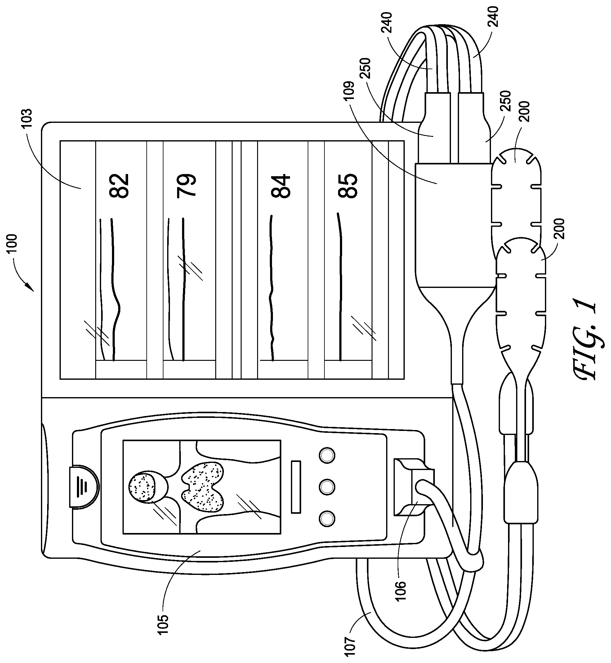
FIG. 1 is a depiction of a patient monitoring system including regional oximetry sensors and a processing and display unit.
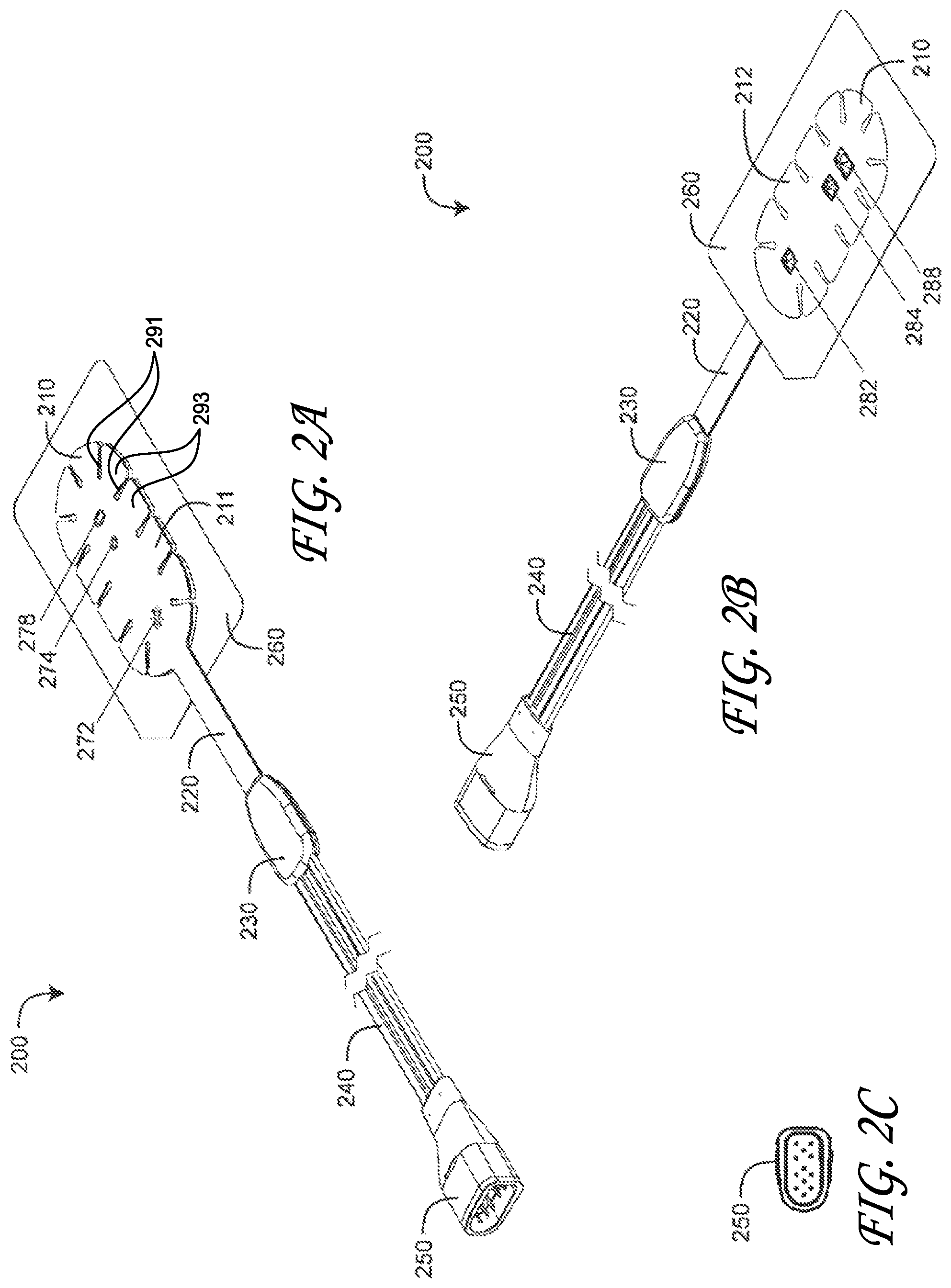
FIGS. 2A-C are top and bottom perspective views and a connector-end view, respectively, of a regional oximetry sensor;
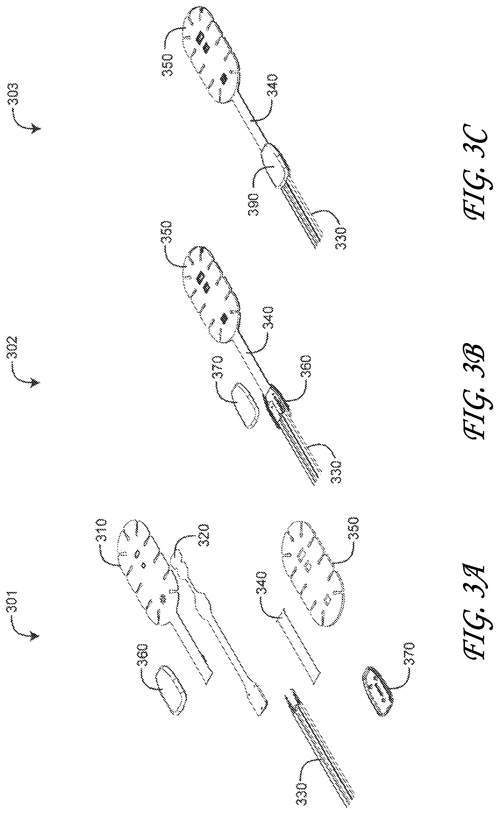
FIGS. 3A-C are top exploded, bottom partially-exploded and bottom assembled perspective views, respectively, of regional oximetry sensor head, stem and shell assemblies;
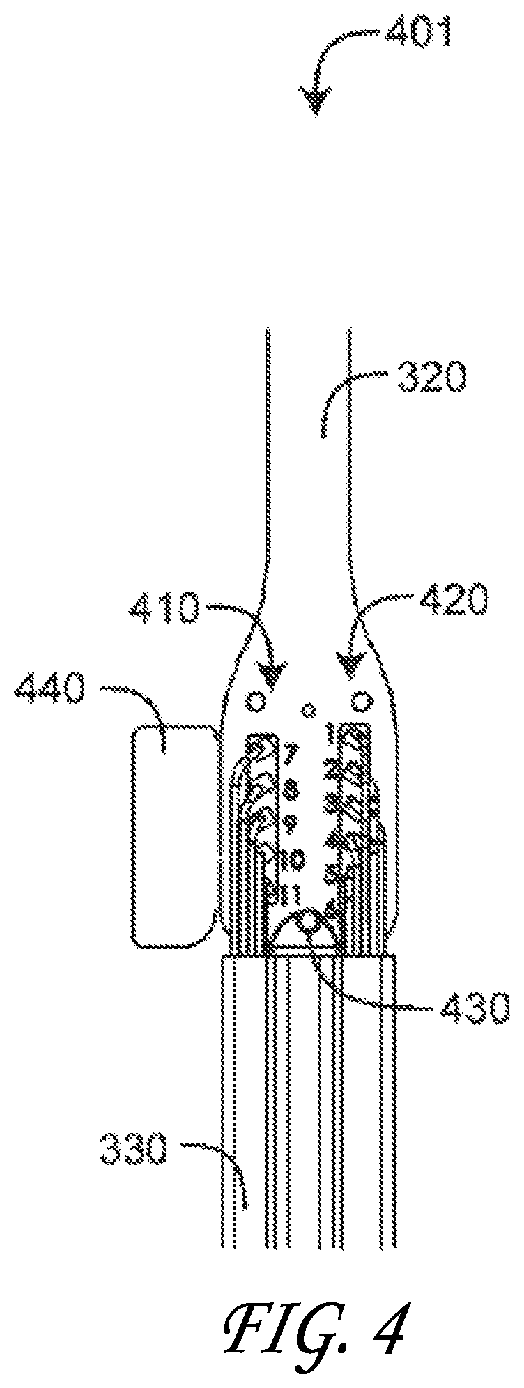
FIG. 4 is a bottom plan view a sensor cable and sensor flex circuit interconnection;
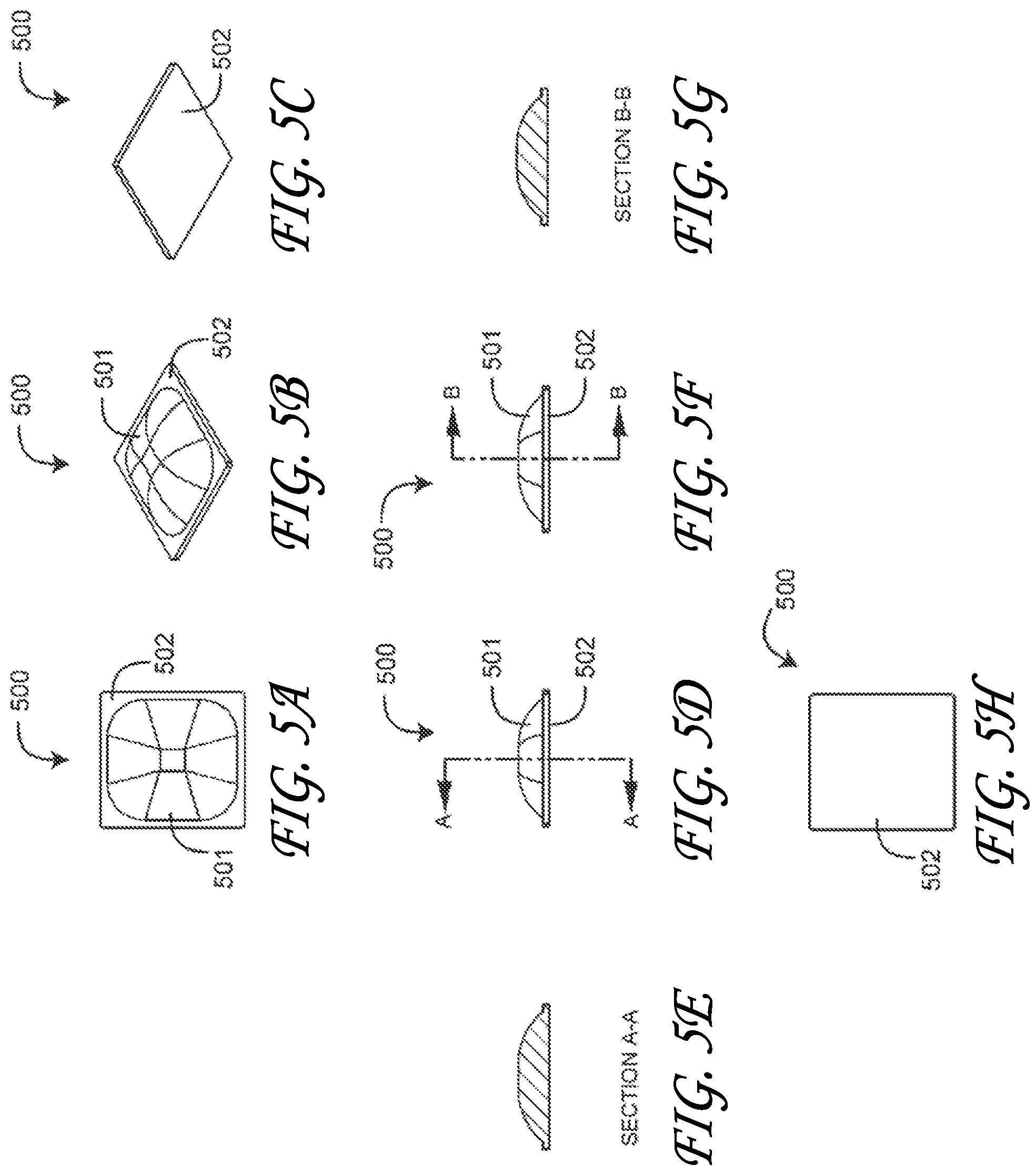
FIGS. 5A-H are a top plan view, top and bottom perspective views, first side and first side cross-sectional views, second side and second side cross-sectional views and a bottom view, respectively, of a near-field detector lens;
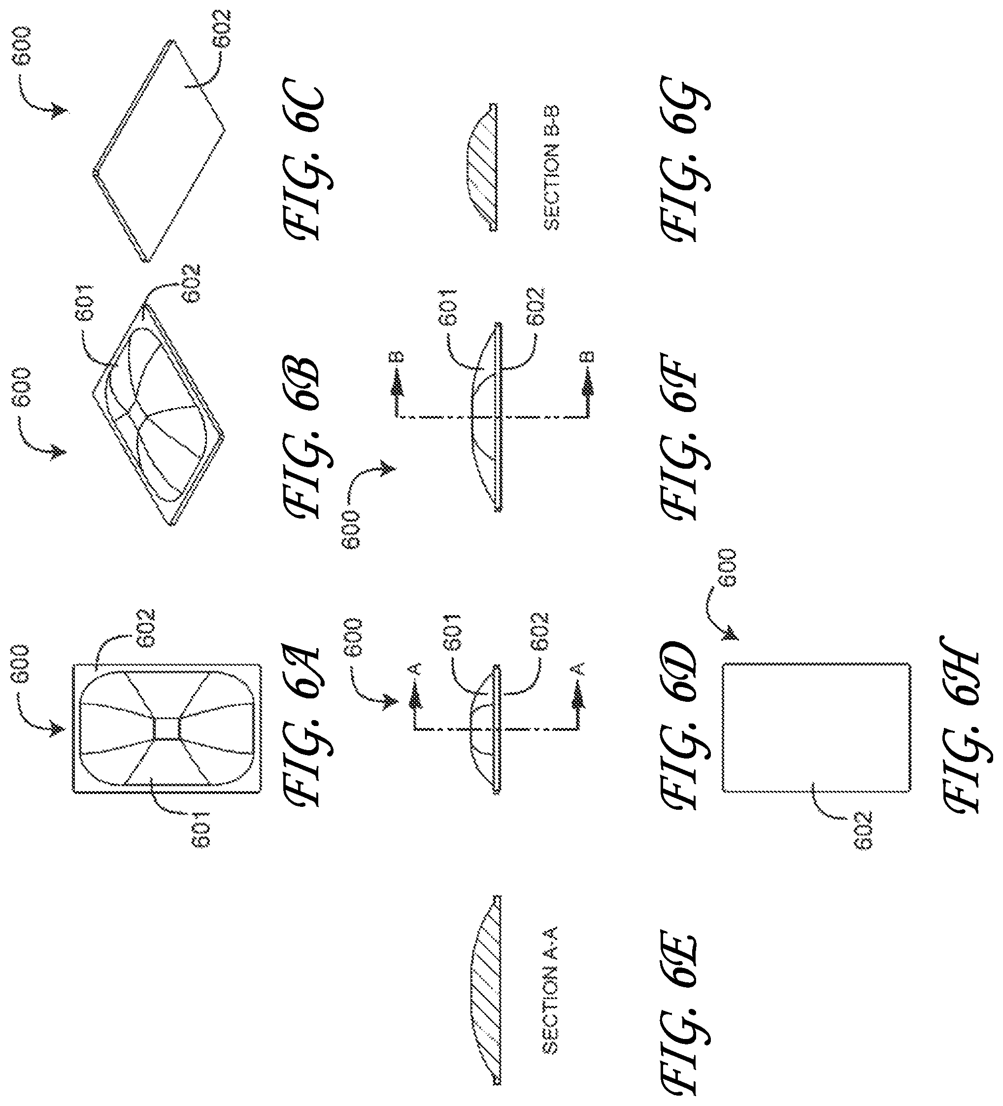
FIGS. 6A-H are a top plan view, top and bottom perspective views, first side and first side cross-sectional views, second side and second side cross-sectional views and a bottom view, respectively, of a far-field detector lens;
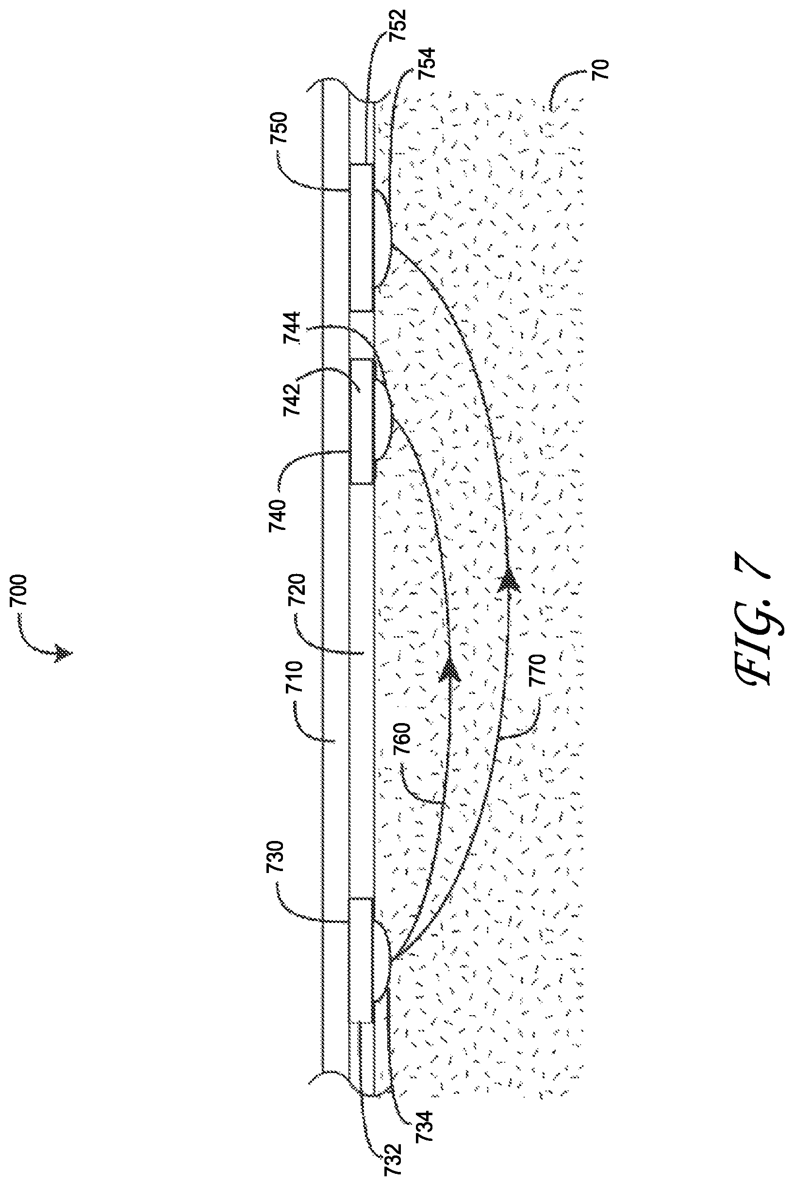
FIG. 7 is a cross-sectional view of a regional oximetry sensor attached to a tissue site and corresponding near-field and far-field emitter-to-detector optical paths;
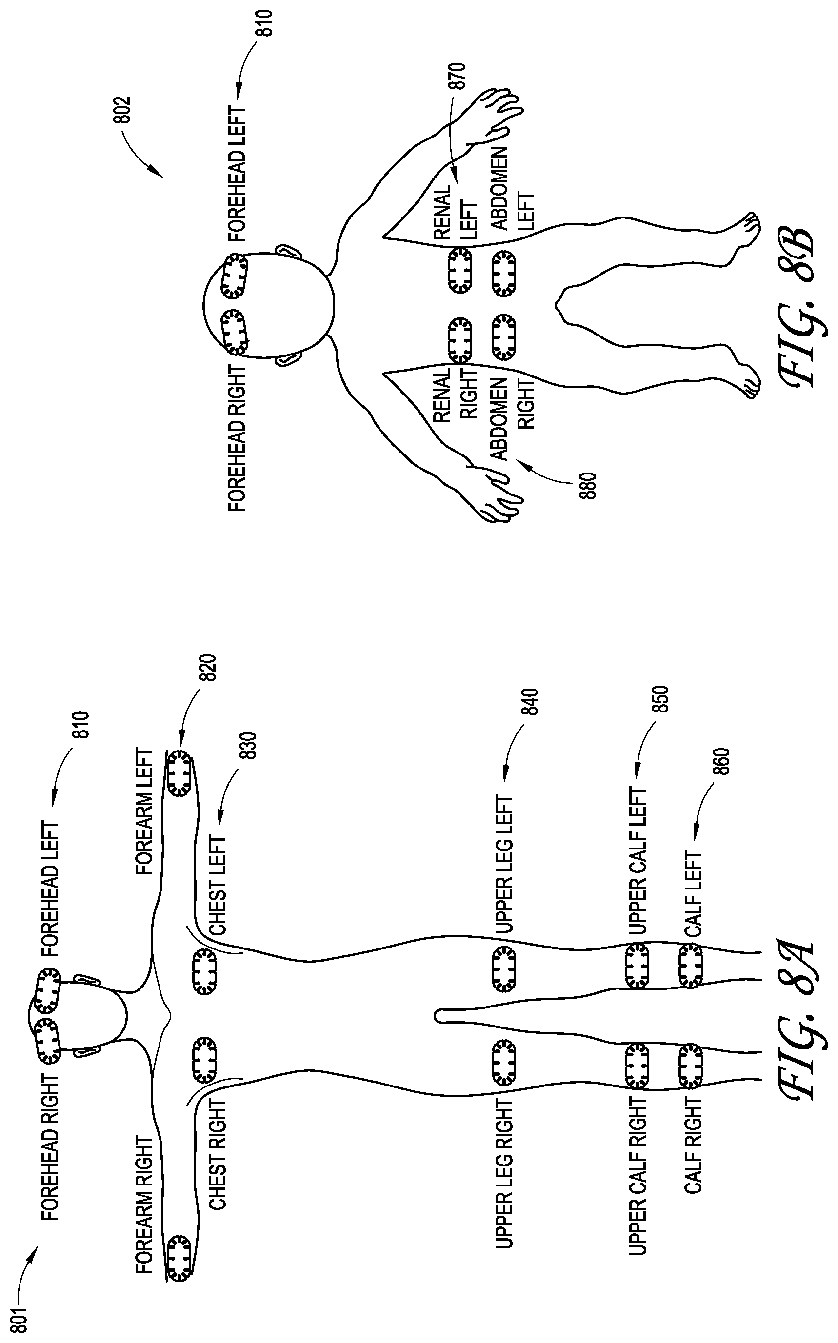
FIGS. 8A-B are a regional oximetry monitor display of sensor placement options for an adult and a child, respectively; and
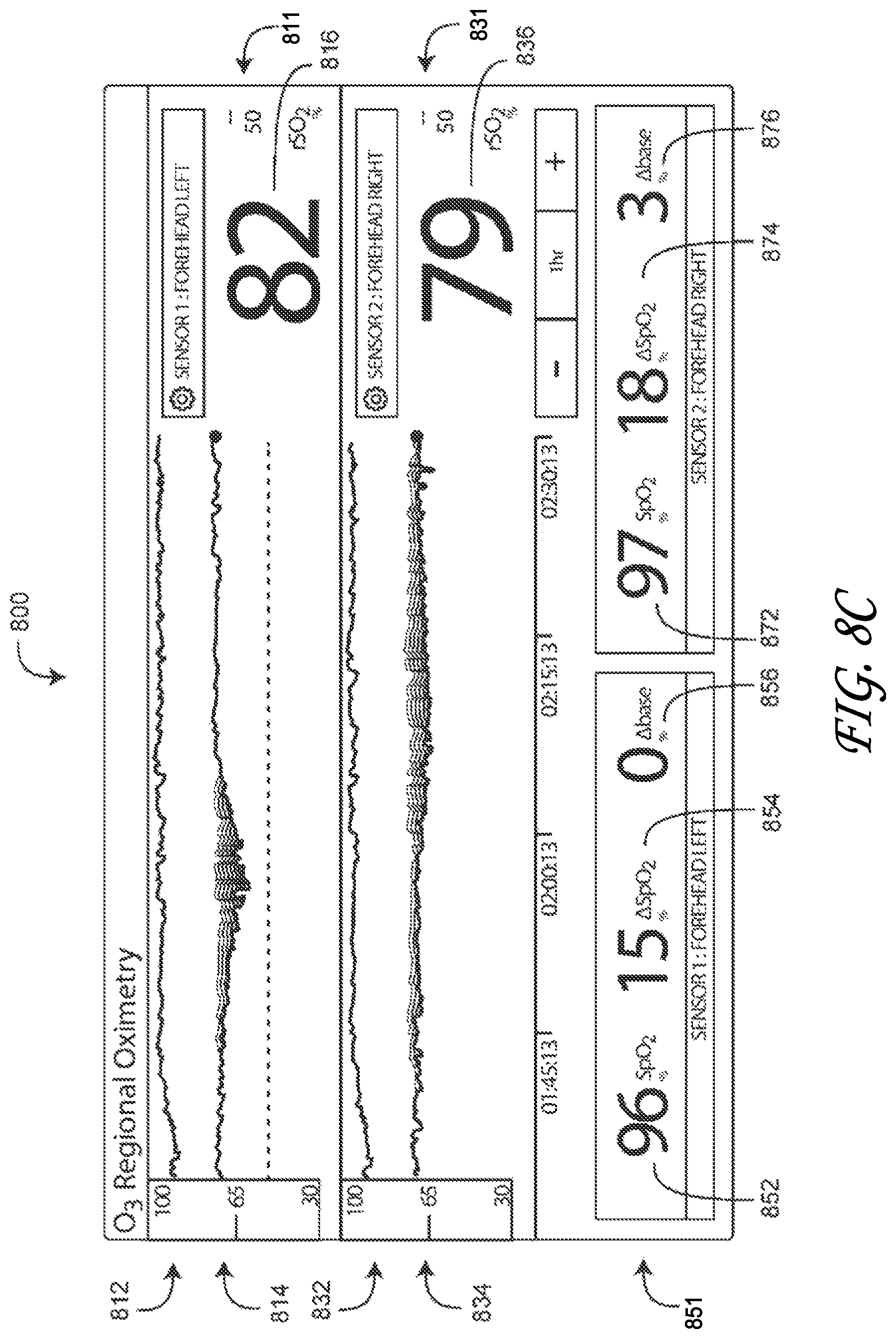
FIG. 8C is an exemplar regional oximetry monitor display using two regional sensors.
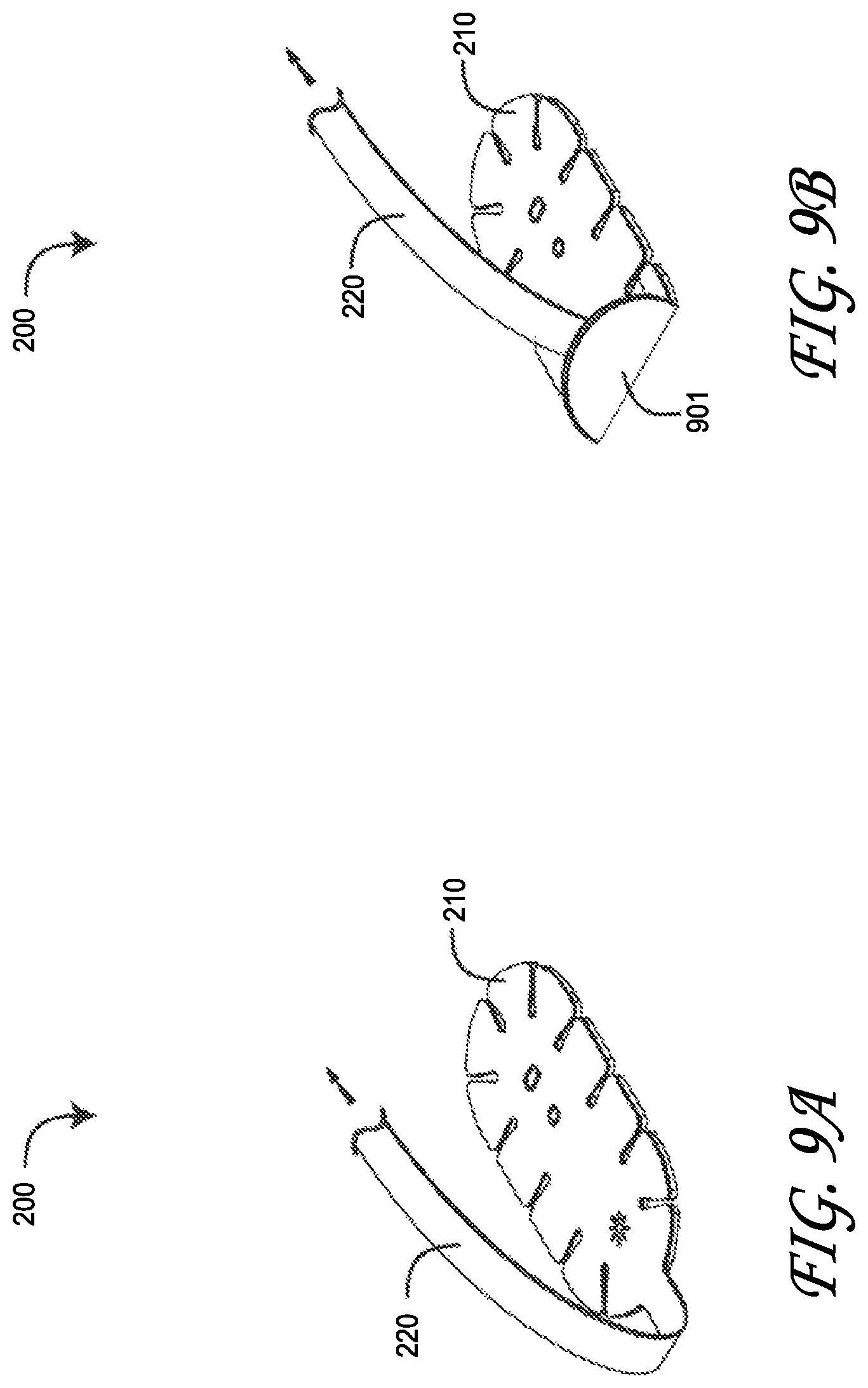
FIGS. 9A-B are top perspective views of a regional oximetry sensor being inadvertently peeled from a skin-surface monitoring-site due to a pulling force applied to the sensor stem and interconnecting sensor cable;
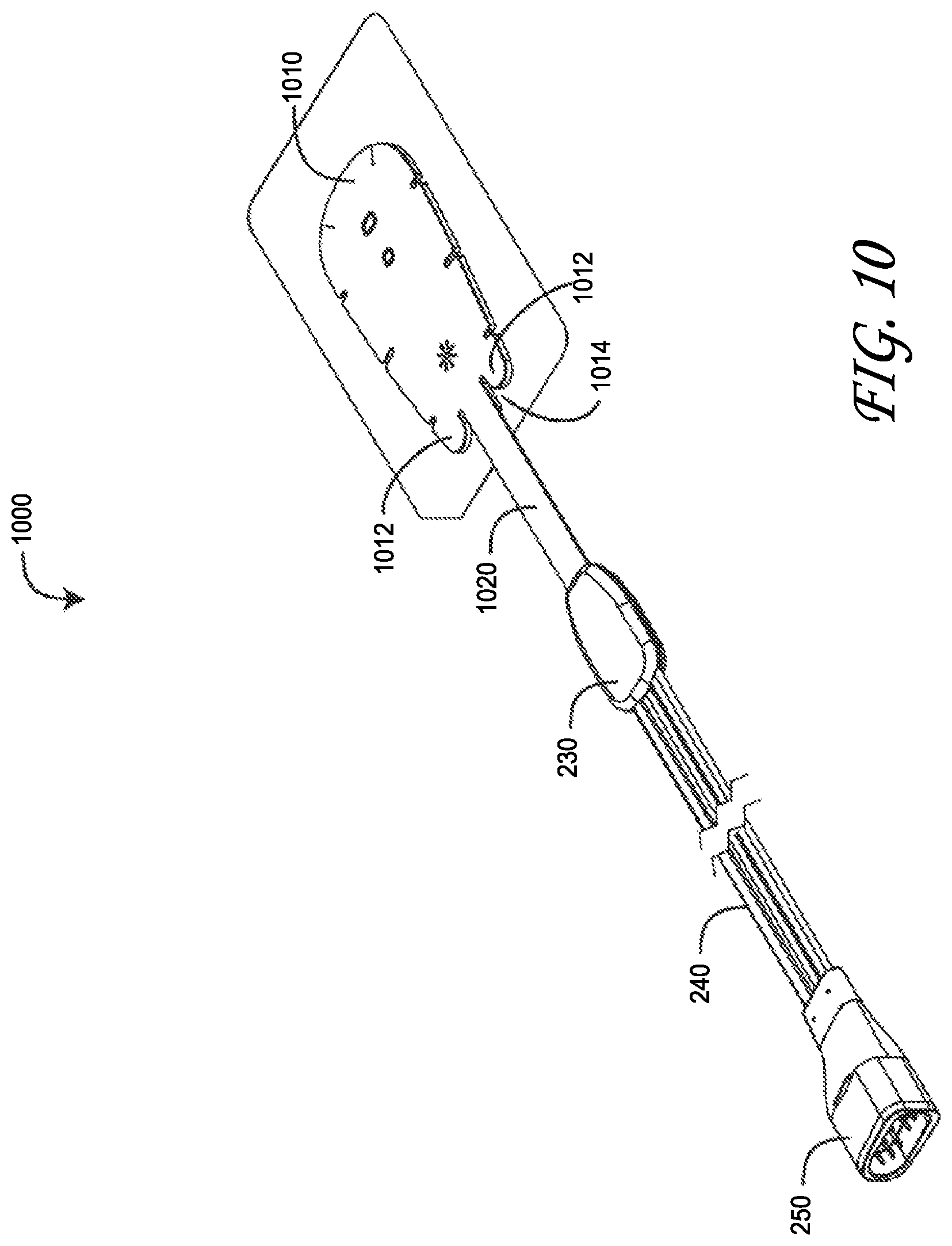
FIG. 10 is a top perspective view of a peel-off resistant regional oximetry sensor;
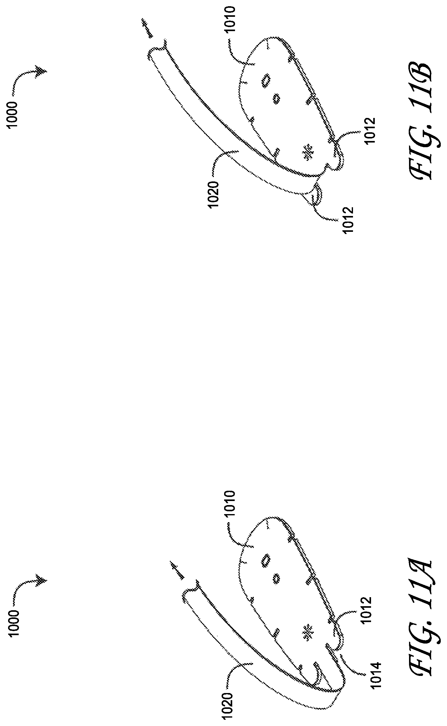
FIGS. 11A-B are top perspective views of a peel-off resistant regional oximetry sensor adhering to a skin-surface monitoring site despite a pulling force applied to the sensor stem and interconnecting sensor cable; and
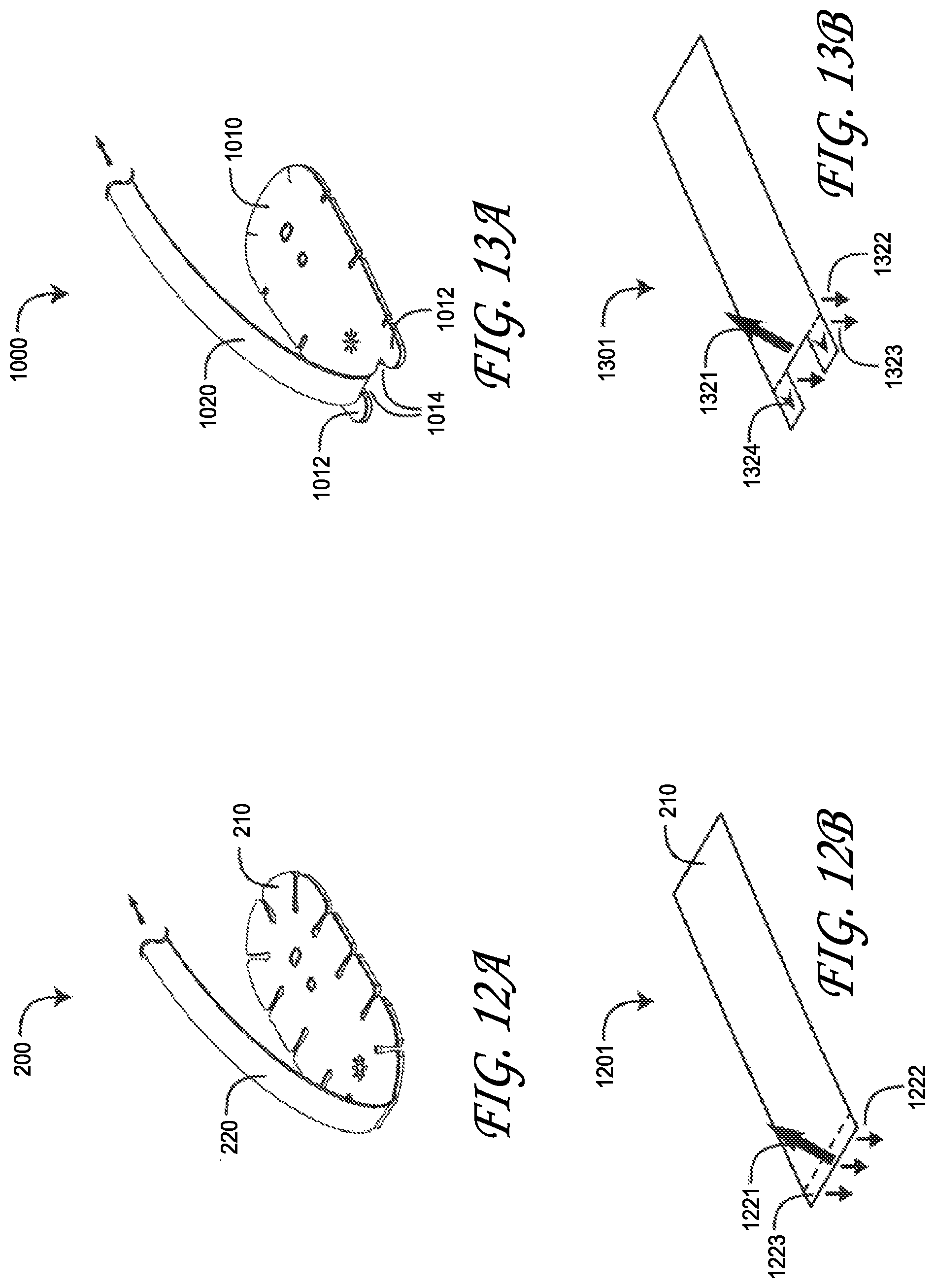
FIGS. 12A, 12B, 13A and 13B are side-by-side, top perspective views of a regional oximetry sensor and a peel-off resistant regional oximetry sensor subjected to like pulling forces and the corresponding impact of anti-peel feet extending from the cable-side of the peel-off resistant regional oximetry sensor.
DETAILED DESCRIPTION
Aspects of the disclosure will now be set forth in detail with respect to the figures and various embodiments. One of skill in the art will appreciate, however, that other embodiments and configurations of the devices and methods disclosed herein will still fall within the scope of this disclosure even if not described in the same detail as some other embodiments. Aspects of various embodiments discussed do not limit the scope of the disclosure herein, which is instead defined by the claims following this description.
FIG. 1 is a physiological monitoring system 100 configured to measure and display regional oximetry measurements. The physiological monitoring system 100 includes at least a display 103 and a processor (not shown) for processing and displaying physiological measurements. The physiological monitoring system 100 also includes at least one sensor 200 for detecting physiological information and providing that physiological information to the processor of the physiological monitoring system 100. In the embodiment of FIG. 1, the physiological monitoring system includes a removable hand held physiological monitor 105. The physiological monitoring system 100 of FIG. 1 also includes a sensor cable system 106 that includes wiring 107 and a sensor connector 109. Sensor connector 109 includes ports for two or more sensors. The sensors are described in more detail with respect to FIGS. 2A-2C.
FIGS. 2A-C illustrate a regional oximetry sensor 200 embodiment having a sensor head 210, stem 220, shell 230, cable 240 and connector 250. The sensor head 210 houses an emitter 282, a near-field detector 284 and a far-field detector 288 within a layered tape having a top side 211 and an adhesive bottom side 212 disposed on a release liner 260. The release liner 260 is removed so as to adhere the bottom side 212 to a skin surface. The sensor head 210 also includes notches or channels 291 that form cutouts 293. The cutouts 293 are independently flexible from other neighboring cutouts. Because of the various placement locations of the sensors on the human body and the movement forces placed on regional oximetry sensors, the cutouts 293 allow the sensor head 210 to be relatively large to increase the measurement area and adhesive surface area without greatly inhibiting patient movement. Thus, for example, when a patient moves their forehead with a sensor 200 adhesively attached, the sensor allows for some movement of the underlying skin so that the patient is more comfortable, yet provide a large enough surface area to provide good measurement and adhesive qualities.
The regional oximetry sensor 200 is substantially flat, allowing the sensor to adhere to the patient without significant bulges. The stem 220 extends out radially outward from the sensor head 210. The stem is positioned to extend from a radial edge in order to provide a clean exit from the body for wiring and cables. The radial placement also provides for streamlined sensor construction and prevents unnecessary bending or wrapping of internal or external wires.
The emitter 282 and detectors 284, 288 have a lens that protrudes from the bottom side 212, advantageously providing a robust optics-skin interface. The top side 211 has emitter/detector indicators 272-278 so as to aid precise sensor placement on a patient site. The shell 230 houses the stem 220 to cable 240 interconnect, described in detail with respect to FIGS. 3A-C, below. The connector 250 is a 12-pin, D-shaped plug.
FIGS. 3A-C illustrate an assembly of a regional oximetry sensor portion including a head assembly (FIG. 3A) and a sensor cable to flex circuit interconnect (FIGS. 3B-C). As shown in FIG. 3A, a sensor head assembly 301 has a face tape 310, a flex circuit 320, a sensor cable 330, a stem tape 340, a base tape 350, a shell top 360 and a shell base 370. The face tape 310 and base tape 350 encase the flex circuit 320 and corresponding emitter and detectors. The shell top and base 360, 370 encase the sensor cable 330 to flex circuit 320 interconnect, described in further detail with respect to FIGS. 4A-B, below. The stem tape 340 encases the flex circuit 320 below the base tape 350.
FIG. 4 illustrates sensor flex circuit 320 to sensor cable 330 interconnection. The flex circuit 320 is positioned on mounting pins in the top shell 360 (FIG. 3B). As shown in FIG. 4, cable 330 wires are soldered to flex circuit pads 410, 420. Cable 330 Kevlar bundles are wrapped around a shell post 430 for strain relief and secured with adhesive. A detector shield flap 440 is folded over detector wires soldered to the detector pads 410 and secured with Kapton tape. The base shell 370 (FIG. 3B) is then glued in place over the top shell 360 (FIG. 3B). In the embodiment of FIG. 4, the connections to the flex circuit 320 include four emitter anode conductors controlling four different wavelength emitters, a common emitter cathode conductor and an emitter shield, two near-field detector conductors, two far-field detector conductors and a detector shield. In an embodiment, the emitter and detector connections are physically separated between different circuit pads, for example, pads 410 and 420. This reduces and/or prevents cross talk and noise between the emitter lines and the detector lines. Of course a person of skill in the art will understand from the present disclosures that different numbers and types of connectors can be used with the presently described connection system.
FIGS. 5A-H illustrate an emitter lens and a near-field detector lens 500 having a generally half-dome focus element 501 and a generally rectangular, planar base 502. As described above, the lens base 502 is disposed over the flex-circuit-mounted emitter and near-field detector in order to focus emitted and detected light. Also as described above, the lens focus element 501 is configured to gently press into a tissue site when applied to the patient in order to maximize optical transmission via the skin surface. The focus elements can also use different three dimensional shapes as well in order to improve optical coupling with the skin and the present disclosure is not limited to the specific embodiments disclosed herein. For example, the lens can be spherical, cubed, rectangular, square, circular oblong or any other shape to increase optical transmission with the skin.
FIGS. 6A-H illustrate a far-field detector lens 600 having a generally oblong, half-dome focus element 601 and a generally oblong, planar base 602. As described above, the lens base 602 is disposed over the flex-circuit-mounted far-field detector so as focus detector received light. Also as described above, the lens focus element 601 gently presses into a tissue site in order to maximize optical transmission via the skin surface. Also, as described above with respect to FIG. 5, the present disclosure is not limited to the specific dimensions and shape described herein which are provided for illustrative purposes. Rather, as discussed above, the present disclosure extends to other shapes and sizes of a focus element that will improve optical coupling. Moreover, the focus element 601 can comprise two or more different focus elements instead of a single larger focus element.
FIG. 7 illustrates a regional oximetry sensor 700 attached to a tissue site 70 so as to generate near-field 760 and far-field 770 emitter-to-detector optical paths through the tissue site 70. The resulting detector signals are processed so as to calculate and display oxygen saturation (SpO.sub.2), delta oxygen saturation (.DELTA.SpO.sub.2) and regional oxygen saturation (rSO.sub.2), as shown in FIG. 8C, below. The regional oximetry sensor 700 has a flex circuit layer 710, a tape layer 720, an emitter 730, a near-field detector 740 and a far-field detector 750. The emitter 730 and detectors 740, 750 are mechanically and electrically connected to the flex circuit 710. The tape layer 720 is disposed over and adheres to the flex circuit 710. Further, the tape layer 720 attaches the sensor 700 to the skin 70 surface.
As shown in FIG. 7, the emitter 730 has a substrate 732 mechanically and electrically connected to the flex circuit 710 and a lens 734 that extends from the tape layer 720. Similarly, each detector 740, 750 has a substrate 742, 752 and each has a lens 744, 754 that extends from the tape layer. In this manner, the lenses 734, 744, 754 press against the skin 70, advantageously increasing the optical transmission and reception of the emitter 730 and detectors 740, 750 through improved optical coupling. The lenses press into the skin and provide a more direct angle of light propagation through the skin between the emitter and detectors.
FIGS. 8A-B illustrate regional oximetry monitor embodiments for designating adult and child sensor placement sites. As shown in FIG. 8A, an adult form 801 is generated on a user interface display. Between one and four sensor sites can be designated on the adult form 801, including left and right forehead 810, forearm 820, chest 830, upper leg 840, upper calf 850 and calf 860 sites. Accordingly, between one and four sensors 200 (FIGS. 2A-C) can be located on these sites. A monitor in communication with these sensors then displays between one and four corresponding regional oximetry graphs and readouts, as described with respect to FIG. 8C, below. As illustrated in FIGS. 8A-8C, the sensor can be positioned on a patient so that the sensor stem 220 and attached cabling can extend radially out from the body on the various regional oximetry sensor sites. This configuration reduces patient discomfort by preventing wiring from crossing or crisscrossing over a patient face, torso or lower body. This configuration also reduces the potential for entanglement of wires from the multiple sensors and associated cabling.
As shown in FIG. 8B, a child form 802 is generated on a user interface display. Between one and four sensor sites can be designated on the child form 802, including left and right forehead 810, left and right renal 870, and left and right abdomen 880 sites. Any number of regional oximetry sensors can be deployed on a patient at the same time, but generally, between one and four sensors 200 (FIGS. 2A-C) are located on these sites at a given time. A monitor in communication with these sensors then displays between a corresponding regional oximetry graphs and readouts for each sensor, as described with respect to FIG. 8C, below. The displays of FIGS. 8A and 8B can also be selectively shown such that, for example, only an upper torso portion of the graphic is shown to prevent confusion by a care provider.
FIG. 8C illustrates a regional oximetry display 800 embodiment for monitoring parameters derived from between one and four regional oximetry sensors 200 (FIGS. 2A-C). This particular example is a two sensor display for monitoring, for example, a forehead left 811 site and a forehead right 831 site. In an upper display portion, the forehead left 812 site displays, for example, an SpO.sub.2 graph 812, an rSO.sub.2 graph 814 and an rSO.sub.2 readout 816. Similarly, the forehead right 831 site displays, for example, an SpO.sub.2 graph 832, an rSO.sub.2 graph 834 and an rSO.sub.2 readout 836.
Also shown in FIG. 8C, in a lower display portion, the forehead left 851 site displays, for example, an SpO.sub.2 readout 852, a .DELTA.SO.sub.2 readout 854 and a .DELTA..sub.base readout 856. Similarly, the forehead right 830 site displays, for example, an SpO.sub.2 readout 872, a .DELTA.SO.sub.2 readout 874 and a .DELTA..sub.base readout 876.
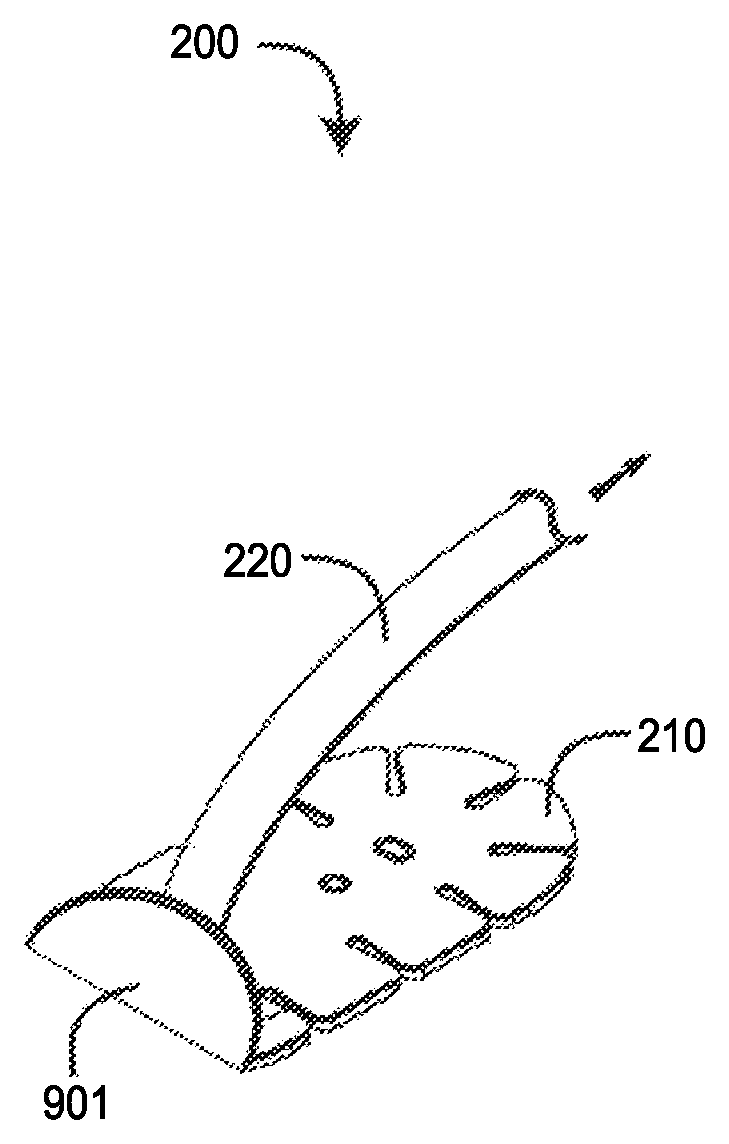
FIGS. 9A-B illustrate a problem that arises with a regional oximetry sensor 200 during use. The connector 250 is fixedly connected to a physiological monitor (not shown) that provides a read-out of parameters derived from the sensor 200. Patient movement away from the monitor may occur in a manner that pulls on the cable (not shown) and bends the attached stem 220 up and/or over the sensor head 210 (FIG. 9A). Continued patient movement away from the monitor may cause a portion of the sensor head 901 to peel off of the patient's skin (FIG. 2B), disrupting accurate parameter measurements. Indeed, continued patient movement may completely dislodge the sensor head 210 from the patient.
A peel-off resistant regional oximetry sensor has a sensor head attachable to a patient skin surface so as to transmit optical radiation into the skin and receive that optical radiation after attenuation by blood flow within the skin. A stem extending from the sensor head transmits electrical signals between the sensor head and an attached cable. The stem is terminated interior to the sensor head and away from a sensor head edge so as to define feet along either side of the stem distal the stem termination. The stem interior termination substantially transforming a peel load on a sensor head adhesive to less challenging tension and shear loads on the sensor head adhesive.
FIG. 10 illustrates an advantageous peel-off resistant regional oximetry sensor 1000 embodiment having a sensor head 1010, stem 1020, shell 230, cable 240 and connector 250. The sensor head 1010 houses an emitter, a near-field detector and a far-field detector within a layered tape having a top side and an adhesive bottom side disposed on a release liner, similar to that described with respect to FIGS. 2A-B, above. The peel-off resistant regional oximetry sensor 1000 has peel-resistant feet 1012 proximately disposed on either side of the stem. The feet are defined by stem slots 1014 separating the feet from the stem. This configuration advantageously moves the stem 1020 base from the edge of the sensor head (e.g. 210 FIG. 2A) to the interior of the sensor head 1010. As a result, potential peel loads on the sensor head adhesive resulting from the stem 1020 being pulled over the sensor head are substantially reduced, as described with respect to FIGS. 12A-13B, below.
FIGS. 11A-B illustrate a peel-off resistant regional oximetry sensor 1000 adhering to a skin-surface monitoring site despite a pulling force applied to the sensor stem 1020 and interconnecting sensor cable. Patient movement relative to connected monitor tends to cause the stem 1020 to peel up the sensor head (see FIG. 2B, above). The sensor head feet 1012, however, advantageously extend away from the point where the stem 1020 begins applying a load to the sensor head adhesive, thus counteracting the peel away force. Further the resulting adhesive loads are different in kind and magnitude than the adhesive loads on the sensor head shown and described with respect to FIG. 2, above. Comparative adhesive loads are described in detail with respect to FIGS. 12A-13B, below.
FIGS. 12A-13B illustrate comparative adhesive loads applied to a regional oximetry sensor 200 and a peel-off resistant regional oximetry sensor 1000 resulting from cable forces applied to the sensor head stems 220 (FIGS. 12A-B), 1020 (FIGS. 13A-B). As shown in FIGS. 12A-B, the stem 220 applies a substantial peel load 1221 to the sensor head 210 adhesive resulting in loads 1222, and the peel load 1221 is distributed over a relatively small area 1223 of the sensor head 210. It is well-known that a peel load 1221 is a substantial challenge to any adhesive, and the milder adhesives used on skin cannot easily overcome this challenge. As such, it is relatively easy for the sensor head 210 to become dislodged or completely detached from the patient.
As shown in FIGS. 13A-B, the stem 1020 of sensor 1000 applies load 1321 to the sensor head 1010 adhesive, resulting in loads 1322, 1323, 1324, which are different than those described with respect to FIGS. 12A-B. In particular, there is a marginal peel load on the adhesive as the result of the adhesive feet 1012 positioned opposite the connection point of the stem 1020 to the sensor head 1010. The sheer load 1324 due to the stem force 1321 is much less challenging to the adhesive feet 1012 compared to a peel load, such as peel load 1222. Likewise, the tension load 1323, 1322 due to the stem force 1321 is less challenging to the adhesive feet 1012, compared to a peel load, and that tension load is distributed on both sides of the stem-to-head connection point. That is, the cumulative effect of positioning the stem 1020 somewhat to the interior of the sensor head 1010 and behind the feet 1021 is a greatly diminished adhesive peel load and much less challenging shear and tension loads distributed over a larger adhesive footprint. The advantageous result is a sensor head-to-cable stem interface that is much less likely to dislodge the sensor head from the patient when forces are applied to the sensor cable. Further, more skin-friendly adhesives can be utilized for sensor head attachment as a result of lowered adhesive loads.
A peel-off resistant regional oximetry sensor has been disclosed in detail in connection with various embodiments. These embodiments are disclosed by way of examples only and are not to limit the scope of this disclosure or the claims that follow. One of ordinary skill in art will appreciate many variations and modifications.
Terminology
Embodiments have been described in connection with the accompanying drawings. However, it should be understood that the figures are not drawn to scale. Distances, angles, etc. are merely illustrative and do not necessarily bear an exact relationship to actual dimensions and layout of the devices illustrated. In addition, the foregoing embodiments have been described at a level of detail to allow one of ordinary skill in the art to make and use the devices, systems, etc. described herein. A wide variety of variation is possible. Components, elements, and/or steps can be altered, added, removed, or rearranged. While certain embodiments have been explicitly described, other embodiments will become apparent to those of ordinary skill in the art based on this disclosure.
Conditional language used herein, such as, among others, "can," "could," "might," "may," "e.g.," and the like, unless specifically stated otherwise, or otherwise understood within the context as used, is generally intended to convey that certain embodiments include, while other embodiments do not include, certain features, elements and/or states. Thus, such conditional language is not generally intended to imply that features, elements and/or states are in any way required for one or more embodiments or that one or more embodiments necessarily include logic for deciding, with or without author input or prompting, whether these features, elements and/or states are included or are to be performed in any particular embodiment.
Depending on the embodiment, certain acts, events, or functions of any of the methods described herein can be performed in a different sequence, can be added, merged, or left out altogether (e.g., not all described acts or events are necessary for the practice of the method). Moreover, in certain embodiments, acts or events can be performed concurrently, e.g., through multi-threaded processing, interrupt processing, or multiple processors or processor cores, rather than sequentially.
The various illustrative logical blocks, engines, modules, circuits, and algorithm steps described in connection with the embodiments disclosed herein can be implemented as electronic hardware, computer software, or combinations of both. To clearly illustrate this interchangeability of hardware and software, various illustrative components, blocks, modules, circuits, and steps have been described above generally in terms of their functionality. Whether such functionality is implemented as hardware or software depends upon the particular application and design constraints imposed on the overall system. The described functionality can be implemented in varying ways for each particular application, but such implementation decisions should not be interpreted as causing a departure from the scope of the disclosure.
The various illustrative logical blocks, modules, and circuits described in connection with the embodiments disclosed herein can be implemented or performed with a general purpose processor, a digital signal processor (DSP), an application specific integrated circuit (ASIC), a field programmable gate array (FPGA) or other programmable logic device, discrete gate or transistor logic, discrete hardware components, or any combination thereof designed to perform the functions described herein. A general purpose processor can be a microprocessor, but in the alternative, the processor can be any conventional processor, controller, microcontroller, or state machine. A processor can also be implemented as a combination of computing devices, e.g., a combination of a DSP and a microprocessor, a plurality of microprocessors, one or more microprocessors in conjunction with a DSP core, or any other such configuration.
The blocks of the methods and algorithms described in connection with the embodiments disclosed herein can be embodied directly in hardware, in a software module executed by a processor, or in a combination of the two. A software module can reside in RAM memory, flash memory, ROM memory, EPROM memory, EEPROM memory, registers, a hard disk, a removable disk, a CD-ROM, or any other form of computer-readable storage medium known in the art. An exemplary storage medium is coupled to a processor such that the processor can read information from, and write information to, the storage medium. In the alternative, the storage medium can be integral to the processor. The processor and the storage medium can reside in an ASIC. The ASIC can reside in a user terminal. In the alternative, the processor and the storage medium can reside as discrete components in a user terminal.
While the above detailed description has shown, described, and pointed out novel features as applied to various embodiments, it will be understood that various omissions, substitutions, and changes in the form and details of the devices or algorithms illustrated can be made without departing from the spirit of the disclosure. As will be recognized, certain embodiments of the inventions described herein can be embodied within a form that does not provide all of the features and benefits set forth herein, as some features can be used or practiced separately from others. The scope of certain inventions disclosed herein is indicated by the appended claims rather than by the foregoing description. All changes which come within the meaning and range of equivalency of the claims are to be embraced within their scope.
* * * * *
D00000
D00001
D00002
D00003
D00004
D00005
D00006
D00007
D00008
D00009
D00010
D00011
D00012
D00013
XML
uspto.report is an independent third-party trademark research tool that is not affiliated, endorsed, or sponsored by the United States Patent and Trademark Office (USPTO) or any other governmental organization. The information provided by uspto.report is based on publicly available data at the time of writing and is intended for informational purposes only.
While we strive to provide accurate and up-to-date information, we do not guarantee the accuracy, completeness, reliability, or suitability of the information displayed on this site. The use of this site is at your own risk. Any reliance you place on such information is therefore strictly at your own risk.
All official trademark data, including owner information, should be verified by visiting the official USPTO website at www.uspto.gov. This site is not intended to replace professional legal advice and should not be used as a substitute for consulting with a legal professional who is knowledgeable about trademark law.