Epicardial anchor devices and methods
Vidlund , et al.
U.S. patent number 10,610,354 [Application Number 15/001,727] was granted by the patent office on 2020-04-07 for epicardial anchor devices and methods. This patent grant is currently assigned to Tendyne Holdings, Inc.. The grantee listed for this patent is Tendyne Holdings, Inc.. Invention is credited to Mark Christianson, Craig Ekvall, Robert M. Vidlund.


View All Diagrams
| United States Patent | 10,610,354 |
| Vidlund , et al. | April 7, 2020 |
Epicardial anchor devices and methods
Abstract
Apparatus and methods are described herein for anchoring a prosthetic heart valve. In some embodiments, an apparatus includes a tether attachment member that includes a base member that defines at least a portion of a tether passageway through which a portion of a tether extending from a prosthetic heart valve can be received therethrough. The base member defines a locking pin channel that intersects the tether passageway. A locking pin is disposable within the locking pin channel and movable between a first position in which the locking pin is at a spaced distance from the tether passageway, and a second position in which the locking pin intersects the tether passageway and can engage the portion of a tether disposed therein to secure the tether to the tether attachment member.
| Inventors: | Vidlund; Robert M. (Forest Lake, MN), Christianson; Mark (Plymouth, MN), Ekvall; Craig (East Bethel, MN) | ||||||||||
|---|---|---|---|---|---|---|---|---|---|---|---|
| Applicant: |
|
||||||||||
| Assignee: | Tendyne Holdings, Inc. (St.
Paul, MN) |
||||||||||
| Family ID: | 55262613 | ||||||||||
| Appl. No.: | 15/001,727 | ||||||||||
| Filed: | January 20, 2016 |
Prior Publication Data
| Document Identifier | Publication Date | |
|---|---|---|
| US 20160143736 A1 | May 26, 2016 | |
Related U.S. Patent Documents
| Application Number | Filing Date | Patent Number | Issue Date | ||
|---|---|---|---|---|---|
| PCT/US2014/049218 | Jul 31, 2014 | ||||
| 14224764 | Mar 25, 2014 | ||||
| 61861356 | Aug 1, 2013 | ||||
| 61895975 | Oct 25, 2013 | ||||
| Current U.S. Class: | 1/1 |
| Current CPC Class: | A61B 17/0401 (20130101); A61B 17/0487 (20130101); A61F 2/2418 (20130101); A61B 17/0057 (20130101); A61B 2017/0453 (20130101); A61F 2/2457 (20130101); A61B 2017/00477 (20130101); A61B 2017/0464 (20130101); A61F 2220/0008 (20130101); A61B 2017/0417 (20130101); A61B 2017/0409 (20130101); A61B 2017/0448 (20130101); A61B 2017/0404 (20130101); A61F 2230/0069 (20130101); A61B 2017/00575 (20130101); A61B 2017/00243 (20130101); A61B 2017/0414 (20130101); A61B 2017/0061 (20130101); A61B 2090/3966 (20160201) |
| Current International Class: | A61B 17/04 (20060101); A61B 17/00 (20060101); A61F 2/24 (20060101); A61B 90/00 (20160101) |
| Field of Search: | ;623/2.11 ;24/132R,134KB,135N ;600/146 |
References Cited [Referenced By]
U.S. Patent Documents
| 2697008 | December 1954 | Rowley |
| 3409013 | November 1968 | Berry |
| 3472230 | October 1969 | Fogarty et al. |
| 3476101 | November 1969 | Ross |
| 3548417 | December 1970 | Kisher |
| 3587115 | June 1971 | Shiley |
| 3657744 | April 1972 | Ersek |
| 3671979 | June 1972 | Moulopoulos |
| 3714671 | February 1973 | Edwards et al. |
| 3755823 | September 1973 | Hancock |
| 3976079 | August 1976 | Samuels et al. |
| 4003382 | January 1977 | Dyke |
| 4035849 | July 1977 | Angell et al. |
| 4056854 | November 1977 | Boretos et al. |
| 4073438 | February 1978 | Meyer |
| 4106129 | August 1978 | Carpentier et al. |
| 4222126 | September 1980 | Boretos et al. |
| 4265694 | May 1981 | Boretos et al. |
| 4297749 | November 1981 | Davis et al. |
| 4339831 | July 1982 | Johnson |
| 4343048 | August 1982 | Ross et al. |
| 4345340 | August 1982 | Rosen |
| 4373216 | February 1983 | Klawitter |
| 4406022 | September 1983 | Roy |
| 4470157 | September 1984 | Love |
| 4490859 | January 1985 | Black et al. |
| 4535483 | August 1985 | Klawitter et al. |
| 4574803 | March 1986 | Storz |
| 4585705 | April 1986 | Broderick et al. |
| 4592340 | June 1986 | Boyles |
| 4605407 | August 1986 | Black et al. |
| 4612011 | September 1986 | Kautzky |
| 4626255 | December 1986 | Reichart et al. |
| 4638886 | January 1987 | Marietta |
| 4643732 | February 1987 | Pietsch et al. |
| 4655771 | April 1987 | Wallsten |
| 4692164 | September 1987 | Dzemeshkevich et al. |
| 4733665 | March 1988 | Palmaz |
| 4759758 | July 1988 | Gabbay |
| 4762128 | September 1988 | Rosenbluth |
| 4777951 | October 1988 | Cribier et al. |
| 4787899 | November 1988 | Lazarus |
| 4787901 | November 1988 | Baykut |
| 4796629 | January 1989 | Grayzel |
| 4824180 | April 1989 | Levrai |
| 4829990 | May 1989 | Thuroff et al. |
| 4830117 | May 1989 | Capasso |
| 4851001 | July 1989 | Taheri |
| 4856516 | August 1989 | Hillstead |
| 4858810 | August 1989 | Intlekofer |
| 4878495 | November 1989 | Grayzel |
| 4878906 | November 1989 | Lindemann et al. |
| 4883458 | November 1989 | Shiber |
| 4922905 | May 1990 | Strecker |
| 4923013 | May 1990 | De Gennaro |
| 4960424 | October 1990 | Grooters |
| 4966604 | October 1990 | Reiss |
| 4979939 | December 1990 | Shiber |
| 4986830 | January 1991 | Owens et al. |
| 4994077 | February 1991 | Dobben |
| 4996873 | March 1991 | Takeuchi |
| 5007896 | April 1991 | Shiber |
| 5026366 | June 1991 | Leckrone |
| 5032128 | July 1991 | Alonso |
| 5035706 | July 1991 | Giantureo et al. |
| 5037434 | August 1991 | Lane |
| 5047041 | September 1991 | Sammuels |
| 5059177 | October 1991 | Towne et al. |
| 5064435 | November 1991 | Porter |
| 5080668 | January 1992 | Bolz et al. |
| 5085635 | February 1992 | Cragg |
| 5089015 | February 1992 | Ross |
| 5152771 | October 1992 | Sabbaghian et al. |
| 5163953 | November 1992 | Vince |
| 5167628 | December 1992 | Boyles |
| 5192297 | March 1993 | Hull |
| 5201880 | April 1993 | Wright et al. |
| 5266073 | November 1993 | Wall |
| 5282847 | February 1994 | Trescony et al. |
| 5295958 | March 1994 | Shturman |
| 5306296 | April 1994 | Wright et al. |
| 5332402 | July 1994 | Teitelbaum |
| 5336616 | August 1994 | Livesey et al. |
| 5344442 | September 1994 | Deac |
| 5360444 | November 1994 | Kusuhara |
| 5364407 | November 1994 | Poll |
| 5370685 | December 1994 | Stevens |
| 5397351 | March 1995 | Pavcnik et al. |
| 5411055 | May 1995 | Kane et al. |
| 5411552 | May 1995 | Andersen et al. |
| 5415667 | May 1995 | Frater |
| 5443446 | August 1995 | Shturman |
| 5480424 | January 1996 | Cox |
| 5500014 | March 1996 | Quijano et al. |
| 5545209 | August 1996 | Roberts et al. |
| 5545214 | August 1996 | Stevens |
| 5549665 | August 1996 | Vesely et al. |
| 5554184 | September 1996 | Machiraju |
| 5554185 | September 1996 | Block et al. |
| 5571175 | November 1996 | Vanney et al. |
| 5578076 | November 1996 | Krueger |
| 5591185 | January 1997 | Kilmer et al. |
| 5607462 | March 1997 | Imran |
| 5607464 | March 1997 | Trescony et al. |
| 5609626 | March 1997 | Quijano et al. |
| 5639274 | June 1997 | Fischell et al. |
| 5662704 | September 1997 | Gross |
| 5665115 | September 1997 | Cragg |
| 5674279 | October 1997 | Wright et al. |
| 5697905 | December 1997 | Ambrosio |
| 5702368 | December 1997 | Stevens et al. |
| 5716417 | February 1998 | Girard et al. |
| 5728068 | March 1998 | Leone et al. |
| 5728151 | March 1998 | Garrison et al. |
| 5735842 | April 1998 | Krueger et al. |
| 5741333 | April 1998 | Frid |
| 5749890 | May 1998 | Shaknovich |
| 5756476 | May 1998 | Epstein |
| 5769812 | June 1998 | Stevens et al. |
| 5792179 | August 1998 | Sideris |
| 5800508 | September 1998 | Goicoechea et al. |
| 5833673 | November 1998 | Ockuly et al. |
| 5840081 | November 1998 | Andersen et al. |
| 5855597 | January 1999 | Jayaraman |
| 5855601 | January 1999 | Bessler |
| 5855602 | January 1999 | Angell |
| 5904697 | May 1999 | Gifford, III et al. |
| 5925063 | July 1999 | Khosravi |
| 5957949 | September 1999 | Leonhardt et al. |
| 5968052 | October 1999 | Sullivan, III et al. |
| 5968068 | October 1999 | Dehdashtian et al. |
| 5972030 | October 1999 | Garrison et al. |
| 5993481 | November 1999 | Marcade et al. |
| 6027525 | February 2000 | Suh et al. |
| 6042607 | March 2000 | Williamson, IV et al. |
| 6045497 | April 2000 | Schweich, Jr. et al. |
| 6063112 | May 2000 | Sgro et al. |
| 6077214 | June 2000 | Mortier et al. |
| 6099508 | August 2000 | Bousquet |
| 6132473 | October 2000 | Williams et al. |
| 6168614 | January 2001 | Andersen et al. |
| 6171335 | January 2001 | Wheatley et al. |
| 6174327 | January 2001 | Mertens et al. |
| 6183411 | February 2001 | Mortier et al. |
| 6210408 | April 2001 | Chandrasakaran et al. |
| 6217585 | April 2001 | Houser et al. |
| 6221091 | April 2001 | Khosravi |
| 6231602 | May 2001 | Carpentier et al. |
| 6245102 | June 2001 | Jayaraman |
| 6260552 | July 2001 | Mortier et al. |
| 6261222 | July 2001 | Schweich, Jr. et al. |
| 6264602 | July 2001 | Mortier et al. |
| 6287339 | September 2001 | Vazquez et al. |
| 6299637 | October 2001 | Shaolian |
| 6302906 | October 2001 | Goecoechea et al. |
| 6312465 | November 2001 | Griffin et al. |
| 6332893 | December 2001 | Mortier et al. |
| 6350277 | February 2002 | Kocur |
| 6358277 | March 2002 | Duran |
| 6379372 | April 2002 | Dehdashtian et al. |
| 6402679 | June 2002 | Mortier et al. |
| 6402680 | June 2002 | Mortier et al. |
| 6402781 | June 2002 | Langberg et al. |
| 6406420 | June 2002 | McCarthy et al. |
| 6425916 | July 2002 | Garrison et al. |
| 6440164 | August 2002 | Di Matteo et al. |
| 6454799 | September 2002 | Schreck |
| 6458153 | October 2002 | Bailey et al. |
| 6461382 | October 2002 | Cao |
| 6468660 | October 2002 | Ogle et al. |
| 6482228 | November 2002 | Norred |
| 6488704 | December 2002 | Connelly et al. |
| 6537198 | March 2003 | Vidlund et al. |
| 6540782 | April 2003 | Snyders |
| 6569196 | May 2003 | Vesely et al. |
| 6575252 | June 2003 | Reed |
| 6582462 | June 2003 | Andersen et al. |
| 6605112 | August 2003 | Moll |
| 6616684 | September 2003 | Vidlund et al. |
| 6622730 | September 2003 | Ekvall et al. |
| 6629534 | October 2003 | St. Goar et al. |
| 6629921 | October 2003 | Schweich, Jr. et al. |
| 6648077 | November 2003 | Hoffman |
| 6648921 | November 2003 | Anderson et al. |
| 6652578 | November 2003 | Bailey et al. |
| 6669724 | December 2003 | Park et al. |
| 6706065 | March 2004 | Langberg et al. |
| 6709456 | March 2004 | Langberg et al. |
| 6723038 | April 2004 | Schroeder et al. |
| 6726715 | April 2004 | Sutherland |
| 6730118 | May 2004 | Spenser et al. |
| 6733525 | May 2004 | Yang et al. |
| 6740105 | May 2004 | Yodfat et al. |
| 6746401 | June 2004 | Panescu |
| 6746471 | June 2004 | Mortier et al. |
| 6752813 | June 2004 | Goldfarb et al. |
| 6764510 | July 2004 | Vidlund et al. |
| 6797002 | September 2004 | Spence et al. |
| 6810882 | November 2004 | Langberg et al. |
| 6830584 | December 2004 | Seguin |
| 6854668 | February 2005 | Wancho et al. |
| 6855144 | February 2005 | Lesh |
| 6858001 | February 2005 | Aboul-Hosn |
| 6890353 | May 2005 | Cohn et al. |
| 6893460 | May 2005 | Spenser et al. |
| 6896690 | May 2005 | Lambrecht et al. |
| 6908424 | June 2005 | Mortier et al. |
| 6908481 | June 2005 | Cribier |
| 6936067 | August 2005 | Buchanan |
| 6945996 | September 2005 | Sedransk |
| 6955175 | October 2005 | Stevens et al. |
| 6974476 | December 2005 | McGuckin et al. |
| 6976543 | December 2005 | Fischer |
| 6997950 | February 2006 | Chawia |
| 7018406 | March 2006 | Seguin et al. |
| 7018408 | March 2006 | Bailey et al. |
| 7044905 | May 2006 | Vidlund et al. |
| 7060021 | June 2006 | Wilk |
| 7077862 | July 2006 | Vidlund et al. |
| 7087064 | August 2006 | Hyde |
| 7100614 | September 2006 | Stevens et al. |
| 7101395 | September 2006 | Tremulis et al. |
| 7108717 | September 2006 | Freidberg |
| 7112219 | September 2006 | Vidlund et al. |
| 7115141 | October 2006 | Menz et al. |
| 7141064 | November 2006 | Scott et al. |
| 7175656 | February 2007 | Khairkhahan |
| 7198646 | April 2007 | Figulla et al. |
| 7201772 | April 2007 | Schwammenthal et al. |
| 7247134 | July 2007 | Vidlund et al. |
| 7252682 | August 2007 | Seguin |
| 7267686 | September 2007 | DiMatteo et al. |
| 7275604 | October 2007 | Wall |
| 7276078 | October 2007 | Spenser et al. |
| 7276084 | October 2007 | Yang et al. |
| 7316706 | January 2008 | Bloom et al. |
| 7318278 | January 2008 | Zhang et al. |
| 7326236 | February 2008 | Andreas et al. |
| 7329278 | February 2008 | Seguin et al. |
| 7331991 | February 2008 | Kheradvar et al. |
| 7335213 | February 2008 | Hyde et al. |
| 7374571 | May 2008 | Pease et al. |
| 7377941 | May 2008 | Rhee et al. |
| 7381210 | June 2008 | Zarbatany et al. |
| 7381218 | June 2008 | Schreck |
| 7393360 | July 2008 | Spenser et al. |
| 7404824 | July 2008 | Webler et al. |
| 7416554 | August 2008 | Lam et al. |
| 7422072 | September 2008 | Dade |
| 7429269 | September 2008 | Schwammenthal et al. |
| 7442204 | October 2008 | Schwammenthal et al. |
| 7445631 | November 2008 | Salahieh et al. |
| 7462191 | December 2008 | Spenser et al. |
| 7470285 | December 2008 | Nugent et al. |
| 7500989 | March 2009 | Solem et al. |
| 7503931 | March 2009 | Kowalsky et al. |
| 7510572 | March 2009 | Gabbay |
| 7510575 | March 2009 | Spenser et al. |
| 7513908 | April 2009 | Lattouf |
| 7524330 | April 2009 | Berreklouw |
| 7527647 | May 2009 | Spence |
| 7534260 | May 2009 | Lattouf |
| 7556646 | July 2009 | Yang et al. |
| 7579381 | August 2009 | Dove |
| 7585321 | September 2009 | Cribier |
| 7591847 | September 2009 | Navia et al. |
| 7618446 | November 2009 | Andersen et al. |
| 7618447 | November 2009 | Case et al. |
| 7621948 | November 2009 | Herrmann et al. |
| 7632304 | December 2009 | Park |
| 7632308 | December 2009 | Loulmet |
| 7635386 | December 2009 | Gammie |
| 7674222 | March 2010 | Nikolic et al. |
| 7674286 | March 2010 | Alfieri et al. |
| 7695510 | April 2010 | Bloom et al. |
| 7708775 | May 2010 | Rowe et al. |
| 7748389 | July 2010 | Salahieh et al. |
| 7766961 | August 2010 | Patel et al. |
| 7789909 | September 2010 | Andersen et al. |
| 7803168 | September 2010 | Gifford et al. |
| 7803184 | September 2010 | McGuckin, Jr. et al. |
| 7803185 | September 2010 | Gabbay |
| 7806928 | October 2010 | Rowe et al. |
| 7837727 | November 2010 | Goetz et al. |
| 7854762 | December 2010 | Speziali et al. |
| 7892281 | February 2011 | Seguin et al. |
| 7896915 | March 2011 | Guyenot et al. |
| 7901454 | March 2011 | Kapadia et al. |
| 7927370 | April 2011 | Webler et al. |
| 7931630 | April 2011 | Nishtala et al. |
| 7942928 | May 2011 | Webler et al. |
| 7955247 | June 2011 | Levine et al. |
| 7955385 | June 2011 | Crittenden |
| 7972378 | July 2011 | Tabor et al. |
| 7988727 | August 2011 | Santamore et al. |
| 7993394 | August 2011 | Hariton et al. |
| 8007992 | August 2011 | Tian et al. |
| 8029556 | October 2011 | Rowe |
| 8043368 | October 2011 | Crabtree |
| 8052749 | November 2011 | Salahieh |
| 8052750 | November 2011 | Tuval et al. |
| 8052751 | November 2011 | Aklog et al. |
| 8062355 | November 2011 | Figulla et al. |
| 8062359 | November 2011 | Marquez et al. |
| 8070802 | December 2011 | Lamphere et al. |
| 8109996 | February 2012 | Stacchino et al. |
| 8142495 | March 2012 | Hasenkam et al. |
| 8152821 | April 2012 | Gambale et al. |
| 8157810 | April 2012 | Case et al. |
| 8167932 | May 2012 | Bourang et al. |
| 8167934 | May 2012 | Styrc et al. |
| 8187299 | May 2012 | Goldfarb et al. |
| 8206439 | June 2012 | Gomez Duran |
| 8216301 | July 2012 | Bonhoeffer et al. |
| 8226711 | July 2012 | Mortier et al. |
| 8236045 | August 2012 | Benichou et al. |
| 8241274 | August 2012 | Keogh et al. |
| 8252051 | August 2012 | Chau et al. |
| 8303653 | November 2012 | Bonhoeffer et al. |
| 8308796 | November 2012 | Lashinski et al. |
| 8323334 | December 2012 | Deem et al. |
| 8353955 | January 2013 | Styrc et al. |
| RE44075 | March 2013 | Williamson et al. |
| 8449599 | May 2013 | Chau et al. |
| 8454656 | June 2013 | Tuval |
| 8470028 | June 2013 | Thornton et al. |
| 8480730 | July 2013 | Maurer et al. |
| 8486138 | July 2013 | Vesely |
| 8506623 | August 2013 | Wilson et al. |
| 8506624 | August 2013 | Vidlund et al. |
| 8578705 | November 2013 | Sindano et al. |
| 8579913 | November 2013 | Nielsen |
| 8591573 | November 2013 | Barone |
| 8591576 | November 2013 | Hasenkam et al. |
| 8597347 | December 2013 | Maurer et al. |
| 8685086 | April 2014 | Navia et al. |
| 8790394 | July 2014 | Miller et al. |
| 8845717 | September 2014 | Khairkhahan et al. |
| 8888843 | November 2014 | Khairkhahan et al. |
| 8900214 | December 2014 | Nance et al. |
| 8900295 | December 2014 | Migliazza et al. |
| 8926696 | January 2015 | Cabiri et al. |
| 8932342 | January 2015 | McHugo et al. |
| 8932348 | January 2015 | Solem et al. |
| 8945208 | February 2015 | Jimenez et al. |
| 8956407 | February 2015 | Macoviak et al. |
| 8979922 | March 2015 | Thambar et al. |
| 8986376 | March 2015 | Solem |
| 9011522 | April 2015 | Annest et al. |
| 9023099 | May 2015 | Duffy et al. |
| 9034032 | May 2015 | McLean et al. |
| 9034033 | May 2015 | McLean et al. |
| 9039757 | May 2015 | McLean et al. |
| 9039759 | May 2015 | Alkhatib et al. |
| 9078645 | July 2015 | Conklin |
| 9078749 | July 2015 | Lutter et al. |
| 9084676 | July 2015 | Chau et al. |
| 9095433 | August 2015 | Lutter et al. |
| 9125742 | September 2015 | Yoganathan et al. |
| 9149357 | October 2015 | Sequin |
| 9161837 | October 2015 | Kapadia |
| 9168137 | October 2015 | Subramanian et al. |
| 9232995 | January 2016 | Kovalsky et al. |
| 9232998 | January 2016 | Wilson et al. |
| 9232999 | January 2016 | Maurer et al. |
| 9241702 | January 2016 | Maisano et al. |
| 9254192 | February 2016 | Lutter et al. |
| 9265608 | February 2016 | Miller et al. |
| 9289295 | March 2016 | Aklog et al. |
| 9289297 | March 2016 | Wilson et al. |
| 9345573 | May 2016 | Nyuli et al. |
| 9480557 | November 2016 | Pellegrini et al. |
| 9480559 | November 2016 | Vidlund et al. |
| 9526611 | December 2016 | Tegels et al. |
| 9597181 | March 2017 | Christianson et al. |
| 9610159 | April 2017 | Christianson et al. |
| 9625003 | April 2017 | Hooti |
| 9675454 | June 2017 | Vidlund et al. |
| 9730792 | August 2017 | Lutter et al. |
| 9827092 | November 2017 | Vidlund et al. |
| 9833315 | December 2017 | Vidlund et al. |
| 9867700 | January 2018 | Bakis et al. |
| 9883941 | February 2018 | Hastings et al. |
| 9895221 | February 2018 | Vidlund |
| 9986993 | June 2018 | Vidlund et al. |
| 2001/0018611 | August 2001 | Solem et al. |
| 2001/0021872 | September 2001 | Bailey et al. |
| 2001/0025171 | September 2001 | Mortier et al. |
| 2002/0010427 | January 2002 | Scarfone et al. |
| 2002/0116054 | August 2002 | Lundell et al. |
| 2002/0139056 | October 2002 | Finnell |
| 2002/0151961 | October 2002 | Lashinski et al. |
| 2002/0161377 | October 2002 | Rabkin |
| 2002/0173842 | November 2002 | Buchanan |
| 2002/0183827 | December 2002 | Derus et al. |
| 2003/0010509 | January 2003 | Hoffman |
| 2003/0036698 | February 2003 | Kohler et al. |
| 2003/0050694 | March 2003 | Yang et al. |
| 2003/0078652 | April 2003 | Sutherland |
| 2003/0100939 | May 2003 | Yodfat et al. |
| 2003/0105519 | June 2003 | Fasol et al. |
| 2003/0105520 | June 2003 | Alferness et al. |
| 2003/0120340 | June 2003 | Liska et al. |
| 2003/0130731 | July 2003 | Vidlund et al. |
| 2003/0149476 | August 2003 | Damm et al. |
| 2003/0212454 | November 2003 | Scott et al. |
| 2004/0039436 | February 2004 | Spenser et al. |
| 2004/0049266 | March 2004 | Anduiza et al. |
| 2004/0064014 | April 2004 | Melvin et al. |
| 2004/0092858 | May 2004 | Wilson et al. |
| 2004/0093075 | May 2004 | Kuehne |
| 2004/0097865 | May 2004 | Anderson et al. |
| 2004/0127983 | July 2004 | Mortier et al. |
| 2004/0133263 | July 2004 | Dusbabek et al. |
| 2004/0147958 | July 2004 | Lam et al. |
| 2004/0152947 | August 2004 | Schroeder et al. |
| 2004/0162610 | August 2004 | Liska et al. |
| 2004/0163828 | August 2004 | Silverstein et al. |
| 2004/0181239 | September 2004 | Dorn et al. |
| 2004/0186565 | September 2004 | Schreck |
| 2004/0186566 | September 2004 | Hindrichs et al. |
| 2004/0260317 | December 2004 | Bloom et al. |
| 2004/0260389 | December 2004 | Case et al. |
| 2005/0004652 | January 2005 | Van der Burg et al. |
| 2005/0004666 | January 2005 | Alfieri et al. |
| 2005/0075727 | April 2005 | Wheatley |
| 2005/0080402 | April 2005 | Santamore et al. |
| 2005/0085900 | April 2005 | Case et al. |
| 2005/0096498 | May 2005 | Houser et al. |
| 2005/0107661 | May 2005 | Lau et al. |
| 2005/0113798 | May 2005 | Slater et al. |
| 2005/0113810 | May 2005 | Houser et al. |
| 2005/0113811 | May 2005 | Houser et al. |
| 2005/0119519 | June 2005 | Girard et al. |
| 2005/0121206 | June 2005 | Dolan |
| 2005/0125012 | June 2005 | Houser et al. |
| 2005/0137686 | June 2005 | Salahieh et al. |
| 2005/0137688 | June 2005 | Salahieh et al. |
| 2005/0137695 | June 2005 | Salahieh et al. |
| 2005/0137698 | June 2005 | Salahieh et al. |
| 2005/0148815 | July 2005 | Mortier et al. |
| 2005/0177180 | August 2005 | Kaganov et al. |
| 2005/0197695 | September 2005 | Stacchino |
| 2005/0203614 | September 2005 | Forster et al. |
| 2005/0203615 | September 2005 | Forster et al. |
| 2005/0203617 | September 2005 | Forster et al. |
| 2005/0234546 | October 2005 | Nugent et al. |
| 2005/0240200 | October 2005 | Bergheim |
| 2005/0251209 | November 2005 | Saadat et al. |
| 2005/0256567 | November 2005 | Lim et al. |
| 2005/0283231 | December 2005 | Haug et al. |
| 2005/0288766 | December 2005 | Plain et al. |
| 2006/0004442 | January 2006 | Spenser et al. |
| 2006/0025784 | February 2006 | Starksen et al. |
| 2006/0025857 | February 2006 | Bergheim et al. |
| 2006/0030885 | February 2006 | Hyde |
| 2006/0042803 | March 2006 | Gallaher |
| 2006/0047338 | March 2006 | Jenson et al. |
| 2006/0052868 | March 2006 | Mortier et al. |
| 2006/0058872 | March 2006 | Salahieh et al. |
| 2006/0094983 | May 2006 | Burbank et al. |
| 2006/0129025 | June 2006 | Levine et al. |
| 2006/0142784 | June 2006 | Kontos |
| 2006/0161040 | July 2006 | McCarthy et al. |
| 2006/0161249 | July 2006 | Realyvasquez et al. |
| 2006/0167541 | July 2006 | Lattouf |
| 2006/0195134 | August 2006 | Crittenden |
| 2006/0195183 | August 2006 | Navia et al. |
| 2006/0229708 | October 2006 | Powell et al. |
| 2006/0229719 | October 2006 | Marquez et al. |
| 2006/0241745 | October 2006 | Solem |
| 2006/0247491 | November 2006 | Vidlund et al. |
| 2006/0252984 | November 2006 | Randert et al. |
| 2006/0259135 | November 2006 | Navia et al. |
| 2006/0259136 | November 2006 | Nguyen et al. |
| 2006/0259137 | November 2006 | Artof et al. |
| 2006/0276874 | December 2006 | Wilson et al. |
| 2006/0282161 | December 2006 | Huynh et al. |
| 2006/0287716 | December 2006 | Banbury et al. |
| 2006/0287717 | December 2006 | Rowe et al. |
| 2007/0005131 | January 2007 | Taylor |
| 2007/0005231 | January 2007 | Seguchi |
| 2007/0010877 | January 2007 | Salahieh et al. |
| 2007/0016286 | January 2007 | Herrmann et al. |
| 2007/0016288 | January 2007 | Gurskis et al. |
| 2007/0027535 | February 2007 | Purdy et al. |
| 2007/0038291 | February 2007 | Case et al. |
| 2007/0050020 | March 2007 | Spence |
| 2007/0061010 | March 2007 | Hauser et al. |
| 2007/0066863 | March 2007 | Rafiee et al. |
| 2007/0073387 | March 2007 | Forster et al. |
| 2007/0078297 | April 2007 | Rafiee et al. |
| 2007/0083076 | April 2007 | Lichtenstein |
| 2007/0083259 | April 2007 | Bloom et al. |
| 2007/0093890 | April 2007 | Eliasen et al. |
| 2007/0100439 | May 2007 | Cangialosi et al. |
| 2007/0112422 | May 2007 | Dehdashtian |
| 2007/0112425 | May 2007 | Schaller et al. |
| 2007/0118151 | May 2007 | Davidson |
| 2007/0118154 | May 2007 | Crabtree |
| 2007/0118210 | May 2007 | Pinchuk |
| 2007/0118213 | May 2007 | Loulmet |
| 2007/0142906 | June 2007 | Figulla et al. |
| 2007/0161846 | July 2007 | Nikolic et al. |
| 2007/0162048 | July 2007 | Quinn et al. |
| 2007/0162103 | July 2007 | Case et al. |
| 2007/0168024 | July 2007 | Khairkhahan |
| 2007/0185565 | August 2007 | Schwammenthal et al. |
| 2007/0185571 | August 2007 | Kapadia et al. |
| 2007/0203575 | August 2007 | Forster et al. |
| 2007/0213813 | September 2007 | Von Segesser et al. |
| 2007/0215362 | September 2007 | Rodgers |
| 2007/0221388 | September 2007 | Johnson |
| 2007/0233239 | October 2007 | Navia et al. |
| 2007/0239265 | October 2007 | Birdsall |
| 2007/0256843 | November 2007 | Pahila |
| 2007/0265658 | November 2007 | Nelson et al. |
| 2007/0267202 | November 2007 | Mariller |
| 2007/0270932 | November 2007 | Headley et al. |
| 2007/0270943 | November 2007 | Solem |
| 2007/0293944 | December 2007 | Spenser et al. |
| 2008/0009940 | January 2008 | Cribier |
| 2008/0033543 | February 2008 | Gurskis et al. |
| 2008/0065011 | March 2008 | Marchand et al. |
| 2008/0071361 | March 2008 | Tuval et al. |
| 2008/0071362 | March 2008 | Tuval et al. |
| 2008/0071363 | March 2008 | Tuval et al. |
| 2008/0071366 | March 2008 | Tuval et al. |
| 2008/0071368 | March 2008 | Tuval et al. |
| 2008/0071369 | March 2008 | Tuval et al. |
| 2008/0082163 | April 2008 | Woo |
| 2008/0082166 | April 2008 | Styrc et al. |
| 2008/0091264 | April 2008 | Machold et al. |
| 2008/0114442 | May 2008 | Mitchell et al. |
| 2008/0125861 | May 2008 | Webler et al. |
| 2008/0147179 | June 2008 | Cai et al. |
| 2008/0154355 | June 2008 | Benichou et al. |
| 2008/0154356 | June 2008 | Obermiller et al. |
| 2008/0161911 | July 2008 | Revuelta et al. |
| 2008/0172035 | July 2008 | Starksen et al. |
| 2008/0177381 | July 2008 | Navia et al. |
| 2008/0183203 | July 2008 | Fitzgerald et al. |
| 2008/0183273 | July 2008 | Mesana et al. |
| 2008/0188928 | August 2008 | Salahieh et al. |
| 2008/0208328 | August 2008 | Antocci et al. |
| 2008/0208332 | August 2008 | Lamphere et al. |
| 2008/0221672 | September 2008 | Lamphere et al. |
| 2008/0243150 | October 2008 | Starksen et al. |
| 2008/0243245 | October 2008 | Thambar et al. |
| 2008/0255660 | October 2008 | Guyenot et al. |
| 2008/0255661 | October 2008 | Straubinger et al. |
| 2008/0281411 | November 2008 | Berreklouw |
| 2008/0288060 | November 2008 | Kaye et al. |
| 2008/0293996 | November 2008 | Evans et al. |
| 2009/0005863 | January 2009 | Goetz et al. |
| 2009/0048668 | February 2009 | Wilson et al. |
| 2009/0054968 | February 2009 | Bonhoeffer et al. |
| 2009/0054974 | February 2009 | McGuckin, Jr. et al. |
| 2009/0062908 | March 2009 | Bonhoeffer et al. |
| 2009/0076598 | March 2009 | Salahieh et al. |
| 2009/0082619 | March 2009 | De Marchena |
| 2009/0088836 | April 2009 | Bishop et al. |
| 2009/0099410 | April 2009 | De Marchena |
| 2009/0112309 | April 2009 | Jaramillo |
| 2009/0131849 | May 2009 | Maurer et al. |
| 2009/0132035 | May 2009 | Roth et al. |
| 2009/0137861 | May 2009 | Goldberg et al. |
| 2009/0138079 | May 2009 | Tuval et al. |
| 2009/0157175 | June 2009 | Benichou |
| 2009/0164005 | June 2009 | Dove et al. |
| 2009/0171432 | July 2009 | Von Segesser et al. |
| 2009/0171447 | July 2009 | Von Segesser et al. |
| 2009/0171456 | July 2009 | Kveen et al. |
| 2009/0177266 | July 2009 | Powell et al. |
| 2009/0192601 | July 2009 | Rafiee et al. |
| 2009/0210052 | August 2009 | Forster et al. |
| 2009/0216322 | August 2009 | Le et al. |
| 2009/0222076 | September 2009 | Figulla et al. |
| 2009/0224529 | September 2009 | Gill |
| 2009/0234318 | September 2009 | Loulmet et al. |
| 2009/0234435 | September 2009 | Johnson et al. |
| 2009/0234443 | September 2009 | Ottma et al. |
| 2009/0240320 | September 2009 | Tuval et al. |
| 2009/0248149 | October 2009 | Gabbay |
| 2009/0276040 | November 2009 | Rowe et al. |
| 2009/0281619 | November 2009 | Le et al. |
| 2009/0287299 | November 2009 | Tabor et al. |
| 2009/0292262 | November 2009 | Adams et al. |
| 2009/0319037 | December 2009 | Rowe et al. |
| 2009/0326575 | December 2009 | Galdonik et al. |
| 2010/0016958 | January 2010 | St. Goar et al. |
| 2010/0021382 | January 2010 | Dorshow et al. |
| 2010/0023117 | January 2010 | Yoganathan et al. |
| 2010/0036479 | February 2010 | Hill et al. |
| 2010/0049313 | February 2010 | Alon et al. |
| 2010/0082094 | April 2010 | Quadri et al. |
| 2010/0161041 | June 2010 | Maisano et al. |
| 2010/0168839 | July 2010 | Braido et al. |
| 2010/0179641 | July 2010 | Ryan et al. |
| 2010/0185277 | July 2010 | Braido et al. |
| 2010/0185278 | July 2010 | Schankereli |
| 2010/0191326 | July 2010 | Alkhatib |
| 2010/0192402 | August 2010 | Yamaguchi et al. |
| 2010/0204781 | August 2010 | Alkhatib |
| 2010/0210899 | August 2010 | Schankereli |
| 2010/0217382 | August 2010 | Chau et al. |
| 2010/0249489 | September 2010 | Jarvik |
| 2010/0249923 | September 2010 | Alkhatib et al. |
| 2010/0280604 | November 2010 | Zipory et al. |
| 2010/0286768 | November 2010 | Alkhatib |
| 2010/0298755 | November 2010 | McNamara et al. |
| 2010/0298931 | November 2010 | Quadri et al. |
| 2011/0004296 | January 2011 | Lutter et al. |
| 2011/0015616 | January 2011 | Straubinger et al. |
| 2011/0015728 | January 2011 | Jimenez et al. |
| 2011/0015729 | January 2011 | Jimenez et al. |
| 2011/0029072 | February 2011 | Gabbay |
| 2011/0066231 | March 2011 | Cartledge et al. |
| 2011/0066233 | March 2011 | Thornton et al. |
| 2011/0112632 | May 2011 | Chau et al. |
| 2011/0137397 | June 2011 | Chau et al. |
| 2011/0137408 | June 2011 | Bergheim |
| 2011/0224655 | September 2011 | Asirvatham et al. |
| 2011/0224678 | September 2011 | Gabbay |
| 2011/0224728 | September 2011 | Martin et al. |
| 2011/0224784 | September 2011 | Quinn |
| 2011/0245911 | October 2011 | Quill et al. |
| 2011/0251682 | October 2011 | Murray, III et al. |
| 2011/0264191 | October 2011 | Rothstein |
| 2011/0264206 | October 2011 | Tabor |
| 2011/0288637 | November 2011 | De Marchena |
| 2011/0319988 | December 2011 | Schankereli et al. |
| 2011/0319989 | December 2011 | Lane et al. |
| 2012/0010694 | January 2012 | Lutter et al. |
| 2012/0016468 | January 2012 | Robin et al. |
| 2012/0022640 | January 2012 | Gross et al. |
| 2012/0035703 | February 2012 | Lutter et al. |
| 2012/0035713 | February 2012 | Lutter et al. |
| 2012/0035722 | February 2012 | Tuval |
| 2012/0053686 | March 2012 | McNamara et al. |
| 2012/0059487 | March 2012 | Cunanan et al. |
| 2012/0089171 | April 2012 | Hastings et al. |
| 2012/0101571 | April 2012 | Thambar et al. |
| 2012/0101572 | April 2012 | Kovalsky et al. |
| 2012/0116351 | May 2012 | Chomas et al. |
| 2012/0123529 | May 2012 | Levi et al. |
| 2012/0158129 | June 2012 | Duffy et al. |
| 2012/0165930 | June 2012 | Gifford et al. |
| 2012/0179244 | July 2012 | Schankereli et al. |
| 2012/0203336 | August 2012 | Annest |
| 2012/0215303 | August 2012 | Quadri et al. |
| 2012/0226348 | September 2012 | Lane et al. |
| 2012/0283824 | November 2012 | Lutter et al. |
| 2012/0289945 | November 2012 | Segermark |
| 2013/0030522 | January 2013 | Rowe et al. |
| 2013/0053950 | February 2013 | Rowe et al. |
| 2013/0066341 | March 2013 | Ketai et al. |
| 2013/0079873 | March 2013 | Migliazza et al. |
| 2013/0131788 | May 2013 | Quadri et al. |
| 2013/0158600 | June 2013 | Conklin et al. |
| 2013/0172978 | July 2013 | Vidlund et al. |
| 2013/0184811 | July 2013 | Rowe et al. |
| 2013/0190860 | July 2013 | Sundt, III |
| 2013/0190861 | July 2013 | Chau et al. |
| 2013/0197622 | August 2013 | Mitra et al. |
| 2013/0226288 | August 2013 | Goldwasser et al. |
| 2013/0231735 | September 2013 | Deem et al. |
| 2013/0274874 | October 2013 | Hammer |
| 2013/0282101 | October 2013 | Eidenschink et al. |
| 2013/0310928 | November 2013 | Morriss et al. |
| 2013/0317603 | November 2013 | McLean et al. |
| 2013/0325041 | December 2013 | Annest et al. |
| 2013/0325110 | December 2013 | Khalil et al. |
| 2013/0338752 | December 2013 | Geusen et al. |
| 2014/0046433 | February 2014 | Kovalsky |
| 2014/0081323 | March 2014 | Hawkins |
| 2014/0094918 | April 2014 | Vishnubholta et al. |
| 2014/0142691 | May 2014 | Pouletty |
| 2014/0163668 | June 2014 | Rafiee |
| 2014/0194981 | July 2014 | Menk et al. |
| 2014/0194983 | July 2014 | Kovalsky et al. |
| 2014/0214159 | July 2014 | Vidlund et al. |
| 2014/0222142 | August 2014 | Kovalsky et al. |
| 2014/0243966 | August 2014 | Garde et al. |
| 2014/0277419 | September 2014 | Garde et al. |
| 2014/0296969 | October 2014 | Tegels et al. |
| 2014/0296970 | October 2014 | Ekvall et al. |
| 2014/0296971 | October 2014 | Tegels et al. |
| 2014/0296972 | October 2014 | Tegels et al. |
| 2014/0296975 | October 2014 | Tegels et al. |
| 2014/0303718 | October 2014 | Tegels et al. |
| 2014/0309732 | October 2014 | Solem |
| 2014/0316516 | October 2014 | Vidlund et al. |
| 2014/0324160 | October 2014 | Benichou et al. |
| 2014/0324161 | October 2014 | Tegels et al. |
| 2014/0324164 | October 2014 | Gross et al. |
| 2014/0331475 | November 2014 | Duffy et al. |
| 2014/0358224 | December 2014 | Tegels et al. |
| 2014/0364942 | December 2014 | Straubinger et al. |
| 2014/0364944 | December 2014 | Lutter et al. |
| 2014/0379076 | December 2014 | Vidlund et al. |
| 2015/0005874 | January 2015 | Vidlund et al. |
| 2015/0011821 | January 2015 | Gorman et al. |
| 2015/0025553 | January 2015 | Del Nido et al. |
| 2015/0057705 | February 2015 | Vidlund et al. |
| 2015/0073542 | March 2015 | Heldman |
| 2015/0073545 | March 2015 | Braido |
| 2015/0094802 | April 2015 | Buchbinder et al. |
| 2015/0105856 | April 2015 | Rowe et al. |
| 2015/0119936 | April 2015 | Gilmore et al. |
| 2015/0119978 | April 2015 | Tegels et al. |
| 2015/0127093 | May 2015 | Hosmer et al. |
| 2015/0127096 | May 2015 | Rowe et al. |
| 2015/0134050 | May 2015 | Solem et al. |
| 2015/0142100 | May 2015 | Morriss et al. |
| 2015/0142101 | May 2015 | Coleman et al. |
| 2015/0142103 | May 2015 | Vidlund |
| 2015/0142104 | May 2015 | Braido |
| 2015/0173897 | June 2015 | Raanani et al. |
| 2015/0196393 | July 2015 | Vidlund et al. |
| 2015/0196688 | July 2015 | James et al. |
| 2015/0202044 | July 2015 | Chau et al. |
| 2015/0216653 | August 2015 | Freudenthanl |
| 2015/0216660 | August 2015 | Pintor et al. |
| 2015/0223820 | August 2015 | Olson et al. |
| 2015/0223934 | August 2015 | Vidlund et al. |
| 2015/0238312 | August 2015 | Lashinski |
| 2015/0238729 | August 2015 | Jenson et al. |
| 2015/0272731 | October 2015 | Racchini et al. |
| 2015/0305860 | October 2015 | Wang et al. |
| 2015/0305864 | October 2015 | Quadri et al. |
| 2015/0305868 | October 2015 | Lutter et al. |
| 2015/0327995 | November 2015 | Morin et al. |
| 2015/0328001 | November 2015 | McLean et al. |
| 2015/0335424 | November 2015 | McLean et al. |
| 2015/0335429 | November 2015 | Morriss et al. |
| 2015/0342717 | December 2015 | O'Donnell et al. |
| 2015/0351903 | December 2015 | Morriss et al. |
| 2015/0351906 | December 2015 | Hammer et al. |
| 2016/0000562 | January 2016 | Siegel |
| 2016/0008131 | January 2016 | Christianson et al. |
| 2016/0067042 | March 2016 | Murad et al. |
| 2016/0074160 | March 2016 | Christianson et al. |
| 2016/0106537 | April 2016 | Christianson et al. |
| 2016/0113764 | April 2016 | Sheahan et al. |
| 2016/0151155 | June 2016 | Lutter et al. |
| 2016/0206280 | July 2016 | Vidlund et al. |
| 2016/0242902 | August 2016 | Morriss et al. |
| 2016/0262879 | September 2016 | Meiri et al. |
| 2016/0262881 | September 2016 | Schankereli et al. |
| 2016/0278955 | September 2016 | Liu et al. |
| 2016/0317290 | November 2016 | Chau et al. |
| 2016/0324635 | November 2016 | Vidlund et al. |
| 2016/0331527 | November 2016 | Vidlund et al. |
| 2016/0346086 | December 2016 | Solem |
| 2016/0367365 | December 2016 | Conklin |
| 2016/0367367 | December 2016 | Maisano et al. |
| 2016/0367368 | December 2016 | Vidlund et al. |
| 2017/0079790 | March 2017 | Vidlund et al. |
| 2017/0100248 | April 2017 | Tegels et al. |
| 2017/0128208 | May 2017 | Christianson et al. |
| 2017/0181854 | June 2017 | Christianson et al. |
| 2017/0196688 | July 2017 | Christianson et al. |
| 2017/0252153 | September 2017 | Chau et al. |
| 2017/0266001 | September 2017 | Vidlund et al. |
| 2017/0281343 | October 2017 | Christianson et al. |
| 2017/0312076 | November 2017 | Lutter et al. |
| 2017/0312077 | November 2017 | Vidlund et al. |
| 2017/0319333 | November 2017 | Tegels et al. |
| 2018/0028314 | February 2018 | Ekvall et al. |
| 2018/0078368 | March 2018 | Vidlund et al. |
| 2018/0078370 | March 2018 | Kovalsky et al. |
| 2018/0147055 | May 2018 | Vidlund et al. |
| 2018/0193138 | July 2018 | Vidlund |
| 2018/0263618 | September 2018 | Vidlund et al. |
| 1486161 | Mar 2004 | CN | |||
| 1961845 | May 2007 | CN | |||
| 2902226 | May 2007 | CN | |||
| 101146484 | Mar 2008 | CN | |||
| 101180010 | May 2008 | CN | |||
| 101984938 | Mar 2011 | CN | |||
| 102869317 | Jan 2013 | CN | |||
| 102869318 | Jan 2013 | CN | |||
| 102869321 | Jan 2013 | CN | |||
| 103220993 | Jul 2013 | CN | |||
| 102639179 | Oct 2014 | CN | |||
| 2246526 | Mar 1973 | DE | |||
| 19532846 | Mar 1997 | DE | |||
| 19546692 | Jun 1997 | DE | |||
| 19857887 | Jul 2000 | DE | |||
| 19907646 | Aug 2000 | DE | |||
| 10049812 | Apr 2002 | DE | |||
| 10049813 | Apr 2002 | DE | |||
| 10049815 | Apr 2002 | DE | |||
| 102006052564 | Dec 2007 | DE | |||
| 102006052710 | May 2008 | DE | |||
| 102007043830 | Apr 2009 | DE | |||
| 102007043831 | Apr 2009 | DE | |||
| 0103546 | May 1988 | EP | |||
| 1057460 | Dec 2000 | EP | |||
| 1088529 | Apr 2001 | EP | |||
| 1469797 | Nov 2005 | EP | |||
| 2111800 | Oct 2009 | EP | |||
| 2193762 | Jun 2010 | EP | |||
| 2747707 | Apr 2015 | EP | |||
| 2918248 | Sep 2015 | EP | |||
| 2278944 | Mar 2016 | EP | |||
| 2788217 | Jul 2000 | FR | |||
| 2815844 | May 2002 | FR | |||
| 2003-505146 | Feb 2003 | JP | |||
| 2005-515836 | Jun 2005 | JP | |||
| 2009-514628 | Apr 2009 | JP | |||
| 2009-519783 | May 2009 | JP | |||
| 2013-512765 | Apr 2013 | JP | |||
| 1017275 | Aug 2002 | NL | |||
| 1271508 | Nov 1986 | SU | |||
| WO 92/17118 | Oct 1992 | WO | |||
| WO 93/01768 | Feb 1993 | WO | |||
| WO 98/29057 | Jul 1998 | WO | |||
| WO 99/40964 | Aug 1999 | WO | |||
| WO 99/47075 | Sep 1999 | WO | |||
| WO 2000/018333 | Apr 2000 | WO | |||
| WO 2000/030550 | Jun 2000 | WO | |||
| WO 2000/041652 | Jul 2000 | WO | |||
| WO 2000/047139 | Aug 2000 | WO | |||
| WO 2001/035878 | May 2001 | WO | |||
| WO 2001/049213 | Jul 2001 | WO | |||
| WO 2001/054624 | Aug 2001 | WO | |||
| WO 2001/054625 | Aug 2001 | WO | |||
| WO 2001/056512 | Aug 2001 | WO | |||
| WO 2001/061289 | Aug 2001 | WO | |||
| WO 2001/076510 | Oct 2001 | WO | |||
| WO 2001/082840 | Nov 2001 | WO | |||
| WO 2002/004757 | Jan 2002 | WO | |||
| WO 2002/022054 | Mar 2002 | WO | |||
| WO 2002/028321 | Apr 2002 | WO | |||
| WO 2002/036048 | May 2002 | WO | |||
| WO 2002/041789 | May 2002 | WO | |||
| WO 2002/043620 | Jun 2002 | WO | |||
| WO 2002/049540 | Jun 2002 | WO | |||
| WO 2002/076348 | Oct 2002 | WO | |||
| WO 2003/003943 | Jan 2003 | WO | |||
| WO 2003/030776 | Apr 2003 | WO | |||
| WO 2003/047468 | Jun 2003 | WO | |||
| WO 2003/049619 | Jun 2003 | WO | |||
| WO 2004/019825 | Mar 2004 | WO | |||
| WO 2005/102181 | Nov 2005 | WO | |||
| WO 2006/014233 | Feb 2006 | WO | |||
| WO 2006/034008 | Mar 2006 | WO | |||
| WO 2006/064490 | Jun 2006 | WO | |||
| WO 2006/070372 | Jul 2006 | WO | |||
| WO 2006/105009 | Oct 2006 | WO | |||
| WO 2006/113906 | Oct 2006 | WO | |||
| WO 2006/127756 | Nov 2006 | WO | |||
| WO 2007/081412 | Jul 2007 | WO | |||
| WO 2007/100408 | Sep 2007 | WO | |||
| WO 2008/005405 | Jan 2008 | WO | |||
| WO 2008/035337 | Mar 2008 | WO | |||
| WO 2008/091515 | Jul 2008 | WO | |||
| WO 2008/125906 | Oct 2008 | WO | |||
| WO 2008/147964 | Dec 2008 | WO | |||
| WO 2009/024859 | Feb 2009 | WO | |||
| WO 2009/026563 | Feb 2009 | WO | |||
| WO 2009/045338 | Apr 2009 | WO | |||
| WO 2009/132187 | Oct 2009 | WO | |||
| WO 2010/090878 | Aug 2010 | WO | |||
| WO 2010/098857 | Sep 2010 | WO | |||
| WO 2010/121076 | Oct 2010 | WO | |||
| WO 2011/017440 | Feb 2011 | WO | |||
| WO 2011/022658 | Feb 2011 | WO | |||
| WO 2011/069048 | Jun 2011 | WO | |||
| WO 2011/072084 | Jun 2011 | WO | |||
| WO 2011/106735 | Sep 2011 | WO | |||
| WO 2011/109813 | Sep 2011 | WO | |||
| WO 2011/159342 | Dec 2011 | WO | |||
| WO 2011/163275 | Dec 2011 | WO | |||
| WO 2012/027487 | Mar 2012 | WO | |||
| WO 2012/036742 | Mar 2012 | WO | |||
| WO 2012/095116 | Jul 2012 | WO | |||
| WO 2012/177942 | Dec 2012 | WO | |||
| WO 2013/045262 | Apr 2013 | WO | |||
| WO 2013/059747 | Apr 2013 | WO | |||
| WO 2013/096411 | Jun 2013 | WO | |||
| WO 2013/175468 | Nov 2013 | WO | |||
| WO 2014/121280 | Aug 2014 | WO | |||
| WO 2014/144937 | Sep 2014 | WO | |||
| WO 2014/162306 | Oct 2014 | WO | |||
| WO 2014/189974 | Nov 2014 | WO | |||
| WO 2015/051430 | Apr 2015 | WO | |||
| WO 2015/058039 | Apr 2015 | WO | |||
| WO 2015/063580 | May 2015 | WO | |||
| WO 2015/065646 | May 2015 | WO | |||
| WO 2015/120122 | Aug 2015 | WO | |||
| WO 2015/138306 | Sep 2015 | WO | |||
| WO 2015/173609 | Nov 2015 | WO | |||
| WO 2016/112085 | Jul 2016 | WO | |||
| WO 2016/126942 | Aug 2016 | WO | |||
| WO 2016/168609 | Oct 2016 | WO | |||
| WO 2016/196933 | Dec 2016 | WO | |||
| WO 2017/096157 | Jun 2017 | WO | |||
| WO 2017/132008 | Aug 2017 | WO | |||
| WO 2017/218375 | Dec 2017 | WO | |||
| WO 2018/005779 | Jan 2018 | WO | |||
| WO 2018/013515 | Jan 2018 | WO | |||
Other References
|
US 9,155,620 B2, 10/2015, Gross et al. (withdrawn) cited by applicant . Office Action for Chinese Application No. 201480050061.7, dated Feb. 3, 2017, 21 pages. cited by applicant . International Search Report and Written Opinion for International Application No. PCT/US2014/049218, dated Oct. 20, 2014, 14 pages. cited by applicant . Al Zaibag, M. et al., "Percutaneous Balloon Valvotomy in Tricuspid Stenosis," British Heart Journal, Jan. 1987, 57(1):51-53. cited by applicant . Al-Khaja, N. et al., "Eleven Years' Experience with Carpentier-Edwards Biological Valves in Relation to Survival and Complications," European Journal of Cardiothoracic Surgery, Jun. 30, 1989, 3:305-311. cited by applicant . Almagor, Y. et al., "Balloon Expandable Stent Implantation in Stenotic Right Heart Valved Conduits," Journal of the American College of Cardiology, Nov. 1, 1990, 16(6):1310-1314. cited by applicant . Andersen, H. R. et al., "Transluminal implantation of artificial heart valves. Description of a new expandable aortic valve and initial results with implantation by catheter technique in closed chest pigs," European Heart Journal, 1992, 13(5):704-708. cited by applicant . Andersen, H. R., "History of Percutaneous Aortic Valve Prosthesis," Herz, Aug. 2009, 34(5):343-346. cited by applicant . Andersen, H. R., "Transluminal catheter implanted prosthetic heart valves," International Journal of Angiology, 1998, 7(2):102-106. cited by applicant . Ashton, R. C., Jr. et al., "Development of an Intraluminal Device for the Treatment of Aortic Regurgitation: Prototype and in Vitro Testing System," Journal of Thoracic and Cardiovascular Surgery, 1996, 112:979-983. cited by applicant . Benchimol, A. et al., "Simultaneous Left Ventricular Echocardiography and Aortic Blood Velocity During Rapid Right Ventricular Pacing in Man," The American Journal of the Medical Sciences, Jan.-Feb. 1977, 273(1):55-62. cited by applicant . Bernacca, G. M. et al., "Polyurethane heart valves: Fatigue failure, calcification, and polyurethane structure," Journal of Biomedical Materials Research, Mar. 5, 1997, 34(3):371-379. cited by applicant . Boudjemline, Y. et al., "Steps Toward the Percutaneous Replacement of Atrioventricular Valves: An Experimental Study," Journal of the American College of Cardiology, Jul. 2005, 46(2):360-365. cited by applicant . Buckberg, G. et al., "Restoring Papillary Muscle Dimensions During Restoration in Dilated Hearts," Interactive CardioVascular and Thoracic Surgery, 2005, 4:475-477. cited by applicant . Chamberlain, G., "Ceramics Replace Body Parts," Design News, Jun. 9, 1997, Issue 11, vol. 52, 5 pages. cited by applicant . Choo, S. J. et al., "Aortic Root Geometry: Pattern of Differences Between Leaflets and Sinuses of Valsava," The Journal of Heart Valve Disease, Jul. 1999, 8:407-415. cited by applicant . Declaration of Malcolm J. R. Dalrymple-Hay, Nov. 9, 2012, pp. 1-11; with Curriculum Vitae, Oct. 4, 2012. cited by applicant . Dotter, C. T. et al., "Transluminal Treatment of Arteriosclerotic Obstruction. Description of a New Technic and a Preliminary Report of its Application," Circulation, Nov. 1964, 30:654-670. cited by applicant . Drawbaugh, K., "Feature--Heart Surgeons Explore Minimally Invasive Methods," Reuters Limited, Jul. 16, 1996, 3 pages. cited by applicant . Gray, H., The Aorta, Anatomy of the Human Body, 1918, Retrieved from the Internet <http://www.bartleby.com/107/142.html> , Dec. 10, 2012, 5 pages. cited by applicant . Gray, H., The Heart, Anatomy of the Human Body, 1918, Retrieved from the Internet <http ://education.yahoo.com/reference/gray/subjects/subject/138>, Aug. 10, 2012, 9 pages. cited by applicant . Greenhalgh, E. S., "Design and characterization of a biomimetic prosthetic aortic heart valve," 1994, ProQuest Dissertations and Theses, Department of Fiber and Polymer Science, North Carolina State University at Raleigh, 159 pages. cited by applicant . Inoue, K. et al., "Clinical Application of Transvenous Mitral Commissurotomy by a New Balloon Catheter," The Journal of Thoracic and Cardiovascular Surgery, 1984, 87:394-402. cited by applicant . Jin, X. Y. et al., "Aortic Root Geometry and Stentless Porcine Valve Competence," Seminars in Thoracic and Cardiovascular Surgery, Oct. 1999, 11(4):145-150. cited by applicant . Knudsen, L. L. et al., "Catheter-implanted prosthetic heart valves. Transluminal catheter implantation of a new expandable artificial heart valve in the descending thoracic aorta in isolated vessels and closed chest pigs," The International Journal of Artificial Organs, 1993, 16(5):253-262. cited by applicant . Kolata, G., "Device That Opens Clogged Arteries Gets a Failing Grade in a New Study," New York Times [online], <http://www.nytimes.com/1991/01/03/health/device-that-opens-clogged-ar- teries-gets-a-faili . . . ,>, published Jan. 3, 1991, retrieved from the Internet on Feb. 5, 2016, 3 pages. cited by applicant . Lawrence, D. D., "Percutaneous Endovascular Graft: Experimental Evaluation," Radiology, 1987, 163:357-360. cited by applicant . Lozonschi, L., et al. "Transapical mitral valved stent implantation: A survival series in swine," The Journal of Thoracic and Cardiovascular Surgery, 140(2):422-426 (Aug. 2010) published online Mar. 12, 2010, 1 page. cited by applicant . Lutter, G. et al., "Mitral Valved Stent Implantation," European Journal of Cardio-Thoracic Surgery, 2010, 38:350-355, 2 pages. cited by applicant . Ma, L. et al., "Double-crowned valved stents for off-pump mitral valve replacement," European Journal of Cardio-Thoracic Surgery, Aug. 2005, 28(2):194-198. cited by applicant . Moazami, N. et al., "Transluminal aortic valve placement: A feasibility study with a newly designed collapsible aortic valve," ASAIO Journal, Sep./ Oct. 1996, 42(5):M381-M385. cited by applicant . Orton, C., "Mitralseal: Hybrid Transcatheter Mitral Valve Replacement," Retrieved from the Internet: <http:/www.acvs.org/symposium/proceedings2011/data/papers/102.pdf>, pp. 311-312. cited by applicant . Pavcnik, D. et al. "Development and Initial Experimental Evaluation of a Prosthetic Aortic Valve for Transcatheter Placement," Radiology, 1992; 183:151-154. cited by applicant . Porstmann, W. et al., "Der Verschlu des Ductus Arteriosus Persistens ohne Thorakotomie," Thoraxchirurgie Vaskulare Chirurgie, Band 15, Heft 2, Stuttgart, Apr. 1967, pp. 199-203. cited by applicant . Rashkind, W. J., "Creation of an Atrial Septal Defect Without Thoracotomy," The Journal of the American Medical Association, Jun. 13, 1966, 196(11):173-174. cited by applicant . Rashkind, W. J., "Historical Aspects of Interventional Cardiology: Past, Present, Future," Texas Heart Institute Journal, Dec. 1986, 13(4):363-367. cited by applicant . Reul, H. et al., "The Geometry of the Aortic Root in Health, at Valve Disease and After Valve Replacement," J. Biomechanics, 1990, 23(2):181-191. cited by applicant . Rosch, J. et al., "The Birth, Early Years and Future of Interventional Radiology," J Vasc Interv Radiol., Jul. 2003, 4:841-853. cited by applicant . Ross, D. N., "Aortic Valve Surgery," Guy's Hospital, London, 1968, pp. 192-197. cited by applicant . Rousseau, E. P. M. et al., "A mechanical analysis of the closed Hancock heart valve prosthesis," Journal of Biomechanics, 1988, 21(7):545-562. cited by applicant . Sabbah, A. N. et al., "Mechanical Factors in the Degeneration of Porcine Bioprosthetic Valves: An Overview," Dec. 1989, Journal of Cardiac Surgery, 4(4):302-309. cited by applicant . Selby, J. B., "Experience with New Retrieval Forceps for Foreign Body Removal in the Vascular, Urinary, and Biliary Systems," Radiology, 1990, 176:535-538. cited by applicant . Serruys, P. W. et al., "Stenting of Coronary Arteries. Are we the Sorcerer's Apprentice?," European Heart Journal , Sep. 1989, 10(9):774-782. cited by applicant . "Shape Memory Alloys," Retrieved from the Internet: <http://webdocs.cs.ualberta.ca/.about.database/MEMS/sma.html>, Feb. 5, 2016, 3 pages. cited by applicant . Sigwart, U., "An Overview of Intravascular Stents: Old and New," Chapter 48, Interventional Cardiology, 2nd Edition, W.B. Saunders Company, Philadelphia, PA, .COPYRGT. 1994, 1990, pp. 803-815. cited by applicant . Tofeig, M. et al., "Transcatheter Closure of a Mid-Muscular Ventricular Septal Defect with an Amplatzer VSD Occluder Device," Heart, 1999, 81:438-440. cited by applicant . Uchida, B. T. et al., "Modifications of Gianturco Expandable Wire Stents," Am. J. Roentgenol., May 1988, 150(5):1185-1187. cited by applicant . Watt, A. H. et al., "Intravenous Adenosine in the Treatment of the Supraventricular Tachycardia; a Dose-Ranging Study and Interaction with Dipyridamole," British Journal of Clinical Pharmacology, 1986, 21:227-230. cited by applicant . Webb, J. G. et al., "Percutaneous Aortic Valve Implantation Retrograde from the Femoral Artery," Circulation, 2006, 113:842-850. cited by applicant . Wheatley, D. J., "Valve Prostheses," Rob & Smith's Operative Surgery, Fourth Edition, 1986, pp. 415-424, Butterworths. cited by applicant . Yoganathan, A. P. et al., "The Current Status of Prosthetic Heart Valves," In Polymetric Materials and Artificial Organs, American Chemical Society, 1984, pp. 111-150. cited by applicant . Office Action for Japanese Application No. 2016-531904, dated May 1, 2018, 11 pages. cited by applicant . Examination Report No. 1 for Australian Application No. 2014296087, dated Aug. 22, 2018, 5 pages. cited by applicant. |
Primary Examiner: Pellegrino; Brian E
Attorney, Agent or Firm: Lerner, David, Littenberg, Krumholz & Mentlik, LLP
Parent Case Text
CROSS-REFERENCE TO RELATED APPLICATIONS
This application is a continuation under 35 USC Section 120 of International Application No. PCT/US2014/049218, filed Jul. 31, 2014, entitled "Epicardial Anchor Devices and Methods," which claims priority to and the benefit of U.S. Provisional Patent Application No. 61/861,356, filed Aug. 1, 2013, entitled "Pursestring Epicardial Pad Device," and U.S. Provisional Patent Application No. 61/895,975, filed Oct. 25, 2013, entitled "Improved Epicardial Pad Device," each of the disclosures of which is incorporated herein by reference in its entirety. International Application No. PCT/US2014/049218 is also a continuation-in-part of U.S. patent application Ser. No. 14/224,764, filed Mar. 25, 2014, entitled "Pursestring Epicardial Pad Device," which claims priority to and the benefit of U.S. Provisional Patent Application No. 61/861,356, filed Aug. 1, 2013, entitled "Pursestring Epicardial Pad Device," each of the disclosures of which is incorporated herein by reference in its entirety.
Claims
What is claimed is:
1. An anchor apparatus for anchoring a prosthetic heart valve within a heart, comprising: a tether attachment member including a base member having a retaining channel, and a hub having an outer perimeter portion received within the retaining channel so that the hub is rotatably coupled to the base member, the base member and the hub each defining at least a portion of a tether passageway through which a portion of a tether extending from the prosthetic heart valve can be received therethrough, the base member defining a locking pin channel that intersects the tether passageway at a transverse angle and is in fluid communication therewith; and a locking pin disposed at least partially within the locking pin channel, a bottom portion of the hub defining a curved channel in which a driver portion of the locking pin is received, wherein an entirety of the hub, including the curved channel, is configured for limited rotation relative to the base member between a first rotational position and a second rotational position such that the hub drives the locking pin linearly within the locking pin channel moving the locking pin from a first position in which the locking pin is at a spaced distance from the tether passageway, and a second position in which the locking pin intersects the tether passageway and engages a portion of a tether disposed therein to secure the tether to the tether attachment member and to anchor the prosthetic heart valve within the heart; wherein the driver portion of the locking pin is configured to move along the curved channel as the hub rotates between the first rotational position and the second rotational position.
2. The anchor apparatus of claim 1, further comprising: a pad coupled to the tether attachment member, the pad configured to contact a ventricular wall such that the pad is disposed between the ventricular wall and the tether attachment member.
3. The anchor apparatus of claim 1, further comprising: a tube member coupled to the base member, the tube member defining a portion of the tether passageway.
4. The anchor apparatus of claim 1, further comprising: a tube member coupled to the base member, the tube member defining a portion of the tether passageway; and a cover member disposed over the tube member.
5. The anchor apparatus of claim 1, wherein the base member defines a detent configured to receive therein a protrusion on the hub to limit the rotation of the hub relative to the base member between the first rotational position and the second rotational position.
6. The anchor apparatus of claim 1, wherein the base member includes cutout sections that are configured to engage coupling arms of a delivery device.
7. The anchor apparatus of claim 6, wherein the base member defines side openings within the cutout sections, the side openings being configured to receive coupling pins extending form the coupling arms of the delivery device.
Description
BACKGROUND
Embodiments are described herein that relate to devices and methods for anchoring a medical device such as a prosthetic heart valve replacement.
Some known devices for anchoring a medical device, such as, for example, a prosthetic heart valve (e.g. mitral valve) can include securing one or more tethers extending from the medical device to body tissue. For example, one or more tethers can extend from a prosthetic heart valve through an opening in the ventricular wall of the heart. Some known methods of anchoring or securing the tethers can include the use of staples or other fasteners that engage or pierce tissue near the puncture site. Such devices can have relatively large profiles and be difficult to easily deliver percutaneously to the desired anchoring site. Some known methods of securing a prosthetic heart valve can include suturing the tethers extending from the valve to body tissue, or tying the suture ends. Such devices and methods can be difficult to maneuver to secure the tether(s) with a desired tension,
Further, when an opening is made directly into the ventricular wall or apex of a heart, such as when a prosthetic valve is percutaneously delivered and deployed, in addition to securing the prosthetic valve in a proper position, the efficacy of sealing the puncture site is critical to the life of the patient since hemodynamic losses from a cardiac puncture can cause shock and death within minutes. Further, the outward pressure that the puncture site is subjected to when it is located in the heart muscle itself is much higher than puncture sites that are distal to the heart. Accordingly, improved devices and methods for securing a prosthetic heart valve and for engaging and closing tissue, e.g., to close a cardiac puncture site, would be considered useful to solve these and other problems known in the art.
SUMMARY
Apparatus and methods for anchoring a prosthetic heart valve are described herein. In some embodiments, an apparatus includes a tether attachment member that includes a base member that defines at least a portion of a tether passageway through which a portion of a tether extending from a prosthetic heart valve can be received therethrough. The base member defines a locking pin channel that intersects the tether passageway. A locking pin is disposable within the locking pin channel and movable between a first position in which the locking pin is at a spaced distance from the tether passageway, and a second position in which the locking pin intersects the tether passageway and can engage the portion of a tether disposed therein to secure the tether to the tether attachment member.
BRIEF DESCRIPTION OF THE DRAWINGS
FIG. 1 is a cross-sectional illustration of portion of a heart with a prosthetic mitral valve implanted therein and an epicardial anchor device anchoring the mitral valve in position.
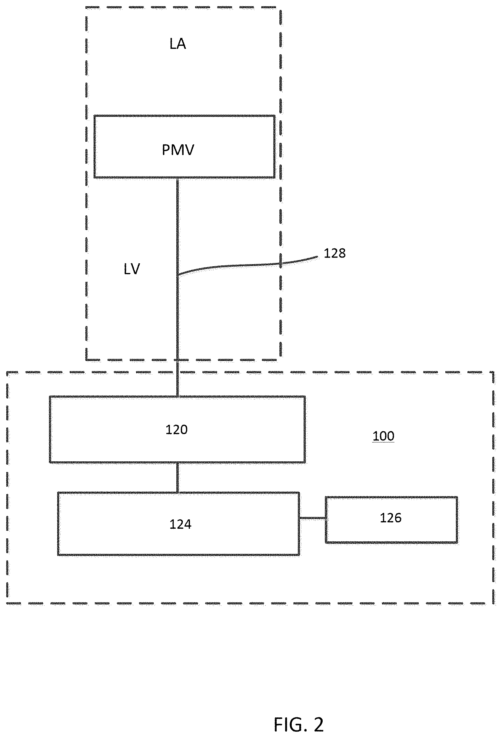
FIG. 2 is a schematic illustration of an epicardial anchor device, according to an embodiment.
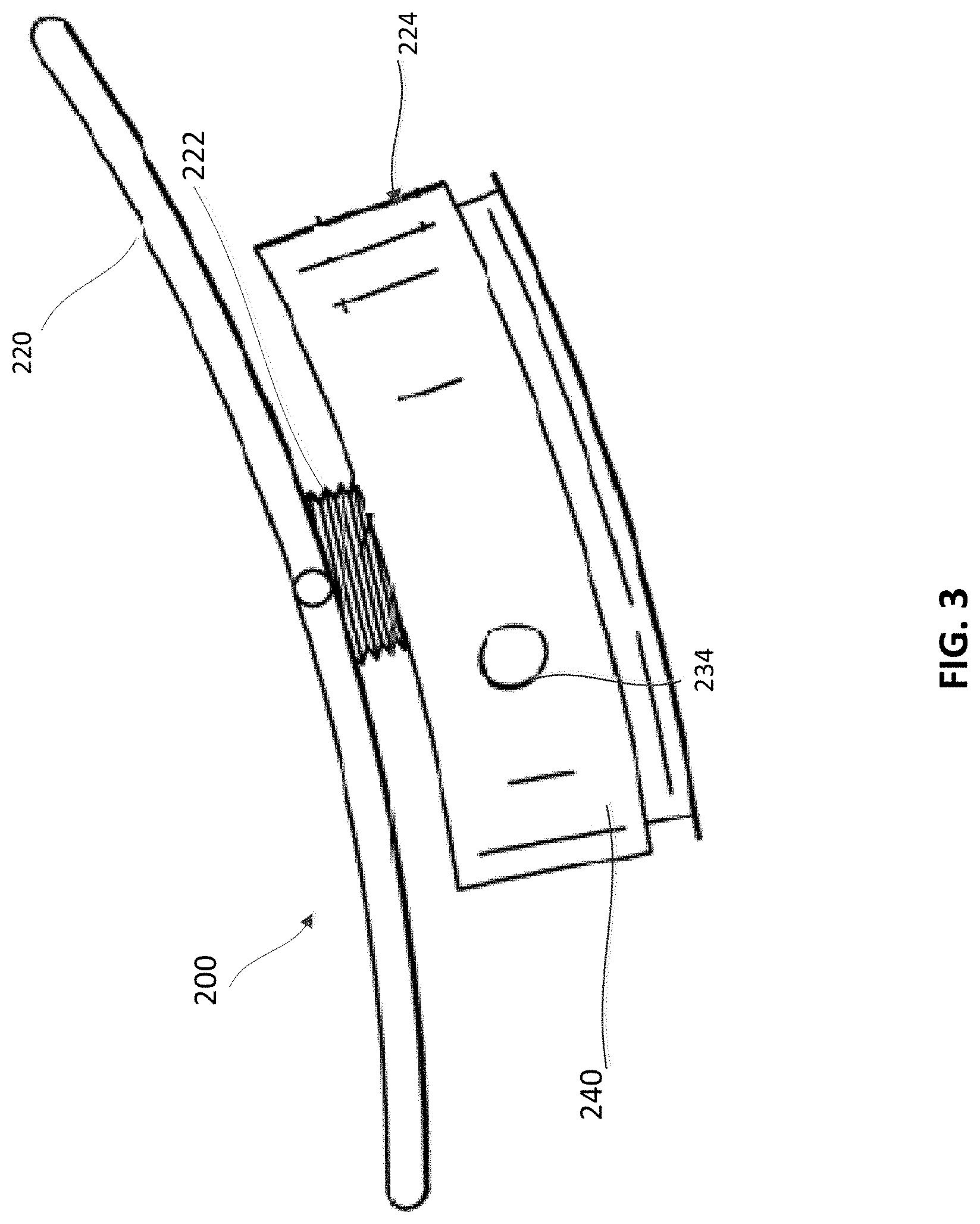
FIG. 3 is a side view of an epicardial anchor device, according to an embodiment.
FIG. 4 is an exploded side view of the epicardial anchor device of FIG. 3.
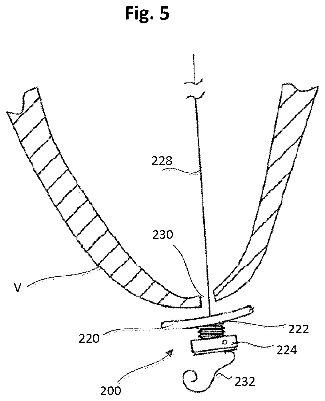
FIG. 5 is a side view of the epicardial anchor device of FIG. 3 shown disposed at a spaced distance from a puncture site in an epicardial surface of a ventricular wall and showing a sleeve gasket of the epicardial anchoring device in an uncompressed state or configuration.
FIG. 6 is a side view of the epicardial anchor device and ventricular wall of FIG. 5, shown with the anchoring device compressed against the puncture site and ventricular wall and the gasket in a compressed state or configuration.
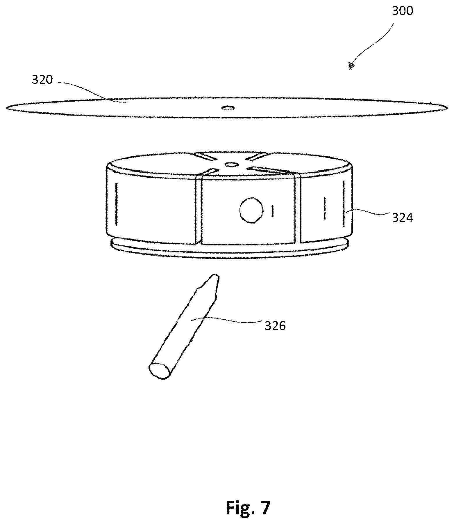
FIG. 7 is an exploded side view of an epicardial anchor device, according to another embodiment.
FIG. 8 is an exploded side view of an epicardial anchor device, according to another embodiment.
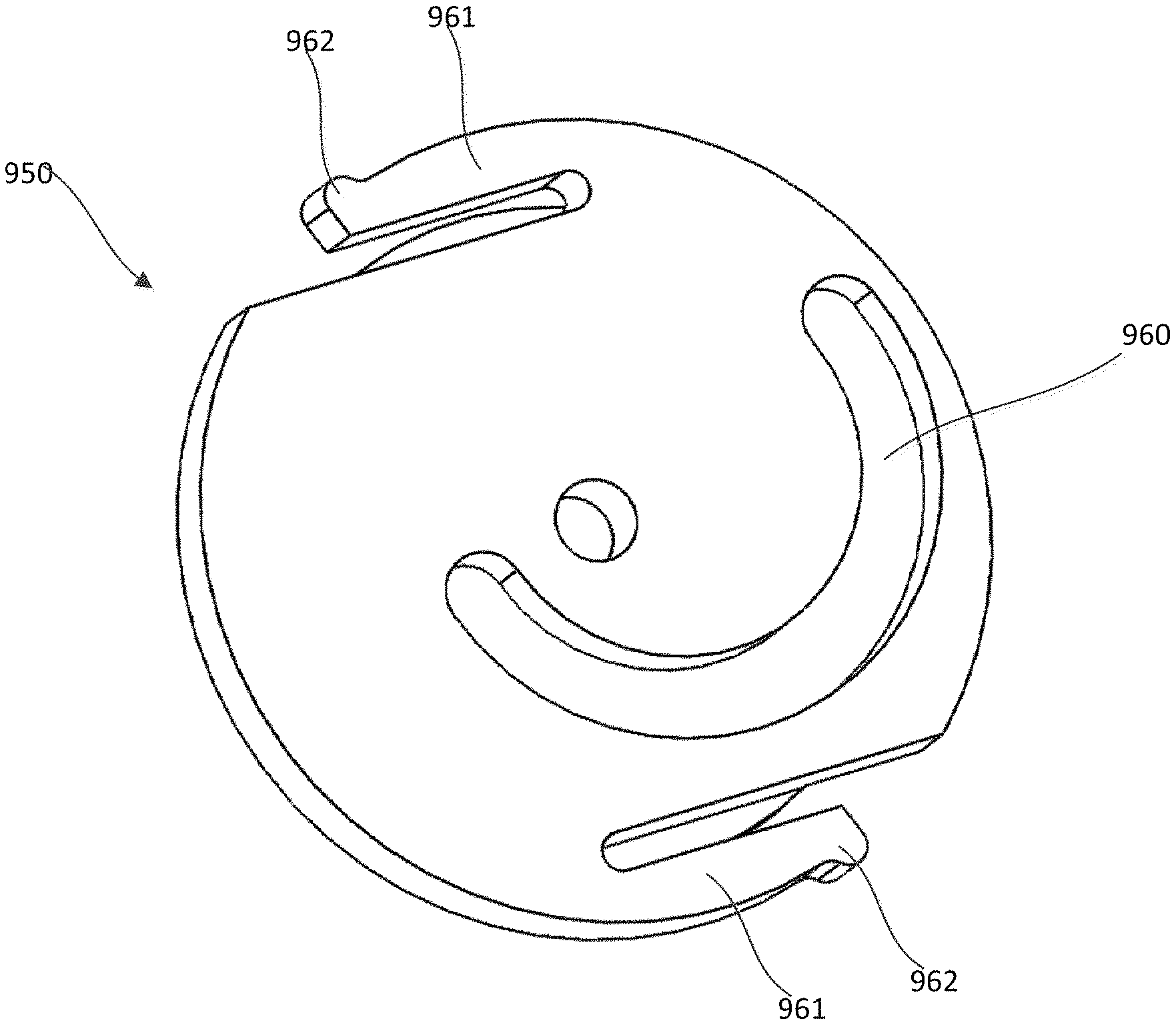
FIG. 9 is a top view of a flexible pad that can be included in an epicardial anchor device, according to an embodiment.
FIG. 10 is a perspective view of the flexible pad of FIG. 9 and a portion of a tether disposed therethrough.
FIG. 11 is a perspective view of a locking pin and a tether attachment member, according to an embodiment.
FIG. 12 is a bottom perspective view of the tether attachment member of FIG. 11.
FIG. 13 is a top perspective view of a tether attachment member that can be used within an anchor device, according to an embodiment, with a lever arm shown in a first position.
FIG. 14 is a cross-sectional perspective view of the tether attachment member of FIG. 13 with the lever arm shown in the first position.
FIG. 15 is a cross-sectional side view of the tether attachment member of FIG. 13 with the lever arm shown in the first position and a portion of a tether extending through the device.
FIG. 16 is a cross-sectional side view of the tether attachment member of FIG. 13 with the lever arm shown in a second position and a portion of a tether extending through the device.
FIG. 17 is a cross-sectional perspective view of a tether attachment member, according to an embodiment, with an access arm of the anchor device shown in a first position and a portion of a tether extending through the device.
FIG. 18 is a side-cross-sectional view of the tether attachment member of FIG. 17 shown with the access arm in the first position and the portion of a tether extending through the device.
FIG. 19 is a perspective view of the tether attachment member of FIG. 17 with a delivery device coupled thereto.
FIG. 20 is an enlarged view of the tether attachment member and a portion of the delivery device of FIG. 19.
FIG. 21 is a top perspective view of the tether attachment member of FIG. 17 with the access arm shown in a second position.
FIG. 22 is a top perspective view of an epicardial anchor device, according to another embodiment.
FIG. 23 is a top view of the epicardial anchor device of FIG. 22.
FIG. 24 is an exploded view of the epicardial anchor device of FIG. 22.
FIG. 25 is a cross-sectional perspective view of the epicardial anchor device of FIG. 22 with a locking pin of the device shown in a first position.
FIG. 26 is a cross-sectional side view of the epicardial anchor device of FIG. 20 with the locking pin of the device shown in the first position.
FIG. 27 is a cross-sectional bottom perspective view of the epicardial anchor device of FIG. 22 with the locking pin shown in a second position.
FIGS. 28 and 29 are a top perspective and a bottom perspective view, respectively, of a hub member of the epicardial anchor device of FIG. 22.
FIG. 30 is an enlarged top view of a portion of the pericardial pad device of FIG. 22.
FIG. 31 is a perspective view of the epicardial anchor device of FIG. 22 with a delivery device coupled thereto.
DETAILED DESCRIPTION
Apparatus and methods are described herein that can be used for securing and anchoring a prosthetic heart valve, such as, for example, a prosthetic mitral valve. Apparatus and methods described herein can also be used to close openings through the heart formed for example, when performing a procedure to implant a prosthetic heart valve. Apparatus and methods described herein can also be used to anchor other medical devices and/or to close punctures or openings in other body lumens formed during a diagnostic or therapeutic procedure.
In some embodiments, an apparatus includes a tether attachment member that includes a base member that defines at least a portion of a tether passageway through which a portion of a tether extending from a prosthetic heart valve can be received therethrough. The base member defines a locking pin channel that intersects the tether passageway. A locking pin is disposable within the locking pin channel and movable between a first position in which the locking pin is at a spaced distance from the tether passageway, and a second position in which the locking pin intersects the tether passageway and can engage the portion of a tether disposed therein to secure the tether to the tether attachment member.
In some embodiments, an apparatus includes a tether attachment member that includes a base member and a lever arm movably coupled to the base member. The base member and the lever arm collectively define a tether passageway through which a portion of a tether extending from a prosthetic heart valve can be received therethrough. The base member defines a locking pin channel that intersects the tether passageway and is in fluid communication therewith, and a locking pin is disposed within the locking pin channel. The lever arm is configured to be moved from a first position in which the portion of the tether can be inserted into the tether passageway, and a second position in which the locking pin secures a tether disposed within the tether passageway to the tether attachment member.
In some embodiments, an apparatus includes a tether attachment member that includes a base member and a hub member rotatably coupled to the base member. The base member and the hub each define at least a portion of a tether passageway through which a portion of a tether extending from a prosthetic heart valve can be received therethrough. The base member defines a locking pin channel that intersects the tether passageway and is in fluid communication therewith and a locking pin is disposed at least partially within the locking pin channel. The hub defines a cam channel in which a driver portion of the locking pin is received. The hub is configured to rotate relative to the base member such that the cam channel moves the locking pin linearly within the locking pin channel moving the locking pin from a first position in which the locking pin is at a spaced distance from the tether passageway, and a second position in which the locking pin intersects the tether passageway and engages a portion of a tether disposed therein to secure the tether to the tether attachment member.
In some embodiments, a method includes inserting into a tether passageway defined by a tether attachment member, a portion of a tether extending from a prosthetic heart valve. The tether attachment member is disposed adjacent an opening in a ventricular wall of a heart from which the tether extends. The tether attachment member is actuated such that a locking pin disposed within a locking pin channel defined by the tether attachment member intersects the tether passageway and engages a portion of the tether disposed within the tether passageway, securing the tether to the tether attachment member.
As used in this specification, the singular forms "a," "an" and "the" include plural referents unless the context clearly dictates otherwise. Thus, for example, the term "a member" is intended to mean a single member or a combination of members, "a material" is intended to mean one or more materials, or a combination thereof.
As used herein, the words "proximal" and "distal" refer to a direction closer to and away from, respectively, an operator of, for example, a medical device. Thus, for example, the end of the medical device closest to the patient's body (e.g., contacting the patient's body or disposed within the patient's body) would be the distal end of the medical device, while the end opposite the distal end and closest to, for example, the user (or hand of the user) of the medical device, would be the proximal end of the medical device.
In some embodiments, an epicardial pad system is described herein that can be used to anchor a compressible prosthetic heart valve replacement (e.g., a prosthetic mitral valve), which can be deployed into a closed beating heart using a transcatheter delivery system. Such an adjustable-tether and epicardial pad system can be deployed via a minimally invasive procedure such as, for example, a procedure utilizing the intercostal or subxyphoid space for valve introduction. In such a procedure, the prosthetic valve can be formed in such a manner that it can be compressed to fit within a delivery system and secondarily ejected from the delivery system into the target location, for example, the mitral or tricuspid valve annulus.
A compressible prosthetic mitral valve can have a shape, for example that features a tubular stent body that contains leaflets and an atrial cuff. This allows the valve to seat within the mitral annulus and be held by the native mitral leaflets. The use of a flexible valve attached using an apical tether can provide compliance with the motion and geometry of the heart. The geometry and motion of the heart are well-known as exhibiting a complicated biphasic left ventricular deformation with muscle thickening and a sequential twisting motion. The additional use of the apically secured ventricular tether helps maintain the prosthetic valve's annular position without allowing the valve to migrate, while providing enough tension between the cuff and the atrial trabeculations to reduce, and preferably eliminate, perivalvular leaking. The use of a compliant valve prosthesis and the special shape and features can help reduce or eliminate clotting and hemodynamic issues, including left ventricular outflow tract (LVOT) interference problems. Many known valves are not able to address problems with blood flow and aorta/aortic valve compression issues.
Structurally, the prosthetic heart valve can include: a self-expanding tubular frame having a cuff at one end (the atrial end); one or more attachment points to which one or more tethers can be attached, preferably at or near the ventricular end of the valve; and a leaflet assembly that contains the valve leaflets, which can be formed from stabilized tissue or other suitable biological or synthetic material. In one embodiment, the leaflet assembly may include a wire form where a formed wire structure is used in conjunction with stabilized tissue to create a leaflet support structure, which can have anywhere from 1, 2, 3 or 4 leaflets, or valve cusps disposed therein. In another embodiment, the leaflet assembly can be wireless and use only the stabilized tissue and stent body to provide the leaflet support structure, and which can also have anywhere from 1, 2, 3 or 4 leaflets, or valve cusps disposed therein.
The upper cuff portion may be formed by heat-forming a portion of a tubular nitinol structure (formed from, for example, braided wire or a laser-cut tube) such that the lower portion retains the tubular shape but the upper portion is opened out of the tubular shape and expanded to create a widened collar structure that may be shaped in a variety of functional regular or irregular funnel-like or collar-like shapes.
A prosthetic mitral valve can be anchored to the heart at a location external to the heart via one or more tethers coupled to an anchor device, as described herein. For example, the tether(s) can be coupled to the prosthetic mitral valve and extend out of the heart and be secured at an exterior location (e.g., the epicardial surface) with an anchor device, as described herein. An anchor device as described herein can be used with one or more such tethers in other surgical situations where such a tether may be desired to extend from an intraluminal cavity to an external anchoring site.
FIG. 1 is a cross-sectional illustration of the left ventricle LV and left atrium LA of a heart having a transcatheter prosthetic mitral valve PMV deployed therein and an epicardial anchor device EAD as described herein securing the prosthetic mitral valve PMV in place. FIG. 1 illustrates the prosthetic mitral valve PMV seated into the native valve annulus and held there using an atrial cuff AC of the prosthetic mitral valve PMV, the radial tension from the native leaflets, and a ventricular tether T secured with attachment portions Tp to the prosthetic mitral valve PMV and to the epicardial anchor EAD. Various embodiments of an epicardial anchor device are described in more detail below with reference to specific embodiments.
FIG. 2 is a schematic illustration of an epicardial anchor device 100 (also referred to herein as "anchor device" or "epicardial anchor") according to an embodiment. The anchor device 100 can be used to anchor or secure a prosthetic mitral valve PMV deployed between the left atrium and left ventricle of a heart. The anchor device 100 can be used, for example, to anchor or secure the prosthetic mitral valve PMV via a suturing tether 128 as described above with respect to FIG. 1. The anchor device 100 can also seal a puncture formed in the ventricular wall (not shown in FIG. 2) of the heart during implantation of the prosthetic mitral valve PMV. The anchor device 100 can also be used in other applications to anchor a medical device (such as any prosthetic atrioventricular valve or other heart valve) and/or to seal an opening such as a puncture.
The anchor device 100 can include a pad (or pad assembly) 120, a tether attachment member 124 and a locking pin 126. In some embodiments, the anchor device 100 can include a sleeve gasket (not shown in FIG. 2) as described with respect to FIGS. 3-6. The pad 120 can contact the epicardial surface of the heart and can be constructed of any suitable biocompatible surgical material. The pad 120 can be used to assist the sealing of a surgical puncture formed when implanting a prosthetic mitral valve. In some embodiments, the pad 120 can include a slot that extends radially to an edge of the pad 120 such that the pad 120 can be attached to, or disposed about, the tether 128 by sliding the pad 120 onto the tether 128 via the slot. Such an embodiment is described below with respect to FIGS. 9 and 10.
In some embodiments, the pad 120 can be made with a double velour material to promote ingrowth of the pad 120 into the puncture site area. For example, pad or felt pledgets can be made of a felted polyester and may be cut to any suitable size or shape, such as those available from Bard.RTM. as PTFE Felt Pledgets having a nominal thickness of 2.87 mm. In some embodiments, the pad 120 can be larger in diameter than the tether attachment member 124. The pad 120 can have a circular or disk shape, or other suitable shapes.
The tether attachment member 124 can provide the anchoring and mounting platform to which one or more tethers 128 can be coupled (e.g., tied or pinned). The tether attachment member 124 can include a base member (not shown) that defines at least a portion of a tether passageway (not shown) through which the tether 128 can be received and pass through the tether attachment member 124, and a locking pin channel (not shown) through which the locking pin 126 can be received. The locking pin channel can be in fluid communication with the tether passageway such that when the locking pin 126 is disposed in the locking pin channel, the locking pin 126 can contact or pierce the tether 128 as it passes through the tether passageway as described in more detail below with reference to specific embodiments.
The locking pin 126 can be used to hold the tether 128 in place after the anchor device 100 has been tightened against the ventricular wall and the tether 128 has been pulled to a desired tension. For example, the tether 128 can extend through a hole in the pad 120, through a hole in a sleeve gasket (if the anchor device includes a sleeve gasket), and through the tether passageway of the tether attachment member 124. The locking pin 126 can be inserted or moved within the locking pin channel 134 such that it pierces or otherwise engages the tether 128 as the tether 128 extends through the tether passageway of the tether attachment member 124. Thus, the locking pin 126 can intersect the tether 128 and secure the tether 128 to the tether attachment member 124.
The tether attachment member 124 can be formed with, a variety of suitable biocompatible material. For example, in some embodiments, the tether attachment member 124 can be made of polyethylene, or other hard or semi-hard polymer, and can be covered with a polyester velour to promote ingrowth. In other embodiments, the tether attachment member 124 can be made of metal, such as, for example, Nitinol.RTM., or ceramic materials. The tether attachment member 124 can be various sizes and/or shapes. For example, the tether attachment member 124 can be substantially disk shaped.
In some embodiments the tether attachment member 124 can include a lever arm (not shown in FIG. 2) that can be moved between an open position to load the tether 128 within the tether attachment member 124, and a closed position to secure the tether 128 to the tether attachment member 124. For example, in some embodiments, when the lever arm is moved to the closed position, the tether passageway is brought into an intersecting relation with the locking pin channel such that the locking pin 126 engages the tether 128 disposed within the tether passageway. In some embodiments, when the lever arm is in the open position, a tool can be used to move the locking pin within the locking pin channel such that the locking pin engages the tether 128 disposed within the tether passageway. In such an embodiment, after the locking pin 126 secures the tether 128, the lever arm can be moved to the closed position.
In some embodiments, the tether attachment member 124 can include a hub that is movably coupled to the base member of tether attachment member 124. The hub can define a channel that can receive a portion of the locking pin (or locking pin assembly) 126 such that as the hub is rotated, the hub acts as a cam to move the locking pin 126 linearly within the locking pin channel. As with previous embodiments, as the locking pin 126 is moved within the locking pin channel, the locking pin can engage or pierce the tether 128 disposed within the tether passageway and secure the tether 128 to the tether attachment member 124. Such an embodiment is described herein with respect to FIGS. 22-31.
In use, after a PMV has been placed within a heart, the tether extending from the PMV can be inserted into the tether passageway of the anchor device 100 and the tension on the tether attachment device can be adjusted to a desired tension. Alternatively, in some cases, the tether extending from the PMV can be coupled to the anchor device 100 prior to the PMV being placed within the heart. The anchor device 100 (e.g., some portion of the anchor device such as the tether attachment member 124, or the lever arm or hub depending on the particular embodiment) can be actuated such that the locking pin 126 intersects the tether passageway and engages a portion of the tether disposed within the tether passageway, securing the tether to the tether attachment member. In some embodiments, prior to inserting the tether into the tether passageway, the anchor device 100 can be actuated to configure the anchor device 100 to receive the tether. For example, if the tether attachment member includes a lever arm movably coupled to the base member, the lever arm may need to be moved to an open position to allow the tether to be inserted. In some embodiments, the anchor device 100 can be actuated by rotating a hub relative to a base member of the tether attachment member 124 such that the locking pin 126 is moved from a first position in which the locking pin is spaced from the tether passageway and a second position in which the locking pin intersects the tether passageway and engages or pierces the portion of the tether.
One implementation of the epicardial anchor device 100 is shown in FIGS. 3-6. An epicardial anchor device 200 (also referred to herein as "anchor device" or "epicardial anchor") can include a flexible pad 220, a sleeve gasket 222, a tether attachment member 224 and a locking pin 226 (shown in FIG. 4). The anchor device 200 can be used to anchor or secure a prosthetic mitral valve (not shown in FIGS. 3-6) via a suturing tether 228 shown in FIGS. 5 and 6. The anchor device 200 can also seal a puncture 230 formed in the ventricular wall V (see FIGS. 5 and 6) of the heart during implantation of the prosthetic mitral valve.
The flexible pad 220 (also referred to herein as "pad") can contact the epicardial surface of the heart and can be constructed of any suitable biocompatible surgical material. The pad 220 can be used to assist the sealing of a surgical puncture (e.g., puncture 230) formed when implanting a prosthetic mitral valve. The pad 220 can be made with the same or similar materials as described above for pad 120, and can be various sizes and shapes. The pad 220 is shown as having a circular or disk shape, however it should be understood that other suitable shapes can alternatively be used. The pad 220 defines a hole 225 (see FIGS. 4 and 6) through which the tether 228 (shown in FIGS. 5 and 6) can be received as described in more detail below.
The sleeve gasket 222 can be disposed between the pad 220 and the tether attachment member 224 and can be used to seal a gap or leakage that may occur between the pad 220 and the tether attachment member 224. The sleeve gasket 222 can be made of, for example, a flexible material such that it can be compressed when the tether attachment member 224 and/or pad 220 are tightened against the puncture site, e.g. against the ventricular wall. The sleeve gasket 222 may be a separate component coupled to the pad 220 and the tether attachment member 224 or can be formed integrally or monolithically with the pad 220 and/or the tether attachment member 224. The sleeve gasket 222 can be used to prevent hemodynamic leakage that may flow along the path of the suturing tether 228. The sleeve gasket 222 can also define a hole (not shown) through which the tether 228 can be received.
The tether attachment member 224 can provide the anchoring and mounting platform to which one or more tethers 228 (see FIGS. 5 and 6) may be coupled (e.g., tied). The tether attachment member 224 includes a base member 240 that defines an axial tether passageway 235 through which the tether 228 can be received and pass through the tether attachment member 224, and a locking pin channel 234 through which the locking pin 226 can be received. The locking pin channel 234 can be in fluid communication with the tether passageway 235 such that when the locking pin 226 is disposed in the locking pin channel 234, the locking pin 226 can contact the tether 228 as it passes through the tether passageway 235 as described in more detail below. The locking pin 226 can be used to hold the tether 228 in place after the anchor device 200 has been tightened against the ventricular wall V. For example, the tether 228 can extend through the hole 225 of the pad 220, through the hole (not shown) of the sleeve gasket 222, and through the tether passageway 235 of the tether attachment member 224. The locking pin 226 can be inserted through the locking pin channel 234 such that it pierces the tether 228 as the tether 228 extends through the tether passageway 235 of the tether attachment member 224. Thus, the locking pin 226 can laterally intersect the tether 228 and secure the tether 228 to the tether attachment member 224.
The tether attachment member 224 can be made of any suitable biocompatible material. For example, in some embodiments, the tether attachment member 224 can be made of polyethylene, or other hard or semi-hard polymer, and can be covered with a polyester velour to promote ingrowth. In other embodiments, the tether attachment member 224 can be made of metal, such as, for example, Nitinol.RTM., or ceramic materials. The tether attachment member 224 can be various sizes and/or shapes. For example, the tether attachment member 224 can be substantially disk shaped.
In some embodiments, the tether attachment member 224 can be substantially disk shaped and have a diameter between, for example, 1.0-3.0 cm. In other embodiments, the tether attachment member 224 can have a diameter, for example, between 0.2-5.0 cm. For example, a larger size tether attachment member 224 may be desirable to use in, for example, a hernia repair, gastrointestinal repairs, etc.
The disk shape of the tether attachment member 224 used to capture and anchor a suture can also be used with little or no trauma to the tissue at the site of the anchor, unlike suture anchors that bore into tissue with screws or barbs. Further, the disk shaped tether attachment member 224 can be easily and quickly slid over the tether 228, instead of using stitches, which can allow for the effective permanent closure of large punctures. Surgically closing large punctures by sewing can be time consuming and difficult. When closing a puncture in the heart, adding the difficulty of requiring a surgeon to sew the puncture closed can increase the likelihood of life threatening complications to the patient. This is especially so in a situation where a prosthetic heart valve is delivered and deployed without opening the chest cavity using transcatheter technologies. Sewing a ventricular puncture closed in this situation may be undesirable.
FIGS. 5 and 6 illustrate the tether 228 extending through the puncture site 230 within a left ventricular wall V of a heart and coupled to the anchor device 200. FIG. 5 illustrates the anchor device 200 prior to being tightened against the epicardial surface of the ventricular wall V, and the sleeve gasket 222 in an uncompressed state or configuration. The tether 228 can optionally be wound around the tether attachment member 224 to further improve anchoring.
FIG. 6 illustrates the anchor device 200 tightened against the epicardial surface of the ventricular wall V. As shown in FIG. 6, the anchor device 200 can be compressed against the puncture site 230 and contact the epicardial surface. An end portion 232 (shown in FIG. 5) of the tether 228 can be trimmed after the tether 228 has been secured to the tether attachment member 224 or after the anchor device 200 has been secured against the epicardial surface.
FIG. 7 illustrates an embodiment of an epicardial anchor device 300 (also referred to herein as "anchor device" or "epicardial anchor") that is similar to the anchor device 200 except the anchor device 300 does not include a sleeve gasket (e.g., sleeve gasket 222 described above). The anchor device 300 can include a flexible pad 320, a tether attachment member 324 and a locking pin 326, which can be configured the same as or similar to the flexible pad 220, the tether attachment member 224 and the locking pin 226, respectively, described above. The anchor device 300 can be used the same as or similar to anchor device 200 to secure a prosthetic mitral valve (not shown) via a suturing tether (not shown). The anchor device 300 may be desirable to use, for example, when an anti-leakage sleeve is unnecessary to prevent hemodynamic leakage that may flow along the path of the suturing tether.
FIG. 8 illustrates an embodiment of an epicardial anchor device 400 (also referred to herein as "anchor device" or "epicardial anchor") that is similar to the anchor device 200 and the anchor device 300 except the anchor device 400 does not include a pad (e.g., pads 220 and 320). The anchor device 400 can include a tether attachment member 424, a sleeve gasket 422 and a locking pin 426, which can be configured the same as or similar to the tether attachment member 224, the sleeve gasket 222 and the locking pin 226, respectively, described above. The anchor device 400 can be used to anchor or secure a prosthetic mitral valve (not shown) via a tether (not shown) in the same or similar manner as described above for previous embodiments. The anchor device 400 may be desirable to use, for example, when a flexible pad is unnecessary, for example, when the tether is moved to a new location. In such a case, the ventricular puncture would be small (e.g., a small diameter) and may not require the pad for bleeding control.
FIGS. 9 and 10 illustrate an embodiment of a pad 520 that can be included in an epicardial anchor device as described herein. The pad 520 defines an axial hole 525 and a slot 537 that communicates with hole 525. The slot 537 extends radially to an outer edge of the pad 520 such that the pad 520 can be disposed about or removed from a tether 528 (see FIG. 10) without sliding the pad 520 down the length of tether 528. For example, the pad 520 can be disposed about the tether 528 by laterally sliding the pad 520 from the side such that the tether is inserted into the slot 537 and positioned within the opening 525 of the pad 520. The pad 520 can be secured to the tether with, for example, pins, clamps, etc.
To remove the pad 520, the pad 520 can similarly slide off from the side, for example, outside of the apex of the ventricle of the heart. Thus, the pad 520 can be removed without removing the entire anchor device. The pad 520 can be formed with the same or similar materials as described above for previous embodiments (e.g., pad 220, 320, 420), and can be used to close a puncture site (e.g., in a ventricular wall) as described above.
The pad 520 can also enable the use of an introducer sheath at the apex, which would limit the amount of motion and passes through the apex. For example, when the sheath is pulled back, a slotted pad 520 can be slid in from the side allowing control of the tether tension during sheath removal. The pad 520 with slot 537 can also be used independent of a sheath as described above.
FIGS. 11 and 12 illustrate an embodiment of a tether attachment member 624 that can be included within an anchor device as described herein. Various features described herein for tether attachment member 624 can also be included in the tether attachment members described herein for other embodiments (e.g., 124, 224, 324, 424). As described above, a locking pin 626 (shown in FIG. 11) can be used to secure a tether/suture to the tether attachment member 624 in a similar manner as described above for previous embodiments.
The tether attachment member 624 is shown having a disk shape and can include a base member 640 that defines a winding channel 632, an axial tether passageway 635, radial channels 633, and a locking pin channel 634 through which the locking pin 626 can be received. The base member 640 also defines a proximal opening 615 and a distal opening 617 each communicating with the tether passageway 835. The base member 640 can include a chamfered edge or lead-in portion 627 at the proximal opening 615, and a chamfered edge or lead-in portion 629 at the distal opening 617 to allow a suture (e.g., tether) to be easily threaded into the tether passageway 635 and reduce lateral cutting force of the tether attachment member 624 against the suture. The radial channels 633 can allow a user to quickly capture and seat a tether (not shown) that is intended to be anchored. The winding channel 632 can allow a user to quickly wind tether(s) around tether attachment member 624. The use of winding channel 632 with radial channel(s) 633 can allow a user to quickly anchor the tether while permitting the user to unwind and recalibrate the anchor device to adjust the tension on the tether (not shown) as appropriate for a particular use.
FIGS. 13-16 illustrate a portion of another embodiment of an epicardial anchor device 700. The epicardial anchor device 700 includes a tether attachment member 724 and a flexible pad or fabric member (not shown in FIGS. 13-16). The tether attachment member 724 includes a base member 740 that defines a locking pin channel 734 that can receive therein a locking pin 726 in a similar manner as described above for previous embodiments and a circumferential pad channel 742. The pad channel 742 can be used to secure the flexible pad or fabric member (not shown in FIGS. 13-16) of the epicardial anchor device 700 to the tether attachment member 724. For example, the flexible pad can be disposed on a distal end portion of the tether attachment member 724 such that when the anchor device 700 is secured to a ventricular wall as described above for previous embodiments, the flexible pad contacts the ventricular wall.
The tether attachment member 724 also defines tether passageway 735 through which a tether 728 (see, e.g., FIGS. 15 and 16) can be received, and a proximal opening 715 and a distal opening 717 each in communication with the tether passageway 735. A chamfered edge or lead-in portion 729 is included at or near the distal opening 717 to allow a tether 728 (see e.g., FIGS. 15 and 16) to be easily threaded into the tether passageway 735 and reduce lateral cutting force of the tether attachment member 724 against the tether 728.
A lever arm 738 is coupled to the base member 740 that collectively with the base member 740 defines a tether passageway 735. The lever arm 738 can be moved between a first position, as shown in FIG. 16, in which the lever arm 738 is biased by a spring member 739 into a down position, and a second position, as shown in FIGS. 13-15, in which the lever arm 738 is placed in an extended position to allow the tether 728 to be placed within the tether passageway 735. For example, the lever arm 738 can be rotated in the direction of arrow A shown in FIG. 15 to move the lever arm 738 to its second or extended position. In some cases, a suture or cord can be used to pull the lever arm 738 to the extended second position.
When in the first position, as shown, for example, in FIGS. 14 and 15, a tip of the locking pin 726 is disposed at a spaced distance from the lever arm 738 and the tether passageway 735. When the locking pin 726 is spaced from the tether passageway 735, the tether 728 can be inserted into the tether passageway 735 as shown in FIG. 15. The tether 728 can then be tightened to a desired tension and the lever arm can then be released such that it is biased back to the first position, as shown in FIG. 16. When the lever arm 738 is moved (e.g., biased) to the first position, and with the tether 728 extending through the tether passageway 735, the locking pin 726 pierces or intersects with the tether 728 and the tip of the locking pin is then disposed within a cavity 736 defined by the lever arm 738 securing the tether 728 to the tether attachment member 724.
FIGS. 17-21 illustrate a portion of another embodiment of an epicardial anchor device 800 that includes a tether attachment member 824 and a flexible pad or fabric member (not shown in FIGS. 17-21). The tether attachment member 824 includes a base member 840 and a lever arm 838 pivotally coupled to the base member 840. The base member 840 defines a circumferential pad channel 842 in which the flexible pad can be coupled to the tether attachment member 824. For example, the flexible pad can be disposed on a distal end portion of the tether attachment member 824 such that when the anchor device 800 is secured to a ventricular wall as described above for previous embodiments, the flexible pad contacts the ventricular wall.
The lever arm 838 and the base member 840 collectively define a tether passageway 835 through which a tether 828 can be received, as shown in FIG. 17. The base member 840 also defines a distal opening 817 and an opening 815 each in fluid communication with the tether passageway 835. The tether 828 can be inserted through the distal opening 817 (the side to be implanted closest to the ventricular wall) and extend through a portion of the tether passageway 835 defined by the base member 840, and through a portion of the tether passageway 835 defined by the lever arm 838, and exit the opening 815. As with previous embodiments, the base member 840 includes a chamfered edge or lead-in portion 829 at the distal opening 817 of the tether passageway 835 to allow the tether 828 to be easily threaded into the tether passageway 835 and reduce lateral cutting force of the tether attachment member 824 against the tether 828.
The lever arm 838 defines a locking pin channel 844 in which a locking pin 826 can be movably disposed. The locking pin 826 includes a driver portion 846 and a piercing portion 849. As shown in FIGS. 17 and 18, the locking pin channel 844 includes portions with varying diameters in which the driver portion 846 of the locking pin 826 can be movably disposed. For example, the driver portion 846 can be threadably coupled to the inner walls of the locking pin channel 844 such that the locking pin 826 can be moved between a first position, shown in FIG. 17, in which the driver portion 846 is disposed within a portion 839 of the locking pin channel 844 and the piercing portion 849 is spaced from the tether passageway 835, and a second position in which the driver portion 846 is disposed within a portion 845 (shown in FIGS. 17 and 18) of the locking pin channel 834, and the piercing portion 849 extends through the tether passageway 835, engaging or piercing the tether 828. The lever arm 838 also defines an opening 847 that communicates with the locking pin channel 844 and can receive a driving tool that can be used to move the locking pin 826 within the locking pin channel 844 as described in more detail below.
The lever arm 838 can be moved (e.g., rotated, pivoted) between a first or open position, as shown, for example, in FIGS. 17 and 18, in which the lever arm 838 extends in a proximal direction from the base member 840, and a second or closed position as shown in FIG. 21, in which a proximal surface 819 of the lever arm 838 is substantially flush with a proximal surface 821 of the base member 840. When the lever arm 838 is in the first or open position, a delivery tool 848 can be coupled to the lever arm 828 as shown in FIGS. 19 and 20. The delivery tool 848 can include a driver 849 shown in FIG. 18 (e.g., a screw driver) that can engage the driver portion 846 of the locking pin 826 to move the locking pin 826 within the locking pin channel 834.
In operation, the tether 828 can be inserted into the tether passageway 835 and extend out of the opening 815 and within the delivery tool 848. The tether 828 can then be tightened to a desired tension. With the tether 828 at the desired tension, the driver 849 of the delivery tool 848 can then move the locking pin 826 from the first position, as shown in FIG. 17 to the second position in which the piercing portion 849 pierces or engages the tether 828, securing the tether 828 to the tether attachment member 824. For example, the driver 849 of the delivery tool 848 can threadably move the locking pin 826 from the first position to the second position. After the tether 828 is secured to the tether attachment member 824, the delivery tool 849 can be removed and the lever arm 838 can be moved to the second or closed position as shown in FIG. 21.
FIGS. 22-30 illustrate an epicardial anchor device according to another embodiment. An epicardial anchor device 900 includes a tether attachment member 924, a pad assembly 920, a tube member 955 and a tube cover member 956. The tether attachment member 924 includes a base member 940, a hub 950, a retaining ring 952, a locking pin assembly 926, and a pin member 953. The locking pin assembly 926 includes a driver portion 946 and a piercing portion 949. The base member 940 defines a circumferential pad channel 942, a retaining channel 951 and a locking pin channel 934. The pad channel 942 can be used to couple the pad assembly 920 to the tether attachment member 924. The retaining channel 951 can receive an outer edge of the retaining ring 952, which is used to retain the hub 950 to the base member 940. The base member 940 also defines cutouts or detents 943, as shown for example, in FIGS. 23, 25 and 30.
The tube member 955 is coupled to the base member 940 and the base member 940, the hub 950 and the tube member 955 collectively define a tether passageway 935 through which a tether (not shown) can be received. The cover member 956 can be formed with a fabric material, such as for example, Dacron.RTM.. The tether channel 935 intersects the locking pin channel 934 and is in fluid communication therewith.
The pad assembly 920 includes a top pad portion 958, a bottom pad portion 959 and a filler member 957 disposed therebetween. The top pad portion 958 and the bottom pad portion 959 can each be formed with, for example, a flexible fabric material. The top pad portion 958 and the bottom pad portion 959 can each define a central opening through which the tube member 955 can pass through. A portion of the top pad portion 958 is received within the channel 942 of the base member 940 as shown, for example, in FIGS. 25-27.
An outer perimeter portion of the hub 950 is received within the retaining channel 951 such that the entire hub 950 can rotate relative to the base member 940 to actuate the locking pin assembly 926 as described in more detail below. As shown, for example, in FIGS. 28 and 29, the hub 950 includes arms 961 with protrusions 962. The protrusions 962 can be received within cutouts 943 of the base member 940 and act as a stop or limit to the rotation of the hub 950. The slots 963 defined by the hub 950 enable the arms 961 to flex and allow the protrusions 962 to be moved in and out of the cutouts 943. As shown, for example, in FIGS. 27 and 29 the hub 950 defines a curved channel 960 on a bottom portion of the hub 950. The curved channel 960 is asymmetrical (or spiral) and receives the driver portion 946 of the locking pin assembly 926. As the hub 950 is rotated relative to the base member 940, the hub 950 acts as a cam to move the locking pin assembly 926 linearly within the locking pin channel 934. The locking pin assembly 926 can be moved from a first position in which the piercing portion 949 is disposed outside of the tether passageway 935 as shown in FIGS. 25 and 26, and a second position in which the piercing portion 949 extends through the tether passageway 935 as shown in FIG. 27. The pin member 953 (see, e.g., FIG. 26) can be formed with a metal material that is more radio-opaque than the other components of the anchor device and thus visible to the user (e.g. physician) using conventional imaging modalities to enable the user to confirm that the locking pin assembly 926 has been fully moved to the second position.
In use, when the locking pin assembly 926 is in the first position, a tether (not shown) coupled to, for example, a prosthetic mitral valve and extending through a puncture site in the ventricular wall of a heart can be inserted through the tether passageway 935. The hub 950 can then be rotated 180 degrees to move the locking pin assembly 926 linearly within the locking pin channel 934 such that the piercing portion 949 extends through the tether passageway 935 and engages or pierces the tether, securing the tether to the tether attachment member 924. For example, when the locking pin is in the first position, the protrusions 962 of the hub 950 are each disposed within one of the cutouts 943 of the base member 940 (i.e., a first protrusion is in a first cutout, and a second protrusion is in a second cutout). The hub 950 can then be rotated 180 degrees such that the protrusions 962 are moved out of the cutouts 943 of the base member 940 and at the end of the 180 degrees the protrusions 962 are moved into the other of the cutouts 943 of the base member 940 (i.e., the first protrusion is now in the second cutout, the second protrusion is now in the first cutout).
The base member 940 can also include cutout sections 966 and define side openings 967 (see, e.g., FIGS. 22 and 23) that can be used to couple a delivery device to the epicardial anchor device 900. For example, FIG. 31 illustrates a delivery device 948 having coupling arms 968 and coupling pins (not shown) extending inwardly from the arms 968. The side openings 967 can receive the coupling pins and the cutout sections 966 can be engaged by the coupling arms 968.
While various embodiments have been described above, it should be understood that they have been presented by way of example only, and not limitation. Where methods described above indicate certain events occurring in certain order, the ordering of certain events may be modified. Additionally, certain of the events may be performed concurrently in a parallel process when possible, as well as performed sequentially as described above
Where schematics and/or embodiments described above indicate certain components arranged in certain orientations or positions, the arrangement of components may be modified. While the embodiments have been particularly shown and described, it will be understood that various changes in form and details may be made. Any portion of the apparatus and/or methods described herein may be combined in any combination, except mutually exclusive combinations. The embodiments described herein can include various combinations and/or sub-combinations of the functions, components, and/or features of the different embodiments described.
* * * * *
References
D00000
D00001
D00002
D00003
D00004
D00005
D00006
D00007
D00008
D00009
D00010
D00011
D00012
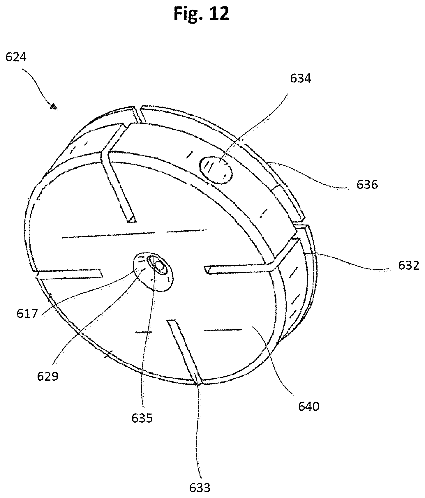
D00013
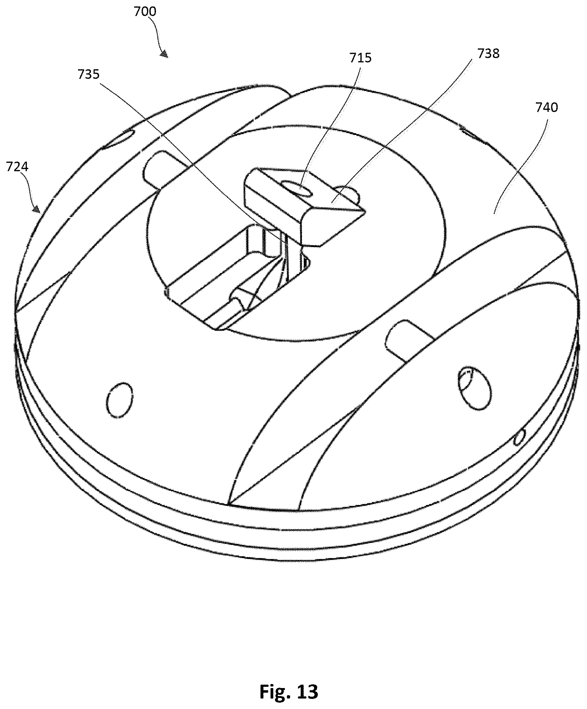
D00014

D00015

D00016

D00017

D00018
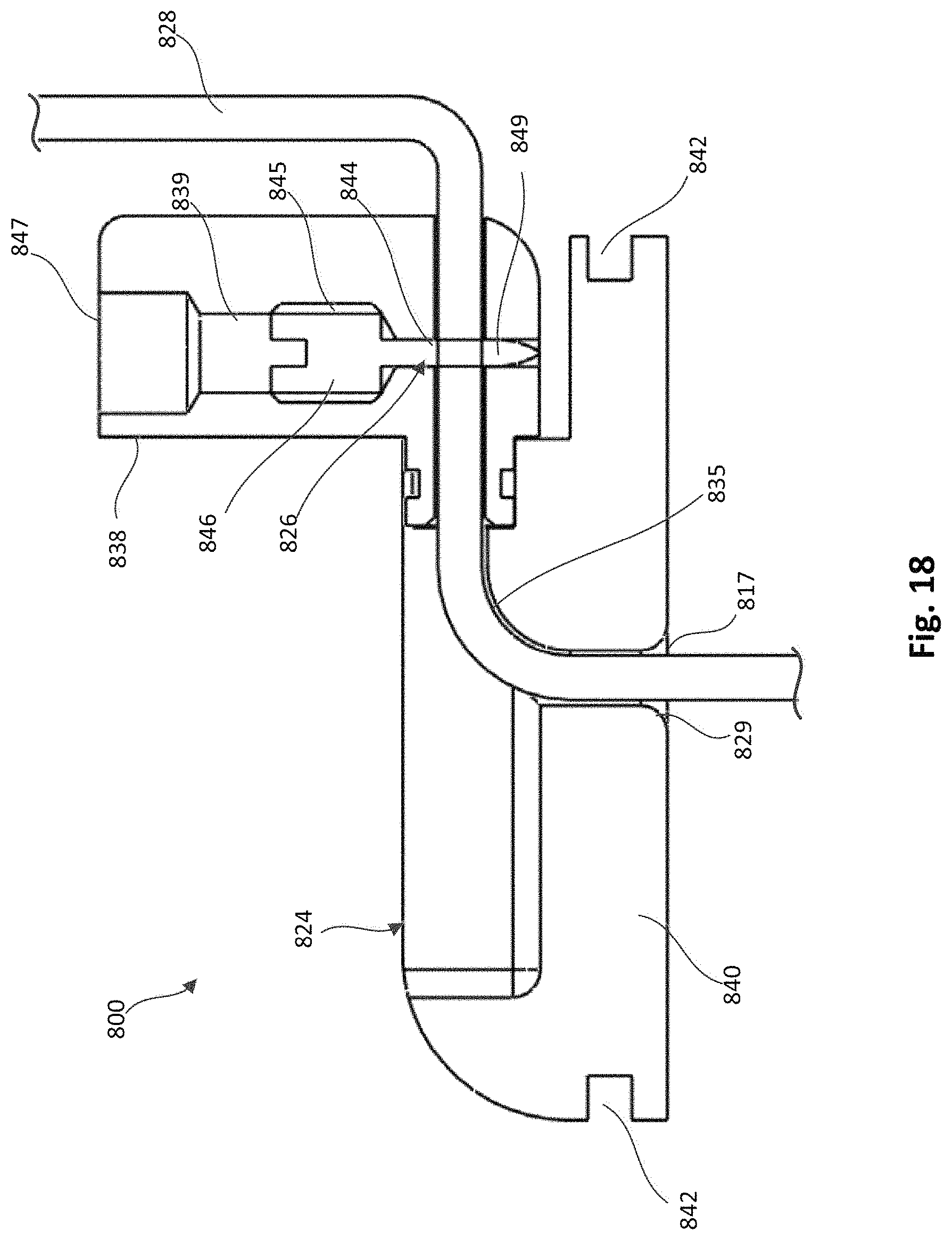
D00019

D00020
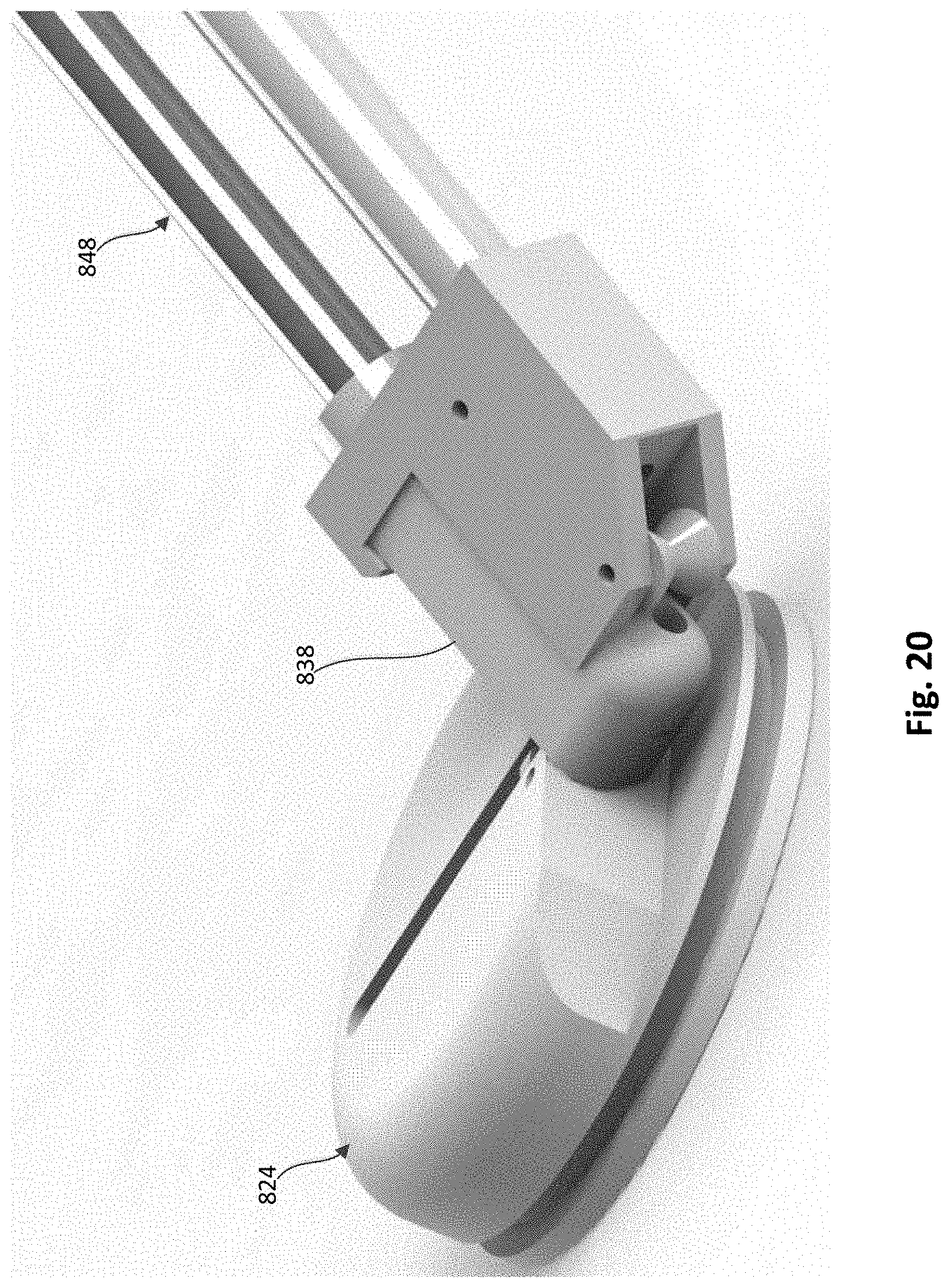
D00021

D00022
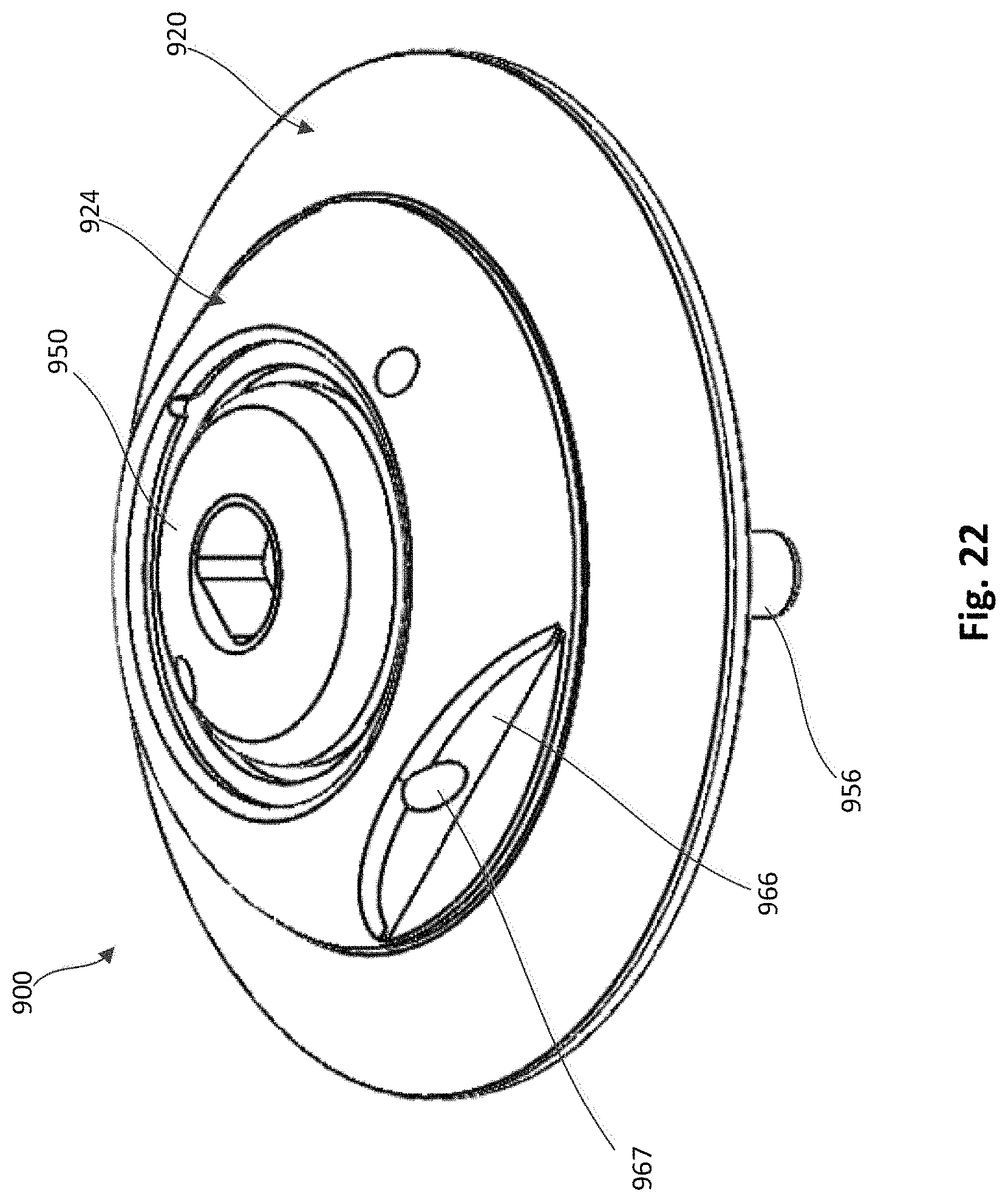
D00023
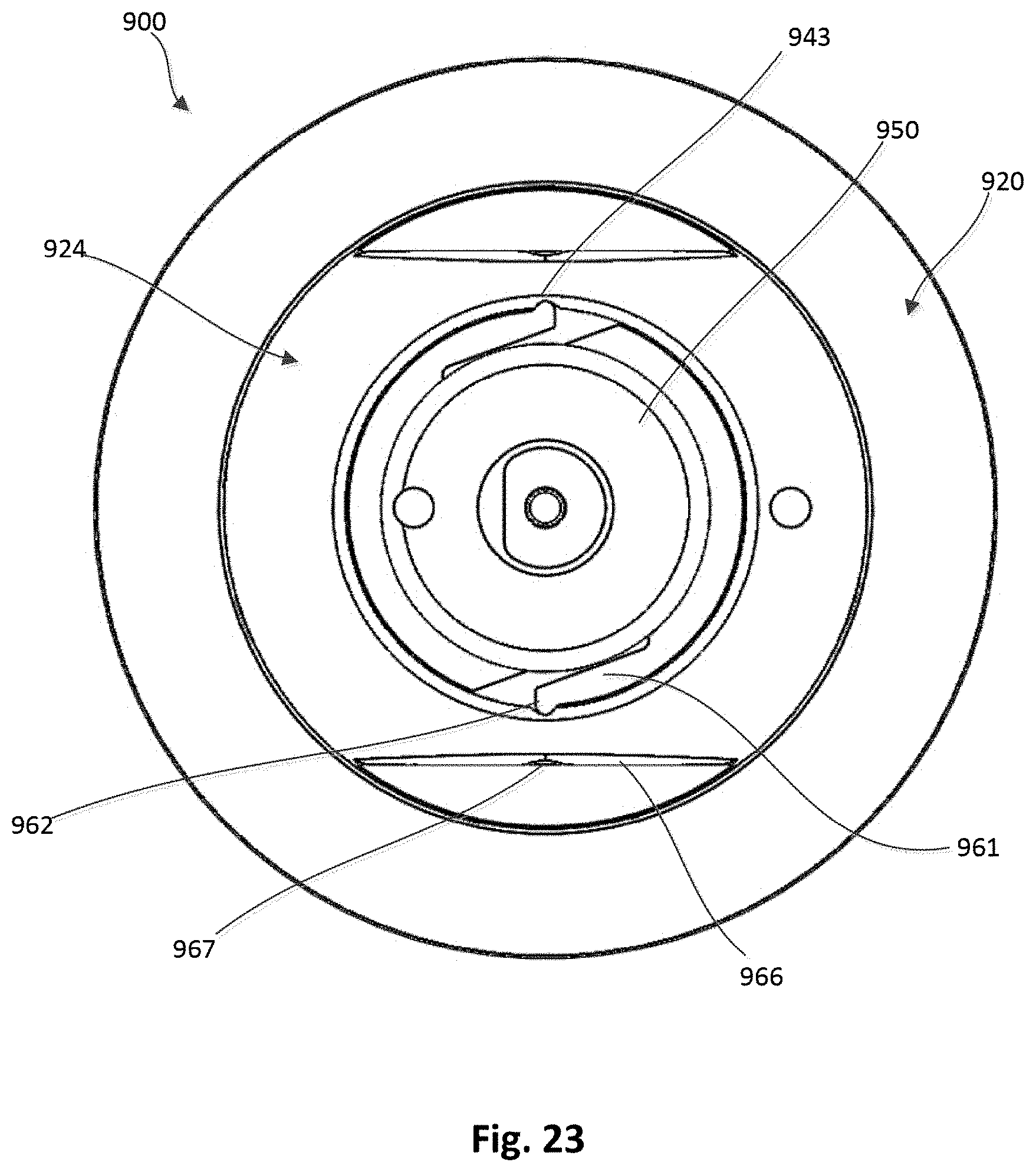
D00024

D00025

D00026

D00027

D00028
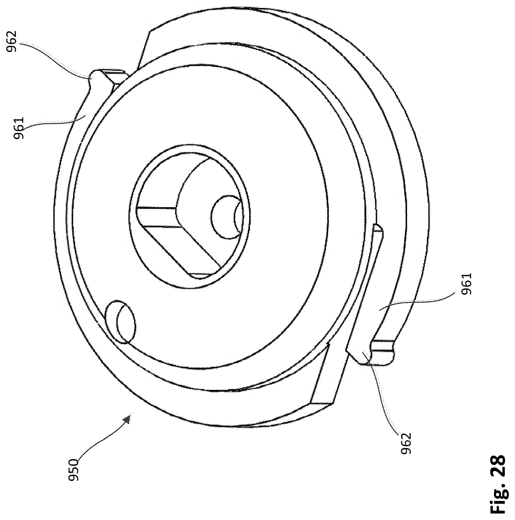
D00029
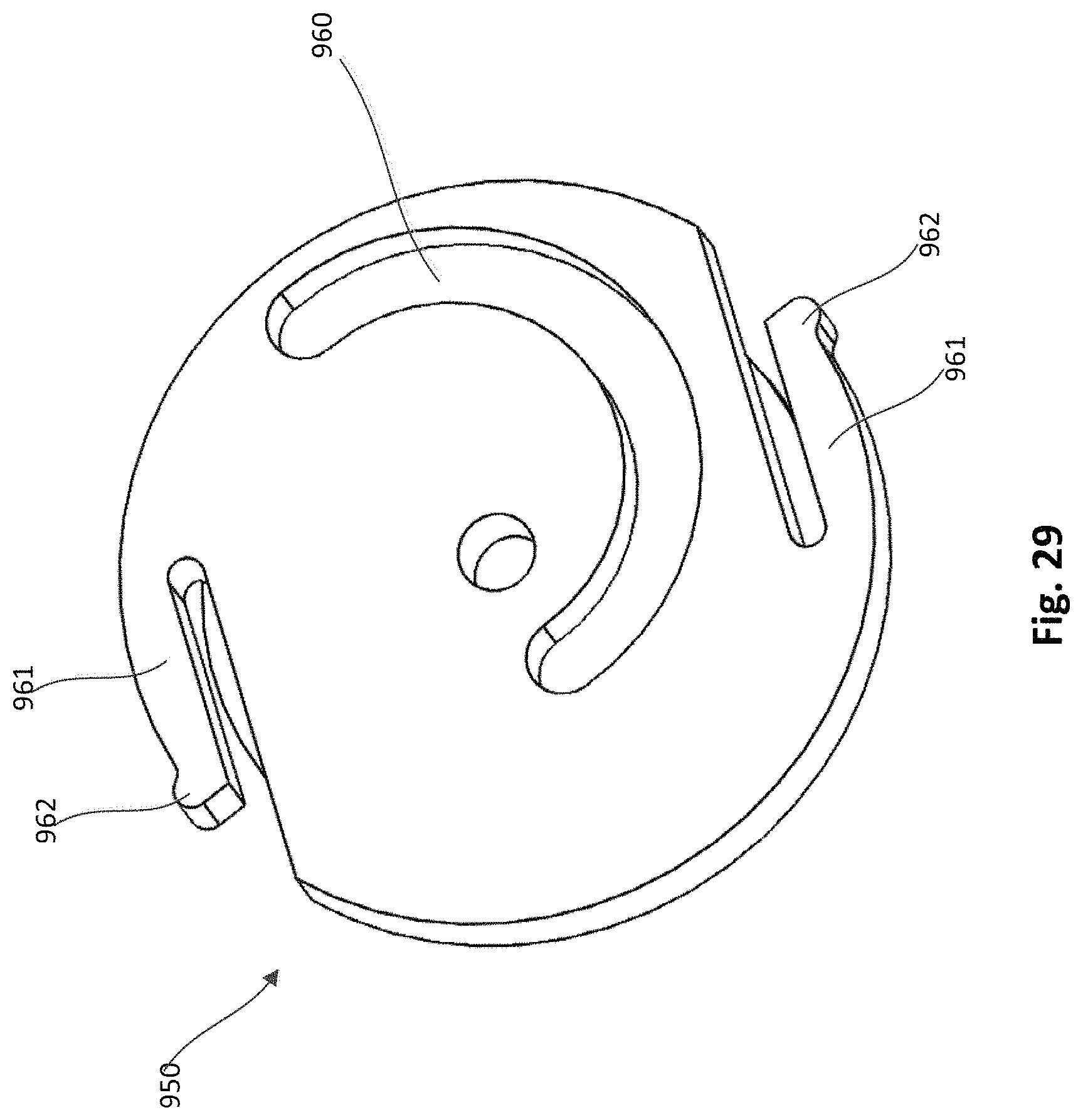
D00030
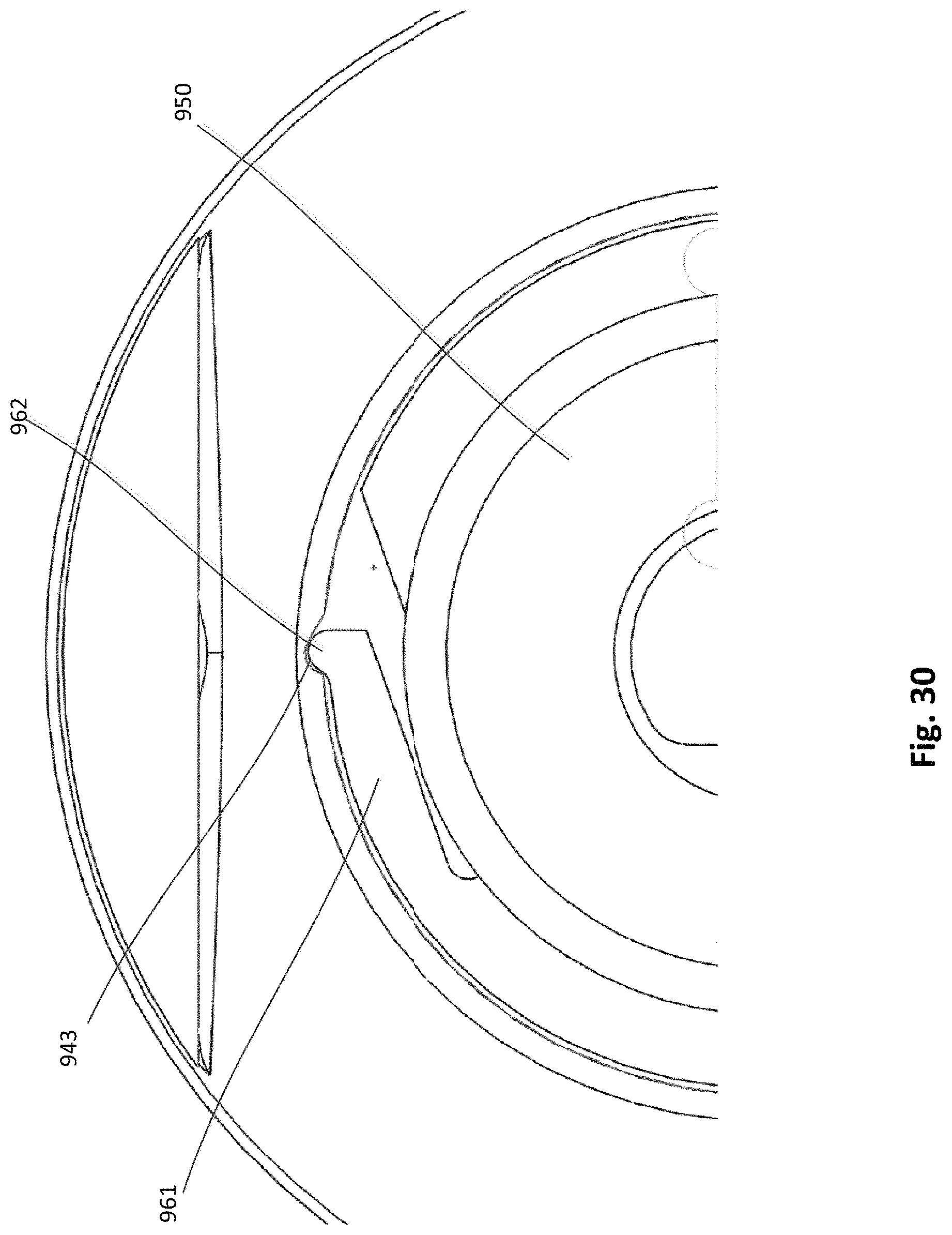
D00031

XML
uspto.report is an independent third-party trademark research tool that is not affiliated, endorsed, or sponsored by the United States Patent and Trademark Office (USPTO) or any other governmental organization. The information provided by uspto.report is based on publicly available data at the time of writing and is intended for informational purposes only.
While we strive to provide accurate and up-to-date information, we do not guarantee the accuracy, completeness, reliability, or suitability of the information displayed on this site. The use of this site is at your own risk. Any reliance you place on such information is therefore strictly at your own risk.
All official trademark data, including owner information, should be verified by visiting the official USPTO website at www.uspto.gov. This site is not intended to replace professional legal advice and should not be used as a substitute for consulting with a legal professional who is knowledgeable about trademark law.