Insertion and removal methods and apparatus for therapeutic devices
de Juan, Jr. , et al.
U.S. patent number 10,603,209 [Application Number 16/004,085] was granted by the patent office on 2020-03-31 for insertion and removal methods and apparatus for therapeutic devices. This patent grant is currently assigned to Forsight Vision4, Inc.. The grantee listed for this patent is ForSight Vision4, Inc.. Invention is credited to Michael S. Barrett, David Batten, Randolph E. Campbell, Eugene de Juan, Jr., Darren Doud, Signe Erickson, Christina Skieller.


View All Diagrams
| United States Patent | 10,603,209 |
| de Juan, Jr. , et al. | March 31, 2020 |
Insertion and removal methods and apparatus for therapeutic devices
Abstract
Described herein is an apparatus to insert an implantable therapeutic device into a patient. The apparatus includes a proximal handle and a distal placement portion coupled to the proximal handle and configured to hold the implantable therapeutic device. The distal placement portion includes a first side having a first engagement structure at a distal end of the first side, the first engagement structure configured to surround at least a first portion of a proximal end region of the implantable therapeutic device. The distal placement portion includes a second, opposite side having a second engagement structure at a distal end of the second side, the second engagement structure configured to surround at least a second, opposite portion of the proximal end region of the implantable therapeutic device.
| Inventors: | de Juan, Jr.; Eugene (Menlo Park, CA), Campbell; Randolph E. (Menlo Park, CA), Erickson; Signe (Menlo Park, CA), Barrett; Michael S. (Menlo Park, CA), Skieller; Christina (Menlo Park, CA), Batten; David (Menlo Park, CA), Doud; Darren (Los Altos, CA) | ||||||||||
|---|---|---|---|---|---|---|---|---|---|---|---|
| Applicant: |
|
||||||||||
| Assignee: | Forsight Vision4, Inc. (South
San Francisco, CA) |
||||||||||
| Family ID: | 47714551 | ||||||||||
| Appl. No.: | 16/004,085 | ||||||||||
| Filed: | June 8, 2018 |
Prior Publication Data
| Document Identifier | Publication Date | |
|---|---|---|
| US 20180289542 A1 | Oct 11, 2018 | |
Related U.S. Patent Documents
| Application Number | Filing Date | Patent Number | Issue Date | ||
|---|---|---|---|---|---|
| 14376331 | 10010448 | ||||
| PCT/US2013/022770 | Jan 23, 2013 | ||||
| 61594961 | Feb 3, 2012 | ||||
| Current U.S. Class: | 1/1 |
| Current CPC Class: | A61K 9/0051 (20130101); A61F 9/0017 (20130101); A61F 9/00772 (20130101); A61M 37/0069 (20130101); A61F 2250/0068 (20130101); A61F 2220/0008 (20130101); A61F 2220/0033 (20130101) |
| Current International Class: | A61F 9/00 (20060101); A61F 9/007 (20060101); A61K 9/00 (20060101); A61M 37/00 (20060101) |
References Cited [Referenced By]
U.S. Patent Documents
| 2564977 | August 1951 | Hu et al. |
| 2585815 | February 1952 | McLintock |
| 3232117 | February 1966 | Gilmont |
| 3416530 | December 1968 | Ness |
| 3618604 | November 1971 | Ness |
| 3641237 | February 1972 | Gould et al. |
| 3828777 | August 1974 | Ness |
| 3902495 | September 1975 | Weiss et al. |
| 3916899 | November 1975 | Theeuwes et al. |
| 3949748 | April 1976 | Malmin |
| 3949750 | April 1976 | Freeman |
| 3961628 | June 1976 | Arnold |
| 3977404 | August 1976 | Theeuwes |
| 3995635 | December 1976 | Higuchi et al. |
| 4008719 | February 1977 | Theeuwes et al. |
| 4014333 | March 1977 | McIntyre |
| 4014334 | March 1977 | Theeuwes et al. |
| 4014335 | March 1977 | Arnold |
| 4034756 | July 1977 | Higuchi et al. |
| 4034758 | July 1977 | Theeuwes |
| 4077407 | March 1978 | Theeuwes et al. |
| 4111201 | September 1978 | Theeuwes |
| 4111203 | September 1978 | Theeuwes |
| 4135514 | January 1979 | Zaffaroni et al. |
| 4160452 | July 1979 | Theeuwes |
| 4200098 | April 1980 | Ayer et al. |
| 4220152 | September 1980 | Dresback |
| 4220153 | September 1980 | Dresback |
| 4256108 | March 1981 | Theeuwes |
| 4298000 | November 1981 | Thill et al. |
| 4300557 | November 1981 | Refojo et al. |
| 4309776 | January 1982 | Berguer |
| 4326525 | April 1982 | Swanson et al. |
| 4327725 | May 1982 | Cortese et al. |
| 4439196 | March 1984 | Higuchi |
| 4475916 | October 1984 | Himmelstein |
| 4484922 | November 1984 | Rosenwald |
| 4519801 | May 1985 | Edgren |
| 4609374 | September 1986 | Ayer |
| 4627850 | December 1986 | Deters et al. |
| 4673405 | June 1987 | Guittard et al. |
| 4693886 | September 1987 | Ayer |
| 4712550 | December 1987 | Sinnett |
| 4737150 | April 1988 | Baeumle et al. |
| 4777049 | October 1988 | Magruder et al. |
| 4781675 | November 1988 | White |
| 4863457 | September 1989 | Lee |
| 4865846 | September 1989 | Kaufman |
| 4883459 | November 1989 | Calderon |
| 4959217 | September 1990 | Sanders et al. |
| 5084021 | January 1992 | Baldwin |
| 5098443 | March 1992 | Parel et al. |
| 5128145 | July 1992 | Edgren et al. |
| 5164188 | November 1992 | Wong |
| 5174999 | December 1992 | Magruder et al. |
| 5178622 | January 1993 | Lehner, II |
| 5277912 | January 1994 | Lowe et al. |
| 5282829 | February 1994 | Hermes |
| 5300114 | April 1994 | Gwon et al. |
| 5322691 | June 1994 | Darougar et al. |
| 5334189 | August 1994 | Wade |
| 5336175 | August 1994 | Mames |
| 5378475 | January 1995 | Smith et al. |
| 5413572 | May 1995 | Wong et al. |
| 5443505 | August 1995 | Wong et al. |
| 5476511 | December 1995 | Gwon et al. |
| 5516522 | May 1996 | Peyman et al. |
| 5554132 | September 1996 | Straits et al. |
| 5562915 | October 1996 | Lowe et al. |
| 5681572 | October 1997 | Seare, Jr. |
| 5702414 | December 1997 | Richter et al. |
| 5766242 | June 1998 | Wong et al. |
| 5770076 | June 1998 | Chu et al. |
| 5773019 | June 1998 | Ashton et al. |
| 5797898 | August 1998 | Santini, Jr. et al. |
| 5807581 | September 1998 | Rosenblatt et al. |
| 5824072 | October 1998 | Wong |
| 5830173 | November 1998 | Avery et al. |
| 5830546 | November 1998 | Ehret et al. |
| 5836935 | November 1998 | Ashton et al. |
| 5868697 | February 1999 | Richter et al. |
| 5902598 | May 1999 | Chen et al. |
| 5916584 | June 1999 | O'Donoghue et al. |
| 5928662 | July 1999 | Phillips |
| 5951512 | September 1999 | Dalton |
| 5972369 | October 1999 | Roorda et al. |
| 5985328 | November 1999 | Chu et al. |
| 6001386 | December 1999 | Ashton et al. |
| 6039712 | March 2000 | Fogarty |
| 6096070 | August 2000 | Ragheb et al. |
| 6123861 | September 2000 | Santini, Jr. et al. |
| 6196993 | March 2001 | Cohan et al. |
| 6303290 | October 2001 | Liu et al. |
| 6331313 | December 2001 | Wong et al. |
| 6375972 | April 2002 | Guo et al. |
| 6395300 | May 2002 | Straub et al. |
| 6413540 | July 2002 | Yaacobi |
| 6416777 | July 2002 | Yaacobi |
| 6420399 | July 2002 | Graff et al. |
| 6472162 | October 2002 | Coelho et al. |
| 6605066 | August 2003 | Gravagna et al. |
| 6663668 | December 2003 | Chaouk et al. |
| 6669950 | December 2003 | Yaacobi |
| 6685940 | February 2004 | Andya et al. |
| 6713081 | March 2004 | Robinson et al. |
| 6719750 | April 2004 | Varner et al. |
| 6740077 | May 2004 | Brandau et al. |
| 6756049 | June 2004 | Brubaker et al. |
| 6756058 | June 2004 | Brubaker et al. |
| 6932983 | August 2005 | Straub et al. |
| 6976982 | December 2005 | Santini, Jr. et al. |
| 6986900 | January 2006 | Yaacobi |
| 7026329 | April 2006 | Crain et al. |
| 7074426 | July 2006 | Kochinke |
| 7077848 | July 2006 | de Juan, Jr. et al. |
| 7090681 | August 2006 | Weber et al. |
| 7094226 | August 2006 | Yaacobi |
| 7117870 | October 2006 | Prescott |
| 7141152 | November 2006 | Le Febre |
| 7181287 | February 2007 | Greenberg |
| 7195774 | March 2007 | Carvalho et al. |
| 7195778 | March 2007 | Fleshner-Barak et al. |
| 7211272 | May 2007 | Renner et al. |
| 7252673 | August 2007 | Lim |
| 7276050 | October 2007 | Franklin |
| 7468065 | December 2008 | Weber et al. |
| 7476510 | January 2009 | Kapur et al. |
| 7585517 | September 2009 | Cooper et al. |
| 7615141 | November 2009 | Schwartz et al. |
| 7621907 | November 2009 | Rodstrom |
| 7625927 | December 2009 | Klimko et al. |
| 7678078 | March 2010 | Peyman et al. |
| 7686016 | March 2010 | Wharton et al. |
| 7709049 | May 2010 | Chappa |
| 7753916 | July 2010 | Weber et al. |
| 7883717 | February 2011 | Varner et al. |
| 7893040 | February 2011 | Loftsson et al. |
| 7906136 | March 2011 | Wong et al. |
| 7909800 | March 2011 | Cazzini |
| 7914442 | March 2011 | Gazdzinski |
| 7939094 | May 2011 | Schwarz et al. |
| 7973068 | July 2011 | Demopulos et al. |
| 8313454 | November 2012 | Yaron et al. |
| 8403941 | March 2013 | Peterson et al. |
| 9987163 | June 2018 | Schaller |
| 10010448 | July 2018 | de Juan, Jr. |
| 2002/0026176 | February 2002 | Varner et al. |
| 2002/0086051 | July 2002 | Viscasillas |
| 2002/0106395 | August 2002 | Brubaker |
| 2002/0110591 | August 2002 | Brubaker et al. |
| 2002/0110592 | August 2002 | Brubaker et al. |
| 2002/0110635 | August 2002 | Brubaker et al. |
| 2002/0116009 | August 2002 | Fraser et al. |
| 2002/0133168 | September 2002 | Smedley et al. |
| 2003/0003129 | January 2003 | Yaacobi |
| 2003/0005945 | January 2003 | Onishi et al. |
| 2003/0014036 | January 2003 | Varner et al. |
| 2003/0118649 | June 2003 | Gao et al. |
| 2003/0119177 | June 2003 | Gruber et al. |
| 2003/0176854 | September 2003 | Rodstrom |
| 2003/0185872 | October 2003 | Kochinke |
| 2003/0212383 | November 2003 | Cote et al. |
| 2003/0235603 | December 2003 | Schwarz et al. |
| 2004/0011651 | January 2004 | Becker et al. |
| 2004/0019325 | January 2004 | Shekalim |
| 2004/0092911 | May 2004 | Yaacobi |
| 2004/0106906 | June 2004 | Yaacobi |
| 2004/0131654 | July 2004 | Yaacobi |
| 2004/0131655 | July 2004 | Yaacobi |
| 2004/0209359 | October 2004 | Yayon et al. |
| 2004/0230183 | November 2004 | Breegi et al. |
| 2004/0238392 | December 2004 | Peterson et al. |
| 2004/0260380 | December 2004 | Marco et al. |
| 2004/0260381 | December 2004 | Marco et al. |
| 2005/0055031 | March 2005 | Lim |
| 2005/0064010 | March 2005 | Cooper et al. |
| 2005/0074497 | April 2005 | Schultz |
| 2005/0112175 | May 2005 | Yaacobi |
| 2005/0112759 | May 2005 | Radisic et al. |
| 2005/0113806 | May 2005 | De Carvalho et al. |
| 2005/0119737 | June 2005 | Bene et al. |
| 2005/0143363 | June 2005 | De Juan et al. |
| 2005/0154399 | July 2005 | Weber et al. |
| 2005/0163711 | July 2005 | Nycz et al. |
| 2005/0181018 | August 2005 | Peyman |
| 2005/0244467 | November 2005 | Nivaggioli et al. |
| 2005/0244469 | November 2005 | Whitcup et al. |
| 2005/0255144 | November 2005 | Schultz |
| 2005/0256499 | November 2005 | Pettis et al. |
| 2005/0271703 | December 2005 | Anderson et al. |
| 2005/0271706 | December 2005 | Anderson et al. |
| 2005/0276837 | December 2005 | Anderson et al. |
| 2005/0277802 | December 2005 | Larsen et al. |
| 2005/0281861 | December 2005 | Hughes et al. |
| 2005/0281863 | December 2005 | Anderson et al. |
| 2005/0287188 | December 2005 | Anderson et al. |
| 2006/0013835 | January 2006 | Anderson et al. |
| 2006/0039952 | February 2006 | Yaacobi |
| 2006/0052754 | March 2006 | Fields |
| 2006/0057277 | March 2006 | Chappa |
| 2006/0073182 | April 2006 | Wong et al. |
| 2006/0104969 | May 2006 | Oray et al. |
| 2006/0110428 | May 2006 | deJuan et al. |
| 2006/0129215 | June 2006 | Helmus et al. |
| 2006/0154981 | July 2006 | Klimko et al. |
| 2006/0172941 | August 2006 | Rastelli et al. |
| 2006/0182783 | August 2006 | Hughes et al. |
| 2006/0200097 | September 2006 | Humayun et al. |
| 2006/0233858 | October 2006 | Tzekov et al. |
| 2006/0246112 | November 2006 | Snyder et al. |
| 2006/0257450 | November 2006 | Mudumba et al. |
| 2006/0258000 | November 2006 | Allen et al. |
| 2006/0258994 | November 2006 | Avery |
| 2006/0276738 | December 2006 | Becker |
| 2007/0020336 | January 2007 | Loftsson et al. |
| 2007/0021357 | January 2007 | Tobia et al. |
| 2007/0026037 | February 2007 | Kloke et al. |
| 2007/0059336 | March 2007 | Hughes et al. |
| 2007/0071756 | March 2007 | Peyman |
| 2007/0072933 | March 2007 | Peyman |
| 2007/0077270 | April 2007 | Wen |
| 2007/0088414 | April 2007 | Campbell et al. |
| 2007/0119450 | May 2007 | Wharton et al. |
| 2007/0128644 | June 2007 | Munenaka |
| 2007/0131610 | June 2007 | Peng et al. |
| 2007/0131611 | June 2007 | Peng et al. |
| 2007/0134305 | June 2007 | Zilberman |
| 2007/0141111 | June 2007 | Suokas et al. |
| 2007/0191863 | August 2007 | De Juan et al. |
| 2007/0197491 | August 2007 | Robin et al. |
| 2007/0203174 | August 2007 | Klimko et al. |
| 2007/0212397 | September 2007 | Roth |
| 2007/0233037 | October 2007 | Gifford et al. |
| 2007/0235331 | October 2007 | Simpson et al. |
| 2007/0243230 | October 2007 | de Juan et al. |
| 2007/0260201 | November 2007 | Prausnitz et al. |
| 2007/0269487 | November 2007 | de Juan et al. |
| 2008/0003219 | January 2008 | Peyman |
| 2008/0004329 | January 2008 | Jamieson et al. |
| 2008/0020045 | January 2008 | Chappa et al. |
| 2008/0038316 | February 2008 | Wong et al. |
| 2008/0057561 | March 2008 | Takahashi et al. |
| 2008/0066739 | March 2008 | LeMahieu et al. |
| 2008/0066741 | March 2008 | LeMahieu et al. |
| 2008/0069854 | March 2008 | Xiao et al. |
| 2008/0089923 | April 2008 | Burkstrand et al. |
| 2008/0097459 | April 2008 | Kammerlander et al. |
| 2008/0111282 | May 2008 | Xie et al. |
| 2008/0124372 | May 2008 | Hossainy et al. |
| 2008/0139674 | June 2008 | Archambeau et al. |
| 2008/0145406 | June 2008 | Asgharian et al. |
| 2008/0146679 | June 2008 | Archambeau et al. |
| 2008/0147021 | June 2008 | Jani |
| 2008/0152694 | June 2008 | Lobl et al. |
| 2008/0154241 | June 2008 | Burkstrand et al. |
| 2008/0161741 | July 2008 | Bene et al. |
| 2008/0167600 | July 2008 | Peyman |
| 2008/0172014 | July 2008 | Whitcup et al. |
| 2008/0181930 | July 2008 | Rodstrom et al. |
| 2008/0200922 | August 2008 | Brown |
| 2008/0207502 | August 2008 | Rastelli et al. |
| 2008/0213611 | September 2008 | Asgari |
| 2008/0216736 | September 2008 | David |
| 2008/0228127 | September 2008 | Burns et al. |
| 2008/0233053 | September 2008 | Gross et al. |
| 2008/0233171 | September 2008 | Whitcup et al. |
| 2008/0233172 | September 2008 | Whitcup et al. |
| 2008/0233173 | September 2008 | Whitcup et al. |
| 2008/0241219 | October 2008 | Whitcup et al. |
| 2008/0241220 | October 2008 | Whitcup et al. |
| 2008/0241221 | October 2008 | Whitcup et al. |
| 2008/0241222 | October 2008 | Whitcup et al. |
| 2008/0241223 | October 2008 | Nivaggioli et al. |
| 2008/0249501 | October 2008 | Yamasaki |
| 2008/0286338 | November 2008 | Rosenthal et al. |
| 2008/0292679 | November 2008 | Lyons et al. |
| 2009/0005864 | January 2009 | Eggleston |
| 2009/0036827 | February 2009 | Cazzini |
| 2009/0043253 | February 2009 | Podaima |
| 2009/0047335 | February 2009 | Rastelli et al. |
| 2009/0082631 | March 2009 | Cronin et al. |
| 2009/0087494 | April 2009 | Kompella et al. |
| 2009/0092654 | April 2009 | de Juan, Jr. et al. |
| 2009/0093752 | April 2009 | Richard et al. |
| 2009/0099626 | April 2009 | de Juan, Jr. et al. |
| 2009/0104243 | April 2009 | Utkhede et al. |
| 2009/0105749 | April 2009 | de Juan et al. |
| 2009/0124997 | May 2009 | Pettis et al. |
| 2009/0214601 | August 2009 | Chappa et al. |
| 2009/0224064 | September 2009 | Brodbeck et al. |
| 2009/0234449 | September 2009 | De Juan, Jr. et al. |
| 2009/0240215 | September 2009 | Humayun et al. |
| 2009/0247458 | October 2009 | Watson et al. |
| 2009/0258069 | October 2009 | Burnier et al. |
| 2009/0263346 | October 2009 | Taft et al. |
| 2009/0263495 | October 2009 | Watson et al. |
| 2009/0274730 | November 2009 | Watson et al. |
| 2009/0274771 | November 2009 | Watson et al. |
| 2009/0280470 | November 2009 | Fare et al. |
| 2009/0281621 | November 2009 | Becker |
| 2009/0324686 | December 2009 | Cooper et al. |
| 2009/0324687 | December 2009 | Cooper et al. |
| 2009/0324688 | December 2009 | Cooper et al. |
| 2009/0324689 | December 2009 | Cooper et al. |
| 2009/0324690 | December 2009 | Cooper et al. |
| 2009/0326448 | December 2009 | Huo et al. |
| 2010/0003333 | January 2010 | Watson et al. |
| 2010/0004189 | January 2010 | Watson et al. |
| 2010/0008997 | January 2010 | Watson et al. |
| 2010/0009008 | January 2010 | Watson et al. |
| 2010/0010452 | January 2010 | Paques et al. |
| 2010/0011888 | January 2010 | Pawliszyn et al. |
| 2010/0015157 | January 2010 | Andya et al. |
| 2010/0016786 | January 2010 | Drews et al. |
| 2010/0021464 | January 2010 | Archambeau et al. |
| 2010/0022943 | January 2010 | Mauch et al. |
| 2010/0022945 | January 2010 | Rodstrom |
| 2010/0023033 | January 2010 | Mauch et al. |
| 2010/0028442 | February 2010 | Archambeau et al. |
| 2010/0028443 | February 2010 | Watson et al. |
| 2010/0030136 | February 2010 | Dacquay et al. |
| 2010/0034870 | February 2010 | Sim et al. |
| 2010/0083963 | April 2010 | Wharton et al. |
| 2010/0100054 | April 2010 | Cormier et al. |
| 2010/0100104 | April 2010 | Yu et al. |
| 2010/0114017 | May 2010 | Lenker et al. |
| 2010/0114309 | May 2010 | de Juan, Jr. et al. |
| 2010/0168535 | July 2010 | Robinson et al. |
| 2010/0174272 | July 2010 | Weiner |
| 2010/0185205 | July 2010 | Novakovic et al. |
| 2010/0197512 | August 2010 | Trinkle et al. |
| 2010/0216702 | August 2010 | Szkudlinski et al. |
| 2010/0221309 | September 2010 | Myers et al. |
| 2010/0241102 | September 2010 | Ma |
| 2010/0255061 | October 2010 | de Juan, Jr. et al. |
| 2010/0256597 | October 2010 | Prausnitz et al. |
| 2010/0266664 | October 2010 | Asgharian et al. |
| 2010/0286121 | November 2010 | Rohrs et al. |
| 2010/0286791 | November 2010 | Goldsmith |
| 2010/0297046 | November 2010 | Schwartz et al. |
| 2010/0297120 | November 2010 | Beliveau et al. |
| 2010/0297193 | November 2010 | Archambeau et al. |
| 2010/0303917 | December 2010 | Watson et al. |
| 2010/0303918 | December 2010 | Watson et al. |
| 2010/0310664 | December 2010 | Watson et al. |
| 2010/0310665 | December 2010 | Watson et al. |
| 2010/0316723 | December 2010 | Watson et al. |
| 2010/0330146 | December 2010 | Chauhan et al. |
| 2011/0009571 | January 2011 | Taft et al. |
| 2011/0014264 | January 2011 | Helmus et al. |
| 2011/0033933 | February 2011 | Gharib et al. |
| 2011/0034448 | February 2011 | Chang et al. |
| 2011/0081384 | April 2011 | Archambeau et al. |
| 2011/0098686 | April 2011 | Varner et al. |
| 2011/0104155 | May 2011 | Rekik |
| 2011/0108025 | May 2011 | Fink et al. |
| 2011/0111006 | May 2011 | Wong et al. |
| 2011/0112188 | May 2011 | Tobia et al. |
| 2011/0117083 | May 2011 | Bais et al. |
| 2011/0125178 | May 2011 | Drews et al. |
| 2011/0159073 | June 2011 | deJuan et al. |
| 2011/0196317 | August 2011 | Lust |
| 2011/0206646 | August 2011 | Alfonso et al. |
| 2012/0029445 | February 2012 | de Juan, Jr. et al. |
| 2012/0029470 | February 2012 | Juan, Jr. et al. |
| 2012/0245505 | September 2012 | Robinson et al. |
| 2013/0218081 | August 2013 | Roth |
| 2013/0274691 | October 2013 | de Juan, Jr. et al. |
| 2013/0274692 | October 2013 | Alster et al. |
| 2014/0031769 | January 2014 | de Juan, Jr. et al. |
| 2014/0073714 | March 2014 | Reich et al. |
| 2014/0114323 | April 2014 | Kudo et al. |
| 2014/0221941 | August 2014 | Erickson et al. |
| 2014/0276901 | September 2014 | Auld |
| 2014/0303637 | October 2014 | Downer et al. |
| 2014/0326249 | November 2014 | Cappiello et al. |
| 2014/0358125 | December 2014 | de Juan, Jr. et al. |
| 2014/0379079 | December 2014 | Ben Nun |
| 2015/0045805 | February 2015 | Kontur et al. |
| 2015/0297402 | October 2015 | de Juan, Jr. et al. |
| 2016/0101046 | April 2016 | Reich et al. |
| 2016/0184134 | June 2016 | Varner et al. |
| 2016/0258855 | September 2016 | Farinas et al. |
| 2016/0302965 | October 2016 | Erickson et al. |
| 2017/0165108 | June 2017 | Bianchi et al. |
| 2017/0165110 | June 2017 | Erickson et al. |
| 2017/0172794 | June 2017 | Varner et al. |
| 2017/0258634 | September 2017 | de Juan, Jr. et al. |
| 2018/0161202 | June 2018 | de Juan, Jr. et al. |
| 2018/0243130 | August 2018 | Doud et al. |
| 2018/0243131 | August 2018 | Erickson et al. |
| 2018/0292403 | October 2018 | de Juan, Jr. et al. |
| 102098993 | Jun 2011 | CN | |||
| 0 228 185 | Nov 1986 | EP | |||
| 0498471 | Aug 1992 | EP | |||
| 0500143 | Aug 1992 | EP | |||
| 0671165 | Sep 1995 | EP | |||
| 0295248 | Apr 1999 | EP | |||
| 0944658 | Jun 2003 | EP | |||
| 1671624 | Jun 2006 | EP | |||
| 1385452 | Sep 2006 | EP | |||
| 1409065 | Jan 2007 | EP | |||
| 1337284 | Dec 2007 | EP | |||
| 1911481 | Apr 2008 | EP | |||
| 1521572 | Mar 2009 | EP | |||
| 2004525695 | Aug 2004 | JP | |||
| 2387462 | Apr 2010 | RU | |||
| WO-88/04573 | Jun 1988 | WO | |||
| WO-90/07545 | Jul 1990 | WO | |||
| WO-95/28984 | Nov 1995 | WO | |||
| WO-97/29850 | Aug 1997 | WO | |||
| WO-98/25982 | Jun 1998 | WO | |||
| WO-00/48660 | Aug 2000 | WO | |||
| WO-01/26714 | Apr 2001 | WO | |||
| WO-01/50943 | Jul 2001 | WO | |||
| WO-03/077972 | Sep 2003 | WO | |||
| WO-03/082188 | Oct 2003 | WO | |||
| WO-2004/000267 | Dec 2003 | WO | |||
| WO-2004/112653 | Dec 2004 | WO | |||
| WO 2005//016401 | Feb 2005 | WO | |||
| WO-2005/027906 | Mar 2005 | WO | |||
| WO-2005/028006 | Mar 2005 | WO | |||
| WO-2005/091922 | Oct 2005 | WO | |||
| WO-2005/107705 | Nov 2005 | WO | |||
| WO-2005/110362 | Nov 2005 | WO | |||
| WO-2005/110436 | Nov 2005 | WO | |||
| WO-2005/110473 | Nov 2005 | WO | |||
| WO-2005/117780 | Dec 2005 | WO | |||
| WO-2006/014484 | Feb 2006 | WO | |||
| WO-2006/015385 | Feb 2006 | WO | |||
| WO-2006/023530 | Mar 2006 | WO | |||
| WO-2006/031358 | Mar 2006 | WO | |||
| WO-2006/031388 | Mar 2006 | WO | |||
| WO-2006/044614 | Apr 2006 | WO | |||
| WO-2006/068838 | Jun 2006 | WO | |||
| WO-2006/071554 | Jul 2006 | WO | |||
| WO-2006/082588 | Aug 2006 | WO | |||
| WO-2006/108054 | Oct 2006 | WO | |||
| WO-2006/125106 | Nov 2006 | WO | |||
| WO-2006/127962 | Nov 2006 | WO | |||
| WO-2006/138609 | Dec 2006 | WO | |||
| WO-2007/012974 | Feb 2007 | WO | |||
| WO-2007/035621 | Mar 2007 | WO | |||
| WO-2007/038453 | Apr 2007 | WO | |||
| WO-2007/044534 | Apr 2007 | WO | |||
| WO-2007/047744 | Apr 2007 | WO | |||
| WO 2007//066339 | Jun 2007 | WO | |||
| WO 2007//084582 | Jul 2007 | WO | |||
| WO-2007/084765 | Jul 2007 | WO | |||
| WO-2007/101204 | Sep 2007 | WO | |||
| WO-2007/117394 | Oct 2007 | WO | |||
| WO-2007/131050 | Nov 2007 | WO | |||
| WO-2007/133761 | Nov 2007 | WO | |||
| WO-2007/133762 | Nov 2007 | WO | |||
| WO-2008/003043 | Jan 2008 | WO | |||
| WO-2008/005240 | Jan 2008 | WO | |||
| WO-2008/011125 | Jan 2008 | WO | |||
| WO-2008/033924 | Mar 2008 | WO | |||
| WO-2008/040062 | Apr 2008 | WO | |||
| WO-2008/045272 | Apr 2008 | WO | |||
| WO-2008/052145 | May 2008 | WO | |||
| WO-2008/060359 | May 2008 | WO | |||
| WO-2008//061043 | May 2008 | WO | |||
| WO-2008/076544 | Jun 2008 | WO | |||
| WO-2008/094989 | Aug 2008 | WO | |||
| WO-2008/115290 | Sep 2008 | WO | |||
| WO-2008/116165 | Sep 2008 | WO | |||
| WO-2008/144340 | Nov 2008 | WO | |||
| WO-2008/144919 | Dec 2008 | WO | |||
| WO-2009/012075 | Jan 2009 | WO | |||
| WO-2009/023615 | Feb 2009 | WO | |||
| WO-2009/046164 | Apr 2009 | WO | |||
| WO-2009/055620 | Apr 2009 | WO | |||
| WO-2009/055671 | Apr 2009 | WO | |||
| WO-2009/055729 | Apr 2009 | WO | |||
| WO-2009/055824 | Apr 2009 | WO | |||
| WO-2009/061607 | May 2009 | WO | |||
| WO-2009/073192 | Jun 2009 | WO | |||
| WO-2009/086112 | Jul 2009 | WO | |||
| WO-2009/089409 | Jul 2009 | WO | |||
| WO-2009/094466 | Jul 2009 | WO | |||
| WO-2009/112878 | Sep 2009 | WO | |||
| WO-2009/117112 | Sep 2009 | WO | |||
| WO-2009/124096 | Oct 2009 | WO | |||
| WO-2009/128932 | Oct 2009 | WO | |||
| WO-2009/134929 | Nov 2009 | WO | |||
| WO-2009/137777 | Nov 2009 | WO | |||
| WO-2010/008424 | Jan 2010 | WO | |||
| WO-2010/021993 | Feb 2010 | WO | |||
| WO-2010/047753 | Apr 2010 | WO | |||
| WO-2010/062628 | Jun 2010 | WO | |||
| WO-2010/066714 | Jun 2010 | WO | |||
| WO-2010//075565 | Jul 2010 | WO | |||
| WO-2010/078063 | Jul 2010 | WO | |||
| WO-2010/080987 | Jul 2010 | WO | |||
| WO-2010/088548 | Aug 2010 | WO | |||
| WO-2010/093945 | Aug 2010 | WO | |||
| WO-2010/095940 | Aug 2010 | WO | |||
| WO-2010/125416 | Nov 2010 | WO | |||
| WO-2010/126908 | Nov 2010 | WO | |||
| WO-2010/135369 | Nov 2010 | WO | |||
| WO-2010//141729 | Dec 2010 | WO | |||
| WO-2010/147661 | Dec 2010 | WO | |||
| WO-2011/008896 | Jan 2011 | WO | |||
| WO-2011/008897 | Jan 2011 | WO | |||
| WO-2011/028850 | Mar 2011 | WO | |||
| WO-2011/034627 | Mar 2011 | WO | |||
| WO-2011/079232 | Jun 2011 | WO | |||
| WO-2012/019136 | Feb 2012 | WO | |||
| WO-2013/082452 | Jun 2013 | WO | |||
| WO-2013/116061 | Aug 2013 | WO | |||
Other References
|
Andrews, "Effect of nonsteroidal anti-inflammatory drugs on LFA-1 and ICAM-1 expression in gastric mucosa," Am J Physiol. Apr. 1994; 266(4 Pt 1):G657-664. cited by applicant . Avery et al., "Intravitreal bevacizumab (Avastin) in the treatment of proliferative diabetic retinopathy," Ophthalmology. Oct. 2006, 113(10):1695-1705.e6. cited by applicant . Bakri et al., "The effect of intravitreal triamcinolone acetonide on intraocular pressure," Ophthalmic Surgery, Lasers and Imaging, Sep./Oct. 2003; 34(5): 386-390. cited by applicant . Bird et al., Transport Phenomena, John Wiley & Sons, Inc., New York, 1960, pp. 196-201. cited by applicant . Block et al., "Solubility and dissolution of triamcinolone acetonide," Journal of Pharmaceutical Sciences, Apr. 1973; 62(4):617-621. cited by applicant . Castro et al., "Effect of COX inhibitors on VEGF-induced retinal vascular leakage and experimental corneal and choroidal neovascularization," Exp Eye Res. Aug. 2004;79(2):275-285. cited by applicant . Chirila et al., "The Vitreous Humor" in Handbook of Biomaterial Properties, eds. Black & Hastings. Chapman & Hall, London, 1998; pp. 125-131. cited by applicant . Cousins et al., "Program # 1251--Targeting Complement Factor 5 in Combination with Vascular Endothelial Growth Factor (VEGF) Inhibition for Neovascular Age Related Macular Degeneration (AMD): Results of a Phase 1 Study," [Presentation Abstract], AMD Clinical Trials Session # 220, May 3, 2010. 2 pages. cited by applicant . Deissler et al., "VEGF-induced effects on proliferation, migration and tight junctions are restored by ranibizumab (Lucentis) in microvascular retinal endothelial cells." Br J Ophthalmol 2008;92:839-843. cited by applicant . Donoso et al., "The role of inflammation in the pathogenesis of age-related macular degeneration," Surv Ophthalmol. Mar.-Apr. 2006;51(2):137-52. cited by applicant . Edelhauser, H et al. "Ophthalmic Drug Delivery Systems for the Treatment of Retinal Diseases Basic Research to Clinical Applications." Investigative Ophthalmology & Visual Science, Nov. 2010. vol. 51, No. 11. pp. 5403-5420. cited by applicant . European Medicine Agency, Scientific Discussion; retrieved from the Internet; <http://www.ema.europa.eu/docs/en_GB/document_library/EPAR_-- _Scientific_Discussion/human/000715/VVC500043550.pdf>, EMEA 2007, 54 pages total. 2007. cited by applicant . Funatsu et al. "Association of vitreous inflammatory factors with diabetic macular edema," Ophthalmology 2009;116:73-79. cited by applicant . Gaudreault et al., "Preclinical Pharmacokinetics of Ranibizumab (rhuFabV2) after a Single Intravitreal Administration," Investigative Ophthalmology and Visual Science. 2005;46:726-733. Retrieved from the Internet: <<http://www.iovs.org/cgi/reprint/46/2/726>>. cited by applicant . Gillies et al., "Intravitreal triamcinolone for refractory diabetic macular edema: two-year results of a double-masked, placebo-controlled, randomized clinical trial," Ophthalmology. Sep. 2006;113(9):1533-1538. cited by applicant . Hastedt & Wright, "Diffusion in porous materials above the percolation threshold," Pharm. Res. Sep. 1990; 7(9):893-901 (1990). cited by applicant . Heier et al, "Ketorolac versus prednisolone versus combination therapy in the treatment of acute pseudophakic cystoid macular edema," Ophthalmology. Nov. 2000;107(11):2034-2038; discussion 2039. cited by applicant . International Search Report dated Jun. 18, 2013, for PCT application No. PCT/US2013/022770. cited by applicant . Jena et al., "A Novel Technique for Surface Area and Particle Size Determination of Components of Fuel Cells and Batteries," Porous Materials, Inc., Dec. 2006, 3 pages total. Downloaded from the Internet: <<http://www.pmiapp.com/publications/docs/A_Novel_technique_for_sur- face_area.pdf>>. cited by applicant . Kang et al., "Inhibitory effects of anti-inflammatory drugs on interleukin-6 bioactivity," Biol Pharm Bull. Jun. 2001;24(6):701-703. cited by applicant . Lopez-Armada et al., "Modulation of cell recruitment by anti-inflammatory agents in antigen-induced arthritis," Ann Rheum Dis Nov. 2002;61(11):1027-1030. cited by applicant . Luncentis, INN-Ranibizumab, "Scientific Discussion," European Medicines Agency; retrieved from the Internet:<http://www.ema.europa.eu/docs/en_GB/document_library/EPAR_- _ Assessment_Report_-_Variation/human/000715/WC500101009.pdf>. Oct. 21, 2010, 32 pages. cited by applicant . Metal Powder Industries Federation, Porous Metal Design Guidebook, 2007, 24 pages total. Downloaded from the Internet: <<http://www.mpif.org/DesignCenter/porous.pdf>>. cited by applicant . Mott Corporation, "Sintered Metal Powder Media," American Filtration & Separation Society 2007, 2 pages total. Downloaded from the Internet:<<http://www.afssociety.org/education/0907oneminute.htm>- ;>. cited by applicant . Navarro, "The Optical Design of the Human Eye: a Critical Review," J Optom, Jan.-Mar. 2009 2(1): 3-18. cited by applicant . Okabe et al., "Intraocular tissue distribution of betamethasone after intrascleral administration using a non-biodegradable sustained drug delivery device," Investigative Ophthalmology and Visual Science. 2003;44:2702-2707. Downloaded from the Internet: <<http://www.iovs.org/cgi/reprint/44/6/2702>>. cited by applicant . Rosenfeld, "The Latest Research: Intravitreal Bevacizumab for Proliferative Diabetic Retinopathy," Review of Ophthalmology's Retina Online, Feb. 2006 2 pages. retrieved from the Internet: http://www.revophth.com/archive/newsletter/0206_retina.htm. cited by applicant . Smith et al., "Spectrophotometric determination of pKa values for fluorescein using activity coefficient corrections," WaterSA 2002; 28(4):395-402. cited by applicant . Soheilian et al., "Pilot Study of Intravitreal Injection of Diclofenac for Treatment of Macular Edema of Various Etiologies," Retina, Mar. 2010; 30(3): 509-515. cited by applicant . Theodossiadis et al., "Intravitreal administration of the anti-tumor necrosis factor agent infliximab for neovascular age-related macular degeneration," Am J Ophthalmol. May 2009;147(5):825-830. cited by applicant . Williams et al., "Treating Diabetic Macular Edema With Ocular NSAIDs," Retinal Physician, Nov. 2007; retrieved from the Internet Nov. 11, 2007. http://www.retinalphysician.com/article.aspx?article=101096>, 5 pages total. cited by applicant. |
Primary Examiner: Price; Nathan R
Assistant Examiner: Bui; Anh
Attorney, Agent or Firm: Mintz Levin Cohn Ferris Glovsky and Popeo, P.C.
Parent Case Text
CROSS-REFERENCE TO RELATED APPLICATION
This application is a continuation of co-pending U.S. application Ser. No. 14/376,331, filed as a national stage application, filed under 35 U.S.C. .sctn. 371, of PCT Application No. PCT/US2013/022770, filed on Jan. 23, 2013, which claims priority to U.S. Provisional Application No. 61/594,961 filed on Feb. 3, 2012, the contents of which are incorporated herein by reference in their entirety for all purposes.
Claims
What is claimed is:
1. An apparatus to insert an implantable therapeutic device into a patient, the apparatus extending along a longitudinal axis from a proximal end of the apparatus to a distal end of the apparatus, the apparatus comprising: a proximal handle; and a distal placement portion coupled to the proximal handle and configured to hold the implantable therapeutic device, the distal placement portion comprising: a first side having a first engagement structure at a distal end of the first side, the first engagement structure being substantially c-shaped and configured to surround at least a first portion of a proximal end region of the implantable therapeutic device; and a second, opposite side having a second engagement structure at a distal end of the second side, the second engagement structure being substantially c-shaped and configured to surround at least a second, opposite portion of the proximal end region of the implantable therapeutic device, wherein each of the first and second engagement structures comprises: a distal-facing surface; a proximal-facing surface opposite the distal-facing surface that extends substantially orthogonal to the longitudinal axis of the apparatus; and an inward-facing protrusion tapering distally towards the distal-facing surface.
2. The apparatus of claim 1, further comprising the implantable therapeutic device, wherein the implantable therapeutic device includes a retention structure at the proximal end region comprising a narrow portion, a shoulder and a proximal extension.
3. The apparatus of claim 2, wherein the inward-facing protrusion and the proximal-facing surface of the first and second engagement structures are shaped and sized to engage a portion of the retention structure.
4. The apparatus of claim 3, wherein each of the inward-facing protrusions is configured to extend into the narrow portion.
5. The apparatus of claim 4, wherein when the inward-facing protrusions extend into the narrow portion, the proximal-facing surface extending substantially orthogonal engages a distal surface of the proximal extension and a distal surface of each protrusion engages the shoulder.
6. The apparatus of claim 2, wherein the distal placement portion further comprises a recess through which a proximal surface of the proximal extension is accessible.
7. The apparatus of claim 6, further comprising at least one guide surface located proximal to the first and second engagement structures and angled obliquely relative to the longitudinal axis from the proximal end towards the distal end of the apparatus.
8. The apparatus of claim 7, wherein the at least one guide surface is configured to support and maintain alignment of a needle extending at an angle oblique to a longitudinal axis of the implantable device prior to penetration of the implantable device by the needle, wherein the longitudinal axis of the implantable device and the longitudinal axis of the apparatus are coaxially aligned.
9. The apparatus of claim 8, wherein the needle includes a connector and wherein the at least one guide surface has a concave shape complimentary to a convex shape of the connector to mate with the connector and maintain alignment of the needle relative to the implantable device.
10. The apparatus of claim 7, wherein the at least one guide surface comprises a plurality of recessed surfaces, each of the plurality of recessed surfaces angled obliquely relative to the longitudinal axis from the proximal end towards the distal end of the apparatus.
11. The apparatus of claim 10, wherein the plurality of recessed surfaces comprises a first proximal guide surface, a first intermediate guide surface and a first distal guide surface on the first side of the distal placement portion and a second proximal guide surface, a second intermediate guide surface and a second distal guide surface on the second side, opposite side of the distal placement portion.
12. The apparatus of claim 10, wherein when the first and second engagement structures are surrounding the proximal end region of the implantable therapeutic device, an upper surface of the implantable therapeutic device remains exposed and external to the apparatus.
13. The apparatus of claim 12, wherein the plurality of recessed surfaces are arranged to provide a visual reference to a user advancing a needle and guide the needle toward the upper surface of the implantable therapeutic device.
14. The apparatus of claim 7, wherein the distal placement portion further comprises a front side and a back side located opposite the front side, wherein the at least one guide surface is located on the front side of the distal placement portion.
15. The apparatus of claim 14, wherein the first engagement structure and the second engagement structure each extends upwards away from the longitudinal axis and away from the at least one guide surface on the front side of the distal placement portion.
16. The apparatus of claim 14, wherein the at least one guide surface on the front side tapers from the proximal end towards the distal end of the apparatus forming a first angle relative to the longitudinal axis, and wherein the back side of the distal placement portion tapers from the proximal end towards the distal end of the apparatus forming a second angle relative to the longitudinal axis, wherein the first angle is different than the second angle.
17. The apparatus of claim 14, wherein the at least one guide surface on the front side has a concave shape and the back side has a substantially convex shape.
18. The apparatus of claim 7, wherein the at least one guide surface has a concave shape to complement a convex shape of a needle connector.
19. The apparatus of claim 1, wherein the proximal handle includes first and second opposing handles extending on opposite sides of the longitudinal axis, wherein the first opposing handle is coupled to a proximal end of the first side and the second opposing handle is coupled to a proximal end of the second side.
20. The apparatus of claim 19, wherein the first and second opposing handles are configured to urge the first side and the second side toward each other to engage the implantable device when the first and second opposing handles move away from the axis and to urge the first side and the second side away from each other to release the implantable device when the first and second opposing handles move toward the axis.
21. The apparatus of claim 19, wherein the first and second opposing handles are configured to urge the first side and the second side toward each other to engage the implantable device when the first and second opposing handles move toward the axis and to urge the first side and the second side away from each other to release the implantable device when the first and second opposing handles move away from the axis.
22. A kit to treat a patient, the kit comprising: an insertion apparatus of claim 1; an implantable therapeutic device; and packaging to contain the insertion apparatus and the implantable therapeutic device.
Description
BACKGROUND
The present disclosure is generally related to methods and apparatus to insert and remove implantable devices. Although specific reference is made to placement in the eye, embodiments as described herein can be used with many implantable devices in locations away from the eye, such as orthopedic, intraluminal and transdermal locations.
Implantable devices can be used to provide a therapeutic agent to one or more locations of a patient. The implantable device may have a reservoir of therapeutic agent, and a structure to retain the implantable device at a desired location of the patient. The implantable device may have a chamber for storing the therapeutic agent, and the agent can be released into the patient to provide a therapeutic benefit. After an amount of time, the amount of fluid released can be less than ideal, and the fluid of the implantable device may be replaced, refilled, or exchanged to provide additional amounts of therapeutic agent to extend the therapy.
The prior methods and apparatus to place an implantable device in the body can be less than ideal in at least some instances. For example, the amount of therapeutic fluid placed in an implanted therapeutic device with injection can be less than ideal in at least some instances. At least some of the prior devices implanted in the eye can be small to decrease interference with vision, and the refill port of such devices can be difficult to fill in at least some instances. The eye can move, and alignment and placement of the implantable device in the eye can be more difficult than would be ideal in at least some instances.
In light of the above, it would be desirable to provide improved treatments for the eye and improved methods and apparatus to place implantable devices in the eye and to place therapeutic fluids in the implantable devices. Ideally, these treatments, methods and apparatus would decrease at least some of the deficiencies of the prior methods and apparatus, and would provide improved placement and removal of devices implanted within the eye.
SUMMARY
Embodiments of the present disclosure provide improved methods and apparatus to insert and remove an implantable device to treat a patient. In many embodiments, the methods and apparatus can provide injection of a therapeutic agent into an implantable device prior to insertion. The implantable device can be manufactured and provided to a clinic without a therapeutic agent, such that the therapeutic agent can be placed in the implantable device in the clinic prior to insertion.
In a first aspect, described herein is an apparatus to insert an implantable therapeutic device into a patient. The apparatus includes a proximal handle, and a distal placement portion coupled to the proximal handle and configured to hold the implantable therapeutic device. The distal placement portion includes a first side having a first engagement structure at a distal end of the first side, the first engagement structure configured to surround at least a first portion of a proximal end region of the implantable therapeutic device. The distal placement portion includes a second, opposite side having a second engagement structure at a distal end of the second side, the second engagement structure configured to surround at least a second, opposite portion of the proximal end region of the implantable therapeutic device.
The apparatus can further include the implantable therapeutic device. The implantable therapeutic device can include a retention structure at the proximal end region having a narrow portion, a shoulder and a proximal extension. Each of the first and second engagement structures can include a protrusion having a surface contour shaped and sized to engage a portion of the retention structure. Each of the protrusions can be configured to extend into the narrow portion. The protrusions can extend into the narrow portion, a proximal surface of each protrusion can engage a distal surface of the proximal extension and a distal surface of each protrusion can engage the shoulder.
The distal placement portion can further include a recess through which a proximal surface of the proximal extension is accessible. The distal placement portion can further include a guide having at least one guide surface configured to support and maintain alignment of a needle extending at an angle oblique to a longitudinal axis of the implantable device prior to penetration of the implantable device by the needle. The needle can include a connector and wherein the at least one guide surface has a shape complimentary to the connector to receive the connector and maintain alignment of the needle relative to the implantable device. The proximal handle can include first and second opposing handles extending on opposite sides of a longitudinal axis. The first opposing handle can be coupled to a proximal end of the first side and the second opposing handle can be coupled to a proximal end of the second side. The first and second opposing handles can be configured to urge the first side and the second side toward each other to engage the implantable device when the first and second opposing handles move away from the axis and to urge the first side and the second side away from each other to release the implantable device when the first and second opposing handles move toward the axis. The first and second opposing handles can be configured to urge the first side and the second side toward each other to engage the implantable device when the first and second opposing handles move toward the axis and to urge the first side and the second side away from each other to release the implantable device when the first and second opposing handles move away from the axis.
In an interrelated aspect, disclosed herein is a method of treating a patient including holding with an insertion apparatus an implantable device having an axis and a penetrable barrier, such that the axis of the implantable device and an axis of the insertion apparatus are concentric. The method includes advancing a needle through the penetrable barrier at an angle oblique to the concentric axes. The method includes injecting a therapeutic fluid through the needle advanced through the penetrable barrier and into a reservoir chamber of the implantable device. The method includes implanting the implantable device into an incision in a tissue of the patient.
The axis of the implantable device and the axis of the insertion apparatus can be concentric when the therapeutic fluid is injected into the reservoir chamber of the implantable device.
In an interrelated aspect disclosed herein is a kit to treat a patient including an insertion apparatus of any of those described herein, an implantable therapeutic device, and packaging to contain the insertion apparatus and the implantable therapeutic device.
Additional aspects are recited in the claims below, and can provide additional summary in accordance with embodiments as described herein. It is contemplated that the embodiments as described herein and recited in the claims may be combined in many ways, and any one or more of the elements recited in the claims can be combined together in accordance with embodiments and teachings as described herein.
BRIEF DESCRIPTION OF THE DRAWINGS
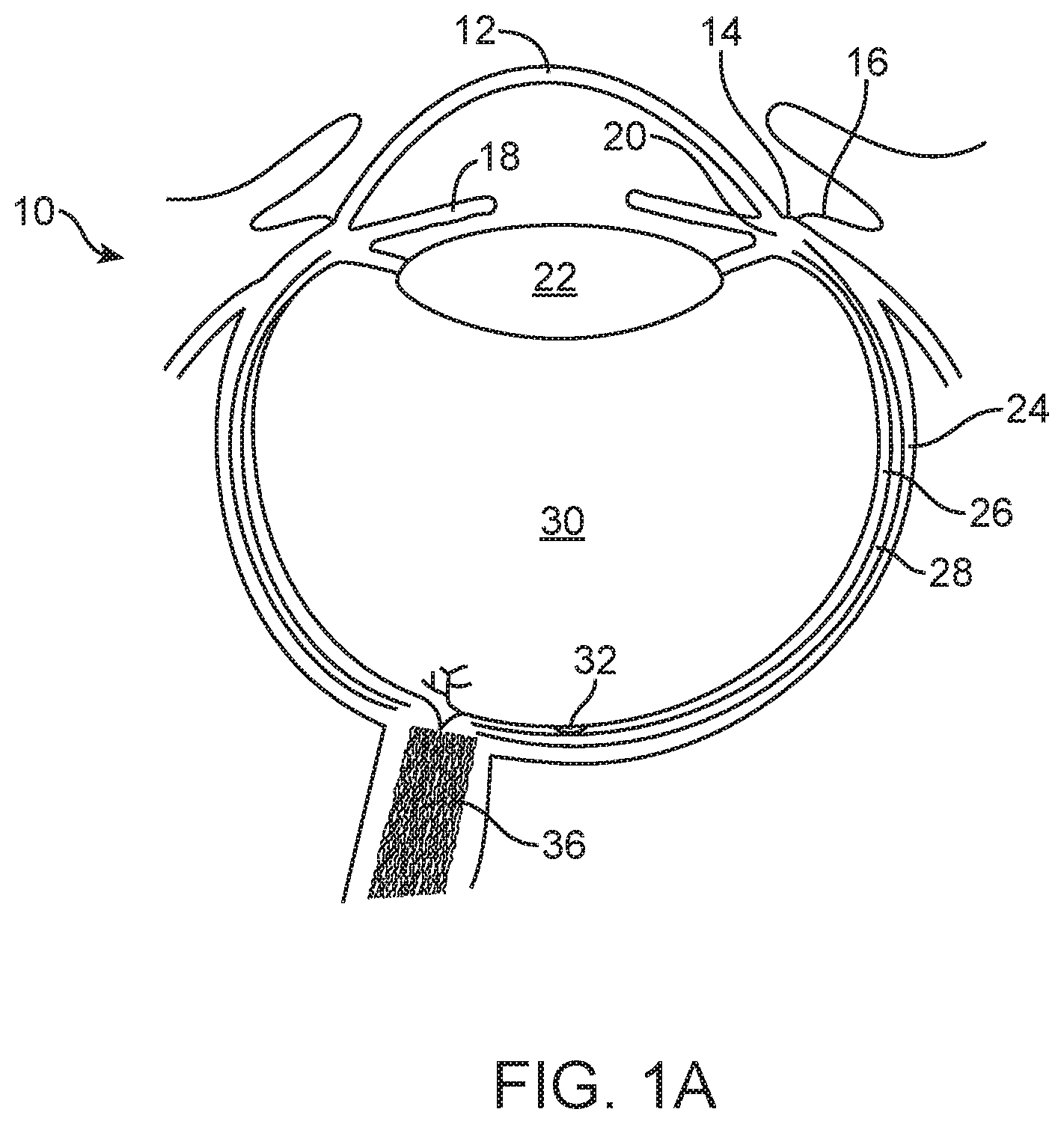
FIG. 1A shows an eye suitable for incorporation of the therapeutic device, in accordance with embodiments;
FIG. 1B shows a therapeutic device implanted under the conjunctiva and extending through the sclera to release a therapeutic agent into vitreous humor of the eye so as to treat the retina of the eye, in accordance with embodiments;
FIG. 1C-1 shows a side cross-sectional view of a therapeutic device including a retention structure having a cross-section sized to fit in an elongate incision, in accordance with embodiments;
FIG. 1C-2 shows an isometric view of the therapeutic device as in FIG. 1C-1;
FIG. 1C-3 shows a top view of the therapeutic device as in FIG. 1C-1;
FIG. 1C-4 shows a side cross sectional view along the short side of the retention structure of the therapeutic device as in FIG. 1C-1;
FIG. 1C-5 shows a side view of the therapeutic device as in FIG. 1C-1 implanted in the sclera;
FIG. 1C-6 shows a cutting tool including a blade having a width corresponding to the perimeter of the barrier and the perimeter of the narrow retention structure portion, in accordance with embodiments;
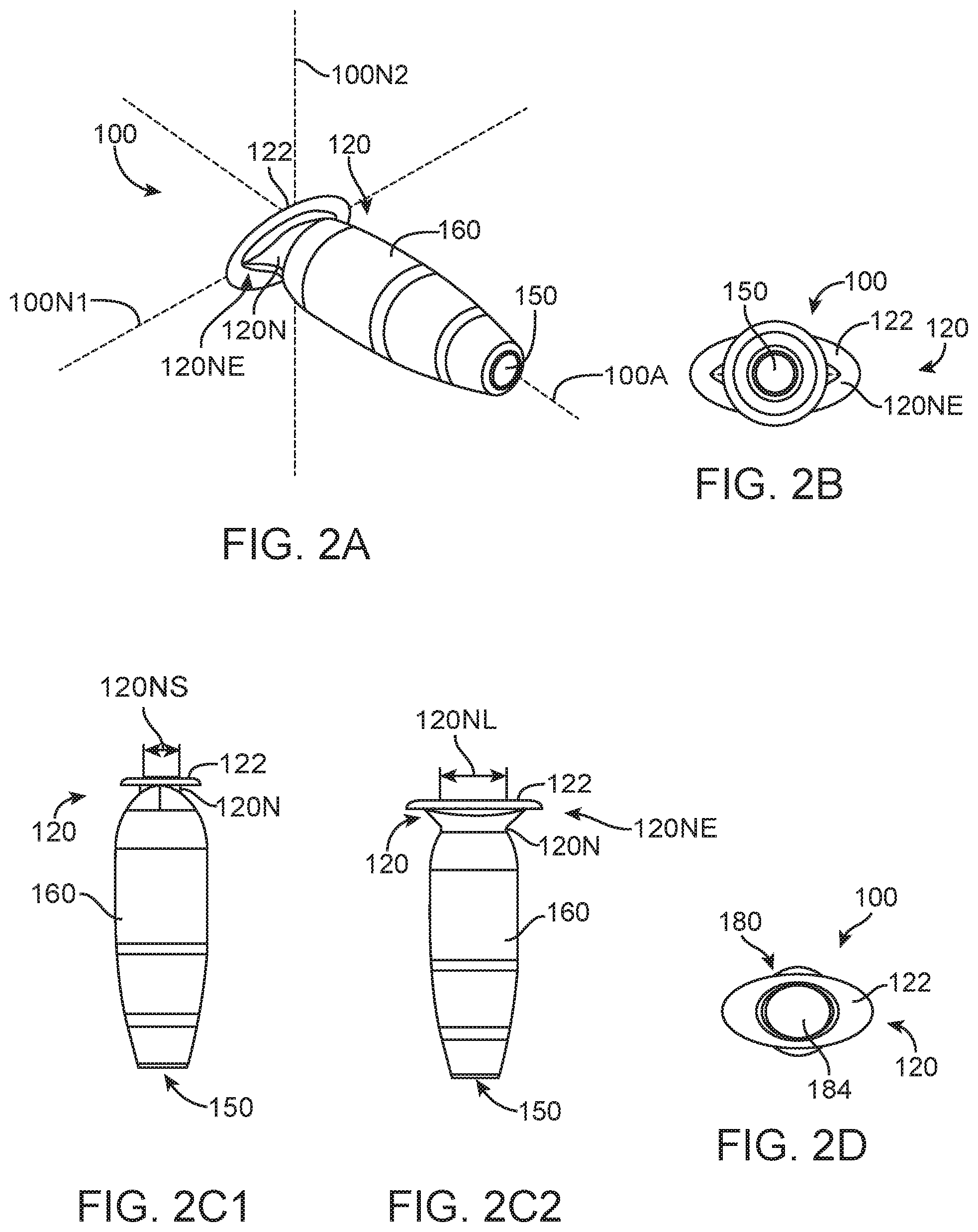
FIG. 2A shows an isometric view of the therapeutic device having a retention structure with an elongate cross-sectional size, in accordance with embodiments;
FIG. 2B shows a distal end view of the therapeutic device as in FIG. 2A;
FIG. 2C1 shows a side view of the short axis of the narrow neck portion of the therapeutic device as in FIG. 2A;
FIG. 2C2 shows a side view of the long axis of the narrow neck portion of the therapeutic device as in FIG. 2A;
FIG. 2D shows a proximal view of the therapeutic device as in FIG. 2A;
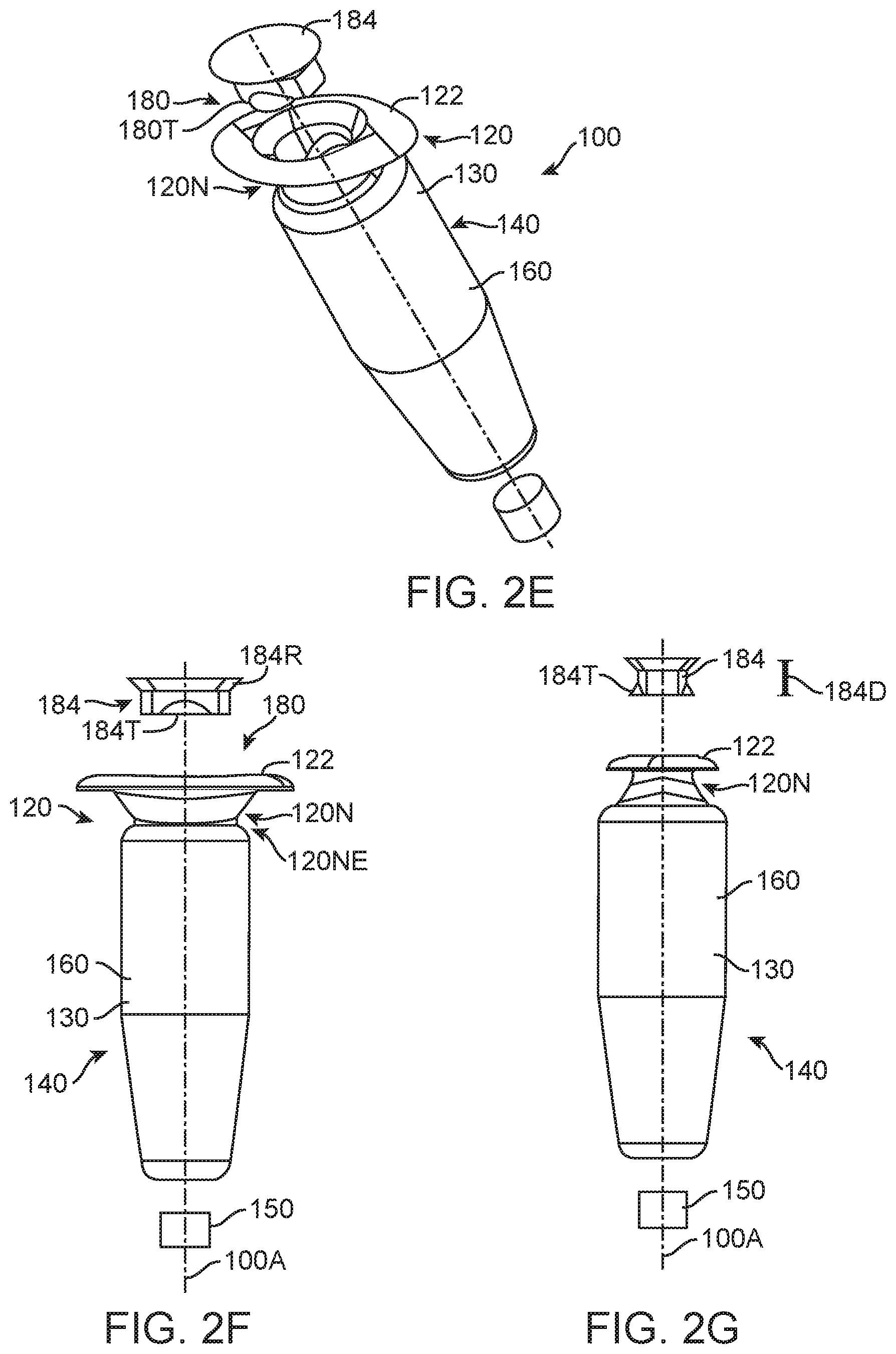
FIGS. 2E to 2G show exploded assembly drawings for the therapeutic device as in FIGS. 2A to 2D;
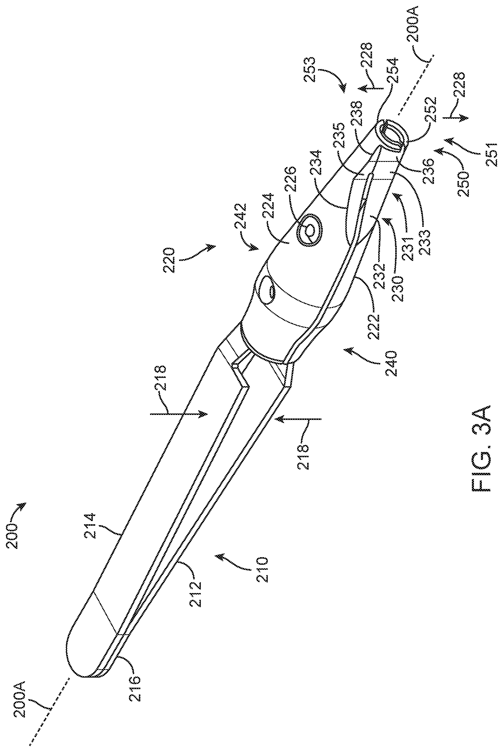
FIG. 3A shows an insertion apparatus in accordance with embodiments;
FIGS. 3B and 3C show front and back views, respectively, of a distal placement portion of the insertion apparatus of FIG. 3A;
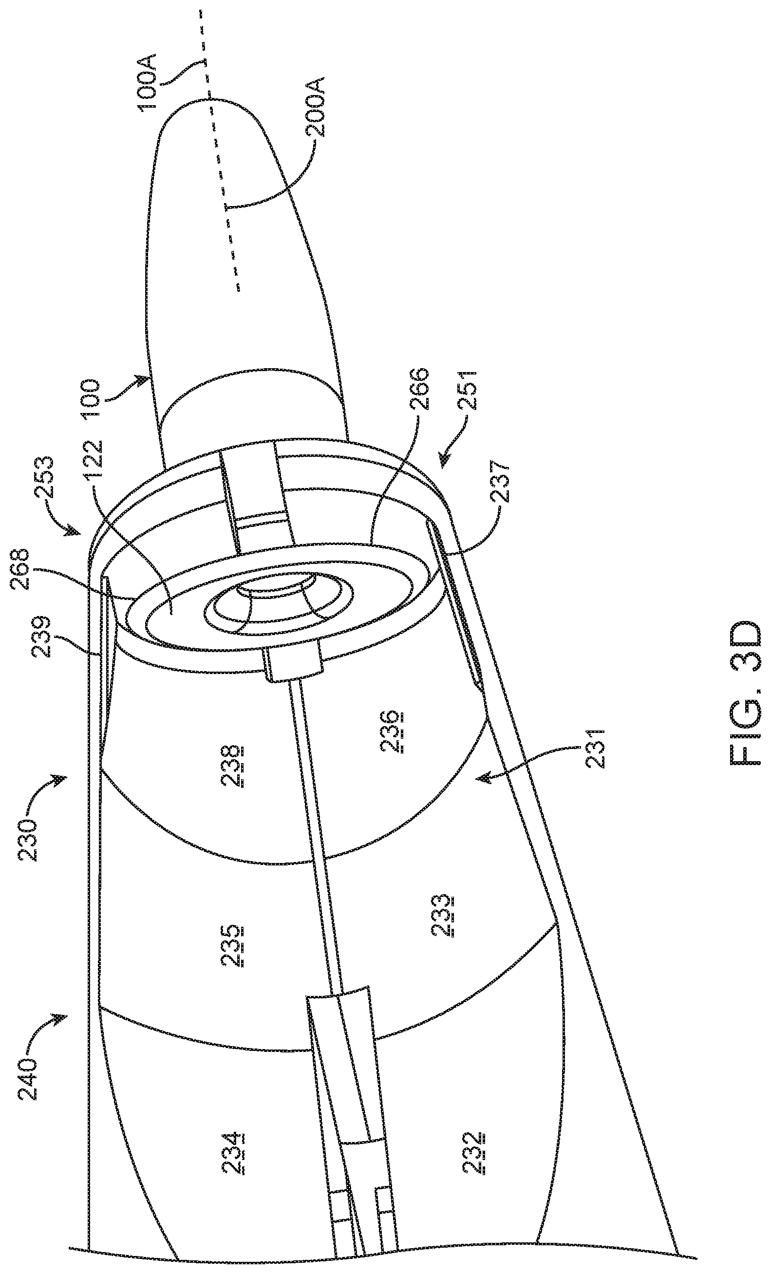
FIGS. 3D and 3E show front and back views, respectively, of the distal placement portion of the insertion apparatus engaging the implantable device;
FIG. 3F shows an injector having a needle advanced toward the implantable device held with the insertion apparatus, in accordance with embodiments;
FIG. 3G shows a side view of the implantable device held with one of the engagement structures and the needle aligned obliquely with the axis of the implantable device, in accordance with embodiments;
FIG. 3H shows the needle inserted obliquely into the implantable device to inject the therapeutic agent, in accordance with embodiments;
FIG. 4A shows a removal tool, in accordance with embodiments;
FIG. 4B shows the removal tool of FIG. 4A aligned with an implantable device, in accordance with embodiments;
FIGS. 4C and 4D show top and bottom views, respectively, of the removal tool of FIGS. 4A and 4B holding the implantable device, in accordance with embodiments;
FIG. 4E shows the removal tool having opposing components, in accordance with embodiments;
FIG. 5A shows a needle inserted into an air-filled implantable device, in accordance with embodiments;
FIG. 5B shows a therapeutic fluid placed in the implantable device of FIG. 5A, in accordance with embodiments;
FIG. 5C shows the therapeutic fluid injected into an implantable device and seeping through a porous structure on the distal end of the device of FIG. 5A, in accordance with embodiments;
FIG. 5D shows the implantable device being placed in the eye, in accordance with embodiments;
FIG. 6A shows a kit having an insertion apparatus, in accordance with embodiments;
FIG. 6B shows a kit having a removal tool, in accordance with embodiments;
DETAILED DESCRIPTION
Embodiments as described herein can be combined in many ways to treat one or more diseases of a patient such as a disease of the eye. The embodiments as described herein are well suited to treat patients with a therapeutic agent for an extended time, such as may be provided with an implantable device. Although specific reference is made to ophthalmic treatment of the eye, the methods and apparatus to place and remove an implantable device can be used with many implantable devices and treatments of one or more of many diseases, such as systemic medication to treat systemic disease, orthopedic treatment to treat orthopedic disorders, or dental treatment, for example. The insertion and removal apparatus and methods as described herein are well suited for use with many drug delivery devices, such as refillable diffusion based devices, and can be exceptionally well suited for diffusion devices having a porous drug release structure configured for extended release in which the porous structure inhibits flow of fluid during exchange. The insertion and removal apparatus and methods as describe herein are well suited for diagnoses and treatment of the eye, for example with diagnosis and treatment of the eye based on the implantable device fluid received with the exchange apparatus with the fluid is injected. The methods and apparatus as described herein are well suited for combination with implantable devices and injector apparatus as described in U.S. patent application Ser. No. 12/696,678, filed on Jan. 29, 2010, entitled "Posterior Segment Drug Delivery", Publication No. 2010/0255061; and U.S. PCT Pat. App. No. PCT/US2011/046812, filed Aug. 5, 2011, entitled "Injector Apparatus and Method for Drug Delivery", the entire disclosures of which are incorporated herein by reference.
As used herein like numerals and/or letters denote like elements in the drawings and text as will be apparent to a person of ordinary skill in the art.
FIG. 1A shows an eye 10 suitable for placement of the therapeutic device. The eye has a cornea 12 and a lens 22 configured to form an image on the retina 26. The cornea can extend to a limbus 14 of the eye, and the limbus can connect to a sclera 24 of the eye. A conjunctiva 16 of the eye can be disposed over the sclera 24. The lens 22 can accommodate to focus on an object seen by the patient. The eye has an iris 18 that may expand and contract in response to light. The eye also includes a choroid 28 disposed the between the sclera 24 and the retina 26. The retina includes the macula 32. The eye includes a pars plana 20, which is an example of a region of the eye suitable for placement and retention, for example anchoring, of the therapeutic device 100 as described herein and shown in 1B. The pars plana region 20 may include sclera 24 and conjunctiva 16 disposed between the retina 26 and cornea 12. The therapeutic device can be positioned so as to extend from the pars plana region 20 into the vitreous humor 30 to release the therapeutic agent. The therapeutic agent can be released into the vitreous humor 30, such that the therapeutic agent arrives at the retina 26 and choroids 28 for therapeutic effect on the macula 32. The vitreous humor of the eye 30 includes a liquid disposed between the lens 22 and the retina 26. The vitreous humor 30 may include convection currents to deliver the therapeutic agent to the macula 32.
FIG. 1B shows a therapeutic device 100 implanted under the conjunctiva 16 and extending through the sclera 24 to release a therapeutic agent 110 into vitreous humor 30 of the eye 10 so as to treat the retina 26 of the eye. The therapeutic device 100 can include a retention structure 120 such as a smooth protrusion configured for placement along the sclera 24 and under the conjunctiva 16, such that the conjunctiva 16 can cover the therapeutic device and protect the therapeutic device 100. When the therapeutic agent 110 is inserted into the device 100, the conjunctiva 16 may be lifted away, incised, or punctured with a needle to access the therapeutic device 100. The eye 10 can include an insertion of the tendon 27 of the superior rectus muscle to couple the sclera 24 of the eye to the superior rectus muscle. The device 100 may be positioned in many locations of the pars plana region 20, for example away from tendon 27 and one or more of posterior to the tendon, posterior to the tendon, under the tendon, or with nasal or temporal placement of the therapeutic device.
While the implant can be positioned in the eye in many ways, work in relation to embodiments suggests that placement in the pars plana region can release therapeutic agent into the vitreous to treat the retina, for example therapeutic agent including an active ingredient composed of large molecules.
Therapeutic agents 110 suitable for use with device 100 include one or more of many therapeutic agents, for example as listed in Table 1A, herein below. The therapeutic agent 110 of device 100 can include one or more of an active ingredient of the therapeutic agent, a formulation of the therapeutic agent, a commercially available formulation of the therapeutic agent, a physician prepared formulation of therapeutic agent, a pharmacist prepared formulation of the therapeutic agent, or a commercially available formulation of therapeutic agent having an excipient. The therapeutic agent may be referred to with generic name or a trade name, for example as shown in Table 1A.
The therapeutic device 100 can be implanted in the eye to treat the eye for as long as is helpful and beneficial to the patient. For example the device can be implanted for at least about 5 years, such as permanently for the life of the patient. Alternatively or in combination, the device can be removed when no longer helpful or beneficial for treatment of the patient.
FIG. 1C-1 shows a side cross-sectional view of therapeutic device 100 including a retention structure 120 having a cross-section sized to fit in an elongate incision. The cross-section sized to fit in the elongate incision can include a narrow portion 120N of retention structure 120 that is sized smaller than the extension 122. The narrow portion 120N (shown in FIG. 1C-2) sized to fit in the elongate incision can include an elongate cross section 120NE sized to fit in the incision. The narrow portion 120N can include a cross-section having a first cross-sectional long distance 120NL, or first dimensional width, and a second cross-sectional short distance 120NS (shown in FIG. 1C-2), or second dimensional width, in which the first cross-sectional distance across is greater than the second cross-sectional distance across such that the narrow portion 120N includes an elongate cross-sectional profile. The first cross-sectional long distance 120NL may extend along a first axis 120N1 and the second cross-sectional short distance 120NS may extend along a second axis 120N2 (shown in FIG. 1C-2).
In many embodiments, the retention structure 120 includes a shoulder 120S extending from the narrow portion 120N to the wall of the reservoir chamber 140, which can include a rigid or expandable annular wall. The shoulder portion 120S can extend from the narrow portion so as to engage the sclera opposite extension 122 and hold the device 100 in the pars plana region. The shoulder 120S of retention structure 120 can include a first shoulder 120S1 on a first side of the retention structure and a second shoulder 120S2 on a second side of the retention structure with axis 120N1 extending therebetween (as shown in 1C-5). Alternatively, the retention structure 120 can include a rotationally symmetric narrow portion 120N having a first side and a second side to fit a dilated incision of the eye, for example, and shoulder 120S can include a rotationally symmetric shoulder extending from the narrow portion 120N to engage a lower portion of the sclera.
The elongate cross section 120NE, shown in FIGS. 1C-2 and 1C-3, of the narrow portion 120N can be sized in many ways to fit the incision. The elongate cross section 120NE having long distance 120NL and short distance 120NS and can include one or more of many shapes such as dilated slit, dilated slot, lentoid, oval, ovoid, or elliptical. The dilated slit shape and dilated slot shape may correspond to the shape sclera tissue assumes when cut and dilated. The lentoid shape may correspond to a biconvex lens shape. The elongate cross-section of the narrow portion can include a first curve along a first axis and a second curve along a second axis different than the first curve.
The porous structure 150 can be located on a distal end portion of the therapeutic device, and the retention structure 120 can be located on a proximal portion of therapeutic device 100, as shown in FIGS. 1C-1, 1C-2, 1C-4, and 1C-5. The porous structure 150 can include one or more of many porous structures such as a sintered material, openings in a non-permeable material, openings having a size and number to release therapeutic agent at an intended rate, a plurality of holes etched in a material, a semi-permeable membrane, or nano-channels, for example.
The reservoir 130 can be configured in many ways, and can include a rigid walled reservoir, for example, or an expandable reservoir. The barrier 160 may define a size of reservoir 130. The barrier 160 and reservoir 130 may each include a circular, an elliptical, oval or other cross-sectional size, for example.
FIG. 1C-2 shows an isometric view of the therapeutic device as in FIG. 1C-1.
FIG. 1C-3 shows a top view of the therapeutic device as in FIG. 1C-1.
FIG. 1C-4 shows a side cross sectional view along the short side of the retention structure of the therapeutic device as in FIG. 1C-1.
FIG. 1C-5 shows a side view of the therapeutic device as in FIG. 1C-1 implanted in the sclera.
FIG. 1C-6 shows a cutting tool 710 including a blade 714 having a width 712 corresponding to perimeter 160P (shown in FIGS. 1C-1, 1C-2, and 1C-3) of the barrier 160 and the perimeter 120NP of the narrow portion. The cutting tool can be sized to the narrow portion 120N so as to seal substantially the incision with the narrow portion when the narrow portion is positioned against the sclera. For example, the width 712 can be about one half of the perimeter 160P of the barrier 160 and about one half of the perimeter 120NP of the narrow portion 120N. For example, the outside diameter of the tube of barrier 160 can be about 3 mm such that the perimeter of 160P is about 6 mm, and the narrow portion perimeter 120NP is about 6 mm. The width 712 of the blade 710 can be about 3 mm such that the incision includes an opening having a perimeter of about 6 mm so as to seal the incision with the narrow portion 120N. Alternatively, perimeter 160P of barrier 160 may have a size slightly larger than the incision and the perimeter of the narrow portion.
The retention structure includes narrow portion 120N having short distance 120NS and long distance 120NL so as to fit in an elongate incision along the pars plana of the eye. The retention structure includes extension 122, and the extension 122 of the retention structure 120 can include a short distance across 122S and a long distance across 122L, aligned with the short distance 120NS and long distance 120NL of the narrow portion 120N of the retention structure 120. The narrow portion 120 can include an indentation 120I sized to receive the sclera, and the indention 120I can include an indentation relative to a maximum dimension across the reservoir chamber 140 and the extension 122 such that the sclera is retained with the indentation 120I. The indentation 120I can include a portion of the extension 122, a portion of the shoulder 120S and a portion of the retention structure extending therebetween, for example.
The therapeutic device 100 can include a non-circular cross-sectional size, and the reservoir chamber 140 can include a rigid walled reservoir having a non-circular, for example elliptical or lentoid cross-sectional size.
FIG. 2A shows an isometric view of the therapeutic device having a retention structure including a narrow portion 120N with an elongate cross-sectional size 120NE.
FIG. 2B shows a distal end view of the therapeutic device as in FIG. 2A.
FIG. 2C1 shows a side view of the short distance 120NS of the narrow portion 120N of the therapeutic device as in FIG. 2A.
FIG. 2C2 shows a side view of the long distance 120NL of the narrow portion 120N of the therapeutic device 100 as in FIG. 2A.
FIG. 2D shows a proximal view of the therapeutic device as in FIG. 2A.
FIGS. 2E to 2G show exploded assembly drawings for the therapeutic device 100 as in FIGS. 2A to 2D. The assembly drawings show isometric and thin side profiles views of the elongate portion 120NE of the narrow portion of the retention structure 120N. The therapeutic device 100 has an elongate axis 100A.
The penetrable barrier 184, for example the septum, can be inserted into the access port 180. The penetrable barrier can include an elastic material sized such that the penetrable barrier can be inserted into the access port 180. The implantable device can include penetrable barrier 184 having a first outer and a second inner surface and a thickness extending a distance 184D between the first surface and the second surface. The penetrable barrier can include one or more elastic materials such as siloxane or rubber. The penetrable barrier can include tabs 184T to retain the penetrable barrier in the access port. The penetrable barrier 184 can include a beveled upper rim 184R sized to seal the access port 180. The access port 180 of the reservoir container 130 can include a beveled upper surface to engage the beveled rim and seal the penetrable barrier against the access port 180 when the tabs 184T engage an inner annular or elongate channel of the access port. The penetrable barrier 184 can include an opaque material, for example a grey material, for example silicone, such that the penetrable barrier can be visualized by the patient and treating physician.
The reservoir container 130 of the device can include a rigid biocompatible material that extends at least from the retention structure to the rigid porous structure, such that the reservoir includes a substantially constant volume when the therapeutic agent is released with the rigid porous structure so as to maintain a stable release rate profile, for example when the patient moves. Alternatively or in combination, the reservoir container 130 can include an optically transmissive material such that the reservoir container 130 can be translucent, for example transparent, such that the chamber of reservoir 140 can be visualized when the device is loaded with therapeutic agent outside the patient prior to implantation, for example when injected with a formulation of therapeutic agent prior to implantation in the physician's office. This visualization of the reservoir 140 can be helpful to ensure that the reservoir 140 is properly filled with therapeutic agent by the treating physician or assistant prior to implantation. The reservoir container can include one or more of many biocompatible materials such as acrylates, polymethylmethacrylate, siloxanes, metals, titanium stainless steel, polycarbonate, polyetheretherketone (PEEK), polyethylene, polyethylene terephthalate (PET), polyimide, polyamide-imide, polypropylene, polysulfone, polyurethane, polyvinylidene fluoride or PTFE. The biocompatible material of the reservoir container can include an optically transmissive material such as one or more of acrylate, polyacrylate, methlymethacraylate, polymethlymethacrylate (PMMA), polyacarbonate or siloxane. The reservoir container 130 can be machined from a piece of material, or injection molded, so as to form the retention structure 120 including extension 122 and the elongate narrow portion 120NE. The extension 122 can include a translucent material such that the physician can visualize tissue under the flange to assess the patient and to decrease appearance of the device 100 when implanted. The reservoir container 130 can include a channel extending along axis 100A from the access port 180 to porous structure 150, such that formulation injected into device 100 can be released in accordance with the volume of the reservoir and release rate of the porous structure 150 as described herein. The porous structure 150 can be affixed to the distal end of therapeutic device 100, for example with glue. Alternatively or in combination, the distal end of the reservoir container 130 can include an inner diameter sized to receive the porous structure 150, and the reservoir container 130 can include a stop to position the porous structure 150 at a predetermined location on the distal end so as to define a predetermined size of reservoir 140.
FIG. 3A shows an insertion apparatus 200. The insertion apparatus includes a proximal handle 210 and a distal placement portion 220. The handle 210 includes a first extension 212 and a second extension 214. A proximal end portion 216 couples the first extension 212 to the second extension 214. The insertion apparatus 200 includes an axis 200A extending along an elongate dimension of the insertion apparatus 200.
The proximal handle 210 includes structures to manipulate the distal placement portion 220. The first extension 212 and second extension 214 may be combined in many ways to manipulate the distal placement portion 220. The first extension 212 and the second extension 214 may extend to opposing sides of the distal portion 220. The first extension 212 and the second extension 214 and can include a resilient spring having the extensions coupled together at the distal end portion 216, for example with a weld on the distal end portion 216. The user can urge the first extension 212 toward the second extension 214 against the resilient extensions as shown with arrows 218, and the user can release the extensions, such that the spring forces urges the first extension 212 away from the second extension 214 opposite arrows 218.
The distal placement portion 220 includes structures to hold and place the implantable device 100. The distal placement portion 220 includes a guide 230 and an engagement structure 250. The engagement structure 250 is configured to engage the implantable device 100, and the guide 230 is configured to facilitate alignment and access to the implantable device 100 with a needle or other filling device so as to place therapeutic agent inside the implantable device 100. The guide 230 can be located on a front 240 of the placement portion 220, and can be readily viewed by a user. The front 240 is located opposite a back 242. The guide 230 located on the front 240 allows viewing of the recess 231 when the needle is advanced into the recess, as will be described in more detail below. The distal placement portion 220 includes a first side 222 and a second side 224 located opposite the first side 222. The first side 222 is movable opposite the second side 224 so as to engage the implantable device 100 with the first side 222 and the second side 224.
The engagement structure 250 can be configured to contact the implantable device in many ways, and can include a first engagement structure 251 on first side 222 and a second engagement structure 253 on the second side 224 opposite the first engagement structure. The first engagement structure 251 on first side 222 includes a first projection 252 extending at least partially around axis 200A. The second engagement structure 252 on second side 224 includes a second projection 254 extending at least partially around axis 200A opposite the first projection 252. The first and second projections 252, 254 may extend circumferentially and axially in relation to axis 100.
The guide 230 of the distal placement portion 220 can be configured in many ways to guide a needle toward recess 231 when the insertion apparatus holds the implantable device with the engagement structure 250. The guide 230 can include the first side 222 and the second side 224. The guide 230 can include a plurality of recessed surfaces that allow a short needle to be used to place the therapeutic fluid including therapeutic agent 110 in the implantable device. The guide 230 can include a first proximal guide surface 232 and first intermediate guide surface 233, and a first distal guide surface 236 on the first side 222. The guide 230 can include a second proximal guide surface 234 and second intermediate guide surface 235, and a second distal guide surface 238 on the second side 224. The guide surfaces are arranged to provide a visual reference to a user advancing a needle and also provide a surface to support the needle connector and maintain alignment of the needle when placed.
The first extension 212 and the second extension 214 can be coupled to the distal placement portion 220 in many ways. The extensions can be coupled to the distal portion so that pressing the extensions together separates the first engagement structure 251 of the first side 222 from the second engagement structure 253 of the second side 224 as shown with arrows 228, for example (see FIGS. 3A and 3B). The extension 212 and the extension 214 can include springs such that the first engagement structure 251 is urged toward the second engagement structure 253 when the user gently grasps the extensions without urging the extensions inward. The first extension 212 on the first side 222 can extend transverse to axis 200A and affix to second side 224, and the second extension 214 can extend transverse to axis 200A and affix to first side 222, for example. Alternatively, the first extension 212 and the second extension 214 can be coupled to the distal placement portion 220 such that urging the extensions toward each other urges the first engagement structure 251 toward the second engagement structure 253 so as to hold the implantable device 100, and such that releasing the extensions separates the first engagement structure 251 from the second engagement structure 253 with resilient spring force so as to release the implantable device 100. The first extension 212 can extend and affix to first side 222 of the distal placement portion 220, and the second extension 214 can extend and affix to second side 224, for example.
The first extension 212 and the second extension 214 can be affixed to the distal placement portion 220 in many ways. Fasteners 226 can be used to couple the extensions to the distal placement portion, for example.
FIGS. 3B and 3C show front and back views, respectively, of a distal placement portion of the insertion apparatus of FIG. 3A. The first engagement structure 251 includes a protrusion 262, and the second engagement structure 253 includes a protrusion 264. The protrusion 262 and the protrusion 264 are sized to fit in one or more recesses, such as the narrow region, of the implantable device to retain the implantable device. The protrusion 262 includes a distal surface 256 to engage the shoulder of the implantable device, and the opposing protrusion 264 includes a distal surface 258 to engage the implantable device on an opposite side. The projection 252 can include a flange 237, and the projection 254 can include a support flange 239.
The first extension 212 can be affixed to the second side 224 of the distal placement portion 220, and the second extension 214 can be affixed to the first side 222 of the distal placement portion 220.
FIG. 3D and FIG. 3E show the implantable device 100 and the distal placement portion 220 of the insertion apparatus 200 (FIG. 3A), the retention structure 120 (FIG. 2E) of the implantable device 100 can be aligned with the engagement structure 250 (FIG. 3A). The retention structure 120 includes a narrow portion 120N (FIG. 2E) dimensioned to receive the protrusion 262 and the protrusion 264 (FIG. 3C) to hold the implantable device. The protrusion 262 and the protrusion 264 (FIG. 3C) can be shaped in many ways to engage the narrow portion 120N (FIG. 2E), and can include lentoid, oval, elliptical or circular structures. In many embodiments, the protrusion 262 and the protrusion 264 (FIG. 3C) include a structure similar to the shape profile or outer contour of the narrow portion 120N (FIG. 2E), and can include circular structures when the narrow portion 120N (FIG. 2E) includes a circular cross section, for example. In many embodiments, the narrow portion 120N (FIG. 2E) includes one or more an oval, elliptical or lentoid geometry, and the protrusion 262 and the protrusion 264 (FIG. 3C) include a corresponding geometry, for example.
The first protrusion 262 on first engagement structure 251 (FIG. 3C) can include a proximal surface 266 to engage a distal surface of the extension 122 of the retention structure 120 (FIG. 3D), and the second protrusion 264 on the second engagement structure 253 can include a proximal surface 268 to engage the distal surface of the extension 122 of the retention structure 120, for example (FIG. 3C and FIG. 3D). The first engagement structure 251 can be urged toward the second engagement structure 253 to slide the first protrusion 262 and the second protrusion 264 (FIG. 3C) into the indentation 120N of the retention structure 120 (FIG. 2E).
FIGS. 3D and 3E show front and back views, respectively, of the distal placement portion 220 of the insertion apparatus 200 (FIG. 3A) engaging the implantable device 100. The first engagement structure 251 and the second engagement structure 253 extend substantially around the retention structure 120 (FIG. 2E) to hold the implantable device 100. FIG. 3D shows the extension 122 of the retention structure, as the rest of the retention structure is obscured from view by the first and second engagement structures, 251 and 253, respectively. FIG. 3E shows the shoulder 120S of the retention structure, as the rest of the retention structure is obscured from view by the first and second engagement structures, 251 and 253, respectively. The implantable device 100 is held such that the axis 100A of the implantable device is aligned substantially with the axis 200A of the insertion apparatus. The implantable device 100 can be held with the axis 100A substantially concentric with the axis 200A of the insertion apparatus 200, for example. FIG. 3D also shows elements of the distal placement portion 220 shown in FIG. 3B and described herein above, such as the recess 231; the guide 230 that may have first and second proximal guide surfaces (232 and 234, respectively), first and second intermediate guide surfaces (233 and 235, respectively), and first and second distal guide surfaces (236 and 238, respectively); and the support flanges 239 and 237. FIG. 3E also shows the distal surfaces 256 and 258 of the engagement structures 251 and 253, respectively.
FIG. 3F shows an injector 300 having a needle 310 advanced toward the implantable device 100 held by the insertion apparatus 200. The injector 300 can include needle 310 and a syringe 360, for example. The needle 310 can be coupled to the syringe 360 with a connector 350. The connector 350 can include extensions 352 to couple the needle to the syringe 360. The syringe 360 and the needle 310 may extend substantially along an axis 300A. The needle 310 can include a housing 340. The housing 340 can include a plurality of structures to couple to or engage with the guide 230, such that the needle 310 can be advanced along axis 300A toward the proximal end of the implantable device 100. The plurality of structures of the housing 340 can include a first structure 320, a second structure 330, for example. The guide 230 and housing 340 can be configured to align the axis 300A of the needle 310 oblique to the axis 100A of the implantable device and the axis 200A of the insertion apparatus when the needle 310 advances toward the penetrable barrier of the implantable device 100. FIG. 3F also shows the recess 231, the second projection 254, and the proximal surface 268 of the engagement structure.
FIG. 3G shows a side view of the implantable device 100 held with one of the engagement structures 251 and the needle 310 aligned obliquely with the axis 100A of the implantable device. The protrusion 262 extends substantially into the narrow portion 120N of retention structure 120 (FIG. 2E). The distal surface 256 of the protrusion 262 engages the shoulder 120S. The proximal surface 266 of the protrusion 262 of engages the distal surface of the extension 122 of the retention structure 120. The shoulder 120S can include a first shoulder 120S1 and a second shoulder 120S2 on first and second sides, respectively, of the retention structure 120 as described herein, for example.
In many embodiments, the second engagement structure 253 includes structure similar to the first engagement structure 251 as described herein.
FIG. 3H shows the needle inserted obliquely into the implantable device 100, for example to inject the therapeutic agent. The implantable device can include penetrable barrier 184 (FIG. 2E) having a first outer surface facing the syringe 360 and a second inner surface and a thickness extending between the first surface and the second surface. The needle 310 can pass through the penetrable barrier 184 at an angle away from perpendicular to the surfaces such that the needle 310 extends within the penetrable barrier 184 a distance greater than the thickness 184D (shown in FIG. 2G). The housing 340 can be aligned substantially with the guide 230 so as to support the housing 340 with the guide 230 when the needle 310 extends through the penetrable barrier 184. For example the surface 232 can be aligned substantially with the outer surface of the casing 340. A distal portion of the surface 233 can be aligned substantially with a distal portion of the structure 330. A distal portion 322 of the structure 320 can engage the proximal surface 266 so as to limit penetration of the needle 310 into the implantable device, for example.
FIG. 4A shows a removal tool 400. The removal tool 400 can include a handle 410 and an engagement structure 450. The engagement structure 450 can include a first engagement structure 451 and a second engagement structure 453. The first engagement structure 451 can be located on a first side of axis 400A, and the second engagement structure 453 can be located on a second side of axis 400A opposite the first engagement structure 451. The handle 410 can be configured in many ways and can include a first extension 412 and a second extension 414. The first extension 412 and the second extension 414 may extend along opposite sides of an axis 400A. The extension 412 can be connected to the extension 414 at a proximal end 416. The extensions can be connected in many ways, for example with weld. The extension 412 and the extension 414 can include resilient material such that each extension includes a component of a spring. The first extension 412 can be urged toward the second extension 414 as shown with arrows 418, such that the first engagement structure 451 is urged toward the second engagement structure 453 as shown with arrows 428, for example. Alternatively, the engagement structures can be connected to the extensions in many alternative ways as described herein, for example.
FIG. 4B shows the removal tool of FIG. 4A aligned with an implantable device 100. The conjunctiva and a Tenon's of the eye can be removed so as to expose device 100, which can be aligned with the removal tool 400 as shown.
The first engagement structure 451 includes a first projection 452 and a second projection 456 which extend toward axis 400A, so as to define a channel 482 sized to receive the indentation 120N of the implantable device 100. The first projection 452 includes a tapered portion 462 extending to a leading edge 472. The second projection 456 includes a tapered portion 466 extending to a leading edge 476. The leading edges are configured to slide under the extension 122 of the retention structure 120.
The second engagement structure 453 includes a first projection 454 and a second projection 458 which extend toward axis 400A, so as to define a channel 484 sized to receive the indentation 120N of the implantable device 100. The first projection 454 includes a tapered portion 464 extending to a leading edge 474. The second projection 458 includes a tapered portion 468 extending to a leading edge 478. The leading edges are configured to slide under the extension 122 of the retention structure 120 opposite the leading edges of the engagement structure 451.
The axis 400A of the removal apparatus 400 can be aligned with the axis 100A of the implantable device 100 when the engagement structures are urged toward each other.
FIGS. 4C and 4D show top and bottom views, respectively, of the removal tool 400 of FIGS. 4A and 4B holding the implantable device 100. The leading edge 472, adjacent to tapered portion 462, engages the leading edge 474, adjacent to tapered portion 464, so as to define a first stop, and the leading edge 476, adjacent to tapered portion 466, engages the leading edge 478, adjacent to tapered portion 468, so as to define a second stop. The channel 482 and the channel 484 are sized to provide a gap extending around the narrow portion 120N when leading edges of engagement structure 451 engage the leading edges of the engagement structure 453. The removal tool engages extension 122 of the retention structure 120 (FIG. 2E) with the proximal surfaces of projection 452, projection 454, projection 456 and projection 458, and the gap provides clearance to inhibit pinching of the narrow portion 120N of the retention structure. FIG. 4D also shows a shoulder 120S1 of the retention structure 120 in relation to the engagement structures 451 and 453.
The retention structure 120 and the narrow portion 120N (FIG. 2A-G) of the retention structure can be configured in many ways as described herein. In many embodiments, the long distance of the retention structure 120N is aligned such that the projections slide under the extension 122 in alignment with the long distance of the narrow portion 120N. Alternatively, the short distance of the retention structure 120N may be aligned such that the projections slide under the extension 122 in alignment with the short distance of the narrow portion 120N. A person of ordinary skill in the art will recognize many variations based on the teachings and embodiments described herein, and the narrow portion 120N can include a substantially circular cross-sectional area, for example.
The removal tool 400 can be fabricated in many ways. For example, removal tool 400 can include a unitary structure. Alternatively, the extension and engagement structure of each side can include a unitary structure fabricated from a single piece of material, and the two unitary structures can be joined together at the proximal end 416 for example with a weld as described herein, for example.
FIG. 4E shows the removal tool 400 having opposing components 490 holding a device with an alignment axis, 100A. The opposing components 490 can include a first component 492 having first engagement structure 451, and a second component 494 having second engagement structure 453. The first component 492 can be affixed to first extension 412 and the second component 494 can be affixed to the second extension 414, for example.
FIGS. 5A to 5D show a method 500 of placing therapeutic device 100 in an eye 10.
FIG. 5A shows a step 510. At step 510, an injector apparatus 300 having a needle is inserted into the implantable device 100 containing air 70. The device 100 is held by an insertion apparatus 200, and the injector apparatus 300 fits into the guide 230 of the insertion apparatus 200. The insertion of the needle into the device 100 can be viewed through a binocular operating microscope 505. The needle can be inserted with the guide 230 into the recess as described herein when viewed through microscope 505.
FIG. 5B shows a therapeutic fluid 119 having therapeutic agent 110 placed in the implantable device 100 at a step 520. The therapeutic fluid can include a flowable material, for example a solution. The wall of the reservoir chamber of the therapeutic device 100 can include a substantially transparent material so that the flow of the fluid 119 toward the porous structure 150 on the distal end can be visualized.
FIG. 5C shows the therapeutic fluid injected such that some therapeutic fluid flows through a porous structure on the distal end of the implantable device of FIG. 5A at a step 530. The therapeutic fluid 119, containing the therapeutic agent 110, can be injected through the porous structure 150 so as to accumulate on the distal end of device 100. The accumulation of fluid 119 on the distal end can indicate to the physician that the reservoir chamber of device 100 has been filled. The physician can inspect the device 100 for air bubbles, for example, so as to ensure the device has been filled properly.
FIG. 5D shows the implantable device 100 being placed in the eye 10 with insertion apparatus 200 at a step 540. The device 100 filled with therapeutic agent 110 can be implanted at the pars plana region 20 as described herein. The conjunctiva can be removed from the sclera, and the device 100 placed in the eye. The conjunctiva can be placed over device 100 and the conjunctiva sutured in place. Device 100 is configured such that a layer of Tenon's capsule can grow over the extension 122 of device 100 to retain device 100.
FIG. 6A shows a kit 600 having an insertion apparatus 200 and sterile packaging 610. The kit 600 can include the insertion apparatus 200 and the device 100 placed in the packaging. The retention structure of the device 100 can be mounted in the engagement structure of the apparatus 200 as described herein when provided in the kit. Alternatively, the device 100 can be within sterile packaging 610 separated from apparatus 200, and the device 100 engaged with apparatus 200 after the sterile kit has been opened, for example. The kit 600 can include the injector apparatus 300.
FIG. 6B shows a kit 650 including a removal tool 400. The kit 650 can include sterile packaging 660 to protect removal apparatus 400.
While the exemplary embodiments have been described in some detail, by way of example and for clarity of understanding, those of skill in the art will recognize that a variety of modifications, adaptations, and changes may be employed. Hence, the scope of the present disclosure shall be limited solely by the appended claims.
TABLE-US-00001 TABLE 1A Therapeutic Agent List Molecular Generic Name Brands (Companies) Category Indication Weight 2-Methoxyestradiol (Paloma Angiogenesis inhibitors AMD analogs Pharmaceuticals) 3-aminothalidomide 13-cis retinoic acid Accutane TM (Roche Pharmaceuticals) A0003 (Aqumen A0003 AMD BioPharmaceuticals) A5b1 integrin (Jerini Ophthalmic); Inhibitors of a5b1 AMD inhibitor (Ophthotech) integrin Abarelix Plenaxis .TM. (Praecis Anti-Testosterone For palliative treatment 37731 Pharmaceuticals) Agents; Antineoplastic of advanced prostate Agents cancer. Abatacept Orencia .TM. (Bristol- Antirheumatic Agents For the second line 37697 Myers Squibb) reduction of the signs and symptoms of moderate-to-severe active rheumatoid arthritis, inducing major clinical response, slowing the progression of structural damage, and improving physical function in adult patients who have Abciximab ReoPro .TM.; ReoPro .TM. Anticoagulants; For treatment of 42632 (Centocor) Antiplatelet Agents myocardial infarction, adjunct to percutaneous coronary intervention, unstable angina ABT-578 (Abbott Laboratories) Limus Immunophilin Binding Compounds Acetonide Adalimumab Humira .TM. (Abbott Antirheumatic Agents; Uveitis, AMD 25645 Laboratories) Immunomodulatory Agents Aldesleukin Proleukin .TM.; Antineoplastic Agents For treatment of adults 61118 Proleukin .TM. (Chiron with metastatic renal Corp) cell carcinoma Alefacept Amevive .TM. Immunomodulatory For treatment of 42632 Agents; moderate to severe Immunosuppressive chronic plaque Agents psoriasis Alemtuzumab Campath .TM.; Campath .TM. Antineoplastic Agents For treatment of B-cell 6614 (ILEX Pharmaceuticals chronic lymphocytic LP); MabCampath .TM. leukemia Alpha-1-proteinase Aralast .TM. (Baxter); Enzyme Replacement For treatment of 28518 inhibitor Prolastin .TM. (Talecris Agents panacinar emphysema Biotherapeutics C formerly Bayer) Alteplase Activase .TM. (Genentech Thrombolytic Agents For management of 54732 Inc) acute myocardial infarction, acute ischemic stroke and for lysis of acute pulmonary emboli AMG-1470 Anakinra Kineret .TM. (Amgen Inc) Anti-Inflammatory For the treatment of 65403 Agents, Non-Steroidal; adult rheumatoid Antirheumatic Agents; arthritis. Immunomodulatory Agents Anecortave acetate Angiostatin Anistreplase Eminase .TM. (Wulfing Thrombolytic Agents For lysis of acute 54732 Pharma GmbH) pulmonary emboli, intracoronary emboli and management of myocardial infarction Anti-angiogenesis (Eyecopharm) Anti-angiogenesis AMD peptides peptides Anti-angiogenesis (TRACON Pharma) Anti-angiogenesis AMD antibodies, TRC093, antibodies TRC105 Anti-angiogeric Icon-1 .TM. (Iconic Anti-angiogeric AMD bifunctional protein Therapeutics) bifunctional protein, Icon-1 Anti-endothelial growth factor Antihemophilic Advate .TM.; Alphanate .TM.; Coagulants; Thrombotic For the treatment of 70037 Factor Bioclate .TM.; Helixate .TM.; Agents hemophilia A, von Helixate FS .TM.; Hemofil Willebrand disease and M .TM.; Humate-P .TM.; Factor XIII deficiency Hyate:C .TM.; Koate-HP .TM.; Kogenate .TM.; Kogenate FS .TM.; Monarc-M .TM.; Monoclate-P .TM.; ReFacto .TM.; Xyntha .TM. Antithymocyte Genzyme); Immunomodulatory For prevention of renal 37173 globulin Thymoglobulin .TM. Agents transplant rejection (SangStat Medical Anti-hypertensive (MacuCLEAR) Anti-hypertensive AMD MC1101 MC1101 Anti-platelet devired growth factor Anti-VEGF (Neurotech); Avastin .TM. Anti-VEGF AMD (NeoVista) AP23841 (Ariad) Limus Immunophilin Binding Compounds ARC1905 Ophthotech Complement Cascade Inhibitor (Factor C5) Aprotinin Trasylol .TM. Antifibrinolytic Agents For prophylactic use to 90569 reduce perioperative blood loss and the need for blood transfusion in patients undergoing cardiopulmonary bypass in the course of coronary artery bypass graft surgery who are at an increased risk for blood loss and blood transfusion Arcitumomab CEA-Scan .TM. Diagnostic Agents; For imaging colorectal 57561 Imaging Agents tumors Asparaginase Elspar .TM. (Merck & Co. Antineoplastic Agents For treatment of acute 132.118 Inc) lymphocytic leukemia and non-Hodgkins lymphoma Axitinib Tyrosine Kinase 386 Inhibitors Basiliximab Simulect .TM. (Novartis Immunomodulatory For prophylactic 61118 Pharmaceuticals) Agents; treatment of kidney Immunosuppressive transplant rejection Agents Becaplermin Regranex .TM.; Regranex .TM. Anti-Ulcer Agents; For topical treatment 123969 (OMJ Pharmaceuticals) Topical of skin ulcers (from diabetes) Bevacizumab Avastin .TM.; Avastin .TM. Antiangiogenesis For treatment of 27043 (Genentech Inc) Agents; Antineoplastic metastatic colorectal Agents cancer Bivalirudin Angiomax .TM.; Anticoagulants; For treatment of 70037 Angiomax .TM. (Medicines Antithrombotic Agents heparin-induced Co or MDCO); thrombocytopenia Angiox .TM. Bortezomib Proteosome Inhibitors Bosutinib Tyrosine Kinase 530 Inhibitors Botulinum Toxin BOTOX .TM. (Allegran Anti-Wrinkle Agents; For the treatment of 23315 Type A Inc); BOTOX Antidystonic Agents; cervical dystonia in Cosmetic .TM. (Allegran Neuromuscular Blocking adults to decrease the Inc); Botox .TM.; Agents severity of abnormal Dysport .TM. head position and neck pain associated with cervical dystonia. Also for the treatment of severe primary axillary hyperhidrosis that is inadequately managed with topical Botulinum Toxin Myobloc .TM. (Solstice Antidystonic Agents For the treatment of 12902 Type B Neurosciences); patients with cervical Neurobloc .TM. (Solstice dystonia to reduce the Neurosciences) severity of abnormal head position and neck pain associated with cervical dystonia. C5 inhibitor (Jerini Ophthalmic); Inhibitors of C5 AMD (Ophthotech) Cal101 Calistoga PI3Kdelta Inhibitor AMD, DME Canstatin Capromab ProstaScint .TM. (Cytogen Imaging Agents For diagnosis of 84331 Corp) prostate cancer and detection of intra- pelvic metastases Captopril ACE Inhibitors CCI-779 (Wyeth) Limus Immunophilin Binding Compounds Cediranib Tyrosine Kinase 450 Inhibitors Celecoxib Cyclooxygenase Inhibitors Cetrorelix Cetrotide .TM. Hormone Antagonists; For the inhibition of 78617 Infertility Agents premature LH surges in women undergoing controlled ovarian stimulation Cetuximab Erbitux .TM.; Erbitux .TM. Antineoplastic Agents For treatment of 42632 (ImClone Systems Inc) metastatic colorectal cancer. Choriogonadotropin Novarel .TM.; Ovidrel .TM.; Fertility Agents; For the treatment of 78617 alfa Pregnyl .TM.; Profasi .TM. Gonadotropins female infertility Cilary neurotrophic (Neurotech) Ciliary neurotrophic AMD factor factor Coagulation Factor Benefix .TM. (Genetics Coagulants; Thrombotic For treatment of 267012 IX Institute) Agents hemophilia (Christmas disease). Coagulation factor NovoSeven .TM. (Novo Coagulants; Thrombotic For treatment of 54732 VIIa Nordisk) Agents hemorrhagic complications in hemophilia A and B Colchicines Collagenase Cordase .TM.; Santyl .TM. Anti-Ulcer Agents; For treatment of 138885 (Advance Biofactures Topical chronic dermal ulcers Corp); Xiaflextm .TM. and severe skin burns Complement factor H (Optherion); (Taligen Complement factor H AMD, Geographic recombinant Therapeutics) recombinant Atrophy Compstatin derivative (Potentia Complement Factor C3 AMD peptide, POT-4 Pharmaceuticals) Inhibitors; Compstatin Derivative Peptides Corticotropin ACTH .TM.; Acethropan .TM.; Diagnostic Agents For use as a diagnostic 33927 Acortan .TM.; Acthar .TM.; agent in the screening Exacthin .TM.; H.P. Acthar of patients presumed to Gel .TM.; Isactid .TM.; have adrenocortical Purified cortrophin insufficiency. gel .TM.; Reacthin .TM.; Solacthyl .TM.; Tubex Cosyntropin Cortrosyn .TM.; Synacthen Diagnostic Agents For use as a diagnostic 33927 depot .TM. agent in the screening of patients presumed to have adrenocortical insufficiency. Cyclophilins Limus Immunophilin Binding Compounds Cyclosporine Gengraf .TM. (Abbott labs); Antifungal Agents; For treatment of 32953 Neoral .TM. (Novartis); Antirhe
References
-
ema.europa.eu/docs/en_GB/document_library/EPAR_-_Scientific_Discussion/human/000715/VVC500043550.pdf
-
iovs.org/cgi/reprint/46/2/726
-
pmiapp.com/publications/docs/A_Novel_technique_for_surface_area.pdf
-
-
mpif.org/DesignCenter/porous.pdf
-
afssociety.org/education/0907oneminute.htm
-
-
revophth.com/archive/newsletter/0206_retina.htm
-
retinalphysician.com/article.aspx?article=101096
D00000
D00001
D00002
D00003
D00004
D00005
D00006
D00007
D00008
D00009
D00010
D00011
D00012
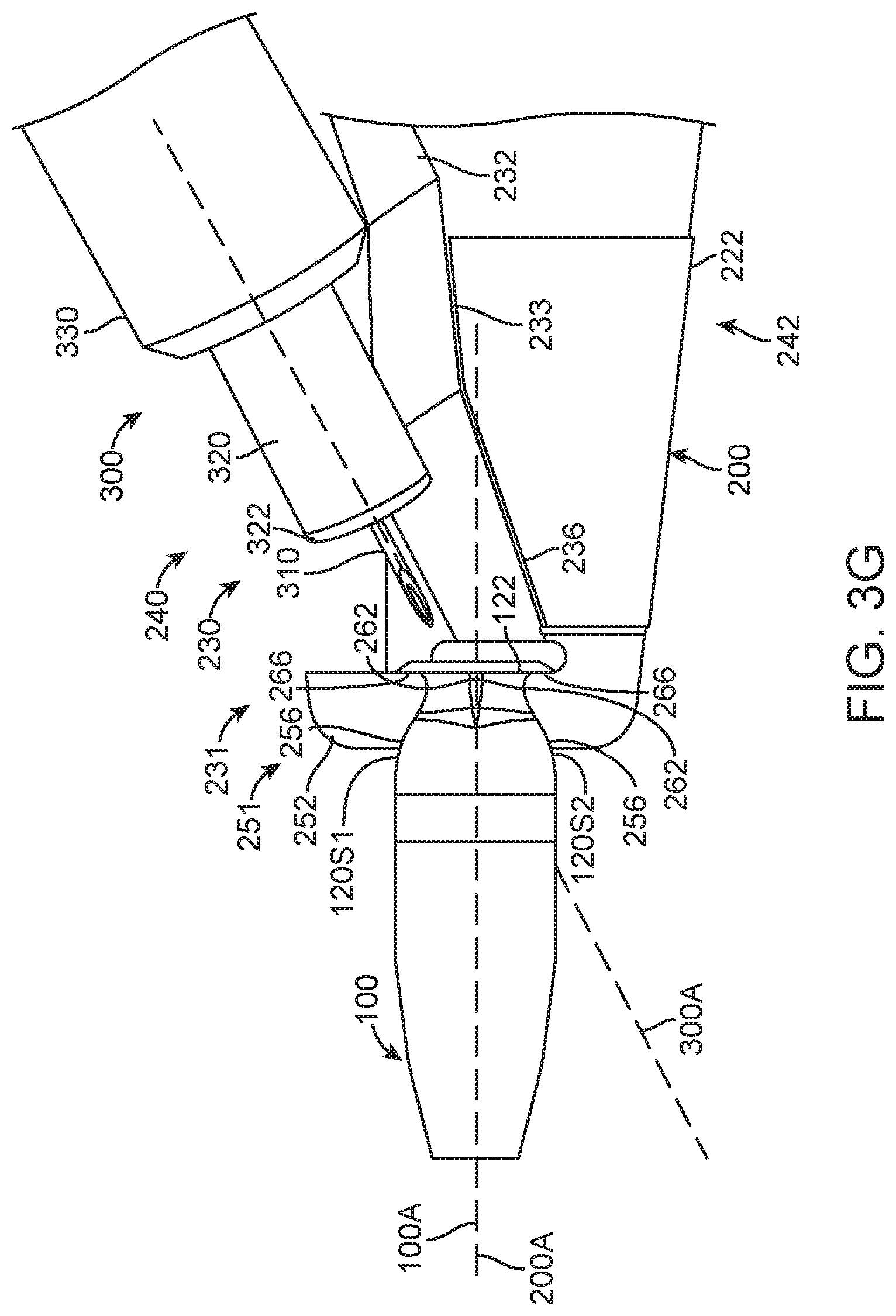
D00013

D00014

D00015

D00016

D00017
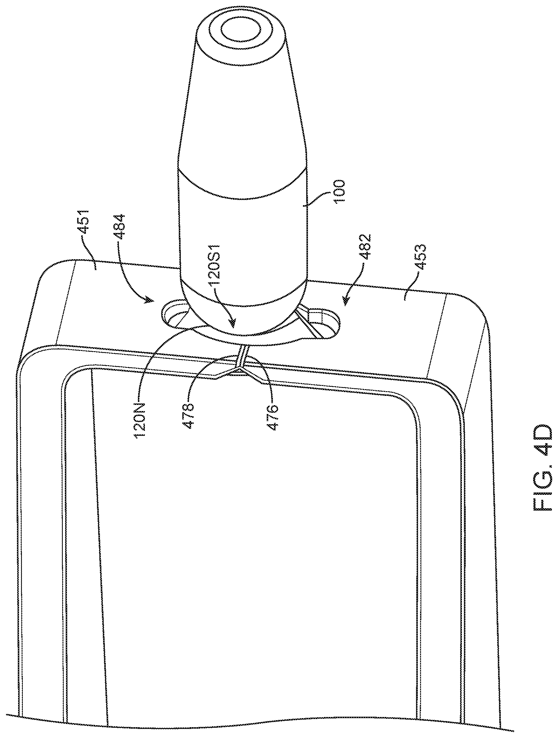
D00018
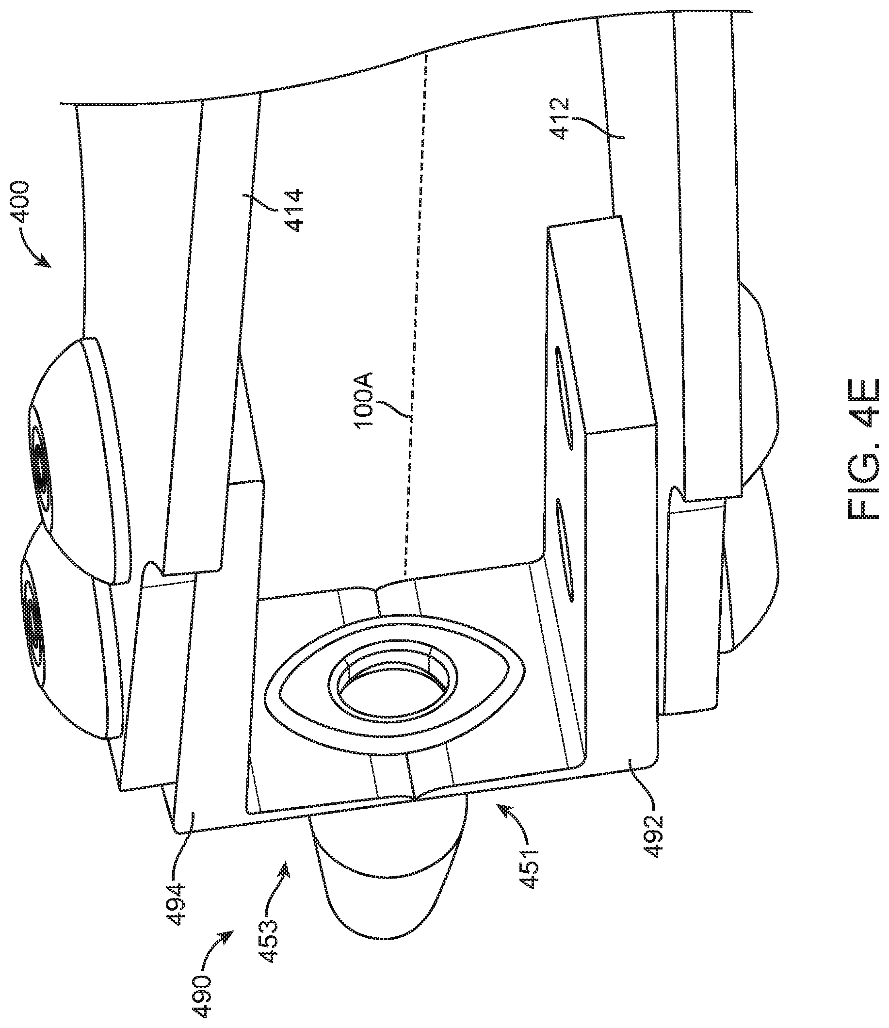
D00019

D00020
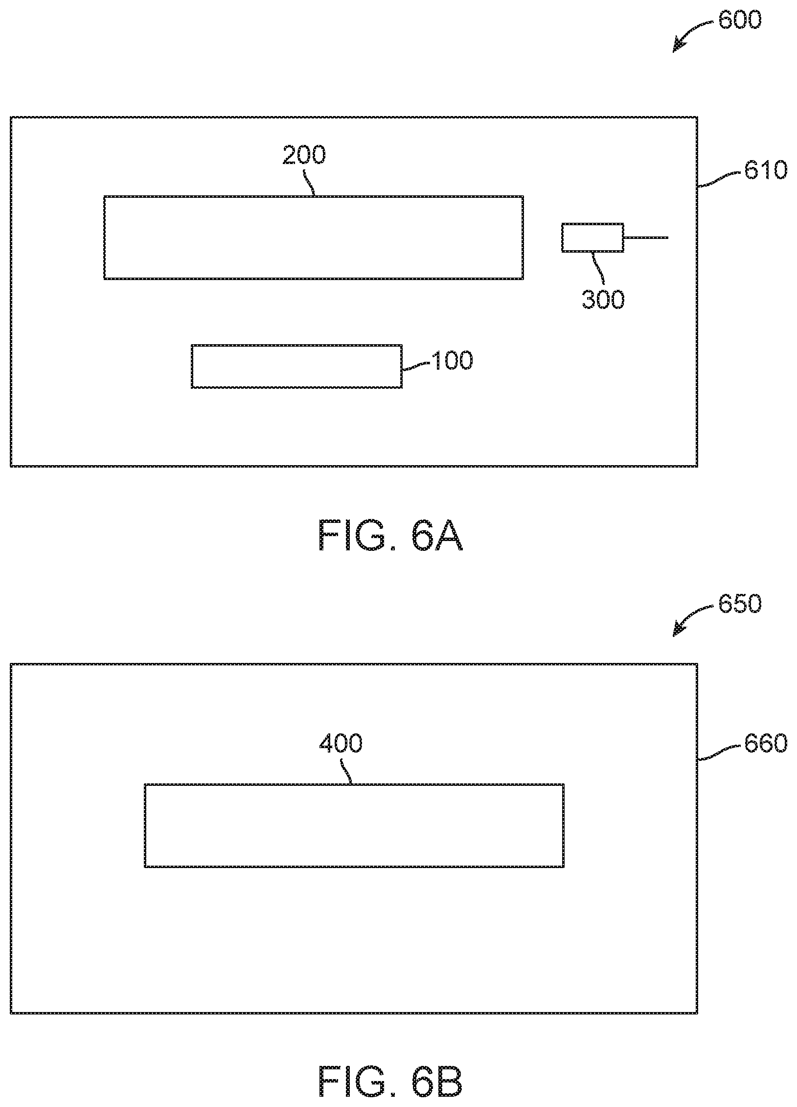
XML
uspto.report is an independent third-party trademark research tool that is not affiliated, endorsed, or sponsored by the United States Patent and Trademark Office (USPTO) or any other governmental organization. The information provided by uspto.report is based on publicly available data at the time of writing and is intended for informational purposes only.
While we strive to provide accurate and up-to-date information, we do not guarantee the accuracy, completeness, reliability, or suitability of the information displayed on this site. The use of this site is at your own risk. Any reliance you place on such information is therefore strictly at your own risk.
All official trademark data, including owner information, should be verified by visiting the official USPTO website at www.uspto.gov. This site is not intended to replace professional legal advice and should not be used as a substitute for consulting with a legal professional who is knowledgeable about trademark law.