Methods and systems for determining and displaying business relevance of telephonic communications between customers and a contact center
Conway , et al.
U.S. patent number 10,601,994 [Application Number 16/519,970] was granted by the patent office on 2020-03-24 for methods and systems for determining and displaying business relevance of telephonic communications between customers and a contact center. This patent grant is currently assigned to MATTERSIGHT CORPORATION. The grantee listed for this patent is Mattersight Corporation. Invention is credited to Douglas Brown, Kelly Conway, Christopher Danson, David Gustafson, Alan Yengoyan.
View All Diagrams
| United States Patent | 10,601,994 |
| Conway , et al. | March 24, 2020 |
Methods and systems for determining and displaying business relevance of telephonic communications between customers and a contact center
Abstract
The invention relates to a method and system for analyzing an electronic communication, more particularly, to analyzing telephonic communications between customers and a contact center to determine and display the most relevant communications to an organization or business.
| Inventors: | Conway; Kelly (Lake Bluff, IL), Yengoyan; Alan (Chicago, IL), Brown; Douglas (Austin, TX), Gustafson; David (Lake Bluff, IL), Danson; Christopher (Austin, TX) | ||||||||||
|---|---|---|---|---|---|---|---|---|---|---|---|
| Applicant: |
|
||||||||||
| Assignee: | MATTERSIGHT CORPORATION
(Chicago, IL) |
||||||||||
| Family ID: | 40563496 | ||||||||||
| Appl. No.: | 16/519,970 | ||||||||||
| Filed: | July 23, 2019 |
Prior Publication Data
| Document Identifier | Publication Date | |
|---|---|---|
| US 20190349478 A1 | Nov 14, 2019 | |
Related U.S. Patent Documents
| Application Number | Filing Date | Patent Number | Issue Date | ||
|---|---|---|---|---|---|
| 12286169 | Sep 29, 2008 | 10419611 | |||
| 60976372 | Sep 28, 2007 | ||||
| Current U.S. Class: | 1/1 |
| Current CPC Class: | H04M 3/5175 (20130101); H04M 3/42221 (20130101) |
| Current International Class: | H04M 3/51 (20060101); H04M 3/42 (20060101) |
| Field of Search: | ;379/265.06,265.07,266.01 |
References Cited [Referenced By]
U.S. Patent Documents
| 3851121 | November 1974 | Marvin |
| 3855416 | December 1974 | Fuller |
| 3855418 | December 1974 | Fuller |
| 3971034 | July 1976 | Bell, Jr. et al. |
| 4093821 | June 1978 | Williamson |
| 4142067 | February 1979 | Williamson |
| 4377158 | March 1983 | Friedman et al. |
| 4490840 | December 1984 | Jones |
| 4694483 | September 1987 | Cheung |
| 4811131 | March 1989 | Sander et al. |
| 4827461 | May 1989 | Sander |
| 4835630 | May 1989 | Freer |
| 4851937 | July 1989 | Sander |
| 4853952 | August 1989 | Jachmann et al. |
| 4864432 | September 1989 | Freer |
| 4873592 | October 1989 | Dulaff et al. |
| 4888652 | December 1989 | Sander |
| 4891835 | January 1990 | Leung et al. |
| 4893197 | January 1990 | Howells et al. |
| 4958367 | September 1990 | Freer et al. |
| 5003575 | March 1991 | Chamberlin et al. |
| 5008835 | April 1991 | Jachmann et al. |
| 5148483 | September 1992 | Silverman |
| 5148493 | September 1992 | Bruney |
| 5206903 | April 1993 | Kohler et al. |
| 5216744 | June 1993 | Alleyne et al. |
| 5239460 | August 1993 | LaRoche |
| 5274738 | December 1993 | Daly et al. |
| 5299260 | March 1994 | Shaio |
| 5339203 | August 1994 | Henits et al. |
| 5396371 | March 1995 | Henits et al. |
| 5446603 | August 1995 | Henits et al. |
| 5448420 | September 1995 | Henits et al. |
| 5457782 | October 1995 | Daly et al. |
| 5467391 | November 1995 | Donaghue et al. |
| 5500795 | March 1996 | Powers et al. |
| 5535256 | July 1996 | Maloney et al. |
| 5559875 | September 1996 | Bieselin et al. |
| 5561707 | October 1996 | Katz |
| 5577254 | November 1996 | Gilbert |
| 5590171 | December 1996 | Howe et al. |
| 5590188 | December 1996 | Crockett |
| 5594790 | January 1997 | Curren et al. |
| 5594791 | January 1997 | Szlam et al. |
| 5621789 | April 1997 | McCalmont et al. |
| 5633916 | May 1997 | Goldhagen et al. |
| 5646981 | July 1997 | Klein |
| 5696811 | December 1997 | Maloney et al. |
| 5710884 | January 1998 | Dedrick |
| 5712954 | January 1998 | Dezonno |
| 5717742 | February 1998 | Hyde-Thomson |
| 5721827 | February 1998 | Logan et al. |
| 5724420 | March 1998 | Torgrim |
| 5732216 | March 1998 | Logan et al. |
| 5734890 | March 1998 | Case et al. |
| 5737405 | April 1998 | Dezonno |
| 5757904 | May 1998 | Anderson |
| 5764728 | June 1998 | Ala et al. |
| 5768513 | June 1998 | Kuthyar et al. |
| 5784452 | June 1998 | Carney |
| 5790798 | August 1998 | Beckett, II et al. |
| 5799063 | August 1998 | Krane |
| 5809250 | September 1998 | Kisor |
| 5815551 | September 1998 | Katz |
| 5818907 | October 1998 | Maloney et al. |
| 5818909 | October 1998 | Van Berkum et al. |
| 5819005 | October 1998 | Daly et al. |
| 5822306 | October 1998 | Catchpole |
| 5822400 | October 1998 | Smith |
| 5822410 | October 1998 | McCausland et al. |
| 5822744 | October 1998 | Kesel |
| 5825869 | October 1998 | Brooks et al. |
| 5828730 | October 1998 | Zebryk et al. |
| 5841966 | November 1998 | Irribarren |
| 5845290 | December 1998 | Yoshii |
| 5848396 | December 1998 | Gerace |
| 5854832 | December 1998 | Dezonno |
| 5857175 | January 1999 | Day et al. |
| 5859898 | January 1999 | Checco |
| 5864616 | January 1999 | Hartmeier |
| 5870549 | February 1999 | Bobo, II |
| 5875436 | February 1999 | Kikinis |
| 5878384 | March 1999 | Johnson et al. |
| 5884032 | March 1999 | Bateman et al. |
| 5884262 | March 1999 | Wise et al. |
| 5894512 | April 1999 | Zenner |
| 5897616 | April 1999 | Kanevsky et al. |
| 5903641 | May 1999 | Tonisson |
| 5910107 | June 1999 | Iliff |
| 5911776 | June 1999 | Guck |
| 5914951 | June 1999 | Bentley et al. |
| 5915001 | June 1999 | Uppaluru |
| 5915011 | June 1999 | Miloslavsky |
| 5923746 | July 1999 | Baker |
| 5926538 | July 1999 | Deryugen |
| 5930764 | July 1999 | Melchione et al. |
| 5937029 | August 1999 | Yosef |
| 5940476 | August 1999 | Morganstein et al. |
| 5940494 | August 1999 | Rafacz |
| 5940792 | August 1999 | Hollier |
| 5943416 | August 1999 | Gisby |
| 5945989 | August 1999 | Freishtat |
| 5946375 | August 1999 | Pattison et al. |
| 5946388 | August 1999 | Walker et al. |
| 5951643 | September 1999 | Shelton et al. |
| 5953389 | September 1999 | Pruett |
| 5953406 | September 1999 | LaRue et al. |
| 5964839 | October 1999 | Johnson et al. |
| 5978465 | November 1999 | Corduroy et al. |
| 5987415 | November 1999 | Breese et al. |
| 5991735 | November 1999 | Gerace |
| 6003013 | December 1999 | Boushy et al. |
| 6006188 | December 1999 | Bogdashevsky et al. |
| 6009163 | December 1999 | Nabkel et al. |
| 6014647 | January 2000 | Nizzari et al. |
| 6021428 | February 2000 | Miloslavsky |
| 6026397 | February 2000 | Sheppard |
| 6029153 | February 2000 | Bauchner et al. |
| 6058163 | May 2000 | Pattison et al. |
| 6064731 | May 2000 | Flockhart et al. |
| 6078891 | June 2000 | Riordan |
| 6108711 | August 2000 | Beck et al. |
| 6128380 | October 2000 | Shaffer et al. |
| 6151571 | November 2000 | Pertrushin |
| 6173053 | January 2001 | Bogart et al. |
| 6185534 | February 2001 | Breese et al. |
| 6195426 | February 2001 | Bolduc et al. |
| 6205215 | March 2001 | Dombakly |
| 6212502 | April 2001 | Ball et al. |
| 6243684 | June 2001 | Stuart et al. |
| 6246752 | June 2001 | Bscheider et al. |
| 6249570 | June 2001 | Glowny et al. |
| 6252946 | June 2001 | Glowny et al. |
| 6252947 | June 2001 | Diamond et al. |
| 6275806 | August 2001 | Pertrushin |
| 6286030 | September 2001 | Wenig et al. |
| 6289094 | September 2001 | Miloslavsky |
| 6295353 | September 2001 | Flockhart et al. |
| 6330025 | December 2001 | Arazi et al. |
| 6334110 | December 2001 | Walter et al. |
| 6345094 | February 2002 | Khan et al. |
| 6353810 | March 2002 | Petrushin |
| 6363145 | March 2002 | Shaffer et al. |
| 6363346 | March 2002 | Walters |
| 6366658 | April 2002 | Bjornberg et al. |
| 6366666 | April 2002 | Bengston et al. |
| 6370574 | April 2002 | House et al. |
| 6389132 | May 2002 | Price |
| 6392666 | May 2002 | Hong et al. |
| 6404857 | June 2002 | Blair et al. |
| 6404883 | June 2002 | Hartmeier |
| 6411687 | June 2002 | Bohacek et al. |
| 6411708 | June 2002 | Khan |
| 6424709 | July 2002 | Doyle et al. |
| 6434230 | August 2002 | Gabriel |
| 6434231 | August 2002 | Neyman et al. |
| 6446119 | September 2002 | Olah et al. |
| 6466663 | October 2002 | Ravenscroft et al. |
| 6480601 | November 2002 | McLaughlin |
| 6480826 | November 2002 | Petrushin |
| 6490560 | December 2002 | Ramaswamy et al. |
| 6510220 | January 2003 | Beckett et al. |
| 6535601 | March 2003 | Flockhart et al. |
| 6542156 | April 2003 | Hong et al. |
| 6542602 | April 2003 | Elazar |
| 6553112 | April 2003 | Ishikawa |
| 6556976 | April 2003 | Callen |
| 6567504 | May 2003 | Kercheval et al. |
| 6567787 | May 2003 | Walker et al. |
| 6574605 | June 2003 | Sanders et al. |
| 6598020 | July 2003 | Kleindienst et al. |
| 6600821 | July 2003 | Chan et al. |
| 6601031 | July 2003 | O'Brien |
| 6611498 | August 2003 | Baker et al. |
| 6628777 | September 2003 | McIllwaine et al. |
| 6643622 | November 2003 | Stuart et al. |
| 6647372 | November 2003 | Brady et al. |
| 6658388 | December 2003 | Kleindienst et al. |
| 6658391 | December 2003 | Williams et al. |
| 6662156 | December 2003 | Bartosik |
| 6665644 | December 2003 | Kanevsky et al. |
| 6674447 | January 2004 | Chiang et al. |
| 6691073 | February 2004 | Erten et al. |
| 6700972 | March 2004 | McGugh et al. |
| 6721417 | April 2004 | Saito et al. |
| 6721704 | April 2004 | Strubbe et al. |
| 6724887 | April 2004 | Eilbacher et al. |
| 6728345 | April 2004 | Glowny et al. |
| 6731307 | May 2004 | Strubbe et al. |
| 6731744 | May 2004 | Khuc et al. |
| 6735298 | May 2004 | Neyman et al. |
| 6741697 | May 2004 | Benson et al. |
| 6744877 | June 2004 | Edwards |
| 6751297 | June 2004 | Nelkenbaum |
| 6757361 | June 2004 | Blair et al. |
| 6760414 | July 2004 | Schurko et al. |
| 6760727 | July 2004 | Schroeder et al. |
| 6766012 | July 2004 | Crossley |
| 6775372 | August 2004 | Henits |
| 6782093 | August 2004 | Uckun |
| 6785369 | August 2004 | Diamond et al. |
| 6785370 | August 2004 | Glowny et al. |
| 6788768 | September 2004 | Saylor et al. |
| 6798876 | September 2004 | Bala |
| 6839671 | January 2005 | Attwater et al. |
| 6842405 | January 2005 | D'Agosto, III |
| 6853966 | February 2005 | Bushey et al. |
| 6864901 | March 2005 | Chang et al. |
| 6865604 | March 2005 | Nisani et al. |
| 6868392 | March 2005 | Ogasawara |
| 6870920 | March 2005 | Henits |
| 6871229 | March 2005 | Nisani et al. |
| 6880004 | April 2005 | Nisani et al. |
| 6937706 | August 2005 | Bscheider et al. |
| 6959078 | October 2005 | Eilbacher et al. |
| 6959079 | October 2005 | Elazar |
| 7010106 | March 2006 | Gritzer et al. |
| 7010109 | March 2006 | Gritzer et al. |
| 7027708 | April 2006 | Nygren et al. |
| 7043745 | May 2006 | Nygren et al. |
| 7149788 | December 2006 | Gundla et al. |
| 7203285 | April 2007 | Blair |
| 7216162 | May 2007 | Amit et al. |
| 7219138 | May 2007 | Straut et al. |
| 7305082 | December 2007 | Elazar et al. |
| 7333445 | February 2008 | Ilan et al. |
| 7346186 | March 2008 | Sharoni et al. |
| 7376735 | May 2008 | Straut et al. |
| 7664641 | February 2010 | Pettay et al. |
| 2001/0043685 | November 2001 | Bscheider et al. |
| 2002/0002460 | January 2002 | Perturshin |
| 2002/0002464 | January 2002 | Petrushin |
| 2002/0010587 | January 2002 | Perturshin |
| 2002/0110264 | August 2002 | Sharoni et al. |
| 2002/0111811 | August 2002 | Bares et al. |
| 2002/0133394 | September 2002 | Bushey et al. |
| 2002/0143599 | October 2002 | Nourbakhsh et al. |
| 2002/0194002 | December 2002 | Petrushin |
| 2003/0033145 | February 2003 | Petrushin |
| 2003/0033152 | February 2003 | Cameron |
| 2003/0069780 | April 2003 | Hailwood et al. |
| 2003/0072463 | April 2003 | Chen |
| 2003/0142122 | July 2003 | Straut et al. |
| 2003/0144900 | July 2003 | Whitmer |
| 2003/0145140 | July 2003 | Straut et al. |
| 2003/0154092 | August 2003 | Bouron et al. |
| 2004/0041830 | March 2004 | Chiang et al. |
| 2004/0054715 | March 2004 | Cesario |
| 2004/0073569 | April 2004 | Knott et al. |
| 2004/0100507 | May 2004 | Hayner et al. |
| 2004/0101127 | May 2004 | Dezonno et al. |
| 2004/0103409 | May 2004 | Hayner et al. |
| 2004/0117185 | June 2004 | Scarano et al. |
| 2004/0158869 | August 2004 | Safran et al. |
| 2004/0162724 | August 2004 | Hill et al. |
| 2004/0181376 | September 2004 | Fables et al. |
| 2004/0190687 | September 2004 | Baker |
| 2004/0249636 | December 2004 | Applebaum |
| 2004/0249650 | December 2004 | Freedman et al. |
| 2004/0264652 | December 2004 | Erhart et al. |
| 2005/0010411 | January 2005 | Rigazio et al. |
| 2005/0010415 | January 2005 | Hagen et al. |
| 2005/0010598 | January 2005 | Shankar |
| 2005/0018622 | January 2005 | Halbraich et al. |
| 2005/0108383 | May 2005 | DeHaas et al. |
| 2005/0108775 | May 2005 | Bachar et al. |
| 2005/0123115 | June 2005 | Gritzer et al. |
| 2005/0204378 | September 2005 | Gabay |
| 2005/0240656 | October 2005 | Blair |
| 2006/0028488 | February 2006 | Gabay et al. |
| 2006/0045185 | March 2006 | Kiryati et al. |
| 2006/0074898 | April 2006 | Gavalda et al. |
| 2006/0089837 | April 2006 | Adar et al. |
| 2006/0106670 | May 2006 | Cai et al. |
| 2006/0111904 | May 2006 | Wasserblat et al. |
| 2006/0123106 | June 2006 | Blair et al. |
| 2006/0126817 | June 2006 | Beckett, II et al. |
| 2006/0133624 | June 2006 | Waserblat et al. |
| 2006/0150229 | July 2006 | Blair et al. |
| 2006/0168188 | July 2006 | Dutton |
| 2006/0200520 | September 2006 | Wasserblat et al. |
| 2006/0200832 | October 2006 | Halbraich |
| 2006/0212295 | November 2006 | Halbraich et al. |
| 2006/0262920 | November 2006 | Conway |
| 2006/0262922 | November 2006 | Margulies |
| 2006/0268847 | November 2006 | Halbraich et al. |
| 2006/0227719 | December 2006 | Wasserblat et al. |
| 2006/0285665 | December 2006 | Wasserblat et al. |
| 2007/0019634 | April 2007 | Gundla et al. |
| 2007/0083540 | May 2007 | Blumenau |
| 2007/0094408 | May 2007 | Blumenau |
| 2007/0121824 | May 2007 | Agapi et al. |
| 2007/0127693 | June 2007 | D'Ambrosio et al. |
| 2007/0106791 | July 2007 | Blair |
| 2007/0106792 | July 2007 | Blair |
| 2007/0160189 | July 2007 | Blair |
| 2007/0160190 | August 2007 | Korenblit et al. |
| 2007/0160191 | August 2007 | Korenblit et al. |
| 2007/0195944 | August 2007 | Korenblit et al. |
| 2007/0195945 | August 2007 | Bourne et al. |
| 2007/0198284 | August 2007 | Bourne et al. |
| 2007/0198322 | August 2007 | Lyerly et al. |
| 2007/0198323 | August 2007 | Lyerly et al. |
| 2007/0198325 | August 2007 | Korenblit et al. |
| 2007/0198329 | September 2007 | Keren et al. |
| 2007/0198330 | September 2007 | Keren et al. |
| 2007/0206764 | September 2007 | Keren et al. |
| 2007/0206766 | September 2007 | Bourne et al. |
| 2007/0206767 | September 2007 | Blair |
| 2007/0206768 | October 2007 | Spohrer et al. |
| 2007/0217576 | October 2007 | Williams et al. |
| 2007/0230345 | October 2007 | Williams et al. |
| 2007/0230444 | October 2007 | Dong et al. |
| 2007/0237525 | October 2007 | Spohrer et al. |
| 2007/0250318 | October 2007 | Waserblat et al. |
| 2007/0258434 | November 2007 | Williams et al. |
| 2007/0263785 | November 2007 | Williams et al. |
| 2007/0263786 | November 2007 | Dong et al. |
| 2007/0263787 | November 2007 | Dong et al. |
| 2007/0263788 | November 2007 | Spohrer et al. |
| 2007/0274505 | November 2007 | Gupta et al. |
| 2007/0282807 | December 2007 | Ringelman et al. |
| 2007/0297578 | December 2007 | Blair et al. |
| 2008/0002719 | January 2008 | Byrd et al. |
| 2008/0002823 | January 2008 | Fama et al. |
| 2008/0004945 | January 2008 | Watson et al. |
| 2008/0005307 | January 2008 | Byrd et al. |
| 2008/0005318 | January 2008 | Dong et al. |
| 2008/0005568 | January 2008 | Watson et al. |
| 2008/0005569 | January 2008 | Watson et al. |
| 2008/0005588 | January 2008 | Watson et al. |
| 2008/0040110 | February 2008 | Pereg et al. |
| 2008/0052535 | February 2008 | Spohrer et al. |
| 2008/0065902 | March 2008 | Spohrer et al. |
| 2008/0080385 | April 2008 | Blair |
| 2008/0080386 | April 2008 | Calahan et al. |
| 2008/0080481 | April 2008 | Calahan et al. |
| 2008/0080482 | April 2008 | Calahan et al. |
| 2008/0080483 | April 2008 | Calahan et al. |
| 2008/0080531 | April 2008 | Williams et al. |
| 2008/0080685 | April 2008 | Barnes et al. |
| 2008/0080698 | April 2008 | Williams et al. |
| 2008/0082329 | April 2008 | Watson |
| 2008/0082330 | April 2008 | Blair |
| 2008/0082336 | April 2008 | Duke et al. |
| 2008/0082340 | April 2008 | Blair et al. |
| 2008/0082341 | April 2008 | Blair |
| 2008/0082502 | April 2008 | Gupta |
| 2008/0082669 | April 2008 | Williams et al. |
| 2008/0152122 | June 2008 | Ldan et al. |
| 2009/0103709 | April 2009 | Conway et al. |
| 0862304 | Sep 1998 | EP | |||
| 0863678 | Sep 1998 | EP | |||
| 0998108 | May 2000 | EP | |||
| 1361739 | Nov 2003 | EP | |||
| 1635534 | Mar 2006 | EP | |||
| 1377907 | Nov 2006 | EP | |||
| 2331201 | May 1999 | GB | |||
| 2389736 | Dec 2003 | GB | |||
| 2001074042 | Oct 2001 | WO | |||
| 2002017165 | Feb 2002 | WO | |||
| 2002073413 | Sep 2002 | WO | |||
| 2003001809 | Jan 2003 | WO | |||
| 2003009175 | Jan 2003 | WO | |||
| 2006124942 | Nov 2006 | WO | |||
| 2006124945 | Nov 2006 | WO | |||
| 2006125047 | Nov 2006 | WO | |||
| 2007100345 | Sep 2007 | WO | |||
| 2007106113 | Sep 2007 | WO | |||
Assistant Examiner: Intavong; Jirapon
Attorney, Agent or Firm: Haynes and Boone, LLC
Parent Case Text
CROSS-REFERENCE TO RELATED APPLICATION
This application is a divisional application of U.S. patent application Ser. No. 12/286,169, filed Sep. 29, 2008, now allowed, which claims the benefit of U.S. Provisional Patent Application No. 60/976,372, filed Sep. 28, 2007, the disclosure of each of which is hereby incorporated herein by express reference thereto.
Claims
What is claimed is:
1. A system for identifying trends in electronic communications received by a contact center, the system comprising: a first server for recording a plurality of electronic communications of an organization; a node comprising a processor and a non-transitory computer readable medium operably coupled thereto, the non-transitory computer readable medium comprising a plurality of instructions stored in association therewith that are accessible to, and executable by, the processor, where the plurality of instructions comprises: instructions that, when executed, apply linguistic and non-linguistic analysis to the plurality of electronic communications; instructions that, when executed, identify one or more patterns in the plurality of electronic communications over a first predetermined period of time; instructions that, when executed, determine the frequency for each pattern in the plurality of electronic communications over the first predetermined period of time; instructions that, when executed, determine the significance of each identified pattern over the first predetermined period of time; instructions that, when executed, determine a trend for each of the one or more patterns based on the frequency and significance of the pattern over the first predetermined period of time; instructions that, when executed, generate one or more recommended actions based on each determined trend; instructions that, when executed, display the one or more recommended actions to a user; and instructions that, when executed, transmit each of the electronic communications exhibiting each determined trend to a specific area of the organization.
2. The system of claim 1, which further comprises instructions that, when executed, identify one or more patterns in the plurality of electronic communications over a second predetermined period of time; instructions that, when executed, determine the frequency for each pattern in the plurality of electronic communications over the second predetermined period of time; instructions that, when executed, determine the significance of each identified pattern over the second predetermined period of time; and instructions that, when executed, determine a trend for each of the one or more patterns based on the frequency and significance of the pattern over the second predetermined period of time.
3. The system of claim 2, wherein the first and second predetermined periods of time are sequential and do not overlap.
4. The system of claim 1, which further comprises instructions that, when executed, transmit the one or more recommended actions to a communication distributor.
5. The system of claim 1, wherein the instructions that, when executed, identifies one or more patterns further comprises establishing a frequency threshold, and including patterns that exceed the frequency threshold in the identified patterns.
6. The system of claim 1, which further comprises a routing engine configured to send an automated message to an external source based on the determined trend.
7. The system of claim 2, wherein the instructions that, when executed, generate one or more recommended actions based on each identified trend, are further based on a comparison of a first plurality of patterns from the first predetermined time period to a second plurality of patterns from the second predetermined time period.
8. A computer-implemented method for identifying trends in electronic communications between one or more customers of an organization and a contact center having one or more agents, the method being implemented by a non-transitory computer readable medium adapted to control a computer and comprising a plurality of code segments, the method comprising: recording a plurality of electronic communications; applying linguistic and non-linguistic analysis to the plurality of electronic communications; identifying one or more patterns in the plurality of electronic communications over a first predetermined period of time; determining the frequency for each pattern in the plurality of electronic communications over the first predetermined period of time; determining the significance of each identified pattern over the first predetermined period of time; determining a trend for each of the one or more patterns based on the frequency and significance of the pattern over the first predetermined period of time; generating one or more recommended actions based on each determined trend; displaying the one or more recommended actions to a user; and transmitting each of the electronic communications exhibiting each determined trend to a specific area of the organization.
9. The computer-implemented method of claim 8, which further comprises: identifying one or more patterns in the plurality of electronic communications over a second predetermined period of time; determining the frequency for each pattern in the plurality of electronic communications over the second predetermined period of time; determining the significance of each identified pattern over the second predetermined period of time; and determining a trend for each of the one or more patterns based on the frequency and significance of the pattern over the second predetermined period of time.
10. The computer-implemented method of claim 9, wherein the first and second predetermined periods of time are sequential and do not overlap.
11. The computer-implemented method of claim 8, which further comprises transmitting the one or more recommended actions to a communication distributor.
12. The computer-implemented method of claim 8, wherein the identifying one or more patterns further comprises establishing a frequency threshold, and including patterns that exceed the frequency threshold in the identified patterns.
13. The computer-implemented method of claim 8, which further comprises sending an automated message to an external source based on the determined trend.
14. The computer-implemented method of claim 9, wherein the generating one or more recommended actions based on each identified trend is further based on a comparison of a first plurality of patterns from the first predetermined time period to a second plurality of patterns from the second predetermined time period.
15. A non-transitory machine-readable medium comprising a plurality of machine-readable instructions which, when executed by one or more processors, are adapted to cause the one or more processors to perform a method which comprises: recording a plurality of electronic communications of an organization; applying linguistic and non-linguistic analysis to the plurality of electronic communications; identifying one or more patterns in the plurality of electronic communications over a first predetermined period of time; determining the frequency for each pattern in the plurality of electronic communications over the first predetermined period of time; determining the significance of each identified pattern over the first predetermined period of time; determining a trend for each of the one or more patterns based on the frequency and significance of the pattern over the first predetermined period of time; generating one or more recommended actions based on each determined trend; displaying the one or more recommended actions to a user; and transmitting each of the electronic communications exhibiting each determined trend to a specific area of the organization.
16. The non-transitory machine-readable medium of claim 15, wherein the method further comprises: identifying one or more patterns in the plurality of electronic communications over a second predetermined period of time; determining the frequency for each pattern in the plurality of electronic communications over the second predetermined period of time; determining the significance of each identified pattern over the second predetermined period of time; and determining a trend for each of the one or more patterns based on the frequency and significance of the pattern over the second predetermined period of time.
17. The non-transitory machine-readable medium of claim 16, wherein the first and second predetermined periods of time are sequential and do not overlap.
18. The non-transitory machine-readable medium of claim 15, wherein the identifying one or more patterns further comprises establishing a frequency threshold, and including patterns that exceed the frequency threshold in the identified patterns.
19. The non-transitory machine-readable medium of claim 16, wherein the generating one or more recommended actions based on each identified trend is further based on a comparison of a first plurality of patterns from the first predetermined time period to a second plurality of patterns from the second predetermined time period.
Description
TECHNICAL FIELD
The invention relates to a method and system for analyzing an electronic communication, more particularly, to analyzing telephonic communications between customers and a contact center to determine and display the most relevant communications to an organization or business.
BACKGROUND OF THE DISCLOSURE
It is known to utilize telephone call centers to facilitate the receipt, response and routing of incoming-telephone calls relating to customer service, retention, and sales. Generally, a customer is in contact with a customer service representative ("CSR") or call center agent who is responsible for answering the customer's inquiries and/or directing the customer to the appropriate individual, department, information source, or service as required to satisfy the customer's needs. It is also known to utilize a web based system to facilitate requests and inquiries related to customer service.
At the contact center, a customer is in contact with a customer service representative ("CSR") or CSR agent who is responsible for answering the customer's inquiries and directing the customer to the appropriate individual, department, information source, or service as required to satisfy the customer's needs. At the contact center, the customer may also enter into an automated self-service system such as, for example, an interactive voice response ("IVR") system. In an IVR system, the customer speaks to the IVR system directly and has the call processed accordingly. It is also well known to provide self-service systems such as an Internet web-based system to transmit inquiries and identify possible solutions.
It is also known to monitor calls between a customer and a call center agent. Accordingly, call centers typically employ individuals responsible for listening to the conversation between the customer and the agent. Many companies have in-house call centers to respond to customers complaints and inquiries. In many case, however, it has been found to be cost effective for a company to hire third party telephone call centers to handle such inquiries. As such, the call centers may be located thousands of miles away from the actual sought manufacturer or individual. This often results in use of inconsistent and subjective methods of monitoring, training and evaluating call center agents. These methods also may vary widely from call center to call center.
While monitoring such calls may occur in real time, it is often more efficient and useful to record the call for later review. Information gathered from the calls is typically used to monitor the performance of the call center agents to identify possible training needs. Based on the review and analysis of the conversation, a monitor can make suggestions or recommendations to improve the quality of the customer interaction. However, with thousands of telephonic communications between customers and call centers on a daily basis, it is difficult for a business or organization to identify which calls and portions of calls are the most relevant from the thousands of calls received.
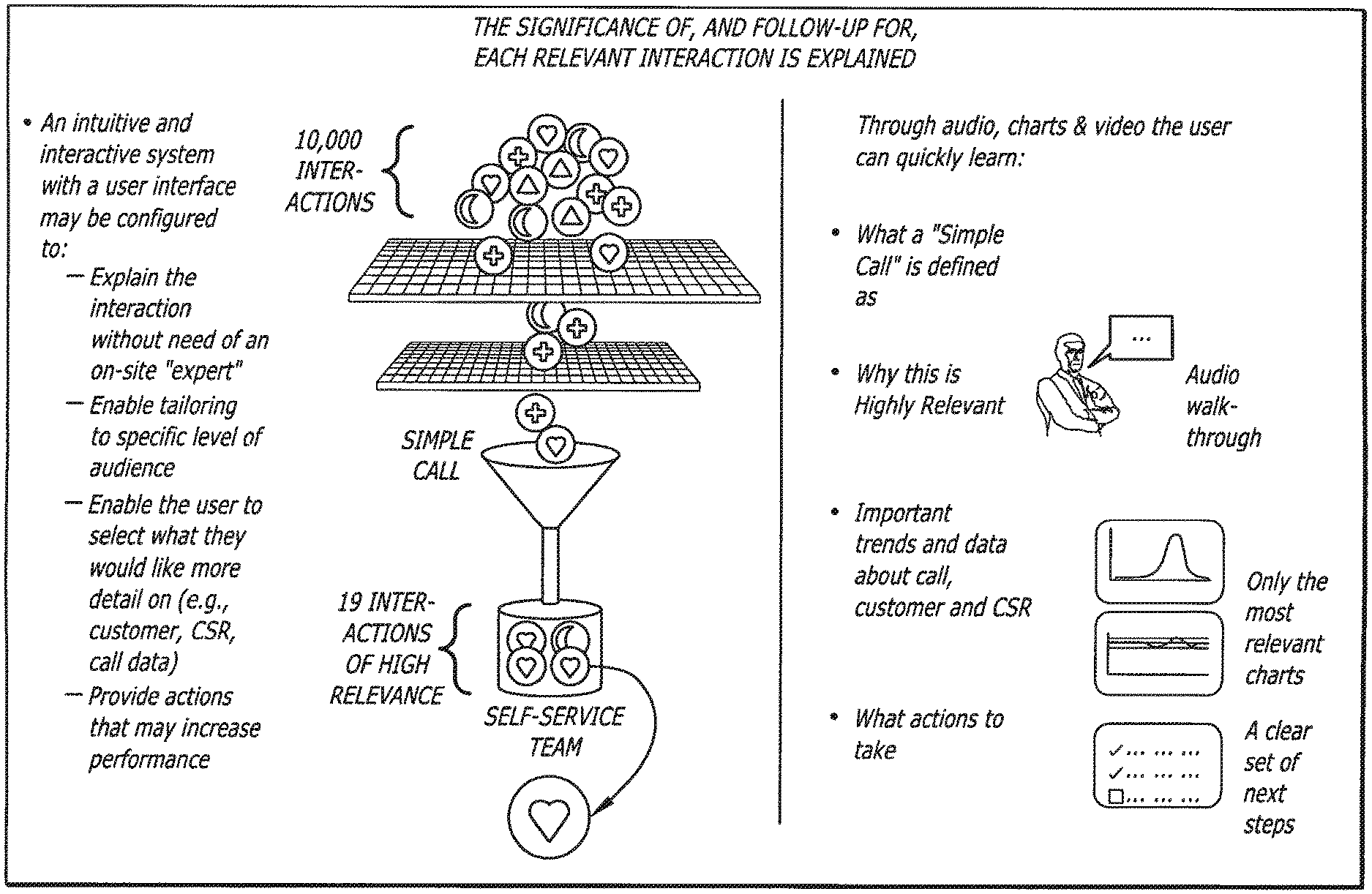
Accordingly, there is a need in customer relationship management ("CRM") for tools useful for breaking down a communication between a customer and a CSR into objects and segments that may be classified into categories for analysis. From these segments, it is desirable to determine the most relevant interactions between CSRs and customers to identify the most highly relevant communications for a business or organization. It is also desirable to provide the identified relevant interactions to specific parts of a business or organization with specific follow-through actions. It is also desirable to provide an interactive user interface that provides the identified highly relevant interaction and explains the significance of the interaction for the business or organization.
The present invention is provided to solve the problems discussed above and other problems, and to provide advantages and aspects not provided by prior systems of this type. A full discussion of the features and advantages of the present invention is deferred to the following detailed description, which proceeds with reference to the accompanying drawings.
SUMMARY
An exemplary method for analyzing a plurality of telephonic communications between one or more customers and a contact center is disclosed. The method may comprise determining one or more interaction outcomes that are meaningful to one or more parts of an organization. The method may further comprise identifying relevant interactions from the plurality of telephonic communications, wherein the identifying comprises applying a predefined set of rules the are to the plurality of telephonic communications. The identified relevant interactions may be provided to one or more respective parts of the organization.
Additionally, the exemplary method may further comprise providing explanatory information for the identified relevant telephonic communications to the one or more respective parts of the organization. The method may further comprise providing one or more follow-up actions for the identified relevant telephonic communications to the one or more respective parts of the organization. In addition, the predefined set of rules used to identify the relevant interaction may includes at least one of the one or more interaction outcomes.
The disclosure also encompasses program products for implementing the method outlined-above. In such a product, the programming is embodied in or carried on a machine-readable medium.
Other features and advantages of the invention will be apparent from the following specification taken in conjunction with the following drawings.
BRIEF DESCRIPTION OF THE DRAWINGS
To understand the present invention, it will now be described by way of example, with reference to the accompanying drawings in which:
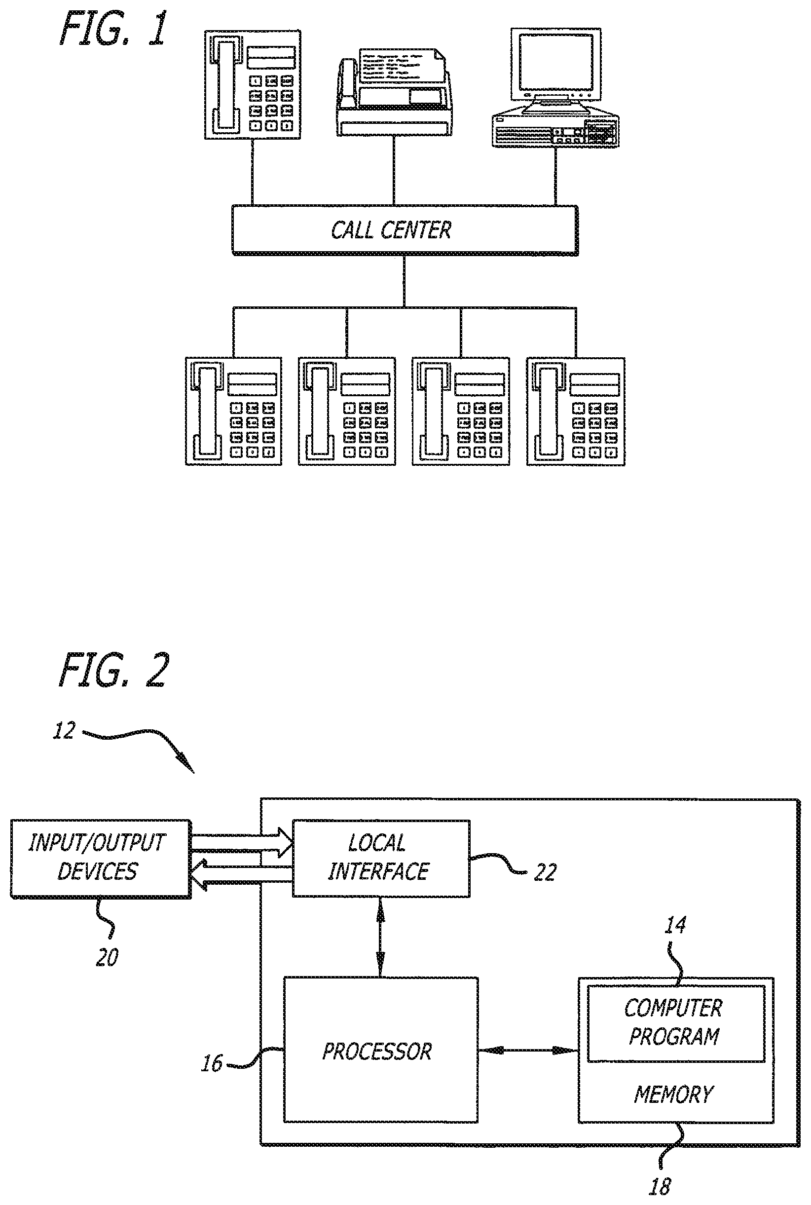
FIG. 1 is a block diagram of call center;
FIG. 2 is a block diagram of a computer used in connection with an exemplary embodiment of the present invention;
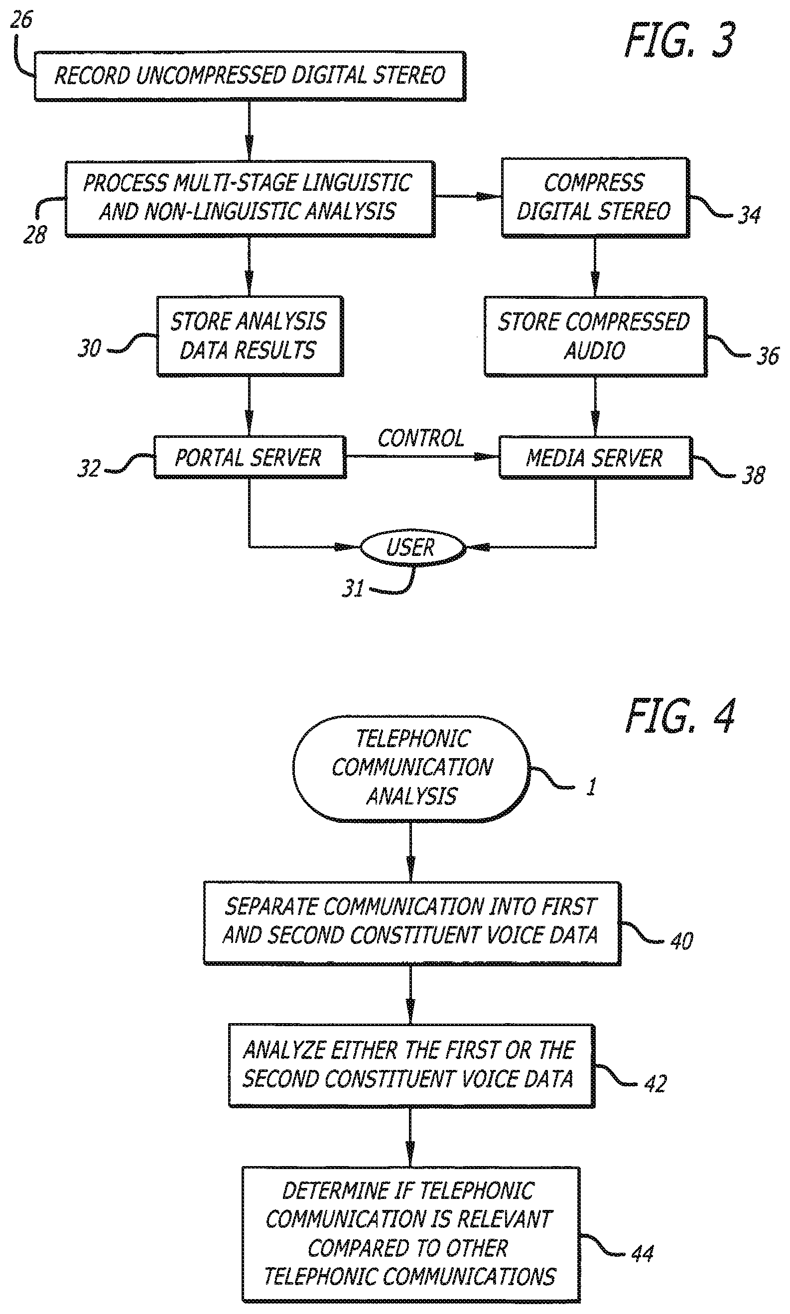
FIG. 3 is a flow chart illustrating the process of analyzing a telephonic communication in accordance with an exemplary embodiment of the present invention;
FIG. 4 is a flow chart illustrating the process of analyzing a telephonic communication in accordance with an exemplary embodiment of the present invention;
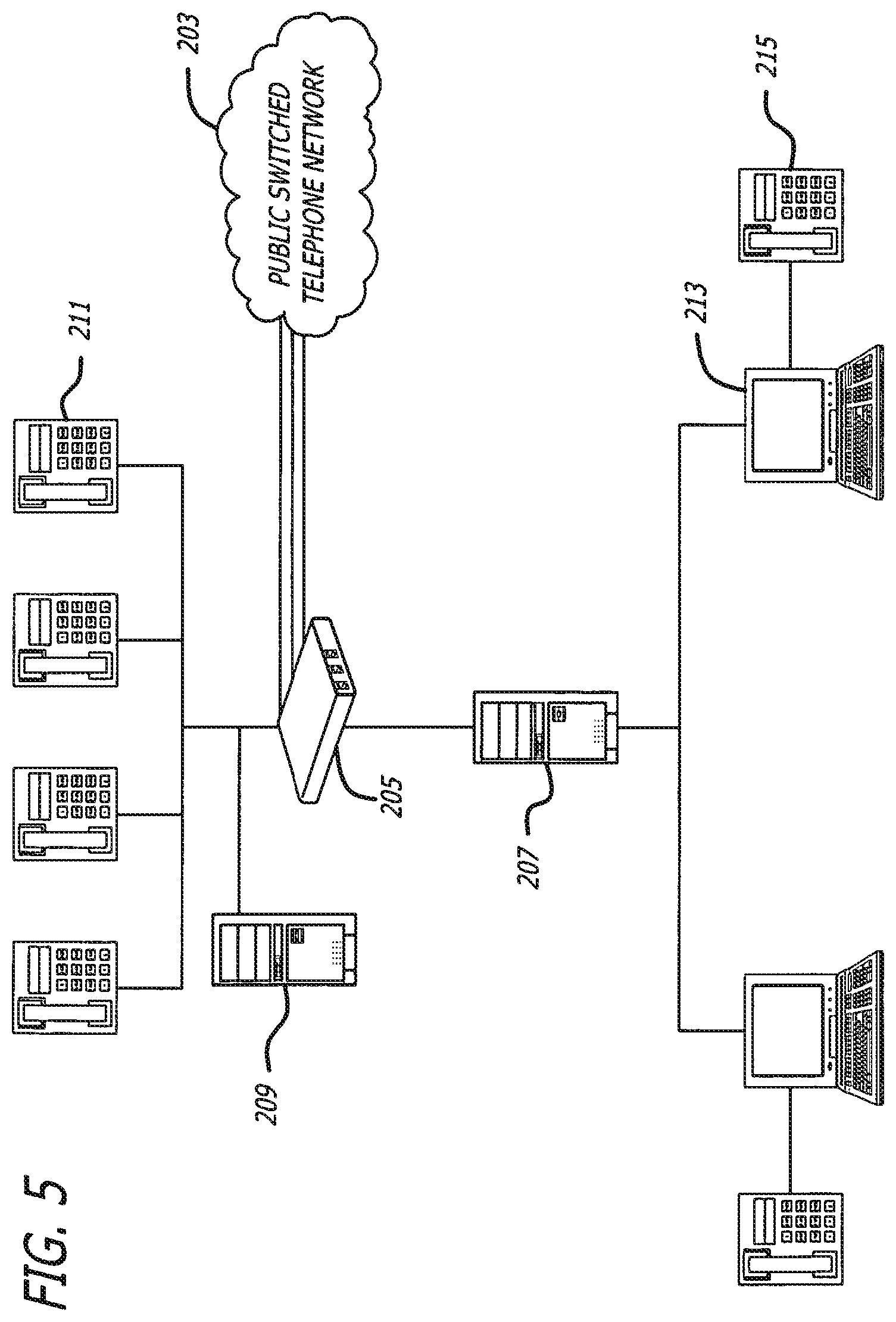
FIG. 5 is a block diagram of a telephonic communication system according to an exemplary embodiment of the present invention;
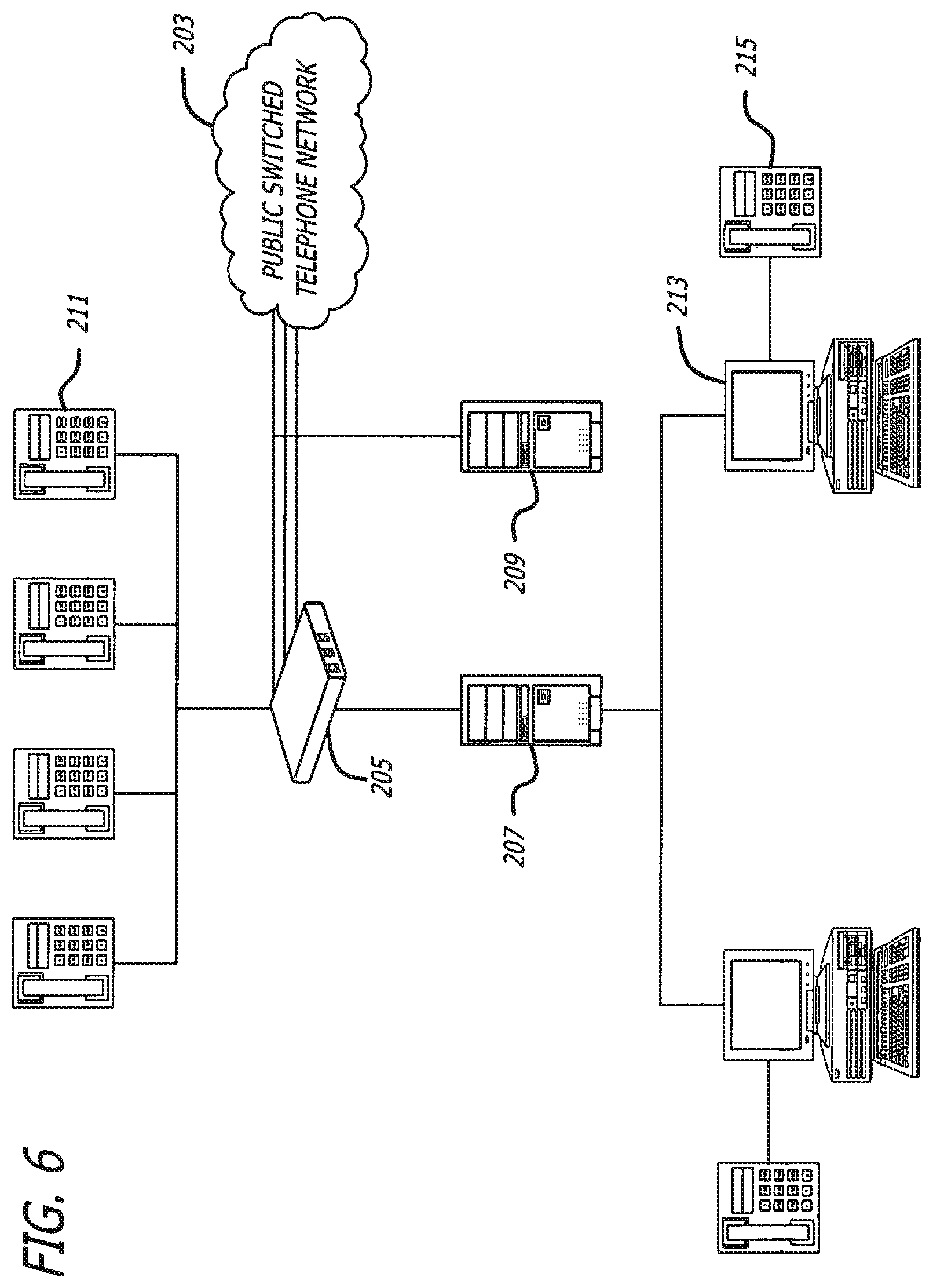
FIG. 6 is a block diagram of a telephonic communication system according to an exemplary embodiment of the present invention;
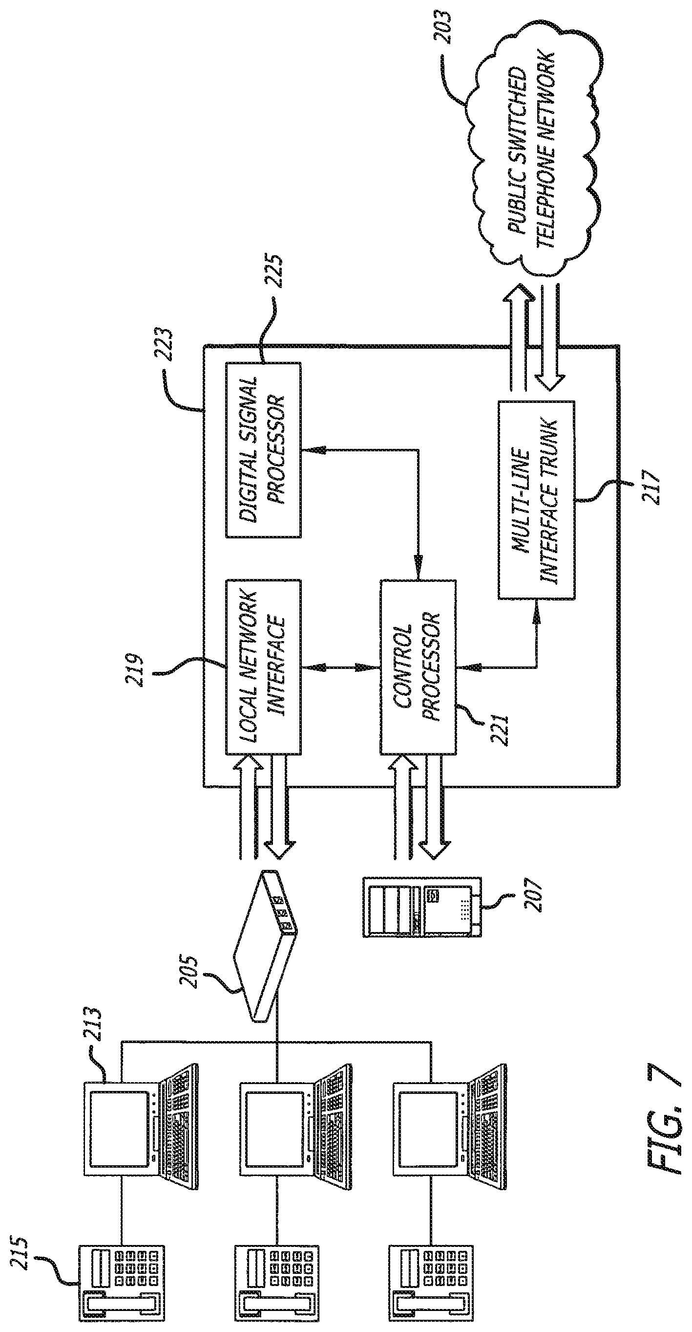
FIG. 7 is a block diagram of a telephonic communication system with a multi-port PSTN module according to an exemplary embodiment of the present invention;
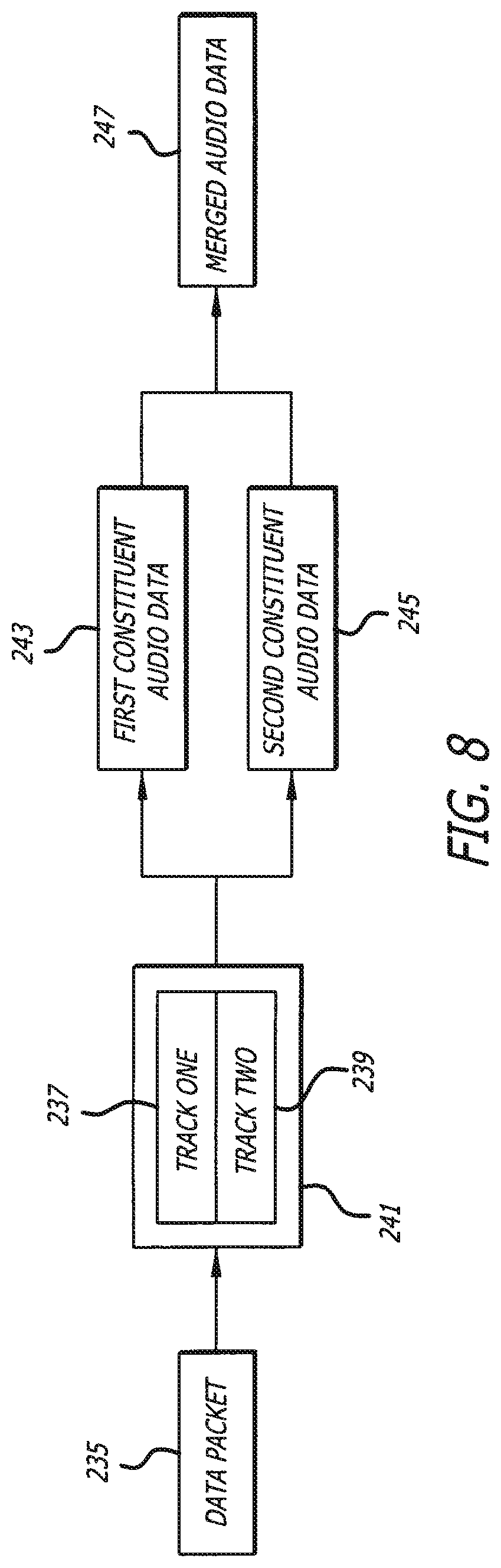
FIG. 8 is a flow chart illustrating the process of recording and separating a telephonic communication in accordance with an exemplary embodiment of the present invention;
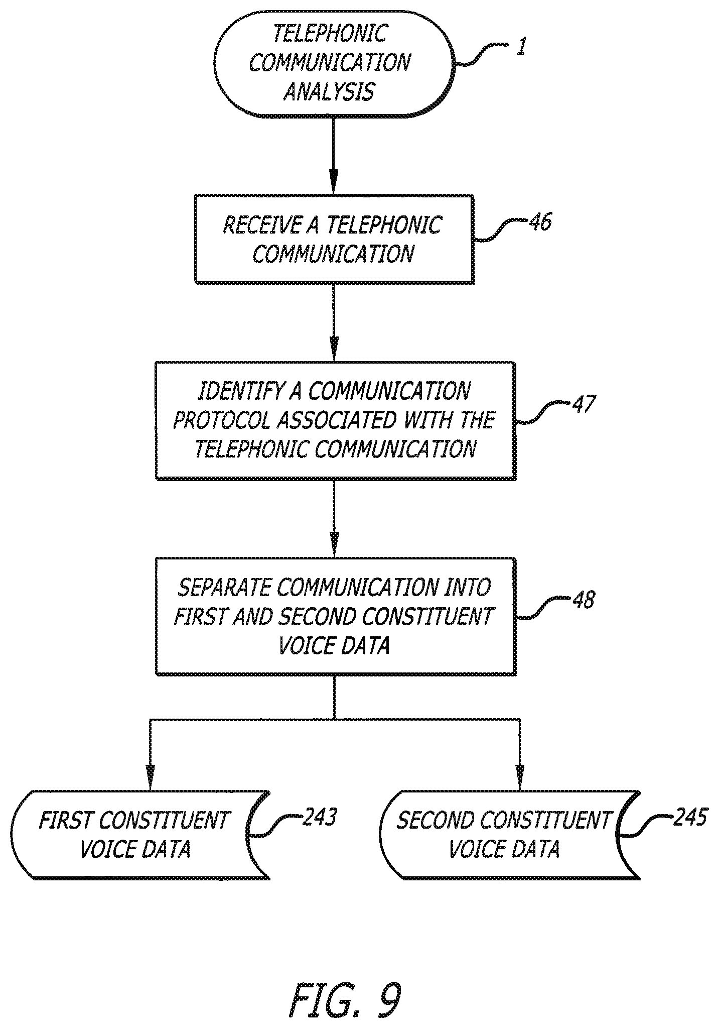
FIG. 9 is a flow chart illustrating the process of recording and separating a telephonic communication in accordance with an exemplary embodiment of the present invention;
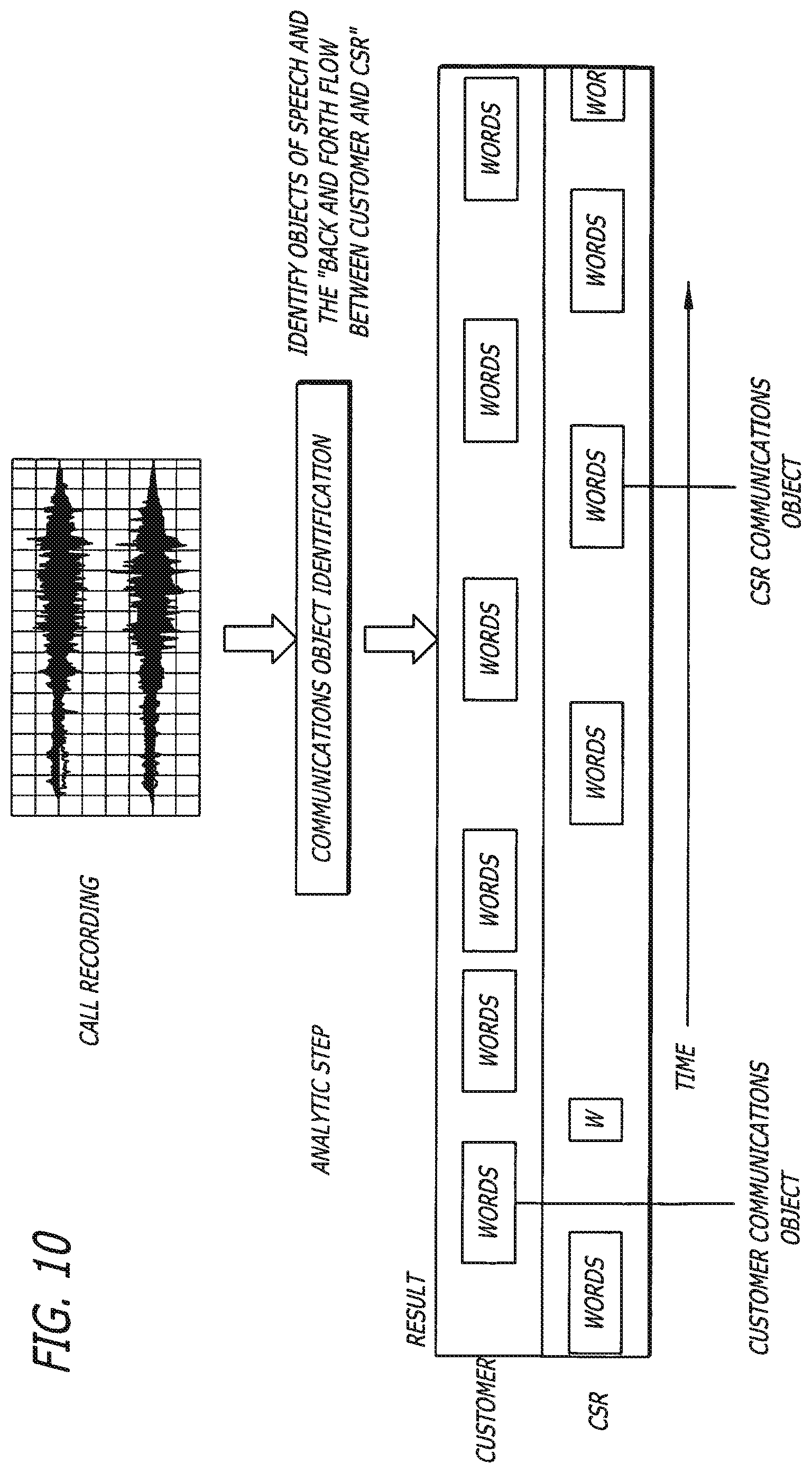
FIG. 10 is a block diagram illustrating customer and CSR communications object identification according to an exemplary embodiment of the present invention;
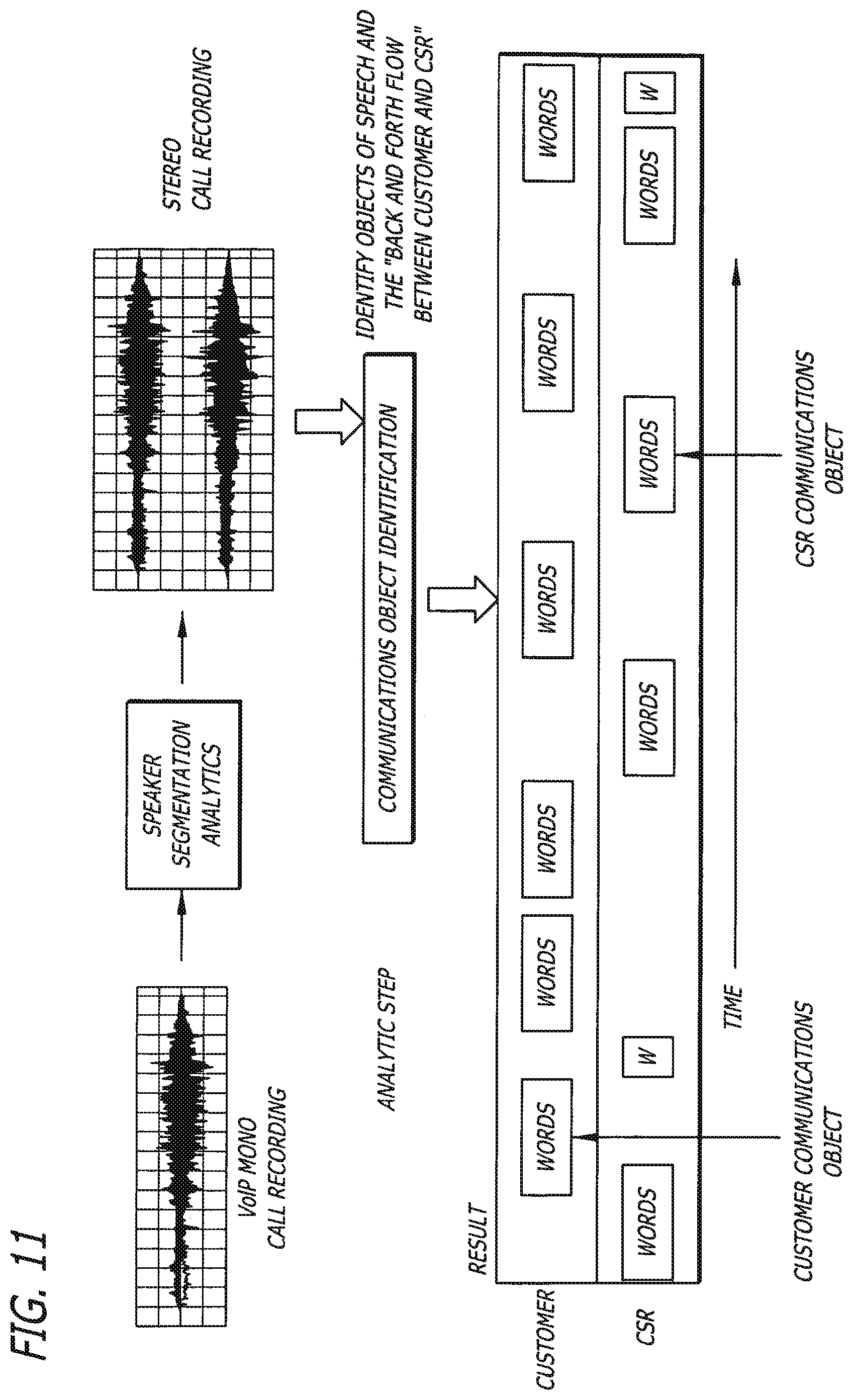
FIG. 11 is block diagram illustrating communications object identification from a VoIP (Voice Over Internet Protocol) mono recording using speaker segmentation analytics to achieve a stereo recording according to an exemplary embodiment of the present invention;
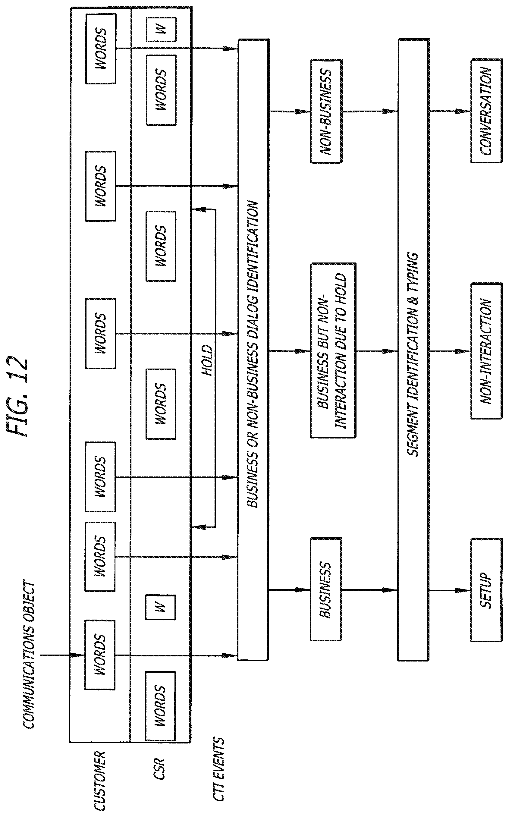
FIG. 12 is a block diagram illustrating classification of communication objects according to an exemplary embodiment of the present invention;
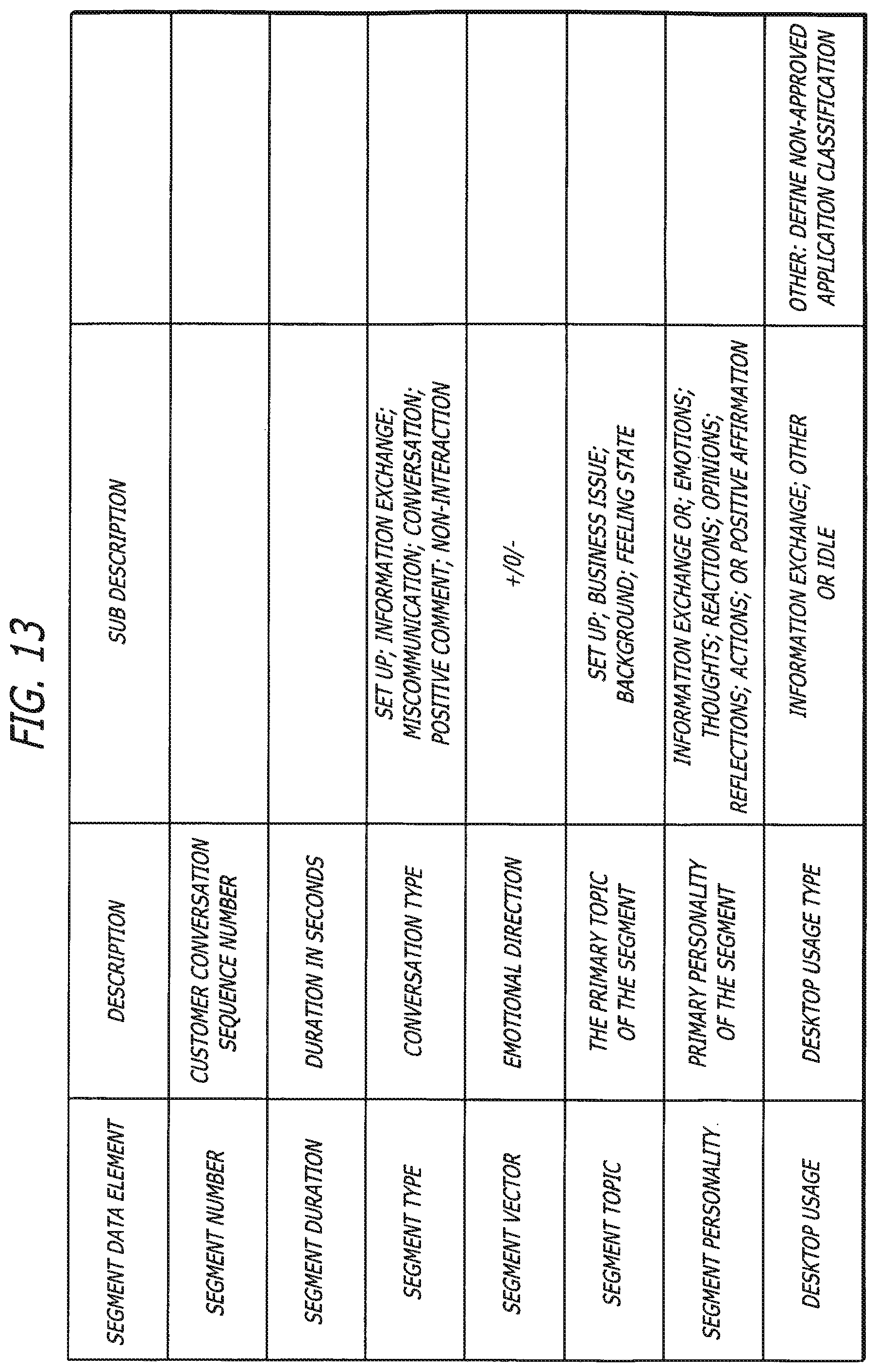
FIG. 13 is a table illustrating a data model according to an exemplary embodiment of the present invention;
FIG. 14 is a segment type data model according to an exemplary embodiment of the present invention;
FIG. 15 is a flow diagram depicting identifying patterns in communication interactions and determining the frequency for each pattern according to an exemplary embodiment of the present invention;
FIGS. 16-18 are flow diagrams illustrating methods for determining which communication interactions are most important, identifying interactions to be focused on, and identifying actions for implementation according to exemplary embodiments of the present invention;
FIG. 19 illustrates a table depicting relevance items that may arise in interactions according to an exemplary embodiment of the present invention;
FIG. 20 is a chart depicting an example of identifying a relevant interaction that relates to a "relationship risk";
FIG. 21 illustrates a flow diagram depicting providing the identified highly relevant interactions to specific areas of a company or organization according to an exemplary embodiment of the present invention;
FIGS. 22-23 are tables that provide exemplary relevance items for a business or organization according to an exemplary embodiment of the present invention;
FIG. 24 is a chart indicating that the significance of each identified relevant interaction may be explained to one or more users according to an exemplary embodiment of the present invention;
FIGS. 25-26 illustrate tables that indicate relevance items, personnel that should be notified of the relevant item, and follow-up actions associated with the relevance items according to an exemplary embodiment of the present invention;
FIG. 27 illustrates an exemplary graphical user interface (GUI) depicting an exemplary telephonic communication and its business relevance according to various relevance items;
FIG. 28 illustrates a GUI depicting the most relevant telephonic communications that represent business relationship risks to a company over a predetermined period of time;
FIG. 29 illustrates a GUI depicting call overview information indicating the occurrence of relevance items in a telephonic communication;
FIG. 30 illustrates a GUI depicting detailed call information, including call issue, call statistics, and call distress moments;
FIG. 31 illustrates a GUI depicting customer details for the call, as well as previous interactions with the customer;
FIG. 32 illustrates a GUI depicting additional customer details, such as the personality type of the customer and how CSRs should respond to such customers given their personality type;
FIG. 33 illustrates a GUI depicting details related to the CSR, including the CSRs past performance related to distress events per call;
FIG. 34 illustrates a GUI depicting recommended actions for the identified relevant call.
DETAILED DESCRIPTION
While this invention is susceptible of embodiments in many different forms, there is shown in the drawings and will herein be described in detail preferred embodiments of the invention with the understanding that the present disclosure is to be considered as an exemplification of the principles of the invention and is not intended to limit the broad aspect of the invention to the embodiments illustrated.
Referring to FIGS. 1-34, a method and system for analyzing an electronic communication between a customer and a contact center is provided. A "contact center" as used herein can include any facility or system server suitable for receiving and recording electronic communications from customers. Such communications can include, for example, telephone calls, facsimile transmissions, e-mails, web interactions, voice over IP ("VoIP") and video. It is contemplated that these communications may be transmitted by and through any type of telecommunication device and over any medium suitable for carrying data. For example, the communications may be transmitted by or through telephone lines, cable or wireless communications. As shown in FIG. 1, the contact center of the present invention is adapted to receive and record varying electronic communications and data formats that represent an interaction that may occur between a customer (or caller) and a contact center agent during fulfillment of a customer and agent transaction.
Process descriptions or blocks in figures should be understood as representing modules, segments, or portions of code which include one or more executable instructions for implementing specific logical functions or steps in the process. Alternate implementations are included within the scope of the embodiments of the present invention in which functions may be executed out of order from that shown or discussed, including substantially concurrently or in reverse order, depending on the functionality involved, as would be understood by those having ordinary skill in the art.
FIG. 2 is a block diagram of a computer or server 12. For purposes of understanding the hardware as described herein, the terms "computer" and "server" have identical meanings and are interchangeably used. Computer 12 includes control system 14. The control system 14 of the invention can be implemented in software (e.g., firmware), hardware, or a combination thereof. The control system 14 may be implemented in software, as an executable program, and is executed by one or more special or general purpose digital computer(s), such as a personal computer (PC; IBM-compatible, Apple-compatible, or otherwise), server computer, personal digital assistant, workstation, minicomputer, or mainframe computer. An example of a general purpose computer that can implement the control system 14 of the present invention is shown in FIG. 2. The control system 14 may reside in, or have portions residing in, any computer such as, but not limited to, a general purpose personal computer. Therefore, computer 12 of FIG. 2 may be representative of any computer in which the control system 14 resides or partially resides.
Generally, in terms of hardware architecture, as shown in FIG. 2, the computer 12 may include a processor 16, memory 18, and one or more input and/or output (I/O) devices 20 (or peripherals) that are communicatively coupled via a local interface 22. The local interface 22 may be, for example, but not limited to, one or more buses or other wired or wireless connections, as is known in the art. The local interface 22 may have additional elements, which are omitted for simplicity, such as controllers, buffers (caches), drivers, repeaters, and receivers, to enable communications. Further, the local interface may include address, control, and/or data connections to enable appropriate communications among the other computer components.
The processor 16 may be a hardware device for executing software, particularly software stored in memory 18. The processor 16 may be any custom made or commercially available processor, a central processing unit (CPU), an auxiliary processor among several processors associated with the computer 12, a semiconductor based microprocessor (in the form of a microchip or chip set), a macroprocessor, or generally any device for executing software instructions. Examples of suitable commercially available microprocessors are as follows: a PA-RISC series microprocessor from Hewlett-Packard Company, an 80.times.8 or Pentium series microprocessor from Intel Corporation, a PowerPC microprocessor from IBM, a Sparc microprocessor from Sun Microsystems, Inc., or a 68xxx series microprocessor from Motorola Corporation.
The memory 18 may include any one or a combination of volatile memory elements (e.g., random access memory (RAM, such as DRAM, SRAM, SDRAM, etc.)) and nonvolatile memory elements (e.g., ROM, hard drive, tape, CDROM, etc.). Moreover, memory 18 may incorporate electronic, magnetic, optical, and/or other types of storage media. The memory 18 may have a distributed architecture where various components are situated remote from one another, but can be accessed by the processor 16.
The software in memory 18 may include one or more separate programs, each of which comprises an ordered listing of executable instructions for implementing logical functions. In the example of FIG. 2, the software in the memory 18 includes the control system 14 in accordance with the present invention and a suitable operating system (O/S) 24. A non-exhaustive list of examples of suitable commercially available operating systems 24 is as follows: (a) a Windows operating system available from Microsoft Corporation; (b) a Netware operating system available from Novell, Inc.; (c) a Macintosh operating system available from Apple Computer, Inc.; (d) a UNIX operating system, which is available for purchase from many vendors, such as the Hewlett-Packard Company, Sun Microsystems, Inc., and AT&T Corporation; (e) a LINUX operating system, which is freeware that is readily available on the Internet; (f) a run time Vxworks operating system from WindRiver Systems, Inc.; or (g) an appliance-based operating system, such as that implemented in handheld computers or personal digital assistants (PDAs) (e.g., PalmOS available from Palm Computing, Inc., and Windows CE available from Microsoft Corporation). The operating system 24 may control the execution of other computer programs, such as the control system 14, and provides scheduling, input-output control, file and data management, memory management, and communication control and related services.
The control system 14 may be a source program, executable program (object code), script, or any other entity comprising a set of instructions to be performed. When a source program, the program needs to be translated via a compiler, assembler, interpreter, or the like, which may or may not be included within the memory 18, so as to operate properly in connection with the O/S 24. Furthermore, the control system 14 may be written as (a) an object oriented programming language, which has classes of data and methods, or (b) a procedure programming language, which has routines, subroutines, and/or functions, for example but not limited to, C, C+F, C# (C Sharp), Pascal, Basic, Fortran, Cobol, Perl, Java, and Ada. The I/O devices 20 may include input devices, for example but not limited to, a keyboard, mouse, scanner, microphone, touch screens, interfaces for various medical devices, bar code readers, stylus, laser readers, radio-frequency device readers, etc. Furthermore, the I/O devices 20 may also include output devices, for example but not limited to, a printer, bar code printers, displays, etc. Finally, the I/O devices 20 may further include devices that communicate both inputs and outputs, for instance but not limited to, a modulator/demodulator (modem; for accessing another device, system, or network), a radio frequency (RF) or other transceiver, a telephonic interface, a bridge, a router, etc.
If the computer 12 is a PC, server, workstation, PDA, or the like, the software in the memory 18 may further include a basic input output system (BIOS) (not shown in FIG. 2). The BIOS is a set of software routines that initialize and test hardware at startup, start the O/S 24, and support the transfer of data among the hardware devices. The BIOS is stored in ROM so that the BIOS can be executed when the computer 12 is activated.
When the computer 12 is in operation, the processor 16 is configured to execute software stored within the memory 18, to communicate data to and from the memory 18, and to generally control operations of the computer 12 pursuant to the software. The control system 14 and the O/S 24, in whole or in part, but typically the latter, are read by the processor 16, perhaps buffered within the processor 16, and then executed.
When the control system 14 is implemented in software, as is shown in FIG. 2, it should be noted that the control system 14 can be stored on any computer readable medium for use by or in connection with any computer related system or method. In the context of this document, a "computer-readable medium" can be any means that can store, communicate, propagate, or transport the program for use by or in connection with the instruction execution system, apparatus, or device. The computer readable medium can be for example, but not limited to, an electronic, magnetic, optical, electromagnetic, infrared, or semiconductor system, apparatus, device, or propagation medium. More specific examples (a non-exhaustive list) of the computer-readable medium would include the following: an electrical connection (electronic) having one or more wires, a portable computer diskette (magnetic), a random access memory (RAM) (electronic), a read-only memory (ROM) (electronic), an erasable programmable read-only memory (EPROM, EEPROM, or Flash memory) (electronic), an optical fiber (optical), and a portable compact disc read-only memory (CDROM) (optical). Note that the computer-readable medium could even be paper or another suitable medium upon which the program is printed, as the program can be electronically captured, via, for instance, optical scanning of the paper or other medium, then compiled, interpreted or otherwise processed in a suitable manner if necessary, and then stored in a computer memory. The control system 14 can be embodied in any computer-readable medium for use by or in connection with an instruction execution system, apparatus, or device, such as a computer based system, processor containing system, or other system that can fetch the instructions from the instruction execution system, apparatus, or device and execute the instructions.
Where the control system 14 is implemented in hardware, the control system 14 may be implemented with any or a combination of the following technologies: a discrete logic circuit(s) having logic gates for implementing logic functions upon data signals, an application specific integrated circuit (ASIC) having appropriate combinational logic gates, a programmable gate array(s) (PGA), a field programmable gate array (FPGA), etc.
The present invention may be implemented in one or more modules using hardware, software, and/or a combination of hardware and software. Specifically, the individual functions of the present invention may be implemented as one or more modules, each module having one or more particular functions and/or purposes to carry out the one or more features of the embodiments of the present invention.
In an exemplary embodiment, the one or more modules may include one or more executable programs or portions of one or more executable programs comprising one or more sets of instructions to be performed by the control system 14. Although the invention is described in terms of a plurality of functions, it should be noted that the individual functions of the embodiments described herein may be implemented in only one or a plurality of modules. A module, therefore, may include one or more functions, as described herein.
FIG. 3 illustrates an uncompressed digital stereo audio waveform of a conversation between a customer and a call center agent that is recorded and separated into customer voice data and call center agent voice data 26. The voice data associated with the audio waveform is then mined and analyzed using multi-stage linguistic and non-linguistic analytic tools 28. The analysis data is stored 30 and can be accessed by a user 31 (e.g., CSR supervisor) through an interface portal 32 for subsequent review 32. The digital stereo audio waveform is compressed 34 and stored 36 in an audio file which is held on a media server 38 for subsequent access through the interface portal 32.
The method of the present invention is configured to postpone audio compression until analysis of the audio data is complete. This delay allows the system to apply the analytic tools to a truer and clearer hi-fidelity signal. The system employed in connection with the present invention also minimizes audio distortion, increases fidelity, eliminates gain control and requires no additional filtering of the signal.
As shown in FIG. 4, the method of the present invention more specifically comprises the step of separating a telephonic communication 2 into first constituent voice data and second constituent voice data 40. One of the first or second constituent voice data may then be separately analyzed at step 42. At step 44, the first and/or second voice data may be analyzed to determine relevant portions of the voice data relative to other telephonic communications. This may enable a business or organization to determine the most relevant interactions to focus on.
The telephonic communication 2 being analyzed may be one of numerous calls stored within a contact center server 12, or communicated to a contact center during a given time period. Accordingly, the present method contemplates that the telephonic communication 2 being subjected to analysis is selected from the plurality of telephonic communications. The selection criteria for determining which communication to analyze may vary. For example, the communications coming into a contact center can be automatically categorized into a plurality of call types using an appropriate algorithm. For example, the system may employ a word-spotting algorithm that categorizes communications 2 into particular types or categories based on words used in the communication. In one embodiment, each communication 2 is automatically categorized as a service call type (e.g., a caller requesting assistance for servicing a previously purchased product), a retention call type (e.g., a caller expressing indignation, or having a significant life change event), or a sales call type (e.g., a caller purchasing an item offered by a seller). In one scenario, it may be desirable to analyze all of the "sales call type" communications received by a contact center during a predetermined time frame.
Alternatively, the communications 2 may be grouped according to customer categories, and the user may desire to analyze the communications 2 between the call center and communicants within a particular customer category. For example, it may be desirable for a user to perform an analysis only of a "platinum customers" category, consisting of high end investors, or a "high volume distributors" category comprised of a user's best distributors.
In one embodiment the telephonic communication 2 is a telephone call in which a telephonic signal is transmitted. As many be seen in FIGS. 5 and 6, a customer sending a telephonic signal may access a contact center 10 through the public switched telephone network (PSTN) 203 and an automatic call distribution system (PBX/ACD) 205 directs the communication to one of a plurality of agent work stations 211, 213. Each agent work station 211, 213 may include, for example, a computer 215 and a telephone 213.
When analyzing voice data, it is preferable to work from a true and clear hi-fidelity signal. This is true both in instances in which the voice data is being translated into a text format for analysis, or in instance in which an analysis model is being applied directly to an audio waveform, audio stream or file containing voice data.
FIG. 5 illustrates a telephonic communication system 201, such as a distributed private branch exchange (PBX), having a public switched telephone network (PSTN) 203 connected to the PBX through a PBX switch 205.
The PBX switch 205 may provide an interface between the PSTN 203 and a local network. The interface may be controlled by software stored on a telephony server 207 coupled to the PBX switch 205. The PBX switch 205, using interface software, may connect trunk and line station interfaces of the public switch telephone network 203 to stations of a local network or other peripheral devices contemplated by one skilled in the art. The PBX switch may be integrated within telephony server 207. The stations may include various types of communication devices connected to the network, including the telephony server 207, a recording server 209, telephone stations 211, and client personal computers 213 equipped with telephone stations 215. The local network may further include fax machines and modems.
Generally, in terms of hardware architecture, the telephony server 207 may include a processor, memory, and one or more input and/or output (I/O) devices (or peripherals) that are communicatively coupled via a local interface. The processor may be any custom-made or commercially available processor, a central processing unit (CPU), an auxiliary processor among several processors associated with the telephony server 207, a semiconductor based microprocessor (in the form of a microchip or chip set), a macroprocessor, or generally any device for executing software instructions. The memory of the telephony server 207 may include any one or a combination of volatile memory elements (e.g., random access memory (RAM, such as DRAM, SRAM, SDRAM, etc.)) and nonvolatile memory elements (e.g., ROM, hard drive, tape, CDROM, etc.). The telephony server 207 may further include a keyboard and a mouse for control purposes, and an attached graphic monitor for observation of software operation.
The telephony server 207 may incorporate PBX control software to control the initiation and termination of connections between stations and via outside trunk connections to the PSTN 203. In addition, the software may monitor the status of all telephone stations 211 in real-time on the network and may be capable of responding to telephony events to provide traditional telephone service. This may include the control and generation of the conventional signaling tones such as dial tones, busy tones, ring back tones, as well as the connection and termination of media streams between telephones on the local network. Further, the PBX control software may use a multi-port module 223 and PCs to implement standard PBX functions such as the initiation and termination of telephone calls, either across the network or to outside trunk lines, the ability to put calls on hold, to transfer, park and pick up calls, to conference multiple callers, and to provide caller ID information. Telephony applications such as voice mail and auto attendant may be implemented by application software using the PBX as a network telephony services provider.
Referring to FIG. 7, the telephony server 207 may be equipped with multi-port PSTN module 223 having circuitry and software to implement a trunk interface 217 and a local network interface 219. The PSTN module 223 may comprise a control processor 221 to manage the transmission and reception of network messages between the PBX switch 205 and the telephony network server 207. The control processor 221 also may be capable of directing network messages between the PBX switch 205, the local network interface 291, the telephony network server 207, and the trunk interface 217. The local network may use Transmission Control Protocol/Internet Protocol (TCP/IP). The network messages may contain computer data, telephony transmission supervision, signaling and various media streams, such as audio data and video data. The control processor 221 may direct network messages containing computer data from the PBX switch 205 to the telephony network server 207 directly through the multi-port PSTN module 223.
The control processor 221 may include buffer storage and control logic to convert media streams from one format to another, if necessary, between the trunk interface 217 and local network. The trunk interface 217 provides interconnection with the trunk circuits of the PSTN 203. The local network interface 219 provides conventional software and circuitry to enable the telephony server 207 to access the local network. The buffer RAM and control logic implement efficient transfer of media streams between the trunk interface 217, the telephony server 207, the digital signal processor 225, and the local network interface 219.
The trunk interface 217 utilizes conventional telephony trunk transmission supervision and signaling protocols required to interface with the outside trunk circuits from the PSTN 203. The trunk lines carry various types of telephony signals such as transmission supervision and signaling, audio, fax, or modem data to provide plain old telephone service (POTS). In addition, the trunk lines may carry other communication formats such T1, ISDN or fiber service to provide telephony or multimedia data images, video, text or audio.
The control processor 221 may manage real-time telephony event handling pertaining to the telephone trunk line interfaces, including managing the efficient use of digital signal processor resources for the detection of caller ID, DTMF, call progress and other conventional forms of signaling found on trunk lines. The control processor 221 also may manage the generation of telephony tones for dialing and other purposes, and controls the connection state, impedance matching, and echo cancellation of individual trunk line interfaces on the multi-port PSTN module 223.
Preferably, conventional PBX signaling is utilized between trunk and station, or station and station, such that data is translated into network messages that convey information relating to real-time telephony events on the network, or instructions to the network adapters of the stations to generate the appropriate signals and behavior to support normal voice communication, or instructions to connect voice media streams using standard connections and signaling protocols. Network messages are sent from the control processor 221 to the telephony server 207 to notify the PBX software in the telephony server 207 of real-time telephony events on the attached trunk lines. Network messages are received from the PBX Switch 205 to implement telephone call supervision and may control the set-up and elimination of media streams for voice transmission.
The local network interface 219 may include conventional circuitry to interface with the local network. The specific circuitry may be dependent on the signal protocol utilized in the local network. The local network may be a local area network (LAN) utilizing IP telephony. IP telephony integrates audio and video stream control with legacy telephony functions and may be supported through the H.323 protocol. H.323 is an International Telecommunication Union-Telecommunications protocol used to provide voice and video services over data networks. H.323 permits users to make point-to-point audio and video phone calls over a local area network. IP telephony systems can be integrated with the public telephone system through a local network interface 219, such as an IP/PBX-PSTN gateway, thereby allowing a user to place telephone calls from an enabled computer. For example, a call from an IP telephony client to a conventional telephone would be routed on the LAN to the IP/PBX-PSTN gateway. The IP/PBX-PSTN gateway translates H.323 protocol to conventional telephone protocol and routes the call over the conventional telephone network to its destination. Conversely, an incoming call from the PSTN 203 is routed to the IP/PBX-PSTN gateway and translates the conventional telephone protocol to H.323 protocol.
As noted above, PBX trunk control messages are transmitted from the telephony server 207 to the control processor 221 of the multi-port PSTN. In contrast, network messages containing media streams of digital representations of real-time voice are transmitted between the trunk interface 217 and local network interface 219 using the digital signal processor 225. The digital signal processor 225 may include buffer storage and control logic. Preferably, the buffer storage and control logic implement a first-in-first-out (FIFO) data buffering scheme for transmitting digital representations of voice audio between the local network to the trunk interface 217. It is noted that the digital signal processor 225 may be integrated with the control processor 221 on a single microprocessor.
The digital signal processor 225 may include a coder/decoder (CODEC) connected to the control processor 221. The CODEC may be a type TCM29c13 integrated circuit made by Texas Instruments, Inc. For example, the digital signal processor 225 may receive an analog or digital voice signal from a station within the network or from the trunk lines of the PSTN 203. The CODEC converts the analog voice signal into in a digital from, such as digital data packets. It should be noted that the CODEC is not used when connection is made to digital lines and devices. From the CODEC, the digital data is transmitted to the digital signal processor 225 where telephone functions take place. The digital data is then passed to the control processor 221 which accumulates the data bytes from the digital signal processor 225. It is preferred that the data bytes are stored in a first-in-first-out (FIFO) memory buffer until there is sufficient data for one data packet to be sent according to the particular network protocol of the local network. The specific number of bytes transmitted per data packet depends on network latency requirements as selected by one of ordinary skill in the art. Once a data packet is created, the data packet is sent to the appropriate destination on the local network through the local network interface 219. Among other information, the data packet may contain a source address, a destination address, and audio data. The source address identifies the location the audio data originated from and the destination address identifies the location the audio data is to be sent.
The system may enable bi-directional communication by implementing a return path allowing data from the local network, through the local network interface 219, to be sent to the PSTN 203 through the multi-line PSTN trunk interface 217. Data streams from the local network are received by the local network interface 219 and translated from the protocol utilized on the local network to the protocol utilized on the PSTN 203. The conversion of data may be performed as the inverse operation of the conversion described above relating to the IP/PBX-PSTN gateway. The data stream may be restored in appropriate form suitable for transmission through to either a connected telephone 211, 215 or an interface trunk 217 of the PSTN module 223, or a digital interface such as a T1 line or ISDN. In addition, digital data may be converted to analog data for transmission over the PSTN 203.
Generally, the PBX switch of the present invention may be implemented with hardware or virtually. A hardware PBX has equipment located local to the user of the PBX system. The PBX switch 205 utilized may be a standard PBX manufactured by Avaya, Siemens AG, NEC, Nortel, Toshiba, Fujitsu, Vodavi, Mitel, Ericsson, Panasonic, or InterTel. In contrast, a virtual PBX has equipment located at a central telephone service provider and delivers the PBX as a service over the PSTN 203.
Turning again to FIG. 5, the system may include a recording server 209 for recording and separating network messages transmitted within the system. The recording server 209 may be connected to a port on the local network, as seen in FIG. 5. Alternatively, the recording server 209 may be connected to the PSTN trunk line. The recording server 209 may include control system software, such as recording software. The recording software of the invention may be implemented in software (e.g., firmware), hardware, or a combination thereof. The recording software may be implemented in software as an executable program, and is executed by one or more special or general purpose digital computer(s), such as a personal computer (PC; IBM-compatible, Apple-compatible, or otherwise), server, personal digital assistant, workstation, minicomputer, or mainframe computer. An example of a general purpose computer that can implement the recording software of the present invention is shown in FIG. 2. The recording software may reside in, or have portions residing in, any computer such as, but not limited to, a general purpose personal computer. Therefore, recording server 209 of FIG. 5 may be representative of any type of computer in which the recording software resides or partially resides.
Generally, hardware architecture may be the same as that discussed above and shown in FIG. 2. Specifically, the recording server 209 includes a processor, memory, and one or more input and/or output (I/O) devices (or peripherals) that are communicatively coupled via a local interface as previously described. The local interface can be, for example, but not limited to, one or more buses or other wired or wireless connections. The local interface may have additional elements, which are omitted for simplicity, such as controllers, buffers (caches), drivers, repeaters, and receivers, to enable communications. Further, the local interface may include address, control, and/or data connections to enable appropriate communications among the other computer components.
As noted above, the recording server 209 incorporates recording software for recording and separating a signal based on the source address and/or destination address of the signal. The method utilized by the recording server 209 depends on the communication protocol utilized on the communication lines to which the recording server 209 is coupled. In the communication system contemplated by the present invention, the signal carrying audio data of a communication between at least two users may be an analog signal or a digital signal in the form of a network message. In one embodiment, the signal is an audio data transmitted according to a signaling protocol, for example the H.323 protocol described above.
An example of a communication between an outside caller and a call center agent utilizing the present system 200 is illustrated in FIG. 7 and described herein. In the embodiment of FIG. 7, when an outside caller reaches the system through the multi-line interface trunk 217, their voice signal may be digitized (if needed) in the manner described above, and converted into digital data packets 235 (as illustrated in FIG. 8) according to the communication protocol utilized on the local network of the system. The data packet 235 may comprise a source address identifying the address of the outside caller, a destination address identifying the address of the call center agent, and first constituent audio data comprising at least a portion of the outside caller's voice. The data packet 235 may further comprise routing data identifying how the data packet 235 should be routed through the system and other relevant data. Once the data packet 235 is created, the data packet 235 may be sent to the appropriate destination on the local network, such as to a call center agent, through the local network interface 219. The PBX and/or an automatic call distributor (ACD) 205 may determine the initial communication setup, such as the connection state, impedance matching, and echo cancellation, according to predetermined criteria.
Similar to the process described above, when the call center agent speaks, their voice is digitized (if needed) and converted into digital data packet 235 according to the communication protocol utilized on the local network. The data packet 235 comprises a source address identifying the address of the call center agent, a destination address identifying the address of the outside caller, and second constituent audio data comprising at least a portion of the call center agent's voice. The data packet 235 is received by the local network interface 219 and translated from the communication protocol utilized on the local network to the communication protocol utilized on the PSTN 203. The conversion of data can be performed as described above. The data packet 235 is restored in appropriate form suitable for transmission through to either a connected telephone 211 (illustrated in FIGS. 5 and/or 6), 215 or a interface trunk 217 of the PSTN module 223, or a digital interface such as a T1 line or ISDN. In addition, digital data may be converted to analog data for transmission through the PSTN 203.
The recording server 209 (as shown in FIGS. 5 and/or 6) may receive a data packet 235 comprising: the source address identifying the address of the outside caller, a destination address identifying the address of the call center agent, and the first constituent audio data comprising at least a portion of the outside callers voice. The recording server 209 may alternatively receive a data packet 235 comprising a source address identifying the address of the call center agent, a destination address identifying the address of the outside caller, and second constituent audio data comprising at least a portion of the customer's agent voice. It is understood by one of ordinary skill in the art that the recording server 209 is programmed to identify the communication protocol utilized by the local network and extract the audio data within the data packet 235. In one embodiment, the recording server 209 can automatically identify the utilized communication protocol from a plurality of communication protocols. The plurality of communication protocols can be stored in local memory or accessed from a remote database.
The recording server 209 may comprise recording software to record the communication session between the outside caller and the call center agent in a single data file in a stereo format. Now referring to FIG. 8, the first data file 241 has at least a first audio track 237 and a second audio track 239. Once a telephone connection is established between an outside caller and a call center agent, the recording software may create a first data file 241 to record the communication between the outside caller and the call center agent. It is contemplated that the entire communication session or a portion of the communication session can be recorded.
Upon receiving the data packet 235, the recording server 209 determines whether to record the audio data contained in the data packet 235 in either the first audio track 237 or the second audio track 239 of the first data file 241 as determined by the source address, destination address, and/or the audio data contained within the received data packet 235. Alternatively, two first data files can be created, wherein the first audio track is recorded to the one of the first data file and the second audio track is recorded to the second first data file. In one embodiment, if the data packet 235 comprises a source address identifying the address of the outside caller, a destination address identifying the address of the call center agent, and first constituent audio data, the first constituent audio data is recorded on the first audio track 237 of the first data file 241. Similarly, if the data packet 235 comprises a source address identifying the address of the call center agent, a destination address identifying the address of the outside caller, and second constituent audio data, the second constituent audio data is recorded on the second audio track 239 of the first data file 241. It should be noted the first and second constituent audio data can be a digital or analog audio waveform or a textual translation of the digital or analog waveform. The recording process may be repeated until the communication link between the outside caller and call center agent is terminated.
As noted above, the recording server 209 may be connected to the trunk lines of the PSTN 203 as seen in FIG. 6. The PSTN 203 may utilize a different protocol and therefore, the recording server 209 is configured to identify the communication protocol utilized by the PSTN 203, recognize the source and destination address of a signal and extract the audio data from the PSTN 203.
As shown in FIG. 8, once the communication link is terminated, the recording server 209 ends the recording session and stores the single data file having the recorded communication session in memory. After the first data file is stored in memory, the recording server 209 may extract either or both of the first constituent audio data from the first audio track of the first data file or the second constituent audio data from the second audio track of the first data file. In one embodiment, the first constituent audio data extracted from the first audio track is stored in a first constituent data file 243. Similarly, the second constituent audio data extracted from the second audio track may be stored in a second constituent data file 245. The first and second constituent data files 243, 245 can be compressed before being stored in memory. The extracted data can be in the form of a digital or analog audio waveform or can be a textual translation of the first or second constituent audio data. It is contemplated that either or both of the first constituent data file 243 or the second constituent data file 245 can be further analyzed or processed. For example, among other processes and analyses, filtering techniques can be applied to the first constituent data file and/or the second constituent data file. Moreover, event data, such as silence periods or over-talking, may be identified through analysis techniques known to those skilled in the art.
Further, as illustrated in FIG. 8, the first constituent data file 243 and second constituent data file 245 may be merged together into a single second data file 247. The first and second constituent data files may be merged in a stereo format where the first constituent audio data from the first constituent data file 243 is stored on a first audio track of the second data file 247 and the second constituent audio data from the second constituent data file 245 is stored on a second audio track of the second data file 247. Alternatively, the first and second constituent data files may be merged in a mono format where the first constituent audio data from the first constituent data file 243 and the second constituent audio data from the second constituent data file 245 are stored on a first audio track of the second data file 247. Additionally, the first and second constituent audio data may be merged into a document having a textual translation of the audio data. In such a case, identifiers may be associated with each of the merged first and second constituent audio data in order to associate the merged first constituent audio data with the outside caller, and associate the merged second constituent audio data with the call center agent. The second data file 247 may be compressed before being stored in memory.
It is known in the art that "cradle-to-grave" recording may be used to record all information related to a particular telephone call from the time the call enters the contact center to the later of: the caller hanging up or the agent completing the transaction. All of the interactions during the call are recorded, including interaction with an IVR system, time spent on hold, data keyed through the caller's key pad, conversations with the agent, and screens displayed by the agent at his/her station during the transaction.
As shown in FIGS. 10-12, once the first and second constituent voice data are separated one from the other, each of the first and second constituent voice data can be independently mined and analyzed. It will be understood that "mining" as referenced herein is to be considered part of the process of analyzing the constituent voice data. It is also contemplated by the present invention that the mining and behavioral analysis be conducted on either or both of the constituent voice data.
Even with conventional audio mining technology, application of analysis models directly to an audio file can be very difficult. In particular, disparities in dialect, phonemes, accents and inflections can impede or render burdensome accurate identification of words. And while it is contemplated by the present invention that mining and analysis in accordance with the present invention can be applied directly to voice data configured in audio format, in a preferred embodiment of the present invention, the voice data to be mined and analyzed is first translated into a text file. It will be understood by those of skill that the translation of audio to text and subsequent data mining may be accomplished by systems known in the art. For example, the method of the present invention may employ software such as that sold under the brand name Audio Mining SDK by Scansoft, Inc., or any other audio mining software suitable for such applications. As shown in FIGS. 10-12, the separated voice data is used to form communication objects which may be typed (i.e., classified) into categories such as setup, information exchange, miscommunication, non-interaction, conversation, or positive comment. In particular, the method of the present invention searches for and identifies text-based keywords relevant to each of the predefined type categories. The typed communication objects may then be further categorized to form segments of objects according to type.
FIG. 10 illustrates a stereo call recording with voice data for a customer and a CSR. The voice data from the stereo recording is converted to text. Accordingly, there is separate text data for the customer communication and the CSR communication. Objects may be identified and typed (i.e., classified) within the text. Alternatively, as illustrated in FIG. 11, a mono (rather than stereo) call recording that may be from a VoIP (Voice Over Internet Protocol) may be used to form the stereo recording of the customer and the CSR using speaker segmentation analytics. Upon formation of the stereo recording, the communications objects of the customer and the CSR may be identified and typed (i.e., classified).
FIG. 12 illustrates the words of the CSR and customer as communications objects, as well as CTI (Computer Telephony Integration) events (e.g., a "hold" event). The communications objects may be typed (i.e., classified) as business related communications objects or as non-business (e.g., conversation) related communication objects. Objects may be further classified as non-interaction objects that are business related. For example, the CSR may place the customer on hold in order to speak with another CSR regarding the customer's situation.
Upon classification of the customer and CSR communication objects, segments of like objects may be formed. For example, communications objects may be combined to form segments related to call setup, information exchange, non-interaction, conversation, or positive comment.
FIG. 13 illustrates a table which indicates segment data elements. For example, segments may have a segment number which corresponds to their sequence number order of appearance in a telephonic communication. Segments may also have a duration of time associated with them, as well as an emotional vector that indicates the emotional direction of the customer (e.g., positive, negative, or neutral). Segments may also be identified with a primary topic. The personality of the segment may also be identified. For example, the personality may relate to information exchange (i.e., business-related communications) or may be classified by a personality type (e.g., emotions, thoughts, reflections, actions, or positive affirmation). The software application used during the same time period of the segment may also be affiliated with a segment. For example, a business application may be in use during the communications segment that relates to information exchange.
FIG. 14 illustrates a table indicating various exemplary types (i.e., classifications) of segments, such as setup, information exchange, miscommunication, non-interaction, conversation, and positive comment. FIG. 14 also illustrates that a segment vector (e.g., emotional direction) may be associated with a segment type. For example, setup and information exchange may have neutral ("0") vectors. Miscommunication segments and non-interaction segments may have negative ("-") vectors, as these segments may be considered unfavorable portions of a telephonic communication between a customer and a CSR. Conversation segments, which may be non-business related, may have a positive vector ("+"), as these segments may be perceived favorably by customers during a telephonic communication with a CSR. Positive comment segments (e.g., where a customer compliments a CSR) may have an increased positive vector ("++").
According to one embodiment of the present invention, a psychological behavioral model may also be used to analyze the voice data, and may be, for example, the Process Communication Model ("PCM") developed by Dr. Taibi Kahler. PCM is a psychological behavioral analytic tool which presupposes that all people fall primarily into one of six basic personality types: Reactor, Workaholic, Persister, Dreamer, Rebel and Promoter. Although each person is one of these six types, all people have parts of all six types within them arranged like a six-tier configuration. Each of the six types learns differently, is motivated differently, communicates differently, and has a different sequence of negative behaviors they engage in when they are in distress. Importantly, according to PCM, each personality type of PCM responds positively or negatively to communications that include tones or messages commonly associated with another of the PCM personality types. Thus, an understanding of a communicant's PCM personality type offers guidance as to an appropriate responsive tone or message or wording.
According to the PCM Model the following behavioral characteristics are associated with the respective personality types. Reactors: compassionate, sensitive, and warm; great "people skills" and enjoy working with groups of people. Workaholics: responsible, logical, and organized. Persisters: conscientious, dedicated, and observant; tend to follow the rules and expect others to follow them. Dreamers: reflective, imaginative, and calm. Rebels: creative, spontaneous, and playful. Promoters: resourceful, adaptable, and charming.
These behavioral characteristics may be categorized by words, tones, gestures, postures and facial expressions, and can be observed objectively with significantly high interjudge reliability.
Significant words may be mined within one or both of the separated first and second constituent voice data, and applies PCM to the identified words. For example, the following behavioral signifiers (i.e., words) may be associated with the corresponding behavioral type in the PCM Model TYPE BEHAVIORAL SIGNIFIERS: Reactors--Emotional Words; Workaholics--Thought Words; Persisters--Opinion Words; Dreamers--Reflection Words; Rebels--Reaction Words; Promoters--Action Words.
When a behavioral signifier is identified within the voice data, the identified behavioral signifier is executed against a system database which maintains all of the data related to the psychological behavioral model. Based on the behavioral signifiers identified in the analyzed voice data, a predetermined algorithm is used to decipher a linguistic pattern that corresponds to one or more of the PCM personality types. More specifically, the method mines for linguistic indicators (words and phrases) that reveal the underlying personality characteristics of the speaker during periods of distress. Non-linguistic indicators may also be identified to augment or confirm the selection of a style for each segment of speech. Looking at all the speech segments in conjunction with personality information the software determines an order of personality components for the caller by weighing a number of factors such as timing, position, quantity and interaction between the parties in the dialog.
The resultant behavioral assessment data is stored in a database so that it may subsequently be used to comparatively analyze against behavioral assessment data derived from analysis of the other of the first and second constituent voice data. The software considers the speech segment patterns of all parties in the dialog as a whole to refine the behavioral and distress assessment data of each party, making sure that the final distress and behavioral results are consistent with patterns that occur in human interaction. Alternatively, the raw behavioral assessment data derived from the analysis of the single voice data may be used to evaluate qualities of a single communicant (e.g., the customer or agent behavioral type, etc.). The results generated by analyzing voice data through application of a psychological behavioral model to one or both of the first and second constituent voice data can be graphically illustrated as discussed in further detail below.
It should be noted that, although one preferred embodiment of the present invention uses PCM as a linguistic-based psychological behavioral model, it is contemplated that any known linguistic-based psychological behavioral model be employed without departing from the present invention. It is also contemplated that more than one linguistic-based psychological behavioral model be used to analyze one or both of the first and second constituent voice data.
In addition to the behavioral assessment of voice data, the method of the present invention may also employ distress analysis to voice data. Linguistic-based distress analysis is preferably conducted on both the textual translation of the voice data and the audio file containing voice data. Accordingly, linguistic-based analytic tools as well as non-linguistic analytic tools may be applied to the audio file. For example, one of skill in the art may apply spectral analysis to the audio file voice data while applying a word spotting analytical tool to the text file. Linguistic-based word spotting analysis and algorithms for identifying distress can be applied to the textual translation of the communication. Preferably, the resultant distress data is stored in a database for subsequent analysis of the communication.
FIG. 15 is a flow diagram depicting identifying patterns in communication interactions and determining the frequency for each pattern according to an exemplary embodiment of the present invention. As illustrated in the exemplary flow, information may be gathered (e.g., from voice communications between a CSR and a customer as described above, etc.). The gathered information may be interpreted, based on a set of predetermined rules or other suitable criteria. Such analysis may provide pattern matching capability, such that like objects or segments of information may be categorized into segments. Upon performing pattern analysis, the frequency of patterns appearing in telephonic communication may be ascertained. The categorization and typing analysis may allow a business or organization to determine the "outlier" or communications that are the most relevant to the business or organization, and enable the business to follow up or take action in connection with the identified calls. The call type and pattern analysis may also enable the system to direct particular exemplary calls to particular parts of an organization or business for additional review or action.
FIGS. 16-18 are flow diagrams illustrating methods for determining which communication interactions are most important, identifying interactions to be focused on, and identifying actions for implementation. As illustrated in FIG. 16, interactions between one or more customers and an organization or business may be made via a variety of different communication systems (e.g., the Web pages, IVR systems, with CSRs at call centers, databases, etc.). The systems and methods described herein determine which interactions are the most important to the function of business or organization. These business or organization functions may be predefined by a system administrator or other suitable entity. Businesses and organizations may have a given capacity to address communication activities with customers, as well as address the business and organizational functions. Thus, it is desirable to identify which interactions between a customer and a business or organization should be focused on. The systems and methods described herein may enable the identification of action for implementation by a business or organization, based on the selected interactions to focus on.
FIG. 17 depicts a flow diagram illustrating an exemplary method of call type analysis and pattern analysis. The method may interpret the pattern of selected interactions or substantially all interactions (e.g., between a customer and a CSR, etc.). The most important interactions may be identified (e.g., based on a set of predetermined rules) for some parts or each part of a business organization (e.g., contact center, product development, sales, etc.). The systems and methods described herein may provide "relevant interactions" to parts or to each part of the business or organization. These relevant interactions may be accompanied by specific actions for the part of the business or organization to take.
FIG. 18 depicts a flow diagram illustrating the application of behavioral analysis (as described herein) in order to determine the most relevant items of communications to a business or organization. A set of interaction outcomes (i.e., relevance items, for example, as identified in FIG. 19) may be determined that have been identified as being meaningful to one or more parts of a business or organization. Behavioral analysis may be applied to the set of interactions. Behavioral analysis may be a predefined set of rules to identify the most relevant interactions based on the applied rules. The identified relevant interactions may be directed to one or more portions of an organization for review and/or further action. Additionally, an interactive vignette (e.g., an audio-visual presentation) may accompany the identified relevant interactions in order to explain the business or organizational significance of each interaction, as well as provide one or more recommended follow-up actions.
FIG. 20 illustrates an example of determining a relevant interaction. Given 10,000 interactions, the interactions having a significant "relationship risk" may be identified. Upon starting with the initial 10,000 interactions, 9,500 interactions may be discounted,
D00000
D00001
D00002
D00003
D00004
D00005
D00006
D00007
D00008
D00009
D00010
D00011
D00012
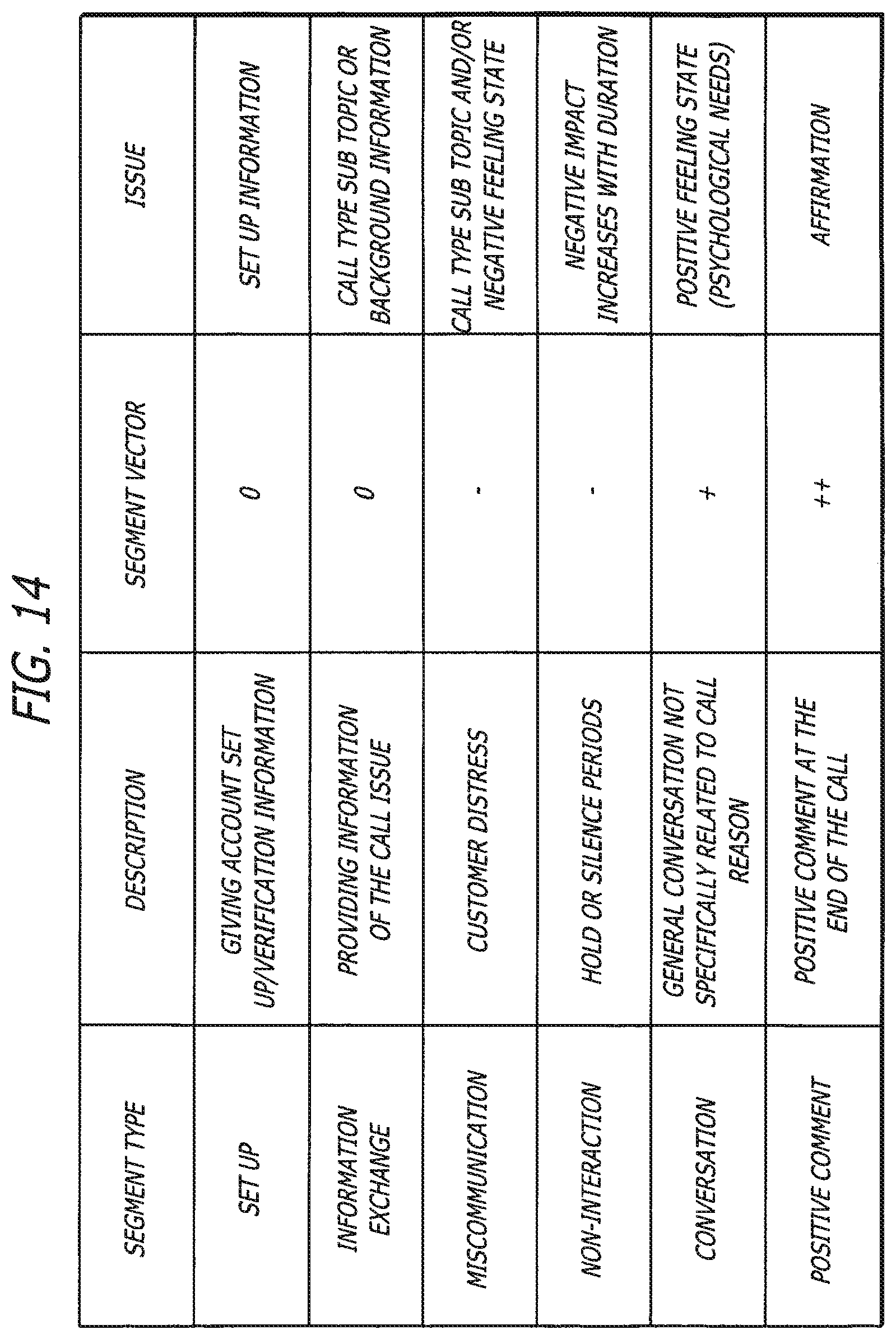
D00013

D00014
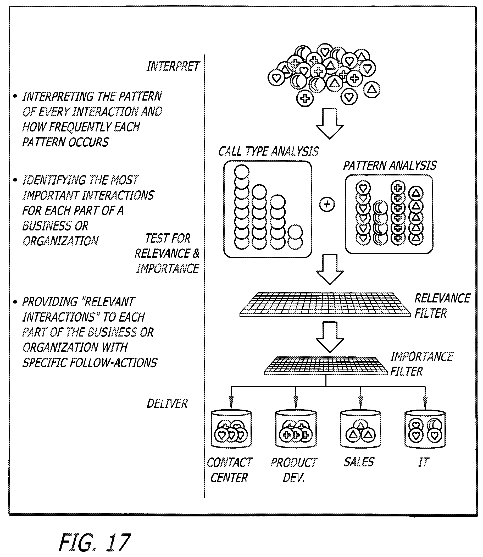
D00015
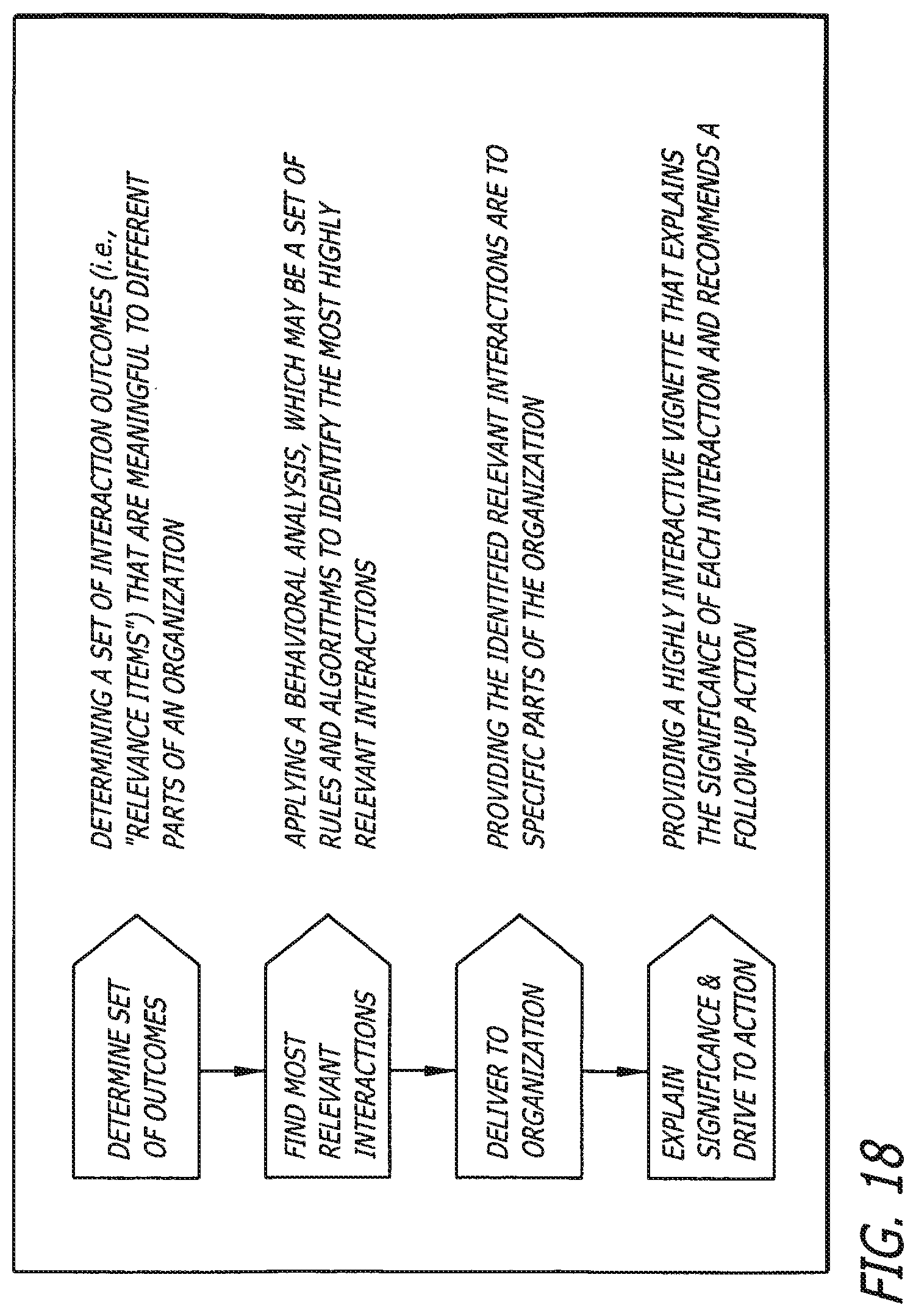
D00016
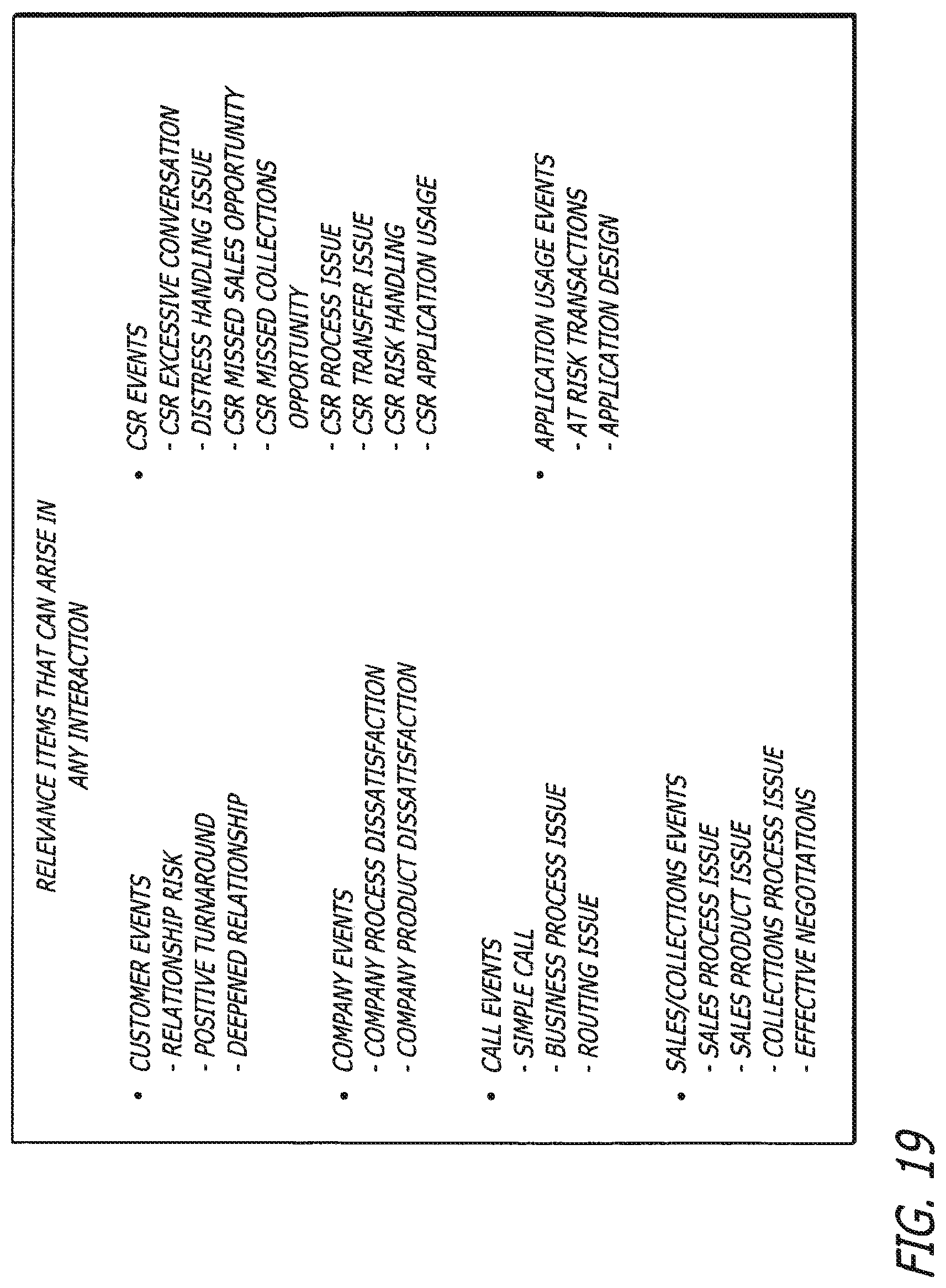
D00017
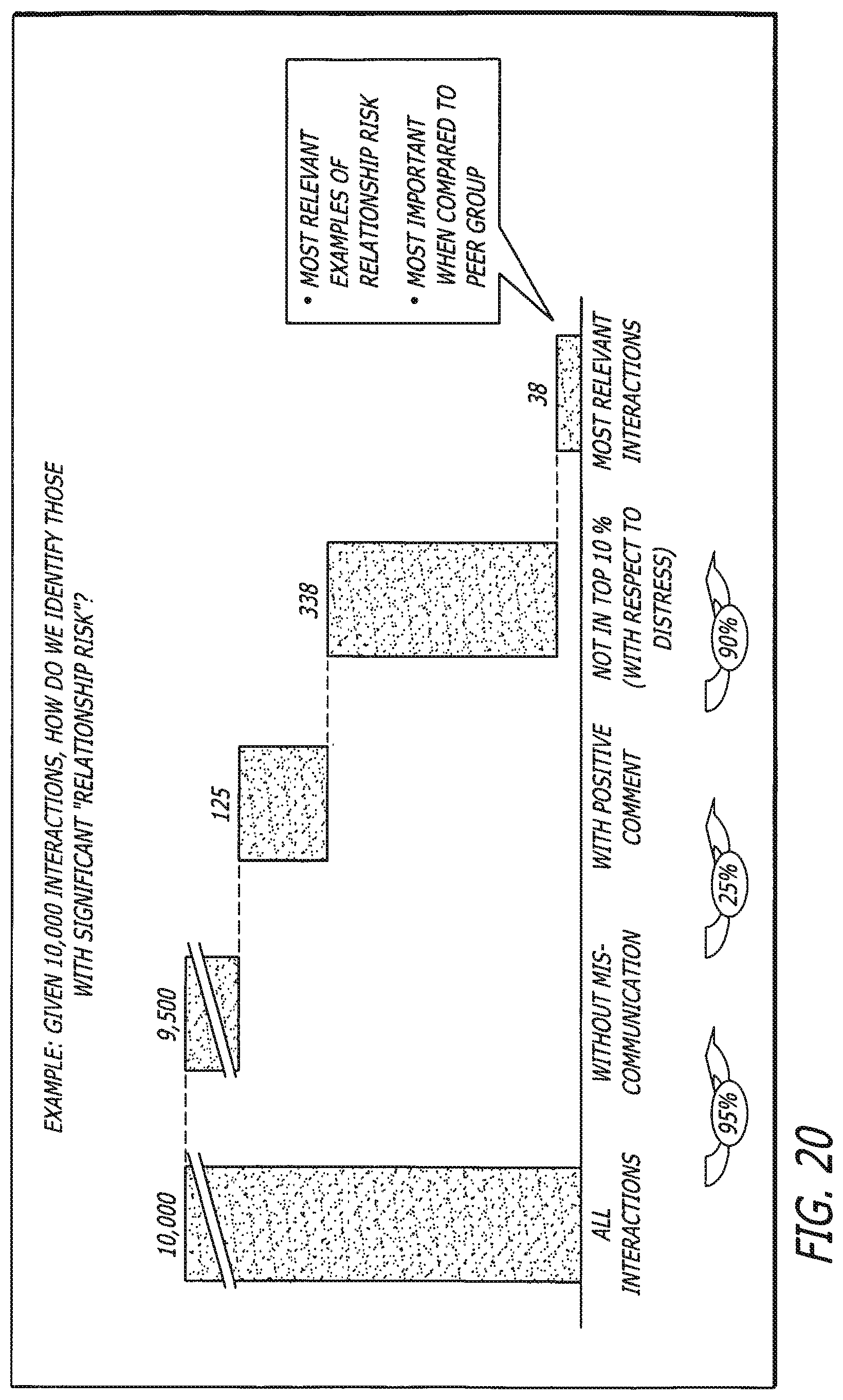
D00018
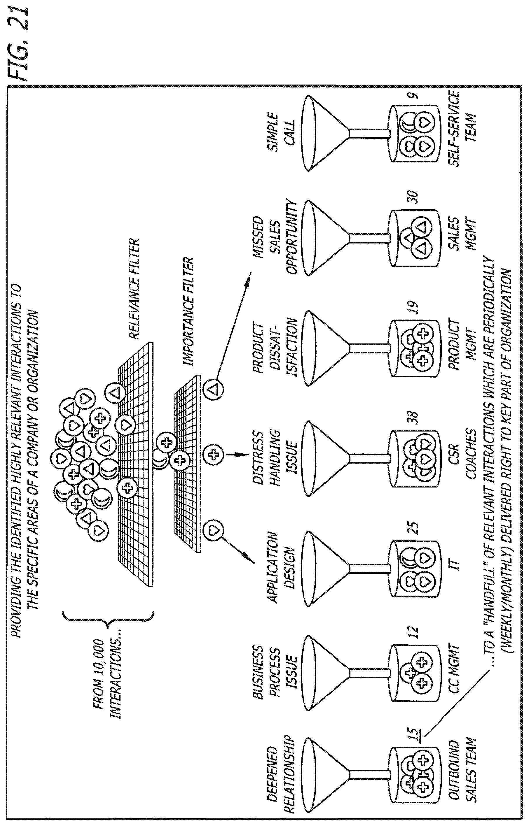
D00019
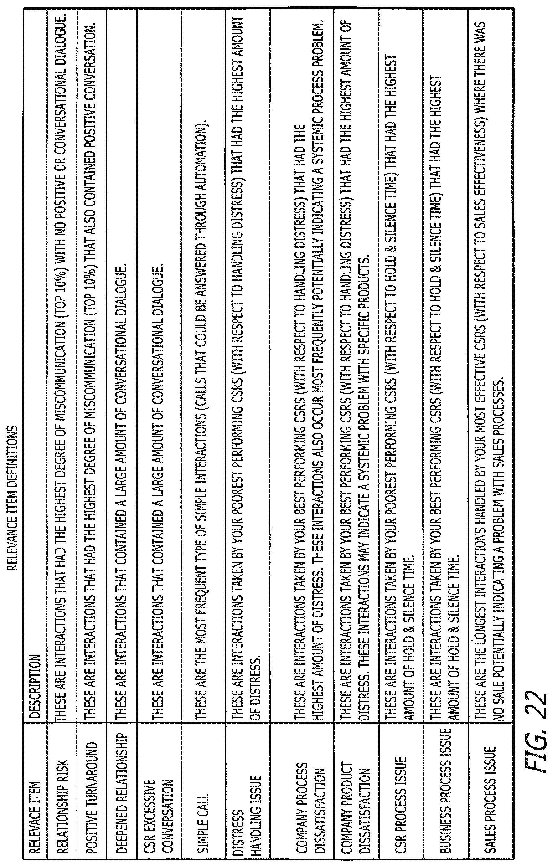
D00020
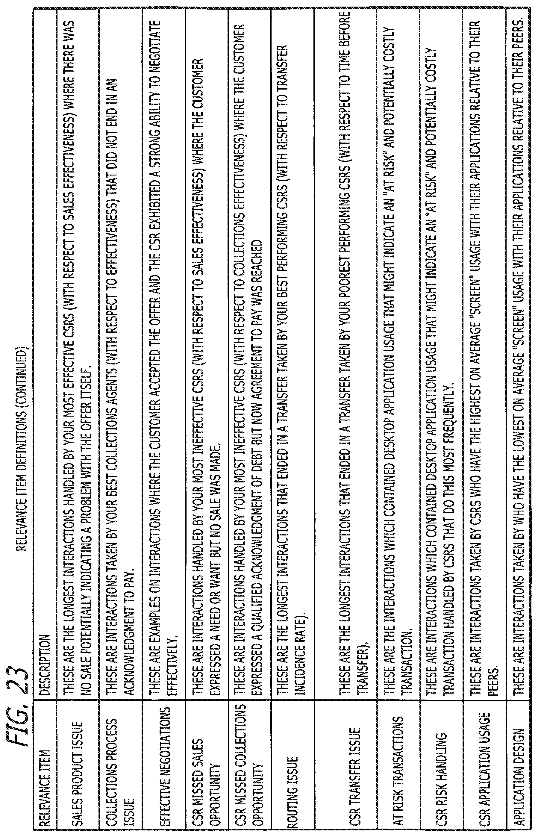
D00021
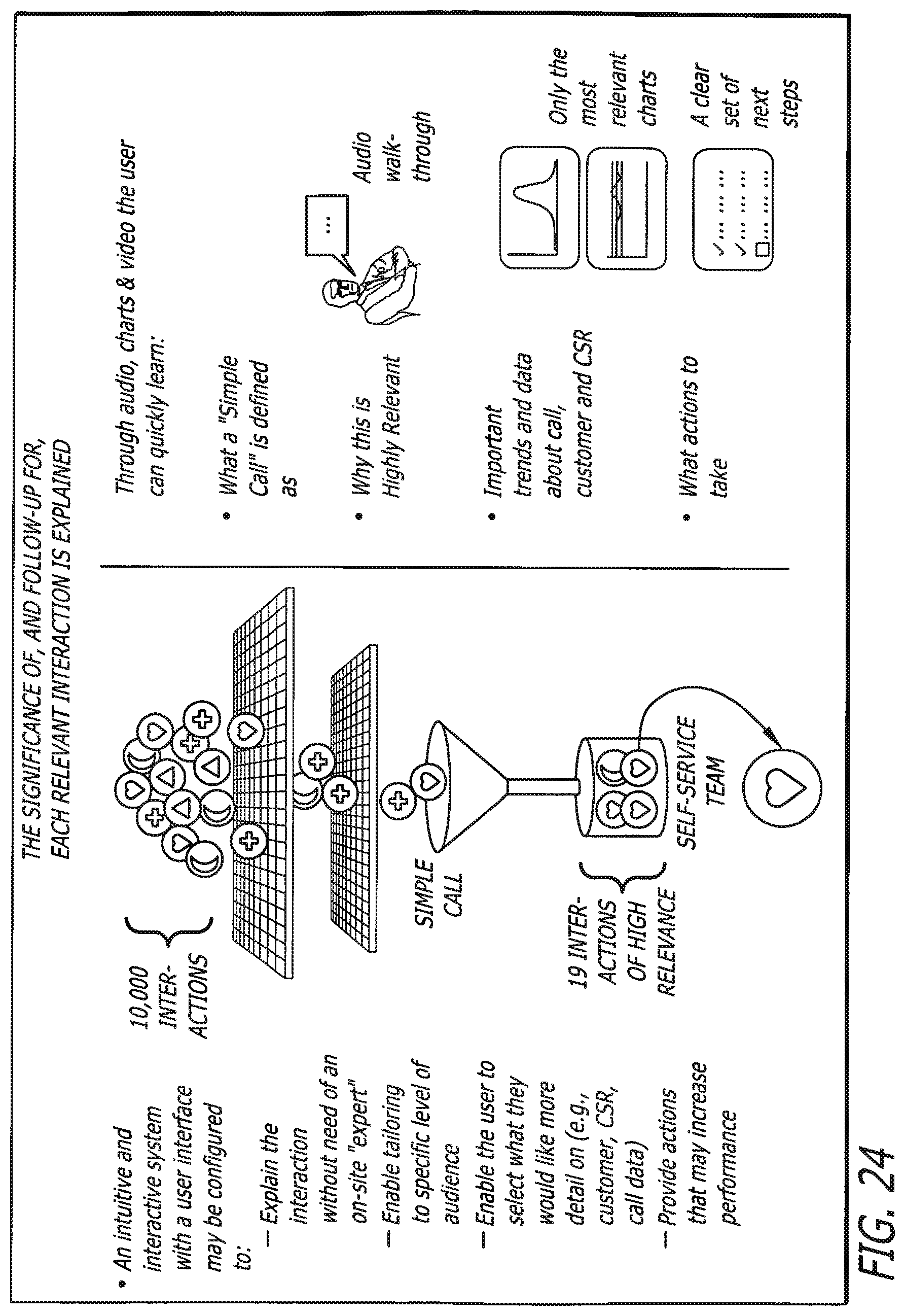
D00022
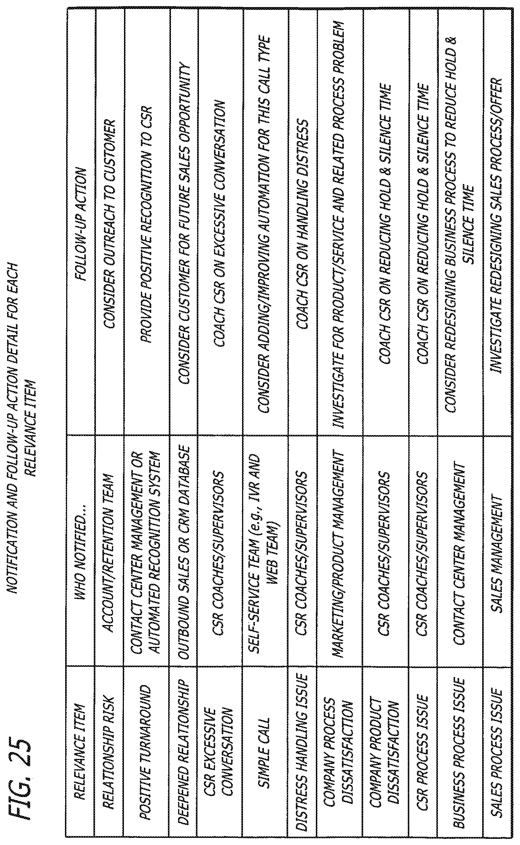
D00023
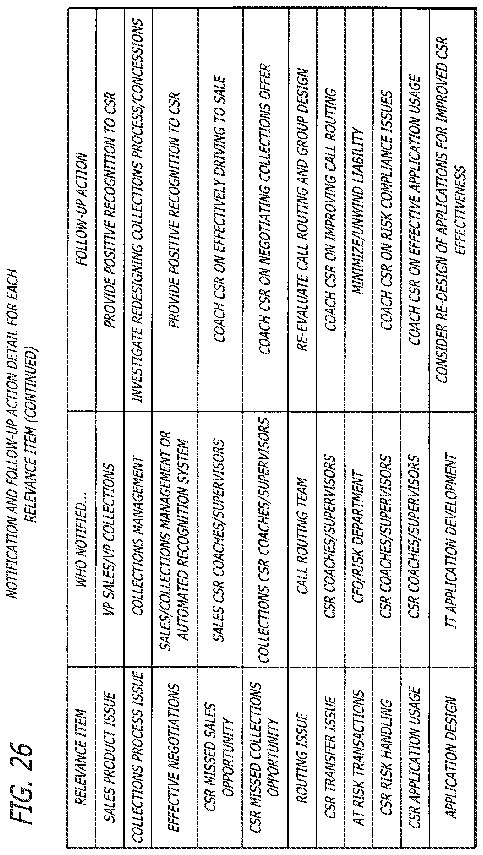
D00024

D00025
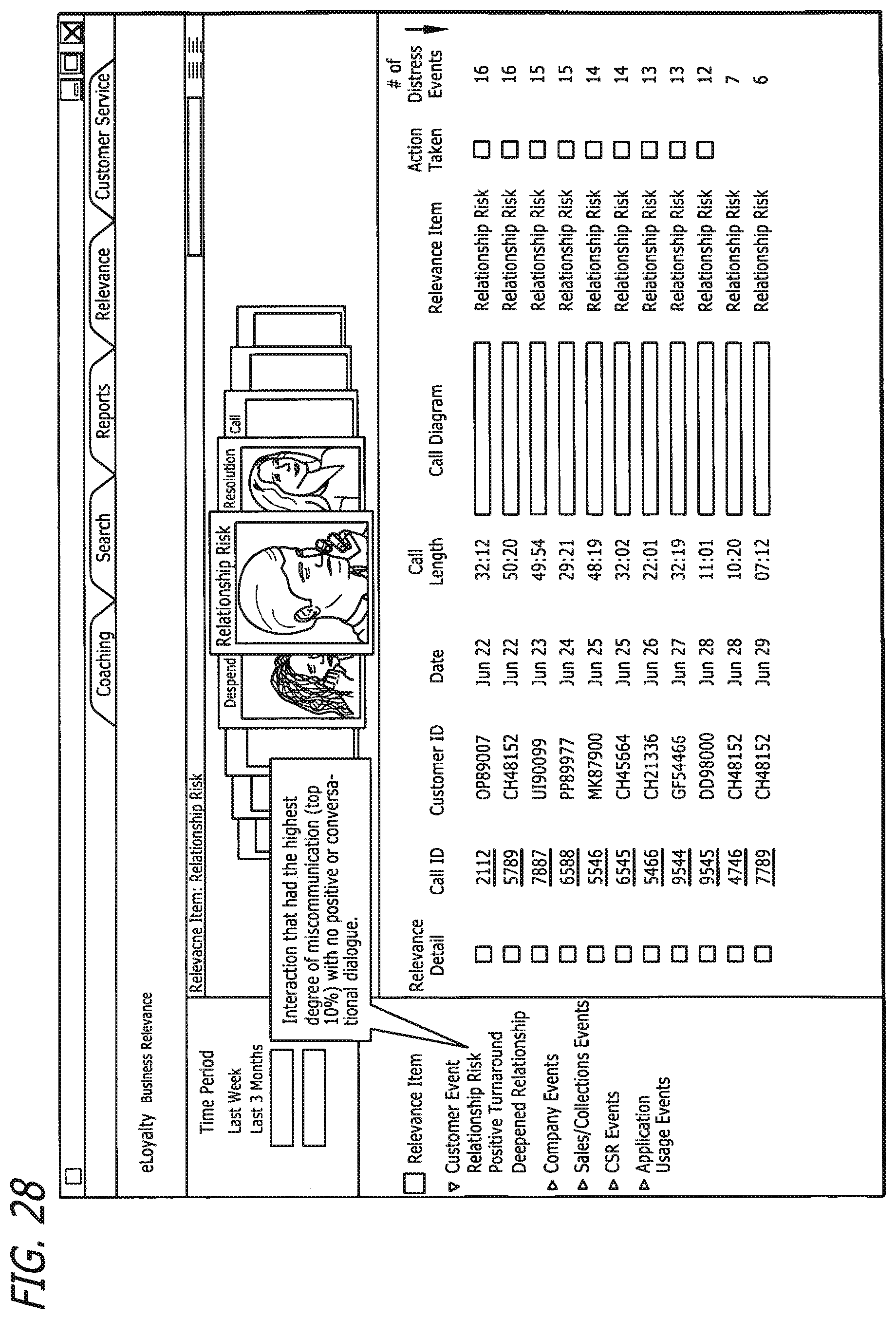
D00026
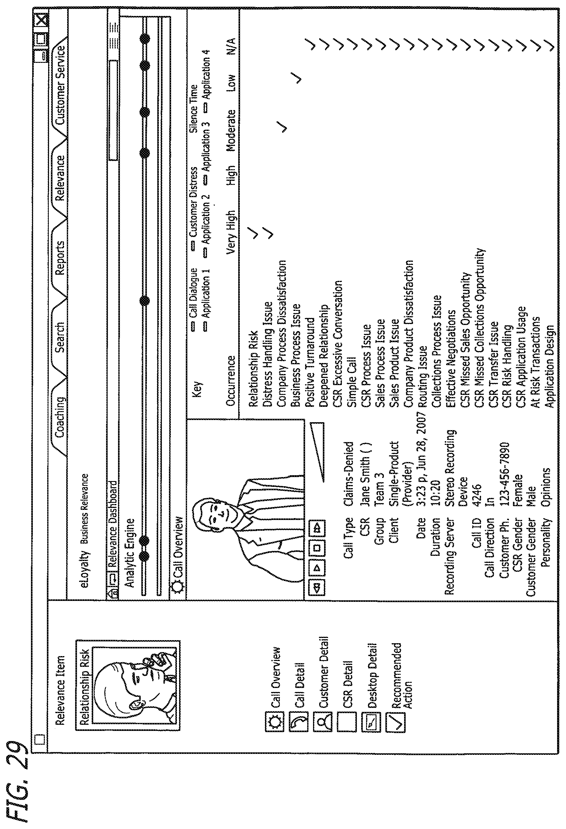
D00027

D00028
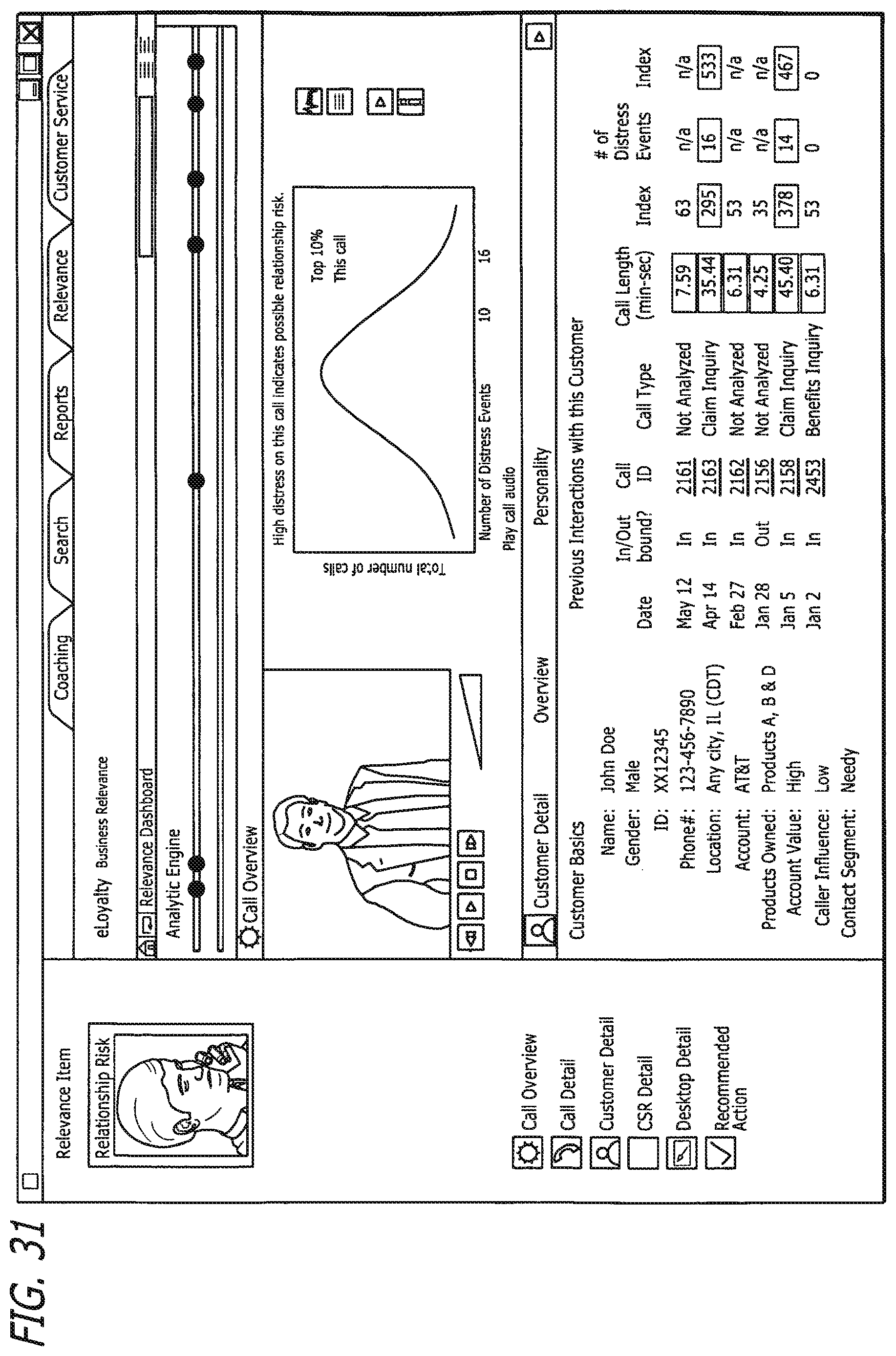
D00029
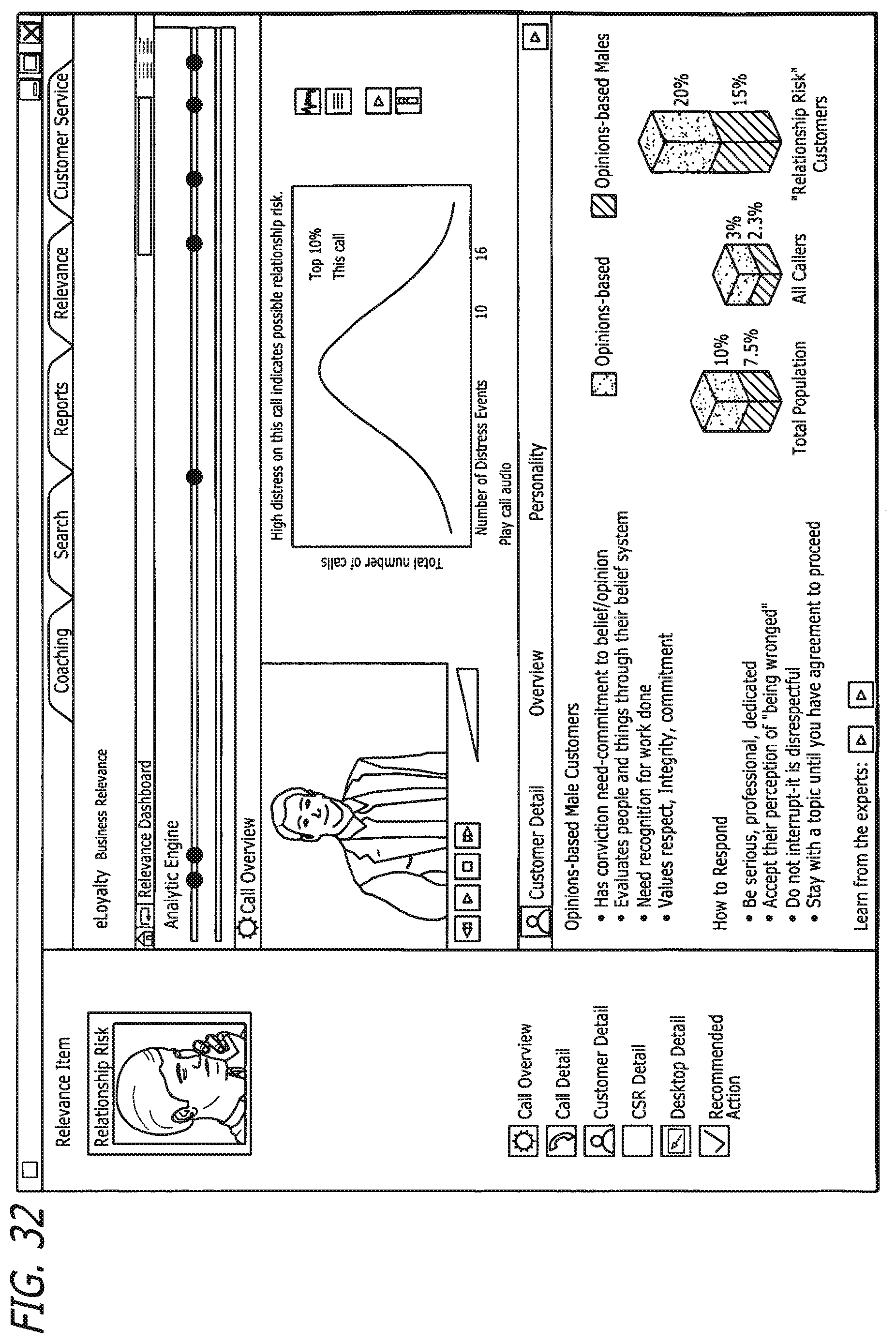
D00030
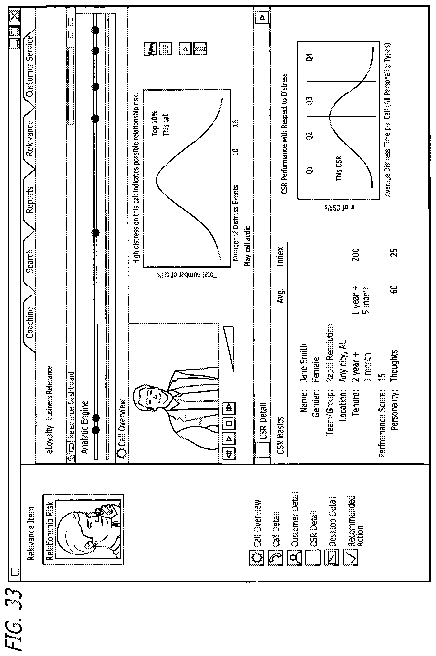
D00031
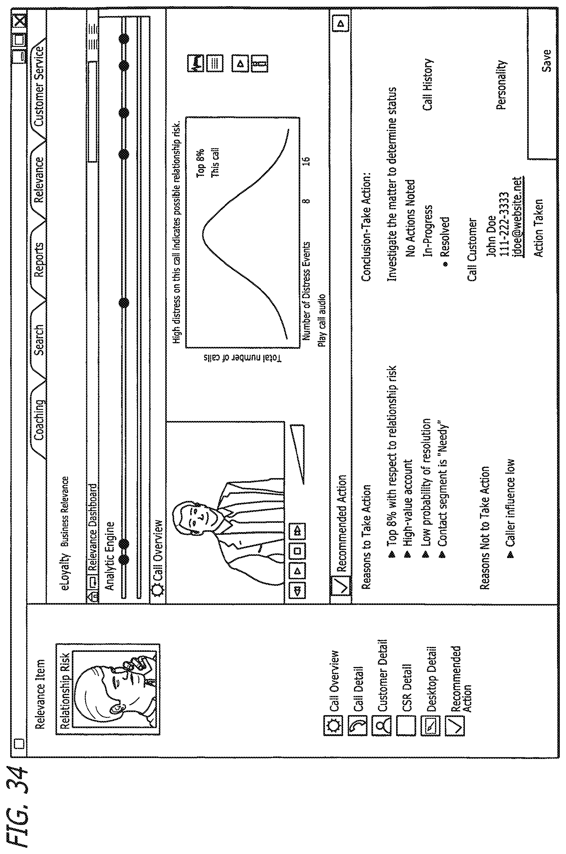
XML
uspto.report is an independent third-party trademark research tool that is not affiliated, endorsed, or sponsored by the United States Patent and Trademark Office (USPTO) or any other governmental organization. The information provided by uspto.report is based on publicly available data at the time of writing and is intended for informational purposes only.
While we strive to provide accurate and up-to-date information, we do not guarantee the accuracy, completeness, reliability, or suitability of the information displayed on this site. The use of this site is at your own risk. Any reliance you place on such information is therefore strictly at your own risk.
All official trademark data, including owner information, should be verified by visiting the official USPTO website at www.uspto.gov. This site is not intended to replace professional legal advice and should not be used as a substitute for consulting with a legal professional who is knowledgeable about trademark law.