Method and apparatus for proximity sensing on a communication device
Bennett , et al. Feb
U.S. patent number 10,567,911 [Application Number 16/150,943] was granted by the patent office on 2020-02-18 for method and apparatus for proximity sensing on a communication device. This patent grant is currently assigned to AT&T Intellectual Property I, L.P.. The grantee listed for this patent is AT&T Intellectual Property I, L.P.. Invention is credited to Donald J. Barnickel, Farhad Barzegar, Robert Bennett, Irwin Gerszberg, Paul Shala Henry, Thomas M. Willis, III.


View All Diagrams
| United States Patent | 10,567,911 |
| Bennett , et al. | February 18, 2020 |
| **Please see images for: ( Certificate of Correction ) ** |
Method and apparatus for proximity sensing on a communication device
Abstract
Aspects of the subject disclosure may include, for example, detecting, by a first receiver of the first group of receivers, a first disturbance in one of a first group of electromagnetic waves and detecting, by a second receiver of a second group of receivers, a second disturbance in one of the second group of electromagnetic waves. A processing system can determine a position of a physical object in proximity to the transmission medium according to locations of the first and second receivers with respect to the transmission medium. Other embodiments are disclosed.
| Inventors: | Bennett; Robert (Southold, NY), Henry; Paul Shala (Holmdel, NJ), Gerszberg; Irwin (Kendall Park, NJ), Barzegar; Farhad (Branchburg, NJ), Willis, III; Thomas M. (Tinton Falls, NJ), Barnickel; Donald J. (Flemington, NJ) | ||||||||||
|---|---|---|---|---|---|---|---|---|---|---|---|
| Applicant: |
|
||||||||||
| Assignee: | AT&T Intellectual Property I,
L.P. (Atlanta, GA) |
||||||||||
| Family ID: | 62488055 | ||||||||||
| Appl. No.: | 16/150,943 | ||||||||||
| Filed: | October 3, 2018 |
Prior Publication Data
| Document Identifier | Publication Date | |
|---|---|---|
| US 20190037356 A1 | Jan 31, 2019 | |
Related U.S. Patent Documents
| Application Number | Filing Date | Patent Number | Issue Date | ||
|---|---|---|---|---|---|
| 15372449 | Dec 8, 2016 | 10136255 | |||
| Current U.S. Class: | 1/1 |
| Current CPC Class: | B64C 39/024 (20130101); H04B 7/0417 (20130101); H04W 16/32 (20130101); H04W 16/18 (20130101); H04W 16/22 (20130101); H04W 4/021 (20130101); H04B 7/0452 (20130101); H04B 7/0608 (20130101); H04B 7/145 (20130101); H04W 16/14 (20130101); H04W 16/28 (20130101); H04W 16/24 (20130101); H04W 4/023 (20130101); H04W 4/025 (20130101); H04B 7/0413 (20130101); H04L 41/22 (20130101) |
| Current International Class: | H04W 16/18 (20090101); H04B 7/0452 (20170101); H04B 7/0413 (20170101); H04B 7/0417 (20170101); H04W 4/021 (20180101); H04W 16/32 (20090101); H04B 7/145 (20060101); H04W 4/02 (20180101); H04B 7/06 (20060101); H04W 16/22 (20090101); H04W 16/14 (20090101); H04W 16/28 (20090101); H04W 16/24 (20090101); B64C 39/02 (20060101); H04L 12/24 (20060101) |
| Field of Search: | ;455/78,101,121,130,135,226.1,269,272,443,562.1 |
References Cited [Referenced By]
U.S. Patent Documents
| 2685068 | July 1954 | Goubau |
| 2852753 | September 1958 | Walter et al. |
| 2867776 | January 1959 | Wilkinson |
| 2912695 | November 1959 | Cutler |
| 2921277 | January 1960 | Goubau |
| 3201724 | August 1965 | Hafner |
| 3566317 | February 1971 | Theodore |
| 4783665 | November 1988 | Lier et al. |
| 4825221 | April 1989 | Suzuki et al. |
| 5381160 | January 1995 | Landmeier |
| 5402151 | March 1995 | Duwaer |
| 5750941 | May 1998 | Ishikawa et al. |
| 5889449 | March 1999 | Fiedziuszko |
| 5937335 | August 1999 | Park et al. |
| 6239377 | May 2001 | Nishikawa et al. |
| 6285325 | September 2001 | Nalbandian et al. |
| 6948371 | September 2005 | Tanaka et al. |
| 7009471 | March 2006 | Elmore |
| 7043271 | May 2006 | Seto et al. |
| 7280033 | October 2007 | Berkman et al. |
| 7301424 | November 2007 | Suarez-Gartner et al. |
| 7345623 | March 2008 | McEwan et al. |
| 7567154 | July 2009 | Elmore |
| 7590404 | September 2009 | Johnson et al. |
| 7593067 | September 2009 | Taguchi et al. |
| 7796122 | September 2010 | Shih et al. |
| 7915980 | March 2011 | Hardacker et al. |
| 7925235 | April 2011 | Konya et al. |
| 8064744 | November 2011 | Atkins et al. |
| 8159385 | April 2012 | Farneth et al. |
| 8212635 | July 2012 | Miller, II et al. |
| 8229368 | July 2012 | Immendorf |
| 8237617 | August 2012 | Johnson et al. |
| 8253516 | August 2012 | Miller, II et al. |
| 8269583 | September 2012 | Miller, II et al. |
| 8344829 | January 2013 | Miller, II et al. |
| 8599150 | December 2013 | Philipp |
| 8736502 | May 2014 | Mehr et al. |
| 8754852 | June 2014 | Lee et al. |
| 8897697 | November 2014 | Bennett et al. |
| 8929841 | January 2015 | Rofougaran et al. |
| 9113347 | August 2015 | Paul Shala |
| 9158418 | October 2015 | Oda et al. |
| 9201556 | December 2015 | Free et al. |
| 9209902 | December 2015 | Willis, III et al. |
| 9312919 | April 2016 | Barzegar et al. |
| 9417731 | August 2016 | Premont et al. |
| 9459746 | October 2016 | Zarraga et al. |
| 9461706 | October 2016 | Bennett et al. |
| 9490869 | November 2016 | Henry |
| 9495037 | November 2016 | King-Smith |
| 9509415 | November 2016 | Henry et al. |
| 9520945 | December 2016 | Gerszberg et al. |
| 9525524 | December 2016 | Barzegar et al. |
| 9544006 | January 2017 | Henry et al. |
| 9564947 | February 2017 | Stuckman et al. |
| 9577306 | February 2017 | Willis, III et al. |
| 9608692 | March 2017 | Willis, III et al. |
| 9608740 | March 2017 | Henry et al. |
| 9615269 | April 2017 | Henry et al. |
| 9627768 | April 2017 | Henry et al. |
| 9628116 | April 2017 | Willis, III et al. |
| 9640850 | May 2017 | Henry et al. |
| 9653770 | May 2017 | Henry et al. |
| 9680670 | June 2017 | Henry et al. |
| 9692101 | June 2017 | Henry et al. |
| 9705561 | July 2017 | Henry et al. |
| 9705571 | July 2017 | Gerszberg et al. |
| 9742462 | August 2017 | Bennett et al. |
| 9748626 | August 2017 | Henry et al. |
| 9749053 | August 2017 | Henry et al. |
| 9722318 | September 2017 | Adriazola et al. |
| 9768833 | September 2017 | Fuchs et al. |
| 9769020 | September 2017 | Henry et al. |
| 9780834 | October 2017 | Henry et al. |
| 9793951 | October 2017 | Henry et al. |
| 9793954 | October 2017 | Bennett et al. |
| 9847566 | December 2017 | Henry et al. |
| 9853342 | December 2017 | Henry et al. |
| 9860075 | January 2018 | Gerszberg et al. |
| 9865911 | January 2018 | Henry et al. |
| 9866309 | January 2018 | Bennett et al. |
| 9871282 | January 2018 | Henry et al. |
| 9871283 | January 2018 | Henry et al. |
| 9876264 | January 2018 | Barnickel et al. |
| 9876570 | January 2018 | Henry et al. |
| 9876605 | January 2018 | Henry et al. |
| 9882257 | January 2018 | Henry et al. |
| 9893795 | February 2018 | Willis et al. |
| 9912381 | March 2018 | Bennett et al. |
| 9917341 | March 2018 | Henry et al. |
| 9991580 | June 2018 | Henry et al. |
| 9997819 | June 2018 | Bennett et al. |
| 9998172 | June 2018 | Barzegar et al. |
| 9998870 | June 2018 | Bennett et al. |
| 9999038 | June 2018 | Barzegar et al. |
| 10003364 | June 2018 | Willis, III et al. |
| 10009063 | June 2018 | Gerszberg et al. |
| 10009065 | June 2018 | Henry et al. |
| 10009067 | June 2018 | Birk et al. |
| 10009901 | June 2018 | Gerszberg |
| 10027397 | July 2018 | Kim |
| 10027427 | July 2018 | Vannucci et al. |
| 10033107 | July 2018 | Henry et al. |
| 10033108 | July 2018 | Henry et al. |
| 10044409 | August 2018 | Barzegar et al. |
| 10051483 | August 2018 | Barzegar et al. |
| 10051488 | August 2018 | Vannucci et al. |
| 10062970 | August 2018 | Vannucci et al. |
| 10069535 | September 2018 | Vannucci et al. |
| 10079661 | September 2018 | Gerszberg et al. |
| 10090606 | October 2018 | Henry et al. |
| 10096883 | October 2018 | Henry et al. |
| 10103777 | October 2018 | Henry et al. |
| 10103801 | October 2018 | Bennett et al. |
| 10123217 | November 2018 | Barzegar et al. |
| 10129057 | November 2018 | Willis, III et al. |
| 10135145 | November 2018 | Henry et al. |
| 10136434 | November 2018 | Gerszberg et al. |
| 10142086 | November 2018 | Bennett et al. |
| 10148016 | December 2018 | Johnson et al. |
| 10154493 | December 2018 | Bennett et al. |
| 10170840 | January 2019 | Henry et al. |
| 10171158 | January 2019 | Barzegar et al. |
| 10200106 | February 2019 | Barzegar et al. |
| 10205212 | February 2019 | Henry et al. |
| 10205231 | February 2019 | Henry et al. |
| 10205655 | February 2019 | Barzegar et al. |
| 10224981 | March 2019 | Henry et al. |
| 10230426 | March 2019 | Henry et al. |
| 10230428 | March 2019 | Barzegar et al. |
| 10243270 | March 2019 | Henry et al. |
| 10244408 | March 2019 | Vannucci et al. |
| 10264586 | April 2019 | Beattie, Jr. et al. |
| 10276907 | April 2019 | Bennett et al. |
| 10284261 | May 2019 | Barzegar et al. |
| 10291286 | May 2019 | Henry et al. |
| 10305190 | May 2019 | Britz et al. |
| 10305192 | May 2019 | Rappaport |
| 10305197 | May 2019 | Henry et al. |
| 10312567 | June 2019 | Bennett et al. |
| 10320586 | June 2019 | Henry et al. |
| 10326495 | June 2019 | Barzegar et al. |
| 10340573 | July 2019 | Johnson et al. |
| 10340600 | July 2019 | Henry et al. |
| 10340979 | July 2019 | Barzegar et al. |
| 10348391 | July 2019 | Bennett et al. |
| 10355745 | July 2019 | Henry et al. |
| 10361489 | July 2019 | Britz et al. |
| 10371889 | August 2019 | Barzegar et al. |
| 10374277 | August 2019 | Henry et al. |
| 10374278 | August 2019 | Henry et al. |
| 10374281 | August 2019 | Henry et al. |
| 10374316 | August 2019 | Bennett et al. |
| 10389029 | August 2019 | Henry et al. |
| 10389037 | August 2019 | Johnson et al. |
| 10389403 | August 2019 | Henry et al. |
| 10389419 | August 2019 | Johnson et al. |
| 2004/0113756 | June 2004 | Mollenkopf et al. |
| 2004/0169572 | September 2004 | Elmore et al. |
| 2004/0218688 | November 2004 | Santhoff et al. |
| 2005/0017825 | January 2005 | Hansen |
| 2005/0042989 | February 2005 | Ho et al. |
| 2005/0111533 | May 2005 | Berkman et al. |
| 2005/0237168 | October 2005 | Matsukawa et al. |
| 2005/0258920 | November 2005 | Elmore et al. |
| 2006/0083269 | April 2006 | Kang et al. |
| 2008/0064331 | March 2008 | Washiro et al. |
| 2008/0125036 | May 2008 | Konya et al. |
| 2008/0211727 | September 2008 | Elmore et al. |
| 2008/0252541 | October 2008 | Diaz et al. |
| 2009/0079660 | March 2009 | Elmore et al. |
| 2009/0258652 | October 2009 | Lambert et al. |
| 2010/0026490 | February 2010 | Butler |
| 2010/0225426 | September 2010 | Unger et al. |
| 2010/0277003 | November 2010 | Von et al. |
| 2011/0110404 | May 2011 | Washiro |
| 2011/0132658 | June 2011 | Miller, II et al. |
| 2011/0136432 | June 2011 | Miller, II et al. |
| 2011/0140911 | June 2011 | Pant et al. |
| 2011/0187578 | August 2011 | Farneth et al. |
| 2012/0133373 | May 2012 | Ali |
| 2012/0306587 | December 2012 | Strid et al. |
| 2012/0313895 | December 2012 | Haroun et al. |
| 2013/0064311 | March 2013 | Turner et al. |
| 2013/0169499 | July 2013 | Lin et al. |
| 2013/0219308 | August 2013 | Britton et al. |
| 2013/0234961 | September 2013 | Garfinkel et al. |
| 2014/0167882 | June 2014 | Shinoda et al. |
| 2014/0285277 | September 2014 | Herbsommer et al. |
| 2015/0188584 | July 2015 | Laurent-Michel |
| 2016/0026301 | January 2016 | Zhou et al. |
| 2016/0080839 | March 2016 | Fuchs et al. |
| 2016/0094318 | March 2016 | Shattil |
| 2016/0094879 | March 2016 | Gerszberg et al. |
| 2016/0112093 | April 2016 | Barzegar |
| 2016/0139731 | May 2016 | Kim |
| 2016/0164571 | June 2016 | Bennett et al. |
| 2016/0182096 | June 2016 | Panioukov et al. |
| 2016/0188291 | June 2016 | Vilermo et al. |
| 2016/0315662 | October 2016 | Henry |
| 2016/0359541 | December 2016 | Bennett |
| 2016/0359546 | December 2016 | Bennett |
| 2016/0359547 | December 2016 | Bennett et al. |
| 2016/0360533 | December 2016 | Bennett et al. |
| 2016/0365966 | December 2016 | Bennett et al. |
| 2017/0012667 | January 2017 | Bennett |
| 2017/0018856 | January 2017 | Henry et al. |
| 2017/0033465 | February 2017 | Henry et al. |
| 2017/0033953 | February 2017 | Henry et al. |
| 2017/0033954 | February 2017 | Henry et al. |
| 2017/0079037 | March 2017 | Gerszberg et al. |
| 2017/0079038 | March 2017 | Gerszberg et al. |
| 2017/0079039 | March 2017 | Gerszberg et al. |
| 2017/0085003 | March 2017 | Johnson et al. |
| 2017/0093693 | March 2017 | Barzegar et al. |
| 2017/0110795 | April 2017 | Henry |
| 2017/0110804 | April 2017 | Henry et al. |
| 2017/0229782 | August 2017 | Adriazola et al. |
| 2018/0048497 | February 2018 | Henry et al. |
| 2018/0054232 | February 2018 | Henry et al. |
| 2018/0054233 | February 2018 | Henry et al. |
| 2018/0054234 | February 2018 | Stuckman et al. |
| 2018/0062886 | March 2018 | Paul et al. |
| 2018/0069594 | March 2018 | Henry et al. |
| 2018/0069731 | March 2018 | Henry et al. |
| 2018/0074568 | March 2018 | Priyadarshi et al. |
| 2018/0076982 | March 2018 | Henry et al. |
| 2018/0076988 | March 2018 | Willis, III et al. |
| 2018/0077709 | March 2018 | Gerszberg |
| 2018/0108997 | April 2018 | Henry et al. |
| 2018/0108998 | April 2018 | Henry et al. |
| 2018/0108999 | April 2018 | Henry et al. |
| 2018/0115040 | April 2018 | Bennett et al. |
| 2018/0115058 | April 2018 | Henry et al. |
| 2018/0115060 | April 2018 | Bennett et al. |
| 2018/0115075 | April 2018 | Bennett et al. |
| 2018/0115081 | April 2018 | Johnson et al. |
| 2018/0123207 | May 2018 | Henry et al. |
| 2018/0123208 | May 2018 | Henry et al. |
| 2018/0123643 | May 2018 | Henry et al. |
| 2018/0123836 | May 2018 | Henry et al. |
| 2018/0151957 | May 2018 | Bennett et al. |
| 2018/0159195 | June 2018 | Henry et al. |
| 2018/0159196 | June 2018 | Henry et al. |
| 2018/0159197 | June 2018 | Henry et al. |
| 2018/0159228 | June 2018 | Britz et al. |
| 2018/0159229 | June 2018 | Britz |
| 2018/0159230 | June 2018 | Henry et al. |
| 2018/0159232 | June 2018 | Henry et al. |
| 2018/0159235 | June 2018 | Wolniansky |
| 2018/0159238 | June 2018 | Wolniansky |
| 2018/0159240 | June 2018 | Henry et al. |
| 2018/0159243 | June 2018 | Britz et al. |
| 2018/0166761 | June 2018 | Henry et al. |
| 2018/0166784 | June 2018 | Johnson et al. |
| 2018/0166785 | June 2018 | Henry et al. |
| 2018/0166787 | June 2018 | Johnson et al. |
| 2018/0167130 | June 2018 | Vannucci |
| 2018/0167772 | June 2018 | Bennett et al. |
| 2018/0167927 | June 2018 | Beattie, Jr. et al. |
| 2018/0302162 | October 2018 | Gerszberg et al. |
| 2019/0013577 | January 2019 | Henry et al. |
| 2019/0013837 | January 2019 | Henry et al. |
| 2019/0074563 | March 2019 | Henry et al. |
| 2019/0074580 | March 2019 | Henry et al. |
| 2019/0074864 | March 2019 | Henry et al. |
| 2019/0074865 | March 2019 | Henry et al. |
| 2019/0074878 | March 2019 | Henry et al. |
| 2019/0081747 | March 2019 | Barzegar et al. |
| 2019/0104012 | April 2019 | Barzegar et al. |
| 2019/0104419 | April 2019 | Barzegar et al. |
| 2019/0104420 | April 2019 | Barzegar et al. |
| 2019/0115642 | April 2019 | Henry et al. |
| 2019/0123442 | April 2019 | Vannucci et al. |
| 2019/0123783 | April 2019 | Henry et al. |
| 2019/0131717 | May 2019 | Vannucci |
| 2019/0131718 | May 2019 | Vannucci |
| 2019/0140679 | May 2019 | Vannucci et al. |
| 2019/0141714 | May 2019 | Willis, III et al. |
| 2019/0150072 | May 2019 | Barzegar |
| 2019/0173190 | June 2019 | Johnson et al. |
| 2019/0173601 | June 2019 | Wolniansky et al. |
| 2019/0174506 | June 2019 | Willis, III et al. |
| 2019/0181532 | June 2019 | Vannucci et al. |
| 2019/0181683 | June 2019 | Vannucci et al. |
| 2515560 | Feb 2007 | CA | |||
| 201207179 | Mar 2009 | CN | |||
| 2568528 | Dec 2017 | EP | |||
| 8605327 | Sep 1986 | WO | |||
| 2012050069 | Apr 2012 | WO | |||
| 2013008292 | Jan 2013 | WO | |||
| 2014112994 | Jul 2014 | WO | |||
| 2016086306 | Jun 2016 | WO | |||
| 2018106455 | Jun 2018 | WO | |||
| 2018106684 | Jun 2018 | WO | |||
| 2018106915 | Jun 2018 | WO | |||
| 2019050752 | Mar 2019 | WO | |||
Other References
|
Villaran, Michael et al., "Condition Monitoring of Cables Task 3 Report: Condition Monitoring Techniques for Electric Cables", Brookhaven National Laboratory, Technical Report, Nov. 30, 2009, 89 pages. cited by applicant . "International Search Report and Written Opinion", PCT/US2018/015634, dated Jun. 25, 2018, 8 pages. cited by applicant . "Technology Brief 13: Touchscreens and Active Digitizers", https://web.archive.org/web/20100701004625/http://web.engr.oregonstate.ed- u/.about.moon/engr203/read/read4.pdf, 2010, 289-311. cited by applicant . Akalin, Tahsin et al., "Single-Wire Transmission Lines at Terahertz Frequencies", IEEE Transactions on Microwave Theory and Techniques, vol. 54, No. 6, 2006, 2762-2767. cited by applicant . Alam, M. N. et al., "Novel Surface Wave Exciters for Power Line Fault Detection and Communications", Department of Electrical Engineering, University of South Carolina, Antennas and Propagation (APSURSI), 2011 IEEE International Symposium, IEEE, 2011, 1-4. cited by applicant . Baanto, "Surface Acoustive Wave (SAW) Touch Screen", http://baanto.com/surface-acoustic-wave-saw-touch-screen, 2016, 4 pages. cited by applicant . Barlow, H. M. et al., "Surface Waves", 621.396.11 : 538.566, Paper No. 1482 Radio Section, 1953, pp. 329-341. cited by applicant . Corridor Systems, "A New Approach to Outdoor DAS Network Physical Layer Using E-Line Technology", Mar. 2011, 5 pages. cited by applicant . Elmore, Glenn et al., "A Surface Wave Transmission Line", QEX, May/Jun. 2012, pp. 3-9. cited by applicant . Elmore, Glenn, "Introduction to the Propagating Wave on a Single Conductor", www.corridor.biz, Jul. 27, 2009, 30 pages. cited by applicant . Friedman, M et al., "Low-Loss RF Transport Over Long Distances", IEEE Transactions on Microwave Theory and Techniques, vol. 49, No. 2, Feb. 2001, 8 pages. cited by applicant . Goubau, Georg et al., "Investigation of a Surface-Wave Line for Long Distance Transmission", 1952, 263-267. cited by applicant . Goubau, Georg et al., "Investigations with a Model Surface Wave Transmission Line", IRE Transactions on Antennas and Propagation, 1957, 222-227. cited by applicant . Goubau, Georg , "Open Wire Lines", IRE Transactions on Microwave Theory and Techniques, 1956, 197-200. cited by applicant . Goubau, Georg, "Single-Conductor Surface-Wave Transmission Lines", Proceedings of the I.R.E., 1951, 619-624. cited by applicant . Goubau, Georg, "Surface Waves and Their Application to Transmission Lines", Radio Communication Branch, Coles Signal Laboratory, Mar. 10, 1950, 1119-1128. cited by applicant . Goubau, Georg, "Waves on Interfaces", IRE Transactions on Antennas and Propagation, Dec. 1959, 140-146. cited by applicant . Rekimoto, Jun , "SmartSkin: An Infrastructure for Freehand Manipulation on Interactive Surfaces", https://vs.inf.ethz.ch/edu/SS2005/DS/papers/surfaces/rekimoto-smartskin.p- df, 2002, 8 pages. cited by applicant . Ren-Bin, Zhong et al., "Surface plasmon wave propagation along single metal wire", Chin. Phys. B, vol. 21, No. 11, May 2, 2012, 9 pages. cited by applicant . Schoning, Johannes et al., "Multi-Touch Surfaces: A Technical Guide", Johannes Schoning, Institute for Geoinformatics University of Munster, Technical Report TUM-I0833, 2008, 19 pages. cited by applicant . Sommerfeld, A., "On the propagation of electrodynamic waves along a wire", Annals of Physics And Chemistry New Edition, vol. 67, No. 2, 1899, 72 pages. cited by applicant . Wang, Hao et al., "Dielectric Loaded Substrate Integrated Waveguide (SIW)--Plan Horn Antennas", IEEE Transactions on Antennas and Propagation, IEEE Service Center, Piscataway, NJ, US, vol. 56, No. 3, Mar. 1, 2010, 640-647. cited by applicant . Wang, Kanglin, "Dispersion of Surface Plasmon Polaritons on Metal Wires in the Terahertz Frequency Range", Physical Review Letters, PRL 96, 157401, 2006, 4 pages. cited by applicant. |
Primary Examiner: Casca; Fred A
Attorney, Agent or Firm: Guntin & Gust, PLC Gingher; Robert
Parent Case Text
CROSS REFERENCE TO RELATED APPLICATIONS
This application is a continuation of U.S. patent application Ser. No. 15/372,449 filed Dec. 8, 2016. The contents of each of the foregoing are hereby incorporated by reference into this application as if set forth herein in full.
Claims
What is claimed is:
1. A device, comprising: a first group of transmitters and a second group of transmitters coupled with a transmission medium, wherein the transmission medium comprises an outer surface; a first group of receivers and a second group of receivers coupled with the transmission medium; and a processing system including a processor, wherein each of the first group of transmitters generates a first electromagnetic wave resulting in a first group of electromagnetic waves that is guided by the transmission medium to a corresponding one of the first group of receivers, wherein each of the second group of transmitters generates a second electromagnetic wave resulting in a second group of electromagnetic waves that is guided by the transmission medium to a corresponding one of the second group of receivers, wherein a first disturbance is detected by the processing system in a first particular electromagnetic wave of the first group of electromagnetic waves that is transmitted to a first receiver of the first group of receivers, wherein a second disturbance is detected by the processing system in a second particular electromagnetic wave of the second group of electromagnetic waves that is transmitted to a second receiver of the second group of receivers, and wherein the processing system determines a position of a physical object in proximity to the transmission medium according to the detection of the first and second disturbances and according to a determination that the first and second particular electromagnetic waves were transmitted to the first and second receivers, respectively.
2. The device of claim 1, wherein the first and second groups of electromagnetic waves comprise Zenneck waves.
3. The device of claim 1, wherein the first group of electromagnetic waves propagates along the transmission medium orthogonally to the second group of electromagnetic waves.
4. The device of claim 1, wherein at least one of the first group of electromagnetic waves has one or more frequencies that are different from at least one of the second group of electromagnetic waves.
5. The device of claim 1, wherein the first group of electromagnetic waves has a first mode that is different from a second mode of the second group of electromagnetic waves.
6. The device of claim 1, wherein a number of the first group of transmitters is equal to a number of the first group of receivers, and wherein a number of the second group of transmitters is equal to a number of the second group of receivers.
7. The device of claim 1, wherein at least one electromagnetic wave of the first group of electromagnetic waves differs from another electromagnetic wave of the first group of electromagnetic waves.
8. The device of claim 7, further comprising a display screen, wherein the display screen comprises the transmission medium, wherein the processing system presents a graphical symbol on the display screen corresponding to the position of the physical object in proximity to the transmission medium.
9. The device of claim 1, further comprising a transceiver, wherein the processing system provides communication services utilizing the transceiver.
10. The device of claim 1, wherein the detection of the first disturbance is based on the first particular electromagnetic wave not being received by the first receiver, and wherein the detection of the second disturbance is based on the second particular electromagnetic wave not being received by the second receiver.
11. The device of claim 1, wherein the detection of the first disturbance is based on determining a first parameter change for the first particular electromagnetic wave, and wherein the detection of the second disturbance is based on determining a second parameter change for the second particular electromagnetic wave.
12. The device of claim 1, wherein the first and second electromagnetic waves propagate along the transmission medium without requiring an electrical return path.
13. A method comprising: generating, by a first transmitter of a communication device, a first electromagnetic wave that propagates along and is guided by a physical transmission medium of the communication device; generating, by a second transmitter of the communication device, a second electromagnetic wave that propagates along the transmission medium; detecting, by a processing system of the communication device, a first disturbance in the first electromagnetic wave; detecting, by the processing system, a second disturbance in the second electromagnetic wave; and determining, by the processing system, a position of a physical object in proximity to the physical transmission medium according to the detecting of the first and second disturbances and according to a determination that the first and second electromagnetic waves were transmitted to a first receiver and a second receiver of the communication device, respectively.
14. The method of claim 13, wherein a first group of transmitters including the first transmitter and a first group of receivers including the first receiver are positioned on opposing ends of the transmission medium, and wherein a second group of transmitters including the second transmitter and a second group of receivers including the second receiver are positioned on other opposing ends of the transmission medium.
15. The method of claim 13, wherein the first and second electromagnetic waves comprise Zenneck waves.
16. The method of claim 13, wherein the first electromagnetic wave has one of a first frequency, a first mode or a combination thereof that is different from one of a second frequency, a second mode or a combination thereof of the second electromagnetic wave.
17. The method of claim 13, further comprising presenting, by the processing system, a graphical symbol on a display screen of the communication device, wherein the graphical symbol is presented at a display location corresponding to the position of the physical object in proximity to the transmission medium.
18. The method of claim 13, wherein the detecting of the first disturbance is based on determining a first parameter change for the first electromagnetic wave, and wherein the detecting of the second disturbance is based on determining a second parameter change for the second electromagnetic wave.
19. A non-transitory machine-readable storage device, comprising instructions, wherein responsive to executing the instructions, a processing system of a communication device performs operations, the operations comprising: detecting a first disturbance in a first electromagnetic wave of a first group of electromagnetic waves that propagates along and is guided by a physical transmission medium of the communication device; detecting a second disturbance in a second electromagnetic wave of a second group of electromagnetic waves that propagates along the transmission medium; identifying a first receiver that received or was intended to receive the first electromagnetic wave, the first receiver being identified from among a group of first receivers of the communication device; identifying a second receiver that received or was intended to receive the second electromagnetic wave, the second receiver being identified from among a group of second receivers of the communication device; and determining a position of a physical object in proximity to the transmission medium according to the identifying of the first and second receivers.
20. The non-transitory machine-readable storage device of claim 19, wherein each of the first group of electromagnetic waves is guided by the transmission medium to a corresponding one of the first group of receivers, and wherein each of the second group of electromagnetic waves is guided by the physical transmission medium to a corresponding one of the second group of receivers.
Description
FIELD OF THE DISCLOSURE
The subject disclosure relates to a method and apparatus for proximity sensing on a communication device.
BACKGROUND
As smart phones and other portable devices increasingly become ubiquitous, and data usage increases, macrocell base station devices and existing wireless infrastructure in turn require higher bandwidth capability in order to address the increased demand. To provide additional mobile bandwidth, small cell deployment is being pursued, with microcells and picocells providing coverage for much smaller areas than traditional macrocells.
In addition, most homes and businesses have grown to rely on broadband data access for services such as voice, video and Internet browsing, etc. Broadband access networks include satellite, 4G or 5G wireless, power line communication, fiber, cable, and telephone networks.
BRIEF DESCRIPTION OF THE DRAWINGS
Reference will now be made to the accompanying drawings, which are not necessarily drawn to scale, and wherein:
FIG. 1 is a block diagram illustrating an example, non-limiting embodiment of a guided-wave communications system in accordance with various aspects described herein.
FIG. 2 is a block diagram illustrating an example, non-limiting embodiment of a transmission device in accordance with various aspects described herein.
FIG. 3 is a graphical diagram illustrating an example, non-limiting embodiment of an electromagnetic field distribution in accordance with various aspects described herein.
FIG. 4 is a graphical diagram illustrating an example, non-limiting embodiment of an electromagnetic field distribution in accordance with various aspects described herein.
FIG. 5A is a graphical diagram illustrating an example, non-limiting embodiment of a frequency response in accordance with various aspects described herein.
FIG. 5B is a graphical diagram illustrating example, non-limiting embodiments of a longitudinal cross-section of an insulated wire depicting fields of guided electromagnetic waves at various operating frequencies in accordance with various aspects described herein.
FIG. 6 is a graphical diagram illustrating an example, non-limiting embodiment of an electromagnetic field distribution in accordance with various aspects described herein.
FIG. 7 is a block diagram illustrating an example, non-limiting embodiment of an arc coupler in accordance with various aspects described herein.
FIG. 8 is a block diagram illustrating an example, non-limiting embodiment of an arc coupler in accordance with various aspects described herein.
FIG. 9A is a block diagram illustrating an example, non-limiting embodiment of a stub coupler in accordance with various aspects described herein.
FIG. 9B is a diagram illustrating an example, non-limiting embodiment of an electromagnetic distribution in accordance with various aspects described herein.
FIGS. 10A and 10B are block diagrams illustrating example, non-limiting embodiments of couplers and transceivers in accordance with various aspects described herein.
FIG. 11 is a block diagram illustrating an example, non-limiting embodiment of a dual stub coupler in accordance with various aspects described herein.
FIG. 12 is a block diagram illustrating an example, non-limiting embodiment of a repeater system in accordance with various aspects described herein.
FIG. 13 illustrates a block diagram illustrating an example, non-limiting embodiment of a bidirectional repeater in accordance with various aspects described herein.
FIG. 14 is a block diagram illustrating an example, non-limiting embodiment of a waveguide system in accordance with various aspects described herein.
FIGS. 15A and 15B are block diagrams illustrating example, non-limiting embodiments of proximity sensor systems in accordance with various aspects described herein.
FIG. 16A is a block diagram illustrating an example, non-limiting embodiment of electric field characteristics of a hybrid wave versus a Goubau wave in accordance with various aspects described herein.
FIG. 16B is a block diagram illustrating an example, non-limiting embodiment of mode sizes of hybrid waves at various operating frequencies in accordance with various aspects described herein.
FIG. 17 illustrates a flow diagram of an example, non-limiting embodiment of a method for proximity detection in accordance with various aspects described herein.
FIGS. 18, 19 and 20 are block diagrams illustrating an example, non-limiting embodiment of a proximity sensor system in accordance with various aspects described herein.
FIG. 21 illustrates a flow diagram of an example, non-limiting embodiment of a method for proximity detection in accordance with various aspects described herein.
FIG. 22 is a block diagram of an example, non-limiting embodiment of a computing environment in accordance with various aspects described herein.
FIG. 23 is a block diagram of an example, non-limiting embodiment of a mobile network platform in accordance with various aspects described herein.
FIG. 24 is a block diagram of an example, non-limiting embodiment of a communication device in accordance with various aspects described herein.
DETAILED DESCRIPTION
One or more embodiments are now described with reference to the drawings, wherein like reference numerals are used to refer to like elements throughout. In the following description, for purposes of explanation, numerous details are set forth in order to provide a thorough understanding of the various embodiments. It is evident, however, that the various embodiments can be practiced without these details (and without applying to any particular networked environment or standard).
In an embodiment, a guided wave communication system is presented for sending and receiving communication signals such as data or other signaling via guided electromagnetic waves. The guided electromagnetic waves include, for example, surface waves or other electromagnetic waves that are bound to or guided by a transmission medium. It will be appreciated that a variety of transmission media can be utilized with guided wave communications without departing from example embodiments. Examples of such transmission media can include one or more of the following, either alone or in one or more combinations: wires, whether insulated or not, and whether single-stranded or multi-stranded; conductors of other shapes or configurations including wire bundles, cables, rods, rails, pipes; non-conductors such as dielectric pipes, rods, rails, or other dielectric members; combinations of conductors and dielectric materials; or other guided wave transmission media.
The inducement of guided electromagnetic waves on a transmission medium can be independent of any electrical potential, charge or current that is injected or otherwise transmitted through the transmission medium as part of an electrical circuit. For example, in the case where the transmission medium is a wire, it is to be appreciated that while a small current in the wire may be formed in response to the propagation of the guided waves along the wire, this can be due to the propagation of the electromagnetic wave along the wire surface, and is not formed in response to electrical potential, charge or current that is injected into the wire as part of an electrical circuit. The electromagnetic waves traveling on the wire therefore do not require a circuit to propagate along the wire surface. The wire therefore is a single wire transmission line that is not part of a circuit. Also, in some embodiments, a wire is not necessary, and the electromagnetic waves can propagate along a single line transmission medium that is not a wire.
More generally, "guided electromagnetic waves" or "guided waves" as described by the subject disclosure are affected by the presence of a physical object that is at least a part of the transmission medium (e.g., a bare wire or other conductor, a dielectric, an insulated wire, a conduit or other hollow element, a bundle of insulated wires that is coated, covered or surrounded by a dielectric or insulator or other wire bundle, or another form of solid or otherwise non-liquid or non-gaseous transmission medium) so as to be at least partially bound to or guided by the physical object and so as to propagate along a transmission path of the physical object. Such a physical object can operate as at least a part of a transmission medium that guides, by way of an interface of the transmission medium (e.g., an outer surface, inner surface, an interior portion between the outer and the inner surfaces or other boundary between elements of the transmission medium), the propagation of guided electromagnetic waves, which in turn can carry energy, data and/or other signals along the transmission path from a sending device to a receiving device.
Unlike free space propagation of wireless signals such as unguided (or unbounded) electromagnetic waves that decrease in intensity inversely by the square of the distance traveled by the unguided electromagnetic waves, guided electromagnetic waves can propagate along a transmission medium with less loss in magnitude per unit distance than experienced by unguided electromagnetic waves.
An electrical circuit allows electrical signals to propagate from a sending device to a receiving device via a forward electrical path and a return electrical path, respectively. These electrical forward and return paths can be implemented via two conductors, such as two wires or a single wire and a common ground that serves as the second conductor. In particular, electrical current from the sending device (direct and/or alternating) flows through the electrical forward path and returns to the transmission source via the electrical return path as an opposing current. More particularly, electron flow in one conductor that flows away from the sending device, returns to the receiving device in the opposite direction via a second conductor or ground. Unlike electrical signals, guided electromagnetic waves can propagate along a transmission medium (e.g., a bare conductor, an insulated conductor, a conduit, a non-conducting material such as a dielectric strip, or any other type of object suitable for the propagation of surface waves) from a sending device to a receiving device or vice-versa without requiring the transmission medium to be part of an electrical circuit (i.e., without requiring an electrical return path) between the sending device and the receiving device. Although electromagnetic waves can propagate in an open circuit, i.e., a circuit without an electrical return path or with a break or gap that prevents the flow of electrical current through the circuit, it is noted that electromagnetic waves can also propagate along a surface of a transmission medium that is in fact part of an electrical circuit. That is electromagnetic waves can travel along a first surface of a transmission medium having a forward electrical path and/or along a second surface of a transmission medium having an electrical return path. As a consequence, guided electromagnetic waves can propagate along a surface of a transmission medium from a sending device to a receiving device or vice-versa with or without an electrical circuit.
This permits, for example, transmission of guided electromagnetic waves along a transmission medium having no conductive components (e.g., a dielectric strip). This also permits, for example, transmission of guided electromagnetic waves that propagate along a transmission medium having no more than a single conductor (e.g., an electromagnetic wave that propagates along the surface of a single bare conductor or along the surface of a single insulated conductor or an electromagnetic wave that propagates all or partly within the insulation of an insulated conductor). Even if a transmission medium includes one or more conductive components and the guided electromagnetic waves propagating along the transmission medium generate currents that, at times, flow in the one or more conductive components in a direction of the guided electromagnetic waves, such guided electromagnetic waves can propagate along the transmission medium from a sending device to a receiving device without a flow of an opposing current on an electrical return path back to the sending device from the receiving device. As a consequence, the propagation of such guided electromagnetic waves can be referred to as propagating via a single transmission line or propagating via a surface wave transmission line.
In a non-limiting illustration, consider a coaxial cable having a center conductor and a ground shield that are separated by an insulator. Typically, in an electrical system a first terminal of a sending (and receiving) device can be connected to the center conductor, and a second terminal of the sending (and receiving) device can be connected to the ground shield. If the sending device injects an electrical signal in the center conductor via the first terminal, the electrical signal will propagate along the center conductor causing, at times, forward currents and a corresponding flow of electrons in the center conductor, and return currents and an opposing flow of electrons in the ground shield. The same conditions apply for a two terminal receiving device.
In contrast, consider a guided wave communication system such as described in the subject disclosure, which can utilize different embodiments of a transmission medium (including among others a coaxial cable) for transmitting and receiving guided electromagnetic waves without an electrical circuit (i.e., without an electrical forward path or electrical return path depending on your perspective). In one embodiment, for example, the guided wave communication system of the subject disclosure can be configured to induce guided electromagnetic waves that propagate along an outer surface of a coaxial cable (e.g., the outer jacket or insulation layer of the coaxial cable). Although the guided electromagnetic waves will cause forward currents on the ground shield, the guided electromagnetic waves do not require return currents in the center conductor to enable the guided electromagnetic waves to propagate along the outer surface of the coaxial cable. Said another way, while the guided electromagnetic waves will cause forward currents on the ground shield, the guided electromagnetic waves will not generate opposing return currents in the center conductor (or other electrical return path). The same can be said of other transmission media used by a guided wave communication system for the transmission and reception of guided electromagnetic waves.
For example, guided electromagnetic waves induced by the guided wave communication system on an outer surface of a bare conductor, or an insulated conductor can propagate along the outer surface of the bare conductor or the other surface of the insulated conductor without generating opposing return currents in an electrical return path. As another point of differentiation, where the majority of the signal energy in an electrical circuit is induced by the flow of electrons in the conductors themselves, guided electromagnetic waves propagating in a guided wave communication system on an outer surface of a bare conductor, cause only minimal forward currents in the bare conductor, with the majority of the signal energy of the electromagnetic wave concentrated above the outer surface of the bare conductor and not inside the bare conductor. Furthermore, guided electromagnetic waves that are bound to the outer surface of an insulated conductor cause only minimal forward currents in the center conductor or conductors of the insulated conductor, with the majority of the signal energy of the electromagnetic wave concentrated in regions inside the insulation and/or above the outside surface of the insulated conductor--in other words, the majority of the signal energy of the electromagnetic wave is concentrated outside the center conductor(s) of the insulated conductor.
Consequently, electrical systems that require two or more conductors for carrying forward and reverse currents on separate conductors to enable the propagation of electrical signals injected by a sending device are distinct from guided wave systems that induce guided electromagnetic waves on an interface of a transmission medium without the need of an electrical circuit to enable the propagation of the guided electromagnetic waves along the interface of the transmission medium.
It is further noted that guided electromagnetic waves as described in the subject disclosure can have an electromagnetic field structure that lies primarily or substantially outside of a transmission medium so as to be bound to or guided by the transmission medium and so as to propagate non-trivial distances on or along an outer surface of the transmission medium. In other embodiments, guided electromagnetic waves can have an electromagnetic field structure that lies primarily or substantially inside a transmission medium so as to be bound to or guided by the transmission medium and so as to propagate non-trivial distances within the transmission medium. In other embodiments, guided electromagnetic waves can have an electromagnetic field structure that lies partially inside and partially outside a transmission medium so as to be bound to or guided by the transmission medium and so as to propagate non-trivial distances along the transmission medium. The desired electronic field structure in an embodiment may vary based upon a variety of factors, including the desired transmission distance, the characteristics of the transmission medium itself, and environmental conditions/characteristics outside of the transmission medium (e.g., presence of rain, fog, atmospheric conditions, etc.).
Various embodiments described herein relate to coupling devices, that can be referred to as "waveguide coupling devices", "waveguide couplers" or more simply as "couplers", "coupling devices" or "launchers" for launching and/or extracting guided electromagnetic waves to and from a transmission medium at millimeter-wave frequencies (e.g., 30 to 300 GHz), wherein the wavelength can be small compared to one or more dimensions of the coupling device and/or the transmission medium such as the circumference of a wire or other cross sectional dimension, or lower microwave frequencies such as 300 MHz to 30 GHz. Transmissions can be generated to propagate as waves guided by a coupling device, such as: a strip, arc or other length of dielectric material; a horn, monopole, rod, slot or other antenna; an array of antennas; a magnetic resonant cavity, or other resonant coupler; a coil, a strip line, a waveguide or other coupling device. In operation, the coupling device receives an electromagnetic wave from a transmitter or transmission medium. The electromagnetic field structure of the electromagnetic wave can be carried inside the coupling device, outside the coupling device or some combination thereof. When the coupling device is in close proximity to a transmission medium, at least a portion of an electromagnetic wave couples to or is bound to the transmission medium, and continues to propagate as guided electromagnetic waves. In a reciprocal fashion, a coupling device can extract guided waves from a transmission medium and transfer these electromagnetic waves to a receiver.
According to an example embodiment, a surface wave is a type of guided wave that is guided by a surface of a transmission medium, such as an exterior or outer surface of the wire, or another surface of the wire that is adjacent to or exposed to another type of medium having different properties (e.g., dielectric properties). Indeed, in an example embodiment, a surface of the wire that guides a surface wave can represent a transitional surface between two different types of media. For example, in the case of a bare or uninsulated wire, the surface of the wire can be the outer or exterior conductive surface of the bare or uninsulated wire that is exposed to air or free space. As another example, in the case of insulated wire, the surface of the wire can be the conductive portion of the wire that meets the insulator portion of the wire, or can otherwise be the insulator surface of the wire that is exposed to air or free space, or can otherwise be any material region between the insulator surface of the wire and the conductive portion of the wire that meets the insulator portion of the wire, depending upon the relative differences in the properties (e.g., dielectric properties) of the insulator, air, and/or the conductor and further dependent on the frequency and propagation mode or modes of the guided wave.
According to an example embodiment, the term "about" a wire or other transmission medium used in conjunction with a guided wave can include fundamental guided wave propagation modes such as a guided waves having a circular or substantially circular field distribution, a symmetrical electromagnetic field distribution (e.g., electric field, magnetic field, electromagnetic field, etc.) or other fundamental mode pattern at least partially around a wire or other transmission medium. In addition, when a guided wave propagates "about" a wire or other transmission medium, it can do so according to a guided wave propagation mode that includes not only the fundamental wave propagation modes (e.g., zero order modes), but additionally or alternatively non-fundamental wave propagation modes such as higher-order guided wave modes (e.g., 1.sup.st order modes, 2.sup.nd order modes, etc.), asymmetrical modes and/or other guided (e.g., surface) waves that have non-circular field distributions around a wire or other transmission medium. As used herein, the term "guided wave mode" refers to a guided wave propagation mode of a transmission medium, coupling device or other system component of a guided wave communication system.
For example, such non-circular field distributions can be unilateral or multi-lateral with one or more axial lobes characterized by relatively higher field strength and/or one or more nulls or null regions characterized by relatively low-field strength, zero-field strength or substantially zero-field strength. Further, the field distribution can otherwise vary as a function of azimuthal orientation around the wire such that one or more angular regions around the wire have an electric or magnetic field strength (or combination thereof) that is higher than one or more other angular regions of azimuthal orientation, according to an example embodiment. It will be appreciated that the relative orientations or positions of the guided wave higher order modes or asymmetrical modes can vary as the guided wave travels along the wire.
As used herein, the term "millimeter-wave" can refer to electromagnetic waves/signals that fall within the "millimeter-wave frequency band" of 30 GHz to 300 GHz. The term "microwave" can refer to electromagnetic waves/signals that fall within a "microwave frequency band" of 300 MHz to 300 GHz. The term "radio frequency" or "RF" can refer to electromagnetic waves/signals that fall within the "radio frequency band" of 10 kHz to 1 THz. It is appreciated that wireless signals, electrical signals, and guided electromagnetic waves as described in the subject disclosure can be configured to operate at any desirable frequency range, such as, for example, at frequencies within, above or below millimeter-wave and/or microwave frequency bands. In particular, when a coupling device or transmission medium includes a conductive element, the frequency of the guided electromagnetic waves that are carried by the coupling device and/or propagate along the transmission medium can be below the mean collision frequency of the electrons in the conductive element. Further, the frequency of the guided electromagnetic waves that are carried by the coupling device and/or propagate along the transmission medium can be a non-optical frequency, e.g. a radio frequency below the range of optical frequencies that begins at 1 THz.
As used herein, the term "antenna" can refer to a device that is part of a transmitting or receiving system to transmit/radiate or receive wireless signals.
In accordance with one or more embodiments, a device can include first and second groups of transmitters coupled with a transmission medium. The device can include first and second groups of receivers coupled with the transmission medium. The device can include a processing system including a processor. The first group of transmitters and the first group of receivers can be positioned along the transmission medium. The second group of transmitters and the second group of receivers can be positioned along the transmission medium. Each of the first group of transmitters can generate a first electromagnetic wave resulting in a first group of electromagnetic waves, where each of the first group of electromagnetic waves propagates along the transmission medium and is guided by the transmission medium to a corresponding one of the first group of receivers. Each of the second group of transmitters can generate a second electromagnetic wave resulting in a second group of electromagnetic waves, where each of the second group of electromagnetic waves propagates along the transmission medium and is guided by the transmission medium to a corresponding one of the second group of receivers. A first receiver of the first group of receivers can detect a first disturbance in one of the first group of electromagnetic waves. A second receiver of the second group of receivers can detect a second disturbance in one of the second group of electromagnetic waves. The processing system can determine a position of a physical object in proximity to the transmission medium according to locations of the first and second receivers with respect to the transmission medium.
In accordance with one or more embodiments, a method can include generating, by each of a first group of transmitters of a communication device, a first electromagnetic wave resulting in a first group of electromagnetic waves, where each of the first group of electromagnetic waves propagates along a transmission medium of the communication device and is guided by the transmission medium to a corresponding one of a first group of receivers of the communication device. The method can include generating, by each of a second group of transmitters of the communication device, a second electromagnetic wave resulting in a second group of electromagnetic waves, where each of the second group of electromagnetic waves propagates along the transmission medium and is guided by the transmission medium to a corresponding one of a second group of receivers of the communication device. The method can include detecting, by a first receiver of the first group of receivers, a first disturbance in one of the first group of electromagnetic waves. The method can include detecting, by a second receiver of the second group of receivers, a second disturbance in one of the second group of electromagnetic waves. A processing system can determine a position of a physical object in proximity to the transmission medium according to locations of the first and second receivers with respect to the transmission medium.
In accordance with one or more embodiments, a machine-readable storage device, includes instructions, where responsive to executing the instructions, a processing system of a communication device performs operations including generating, by each of a first group of transmitters, a first electromagnetic wave resulting in a first group of electromagnetic waves, where each of the first group of electromagnetic waves propagates along a transmission medium of the communication device and is guided by the transmission medium to a corresponding one of a first group of receivers. The operations can include generating, by each of a second group of transmitters, a second electromagnetic wave resulting in a second group of electromagnetic waves, where each of the second group of electromagnetic waves propagates along the transmission medium and is guided by the transmission medium to a corresponding one of a second group of receivers. The operations can include detecting, by a first receiver of the first group of receivers, a first disturbance in one of the first group of electromagnetic waves. The operations can include detecting, by a second receiver of the second group of receivers, a second disturbance in one of the second group of electromagnetic waves. The operations can include determining a position of a physical object in proximity to the transmission medium according to locations of the first and second receivers with respect to the transmission medium.
In accordance with one or more embodiments, a method can include receiving, by a receiver of a first device, electromagnetic waves that are generated by a transmitter of a second device at a physical interface of a transmission medium, where the electromagnetic waves propagate without requiring an electrical return path, and where the electromagnetic waves are guided by the transmission medium to the receiver of the first device. The first device can monitor a parameter associated with the electromagnetic waves. The first device can detect a physical object in proximity to the transmission medium according to a change in the parameter associated with the electromagnetic waves.
In accordance with one or more embodiments, a first device can include a processing system including a processor, and including a memory that stores executable instructions that, when executed by the processing system, facilitate performance of operations. The operations can include generating electromagnetic waves, and can include providing the electromagnetic waves at a physical interface of a transmission medium, where the electromagnetic waves propagate without requiring an electrical return path, and where the electromagnetic waves are guided by the transmission medium to a receiver of a second device. The providing of the electromagnetic waves can enable the second device to detect a physical object in proximity to the transmission medium according to a change in a parameter associated with the electromagnetic waves.
In accordance with one or more embodiments, a machine-readable storage device, includes instructions, where responsive to executing the instructions, a processing system of a first device performs operations including receiving, via a receiver of the first device, electromagnetic waves that are generated by a transmitter of a second device at a physical interface of a transmission medium, where the electromagnetic waves propagate without requiring an electrical return path, and where the electromagnetic waves are guided by the transmission medium to the receiver of the first device. The operations can include monitoring for a disturbance in the electromagnetic waves. The operations can include detecting a physical object in proximity to the transmission medium according to a determination of the disturbance in the electromagnetic waves.
Referring now to FIG. 1, a block diagram 100 illustrating an example, non-limiting embodiment of a guided wave communications system is shown. In operation, a transmission device 101 receives one or more communication signals 110 from a communication network or other communications device that includes data and generates guided waves 120 to convey the data via the transmission medium 125 to the transmission device 102. The transmission device 102 receives the guided waves 120 and converts them to communication signals 112 that include the data for transmission to a communications network or other communications device. The guided waves 120 can be modulated to convey data via a modulation technique such as phase shift keying, frequency shift keying, quadrature amplitude modulation, amplitude modulation, multi-carrier modulation such as orthogonal frequency division multiplexing and via multiple access techniques such as frequency division multiplexing, time division multiplexing, code division multiplexing, multiplexing via differing wave propagation modes and via other modulation and access strategies.
The communication network or networks can include a wireless communication network such as a mobile data network, a cellular voice and data network, a wireless local area network (e.g., WiFi or an 802.xx network), a satellite communications network, a personal area network or other wireless network. The communication network or networks can also include a wired communication network such as a telephone network, an Ethernet network, a local area network, a wide area network such as the Internet, a broadband access network, a cable network, a fiber optic network, or other wired network. The communication devices can include a network edge device, bridge device or home gateway, a set-top box, broadband modem, telephone adapter, access point, base station, or other fixed communication device, a mobile communication device such as an automotive gateway or automobile, laptop computer, tablet, smartphone, cellular telephone, or other communication device.
In an example embodiment, the guided wave communication system 100 can operate in a bi-directional fashion where transmission device 102 receives one or more communication signals 112 from a communication network or device that includes other data and generates guided waves 122 to convey the other data via the transmission medium 125 to the transmission device 101. In this mode of operation, the transmission device 101 receives the guided waves 122 and converts them to communication signals 110 that include the other data for transmission to a communications network or device. The guided waves 122 can be modulated to convey data via a modulation technique such as phase shift keying, frequency shift keying, quadrature amplitude modulation, amplitude modulation, multi-carrier modulation such as orthogonal frequency division multiplexing and via multiple access techniques such as frequency division multiplexing, time division multiplexing, code division multiplexing, multiplexing via differing wave propagation modes and via other modulation and access strategies.
The transmission medium 125 can include a cable having at least one inner portion surrounded by a dielectric material such as an insulator or other dielectric cover, coating or other dielectric material, the dielectric material having an outer surface and a corresponding circumference. In an example embodiment, the transmission medium 125 operates as a single-wire transmission line to guide the transmission of an electromagnetic wave. When the transmission medium 125 is implemented as a single wire transmission system, it can include a wire. The wire can be insulated or uninsulated, and single-stranded or multi-stranded (e.g., braided). In other embodiments, the transmission medium 125 can contain conductors of other shapes or configurations including wire bundles, cables, rods, rails, pipes. In addition, the transmission medium 125 can include non-conductors such as dielectric pipes, rods, rails, or other dielectric members; combinations of conductors and dielectric materials, conductors without dielectric materials or other guided wave transmission media. It should be noted that the transmission medium 125 can otherwise include any of the transmission media previously discussed.
Further, as previously discussed, the guided waves 120 and 122 can be contrasted with radio transmissions over free space/air or conventional propagation of electrical power or signals through the conductor of a wire via an electrical circuit. In addition to the propagation of guided waves 120 and 122, the transmission medium 125 may optionally contain one or more wires that propagate electrical power or other communication signals in a conventional manner as a part of one or more electrical circuits.
Referring now to FIG. 2, a block diagram 200 illustrating an example, non-limiting embodiment of a transmission device is shown. The transmission device 101 or 102 includes a communications interface (I/F) 205, a transceiver 210 and a coupler 220.
In an example of operation, the communications interface 205 receives a communication signal 110 or 112 that includes data. In various embodiments, the communications interface 205 can include a wireless interface for receiving a wireless communication signal in accordance with a wireless standard protocol such as LTE or other cellular voice and data protocol, WiFi or an 802.11 protocol, WIMAX protocol, Ultra Wideband protocol, Bluetooth protocol, Zigbee protocol, a direct broadcast satellite (DBS) or other satellite communication protocol or other wireless protocol. In addition or in the alternative, the communications interface 205 includes a wired interface that operates in accordance with an Ethernet protocol, universal serial bus (USB) protocol, a data over cable service interface specification (DOCSIS) protocol, a digital subscriber line (DSL) protocol, a Firewire (IEEE 1394) protocol, or other wired protocol. In additional to standards-based protocols, the communications interface 205 can operate in conjunction with other wired or wireless protocol. In addition, the communications interface 205 can optionally operate in conjunction with a protocol stack that includes multiple protocol layers including a MAC protocol, transport protocol, application protocol, etc.
In an example of operation, the transceiver 210 generates an electromagnetic wave based on the communication signal 110 or 112 to convey the data. The electromagnetic wave has at least one carrier frequency and at least one corresponding wavelength. The carrier frequency can be within a millimeter-wave frequency band of 30 GHz-300 GHz, such as 60 GHz or a carrier frequency in the range of 30-40 GHz or a lower frequency band of 300 MHz-30 GHz in the microwave frequency range such as 26-30 GHz, 11 GHz, 6 GHz or 3 GHz, but it will be appreciated that other carrier frequencies are possible in other embodiments. In one mode of operation, the transceiver 210 merely upconverts the communications signal or signals 110 or 112 for transmission of the electromagnetic signal in the microwave or millimeter-wave band as a guided electromagnetic wave that is guided by or bound to the transmission medium 125. In another mode of operation, the communications interface 205 either converts the communication signal 110 or 112 to a baseband or near baseband signal or extracts the data from the communication signal 110 or 112 and the transceiver 210 modulates a high-frequency carrier with the data, the baseband or near baseband signal for transmission. It should be appreciated that the transceiver 210 can modulate the data received via the communication signal 110 or 112 to preserve one or more data communication protocols of the communication signal 110 or 112 either by encapsulation in the payload of a different protocol or by simple frequency shifting. In the alternative, the transceiver 210 can otherwise translate the data received via the communication signal 110 or 112 to a protocol that is different from the data communication protocol or protocols of the communication signal 110 or 112.
In an example of operation, the coupler 220 couples the electromagnetic wave to the transmission medium 125 as a guided electromagnetic wave to convey the communications signal or signals 110 or 112. While the prior description has focused on the operation of the transceiver 210 as a transmitter, the transceiver 210 can also operate to receive electromagnetic waves that convey other data from the single wire transmission medium via the coupler 220 and to generate communications signals 110 or 112, via communications interface 205 that includes the other data. Consider embodiments where an additional guided electromagnetic wave conveys other data that also propagates along the transmission medium 125. The coupler 220 can also couple this additional electromagnetic wave from the transmission medium 125 to the transceiver 210 for reception.
The transmission device 101 or 102 includes an optional training controller 230. In an example embodiment, the training controller 230 is implemented by a standalone processor or a processor that is shared with one or more other components of the transmission device 101 or 102. The training controller 230 selects the carrier frequencies, modulation schemes and/or guided wave modes for the guided electromagnetic waves based on feedback data received by the transceiver 210 from at least one remote transmission device coupled to receive the guided electromagnetic wave.
In an example embodiment, a guided electromagnetic wave transmitted by a remote transmission device 101 or 102 conveys data that also propagates along the transmission medium 125. The data from the remote transmission device 101 or 102 can be generated to include the feedback data. In operation, the coupler 220 also couples the guided electromagnetic wave from the transmission medium 125 and the transceiver receives the electromagnetic wave and processes the electromagnetic wave to extract the feedback data.
In an example embodiment, the training controller 230 operates based on the feedback data to evaluate a plurality of candidate frequencies, modulation schemes and/or transmission modes to select a carrier frequency, modulation scheme and/or transmission mode to enhance performance, such as throughput, signal strength, reduce propagation loss, etc.
Consider the following example: a transmission device 101 begins operation under control of the training controller 230 by sending a plurality of guided waves as test signals such as pilot waves or other test signals at a corresponding plurality of candidate frequencies and/or candidate modes directed to a remote transmission device 102 coupled to the transmission medium 125. The guided waves can include, in addition or in the alternative, test data. The test data can indicate the particular candidate frequency and/or guide-wave mode of the signal. In an embodiment, the training controller 230 at the remote transmission device 102 receives the test signals and/or test data from any of the guided waves that were properly received and determines the best candidate frequency and/or guided wave mode, a set of acceptable candidate frequencies and/or guided wave modes, or a rank ordering of candidate frequencies and/or guided wave modes. This selection of candidate frequenc(ies) or/and guided-mode(s) are generated by the training controller 230 based on one or more optimizing criteria such as received signal strength, bit error rate, packet error rate, signal to noise ratio, propagation loss, etc. The training controller 230 generates feedback data that indicates the selection of candidate frequenc(ies) or/and guided wave mode(s) and sends the feedback data to the transceiver 210 for transmission to the transmission device 101. The transmission device 101 and 102 can then communicate data with one another based on the selection of candidate frequenc(ies) or/and guided wave mode(s).
In other embodiments, the guided electromagnetic waves that contain the test signals and/or test data are reflected back, repeated back or otherwise looped back by the remote transmission device 102 to the transmission device 101 for reception and analysis by the training controller 230 of the transmission device 101 that initiated these waves. For example, the transmission device 101 can send a signal to the remote transmission device 102 to initiate a test mode where a physical reflector is switched on the line, a termination impedance is changed to cause reflections, a loop back mode is switched on to couple electromagnetic waves back to the source transmission device 102, and/or a repeater mode is enabled to amplify and retransmit the electromagnetic waves back to the source transmission device 102. The training controller 230 at the source transmission device 102 receives the test signals and/or test data from any of the guided waves that were properly received and determines selection of candidate frequenc(ies) or/and guided wave mode(s).
While the procedure above has been described in a start-up or initialization mode of operation, each transmission device 101 or 102 can send test signals, evaluate candidate frequencies or guided wave modes via non-test such as normal transmissions or otherwise evaluate candidate frequencies or guided wave modes at other times or continuously as well. In an example embodiment, the communication protocol between the transmission devices 101 and 102 can include an on-request or periodic test mode where either full testing or more limited testing of a subset of candidate frequencies and guided wave modes are tested and evaluated. In other modes of operation, the re-entry into such a test mode can be triggered by a degradation of performance due to a disturbance, weather conditions, etc. In an example embodiment, the receiver bandwidth of the transceiver 210 is either sufficiently wide or swept to receive all candidate frequencies or can be selectively adjusted by the training controller 230 to a training mode where the receiver bandwidth of the transceiver 210 is sufficiently wide or swept to receive all candidate frequencies.
Referring now to FIG. 3, a graphical diagram 300 illustrating an example, non-limiting embodiment of an electromagnetic field distribution is shown. In this embodiment, a transmission medium 125 in air includes an inner conductor 301 and an insulating jacket 302 of dielectric material, as shown in cross section. The diagram 300 includes different gray-scales that represent differing electromagnetic field strengths generated by the propagation of the guided wave having an asymmetrical and non-fundamental guided wave mode.
In particular, the electromagnetic field distribution corresponds to a modal "sweet spot" that enhances guided electromagnetic wave propagation along an insulated transmission medium and reduces end-to-end transmission loss. In this particular mode, electromagnetic waves are guided by the transmission medium 125 to propagate along an outer surface of the transmission medium--in this case, the outer surface of the insulating jacket 302. Electromagnetic waves are partially embedded in the insulator and partially radiating on the outer surface of the insulator. In this fashion, electromagnetic waves are "lightly" coupled to the insulator so as to enable electromagnetic wave propagation at long distances with low propagation loss.
As shown, the guided wave has a field structure that lies primarily or substantially outside of the transmission medium 125 that serves to guide the electromagnetic waves. The regions inside the conductor 301 have little or no field. Likewise regions inside the insulating jacket 302 have low field strength. The majority of the electromagnetic field strength is distributed in the lobes 304 at the outer surface of the insulating jacket 302 and in close proximity thereof. The presence of an asymmetric guided wave mode is shown by the high electromagnetic field strengths at the top and bottom of the outer surface of the insulating jacket 302 (in the orientation of the diagram)--as opposed to very small field strengths on the other sides of the insulating jacket 302.
The example shown corresponds to a 38 GHz electromagnetic wave guided by a wire with a diameter of 1.1 cm and a dielectric insulation of thickness of 0.36 cm. Because the electromagnetic wave is guided by the transmission medium 125 and the majority of the field strength is concentrated in the air outside of the insulating jacket 302 within a limited distance of the outer surface, the guided wave can propagate longitudinally down the transmission medium 125 with very low loss. In the example shown, this "limited distance" corresponds to a distance from the outer surface that is less than half the largest cross sectional dimension of the transmission medium 125. In this case, the largest cross sectional dimension of the wire corresponds to the overall diameter of 1.82 cm, however, this value can vary with the size and shape of the transmission medium 125. For example, should the transmission medium 125 be of a rectangular shape with a height of 0.3 cm and a width of 0.4 cm, the largest cross sectional dimension would be the diagonal of 0.5 cm and the corresponding limited distance would be 0.25 cm. The dimensions of the area containing the majority of the field strength also vary with the frequency, and in general, increase as carrier frequencies decrease.
It should also be noted that the components of a guided wave communication system, such as couplers and transmission media can have their own cut-off frequencies for each guided wave mode. The cut-off frequency generally sets forth the lowest frequency that a particular guided wave mode is designed to be supported by that particular component. In an example embodiment, the particular asymmetric mode of propagation shown is induced on the transmission medium 125 by an electromagnetic wave having a frequency that falls within a limited range (such as Fc to 2Fc) of the lower cut-off frequency Fc for this particular asymmetric mode. The lower cut-off frequency Fc is particular to the characteristics of transmission medium 125. For embodiments as shown that include an inner conductor 301 surrounded by an insulating jacket 302, this cutoff frequency can vary based on the dimensions and properties of the insulating jacket 302 and potentially the dimensions and properties of the inner conductor 301 and can be determined experimentally to have a desired mode pattern. It should be noted however, that similar effects can be found for a hollow dielectric or insulator without an inner conductor. In this case, the cutoff frequency can vary based on the dimensions and properties of the hollow dielectric or insulator.
At frequencies lower than the lower cut-off frequency, the asymmetric mode is difficult to induce in the transmission medium 125 and fails to propagate for all but trivial distances. As the frequency increases above the limited range of frequencies about the cut-off frequency, the asymmetric mode shifts more and more inward of the insulating jacket 302. At frequencies much larger than the cut-off frequency, the field strength is no longer concentrated outside of the insulating jacket, but primarily inside of the insulating jacket 302. While the transmission medium 125 provides strong guidance to the electromagnetic wave and propagation is still possible, ranges are more limited by increased losses due to propagation within the insulating jacket 302--as opposed to the surrounding air.
Referring now to FIG. 4, a graphical diagram 400 illustrating an example, non-limiting embodiment of an electromagnetic field distribution is shown. In particular, a cross section diagram 400, similar to FIG. 3 is shown with common reference numerals used to refer to similar elements. The example shown corresponds to a 60 GHz wave guided by a wire with a diameter of 1.1 cm and a dielectric insulation of thickness of 0.36 cm. Because the frequency of the guided wave is above the limited range of the cut-off frequency of this particular asymmetric mode, much of the field strength has shifted inward of the insulating jacket 302. In particular, the field strength is concentrated primarily inside of the insulating jacket 302. While the transmission medium 125 provides strong guidance to the electromagnetic wave and propagation is still possible, ranges are more limited when compared with the embodiment of FIG. 3, by increased losses due to propagation within the insulating jacket 302.
Referring now to FIG. 5A, a graphical diagram illustrating an example, non-limiting embodiment of a frequency response is shown. In particular, diagram 500 presents a graph of end-to-end loss (in dB) as a function of frequency, overlaid with electromagnetic field distributions 510, 520 and 530 at three points for a 200 cm insulated medium voltage wire. The boundary between the insulator and the surrounding air is represented by reference numeral 525 in each electromagnetic field distribution.
As discussed in conjunction with FIG. 3, an example of a desired asymmetric mode of propagation shown is induced on the transmission medium 125 by an electromagnetic wave having a frequency that falls within a limited range (such as Fc to 2Fc) of the lower cut-off frequency Fc of the transmission medium for this particular asymmetric mode. In particular, the electromagnetic field distribution 520 at 6 GHz falls within this modal "sweet spot" that enhances electromagnetic wave propagation along an insulated transmission medium and reduces end-to-end transmission loss. In this particular mode, guided waves are partially embedded in the insulator and partially radiating on the outer surface of the insulator. In this fashion, the electromagnetic waves are "lightly" coupled to the insulator so as to enable guided electromagnetic wave propagation at long distances with low propagation loss.
At lower frequencies represented by the electromagnetic field distribution 510 at 3 GHz, the asymmetric mode radiates more heavily generating higher propagation losses. At higher frequencies represented by the electromagnetic field distribution 530 at 9 GHz, the asymmetric mode shifts more and more inward of the insulating jacket providing too much absorption, again generating higher propagation losses.
Referring now to FIG. 5B, a graphical diagram 550 illustrating example, non-limiting embodiments of a longitudinal cross-section of a transmission medium 125, such as an insulated wire, depicting fields of guided electromagnetic waves at various operating frequencies is shown. As shown in diagram 556, when the guided electromagnetic waves are at approximately the cutoff frequency (f.sub.c) corresponding to the modal "sweet spot", the guided electromagnetic waves are loosely coupled to the insulated wire so that absorption is reduced, and the fields of the guided electromagnetic waves are bound sufficiently to reduce the amount radiated into the environment (e.g., air). Because absorption and radiation of the fields of the guided electromagnetic waves is low, propagation losses are consequently low, enabling the guided electromagnetic waves to propagate for longer distances.
As shown in diagram 554, propagation losses increase when an operating frequency of the guide electromagnetic waves increases above about two-times the cutoff frequency (f.sub.c)--or as referred to, above the range of the "sweet spot". More of the field strength of the electromagnetic wave is driven inside the insulating layer, increasing propagation losses. At frequencies much higher than the cutoff frequency (f.sub.c) the guided electromagnetic waves are strongly bound to the insulated wire as a result of the fields emitted by the guided electromagnetic waves being concentrated in the insulation layer of the wire, as shown in diagram 552. This in turn raises propagation losses further due to absorption of the guided electromagnetic waves by the insulation layer. Similarly, propagation losses increase when the operating frequency of the guided electromagnetic waves is substantially below the cutoff frequency (f.sub.c), as shown in diagram 558. At frequencies much lower than the cutoff frequency (f.sub.c) the guided electromagnetic waves are weakly (or nominally) bound to the insulated wire and thereby tend to radiate into the environment (e.g., air), which in turn, raises propagation losses due to radiation of the guided electromagnetic waves.
Referring now to FIG. 6, a graphical diagram 600 illustrating an example, non-limiting embodiment of an electromagnetic field distribution is shown. In this embodiment, a transmission medium 602 is a bare wire, as shown in cross section. The diagram 300 includes different gray-scales that represent differing electromagnetic field strengths generated by the propagation of a guided wave having a symmetrical and fundamental guided wave mode at a single carrier frequency.
In this particular mode, electromagnetic waves are guided by the transmission medium 602 to propagate along an outer surface of the transmission medium--in this case, the outer surface of the bare wire. Electromagnetic waves are "lightly" coupled to the wire so as to enable electromagnetic wave propagation at long distances with low propagation loss. As shown, the guided wave has a field structure that lies substantially outside of the transmission medium 602 that serves to guide the electromagnetic waves. The regions inside the conductor have little or no field.
Referring now to FIG. 7, a block diagram 700 illustrating an example, non-limiting embodiment of an arc coupler is shown. In particular a coupling device is presented for use in a transmission device, such as transmission device 101 or 102 presented in conjunction with FIG. 1. The coupling device includes an arc coupler 704 coupled to a transmitter circuit 712 and termination or damper 714. The arc coupler 704 can be made of a dielectric material, or other low-loss insulator (e.g., Teflon, polyethylene, etc.), or made of a conducting (e.g., metallic, non-metallic, etc.) material, or any combination of the foregoing materials. As shown, the arc coupler 704 operates as a waveguide and has a wave 706 propagating as a guided wave about a waveguide surface of the arc coupler 704. In the embodiment shown, at least a portion of the arc coupler 704 can be placed near a wire 702 or other transmission medium, (such as transmission medium 125), in order to facilitate coupling between the arc coupler 704 and the wire 702 or other transmission medium, as described herein to launch the guided wave 708 on the wire. The arc coupler 704 can be placed such that a portion of the curved arc coupler 704 is tangential to, and parallel or substantially parallel to the wire 702. The portion of the arc coupler 704 that is parallel to the wire can be an apex of the curve, or any point where a tangent of the curve is parallel to the wire 702. When the arc coupler 704 is positioned or placed thusly, the wave 706 travelling along the arc coupler 704 couples, at least in part, to the wire 702, and propagates as guided wave 708 around or about the wire surface of the wire 702 and longitudinally along the wire 702. The guided wave 708 can be characterized as a surface wave or other electromagnetic wave that is guided by or bound to the wire 702 or other transmission medium.
A portion of the wave 706 that does not couple to the wire 702 propagates as a wave 710 along the arc coupler 704. It will be appreciated that the arc coupler 704 can be configured and arranged in a variety of positions in relation to the wire 702 to achieve a desired level of coupling or non-coupling of the wave 706 to the wire 702. For example, the curvature and/or length of the arc coupler 704 that is parallel or substantially parallel, as well as its separation distance (which can include zero separation distance in an embodiment), to the wire 702 can be varied without departing from example embodiments. Likewise, the arrangement of arc coupler 704 in relation to the wire 702 may be varied based upon considerations of the respective intrinsic characteristics (e.g., thickness, composition, electromagnetic properties, etc.) of the wire 702 and the arc coupler 704, as well as the characteristics (e.g., frequency, energy level, etc.) of the waves 706 and 708.
The guided wave 708 stays parallel or substantially parallel to the wire 702, even as the wire 702 bends and flexes. Bends in the wire 702 can increase transmission losses, which are also dependent on wire diameters, frequency, and materials. If the dimensions of the arc coupler 704 are chosen for efficient power transfer, most of the power in the wave 706 is transferred to the wire 702, with little power remaining in wave 710. It will be appreciated that the guided wave 708 can still be multi-modal in nature (discussed herein), including having modes that are non-fundamental or asymmetric, while traveling along a path that is parallel or substantially parallel to the wire 702, with or without a fundamental transmission mode. In an embodiment, non-fundamental or asymmetric modes can be utilized to minimize transmission losses and/or obtain increased propagation distances.
It is noted that the term parallel is generally a geometric construct which often is not exactly achievable in real systems. Accordingly, the term parallel as utilized in the subject disclosure represents an approximation rather than an exact configuration when used to describe embodiments disclosed in the subject disclosure. In an embodiment, substantially parallel can include approximations that are within 30 degrees of true parallel in all dimensions.
In an embodiment, the wave 706 can exhibit one or more wave propagation modes. The arc coupler modes can be dependent on the shape and/or design of the coupler 704. The one or more arc coupler modes of wave 706 can generate, influence, or impact one or more wave propagation modes of the guided wave 708 propagating along wire 702. It should be particularly noted however that the guided wave modes present in the guided wave 706 may be the same or different from the guided wave modes of the guided wave 708. In this fashion, one or more guided wave modes of the guided wave 706 may not be transferred to the guided wave 708, and further one or more guided wave modes of guided wave 708 may not have been present in guided wave 706. It should also be noted that the cut-off frequency of the arc coupler 704 for a particular guided wave mode may be different than the cutoff frequency of the wire 702 or other transmission medium for that same mode. For example, while the wire 702 or other transmission medium may be operated slightly above its cutoff frequency for a particular guided wave mode, the arc coupler 704 may be operated well above its cut-off frequency for that same mode for low loss, slightly below its cut-off frequency for that same mode to, for example, induce greater coupling and power transfer, or some other point in relation to the arc coupler's cutoff frequency for that mode.
In an embodiment, the wave propagation modes on the wire 702 can be similar to the arc coupler modes since both waves 706 and 708 propagate about the outside of the arc coupler 704 and wire 702 respectively. In some embodiments, as the wave 706 couples to the wire 702, the modes can change form, or new modes can be created or generated, due to the coupling between the arc coupler 704 and the wire 702. For example, differences in size, material, and/or impedances of the arc coupler 704 and wire 702 may create additional modes not present in the arc coupler modes and/or suppress some of the arc coupler modes. The wave propagation modes can comprise the fundamental transverse electromagnetic mode (Quasi-TEM.sub.00), where only small electric and/or magnetic fields extend in the direction of propagation, and the electric and magnetic fields extend radially outwards while the guided wave propagates along the wire. This guided wave mode can be donut shaped, where few of the electromagnetic fields exist within the arc coupler 704 or wire 702.
Waves 706 and 708 can comprise a fundamental TEM mode where the fields extend radially outwards, and also comprise other, non-fundamental (e.g., asymmetric, higher-level, etc.) modes. While particular wave propagation modes are discussed above, other wave propagation modes are likewise possible such as transverse electric (TE) and transverse magnetic (TM) modes, based on the frequencies employed, the design of the arc coupler 704, the dimensions and composition of the wire 702, as well as its surface characteristics, its insulation if present, the electromagnetic properties of the surrounding environment, etc. It should be noted that, depending on the frequency, the electrical and physical characteristics of the wire 702 and the particular wave propagation modes that are generated, guided wave 708 can travel along the conductive surface of an oxidized uninsulated wire, an unoxidized uninsulated wire, an insulated wire and/or along the insulating surface of an insulated wire.
In an embodiment, a diameter of the arc coupler 704 is smaller than the diameter of the wire 702. For the millimeter-band wavelength being used, the arc coupler 704 supports a single waveguide mode that makes up wave 706. This single waveguide mode can change as it couples to the wire 702 as guided wave 708. If the arc coupler 704 were larger, more than one waveguide mode can be supported, but these additional waveguide modes may not couple to the wire 702 as efficiently, and higher coupling losses can result. However, in some alternative embodiments, the diameter of the arc coupler 704 can be equal to or larger than the diameter of the wire 702, for example, where higher coupling losses are desirable or when used in conjunction with other techniques to otherwise reduce coupling losses (e.g., impedance matching with tapering, etc.).
In an embodiment, the wavelength of the waves 706 and 708 are comparable in size, or smaller than a circumference of the arc coupler 704 and the wire 702. In an example, if the wire 702 has a diameter of 0.5 cm, and a corresponding circumference of around 1.5 cm, the wavelength of the transmission is around 1.5 cm or less, corresponding to a frequency of 70 GHz or greater. In another embodiment, a suitable frequency of the transmission and the carrier-wave signal is in the range of 30-100 GHz, perhaps around 30-60 GHz, and around 38 GHz in one example. In an embodiment, when the circumference of the arc coupler 704 and wire 702 is comparable in size to, or greater, than a wavelength of the transmission, the waves 706 and 708 can exhibit multiple wave propagation modes including fundamental and/or non-fundamental (symmetric and/or asymmetric) modes that propagate over sufficient distances to support various communication systems described herein. The waves 706 and 708 can therefore comprise more than one type of electric and magnetic field configuration. In an embodiment, as the guided wave 708 propagates down the wire 702, the electrical and magnetic field configurations will remain the same from end to end of the wire 702. In other embodiments, as the guided wave 708 encounters interference (distortion or obstructions) or loses energy due to transmission losses or scattering, the electric and magnetic field configurations can change as the guided wave 708 propagates down wire 702.
In an embodiment, the arc coupler 704 can be composed of nylon, Teflon, polyethylene, a polyamide, or other plastics. In other embodiments, other dielectric materials are possible. The wire surface of wire 702 can be metallic with either a bare metallic surface, or can be insulated using plastic, dielectric, insulator or other coating, jacket or sheathing. In an embodiment, a dielectric or otherwise non-conducting/insulated waveguide can be paired with either a bare/metallic wire or insulated wire. In other embodiments, a metallic and/or conductive waveguide can be paired with a bare/metallic wire or insulated wire. In an embodiment, an oxidation layer on the bare metallic surface of the wire 702 (e.g., resulting from exposure of the bare metallic surface to oxygen/air) can also provide insulating or dielectric properties similar to those provided by some insulators or sheathings.
It is noted that the graphical representations of waves 706, 708 and 710 are presented merely to illustrate the principles that wave 706 induces or otherwise launches a guided wave 708 on a wire 702 that operates, for example, as a single wire transmission line. Wave 710 represents the portion of wave 706 that remains on the arc coupler 704 after the generation of guided wave 708. The actual electric and magnetic fields generated as a result of such wave propagation may vary depending on the frequencies employed, the particular wave propagation mode or modes, the design of the arc coupler 704, the dimensions and composition of the wire 702, as well as its surface characteristics, its optional insulation, the electromagnetic properties of the surrounding environment, etc.
It is noted that arc coupler 704 can include a termination circuit or damper 714 at the end of the arc coupler 704 that can absorb leftover radiation or energy from wave 710. The termination circuit or damper 714 can prevent and/or minimize the leftover radiation or energy from wave 710 reflecting back toward transmitter circuit 712. In an embodiment, the termination circuit or damper 714 can include termination resistors, and/or other components that perform impedance matching to attenuate reflection. In some embodiments, if the coupling efficiencies are high enough, and/or wave 710 is sufficiently small, it may not be necessary to use a termination circuit or damper 714. For the sake of simplicity, these transmitter 712 and termination circuits or dampers 714 may not be depicted in the other figures, but in those embodiments, transmitter and termination circuits or dampers may possibly be used.
Further, while a single arc coupler 704 is presented that generates a single guided wave 708, multiple arc couplers 704 placed at different points along the wire 702 and/or at different azimuthal orientations about the wire can be employed to generate and receive multiple guided waves 708 at the same or different frequencies, at the same or different phases, at the same or different wave propagation modes.
FIG. 8, a block diagram 800 illustrating an example, non-limiting embodiment of an arc coupler is shown. In the embodiment shown, at least a portion of the coupler 704 can be placed near a wire 702 or other transmission medium, (such as transmission medium 125), in order to facilitate coupling between the arc coupler 704 and the wire 702 or other transmission medium, to extract a portion of the guided wave 806 as a guided wave 808 as described herein. The arc coupler 704 can be placed such that a portion of the curved arc coupler 704 is tangential to, and parallel or substantially parallel to the wire 702. The portion of the arc coupler 704 that is parallel to the wire can be an apex of the curve, or any point where a tangent of the curve is parallel to the wire 702. When the arc coupler 704 is positioned or placed thusly, the wave 806 travelling along the wire 702 couples, at least in part, to the arc coupler 704, and propagates as guided wave 808 along the arc coupler 704 to a receiving device (not expressly shown). A portion of the wave 806 that does not couple to the arc coupler propagates as wave 810 along the wire 702 or other transmission medium.
In an embodiment, the wave 806 can exhibit one or more wave propagation modes. The arc coupler modes can be dependent on the shape and/or design of the coupler 704. The one or more modes of guided wave 806 can generate, influence, or impact one or more guide-wave modes of the guided wave 808 propagating along the arc coupler 704. It should be particularly noted however that the guided wave modes present in the guided wave 806 may be the same or different from the guided wave modes of the guided wave 808. In this fashion, one or more guided wave modes of the guided wave 806 may not be transferred to the guided wave 808, and further one or more guided wave modes of guided wave 808 may not have been present in guided wave 806.
Referring now to FIG. 9A, a block diagram 900 illustrating an example, non-limiting embodiment of a stub coupler is shown. In particular a coupling device that includes stub coupler 904 is presented for use in a transmission device, such as transmission device 101 or 102 presented in conjunction with FIG. 1. The stub coupler 904 can be made of a dielectric material, or other low-loss insulator (e.g., Teflon, polyethylene and etc.), or made of a conducting (e.g., metallic, non-metallic, etc.) material, or any combination of the foregoing materials. As shown, the stub coupler 904 operates as a waveguide and has a wave 906 propagating as a guided wave about a waveguide surface of the stub coupler 904. In the embodiment shown, at least a portion of the stub coupler 904 can be placed near a wire 702 or other transmission medium, (such as transmission medium 125), in order to facilitate coupling between the stub coupler 904 and the wire 702 or other transmission medium, as described herein to launch the guided wave 908 on the wire.
In an embodiment, the stub coupler 904 is curved, and an end of the stub coupler 904 can be tied, fastened, or otherwise mechanically coupled to a wire 702. When the end of the stub coupler 904 is fastened to the wire 702, the end of the stub coupler 904 is parallel or substantially parallel to the wire 702. Alternatively, another portion of the dielectric waveguide beyond an end can be fastened or coupled to wire 702 such that the fastened or coupled portion is parallel or substantially parallel to the wire 702. The fastener 910 can be a nylon cable tie or other type of non-conducting/dielectric material that is either separate from the stub coupler 904 or constructed as an integrated component of the stub coupler 904. The stub coupler 904 can be adjacent to the wire 702 without surrounding the wire 702.
Like the arc coupler 704 described in conjunction with FIG. 7, when the stub coupler 904 is placed with the end parallel to the wire 702, the guided wave 906 travelling along the stub coupler 904 couples to the wire 702, and propagates as guided wave 908 about the wire surface of the wire 702. In an example embodiment, the guided wave 908 can be characterized as a surface wave or other electromagnetic wave.
It is noted that the graphical representations of waves 906 and 908 are presented merely to illustrate the principles that wave 906 induces or otherwise launches a guided wave 908 on a wire 702 that operates, for example, as a single wire transmission line. The actual electric and magnetic fields generated as a result of such wave propagation may vary depending on one or more of the shape and/or design of the coupler, the relative position of the dielectric waveguide to the wire, the frequencies employed, the design of the stub coupler 904, the dimensions and composition of the wire 702, as well as its surface characteristics, its optional insulation, the electromagnetic properties of the surrounding environment, etc.
In an embodiment, an end of stub coupler 904 can taper towards the wire 702 in order to increase coupling efficiencies. Indeed, the tapering of the end of the stub coupler 904 can provide impedance matching to the wire 702 and reduce reflections, according to an example embodiment of the subject disclosure. For example, an end of the stub coupler 904 can be gradually tapered in order to obtain a desired level of coupling between waves 906 and 908 as illustrated in FIG. 9A.
In an embodiment, the fastener 910 can be placed such that there is a short length of the stub coupler 904 between the fastener 910 and an end of the stub coupler 904. Maximum coupling efficiencies are realized in this embodiment when the length of the end of the stub coupler 904 that is beyond the fastener 910 is at least several wavelengths long for whatever frequency is being transmitted.
Turning now to FIG. 9B, a diagram 950 illustrating an example, non-limiting embodiment of an electromagnetic distribution in accordance with various aspects described herein is shown. In particular, an electromagnetic distribution is presented in two dimensions for a transmission device that includes coupler 952, shown in an example stub coupler constructed of a dielectric material. The coupler 952 couples an electromagnetic wave for propagation as a guided wave along an outer surface of a wire 702 or other transmission medium.
The coupler 952 guides the electromagnetic wave to a junction at x.sub.0 via a symmetrical guided wave mode. While some of the energy of the electromagnetic wave that propagates along the coupler 952 is outside of the coupler 952, the majority of the energy of this electromagnetic wave is contained within the coupler 952. The junction at x.sub.0 couples the electromagnetic wave to the wire 702 or other transmission medium at an azimuthal angle corresponding to the bottom of the transmission medium. This coupling induces an electromagnetic wave that is guided to propagate along the outer surface of the wire 702 or other transmission medium via at least one guided wave mode in direction 956. The majority of the energy of the guided electromagnetic wave is outside or, but in close proximity to the outer surface of the wire 702 or other transmission medium. In the example shown, the junction at x.sub.0 forms an electromagnetic wave that propagates via both a symmetrical mode and at least one asymmetrical surface mode, such as the first order mode presented in conjunction with FIG. 3, that skims the surface of the wire 702 or other transmission medium.
It is noted that the graphical representations of guided waves are presented merely to illustrate an example of guided wave coupling and propagation. The actual electric and magnetic fields generated as a result of such wave propagation may vary depending on the frequencies employed, the design and/or configuration of the coupler 952, the dimensions and composition of the wire 702 or other transmission medium, as well as its surface characteristics, its insulation if present, the electromagnetic properties of the surrounding environment, etc.
Turning now to FIG. 10A, illustrated is a block diagram 1000 of an example, non-limiting embodiment of a coupler and transceiver system in accordance with various aspects described herein. The system is an example of transmission device 101 or 102. In particular, the communication interface 1008 is an example of communications interface 205, the stub coupler 1002 is an example of coupler 220, and the transmitter/receiver device 1006, diplexer 1016, power amplifier 1014, low noise amplifier 1018, frequency mixers 1010 and 1020 and local oscillator 1012 collectively form an example of transceiver 210.
In operation, the transmitter/receiver device 1006 launches and receives waves (e.g., guided wave 1004 onto stub coupler 1002). The guided waves 1004 can be used to transport signals received from and sent to a host device, base station, mobile devices, a building or other device by way of a communications interface 1008. The communications interface 1008 can be an integral part of system 1000. Alternatively, the communications interface 1008 can be tethered to system 1000. The communications interface 1008 can comprise a wireless interface for interfacing to the host device, base station, mobile devices, a building or other device utilizing any of various wireless signaling protocols (e.g., LTE, WiFi, WiMAX, IEEE 802.xx, etc.) including an infrared protocol such as an infrared data association (IrDA) protocol or other line of sight optical protocol. The communications interface 1008 can also comprise a wired interface such as a fiber optic line, coaxial cable, twisted pair, category 5 (CAT-5) cable or other suitable wired or optical mediums for communicating with the host device, base station, mobile devices, a building or other device via a protocol such as an Ethernet protocol, universal serial bus (USB) protocol, a data over cable service interface specification (DOCSIS) protocol, a digital subscriber line (DSL) protocol, a Firewire (IEEE 1394) protocol, or other wired or optical protocol. For embodiments where system 1000 functions as a repeater, the communications interface 1008 may not be necessary.
The output signals (e.g., Tx) of the communications interface 1008 can be combined with a carrier wave (e.g., millimeter-wave carrier wave) generated by a local oscillator 1012 at frequency mixer 1010. Frequency mixer 1010 can use heterodyning techniques or other frequency shifting techniques to frequency shift the output signals from communications interface 1008. For example, signals sent to and from the communications interface 1008 can be modulated signals such as orthogonal frequency division multiplexed (OFDM) signals formatted in accordance with a Long-Term Evolution (LTE) wireless protocol or other wireless 3G, 4G, 5G or higher voice and data protocol, a Zigbee, WIMAX, UltraWideband or IEEE 802.11 wireless protocol; a wired protocol such as an Ethernet protocol, universal serial bus (USB) protocol, a data over cable service interface specification (DOCSIS) protocol, a digital subscriber line (DSL) protocol, a Firewire (IEEE 1394) protocol or other wired or wireless protocol. In an example embodiment, this frequency conversion can be done in the analog domain, and as a result, the frequency shifting can be done without regard to the type of communications protocol used by a base station, mobile devices, or in-building devices. As new communications technologies are developed, the communications interface 1008 can be upgraded (e.g., updated with software, firmware, and/or hardware) or replaced and the frequency shifting and transmission apparatus can remain, simplifying upgrades. The carrier wave can then be sent to a power amplifier ("PA") 1014 and can be transmitted via the transmitter receiver device 1006 via the diplexer 1016.
Signals received from the transmitter/receiver device 1006 that are directed towards the communications interface 1008 can be separated from other signals via diplexer 1016. The received signal can then be sent to low noise amplifier ("LNA") 1018 for amplification. A frequency mixer 1020, with help from local oscillator 1012 can downshift the received signal (which is in the millimeter-wave band or around 38 GHz in some embodiments) to the native frequency. The communications interface 1008 can then receive the transmission at an input port (Rx).
In an embodiment, transmitter/receiver device 1006 can include a cylindrical or non-cylindrical metal (which, for example, can be hollow in an embodiment, but not necessarily drawn to scale) or other conducting or non-conducting waveguide and an end of the stub coupler 1002 can be placed in or in proximity to the waveguide or the transmitter/receiver device 1006 such that when the transmitter/receiver device 1006 generates a transmission, the guided wave couples to stub coupler 1002 and propagates as a guided wave 1004 about the waveguide surface of the stub coupler 1002. In some embodiments, the guided wave 1004 can propagate in part on the outer surface of the stub coupler 1002 and in part inside the stub coupler 1002. In other embodiments, the guided wave 1004 can propagate substantially or completely on the outer surface of the stub coupler 1002. In yet other embodiments, the guided wave 1004 can propagate substantially or completely inside the stub coupler 1002. In this latter embodiment, the guided wave 1004 can radiate at an end of the stub coupler 1002 (such as the tapered end shown in FIG. 4) for coupling to a transmission medium such as a wire 702 of FIG. 7. Similarly, if guided wave 1004 is incoming (coupled to the stub coupler 1002 from a wire 702), guided wave 1004 then enters the transmitter/receiver device 1006 and couples to the cylindrical waveguide or conducting waveguide. While transmitter/receiver device 1006 is shown to include a separate waveguide--an antenna, cavity resonator, klystron, magnetron, travelling wave tube, or other radiating element can be employed to induce a guided wave on the coupler 1002, with or without the separate waveguide.
In an embodiment, stub coupler 1002 can be wholly constructed of a dielectric material (or another suitable insulating material), without any metallic or otherwise conducting materials therein. Stub coupler 1002 can be composed of nylon, Teflon, polyethylene, a polyamide, other plastics, or other materials that are non-conducting and suitable for facilitating transmission of electromagnetic waves at least in part on an outer surface of such materials. In another embodiment, stub coupler 1002 can include a core that is conducting/metallic, and have an exterior dielectric surface. Similarly, a transmission medium that couples to the stub coupler 1002 for propagating electromagnetic waves induced by the stub coupler 1002 or for supplying electromagnetic waves to the stub coupler 1002 can, in addition to being a bare or insulated wire, be wholly constructed of a dielectric material (or another suitable insulating material), without any metallic or otherwise conducting materials therein.
It is noted that although FIG. 10A shows that the opening of transmitter receiver device 1006 is much wider than the stub coupler 1002, this is not to scale, and that in other embodiments the width of the stub coupler 1002 is comparable or slightly smaller than the opening of the hollow waveguide. It is also not shown, but in an embodiment, an end of the coupler 1002 that is inserted into the transmitter/receiver device 1006 tapers down in order to reduce reflection and increase coupling efficiencies.
Before coupling to the stub coupler 1002, the one or more waveguide modes of the guided wave generated by the transmitter/receiver device 1006 can couple to the stub coupler 1002 to induce one or more wave propagation modes of the guided wave 1004. The wave propagation modes of the guided wave 1004 can be different than the hollow metal waveguide modes due to the different characteristics of the hollow metal waveguide and the dielectric waveguide. For instance, wave propagation modes of the guided wave 1004 can comprise the fundamental transverse electromagnetic mode (Quasi-TEM.sub.00), where only small electrical and/or magnetic fields extend in the direction of propagation, and the electric and magnetic fields extend radially outwards from the stub coupler 1002 while the guided waves propagate along the stub coupler 1002. The fundamental transverse electromagnetic mode wave propagation mode may or may not exist inside a waveguide that is hollow. Therefore, the hollow metal waveguide modes that are used by transmitter/receiver device 1006 are waveguide modes that can couple effectively and efficiently to wave propagation modes of stub coupler 1002.
It will be appreciated that other constructs or combinations of the transmitter/receiver device 1006 and stub coupler 1002 are possible. For example, a stub coupler 1002' can be placed tangentially or in parallel (with or without a gap) with respect to an outer surface of the hollow metal waveguide of the transmitter/receiver device 1006' (corresponding circuitry not shown) as depicted by reference 1000' of FIG. 10B. In another embodiment, not shown by reference 1000', the stub coupler 1002' can be placed inside the hollow metal waveguide of the transmitter/receiver device 1006' without an axis of the stub coupler 1002' being coaxially aligned with an axis of the hollow metal waveguide of the transmitter/receiver device 1006'. In either of these embodiments, the guided wave generated by the transmitter/receiver device 1006' can couple to a surface of the stub coupler 1002' to induce one or more wave propagation modes of the guided wave 1004' on the stub coupler 1002' including a fundamental mode (e.g., a symmetric mode) and/or a non-fundamental mode (e.g., asymmetric mode).
In one embodiment, the guided wave 1004' can propagate in part on the outer surface of the stub coupler 1002' and in part inside the stub coupler 1002'. In another embodiment, the guided wave 1004' can propagate substantially or completely on the outer surface of the stub coupler 1002'. In yet other embodiments, the guided wave 1004' can propagate substantially or completely inside the stub coupler 1002'. In this latter embodiment, the guided wave 1004' can radiate at an end of the stub coupler 1002' (such as the tapered end shown in FIG. 9) for coupling to a transmission medium such as a wire 702 of FIG. 9.
It will be further appreciated that other constructs the transmitter/receiver device 1006 are possible. For example, a hollow metal waveguide of a transmitter/receiver device 1006'' (corresponding circuitry not shown), depicted in FIG. 10B as reference 1000'', can be placed tangentially or in parallel (with or without a gap) with respect to an outer surface of a transmission medium such as the wire 702 of FIG. 4 without the use of the stub coupler 1002. In this embodiment, the guided wave generated by the transmitter/receiver device 1006'' can couple to a surface of the wire 702 to induce one or more wave propagation modes of a guided wave 908 on the wire 702 including a fundamental mode (e.g., a symmetric mode) and/or a non-fundamental mode (e.g., asymmetric mode). In another embodiment, the wire 702 can be positioned inside a hollow metal waveguide of a transmitter/receiver device 1006''' (corresponding circuitry not shown) so that an axis of the wire 702 is coaxially (or not coaxially) aligned with an axis of the hollow metal waveguide without the use of the stub coupler 1002--see FIG. 10B reference 1000'''. In this embodiment, the guided wave generated by the transmitter/receiver device 1006''' can couple to a surface of the wire 702 to induce one or more wave propagation modes of a guided wave 908 on the wire including a fundamental mode (e.g., a symmetric mode) and/or a non-fundamental mode (e.g., asymmetric mode).
In the embodiments of 1000'' and 1000''', for a wire 702 having an insulated outer surface, the guided wave 908 can propagate in part on the outer surface of the insulator and in part inside the insulator. In embodiments, the guided wave 908 can propagate substantially or completely on the outer surface of the insulator, or substantially or completely inside the insulator. In the embodiments of 1000'' and 1000''', for a wire 702 that is a bare conductor, the guided wave 908 can propagate in part on the outer surface of the conductor and in part inside the conductor. In another embodiment, the guided wave 908 can propagate substantially or completely on the outer surface of the conductor.
Referring now to FIG. 11, a block diagram 1100 illustrating an example, non-limiting embodiment of a dual stub coupler is shown. In particular, a dual coupler design is presented for use in a transmission device, such as transmission device 101 or 102 presented in conjunction with FIG. 1. In an embodiment, two or more couplers (such as the stub couplers 1104 and 1106) can be positioned around a wire 1102 in order to receive guided wave 1108. In an embodiment, one coupler is enough to receive the guided wave 1108. In that case, guided wave 1108 couples to coupler 1104 and propagates as guided wave 1110. If the field structure of the guided wave 1108 oscillates or undulates around the wire 1102 due to the particular guided wave mode(s) or various outside factors, then coupler 1106 can be placed such that guided wave 1108 couples to coupler 1106. In some embodiments, four or more couplers can be placed around a portion of the wire 1102, e.g., at 90 degrees or another spacing with respect to each other, in order to receive guided waves that may oscillate or rotate around the wire 1102, that have been induced at different azimuthal orientations or that have non-fundamental or higher order modes that, for example, have lobes and/or nulls or other asymmetries that are orientation dependent. However, it will be appreciated that there may be less than or more than four couplers placed around a portion of the wire 1102 without departing from example embodiments.
It should be noted that while couplers 1106 and 1104 are illustrated as stub couplers, any other of the coupler designs described herein including arc couplers, antenna or horn couplers, magnetic couplers, etc., could likewise be used. It will also be appreciated that while some example embodiments have presented a plurality of couplers around at least a portion of a wire 1102, this plurality of couplers can also be considered as part of a single coupler system having multiple coupler subcomponents. For example, two or more couplers can be manufactured as single system that can be installed around a wire in a single installation such that the couplers are either pre-positioned or adjustable relative to each other (either manually or automatically with a controllable mechanism such as a motor or other actuator) in accordance with the single system.
Receivers coupled to couplers 1106 and 1104 can use diversity combining to combine signals received from both couplers 1106 and 1104 in order to maximize the signal quality. In other embodiments, if one or the other of the couplers 1104 and 1106 receive a transmission that is above a predetermined threshold, receivers can use selection diversity when deciding which signal to use. Further, while reception by a plurality of couplers 1106 and 1104 is illustrated, transmission by couplers 1106 and 1104 in the same configuration can likewise take place. In particular, a wide range of multi-input multi-output (MIMO) transmission and reception techniques can be employed for transmissions where a transmission device, such as transmission device 101 or 102 presented in conjunction with FIG. 1 includes multiple transceivers and multiple couplers.
It is noted that the graphical representations of waves 1108 and 1110 are presented merely to illustrate the principles that guided wave 1108 induces or otherwise launches a wave 1110 on a coupler 1104. The actual electric and magnetic fields generated as a result of such wave propagation may vary depending on the frequencies employed, the design of the coupler 1104, the dimensions and composition of the wire 1102, as well as its surface characteristics, its insulation if any, the electromagnetic properties of the surrounding environment, etc.
Referring now to FIG. 12, a block diagram 1200 illustrating an example, non-limiting embodiment of a repeater system is shown. In particular, a repeater device 1210 is presented for use in a transmission device, such as transmission device 101 or 102 presented in conjunction with FIG. 1. In this system, two couplers 1204 and 1214 can be placed near a wire 1202 or other transmission medium such that guided waves 1205 propagating along the wire 1202 are extracted by coupler 1204 as wave 1206 (e.g. as a guided wave), and then are boosted or repeated by repeater device 1210 and launched as a wave 1216 (e.g. as a guided wave) onto coupler 1214. The wave 1216 can then be launched on the wire 1202 and continue to propagate along the wire 1202 as a guided wave 1217. In an embodiment, the repeater device 1210 can receive at least a portion of the power utilized for boosting or repeating through magnetic coupling with the wire 1202, for example, when the wire 1202 is a power line or otherwise contains a power-carrying conductor. It should be noted that while couplers 1204 and 1214 are illustrated as stub couplers, any other of the coupler designs described herein including arc couplers, antenna or horn couplers, magnetic couplers, or the like, could likewise be used.
In some embodiments, repeater device 1210 can repeat the transmission associated with wave 1206, and in other embodiments, repeater device 1210 can include a communications interface 205 that extracts data or other signals from the wave 1206 for supplying such data or signals to another network and/or one or more other devices as communication signals 110 or 112 and/or receiving communication signals 110 or 112 from another network and/or one or more other devices and launch guided wave 1216 having embedded therein the received communication signals 110 or 112. In a repeater configuration, receiver waveguide 1208 can receive the wave 1206 from the coupler 1204 and transmitter waveguide 1212 can launch guided wave 1216 onto coupler 1214 as guided wave 1217. Between receiver waveguide 1208 and transmitter waveguide 1212, the signal embedded in guided wave 1206 and/or the guided wave 1216 itself can be amplified to correct for signal loss and other inefficiencies associated with guided wave communications or the signal can be received and processed to extract the data contained therein and regenerated for transmission. In an embodiment, the receiver waveguide 1208 can be configured to extract data from the signal, process the data to correct for data errors utilizing for example error correcting codes, and regenerate an updated signal with the corrected data. The transmitter waveguide 1212 can then transmit guided wave 1216 with the updated signal embedded therein. In an embodiment, a signal embedded in guided wave 1206 can be extracted from the transmission and processed for communication with another network and/or one or more other devices via communications interface 205 as communication signals 110 or 112. Similarly, communication signals 110 or 112 received by the communications interface 205 can be inserted into a transmission of guided wave 1216 that is generated and launched onto coupler 1214 by transmitter waveguide 1212.
It is noted that although FIG. 12 shows guided wave transmissions 1206 and 1216 entering from the left and exiting to the right respectively, this is merely a simplification and is not intended to be limiting. In other embodiments, receiver waveguide 1208 and transmitter waveguide 1212 can also function as transmitters and receivers respectively, allowing the repeater device 1210 to be bi-directional.
In an embodiment, repeater device 1210 can be placed at locations where there are discontinuities or obstacles on the wire 1202 or other transmission medium. In the case where the wire 1202 is a power line, these obstacles can include transformers, connections, utility poles, and other such power line devices. The repeater device 1210 can help the guided (e.g., surface) waves jump over these obstacles on the line and boost the transmission power at the same time. In other embodiments, a coupler can be used to jump over the obstacle without the use of a repeater device. In that embodiment, both ends of the coupler can be tied or fastened to the wire, thus providing a path for the guided wave to travel without being blocked by the obstacle.
Turning now to FIG. 13, illustrated is a block diagram 1300 of an example, non-limiting embodiment of a bidirectional repeater in accordance with various aspects described herein. In particular, a bidirectional repeater device 1306 is presented for use in a transmission device, such as transmission device 101 or 102 presented in conjunction with FIG. 1. It should be noted that while the couplers are illustrated as stub couplers, any other of the coupler designs described herein including arc couplers, antenna or horn couplers, magnetic couplers, or the like, could likewise be used. The bidirectional repeater 1306 can employ diversity paths in the case of when two or more wires or other transmission media are present. Since guided wave transmissions have different transmission efficiencies and coupling efficiencies for transmission medium of different types such as insulated wires, un-insulated wires or other types of transmission media and further, if exposed to the elements, can be affected by weather, and other atmospheric conditions, it can be advantageous to selectively transmit on different transmission media at certain times. In various embodiments, the various transmission media can be designated as a primary, secondary, tertiary, etc. whether or not such designation indicates a preference of one transmission medium over another.
In the embodiment shown, the transmission media include an insulated or uninsulated wire 1302 and an insulated or uninsulated wire 1304 (referred to herein as wires 1302 and 1304, respectively). The repeater device 1306 uses a receiver coupler 1308 to receive a guided wave traveling along wire 1302 and repeats the transmission using transmitter waveguide 1310 as a guided wave along wire 1304. In other embodiments, repeater device 1306 can switch from the wire 1304 to the wire 1302, or can repeat the transmissions along the same paths. Repeater device 1306 can include sensors, or be in communication with sensors (or a network management system 1601 depicted in FIG. 16A) that indicate conditions that can affect the transmission. Based on the feedback received from the sensors, the repeater device 1306 can make the determination about whether to keep the transmission along the same wire, or transfer the transmission to the other wire.
Turning now to FIG. 14, illustrated is a block diagram 1400 illustrating an example, non-limiting embodiment of a bidirectional repeater system. In particular, a bidirectional repeater system is presented for use in a transmission device, such as transmission device 101 or 102 presented in conjunction with FIG. 1. The bidirectional repeater system includes waveguide coupling devices 1402 and 1404 that receive and transmit transmissions from other coupling devices located in a distributed antenna system or backhaul system.
In various embodiments, waveguide coupling device 1402 can receive a transmission from another waveguide coupling device, wherein the transmission has a plurality of subcarriers. Diplexer 1406 can separate the transmission from other transmissions, and direct the transmission to low-noise amplifier ("LNA") 1408. A frequency mixer 1428, with help from a local oscillator 1412, can downshift the transmission (which is in the millimeter-wave band or around 38 GHz in some embodiments) to a lower frequency, such as a cellular band (.about.1.9 GHz) for a distributed antenna system, a native frequency, or other frequency for a backhaul system. An extractor (or demultiplexer) 1432 can extract the signal on a subcarrier and direct the signal to an output component 1422 for optional amplification, buffering or isolation by power amplifier 1424 for coupling to communications interface 205. The communications interface 205 can further process the signals received from the power amplifier 1424 or otherwise transmit such signals over a wireless or wired interface to other devices such as a base station, mobile devices, a building, etc. For the signals that are not being extracted at this location, extractor 1432 can redirect them to another frequency mixer 1436, where the signals are used to modulate a carrier wave generated by local oscillator 1414. The carrier wave, with its subcarriers, is directed to a power amplifier ("PA") 1416 and is retransmitted by waveguide coupling device 1404 to another system, via diplexer 1420.
An LNA 1426 can be used to amplify, buffer or isolate signals that are received by the communication interface 205 and then send the signal to a multiplexer 1434 which merges the signal with signals that have been received from waveguide coupling device 1404. The signals received from coupling device 1404 have been split by diplexer 1420, and then passed through LNA 1418, and downshifted in frequency by frequency mixer 1438. When the signals are combined by multiplexer 1434, they are upshifted in frequency by frequency mixer 1430, and then boosted by PA 1410, and transmitted to another system by waveguide coupling device 1402. In an embodiment bidirectional repeater system can be merely a repeater without the output device 1422. In this embodiment, the multiplexer 1434 would not be utilized and signals from LNA 1418 would be directed to mixer 1430 as previously described. It will be appreciated that in some embodiments, the bidirectional repeater system could also be implemented using two distinct and separate unidirectional repeaters. In an alternative embodiment, a bidirectional repeater system could also be a booster or otherwise perform retransmissions without downshifting and upshifting. Indeed in example embodiment, the retransmissions can be based upon receiving a signal or guided wave and performing some signal or guided wave processing or reshaping, filtering, and/or amplification, prior to retransmission of the signal or guided wave.
Turning now to FIG. 15A, illustrated is a block diagram illustrating an example, non-limiting embodiment of a proximity sensor system 1500. In particular, system 1500 can detect when a physical object (e.g., a user's finger 1575) touches, or is in proximity to, a transmission medium 1530. The transmission medium 1530 can be various types of mediums including an insulated wire, a non-insulated wire, a planar surface, and so forth.
In one embodiment, system 1500 can include a first device 1502 coupled with the transmission medium 1530. The first device 1502 can include various components that enable or otherwise facilitate generating and transmitting electromagnetic waves 1550. As an example, the first device 1502 can include one or more radiating elements, a processing system including a processor, and a memory that stores executable instructions that, when executed by the processing system, facilitate performance of operations. For example, the first device 1502 can generate electromagnetic waves 1550 and provide the electromagnetic waves at a physical interface of the transmission medium 1530. In one embodiment, the electromagnetic waves 1550 can propagate (in direction 1555) without requiring an electrical return path, where the electromagnetic waves are guided by the transmission medium 1530 to a second device 1504. In one embodiment, the electromagnetic waves 1550 can surround or partially surround the transmission medium 1530.
In one embodiment, the second device 1504 can include various components that enable or otherwise facilitate receiving and/or analyzing the electromagnetic waves 1550. As an example, the second device 1504 can include one or more receiving elements, a processing system including a processor, and a memory that stores executable instructions that, when executed by the processing system, facilitate performance of operations. The second device 1504 can receive the electromagnetic waves 1550 and can detect the physical object 1575 touching or in proximity to the transmission medium 1530 based on the electromagnetic waves. For instance, the second device 1504 can detect the physical object 1575 touching or in proximity to the transmission medium 1530 according to a change in a parameter associated with the electromagnetic waves 1550. The parameter can be various types of parameters associated with electromagnetic waves 1550, including a receive signal strength. The physical object 1575 can be various types of physical objects that affect electromagnetic waves 1550.
In one embodiment, the second device 1504 can determine that it has not received the electromagnetic waves 1550. As an example, the physical object 1575 can be in contact with the transmission medium 1530 or in close enough proximity to the transmission medium such that the electromagnetic waves 1550 do not propagate far enough to reach the second device 1504. System 1500 is illustrated utilizing first and second devices 1502 and 1504. However, in one or more embodiments, the proximity detection can be based on reflected waves. As an example, the transmitter and receiver can be located at the same device which is coupled with the transmission medium. In this example, proximity detection can be based on monitoring reflected waves, including receiving a reflected wave received at the device or determining a change in a parameter(s) of received reflected waves. For instance, the proximity of the physical object may generate a reflected wave that is received by the same device which transmitted the electromagnetic wave or the proximity of the physical object may cause a change to one or more parameters of a reflected wave that is received by the same device which transmitted the electromagnetic wave. In these examples, the reflected wave can be analyzed to detect a proximity distance, velocity, object category and so forth as described herein with respect to other embodiments. In one embodiment, a combination of reflected waves (analyzed by the same transmitting device) and propagating waves (analyzed by a different receiving device) can be analyzed to perform the proximity techniques described herein.
Referring to FIG. 15B, the second device 1504 can determine a distance between the physical object and the transmission medium 1530 according to an analysis of the change in the parameter(s) of the electromagnetic waves. In this example, the proximity of the physical object 1575 to the transmission medium 1530 (e.g., without touching the transmission medium) can result in the change in parameter to the electromagnetic waves 1550, which is illustrated by adjusted electromagnetic waves 1550'. In one embodiment, the analysis performed by the second device 1504 on the adjusted electromagnetic waves 1550' can include a comparison of the wave parameter to an expected parameter for the electromagnetic waves. In one embodiment, the second device 1504 can store or otherwise have access to a group of expected parameters for various electromagnetic waves that can be transmitted by the first device 1502. In one embodiment, the electromagnetic waves (in whole or in part) can convey or otherwise represent an expected parameter(s) for the electromagnetic wave being transmitted by the first device 1502, such as conveying parameter data via the electromagnetic waves. In one embodiment, monitoring for a change in parameter can be based on a threshold change, such as the change in the parameter being determined to be greater than a threshold parameter change.
In one embodiment, a frequency and/or a mode for the electromagnetic waves 1550 can be selected by the first device 1502 to provide for a different level of sensitivity to the proximity of the physical object 1575. For example as shown in FIG. 16A, a block diagram illustrates an example, non-limiting embodiment of electric field characteristics of a hybrid wave versus a Goubau wave in accordance with various aspects described herein is shown. Diagram 1653 shows a distribution of energy between HE11 mode waves and Goubau waves for an insulated conductor. The energy plots of diagram 1653 assume that the amount of power used to generate the Goubau waves is the same as the HE11 waves (i.e., the area under the energy curves is the same). In the illustration of diagram 1653, Goubau waves have a steep drop in power when Goubau waves extend beyond the outer surface of an insulated conductor, while HE11 waves have a substantially lower drop in power beyond the insulation layer. Consequently, Goubau waves have a higher concentration of energy near the insulation layer than HE11 waves. In one or more embodiments, one can change the frequency of the energy from low to high and get an approximation of the position of the object with increasing levels of precision. For example, if the frequency is low, the device can sense further out. Conversely if the frequency is high, the device can better sense closer in.
By adjusting an operating frequency of electromagnetic waves (e.g., HE11 waves), e-fields of the electromagnetic waves can be configured to extend substantially outside the transmission medium. FIG. 16B depicts a wire having a radius of 1 cm and an insulation radius of 1.5 cm with a dielectric constant of 2.25. As the operating frequency of the electromagnetic waves (in this example HE11 waves) is reduced, the e-fields extend outwardly expanding the size of the wave mode. At certain operating frequencies (e.g., 3 GHz) the wave mode expansion can be substantially greater than the diameter of the insulated wire and any obstructions that may be present on the insulated wire. In these examples, the frequency and/or mode for the electromagnetic waves 1550 can be selected so that the e-fields of the electromagnetic waves extend substantially above the transmission medium 1530 and are thus disturbed by physical objects which are farther away from the transmission medium. The adjustability of the frequency and/or mode for the electromagnetic waves 1550 in system 1500 can provide for adjustability to the sensitivity of proximity detection of the physical object 1575, such as adjusting how far from the transmission medium 1530 a physical object can be detected. In another embodiment, one can track a position of an object by iteratively changing the frequency and/or mode while trying to keep the signal level constant.
In one embodiment, the first device 1502 can generate other electromagnetic waves and can provide the other electromagnetic waves at the physical interface of the transmission medium 1530. The other electromagnetic waves can propagate without requiring the electrical return path, where the other electromagnetic waves are guided by the transmission medium 1530 to the receiver of the second device 1504. The electromagnetic waves 1550 and the other electromagnetic waves can have a different frequency and/or a different mode. The selection of the frequency and/or mode for the other (e.g., subsequent) electromagnetic waves in system 1500 can provide for confirming an accuracy of the proximity detection of the physical object 1575. For instance, the second device 1504 can additionally determine a distance between the physical object 1575 and the transmission medium 1530 according to an analysis of a change in a parameter of the other electromagnetic waves. The detected parameter changes for the different electromagnetic waves and/or the determined distances of the physical object can then be compared to see if they match (e.g., match within an error threshold). If there is a match then the proximity detection and resulting distance determination can be confirmed as accurate.
In one or more embodiments, system 1500 can be utilized in various environments where it is desired to provide proximity detection of physical objects, including security systems, alarms, power lines, electronic devices, and so forth. In one embodiment, multiple transmission mediums including multiple receiving devices can be utilized, such as to provide proximity detection over a particular area. In one embodiment, the first and second devices 1502, 1504 can be a single device that includes and are physically connected with the transmission medium. In one embodiment, the first and second devices 1502, 1504 can be separate devices that are coupled to an existing transmission medium to provide proximity sensing. In one or more embodiments, system 1500 can provide for differentiating between different objects or categories of objects. For instance, some types of objects (e.g., dry, nonmetallic) do not perturb the electric field as intensely as a water-laden hand or finger would, so categories of objects can be differentiated by system 1500.
Turning now to FIG. 17, a flow diagram 1700 of an example, non-limiting embodiment of a method, is shown. In particular, the method 1700 is presented for use with one or more functions and features presented in conjunction with FIGS. 1-16B for detecting proximity of a physical object. At 1715, electromagnetic waves can be generated and transmitted from a first device. For example, the electromagnetic waves can be provided at a physical interface of a transmission medium, where the electromagnetic waves propagate without requiring an electrical return path, and where the electromagnetic waves are guided by the transmission medium. The transmission medium can be various types of transmission mediums including insulated wires, non-insulated wires, flat surfaces, other mediums described herein, and so forth. The particular material(s) for the transmission medium can be selected to facilitate the electromagnetic waves propagating without requiring an electrical return path and being guided by the transmission medium, such as a dielectric material. The electromagnetic waves can be various types of waves having various characteristics, such as described herein.
At 1730, a receiver of a second device can receive the electromagnetic waves which are being guided by the transmission medium and can determine whether the electromagnetic waves include (or otherwise have been subjected to) a disturbance due to a physical object being in proximity to the transmission medium. If no disturbance is detected then method 1700 can continue monitoring received electromagnetic waves. If on the other hand a disturbance is detected then the second device at 1745 can provide an alert, such as transmitting a message indicating the presence or proximity of the physical object to the transmission medium.
The disturbance of the electromagnetic waves can be detected based on various techniques. For example, a received signal strength for the electromagnetic waves can be monitored by the receiving device and can be compared with an expected signal strength. Other parameter(s) of the electromagnetic waves can be monitored and a change in the parameter(s) can be the basis of a determination that a physical object is in proximity of the transmission medium.
In one embodiment, a change in the parameter can be analyzed to determine a distance between the physical object and the transmission medium. In one embodiment, an amount of the change in the parameter can be utilized to calculate the distance between the physical object and the transmission medium. In one embodiment, the analyzing can include a comparison to an expected parameter for the electromagnetic waves. In one embodiment, the comparison can be based on exceeding a threshold change to the electromagnetic waves. In one embodiment, an estimation of velocity can be determined. For example, a rate of change between field strength 1550 and 1550' can yield an estimation of the velocity that the object is approaching the transmission medium. As another example, one could infer acceleration by differentiating the change of field strength.
In one embodiment, a detection of the physical object in proximity to the transmission medium can be based on determining that a change in a parameter of the electromagnetic waves is greater than a threshold parameter change. In one embodiment, multiple parameter changes can be detected to determine that the physical object is in proximity to the transmission medium. In one embodiment, phase change can be monitored in the received signal. This example technique can be used in place of or in addition to signal level monitoring.
In one embodiment, the disturbance of the electromagnetic waves can be based on detecting that the electromagnetic waves are no longer being received by the receiving device. In one embodiment, the disturbance of the electromagnetic waves can be based on detecting that a disturbance has resulted in the electromagnetic waves being converted into modified or adjusted electromagnetic waves, such as due to a parameter change.
In one embodiment, a detection of the physical object in proximity to the transmission medium can be based on comparing a first profile for the received electromagnetic waves with a second profile for expected electromagnetic waves. The profiles can be based on various characteristics of the electromagnetic waves including various parameters or a combination of parameters, a digital footprint of the waves, and so forth.
In one embodiment, method 1700 can utilize various different electromagnetic waves (e.g., different types, different frequencies, different modes, and so forth) for sensing different distances and/or sensing different types of physical objects. In one embodiment, method 1700 can transmit different electromagnetic waves in series for sensing different distances and/or sensing different types of physical objects.
Turning now to FIGS. 18 and 19, illustrated is a block diagram illustrating an example, non-limiting embodiment of a proximity sensor system 1800. In particular, system 1800 can detect the proximity of a physical object (e.g., a user's finger 1575). In one embodiment, system 1800 can be part of, or associated with, an end user device, such as a display screen or a cover for a display screen of a mobile phone, tablet, laptop computer, computer display screen, television, a computing device that provides communication services utilizing a transceiver, and so forth. System 1800 enables detecting a physical object with or without the physical object touching a transmission medium.
In one or more embodiments, system 1800 can include transmitters 1802, 1902 and receivers 1804, 1904 coupled with a transmission medium 1830. As an example, a first group of transmitters 1802 and a first group of receivers 1804 can be positioned on opposing ends of the transmission medium 1830 (e.g., different sides), while a second group of transmitters 1902 and a second group of receivers 1904 are positioned on other opposing ends or sides of the transmission medium (e.g., top and bottom areas). In one embodiment, a number of the first group of transmitters 1802 is equal to a number of the first group of receivers 1804, and/or a number of the second group of transmitters 1902 is equal to a number of the second group of receivers 1904. In one or more embodiments, other signal processing can be applied or otherwise utilized to implement various types of sensing.
In one or more embodiments, each of the first group of transmitters 1802 can generate a first electromagnetic wave 1850 resulting in a first group of electromagnetic waves, wherein each of the first group of electromagnetic waves propagates along the transmission medium (as shown by reference 1855) and is guided by the transmission medium 1830 to a corresponding one of the first group of receivers 1804. In one embodiment, the first group of electromagnetic waves 1850 can be a same type of wave, such as a Zenneck wave. In one embodiment, the first group of electromagnetic waves 1850 can include different types of waves. In one embodiment, the first group of electromagnetic waves 1850 can have a same frequency. In one embodiment, the first group of electromagnetic waves 1850 can include waves with different frequencies. In one embodiment, the first group of electromagnetic waves 1850 can have a same mode. In one embodiment, the first group of electromagnetic waves 1850 can include waves with different modes.
In one or more embodiments, each of the second group of transmitters 1902 can generate a second electromagnetic wave 1950 resulting in a second group of electromagnetic waves, wherein each of the second group of electromagnetic waves propagates along the transmission medium (as shown by reference 1955) and is guided by the transmission medium 1830 to a corresponding one of the second group of receivers 1904. In one embodiment, the second group of electromagnetic waves 1950 can be a same type of wave, such as a Zenneck wave. In one embodiment, the second group of electromagnetic waves 1950 can include different types of waves. In one embodiment, the second group of electromagnetic waves 1950 can have a same frequency. In one embodiment, the second group of electromagnetic waves 1950 can include waves with different frequencies. In one embodiment, the second group of electromagnetic waves 1950 can have a same mode. In one embodiment, the second group of electromagnetic waves 1950 can include waves with different modes. In one embodiment, at least some of the first group of transmitters 1802 can utilize different frequencies and/or at least some of the second group of transmitters 1902 can utilize different frequencies.
In one embodiment, the first group of electromagnetic waves 1850 propagates along the transmission medium 1830 orthogonally to the second group of electromagnetic waves 1950. In one or more embodiments, characteristics of the first and second groups of electromagnetic waves 1850, 1950 can be different to reduce or eliminate interference of waves that propagate and cross paths along the transmission medium 1830. In one embodiment, the first group of electromagnetic waves 1850 can have a first frequency that is different from a second frequency of the second group of electromagnetic waves 1950. In one embodiment, the first group of electromagnetic waves 1850 can have a first mode that is different from a second mode of the second group of electromagnetic waves 1950. In one embodiment, a combination of different frequencies and different modes can be utilized to reduce or eliminate interference between the first and second groups of electromagnetic waves 1850, 1950 that propagate and cross paths along the transmission medium 1830.
To facilitate propagation of electromagnetic waves and guiding a particular wave from a transmitter to a corresponding receiver, the transmission medium 1830 can be made from various material(s), including dielectric material(s). In one embodiment, the transmission medium 1830 can be made from a same material throughout. In another embodiment, the transmission medium 1830 can be made from different materials along different portions of the transmission mediums, such as dielectric strips that facilitate guiding the electromagnetic waves between the transmitters and corresponding receivers. In one embodiment, the transmission medium 1830 can be transparent (e.g., glass) and/or can function as a display or cover, such as for a communication device. In one embodiment, the transmission medium 1830 can be smooth, such as for a touch display screen. Various other components can be coupled to, or utilized with, the transmission medium 1830, such as to provide display screen functionality including presenting graphics at the transmission medium.
In one embodiment, a first receiver 1804A of the first group of receivers 1804 can detect a first disturbance in one of the first group of electromagnetic waves (as shown by reference 1850A). A second receiver 1904A of the second group of receivers 1904 can detect a second disturbance in one of the second group of electromagnetic waves (as shown by reference 1950A). A position 1875 of a physical object (e.g., a finger or stylus) in proximity to the transmission medium 1830 (which is causing the disturbances in the propagating waves) can then be determined according to locations of the first and second receivers 1804A, 1904A with respect to the transmission medium 1830. Referring to FIG. 20, in one embodiment the transmitters 1802, 1902 and receivers 1804, 1904 can be arranged in a pattern to form a grid pattern 2050. Any number of transmitters and/or receivers can be utilized and the size, shape or pattern of the resulting grid can vary.
In one embodiment, transmission medium 1830 can correspond to a touch sensitive screen (e.g., a keyboard) which presents one or more graphical symbols. The detection of the physical object in proximity to the transmission medium 1830 can correspond to a user touching or placing his or her finger or stylus in proximity to a particular graphical symbol being displayed on the transmission medium. In one embodiment, velocity and/or proximity sensing function can be utilized to emulate virtual musical instruments, such as a piano, guitar, and so forth.
In one embodiment, detection of the first disturbance is based on the one of the first group of electromagnetic waves not being received by the first receiver 1804A, and/or detection of the second disturbance is based on the one of the second group of electromagnetic waves not being received by the second receiver 1904A. In one embodiment, detection of the first disturbance is based on determining a first parameter change for the one of the first group of electromagnetic waves, and/or detection of the second disturbance is based on determining a second parameter change for the one of the second group of electromagnetic waves. The parameter that has changed can be various parameters including received signal strength.
System 1800 is illustrated utilizing transmitters and receivers that are positioned on opposing ends of the transmission medium. However, in one or more embodiments, the proximity detection can be based on reflected waves. As an example, pairs of transmitters and receivers can be co-located at a point in the transmission medium. In this example, proximity detection can be based on monitoring reflected waves, including receiving a reflected wave received at a particular location along the transmission medium or determining a change in a parameter(s) of received reflected waves at the particular location. For instance, the proximity of the physical object may generate a reflected wave that is received by a receiver that is co-located or otherwise in proximity to a transmitter which transmitted the electromagnetic wave or the proximity of the physical object may cause a change to one or more parameters of a reflected wave that is received by the receiver that is co-located or otherwise in proximity to the transmitter which transmitted the electromagnetic wave. Continuing with this example, the transmitter/receiver pairs can be located along adjacent side or ends of the transmission medium, such as along a top and left side of the transmission medium to account for X, Y coordinates for the proximity location. In these examples, the reflected wave can be analyzed to detect a proximity distance, velocity, object category and so forth as described herein with respect to other embodiments. In one embodiment, a combination of reflected waves and propagating waves (analyzed by a receiver positioned on an opposing end of the transmission medium) can be analyzed to perform the proximity techniques described herein.
Turning now to FIG. 21, a flow diagram of an example, non-limiting embodiment of a method 2100, is shown. In particular, the method 2100 is presented for use with one or more functions and features presented in conjunction with FIGS. 1-20 for detecting proximity of a physical object, such as a finger or stylus. At 2115, a first group of electromagnetic waves can be generated. For example, each of a first group of transmitters of a communication device can generate a first electromagnetic wave resulting in the first group of electromagnetic waves. In one embodiment, each of the first group of electromagnetic waves propagates along a transmission medium (e.g., a display screen) of the communication device and is guided by the transmission medium to a corresponding one of a first group of receivers of the communication device.
At 2130, a second group of electromagnetic waves can be generated. For example, each of a second group of transmitters of the communication device can generate a second electromagnetic wave resulting in the second group of electromagnetic waves. In one embodiment, each of the second group of electromagnetic waves propagates along the transmission medium (e.g., a display screen) of the communication device and is guided by the transmission medium to a corresponding one of a second group of receivers of the communication device. The first and second groups of electromagnetic waves can propagate so as to cross paths, such as in a grid pattern.
At 2145, disturbances in the electromagnetic waves can be monitored and detected. As an example, a first receiver of the first group of receivers can detect a first disturbance in one of the first group of electromagnetic waves, and a second receiver of the second group of receivers can detect a second disturbance in one of the second group of electromagnetic waves. In one embodiment, the first and second disturbances can be detected at the same time or in temporal proximity to each other. In one embodiment, the first and/or second disturbances can be detected based on the electromagnetic wave(s) not being received by the particular first or second receiver. In another embodiment, the first and/or second disturbances can be detected based on detecting a parameter change associated with the electromagnetic wave(s), such as a decrease in received signal strength.
If no disturbances are detected (e.g., within a threshold range or of a particular type of disturbance) then method 2100 can return to 2115 and continue propagating the first and second groups of electromagnetic waves. If on the other hand disturbances are detected then at 2160 a position of a physical object (e.g., a finger or stylus) can be determined which is in proximity to the transmission medium. The location determination can be based on locations of the first and second receivers with respect to the transmission medium. For example, a crossing point of first and second wave paths of the first and second receivers can be utilized to determine the location of the physical object with respect to the transmission medium. In one embodiment, the groups of transmitters and receivers positioned along the top, bottom and sides, respectively, can be utilized to determine X and Y coordinates, such as a grid pattern. The location of the second receiver (along the side of the transmission medium) can denote the X coordinate of the physical object and the location of the first receiver (along the bottom of the transmission medium) can denote the Y coordinate of the physical object. In one embodiment, the first group of electromagnetic waves has one of a first frequency, a first mode or a combination thereof that is different from one of a second frequency, a second mode or a combination thereof of the second group of electromagnetic waves. In one embodiment, immersion in water can be detected based on wave disturbance and the communication device can automatically shut down to avoid damage. In another embodiment, the rate at which the electromagnetic waves are generated can be adjusted or selected based on various factors, such as predicting a speed with which a user will be pressing display symbols. In yet another embodiment, the particular waves and/or their parameters can be selected or adjusted based on a number of factors, such as utilizing waves that extend above or beyond the transmission medium by a particular distance so as to control the proximity detection threshold. In one or more embodiments, the adjustability of wave types, wave parameters, and/or wave generation rates can be based on user input, such as a user selecting various options to configure how close a finger must be to trigger a disturbance.
Referring now to FIG. 22, there is illustrated a block diagram of a computing environment in accordance with various aspects described herein. In order to provide additional context for various embodiments of the embodiments described herein, FIG. 22 and the following discussion are intended to provide a brief, general description of a suitable computing environment 2200 in which the various embodiments of the subject disclosure can be implemented. While the embodiments have been described above in the general context of computer-executable instructions that can run on one or more computers, those skilled in the art will recognize that the embodiments can be also implemented in combination with other program modules and/or as a combination of hardware and software.
Generally, program modules comprise routines, programs, components, data structures, etc., that perform particular tasks or implement particular abstract data types. Moreover, those skilled in the art will appreciate that the inventive methods can be practiced with other computer system configurations, comprising single-processor or multiprocessor computer systems, minicomputers, mainframe computers, as well as personal computers, hand-held computing devices, microprocessor-based or programmable consumer electronics, and the like, each of which can be operatively coupled to one or more associated devices.
As used herein, a processing circuit includes processor as well as other application specific circuits such as an application specific integrated circuit, digital logic circuit, state machine, programmable gate array or other circuit that processes input signals or data and that produces output signals or data in response thereto. It should be noted that while any functions and features described herein in association with the operation of a processor could likewise be performed by a processing circuit.
The terms "first," "second," "third," and so forth, as used in the claims, unless otherwise clear by context, is for clarity only and doesn't otherwise indicate or imply any order in time. For instance, "a first determination," "a second determination," and "a third determination," does not indicate or imply that the first determination is to be made before the second determination, or vice versa, etc.
The illustrated embodiments of the embodiments herein can be also practiced in distributed computing environments where certain tasks are performed by remote processing devices that are linked through a communications network. In a distributed computing environment, program modules can be located in both local and remote memory storage devices.
Computing devices typically comprise a variety of media, which can comprise computer-readable storage media and/or communications media, which two terms are used herein differently from one another as follows. Computer-readable storage media can be any available storage media that can be accessed by the computer and comprises both volatile and nonvolatile media, removable and non-removable media. By way of example, and not limitation, computer-readable storage media can be implemented in connection with any method or technology for storage of information such as computer-readable instructions, program modules, structured data or unstructured data.
Computer-readable storage media can comprise, but are not limited to, random access memory (RAM), read only memory (ROM), electrically erasable programmable read only memory (EEPROM), flash memory or other memory technology, compact disk read only memory (CD-ROM), digital versatile disk (DVD) or other optical disk storage, magnetic cassettes, magnetic tape, magnetic disk storage or other magnetic storage devices or other tangible and/or non-transitory media which can be used to store desired information. In this regard, the terms "tangible" or "non-transitory" herein as applied to storage, memory or computer-readable media, are to be understood to exclude only propagating transitory signals per se as modifiers and do not relinquish rights to all standard storage, memory or computer-readable media that are not only propagating transitory signals per se.
Computer-readable storage media can be accessed by one or more local or remote computing devices, e.g., via access requests, queries or other data retrieval protocols, for a variety of operations with respect to the information stored by the medium.
Communications media typically embody computer-readable instructions, data structures, program modules or other structured or unstructured data in a data signal such as a modulated data signal, e.g., a carrier wave or other transport mechanism, and comprises any information delivery or transport media. The term "modulated data signal" or signals refers to a signal that has one or more of its characteristics set or changed in such a manner as to encode information in one or more signals. By way of example, and not limitation, communication media comprise wired media, such as a wired network or direct-wired connection, and wireless media such as acoustic, RF, infrared and other wireless media.
With reference again to FIG. 22, the example environment 2200 for transmitting and receiving signals via or forming at least part of a base station (e.g., base station devices, macrocell site) or central office. At least a portion of the example environment 2200 can also be used for transmission devices 101 or 102. The example environment can comprise a computer 2202, the computer 2202 comprising a processing unit 2204, a system memory 2206 and a system bus 2208. The system bus 2208 couples system components including, but not limited to, the system memory 2206 to the processing unit 2204. The processing unit 2204 can be any of various commercially available processors. Dual microprocessors and other multiprocessor architectures can also be employed as the processing unit 2204.
The system bus 2208 can be any of several types of bus structure that can further interconnect to a memory bus (with or without a memory controller), a peripheral bus, and a local bus using any of a variety of commercially available bus architectures. The system memory 2206 comprises ROM 2210 and RAM 2212. A basic input/output system (BIOS) can be stored in a non-volatile memory such as ROM, erasable programmable read only memory (EPROM), EEPROM, which BIOS contains the basic routines that help to transfer information between elements within the computer 2202, such as during startup. The RAM 2212 can also comprise a high-speed RAM such as static RAM for caching data.
The computer 2202 further comprises an internal hard disk drive (HDD) 2214 (e.g., EIDE, SATA), which internal hard disk drive 2214 can also be configured for external use in a suitable chassis (not shown), a magnetic floppy disk drive (FDD) 2216, (e.g., to read from or write to a removable diskette 2218) and an optical disk drive 2220, (e.g., reading a CD-ROM disk 2222 or, to read from or write to other high capacity optical media such as the DVD). The hard disk drive 2214, magnetic disk drive 2216 and optical disk drive 2220 can be connected to the system bus 2208 by a hard disk drive interface 2224, a magnetic disk drive interface 2226 and an optical drive interface 2228, respectively. The interface 2224 for external drive implementations comprises at least one or both of Universal Serial Bus (USB) and Institute of Electrical and Electronics Engineers (IEEE) 1394 interface technologies. Other external drive connection technologies are within contemplation of the embodiments described herein.
The drives and their associated computer-readable storage media provide nonvolatile storage of data, data structures, computer-executable instructions, and so forth. For the computer 2202, the drives and storage media accommodate the storage of any data in a suitable digital format. Although the description of computer-readable storage media above refers to a hard disk drive (HDD), a removable magnetic diskette, and a removable optical media such as a CD or DVD, it should be appreciated by those skilled in the art that other types of storage media which are readable by a computer, such as zip drives, magnetic cassettes, flash memory cards, cartridges, and the like, can also be used in the example operating environment, and further, that any such storage media can contain computer-executable instructions for performing the methods described herein.
A number of program modules can be stored in the drives and RAM 2212, comprising an operating system 2230, one or more application programs 2232, other program modules 2234 and program data 2236. All or portions of the operating system, applications, modules, and/or data can also be cached in the RAM 2212. The systems and methods described herein can be implemented utilizing various commercially available operating systems or combinations of operating systems. Examples of application programs 2232 that can be implemented and otherwise executed by processing unit 2204 include the diversity selection determining performed by transmission device 101 or 102.
A user can enter commands and information into the computer 2202 through one or more wired/wireless input devices, e.g., a keyboard 2238 and a pointing device, such as a mouse 2240. Other input devices (not shown) can comprise a microphone, an infrared (IR) remote control, a joystick, a game pad, a stylus pen, touch screen or the like. These and other input devices are often connected to the processing unit 2204 through an input device interface 2242 that can be coupled to the system bus 2208, but can be connected by other interfaces, such as a parallel port, an IEEE 1394 serial port, a game port, a universal serial bus (USB) port, an IR interface, etc.
A monitor 2244 or other type of display device can be also connected to the system bus 2208 via an interface, such as a video adapter 2246. It will also be appreciated that in alternative embodiments, a monitor 2244 can also be any display device (e.g., another computer having a display, a smart phone, a tablet computer, etc.) for receiving display information associated with computer 2202 via any communication means, including via the Internet and cloud-based networks. In addition to the monitor 2244, a computer typically comprises other peripheral output devices (not shown), such as speakers, printers, etc.
The computer 2202 can operate in a networked environment using logical connections via wired and/or wireless communications to one or more remote computers, such as a remote computer(s) 2248. The remote computer(s) 2248 can be a workstation, a server computer, a router, a personal computer, portable computer, microprocessor-based entertainment appliance, a peer device or other common network node, and typically comprises many or all of the elements described relative to the computer 2202, although, for purposes of brevity, only a memory/storage device 2250 is illustrated. The logical connections depicted comprise wired/wireless connectivity to a local area network (LAN) 2252 and/or larger networks, e.g., a wide area network (WAN) 2254. Such LAN and WAN networking environments are commonplace in offices and companies, and facilitate enterprise-wide computer networks, such as intranets, all of which can connect to a global communications network, e.g., the Internet.
When used in a LAN networking environment, the computer 2202 can be connected to the local network 2252 through a wired and/or wireless communication network interface or adapter 2256. The adapter 2256 can facilitate wired or wireless communication to the LAN 2252, which can also comprise a wireless AP disposed thereon for communicating with the wireless adapter 2256.
When used in a WAN networking environment, the computer 2202 can comprise a modem 2258 or can be connected to a communications server on the WAN 2254 or has other means for establishing communications over the WAN 2254, such as by way of the Internet. The modem 2258, which can be internal or external and a wired or wireless device, can be connected to the system bus 2208 via the input device interface 2242. In a networked environment, program modules depicted relative to the computer 2202 or portions thereof, can be stored in the remote memory/storage device 2250. It will be appreciated that the network connections shown are example and other means of establishing a communications link between the computers can be used.
The computer 2202 can be operable to communicate with any wireless devices or entities operatively disposed in wireless communication, e.g., a printer, scanner, desktop and/or portable computer, portable data assistant, communications satellite, any piece of equipment or location associated with a wirelessly detectable tag (e.g., a kiosk, news stand, restroom), and telephone. This can comprise Wireless Fidelity (Wi-Fi) and BLUETOOTH.RTM. wireless technologies. Thus, the communication can be a predefined structure as with a conventional network or simply an ad hoc communication between at least two devices.
Wi-Fi can allow connection to the Internet from a couch at home, a bed in a hotel room or a conference room at work, without wires. Wi-Fi is a wireless technology similar to that used in a cell phone that enables such devices, e.g., computers, to send and receive data indoors and out; anywhere within the range of a base station. Wi-Fi networks use radio technologies called IEEE 802.11 (a, b, g, n, ac, ag etc.) to provide secure, reliable, fast wireless connectivity. A Wi-Fi network can be used to connect computers to each other, to the Internet, and to wired networks (which can use IEEE 802.3 or Ethernet). Wi-Fi networks operate in the unlicensed 2.4 and 5 GHz radio bands for example or with products that contain both bands (dual band), so the networks can provide real-world performance similar to the basic 10BaseT wired Ethernet networks used in many offices.
FIG. 23 presents an example embodiment 2300 of a mobile network platform 2310 that can implement and exploit one or more aspects of the disclosed subject matter described herein. In one or more embodiments, the mobile network platform 2310 can generate and receive signals transmitted and received by base stations (e.g., base station devices, macrocell site), central office, or transmission device 101 or 102 associated with the disclosed subject matter. Generally, wireless network platform 2310 can comprise components, e.g., nodes, gateways, interfaces, servers, or disparate platforms, that facilitate both packet-switched (PS) (e.g., internet protocol (IP), frame relay, asynchronous transfer mode (ATM)) and circuit-switched (CS) traffic (e.g., voice and data), as well as control generation for networked wireless telecommunication. As a non-limiting example, wireless network platform 2310 can be included in telecommunications carrier networks, and can be considered carrier-side components as discussed elsewhere herein. Mobile network platform 2310 comprises CS gateway node(s) 2312 which can interface CS traffic received from legacy networks like telephony network(s) 2340 (e.g., public switched telephone network (PSTN), or public land mobile network (PLMN)) or a signaling system #7 (SS7) network 2370. Circuit switched gateway node(s) 2312 can authorize and authenticate traffic (e.g., voice) arising from such networks. Additionally, CS gateway node(s) 2312 can access mobility, or roaming, data generated through SS7 network 2370; for instance, mobility data stored in a visited location register (VLR), which can reside in memory 2330. Moreover, CS gateway node(s) 2312 interfaces CS-based traffic and signaling and PS gateway node(s) 2318. As an example, in a 3GPP UMTS network, CS gateway node(s) 2312 can be realized at least in part in gateway GPRS support node(s) (GGSN). It should be appreciated that functionality and specific operation of CS gateway node(s) 2312, PS gateway node(s) 2318, and serving node(s) 2316, is provided and dictated by radio technology(ies) utilized by mobile network platform 2310 for telecommunication.
In addition to receiving and processing CS-switched traffic and signaling, PS gateway node(s) 2318 can authorize and authenticate PS-based data sessions with served mobile devices. Data sessions can comprise traffic, or content(s), exchanged with networks external to the wireless network platform 2310, like wide area network(s) (WANs) 2350, enterprise network(s) 2370, and service network(s) 2380, which can be embodied in local area network(s) (LANs), can also be interfaced with mobile network platform 2310 through PS gateway node(s) 2318. It is to be noted that WANs 2350 and enterprise network(s) 2360 can embody, at least in part, a service network(s) like IP multimedia subsystem (IMS). Based on radio technology layer(s) available in technology resource(s) 2317, packet-switched gateway node(s) 2318 can generate packet data protocol contexts when a data session is established; other data structures that facilitate routing of packetized data also can be generated. To that end, in an aspect, PS gateway node(s) 2318 can comprise a tunnel interface (e.g., tunnel termination gateway (TTG) in 3GPP UMTS network(s) (not shown)) which can facilitate packetized communication with disparate wireless network(s), such as Wi-Fi networks.
In embodiment 2300, wireless network platform 2310 also comprises serving node(s) 2316 that, based upon available radio technology layer(s) within technology resource(s) 2317, convey the various packetized flows of data streams received through PS gateway node(s) 2318. It is to be noted that for technology resource(s) 2317 that rely primarily on CS communication, server node(s) can deliver traffic without reliance on PS gateway node(s) 2318; for example, server node(s) can embody at least in part a mobile switching center. As an example, in a 3GPP UMTS network, serving node(s) 2316 can be embodied in serving GPRS support node(s) (SGSN).
For radio technologies that exploit packetized communication, server(s) 2314 in wireless network platform 2310 can execute numerous applications that can generate multiple disparate packetized data streams or flows, and manage (e.g., schedule, queue, format . . . ) such flows. Such application(s) can comprise add-on features to standard services (for example, provisioning, billing, customer support . . . ) provided by wireless network platform 2310. Data streams (e.g., content(s) that are part of a voice call or data session) can be conveyed to PS gateway node(s) 2318 for authorization/authentication and initiation of a data session, and to serving node(s) 2316 for communication thereafter. In addition to application server, server(s) 2314 can comprise utility server(s), a utility server can comprise a provisioning server, an operations and maintenance server, a security server that can implement at least in part a certificate authority and firewalls as well as other security mechanisms, and the like. In an aspect, security server(s) secure communication served through wireless network platform 2310 to ensure network's operation and data integrity in addition to authorization and authentication procedures that CS gateway node(s) 2312 and PS gateway node(s) 2318 can enact. Moreover, provisioning server(s) can provision services from external network(s) like networks operated by a disparate service provider; for instance, WAN 2350 or Global Positioning System (GPS) network(s) (not shown). Provisioning server(s) can also provision coverage through networks associated to wireless network platform 2310 (e.g., deployed and operated by the same service provider), such as the distributed antennas networks shown in FIG. 1(s) that enhance wireless service coverage by providing more network coverage. Repeater devices can also improve network coverage in order to enhance subscriber service experience by way of UE 2375.
It is to be noted that server(s) 2314 can comprise one or more processors configured to confer at least in part the functionality of macro network platform 2310. To that end, the one or more processor can execute code instructions stored in memory 2330, for example. It is should be appreciated that server(s) 2314 can comprise a content manager 2315, which operates in substantially the same manner as described hereinbefore.
In example embodiment 2300, memory 2330 can store information related to operation of wireless network platform 2310. Other operational information can comprise provisioning information of mobile devices served through wireless platform network 2310, subscriber databases; application intelligence, pricing schemes, e.g., promotional rates, flat-rate programs, couponing campaigns; technical specification(s) consistent with telecommunication protocols for operation of disparate radio, or wireless, technology layers; and so forth. Memory 2330 can also store information from at least one of telephony network(s) 2340, WAN 2350, enterprise network(s) 2370, or SS7 network 2360. In an aspect, memory 2330 can be, for example, accessed as part of a data store component or as a remotely connected memory store.
In order to provide a context for the various aspects of the disclosed subject matter, FIG. 23, and the following discussion, are intended to provide a brief, general description of a suitable environment in which the various aspects of the disclosed subject matter can be implemented. While the subject matter has been described above in the general context of computer-executable instructions of a computer program that runs on a computer and/or computers, those skilled in the art will recognize that the disclosed subject matter also can be implemented in combination with other program modules. Generally, program modules comprise routines, programs, components, data structures, etc. that perform particular tasks and/or implement particular abstract data types.
FIG. 24 depicts an illustrative embodiment of a communication device 2400. The communication device 2400 can serve as an illustrative embodiment of devices such as mobile devices and in-building devices referred to by the subject disclosure).
The communication device 2400 can comprise a wireline and/or wireless transceiver 2402 (herein transceiver 2402), a user interface (UI) 2404, a power supply 2414, a location receiver 2416, a motion sensor 2418, an orientation sensor 2420, and a controller 2406 for managing operations thereof. The transceiver 2402 can support short-range or long-range wireless access technologies such as Bluetooth.RTM., ZigBee.RTM., WiFi, DECT, or cellular communication technologies, just to mention a few (Bluetooth.RTM. and ZigBee.RTM. are trademarks registered by the Bluetooth.RTM. Special Interest Group and the ZigBee.RTM. Alliance, respectively). Cellular technologies can include, for example, CDMA-1X, UMTS/HSDPA, GSM/GPRS, TDMA/EDGE, EV/DO, WiMAX, SDR, LTE, as well as other next generation wireless communication technologies as they arise. The transceiver 2402 can also be adapted to support circuit-switched wireline access technologies (such as PSTN), packet-switched wireline access technologies (such as TCP/IP, VoIP, etc.), and combinations thereof.
The UI 2404 can include a depressible or touch-sensitive keypad 2408 with a navigation mechanism such as a roller ball, a joystick, a mouse, or a navigation disk for manipulating operations of the communication device 2400. The keypad 2408 can be an integral part of a housing assembly of the communication device 2400 or an independent device operably coupled thereto by a tethered wireline interface (such as a USB cable) or a wireless interface supporting for example Bluetooth.RTM.. The keypad 2408 can represent a numeric keypad commonly used by phones, and/or a QWERTY keypad with alphanumeric keys. The UI 2404 can further include a display 2410 such as monochrome or color LCD (Liquid Crystal Display), OLED (Organic Light Emitting Diode) or other suitable display technology for conveying images to an end user of the communication device 2400. In an embodiment where the display 2410 is touch-sensitive, a portion or all of the keypad 2408 can be presented by way of the display 2410 with navigation features.
The display 2410 can use touch screen technology to also serve as a user interface for detecting user input. As a touch screen display, the communication device 2400 can be adapted to present a user interface having graphical user interface (GUI) elements that can be selected by a user with a touch of a finger. The touch screen display 2410 can be equipped with capacitive, resistive or other forms of sensing technology to detect how much surface area of a user's finger has been placed on a portion of the touch screen display. This sensing information can be used to control the manipulation of the GUI elements or other functions of the user interface. The display 2410 can be an integral part of the housing assembly of the communication device 2400 or an independent device communicatively coupled thereto by a tethered wireline interface (such as a cable) or a wireless interface.
The UI 2404 can also include an audio system 2412 that utilizes audio technology for conveying low volume audio (such as audio heard in proximity of a human ear) and high volume audio (such as speakerphone for hands free operation). The audio sy
References
D00000
D00001
D00002
D00003
D00004
D00005
D00006
D00007
D00008
D00009
D00010
D00011
D00012
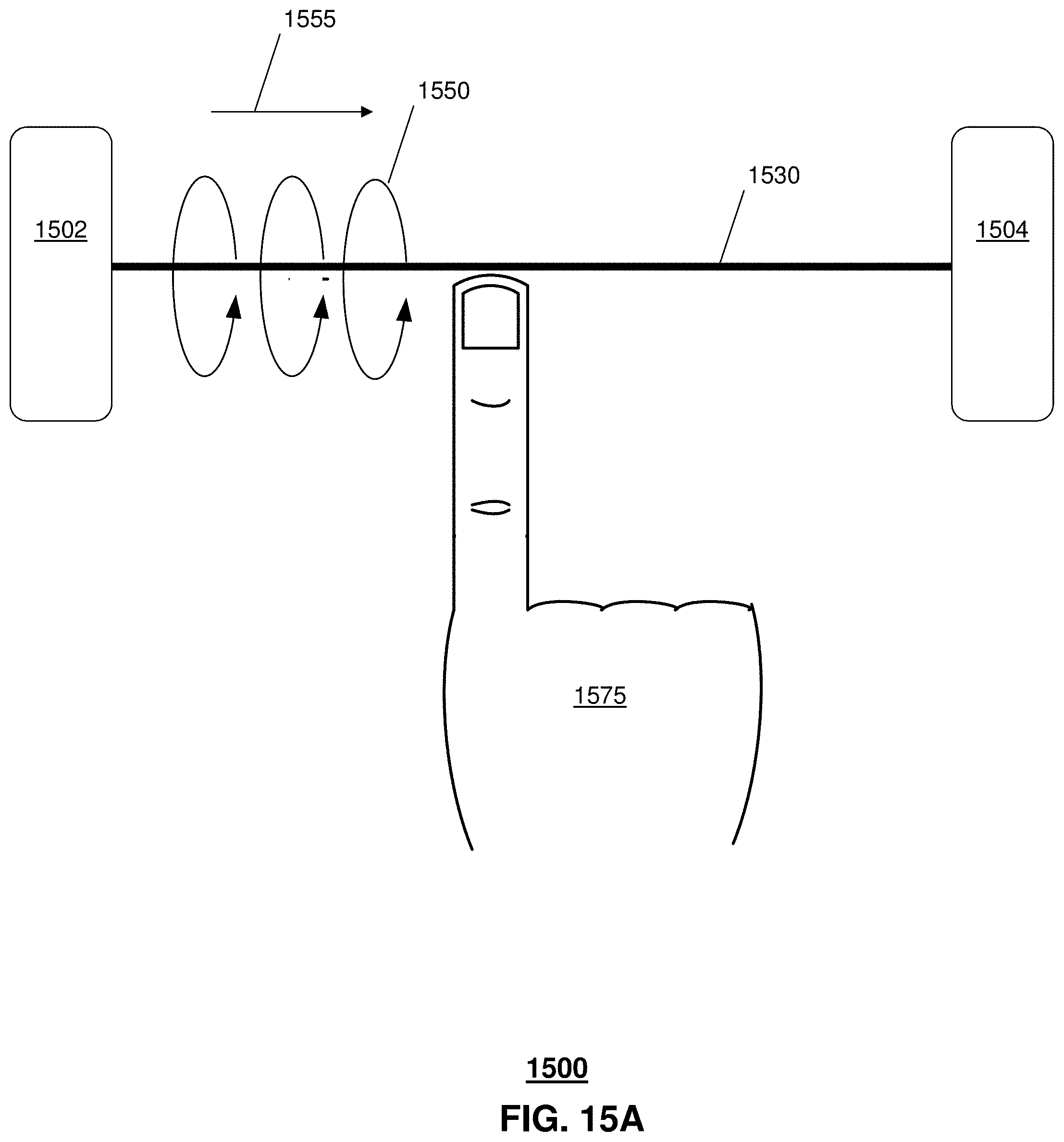
D00013

D00014

D00015
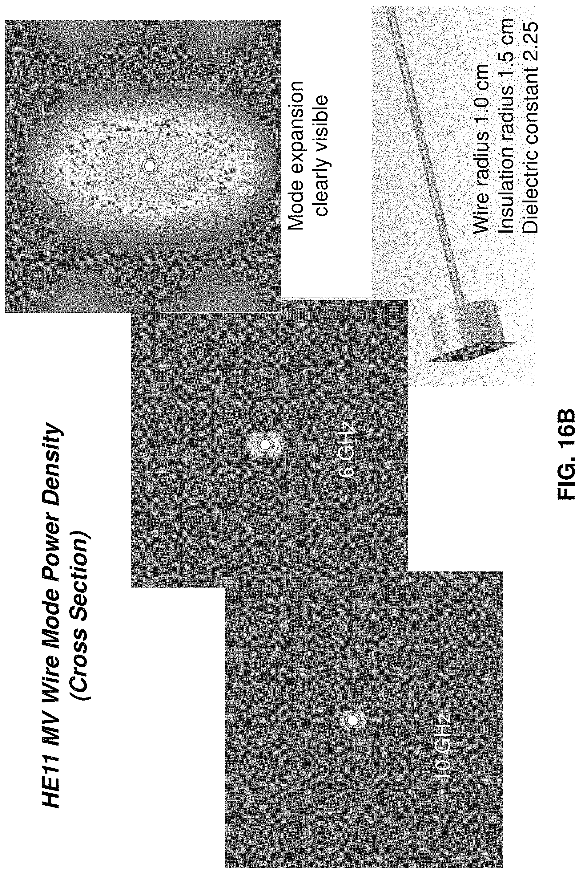
D00016

D00017

D00018
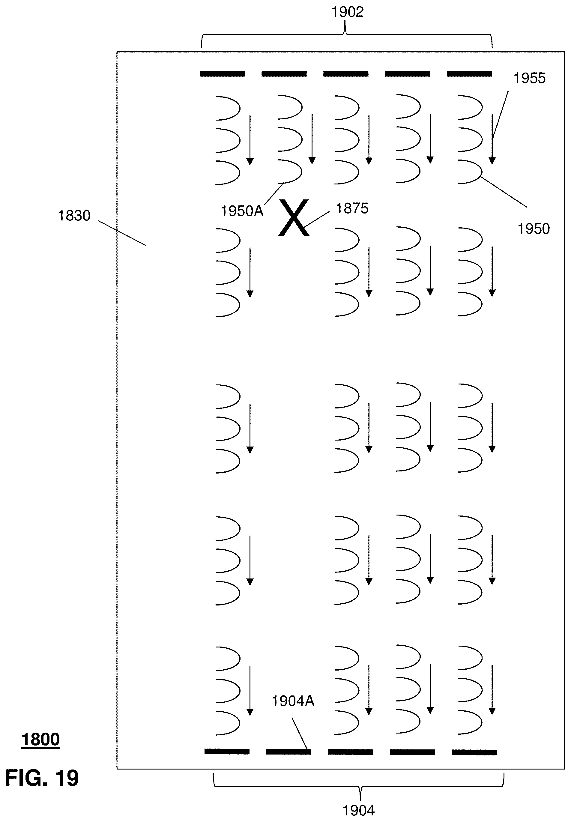
D00019
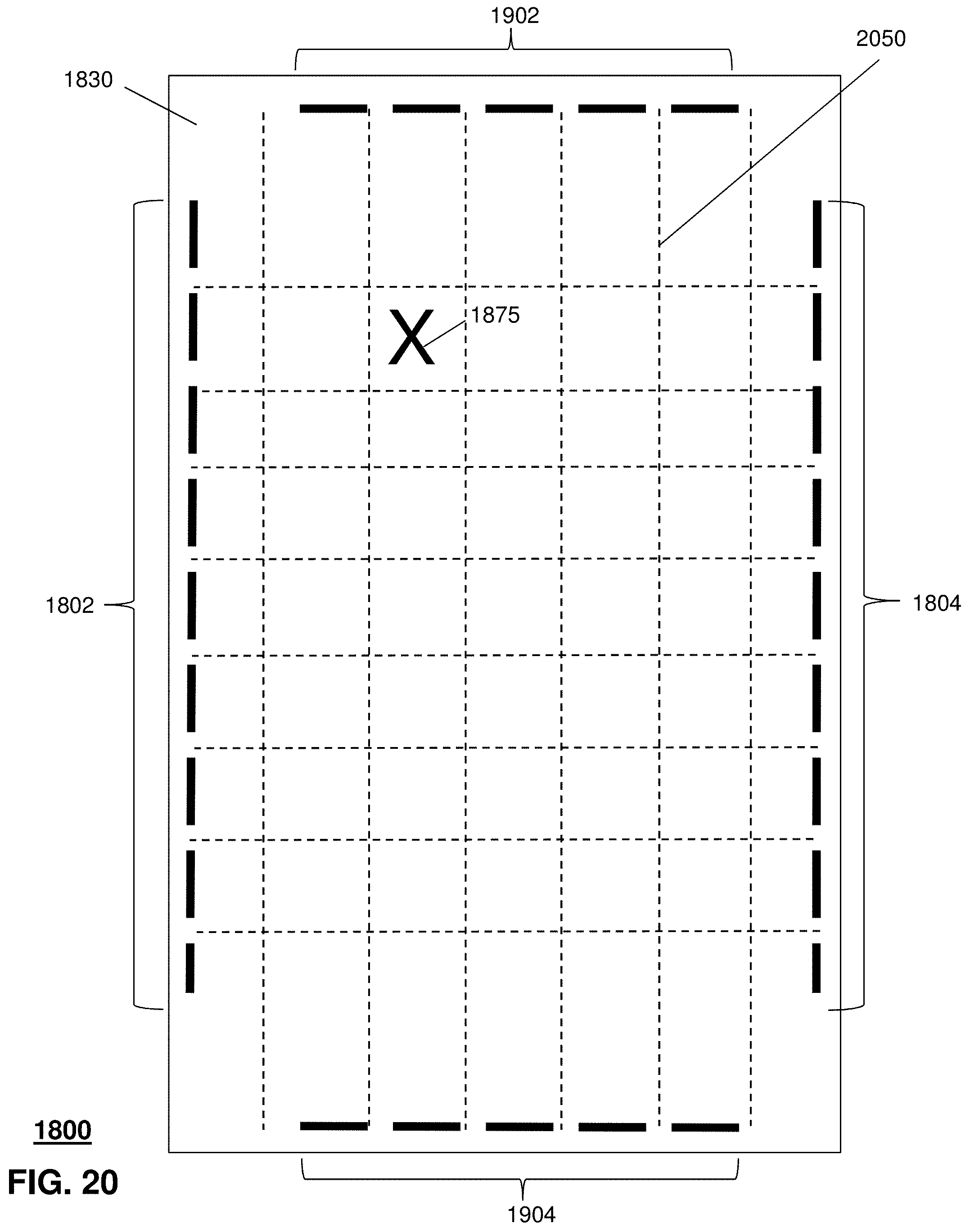
D00020
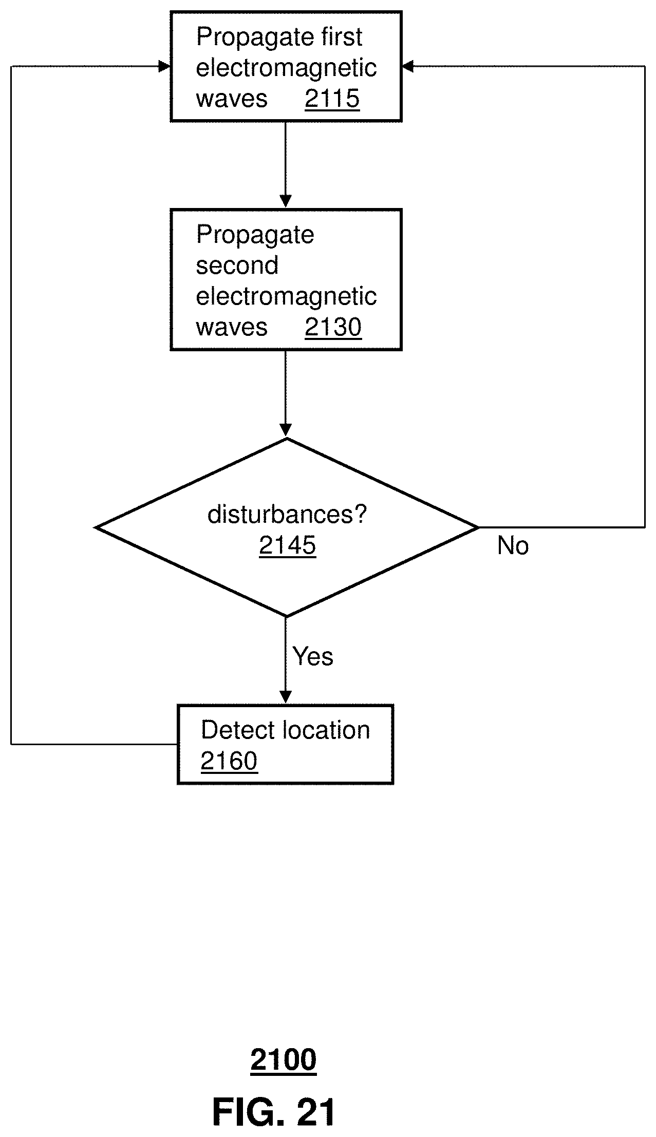
D00021

D00022

D00023

XML
uspto.report is an independent third-party trademark research tool that is not affiliated, endorsed, or sponsored by the United States Patent and Trademark Office (USPTO) or any other governmental organization. The information provided by uspto.report is based on publicly available data at the time of writing and is intended for informational purposes only.
While we strive to provide accurate and up-to-date information, we do not guarantee the accuracy, completeness, reliability, or suitability of the information displayed on this site. The use of this site is at your own risk. Any reliance you place on such information is therefore strictly at your own risk.
All official trademark data, including owner information, should be verified by visiting the official USPTO website at www.uspto.gov. This site is not intended to replace professional legal advice and should not be used as a substitute for consulting with a legal professional who is knowledgeable about trademark law.