Tie wrap for bundling objects
Case , et al. Fe
U.S. patent number 10,549,895 [Application Number 14/745,027] was granted by the patent office on 2020-02-04 for tie wrap for bundling objects. This patent grant is currently assigned to Nita Ize, Inc.. The grantee listed for this patent is Nite Ize, Inc.. Invention is credited to Richard N. Case, Bowden Ormsbee.


View All Diagrams
| United States Patent | 10,549,895 |
| Case , et al. | February 4, 2020 |
Tie wrap for bundling objects
Abstract
A holder includes a body, the body having a first and second receiver and a first and second cylindrical holder. The holder further includes a tie comprised of an elongated piece of shape-retaining deformable material and a cover covering the shape-retaining deformable material along the length of the elongated piece. The covering and the shape-retaining deformable material are bonded along their length. A first portion of the tie passes through the first cylindrical holder. A second portion of the tie passes through the second cylindrical holder, such that a loop is formed between the body and the tie, stretching from the first cylindrical holder to the second cylindrical holder.
| Inventors: | Case; Richard N. (Boulder, CO), Ormsbee; Bowden (Longmont, CO) | ||||||||||
|---|---|---|---|---|---|---|---|---|---|---|---|
| Applicant: |
|
||||||||||
| Assignee: | Nita Ize, Inc. (Boulder,
CO) |
||||||||||
| Family ID: | 47596439 | ||||||||||
| Appl. No.: | 14/745,027 | ||||||||||
| Filed: | June 19, 2015 |
Prior Publication Data
| Document Identifier | Publication Date | |
|---|---|---|
| US 20150284160 A1 | Oct 8, 2015 | |
Related U.S. Patent Documents
| Application Number | Filing Date | Patent Number | Issue Date | ||
|---|---|---|---|---|---|
| 13563562 | Jul 31, 2012 | 9174781 | |||
| 13196725 | Aug 9, 2014 | 8806723 | |||
| 12247523 | Mar 5, 2013 | 8387216 | |||
| Current U.S. Class: | 1/1 |
| Current CPC Class: | B62J 11/00 (20130101); B65D 63/00 (20130101); B29C 45/14565 (20130101); B65D 63/04 (20130101); Y10T 24/149 (20150115); B29L 2031/7276 (20130101) |
| Current International Class: | B65D 63/04 (20060101); B29C 45/14 (20060101); B65D 63/00 (20060101); B62J 11/00 (20060101) |
References Cited [Referenced By]
U.S. Patent Documents
| 757820 | April 1904 | Lykke |
| 1251778 | January 1918 | Humble |
| 1407406 | February 1922 | Glazebrook |
| 1894906 | January 1933 | Henry |
| 2118875 | May 1938 | Windheim |
| 2175036 | October 1939 | Sipe |
| 2224972 | December 1940 | Long et al. |
| 2307808 | January 1943 | Segal |
| 2377688 | June 1945 | Hubbell |
| 2530695 | November 1950 | Helmert |
| 2542601 | February 1951 | Van Cleef |
| D165253 | November 1951 | Ward |
| 2581825 | January 1952 | Ah Fong Lau Ah You |
| 3023483 | March 1962 | Steiner |
| 3214309 | October 1965 | Di Leo et al. |
| 3257054 | June 1966 | Miesel |
| 3426393 | February 1969 | Mead |
| 3458862 | July 1969 | Franks |
| 3543353 | December 1970 | Meehan |
| 3564667 | February 1971 | Patrick, III et al. |
| 3757429 | September 1973 | Sumino |
| 3768711 | October 1973 | Wilkinson |
| 3806358 | April 1974 | Glander et al. |
| 3906139 | September 1975 | Hiraoka et al. |
| 3917387 | November 1975 | Ensing |
| 3930288 | January 1976 | Black et al. |
| 3947927 | April 1976 | Rosenthal |
| 3960302 | June 1976 | Mazzoni, Jr. |
| 3997945 | December 1976 | Robins |
| 4015762 | April 1977 | Mendillo |
| 4120437 | October 1978 | Hara |
| D250631 | December 1978 | Stephenson |
| 4267768 | May 1981 | Cieslak et al. |
| 4463885 | August 1984 | Ball et al. |
| 4483470 | November 1984 | Cousins |
| 4484378 | November 1984 | Kimura et al. |
| 4488748 | December 1984 | Burkes |
| 4524937 | June 1985 | Zizan |
| 4531661 | July 1985 | Santy |
| D280180 | August 1985 | Burt |
| 4540006 | September 1985 | Collis |
| 4553779 | November 1985 | Shortridge |
| 4641454 | February 1987 | Ray et al. |
| 4648414 | March 1987 | Fox et al. |
| 4666417 | May 1987 | Hillman |
| 4679387 | July 1987 | Weidenhaupt et al. |
| 4699303 | October 1987 | Kline |
| 4753355 | June 1988 | Hall et al. |
| 4761053 | August 1988 | Cogelia et al. |
| 4817837 | April 1989 | Grover |
| 4834118 | May 1989 | Goeller |
| 4856689 | August 1989 | Shore |
| 4867478 | September 1989 | Anderson |
| D304270 | October 1989 | Goldman |
| 4897768 | January 1990 | Thul |
| 4915996 | April 1990 | Curry |
| D308205 | May 1990 | Tholberg |
| 4943016 | July 1990 | Hennecke |
| D310909 | October 1990 | Bradtl |
| D317611 | June 1991 | Poe |
| 5054299 | October 1991 | Maveety |
| 5056820 | October 1991 | Des Prez |
| D323826 | February 1992 | Suzuki et al. |
| 5104017 | April 1992 | Vandagriff |
| 5154964 | October 1992 | Iwai et al. |
| 5178354 | January 1993 | Engvall |
| 5190336 | March 1993 | Palz |
| 5199135 | April 1993 | Gold |
| 5234370 | August 1993 | Shapero et al. |
| 5310376 | May 1994 | Mayuzumi et al. |
| 5342687 | August 1994 | Iwai et al. |
| D354620 | January 1995 | King et al. |
| 5390884 | February 1995 | Cambell |
| 5437401 | August 1995 | Seltzer |
| 5468036 | November 1995 | Brown |
| 5498190 | March 1996 | Ganson |
| 5522122 | June 1996 | Turchick et al. |
| D372358 | August 1996 | Mathison |
| 5590422 | January 1997 | Henderson |
| D377798 | February 1997 | Heine |
| 5607748 | March 1997 | Feltman |
| D379542 | May 1997 | Egashira |
| 5664589 | September 1997 | Black |
| 5711143 | January 1998 | Munakata et al. |
| 5714211 | February 1998 | Zinbarg et al. |
| 5769994 | June 1998 | Booz et al. |
| 5787361 | July 1998 | Chen |
| 5788134 | August 1998 | Matic, Jr. |
| D399021 | September 1998 | Lam |
| 5827461 | October 1998 | Feltman |
| 5833188 | November 1998 | Studdiford et al. |
| 5853212 | December 1998 | Daniel |
| 5864924 | February 1999 | Rodriguez |
| 5898975 | May 1999 | Hancock |
| 5916006 | June 1999 | Ganson |
| 5944080 | August 1999 | Podwika |
| D425226 | May 2000 | Galli |
| D426235 | June 2000 | Phirippidis et al. |
| 6081695 | June 2000 | Wallace et al. |
| 6086029 | July 2000 | Oliver |
| 6105923 | August 2000 | Robertson et al. |
| 6113170 | September 2000 | Daniel |
| 6114036 | September 2000 | Rinehart et al. |
| D433642 | November 2000 | Bauman |
| D438536 | March 2001 | Willison et al. |
| 6206187 | March 2001 | Van Winkle |
| 6206542 | March 2001 | Case et al. |
| 6237740 | May 2001 | Weatherall et al. |
| 6332052 | December 2001 | Luther et al. |
| D455419 | April 2002 | Inoue |
| D455815 | April 2002 | Bonzer |
| 6364257 | April 2002 | Holder |
| 6372344 | April 2002 | Castellani et al. |
| D465292 | November 2002 | Ko |
| 6473944 | November 2002 | Vazin |
| 6478282 | November 2002 | Flemming |
| D466287 | December 2002 | Tanaka |
| 6527482 | March 2003 | Stankus |
| 6563927 | May 2003 | Mote et al. |
| 6705497 | March 2004 | Schuett |
| 6742685 | June 2004 | Williams |
| D493280 | July 2004 | Tabata |
| 6785566 | August 2004 | Irizarry |
| D499546 | December 2004 | Smithers |
| 6848663 | February 2005 | Olive |
| D508605 | August 2005 | Hwang et al. |
| 7011879 | March 2006 | Contreras et al. |
| D520526 | May 2006 | Wuest et al. |
| D523022 | June 2006 | Peng |
| D528539 | September 2006 | McClaude |
| D531339 | October 2006 | Lee et al. |
| 7123801 | October 2006 | Fitz |
| D533994 | December 2006 | Hussaini et al. |
| D534004 | December 2006 | Waniga |
| D536116 | January 2007 | Sharrah |
| 7192069 | March 2007 | Daniel |
| 7250213 | July 2007 | Duncan |
| D565290 | April 2008 | Brandenburg et al. |
| 7357540 | April 2008 | Booty, Jr. |
| 7377828 | May 2008 | Cheung |
| D570844 | June 2008 | Liu et al. |
| D574819 | August 2008 | Andre et al. |
| D575056 | August 2008 | Tan |
| D579009 | October 2008 | Su et al. |
| D580437 | November 2008 | Kiyomiya et al. |
| D586795 | February 2009 | Richter |
| D587708 | March 2009 | Yoshida et al. |
| D588735 | March 2009 | Woodard |
| D591044 | April 2009 | Lakhiani |
| 7516575 | April 2009 | Cuccurullo |
| D592341 | May 2009 | Fan |
| D593750 | June 2009 | Song |
| D594224 | June 2009 | Leung et al. |
| D597298 | August 2009 | Lown et al. |
| 7571837 | August 2009 | Orlowski |
| D600852 | September 2009 | Clepper et al. |
| 7609512 | October 2009 | Richardson et al. |
| D603603 | November 2009 | Laine et al. |
| D606311 | December 2009 | Lown et al. |
| D606312 | December 2009 | Lown et al. |
| D606739 | December 2009 | Fahrendorff et al. |
| 7630745 | December 2009 | Chen et al. |
| D609226 | February 2010 | Hofer et al. |
| D609460 | February 2010 | Riccardi |
| D609853 | February 2010 | Salatto-Rose |
| D610135 | February 2010 | Hofer et al. |
| 7661620 | February 2010 | Fields |
| 7673745 | March 2010 | Sirichai et al. |
| 7683275 | March 2010 | Moore et al. |
| D613498 | April 2010 | Tsai |
| D614402 | April 2010 | Lown et al. |
| D615078 | May 2010 | Bradley |
| D616292 | May 2010 | Martinson |
| D616361 | May 2010 | Huang |
| D617093 | June 2010 | Pedersen et al. |
| D619361 | July 2010 | Andre et al. |
| 7757913 | July 2010 | Fichera |
| D620931 | August 2010 | Opman |
| D622429 | August 2010 | Jones |
| D623180 | September 2010 | Diebel |
| D625303 | October 2010 | Kim |
| D628534 | December 2010 | Daniel |
| D628798 | December 2010 | Kalbach |
| D629404 | December 2010 | Wu et al. |
| D630848 | January 2011 | Long et al. |
| D630936 | January 2011 | Carney |
| D631058 | January 2011 | Chin et al. |
| 7861981 | January 2011 | Olver |
| 7901148 | March 2011 | Zunker |
| D635555 | April 2011 | Giles |
| D637592 | May 2011 | Magness et al. |
| D638005 | May 2011 | Richardson et al. |
| D638828 | May 2011 | Melanson et al. |
| D641974 | July 2011 | Stampfli |
| 7980435 | July 2011 | Tages |
| D643029 | August 2011 | Feng |
| D644168 | August 2011 | Bishay et al. |
| D644428 | September 2011 | Feng |
| 8033678 | October 2011 | Patterson |
| D648332 | November 2011 | Kim et al. |
| D649347 | November 2011 | Smith et al. |
| D649537 | November 2011 | Magness et al. |
| D649539 | November 2011 | Hong |
| D650371 | December 2011 | Wibby et al. |
| D651204 | December 2011 | Wibby et al. |
| D652825 | January 2012 | Bau |
| D654069 | February 2012 | Kwon et al. |
| D654914 | February 2012 | Martin |
| D655081 | March 2012 | Maravilla et al. |
| D657782 | April 2012 | Biller |
| D658169 | April 2012 | Mo |
| D660857 | May 2012 | Emami |
| 8204561 | June 2012 | Mongan et al. |
| D662925 | July 2012 | Mayberry et al. |
| D663263 | July 2012 | Gupta et al. |
| D663725 | July 2012 | Polito |
| 8245842 | August 2012 | Bau |
| 8246268 | August 2012 | Dratewski |
| D669062 | October 2012 | Rothbaum et al. |
| D669618 | October 2012 | Ormsbee et al. |
| D669619 | October 2012 | Ormsbee et al. |
| 8286789 | October 2012 | Wilson et al. |
| 8297440 | October 2012 | Schmidt et al. |
| D670279 | November 2012 | Veltz et al. |
| 8316611 | November 2012 | Ellis et al. |
| D672735 | December 2012 | Barley et al. |
| D672754 | December 2012 | Inada |
| D675014 | January 2013 | Adelman et al. |
| 8356736 | January 2013 | Musgrave |
| D675605 | February 2013 | Adelman et al. |
| D675606 | February 2013 | Adelman et al. |
| D676841 | February 2013 | Magness et al. |
| D678755 | March 2013 | Weidemann et al. |
| 8387216 | March 2013 | Martinson |
| D679701 | April 2013 | Adelman et al. |
| 8428664 | April 2013 | Wyers |
| D681612 | May 2013 | Palacios |
| D683136 | May 2013 | Wilson et al. |
| D684358 | June 2013 | Pegg |
| D685990 | July 2013 | Zhang |
| 8478357 | July 2013 | Harrington |
| D690292 | September 2013 | Bibla et al. |
| 8616422 | December 2013 | Adelman et al. |
| 2002/0028336 | March 2002 | Jaccoud |
| 2002/0118535 | August 2002 | Nostrant |
| 2003/0019894 | January 2003 | Caldana |
| 2003/0103624 | June 2003 | Hu |
| 2004/0089688 | May 2004 | Perez |
| 2005/0035161 | February 2005 | Shioda |
| 2005/0057921 | March 2005 | Menosky |
| 2005/0093205 | May 2005 | Martin et al. |
| 2005/0211357 | September 2005 | Ren |
| 2005/0274211 | December 2005 | Edgman |
| 2005/0274425 | December 2005 | Ostrander et al. |
| 2006/0058070 | March 2006 | Chang |
| 2008/0096620 | April 2008 | Lee et al. |
| 2008/0124544 | May 2008 | Alexander et al. |
| 2008/0127460 | June 2008 | Severen et al. |
| 2008/0223389 | September 2008 | Harvie |
| 2008/0254281 | October 2008 | Chen et al. |
| 2009/0000086 | January 2009 | Bing |
| 2009/0045310 | February 2009 | Koesema, Jr. |
| 2009/0095854 | April 2009 | Wilbur et al. |
| 2009/0140016 | June 2009 | Case et al. |
| 2010/0021155 | January 2010 | Orzeck et al. |
| 2010/0059649 | March 2010 | Buxton |
| 2010/0115732 | May 2010 | Honeycutt |
| 2010/0203931 | August 2010 | Hynecek et al. |
| 2010/0224519 | September 2010 | Kao |
| 2010/0294908 | November 2010 | Mish et al. |
| 2010/0300909 | December 2010 | Hung |
| 2011/0031287 | February 2011 | Le Gette et al. |
| 2011/0073608 | March 2011 | Richardson et al. |
| 2011/0228459 | September 2011 | Richardson et al. |
| 2011/0286217 | November 2011 | Martinson et al. |
| 2012/0088558 | April 2012 | Song |
| 2012/0175474 | July 2012 | Barnard et al. |
| 2013/0026316 | January 2013 | Case et al. |
| 2013/0032617 | February 2013 | Adelman et al. |
| 2013/0118932 | May 2013 | Green et al. |
| 2013/0174382 | July 2013 | Martinson |
| 87100561 | Aug 1988 | CN | |||
| 201072035 | Jun 2008 | CN | |||
| 201137823 | Oct 2008 | CN | |||
| 101523112 | Sep 2009 | CN | |||
| 201530531 | Jul 2010 | CN | |||
| 102498316 | Jun 2012 | CN | |||
| 2004000405 | Jan 2004 | JP | |||
| 2004-238038 | Aug 2004 | JP | |||
| 2004-320987 | Nov 2004 | JP | |||
| 100988204 | Oct 2010 | KR | |||
| WO 2010/138381 | Dec 2010 | WO | |||
Other References
|
First Office Action by China Patent Office dated Oct. 25, 2016 as to counterpart App. 201380050829.6 (w/English translation) (23 pages). cited by applicant . Second Office Action by China Patent Office dated Apr. 12, 2017 as to counterpart App. 201180073958.8 (w/English translation) (21 pages). cited by applicant . In the U.S. Appl. No. 12/247,523 Final Office Action dated Aug. 16, 2012, 11 pages. cited by applicant . In the U.S. Appl. No. 12/247,523 Non-Final Office Action dated Jan. 31, 2012, 7 pages. cited by applicant . In the U.S. Appl. No. 12/247,523 Non-Final Office Action dated Jul. 13, 2011, 9 pages. cited by applicant . In the U.S. Appl. No. 13/196,725 Non-Final Office Action dated Dec. 3, 2013, 6 pages. cited by applicant . In the U.S. Appl. No. 13/196,762 Non-Final Office Action dated Mar. 26, 2013, 13 pages. cited by applicant . In the U.S. Appl. No. 13/563,562 Non-Final Office Action dated Oct. 6, 2014, 8 pages. cited by applicant . In the U.S. Appl. No. 13/784,455 Final Office Action dated Nov. 8, 2013, 11 pages. cited by applicant . In the U.S. Appl. No. 13/784,455 Non-Final Office Action dated May 22, 2013, 9 pages. cited by applicant . In the U.S. Appl. No. 13/968,181 Non-Final Office Action dated Oct. 3, 2014, 5 pages. cited by applicant . In the U.S. Appl. No. 29/433,070 Non-Final Office Action dated Mar. 24, 2014, 7 pages. cited by applicant . Acor Volara 4E foam padding, <URL:http://www.acor.com/volara.htm>, retrieved from Internet on Nov. 15, 2012. cited by applicant . ACOR, ACOR present Volara 4E, Mar. 2, 2008; http://acor.com/volara.htm. cited by applicant . Cruzerlite Razr Maxx case review, posted on Oct. 3, 2012, <URL:http://forums.androidcentral.com/droid-razr-maxx/213784-cruzerlit- e-razr-maxx-case-review.html>, retrieved from Internet on Nov. 14, 2012. cited by applicant . International Search Report dated Oct. 18, 2012, in co-pending PCT Application No. PCT/US12/49309, 4 pages. cited by applicant . Nite Ize Connect Case for iPhone, Published on Aug. 17, 2012, by Nite Ize, Inc. <URL:http://www.youtube.com/watch?v=4LDiXufkDgY>, retrieved from Internet on Nov. 14, 2012. cited by applicant . Nite Ize Connect Mobile Mount, Posted Aug. 10, 2012, by Daniel Turk,<URL:http://www.maclife.com/article/reviews/best_case_scenario_ni- te_ize_connect_case_and_mobile_mount>, retrieved from Internet on Nov. 14, 2012. cited by applicant . Web page illustration from web site illustrating Grip Twist lock and carry device; griptwist.com; Dakota Trading corporation, 2008. cited by applicant . Web page illustration from web site illustrating reusable silicone coated Sili Twists; www.wrapables.com; Wrapables, 2008. cited by applicant . Office Action dated Sep. 18, 2017 issued in parallel Chinese patent application No. 201180073958.8 (38 pages with English translation). cited by applicant . Office Action dated Mar. 26, 2019 issued in co-pending Chinese Patent App. No. 201810448674.6. cited by applicant. |
Primary Examiner: Sandy; Robert
Assistant Examiner: Mercado; Louis A
Attorney, Agent or Firm: Haynes and Boone, LLP
Parent Case Text
CROSS REFERENCE TO RELATED APPLICATIONS
This application is a continuation of U.S. patent application Ser. No. 13/563,562 filed Jul. 31, 2012, now U.S. Pat. No. 9,174,781 issued Nov. 3, 2015, which is a continuation-in-part of U.S. patent application Ser. No. 13/196,725 filed Aug. 2, 2011, now U.S. Pat. No. 8,806,723 issued Aug. 19, 2014, which is a continuation-in-part of U.S. patent application Ser. No. 12/247,523 filed Oct. 8, 2008, now U.S. Pat. No. 8,387,216 issued Mar. 5, 2013, entitled "TIE WRAP FOR BUNDLING OBJECTS." The foregoing applications are hereby incorporated by reference to the same extent as though fully disclosed herein.
Claims
What is claimed as new and desired to be protected by Letters Patent of the United States is:
1. A twist tie device comprising: an elongated piece of shape-retaining deformable material; a cover covering the elongated piece of shape-retaining deformable material, the cover and the shape-retaining deformable material being bonded; an outer cover covering the cover, the outer cover and the cover being bonded; and end caps formed beyond a length of the elongated piece of shape-retaining deformable material, wherein the end caps are made from a same material as the outer cover, wherein a diameter of the end caps is greater than a diameter of the outer cover and the end caps include a ridge that is at a right angle between the outer cover and the end caps, wherein the right angle is configured to catch against surfaces providing enhanced holding.
2. The twist tie device of claim 1, wherein the end caps are injection molded.
3. The twist tie device of claim 2, wherein the end caps and outer cover are bonded to the elongated piece of shape-retaining deformable material.
4. The twist tie device of claim 1, wherein the outer cover includes a gripping area.
5. The twist tie device of claim 4, wherein the gripping area includes ribs.
6. The twist tie device of claim 5, wherein the ribs run the length of the elongated piece of shape-retaining deformable material.
7. A twist tie device comprising: an elongated piece of shape-retaining deformable material; a cover covering the elongated piece of shape-retaining deformable material, the cover and the shape-retaining deformable material being bonded; an outer cover covering the cover, the outer cover and the cover being bonded; and end caps formed beyond a length of the elongated piece of shape-retaining deformable material, wherein a diameter of the end caps is greater than a diameter of the outer cover and the end caps include a ridge that is at a right angle between the outer cover and the end caps, wherein the right angle is configured to catch against surfaces providing enhanced holding.
8. The twist tie device of claim 7, wherein the outer cover includes a gripping area.
9. The twist tie device of claim 8, wherein the gripping area includes ribs.
10. The twist tie device of claim 8, wherein the gripping area is a texturized surface.
11. The twist tie device of claim 8, wherein the gripping area includes ribs that are extruded as part of the outer cover.
12. The twist tie device of claim 9, wherein the ribs run a length of the elongated piece of shape-retaining deformable material.
13. The twist tie device of claim 9, wherein the ribs are in a shape of a curve.
14. The twist tie device of claim 9, wherein the ribs are in a shape of a weave.
15. The twist tie device of claim 7, wherein the end caps are made from a same material as the outer cover.
16. The twist tie device of claim 15, wherein the end caps are injection molded.
17. The twist tie device of claim 16, wherein the end caps and outer cover are bonded to the elongated piece of shape-retaining deformable material.
18. A twist tie device comprising: an elongated piece of shape-retaining deformable material; a cover bonded to the elongated piece of shape-retaining deformable material; an outer cover bonded to the cover; and end caps formed beyond a length of the elongated piece of shape-retaining deformable material, wherein a diameter of the end caps is greater than a diameter of the outer cover, wherein the bonded of the cover to the elongated piece of shape-retaining deformable material prevents the elongated piece of shape-retaining deformable material from exiting the cover and entirety of the elongated piece of shape-retaining deformable material is straightened, wherein a right angle between the outer cover and the end caps is configured to catch against surfaces providing enhanced holding.
Description
BACKGROUND
Twist ties are well known in the art and typically are not suitable for supporting weight or bundling large objects. Twist ties often are found on packaging such as bread wrappers. These twist ties are usually a plastic or paper coating that covers a wire within the twist tie. The plastic or paper coating is not bonded to the wire and may be removed easily. Also, the coating provides little grip to the object on which the twist tie is wrapped. The coating does not grip itself well either.
U.S. Pat. No. 6,113,170 shows a wrap for bundling objects that includes a wire covered by a flexible tube, but there is no bonding between the wire and the tube. The invention of that patent also lacks a surface which enhances the grip of the wrap when it is wrapped around itself or other objects.
SUMMARY
Embodiments and configurations including a twist tie device are shown herein. The device has an elongated piece of shape-retaining deformable material. A cover covers the shape-retaining deformable material along the length of the elongated piece. The cover has a bond between the elongated piece and the cover. The bond between the cover and the elongated piece is along the entire interior surface of the cover. An outer cover may be bonded to the cover.
The outer cover may have a gripping surface and a non-gripping surface. The gripping surface will provide more grip for the twist tie device when it is wrapped around itself, and the gripping surface will provide more grip when it is wrapped around objects. A non-gripping surface being generally smoother than the gripping surface is suitable for containing indicia.
In one embodiment, a method of making a twist tie device includes providing an elongated piece of shape-retaining deformable material and heating the shape-retaining deformable material. The method includes coextruding a cover to surround the elongated piece of shape-retaining deformable material so that a bond is formed between the shape-retaining deformable material and the cover. The method includes injection molding an end cap beyond a length of the elongated piece of shape-retaining deformable material.
In one embodiment, a holder includes a body and a cylindrical holder interconnected with the body. The holder further includes a tie comprised of an elongated piece of shape-retaining deformable material and a cover covering the shape-retaining deformable material along the length of the elongated piece; the covering and the shape-retaining deformable material being bonded along their length; the tie located in the cylindrical holder; and the cylindrical holder having a first circular cross-section approximately equal to a second circular cross-section of the tie. Optionally, the cylindrical holder includes an aperture along a length of the cylindrical holder, the aperture more narrow than a width of the tie, such that when compressed the tie may be moved through the aperture releasing it from the cylindrical holder. Alternatively, the body includes a slot for receiving a clip. In one alternative, the body is integrated into the housing of an object. Optionally, the body includes a connection mechanism for attaching to another object. In one alternative, a plurality of cylindrical holders is attached to the body, the cylindrical holder being one of the plurality of cylindrical holders. Optionally, the body has a first and second edge; the first and second edge opposite each other and parallel to each other; the cylindrical holder located on the first edge; the cylindrical holder having a first length parallel to the first circular cross section; the first length of the cylindrical holder parallel to the first edge; a second cylindrical holder of the plurality of cylindrical holders located on the second edge; the second cylindrical holder having a third circular cross-section and a second length parallel to the third circular cross section; and the second length of the second cylindrical holder parallel to the second edge. Alternatively, the tie is located in the second cylindrical holder and a first portion of the tie stretches between the cylindrical holder and the second cylindrical holder; a second portion of the tie extends from the cylindrical holder opposite the first portion; and a third portion of the tie extends from the second cylindrical holder opposite the first portion. Optionally, the first portion of the tie is bent away from the body in order to form a support structure in conjunction with the body. In one alternative, the second and third portions of the tie are bent approximately perpendicular from the body for insertion into a gap. In another alternative, the gap is a vent of a car. Optionally, the body has a first and second side; the first and second sides are opposite each other; the cylindrical holder is located on the first side; the cylindrical holder having a first length parallel to the first circular cross section; a second cylindrical holder of the plurality of cylindrical holders located on the second side; the second cylindrical holder having a third circular cross-section and a second length parallel to the third circular cross section; and the second length of the second cylindrical holder parallel to the first length of the cylindrical holder. Alternatively, the body includes a cavity for a lighting module. Optionally, the holder further includes a cap configured to cover the cavity. Alternatively, a third side of the body opposite the cap is curved to mimic the shape of a bar. Optionally, the bar is part of a bike.
In another embodiment, an attachable lighting device includes a lighting device having a body and an aperture in the body. The attachable lighting device further includes a tie comprised of an elongated piece of shape-retaining deformable material and a cover covering the shape-retaining deformable material along the length of the elongated piece; the covering and the shape-retaining deformable material being bonded along their length; and the tie attached to the lighting device via the aperture wherein the tie is coiled around itself after passing through the aperture.
In one embodiment, a holder includes a body, the body having a first and second receiver and a first and second cylindrical holder. The holder further includes a tie comprised of an elongated piece of shape-retaining deformable material and a cover covering the shape-retaining deformable material along the length of the elongated piece. The covering and the shape-retaining deformable material are bonded along their length. A first portion of the tie passes through the first cylindrical holder. A second portion of the tie passes through the second cylindrical holder, such that a loop is formed between the body and the tie, stretching from the first cylindrical holder to the second cylindrical holder. Optionally, the first and second cylindrical holders each include an aperture along a length of the cylindrical holder with the aperture narrower than a width of the tie such that, when compressed, the tie may be moved through the aperture releasing it from the cylindrical holder. Alternately, the holder includes a second tie, a first portion of the second tie passing through a third cylindrical holder in the body, a second portion of the second tie passing through a fourth cylindrical holder in the body, such that a second loop is formed between the body and the second tie, stretching from the third cylindrical holder to the fourth cylindrical holder. Alternatively, the first receiver is configured to receive a flashlight and the first receiver is located on the body such that it is a portion of the loop formed between the body and the tie. In one configuration, the second receiver is on an opposite side of the body from the first receiver. Optionally, the second receiver is configured to receive a set of bicycle handle bars. Alternatively, a third and fourth portion of the tie are positioned on opposite the loop and are twisted to secure the second receiver to the bicycle hand bars. Optionally, the first and second receivers have a shape approximately resembling a horizontal cylinder segment, wherein horizontal refers to a direction of the length of the horizontal cylinder segment. In one alternative, the horizontal cylinder segment of the first receiver is perpendicular to the horizontal cylinder segment of the second receiver. Optionally, the covering of the tie provides for sufficient friction to effectively hold the holder to the bicycle handle bars and flashlight during normal usage.
In one embodiment, a connection device, for connecting a flashlight to another object, the connection device includes a body having a first and second receiver and a first, second, third, and fourth aperture located in the body. The connection device further includes first and second tie, the first tie passing through the first and second aperture, the second tie passing through the third and fourth aperture such that a first loop is formed on a first side of the body where the first receiver is located and a second loop is formed on the first side of the body where the first receiver is located. The first and second end of the first tie extends beyond a second side of the body where the second receiver is located and a first and second end of the second tie extends beyond the second side of the body where the second receiver is located. Optionally, wherein the first and second receivers have a shape approximately resembling a horizontal cylinder segment, wherein horizontal refers to a direction of the length of the horizontal cylinder segment. Alternatively, the horizontal cylinder segment of the first receiver is perpendicular to the horizontal cylinder segment of the second receiver. Optionally, the first receiver is configured to receive a flashlight the second receiver is configured to receive a set of bicycle handle bars. Alternatively, first and second end of the first and second tie are twisted to secure the second receiver to the bicycle hand bars. Optionally, the first and second tie are comprised of an elongated piece of shape-retaining deformable material and a cover covering the shape-retaining deformable material along the length of the elongated piece; the covering and the shape-retaining deformable material being bonded along their length.
BRIEF DESCRIPTION OF THE DRAWINGS
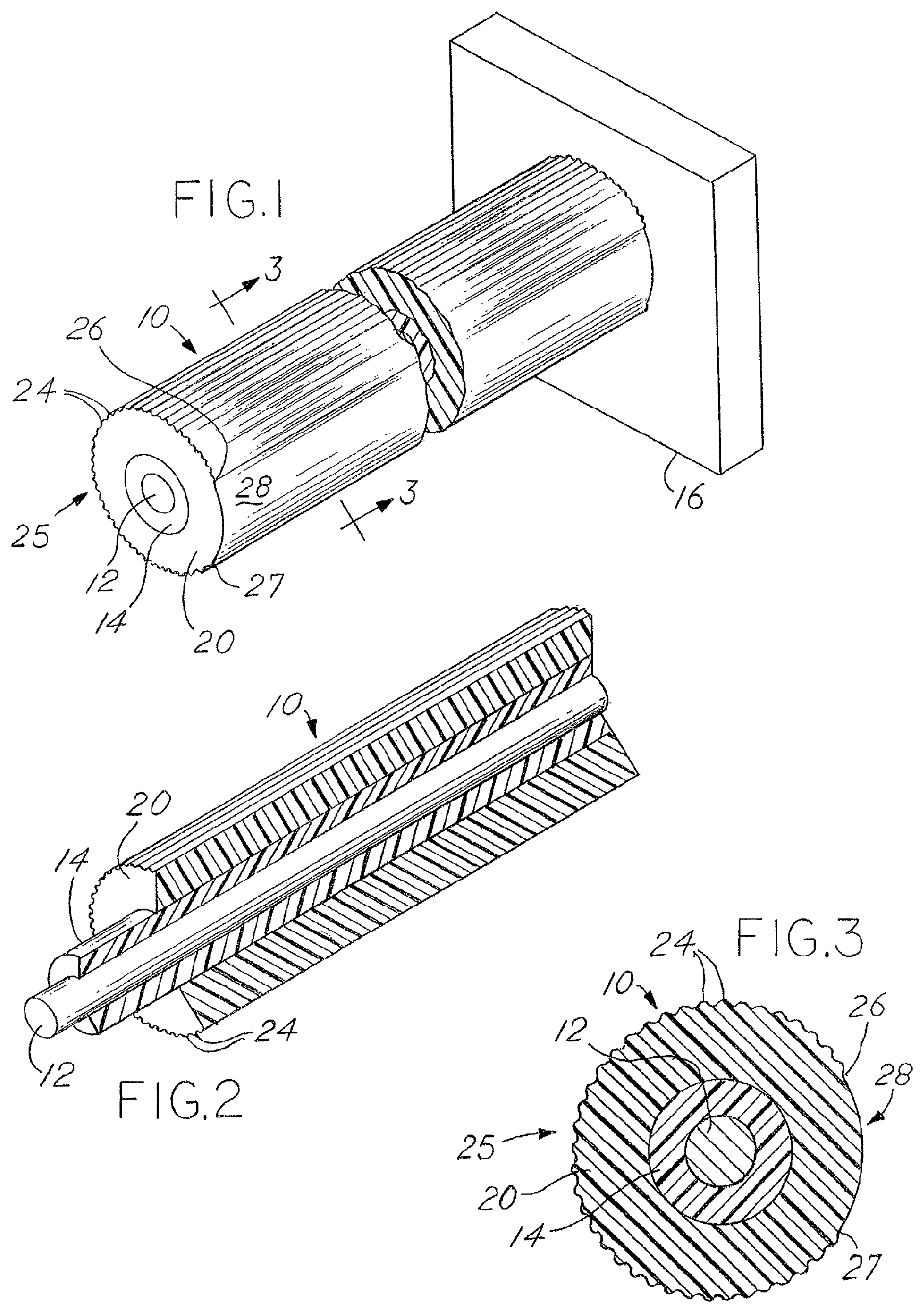
FIG. 1 is a perspective sectional view of the twist tie device;
FIG. 2 is a perspective sectional view of the device shown in FIG. 1;
FIG. 3 is a sectional view taken about the line 3-3 in FIG. 1;
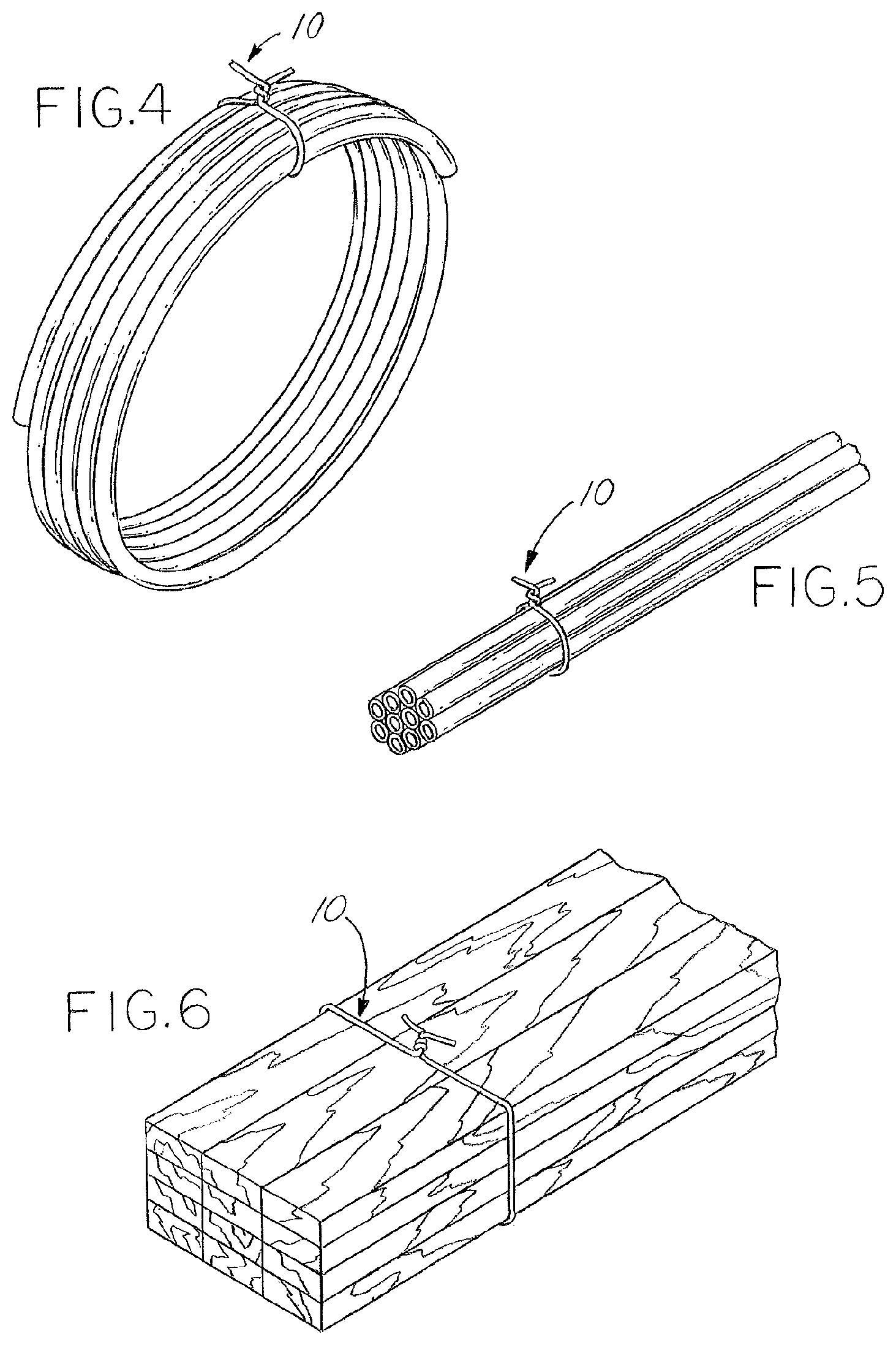
FIGS. 4-6 show embodiments of a twist tie used to bundle various objects;
FIG. 7 shows an embodiment of a lighting device with integrated twist ties;
FIG. 8A shows a cross-section of the body of the lighting device of FIG. 7;
FIG. 8B shows a top view of the body of the lighting device of FIG. 7;
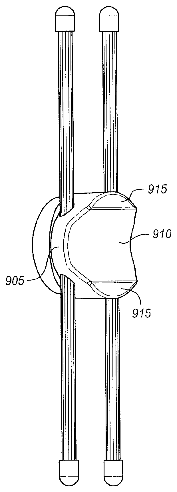
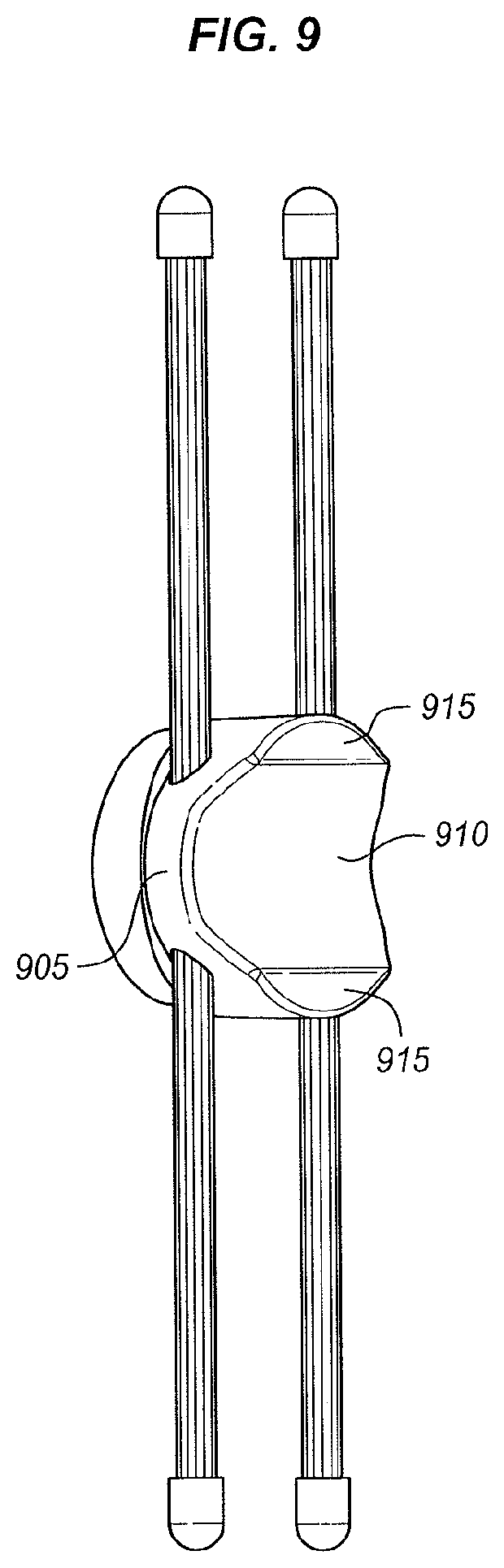
FIG. 9 shows a back view of the body of the lighting device of FIG. 7;
FIG. 10 shows the lighting device of FIG. 7 on a tube;
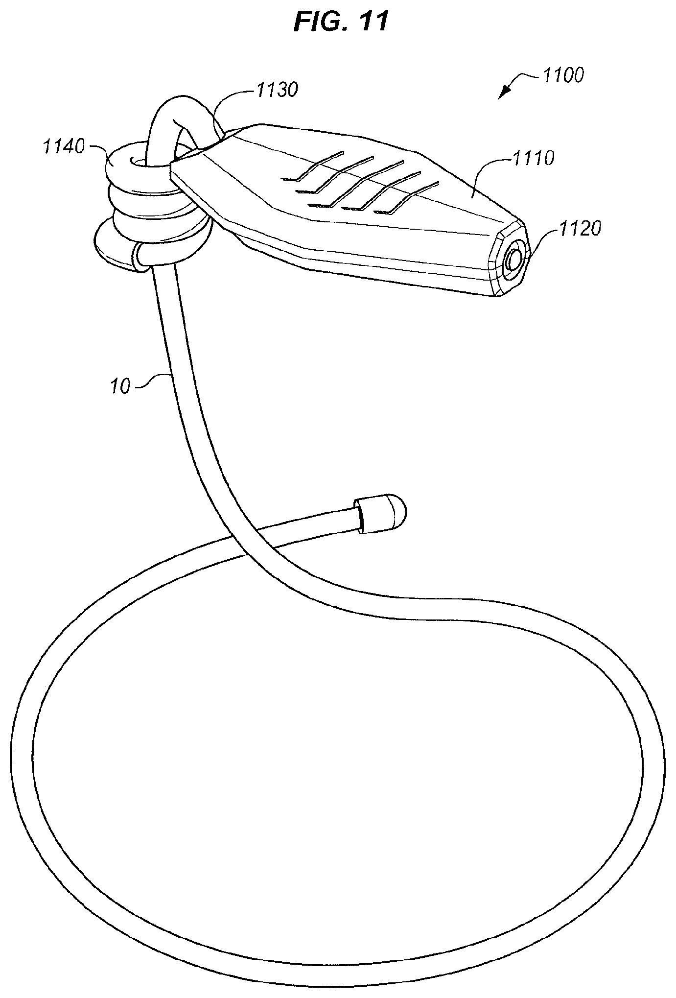
FIG. 11 shows an embodiment of the twist tie integrated with a lighting device;
FIG. 12 shows an embodiment of a receiving attachment including twist ties for insertion into the vent of a vehicle;
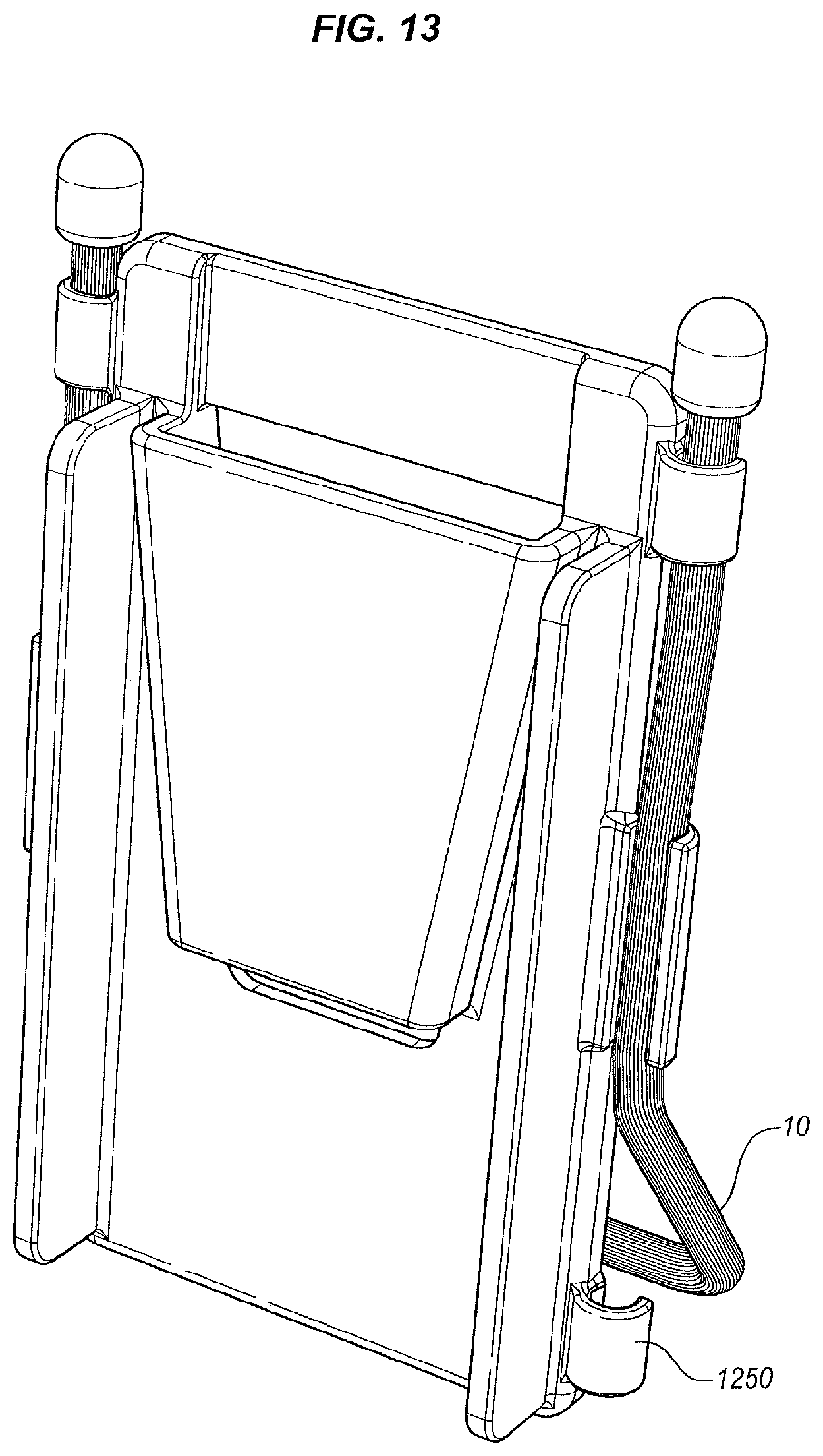
FIG. 13 shows the receiving attachment of FIG. 12 arranged as a stand;
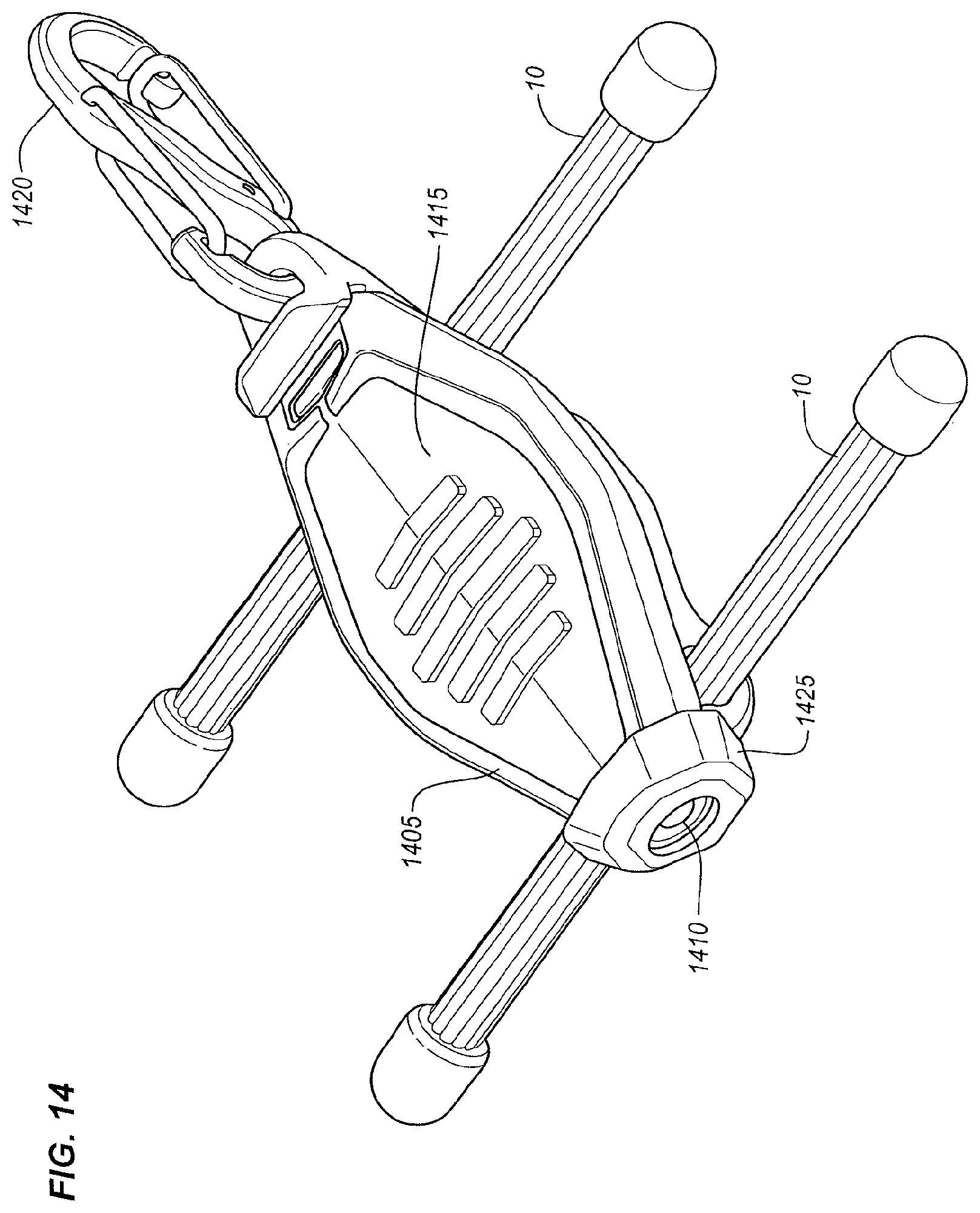
FIG. 14 shows a top perspective view of an embodiment of a lighting device incorporating ties;
FIG. 15 shows a bottom perspective view of the lighting device of FIG. 14;
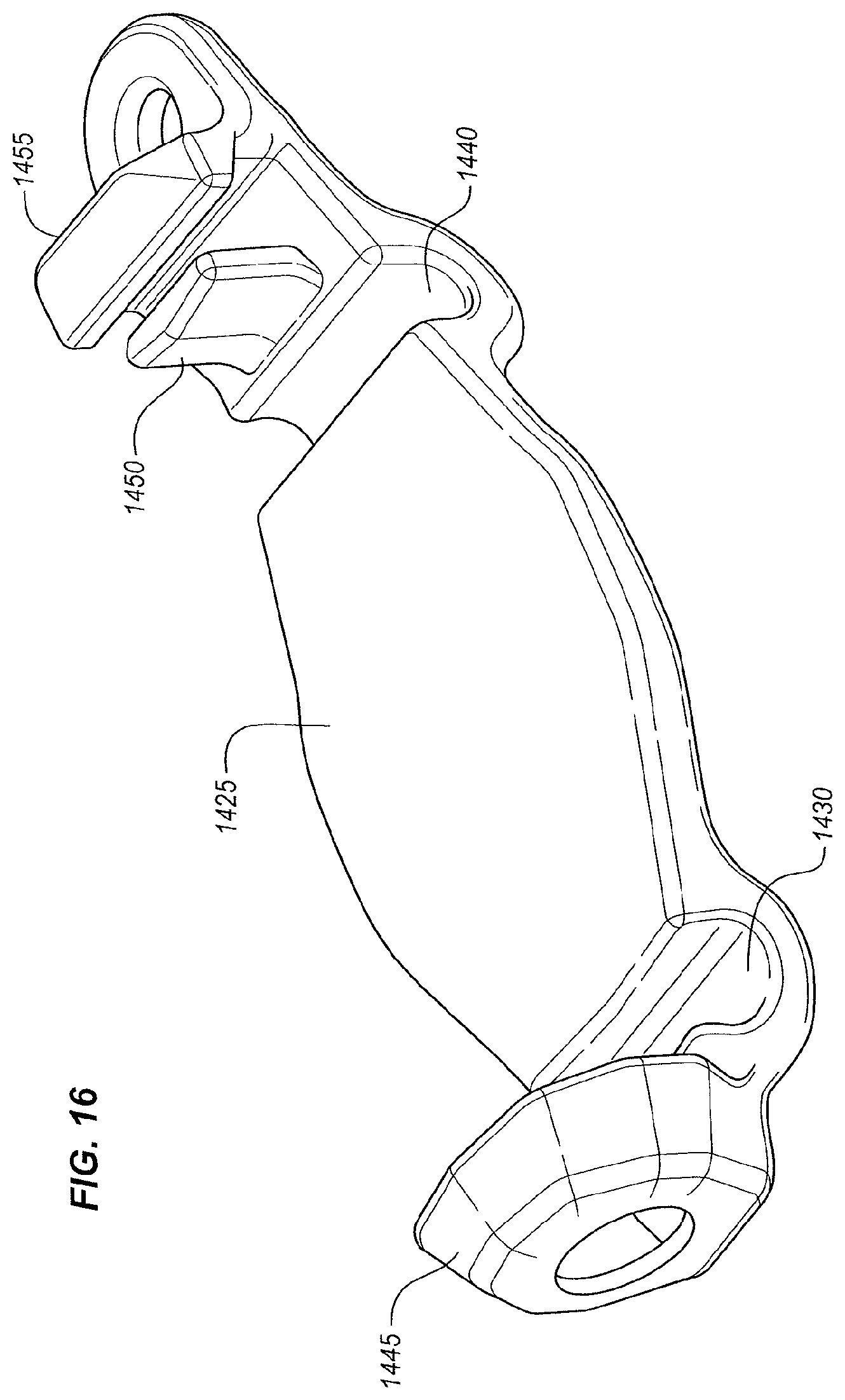
FIG. 16 shows a lower body portion of the lighting device of FIG. 14;
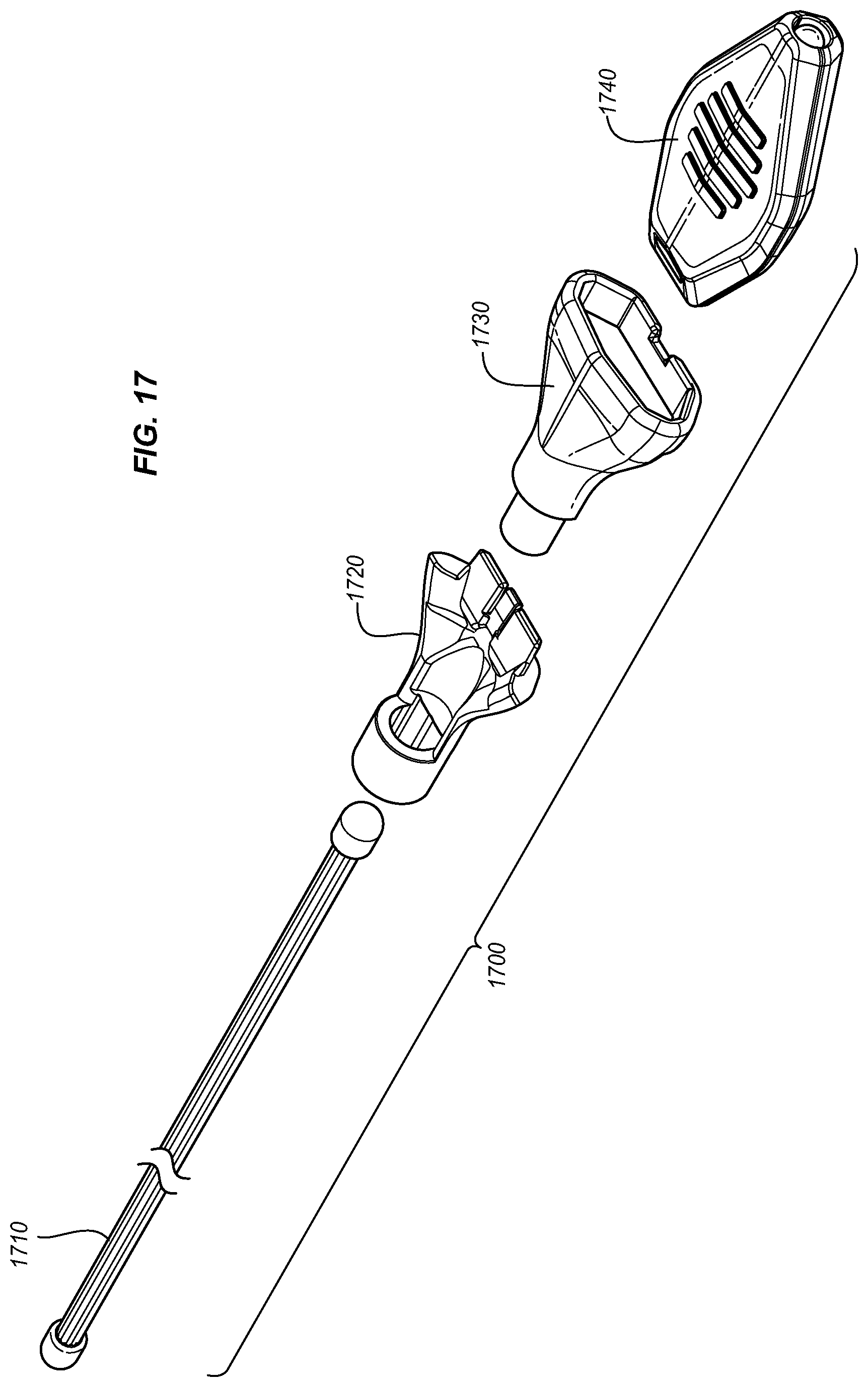
FIG. 17 shows a top perspective view of one embodiment of a lighting device;
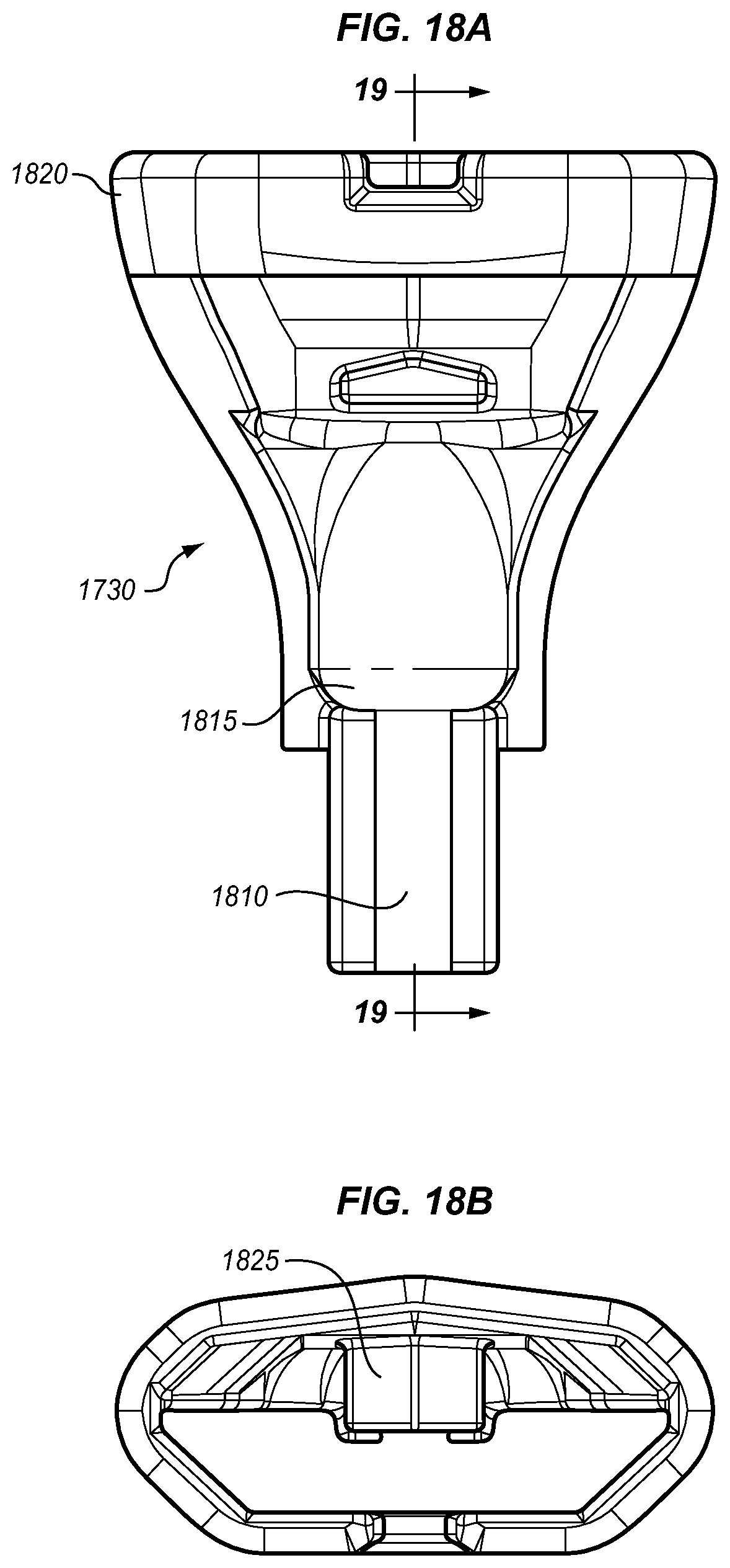
FIG. 18A shows a side view of one-half of a connection device of the lighting device of FIG. 17;
FIG. 18B shows a front view of one-half of the connection device of the lighting device of FIG. 17;
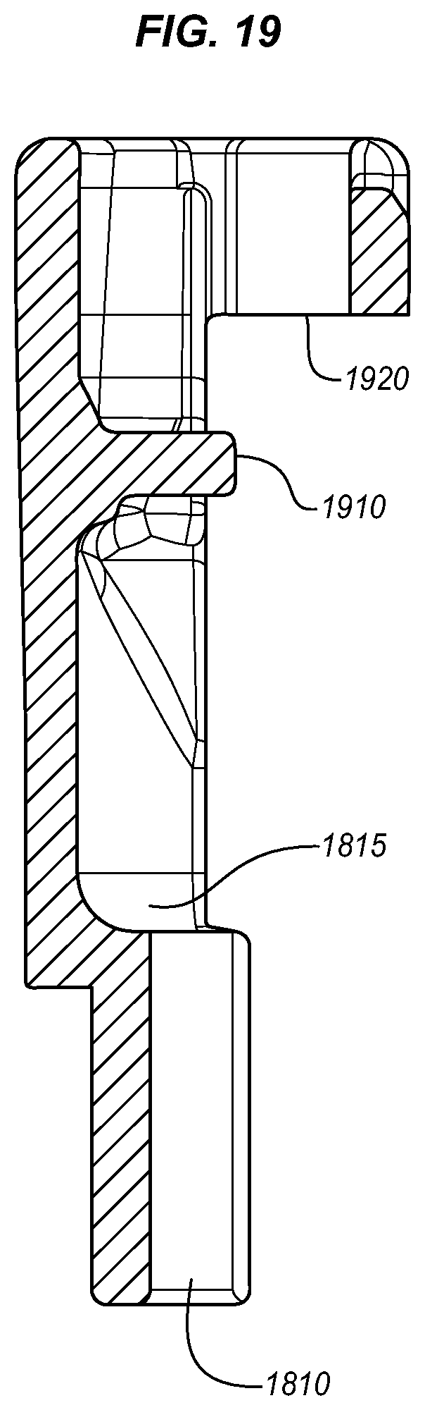
FIG. 19 shows a cross section of one-half of the connection device of the lighting device of FIG. 17;
FIG. 20A shows a side view of the other half of a connection device of the lighting device of FIG. 17;
FIG. 20B shows a front view of the other half of the connection device of the lighting device of FIG. 17;
FIG. 21 shows a cross section of the other half of the connection device of the lighting device of FIG. 17;
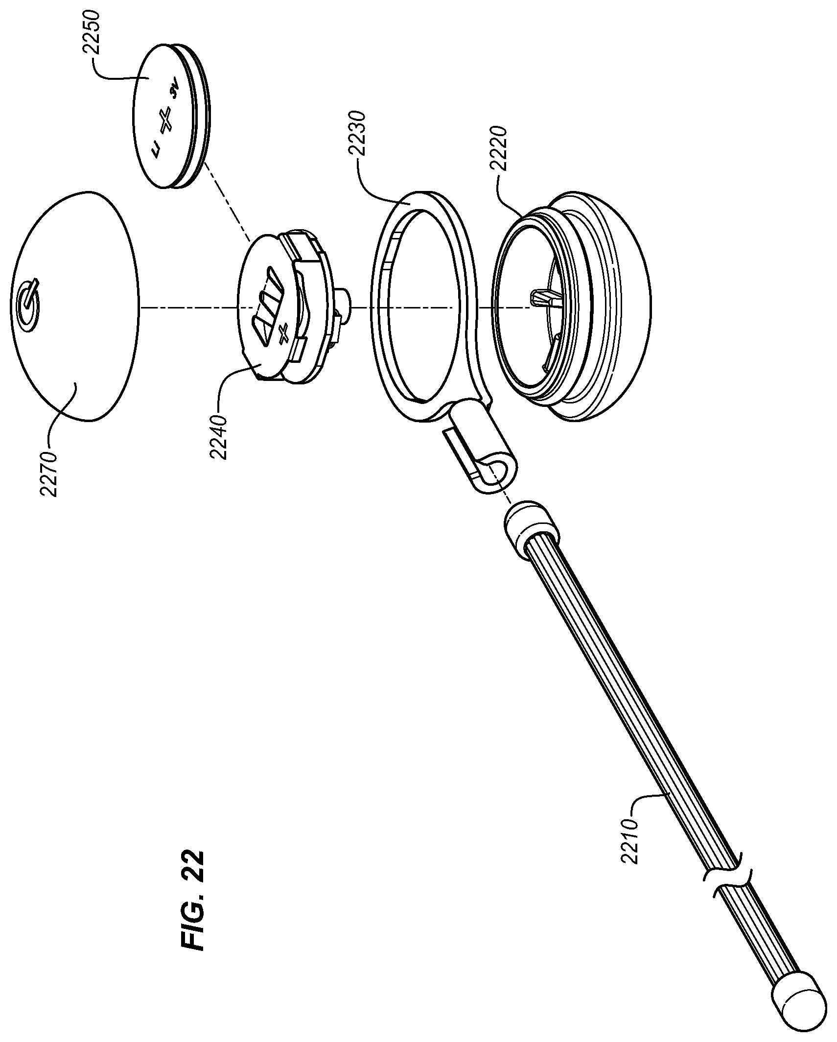
FIG. 22 shows an exploded top perspective view of one embodiment of a lighting device; and
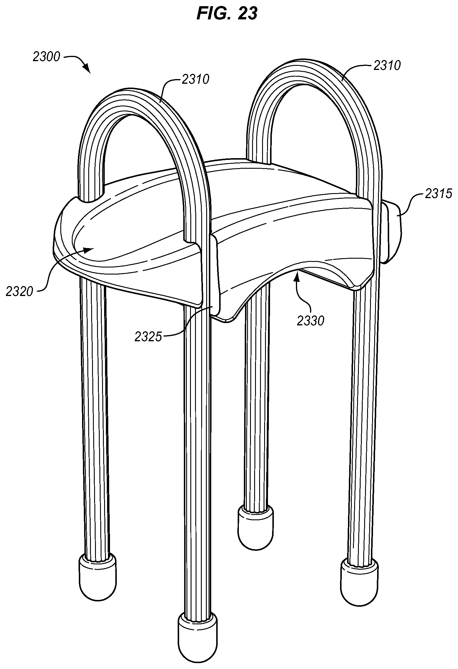
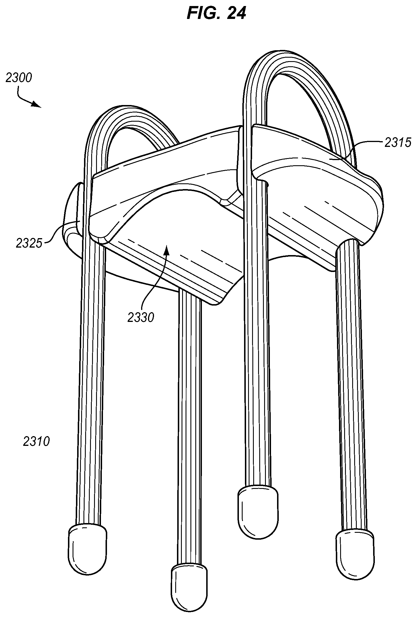
FIGS. 23-26 show an embodiment of an attachment device and the device mounted on handle bars with a flashlight.
DETAILED DESCRIPTION
One embodiment of a twist tie device 10 includes an elongated piece of shape-retaining deformable material, which is typically a metal wire 12. The wire 12 is typically a mild steel wire. The wire 12 will be flexible enough to be bent or tied into a particular shape necessary to accomplish a task but still rigid enough to retain a shape into which it is bent. The diameter of the wire 12 also affects flexibility and shape retention. A diameter of 0.62 inches (smaller size ties use an 18-gauge wire; larger ties use a 16-gauge wire) provides both flexibility and necessary shape retention; however, other diameters may be used depending on the application for which the twist tie device 10 will be used. A cover 14 is bonded to the wire 12 along its entire length. The cover is formed by coextruding the wire 12 through an extrusion head 16 along with a polymer. The wire 12 first is heated to approximately 300.degree. F. to 400.degree. F. and then drawn through the extrusion head 16. As the wire 12 moves through the extrusion head 16, a layer of thermoplastic polymer is deposited evenly around the wire 12 to form a tie layer (cover) 14 between the wire and the outer flexible TPE cover. During this process, the polymer forming the tie layer (cover) 14 adheres to the wire 12 via a chemical in it which bonds to the wire. This forms a bond around the entire perimeter of the wire 12 and along the entire length of the wire 12. The bond prevents the wire 12 from slipping out of the cover 14. The polymer used to make the tie layer (cover) 14 is typically a solid thermoplastic polymer, such as 85 A Duro Exxon Santoprene 8291-85TL or a similar type of polymer. Santoprene is a thermoplastic vulcanizate and is particularly well suited as a cover 14 material because it is formulated to bond to metal; however, any "thermoplastic" resin can be used that has a chemical bonding agent formulated with the resin to bond to metal. Although, the bonding may not function as well, thermoplastic vulcanizate can be used. The durometer of the Santoprene cover 14 is 85 A, which is fairly tough yet flexible. An advantage of using a solid polymer such as Santoprene is that it is resilient.
In one embodiment, the twist tie device includes an internal wire. The wire has a "bonding agent polymer" on it that bonds the wire to the outer layer of TPE (thermoplastic elastomer). Putting an extremely flexible rubber on top of wire 12 without a bond would allow the rubber to slide off. During preparation, the coated wire 12 is heated to accomplish three things: 1. It helps bond the wire to the rubber quicker during the process, which allows for a more consistent part. 2. It prevents the wire from acting as a heat sink as it is pulled through the extrusion die. 3. It lubricates the wire as it goes through the die, helping to prevent surging and sticking inside the die, which makes a better, more consistent part.
Further, an end cap 750 (see FIG. 7) may be injection molded so that there is a polymer bond to the wire cover as part of the formation process. This provides for an integrated end cap 750, improving the life and usefulness of the twist tie 10. The twist tie 10 is placed in a mold to accommodate the molding of the end caps and injection molded.
An outer cover 20 can be coextruded over the cover. This outer cover 20 is typically a different material than the cover 14. The material of the outer cover 20 is typically softer and of a lower durometer. A suitable material for the outer cover 20 is 15 A Duro Teknor Apex Uniprene UN-2005 TPV. Uniprene TPV is a cross-linked elastomeric phase solid thermoplastic polymer. The lower durometer of the outer cover 20 provides a high friction surface. The generally high friction of the outer cover 20 may be increased further by extruding ribs 24 into the outer surface as shown in FIG. 3 to define a texturized gripping surface 25. Although ribs are shown, in alternative embodiments, no ribs may be used or ribs of various shapes may be used, including those that curve, weave, or are oriented in different directions. The gripping surface 25 extends between points 26 and 27 on the left side of the twist tie device 10 as shown in FIG. 3. The gripping surface 25 is well suited to provide a strong grip when the twist tie device 10 is wrapped around itself and provides friction when the device is wrapped around objects. The texturized gripping surface 25 may have other embossed patterns that provide a texturized surface; however, ribs 24 are well suited to the extrusion process by which the twist tie device 10 is made. A non-gripping surface 28 extends between points 26 and 27 on the right side of the twist tie device as shown in FIG. 3. The non-gripping surface 28 is characterized by a smoother texture than the gripping surface 25. Indicia, such as logos or other labels, may be placed on the non-gripping surface 28 and will be easier to read than if placed on the gripping surface 25. In an alternative, a 35a durometer TPE called Monprene from Teknor Apex for the larger gear ties and a 50 shore a Monprene for the smaller gear ties is used. End caps are made of the 50a durometer Monprene. If any polymer that is harder than 35a to 40a durometer for the large gear ties is used, the ties may not bend and grip properly. The material "seats" into itself more effectively when the above durometer materials are used and the ties are twisted to create a strong hold. This is not as impactful with smaller ties due to the fact that they hold lighter loads. The 15a durometer Uniprene may not have the same functional characteristics because it may be too soft for the tie and the material's tensile and tear strength is too low.
The cover 14 and outer cover 20 are bonded tightly so that no water may enter between the wire 12 and either cover 14, 20. However, the ends of the wire 12 are not protected by either cover 14, 20. The ends of the wire may be coated with a protective paint or clear coat to prevent corrosion of the ends of the wire 12, but this is not necessary. In an alternative, end caps are molded on the product.
The twist tie 10 may be used by beginning with the twist tie 10 in a generally straightened position. Articles to be bundled can be gathered into manageable bundles as shown in FIGS. 4-6. The twist tie 10 may be wrapped around each bundle of articles and then twisted to form loops around each bundle. The outer cover 20 will provide a high friction gripping surface that will prevent articles contacting the twist tie 10 from sliding out of the twist tie 10. The soft outer cover 20 will not scratch surfaces of articles within the twist tie 10. The twist tie 10 can be left in its twisted position around bundled articles for as long as necessary. The resilient cover 14 and outer cover 20 will resist taking a permanent set due to being compressed due to twisting the twist tie 10 together, or compression due to pressure exerted on the articles within the twist tie 10. Due to the durable construction of the twist tie 10, it may be used effectively in temperatures from -50.degree. F. to 200.degree. F. Additionally, the covers 14, 20 will prevent the twist tie 10 from breaking if the wire 12 were to break because the bond between the cover 14 and the wire 12 will prevent the wire 12 from exiting the covers 14, 20. The integration of the bonded inner and outer cover to the wire core, the outer textured surface, and the end caps provide for an extremely useful tie. Due to the bonding of the inner and outer cover to the wire core, the tie acts as a single piece of material. Therefore, when bending and twisting the tie, a firm hold is established and the slippage of the material of the tie between itself is reduced. The outer textured surface adds to the gripping function as well. The end caps provide for enhanced hold and gripping as well, as they can be inserted into various channels or holes. The ridge that is at approximately a right angle between the main body of the cord and the end cap can be used to catch against surfaces, providing an enhanced grip or hold.
FIG. 7 shows an embodiment of a lighting device with integrated twist ties 10. Lighting device 700 includes body 705, cap 710, lighting mechanism 715, and battery 720. Body 705 has two grooves 725 each for receiving a twist tie 10. Grooves 725 have a diameter that is approximately equal to the cross-sectional diameter of twist ties 10. The opening of the grooves is less than the diameter of the twist ties 10. Twist ties 10 may be inserted into grooves 725 (as shown) through a combination of compressing the rubberized coating and the body 705. In many embodiments, body 705 is some form of plastic. Optionally, some or all of body 705 may be translucent. Optionally, some or all of body 705 may be transparent. Optionally, some or all of cap 710 may be translucent. Optionally, some or all of cap 710 may be transparent. Various embodiments integrating the twist ties may be referred to as holders, receivers, attachment and attachment mechanisms, receiving attachments, etc.
FIG. 8A shows a cross-section of the body 705. In this example, the to-scale drawing shows the relative width of the groove 725 to the opening 810. Also visible is lip 815 for the snap fit attachment of cap 710. The positioning of electronics housing 820 also is shown. FIG. 8B shows a top view and some of the same features. The dimensions of these to-scale drawings are only exemplary, and various widths and shapes may be employed. The ratio of the groove to the opening only needs to be sufficient to prevent the twist tie 10 from releasing under normal use. Another feature of the twist tie 10 is the end caps 750 that are extruded as part of the formation process such that the tie body 755 and the end caps 750 are one piece of material. This ensures sound attachment. These end caps 750 prevent the twist tie 10 from slipping out in the longitudinal direction.
FIG. 9 shows a view of the back of body 705. Body 705 has a curved surface 910 with a lip 915 on either end. The curved surface 910 is shaped to conform to a tube-like structure. This is shown in FIG. 10 with lighting device 700 situated on a tube 1000. This configuration is designed to fit on the tubes forming the structure of a bike, scooter, or other vehicle or object having tube-like supports. After placing the lighting device on the tube 1000, the twist ties 10 are wrapped around the tube 1000 forming a secure attachment.
FIG. 11 shows an embodiment of twist tie 10 integrated with a lighting device 1100. Lighting device 1100 generally includes a housing 1110 and a light 1120. Housing 1110 houses the electronics and power source of the light. Housing 1110 includes an aperture 1130 approximately the size and shape of a cross section of the twist tie 10 (although various sized apertures are appropriate). Twist tie 10 is passed through aperture 1130 and then coiled around itself forming coil 1140. This provides a secure connection. The loose end of twist tie 10 then may be arranged as shown to offer support to lighting device 1100. Lighting device 1100 is sufficiently light in weight, such that the rigidity of twist tie 10 may support it. The loose end of twist tie 10 may be tied around various objects and used to pose lighting device 1100 in a position convenient to the user. The frictional surface of twist tie 10 provides high friction and good hold around a variety of objects. The lighting device shown is the Inova.RTM. Microlight.TM.; however, many different lighting devices may be substituted.
FIG. 12 shows receiving attachment 1300 for integrating with an object bearing a clip or other protrusion. The clip portion of a device or case may be sized to integrate into clip aperture 1310 oriented in body 1305. In some embodiments, the clip portion may include a tab at the bottom 1307 for locking a clip into clip aperture 1310. Cylindrical holders 1355, 1356 include an aperture that is less than the width of twist tie 10 such that the cylindrical holders 1355 flex and bend as does the twist tie 10 to receive twist tie 10 and hold it firmly in place. Cylindrical holders 1355, 1356 open in different directions in order to provide for ease of use and flexibility. This configuration may be advantageous in that the receiving attachment 1300 may be mounted in a car vent or other area using the configuration shown in FIG. 12. As shown in FIG. 13, by bending twist tie 10 away from bottom cylindrical holders 1356, an upright stand is formed. In the above embodiments including a twist tie, both ends of the twist tie may be bent around a bar (such as the handle bars of a bike or other object), as above with lighting device 1100. The cylindrical holders may be oriented in a variety of positions, and a variety of number of holders may be utilized. Various other receiving mechanisms may be substituted for clip aperture 1310. Cylindrical holders 1355, 1356, body 1305, and twist tie 10 may be formed to fit with a variety of objects by forming connection mechanisms on any side of the body. Cylindrical holders 1355, 1356 and body 1305 may be formed as part of the housing of various objects such as cases, flashlights, electronic devices, and virtually any object having a plastic housing. Twist tie 10 then may be fitted into cylindrical holders 1355, 1356, enabling attachment to almost any object that the twist tie 10 may fit around or into. The cylindrical holders 1355, 1356 are not limited to those shown in FIGS. 10, 13, and 14; and various holders for twist tie 10 may be implemented in a variety of positions and configurations.
FIG. 14 shows yet another embodiment of an apparatus incorporating a twist tie 10. This embodiment includes a microlight, an S-Biner.RTM., and a first and second twist tie 10. The device includes LED 1410 (which in alternatives can be a different light-providing mechanism), upper body 1405, actuator 1415, lower body portion 1425, and S-Biner.RTM. 1420. FIG. 15 is a view from the bottom of the lighting apparatus. The lower body portion 1425 that includes tie seats 1430 and 1440 is shown. FIG. 16 shows the lower body portion 1425 with the other portions removed. Clearly visible are the tie seats 1430 and 1440 which are shaped and sized to hold twist ties 10. The front upper body 1405 slides into front lower body portion 1145, and then a rear portion snaps into place by deflecting front snap fit tab 1450 and rear snap fit tab 1455. In this way, the upper body containing a lighting mechanism can be mounted on one of twist ties 10 placed into tie seats 1430 and 1440. Caps 710 prevent twist ties 10 from sliding out. Twist ties 10 may be bent to stand the apparatus upright or attach it to various objects, as well as using S-Biner.RTM. 1420 to hook the device to various objects. S-Biner.RTM. 1420 is a device having a carabineer gate on either side, although a regular carabineer or other hooking device may be substituted in alternatives. Various other body forms may be made to hold twist ties 10, those body forms including one or more seats or grooves to hold twist ties 10.
FIG. 17 shows a top perspective view of one embodiment of a lighting device 1700. This lighting device provides for a microlight 1740 to be removable attached to a twist tie 1710 similar to as in FIG. 14. Lighting device 1700 includes a first attachment piece 1720 and a second attachment piece 1730.
FIG. 18A shows a side view of one-half of a connection device of the lighting device of FIG. 17, and FIG. 18B shows a front view of one-half of the connection device of the lighting device of FIG. 17. Second attachment piece 1730 is typically made of molded plastic; however, other materials such as metal may be used. Second attachment piece 1730 includes an open end 1820 for receiving microlight 1740. Slot 1810 is sized to match the radius of twist tie 1710 which has a capped end that approximately fits in slot 1815. When first attachment piece 1720 and second attachment piece 1730 are integrated, the end cap of twist tie 1710 is held in place by narrower slot 1810. Snap insert receiver 1825 provides for the snap fit of microlight 1740.
FIG. 19 shows a cross section of one-half of the connection device of the lighting device of FIG. 17. Here, the opening 1920 for receiving the other half of the connection device is clear. The slot 1815 is shown, defined by ridge 1910 and slot 1810.
FIG. 20A shows a side view of the other half 1720 of a connection device of the lighting device of FIG. 17. First attachment 1720 includes a snap fit tab 2015 having a lip that fits into snap insert receiver 1825, which is a slot having a receiver for the tab and the lip such that the tab bends and snaps into place with the lip holding it there. The outer connection portion 2020 provides for a mated fit into the open end 1820. End 2010 is sized to mate with and fit over slot 1810. FIG. 20B shows a front view of the other half of the connection device of the lighting device of FIG. 17. FIG. 21 shows a cross section of the other half of the connection device of the lighting device of FIG. 17. Here the lip on the snap fit tab 2015 is clearly visible.
FIG. 22 shows an exploded top perspective view of one embodiment of a lighting device. This lighting device includes a twist tie 2210 as described herein. A connector 2230 having a narrowed end attachment for receiving twist tie 2210 provides for attachment into a lighting mechanism which includes top and bottom cover 2270, 2220, a lighting mechanism, and battery which all fit together. The lighting mechanism described in U.S. Pat. No. 7,683,275 may be used in this configuration and is incorporated by reference herein.
FIGS. 23-26 show an embodiment of a connection device. In this case the connection device 2300 is configured to accept objects with a circular cross section in the top receiver 2320 and the bottom receiver 2330. Although connection device 2300 is adapted to accept such objects, it may be used with items not including a circular cross-section. In one configuration, connection device 2300 is configured to connect to a bicycle hand bars 2520 at receiver 2330 and a flashlight 2510 at receiver 2320, as shown in FIGS. 25-26. FIG. 25 shows the connection device 2300 being placed on the handle bars 2520 for mounting. FIG. 26 shows the ties 2310 being twisted 2610 in order to mount the connection device 2300. The connection device 2300 has significant advantages when combine with the ties described herein, since it can be placed and removed quickly, but still holds its position well in use. As shown, the receivers 2320 and 2330 in body 2315 are curved to fit typically shaped handle bars and flashlights respectively. The body 2315 further includes tie grooves 2325. These grooves are generally shaped and sized such that the ties 2310 may be replaced and removed when pulled through the side openings in the grooves 2325. The grooves 2325 generally hold the ties 2310 unless significant force is applied however. In alternatives, other grooves or simply holes may be used; however, it may be advantageous to be able to replace ties 2310 over a long time period since they may wear. The friction provided by ties 2310, under tension, generally provides for interface resistant to movement under normal riding conditions. This is a result of the material of the ties 2310 including their ridges.
While specific embodiments have been described in detail in the foregoing detailed description and illustrated in the accompanying drawings, it will be appreciated by those skilled in the art that various modifications and alternatives to those details could be developed in light of the overall teachings of the disclosure and the broad inventive concepts thereof. It is understood, therefore, that the scope of this disclosure is not limited to the particular examples and implementations disclosed herein, but is intended to cover modifications within the spirit and scope thereof as defined by the appended claims and any and all equivalents thereof. Note that, although particular embodiments are shown, features of each attachment may be interchanged between embodiments.
* * * * *
References
D00000
D00001
D00002
D00003
D00004
D00005
D00006
D00007
D00008
D00009
D00010
D00011
D00012
D00013
D00014
D00015
D00016

D00017

D00018
D00019
D00020
D00021

D00022

XML
uspto.report is an independent third-party trademark research tool that is not affiliated, endorsed, or sponsored by the United States Patent and Trademark Office (USPTO) or any other governmental organization. The information provided by uspto.report is based on publicly available data at the time of writing and is intended for informational purposes only.
While we strive to provide accurate and up-to-date information, we do not guarantee the accuracy, completeness, reliability, or suitability of the information displayed on this site. The use of this site is at your own risk. Any reliance you place on such information is therefore strictly at your own risk.
All official trademark data, including owner information, should be verified by visiting the official USPTO website at www.uspto.gov. This site is not intended to replace professional legal advice and should not be used as a substitute for consulting with a legal professional who is knowledgeable about trademark law.