Apportionment of forces for multi-touch input devices of electronic devices
Bijamov , et al. Ja
U.S. patent number 10,545,604 [Application Number 15/306,034] was granted by the patent office on 2020-01-28 for apportionment of forces for multi-touch input devices of electronic devices. This patent grant is currently assigned to Apple Inc.. The grantee listed for this patent is Apple Inc.. Invention is credited to Alex Bijamov, Zhiqiang Gu, Wayne C. Westerman.


View All Diagrams
| United States Patent | 10,545,604 |
| Bijamov , et al. | January 28, 2020 |
Apportionment of forces for multi-touch input devices of electronic devices
Abstract
Systems and methods are disclosed herein for determining the amounts of force applied by at least two fingers of a user to a touch input device having a touch input surface. In one example, a system may include a plurality of force sensors distributed about the touch input surface; a plurality of touch sensors distributed about the touch input surface; and a module for apportioning a first amount of force as measured by the plurality of force sensors to one of the at least two fingers, and for apportioning a second amount of force as measured by the plurality of force sensors to another of the at least two fingers. The system may also include a persistent data structure including force calibration data with force deflection measurement values as measured by each of the plurality of force sensors in response to a standardized force applied to various known locations on the touch input surface. The system may also include one or more matched filter modules.
| Inventors: | Bijamov; Alex (Cupertino, CA), Westerman; Wayne C. (Cupertino, CA), Gu; Zhiqiang (Mountain View, CA) | ||||||||||
|---|---|---|---|---|---|---|---|---|---|---|---|
| Applicant: |
|
||||||||||
| Assignee: | Apple Inc. (Cupertino,
CA) |
||||||||||
| Family ID: | 50771644 | ||||||||||
| Appl. No.: | 15/306,034 | ||||||||||
| Filed: | April 21, 2014 | ||||||||||
| PCT Filed: | April 21, 2014 | ||||||||||
| PCT No.: | PCT/US2014/034791 | ||||||||||
| 371(c)(1),(2),(4) Date: | October 21, 2016 | ||||||||||
| PCT Pub. No.: | WO2015/163842 | ||||||||||
| PCT Pub. Date: | October 29, 2015 |
Prior Publication Data
| Document Identifier | Publication Date | |
|---|---|---|
| US 20170038905 A1 | Feb 9, 2017 | |
| Current U.S. Class: | 1/1 |
| Current CPC Class: | G06F 3/0414 (20130101); G06F 3/0416 (20130101); G06F 2203/04106 (20130101); G06F 2203/04102 (20130101); G06F 2203/04105 (20130101); G06F 2203/04104 (20130101) |
| Current International Class: | G06F 3/041 (20060101) |
References Cited [Referenced By]
U.S. Patent Documents
| 3001049 | September 1961 | Didier |
| 3390287 | June 1968 | Sonderegger |
| 3419739 | December 1968 | Clements |
| 4236132 | November 1980 | Zissimopoulos |
| 4412148 | October 1983 | Klicker et al. |
| 4414984 | November 1983 | Zarudiansky |
| 4490815 | December 1984 | Umehara et al. |
| 4695813 | September 1987 | Nobutoki et al. |
| 4975616 | December 1990 | Park |
| 5010772 | April 1991 | Bourland |
| 5245734 | September 1993 | Issartel |
| 5283408 | February 1994 | Chen |
| 5293161 | March 1994 | MacDonald et al. |
| 5317221 | May 1994 | Kubo et al. |
| 5365140 | November 1994 | Ohya et al. |
| 5434549 | July 1995 | Hirabayashi et al. |
| 5436622 | July 1995 | Gutman et al. |
| 5510584 | April 1996 | Norris |
| 5510783 | April 1996 | Findlater et al. |
| 5513100 | April 1996 | Parker et al. |
| 5587875 | December 1996 | Sellers |
| 5590020 | December 1996 | Sellers |
| 5602715 | February 1997 | Lempicki et al. |
| 5619005 | April 1997 | Shibukawa et al. |
| 5621610 | April 1997 | Moore et al. |
| 5625532 | April 1997 | Sellers |
| 5629578 | May 1997 | Winzer et al. |
| 5635928 | June 1997 | Takagi et al. |
| 5718418 | February 1998 | Gugsch |
| 5739759 | April 1998 | Nakazawa et al. |
| 5742242 | April 1998 | Sellers |
| 5783765 | July 1998 | Muramatsu |
| 5793605 | August 1998 | Sellers |
| 5812116 | September 1998 | Malhi |
| 5813142 | September 1998 | Demon |
| 5818149 | October 1998 | Safari et al. |
| 5896076 | April 1999 | Van Namen |
| 5907199 | May 1999 | Miller |
| 5951908 | September 1999 | Cui et al. |
| 5959613 | September 1999 | Rosenberg et al. |
| 5973441 | October 1999 | Lo et al. |
| 5982304 | November 1999 | Selker et al. |
| 5982612 | November 1999 | Roylance |
| 5995026 | November 1999 | Sellers |
| 5999084 | December 1999 | Armstrong |
| 6069433 | May 2000 | Lazarus et al. |
| 6078308 | June 2000 | Rosenberg et al. |
| 6104947 | August 2000 | Heikkila et al. |
| 6127756 | October 2000 | Iwaki |
| 6135886 | October 2000 | Armstrong |
| 6198206 | March 2001 | Saarmaa |
| 6218966 | April 2001 | Goodwin |
| 6219033 | April 2001 | Rosenberg |
| 6220550 | April 2001 | McKillip, Jr. |
| 6222525 | April 2001 | Armstrong |
| 6252336 | June 2001 | Hall |
| 6342880 | January 2002 | Rosenberg et al. |
| 6351205 | February 2002 | Armstrong |
| 6373465 | April 2002 | Jolly et al. |
| 6408187 | June 2002 | Merriam |
| 6411276 | June 2002 | Braun et al. |
| 6429849 | August 2002 | An |
| 6437485 | August 2002 | Johansson |
| 6438393 | August 2002 | Surronen |
| 6444928 | September 2002 | Okamoto et al. |
| 6455973 | September 2002 | Ineson |
| 6465921 | October 2002 | Horng |
| 6552404 | April 2003 | Hynes |
| 6552471 | April 2003 | Chandran et al. |
| 6557072 | April 2003 | Osborn |
| 6642857 | November 2003 | Schediwy |
| 6693626 | February 2004 | Rosenberg |
| 6717573 | April 2004 | Shahoian et al. |
| 6747400 | June 2004 | Maichl et al. |
| 6809462 | October 2004 | Pelrine et al. |
| 6809727 | October 2004 | Piot et al. |
| 6864877 | March 2005 | Braun et al. |
| 6906697 | June 2005 | Rosenberg |
| 6906700 | June 2005 | Armstrong |
| 6906703 | June 2005 | Vablais et al. |
| 6952203 | October 2005 | Banerjee et al. |
| 6954657 | October 2005 | Bork et al. |
| 6963762 | November 2005 | Kaaresoja et al. |
| 6965189 | November 2005 | Menzel |
| 6995752 | February 2006 | Lu |
| 7005811 | February 2006 | Wakuda et al. |
| 7016707 | March 2006 | Fujisawa et al. |
| 7022927 | April 2006 | Hsu |
| 7023112 | April 2006 | Miyamoto et al. |
| 7081701 | July 2006 | Yoon et al. |
| 7091948 | August 2006 | Chang et al. |
| 7121147 | October 2006 | Okada |
| 7123948 | October 2006 | Nielsen |
| 7130664 | October 2006 | Williams |
| 7136045 | November 2006 | Rosenberg et al. |
| 7161580 | January 2007 | Bailey et al. |
| 7162928 | January 2007 | Shank et al. |
| 7170498 | January 2007 | Huang |
| 7176906 | February 2007 | Williams et al. |
| 7180500 | February 2007 | Marvit et al. |
| 7182691 | February 2007 | Schena |
| 7194645 | March 2007 | Bieswanger et al. |
| 7205978 | April 2007 | Poupyrev |
| 7217891 | May 2007 | Fischer et al. |
| 7218310 | May 2007 | Tierling et al. |
| 7219561 | May 2007 | Okada |
| 7253350 | August 2007 | Noro et al. |
| 7269484 | September 2007 | Hein |
| 7333604 | February 2008 | Zernovizky et al. |
| 7334350 | February 2008 | Ellis |
| 7348968 | March 2008 | Dawson |
| 7382357 | June 2008 | Panotopoulos et al. |
| 7388741 | June 2008 | Konuma et al. |
| 7392066 | June 2008 | Hapamas |
| 7423631 | September 2008 | Shahoian et al. |
| 7446752 | November 2008 | Goldenberg et al. |
| 7469155 | December 2008 | Chu |
| 7469595 | December 2008 | Kessler et al. |
| 7471033 | December 2008 | Thiesen et al. |
| 7495358 | February 2009 | Kobayashi et al. |
| 7508382 | March 2009 | Denoue et al. |
| 7561142 | July 2009 | Shahoian et al. |
| 7562468 | July 2009 | Ellis |
| 7569086 | August 2009 | Chandran |
| 7575368 | August 2009 | Guillaume |
| 7586220 | September 2009 | Roberts |
| 7619498 | November 2009 | Miura |
| 7639232 | December 2009 | Grant et al. |
| 7641618 | January 2010 | Noda et al. |
| 7647196 | January 2010 | Kahn et al. |
| 7649305 | January 2010 | Priya et al. |
| 7675253 | March 2010 | Dorel |
| 7675414 | March 2010 | Ray |
| 7679611 | March 2010 | Schena |
| 7707742 | May 2010 | Ellis |
| 7710399 | May 2010 | Bruneau et al. |
| 7732951 | June 2010 | Mukaide |
| 7737828 | June 2010 | Yang et al. |
| 7742036 | June 2010 | Grant et al. |
| 7788032 | August 2010 | Moloney |
| 7793429 | September 2010 | Ellis |
| 7793430 | September 2010 | Ellis |
| 7798982 | September 2010 | Zets et al. |
| 7868489 | January 2011 | Amemiya et al. |
| 7886621 | February 2011 | Smith et al. |
| 7888892 | February 2011 | McReynolds et al. |
| 7893922 | February 2011 | Klinghult et al. |
| 7919945 | April 2011 | Houston et al. |
| 7929382 | April 2011 | Yamazaki |
| 7946483 | May 2011 | Miller et al. |
| 7952261 | May 2011 | Lipton et al. |
| 7952566 | May 2011 | Poupyrev et al. |
| 7956770 | June 2011 | Klinghult et al. |
| 7961909 | June 2011 | Mandella et al. |
| 8018105 | September 2011 | Erixon et al. |
| 8031172 | October 2011 | Kruse et al. |
| 8044940 | October 2011 | Narusawa |
| 8069881 | December 2011 | Cunha |
| 8072418 | December 2011 | Crawford et al. |
| 8077145 | December 2011 | Rosenberg et al. |
| 8081156 | December 2011 | Ruettiger |
| 8082640 | December 2011 | Takeda |
| 8084968 | December 2011 | Murray et al. |
| 8098234 | January 2012 | Lacroix et al. |
| 8123660 | February 2012 | Kruse et al. |
| 8125453 | February 2012 | Shahoian et al. |
| 8141276 | March 2012 | Ellis |
| 8156809 | April 2012 | Tierling et al. |
| 8169401 | May 2012 | Hardwick |
| 8174344 | May 2012 | Yakima et al. |
| 8174372 | May 2012 | da Costa |
| 8179027 | May 2012 | Barta et al. |
| 8179202 | May 2012 | Cruz-Hernandez et al. |
| 8188623 | May 2012 | Park |
| 8205356 | June 2012 | Ellis |
| 8210942 | July 2012 | Shimabukuro et al. |
| 8232494 | July 2012 | Purcocks |
| 8242641 | August 2012 | Bae |
| 8248277 | August 2012 | Peterson et al. |
| 8248278 | August 2012 | Schlosser et al. |
| 8253686 | August 2012 | Kyung et al. |
| 8255004 | August 2012 | Huang et al. |
| 8261468 | September 2012 | Ellis |
| 8264465 | September 2012 | Grant et al. |
| 8270114 | September 2012 | Argumedo et al. |
| 8288899 | October 2012 | Park et al. |
| 8291614 | October 2012 | Ellis |
| 8294600 | October 2012 | Peterson et al. |
| 8315746 | November 2012 | Cox et al. |
| 8339250 | December 2012 | Je et al. |
| 8344834 | January 2013 | Niiyama |
| 8345013 | January 2013 | Heubel et al. |
| 8373549 | February 2013 | Fadell et al. |
| 8378797 | February 2013 | Pance et al. |
| 8378798 | February 2013 | Bells et al. |
| 8378965 | February 2013 | Gregorio et al. |
| 8384316 | February 2013 | Houston et al. |
| 8384679 | February 2013 | Paleczny et al. |
| 8390594 | March 2013 | Modarres et al. |
| 8395587 | March 2013 | Cauwels et al. |
| 8398570 | March 2013 | Mortimer et al. |
| 8411058 | April 2013 | Wong et al. |
| 8446264 | May 2013 | Tanase |
| 8451255 | May 2013 | Weber et al. |
| 8452345 | May 2013 | Lee et al. |
| 8461951 | June 2013 | Gassmann et al. |
| 8466889 | June 2013 | Tong et al. |
| 8471690 | June 2013 | Hennig et al. |
| 8487759 | July 2013 | Hill |
| 8515398 | August 2013 | Song et al. |
| 8542134 | September 2013 | Peterson et al. |
| 8545322 | October 2013 | George et al. |
| 8547341 | October 2013 | Takashima et al. |
| 8547350 | October 2013 | Anglin |
| 8552859 | October 2013 | Pakula et al. |
| 8570291 | October 2013 | Motomura |
| 8575794 | November 2013 | Lee et al. |
| 8587955 | November 2013 | DiFonzo et al. |
| 8593409 | November 2013 | Heubel |
| 8596755 | December 2013 | Hibi |
| 8598893 | December 2013 | Camus |
| 8599047 | December 2013 | Schlosser et al. |
| 8599152 | December 2013 | Wurtenberger et al. |
| 8600354 | December 2013 | Esaki |
| 8614431 | December 2013 | Huppi et al. |
| 8621348 | December 2013 | Ramsay et al. |
| 8629843 | January 2014 | Steeves et al. |
| 8633916 | January 2014 | Bernstein et al. |
| 8674941 | March 2014 | Casparian et al. |
| 8680723 | March 2014 | Subramanian |
| 8681092 | March 2014 | Harada et al. |
| 8682396 | March 2014 | Yang et al. |
| 8686952 | April 2014 | Pope et al. |
| 8710966 | April 2014 | Hill |
| 8723813 | May 2014 | Park et al. |
| 8735755 | May 2014 | Peterson et al. |
| 8760273 | June 2014 | Casparian et al. |
| 8780060 | July 2014 | Maschmeyer et al. |
| 8787006 | July 2014 | Golko et al. |
| 8797152 | August 2014 | Henderson et al. |
| 8798534 | August 2014 | Rodriguez et al. |
| 8803842 | August 2014 | Wakasugi et al. |
| 8816981 | August 2014 | Kai et al. |
| 8836502 | September 2014 | Culbert et al. |
| 8845071 | September 2014 | Yamamoto et al. |
| 8857248 | October 2014 | Shih et al. |
| 8860562 | October 2014 | Hill |
| 8861776 | October 2014 | Lastrucci |
| 8866600 | October 2014 | Yang et al. |
| 8890666 | November 2014 | Parker et al. |
| 8890668 | November 2014 | Pance et al. |
| 8918215 | December 2014 | Bosscher et al. |
| 8928621 | January 2015 | Ciesla et al. |
| 8947383 | February 2015 | Ciesla et al. |
| 8948821 | February 2015 | Newham et al. |
| 8952937 | February 2015 | Shih et al. |
| 8970534 | March 2015 | Adachi et al. |
| 8976141 | March 2015 | Myers et al. |
| 9008730 | April 2015 | Kim et al. |
| 9012795 | April 2015 | Niu |
| 9013426 | April 2015 | Cole et al. |
| 9019088 | April 2015 | Zawacki et al. |
| 9024738 | May 2015 | Van Schyndel et al. |
| 9035887 | May 2015 | Prud'Hommeaux et al. |
| 9072576 | July 2015 | Nishiura |
| 9083821 | July 2015 | Hughes |
| 9098984 | August 2015 | Heubel et al. |
| 9098991 | August 2015 | Park et al. |
| 9117347 | August 2015 | Matthews |
| 9122325 | September 2015 | Peshkin et al. |
| 9131039 | September 2015 | Behles |
| 9134834 | September 2015 | Reshef |
| 9158379 | October 2015 | Cruz-Hernandez et al. |
| 9178509 | November 2015 | Bernstein |
| 9189932 | November 2015 | Kerdemelidis et al. |
| 9201458 | December 2015 | Hunt et al. |
| 9202355 | December 2015 | Hill |
| 9219401 | December 2015 | Kim et al. |
| 9235267 | January 2016 | Pope et al. |
| 9274601 | March 2016 | Faubert et al. |
| 9274602 | March 2016 | Garg et al. |
| 9274603 | March 2016 | Modarres et al. |
| 9275815 | March 2016 | Hoffmann |
| 9293054 | March 2016 | Bruni et al. |
| 9300181 | March 2016 | Maeda et al. |
| 9310906 | April 2016 | Yumiki et al. |
| 9317116 | April 2016 | Ullrich et al. |
| 9317118 | April 2016 | Puskarich |
| 9317154 | April 2016 | Perlin et al. |
| 9318942 | April 2016 | Sugita et al. |
| 9325230 | April 2016 | Yamada et al. |
| 9330544 | May 2016 | Levesque et al. |
| 9357052 | May 2016 | Ullrich |
| 9360944 | June 2016 | Pinault |
| 9380145 | June 2016 | Tartz et al. |
| 9390599 | July 2016 | Weinberg |
| 9396434 | July 2016 | Rothkopf |
| 9405369 | August 2016 | Modarres et al. |
| 9411423 | August 2016 | Heubel |
| 9417695 | August 2016 | Griffin et al. |
| 9430042 | August 2016 | Levin |
| 9448628 | September 2016 | Tan et al. |
| 9448713 | September 2016 | Cruz-Hernandez et al. |
| 9449476 | September 2016 | Lynn |
| 9454239 | September 2016 | Elias et al. |
| 9467033 | October 2016 | Jun et al. |
| 9468846 | October 2016 | Terrell et al. |
| 9471172 | October 2016 | Sirois |
| 9480947 | November 2016 | Jiang et al. |
| 9501912 | November 2016 | Hayskjold et al. |
| 9544694 | January 2017 | Abe et al. |
| 9576445 | February 2017 | Cruz-Hernandez |
| 9595659 | March 2017 | Kim |
| 9600070 | March 2017 | Chatterjee et al. |
| 9622214 | April 2017 | Ryu |
| 9659482 | May 2017 | Yang et al. |
| 9594450 | July 2017 | Lynn et al. |
| 9727157 | August 2017 | Ham et al. |
| 9778743 | October 2017 | Grant et al. |
| 9779592 | October 2017 | Hoen |
| 9823833 | November 2017 | Grant et al. |
| 9934661 | April 2018 | Hill |
| 9990099 | June 2018 | Ham et al. |
| 10061386 | August 2018 | Frescas et al. |
| 10062832 | August 2018 | Caraveo et al. |
| 10067585 | September 2018 | Kim |
| 10139907 | November 2018 | Billington |
| 10204494 | February 2019 | Do et al. |
| 10338682 | July 2019 | Heubel et al. |
| 10345905 | July 2019 | McClure et al. |
| 10367950 | July 2019 | Davis et al. |
| 2002/0194284 | December 2002 | Haynes |
| 2003/0210259 | November 2003 | Liu |
| 2003/0214485 | November 2003 | Roberts |
| 2004/0021663 | February 2004 | Suzuki et al. |
| 2004/0127198 | July 2004 | Roskind et al. |
| 2005/0057528 | March 2005 | Kleen |
| 2005/0107129 | May 2005 | Kaewell et al. |
| 2005/0110778 | May 2005 | Ben Ayed |
| 2005/0118922 | June 2005 | Endo |
| 2005/0217142 | October 2005 | Ellis |
| 2005/0237306 | October 2005 | Klein et al. |
| 2005/0248549 | November 2005 | Dietz et al. |
| 2005/0258715 | November 2005 | Schlabach |
| 2006/0014569 | January 2006 | DelGiorno |
| 2006/0154674 | July 2006 | Landschaft et al. |
| 2006/0209037 | September 2006 | Wang et al. |
| 2006/0239746 | October 2006 | Grant |
| 2006/0252463 | November 2006 | Liao |
| 2007/0032270 | February 2007 | Orr |
| 2007/0043725 | February 2007 | Hotelling et al. |
| 2007/0099574 | May 2007 | Wang |
| 2007/0152974 | July 2007 | Kim et al. |
| 2007/0168430 | July 2007 | Brun et al. |
| 2007/0178942 | August 2007 | Sadler et al. |
| 2007/0188450 | August 2007 | Hernandez et al. |
| 2008/0084384 | April 2008 | Gregorio et al. |
| 2008/0165148 | July 2008 | Williamson |
| 2008/0181501 | July 2008 | Faraboschi |
| 2008/0181706 | July 2008 | Jackson |
| 2008/0192014 | August 2008 | Kent et al. |
| 2008/0204428 | August 2008 | Pierce et al. |
| 2008/0255794 | October 2008 | Levine |
| 2009/0002328 | January 2009 | Ullrich et al. |
| 2009/0015560 | January 2009 | Robinson et al. |
| 2009/0115734 | May 2009 | Fredriksson et al. |
| 2009/0120105 | May 2009 | Ramsay et al. |
| 2009/0128503 | May 2009 | Grant et al. |
| 2009/0135142 | May 2009 | Fu et al. |
| 2009/0167702 | July 2009 | Nurmi |
| 2009/0167704 | July 2009 | Terlizzi et al. |
| 2009/0218148 | September 2009 | Hugeback et al. |
| 2009/0225046 | September 2009 | Kim et al. |
| 2009/0236210 | September 2009 | Clark et al. |
| 2009/0267892 | October 2009 | Faubert |
| 2009/0291670 | November 2009 | Sennett et al. |
| 2009/0313542 | December 2009 | Cruz-Hernandez et al. |
| 2010/0020036 | January 2010 | Hui et al. |
| 2010/0053087 | March 2010 | Dai et al. |
| 2010/0053116 | March 2010 | Daverman et al. |
| 2010/0079264 | April 2010 | Hoellwarth |
| 2010/0089735 | April 2010 | Takeda et al. |
| 2010/0110018 | May 2010 | Faubert et al. |
| 2010/0141408 | June 2010 | Doy et al. |
| 2010/0141606 | June 2010 | Bae et al. |
| 2010/0148944 | June 2010 | Kim et al. |
| 2010/0152620 | June 2010 | Ramsay et al. |
| 2010/0164894 | July 2010 | Kim et al. |
| 2010/0188422 | July 2010 | Shingai et al. |
| 2010/0207906 | August 2010 | Anglin |
| 2010/0231508 | September 2010 | Cruz-Hernandez et al. |
| 2010/0231550 | September 2010 | Cruz-Hernandez et al. |
| 2010/0265197 | October 2010 | Purdy |
| 2010/0309141 | December 2010 | Cruz-Hernandez et al. |
| 2010/0328229 | December 2010 | Weber et al. |
| 2011/0007023 | January 2011 | Abrahamsson |
| 2011/0051334 | March 2011 | Griffith |
| 2011/0053577 | March 2011 | Lee et al. |
| 2011/0084912 | April 2011 | Almalki |
| 2011/0107958 | May 2011 | Pance et al. |
| 2011/0121765 | May 2011 | Anderson et al. |
| 2011/0128239 | June 2011 | Polyakov et al. |
| 2011/0148608 | June 2011 | Grant et al. |
| 2011/0157052 | June 2011 | Lee et al. |
| 2011/0163985 | July 2011 | Bae et al. |
| 2011/0193824 | August 2011 | Modarres et al. |
| 2011/0216013 | September 2011 | Siotis |
| 2011/0248941 | October 2011 | Abdo et al. |
| 2011/0248948 | October 2011 | Griffin et al. |
| 2011/0260988 | October 2011 | Colgate et al. |
| 2011/0263200 | October 2011 | Thornton et al. |
| 2011/0291950 | December 2011 | Tong |
| 2011/0304559 | December 2011 | Pasquero |
| 2012/0068957 | March 2012 | Puskarich et al. |
| 2012/0075198 | March 2012 | Sulem et al. |
| 2012/0086659 | April 2012 | Perlin |
| 2012/0086666 | April 2012 | Badaye |
| 2012/0092263 | April 2012 | Peterson et al. |
| 2012/0126959 | May 2012 | Zarrabi et al. |
| 2012/0127088 | May 2012 | Pance et al. |
| 2012/0133494 | May 2012 | Cruz-Hernandez et al. |
| 2012/0139844 | June 2012 | Ramstein et al. |
| 2012/0206248 | August 2012 | Biggs |
| 2012/0256848 | October 2012 | Madabusi Srinivasan |
| 2012/0274578 | November 2012 | Snow et al. |
| 2012/0280927 | November 2012 | Ludwig |
| 2012/0319987 | December 2012 | Woo |
| 2012/0327006 | December 2012 | Israr et al. |
| 2013/0027345 | January 2013 | Binzel |
| 2013/0033967 | February 2013 | Chuang et al. |
| 2013/0043987 | February 2013 | Kasama et al. |
| 2013/0058816 | March 2013 | Kim |
| 2013/0063356 | March 2013 | Martisauskas |
| 2013/0082970 | April 2013 | Frey |
| 2013/0106699 | May 2013 | Babatunde |
| 2013/0141365 | June 2013 | Lynn et al. |
| 2013/0191741 | July 2013 | Dickinson et al. |
| 2013/0207793 | August 2013 | Weaber et al. |
| 2013/0217491 | August 2013 | Hilbert et al. |
| 2013/0222280 | August 2013 | Sheynblat et al. |
| 2013/0228023 | September 2013 | Drasnin et al. |
| 2013/0261811 | October 2013 | Yagi et al. |
| 2013/0300590 | November 2013 | Dietz et al. |
| 2014/0035397 | February 2014 | Endo et al. |
| 2014/0082490 | March 2014 | Jung et al. |
| 2014/0085065 | March 2014 | Biggs et al. |
| 2014/0143785 | May 2014 | Mistry et al. |
| 2014/0168153 | June 2014 | Deichmann |
| 2014/0168162 | June 2014 | Liao |
| 2014/0197936 | July 2014 | Biggs et al. |
| 2014/0232534 | August 2014 | Birnbaum et al. |
| 2014/0267076 | September 2014 | Birnbaum et al. |
| 2014/0320436 | October 2014 | Modarres |
| 2014/0354585 | December 2014 | Cok |
| 2014/0368260 | December 2014 | Tanada |
| 2015/0005039 | January 2015 | Liu et al. |
| 2015/0040005 | February 2015 | Faaborg |
| 2015/0042610 | February 2015 | Takano |
| 2015/0090572 | April 2015 | Lee et al. |
| 2015/0098309 | April 2015 | Adams et al. |
| 2015/0169059 | June 2015 | Behles et al. |
| 2015/0192414 | July 2015 | Das et al. |
| 2015/0194165 | July 2015 | Faaborg et al. |
| 2015/0205355 | July 2015 | Yairi |
| 2015/0205417 | July 2015 | Yairi et al. |
| 2015/0220199 | August 2015 | Wang et al. |
| 2015/0227204 | August 2015 | Gipson et al. |
| 2015/0296480 | October 2015 | Kinsey et al. |
| 2015/0324049 | November 2015 | Kies et al. |
| 2015/0349619 | December 2015 | Degner et al. |
| 2016/0049265 | February 2016 | Bernstein |
| 2016/0063826 | March 2016 | Morrell et al. |
| 2016/0071384 | March 2016 | Hill |
| 2016/0103544 | April 2016 | Filiz |
| 2016/0103545 | April 2016 | Filiz |
| 2016/0162025 | June 2016 | Shah |
| 2016/0163165 | June 2016 | Morrell et al. |
| 2016/0172953 | June 2016 | Degner et al. |
| 2016/0195929 | July 2016 | Martinez et al. |
| 2016/0196935 | July 2016 | Bernstein |
| 2016/0206921 | July 2016 | Szabados et al. |
| 2016/0211736 | July 2016 | Moussette et al. |
| 2016/0216764 | July 2016 | Morrell et al. |
| 2016/0216766 | July 2016 | Puskarich |
| 2016/0231815 | August 2016 | Moussette et al. |
| 2016/0233012 | August 2016 | Lubinski et al. |
| 2016/0241119 | August 2016 | Keeler |
| 2016/0259480 | September 2016 | Augenbergs et al. |
| 2016/0306423 | October 2016 | Uttermann et al. |
| 2016/0371942 | December 2016 | Smith, IV |
| 2016/0378255 | December 2016 | Butler |
| 2017/0070131 | March 2017 | Degner |
| 2017/0084138 | March 2017 | Hajati et al. |
| 2017/0085163 | March 2017 | Hajati et al. |
| 2017/0090667 | March 2017 | Abdollahian |
| 2017/0153703 | June 2017 | Yun et al. |
| 2017/0192507 | July 2017 | Lee et al. |
| 2017/0192508 | July 2017 | Lim et al. |
| 2017/0242541 | August 2017 | Iuchi |
| 2017/0255295 | September 2017 | Tanemura et al. |
| 2017/0257844 | September 2017 | Miller et al. |
| 2017/0285747 | October 2017 | Chen |
| 2017/0311282 | October 2017 | Miller et al. |
| 2017/0315618 | November 2017 | Ullrich et al. |
| 2017/0345992 | November 2017 | Noguchi |
| 2017/0357325 | December 2017 | Yang et al. |
| 2017/0364158 | December 2017 | Wen et al. |
| 2018/0052550 | February 2018 | Zhang et al. |
| 2018/0060941 | March 2018 | Yang |
| 2018/0075715 | March 2018 | Morrell et al. |
| 2018/0081441 | March 2018 | Pedder et al. |
| 2018/0174409 | June 2018 | Hill |
| 2018/0203513 | July 2018 | Rihn |
| 2018/0302881 | October 2018 | Miller et al. |
| 2019/0027674 | January 2019 | Zhang et al. |
| 2019/0159170 | May 2019 | Miller et al. |
| 2019/0214895 | July 2019 | Moussette et al. |
| 2019/0250713 | August 2019 | Chen |
| 2015100710 | Jul 2015 | AU | |||
| 2016100399 | May 2016 | AU | |||
| 2355434 | Feb 2002 | CA | |||
| 1324030 | Nov 2001 | CN | |||
| 1692371 | Nov 2005 | CN | |||
| 1817321 | Aug 2006 | CN | |||
| 101120290 | Feb 2008 | CN | |||
| 101409164 | Apr 2009 | CN | |||
| 101763192 | Jun 2010 | CN | |||
| 101903848 | Dec 2010 | CN | |||
| 101938207 | Jan 2011 | CN | |||
| 102025257 | Apr 2011 | CN | |||
| 201829004 | May 2011 | CN | |||
| 102163076 | Aug 2011 | CN | |||
| 102246122 | Nov 2011 | CN | |||
| 102315747 | Jan 2012 | CN | |||
| 102591512 | Jul 2012 | CN | |||
| 102667681 | Sep 2012 | CN | |||
| 102713805 | Oct 2012 | CN | |||
| 102768593 | Nov 2012 | CN | |||
| 102844972 | Dec 2012 | CN | |||
| 102915111 | Feb 2013 | CN | |||
| 103019569 | Apr 2013 | CN | |||
| 103154867 | Jun 2013 | CN | |||
| 103181090 | Jun 2013 | CN | |||
| 103218104 | Jul 2013 | CN | |||
| 103278173 | Sep 2013 | CN | |||
| 103416043 | Nov 2013 | CN | |||
| 103440076 | Dec 2013 | CN | |||
| 103567135 | Feb 2014 | CN | |||
| 103970339 | Aug 2014 | CN | |||
| 104220963 | Dec 2014 | CN | |||
| 104956244 | Sep 2015 | CN | |||
| 105556268 | May 2016 | CN | |||
| 19517630 | Nov 1996 | DE | |||
| 10330024 | Jan 2005 | DE | |||
| 102009038103 | Feb 2011 | DE | |||
| 102011115762 | Apr 2013 | DE | |||
| 0483955 | May 1992 | EP | |||
| 1047258 | Oct 2000 | EP | |||
| 1686776 | Aug 2006 | EP | |||
| 2060967 | May 2009 | EP | |||
| 2073099 | Jun 2009 | EP | |||
| 2194444 | Jun 2010 | EP | |||
| 2207080 | Jul 2010 | EP | |||
| 2264562 | Dec 2010 | EP | |||
| 2315186 | Apr 2011 | EP | |||
| 2374430 | Oct 2011 | EP | |||
| 2395414 | Dec 2011 | EP | |||
| 2461228 | Jun 2012 | EP | |||
| 2631746 | Aug 2013 | EP | |||
| 2434555 | Oct 2013 | EP | |||
| H05301342 | Nov 1993 | JP | |||
| 2002199689 | Jul 2002 | JP | |||
| 2002102799 | Sep 2002 | JP | |||
| 200362525 | Mar 2003 | JP | |||
| 2003527046 | Sep 2003 | JP | |||
| 200494389 | Mar 2004 | JP | |||
| 2004236202 | Aug 2004 | JP | |||
| 2006150865 | Jun 2006 | JP | |||
| 3831410 | Oct 2006 | JP | |||
| 2007519099 | Jul 2007 | JP | |||
| 200818928 | Jan 2008 | JP | |||
| 2010536040 | Nov 2010 | JP | |||
| 2010272903 | Dec 2010 | JP | |||
| 2011523840 | Aug 2011 | JP | |||
| 2012135755 | Jul 2012 | JP | |||
| 2013149124 | Aug 2013 | JP | |||
| 2014002729 | Jan 2014 | JP | |||
| 2014509028 | Apr 2014 | JP | |||
| 2014235133 | Dec 2014 | JP | |||
| 2014239323 | Dec 2014 | JP | |||
| 2015153406 | Aug 2015 | JP | |||
| 2015228214 | Dec 2015 | JP | |||
| 2016095552 | May 2016 | JP | |||
| 20050033909 | Apr 2005 | KR | |||
| 1020100046602 | May 2010 | KR | |||
| 1020110101516 | Sep 2011 | KR | |||
| 20130024420 | Mar 2013 | KR | |||
| 200518000 | Nov 2007 | TW | |||
| 200951944 | Dec 2009 | TW | |||
| 201145336 | Dec 2011 | TW | |||
| 201218039 | May 2012 | TW | |||
| 201425180 | Jul 2014 | TW | |||
| WO 97/16932 | May 1997 | WO | |||
| WO 00/051190 | Aug 2000 | WO | |||
| WO 01/059588 | Aug 2001 | WO | |||
| WO 01/089003 | Nov 2001 | WO | |||
| WO 02/073587 | Sep 2002 | WO | |||
| WO 03/038800 | May 2003 | WO | |||
| WO 03/100550 | Dec 2003 | WO | |||
| WO 06/057770 | Jun 2006 | WO | |||
| WO 07/114631 | Oct 2007 | WO | |||
| WO 08/075082 | Jun 2008 | WO | |||
| WO 09/038862 | Mar 2009 | WO | |||
| WO 09/068986 | Jun 2009 | WO | |||
| WO 09/097866 | Aug 2009 | WO | |||
| WO 09/122331 | Oct 2009 | WO | |||
| WO 09/150287 | Dec 2009 | WO | |||
| WO 10/085575 | Jul 2010 | WO | |||
| WO 10/087925 | Aug 2010 | WO | |||
| WO 11/007263 | Jan 2011 | WO | |||
| WO 12/052635 | Apr 2012 | WO | |||
| WO 12/129247 | Sep 2012 | WO | |||
| WO 13/069148 | May 2013 | WO | |||
| WO 13/150667 | Oct 2013 | WO | |||
| WO 13/169302 | Nov 2013 | WO | |||
| WO 13/173838 | Nov 2013 | WO | |||
| WO 13/186846 | Dec 2013 | WO | |||
| WO 13/186847 | Dec 2013 | WO | |||
| WO 14/018086 | Jan 2014 | WO | |||
| WO 14/098077 | Jun 2014 | WO | |||
| WO 13/169299 | Nov 2014 | WO | |||
| WO 15/023670 | Feb 2015 | WO | |||
| WO 16/141482 | Sep 2016 | WO | |||
Other References
|
Astronomer's Toolbox, "The Electromagnetic Spectrum," http://imagine.gsfc.nasa.gov/science/toolbox/emspectrum1.html, updated Mar. 2013, 4 pages. cited by applicant . Hasser et al., "Preliminary Evaluation of a Shape-Memory Alloy Tactile Feedback Display," Advances in Robotics, Mechantronics, and Haptic Interfaces, ASME, DSC-vol. 49, pp. 73-80, 1993. cited by applicant . Hill et al., "Real-time Estimation of Human Impedance for Haptic Interfaces," Stanford Telerobotics Laboratory, Department of Mechanical Engineering, Stanford University, Third Joint Eurohaptics Conference and Symposium on Haptic Interfaces for Virtual Environment and Teleoperator Systems, Salt Lake City, Utah, Mar. 18-20, 2009, pp. 440-445. cited by applicant . Kim et al., "Tactile Rendering of 3D Features on Touch Surfaces," UIST '13, Oct. 8-11, 2013, St. Andrews, United Kingdom, 8 pages. cited by applicant . Lee et al, "Haptic Pen: Tactile Feedback Stylus for Touch Screens," Mitsubishi Electric Research Laboratories, http://wwwlmerl.com, 6 pages, Oct. 2004. cited by applicant . Actuator definition downloaded from http://www.thefreedictionary.com/actuator on May 3, 2018, 2 pages. cited by applicant . International Search Report and Written Opinion dated Oct. 17, 2014, PCT/US2014/034791, 11 pages. cited by applicant . Nakamura, "A Torso Haptic Display Based on Shape Memory Alloy Actuators," Massachusetts Institute of Technology, 2003, pp. 1-123. cited by applicant . U.S. Appl. No. 16/259,645, filed Jan. 28, 2019, Miller et al. cited by applicant . U.S. Appl. No. 16/352,784, filed Mar. 13, 2019, Moussette et al. cited by applicant . PuntoCellulare, "LG-GD910 3G Watch Phone," YouTube (http://www.youtube.com/watch?v+HcCI87KIELM), Jan. 8, 2009, 9 pages. cited by applicant . Sullivan, Mark, "This Android Wear Update Turns Your Device into the Dick Tracy Watch," Fast Company (https://www.fastcompany.com/3056319/this-android-wear-update-turns-your-- device-into-the-dick-tracy-watch), Feb. 4, 2016, 9 pages. cited by applicant . U.S. Appl. No. 15/102,826, filed Jun. 8, 2016, Smith et al. cited by applicant . U.S. Appl. No. 15/251,459, filed Aug. 30, 2016, Miller et al. cited by applicant . U.S. Appl. No. 15/260,047, filed Sep. 8, 2016, Degner. cited by applicant . U.S. Appl. No. 15/364,822, filed Nov. 30, 2016, Chen. cited by applicant . U.S. Appl. No. 15/800,630, filed Nov. 1, 2017, Morrell et al. cited by applicant . U.S. Appl. No. 15/881,476, filed Jan. 26, 2018, Moussette et al. cited by applicant . U.S. Appl. No. 16/015,367, filed Jun. 22, 2018, Miller et al. cited by applicant. |
Primary Examiner: Mengistu; Amare
Assistant Examiner: Mathews; Crystal
Attorney, Agent or Firm: Brownstein Hyatt Farber Schreck, LLP
Claims
We claim:
1. In an electronic device, a system for determining amounts of forces applied by at least two fingers of a user to a touch input device having a touch input surface, comprising: a plurality of force sensors distributed about the touch input surface; a plurality of touch sensors distributed about the touch input surface and distinct from the plurality of force sensors; and a processor configured to apportion a first amount of force as measured by the plurality of force sensors to a first finger of the at least two fingers, and to apportion a second amount of force as measured by the plurality of force sensors to a second finger of the at least two fingers, the processor configured to apportion the first and second amounts of force by: receiving input from the plurality of touch sensors corresponding to a first touch location associated with the first finger and to a second touch location associated with the second finger; receiving input from the plurality of force sensors corresponding to a deflection of the touch input surface as a result of the first finger touching the first touch location and the second finger touching the second touch location; and modifying the input received from the plurality of force sensors using a first vector of force calibration data corresponding to the first touch location and a second vector of force calibration data corresponding to the second touch location, wherein, each of the first vector and the second vector represent expected amounts of force received by the plurality of force sensors in response to a fixed unit of force applied at the first touch location or the second touch location respectively; and an amount of force measured by at least one force sensor in the plurality of force sensors is apportioned between the first touch location and the second touch location.
2. The system of claim 1, further comprising a persistent data structure including force calibration data comprising the first vector of force calibration data; and the second vector of force calibration data.
3. The system of claim 2, wherein the force calibration data includes force deflection measurement values as measured by each of the plurality of force sensors in response to a standardized force applied to a plurality of varied known locations on the touch input surface.
4. The system of claim 1, wherein the processor includes a matched filter.
5. The system of claim 1, wherein the plurality of touch sensors detect one or more locations of one or more touches that occur simultaneously on the touch input surface.
6. The system of claim 5, wherein the processor provides force data related to an amount of force applied by the first finger to the first touch location.
7. The system of claim 5, wherein the processor provides force data related to an amount of force applied by the second finger to the second touch location.
8. The system of claim 1, wherein the touch input surface includes a flexible layer that deflects in response to the force applied by the at least two fingers of the user.
9. The system of claim 1, wherein the touch input device includes a track pad.
10. A method for determining amounts of forces applied by at least two fingers of a user to a touch input surface of an electronic device having a plurality of force sensors associated with the touch input surface, the method comprising: providing calibration data for the electronic device, the calibration data including force deflection measurement vectors comprising measurements by each of the plurality of force sensors in response to a standardized force applied to a plurality of varied known locations on the touch input surface; detecting a first touch at a first location using a set of touch sensors of the touch input surface; detecting a second touch at a second location using the set of touch sensors of the touch input surface; obtaining force data measured by the plurality of force sensors; modifying the obtained force data based on force deflection measurement vectors associated with the first location and the second location; apportioning a first amount of force as measured by the plurality of force sensors to one of the first location or the second location; and apportioning a second amount of force as measured by the plurality of force sensors to one of the first location or the second location; wherein, the plurality of force sensors is distinct from the set of touch sensors; an amount of force measured by at least one force sensor in the plurality of force sensors is apportioned between the first touch and the second touch.
11. The method of claim 10, wherein the electronic device is a smart phone.
12. An electronic device, comprising: a processor; a memory including a persistent memory, the memory coupled with the processor; a flexible touch input surface which deforms in response to two or more touches applied by a user to the touch input surface; a plurality of touch sensors distributed about the touch input surface, the touch sensors detecting two or more locations of the two or more touches that occur simultaneously on the touch input surface; a plurality of force sensors distributed about the touch input surface and independent from the plurality of touch sensors; wherein, the processor is configured to apportion a first amount of force as measured by the plurality of force sensors to a first touch location, and to apportion a second amount of force as measured by the plurality of force sensors to a second touch location, using force calibration data obtained for the plurality of force sensors in response to a standardized force applied to the first touch location and the second touch location; and an amount of force measured by at least one force sensor in the plurality of force sensors is apportioned between the first touch location and the second touch location.
13. The electronic device of claim 12, wherein the persistent memory includes the force calibration data, the force calibration data having a plurality of force deflection measurement values as measured by each of the plurality of force sensors in response to the standardized force applied to the first touch location and the second touch location.
14. The electronic device of claim 13, wherein the processor examines an amount of force measured at each of the plurality of force sensors in relations to the force calibration data.
15. The electronic device of claim 13, wherein the electronic device includes a tablet computing device.
16. The electronic device of claim 12, wherein the processor includes a matched filter.
17. The electronic device of claim 12, wherein the flexible touch input surface includes a flexible glass layer.
Description
CROSS REFERENCE TO RELATED APPLICATION
This application is a 35 U.S.C. .sctn. 371 application of PCT/US2014/034791, filed on Apr. 21, 2014, and entitled "Apportionment of Forces for Multi-Touch Input Devices of Electronic Devices," which is incorporated by reference as if fully disclosed herein.
TECHNICAL FIELD
This disclosure relates, in general, to input devices for electronic devices, and more particularly, to touch input devices such as touch screens or track pads.
BACKGROUND
Electronic devices, such as computing devices, have various input mechanisms such as keyboards, touchscreens, track pads, and so on, which users utilize to access and control the computing device.
In a typical touch-based input device, such as a track pad or touch screen, a user can move his finger across an input surface of the touch-based input device. In response, the touch-based input device detects the finger's movement. In some touch-based input devices (for example, track pads and certain mice), the device may also detect, in binary fashion, when the user presses downwardly on the input surface, such as to select or engage a button or control displayed on the computing device. Generally, however, such devices do not register or process a range of inputs that can be correlated to a range of forces exerted on the input surface.
Further with respect to typical touch-based input devices, if a user depresses the input surface with two fingers in differing locations, the input surface cannot determine forces applied by the two fingers and cannot assign forces (or estimates of forces) separately to each region touched by the user. That is, touch-based input devices, even those that have some force-sensing capability, generally cannot partition forces between multiple simultaneous inputs.
As recognized by the present inventors, what is needed are methods and systems for detecting multi-touch inputs from users on electronic devices and apportioning the forces detected among multiple finger inputs.
SUMMARY
According to one broad aspect of an embodiment of the present disclosure, disclosed herein is a system for determining the amounts of force applied by at least two fingers of a user to a touch input device having a touch input surface. In one example the system may include a plurality of force sensors distributed about the touch input surface; a plurality of touch sensors distributed about the touch input surface; and a module for apportioning a first amount of force as measured by the plurality of force sensors to one of the at least two fingers, and for apportioning a second amount of force as measured by the plurality of force sensors to another of the at least two fingers.
In one example, the system may also include a persistent data structure including force calibration data. The force calibration data may include force deflection measurement values as measured by each of the plurality of force sensors in response to a standardized force applied to various known locations on the touch input surface.
In another example, the system may include one or more matched filter modules. The module for apportioning may include a matched filter module.
In one example, the touch sensors may detect one or more locations of one or more touches that occur simultaneously on the touch input surface. The module for apportioning may provide force data related to an amount of force applied by one of the at least two fingers on the touch input surface, and may provide force data related to an amount of force applied by another of the at least two fingers on the touch input surface. The module may examine an amount of force measured at each of the plurality of force sensors in relations to the force calibration data.
In one example, the touch input surface may include a flexible layer, such as a flexible glass or transparent layer, that deflects in response to the force applied by the at least two fingers of the user.
The touch input device may be in various forms, such as a track pad, a touch screen, or other touch input device.
According to another broad aspect of an embodiment of the present disclosure, disclosed herein is a method for determining amounts of forces applied by at least two fingers of a user to a touch input surface of an electronic device having a plurality of force sensors associated with the touch input surface. In one example, the method may include providing calibration data for the electronic device, the calibration data including force deflection measurement values as measured by each of the plurality of force sensors in response to a standardized force applied to a plurality of varied known locations on the touch input surface; detecting a first touch at a first location; detecting a second touch at a second location; obtaining force data measured by the plurality of force sensors; apportioning a first amount of force as measured by the plurality of force sensors to one of the at least two fingers; and apportioning a second amount of force as measured by the plurality of force sensors to another of the at least two fingers.
The electronic device may take various forms, such as a smart phone, tablet computing device, portable computing device, or other forms.
According to another broad aspect of an embodiment of the present disclosure, disclosed herein is an electronic device comprising a processor; a memory including a persistent memory, the memory coupled with the processor; a flexible touch input surface which deforms in response to one or more touches applied by at least two fingers of a user to the touch input surface; a plurality of touch sensors distributed about the touch input surface, the touch sensors detecting one or more locations of the one or more touches that occur simultaneously on the touch input surface; a plurality of force sensors distributed about the touch input surface; and a module for apportioning a first amount of force as measured by the plurality of force sensors to one of the at least two fingers, and for apportioning a second amount of force as measured by the plurality of force sensors to another of the at least two fingers.
In one example, the persistent memory may include force calibration data having a plurality of force deflection measurement values as measured by each of the plurality of force sensors in response to a standardized force applied to a plurality of varied known locations on the touch input surface. The module for apportioning may include a matched filter module. In another example, the module for apportioning may provide force data related to an amount of force applied by one of the at least two fingers on the touch input surface, and may provide force data related to an amount of force applied by another of the at least two fingers on the touch input surface. The module may examine an amount of force measured at each of the plurality of force sensors in relations to the force calibration data.
Other embodiments of the disclosure are described herein. The features, utilities and advantages of various embodiments of this disclosure will be apparent from the following more particular description of embodiments as illustrated in the accompanying drawings.
BRIEF DESCRIPTION OF THE DRAWINGS
FIG. 1 illustrates an example of an electronic device with a flexible touchscreen, in accordance with one embodiment of the present disclosure.
FIG. 2 illustrates an example of an electronic device having a plurality of force sensors distributed under the flexible touchscreen, in accordance with one embodiment of the present disclosure.
FIG. 3 illustrates an example of a block diagram of a force apportionment module for use in an electronic device, in accordance with one embodiment of the present disclosure.
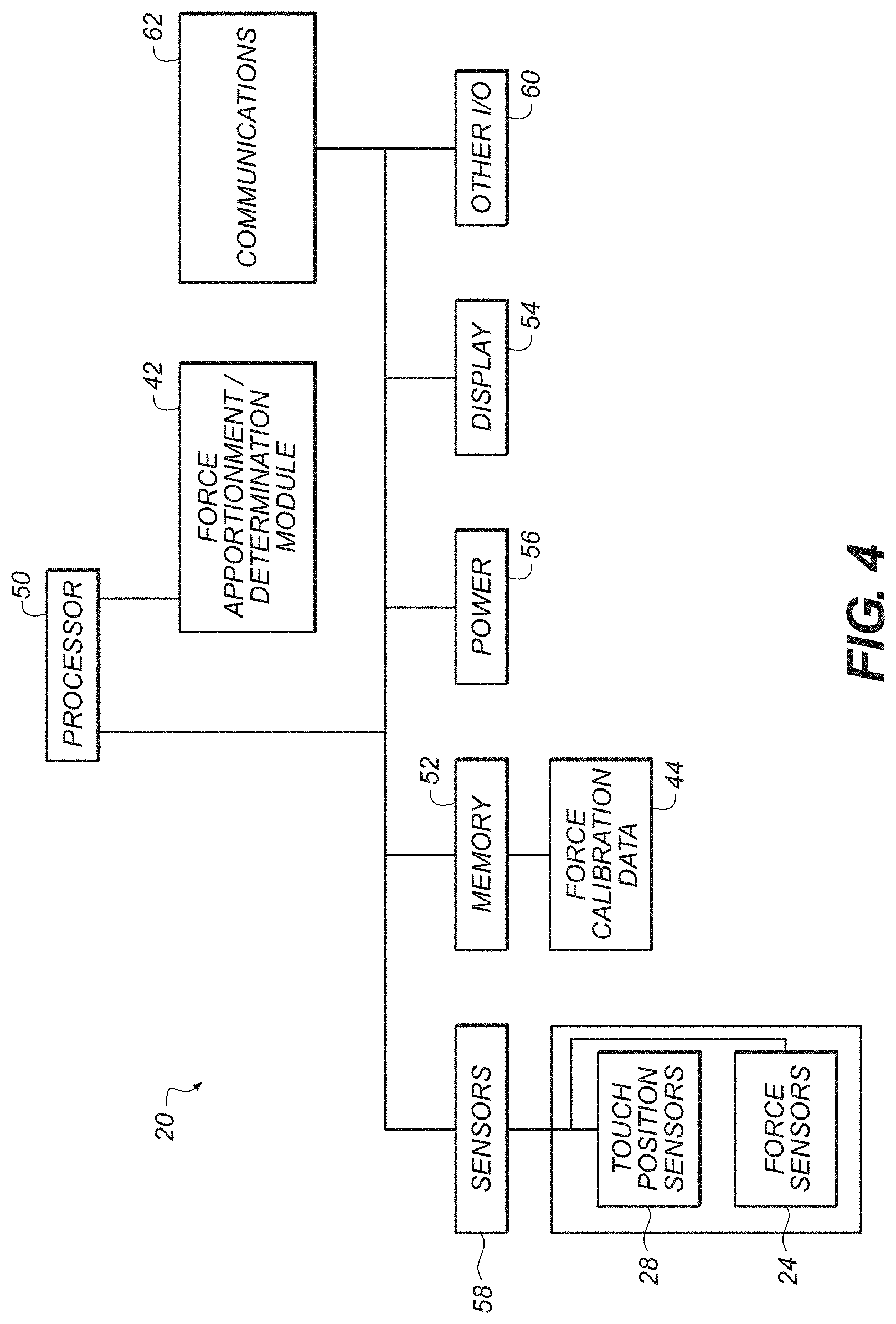
FIG. 4 illustrates an example of a block diagram of an electronic device having a force apportionment module incorporated therein, in accordance with one embodiment of the present disclosure.
FIG. 5 illustrates an example of generating calibration data relating to distribution of forces in response to a unit of force applied to various known locations on a flexible touchscreen of an electronic device, in accordance with one embodiment of the present disclosure.
FIG. 6 illustrates an example of a process for apportioning forces among multiple input fingers depressed upon a flexible touchscreen, in accordance with one embodiment of the present disclosure.
FIG. 7 illustrates an example of force data as received by sensors in response to two fingers of a user depressing upon a flexible touchscreen, in accordance with one embodiment of the present disclosure.
FIG. 8 illustrates an example of Gaussian profiles of forces on a flexible touchscreen, in accordance with one example of the present disclosure.
FIG. 9 illustrates an example of another electronic device having a touch input surface which may incorporate embodiments of the present disclosure.
FIGS. 10A-C illustrate an example of improving matched filter accuracy to account for possible drops of a device, in accordance with one example of the present disclosure.
FIGS. 11A-E illustrate another example of improving matched filter accuracy to account for possible drops of a device, in accordance with one example of the present disclosure.
DETAILED DESCRIPTION
Disclosed herein are various examples of mechanisms to detect the location and the amount of force imparted by one or multiple fingers of a user onto a touch-sensing input surface of an electronic device. The mechanisms can provide, as outputs, coordinates of the location of a user's fingers on the touch input device when a depression was detected, as well as values representing the forces of each of the depressions attributable to each user's fingers. In this manner, if a user depresses the touch input device with two fingers simultaneously in different locations with the same or differing amounts of force, embodiments of the present disclosure can detect those two depressions, determine the coordinates of both depressions, and determine the amounts of force corresponding to each of the two depressions.
Embodiments of the present disclosure can be utilized in various electronic devices, such as (in one non-limiting example) as or in conjunction with a touchscreen of a mobile phone or tablet computer or other portable electronic device (see, e.g., devices 20 in FIGS. 1-2, 9). In another example, a touchpad/trackpad input device can be formed utilizing one or more features, operations, or structures of the present disclosure.
In one example, the greater the force used by the user in depressing the input device, the more quickly a corresponding action occurs in the electronic device, such as scrolling faster, moving faster through a video, highlighting text in a quicker manner, and the like.
Referring to FIGS. 1-2, in one example, an electronic device 20 having a touch-sensing input surface 22 is provided with a plurality or array of force sensors 24 (FIG. 2). For instance, force sensors 24 may be arranged as a perimeter array of sensors, a full array of sensors distributed about the surface 22 of an electronic device 20, or any combination thereof. The sensor locations are known and fixed relative to the touch input surface 22 of an electronic device 20. The force sensors 24 may be one or more strain gauges, capacitive force sensors, pressure sensors, and the like. For example, one embodiment may employ capacitive plates aligned parallel to one another, such that a force exerted on the input surface 22 moves the plates closer to one another. This change in distance between the plates may yield an increased capacitance between the plates. The changes in capacitance may, in turn, be correlated to an amount of force exerted on the input surface 22.
Generally, it should be appreciated that the embodiments disclosed herein may be used with any type of force sensor, and so the foregoing examples are intended to be non-limiting.
An electronic device 20 may include a touch input surface 22, such as a touchscreen. In one example and referring to FIG. 2, a touch input surface 22 of an electronic device 20 may include a flexible glass or transparent layer 26, a plurality of touch location sensors (an example of a touch location that has been detected by a touch location sensor is shown in FIG. 2 as 28), and a plurality of force sensors 24 distributed proximate the touch input surface. The flexible glass layer 26 may have, in one example, portions (e.g., edges) that are suspended relative to the main body or housing 30 of the electronic device 20, and the flexible glass portion 26 may deflect or bend upon a user applying or depressing the touch input surface 22 using one or more fingers at one or more locations on the touch input surface 22.
As force is applied to the touch input surface 22 by a user's finger, the applied force spreads across the input surface and the force response (for example, deflection measurement values, capacitance, strain and the like) as measured by the force sensor or sensors 24 may look like a bell curve (as shown in FIG. 7).
Given a set of touch locations, embodiments of the present disclosure aid in determining or apportioning the relative forces contributed by each touch of a user's finger on a touch input surface 22. By determining the amount of force associated with each touch of a user's finger on a touch input surface 22, such information can be utilized by the electronic devices processor (FIG. 4) to perform a variety of functions or operations for the benefit of the user. It should be appreciated that a user's touch location may be determined through the use of any of various touch-sensing technologies, such as capacitive sensing, resistive sensing, thermal sensing, and so on. Accordingly, the details of technologies designed to sense the location of a touch are not described in more detail herein.
If desired, a variety of features and functions described herein can be integrated into an input device 40 which may be incorporated within electronic device 20. Referring to FIG. 3, one example of an input device 40 is illustrated, which includes a plurality of touch position sensors 28 and a plurality of force sensors 24. As previously discussed, the touch position sensors 28 and force sensors 24 may be any of a variety of different sensors employing different sensing technologies. The input device 40 may also include a force apportionment module 42 which receives, as inputs, position information (such as (x, y) touch coordinates) from the touch position sensors 28, and force data (such as force deflection measurement values) from the plurality of force sensors 24. The force apportionment module 42 may also receive force calibration data 44, representing the expected amount of force received by a plurality of force sensors 24 in response to a fixed unit of force applied across various known locations of the input device 40 and/or electronic device 20. A matched filter module 46 may also be provided in order to aid in the determination of the amount of forces to be apportioned to each depression of a user's fingers of the input device 40.
The force apportionment module 42 may be configured to implement one or more operations, processes (or portions thereof), features or functions as described herein. In one example, the force apportionment module 42 determines or apportions a first amount of force as measured by the plurality of force sensors 24 to one of at least two fingers, and determines or apportions a second amount of force as measured by the plurality of force sensors 24 to another of the at least two fingers.
The input device 40 may provide, as outputs 46, 48 of the force apportionment module, the position and force attributable to the depression by a user of a user's finger (shown as 46), and the position and force attributable to the depression by a user of another one or more of a user's finger (shown as 48). For instance, where a user employs two fingers at different locations to touch the input device, the input device 40 of FIG. 3 can generate as outputs, the position and forces attributable to the depressions of each of the user's two fingers. These outputs 46, 48 can be passed to the processor(s), logic, or other components or modules of the electronic device 20 that is interacting with the input device 40 of FIG. 3.
In one example, matched filter techniques (for instance, as described herein) may be utilized by module 46 to determine forces contributed by each touch of one or more fingers of a user on a touch input device 40 of an electronic device 20.
In one embodiment of the present disclosure and still referring to FIG. 3, a library of data 44 is maintained in the electronic device 20 which includes force calibration data representing the force deflection measurement values as measured by each of a plurality of force sensors 24 (such as 24 or representative versions of sensors 24), in response to a standardized force applied to various known locations on a touch input surface (such as 22 or representative versions of touch input surface 22). In one example and referring to FIG. 5, to form the calibration data 44, a robot or other mechanized, repeatable process may be utilized to apply a known amount of force (for example, the same amount of force) to different known locations on a touch input surface, and for each touch location, force deflection measurement values as reported by each of the force sensors is stored in the library 44. In effect, this library of data 44 forms a map (e.g., FIG. 8A) of deflections as a function of sensor locations for a given touch location (X, Y). This library 44 may be stored in the electronic device 20 in any form, such as but not limited to a matrix, a table, a lookup table, a database, parametric representations, or in the form of any other data structure.
An input device 40 in accordance with embodiments of the present disclosure may be stand-alone devices (such as a standalone track pad), or may be incorporated into electronic devices 20 such as mobile phones, tablet computers, or other portable electronic devices. FIG. 4 illustrates an example of a block diagram of an electronic device 20 having a force apportionment module 42 incorporated therein, in accordance with one embodiment of the present disclosure. In the example of FIG. 4, an electronic device 20 includes a processor 50 coupled with and in communications with a memory 52, a display 54, power circuitry 56, and one or more sensors 58, input/output devices 60, and communication modules 62 coupled with processor 50. The sensors 58 may include a plurality of touch position sensors 28, and a plurality of force sensors 24. The memory 52 may include a persistent memory or data structure including force calibration data 44 representing the expected amount of force received by a plurality of force sensors in response to a fixed unit of force applied across various known locations of the input device.
In one example in FIG. 4, the processor 50 may include a force apportionment module 42 that interacts with and receives data from the position sensors 28, force sensors 24, and the force calibration data 44. The force apportionment module 42 may be configured to implement one or more operations, processes (or portions thereof), features or functions as described herein. The force apportionment module 42 can determine, in one example, the position and force attributable to the position and force attributable to the depression by a user of a user's finger, and the position and force attributable to the depression by a user of another one or more of a user's finger.
FIG. 5 illustrates an example of various calibration techniques in accordance with an embodiment of the present disclosure. At operation 500, a robot or other device applies a known amount of force to a specified location (an example location 501 is shown in FIG. 5) on a touch input surface 22 of an electronic device 20. At operation 505, deflection maps for all touch locations are analyzed. In other words, the force measurement values, as detected by each force sensor 24 of the electronic device 20 in response to the robotic touch of operation 500, are recorded.
It should be appreciated that the force sensors 24 may not be at or adjacent the location at which force is applied. Nonetheless, the force sensors 24 may register the force insofar as the input surface may be at least somewhat deformable, thereby permitting force exerted at one point to be spread over a region. Thus, force sensors 24 nearest the force application location may register a higher force than force sensors that are further away from the force application location. Since the registered force may decrease with the distance between the force sensor 24 and force application location, force sensors that are sufficiently removed from the force application location may register no, or almost no, force.
Operations 500-505 are repeated for differing locations (other than at 501) on the touch input surface 22 where the robot applies the known amount of force, until a sufficient amount of data has been gathered representing the regions which a user could touch the touch input surface during use. Each force sensor 24 may thus generate a force map, formed from various measurements of known forces at various known locations on touch input surface 22. Generally, each force sensor's force map is different from the force maps of the other force sensors, reflecting the variances in positioning of the force sensors within the electronic device. Force maps may also, in some circumstances, reflect differences between each individual force sensor, such as sensitivity, construction and the like.
In this manner, a two-dimensional distribution of calibration data (the force map) can be formulated, such as shown at 510. In this disclosure a force map (represented in certain equations by the variable "G") (e.g. FIG. 8B) represents what an expected force response should be at a given touch location for a given force input value. Through the use of the force map, forces exerted at known touch locations, as provided via the touch sensors, may be correlated to force inputs. This information may be used to apportion an overall detected force between multiple touch locations.
FIG. 6 illustrates an example of a process for apportioning forces among multiple input fingers exerting force on a flexible input surface, in accordance with one embodiment of the present disclosure. ("Flexible or "deformable" may refer to any substance or surface that will deform locally under a load rather than moving uniformly as a rigid body. Glass, for example, may be flexible/deformable.) These operations, or portions thereof, may be utilized within an electronic device, in one example. At operation 600, one or more touch input conditions are detected. For instance, operation 600 may include the detection of a touch on an touch input surface of an input device, or may detect multiple touches on a surface of an input device.
At operation 605, the locations of touches detected by operation 600 are determined. In one example, operation 605 receives or obtains location information (e.g., (x, y) coordinates) of a first touch location on the surface of a touch input device. At operation 610, the location of a second touch, if present, is determined; in some embodiments, operations 605 and 610 are combined or otherwise occur substantially simultaneously. In one example, operation 610 receives location information (e.g., (x, y) coordinates of a second touch location. If other touches (e.g., a third touch from a third finger) are detected that occur substantially together in time with the first touch and the second touch, the locations of those other touches are also determined from the touch sensors.
At operation 620, the amounts of force attributable to each touch on the touch input device are determined. Operation 620 may be performed utilizing a number of different methodologies. In one example, operations 620A-620C are utilized to determine the amounts of force attributable to each touch. These operations may be performed iteratively on some or all of the touch force sensors of the touch input device of the electronic device, in one example.
At operation 620A, the force value at a force sensor at a particular location is obtained. In one example, an input in response to a finger touch, as measured by a force sensor at a particular location, is obtained or read by operation 620A. This input may be correlated to a force experienced by the particular force sensor.
At operation 620B, the force map data for the force sensor of operation 620A is retrieved or otherwise obtained. The force maps generated by each force sensor are generally described above.
At operation 620C, the force attributable to each finger touch location on the touch input device at the force sensor location is determined. In one example, as described herein, operation 620C may utilize a matched filter process in order to determine the amount of force attributable to each finger depression on the input touch device at the particular force sensor location.
Operations 620A-620C may be repeated for each force sensor location of the touch input device, in one example.
Hence it can be seen that the operations of FIG. 6 provide, for each touch detected, the touch location and the force attributable to the touch. This information can be utilized within the electronic device for a variety of purposes, such as but not limited to those purposes as described herein.
Matched Filters
In one embodiment, an entire force profile of the touch input surface is characterized as a vector, and its dot product with actual force response data at a particular force sensor location is calculated, along with other touch location's predicted force responses and their dot products with the actual force response measurements at those other locations. The result can be isolated to determine the amount of force attributed to a user's first finger; and the result can be isolated to determine the amount of force attributed to a user's second finger; and if more touches from more than two fingers are detected, the forces attributed to the additional fingers can be determined. That is, the operation may attribute individual forces to individual touch locations, as vectors, thereby estimating the forces applied at each touch location from an overall applied force.
Dot products are useful in manipulating or determining values based on vectors, wherein the result of a dot product operation is a scalar quantity. For instance, for vectors (a, b), "a dot b" can be represented as (magnitude of a).times.(magnitude of b).times.cosine(theta), where theta is the angle between the vectors a, b. Another way of expressing of "a dot b" is (ax.times.bx)+(ay.times.by).
Matched Filters for Two-Finger Touch Inputs
In one example, a matched filter is utilized to determine the amount of force (f.sub.1, f.sub.2, f.sub.n) attributable to each finger depression (1, 2, . . . N) upon the touch input surface. A linear set of equations can be used:
##EQU00001## where
s.sub.i represents present/current force deflection measured by sensor i=1 . . . N
g.sub.i represents deflection expected for sensor i, for unit force at A (see FIGS. 7-8)
h.sub.i represents deflection expected for sensor i, for unit force at B (see FIGS. 7-8)
The values for g.sub.i and h.sub.i may be obtained from the library of force calibration data, in one example, for each force sensor. The force (f.sub.1, f.sub.2, f.sub.n) attributable to each finger's depression onto the touch input surface can be determined using the following example operations: f.sub.1=(.SIGMA.s.sub.ig.sub.i.SIGMA.h.sub.i.sup.2-.SIGMA.s.sub.ih.sub.i.- SIGMA.g.sub.ih.sub.i)/.DELTA. f.sub.2=(-.SIGMA.s.sub.ig.sub.i.SIGMA.g.sub.ih.sub.i+.SIGMA.s.sub.ih.sub.- i.SIGMA.g.sub.i.sup.2)/.DELTA. .DELTA.=.SIGMA.g.sub.i.sup.2.SIGMA.h.sub.i.sup.2-(.SIGMA.g.sub.ih.sub.i).- sup.2
For N sensors, there can be N equations in one embodiment.
In some special cases of the above equations, when for example, the user's two fingers are close to each other, the expected deflection maps produced by both fingers are similar (g.sub.i is approximately h.sub.i), and the denominator vanishes (.DELTA. approaches 0). The equations for f.sub.1 and f.sub.2 become highly unstable, and any perturbations (for example, measurement noise) in s.sub.i will be highly amplified, contributing to large force reconstruction errors. The constant .lamda. may be introduced to keep the equation stable and without discontinuities.
For example, in case of two fingers detected as contacting the display 22, the system of linear equations can be written as:
.lamda..times..times..times..times..lamda..times. ##EQU00002## f.sub.1=(.SIGMA.s.sub.ig.sub.i(.SIGMA.h.sub.i.sup.2+.lamda.)-.SIGMA.s.sub- .ih.sub.i.SIGMA.g.sub.ih.sub.i)/.DELTA..sub..lamda. f.sub.2=(-.SIGMA.s.sub.ig.sub.i.SIGMA.g.sub.ih.sub.i+.SIGMA.s.sub.ih.sub.- i).SIGMA.g.sub.i.sup.2+.lamda.))/.DELTA..sub.80 .DELTA..sub..lamda.=.SIGMA.g.sub.i.sup.2.SIGMA.h.sub.i.sup.2-(.SIGMA.g.su- b.ih.sub.i).sup.2+.lamda.(.SIGMA.g.sub.i.sup.2+.SIGMA.h.sub.i.sup.2)+.lamd- a..sup.2
The denominator .DELTA..sub..lamda. no longer vanishes when g.sub.i is approximately h.sub.i, and the solution becomes stable with respect to measurement perturbations. While improving the stability of the solution, the regularization parameter .lamda. also degrades the accuracy of force reconstruction (due to the additional terms in the equations for f.sub.1 and f.sub.2)
In order to preserve the reconstruction accuracy in cases when solution is otherwise stable and regularization is not required, it is possible to vary the magnitude of .lamda., depending on, for example, the distance between the fingers, or their location on the screen 22. One example of an adaptive regularization parameter is:
.lamda..function..lamda..times..times..lamda..times..times..lamda..times.- .times..lamda..times..times..lamda..times..times..times..times.e ##EQU00003##
where r is the distance between the fingers. For small distances (r<r.sub.o), the function assumes a maximal value .lamda..sub.max yielding high amounts of regularization: solution stability is increased at the cost of force reconstruction accuracy (total applied for will be distributed equally between the two fingers, in this example).
For large separation distances (r>r.sub.o) between the fingers that touch display 22, when the solution is stable, the regularization is minimal (.lamda.(r)=.lamda..sub.min) and force reconstruction accuracy is improved.
For distances where r approximately equals r.sub.o, the regularization parameter .lamda. is reduced smoothly (e.g., within a fuzzy window +/-w) to balance force reconstruction accuracy and stability.
In other words, the constant .lamda. may be used to compensate for system irregularities that may otherwise cause the equations to return inaccurate of erroneous results.
In more general cases of K fingers, the regularization parameter .lamda. may be introduced as:
.lamda..lamda. .lamda. ##EQU00004##
where g.sub.n,k is the expected response of sensor n for a unit force at the location of finger k.
Matched Filter for a Single Finger Touch Inputs
The force (f) attributable to a single finger's depression onto a touch input surface can be determined using the following example operations:
.times..times..times. ##EQU00005## where
s.sub.i represents the present/current deflection measured by sensor i=1 . . . N
g.sub.i represents deflection expected for sensor i, when a unit force is applied at a given location.
The values for g.sub.i may be obtained from the library of force calibration data, in one example, for each force sensor.
N can either be equal to the total number of sensors, or represent a small group of sensors around the touch location(s). The choice may vary between embodiments, and may be based on a number of factors, such as the size of the embodiment, the spacing of the force sensors, the material(s) used for the input surface, other physical properties of the input surface (such as flexibility), and the like.
In another embodiment, data from sub-clusters of force sensors can be grouped together and averages of their data can be determined before applying the dot product operations. For instance, data clusters of (2 force sensors by 2 force sensors) can be formed using the deflection measurement values from force sensors. This can reduce the number of dot product calculations to be performed, which can reduce the run-time complexity and reduce the memory requirements for the processor to perform the processes disclosed herein, but results in less accurate resultant data as to force values. In another example, force sensors (or their outputs) may be sorted by the magnitudes of their expected signals (which may be obtained from calibration data, as one example), and a dot product operation applied to the expected and measured values comprising pairwise differences between the sensors having expected largest and smallest values. Such a grouping may be used, for example, in a single finger force reconstruction scenario to mitigate the effects of common-mode and/or spatially correlated noise that may be present in sensor outputs.
In another example, for two or more finger inputs (where k=the number of fingers), the expression G dot f=S can be used, wherein G is expressed as a column vector having m rows corresponding to the number of sensors, G has columns corresponding to the number of fingers. Since this expression has, in practice, more rows than columns, a least-squared process can be used to minimize [[(G dot f)-s]], wherein G is expressed as a matrix of (m by k) and f is a force vector of (k by 1). From this, values for f can be determined for each finger k.
Accordingly, it can be seen that embodiments of the present disclosure provide for the apportionment of measured forces applied by multiple fingers of a user to a touch input surface of an electronic device. In this way when a user touches a touch input surface with two or more fingers, a determination can be made of the amount of force applied by each finger to the touch input surface. This determination can be useful for providing the electronic device with additional dimensions of user input and control to the device, which can be used to enhance the user's experience and interaction with the electronic device.
In another embodiment of the present disclosure, the accuracy of match filters may be further enhanced, if desired, to account for possible damage that may occur to the electronic device (e.g., device 22 or 40). Certain events during a life time of a device may cause boundary conditions to change, which can lead to significant differences between the expected and observed deflection maps.
In some cases, it may be possible to partially compensate for these changes, for example, by changing the weights (or levels of trust) in the readings of certain affected sensors. In one example, the trust in the values from around the edges of input surface 22 are minimized (based on that after a drop of the device, those edge sensors may be adversely affected), and the trust in the sensors towards the center of the input surface 22 are increased (as these sensors are likely intact after a drop of the device). For instance, for a system of equations:
##EQU00006##
In one example, instead of minimizing
.times. ##EQU00007##
a minimization operation can be performed on (f):
.times. ##EQU00008##
Dynamic weights that can be related to, for example: (a) current location of the deflection centroid, (b) shift of the current deflection centroid from its expected location for a given touch, (c) distance of the sensing pixel from the device borders (as to reduce the dependence on the boundary conditions), or other metric that indicates the level of trust in the output of particular sensors.
In one example, changing the weights (or levels of trust) in the readings of certain affected sensors around the expected centroid can be upweighted, and pixels around the observed (shifted) centroid can be deweighted. In another example, changing the weights (or levels of trust) in the readings of certain affected sensors can be achieved by upweighting the sensors close to the center of the screen 22.
For instance, FIG. 10A shows in the left image an example of a deflection map with intact borders; while the right image in FIG. 10A shows an example deflection map in a situation where the border has been broken such as where a break has occurred near the top left corner of the device, and a user finger press is near the top left corner.
FIGS. 10B and 10C then show possible distributions of weights "w" per equation above in paragraph [0089]. FIG. 10B illustrates an example where the old centroid has been upweighted, and the new centroid is deweighted.
In another example, FIG. 10C illustrates an example where screen center sensor readings have been upweighted, thereby putting more trust into sensors away from the device boundaries.
In another example of the present disclosure, matched filter accuracy improvement may be achieved via border sensor subtraction, in order to aid in situations where sensors may have been damaged due to drops of the device.
For instance, certain breaks in device boundaries may lead to a significant compliance increase for the touches in the vicinity of that boundary. For those touches, the deflection centroid shifts towards the break, and the deflection profile resembles that of a partially supported plate (e.g., plate with force sensors 24) with a free boundary section. It may be possible to partially compensate for these boundary condition breaks by subtracting the "cantilever" mode from the observed deflections. The cantilever mode may be determined by fitting a representative parametric shape to the deflections observed by the boundary sensors.
For example, the border sensors are no longer part of the weighted least squares estimation. The magnitude of the subtracted cantilever mode can be further scaled in proportion to the deflection centroid shift. Cantilever mode may be approximated by a 2D Gaussian, centered outside of the screen active area. In FIG. 11A, an example of a calibrated deflection map is shown where the device borders are intact. In FIG. 11B, an example of a deflection map is shown where a broken border exists at the top left of the device display, and the centroid shifts and compliance increases. In FIG. 11C, an example is shown where a "cantilever" fit mode is used using data from the border sensors. In FIG. 11D, the canteliever mode is propagated into the interior. In FIG. 11E, the adjusted map is shown wherein the cantilever mode has been subtracted from the observed deflection map of FIG. 11B.
While embodiments of the disclosure have been described with reference to a tablet computer or a mobile phone, it is understood that embodiments of the present disclosure can be utilized with a variety of electronic devices including but not limited to mobile devices, mobile phones, tablet computers, music and multi-media players, watches, gaming devices, and other handheld, wearable or portable devices.
While the methods disclosed herein have been described and shown with reference to particular operations performed in a particular order, it will be understood that these operations may be combined, sub-divided, or re-ordered to form equivalent methods without departing from the teachings of the present disclosure. Accordingly, unless specifically indicated herein, the order and grouping of the operations is not a limitation of the present disclosure.
It is understood that the directional references provided herein, such as top, bottom, upwards, downwards, clockwise, counterclockwise, left, right, and the like, are provided to describe examples of the embodiments disclosed herein, and are not intended to be limiting.
It should be appreciated that in the foregoing description of exemplary embodiments of the disclosure, various features of the disclosure are sometimes grouped together in a single embodiment, figure, or description thereof for the purpose of streamlining the disclosure and aiding in the understanding of one or more of the various aspects. This method of disclosure, however, is not to be interpreted as reflecting an intention that the claims require more features than are expressly recited in each claim. Rather, inventive aspects lie in less than all features of a single foregoing disclosed embodiment, and each embodiment described herein may contain more than one inventive feature.
While the disclosure is presented and described with refe
References
D00000
D00001
D00002
D00003
D00004
D00005
D00006
D00007
D00008
D00009
D00010
D00011
D00012

D00013

D00014

M00001

M00002

M00003
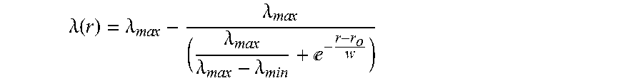
M00004

M00005

M00006

M00007

M00008

XML
uspto.report is an independent third-party trademark research tool that is not affiliated, endorsed, or sponsored by the United States Patent and Trademark Office (USPTO) or any other governmental organization. The information provided by uspto.report is based on publicly available data at the time of writing and is intended for informational purposes only.
While we strive to provide accurate and up-to-date information, we do not guarantee the accuracy, completeness, reliability, or suitability of the information displayed on this site. The use of this site is at your own risk. Any reliance you place on such information is therefore strictly at your own risk.
All official trademark data, including owner information, should be verified by visiting the official USPTO website at www.uspto.gov. This site is not intended to replace professional legal advice and should not be used as a substitute for consulting with a legal professional who is knowledgeable about trademark law.