Variable magnification optical system, optical apparatus, and method for manufacturing variable magnification optical system
Harada J
U.S. patent number 10,527,829 [Application Number 15/545,702] was granted by the patent office on 2020-01-07 for variable magnification optical system, optical apparatus, and method for manufacturing variable magnification optical system. This patent grant is currently assigned to Nikon Corporation. The grantee listed for this patent is Nikon Corporation. Invention is credited to Hiroki Harada.


View All Diagrams
| United States Patent | 10,527,829 |
| Harada | January 7, 2020 |
Variable magnification optical system, optical apparatus, and method for manufacturing variable magnification optical system
Abstract
A variable magnification optical system includes: a first lens group (G1) having a negative refractive power; a second lens group (G2) having a positive refractive power; an intermediate group (Gn) disposed closer to an image side than the second lens group (G2); and a vibration-reduction lens group (VR) disposed closer to the image side than the intermediate group (Gn) and configured to be movable so as to have a component in a direction orthogonal to an optical axis. The system performs varying magnification by changing at least the distance between the first lens group (G1) and the second lens group (G2) and the distance between the second lens group (G2) and the intermediate group (Gn), and the system satisfies Conditional Expression (1). 1.000<f(1.about.Gn)t/ft<100.000 (1)
| Inventors: | Harada; Hiroki (Zushi, JP) | ||||||||||
|---|---|---|---|---|---|---|---|---|---|---|---|
| Applicant: |
|
||||||||||
| Assignee: | Nikon Corporation (Tokyo,
JP) |
||||||||||
| Family ID: | 56543542 | ||||||||||
| Appl. No.: | 15/545,702 | ||||||||||
| Filed: | January 29, 2016 | ||||||||||
| PCT Filed: | January 29, 2016 | ||||||||||
| PCT No.: | PCT/JP2016/052683 | ||||||||||
| 371(c)(1),(2),(4) Date: | December 09, 2017 | ||||||||||
| PCT Pub. No.: | WO2016/121939 | ||||||||||
| PCT Pub. Date: | August 04, 2016 |
Prior Publication Data
| Document Identifier | Publication Date | |
|---|---|---|
| US 20180136444 A1 | May 17, 2018 | |
Foreign Application Priority Data
| Jan 30, 2015 [JP] | 2015-017916 | |||
| Current U.S. Class: | 1/1 |
| Current CPC Class: | G02B 13/18 (20130101); G02B 15/20 (20130101); G03B 5/00 (20130101); G02B 27/646 (20130101); G02B 15/177 (20130101) |
| Current International Class: | G02B 15/177 (20060101); G03B 5/00 (20060101); G02B 15/20 (20060101); G02B 27/64 (20060101); G02B 13/18 (20060101) |
| Field of Search: | ;359/432 |
References Cited [Referenced By]
U.S. Patent Documents
| 5477297 | December 1995 | Suzuki |
| 5502594 | March 1996 | Suzuki |
| 5585966 | December 1996 | Suzuki |
| 5642224 | June 1997 | Suzuki |
| 5760957 | June 1998 | Suzuki |
| 5841588 | November 1998 | Suzuki |
| 5940631 | August 1999 | Hirano |
| 6025962 | February 2000 | Suzuki |
| 7907350 | March 2011 | Mitsuki |
| 10209499 | February 2019 | Shibata |
| 2004/0218274 | November 2004 | Aoki |
| 2005/0219708 | October 2005 | Shibayama |
| 2006/0072213 | April 2006 | Shibayama |
| 2007/0195425 | August 2007 | Arai |
| 2007/0206294 | September 2007 | Kanai |
| 2009/0086321 | April 2009 | Mizuguchi |
| 2010/0165480 | July 2010 | Yamaguchi et al. |
| 2010/0214658 | August 2010 | Ito |
| 2012/0026589 | February 2012 | Tanaka et al. |
| 2012/0069441 | March 2012 | Fujimoto et al. |
| 2012/0188436 | July 2012 | Ozaki |
| 2012/0229902 | September 2012 | Matsumura |
| 2014/0028891 | January 2014 | Otake et al. |
| 2014/0211082 | July 2014 | Imaoka |
| 2014/0362259 | December 2014 | Yamada |
| 2015/0153550 | June 2015 | Yamaguchi et al. |
| 2018/0196223 | July 2018 | Umeda |
| 11-231220 | Aug 1999 | JP | |||
| 2004-061679 | Feb 2004 | JP | |||
| 2004-246043 | Sep 2004 | JP | |||
| 2007-233045 | Sep 2007 | JP | |||
| 2008-216881 | Sep 2008 | JP | |||
| 2010-152145 | Jul 2010 | JP | |||
| 2011-215600 | Oct 2011 | JP | |||
| 2012-198505 | Oct 2012 | JP | |||
| 2012-247687 | Dec 2012 | JP | |||
| 2013-064912 | Apr 2013 | JP | |||
| 2014-026169 | Feb 2014 | JP | |||
| 2014-160229 | Sep 2014 | JP | |||
| WO 2011/145288 | Nov 2011 | WO | |||
| WO 2014/025015 | Feb 2014 | WO | |||
Other References
|
Office Action dated Nov. 28, 2017 in Japanese Patent Application No. 2016-572188. cited by applicant . Extended European Search Report dated Oct. 8, 2018, in European Patent Application No. 16743542.9. cited by applicant . Decision of Refusal dated Sep. 4, 2018, in Japanese Patent Application No. 2016-572188. cited by applicant . International Search Report from International Patent Application No. PCT/JP2016/052683, dated Apr. 26, 2016. cited by applicant . Written Opinion of the International Searching Authority from International Patent Application No. PCT/JP2016/052683, dated Apr. 26, 2016. cited by applicant . Office Action dated May 5, 2019, in Chinese Patent Application No. 201680016761.3. cited by applicant . Office Action dated Oct. 8, 2019 in Japanese Patent Application No. 2018-226455. cited by applicant. |
Primary Examiner: Font; Frank G
Attorney, Agent or Firm: Shapiro, Gabor and Rosenberger, PLLC
Claims
The invention claimed is:
1. A variable magnification optical system comprising: a first lens group having a negative refractive power; a second lens group having a positive refractive power; an intermediate group disposed closer to an image side than the second lens group; and a vibration-reduction lens group disposed closer to the image side than the intermediate group and configured to be movable so as to have a movement component in a direction orthogonal to an optical axis, wherein the system performs varying magnification by changing at least the distance between the first lens group and the second lens group and the distance between the second lens group and the intermediate group, and the system satisfies the following conditional expression: 1.500<f(1.about.Gn)t/ft<100.000 where f(1.about.Gn)t: a composite focal length from the first lens group to the intermediate group in a telephoto end state ft: a focal length of the entire system in the telephoto end state.
2. The variable magnification optical system according to claim 1, wherein the system satisfies the following conditional expression: 1.360<-f(Gn.about.G(VR))w/fw<5.000 where f(Gn.about.G(VR))w: a composite focal length from the intermediate group to the vibration-reduction lens group in a wide-angle end state fw: a focal length of an entire system in the wide-angle end state.
3. The variable magnification optical system according to claim 1, wherein the system includes an image-side lens group having the strongest positive refractive power among lens groups which are disposed closer to the image side than the vibration-reduction lens group and have positive refractive power, the distance between the image-side lens group and the vibration-reduction lens group changes upon varying magnification, and the system satisfies the following conditional expression: 0.400<f(RP)/f(FP)<2.000 where f(RP): a focal length of the image-side lens group f(FP): a composite focal length in the wide-angle end state, of lenses disposed closer to the image plane side than the first lens group and disposed closer to the object side than the intermediate group.
4. The variable magnification optical system according to claim 1, wherein the intermediate group has negative refractive power and of which the position in the direction orthogonal to the optical axis is fixed.
5. The variable magnification optical system according to claim 1, wherein the intermediate group has one or more positive lens components and one or more negative lens components.
6. The variable magnification optical system according to claim 1, wherein the second lens group includes at least four lens components.
7. The variable magnification optical system according to claim 1, wherein the second lens group is constituted by, in order from the object, a 2-1st lens group having a positive refractive power and a 2-2nd lens group having a positive refractive power, and the 2-1st lens group is moved toward the image side as a focusing lens group to perform focusing from an object at infinity to an object at a close distance.
8. An optical apparatus having the variable magnification optical system of claim 1 mounted thereon.
9. A method for manufacturing a variable magnification optical system, wherein the variable magnification optical system comprises: a first lens group having a negative refractive power, a second lens group having a positive refractive power, an intermediate group disposed closer to an image side than the second lens group, and a vibration-reduction lens group disposed closer to the image side than the intermediate group and configured to be movable so as to have a movement component in a direction orthogonal to an optical axis; the system performs varying magnification by changing at least the distance between the first lens group and the second lens group and the distance between the second lens group and the intermediate group; and the method comprises: arranging the respective lens groups in a lens barrel so as to satisfy the following conditional expression: 1.500<f(1.about.Gn)t/ft<100.000 where f(1.about.Gn)t: a composite focal length from the first lens group to the intermediate group in a telephoto end state ft: a focal length of the entire system in the telephoto end state.
10. A variable magnification optical system comprising: a first lens group having a negative refractive power; a second lens group having a positive refractive power; an intermediate group disposed closer to an image side than the second lens group; and a vibration-reduction lens group disposed closer to the image side than the intermediate group and configured to be movable so as to have a movement component in a direction orthogonal to an optical axis, wherein the system performs varying magnification by changing at least the distance between the first lens group and the second lens group and the distance between the second lens group and the intermediate group, (i) the second lens group includes at least four lens components and/or (ii) the second lens group is constituted by, in order from the object, a 2-1st lens group having a positive refractive power and a 2-2nd lens group having a positive refractive power with the 2-1st lens group being movable toward the image side as a focusing lens group to perform focusing from an object at infinity to an object at a close distance, and the system satisfies the following conditional expression: 1.000<f(1.about.Gn)t/ft<100.000 where f(1.about.Gn)t: a composite focal length from the first lens group to the intermediate group in a telephoto end state ft: a focal length of the entire system in the telephoto end state.
11. A variable magnification optical system comprising: a first lens group having a negative refractive power; a second lens group having a positive refractive power; an intermediate group disposed closer to an image side than the second lens group; and a vibration-reduction lens group disposed closer to the image side than the intermediate group and configured to be movable so as to have a movement component in a direction orthogonal to an optical axis, wherein the system performs varying magnification by changing at least the distance between the first lens group and the second lens group and the distance between the second lens group and the intermediate group, the system is constituted by four or five lens groups, and the system satisfies the following conditional expression: 1.000<f(1.about.Gn)t/ft<100.000 where f(1.about.Gn)t: a composite focal length from the first lens group to the intermediate group in a telephoto end state ft: a focal length of the entire system in the telephoto end state.
12. A variable magnification optical system comprising: a first lens group having a negative refractive power; a second lens group having a positive refractive power; an intermediate group disposed closer to an image side than the second lens group; and a vibration-reduction lens group disposed closer to the image side than the intermediate group and configured to be movable so as to have a movement component in a direction orthogonal to an optical axis, wherein the system performs varying magnification by changing at least the distance between the first lens group and the second lens group and the distance between the second lens group and the intermediate group, the intermediate group is moved integrally with the vibration-reduction lens group upon varying magnification, and the system satisfies the following conditional expression: 1.000<f(1.about.Gn)t/ft<100.000 where f(1.about.Gn)t: a composite focal length from the first lens group to the intermediate group in a telephoto end state ft: a focal length of the entire system in the telephoto end state.
13. A method for manufacturing a variable magnification optical system, wherein the variable magnification optical system comprises: a first lens group having a negative refractive power, a second lens group having a positive refractive power, an intermediate group disposed closer to an image side than the second lens group, and a vibration-reduction lens group disposed closer to the image side than the intermediate group and configured to be movable so as to have a movement component in a direction orthogonal to an optical axis; the system performs varying magnification by changing at least the distance between the first lens group and the second lens group and the distance between the second lens group and the intermediate group; and the method comprises: performing at least one of the following steps (A), (B), and (C): (A) configuring the second lens group such that (i) the second lens group includes at least four lens components or (ii) the second lens group is constituted by, in order from the object, a 2-1st lens group having a positive refractive power and a 2-2nd lens group having a positive refractive power, with the 2-1st lens group being movable toward the image side as a focusing lens group to perform focusing from an object at infinity to an object at a close distance, (B) configuring the system to be constituted by four or five lens groups, (C) arranging the intermediate group to be moved integrally with the vibration-reduction lens group upon varying magnification; and arranging the respective lens groups in a lens barrel so as to satisfy the following conditional expression: 1.000<f(1.about.Gn)t/ft<100.000 where f(1.about.Gn)t: a composite focal length from the first lens group to the intermediate group in a telephoto end state ft: a focal length of the entire system in the telephoto end state.
Description
TECHNICAL FIELD
The present invention relates to a variable magnification optical system, an optical apparatus, and a method for manufacturing the variable magnification optical system.
Priority is claimed on Japanese Patent Application No. 2015-017916, filed Jan. 30, 2015, the content of which is incorporated herein by reference.
TECHNICAL BACKGROUND
Conventionally, a variable magnification optical system having a wide angle of view including a camera shake compensation mechanism has been proposed (for example, see Patent Document 1).
RELATED ART DOCUMENTS
Patent Document
Patent Document 1:
Japanese Patent Application, Publication No. H11-231220
SUMMARY OF INVENTION
Technical Problem
In recent years, there has been increasing demand for a variable magnification optical system which has a satisfactory optical performance and has a brighter F-value.
Solution to Problem
According to an aspect of the present invention, there is provided a variable magnification optical system including: a first lens group having a negative refractive power; a second lens group having a positive refractive power; an intermediate group disposed closer to an image side than the second lens group; and a vibration-reduction lens group disposed closer to the image side than the intermediate group and configured to be movable so as to have a component in a direction orthogonal to an optical axis, wherein the system performs varying magnification by changing at least the distance between the first lens group and the second lens group and the distance between the second lens group and the intermediate group, and the system satisfies the following conditional expression. 1.000<f(1.about.Gn)t/ft<100.000
where
f(1.about.Gn)t: a composite focal length from the first lens group to the intermediate group in a telephoto end state
ft: a focal length of the entire system in the telephoto end state
According to another aspect of the present invention, there is provided a variable magnification optical system including, in order from an object: a first lens group having a negative refractive power; a second lens group having a positive refractive power, the first and second lens groups; an n-th lens group which is disposed closer to the image side than the second lens group, of which the position in the direction orthogonal to an optical axis is fixed, and which has negative refractive power; and a vibration-reduction lens group disposed closer to the image side than the n-th lens group and configured to be movable so as to have a component in the direction orthogonal to the optical axis, wherein the system performs varying magnification by changing at least the distance between the first lens group and the second lens group and the distance between the second lens group and the n-th lens group, and the system satisfies the following conditional expression. 1.000<f(1.about.Gn)t/ft<100.000
where
f(1.about.Gn)t: a composite focal length from the first lens group to the n-th lens group in a telephoto end state
ft: a focal length of the entire system in the telephoto end state
According to another aspect of the present invention, there is provided an optical apparatus having the above-described variable magnification optical system mounted thereon.
According to another aspect of the present invention, there is provided a method for manufacturing a variable magnification optical system, wherein the variable magnification optical system includes: a first lens group having a negative refractive power; a second lens group having a positive refractive power; an intermediate group disposed closer to an image side than the second lens group; and a vibration-reduction lens group disposed closer to the image side than the intermediate group and configured to be movable so as to have a component in a direction orthogonal to an optical axis, wherein the system performs varying magnification by changing at least the distance between the first lens group and the second lens group and the distance between the second lens group and the intermediate group, and wherein the method includes arranging the respective lenses in a lens barrel so as to satisfy the following conditional expression. 1.000<f(1.about.Gn)t/ft<100.000
where
f(1.about.Gn)t: a composite focal length from the first lens group to the intermediate group in a telephoto end state
ft: a focal length of the entire system in the telephoto end state
According to another aspect of the present invention, there is provided a method for manufacturing a variable magnification optical system, wherein the variable magnification optical system includes, in order from an object: a first lens group having a negative refractive power; a second lens group having a positive refractive power, the first and second lens groups; an n-th lens group which is disposed closer to the image side than the second lens group, of which the position in the direction orthogonal to an optical axis is fixed, and which has negative refractive power; and a vibration-reduction lens group disposed closer to the image side than the n-th lens group and configured to be movable so as to have a component in the direction orthogonal to the optical axis, wherein the system performs varying magnification by changing at least the distance between the first lens group and the second lens group and the distance between the second lens group and the n-th lens group, and wherein the method includes arranging the respective lens groups in a lens barrel so as to satisfy the following conditional expression. 1.000<f(1.about.Gn)t/ft<100.000
where
f(1.about.Gn)t: a composite focal length from the first lens group to the n-th lens group in a telephoto end state
ft: a focal length of the entire system in the telephoto end state
BRIEF DESCRIPTION OF THE DRAWINGS
FIG. 1 is a cross-sectional view of a variable magnification optical system according to Example 1, wherein parts (W), (M), and (T) are in a wide-angle end state, an intermediate focal length state, and a telephoto end state, respectively.
FIG. 2 shows graphs illustrating various aberrations of the variable magnification optical system according to Example 1 upon focusing on infinity, wherein parts (a), (b), and (c) are in the wide-angle end state, the intermediate focal length state, and the telephoto end state, respectively.
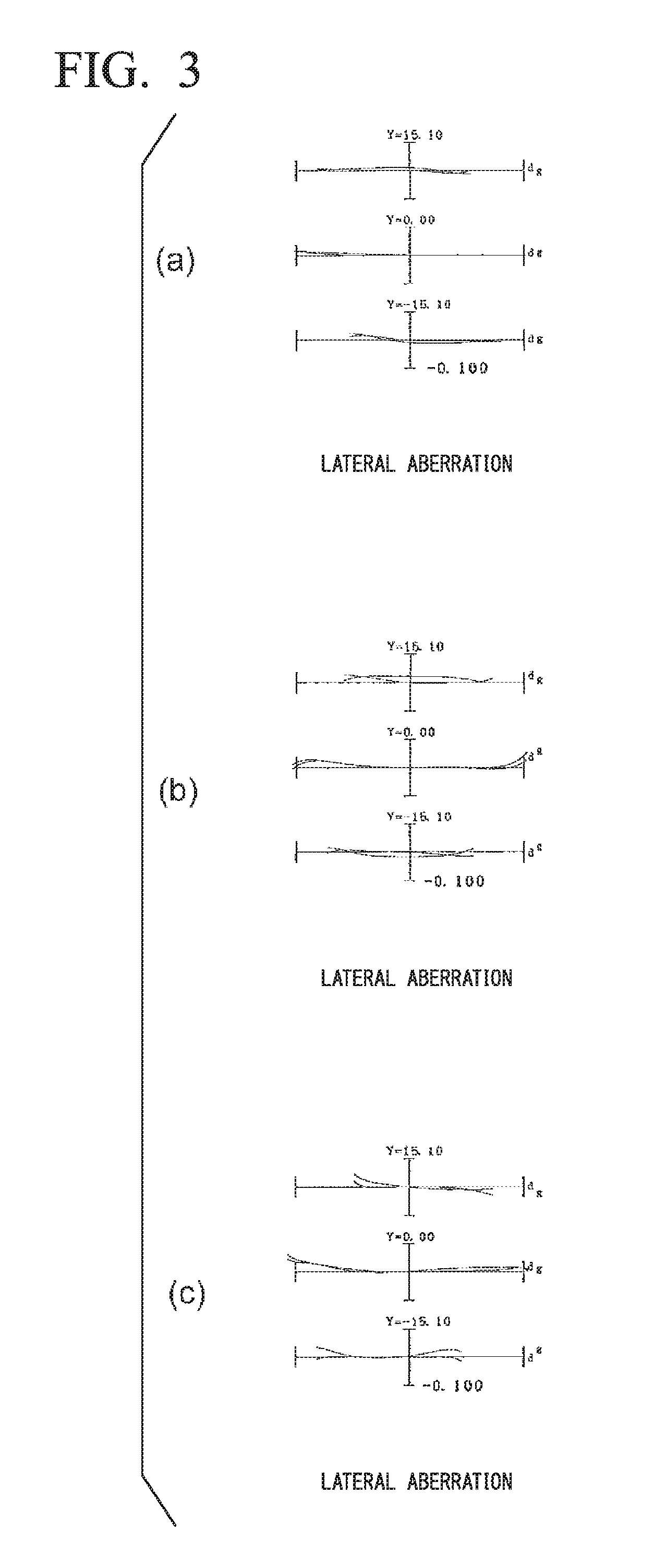
FIG. 3 shows graphs illustrating lateral aberrations of the variable magnification optical system according to Example 1 after image blur correction was performed upon focusing on infinity, wherein parts (a), (b), and (c) are in the wide-angle end state, the intermediate focal length state, and the telephoto end state, respectively.
FIG. 4 is a cross-sectional view of a variable magnification optical system according to Example 2, wherein parts (W), (M), and (T) are in a wide-angle end state, an intermediate focal length state, and a telephoto end state, respectively.
FIG. 5 shows graphs illustrating various aberrations of the variable magnification optical system according to Example 2 upon focusing on infinity, wherein parts (a), (b), and (c) are in the wide-angle end state, the intermediate focal length state, and the telephoto end state, respectively.
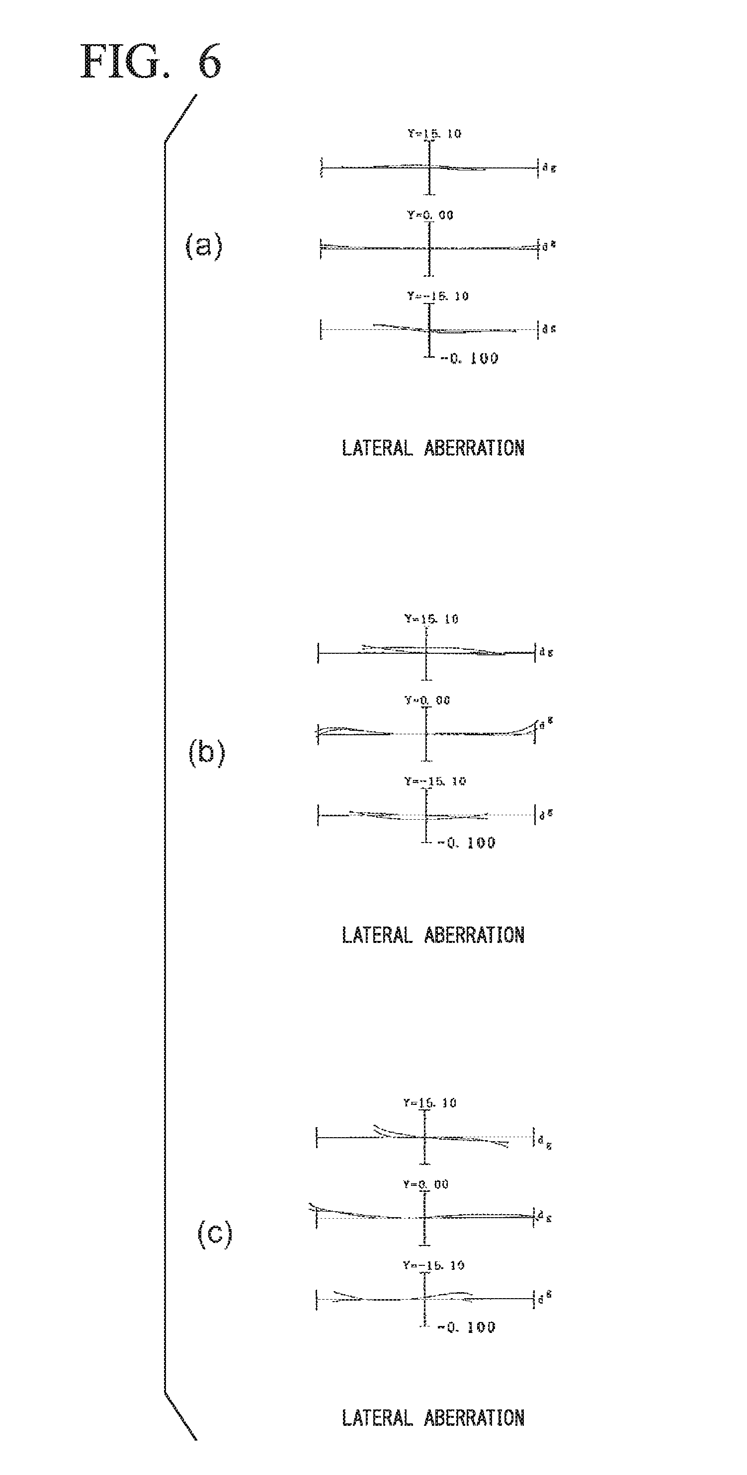
FIG. 6 shows graphs illustrating lateral aberrations of the variable magnification optical system according to Example 2 after image blur correction was performed upon focusing on infinity, wherein parts (a), (b), and (c) are in the wide-angle end state, the intermediate focal length state, and the telephoto end state, respectively.
FIG. 7 is a cross-sectional view of a variable magnification optical system according to Example 3, wherein parts (W), (M), and (T) are in a wide-angle end state, an intermediate focal length state, and a telephoto end state, respectively.
FIG. 8 shows graphs illustrating various aberrations of the variable magnification optical system according to Example 3 upon focusing on infinity, wherein parts (a), (b), and (c) are in the wide-angle end state, the intermediate focal length state, and the telephoto end state, respectively.
FIG. 9 shows graphs illustrating lateral aberrations of the variable magnification optical system according to Example 3 after image blur correction was performed upon focusing on infinity, wherein parts (a), (b), and (c) are in the wide-angle end state, the intermediate focal length state, and the telephoto end state, respectively.
FIG. 10 is a cross-sectional view of a variable magnification optical system according to Example 4, wherein parts (W), (M), and (T) are in a wide-angle end state, an intermediate focal length state, and a telephoto end state, respectively.
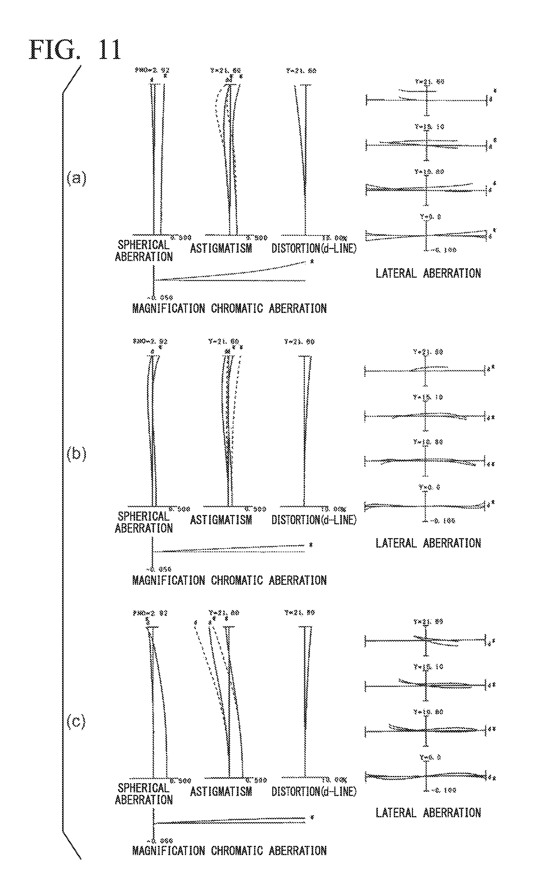
FIG. 11 shows graphs illustrating various aberrations of the variable magnification optical system according to Example 4 upon focusing on infinity, wherein parts (a), (b), and (c) are in the wide-angle end state, the intermediate focal length state, and the telephoto end state, respectively.
FIG. 12 shows graphs illustrating lateral aberrations of the variable magnification optical system according to Example 4 after image blur correction was performed upon focusing on infinity, wherein parts (a), (b), and (c) are in the wide-angle end state, the intermediate focal length state, and the telephoto end state, respectively.
FIG. 13 is a cross-sectional view of a variable magnification optical system according to Example 5, wherein parts (W), (M), and (T) are in a wide-angle end state, an intermediate focal length state, and a telephoto end state, respectively.
FIG. 14 shows graphs illustrating various aberrations of the variable magnification optical system according to Example 5 upon focusing on infinity, wherein parts (a), (b), and (c) are in the wide-angle end state, the intermediate focal length state, and the telephoto end state, respectively.
FIG. 15 shows graphs illustrating lateral aberrations of the variable magnification optical system according to Example 5 after image blur correction was performed upon focusing on infinity, wherein parts (a), (b), and (c) are in the wide-angle end state, the intermediate focal length state, and the telephoto end state, respectively.
FIG. 16 is a cross-sectional view of a variable magnification optical system according to Example 6, wherein parts (W), (M), and (T) are in a wide-angle end state, an intermediate focal length state, and a telephoto end state, respectively.
FIG. 17 shows graphs illustrating various aberrations of the variable magnification optical system according to Example 6 upon focusing on infinity, wherein parts (a), (b), and (c) are in the wide-angle end state, the intermediate focal length state, and the telephoto end state, respectively.
FIG. 18 shows graphs illustrating lateral aberrations of the variable magnification optical system according to Example 6 after image blur correction was performed upon focusing on infinity, wherein parts (a), (b), and (c) are in the wide-angle end state, the intermediate focal length state, and the telephoto end state, respectively.
FIG. 19 is a cross-sectional view of a variable magnification optical system according to Example 7, wherein parts (W), (M), and (T) are in a wide-angle end state, an intermediate focal length state, and a telephoto end state, respectively.
FIG. 20 shows graphs illustrating various aberrations of the variable magnification optical system according to Example 7 upon focusing on infinity, wherein parts (a), (b), and (c) are in the wide-angle end state, the intermediate focal length state, and the telephoto end state, respectively.
FIG. 21 shows graphs illustrating lateral aberrations of the variable magnification optical system according to Example 7 after image blur correction was performed upon focusing on infinity, wherein parts (a), (b), and (c) are in the wide-angle end state, the intermediate focal length state, and the telephoto end state, respectively.
FIG. 22 is a cross-sectional view of a variable magnification optical system according to Example 8, wherein parts (W), (M), and (T) are in a wide-angle end state, an intermediate focal length state, and a telephoto end state, respectively.
FIG. 23 shows graphs illustrating various aberrations of the variable magnification optical system according to Example 8 upon focusing on infinity, wherein parts (a), (b), and (c) are in the wide-angle end state, the intermediate focal length state, and the telephoto end state, respectively.
FIG. 24 shows graphs illustrating lateral aberrations of the variable magnification optical system according to Example 8 after image blur correction was performed upon focusing on infinity, wherein parts (a), (b), and (c) are in the wide-angle end state, the intermediate focal length state, and the telephoto end state, respectively.
FIG. 25 is a cross-sectional view of a variable magnification optical system according to Example 9, wherein parts (W), (M), and (T) are in a wide-angle end state, an intermediate focal length state, and a telephoto end state, respectively.
FIG. 26 shows graphs illustrating various aberrations of the variable magnification optical system according to Example 9 upon focusing on infinity, wherein parts (a), (b), and (c) are in the wide-angle end state, the intermediate focal length state, and the telephoto end state, respectively.
FIG. 27 shows graphs illustrating lateral aberrations of the variable magnification optical system according to Example 9 after image blur correction was performed upon focusing on infinity, wherein parts (a), (b), and (c) are in the wide-angle end state, the intermediate focal length state, and the telephoto end state, respectively.
FIG. 28 is a cross-sectional view of a variable magnification optical system according to Example 10, wherein parts (W), (M), and (T) are in a wide-angle end state, an intermediate focal length state, and a telephoto end state, respectively.
FIG. 29 shows graphs illustrating various aberrations of the variable magnification optical system according to Example 10 upon focusing on infinity, wherein parts (a), (b), and (c) are in the wide-angle end state, the intermediate focal length state, and the telephoto end state, respectively.
FIG. 30 shows graphs illustrating lateral aberrations of the variable magnification optical system according to Example 10 after image blur correction was performed upon focusing on infinity, wherein parts (a), (b), and (c) are in the wide-angle end state, the intermediate focal length state, and the telephoto end state, respectively.
FIG. 31 is a cross-sectional views of a variable magnification optical system according to Example 11, wherein parts (W), (M), and (T) are in a wide-angle end state, an intermediate focal length state, and a telephoto end state, respectively.
FIG. 32 shows graphs illustrating various aberrations of the variable magnification optical system according to Example 11 upon focusing on infinity, wherein parts (a), (b), and (c) are in the wide-angle end state, the intermediate focal length state, and the telephoto end state, respectively.
FIG. 33 shows graphs illustrating lateral aberrations of the variable magnification optical system according to Example 11 after image blur correction was performed upon focusing on infinity, wherein parts (a), (b), and (c) are in the wide-angle end state, the intermediate focal length state, and the telephoto end state, respectively.
FIG. 34 is a cross-sectional view of a variable magnification optical system according to Example 12, wherein parts (W), (M), and (T) are in a wide-angle end state, an intermediate focal length state, and a telephoto end state, respectively.
FIG. 35 shows graphs illustrating various aberrations of the variable magnification optical system according to Example 12 upon focusing on infinity, wherein parts (a), (b), and (c) are in the wide-angle end state, the intermediate focal length state, and the telephoto end state, respectively.
FIG. 36 shows graphs illustrating lateral aberrations of the variable magnification optical system according to Example 12 after image blur correction was performed upon focusing on infinity, wherein parts (a), (b), and (c) are in the wide-angle end state, the intermediate focal length state, and the telephoto end state, respectively.
FIG. 37 is a diagram illustrating an example of a configuration of a camera having a variable magnification optical system mounted thereon.
FIG. 38 is a diagram illustrating an outline of an example of a method for manufacturing a variable magnification optical system.
DESCRIPTION OF EMBODIMENTS
An embodiment will now be described with reference to the drawings. FIG. 1 illustrates an example of a configuration of a variable magnification optical system (variable power optical system) ZL. In other examples, the number of lens groups, a lens configuration of each lens group, and the like can be changed appropriately.
In an embodiment, a variable magnification optical system ZL includes a first lens group G1 having a negative refractive power, a second lens group G2 having a positive refractive power, and an intermediate group (an n-th lens group) disposed closer to an image side than the second lens group G2, the system including a vibration-reduction lens group VR disposed closer to the image side than the intermediate group Gn and configured to be moveable so as to have component in a direction orthogonal to an optical axis, the system performing varying magnification (varying power) by changing at least the distance between the first lens group G1 and the second lens group G2 and the distance between the second lens group G2 and the intermediate group Gn. In an example, the position of the intermediate group Gn in the direction orthogonal to the optical axis is immovable, and the intermediate group Gn has a negative refractive power.
In Example 1 illustrated in FIG. 1, the intermediate group Gn of which the position in the direction orthogonal to the optical axis is immovable and which has negative refractive power and the vibration-reduction lens group VR disposed at an image-side of the intermediate group correspond to a 31st lens group G31 and a 32nd lens group G32, respectively. In Examples 2, 3, 5, and 7 to 11 to be described later, the intermediate group Gn and the vibration-reduction lens group VR disposed at an image-side of the intermediate group correspond to a 31st lens group G31 and a 32nd lens group G32, respectively. In Examples 4, 6, and 12, the intermediate group Gn and the vibration-reduction lens group VR disposed at an image-side of the intermediate group correspond to a fourth lens group G4 and a fifth lens group G5.
The vibration-reduction lens group VR preferably has negative refractive power.
As described above, the variable magnification optical system ZL has lens groups having negative, positive, negative, and positive refractive power or negative, positive, negative, positive, and positive refractive power and changes at least the distances between these lens groups. Therefore, it is possible to implement a variable magnification optical system having a wide angle of view. Moreover, the variable magnification optical system ZL includes the intermediate group Gn having a negative refractive power and the vibration-reduction lens group VR (having a negative refractive power) disposed at an image-side of the intermediate group, and the vibration-reduction lens group VR is moved so as to have a component in the direction orthogonal to the optical axis to perform image blur correction. Therefore, it is possible to suppress the occurrence of eccentric coma aberration (decentering coma aberration) and one-sided blur during image blur correction and to obtain satisfactory imaging performance.
The variable magnification optical system ZL satisfies Conditional Expression (1) below. 1.000<f(1.about.Gn)t/ft<100.000 (1)
where
f(1.about.Gn)t: a composite focal length from the first lens group G1 to the intermediate group Gn in a telephoto end state
ft: a focal length of the entire system in the telephoto end state
Conditional Expression (1) is a conditional expression for restoring incident light converged by the first lens group G1 and the second lens group G2 to light (approximately afocal light) substantially parallel to the optical axis using the intermediate group Gn and guiding the light toward the vibration-reduction lens group VR to thereby improve a vibration-reduction performance. When Conditional Expression (1) is satisfied, it is possible to secure a bright F-value of approximately F2.8 to F3.5 and to correct aberrations including spherical aberration satisfactorily.
If the imaging magnification exceeds the upper limit value of Conditional Expression (1), the power of the intermediate group Gn is too large, the correction of aberrations such as spherical aberration by the intermediate group Gn is insufficient, and it is difficult to obtain a variable magnification ratio (variable power ratio) of approximately 3 or higher
In order to obtain the effect reliably, it is preferable that the upper limit value of Conditional Expression (1) is set to 50.000. In order to obtain the effect more reliably, it is preferable that the upper limit value of Conditional Expression (1) is set to 25.000.
If the imaging magnification is smaller than the lower limit value of Conditional Expression (1), strong convergent light enters the vibration-reduction lens group VR, and it is difficult to suppress the occurrence of eccentric coma aberration in the telephoto end state during image blur correction and the occurrence of one-sided blur in the wide-angle end state. As a result, it is difficult to set the F-value to be as bright as approximately F2.8 to F3.5. In some cases, the occurrence of spherical aberration becomes severe, and it may be difficult to obtain a satisfactory imaging performance.
In order to obtain the effect reliably, it is preferable that the lower limit value of Conditional Expression (1) is set to 1.500. In order to obtain the effect more reliably, it is preferable that the lower limit value of Conditional Expression (1) is set to 2.000.
Preferably, the variable magnification optical system ZL satisfies Conditional Expression (2) below. 1.360<-f(Gn.about.G(VR))w/fw<5.000 (2)
where
f(Gn.about.G(VR))w: a composite focal length from the intermediate group Gn to the vibration-reduction lens group VR in the wide-angle end state
fw: a focal length of the entire system in the wide-angle end state
Conditional Expression (2) is a conditional expression for obtaining a variable magnification ratio of approximately 3 and a satisfactory optical performance by appropriately setting the composite focal length in the wide-angle end state, of the intermediate group Gn and the vibration-reduction lens group VR. When Conditional Expression (2) is satisfied, it is possible to secure a bright F-value of approximately F2.8 to F3.5 and to correct aberrations including spherical aberration satisfactorily.
If the focal length ratio exceeds the upper limit value of Conditional Expression (2), a composite refractive power of the intermediate group Gn and the vibration-reduction lens group VR becomes too small and it is difficult to secure a variable magnification ratio of approximately 3 in the entire system. As a result, it is necessary for the second lens group G2 or other groups to perform varying magnification, and consequently, correction of spherical aberration or coma aberration is insufficient.
In order to obtain the effect reliably, it is preferable that the upper limit value of Conditional Expression (2) is set to 4.000. In order to obtain the effect more reliably, it is preferable that the upper limit value of Conditional Expression (2) is set to 3.000.
If the focal length ratio is smaller than the lower limit value of Conditional Expression (2), the composite refractive power of the intermediate group Gn and the vibration-reduction lens group VR is too large and it is difficult to correct spherical aberration and coma aberration. As a result, it is difficult to obtain a satisfactory imaging performance while obtaining a bright F-value of approximately F2.8 to F3.5.
In order to obtain the effect reliably, it is preferable that the lower limit value of Conditional Expression (2) is set to 1.400. In order to obtain the effect more reliably, it is preferable that the lower limit value of Conditional Expression (2) is set to 1.450.
Preferably, the variable magnification optical system ZL includes an image-side lens group RP having the strongest positive refractive power among the lens groups having a positive refractive power disposed closer to the image side than the vibration-reduction lens group VR, the distance between the image-side lens group RP and the vibration-reduction lens group VR changes upon varying magnification, and preferably, Conditional Expression (3) below is satisfied. 0.400<f(RP)/f(FP)<2.000 (3)
where f(RP): a focal length of the image-side lens group RP f(FP): a composite focal length in the wide-angle end state, of lenses disposed closer to the image plane side than the first lens group G1 and disposed closer to the object side than the intermediate group Gn
Conditional Expression (3) is a conditional expression for obtaining a variable magnification ratio of approximately 3 and a satisfactory optical performance by appropriately setting the refractive power of the image-side lens group RP. When Conditional Expression (3) is satisfied, it is possible to secure a bright F-value of approximately F2.8 to F3.5 and to correct aberrations including spherical aberration satisfactorily.
When the focal length ratio exceeds the upper limit value of Conditional Expression (3), varying magnification by the image-side lens group RP is insufficient and it is difficult to secure a variable magnification ratio of approximately 3 in the entire system. As a result, it is necessary to cause the second lens group G2 or other groups to perform varying magnification, and consequently, correction of spherical aberration or coma aberration is insufficient.
In order to obtain the effect reliably, it is preferable that the upper limit value of Conditional Expression (3) is set to 1.800. In order to obtain the effect more reliably, it is preferable that the upper limit value of Conditional Expression (3) is set to 1.700.
If the focal length ratio is smaller than the lower limit value of Conditional Expression (3), the refractive power of the image-side lens group RP is too large and it is difficult to correct spherical aberration and coma aberration. As a result, it is difficult to obtain a satisfactory imaging performance while obtaining a bright F-value of approximately F2.8 to F3.5.
In order to obtain the effect reliably, it is preferable that the lower limit value of Conditional Expression (3) is set to 0.500. In order to obtain the effect more reliably, it is preferable that the lower limit value of Conditional Expression (3) is set to 0.600.
In the variable magnification optical system ZL, it is preferable that the intermediate group Gn has one or more positive lens components and one or more negative lens components.
The "lens component" refers to a single lens or a cemented lens.
Due to this configuration, it is possible to satisfactorily correct the spherical aberration and the coma aberration using the intermediate group Gn and to improve a vibration-reduction performance. When the intermediate group Gn includes any one of the lens components, correction of spherical aberration and coma aberration by the intermediate group Gn is insufficient, and it is necessary to cause the vibration-reduction lens group VR to correct these aberrations. As a result, the occurrence of eccentric coma aberration or one-sided blur occurring during image blur correction is greater, and it is difficult to maintain a satisfactory imaging performance during image blur correction.
In order to obtain the effect reliably, it is more preferable that the intermediate group Gn has at least two negative lens components and one or more positive lens components.
In the variable magnification optical system ZL, it is preferable that the second lens group G2 has at least four lens components.
Due to this configuration, it is possible to satisfactorily correct spherical aberration and coma aberration using the second lens group G2 and to improve a vibration-reduction performance. When the second lens group G2 has three or fewer lens components, since correction of spherical aberration and coma aberration by the second lens group G2 is insufficient, it is necessary to cause the intermediate group Gn to correct these aberrations. As a result, the occurrence of eccentric coma aberration or one-sided blur occurring during image blur correction is greater, and it is difficult to maintain a satisfactory imaging performance during image blur correction.
In order to obtain the effect reliably, it is preferable that the second lens group G2 has five or more lens components.
In the variable magnification optical system ZL, it is preferable that the second lens group G2 is constituted by, in order from the object, a 21st lens group G21 having a positive refractive power and a 22nd lens group G22 having a positive refractive power, and preferably, focusing from an object at infinity to an object at a close distance is performed by moving the 21st lens group G21 to the image side as a focusing lens group.
Due to this configuration, it is possible to decrease the size and the weight of the lens group that moves upon focusing and to decrease the size of an entire lens system and accelerate the focusing speed during autofocus.
The variable magnification optical system ZL preferably satisfies Conditional Expression (4) below. 10.00.degree.<.omega.t<30.00.degree. (4)
where
.omega.t: a half-angle of view in the telephoto end state
Conditional Expression (4) is a condition that determines the value of a half-angle of view in the telephoto end state. When Conditional Expression (4) is satisfied, it is possible to obtain a desired angle of view and to satisfactorily correct coma aberration, distortion, and a curvature of field.
In order to obtain the effect reliably, it is preferable that the upper limit value of Conditional Expression (4) is set to 27.00.degree.. In order to obtain the effect more reliably, it is preferable that the upper limit value of Conditional Expression (4) is set to 24.00.degree..
In order to obtain the effect reliably, it is preferable that the lower limit value of Conditional Expression (4) is set to 11.00.degree.. In order to obtain the effect more reliably, it is preferable that the lower limit value of Conditional Expression (4) is set to 12.00.degree..
The variable magnification optical system ZL preferably satisfies Conditional Expression (5) below. 30.00.degree.<.omega.w<50.00.degree. (5)
where
.omega.w: a half-angle of view in the wide-angle end state
Conditional Expression (5) is a condition that specifies the value of a half-angle of view in the wide-angle end state. When Conditional Expression (5) is satisfied, it is possible to obtain a desired angle of view and to satisfactorily correct coma aberration, distortion, and a curvature of field.
In order to obtain the effect reliably, it is preferable that the upper limit value of Conditional Expression (5) is set to 48.00.degree.. In order to obtain the effect more reliably, it is preferable that the upper limit value of Conditional Expression (5) is set to 45.00.degree..
In order to obtain the effect reliably, it is preferable that the lower limit value of Conditional Expression (5) is set to 32.00.degree.. In order to obtain the effect more reliably, it is preferable that the lower limit value of Conditional Expression (5) is set to 34.00.degree..
In the variable magnification optical system ZL, the distance between the 21st lens group G21 and the 22nd lens group G22 may be fixed or variable upon varying magnification.
In the variable magnification optical system ZL, the distance between the intermediate group Gn and the vibration-reduction lens group VR may be fixed or variable upon varying magnification. When the distance is fixed, it is preferable that the composite refractive power of the intermediate group Gn and the vibration-reduction lens group VR is negative.
In the variable magnification optical system ZL, it is preferable that an optical system constituted by lenses disposed closer to the image side than the vibration-reduction lens group VR has a positive refractive power.
The variable magnification optical system ZL preferably has at least one lens group having a positive refractive power on a side closer to the image side than the vibration-reduction lens group VR.
The variable magnification optical system ZL preferably has an aperture stop between the second lens group G2 and the intermediate group Gn.
In this way, it is possible to implement a variable magnification optical system ZL which has a bright F-value and a wide angle of view and in which aberrations are corrected satisfactorily.
Next, a camera (an optical apparatus) having the above-described variable magnification optical system ZL will be described with reference to the drawings. FIG. 37 illustrates an example of a configuration of a camera having a variable magnification optical system mounted thereon.
As illustrated in FIG. 37, a camera 1 is an interchangeable lens camera (so-called a mirrorless camera) having the above-described variable magnification optical system ZL as an image capturing lens 2. In this camera 1, light from an object (a subject) which is not illustrated is collected by the image capturing lens 2 and forms a subject image on an image plane of the imaging unit 3 via an optical low-pass filter (OLPF) which is not illustrated. The subject image is photoelectrically converted by a photoelectric conversion element provided in the imaging unit 3, whereby the image of the object is generated. This image is displayed on an electronic viewfinder (EVF) 4 provided in the camera 1. In this way, a photographer can view the subject via the EVF 4. Moreover, when a release button (not illustrated) is pressed by the photographer, the image of the subject generated by the imaging unit 3 is stored in a memory (not illustrated). In this way, the photographer can capture the image of the subject using the camera 1.
As can be understood from respective examples to be described later, the variable magnification optical system ZL mounted on the camera 1 as the image capturing lens 2 has a bright F-value and a wide angle of view and has a satisfactory optical performance such that aberrations are corrected satisfactorily due to its characteristic lens configuration. Therefore, according to the camera 1, it is possible to implement an optical apparatus which has a bright F-value and a wide angle of view and has a satisfactory optical performance such that aberrations are corrected satisfactorily.
Although a mirrorless camera has been described as an example of the camera 1, the camera is not limited to this. For example, the same effect as the camera 1 can be obtained even when the above-described variable magnification optical system ZL is mounted on a single-lens reflex camera which has a quick return mirror on a camera body and views a subject using a finder optical system.
Next, an example of a method for manufacturing the above-described variable magnification optical system ZL will be described. FIG. 38 illustrate an example of a method for manufacturing the variable magnification optical system ZL.
First, respective lenses are arranged in a lens barrel so as to include a first lens group G1 having a negative refractive power and a second lens group G2 having a positive refractive power (step ST10). Respective lenses are arranged so as to have an intermediate group Gn disposed closer to an image side than the second lens group G2 (step ST20). Respective lenses are arranged so as to have a vibration-reduction lens group VR disposed closer to the image side than the intermediate group Gn and configured to be movable so as to have a component in the direction orthogonal to the optical axis (step ST30). Respective lenses are arranged so that varying magnification is performed by changing at least the distance between the first lens group G1 and the second lens group G2 and the distance between the second lens group G2 and the intermediate group Gn (step ST40). The respective lenses are arranged so as to satisfy Conditional Expression (1) below (step ST50). 1.000<f(1.about.Gn)t/ft<100.000 (1)
where
f(1.about.Gn)t: a composite focal length from the first lens group G1 to the intermediate group Gn in a telephoto end state
ft: a focal length of the entire system in the telephoto end state
According to an example of a lens arrangement, as illustrated in FIG. 1, a negative meniscus lens L11 having a concave surface oriented toward an image side, a biconcave lens L12, and a positive meniscus lens L13 having a convex surface oriented toward the object side are arranged, in order from the object, to form the first lens group G1. A biconvex lens L21, a positive meniscus lens L22 having a convex surface oriented toward the object side, a cemented lens including a biconvex lens L23 and a biconcave lens L24, and a biconvex lens L25 are arranged, in order from the object, to form the 21st lens group G21. A biconvex lens L26 is arranged to form the 22nd lens group G22. A biconcave lens L31, a negative meniscus lens L32 having a concave surface oriented toward the object side, and a biconvex lens L33 are arranged, in order from the object, to form the 31st lens group G31. A biconcave lens L34 and a positive meniscus lens L35 having a convex surface oriented toward the object side are arranged, in order from the object, to form the 32nd lens group G32. A biconvex lens L41, a cemented lens including a negative meniscus lens L42 having a concave surface oriented toward the image side and a biconvex lens L43, and a cemented lens including a biconvex lens L44, a biconcave lens L45, and a positive meniscus lens L46 having a convex surface oriented toward the object side are, in order from the object, to form the fourth lens group G4. The respective lens groups prepared in this manner are arranged in the above-described order to manufacture the variable magnification optical system ZL.
According to the above-described manufacturing method, it is possible to manufacture the variable magnification optical system ZL which has a bright F-value and a wide angle of view and in which aberrations are corrected satisfactorily.
EXAMPLES
Hereinafter, respective examples will be described with reference to the drawings.
FIGS. 1, 4, 7, 10, 13, 16, 19, 22, 25, 28, 31, and 34 are cross-sectional views illustrating the configuration and the refractive power allocation of variable magnification optical systems ZL (ZL1 to ZL12) according to respective examples. In the lower part of the cross-sectional views of the variable magnification optical systems ZL1 to ZL12, the moving directions along the optical axis of each lens group upon varying magnification from the wide-angle end state (W) to the telephoto end state (T) via the intermediate focal length state (M) are indicated by arrows. In the upper part of the cross-sectional views of the variable magnification optical systems ZL1 to ZL13, the moving direction of the focusing lens group upon focusing from an object at infinity to an object at a close distance is indicated by an arrow and the state of the vibration-reduction lens group VR when correcting image blur is also illustrated.
Respective reference signs in FIG. 1 associated with Example 1 are used independently in respective examples in order to avoid complication of description due to an increased number of reference sign characters. Therefore, even when components in diagrams associated with other examples are denoted by the same reference signs as used in FIG. 1, these components do not necessarily have the same configuration as those of other examples.
Tables 1 to 12 illustrated below are tables of respective specifications of Examples 1 to 12.
In the respective examples, the d-line (wavelength: 587.562 nm) and the g-line (wavelength: 435.835 nm) are selected as an aberration characteristics calculation target.
In [Lens Specification] in tables, a surface number indicates a sequence number of an optical surface from an object side along a traveling direction of light, R indicates a radius of curvature of each optical surface, D indicates a surface distance which is the distance on the optical axis from each optical surface to the next optical surface (or an image plane), nd indicates a refractive index for the d-line, of a material of an optical member, .nu.d indicates the Abbe number for the d-line, of a material of an optical member, and Aperture stop indicates an aperture stop S. When the radius of curvature is "0.00000," this indicates a flat surface for a lens surface and indicates an aperture or a diaphragm surface for an aperture stop. When the optical surface is an aspherical surface, a mark "*" is assigned to the surface number and a paraxial radius of curvature is shown in the radius of curvature column R.
In [Aspheric Data] in tables, the shape of an aspherical surface shown in [Lens Specification] is expressed by Equation (a) below. X(y) indicates the distance along the optical axis direction from a tangential plane at the vertex of an aspherical surface to a position on the aspherical surface at a height y, R indicates a radius of curvature (a paraxial radius of curvature) of a reference spherical surface, .kappa. indicates a conic constant, and Ai indicates an aspheric coefficient at degree i. "E-n" indicates ".times.10.sup.-n". For example, 1.234E-05=1.234.times.10.sup.-5. An aspheric coefficient A2 at degree 2 is 0 and is not illustrated. X(y)=(y.sup.2/R)/{1+(1-.kappa..times.y.sup.2/R.sup.2).sup.1/2}+A4.times.y- .sup.4+A6.times.y.sup.6+A8.times.y.sup.8+A.sup.10.times.y.sup.10+A12.times- .y.sup.12(a)
In [Various Data] in tables, f indicates a focal length of an entire lens system, FNo indicates the F-number, .omega. indicates a half-angle of view (unit: .degree.), Y indicates the maximum image height, TL indicates the distance from the frontmost lens surface to the last lens surface on the optical axis upon focusing on infinity, BF indicates the distance from the last lens surface to the image plane I on the optical axis upon focusing on infinity, and BF (air-conversion length) indicates the distance (an air-conversion length) from the last lens surface to the image plane I on the optical axis upon focusing on infinity.
In [Variable Distance Data] in tables, DO indicates an axial air distance between an object plane and a lens surface closest to an object, of the first lens group G1, Di indicates a surface distance (i=1, 2, 3, . . . ) between an i-th surface and an (i+1)th surface, and f indicates the focal length of an entire lens system.
In [Lens Group Data] in tables, a starting surface and a focal length of each lens group are illustrated.
In [Focusing Data] in tables, a lens moving distance and an imaging distance upon focusing are illustrated.
In [Conditional Expression Correspondence Values] in tables, values corresponding to Conditional Expressions (1) to (5) are illustrated.
Hereinafter, "mm" is generally used as the unit of the focal length f, the radius of curvature R, the surface distance D, and other lengths and the like described in all specification values unless particularly stated otherwise. However, the unit is not limited to this since an equivalent optical performance is obtained even when the optical system is proportionally expanded or reduced. Moreover, the unit is not limited to "mm" and other appropriate units may be used.
The above description of tables is common to all examples, and description thereof will not be provided below.
Example 1
Example 1 will be described with reference to FIGS. 1 to 3 and Table 1. As illustrated in FIG. 1, a variable magnification optical system ZL (ZL1) according to Example 1 is constituted by, in order from an object, a first lens group G1 having a negative refractive power, a second lens group G2 having a positive refractive power, a third lens group G3 having a negative refractive power, and a fourth lens group G4 having a positive refractive power.
The first lens group G1 is constituted by, in order from the object, a negative meniscus lens L11 having a concave surface oriented toward the image side, a biconcave lens L12, and a positive meniscus lens L13 having a convex surface oriented toward the object side. The negative meniscus lens L11 has an aspherical image-side surface. The biconcave lens L12 is a composite aspherical lens obtained by forming a resin layer formed on a glass surface on the object side into an aspherical surface.
The second lens group G2 is constituted by, in order from the object, a 21st lens group G21 (a focusing lens group) having a positive refractive power and a 22nd lens group G22 having a positive refractive power.
The 21st lens group G21 is constituted by, in order from the object, a biconvex lens L21, a positive meniscus lens L22 having a convex surface oriented toward the object side, a cemented lens including a biconvex lens L23 and a biconcave lens L24, and a biconvex lens L25. The 22nd lens group G22 is constituted by a biconvex lens L26.
The third lens group G3 is constituted by, in order from the object, a 31st lens group G31 (an intermediate group) of which the position in the direction orthogonal to the optical axis is immovable and which has negative refractive power and a 32nd lens group G32 (a vibration-reduction lens group) having a negative refractive power.
The 31st lens group G31 is constituted by, in order from the object, a biconcave lens L31, a negative meniscus lens L32 having a concave surface oriented toward the object side, and a biconvex lens L33. The 32nd lens group G32 is constituted by, in order from the object, a biconcave lens L34 and a positive meniscus lens L35 having a convex surface oriented toward the object side.
The fourth lens group G4 is constituted by, in order from the object, a biconvex lens L41, a cemented lens including a negative meniscus lens L42 having a concave surface oriented toward the image side and a biconvex lens L43, and a cemented lens including a biconvex lens L44, a biconcave lens L45, and a positive meniscus lens L46 having a convex surface oriented toward the object side. The biconvex lens L41 has an aspherical object-side surface. The positive meniscus lens L46 has an aspherical image-side surface.
A first flare-cut diaphragm FC1 and an aperture stop S arranged in that order from the object are disposed between the second lens group G2 and the third lens group G3. A second flare-cut diaphragm FC2 is disposed between the fourth lens group G4 and the image plane I.
Varying magnification from the wide-angle end state to the telephoto end state is performed by moving the first lens group G1 toward the image side and then moving the first lens group G1 toward the object side, moving the second lens group G2 toward the object side, moving the third lens group G3 toward the image side and then moving the same toward the object side, and moving the fourth lens group G4 toward the object side such that the distances between the respective lens groups are changed. The first flare-cut diaphragm FC1, the aperture stop S, and the second flare-cut diaphragm FC2 are immovable upon varying magnification.
Focusing from an object at infinity to an object at a close distance is performed by moving the 21st lens group G21 as a focusing lens group toward the image side.
When image blur occurs, image blur correction (vibration reduction) on the image plane I is performed by moving the 32nd lens group G32 as the vibration-reduction lens group VR so as to have a component in the direction orthogonal to the optical axis. In an image capturing lens in which the focal length of an entire system is f and a vibration reduction coefficient (the ratio of an image moving distance on an imaging plane to a moving distance of a moving lens group during blur correction) is .kappa., in order to correct rotation blur of angle .theta., the vibration-reduction lens group VR (a moving lens group) for image blur correction may be moved in the direction orthogonal to the optical axis by (f.times.tan .theta.)/K.
In Example 1, in the wide-angle end state, since the vibration reduction coefficient is -0.45 and the focal length is 24.80 mm, the moving distance of the vibration-reduction lens group VR for correcting the rotation blur of 0.30.degree. is -0.29 mm. In the intermediate focal length state, since the vibration reduction coefficient is -0.51 and the focal length is 50.01 mm, the moving distance of the vibration-reduction lens group VR for correcting the rotation blur of 0.30.degree. is -0.51 mm. In the telephoto end state, since the vibration reduction coefficient is -0.58 and the focal length is 67.85 mm, the moving distance of the vibration-reduction lens group VR for correcting the rotation blur of 0.30.degree. is -0.61 mm.
Table 1 illustrates the values of respective specifications of Example 1. Surface numbers 1 to 40 in Table 1 correspond to optical surfaces of m1 to m40 illustrated in FIG. 1.
TABLE-US-00001 TABLE 1 [Lens Specification] Surface number R D n(d) .nu.d 1 121.85638 2.900 1.74389 49.5 *2 29.63670 15.360 1.00000 *3 -197.50816 0.200 1.56093 36.6 4 -169.39125 2.100 1.80400 46.6 5 60.51496 0.150 1.00000 6 52.85097 5.600 2.00100 29.1 7 146.47986 D7 1.00000 8 148.41161 3.000 1.59349 67.0 9 -517.10678 0.100 1.00000 10 49.87002 3.500 1.59349 67.0 11 157.35190 4.762 1.00000 12 87.49334 4.800 1.59349 67.0 13 -132.22400 1.500 1.90366 31.3 14 45.76622 1.640 1.00000 15 78.93526 4.450 1.77250 49.6 16 -176.75459 D16 1.00000 17 57.14809 5.300 1.81600 46.6 18 -583.40702 D18 1.00000 19 0.00000 1.200 1.00000 20 (Aperture stop) D20 1.00000 21 -141.85186 1.200 1.80400 46.6 22 33.20059 4.360 1.00000 23 -33.72704 1.200 1.60300 65.4 24 -60.09530 0.100 1.00000 25 65.48868 3.150 1.84666 23.8 26 -127.25009 D26 1.00000 27 -119.24441 1.100 1.59349 67.0 28 67.70394 1.150 1.00000 29 62.36800 2.100 1.80518 25.5 30 107.42000 D30 1.00000 *31 119.87584 4.700 1.55332 71.7 32 -115.00129 0.100 1.00000 33 71.95116 1.400 1.83481 42.7 34 38.48800 6.800 1.59319 67.9 35 -237.01429 0.280 1.00000 36 43.00799 9.500 1.49782 82.6 37 -42.99900 1.400 1.80518 25.5 38 98.94100 4.600 1.69350 53.3 *39 462.40647 D39 1.00000 40 0.00000 D40 1.00000 [Aspheric Data] 2nd surface .kappa. = 0.00000e+00 A4 = 2.21510e-06 A6 = 2.57690e-09 A8 = -6.01500e-12 A10 = 1.09200e-14 A12 = -7.29000e-18 3rd surface .kappa. = 1.00000e+00 A4 = -3.83430e-07 A6 = 7.93340e-10 A8 = -3.53630e-12 A10 = 5.08120e-15 A12 = -3.43370e-18 31st surface .kappa. = 1.00000e+00 A4 = 4.80890e-06 A6 = 5.06980e-10 A8 = -2.73140e-12 A10 = -7.78150e-16 A12 = 0.00000e+00 39th surface .kappa. = 1.00000e+00 A4 = 7.56540e-06 A6 = -9.88600e-10 A8 = 5.61740e-12 A10 = -8.07750e-15 A12 = 0.00000e+00 [Various Data] W M T f 24.80 50.01 67.85 FNo 2.92 2.92 2.92 .omega. 42.5 22.7 17.2 Y 21.60 21.60 21.60 TL 220.251 198.419 200.827 BF 41.035 48.522 55.686 BF (air-conversion length) 41.035 48.522 55.686 [Variable Distance Data] Focusing on infinity W M T D0 .infin. .infin. .infin. Magnification -- -- -- f 24.80 50.01 67.85 D7 48.945 10.930 1.902 D16 7.735 7.735 7.735 D18 1.802 17.931 29.439 D20 2.088 4.668 3.620 D26 1.250 1.250 1.250 D30 17.692 7.680 1.492 D39 2.530 10.000 17.180 D40 38.505 38.522 38.506 [Lens Group Data] Lens group Starting surface Focal length 1st lens group 1 -38.47 2nd lens group 8 42.49 21st lens group 8 78.58 22nd lens group 17 64.02 3rd lens group 21 -39.26 31st lens group 21 -65.76 32nd lens group 27 -121.07 4th lens group 31 48.95 [Focusing Data] W M T Lens moving 6.735 6.735 6.735 distance Imaging distance 0.4183 0.3810 0.3966 (m) [Conditional Expression Correspondence Values] Conditional Expression (1) f(1~Gn)t/ft = 10.118 Conditional Expression (2) -f(Gn~G(VR))w/fw = 1.583 Conditional Expression (3) f(RP)/f(FP) = 1.152 Conditional Expression (4) .omega.t = 17.2 Conditional Expression (5) .omega.w = 42.5
It can be understood from Table 1 that the variable magnification optical system ZL1 according to Example 1 satisfies Conditional Expressions (1) to (5).
FIG. 2 shows graphs illustrating various aberrations (spherical aberration, astigmatism, distortion, magnification chromatic aberration (lateral chromatic aberration), and lateral aberration) upon focusing on infinity, of the variable magnification optical system ZL1 according to Example 1, in which part (a) illustrates the wide-angle end state, part (b) illustrates the intermediate focal length state, and part (c) illustrates the telephoto end state. FIG. 3 shows graphs illustrating lateral aberration of the variable magnification optical system ZL1 according to Example 1 when image blur correction is performed upon focusing on infinity, in which part (a) illustrates the wide-angle end state, part (b) illustrates the intermediate focal length state, and part (c) illustrates the telephoto end state. In this example, the optical performance during vibration reduction is illustrated as a lateral aberration graph corresponding to an image height of .+-.15.10 about the image height y=0.0 as illustrated in FIG. 3.
In the graphs illustrating respective aberrations, FNO indicates the F-number and Y indicates an image height. d indicates aberration at the d-line and g indicates aberration at the g-line. Moreover, aberrations without these characters indicate aberrations at the d-line. In the graphs illustrating the spherical aberration upon focusing on infinity, the F-number values corresponding to the maximum aperture are illustrated. In the graphs illustrating the astigmatism, a solid line indicates the sagittal image plane and a broken line indicates the meridional image plane. The same reference symbols as in this example are used in the aberration graphs of respective examples to be described later.
As is obvious from respective aberration graphs, it can be understood that the variable magnification optical system ZL1 according to Example 1 has a satisfactory optical performance such that aberrations are satisfactorily corrected in states ranging from the wide-angle end state to the telephoto end state. Moreover, it can be understood that the variable magnification optical system ZL1 has an excellent imaging performance upon image blur correction.
Example 2
Example 2 will be described with reference to FIGS. 4 to 6 and Table 2. As illustrated in FIG. 4, a variable magnification optical system ZL (ZL2) according to Example 2 is constituted by, in order from an object, a first lens group G1 having a negative refractive power, a second lens group G2 having a positive refractive power, a third lens group G3 having a negative refractive power, and a fourth lens group G4 having a positive refractive power.
The first lens group G1 is constituted by, in order from the object, a negative meniscus lens L11 having a concave surface oriented toward the image side, a biconcave lens L12, and a positive meniscus lens L13 having a convex surface oriented toward the object side. The negative meniscus lens L11 has an aspherical image-side surface. The biconcave lens L12 is a composite aspherical lens obtained by forming a resin layer formed on a glass surface on the object side into an aspherical surface.
The second lens group G2 is constituted by, in order from the object, a 21st lens group G21 (a focusing lens group) having a positive refractive power and a 22nd lens group G22 having a positive refractive power.
The 21st lens group G21 is constituted by, in order from the object, a biconvex lens L21, a positive meniscus lens L22 having a convex surface oriented toward the object side, a cemented lens including a biconvex lens L23 and a biconcave lens L24, and a biconvex lens L25. The 22nd lens group G22 is constituted by a biconvex lens L26.
The third lens group G3 is constituted by, in order from the object, a 31st lens group G31 (an intermediate group) of which the position in the direction orthogonal to the optical axis is immovable and which has negative refractive power and a 32nd lens group G32 (a vibration-reduction lens group) having a negative refractive power.
The 31st lens group G31 is constituted by, in order from the object, a biconcave lens L31, a negative meniscus lens L32 having a concave surface oriented toward the object side, and a biconvex lens L33. The 32nd lens group G32 is constituted by, in order from the object, a biconcave lens L34 and a positive meniscus lens L35 having a convex surface oriented toward the object side. The biconcave lens L34 has an aspherical object-side surface.
The fourth lens group G4 is constituted by, in order from the object, a biconvex lens L41, a cemented lens including a negative meniscus lens L42 having a concave surface oriented toward the image side and a biconvex lens L43, and a cemented lens including a biconvex lens L44, a biconcave lens L45, and a positive meniscus lens L46 having a convex surface oriented toward the object side. The biconvex lens L41 has an aspherical object-side surface. The positive meniscus lens L46 has an aspherical image-side surface.
An aperture stop S is disposed between the second lens group G2 and the third lens group G3. A flare-cut diaphragm FC is disposed between the fourth lens group G4 and the image plane I.
Varying magnification from the wide-angle end state to the telephoto end state is performed by moving the first lens group G1 toward the image side and then moving the first lens group G1 toward the object side, moving the second lens group G2 toward the object side, moving the third lens group G3 toward the image side and then moving the same toward the object side, and moving the fourth lens group G4 toward the object side such that the distances between the respective lens groups are changed. The aperture stop S and the flare-cut diaphragm FC are immovable upon varying magnification.
Focusing from an object at infinity to an object at a close distance is performed by moving the 21st lens group G21 as a focusing lens group toward the image side.
When image blur occurs, image blur correction (vibration reduction) on the image plane I is performed by moving the 32nd lens group G32 as the vibration-reduction lens group VR so as to have a component in the direction orthogonal to the optical axis. In an image capturing lens in which the focal length of an entire system is f and a vibration reduction coefficient (the ratio of an image moving distance on an imaging plane to a moving distance of a moving lens group during blur correction) is K, in order to correct rotation blur of angle .theta., the vibration-reduction lens group VR (a moving lens group) for image blur correction may be moved in the direction orthogonal to the optical axis by (f.times.tan .theta.)/K.
In Example 2, in the wide-angle end state, since the vibration reduction coefficient is -0.44 and the focal length is 24.80 mm, the moving distance of the vibration-reduction lens group VR for correcting the rotation blur of 0.30.degree. is -0.30 mm. In the intermediate focal length state, since the vibration reduction coefficient is -0.50 and the focal length is 47.76 mm, the moving distance of the vibration-reduction lens group VR for correcting the rotation blur of 0.30.degree. is -0.50 mm. In the telephoto end state, since the vibration reduction coefficient is -0.58 and the focal length is 67.85 mm, the moving distance of the vibration-reduction lens group VR for correcting the rotation blur of 0.30.degree. is -0.62 mm.
Table 2 illustrates the values of respective specifications of Example 2. Surface numbers 1 to 39 in Table 2 correspond to optical surfaces of m1 to m39 illustrated in FIG. 4.
TABLE-US-00002 TABLE 2 [Lens Specification] Surface number R D n(d) .nu.d 1 123.86834 2.900 1.74389 49.5 *2 29.53373 15.066 1.00000 *3 -163.51331 0.300 1.56093 36.6 4 -139.86223 2.100 1.80400 46.6 5 65.45825 0.150 1.00000 6 56.53091 5.625 2.00100 29.1 7 182.99126 D7 1.00000 8 143.07855 3.200 1.59349 67.0 9 -394.38588 0.200 1.00000 10 55.12400 3.500 1.59349 67.0 11 197.46867 3.900 1.00000 12 77.75166 4.842 1.59349 67.0 13 -158.02225 1.500 1.90366 31.3 14 46.02834 1.844 1.00000 15 83.85157 3.848 1.77250 49.6 16 -277.24360 D16 1.00000 17 59.19194 5.400 1.80400 46.6 18 -354.91781 D18 1.00000 19 (Aperture stop) D19 1.00000 20 -140.00000 1.178 1.77250 49.6 21 33.57372 4.337 1.00000 22 -36.69329 1.200 1.59349 67.0 23 -63.63544 0.100 1.00000 24 61.90037 3.102 1.84666 23.8 25 -187.23382 D25 1.00000 *26 -120.15188 1.100 1.61000 65.0 27 78.56667 0.966 1.00000 28 66.22584 1.921 1.80518 25.5 29 108.00000 D29 1.00000 *30 96.36461 5.000 1.55332 71.7 31 -132.37171 0.200 1.00000 32 103.35532 1.300 1.80518 25.5 33 49.66548 6.742 1.59319 67.9 34 -101.36549 0.188 1.00000 35 55.76221 9.450 1.49782 82.6 36 -36.89155 1.400 1.75000 31.4 37 97.48202 4.003 1.69350 53.2 *38 442.81061 D38 1.00000 39 0.00000 D39 1.00000 [Aspheric Data] Surface .kappa. A4 A6 A8 A10 2 1.48700e-01 1.33488e-06 1.45328e-09 -6.97898e-13 5.22062e-16 3 4.31460e+00 -4.66997e-07 4.80176e-10 -1.05569e-12 3.62706e-16 26 -2.40000e+01 -1.76198e-06 1.30497e-09 0.00000e+00 0.00000e+00 30 3.97310e+00 3.04836e-06 -6.62447e-10 0.00000e+00 0.00000e+00 38 3.71000e+02 4.89412e-06 1.67774e-10 0.00000e+00 0.00000e+00 [Various Data] W M T f 24.80 47.76 67.85 FNo 2.92 2.92 2.92 .omega. 42.5 23.7 17.2 Y 21.60 21.60 21.60 TL 219.362 198.056 201.131 BF 41.459 48.894 57.632 BF (air-conversion length) 41.459 48.894 57.632 [Variable Distance Data] Focusing on infinity W M T D0 .infin. .infin. .infin. Magnification -- -- -- f 24.80 47.76 67.85 D7 48.978 12.578 1.835 D16 7.750 7.750 7.750 D18 3.000 18.144 31.911 D19 2.000 4.200 2.500 D25 1.440 1.440 1.440 D29 18.172 8.487 1.500 D38 1.139 8.574 17.251 D39 40.319 40.320 40.381 [Lens Group Data] Lens group Starting surface Focal length 1st lens group 1 -38.77 2nd lens group 8 42.97 21st lens group 8 81.61 22nd lens group 17 63.47 3rd lens group 20 -40.68 31st lens group 20 -68.40 32nd lens group 26 -123.54 4th lens group 30 49.36 [Focusing Data] W M T Lens moving 6.75 6.75 6.75 distance Imaging distance 0.4124 0.3853 0.4059 (m) [Conditional Expression Correspondence Values] Conditional Expression (1) f(1~Gn)t/ft = 12.007 Conditional Expression (2) -f(Gn~G(VR))w/fw = 1.640 Conditional Expression (3) f(RP)/f(FP) = 1.149 Conditional Expression (4) .omega.t = 17.2 Conditional Expression (5) .omega.w = 42.5
It is understood from Table 2 that the variable magnification optical system ZL2 according to Example 2 satisfies Conditional Expressions (1) to (5).
FIG. 5 shows graphs illustrating various aberrations (spherical aberration, astigmatism, distortion, magnification chromatic aberration, and lateral aberration) upon focusing on infinity, of the variable magnification optical system ZL2 according to Example 2, in which part (a) illustrates the wide-angle end state, part (b) illustrates the intermediate focal length state, and part (c) illustrates the telephoto end state. FIG. 6 shows graphs illustrating lateral aberration of the variable magnification optical system ZL2 according to Example 2 when image blur correction is performed upon focusing on infinity, in which part (a) illustrates the wide-angle end state, part (b) illustrates the intermediate focal length state, and part (c) illustrates the telephoto end state. In this example, the optical performance during vibration reduction is illustrated as a lateral aberration graph corresponding to an image height of .+-.15.10 about the image height y=0.0 as illustrated in FIG. 6.
As is obvious from respective aberration graphs, it is understood that the variable magnification optical system ZL2 according to Example 2 has a satisfactory optical performance such that aberrations are satisfactorily corrected in states ranging from the wide-angle end state to the telephoto end state. Moreover, it is understood that the variable magnification optical system ZL2 has an excellent imaging performance upon image blur correction.
Example 3
Example 3 will be described with reference to FIGS. 7 to 9 and Table 3. As illustrated in FIG. 7, a variable magnification optical system ZL (ZL3) according to Example 3 is constituted by, in order from an object, a first lens group G1 having a negative refractive power, a second lens group G2 having a positive refractive power, a third lens group G3 having a negative refractive power, a fourth lens group G4 having a positive refractive power, and a fifth lens group G5 having a positive refractive power.
The first lens group G1 is constituted by, in order from the object, a negative meniscus lens L11 having a concave surface oriented toward the image side, a biconcave lens L12, and a positive meniscus lens L13 having a convex surface oriented toward the object side. The negative meniscus lens L11 has an aspherical image-side surface. The biconcave lens L12 is a composite aspherical lens obtained by forming a resin layer formed on a glass surface on the object side into an aspherical surface.
The second lens group G2 is constituted by, in order from the object, a 21st lens group G21 (a focusing lens group) having a positive refractive power and a 22nd lens group G22 having a positive refractive power.
The 21st lens group G21 is constituted by, in order from the object, a biconvex lens L21, a positive meniscus lens L22 having a convex surface oriented toward the object side, a cemented lens including a biconvex lens L23 and a biconcave lens L24, and a biconvex lens L25. The 22nd lens group G22 is constituted by a biconvex lens L26.
The third lens group G3 is constituted by, in order from the object, a 31st lens group G31 (an intermediate group) of which the position in the direction orthogonal to the optical axis is immovable and which has negative refractive power and a 32nd lens group G32 (a vibration-reduction lens group) having a negative refractive power.
The 31st lens group G31 is constituted by, in order from the object, a biconcave lens L31, a negative meniscus lens L32 having a concave surface oriented toward the object side, and a biconvex lens L33. The 32nd lens group G32 is constituted by, in order from the object, a biconcave lens L34 and a positive meniscus lens L35 having a convex surface oriented toward the object side. The biconcave lens L34 has an aspherical object-side surface.
The fourth lens group G4 is constituted by, in order from the object, a biconvex lens L41, a cemented lens including a negative meniscus lens L42 having a concave surface oriented toward the image side and a biconvex lens L43, and a cemented lens including a biconvex lens L44 and a biconcave lens L45. The biconvex lens L41 has an aspherical object-side surface. The biconcave lens L45 has an aspherical image-side surface.
The fifth lens group G5 is constituted by a cemented lens including, in order from an object, a positive meniscus lens L51 having a convex surface oriented toward the object side and a negative meniscus lens L52 having a concave surface oriented toward the image side.
An aperture stop S is disposed between the second lens group G2 and the third lens group G3.
Varying magnification from the wide-angle end state to the telephoto end state is performed by moving the first lens group G1 toward the image side and then moving the first lens group G1 toward the object side, moving the second lens group G2 toward the object side, moving the third lens group G3 toward the image side and then moving the same toward the object side, and moving the fourth lens group G4 toward the object side such that the distances between the respective lens groups are changed. The fifth lens group G5 and the aperture stop S are immovable upon varying magnification.
Focusing from an object at infinity to an object at a close distance is performed by moving the 21st lens group G21 as a focusing lens group toward the image side.
When image blur occurs, image blur correction (vibration reduction) on the image plane I is performed by moving the 32nd lens group G32 as the vibration-reduction lens group VR so as to have a component in the direction orthogonal to the optical axis. In an image capturing lens in which the focal length of an entire system is f and a vibration reduction coefficient (the ratio of an image moving distance on an imaging plane to a moving distance of a moving lens group during blur correction) is K, in order to correct rotation blur of angle .theta., the vibration-reduction lens group VR (a moving lens group) for image blur correction may be moved in the direction orthogonal to the optical axis by (f.times.tan .theta.)/K.
In Example 3, in the wide-angle end state, since the vibration reduction coefficient is -0.45 and the focal length is 24.82 mm, the moving distance of the vibration-reduction lens group VR for correcting the rotation blur of 0.30.degree. is -0.29 mm. In the intermediate focal length state, since the vibration reduction coefficient is -0.50 and the focal length is 47.49 mm, the moving distance of the vibration-reduction lens group VR for correcting the rotation blur of 0.30.degree. is -0.49 mm. In the telephoto end state, since the vibration reduction coefficient is -0.58 and the focal length is 67.84 mm, the moving distance of the vibration-reduction lens group VR for correcting the rotation blur of 0.30.degree. is -0.62 mm.
Table 3 illustrates the values of respective specifications of Example 3. Surface numbers 1 to 40 in Table 3 correspond to optical surfaces of m1 to m40 illustrated in FIG. 7.
TABLE-US-00003 TABLE 3 [Lens Specification] Surface number R D n(d) .nu.d 1 134.61434 2.900 1.74389 49.5 *2 30.98121 14.105 1.00000 *3 -271.55507 0.300 1.56093 36.6 4 -224.01871 2.100 1.80400 46.6 5 65.07720 0.200 1.00000 6 53.84066 5.401 2.00100 29.1 7 113.70514 D7 1.00000 8 259.91458 3.000 1.59349 67.0 9 -443.80327 0.243 1.00000 10 71.84029 3.500 1.69680 55.5 11 238.64880 4.057 1.00000 12 66.72188 5.288 1.59349 67.0 13 -145.97738 1.500 1.90366 31.3 14 49.38387 1.625 1.00000 15 83.91292 4.117 1.77250 49.6 16 -207.54373 D16 1.00000 17 59.58569 5.400 1.80400 46.6 18 -338.02309 D18 1.00000 19 (Aperture stop) D19 1.00000 20 -140.00000 1.178 1.77250 49.6 21 34.70000 4.110 1.00000 22 -37.39824 1.200 1.59349 67.0 23 -64.12090 0.100 1.00000 24 62.46432 2.941 1.90200 25.3 25 -277.86426 D25 1.00000 *26 -157.84803 1.100 1.77250 49.6 27 61.66083 1.232 1.00000 28 63.26230 2.386 1.84666 23.8 29 198.11149 D29 1.00000 *30 74.15506 5.000 1.55332 71.7 31 -190.85228 0.100 1.00000 32 414.99863 1.300 1.84666 23.8 33 79.29491 6.640 1.59319 67.9 34 -59.47223 0.188 1.00000 35 77.14715 8.284 1.49700 81.6 36 -39.12349 1.400 1.70600 30.9 *37 467.32553 D37 1.00000 38 74.86867 2.769 1.49700 81.6 39 177.01793 1.400 1.79504 28.7 40 100.00000 D40 1.00000 [Aspheric Data] Surface .kappa. A4 A6 A8 A10 2 -8.40000e-03 1.76676e-06 1.42633e-09 -6.16355e-13 3.36393e-16 3 5.89560e+00 -4.29758e-07 9.43230e-10 -1.79782e-12 8.72339e-16 26 -2.40000e+01 -5.18855e-07 4.69601e-10 0.00000e+00 0.00000e+00 30 7.93900e-01 2.20229e-06 -7.31449e-10 0.00000e+00 0.00000e+00 37 4.51000e+02 4.05983e-06 9.42292e-10 0.00000e+00 0.00000e+00 [Various Data] W M T f 24.82 47.49 67.84 FNo 2.91 2.91 2.92 .omega. 42.3 23.8 17.2 Y 21.60 21.60 21.60 TL 220.442 198.936 201.965 BF 42.289 42.290 42.353 BF (air-conversion length) 42.289 42.290 42.353 [Variable Distance Data] Focusing on infinity W M T D0 .infin. .infin. .infin. Magnification -- -- -- f 24.82 47.49 67.84 D7 49.018 12.832 1.835 D16 7.750 7.750 7.750 D18 3.000 17.679 31.753 D19 2.000 3.989 2.000 D25 1.412 1.412 1.412 D29 18.411 8.690 1.500 D37 1.500 9.233 18.301 D40 42.289 42.290 42.353 [Lens Group Data] Lens group Starting surface Focal length 1st lens group 1 -38.85 2nd lens group 8 42.32 21st lens group 8 82.21 22nd lens group 17 63.39 3rd lens group 20 -41.39 31st lens group 20 -69.44 32nd lens group 26 -122.74 4th lens group 30 52.58 5th lens group 38 2000.09 [Focusing Data] W M T Lens moving distance 6.75 6.75 6.75 Imaging distance (m) 0.4144 0.3857 0.4059 [Conditional Expression Correspondence Values] Conditional Expression (1) f(1~Gn)t/ft = 8.425 Conditional Expression (2) -f(Gn~G(VR))w/fw = 1.668 Conditional Expression (3) f(RP)/f(FP) = 1.242 Conditional Expression (4) .omega.t = 17.2 Conditional Expression (5) .omega.w = 42.3
It is understood from Table 3 that the variable magnification optical system ZL3 according to Example 3 satisfies Conditional Expressions (1) to (5).
FIG. 8 shows graphs illustrating various aberrations (spherical aberration, astigmatism, distortion, magnification chromatic aberration, and lateral aberration) upon focusing on infinity, of the variable magnification optical system ZL3 according to Example 3, in which part (a) illustrates the wide-angle end state, part (b) illustrates the intermediate focal length state, and part (c) illustrates the telephoto end state. FIG. 9 shows graphs illustrating lateral aberration of the variable magnification optical system ZL3 according to Example 3 when image blur correction is performed upon focusing on infinity, in which part (a) illustrates the wide-angle end state, part (b) illustrates the intermediate focal length state, and part (c) illustrates the telephoto end state. In this example, the optical performance during vibration reduction is illustrated as a lateral aberration graph corresponding to an image height of .+-.15.10 about the image height y=0.0 as illustrated in FIG. 9.
As is obvious from respective aberration graphs, it is understood that the variable magnification optical system ZL3 according to Example 3 has a satisfactory optical performance such that aberrations are satisfactorily corrected in states ranging from the wide-angle end state to the telephoto end state. Moreover, it is understood that the variable magnification optical system ZL3 has an excellent imaging performance upon image blur correction.
Example 4
Example 4 will be described with reference to FIGS. 10 to 12 and Table 4. As illustrated in FIG. 10, a variable magnification optical system ZL (ZL4) according to Example 4 is constituted by, in order from an object, a first lens group G1 having a negative refractive power, a second lens group G2 having a positive refractive power, a third lens group G3 having a positive refractive power, a fourth lens group G4 having a negative refractive power, a fifth lens group G5 having a negative refractive power, a sixth lens group G6 having a positive refractive power, and a seventh lens group G7 having a negative refractive power.
The first lens group G1 is constituted by, in order from the object, a negative meniscus lens L11 having a concave surface oriented toward the image side, a biconcave lens L12, and a positive meniscus lens L13 having a convex surface oriented toward the object side. The negative meniscus lens L11 has an aspherical image-side surface. The biconcave lens L12 is a composite aspherical lens obtained by forming a resin layer formed on a glass surface on the object side into an aspherical surface.
The second lens group G2 (a focusing lens group) is constituted by a biconvex lens L21, a positive meniscus lens L22 having a convex surface oriented toward the object side, a cemented lens including a biconvex lens L23 and a biconcave lens L24, and a biconvex lens L25.
The third lens group G3 is constituted by a biconvex lens L31.
The fourth lens group G4 (an intermediate group) is constituted by, in order from the object, a biconcave lens L41, a negative meniscus lens L42 having a concave surface oriented toward the object side, and a biconvex lens L43, of which the positions in the direction orthogonal to the optical axis are immovable.
The fifth lens group G5 (a vibration-reduction lens group) is constituted by, in order from the object, a biconcave lens L51 and a positive meniscus lens L52 having a convex surface oriented toward the object side. The biconcave lens L51 has an aspherical object-side surface.
The sixth lens group G6 is constituted by, in order from the object, a biconvex lens L61, a cemented lens including a negative meniscus lens L62 having a concave surface oriented toward the image side and a biconvex lens L63, and a cemented lens including a biconvex lens L64 and a biconcave lens L65. The biconvex lens L61 has an aspherical object-side surface. The biconcave lens L65 has an aspherical image-side surface.
The seventh lens group G7 is constituted by a cemented lens including, in order from an object, a positive meniscus lens L71 having a convex surface oriented toward the object side and a negative meniscus lens L72 having a concave surface oriented toward the image side.
An aperture stop S is disposed between the third lens group G3 and the fourth lens group G4.
Varying magnification from the wide-angle end state to the telephoto end state is performed by moving the first lens group G1 toward the image side and then moving the first lens group G1 toward the object side, moving the second lens group G2 toward the object side, moving the third lens group G3 toward the object side, moving the fourth lens group G4 toward the image side and then moving the same toward the object side, moving the fifth lens group G5 toward the image side and then moving the same toward the object side, and moving the sixth lens group G6 toward the object side such that the distances between the respective lens groups are changed. The seventh lens group G7 and the aperture stop S are immovable upon varying magnification.
Focusing from an object at infinity to an object at a close distance is performed by moving the second lens group G2 as a focusing lens group toward the image side.
When image blur occurs, image blur correction (vibration reduction) on the image plane I is performed by moving the fifth lens group G5 as the vibration-reduction lens group VR so as to have a component in the direction orthogonal to the optical axis. In an image capturing lens in which the focal length of an entire system is f and a vibration reduction coefficient (the ratio of an image moving distance on an imaging plane to a moving distance of a moving lens group during blur correction) is K, in order to correct rotation blur of angle .theta., the vibration-reduction lens group VR (a moving lens group) for image blur correction may be moved in the direction orthogonal to the optical axis by (f.times.tan .theta.)/K.
In Example 4, in the wide-angle end state, since the vibration reduction coefficient is -0.46 and the focal length is 25.49 mm, the moving distance of the vibration-reduction lens group VR for correcting the rotation blur of 0.30.degree. is -0.29 mm. In the intermediate focal length state, since the vibration reduction coefficient is -0.53 and the focal length is 48.81 mm, the moving distance of the vibration-reduction lens group VR for correcting the rotation blur of 0.30.degree. is -0.49 mm. In the telephoto end state, since the vibration reduction coefficient is -0.61 and the focal length is 69.45 mm, the moving distance of the vibration-reduction lens group VR for correcting the rotation blur of 0.30.degree. is -0.59 mm.
Table 4 illustrates the values of respective specifications of Example 4. Surface numbers 1 to 40 in Table 4 correspond to optical surfaces of m1 to m40 illustrated in FIG. 10.
TABLE-US-00004 TABLE 4 [Lens Specification] Surface number R D n(d) .nu.d 1 134.61434 2.900 1.74389 49.5 *2 30.98121 14.105 1.00000 *3 -271.55507 0.300 1.56093 36.6 4 -224.01871 2.100 1.80400 46.6 5 65.07720 0.200 1.00000 6 53.84066 5.401 2.00100 29.1 7 113.70514 D7 1.00000 8 259.91458 3.000 1.59349 67.0 9 -443.80327 0.243 1.00000 10 71.84029 3.500 1.69680 55.5 11 238.64880 4.057 1.00000 12 66.72188 5.288 1.59349 67.0 13 -145.97738 1.500 1.90366 31.3 14 49.38387 1.625 1.00000 15 83.91292 4.117 1.77250 49.6 16 -207.54373 D16 1.00000 17 59.58569 5.400 1.80400 46.6 18 -338.02309 D18 1.00000 19 (Aperture stop) D19 1.00000 20 -140.00000 1.178 1.77250 49.6 21 34.70000 4.110 1.00000 22 -37.39824 1.200 1.59349 67.0 23 -64.12090 0.100 1.00000 24 62.46432 2.941 1.90200 25.3 25 -277.86426 D25 1.00000 *26 -157.84803 1.100 1.77250 49.6 27 61.66083 1.232 1.00000 28 63.26230 2.386 1.84666 23.8 29 198.11149 D29 1.00000 *30 74.15506 5.000 1.55332 71.7 31 -190.85228 0.100 1.00000 32 414.99863 1.300 1.84666 23.8 33 79.29491 6.640 1.59319 67.9 34 -59.47223 0.188 1.00000 35 77.14715 8.284 1.49700 81.6 36 -39.50000 1.400 1.70600 30.9 *37 467.32553 D37 1.00000 38 74.86867 2.769 1.48749 70.3 39 300.00000 1.400 1.79504 28.7 40 100.00000 D40 1.00000 [Aspheric Data] Surface .kappa. A4 A6 A8 A10 2 -8.40000e-03 1.76676e-06 1.42633e-09 -6.16355e-13 3.36393e-16 3 5.89560e+00 -4.29758e-07 9.43230e-10 -1.79782e-12 8.72339e-16 26 -2.40000e+01 -5.18855e-07 4.69601e-10 0.00000e+00 0.00000e+00 30 7.93900e-01 2.20229e-06 -7.31449e-10 0.00000e+00 0.00000e+00 37 4.51000e+02 4.05983e-06 9.42292e-10 0.00000e+00 0.00000e+00 [Various Data] W M T f 25.49 48.81 69.45 FNo 2.92 2.92 2.92 .omega. 41.6 23.3 16.8 Y 21.60 21.60 21.60 TL 222.079 204.772 203.978 BF 44.388 45.157 44.803 BF (air-conversion length) 44.388 45.157 44.803 [Variable Distance Data] Focusing on infinity W M T D0 .infin. .infin. .infin. Magnification -- -- -- f 25.49 48.81 69.45 D7 49.018 12.832 1.900 D16 7.750 12.000 8.300 D18 2.500 16.500 30.700 D19 2.000 3.989 2.000 D25 1.412 3.000 1.412 D29 18.450 7.000 1.500 D37 1.500 9.233 18.301 D40 44.388 45.157 44.803 [Lens Group Data] Lens group Starting surface Focal length 1st lens group 1 -38.85 2nd lens group 8 82.21 3rd lens group 17 63.39 4th lens group 20 -69.44 5th lens group 26 -122.74 6th lens group 30 52.47 7th lens group 38 -3528.86 [Focusing Data] W M T Lens moving 6.75 11.00 7.30 distance Imaging distance 0.4160 0.3019 0.3889 (m) [Conditional Expression Correspondence Values] Conditional Expression (1) f(1~Gn)t/ft = 9.194 Conditional Expression (2) -f(Gn~G(VR))w/fw = 1.624 Conditional Expression (3) f(RP)/f(FP) = 1.240 Conditional Expression (4) .omega.t = 16.8 Conditional Expression (5) .omega.w = 41.6
It is understood from Table 4 that the variable magnification optical system ZL4 according to Example 4 satisfies Conditional Expressions (1) to (5).
FIG. 11 shows graphs illustrating various aberrations (spherical aberration, astigmatism, distortion, magnification chromatic aberration, and lateral aberration) upon focusing on infinity, of the variable magnification optical system ZL4 according to Example 4, in which part (a) illustrates the wide-angle end state, part (b) illustrates the intermediate focal length state, and part (c) illustrates the telephoto end state. FIG. 12 shows graphs illustrating lateral aberration of the variable magnification optical system ZL4 according to Example 4 when image blur correction is performed upon focusing on infinity, in which part (a) illustrates the wide-angle end state, part (b) illustrates the intermediate focal length state, and part (c) illustrates the telephoto end state. In this example, the optical performance during vibration reduction is illustrated as a lateral aberration graph corresponding to an image height of .+-.15.10 about the image height y=0.0 as illustrated in FIG. 12.
As is obvious from respective aberration graphs, it is understood that the variable magnification optical system ZL4 according to Example 4 has a satisfactory optical performance such that aberrations are satisfactorily corrected in states ranging from the wide-angle end state to the telephoto end state. Moreover, it is understood that the variable magnification optical system ZL4 has an excellent imaging performance upon image blur correction.
Example 5
Example 5 will be described with reference to FIGS. 13 to 15 and Table 5. As illustrated in FIG. 13, a variable magnification optical system ZL (ZL5) according to Example 5 is constituted by, in order from an object, a first lens group G1 having a negative refractive power, a second lens group G2 having a positive refractive power, a third lens group G3 having a negative refractive power, a fourth lens group G4 having a positive refractive power, and a fifth lens group G5 having a positive refractive power.
The first lens group G1 is constituted by, in order from the object, a negative meniscus lens L11 having a concave surface oriented toward the image side, a biconcave lens L12, and a positive meniscus lens L13 having a convex surface oriented toward the object side. The negative meniscus lens L11 has an aspherical image-side surface. The biconcave lens L12 is a composite aspherical lens obtained by forming a resin layer formed on a glass surface on the object side into an aspherical surface.
The second lens group G2 is constituted by, in order from the object, a 21st lens group G21 (a focusing lens group) having a positive refractive power and a 22nd lens group G22 having a positive refractive power.
The 21st lens group G21 is constituted by, in order from the object, a biconvex lens L21, a positive meniscus lens L22 having a convex surface oriented toward the object side, a cemented lens including a biconvex lens L23 and a biconcave lens L24, and a biconvex lens L25. The 22nd lens group G22 is constituted by a biconvex lens L26.
The third lens group G3 is constituted by, in order from the object, an aperture stop S, a 31st lens group G31 (an intermediate group) of which the position in the direction orthogonal to the optical axis is immovable and which has negative refractive power and a 32nd lens group G32 (a vibration-reduction lens group) having a negative refractive power.
The 31st lens group G31 is constituted by, in order from the object, a biconcave lens L31, a negative meniscus lens L32 having a concave surface oriented toward the object side, and a biconvex lens L33. The 32nd lens group G32 is constituted by, in order from the object, a biconcave lens L34 and a positive meniscus lens L35 having a convex surface oriented toward the object side. The biconcave lens L34 has an aspherical object-side surface.
The fourth lens group G4 is constituted by, in order from the object, a biconvex lens L41, a cemented lens including a negative meniscus lens L42 having a concave surface oriented toward the image side and a biconvex lens L43, and a cemented lens including a biconvex lens L44 and a biconcave lens L45. The biconvex lens L41 has an aspherical object-side surface. The biconcave lens L45 has an aspherical image-side surface.
The fifth lens group G5 is constituted by a cemented lens including a biconvex lens L51 and a biconcave lens L52 arranged in that order from the object.
Varying magnification from the wide-angle end state to the telephoto end state is performed by moving the first lens group G1 toward the image side and then moving the first lens group G1 toward the object side, moving the second lens group G2 toward the object side, and moving the fourth lens group G4 toward the object side such that the distances between the respective lens groups are changed. The third lens group G3 and the fifth lens group G5 are immovable upon varying magnification.
Focusing from an object at infinity to an object at a close distance is performed by moving the 21st lens group G21 as a focusing lens group toward the image side.
When image blur occurs, image blur correction (vibration reduction) on the image plane I is performed by moving the 32nd lens group G32 as the vibration-reduction lens group VR so as to have a component in the direction orthogonal to the optical axis. In an image capturing lens in which the focal length of an entire system is f and a vibration reduction coefficient (the ratio of an image moving distance on an imaging plane to a moving distance of a moving lens group during blur correction) is K, in order to correct rotation blur of angle .theta., the vibration-reduction lens group VR (a moving lens group) for image blur correction may be moved in the direction orthogonal to the optical axis by (f.times.tan .theta.)/K.
In Example 5, in the wide-angle end state, since the vibration reduction coefficient is -0.46 and the focal length is 24.77 mm, the moving distance of the vibration-reduction lens group VR for correcting the rotation blur of 0.30.degree. is -0.28 mm. In the intermediate focal length state, since the vibration reduction coefficient is -0.52 and the focal length is 47.50 mm, the moving distance of the vibration-reduction lens group VR for correcting the rotation blur of 0.30.degree. is -0.48 mm. In the telephoto end state, since the vibration reduction coefficient is -0.58 and the focal length is 67.85 mm, the moving distance of the vibration-reduction lens group VR for correcting the rotation blur of 0.30.degree. is -0.62 mm.
Table 5 illustrates the values of respective specifications of Example 5. Surface numbers 1 to 40 in Table 5 correspond to optical surfaces of m1 to m40 illustrated in FIG. 13.
TABLE-US-00005 TABLE 5 [Lens Specification] Surface number R D n(d) .nu.d 1 144.94817 2.900 1.74389 49.5 *2 29.83529 14.301 1.00000 *3 -322.90228 0.300 1.56093 36.6 4 -228.59270 2.100 1.80400 46.6 5 65.19707 0.200 1.00000 6 54.96083 5.379 2.00100 29.1 7 130.46571 D7 1.00000 8 127.91888 3.200 1.59349 67.0 9 -2245.90430 1.780 1.00000 10 81.17716 3.500 1.69680 55.5 11 679.72724 2.453 1.00000 12 61.05134 5.724 1.59349 67.0 13 -130.20006 1.500 1.90366 31.3 14 46.24112 1.694 1.00000 15 77.95470 3.722 1.77250 49.6 16 -564.05655 D16 1.00000 17 60.46759 5.400 1.80400 46.6 18 -263.45861 D18 1.00000 19 (Aperture stop) 2.000 1.00000 20 -140.00000 1.178 1.77250 49.6 21 35.60000 4.059 1.00000 22 -35.16240 1.200 1.72916 54.6 23 -51.36153 0.100 1.00000 24 69.55169 2.879 1.90200 25.3 25 -209.71368 D25 1.00000 *26 -118.85935 1.100 1.77250 49.6 27 54.49135 1.415 1.00000 28 60.78441 2.635 1.90200 25.3 29 331.09581 D29 1.00000 *30 118.81221 4.686 1.55332 71.7 31 -102.83315 0.100 1.00000 32 152.27830 1.300 1.72000 28.0 33 85.35751 6.402 1.59319 67.9 34 -54.69093 0.188 1.00000 35 959.47501 7.222 1.49700 81.6 36 -30.23774 1.400 1.70600 29.0 *37 1029.85760 D37 1.00000 38 53.49812 4.770 1.55332 71.7 39 -6970.92580 1.400 1.90366 31.3 40 100.00000 D40 1.00000 [Aspheric Data] Surface .kappa. A4 A6 A8 A10 2 -1.01100e-01 1.43852e-06 1.71179e-09 -1.42870e-12 1.05723e-15 3 2.81381e+01 -7.54473e-07 4.14335e-10 -5.77466e-13 3.16668e-16 26 -1.90000e+01 -9.14707e-07 9.49568e-10 0.00000e+00 0.00000e+00 30 -1.43460e+00 2.27762e-06 -5.51593e-10 0.00000e+00 0.00000e+00 37 2.44600e+03 4.05698e-06 0.00000e+00 0.00000e+00 0.00000e+00 [Various Data] W M T f 24.77 47.50 67.85 FNo 2.90 2.90 2.91 .omega. 42.4 23.8 17.2 Y 21.60 21.60 21.60 TL 218.725 198.522 200.695 BF 41.843 41.843 41.903 BF (air-conversion 41.843 41.843 41.903 length) [Variable Distance Data] Focusing on infinity W M T D0 .infin. .infin. .infin. Magnification -- -- -- f 24.77 47.50 67.85 D7 49.003 12.690 1.835 D16 7.750 7.750 7.750 D18 1.450 17.610 30.588 D25 1.473 1.473 1.473 D29 17.519 8.681 1.500 D37 1.500 10.288 17.459 D40 41.843 41.843 41.903 [Lens Group Data] Lens group Starting surface Focal length 1st lens group 1 -38.88 2nd lens group 8 42.16 21st lens group 8 80.98 22nd lens group 17 61.63 3rd lens group 19 -42.05 31st lens group 19 -71.15 32nd lens group 26 -121.45 4th lens group 30 56.98 5th lens group 38 619.99 [Focusing Data] W M T Lens moving 6.75 6.75 6.75 distance Imaging distance 0.4148 0.3865 0.4059 (m) [Conditional Expression Correspondence Values] Conditional Expression (1) f(1~Gn)t/ft = 5.464 Conditional Expression (2) -f(Gn~G(VR))w/fw = 1.698 Conditional Expression (3) f(RP)/f(FP) = 1.352 Conditional Expression (4) .omega.t = 17.2 Conditional Expression (5) .omega.w = 42.4
It is understood from Table 5 that the variable magnification optical system ZL5 according to Example 5 satisfies Conditional Expressions (1) to (5).
FIG. 14 shows graphs illustrating various aberrations (spherical aberration, astigmatism, distortion, magnification chromatic aberration, and lateral aberration) upon focusing on infinity, of the variable magnification optical system ZL5 according to Example 5, in which part (a) illustrates the wide-angle end state, part (b) illustrates the intermediate focal length state, and part (c) illustrates the telephoto end state. FIG. 15 shows graphs illustrating lateral aberration of the variable magnification optical system ZL5 according to Example 5 when image blur correction is performed upon focusing on infinity, in which part (a) illustrates the wide-angle end state, part (b) illustrates the intermediate focal length state, and part (c) illustrates the telephoto end state. In this example, the optical performance during vibration reduction is illustrated as a lateral aberration graph corresponding to an image height of .+-.15.10 about the image height y=0.0 as illustrated in FIG. 15.
As is obvious from respective aberration graphs, it is understood that the variable magnification optical system ZL5 according to Example 5 has a satisfactory optical performance such that aberrations are satisfactorily corrected in states ranging from the wide-angle end state to the telephoto end state. Moreover, it is understood that the variable magnification optical system ZL5 has an excellent imaging performance upon image blur correction.
Example 6
Example 6 will be described with reference to FIGS. 16 to 18 and Table 6. As illustrated in FIG. 16, a variable magnification optical system ZL (ZL6) according to Example 6 is constituted by, in order from an object, a first lens group G1 having a negative refractive power, a second lens group G2 having a positive refractive power, a third lens group G3 having a positive refractive power, a fourth lens group G4 having a negative refractive power, a fifth lens group G5 having a negative refractive power, a sixth lens group G6 having a positive refractive power, and a seventh lens group G7 having a positive refractive power.
The first lens group G1 is constituted by, in order from the object, a negative meniscus lens L11 having a concave surface oriented toward the image side, a biconcave lens L12, and a positive meniscus lens L13 having a convex surface oriented toward the object side. The negative meniscus lens L11 has an aspherical image-side surface. The biconcave lens L12 is a composite aspherical lens obtained by forming a resin layer formed on a glass surface on the object side into an aspherical surface.
The second lens group G2 (a focusing lens group) is constituted by a biconvex lens L21, a positive meniscus lens L22 having a convex surface oriented toward the object side, a cemented lens including a biconvex lens L23 and a biconcave lens L24, and a biconvex lens L25.
The third lens group G3 is constituted by a biconvex lens L31.
The fourth lens group G4 (an intermediate group) is constituted by, in order from the object, an aperture stop S, a biconcave lens L41, a negative meniscus lens L42 having a concave surface oriented toward the object side, and a biconvex lens L43, of which the positions in the direction orthogonal to the optical axis are immovable.
The fifth lens group G5 (a vibration-reduction lens group) is constituted by, in order from the object, a biconcave lens L51 and a positive meniscus lens L52 having a convex surface oriented toward the object side. The biconcave lens L51 has an aspherical object-side surface.
The sixth lens group G6 is constituted by, in order from the object, a biconvex lens L61, a cemented lens including a negative meniscus lens L62 having a concave surface oriented toward the image side and a biconvex lens L63, and a cemented lens including a biconvex lens L64 and a biconcave lens L65. The biconvex lens L61 has an aspherical object-side surface. The biconcave lens L65 has an aspherical image-side surface.
The seventh lens group G7 is constituted by a cemented lens including a biconvex lens L71 and a biconcave lens L72 arranged in that order from the object.
Varying magnification from the wide-angle end state to the telephoto end state is performed by moving the first lens group G1 toward the image side and then moving the first lens group G1 toward the object side, moving the second lens group G2 toward the object side, moving the third lens group G3 toward the object side, moving the fourth lens group G4 toward the image side, moving the fifth lens group G5 toward the image side and then moving the same toward the object side, and moving the sixth lens group G6 toward the object side such that the distances between the respective lens groups are changed. The seventh lens group G7 is immovable upon varying magnification.
Focusing from an object at infinity to an object at a close distance is performed by moving the second lens group G2 as a focusing lens group toward the image side.
When image blur occurs, image blur correction (vibration reduction) on the image plane I is performed by moving the fifth lens group G5 as the vibration-reduction lens group VR so as to have a component in the direction orthogonal to the optical axis. In an image capturing lens in which the focal length of an entire system is f and a vibration reduction coefficient (the ratio of an image moving distance on an imaging plane to a moving distance of a moving lens group during blur correction) is K, in order to correct rotation blur of angle .theta., the vibration-reduction lens group VR (a moving lens group) for image blur correction may be moved in the direction orthogonal to the optical axis by (f.times.tan .theta.)/K.
In Example 6, in the wide-angle end state, since the vibration reduction coefficient is -0.46 and the focal length is 24.73 mm, the moving distance of the vibration-reduction lens group VR for correcting the rotation blur of 0.30.degree. is -0.28 mm. In the intermediate focal length state, since the vibration reduction coefficient is -0.53 and the focal length is 47.48 mm, the moving distance of the vibration-reduction lens group VR for correcting the rotation blur of 0.30.degree. is -0.48 mm. In the telephoto end state, since the vibration reduction coefficient is -0.58 and the focal length is 67.41 mm, the moving distance of the vibration-reduction lens group VR for correcting the rotation blur of 0.30.degree. is -0.61 mm.
Table 6 illustrates the values of respective specifications of Example 6. Surface numbers 1 to 40 in Table 6 correspond to optical surfaces of m1 to m40 illustrated in FIG. 16.
TABLE-US-00006 TABLE 6 [Lens Specification] Surface number R D n(d) .nu.d 1 144.94817 2.900 1.74389 49.5 *2 29.83529 14.301 1.00000 *3 -322.90228 0.300 1.56093 36.6 4 -228.59270 2.100 1.80400 46.6 5 65.19707 0.200 1.00000 6 54.96083 5.379 2.00100 29.1 7 130.46571 D7 1.00000 8 127.91888 3.200 1.59349 67.0 9 -2245.90430 1.780 1.00000 10 81.17716 3.500 1.69680 55.5 11 679.72724 2.453 1.00000 12 61.05134 5.724 1.59349 67.0 13 -130.20006 1.500 1.90366 31.3 14 46.24112 1.694 1.00000 15 77.95470 3.722 1.77250 49.6 16 -564.05655 D16 1.00000 17 60.46759 5.400 1.80400 46.6 18 -263.45861 D18 1.00000 19 (Aperture stop) 2.000 1.00000 20 -140.00000 1.178 1.77250 49.6 21 35.60000 4.059 1.00000 22 -35.16240 1.200 1.72916 54.6 23 -51.36153 0.100 1.00000 24 69.55169 2.879 1.90200 25.3 25 -209.71368 D25 1.00000 *26 -118.85935 1.100 1.77250 49.6 27 54.49135 1.415 1.00000 28 60.78441 2.635 1.90200 25.3 29 331.09581 D29 1.00000 *30 118.81221 4.686 1.55332 71.7 31 -102.83315 0.100 1.00000 32 152.27830 1.300 1.72000 28.0 33 85.35751 6.402 1.59319 67.9 34 -54.69093 0.188 1.00000 35 959.47501 7.222 1.49700 81.6 36 -30.23774 1.400 1.70600 29.0 *37 1029.85760 D37 1.00000 38 53.49812 4.770 1.55332 71.7 39 -6970.92580 1.400 1.90366 31.3 40 100.00000 D40 1.00000 [Aspheric Data] Surface .kappa. A4 A6 A8 A10 2 -1.01100e-01 1.43852e-06 1.71179e-09 -1.42870e-12 1.05723e-15 3 2.81381e+01 -7.54473e-07 4.14335e-10 -5.77466e-13 3.16668e-16 26 -1.90000e+01 -9.14707e-07 9.49568e-10 0.00000e+00 0.00000e+00 30 -1.43460e+00 2.27762e-06 -5.51593e-10 0.00000e+00 0.00000e+00 37 2.44600e+03 4.05698e-06 0.00000e+00 0.00000e+00 0.00000e+00 [Various Data] W M T f 24.73 47.48 67.41 FNo 2.90 2.90 2.93 .omega. 42.5 23.9 17.3 Y 21.60 21.60 21.60 TL 218.388 200.467 201.434 BF 41.880 42.603 42.530 BF (air-conversion 41.880 42.603 42.530 length) [Variable Distance Data] Focusing on infinity W M T D0 .infin. .infin. .infin. Magnification -- -- -- f 24.73 47.48 67.41 D7 49.003 12.690 1.835 D16 7.750 9.500 8.500 D18 1.450 17.000 30.000 D25 1.100 2.500 1.473 D29 17.519 7.700 1.450 D37 1.500 10.288 17.459 D40 41.880 42.603 42.530 [Lens Group Data] Lens group Starting surface Focal length 1st lens group 1 -38.88 2nd lens group 8 80.98 3rdlens group 17 61.63 4th lens group 19 -71.15 5th lens group 26 -121.45 6th lens group 30 56.98 7th lens group 38 619.99 [Focusing Data] W M T Lens moving 6.75 8.50 7.50 distance Imaging distance 0.4145 0.3406 0.3816 (m) [Conditional Expression Correspondence Values] Conditional Expression (1) f(1~Gn)t/ft = 5.692 Conditional Expression (2) -f(Gn~G(VR))w/fw = 1.704 Conditional Expression (3) f(RP)/f(FP) = 1.352 Conditional Expression (4) .omega.t = 17.3 Conditional Expression (5) .omega.w = 42.5
It is understood from Table 6 that the variable magnification optical system ZL6 according to Example 6 satisfies Conditional Expressions (1) to (5).
FIG. 17 shows graphs illustrating various aberrations (spherical aberration, astigmatism, distortion, magnification chromatic aberration, and lateral aberration) upon focusing on infinity, of the variable magnification optical system ZL6 according to Example 6, in which part (a) illustrates the wide-angle end state, part (b) illustrates the intermediate focal length state, and part (c) illustrates the telephoto end state. FIG. 18 shows graphs illustrating lateral aberration of the variable magnification optical system ZL6 according to Example 6 when image blur correction is performed upon focusing on infinity, in which part (a) illustrates the wide-angle end state, part (b) illustrates the intermediate focal length state, and part (c) illustrates the telephoto end state. In this example, the optical performance during vibration reduction is illustrated as a lateral aberration graph corresponding to an image height of .+-.15.10 about the image height y=0.0 as illustrated in FIG. 18.
As is obvious from respective aberration graphs, it is understood that the variable magnification optical system ZL6 according to Example 6 has a satisfactory optical performance such that aberrations are satisfactorily corrected in states ranging from the wide-angle end state to the telephoto end state. Moreover, it is understood that the variable magnification optical system ZL6 has an excellent imaging performance upon image blur correction.
Example 7
Example 7 will be described with reference to FIGS. 19 to 21 and Table 7. As illustrated in FIG. 19, a variable magnification optical system ZL (ZL7) according to Example 7 is constituted by, in order from an object, a first lens group G1 having a negative refractive power, a second lens group G2 having a positive refractive power, a third lens group G3 having a negative refractive power, a fourth lens group G4 having a positive refractive power, and a fifth lens group G5 having a positive refractive power.
The first lens group G1 is constituted by, in order from the object, a negative meniscus lens L11 having a concave surface oriented toward the image side, a biconcave lens L12, and a positive meniscus lens L13 having a convex surface oriented toward the object side. The negative meniscus lens L11 has an aspherical image-side surface. The biconcave lens L12 is a composite aspherical lens obtained by forming a resin layer formed on a glass surface on the object side into an aspherical surface.
The second lens group G2 is constituted by, in order from the object, a 21st lens group G21 (a focusing lens group) having a positive refractive power and a 22nd lens group G22 having a positive refractive power.
The 21st lens group G21 is constituted by, in order from the object, a positive meniscus lens L21 having a convex surface oriented toward the object side, a biconvex lens L22, a biconcave lens L23, and a biconvex lens L24. The 22nd lens group G22 is constituted by a biconvex lens L25.
The third lens group G3 is constituted by, in order from the object, an aperture stop S, a 31st lens group G31 (an intermediate group) of which the position in the direction orthogonal to the optical axis is immovable and which has negative refractive power and a 32nd lens group G32 (a vibration-reduction lens group) having a negative refractive power.
The 31st lens group G31 is constituted by, in order from the object, a biconcave lens L31, a negative meniscus lens L32 having a concave surface oriented toward the object side, and a biconvex lens L33. The 32nd lens group G32 is constituted by, in order from the object, a biconcave lens L34 and a positive meniscus lens L35 having a convex surface oriented toward the object side. The biconcave lens L34 has an aspherical object-side surface.
The fourth lens group G4 is constituted by, in order from the object, a biconvex lens L41, a biconvex lens L42, and a cemented lens including a biconvex lens L43 and a biconcave lens L44. The biconvex lens L41 has an aspherical object-side surface.
The fifth lens group G5 is constituted by a cemented lens including, in order from an object, a negative meniscus lens L51 having a concave surface oriented toward the image side and a positive meniscus lens L52 having a convex surface oriented toward the object side.
Varying magnification from the wide-angle end state to the telephoto end state is performed by moving the first lens group G1 toward the image side and then moving the first lens group G1 toward the object side, moving the second lens group G2 toward the object side, and moving the fourth lens group G4 toward the object side such that the distances between the respective lens groups are changed. The third lens group G3 and the fifth lens group G5 are immovable upon varying magnification.
Focusing from an object at infinity to an object at a close distance is performed by moving the 21st lens group G21 as a focusing lens group toward the image side.
When image blur occurs, image blur correction (vibration reduction) on the image plane I is performed by moving the 32nd lens group G32 as the vibration-reduction lens group VR so as to have a component in the direction orthogonal to the optical axis. In an image capturing lens in which the focal length of an entire system is f and a vibration reduction coefficient (the ratio of an image moving distance on an imaging plane to a moving distance of a moving lens group during blur correction) is K, in order to correct rotation blur of angle .theta., the vibration-reduction lens group VR (a moving lens group) for image blur correction may be moved in the direction orthogonal to the optical axis by (f.times.tan .theta.)/K.
In Example 7, in the wide-angle end state, since the vibration reduction coefficient is -0.46 and the focal length is 24.77 mm, the moving distance of the vibration-reduction lens group VR for correcting the rotation blur of 0.30.degree. is -0.29 mm. In the intermediate focal length state, since the vibration reduction coefficient is -0.52 and the focal length is 47.50 mm, the moving distance of the vibration-reduction lens group VR for correcting the rotation blur of 0.30.degree. is -0.48 mm. In the telephoto end state, since the vibration reduction coefficient is -0.58 and the focal length is 67.86 mm, the moving distance of the vibration-reduction lens group VR for correcting the rotation blur of 0.30.degree. is -0.62 mm.
Table 7 illustrates the values of respective specifications of Example 7. Surface numbers 1 to 38 in Table 7 correspond to optical surfaces of m1 to m38 illustrated in FIG. 19.
TABLE-US-00007 TABLE 7 [Lens Specification] Surface number R D n(d) .nu.d 1 155.89691 2.900 1.74389 49.5 *2 29.88191 12.307 1.00000 *3 -998.95016 0.380 1.56093 36.6 4 -380.00000 2.100 1.75500 52.3 5 54.41504 0.200 1.00000 6 48.25639 5.777 1.90200 25.3 7 111.71017 D7 1.00000 8 75.52522 4.500 1.75000 53.0 9 599.23665 3.427 1.00000 10 65.44832 4.500 1.75500 52.3 11 -536.13486 0.864 1.00000 12 -161.64034 1.550 1.90200 25.3 13 48.60000 1.455 1.00000 14 77.92408 4.650 1.77250 49.6 15 -199.82321 D15 1.00000 16 59.54554 5.676 1.81600 46.6 17 -305.53264 D17 1.00000 18 (Aperture stop) 2.000 1.00000 19 -140.00000 1.200 1.77250 49.6 20 34.07853 4.022 1.00000 21 -34.00000 1.200 1.72916 54.6 22 -47.36695 0.100 1.00000 23 60.05931 3.182 1.84666 23.8 24 -160.47286 D24 1.00000 *25 -266.90180 1.100 1.77250 49.6 26 80.68524 0.780 1.00000 27 68.16544 1.736 1.84666 23.8 28 100.00000 D28 1.00000 *29 300.52804 4.082 1.55332 71.7 30 -61.39111 0.100 1.00000 31 178.14990 4.513 1.60300 65.4 32 -65.35343 0.200 1.00000 33 142.59265 7.934 1.65160 58.6 34 -28.88978 1.400 1.90200 29.1 35 300.00000 D35 1.00000 36 137.03160 1.400 1.83000 37.0 37 64.66324 3.650 1.59319 67.9 38 735.00000 D38 1.00000 [Aspheric Data] Surface .kappa. A4 A6 A8 A10 2 -9.54700e-01 5.69885e-06 -1.82979e-09 8.49633e-13 0.00000e+00 3 -1.40000e+01 -6.77491e-07 -2.49807e-10 0.00000e+00 0.00000e+00 25 -1.90000e+01 3.06942e-07 -6.70956e-10 0.00000e+00 0.00000e+00 29 5.86950e+00 -6.89526e-07 2.25877e-09 0.00000e+00 0.00000e+00 [Various Data] W M T f 24.77 47.50 67.86 FNo 2.90 2.90 2.90 .omega. 42.4 23.9 17.2 Y 21.60 21.60 21.60 TL 210.992 190.994 193.977 BF 39.982 39.983 40.044 BF (air-conversion 39.982 39.983 40.044 length) [Variable Distance Data] Focusing on infinity W M T D0 .infin. .infin. .infin. Magnification -- -- -- f 24.77 47.50 67.86 D7 49.068 12.647 1.800 D15 7.785 7.785 7.785 D17 3.346 19.816 33.635 D24 0.999 0.999 0.999 D28 19.428 10.413 3.291 D35 1.500 10.465 17.538 D38 39.982 39.983 40.044 [Lens Group Data] Lens group Starting surface Focal length 1st lens group 1 -38.96 2nd lens group 8 42.92 21st lens group 8 85.00 22nd lens group 16 61.50 3rd lens group 18 -45.09 31st lens group 18 -84.08 32nd lens group 25 -117.85 4th lens group 29 56.15 5th lens group 36 620.00 [Focusing Data] W M T Lens moving 6.785 6.785 6.785 distance Imaging distance 0.3997 0.3832 0.4060 (m) [Conditional Expression Correspondence Values] Conditional Expression (1) f(1~Gn)t/ft = 3.792 Conditional Expression (2) -f(Gn~G(VR))w/fw = 1.820 Conditional Expression (3) f(RP)/f(FP) = 1.308 Conditional Expression (4) .omega.t = 17.2 Conditional Expression (5) .omega.w = 42.4
It is understood from Table 7 that the variable magnification optical system ZL7 according to Example 7 satisfies Conditional Expressions (1) to (5).
FIG. 20 shows graphs illustrating various aberrations (spherical aberration, astigmatism, distortion, magnification chromatic aberration, and lateral aberration) upon focusing on infinity, of the variable magnification optical system ZL7 according to Example 7, in which part (a) illustrates the wide-angle end state, part (b) illustrates the intermediate focal length state, and part (c) illustrates the telephoto end state. FIG. 21 shows graphs illustrating lateral aberration of the variable magnification optical system ZL7 according to Example 7 when image blur correction is performed upon focusing on infinity, in which part (a) illustrates the wide-angle end state, part (b) illustrates the intermediate focal length state, and part (c) illustrates the telephoto end state. In this example, the optical performance during vibration reduction is illustrated as a lateral aberration graph corresponding to an image height of .+-.15.10 about the image height y=0.0 as illustrated in FIG. 21.
As is obvious from respective aberration graphs, it is understood that the variable magnification optical system ZL7 according to Example 7 has a satisfactory optical performance such that aberrations are satisfactorily corrected in states ranging from the wide-angle end state to the telephoto end state. Moreover, it is understood that the variable magnification optical system ZL7 has an excellent imaging performance upon image blur correction.
Example 8
Example 8 will be described with reference to FIGS. 22 to 24 and Table 8. As illustrated in FIG. 22, a variable magnification optical system ZL (ZL8) according to Example 8 is constituted by, in order from an object, a first lens group G1 having a negative refractive power, a second lens group G2 having a positive refractive power, a third lens group G3 having a negative refractive power, a fourth lens group G4 having a positive refractive power, and a fifth lens group G5 having a positive refractive power.
The first lens group G1 is constituted by, in order from the object, a negative meniscus lens L11 having a concave surface oriented toward the image side, a biconcave lens L12, and a positive meniscus lens L13 having a convex surface oriented toward the object side. The negative meniscus lens L11 has an aspherical image-side surface. The biconcave lens L12 is a composite aspherical lens obtained by forming a resin layer formed on a glass surface on the object side into an aspherical surface.
The second lens group G2 is constituted by, in order from the object, a flare-cut diaphragm FC, a 21st lens group G21 (a focusing lens group) having a positive refractive power and a 22nd lens group G22 having a positive refractive power.
The 21st lens group G21 is constituted by, in order from the object, a positive meniscus lens L21 having a convex surface oriented toward the object side, a biconvex lens L22, a biconcave lens L23, and a biconvex lens L24. The 22nd lens group G22 is constituted by a biconvex lens L25.
The third lens group G3 is constituted by, in order from the object, an aperture stop S, a 31st lens group G31 (an intermediate group) of which the position in the direction orthogonal to the optical axis is immovable and which has negative refractive power and a 32nd lens group G32 (a vibration-reduction lens group) having a negative refractive power.
The 31st lens group G31 is constituted by, in order from the object, a biconcave lens L31, a negative meniscus lens L32 having a concave surface oriented toward the object side, and a biconvex lens L33. The 32nd lens group G32 is constituted by, in order from the object, a biconcave lens L34 and a positive meniscus lens L35 having a convex surface oriented toward the object side. The biconcave lens L34 has an aspherical object-side surface.
The fourth lens group G4 is constituted by, in order from the object, a positive meniscus lens L41 having a convex surface oriented toward the image side, a biconvex lens L42, and a cemented lens including a biconvex lens L43 and a biconcave lens L44. The positive meniscus lens L41 has an aspherical object-side surface.
The fifth lens group G5 is constituted by a cemented lens including, in order from an object, a negative meniscus lens L51 having a concave surface oriented toward the image side and a positive meniscus lens L52 having a convex surface oriented toward the object side.
Varying magnification from the wide-angle end state to the telephoto end state is performed by moving the first lens group G1 toward the image side and then moving the first lens group G1 toward the object side, moving the second lens group G2 toward the object side, and moving the fourth lens group G4 toward the object side such that the distances between the respective lens groups are changed. The third lens group G3 and the fifth lens group G5 are immovable upon varying magnification.
Focusing from an object at infinity to an object at a close distance is performed by moving the 21st lens group G21 as a focusing lens group toward the image side.
When image blur occurs, image blur correction (vibration reduction) on the image plane I is performed by moving the 32nd lens group G32 as the vibration-reduction lens group VR so as to have a component in the direction orthogonal to the optical axis. In an image capturing lens in which the focal length of an entire system is f and a vibration reduction coefficient (the ratio of an image moving distance on an imaging plane to a moving distance of a moving lens group during blur correction) is K, in order to correct rotation blur of angle .theta., the vibration-reduction lens group VR (a moving lens group) for image blur correction may be moved in the direction orthogonal to the optical axis by (f.times.tan .theta.)/K.
In Example 8, in the wide-angle end state, since the vibration reduction coefficient is -0.50 and the focal length is 24.77 mm, the moving distance of the vibration-reduction lens group VR for correcting the rotation blur of 0.30.degree. is -0.26 mm. In the intermediate focal length state, since the vibration reduction coefficient is -0.58 and the focal length is 47.50 mm, the moving distance of the vibration-reduction lens group VR for correcting the rotation blur of 0.30.degree. is -0.43 mm. In the telephoto end state, since the vibration reduction coefficient is -0.66 and the focal length is 67.85 mm, the moving distance of the vibration-reduction lens group VR for correcting the rotation blur of 0.30.degree. is -0.54 mm.
Table 8 illustrates the values of respective specifications of Example 8. Surface numbers 1 to 39 in Table 8 correspond to optical surfaces of m1 to m39 illustrated in FIG. 22.
TABLE-US-00008 TABLE 8 [Lens Specification] Surface number R D n(d) .nu.d 1 171.22378 2.900 1.74389 49.5 *2 29.77139 12.208 1.00000 *3 -2272.73400 0.380 1.56093 36.6 4 -400.00000 2.100 1.75500 52.3 5 59.96509 0.200 1.00000 6 50.35816 7.000 1.90200 25.3 7 111.56759 D7 1.00000 8 0.00000 0.200 1.00000 9 82.35931 3.100 1.75000 51.0 10 869.55661 3.243 1.00000 11 65.70660 4.150 1.77250 49.6 12 -400.15117 0.889 1.00000 13 -142.76803 1.550 1.90200 25.3 14 49.72103 1.379 1.00000 15 78.21406 4.000 1.77250 49.6 16 -195.63433 D16 1.00000 17 58.26284 5.676 1.81600 46.6 18 -346.07444 D18 1.00000 19 (Aperture stop) 2.000 1.00000 20 -140.00000 1.200 1.77250 49.6 21 36.40792 4.110 1.00000 22 -39.80791 1.200 1.72916 54.7 23 -59.45079 0.100 1.00000 24 69.32659 3.085 1.84666 23.8 25 -134.48153 D25 1.00000 *26 -251.99331 1.100 1.77250 49.6 27 63.18500 0.868 1.00000 28 59.71324 2.131 1.86000 24.2 29 100.00000 D29 1.00000 *30 -900.00000 3.663 1.55332 71.7 31 -54.18440 0.100 1.00000 32 84.94639 5.806 1.60300 65.5 33 -60.43832 0.200 1.00000 34 278.20778 6.810 1.65160 58.5 35 -32.56689 1.400 1.90200 28.5 36 191.68646 D36 1.00000 37 132.64391 1.400 1.83000 34.0 38 61.28313 3.734 1.59319 67.9 39 735.00000 D39 1.00000 [Aspheric Data] Surface .kappa. A4 A6 A8 A10 2 -3.84000e-01 2.66465e-06 -1.34312e-10 -5.72743e-14 0.00000e+00 3 3.50000e+00 -9.48227e-07 -3.38888e-10 0.00000e+00 0.00000e+00 26 -2.80000e+01 3.11252e-07 -7.78416e-10 0.00000e+00 0.00000e+00 30 -6.00000e+00 -1.99894e-06 1.27933e-09 0.00000e+00 0.00000e+00 [Various Data] W M T f 24.77 47.50 67.85 FNo 2.90 2.90 2.90 .omega. 42.4 24.0 17.2 Y 21.60 21.60 21.60 TL 209.253 187.862 189.544 BF 40.016 40.020 40.085 BF (air-conversion length) 40.016 40.020 40.085 [Variable Distance Data] Focusing on infinity W M T D0 .infin. .infin. .infin. Magnification -- -- -- f 24.77 47.50 67.85 D7 49.018 12.518 1.800 D16 7.835 7.835 7.835 D18 3.200 18.355 30.700 D25 0.930 0.930 0.930 D29 18.873 9.373 1.900 D36 1.500 10.950 18.413 D39 40.016 40.020 40.085 [Lens Group Data] Lens group Starting surface Focal length 1st lens group 1 -39.60 2nd lens group 8 41.35 21st lens group 8 84.99 22nd lens group 17 61.50 3rd lens group 19 -43.44 31st lens group 19 -85.70 32nd lens group 26 -106.03 4th lens group 30 54.89 5th lens group 37 619.95 [Focusing Data] W M T Lens moving 6.835 6.835 6.835 distance Imaging distance 0.4055 0.3839 0.4040 (m) [Conditional Expression Correspondence Values] Conditional Expression (1) f(1~Gn)t/ft = 3.390 Conditional Expression (2) -f(Gn~G(VR))w/fw = 1.754 Conditional Expression (3) f(RP)/f(FP) = 1.327 Conditional Expression (4) .omega.t = 17.2 Conditional Expression (5) .omega.w = 42.4
It is understood from Table 8 that the variable magnification optical system ZL8 according to Example 8 satisfies Conditional Expressions (1) to (5).
FIG. 23 shows graphs illustrating various aberrations (spherical aberration, astigmatism, distortion, magnification chromatic aberration, and lateral aberration) upon focusing on infinity, of the variable magnification optical system ZL8 according to Example 8, in which part (a) illustrates the wide-angle end state, part (b) illustrates the intermediate focal length state, and part (c) illustrates the telephoto end state. FIG. 24 shows graphs illustrating lateral aberration of the variable magnification optical system ZL8 according to Example 8 when image blur correction is performed upon focusing on infinity, in which part (a) illustrates the wide-angle end state, part (b) illustrates the intermediate focal length state, and part (c) illustrates the telephoto end state. In this example, the optical performance during vibration reduction is illustrated as a lateral aberration graph corresponding to an image height of .+-.15.10 about the image height y=0.0 as illustrated in FIG. 24.
As is obvious from respective aberration graphs, it is understood that the variable magnification optical system ZL8 according to Example 8 has a satisfactory optical performance such that aberrations are satisfactorily corrected in states ranging from the wide-angle end state to the telephoto end state. Moreover, it is understood that the variable magnification optical system ZL8 has an excellent imaging performance upon image blur correction.
Example 9
Example 9 will be described with reference to FIGS. 25 to 27 and Table 9. As illustrated in FIG. 25, a variable magnification optical system ZL (ZL9) according to Example 9 is constituted by, in order from an object, a first lens group G1 having a negative refractive power, a second lens group G2 having a positive refractive power, a third lens group G3 having a negative refractive power, a fourth lens group G4 having a positive refractive power, and a fifth lens group G5 having a positive refractive power.
The first lens group G1 is constituted by, in order from the object, a negative meniscus lens L11 having a concave surface oriented toward the image side, a biconcave lens L12, and a positive meniscus lens L13 having a convex surface oriented toward the object side. The negative meniscus lens L11 has an aspherical image-side surface.
The second lens group G2 is constituted by, in order from the object, a 21st lens group G21 (a focusing lens group) having a positive refractive power and a 22nd lens group G22 having a positive refractive power.
The 21st lens group G21 is constituted by, in order from the object, a biconvex lens L21, a positive meniscus lens L22 having a convex surface oriented toward the object side, a cemented lens including a biconvex lens L23 and a biconcave lens L24, and a biconvex lens L25. The 22nd lens group G22 is constituted by a cemented lens including, in order from an object, a biconvex lens L26 and a negative meniscus lens L27 having a concave surface oriented toward the object side.
The third lens group G3 is constituted by, in order from the object, a 31st lens group G31 (an intermediate group) of which the position in the direction orthogonal to the optical axis is immovable and which has negative refractive power and a 32nd lens group G32 (a vibration-reduction lens group) having a negative refractive power.
The 31st lens group G31 is constituted by, in order from the object, a biconcave lens L31, a negative meniscus lens L32 having a concave surface oriented toward the object side, and a positive meniscus lens L33 having a convex surface oriented toward the image side. The 32nd lens group G32 is constituted by, in order from the object, a biconcave lens L34 and a biconvex lens L35. The biconcave lens L34 has an aspherical surface on both sides thereof.
The fourth lens group G4 is constituted by, in order from the object, a biconvex lens L41, a biconvex lens L42, and a cemented lens including a biconvex lens L43 and a biconcave lens L44. The biconvex lens L41 has an aspherical object-side surface. The biconcave lens L44 has an aspherical image-side surface.
The fifth lens group G5 is constituted by a cemented lens including a biconvex lens L51 and a biconcave lens L52 arranged in that order from the object.
An aperture stop S is disposed between the second lens group G2 and the third lens group G3.
Varying magnification from the wide-angle end state to the telephoto end state is performed by moving the first lens group G1 toward the image side and then moving the first lens group G1 toward the object side, moving the second lens group G2 toward the object side, moving the third lens group G3 toward the image side and then moving the same toward the object side, and moving the fourth lens group G4 toward the object side such that the distances between the respective lens groups are changed. The fifth lens group G5 and the aperture stop S are immovable upon varying magnification.
Focusing from an object at infinity to an object at a close distance is performed by moving the 21st lens group G21 as a focusing lens group toward the image side.
When image blur occurs, image blur correction (vibration reduction) on the image plane I is performed by moving the 32nd lens group G32 as the vibration-reduction lens group VR so as to have a component in the direction orthogonal to the optical axis. In an image capturing lens in which the focal length of an entire system is f and a vibration reduction coefficient (the ratio of an image moving distance on an imaging plane to a moving distance of a moving lens group during blur correction) is K, in order to correct rotation blur of angle .theta., the vibration-reduction lens group VR (a moving lens group) for image blur correction may be moved in the direction orthogonal to the optical axis by (f.times.tan .theta.)/K.
In Example 9, in the wide-angle end state, since the vibration reduction coefficient is -0.51 and the focal length is 24.77 mm, the moving distance of the vibration-reduction lens group VR for correcting the rotation blur of 0.30.degree. is -0.25 mm. In the intermediate focal length state, since the vibration reduction coefficient is -0.57 and the focal length is 47.50 mm, the moving distance of the vibration-reduction lens group VR for correcting the rotation blur of 0.30.degree. is -0.43 mm. In the telephoto end state, since the vibration reduction coefficient is -0.66 and the focal length is 67.85 mm, the moving distance of the vibration-reduction lens group VR for correcting the rotation blur of 0.30.degree. is -0.54 mm.
Table 9 illustrates the values of respective specifications of Example 9. Surface numbers 1 to 39 in Table 9 correspond to optical surfaces of m1 to m39 illustrated in FIG. 25.
TABLE-US-00009 TABLE 9 [Lens Specification] Surface number R D n(d) .nu.d 1 180.28031 2.900 1.74389 49.5 *2 30.43353 15.281 1.00000 3 -400.00000 2.100 1.80400 46.6 4 61.64102 0.200 1.00000 5 52.74108 5.413 2.00100 29.1 6 127.21255 D6 1.00000 7 250.61095 3.650 1.48749 70.3 8 -249.39202 0.258 1.00000 9 60.71776 3.347 1.69680 55.5 10 223.73133 2.543 1.00000 11 88.72642 4.052 1.59349 67.0 12 -200.28776 1.450 1.90366 31.3 13 46.94856 1.456 1.00000 14 71.21863 4.324 1.77250 49.6 15 -259.88006 D15 1.00000 16 64.61643 5.373 1.80400 46.6 17 -171.33576 1.500 1.85026 32.4 18 -427.99181 D18 1.00000 19 (Aperture stop) D19 1.00000 20 -140.00000 1.200 1.77250 49.6 21 98.73269 2.349 1.00000 22 -46.53449 1.200 1.76000 50.0 23 -88.62573 0.100 1.00000 24 -227.14142 2.169 1.90200 25.3 25 -65.70168 D25 1.00000 *26 -82.31022 1.100 1.77250 49.6 *27 41.14809 1.433 1.00000 28 50.51593 3.020 1.90200 25.3 29 -7587.28970 D29 1.00000 *30 445.83969 3.966 1.55332 71.7 31 -73.29859 0.100 1.00000 32 153.51046 3.949 1.60300 65.4 33 -101.27922 0.200 1.00000 34 86.09865 7.212 1.59319 67.9 35 -40.79305 1.200 1.79000 26.0 *36 180.00000 D36 1.00000 37 69.32616 4.432 1.61800 63.3 38 -225.96343 1.200 1.90366 31.3 39 140.29946 D39 1.00000 [Aspheric Data] Surface .kappa. A4 A6 A8 A10 2 -1.14500e-01 2.30934e-06 4.18972e-10 6.24631e-13 0.00000e+00 26 -4.22870e+00 4.95698e-23 1.31315e-09 0.00000e+00 0.00000e+00 27 5.80700e-01 3.38518e-07 0.00000e+00 0.00000e+00 0.00000e+00 30 1.94200e-01 3.81661e-06 -2.35375e-09 0.00000e+00 0.00000e+00 36 1.00000e+00 4.12000e-06 0.00000e+00 0.00000e+00 0.00000e+00 [Various Data] W M T f 24.77 47.50 67.85 FNo 2.90 2.90 2.92 .omega. 42.3 23.9 17.2 Y 21.60 21.60 21.60 TL 214.110 194.068 198.548 BF 40.318 40.318 40.378 BF (air-conversion length) 40.318 40.318 40.378 [Variable Distance Data] Focusing on infinity W M T D0 .infin. .infin. .infin. Magnification -- -- -- f 24.77 47.50 67.85 D6 49.013 12.596 1.845 D15 7.840 7.840 7.840 D18 3.000 19.375 34.606 D19 2.000 3.243 2.000 D25 0.930 0.930 0.930 D29 20.833 9.633 1.900 D36 1.500 11.458 20.373 D39 40.318 40.318 40.378 [Lens Group Data] Lens group Starting surface Focal length 1st lens group 1 -39.13 2nd lens group 7 43.78 21st lens group 7 80.97 22nd lens group 16 71.04 3rd lens group 20 -48.53 31st lens group 20 -95.21 32nd lens group 26 -105.72 4th lens group 30 57.82 5th lens group 37 700.00 [Focusing Data] W M T Lens moving 6.840 6.840 6.840 distance Imaging distance 0.4165 0.3788 0.3972 (m) [Conditional Expression Correspondence Values] Conditional Expression (1) f(1~Gn)t/ft = 3.127 Conditional Expression (2) -f(Gn~G(VR))w/fw = 1.959 Conditional Expression (3) f(RP)/f(FP) = 1.321 Conditional Expression (4) .omega.t = 17.2 Conditional Expression (5) .omega.w = 42.3
It is understood from Table 9 that the variable magnification optical system ZL9 according to Example 9 satisfies Conditional Expressions (1) to (5).
FIG. 26 shows graphs illustrating various aberrations (spherical aberration, astigmatism, distortion, magnification chromatic aberration, and lateral aberration) upon focusing on infinity, of the variable magnification optical system ZL9 according to Example 9, in which part (a) illustrates the wide-angle end state, part (b) illustrates the intermediate focal length state, and part (c) illustrates the telephoto end state. FIG. 27 shows graphs illustrating lateral aberration of the variable magnification optical system ZL9 according to Example 9 when image blur correction is performed upon focusing on infinity, in which part (a) illustrates the wide-angle end state, part (b) illustrates the intermediate focal length state, and part (c) illustrates the telephoto end state. In this example, the optical performance during vibration reduction is illustrated as a lateral aberration graph corresponding to an image height of .+-.15.10 about the image height y=0.0 as illustrated in FIG. 27.
As is obvious from respective aberration graphs, it is understood that the variable magnification optical system ZL9 according to Example 9 has a satisfactory optical performance such that aberrations are satisfactorily corrected in states ranging from the wide-angle end state to the telephoto end state. Moreover, it is understood that the variable magnification optical system ZL9 has an excellent imaging performance upon image blur correction.
Example 10
Example 10 will be described with reference to FIGS. 28 to 30 and Table 10. As illustrated in FIG. 28, a variable magnification optical system ZL (ZL10) according to Example 10 is constituted by, in order from an object, a first lens group G1 having a negative refractive power, a second lens group G2 having a positive refractive power, a third lens group G3 having a negative refractive power, a fourth lens group G4 having a positive refractive power, and a fifth lens group G5 having a positive refractive power.
The first lens group G1 is constituted by, in order from the object, a negative meniscus lens L11 having a concave surface oriented toward the image side, a cemented lens including a positive meniscus lens L12 having a convex surface oriented toward the object side and a biconcave lens L13, and a positive meniscus lens L14 having a convex surface oriented toward the object side. The negative meniscus lens L11 has an aspherical image-side surface.
The second lens group G2 is constituted by, in order from the object, a 21st lens group G21 (a focusing lens group) having a positive refractive power and a 22nd lens group G22 having a positive refractive power.
The 21st lens group G21 is constituted by, in order from the object, a positive meniscus lens L21 having a convex surface oriented toward the object side, a positive meniscus lens L22 having a convex surface oriented toward the object side, a cemented lens including a biconvex lens L23 and a biconcave lens L24, and a biconvex lens L25. The 22nd lens group G22 is constituted by a biconvex lens L26. The positive meniscus lens L22 has an aspherical object-side surface.
The third lens group G3 is constituted by, in order from the object, an aperture stop S, a 31st lens group G31 (an intermediate group) of which the position in the direction orthogonal to the optical axis is immovable and which has negative refractive power and a 32nd lens group G32 (a vibration-reduction lens group) having a negative refractive power.
The 31st lens group G31 is constituted by, in order from the object, a biconcave lens L31 and a positive meniscus lens L32 having a convex surface oriented toward the object side. The 32nd lens group G32 is constituted by, in order from the object, a biconcave lens L33 and a positive meniscus lens L34 having a convex surface oriented toward the object side. The biconcave lens L33 has an aspherical object-side surface.
The fourth lens group G4 is constituted by, in order from the object, a biconvex lens L41, a cemented lens including a negative meniscus lens L42 having a concave surface oriented toward the image side and a biconvex lens L43, and a cemented lens including a biconvex lens L44 and a biconcave lens L45. The biconvex lens L41 has an aspherical object-side surface. The biconcave lens L45 has an aspherical image-side surface.
The fifth lens group G5 is constituted by a cemented lens including, in order from an object, a positive meniscus lens L51 having a convex surface oriented toward the object side and a negative meniscus lens L52 having a concave surface oriented toward the image side arranged.
Varying magnification from the wide-angle end state to the telephoto end state is performed by moving the first lens group G1 toward the image side and then moving the first lens group G1 toward the object side, moving the second lens group G2 toward the object side, moving the third lens group G3 toward the image side and then moving the same toward the object side, and moving the fourth lens group G4 toward the object side such that the distances between the respective lens groups are changed. The fifth lens group G5 is immovable upon varying magnification.
Focusing from an object at infinity to an object at a close distance is performed by moving the 21st lens group G21 as a focusing lens group toward the image side.
When image blur occurs, image blur correction (vibration reduction) on the image plane I is performed by moving the 32nd lens group G32 as the vibration-reduction lens group VR so as to have a component in the direction orthogonal to the optical axis. In an image capturing lens in which the focal length of an entire system is f and a vibration reduction coefficient (the ratio of an image moving distance on an imaging plane to a moving distance of a moving lens group during blur correction) is K, in order to correct rotation blur of angle .theta., the vibration-reduction lens group VR (a moving lens group) for image blur correction may be moved in the direction orthogonal to the optical axis by (f.times.tan .theta.)/K.
In Example 10, in the wide-angle end state, since the vibration reduction coefficient is -0.50 and the focal length is 24.77 mm, the moving distance of the vibration-reduction lens group VR for correcting the rotation blur of 0.30.degree. is -0.26 mm. In the intermediate focal length state, since the vibration reduction coefficient is -0.57 and the focal length is 47.50 mm, the moving distance of the vibration-reduction lens group VR for correcting the rotation blur of 0.30.degree. is -0.44 mm. In the telephoto end state, since the vibration reduction coefficient is -0.66 and the focal length is 67.84 mm, the moving distance of the vibration-reduction lens group VR for correcting the rotation blur of 0.30.degree. is -0.54 mm.
Table 10 illustrates the values of respective specifications of Example 10. Surface numbers 1 to 38 in Table 10 correspond to optical surfaces of m1 to m38 illustrated in FIG. 28.
TABLE-US-00010 TABLE 10 [Lens Specification] Surface number R D n(d) .nu.d 1 179.73529 2.880 1.74389 49.5 *2 28.00000 13.314 1.00000 3 -709.59863 2.295 1.80518 25.4 4 -228.05154 2.100 1.76500 49.5 5 90.21469 0.200 1.00000 6 56.00020 4.396 2.00100 29.1 7 96.29881 D7 1.00000 8 96.54068 2.840 1.60300 65.4 9 715.47283 0.200 1.00000 *10 57.08059 3.395 1.69680 55.5 11 181.18928 5.604 1.00000 12 98.04986 3.261 1.59319 67.9 13 -796.91447 1.450 1.76182 26.6 14 41.75300 1.983 1.00000 15 73.03256 3.630 1.74100 52.8 16 -3863.66610 D16 1.00000 17 58.79270 5.010 1.80400 46.6 18 -393.67543 D18 1.00000 19 (Aperture stop) 1.540 1.00000 20 -142.34068 1.200 1.81600 46.6 21 35.05467 1.301 1.00000 22 38.87328 2.715 1.90200 25.3 23 117.88926 D23 1.00000 *24 -118.17706 1.200 1.73231 53.2 25 44.69744 1.030 1.00000 26 52.10387 2.485 1.90200 25.3 27 195.76461 D27 1.00000 *28 71.27465 4.998 1.49782 82.6 29 -102.88416 0.100 1.00000 30 91.68269 1.200 1.90366 31.3 31 52.62629 6.605 1.60300 65.4 32 -69.88439 0.200 1.00000 33 3314.77510 4.235 1.59319 67.9 34 -54.08421 1.200 1.78500 26.2 *35 216.08233 D35 1.00000 36 56.19817 3.548 1.61800 63.3 37 210.95097 1.200 1.83400 37.2 38 84.00000 D38 1.00000 [Aspheric Data] Surface .kappa. A4 A6 A8 A10 2 -6.73000e-02 2.59588e-06 7.45638e-10 -2.10470e-14 3.51745e-16 10 1.00000e+00 -4.00000e-07 0.00000e+00 0.00000e+00 0.00000e+00 24 -4.10880e+00 5.35515e-07 2.05353e-09 0.00000e+00 0.00000e+00 28 -1.10460e+00 3.84373e-06 -4.29919e-09 3.81283e-12 0.00000e+00 35 1.00000e+00 5.16409e-06 2.00000e-09 0.00000e+00 0.00000e+00 [Various Data] W M T f 24.77 47.50 67.84 FNo 2.90 2.90 2.90 .omega. 42.2 23.9 17.2 Y 21.60 21.60 21.60 TL 208.124 187.432 190.017 BF 40.315 40.322 40.381 BF (air-conversion length) 40.315 40.322 40.381 [Variable Distance Data] Focusing on infinity W M T D0 .infin. .infin. .infin. Magnification -- -- -- f 24.77 47.50 67.84 D7 48.968 12.510 1.800 D16 7.185 7.185 7.185 D18 1.300 17.853 29.355 D23 2.232 2.232 2.232 D27 19.311 9.731 1.900 D35 1.500 10.287 19.851 D38 40.315 40.322 40.381 [Lens Group Data] Lens group Starting surface Focal length 1st lens group 1 -39.97 2nd lens group 8 43.09 21st lens group 8 80.97 22nd lens group 17 63.94 3rd lens group 19 -42.99 31st lens group 19 -77.20 32nd lens group 24 -103.89 4th lens group 28 56.10 5th lens group 36 419.32 [Focusing Data] W M T Lens moving 6.185 6.185 6.185 distance Imaging distance 0.4444 0.4101 0.4308 (m) [Conditional Expression Correspondence Values] Conditional Expression (1) f(1~Gn)t/ft = 3.727 Conditional Expression (2) -f(Gn~G(VR))w/fw = 1.736 Conditional Expression (3) f(RP)/f(FP) = 1.302 Conditional Expression (4) .omega.t = 17.2 Conditional Expression (5) .omega.w = 42.2
It is understood from Table 10 that the variable magnification optical system ZL10 according to Example 10 satisfies Conditional Expressions (1) to (5).
FIG. 29 shows graphs illustrating various aberrations (spherical aberration, astigmatism, distortion, magnification chromatic aberration, and lateral aberration) upon focusing on infinity, of the variable magnification optical system ZL10 according to Example 10, in which part (a) illustrates the wide-angle end state, part (b) illustrates the intermediate focal length state, and part (c) illustrates the telephoto end state. FIG. 30 shows graphs illustrating lateral aberration of the variable magnification optical system ZL10 according to Example 10 when image blur correction is performed upon focusing on infinity, in which part (a) illustrates the wide-angle end state, part (b) illustrates the intermediate focal length state, and part (c) illustrates the telephoto end state. In this example, the optical performance during vibration reduction is illustrated as a lateral aberration graph corresponding to an image height of .+-.15.10 about the image height y=0.0 as illustrated in FIG. 30.
As is obvious from respective aberration graphs, it is understood that the variable magnification optical system ZL10 according to Example 10 has a satisfactory optical performance such that aberrations are satisfactorily corrected in states ranging from the wide-angle end state to the telephoto end state. Moreover, it is understood that the variable magnification optical system ZL10 has an excellent imaging performance upon image blur correction.
Example 11
Example 11 will be described with reference to FIGS. 31 to 33 and Table 11. As illustrated in FIG. 31, a variable magnification optical system ZL (ZL11) according to Example 11 is constituted by, in order from an object, a first lens group G1 having a negative refractive power, a second lens group G2 having a positive refractive power, a third lens group G3 having a negative refractive power, a fourth lens group G4 having a positive refractive power, and a fifth lens group G5 having a positive refractive power.
The first lens group G1 is constituted by, in order from the object, a negative meniscus lens L11 having a concave surface oriented toward the image side, a biconcave lens L12, and a cemented lens including a positive meniscus lens L13 having a convex surface oriented toward the object side and a negative meniscus lens L14 having a concave surface oriented toward the image side. The negative meniscus lens L11 has an aspherical image-side surface.
The second lens group G2 is constituted by, in order from the object, a 21st lens group G21 (a focusing lens group) having a positive refractive power and a 22nd lens group G22 having a positive refractive power.
The 21st lens group G21 is constituted by, in order from the object, a positive meniscus lens L21 having a convex surface oriented toward the object side, a positive meniscus lens L22 having a convex surface oriented toward the object side, a negative meniscus lens L23 having a concave surface oriented toward the image side, and a biconvex lens L24. The 22nd lens group G22 is constituted by a cemented lens including, in order from an object, a negative meniscus lens L25 having a concave surface oriented toward the image side and a biconvex lens L26. The positive meniscus lens L22 has an aspherical object-side surface.
The third lens group G3 is constituted by, in order from the object, an aperture stop S, a 31st lens group G31 (an intermediate group) of which the position in the direction orthogonal to the optical axis is immovable and which has negative refractive power and a 32nd lens group G32 (a vibration-reduction lens group) having a negative refractive power.
The 31st lens group G31 is constituted by, in order from the object, a biconcave lens L31 and a positive meniscus lens L32 having a convex surface oriented toward the object side. The 32nd lens group G32 is constituted by, in order from the object, a biconcave lens L33 and a positive meniscus lens L34 having a convex surface oriented toward the object side. The biconcave lens L33 has an aspherical object-side surface.
The fourth lens group G4 is constituted by, in order from the object, a biconvex lens L41, a positive meniscus lens L42 having a convex surface oriented toward the image side, and a cemented lens including a negative meniscus lens L43 having a concave surface oriented toward the image side and a biconvex lens L44. The biconvex lens L44 has an aspherical image-side surface.
The fifth lens group G5 is constituted by a cemented lens including, in order from an object, a positive meniscus lens L51 having a convex surface oriented toward the object side and a negative meniscus lens L52 having a concave surface oriented toward the image side.
Varying magnification from the wide-angle end state to the telephoto end state is performed by moving the first lens group G1 toward the image side and then moving the first lens group G1 toward the object side, moving the second lens group G2 toward the object side, moving the third lens group G3 toward the image side and then moving the same toward the object side, and moving the fourth lens group G4 toward the object side such that the distances between the respective lens groups are changed. The fifth lens group G5 is immovable upon varying magnification.
Focusing from an object at infinity to an object at a close distance is performed by moving the 21st lens group G21 as a focusing lens group toward the image side.
When image blur occurs, image blur correction (vibration reduction) on the image plane I is performed by moving the 32nd lens group G32 as the vibration-reduction lens group VR so as to have a component in the direction orthogonal to the optical axis. In an image capturing lens in which the focal length of an entire system is f and a vibration reduction coefficient (the ratio of an image moving distance on an imaging plane to a moving distance of a moving lens group during blur correction) is K, in order to correct rotation blur of angle .theta., the vibration-reduction lens group VR (a moving lens group) for image blur correction may be moved in the direction orthogonal to the optical axis by (f.times.tan .theta.)/K.
In Example 11, in the wide-angle end state, since the vibration reduction coefficient is -0.54 and the focal length is 24.77 mm, the moving distance of the vibration-reduction lens group VR for correcting the rotation blur of 0.30.degree. is -0.24 mm. In the intermediate focal length state, since the vibration reduction coefficient is -0.61 and the focal length is 47.53 mm, the moving distance of the vibration-reduction lens group VR for correcting the rotation blur of 0.30.degree. is -0.41 mm. In the telephoto end state, since the vibration reduction coefficient is -0.70 and the focal length is 67.85 mm, the moving distance of the vibration-reduction lens group VR for correcting the rotation blur of 0.30.degree. is -0.51 mm.
Table 11 illustrates the values of respective specifications of Example 11. Surface numbers 1 to 37 in Table 11 correspond to optical surfaces of m1 to m37 illustrated in FIG. 31.
TABLE-US-00011 TABLE 11 [Lens Specification] Surface number R D n(d) .nu.d 1 169.82392 2.880 1.74389 49.5 *2 28.00000 13.823 1.00000 3 -277.92141 2.100 1.69680 55.5 4 89.48130 0.972 1.00000 5 57.53130 5.977 1.90366 31.3 6 288.24720 2.000 1.60311 60.7 7 89.16103 D7 1.00000 8 97.98839 2.906 1.62041 60.3 9 988.16122 0.870 1.00000 *10 52.75776 3.799 1.69680 55.5 11 185.81817 3.941 1.00000 12 244.48174 1.450 1.74077 27.7 13 42.81836 2.225 1.00000 14 81.99098 3.910 1.74100 52.8 15 -359.52152 D15 1.00000 16 56.22525 1.450 1.85000 25.5 17 41.20061 6.609 1.75500 52.3 18 -333.94984 D18 1.00000 19 (Aperture stop) 1.488 1.00000 20 -133.09742 1.200 1.81600 46.6 21 40.80390 0.998 1.00000 22 48.84393 2.545 1.90200 25.3 23 197.19167 D23 1.00000 *24 -159.18908 1.200 1.70000 55.0 25 46.35402 0.845 1.00000 26 47.53111 2.169 1.90200 25.3 27 92.34748 D27 1.00000 28 59.48521 4.431 1.59319 67.9 29 -192.71174 0.100 1.00000 30 -6013.33410 3.364 1.59319 67.9 31 -71.43167 0.200 1.00000 32 5300.14030 1.404 1.90366 31.3 33 31.44019 7.197 1.59319 67.9 *34 -117.32485 D34 1.00000 35 57.67894 3.814 1.70000 56.0 36 263.45851 0.763 1.77250 49.6 37 84.00000 D37 1.00000 [Aspheric Data] Surface .kappa. A4 A6 A8 A10 2 -5.97000e-02 2.62042e-06 7.82559e-10 9.78767e-14 4.33213e-16 10 5.28200e-01 6.32647e-08 1.88164e-10 0.00000e+00 0.00000e+00 24 -6.74850e+00 4.82591e-07 2.86667e-10 0.00000e+00 0.00000e+00 34 -1.67545e+01 1.36811e-06 3.39381e-09 0.00000e+00 0.00000e+00 [Various Data] W M T f 24.77 47.53 67.85 FNo 2.90 2.90 2.91 .omega. 42.2 23.9 17.3 Y 21.60 21.60 21.60 TL 210.949 190.232 192.480 BF 43.417 43.503 43.670 BF (air-conversion length) 43.417 43.503 43.670 [Variable Distance Data] Focusing on infinity W M T D0 .infin. .infin. .infin. Magnification -- -- -- f 24.77 47.53 67.85 D7 48.868 12.444 1.800 D15 7.185 7.185 7.185 D18 0.800 16.872 28.207 D23 1.827 1.827 1.827 D27 20.646 10.368 1.900 D34 1.574 11.401 21.260 D37 43.417 43.503 43.670 [Lens Group Data] Lens group Starting surface Focal length 1st lens group 1 -39.52 2nd lens group 8 42.67 21st lens group 8 81.00 22nd lens group 16 66.83 3rd lens group 19 -43.84 31st lens group 19 -83.74 32nd lens group 24 -98.45 4th lens group 28 61.94 5th lens group 35 285.15 [Focusing Data] W M T Lens moving 6.185 6.185 6.185 distance Imaging distance 0.4485 0.4038 0.4202 (m) [Conditional Expression Correspondence Values] Conditional Expression (1) f(1~Gn)t/ft = 2.719 Conditional Expression (2) -f(Gn~G(VR))w/fw = 1.771 Conditional Expression (3) f(RP)/f(FP) = 1.452 Conditional Expression (4) .omega.t = 17.3 Conditional Expression (5) .omega.w = 42.2
It is understood from Table 11 that the variable magnification optical system ZL11 according to Example 11 satisfies Conditional Expressions (1) to (5).
FIG. 32 shows graphs illustrating various aberrations (spherical aberration, astigmatism, distortion, magnification chromatic aberration, and lateral aberration) upon focusing on infinity, of the variable magnification optical system ZL11 according to Example 11, in which part (a) illustrates the wide-angle end state, part (b) illustrates the intermediate focal length state, and part (c) illustrates the telephoto end state. FIG. 33 shows graphs illustrating lateral aberration of the variable magnification optical system ZL11 according to Example 11 when image blur correction is performed upon focusing on infinity, in which part (a) illustrates the wide-angle end state, part (b) illustrates the intermediate focal length state, and part (c) illustrates the telephoto end state. In this example, the optical performance during vibration reduction is illustrated as a lateral aberration graph corresponding to an image height of .+-.15.10 about the image height y=0.0 as illustrated in FIG. 33.
As is obvious from respective aberration graphs, it is understood that the variable magnification optical system ZL11 according to Example 11 has a satisfactory optical performance such that aberrations are satisfactorily corrected in states ranging from the wide-angle end state to the telephoto end state. Moreover, it is understood that the variable magnification optical system ZL11 has an excellent imaging performance upon image blur correction.
Example 12
Example 12 will be described with reference to FIGS. 34 to 36 and Table 12. As illustrated in FIG. 34, a variable magnification optical system ZL (ZL12) according to Example 12 is constituted by, in order from an object, a first lens group G1 having a negative refractive power, a second lens group G2 having a positive refractive power, a third lens group G3 having a positive refractive power, a fourth lens group G4 having a negative refractive power, a fifth lens group G5 having a negative refractive power, a sixth lens group G6 having a positive refractive power, and a seventh lens group G7 having a positive refractive power.
The first lens group G1 is constituted by, in order from the object, a negative meniscus lens L11 having a concave surface oriented toward the image side, a biconcave lens L12, and a cemented lens including a positive meniscus lens L13 having a convex surface oriented toward the object side and a negative meniscus lens L14 having a concave surface oriented toward the image side. The negative meniscus lens L11 has an aspherical image-side surface.
The second lens group G2 (focusing lens group) is constituted by a positive meniscus lens L21 having a convex surface oriented toward the object side, a positive meniscus lens L22 having a convex surface oriented toward the object side, a negative meniscus lens L23 having a concave surface oriented toward the image side, and a biconvex lens L24. The positive meniscus lens L22 has an aspherical object-side surface.
The third lens group G3 is constituted by a cemented lens including, in order from an object, a negative meniscus lens L31 having a concave surface oriented toward the image side and a biconvex lens L32.
The fourth lens group G4 (intermediate group) is constituted by, in order from the object, an aperture stop S, a biconcave lens L41, and a positive meniscus lens L42 having a convex surface oriented toward the object side of which the positions in the direction orthogonal to the optical axis are immovable.
The fifth lens group G5 (a vibration-reduction lens group) is constituted by, in order from the object, a biconcave lens L51 and a positive meniscus lens L52 having a convex surface oriented toward the object side. The biconcave lens L51 has an aspherical object-side surface.
The sixth lens group G6 is constituted by, in order from the object, a biconvex lens L61, a positive meniscus lens L62 having a concave surface oriented toward the image side, and a cemented lens including and a negative meniscus lens L63 having a concave surface oriented toward the image side and a biconvex lens L64. The biconcave lens L64 has an aspherical image-side surface.
The seventh lens group G7 is constituted by a cemented lens including, in order from an object, a positive meniscus lens L71 having a convex surface oriented toward the object side and a negative meniscus lens L72 having a concave surface oriented toward the image side.
Varying magnification from the wide-angle end state to the telephoto end state is performed by moving the first lens group G1 toward the image side and then moving the first lens group G1 toward the object side, moving the second lens group G2 toward the object side, moving the third lens group G3 toward the object side, moving the fourth lens group G4 toward the image side and then moving the same toward the object side, moving the fifth lens group G5 toward the image side and then moving the same toward the object side, moving the sixth lens group G6 toward the object side, and moving the seventh lens group G7 toward the object side such that the distances between the respective lens groups are changed.
Focusing from an object at infinity to an object at a close distance is performed by moving the second lens group G2 as a focusing lens group toward the image side.
When image blur occurs, image blur correction (vibration reduction) on the image plane I is performed by moving the fifth lens group G5 as the vibration-reduction lens group VR so as to have a component in the direction orthogonal to the optical axis. In an image capturing lens in which the focal length of an entire system is f and a vibration reduction coefficient (the ratio of an image moving distance on an imaging plane to a moving distance of a moving lens group during blur correction) is K, in order to correct rotation blur of angle .theta., the vibration-reduction lens group VR (a moving lens group) for image blur correction may be moved in the direction orthogonal to the optical axis by (f.times.tan .theta.)/K.
In Example 12, in the wide-angle end state, since the vibration reduction coefficient is -0.54 and the focal length is 24.77 mm, the moving distance of the vibration-reduction lens group VR for correcting the rotation blur of 0.30.degree. is -0.24 mm. In the intermediate focal length state, since the vibration reduction coefficient is -0.61 and the focal length is 47.33 mm, the moving distance of the vibration-reduction lens group VR for correcting the rotation blur of 0.30.degree. is -0.41 mm. In the telephoto end state, since the vibration reduction coefficient is -0.72 and the focal length is 67.34 mm, the moving distance of the vibration-reduction lens group VR for correcting the rotation blur of 0.30.degree. is -0.50 mm.
Table 12 illustrates the values of respective specifications of Example 12. Surface numbers 1 to 37 in Table 12 correspond to optical surfaces of m1 to m37 illustrated in FIG. 34.
TABLE-US-00012 TABLE 12 [Lens Specification] Surface number R D n(d) .nu.d 1 169.82392 2.880 1.74389 49.5 *2 28.00000 13.823 1.00000 3 -277.92141 2.100 1.69680 55.5 4 89.48130 0.972 1.00000 5 57.53130 5.977 1.90366 31.3 6 288.24720 2.000 1.60311 60.7 7 89.16103 D7 1.00000 8 97.98839 2.906 1.62041 60.3 9 988.16122 0.870 1.00000 *10 52.75776 3.799 1.69680 55.5 11 185.81817 3.941 1.00000 12 244.48174 1.450 1.74077 27.7 13 42.81836 2.225 1.00000 14 81.99098 3.910 1.74100 52.8 15 -359.52152 D15 1.00000 16 56.22525 1.450 1.85000 25.5 17 41.20061 6.609 1.75500 52.3 18 -333.94984 D18 1.00000 19 (Aperture stop) 1.488 1.00000 20 -133.09742 1.200 1.81600 46.6 21 40.80390 0.998 1.00000 22 48.84393 2.545 1.90200 25.3 23 197.19167 D23 1.00000 *24 -159.18908 1.200 1.70000 55.0 25 46.35402 0.845 1.00000 26 47.53111 2.169 1.90200 25.3 27 92.34748 D27 1.00000 28 59.48521 4.431 1.59319 67.9 29 -192.71174 0.100 1.00000 30 -6013.33410 3.364 1.59319 67.9 31 -71.43167 0.200 1.00000 32 5300.14030 1.404 1.90366 31.3 33 31.44019 7.197 1.59319 67.9 *34 -117.32485 D34 1.00000 35 57.67894 3.814 1.70000 56.0 36 263.45851 0.763 1.77250 49.6 37 84.00000 D37 1.00000 [Aspheric Data] Surface .kappa. A4 A6 A8 A10 2 -5.97000e-02 2.62042e-06 7.82559e-10 9.78767e-14 4.33213e-16 10 5.28200e-01 6.32647e-08 1.88164e-10 0.00000e+00 0.00000e+00 24 -6.74850e+00 4.82591e-07 2.86667e-10 0.00000e+00 0.00000e+00 34 -1.67545e+01 1.36811e-06 3.39381e-09 0.00000e+00 0.00000e+00 [Various Data] W M T f 24.77 47.33 67.34 FNo 2.90 2.90 2.91 .omega. 42.2 24.0 17.4 Y 21.60 21.60 21.60 TL 210.949 193.610 195.380 BF 43.417 43.433 45.688 BF (air-conversion length) 43.417 43.433 45.688 [Variable Distance Data] Focusing on infinity W M T D0 .infin. .infin. .infin. Magnification -- -- -- f 24.77 47.33 67.34 D7 48.868 12.444 1.600 D15 7.185 12.000 9.500 D18 0.800 16.872 26.900 D23 1.827 1.827 2.000 D27 20.646 9.000 1.800 D34 1.574 11.401 21.260 D37 43.417 43.433 45.688 [Lens Group Data] Lens group Starting surface Focal length 1st lens group 1 -39.52 2nd lens group 8 81.00 3rd lens group 16 66.83 4th lens group 19 -83.74 5th lens group 24 -98.45 6th lens group 28 61.94 7th lens group 35 285.15 [Focusing Data] W M T Lens moving 6.185 11.000 8.500 distance Imaging distance 0.4485 0.2946 0.3494 (m) [Conditional Expression Correspondence Values] Conditional Expression (1) f(1~Gn)t/ft = 2.898 Conditional Expression (2) -f(Gn~G(VR))w/fw = 1.770 Conditional Expression (3) f(RP)/f(FP) = 1.452 Conditional Expression (4) .omega.t = 17.4 Conditional Expression (5) .omega.w = 42.2
It is understood from Table 12 that the variable magnification optical system ZL12 according to Example 12 satisfies Conditional Expressions (1) to (5).
FIG. 35 shows graphs illustrating various aberrations (spherical aberration, astigmatism, distortion, magnification chromatic aberration, and lateral aberration) upon focusing on infinity, of the variable magnification optical system ZL12 according to Example 12, in which part (a) illustrates the wide-angle end state, part (b) illustrates the intermediate focal length state, and part (c) illustrates the telephoto end state. FIG. 36 shows graphs illustrating lateral aberration of the variable magnification optical system ZL12 according to Example 12 when image blur correction is performed upon focusing on infinity, in which part (a) illustrates the wide-angle end state, part (b) illustrates the intermediate focal length state, and part (c) illustrates the telephoto end state. In this example, the optical performance during vibration reduction is illustrated as a lateral aberration graph corresponding to an image height of .+-.27.10 about the image height y=0.0 as illustrated in FIG. 36.
As is obvious from respective aberration graphs, it is understood that the variable magnification optical system ZL12 according to Example 12 has a satisfactory optical performance such that aberrations are satisfactorily corrected in states ranging from the wide-angle end state to the telephoto end state. Moreover, it is understood that the variable magnification optical system ZL12 has an excellent imaging performance upon image blur correction.
According to the above-described examples, it is possible to implement a variable magnification optical system which has a F-value as bright as approximately F2.8 to F3.5 and a wide angle of view of approximately 50.degree. or more in terms of a half-angle of view, and in which aberrations are corrected satisfactorily.
While the present invention has been described by assigning reference numerals to elements of the embodiment for better understanding of the present invention, the aspect of the present invention is not limited to this. The following content can be appropriately employed within a range where the optical performance of the variable magnification optical system is not diminished.
Although the numbered examples of a four-group configuration, a five-group configuration, and a seven-group configuration have been illustrated as numbered examples of the variable magnification optical system ZL, the present invention is not limited to these and can be applied to other group configurations (for example, a six-group configuration, an eight-group configuration, or the like). Specifically, a configuration in which a lens or a lens group is added at a side closest to the object and a configuration in which a lens or a lens group is added at a side closest to the image may be employed. A lens group having positive or negative refractive power may be added between the first lens group and the second lens group. Furthermore, a lens group which has negative or positive refractive power and of which the position in the direction orthogonal to the optical axis is immovable may be added at an image-plane-side of the vibration-reduction lens group VR (in this case, the distance between the vibration-reduction lens group VR and the lens group which has negative or positive refractive power and of which the position in the direction orthogonal to the optical axis is immovable may be changed or not) upon varying magnification. Moreover, although the fourth lens group G4 in Examples 1 to 3, 5, and 7 to 11 and the sixth lens group G6 in Examples 4, 6, and 12 have been illustrated as an example of the image-side lens group RP having the strongest positive refractive power among the lens groups having a positive refractive power arranged closer to the image side than the vibration-reduction lens group VR, the present invention is not limited to this. The distance between lenses included in the image-side lens group RP may be fixed upon varying magnification. A lens group refers to a portion having at least one lens isolated by air space which changes upon varying magnification or focusing.
The intermediate group is a lens group which is disposed closer to the image side than the second lens group and is disposed at an object-side of the vibration-reduction lens group at a position to face the vibration-reduction lens group. The aperture stop may be disposed at an object-side of the intermediate group at a position to face the intermediate group.
Moreover, as for lenses that form the intermediate group, the positions in the optical axis direction upon varying magnification may be changed integrally, and the lenses may be grouped into two or more lens groups, and the distance between the lens groups may be changed upon varying magnification.
At least a portion of the lenses of the intermediate group may be moved (or fixed) in the optical axis direction integrally with the vibration-reduction lens group upon varying magnification.
In the variable magnification optical system ZL, a portion of a lens group, an entire lens group, or a plurality of lens groups may be moved in the optical axis direction as a focusing lens group in order to perform focusing from an object at infinity to an object at a close distance. Moreover, such a focusing lens group can be applied to autofocus and is also suitable for driving based on an autofocus motor (for example, an ultrasonic motor or the like). Particularly, it is preferable to use at least a portion of the second lens group G2 as the focusing lens group described above.
In the variable magnification optical system ZL, an entire arbitrary lens group or a partial lens group may be moved so as to have a component in the direction vertical to the optical axis or may be rotated (oscillated) in an in-plane direction including the optical axis so as to function as a vibration-reduction lens group VR that corrects image blur occurring due to camera shake or the like. Particularly, it is preferable that at least a portion of an optical system disposed closer to the image side than the intermediate group Gn which is disposed closer to the image side than the aperture stop S and has negative refractive power is used as the vibration-reduction lens group VR. Moreover, in the case of a four- or five-group configuration, it is preferable that at least a portion of the third lens group G3 is used as the vibration-reduction lens group VR. Moreover, in the case of a seven-group configuration, it is preferable that at least a portion of the fifth lens group G5 is used as the vibration-reduction lens group VR. Furthermore, a lens of which the position in the direction orthogonal to the optical axis is fixed may be disposed at an image-side of the vibration-reduction lens group VR, and the lens may be moved or fixed upon varying magnification integrally with the vibration-reduction lens group VR.
In the variable magnification optical system ZL, the lens surface may be formed as a spherical surface or a flat surface and may be formed as an aspherical surface. When the lens surface is a spherical surface or a flat surface, it is possible to facilitate lens processing, assembly, and adjustment and to prevent deterioration of optical performance resulting from errors in the processing, assembly and adjustment. Moreover, deterioration of the rendering performance is little even when the image plane is shifted. When the lens surface is an aspherical surface, the aspherical surface may be an aspherical surface obtained by grinding, a glass-molded aspherical surface obtained by molding glass into an aspherical surface, or a composite aspherical surface obtained by forming a resin on the surface of glass into an aspherical shape. Moreover, the lens surface may be a diffraction surface and may be a refractive index distributed lens (a GRIN lens) or a plastic lens.
In the variable magnification optical system ZL, it is preferable that an aspherical surface is formed on a lens formed of a medium in which the refractive index nd for the d-line is smaller than 70. The lens formed of a medium in which the refractive index nd for the d-line is smaller than 70 is preferably disposed in a lens group having the strongest positive refractive power among the lens groups disposed closer to the image side than the vibration-reduction lens group VR. Moreover, the lens formed of a medium in which the refractive index nd for the d-line is smaller than 70 is more preferably disposed in a lens component disposed closest or the next closest to an object, of the lens group having the strongest positive refractive power among the lens groups disposed closer to the image side than the vibration-reduction lens group VR.
Furthermore, an aspherical surface of the lens formed of a medium in which the refractive index nd for the d-line is smaller than 70 is more preferably a surface located closest to the object plane, of the lens group having the strongest positive refractive power among the lens groups disposed closer to the image side than the vibration-reduction lens group VR.
In the variable magnification optical system ZL, it is preferable that the aperture stop S is disposed between the second lens group and the intermediate group Gn as described above. However, the role of the aperture stop may be substituted by the frame of a lens without providing a separate member as the aperture stop.
In the variable magnification optical system ZL, each lens surface may be coated with an anti-reflection film which has high transmittance in a wide wavelength region in order to decrease flare and ghosting and achieve satisfactory optical performance with high contrast.
The variable magnification ratio of the variable magnification optical system ZL is approximately between 2.0 and 3.5.
EXPLANATION OF NUMERALS AND CHARACTERS
ZL (ZL1 to ZL13) Variable magnification optical system G1 First lens group G2 Second lens group G3 Third lens group G4 Fourth lens group VR Vibration-reduction lens group S Aperture stop I Image plane 1 Camera (Optical apparatus)
* * * * *
D00000
D00001
D00002
D00003
D00004
D00005
D00006
D00007
D00008
D00009
D00010
D00011
D00012

D00013

D00014

D00015

D00016

D00017

D00018
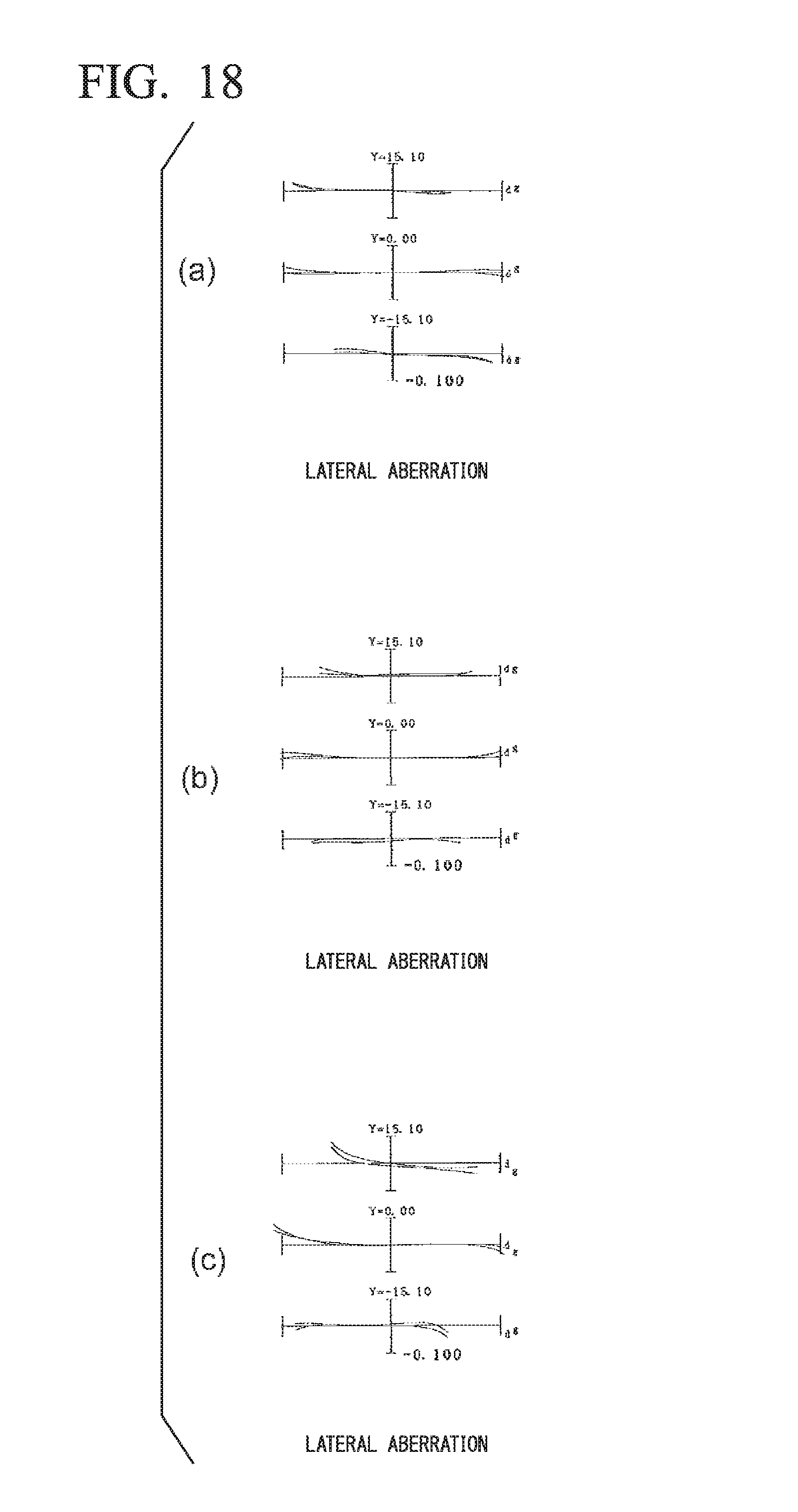
D00019

D00020

D00021
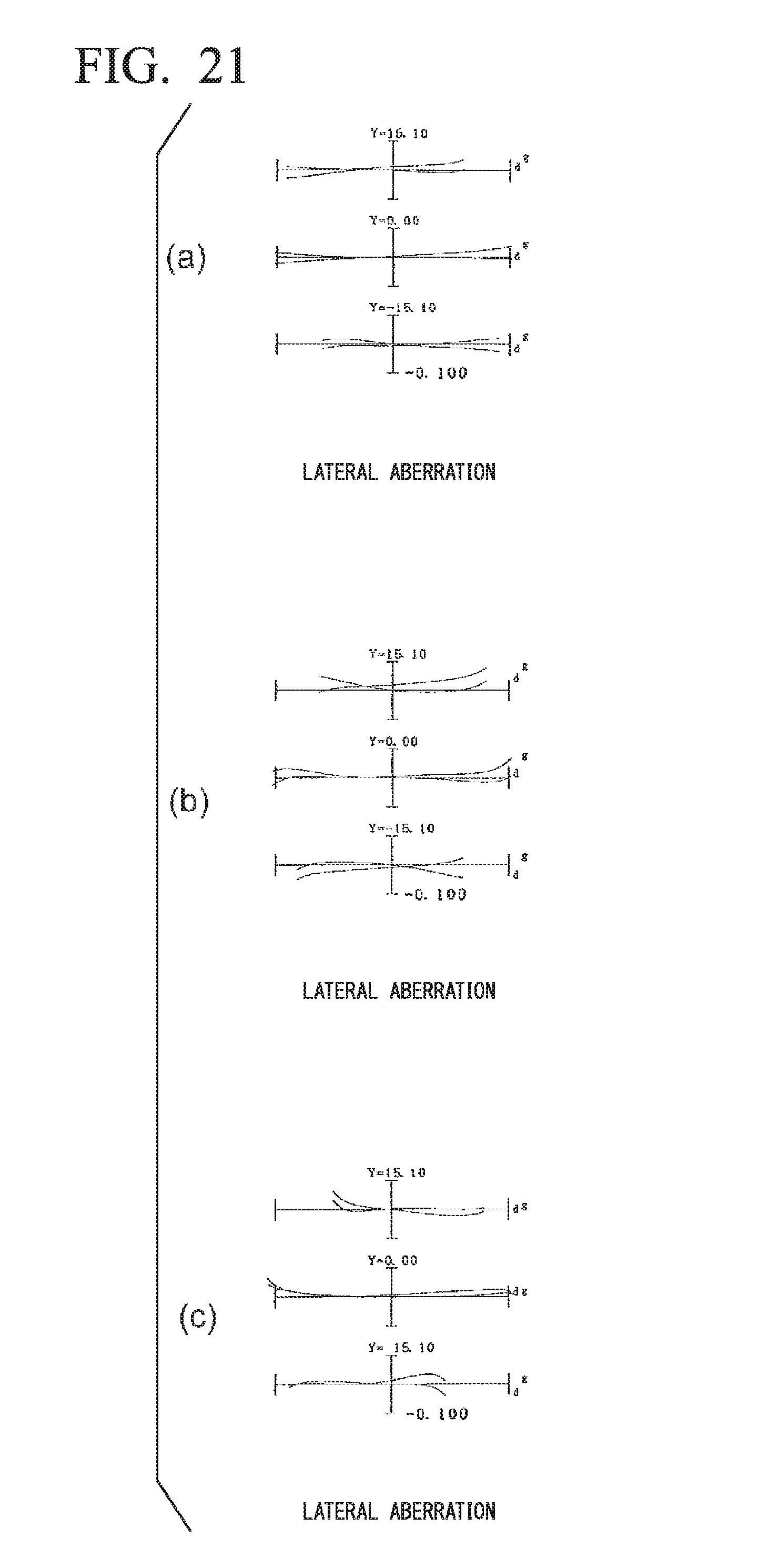
D00022
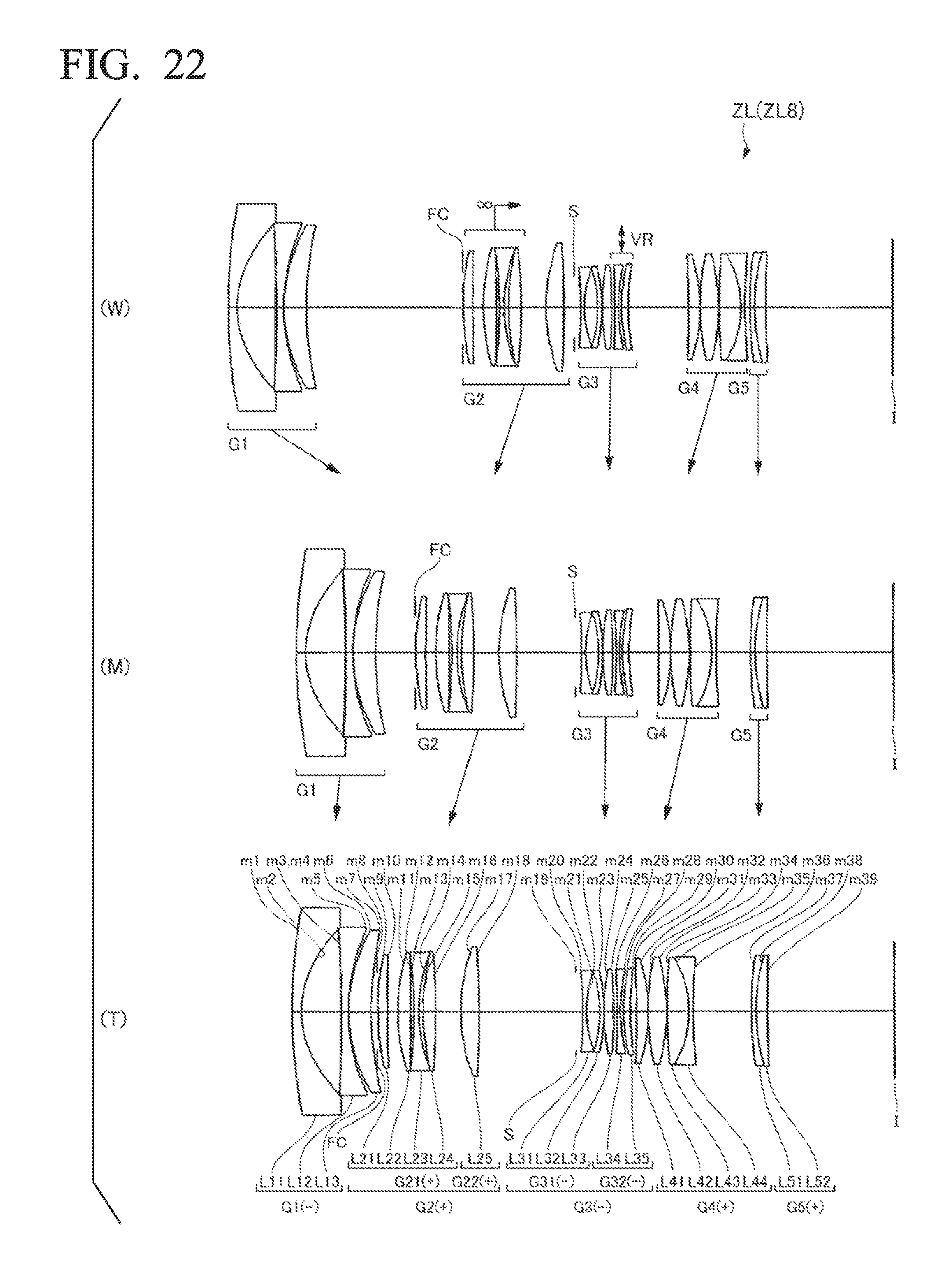
D00023

D00024

D00025

D00026
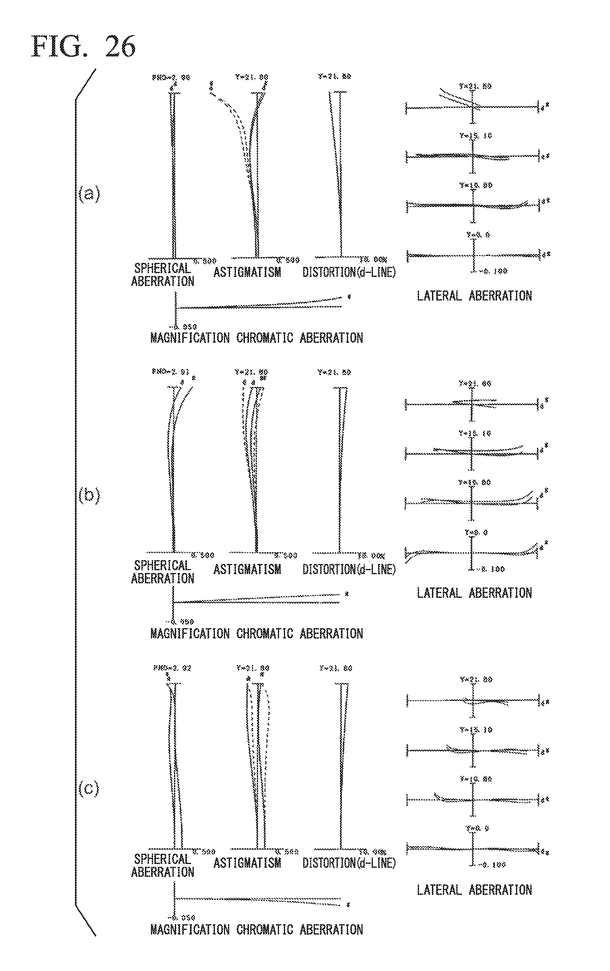
D00027

D00028

D00029

D00030

D00031

D00032

D00033

D00034
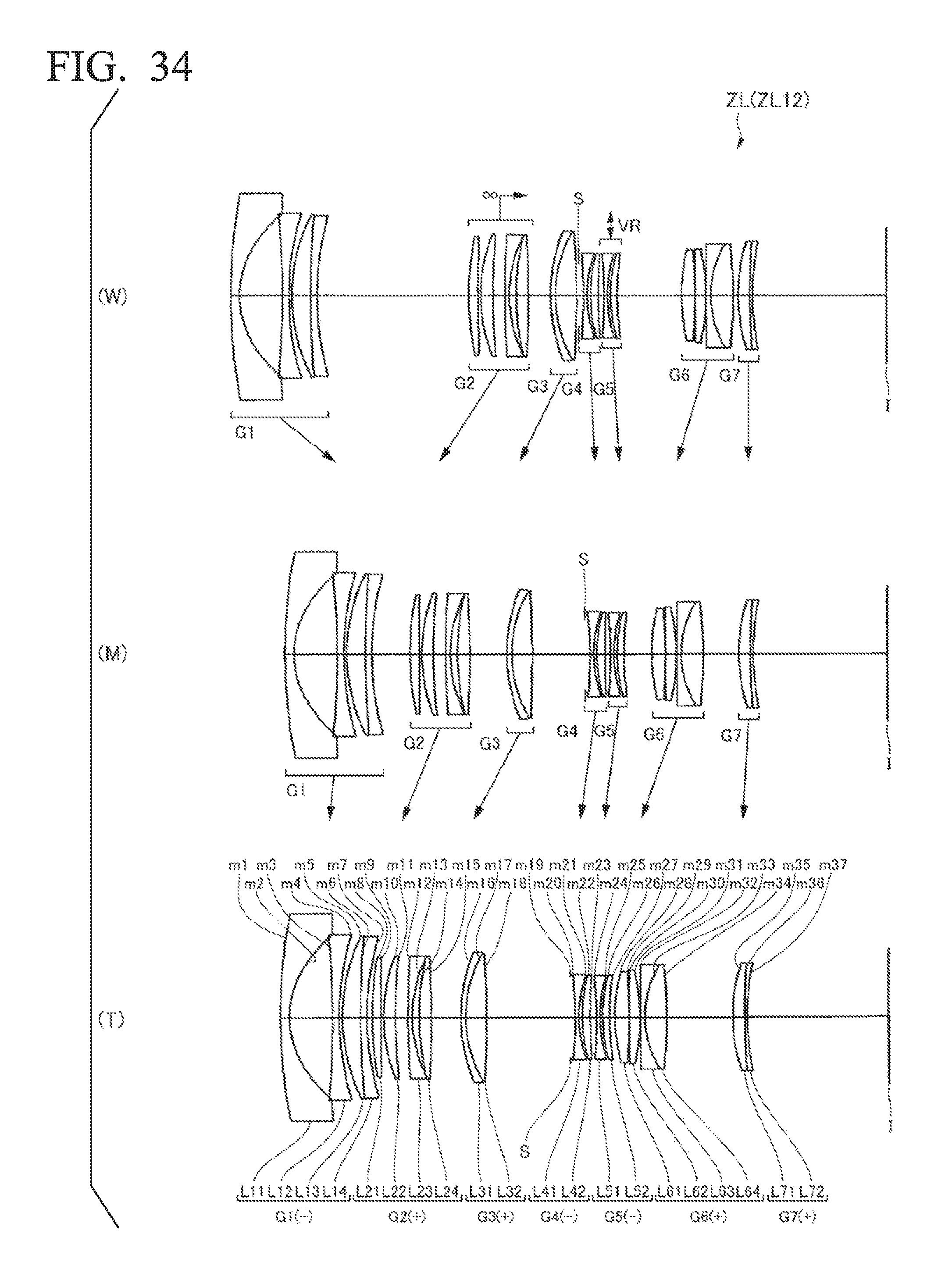
D00035

D00036

D00037

D00038

XML
uspto.report is an independent third-party trademark research tool that is not affiliated, endorsed, or sponsored by the United States Patent and Trademark Office (USPTO) or any other governmental organization. The information provided by uspto.report is based on publicly available data at the time of writing and is intended for informational purposes only.
While we strive to provide accurate and up-to-date information, we do not guarantee the accuracy, completeness, reliability, or suitability of the information displayed on this site. The use of this site is at your own risk. Any reliance you place on such information is therefore strictly at your own risk.
All official trademark data, including owner information, should be verified by visiting the official USPTO website at www.uspto.gov. This site is not intended to replace professional legal advice and should not be used as a substitute for consulting with a legal professional who is knowledgeable about trademark law.