Spinal nerve decompression systems, dilation systems, and methods of using the same
Choi , et al. J
U.S. patent number 10,524,772 [Application Number 15/309,164] was granted by the patent office on 2020-01-07 for spinal nerve decompression systems, dilation systems, and methods of using the same. This patent grant is currently assigned to VertiFlex, Inc.. The grantee listed for this patent is VertiFlex, Inc.. Invention is credited to Andy Choi, Martin Leugers, Kim Nguyen.


View All Diagrams
| United States Patent | 10,524,772 |
| Choi , et al. | January 7, 2020 |
Spinal nerve decompression systems, dilation systems, and methods of using the same
Abstract
A method for treating spinal nerve compression includes sequential dilation to position an instrument cannula along a patient's spine. Instruments can be delivered through the instrument cannula to remove targeted tissue for a decompression procedure. One of the instruments can be a reamer instrument configured to abrade, cut, or otherwise affect tissue along the patient's spine.
| Inventors: | Choi; Andy (Irvine, CA), Nguyen; Kim (Oceanside, CA), Leugers; Martin (Newark, CA) | ||||||||||
|---|---|---|---|---|---|---|---|---|---|---|---|
| Applicant: |
|
||||||||||
| Assignee: | VertiFlex, Inc. (San Clemente,
CA) |
||||||||||
| Family ID: | 54392969 | ||||||||||
| Appl. No.: | 15/309,164 | ||||||||||
| Filed: | May 6, 2015 | ||||||||||
| PCT Filed: | May 06, 2015 | ||||||||||
| PCT No.: | PCT/US2015/029537 | ||||||||||
| 371(c)(1),(2),(4) Date: | November 04, 2016 | ||||||||||
| PCT Pub. No.: | WO2015/171814 | ||||||||||
| PCT Pub. Date: | November 12, 2015 |
Prior Publication Data
| Document Identifier | Publication Date | |
|---|---|---|
| US 20170071588 A1 | Mar 16, 2017 | |
Related U.S. Patent Documents
| Application Number | Filing Date | Patent Number | Issue Date | ||
|---|---|---|---|---|---|
| 61990030 | May 7, 2014 | ||||
| 62060965 | Oct 7, 2014 | ||||
| Current U.S. Class: | 1/1 |
| Current CPC Class: | A61B 17/1671 (20130101); A61B 1/00154 (20130101); A61B 1/3135 (20130101); A61B 90/361 (20160201); A61B 90/30 (20160201); A61B 1/00147 (20130101); A61M 29/00 (20130101); A61B 17/0293 (20130101); A61B 17/0218 (20130101); A61B 1/07 (20130101); A61B 17/3401 (20130101); A61B 1/32 (20130101); A61B 17/3423 (20130101); A61B 1/00087 (20130101); A61B 2017/0256 (20130101); A61B 17/32002 (20130101); A61B 2017/320008 (20130101); A61B 2017/3407 (20130101); A61B 2090/062 (20160201); A61B 2090/306 (20160201); A61B 2017/00477 (20130101) |
| Current International Class: | A61B 17/02 (20060101); A61B 90/30 (20160101); A61B 1/00 (20060101); A61B 1/313 (20060101); A61M 29/00 (20060101); A61B 1/07 (20060101); A61B 1/32 (20060101); A61B 17/34 (20060101) |
References Cited [Referenced By]
U.S. Patent Documents
| 2248054 | July 1941 | Becker |
| 2677369 | May 1954 | Knowles |
| 3242120 | March 1966 | Steuber |
| 3486505 | December 1969 | Morrison |
| 3648691 | March 1972 | Lumb et al. |
| 3986383 | October 1976 | Petteys |
| 4545374 | October 1985 | Jacobson |
| 4632101 | December 1986 | Freedland |
| 4685447 | August 1987 | Iversen et al. |
| 4799484 | January 1989 | Smith et al. |
| 4863476 | September 1989 | Shepperd |
| 4895564 | January 1990 | Farrell |
| 4986831 | January 1991 | King et al. |
| 5011484 | April 1991 | Breard et al. |
| 5015247 | May 1991 | Michelson |
| 5019081 | May 1991 | Watanabe |
| 5040542 | August 1991 | Gray |
| 5059193 | October 1991 | Kuslich |
| 5092866 | March 1992 | Breard et al. |
| 5178628 | January 1993 | Otsuka et al. |
| 5180393 | January 1993 | Commarmond et al. |
| 5182281 | January 1993 | Frigola-Constansa et al. |
| 5188281 | February 1993 | Fujiwara et al. |
| 5192281 | March 1993 | de la Caffiniere |
| 5195526 | March 1993 | Michelson |
| 5298253 | March 1994 | LeFiles et al. |
| 5368594 | November 1994 | Martin et al. |
| 5390683 | February 1995 | Pisharodi |
| 5415661 | May 1995 | Holmes |
| 5456722 | October 1995 | McLeod et al. |
| 5462738 | October 1995 | LeFiles et al. |
| 5472452 | December 1995 | Trott |
| 5484437 | January 1996 | Michelson |
| 5487739 | January 1996 | Aebischer et al. |
| 5489308 | February 1996 | Kuslich et al. |
| 5496318 | March 1996 | Howland et al. |
| 5531748 | July 1996 | de la Caffiniere et al. |
| 5549679 | August 1996 | Kuslich |
| 5571189 | November 1996 | Kuslich |
| 5591165 | January 1997 | Jackson |
| 5609634 | March 1997 | Voydeville et al. |
| 5609636 | March 1997 | Kohrs et al. |
| 5645599 | July 1997 | Samani et al. |
| 5654599 | August 1997 | Casper |
| 5658337 | August 1997 | Kohrs et al. |
| 5674295 | October 1997 | Ray et al. |
| 5700264 | December 1997 | Zucherman et al. |
| 5725582 | March 1998 | Bevan et al. |
| 5741253 | April 1998 | Michelson |
| 5746720 | May 1998 | Stouder, Jr. |
| 5762629 | June 1998 | Kambin |
| 5836948 | November 1998 | Zucherman et al. |
| 5860977 | January 1999 | Zucherman et al. |
| 5863948 | January 1999 | Epstein et al. |
| 5876404 | March 1999 | Zucherman et al. |
| RE36211 | May 1999 | Nonomura et al. |
| 5904636 | May 1999 | Chen et al. |
| 5904686 | May 1999 | Zucherman et al. |
| 5928207 | July 1999 | Pisano et al. |
| 5948017 | September 1999 | Taheri |
| 5972015 | October 1999 | Scribner et al. |
| 6039761 | March 2000 | Li et al. |
| 6045552 | April 2000 | Zucherman et al. |
| 6048342 | April 2000 | Zucherman et al. |
| 6048345 | April 2000 | Berke et al. |
| 6066154 | May 2000 | Reiley et al. |
| 6068630 | May 2000 | Zucherman et al. |
| 6074390 | June 2000 | Zucherman et al. |
| 6080155 | June 2000 | Michelson |
| 6080157 | June 2000 | Cathro et al. |
| 6090112 | July 2000 | Zucherman et al. |
| 6096038 | August 2000 | Michelson |
| 6102928 | August 2000 | Bonutti |
| D433193 | October 2000 | Gaw et al. |
| 6132464 | October 2000 | Martin et al. |
| 6149642 | November 2000 | Gerhart et al. |
| 6149652 | November 2000 | Zucherman et al. |
| 6152926 | November 2000 | Zucherman et al. |
| 6156038 | December 2000 | Zucherman et al. |
| 6159215 | December 2000 | Urbahns et al. |
| 6179873 | January 2001 | Zientek |
| 6183471 | February 2001 | Zucherman et al. |
| 6190387 | February 2001 | Zucherman et al. |
| 6225048 | May 2001 | Soderberg-Naucler et al. |
| 6235030 | May 2001 | Zucherman et al. |
| 6238397 | May 2001 | Zucherman et al. |
| 6264651 | July 2001 | Underwood et al. |
| 6264656 | July 2001 | Michelson |
| 6267765 | July 2001 | Taylor et al. |
| 6270498 | August 2001 | Michelson |
| 6280444 | August 2001 | Zucherman et al. |
| 6312431 | November 2001 | Asfora |
| 6328730 | December 2001 | Harkrider, Jr. |
| 6332882 | December 2001 | Zucherman et al. |
| 6332883 | December 2001 | Zucherman et al. |
| 6336930 | January 2002 | Stalcup et al. |
| 6348053 | February 2002 | Cachia |
| 6364883 | April 2002 | Santilli |
| 6371989 | April 2002 | Chauvin et al. |
| 6375682 | April 2002 | Fleischmann et al. |
| 6379355 | April 2002 | Zucherman et al. |
| 6387130 | May 2002 | Stone et al. |
| 6395032 | May 2002 | Gauchet et al. |
| 6402740 | June 2002 | Ellis et al. |
| 6402750 | June 2002 | Atkinson et al. |
| 6402784 | June 2002 | Wardlaw et al. |
| 6413228 | July 2002 | Hung et al. |
| 6419676 | July 2002 | Zucherman et al. |
| 6419677 | July 2002 | Zucherman et al. |
| 6440169 | August 2002 | Elberg et al. |
| 6443988 | September 2002 | Felt et al. |
| 6447547 | September 2002 | Michelson |
| 6451019 | September 2002 | Zucherman et al. |
| 6451020 | September 2002 | Zucherman et al. |
| 6464682 | October 2002 | Snoke |
| 6471976 | October 2002 | Taylor et al. |
| 6478796 | November 2002 | Zucherman et al. |
| 6478822 | November 2002 | Leroux et al. |
| 6500178 | December 2002 | Zucherman et al. |
| 6514256 | February 2003 | Zucherman et al. |
| 6530925 | March 2003 | Boudard et al. |
| 6558333 | May 2003 | Gilboa et al. |
| 6565570 | May 2003 | Sterett et al. |
| 6572617 | June 2003 | Senegas et al. |
| 6575981 | June 2003 | Boyd et al. |
| 6579281 | June 2003 | Palmer et al. |
| 6579319 | June 2003 | Goble et al. |
| 6582433 | June 2003 | Yun |
| 6582451 | June 2003 | Marucci et al. |
| 6599292 | July 2003 | Ray |
| 6602248 | August 2003 | Sharps et al. |
| 6610065 | August 2003 | Branch et al. |
| 6610091 | August 2003 | Reiley |
| 6626944 | September 2003 | Taylor et al. |
| 6645207 | November 2003 | Dixon et al. |
| 6645211 | November 2003 | Magana |
| 6652527 | November 2003 | Zucherman et al. |
| 6652534 | November 2003 | Zucherman et al. |
| 6663637 | December 2003 | Dixon et al. |
| 6679886 | January 2004 | Weikel et al. |
| 6695842 | February 2004 | Zucherman et al. |
| 6699246 | March 2004 | Zucherman et al. |
| 6699247 | March 2004 | Zucherman et al. |
| 6702847 | March 2004 | DiCarlo |
| 6712819 | March 2004 | Zucherman et al. |
| 6716215 | April 2004 | David et al. |
| 6716245 | April 2004 | Pasquet et al. |
| 6726690 | April 2004 | Eckman |
| 6733534 | May 2004 | Sherman |
| 6746485 | June 2004 | Zucherman et al. |
| 6761720 | July 2004 | Senegas et al. |
| 6783529 | August 2004 | Hover et al. |
| 6783546 | August 2004 | Zucherman et al. |
| 6796983 | September 2004 | Zucherman et al. |
| 6805697 | October 2004 | Helm et al. |
| 6835205 | December 2004 | Atkinson et al. |
| 6840944 | January 2005 | Suddaby |
| 6858029 | February 2005 | Yeh |
| 6869398 | March 2005 | Obenchain et al. |
| 6875212 | April 2005 | Shaolian et al. |
| 6902566 | June 2005 | Zucherman et al. |
| 6926728 | August 2005 | Zucherman et al. |
| 6946000 | September 2005 | Senegas et al. |
| 6949123 | September 2005 | Reiley |
| 6966930 | November 2005 | Arnin et al. |
| 6974478 | December 2005 | Reiley et al. |
| 7011685 | March 2006 | Arnin et al. |
| 7029473 | April 2006 | Zucherman et al. |
| 7033358 | April 2006 | Taylor et al. |
| 7048736 | May 2006 | Robinson et al. |
| 7070598 | July 2006 | Lim et al. |
| 7083649 | August 2006 | Zucherman et al. |
| 7087055 | August 2006 | Lim et al. |
| 7087083 | August 2006 | Pasquet et al. |
| 7097648 | August 2006 | Globerman et al. |
| 7101375 | September 2006 | Zucherman et al. |
| 7163558 | January 2007 | Senegas et al. |
| 7179225 | February 2007 | Shluzas et al. |
| 7187064 | March 2007 | Tzu et al. |
| 7189234 | March 2007 | Zucherman et al. |
| 7189236 | March 2007 | Taylor et al. |
| 7201751 | April 2007 | Zucherman et al. |
| 7217291 | May 2007 | Zucherman et al. |
| 7223289 | May 2007 | Trieu et al. |
| 7229441 | June 2007 | Trieu et al. |
| 7238204 | July 2007 | Le Couedic et al. |
| 7252673 | August 2007 | Lim |
| 7273496 | September 2007 | Mitchell |
| 7282063 | October 2007 | Cohen et al. |
| 7297162 | November 2007 | Mujwid |
| 7306628 | December 2007 | Zucherman et al. |
| 7318839 | January 2008 | Malberg et al. |
| 7320707 | January 2008 | Zucherman et al. |
| 7335200 | February 2008 | Carli |
| 7335203 | February 2008 | Winslow et al. |
| 7354453 | April 2008 | McAfee |
| 7384340 | June 2008 | Eguchi et al. |
| 7390330 | June 2008 | Harp |
| 7410501 | August 2008 | Michelson |
| 7442208 | October 2008 | Mathieu et al. |
| 7445637 | November 2008 | Taylor |
| 7473268 | January 2009 | Zucherman et al. |
| 7476251 | January 2009 | Zucherman et al. |
| 7481839 | January 2009 | Zucherman et al. |
| 7481840 | January 2009 | Zucherman et al. |
| 7491204 | February 2009 | Marnay et al. |
| 7497859 | March 2009 | Zucherman et al. |
| 7503935 | March 2009 | Zucherman et al. |
| 7504798 | March 2009 | Kawada et al. |
| 7510567 | March 2009 | Zucherman et al. |
| 7520887 | April 2009 | Maxy et al. |
| 7520899 | April 2009 | Zucherman et al. |
| 7547308 | June 2009 | Bertagnoli et al. |
| 7549999 | June 2009 | Zucherman et al. |
| 7550009 | June 2009 | Arnin et al. |
| 7565259 | July 2009 | Sheng et al. |
| 7572276 | August 2009 | Lim et al. |
| 7575600 | August 2009 | Zucherman et al. |
| 7585313 | September 2009 | Kwak et al. |
| 7585316 | September 2009 | Trieu |
| 7588588 | September 2009 | Spitler et al. |
| 7591851 | September 2009 | Winslow et al. |
| 7601170 | October 2009 | Winslow et al. |
| 7621939 | November 2009 | Zucherman et al. |
| 7635377 | December 2009 | Zucherman et al. |
| 7635378 | December 2009 | Zucherman et al. |
| 7637950 | December 2009 | Baccelli et al. |
| 7658752 | February 2010 | Labrom et al. |
| 7662187 | February 2010 | Zucherman et al. |
| 7666186 | February 2010 | Harp |
| 7666209 | February 2010 | Zucherman et al. |
| 7666228 | February 2010 | Le Couedic et al. |
| 7670377 | March 2010 | Zucherman et al. |
| 7682376 | March 2010 | Trieu |
| 7691146 | April 2010 | Zucherman et al. |
| 7695513 | April 2010 | Zucherman et al. |
| 7699852 | April 2010 | Frankel et al. |
| 7699873 | April 2010 | Stevenson et al. |
| D618796 | June 2010 | Cantu et al. |
| 7727233 | June 2010 | Blackwell et al. |
| 7727241 | June 2010 | Gorensek et al. |
| 7731751 | June 2010 | Butler et al. |
| 7742795 | June 2010 | Stone et al. |
| 7749231 | July 2010 | Bonvallet et al. |
| 7749252 | July 2010 | Zucherman et al. |
| 7749253 | July 2010 | Zucherman et al. |
| 7753938 | July 2010 | Aschmann et al. |
| 7758619 | July 2010 | Zucherman et al. |
| 7758647 | July 2010 | Arnin et al. |
| 7763028 | July 2010 | Lim et al. |
| 7763050 | July 2010 | Winslow et al. |
| 7763051 | July 2010 | Labrom et al. |
| 7763073 | July 2010 | Hawkins et al. |
| 7763074 | July 2010 | Altarac et al. |
| 7766967 | August 2010 | Francis |
| 7776090 | August 2010 | Winslow et al. |
| 7780709 | August 2010 | Bruneau et al. |
| 7789898 | September 2010 | Peterman |
| 7794476 | September 2010 | Wisnewski |
| 7803190 | September 2010 | Zucherman et al. |
| 7806911 | October 2010 | Peckham |
| 7811308 | October 2010 | Arnin et al. |
| 7811322 | October 2010 | Arnin et al. |
| 7811323 | October 2010 | Arnin et al. |
| 7811324 | October 2010 | Arnin et al. |
| 7811330 | October 2010 | Arnin et al. |
| 7819921 | October 2010 | Grotz |
| 7828822 | November 2010 | Zucherman et al. |
| 7828849 | November 2010 | Lim |
| 7833272 | November 2010 | Arnin et al. |
| 7837687 | November 2010 | Harp |
| 7837688 | November 2010 | Boyer, II et al. |
| 7837700 | November 2010 | Harp |
| 7837711 | November 2010 | Bruneau et al. |
| 7837734 | November 2010 | Zucherman et al. |
| 7846183 | December 2010 | Blain |
| 7846185 | December 2010 | Cads et al. |
| 7846186 | December 2010 | Taylor |
| 7857815 | December 2010 | Zucherman et al. |
| 7862569 | January 2011 | Zucherman et al. |
| 7862586 | January 2011 | Malek |
| 7862590 | January 2011 | Lim et al. |
| 7862592 | January 2011 | Peterson et al. |
| 7862615 | January 2011 | Carli et al. |
| 7867276 | January 2011 | Matge et al. |
| 7871426 | January 2011 | Chin et al. |
| 7896879 | March 2011 | Solsberg et al. |
| 7942830 | May 2011 | Solsberg et al. |
| 7955392 | June 2011 | Dewey et al. |
| 8012207 | September 2011 | Kim |
| 8025684 | September 2011 | Garcia-Bengochea et al. |
| 8057513 | November 2011 | Kohm et al. |
| 8062332 | November 2011 | Cunningham et al. |
| 8100823 | January 2012 | Harp |
| 8123782 | February 2012 | Altarac et al. |
| 8123807 | February 2012 | Kim |
| 8128662 | March 2012 | Altarac et al. |
| 8152837 | April 2012 | Altarac et al. |
| 8167944 | May 2012 | Kim |
| 8226690 | July 2012 | Altarac et al. |
| 8273108 | September 2012 | Altarac et al. |
| 8277488 | October 2012 | Altarac et al. |
| 8292922 | October 2012 | Altarac et al. |
| 8317864 | November 2012 | Kim |
| 8409282 | April 2013 | Kim |
| 8425559 | April 2013 | Tebbe et al. |
| 8608762 | December 2013 | Solsberg et al. |
| 8613747 | December 2013 | Altarac et al. |
| 8628574 | January 2014 | Altarac et al. |
| 8696671 | April 2014 | Solsberg et al. |
| 8734477 | May 2014 | Solsberg et al. |
| 8740948 | June 2014 | Reglos et al. |
| 8845726 | September 2014 | Tebbe et al. |
| 8864828 | October 2014 | Altarac et al. |
| 8882772 | November 2014 | Solsberg et al. |
| 8894653 | November 2014 | Solsberg et al. |
| 8900271 | December 2014 | Kim |
| 8945183 | February 2015 | Altarac et al. |
| 9023084 | May 2015 | Kim |
| 9039742 | May 2015 | Altarac et al. |
| 9119680 | September 2015 | Altarac et al. |
| 9125692 | September 2015 | Kim |
| 9155570 | October 2015 | Altarac et al. |
| 9155572 | October 2015 | Altarac et al. |
| 9161783 | October 2015 | Altarac et al. |
| 9186186 | November 2015 | Reglos et al. |
| 9211146 | December 2015 | Kim |
| 9283005 | March 2016 | Tebbe et al. |
| 9314279 | April 2016 | Kim |
| 9393055 | July 2016 | Altarac et al. |
| 9445843 | September 2016 | Altarac et al. |
| 2001/0031965 | October 2001 | Zucherman et al. |
| 2002/0042607 | April 2002 | Palmer et al. |
| 2002/0143331 | October 2002 | Zucherman et al. |
| 2003/0040746 | February 2003 | Mitchell et al. |
| 2003/0040753 | February 2003 | Daum et al. |
| 2003/0074075 | April 2003 | Thomas et al. |
| 2003/0149438 | August 2003 | Nichols et al. |
| 2003/0153976 | August 2003 | Cauthen et al. |
| 2003/0176921 | September 2003 | Lawson |
| 2003/0220643 | November 2003 | Ferree |
| 2003/0220650 | November 2003 | Major et al. |
| 2003/0233098 | December 2003 | Markworth |
| 2004/0087947 | May 2004 | Lim et al. |
| 2004/0106997 | June 2004 | Lieberson |
| 2004/0106999 | June 2004 | Mathews |
| 2004/0167625 | August 2004 | Beyar et al. |
| 2004/0220568 | November 2004 | Zucherman et al. |
| 2005/0049708 | March 2005 | Atkinson et al. |
| 2005/0075634 | April 2005 | Zucherman et al. |
| 2005/0090822 | April 2005 | DiPoto |
| 2005/0101955 | May 2005 | Zucherman et al. |
| 2005/0125066 | June 2005 | McAfee |
| 2005/0143738 | June 2005 | Zucherman et al. |
| 2005/0165398 | July 2005 | Reiley |
| 2005/0192586 | September 2005 | Zucherman et al. |
| 2005/0192671 | September 2005 | Bao et al. |
| 2005/0209603 | September 2005 | Zucherman et al. |
| 2005/0216087 | September 2005 | Zucherman et al. |
| 2005/0228383 | October 2005 | Zucherman et al. |
| 2005/0228384 | October 2005 | Zucherman et al. |
| 2005/0228426 | October 2005 | Campbell |
| 2005/0245937 | November 2005 | Winslow |
| 2005/0278036 | December 2005 | Leonard et al. |
| 2006/0036258 | February 2006 | Zucherman et al. |
| 2006/0064165 | March 2006 | Zucherman et al. |
| 2006/0064166 | March 2006 | Zucherman et al. |
| 2006/0074431 | April 2006 | Sutton et al. |
| 2006/0084976 | April 2006 | Borgstrom et al. |
| 2006/0084983 | April 2006 | Kim |
| 2006/0084985 | April 2006 | Kim |
| 2006/0084988 | April 2006 | Kim |
| 2006/0084991 | April 2006 | Borgstrom et al. |
| 2006/0085069 | April 2006 | Kim |
| 2006/0085070 | April 2006 | Kim |
| 2006/0085074 | April 2006 | Raiszadeh |
| 2006/0089718 | April 2006 | Zucherman et al. |
| 2006/0102269 | May 2006 | Uchida et al. |
| 2006/0122620 | June 2006 | Kim |
| 2006/0149254 | July 2006 | Lauryssen et al. |
| 2006/0149289 | July 2006 | Winslow et al. |
| 2006/0167416 | July 2006 | Mathis et al. |
| 2006/0195102 | August 2006 | Malandain |
| 2006/0217811 | September 2006 | Lambrecht et al. |
| 2006/0224159 | October 2006 | Anderson |
| 2006/0235386 | October 2006 | Anderson |
| 2006/0241597 | October 2006 | Mitchell et al. |
| 2006/0241614 | October 2006 | Bruneau et al. |
| 2006/0241757 | October 2006 | Anderson |
| 2006/0247623 | November 2006 | Anderson et al. |
| 2006/0247632 | November 2006 | Winslow et al. |
| 2006/0247633 | November 2006 | Winslow et al. |
| 2006/0247650 | November 2006 | Yerby et al. |
| 2006/0247773 | November 2006 | Stamp |
| 2006/0264938 | November 2006 | Zucherman et al. |
| 2006/0264939 | November 2006 | Zucherman et al. |
| 2006/0265066 | November 2006 | Zucherman et al. |
| 2006/0265067 | November 2006 | Zucherman et al. |
| 2006/0271044 | November 2006 | Petrini et al. |
| 2006/0271049 | November 2006 | Zucherman et al. |
| 2006/0271055 | November 2006 | Thramann |
| 2006/0271061 | November 2006 | Beyar et al. |
| 2006/0271194 | November 2006 | Zucherman et al. |
| 2006/0276801 | December 2006 | Yerby et al. |
| 2006/0276897 | December 2006 | Winslow et al. |
| 2006/0282077 | December 2006 | Labrom et al. |
| 2006/0282078 | December 2006 | Labrom et al. |
| 2007/0016196 | January 2007 | Winslow et al. |
| 2007/0055237 | March 2007 | Edidin et al. |
| 2007/0055246 | March 2007 | Zucherman et al. |
| 2007/0073289 | March 2007 | Kwak et al. |
| 2007/0100340 | May 2007 | Lange et al. |
| 2007/0100366 | May 2007 | Dziedzic et al. |
| 2007/0123863 | May 2007 | Winslow et al. |
| 2007/0123904 | May 2007 | Stad et al. |
| 2007/0161991 | July 2007 | Altarac et al. |
| 2007/0161993 | July 2007 | Lowery et al. |
| 2007/0173818 | July 2007 | Hestad et al. |
| 2007/0173821 | July 2007 | Trieu |
| 2007/0173822 | July 2007 | Bruneau et al. |
| 2007/0173823 | July 2007 | Dewey et al. |
| 2007/0173832 | July 2007 | Tebbe et al. |
| 2007/0173939 | July 2007 | Kim et al. |
| 2007/0179500 | August 2007 | Chin et al. |
| 2007/0185490 | August 2007 | Implicito |
| 2007/0191948 | August 2007 | Arnin et al. |
| 2007/0191991 | August 2007 | Addink |
| 2007/0198045 | August 2007 | Morton et al. |
| 2007/0198091 | August 2007 | Boyer et al. |
| 2007/0203493 | August 2007 | Zucherman et al. |
| 2007/0203495 | August 2007 | Zucherman et al. |
| 2007/0203496 | August 2007 | Zucherman et al. |
| 2007/0203497 | August 2007 | Zucherman et al. |
| 2007/0203501 | August 2007 | Zucherman et al. |
| 2007/0208345 | September 2007 | Marnay et al. |
| 2007/0208346 | September 2007 | Marnay et al. |
| 2007/0208366 | September 2007 | Pellegrino et al. |
| 2007/0210018 | September 2007 | Wallwiener et al. |
| 2007/0225706 | September 2007 | Clark et al. |
| 2007/0225724 | September 2007 | Edmond |
| 2007/0225807 | September 2007 | Phan et al. |
| 2007/0225814 | September 2007 | Atkinson et al. |
| 2007/0233068 | October 2007 | Bruneau et al. |
| 2007/0233074 | October 2007 | Anderson et al. |
| 2007/0233076 | October 2007 | Trieu |
| 2007/0233077 | October 2007 | Khalili |
| 2007/0233081 | October 2007 | Pasquet et al. |
| 2007/0233082 | October 2007 | Chin et al. |
| 2007/0233083 | October 2007 | Abdou |
| 2007/0233084 | October 2007 | Betz et al. |
| 2007/0233088 | October 2007 | Edmond |
| 2007/0233089 | October 2007 | DiPoto et al. |
| 2007/0233096 | October 2007 | Garcia-Bengochea |
| 2007/0233098 | October 2007 | Mastrorio et al. |
| 2007/0233129 | October 2007 | Bertagnoli et al. |
| 2007/0250060 | October 2007 | Anderson et al. |
| 2007/0260245 | November 2007 | Malandain et al. |
| 2007/0265623 | November 2007 | Malandain et al. |
| 2007/0265624 | November 2007 | Zucherman et al. |
| 2007/0265625 | November 2007 | Zucherman et al. |
| 2007/0265626 | November 2007 | Seme |
| 2007/0270822 | November 2007 | Heinz |
| 2007/0270823 | November 2007 | Trieu et al. |
| 2007/0270824 | November 2007 | Lim et al. |
| 2007/0270826 | November 2007 | Trieu et al. |
| 2007/0270827 | November 2007 | Lim et al. |
| 2007/0270828 | November 2007 | Bruneau et al. |
| 2007/0270829 | November 2007 | Carls et al. |
| 2007/0270834 | November 2007 | Bruneau et al. |
| 2007/0272259 | November 2007 | Allard et al. |
| 2007/0276368 | November 2007 | Trieu et al. |
| 2007/0276369 | November 2007 | Allard et al. |
| 2007/0276372 | November 2007 | Malandain et al. |
| 2007/0276373 | November 2007 | Malandain |
| 2007/0276390 | November 2007 | Solsberg et al. |
| 2007/0276493 | November 2007 | Malandain et al. |
| 2007/0276496 | November 2007 | Lange et al. |
| 2007/0276497 | November 2007 | Anderson |
| 2007/0276500 | November 2007 | Zucherman et al. |
| 2008/0015700 | January 2008 | Zucherman et al. |
| 2008/0021468 | January 2008 | Zucherman et al. |
| 2008/0021560 | January 2008 | Zucherman et al. |
| 2008/0021561 | January 2008 | Zucherman et al. |
| 2008/0027545 | January 2008 | Zucherman et al. |
| 2008/0027552 | January 2008 | Zucherman et al. |
| 2008/0027553 | January 2008 | Zucherman et al. |
| 2008/0033445 | February 2008 | Zucherman et al. |
| 2008/0033553 | February 2008 | Zucherman et al. |
| 2008/0033558 | February 2008 | Zucherman et al. |
| 2008/0033559 | February 2008 | Zucherman et al. |
| 2008/0039853 | February 2008 | Zucherman et al. |
| 2008/0039858 | February 2008 | Zucherman et al. |
| 2008/0039859 | February 2008 | Zucherman et al. |
| 2008/0039945 | February 2008 | Zucherman et al. |
| 2008/0039946 | February 2008 | Zucherman et al. |
| 2008/0039947 | February 2008 | Zucherman et al. |
| 2008/0045958 | February 2008 | Zucherman et al. |
| 2008/0045959 | February 2008 | Zucherman et al. |
| 2008/0046081 | February 2008 | Zucherman et al. |
| 2008/0046085 | February 2008 | Zucherman et al. |
| 2008/0046086 | February 2008 | Zucherman et al. |
| 2008/0046087 | February 2008 | Zucherman et al. |
| 2008/0046088 | February 2008 | Zucherman et al. |
| 2008/0051785 | February 2008 | Zucherman et al. |
| 2008/0051898 | February 2008 | Zucherman et al. |
| 2008/0051899 | February 2008 | Zucherman et al. |
| 2008/0051904 | February 2008 | Zucherman et al. |
| 2008/0051905 | February 2008 | Zucherman et al. |
| 2008/0058806 | March 2008 | Klyce et al. |
| 2008/0058807 | March 2008 | Klyce et al. |
| 2008/0058808 | March 2008 | Klyce et al. |
| 2008/0058941 | March 2008 | Zucherman et al. |
| 2008/0065086 | March 2008 | Zucherman et al. |
| 2008/0065212 | March 2008 | Zucherman et al. |
| 2008/0065213 | March 2008 | Zucherman et al. |
| 2008/0065214 | March 2008 | Zucherman et al. |
| 2008/0071280 | March 2008 | Winslow |
| 2008/0071378 | March 2008 | Zucherman et al. |
| 2008/0086212 | April 2008 | Zucherman et al. |
| 2008/0108990 | May 2008 | Mitchell et al. |
| 2008/0114455 | May 2008 | Lange et al. |
| 2008/0132952 | June 2008 | Malandain et al. |
| 2008/0167655 | July 2008 | Wang et al. |
| 2008/0167656 | July 2008 | Zucherman et al. |
| 2008/0172057 | July 2008 | Zucherman et al. |
| 2008/0177272 | July 2008 | Zucherman et al. |
| 2008/0177306 | July 2008 | Lamborne et al. |
| 2008/0177312 | July 2008 | Perez-Cruet et al. |
| 2008/0183210 | July 2008 | Zucherman et al. |
| 2008/0188895 | August 2008 | Cragg et al. |
| 2008/0208344 | August 2008 | Kilpela et al. |
| 2008/0215058 | September 2008 | Zucherman et al. |
| 2008/0221692 | September 2008 | Zucherman et al. |
| 2008/0228225 | September 2008 | Trautwein et al. |
| 2008/0234708 | September 2008 | Houser et al. |
| 2008/0234824 | September 2008 | Youssef et al. |
| 2008/0288075 | November 2008 | Zucherman et al. |
| 2008/0319550 | December 2008 | Altarac et al. |
| 2009/0012528 | January 2009 | Aschmann et al. |
| 2009/0118833 | May 2009 | Hudgins et al. |
| 2009/0125030 | May 2009 | Tebbe et al. |
| 2009/0125036 | May 2009 | Bleich |
| 2009/0138046 | May 2009 | Altarac et al. |
| 2009/0138055 | May 2009 | Altarac et al. |
| 2009/0222043 | September 2009 | Altarac et al. |
| 2009/0248079 | October 2009 | Kwak et al. |
| 2009/0292315 | November 2009 | Trieu |
| 2010/0042217 | February 2010 | Zucherman et al. |
| 2010/0082108 | April 2010 | Zucherman et al. |
| 2010/0114100 | May 2010 | Mehdizade |
| 2010/0131009 | May 2010 | Roebling et al. |
| 2010/0228092 | September 2010 | Ortiz et al. |
| 2010/0234889 | September 2010 | Hess |
| 2010/0262243 | October 2010 | Zucherman et al. |
| 2010/0280551 | November 2010 | Pool et al. |
| 2010/0305611 | December 2010 | Zucherman et al. |
| 2011/0245833 | October 2011 | Anderson |
| 2011/0313457 | December 2011 | Reglos et al. |
| 2012/0078301 | March 2012 | Hess |
| 2012/0158063 | June 2012 | Altarac et al. |
| 2012/0226315 | September 2012 | Altarac et al. |
| 2012/0232552 | September 2012 | Morgenstern Lopez |
| 2012/0303039 | November 2012 | Chin |
| 2012/0330359 | December 2012 | Kim |
| 2013/0012998 | January 2013 | Altarac et al. |
| 2013/0072985 | March 2013 | Kim |
| 2013/0150886 | June 2013 | Altarac et al. |
| 2013/0165974 | June 2013 | Kim |
| 2013/0165975 | June 2013 | Tebbe et al. |
| 2013/0172932 | July 2013 | Altarac et al. |
| 2013/0172933 | July 2013 | Altarac et al. |
| 2013/0289399 | October 2013 | Choi et al. |
| 2013/0289622 | October 2013 | Kim |
| 2014/0081332 | March 2014 | Altarac et al. |
| 2014/0214082 | July 2014 | Reglos et al. |
| 2014/0275992 | September 2014 | Choi et al. |
| 2015/0150598 | June 2015 | Tebbe et al. |
| 2015/0150604 | June 2015 | Kim |
| 2015/0164560 | June 2015 | Altarac et al. |
| 2015/0374415 | December 2015 | Kim |
| 2016/0030092 | February 2016 | Altarac et al. |
| 2016/0045232 | February 2016 | Altarac et al. |
| 2016/0066963 | March 2016 | Kim |
| 2016/0135853 | May 2016 | Altarac et al. |
| 2016/0248222 | August 2016 | Miyata |
| 2016/0317193 | November 2016 | Kim |
| 268461 | Feb 1927 | CA | |||
| 2794456 | Jul 2006 | CN | |||
| 101897603 | Dec 2010 | CN | |||
| 69507480 | Sep 1999 | DE | |||
| 322334 | Jun 1989 | EP | |||
| 0767636 | Apr 1997 | EP | |||
| 0768843 | Apr 1997 | EP | |||
| 0959792 | Dec 1999 | EP | |||
| 1027004 | Aug 2000 | EP | |||
| 1030615 | Aug 2000 | EP | |||
| 1138268 | Oct 2001 | EP | |||
| 1330987 | Jul 2003 | EP | |||
| 1056408 | Dec 2003 | EP | |||
| 1343424 | Sep 2004 | EP | |||
| 1454589 | Sep 2004 | EP | |||
| 1148850 | Apr 2005 | EP | |||
| 1570793 | Sep 2005 | EP | |||
| 1299042 | Mar 2006 | EP | |||
| 1578314 | May 2007 | EP | |||
| 1675535 | May 2007 | EP | |||
| 1861046 | Dec 2007 | EP | |||
| 2681525 | Mar 1993 | FR | |||
| 2722980 | Feb 1996 | FR | |||
| 2816197 | May 2002 | FR | |||
| 2884136 | Oct 2006 | FR | |||
| 2888744 | Jan 2007 | FR | |||
| 988281 | Jan 1983 | SU | |||
| WO-9404088 | Mar 1994 | WO | |||
| WO-9426192 | Nov 1994 | WO | |||
| WO-9525485 | Sep 1995 | WO | |||
| WO-9531158 | Nov 1995 | WO | |||
| WO-9600049 | Jan 1996 | WO | |||
| WO-9829047 | Jul 1998 | WO | |||
| WO-9921500 | May 1999 | WO | |||
| WO-9921501 | May 1999 | WO | |||
| WO-9942051 | Aug 1999 | WO | |||
| WO-0013619 | Mar 2000 | WO | |||
| WO-0044319 | Aug 2000 | WO | |||
| WO-0044321 | Aug 2000 | WO | |||
| WO-0128442 | Apr 2001 | WO | |||
| WO-0191657 | Dec 2001 | WO | |||
| WO-0191658 | Dec 2001 | WO | |||
| WO-0203882 | Jan 2002 | WO | |||
| WO-0207623 | Jan 2002 | WO | |||
| WO-0207624 | Jan 2002 | WO | |||
| WO-02051326 | Jul 2002 | WO | |||
| WO-02067793 | Sep 2002 | WO | |||
| WO-02071960 | Sep 2002 | WO | |||
| WO-02076336 | Oct 2002 | WO | |||
| WO-03007791 | Jan 2003 | WO | |||
| WO-03007829 | Jan 2003 | WO | |||
| WO-03008016 | Jan 2003 | WO | |||
| WO-03015646 | Feb 2003 | WO | |||
| WO-03024298 | Mar 2003 | WO | |||
| WO-03045262 | Jun 2003 | WO | |||
| WO-03099147 | Dec 2003 | WO | |||
| WO-03101350 | Dec 2003 | WO | |||
| WO-04073533 | Sep 2004 | WO | |||
| WO-04110300 | Dec 2004 | WO | |||
| WO-05009300 | Feb 2005 | WO | |||
| WO-05013839 | Feb 2005 | WO | |||
| WO-05025461 | Mar 2005 | WO | |||
| WO-05041799 | May 2005 | WO | |||
| WO-05044152 | May 2005 | WO | |||
| WO-05055868 | Jun 2005 | WO | |||
| WO-05079672 | Sep 2005 | WO | |||
| WO-2005086776 | Sep 2005 | WO | |||
| WO-05115261 | Dec 2005 | WO | |||
| WO-06033659 | Mar 2006 | WO | |||
| WO-06034423 | Mar 2006 | WO | |||
| WO-06039243 | Apr 2006 | WO | |||
| WO-06039260 | Apr 2006 | WO | |||
| WO-06045094 | Apr 2006 | WO | |||
| WO-2006045094 | Apr 2006 | WO | |||
| WO-06063047 | Jun 2006 | WO | |||
| WO-06065774 | Jun 2006 | WO | |||
| WO-2006063047 | Jun 2006 | WO | |||
| WO-2006064356 | Jun 2006 | WO | |||
| WO-2006089085 | Aug 2006 | WO | |||
| WO-06102269 | Sep 2006 | WO | |||
| WO-06102428 | Sep 2006 | WO | |||
| WO-06102485 | Sep 2006 | WO | |||
| WO-06107539 | Oct 2006 | WO | |||
| WO-06110462 | Oct 2006 | WO | |||
| WO-06110464 | Oct 2006 | WO | |||
| WO-06110767 | Oct 2006 | WO | |||
| WO-06113080 | Oct 2006 | WO | |||
| WO-06113406 | Oct 2006 | WO | |||
| WO-06113814 | Oct 2006 | WO | |||
| WO-06118945 | Nov 2006 | WO | |||
| WO-06119235 | Nov 2006 | WO | |||
| WO-06119236 | Nov 2006 | WO | |||
| WO-06135511 | Dec 2006 | WO | |||
| WO-07015028 | Feb 2007 | WO | |||
| WO-07035120 | Mar 2007 | WO | |||
| WO-07075375 | Jul 2007 | WO | |||
| WO-07075788 | Jul 2007 | WO | |||
| WO-07075791 | Jul 2007 | WO | |||
| WO-07089605 | Aug 2007 | WO | |||
| WO-07089905 | Aug 2007 | WO | |||
| WO-07089975 | Aug 2007 | WO | |||
| WO-07097735 | Aug 2007 | WO | |||
| WO-07109402 | Sep 2007 | WO | |||
| WO-07110604 | Oct 2007 | WO | |||
| WO-07111795 | Oct 2007 | WO | |||
| WO-07111979 | Oct 2007 | WO | |||
| WO-07111999 | Oct 2007 | WO | |||
| WO-07117882 | Oct 2007 | WO | |||
| WO-07121070 | Oct 2007 | WO | |||
| WO-07127550 | Nov 2007 | WO | |||
| WO-07127588 | Nov 2007 | WO | |||
| WO-07127677 | Nov 2007 | WO | |||
| WO-07127689 | Nov 2007 | WO | |||
| WO-07127694 | Nov 2007 | WO | |||
| WO-07127734 | Nov 2007 | WO | |||
| WO-07127736 | Nov 2007 | WO | |||
| WO-07131165 | Nov 2007 | WO | |||
| WO-07134113 | Nov 2007 | WO | |||
| WO-2008009049 | Jan 2008 | WO | |||
| WO-08048645 | Apr 2008 | WO | |||
| WO-2008057506 | May 2008 | WO | |||
| WO-2008130564 | Oct 2008 | WO | |||
| WO-2009014728 | Jan 2009 | WO | |||
| WO-2009033093 | Mar 2009 | WO | |||
| WO-2009086010 | Jul 2009 | WO | |||
| WO-2009091922 | Jul 2009 | WO | |||
| WO-2009094463 | Jul 2009 | WO | |||
| WO-2009114479 | Sep 2009 | WO | |||
| WO-2011084477 | Jul 2011 | WO | |||
| WO-2015171814 | Nov 2015 | WO | |||
Other References
|
ASNR Neuroradiology Patient Information website, Brain and Spine Imaging: A Patients Guide to Neuroradiology; Myelography; http://www.asnr.org/patientinfo/procedures/myelography.shtml#sthash.sXIDO- xWq.dpbs, Copyright 2012-2013. cited by applicant . Choi, Gun et al., "Percutaneous Endoscopic Interlaminar Disectomy for Intracanalicular Disc Herniations at L5-S1 Using a Rigid Working Channel Endoscope," Operative Neurosurg., 58: pp. 59-68 (2006). cited by applicant . Decision on Petition in U.S. Appl. No. 60/592,099, dated May 4, 2005. cited by applicant . Fast, Avital et al., "Surgical Treatment of Lumbar Spinal Stenosis in the Elderly," Arch Phys. Med Rehabil., Mar. 1985, pp. 149-151, vol. 66. cited by applicant . International Search Report and Written Opinion; Application No. PCT/US2015/029537; Applicant: Vertiflex, Inc. dated Aug. 3, 2015, 14 pages. cited by applicant . Lee, Seungcheol et al., "New Surgical Techniques of Percutaneous Endoscopic Lumbar Disectomy for Migrated Disc Herniation," Joint Dis. Rel. Surg., 16(2); pp. 102-110 (2005). cited by applicant . Lee, Seungcheol et al., "Percutaneous Endoscopic Interlaminar Disectomy for L5-S1 Disc Herniation: Axillary Approach and Preliminary Results," J. of Korean Neurosurg. Soc., 40: pp. 19-83 (2006). cited by applicant . Mcculloch, John A., Young, Paul H., "Essentials of Spinal Microsurgery," 1998, pp. 453-485. Lippincott-Raven Publishers, Philadelphia, PA (37 pages total). cited by applicant . Minns, R.J., et al., "Preliminary Design and Experimental Studies of a Noval Soft Implant for Correcting Sagittal Plane Instability in the Lumbar Spine," (1997) Spine, 22(16): 1819-1827. cited by applicant . Palmer, Sylvain et al., "Bilateral decompressive surgery in lumbar spinal stenosis associated with spondylolisthesis: unilateral approach and use of a microscope and tubular retractor system," Neurosurgery Focus, Jul. 2002, pp. 1-6, vol. 13. cited by applicant . Swan, Colby, "Preliminary Design and Experimental Studies of a Novel Soft Implant for Correcting Sogittal Plane Instability in the Lumbar Spine," Spine, 1997, 22(16), 1826-1827. cited by applicant . Tredway, Trent L. et al., "Minimally Invasive Transforaminal Lumbar Interbody Fusion (MI-TLIF) and Lateral Mass Fusion with the MetRx System," (14 pages total), 2005. cited by applicant . Vaccaro, Alexander J. et al., MasterCases Spine Surgery, 2001, pp. 100-107. Thieme Medical Publishers, Inc., NY. (10 pages total). cited by applicant . Vertos mild Devices Kit--PRT-00430-C--Instructions for Use (13 pages total); see http://vertosmed.com/docs/mildIFU_PRT-00430-C.pdf., 2012. cited by applicant. |
Primary Examiner: Beccia; Christopher J
Attorney, Agent or Firm: Lowe Graham Jones PLLC Black; Bruce E.
Parent Case Text
CROSS-REFERENCE TO RELATED APPLICATIONS
This application is a 35 USC .sctn. 371 National Stage application of International Application No. PCT/US2015/029537, filed on May 6, 2015, which claims the benefit under 35 U.S.C. .sctn. 119(e) of U.S. Provisional Patent Application No. 61/990,030, filed on May 7, 2014 and U.S. Provisional Patent Application No. 62/060,965, filed on Oct. 7, 2014, which are incorporated by reference in their entireties.
Claims
What is claimed is:
1. A dilation system for sequentially dilating anatomical features to provide access to a treatment site along a subject's spine, the dilation system comprising: a first dilation assembly configured to be inserted between adjacent spinous processes of the subject, the first dilation assembly including a main body having a distal end and a proximal end, and a first handle; a second dilation assembly including-- an instrument cannula having a distal cannula end, a proximal cannula end, and an instrument passageway extending between the distal and proximal cannula ends, and a second dilator including a dilation handle and an elongate dilator configured for insertion into the instrument passageway of the instrument cannula, wherein the instrument cannula, with the elongate dilator of the second dilator inserted in the instrument passageway, is configured to move over the main body after the first handle has been separated from the main body, and wherein the elongate dilator of the second dilator is configured to be removed from the instrument passageway of the instrument cannula after the second dilation assembly has been advanced over the main body.
2. The dilation system of claim 1 wherein the first dilation assembly has a locking mechanism with a locked configuration for coupling together the first handle and the main body and an unlocked configuration for allowing the first handle to be separated from the main body.
3. The dilation system of claim 1 wherein the second dilation assembly has a locking mechanism with a locked configuration for mechanically coupling together the instrument cannula and the second dilator and an unlocked configuration for allowing the elongate dilator to be removed from the instrument cannula.
4. The dilation system of claim 1 wherein the elongate dilator of the second dilator has oppositely located outer channels, and wherein the instrument cannula has oppositely located outer cannula channels alignable with the outer channels of the elongate dilator of the second dilator such that the spinous processes move from the outer channels of the elongate dilator to the respective outer cannula channels when the second dilation assembly is moved along the main body positioned between the spinous processes.
5. The dilation system of claim 1 wherein the first dilation assembly is configured to cause distraction of the spinous processes; and the second dilation assembly is configured to cause additional distraction of the spinous processes.
6. The dilation system of claim 1 wherein the second dilation assembly is movable over the proximal end of the main body and movable along the main body until the proximal end of the main body extends proximally from a proximal opening of the second dilation assembly and accessible such that a user is capable of pulling the main body from the second dilation assembly.
7. The dilation system of claim 1 wherein the dilation handle has an access window through which the main body moves when a first dilator with the main body is pulled proximally out of the second dilator.
8. A dilation system, comprising: a first dilation assembly configured to be inserted between spinous processes when the first dilation assembly is in a locked configuration, the first dilation assembly including a handle and a first instrument, wherein the handle is configured to be separated from the first instrument when the first dilation assembly is in an unlocked configuration; and a second dilation assembly movable over the first instrument when the second dilation assembly is in a locked configuration, the second dilation assembly including a second inner instrument with a handle and a second outer instrument, wherein the second inner instrument is configured to be removed from the second outer instrument when the second dilation assembly is in an unlocked configuration.
9. The dilation system of claim 8 wherein the first instrument of the first dilation assembly is removable from the second dilation assembly when the second dilation assembly is in the locked configuration.
10. The dilation system of claim 8 wherein the first dilation assembly further includes a first inner instrument having a needle configured to be positioned in a passageway of the first instrument when the first dilation assembly is in the locked configuration.
11. The dilation system of claim 8 wherein the second inner instrument of the second dilation assembly includes a dilator with a passageway through which the first instrument of the first dilation assembly is capable of passing through; and the second outer instrument of the second dilation assembly is a cannula with an instrument passageway for receiving one or more instruments.
12. The dilation system of claim 8 wherein the first dilation assembly includes a first locking mechanism with a locked configuration for mechanically coupling together the first instrument and the handle while the first instrument is inserted into a subject; and the second dilation assembly includes a second locking mechanism with a locked configuration for mechanically coupling together the second inner and outer instruments while the second inner and outer instruments are inserted together into the subject.
13. The dilation system of claim 8 wherein at least one of the first instrument and the second inner instrument has a tapered distal end configured to push apart the spinous processes.
14. The dilation system of claim 8 wherein a proximal end of the first instrument is insertable into a passageway of the second dilation assembly to allow the second dilation assembly to be advanced along the first instrument towards a distal end of the first instrument such that the proximal end of the first instrument extends proximally out of the passageway of the second dilation assembly.
15. The dilation system of claim 14 wherein the handle of the second inner instrument has an access window for accessing the proximal end of the first instrument when the second dilation assembly has been delivered over the first instrument.
16. A method for accessing a treatment site along a human subject's spine, the method comprising: inserting an introducer dilation assembly into a human subject such that the introducer dilation assembly is positioned between adjacent spinous processes of the subject, wherein the introducer dilation assembly includes an introducer dilator and a handle; separating the handle from the introducer dilator while the introducer dilator is positioned in the human subject; after separating the handle from the introducer dilator, moving a cannula dilation assembly over the introducer dilator to position the cannula dilation assembly between the adjacent spinous processes, wherein the cannula dilation assembly includes an instrument cannula and a cannula dilator positioned in the instrument cannula; and removing the cannula dilator from the instrument cannula.
17. The method of claim 16, further comprising removing the introducer dilator from the cannula dilation assembly before removing the cannula dilator from the instrument cannula.
18. The method of claim 16 wherein separating the handle from the introducer dilator includes-- moving a locking device of the handle from a locked configuration for fixedly coupling together the introducer dilator and the handle to an unlocked configuration for separating the handle and the introducer dilator; and moving the handle away from the introducer dilator while the introducer dilator is positioned between the adjacent spinous processes.
19. The method of claim 16 wherein removing the cannula dilator from the instrument cannula includes-- moving a locking device of the cannula dilation assembly from a locked configuration for fixedly coupling together the instrument cannula and the cannula dilator to an unlocked configuration for separating the cannula dilator from the instrument cannula; and removing the cannula dilator from an instrument passageway of the instrument cannula while the instrument cannula is positioned between the adjacent spinous processes.
20. The method of claim 16, further comprising delivering a surgical instrument through the instrument cannula while the instrument cannula is positioned between the adjacent spinous processes; and performing at least a portion of a spinal decompression procedure on the human subject using the surgical instrument while the surgical instrument is positioned in the human subject.
21. The method of claim 16, further comprising advancing the cannula dilation assembly into the human subject such that the cannula dilation assembly wedges apart the adjacent spinous processes.
22. The method of claim 21 wherein the adjacent spinous processes include a first spinous process and a second spinous process, the method further comprising: positioning the first spinous process in a first channel of the cannula dilator; positioning the second spinous process in a second channel of the cannula dilator; and advancing the cannula dilator into the human subject to distract and/or maintain distraction of the first and second spinous processes positioned within the first and second channels.
23. The method of claim 16 wherein inserting the introducer dilation assembly into the human subject includes moving distal ends of the introducer dilator through a supraspinous ligament of the human subject.
24. The method of claim 16 wherein inserting the introducer dilation assembly into the human subject includes moving the introducer dilation assembly using a midline path relative to the human subject.
Description
TECHNICAL FIELD
The present disclosure relates generally to medical systems and, more particularly, to decompression systems, delivery instruments, visualization systems, and methods for treating spinal compression. In particular, the decompression systems can include dilation systems for providing access to treatment sites to treat spinal nerve compression.
BACKGROUND
Spinal nerve compression can be caused by narrowing of the spinal canal associated with arthritis (e.g., osteoarthritis) of the spine, degeneration of spinal discs, and thickening of ligaments. Arthritis of the spine often leads to the formation of bone spurs which can narrow the spinal canal and press on the spinal cord. In spinal disk degeneration, inner tissue of the disk can protrude through a weakened fibrous outer covering of the disk and can press on the spinal cord and/or spinal nerve roots. Ligaments located along the spine can thicken over time and press on the spinal cord and/or or nerve roots. Unfortunately, spinal nerve compression can cause lower back pain, hip pain, and/or leg pain and may also result in numbness, depending on the location of the compressed nerve tissue. For example, spinal stenosis that causes spinal cord compression in the lower back can cause numbness of the legs.
BRIEF DESCRIPTION OF THE DRAWINGS
FIG. 1 is an isometric view of a dilation system in accordance with an embodiment of the disclosure.
FIGS. 2-7 illustrate a method of performing a spinal decompression procedure using the dilation system of FIG. 1 in accordance with an embodiment of the disclosure.
FIG. 8 is an isometric view of an introducer dilation assembly in accordance with an embodiment of the disclosure.
FIG. 9 is an exploded isometric view of the introducer dilation assembly of FIG. 8.
FIG. 10 is a front view of an introducer dilator in accordance with an embodiment of the disclosure.
FIG. 11 is a cross-sectional view of the introducer dilator taken along line 11-11 of FIG. 10.
FIG. 12 is a cross-sectional view of the introducer dilator taken along line 12-12 of FIG. 10.
FIG. 13 is a front view of a needle device with a handle suitable for use with the introducer dilator of FIGS. 10-12 in accordance with an embodiment of the disclosure.
FIG. 14 is a cross-sectional view of the needle device taken along line 14-14 of FIG. 13.
FIG. 15 is a cross-sectional view of the introducer dilation assembly taken along line 15-15 of FIG. 2 with a locking mechanism in a locked configuration in accordance with an embodiment of the disclosure.
FIG. 16 is a cross-sectional view of the introducer dilation assembly taken along line 16-16 of FIG. 2 with the locking device in an unlocked configuration.
FIG. 17 is an isometric view of a cannula dilation assembly in accordance with an embodiment of the disclosure.
FIG. 18 is an exploded isometric view of the cannula dilation assembly of FIG. 17.
FIG. 19A is an isometric view of an instrument cannula in accordance with an embodiment of the disclosure.
FIG. 19B is a cross-sectional view of the instrument cannula taken along line 19B-19B of FIG. 19C.
FIG. 19C is a bottom view of the instrument cannula of FIG. 19A.
FIG. 20A is an isometric view of another embodiment of an instrument cannula.
FIG. 20B is a cross-sectional view of the instrument cannula taken along line 20B-20B of FIG. 20C.
FIG. 20C is a bottom view of the instrument cannula of FIG. 20A.
FIG. 21A is an isometric view of an instrument cannula suitable for use with an optical system in accordance with an embodiment of the disclosure.
FIG. 21B is a cross-sectional view of the instrument cannula taken along line 21B-21B of FIG. 21C.
FIG. 21C is a bottom view of the instrument cannula of FIG. 21A.
FIG. 22 is a front view of a dilation device with a handle in accordance with an embodiment of disclosure.
FIG. 23 is a bottom view of the dilation device of FIG. 22.
FIG. 24 is a longitudinal cross-sectional view of the cannula dilation assembly of FIGS. 17 and 18 with a locking mechanism in a locked configuration.
FIG. 25 is a longitudinal cross-sectional view of the cannula dilation assembly with the locking mechanism in an unlocked configuration.
FIG. 26 is an isometric view of a reamer instrument in accordance with an embodiment of the disclosure.
FIG. 27 is an isometric view of the reamer instrument of FIG. 26 with a retracted reaming tip and an extended depth stop member.
FIG. 28 is a longitudinal cross-sectional view of the reamer instrument of FIG. 26.
FIG. 29 is a detailed cross-sectional view of a distal portion of the reamer instrument with a reaming tip in a deployed position.
FIG. 30 is a detailed cross-sectional view of the distal portion of the reamer instrument with the reaming tip in a retracted atraumatic position.
FIGS. 31-35 illustrate a method of accessing a treatment site and positioning an instrument cannula along a patient's spine.
FIG. 36 is an isometric view of an instrument cannula positioned along a spine in accordance with an embodiment of the disclosure.
FIGS. 37-39 illustrate a method of assembling an instrument positioner assembly in accordance with an embodiment of the disclosure.
FIGS. 40-42 illustrate an instrument positioner assembly holding an instrument cannula in a patient.
FIG. 43 is a side view of a device implanted in a patient in accordance with an embodiment of the disclosure.
FIG. 44 is a side view of a cannula and a visualization system in accordance with an embodiment of the disclosure.
FIG. 45 is a side view of a cannula and a visualization system coupled to the cannula in accordance with an embodiment of the disclosure.
FIG. 46 is a side view of a spinal decompression instrument and a visualization system in accordance with an embodiment of the disclosure.
FIG. 47 is a side view of a spinal decompression instrument and a visualization system in accordance with another embodiment of the disclosure.
DETAILED DESCRIPTION
The following disclosure describes various embodiments of treatment systems, delivery systems, dilations systems, visualization systems, and associated methods of use. At least some embodiments of a treatment system include a dilation system for accessing a treatment site. The dilation system can include a series of instruments sequentially delivered into the patient to sequentially dilate tissue and/or distract structures (e.g., adjacent vertebrae). One of the instruments can be a working cannula through which instruments can be passed. In one decompression procedure, a series of instruments can be delivered through the working cannula to alter tissue (e.g., crush, separate, cut, debulk, break, fracture, remove, or otherwise affect tissue). Visualization systems can be used to view the treatment site before and/or during tissue removal. Certain details are set forth in the following description and in FIGS. 1-47 to provide a thorough understanding of such embodiments of the disclosure. Other details describing well-known structures and systems often associated with, for example, dilating tissue, treating the spine, decompressing spinal nerves (e.g., nerves in the spinal cord, nerves in nerve roots exiting the spinal cord, etc.), or removing tissue are not set forth in the following description to avoid unnecessarily obscuring the description of various embodiments of the disclosure.
A. Overview
At least some embodiments are methods for treating spinal nerve compression and include making an incision and sequentially dilating tissue to position a working cannula in a patient. Sequential dilation can be used to gradually enlarge openings while minimizing or limiting trauma to tissue, thereby reducing recovery times and reducing patient discomfort. For example, sequential dilation provides an advantage in that it allows a surgeon to make an initially small incision, then gradually increase the size of the opening to the minimum size required for performing the surgical procedure, thus reducing tissue damage.
Instruments can be delivered through the working cannula to access targeted tissue. The targeted tissue can be, for example, bone, ligament, facet capsule, cyst material, and/or other tissue that contributes or causes stenosis, such as central and lateral recess stenosis. The decompression procedures can cause minimal or substantially no collateral tissue disruption and can be performed under anesthesia, such as local anesthesia. The method can further include, in some embodiments, delivering a spinal device (e.g., a spinal implant, a spacer device, prosthetics disk, or other spinal device) before and/or during tissue removal.
At least some embodiments are directed to a dilation system that includes a multiple dilation assemblies. Each dilation assembly can have an outer instrument and an inner instrument with a handle. The handle can be used to insert the dilation assembly into the subject. After inserting a dilation assembly into the subject, the inner instrument of that dilation assembly can be pulled from the outer instrument. A subsequent dilation assembly can be delivered over the outer instrument. This process can be repeated to deliver any number of dilation assemblies to perform a desired dilation procedure.
The dilation system, in some embodiments, includes first and second dilation assemblies. The first dilation assembly can include a first inner instrument with a handle and a first outer instrument. The first inner instrument can be configured to be separated from the first outer instrument when the first dilation assembly is in an unlocked configuration. The second dilation assembly can be moved over the first outer instrument when the second dilation assembly is in a locked configuration. The second dilation assembly can include a second inner instrument with a handle and a second outer instrument. The second inner instrument can be removed from the second outer instrument when the second dilation assembly is in an unlocked configuration.
In some embodiments, a dilation system for sequentially dilating anatomical features to provide access to a treatment site along a subject's spine includes first and second dilation assemblies. The first dilation assembly can include a first dilator and a needle device. The first dilator includes a distal end, a proximal end, and a lumen extending between the distal and proximal ends. The needle device includes a handle and a needle. The needle can have an elongate body coupled to the handle and a distal portion that protrudes from the distal end of the first dilator when the elongate body extends through the lumen of the first dilator. The second dilation assembly is configured to be moved over the first dilator after the needle device has been removed from the first dilator. In one embodiment, the second dilation assembly includes an instrument cannula and a second dilator. The instrument cannula includes a distal cannula end, a proximal cannula end, and an instrument passageway extending between the distal and proximal cannula ends. The second dilator includes a handle and a passageway through which the first dilator is capable of passing after the needle device has been removed from the first dilator.
A method for accessing a treatment site along a human subject's spine comprises inserting an introducer dilation assembly into a human subject such that the introducer dilation assembly is positioned between adjacent spinous processes of the subject. The introducer dilation assembly can include an introducer dilator and a needle assembly positioned in the introducer dilator. The needle assembly can be removed from the introducer dilator after the introducer dilation assembly has been inserted into the subject. After removing the needle assembly from the introducer dilator, a cannula dilation assembly can be moved over the introducer dilator to position the cannula dilation assembly between the spinous processes. The cannula dilation assembly can include an instrument cannula and a cannula dilator positioned in the introducer dilator. The cannula dilator can be removed from the instrument cannula after the cannula dilation assembly has been inserted into the subject.
In further embodiments, a dilation system includes at least one dilator that includes a proximal portion and a tapered distal portion interconnected by an elongated body portion. The tapered distal portion can be configured for separating or splitting tissue (e.g., ligamentous tissue) for creating a pathway (e.g., a posterior midline pathway through the supraspinous ligament), as well as for distracting spinous processes. Two oppositely located and longitudinally extending channels or grooves are formed in the outer surface of the dilator for stabilizing the dilator with respect to the spinous processes. An accompanying cannula together with the dilator form an assembly for the distraction of the adjacent spinous processes, stabilization of the spinous processes with respect to the system, and/or creation of a suitable delivery path for the implantation of an interspinous spacer. In one embodiment, multiple dilators can be used to provided sequentially dilation. The dilators can be delivered over one another to gradually dilate tissue.
At least some embodiments are directed to a reamer instrument including a reaming assembly and a positioner element. The reaming assembly includes an outer reamer member having a lateral reaming element, an elongate body, and a lumen extending between first and second ends of the outer reamer member. The reaming assembly can also include an inner reamer member including a reaming tip and a rod. The rod is positioned in the lumen. The positioner element is connected to the inner reamer member. The positioner element can be moved to position at least a portion of the reaming tip outside of the outer reamer member and an atraumatic position for positioning the reaming tip within the outer reamer member.
At least one embodiment is directed to surgical instruments that can be delivered through a cannula. The surgical instruments can include a handheld reaming instrument that includes a reaming assembly and a handle assembly. The reaming assembly can comprise an outer reamer member and an inner reamer member. The handle assembly can include a handle and a depth stop mechanism. The depth stop mechanism can be manually moved to adjust the maximum depth of penetration of the reaming assembly to avoid trauma to non-targeted tissue. The depth stop mechanism, in some embodiments, includes a locking assembly and a depth stop member. The locking assembly can have a locked configuration for holding the depth stop member and an unlocked configuration for moving the depth stop member. Other surgical instruments can be, without limitation, tissue removal instruments, debulker instruments, reamer instruments, or other types of instruments.
In some embodiments, a method for performing a procedure on a subject comprises positioning a visualization instrument relative to a cannula to view a vertebral column of the subject. The spinal decompression procedure can include, without limitation, crushing, separating, cutting, debulking, breaking, fracturing, removing, or otherwise altering tissue using decompression instruments sequentially positioned via the cannula. In non-fluoroscopic procedures, a physician can look through the lumen of the cannula to directly view the treatment site. The visualization instrument can illuminate and view the treatment site to help identify tissue (e.g., targeted tissue, non-targeted tissue, etc.), features of interest, or the like. In non-fluoroscopic procedures, the physician can use both direct viewing and viewing via fluoroscopy.
The visualization instrument, in some embodiments, can be mechanically coupled to the cannula such that the cannula and visualization instrument are moved together. For example, a coupler can fixedly couple the visualization instrument to the cannula. In one embodiment, the coupler can include a clamp having an open configuration for repositioning the visualization instrument and a closed configuration for holding the visualization instrument. In some embodiments, the visualization instrument can be positioned in an access feature in the form of a through-hole in a sidewall of the cannula and can include one or more light sources capable of outputting light for illuminating a treatment site distal to the cannula. The illustrated target tissue can be viewed with the naked eye. Additionally, the visualization instrument can include one or more imaging devices, such as cameras, for viewing on an electronic display (e.g., a color monitor).
In some embodiments, a visualization system can be used to view tissue to, among other things, prevent damaging non-targeted tissue. The visualization system can provide viewing of decompression instruments and/or treatment sites to help position decompression instruments. In one embodiment, the visualization system can be used for directly viewing of the treatment site and/or distal end of the decompression instrument. In other embodiments, visualization systems can provide viewing via a display, such as a color monitor.
Visualization systems can be used in decompression procedures for treating spinal nerve compression (e.g., spinal cord compression, spinal nerve root compression, or the like), spinal disk herniation, osteoporosis, stenosis, or other diseases or conditions. In one embodiment, a tissue removal instrument is used to perform a spinal cord decompression procedure, which can include removing bone from one or more vertebrae, separating the ligamentum flavum from one or more vertebrae, cutting or debulking the ligamentum flavum, and/or removing loose tissue while a physician views the treatment site using the visualization system.
The terms "distal" and "proximal" within this description, unless otherwise specified, reference a relative position of the portions of an systems, instruments, and/or associated access devices with reference to an operator and/or a location in the patient. For example, in referring to visualization systems described herein, the term "proximal" can refer to a position closer to the operator, and the term "distal" can refer to a position that is more distant from the operator.
B. Decompression Systems
FIG. 1 is an isometric view of a dilation system 90 for sequentially dilating anatomical features of a human subject in accordance with an embodiment of the disclosure. The dilation system 90 can include an introducer or inner dilation assembly 100 ("introducer dilation assembly 100") for initially dilating anatomical features and an outer dilation assembly 170 for further dilating the anatomical features. The introducer dilation assembly 100 can include a hollow introducer dilator 166 and a needle device 167 extending through the introducer dilator 166. The outer dilation assembly 170 can include a dilator device 176 and a working or instrument cannula 172 ("instrument cannula 172") and can be delivered over the introducer dilator 166 after the needle device 167 has been removed from the introducer dilator 166. The introducer dilation assembly 100 and outer dilation assembly 170 can sequentially distract adjacent vertebrae to achieve a large amount of distraction while managing the pressure applied to the vertebrae.
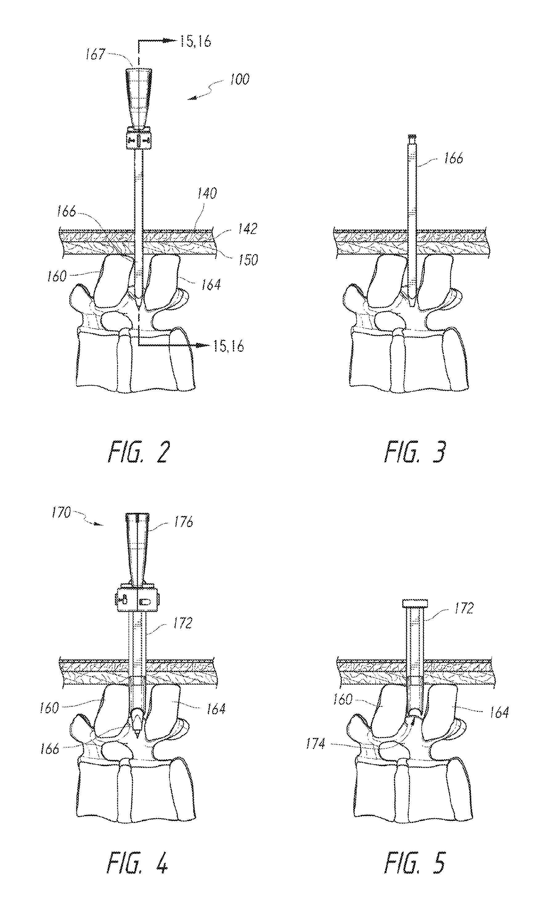
FIGS. 2-5 illustrate a dilation procedure performed using the dilation system 90 of FIG. 1. FIG. 2 shows the introducer dilation assembly 100 after it has been driven into the subject. The introducer dilation assembly 100 can extend through a subject's skin 140, subcutaneous tissue 142, and supraspinous ligament 150 and, in midline procedures, can be positioned generally between adjacent spinous processes 160, 164. FIG. 3 shows the introducer dilator 166 after the needle device 167 (FIG. 2) has been removed therefrom. FIG. 4 shows the dilation assembly 170 after it has been delivered over the introducer dilator 166 to position the instrument cannula 172 between the spinous processes 160, 164. FIG. 5 shows the instrument cannula 172 after the introducer dilator 166 has been removed from the dilation assembly 170 and after the dilator device 176 has been pulled out of the instrument cannula 172. The cannula 172 can hold apart the spinous processes 160, 164 to maintain a desired amount of distraction for enlarging an interspinous space.
FIGS. 6 and 7 illustrate a method of performing at least a portion of the decompression procedure using the instrument cannula 172 held by a cannula holder 173. A surgical instrument in the form of a reamer instrument 190 has a distal end 192 that can scrape, abrade, or otherwise alter tissue within, adjacent to, or along the subject's spine. Other instruments can be delivered through the cannula 172 to perform a wide range of decompression procedures or other type of procedure. Details of the instruments and features shown in FIGS. 1-7 are discussed below.
FIG. 8 is an isometric view of the introducer dilation assembly 100 with a relatively sharp tip or distal portion 200. FIG. 9 is an exploded isometric view of the introducer dilation assembly 100. The needle device 167 can include a handle 210, a locking mechanism 212, and a needle 214. The handle 210 can be conveniently gripped by a user to push the introducer dilation assembly 100 into the subject. The locking mechanism 212 can have a locked configuration for holding the introducer dilator 166 and an unlocked configuration for releasing the introducer dilator 166. Referring now to FIG. 9, the needle 214 can be directly or indirectly coupled to the handle 210 and can include an elongate body 220 and a distal portion 222 with a sharp needle tip 202. To assemble the introducer dilation assembly 100, the needle tip 202 can be inserted into the introducer dilator 166. The needle 214 can be advanced along the introducer dilator 166 until a proximal end 240 of the introducer dilator 166 is received by the locking mechanism 212. The locking mechanism 212 can be moved from an unlocked configuration to a locked configuration to securely hold the introducer dilator 166. Details of the introducer dilator 166 are discussed in connection with FIGS. 10-12, details of the needle device 167 are discussed in connection with FIGS. 13 and 14, and details of the locking mechanism 212 are discussed in connection with FIGS. 15 and 16.
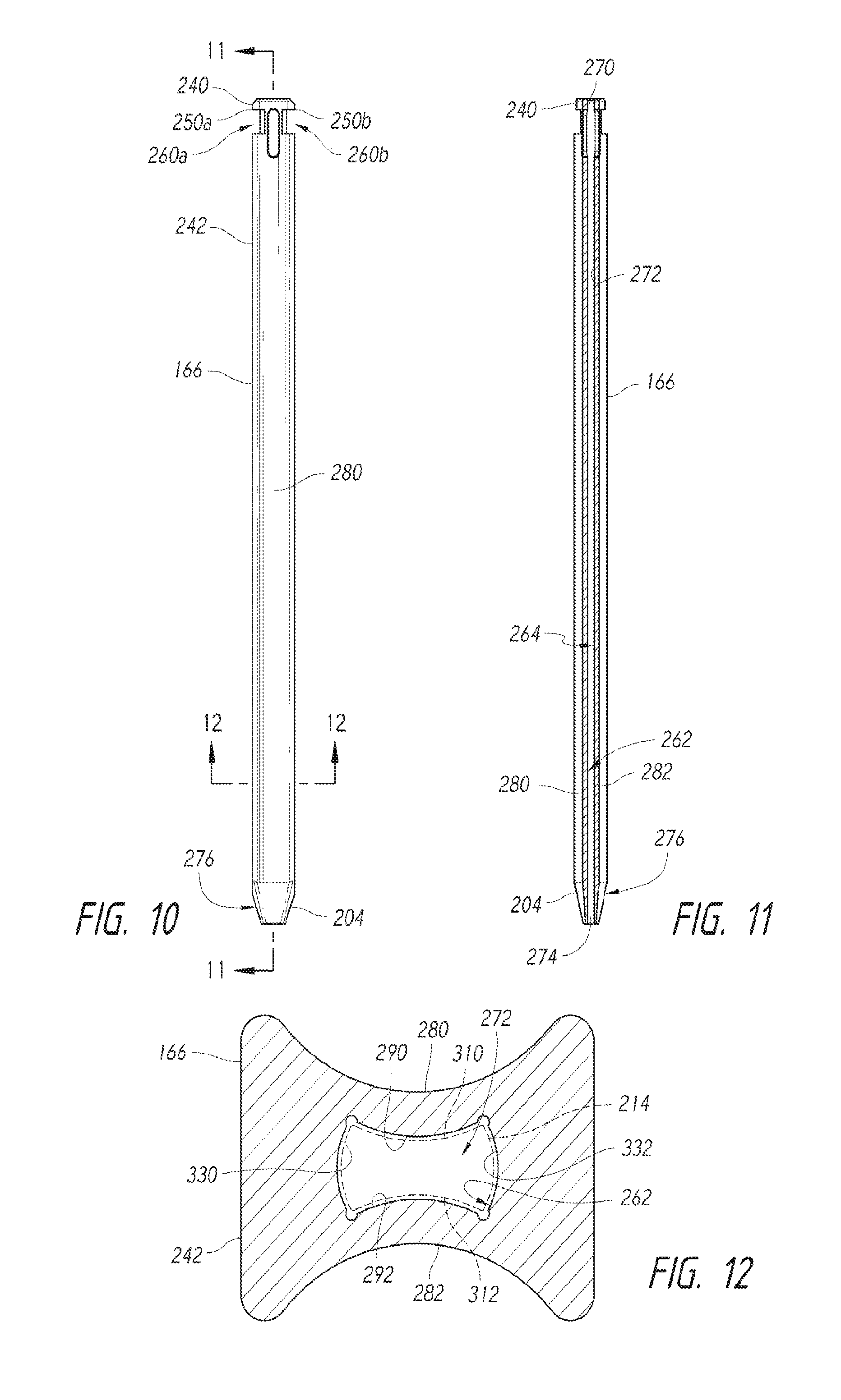
FIG. 10 is a front view of the introducer dilator 166 in accordance with an embodiment of the present disclosure. FIG. 11 is a longitudinal cross-sectional view of the introducer dilator 166 taken along line 11-11 of FIG. 10. FIG. 12 is a cross-sectional view of the introducer dilator 166 taken along line 12-12 of FIG. 10. Referring now to FIG. 10, the introducer dilator 166 can include a tapered distal end 204, proximal end 240, and main body 242. The distal end 204 can include an opening 274 (FIG. 11) and a smooth outer surface 276 and can have a generally frusto-conical shape, truncated pyramidal shape, or other shape suitable for passing through an incision, spreading or stretching tissue, dilating openings or gaps, or the like. The proximal end 240 can include flanges 250a, 250a that define receiving windows 260a, 260b, respectively. Referring now to FIGS. 11 and 12, an inner surface 262 defines a passageway 272 extending between the openings 270, 274. The passageway 272 is configured to slidably receive the needle 214 (FIG. 9).
FIG. 12 shows two oppositely positioned outer alignment features in the form outer channels 280, 282 that extend longitudinally along the main body 242. The channels 280, 282 can have U-shaped profiles, V-shaped profiles, arcuate profiles (e.g., concave configurations), or other profiles suitable for engaging vertebrae, spinous processes, or other tissue. As shown in FIG. 10, the channel 280 can extend from the distal end 204 toward the proximal end 240 to allow tissue to slide along the entire length of the introducer dilator 166 or portion thereof. Inner alignment features 290, 292 can be in the form of longitudinally-extending convex portions located on opposites sides of the passageway 272. The number, location, and orientation of alignment features can be selected based on the instruments used with the introducer dilator 166.
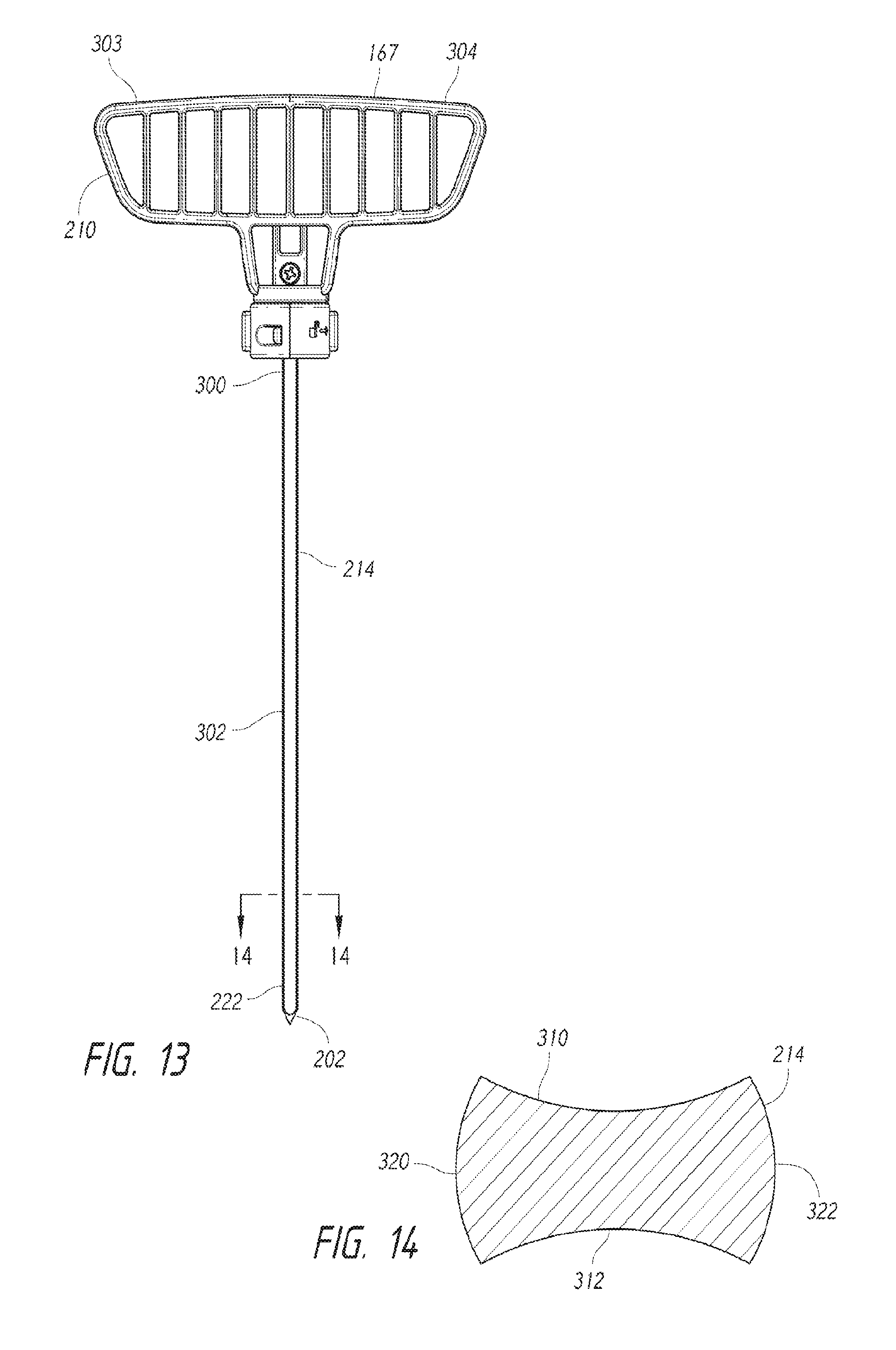
FIG. 13 is a front view of the needle device 167 in accordance with an embodiment of the disclosure. The needle 214 can include the needle tip 202, a proximal end 300, and a main body 302. The proximal end 300 can be fixedly or detachably coupled to the handle 210, illustrated as a T-shaped handle that a user can comfortably grip by wrapping his or her fingers about handle end portions 303, 304. Other types of handles can also be used. The needle tip 202 may be relatively sharp and may have a knife-like edge that can pierce tissue (e.g., ligaments) without first using a sharp edge and can therefore be used for percutaneous procedures. In other embodiments, the needle tip 202 can have a conical shape, a pyramidal shape, or other suitable shape for piercing tissue.
FIG. 14 is a cross-sectional view of the needle 214 taken along line 14-14 of FIG. 13. Two oppositely positioned alignment features in the form of channels 310, 312 extend longitudinally along the main body 302. Referring to FIG. 13, the channels 310, 312 can have arcuate profiles, U-shaped profiles, V-shaped profiles, or other suitable convex or concave profiles for engaging the alignment features 290, 292 (FIG. 12) of the introducer dilator 166. In some embodiments, the channels 310, 312 can slidably engage respective alignment features 290, 292 of the introducer dilator 166 to rotationally lock together the needle 214 and introducer dilator 166. Alignment features in the form of longitudinally-extending convex portions 320, 322 located on opposites sides of the needle 214 can slidably engage alignment features in the form of convex portions 330, 332 (FIG. 12). In various embodiments, the needle 214 can have a polygonal cross-sectional profile (e.g. a square profile, a rectangular profile, etc.), an elliptical profile, or other profile suitable for maintaining desired alignment with introducer dilators or other components.
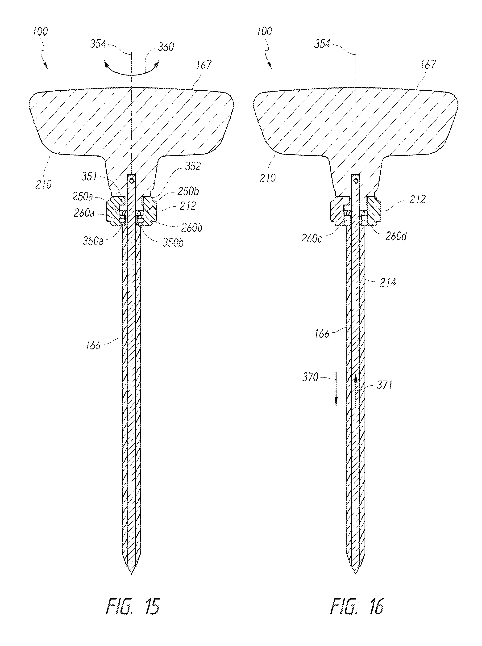
FIGS. 15 and 16 are longitudinal cross-sectional views of the introducer dilation assembly 100 with the locking mechanism 212 in locked and unlocked configurations, respectively. Referring to FIG. 15, flanges 250a, 250b of the introducer dilator 166 can be held between upper surfaces of the retaining elements in the form of flanges 350a, 350b and an abutment 351 of the handle 210. To move the locking mechanism 212 to the unlocked configuration, a cylindrical body 352 of the locking mechanism 212 can be rotated about an axis of rotation 354 (indicated by arrows 360) to move the flanges 350a, 350b. FIG. 16 shows the locking mechanism 212 in the unlocked configuration after the flanges 350a, 350b (FIG. 15) have been moved out of the windows 260a, 260b. To separate the introducer dilator 166 and the needle device 167, the user can push the introducer dilator 166 distally (indicated by arrow 370) away from the handle 210 and/or pull the needle 214 proximally (indicated by arrow 371) relative to the introducer dilator 166. Other types of locking mechanisms can be used and may include, without limitation, one or more pins, threaded members, or other features suitable for coupling together and releasing components.
FIG. 17 is an isometric view of the outer dilation assembly 170 in accordance with an embodiment of the disclosure. FIG. 18 is an exploded isometric view of the outer dilation assembly 170. Referring to FIGS. 17 and 18 together, the dilator device 176 can include a dilator handle 400, a locking mechanism 412, and an elongate dilator 402 with a distal end 410. The locking mechanism 412 has a locked configuration for coupling together the instrument cannula 172 and the dilator device 176 and an unlocked configuration for separating the instrument cannula 172 and the dilator device 176.
To assemble the outer dilation assembly 170 of FIG. 18, the distal end 410 of the elongate dilator 402 can be inserted into an entrance opening 420 of the instrument cannula 172. The elongate dilator 402 can be moved along the cannula 172 until a head 430 of the cannula 172 is received by the locking mechanism 412. The locking mechanism 412 can be moved from the unlocked configuration to a locked configuration to hold together the dilation assembly 170 and instrument cannula 172 such that the distal end 410 protrudes from the instrument cannula 172 to expose sloped channels 442.
FIG. 19A is an isometric view of the instrument cannula 172 in accordance with an embodiment of the disclosure. FIG. 19B is a cross-sectional view of the instrument cannula 172 taken along line 19B-19B of FIG. 19C. FIG. 19C is a bottom view of the instrument cannula 172. The instrument cannula 172 can include the head 430, distal end 410, and main body 440 therebetween. The head 430 defines the opening 420 (FIGS. 19A and 19B) and keying features 450a, 450b (collectively "keying features 450"). An instrument passageway 470 (FIG. 19B) extends between the opening 420 and the opening 472 and is configured to receive instruments.
The instrument cannula 172 can include positioning features 460 located along the bottom of guide channels 480. The positioning features 460 can be recesses (e.g., spherical recesses, elongated recesses, etc.), protrusions, grooves, notches, or other features suitable for engaging tissue or bone. The illustrated embodiment includes eleven positioning features 460, but a greater or lesser number of positioning features can be selected based on a desired number of available preferential positions. In some embodiments, the instrument cannula 172 can include an array of locators 461 for positioning relative to a holder, such as the clamp assembly discussed in connection with FIGS. 37-42. The guide channels 480 can have U-shaped cross-sectional profiles, V-shaped cross-sectional profiles, or other suitable profiles for interacting with anatomical features. The guide channels 480 can be sloped or angled to provide for distraction.
FIG. 20A is an isometric view of an instrument cannula in accordance with an embodiment of the disclosure. FIG. 20B is a cross-sectional view of the instrument cannula taken along line 20B-20B of FIG. 20C. FIG. 20C is a bottom view of the instrument cannula of FIG. 20A. The description of the cannula 172 of FIGS. 19A-19C applies equally to the cannula 172 of FIGS. 20A-20C, except as detailed below. The cannula 172 has twelve (illustrated), thirteen, fourteen, or more positioning features 460 located along a central region of the guide channels 480. Guide rails 481 of FIGS. 20A and 20B are higher and longer than guide rails 481 of FIG. 19C. In some embodiments, most or all of the positioning features 460 of FIGS. 20A-20C are positioned between the guide rails 481. The number, spacing, dimensions of the positioning features 460 can be selected based on the positions and configurations of the anatomical structures to be received, and the spacing and dimensions (e.g., lengths, heights, etc.) of the guide rails 481 can be selected based on the anatomical features to be moved along the guide channels 480.
FIG. 21A is an isometric view of an instrument cannula 172 in accordance with an embodiment of the disclosure. FIG. 21B is a cross-sectional view of the instrument cannula taken along line 21B-21B of FIG. 21C. FIG. 21C is a bottom view of the instrument cannula of FIG. 21A. The description of the cannula 172 of FIGS. 19A-20C applies equally to the cannula 172 of FIGS. 21A-21C, except as detailed below. Referring to FIG. 21A, the cannula 172 has positioning features (illustrated as notches) located along the guide channels. Instruments can be passed through access features 487 circumferentially spaced about the cannula 172. The access features 487 can be ports, through-holes, or other features through which visualization instruments, surgical instruments, or other instruments can be passed. For example, illumination instruments can be inserted through the ports 487 to illuminate tissue distal to the cannula 172.
FIGS. 22 and 23 are side and bottom views, respectively, of the dilator device 176. Referring to FIG. 22, the handle 400 can include handle portions 500a, 500b, a guide 530, and an access opening or window 502 between the handle portions 500a, 500b. The guide 530 can include an opening 532 (FIGS. 17 and 24) positioned generally along the longitudinal axis 541 of the dilator device 176. Other types of handle assemblies can also be used. For example, T-shaped handles or spherical shaped handles can be used, if needed or desired.
FIGS. 24 and 25 are cross-sectional views of the dilator device 176 holding the introducer dilator 166 (shown in phantom line). The elongate dilator 402 can include the distal end 410, a proximal end 540, and an elongate body 544 therebetween. A passageway 545 extends between openings 546, 547. FIG. 24 shows the locking mechanism 412 in a locked configuration for coupling together the instrument cannula 172 and outer dilation assembly 170. The head 430 of the instrument cannula 172 can be held between retaining features 550a, 550b of the locking mechanism 412 and an abutment 553 of the handle 400. A main body 572 of the locking mechanism 412 can be rotated about an axis of rotation 574 (indicated by arrows 552) until the retaining features 550a, 550b are aligned with the keying features (e.g., keying features 450a, 450b of FIGS. 19A-19B of the head 430). FIG. 25 shows the locking mechanism 412 in the unlocked configuration to align the retaining features 550a, 550b with the keying features 450a, 450b, respectively. As such, the instrument cannula 172 is free to slide distally along the elongate dilator 402 away from the locking mechanism 412.
FIG. 26 is an isometric view of a reamer instrument 190 in accordance with an embodiment of the disclosure. FIG. 27 is an isometric view of the reamer instrument 190 with a retracted reaming tip and an extended depth stop member 650. Referring now to FIG. 26, the reamer instrument 190 can include a reaming assembly 600 for abrading, scraping, or otherwise mechanically altering bone or tissue and a handle assembly 602 for operating the reaming assembly 600. The reaming assembly 600 can include a reaming tip 611 for contacting distal tissue and a lateral reaming element 612 for contacting lateral tissue. The reaming tips 611, 612 can include a roughened surface, array of sharp protrusions, texturing, or other features capable of loosening, separating, cutting, scraping, or otherwise affecting tissue. For example, the reaming tip 611 can be used to bore through tissue, and the lateral reaming element 612 can be used to ream laterally adjacent tissue. When the tip reaming tip 611 is retracted to an atraumatic position (FIG. 27), it can be positioned inside of the lateral reaming element 612. As shown in FIG. 27, an atraumatic edge 613 can be configured to inhibit or prevent injury to distal tissue. Accordingly, the reaming assembly 600 can be moved between different configurations to target specific tissue during a procedure.
The handle assembly 602 can include, without limitation, a depth stop mechanism 630, a reaming control element 632 ("control element 632"), and a handle housing 640 for protecting internal components. The depth stop mechanism 630 can include the stop member 650 and a positioning assembly 652. The stop member 650 can include a head 653 oriented generally perpendicular to a longitudinal axis 655 of the reaming assembly 600. The positioning assembly 652 can be used to move the stop member 650 distally (indicated by arrow 660 in FIG. 26) or proximally (indicated by arrow 661 in FIG. 27) to adjust, for example, a maximum depth of penetration of the reaming assembly 600. Once the stop member 650 is at the desired location, the positioning assembly 652 can be locked to hold the head 653 stationary relative to the reaming assembly 600. The reaming control element 632 can be moved proximally (indicated by arrow 670 in FIG. 26) to move the reaming tip 611 (FIG. 26) into the lateral reaming element 612. Referring now to FIG. 27, the reaming control element 632 can be moved distally (indicated by arrow 672) to move the reaming tip 611 out of the lateral reaming element 612.
FIG. 28 is a longitudinal cross-sectional view of the reamer instrument 190. In one embodiment, the reaming assembly 600 can include an outer reamer member 610 with the lateral reaming element 612 and an inner reamer member 750 with the reaming tip 611. The outer reamer member 610 can have a proximal end 720, a distal end 722, and a hollow elongate main body 724. The proximal end 720 can be fixedly coupled to the handle housing 640. The main body 724 can be a shaft (e.g., a tubular shaft made of metal, plastic, etc.) with an inner surface 740 (FIG. 29) that closely surrounds the inner reamer member 750. The inner reamer member 750 can include a proximal end 752, a distal end 754, and an elongate body 756 (e.g., a solid or hollow rod or shaft made of metal, plastic, etc.). The proximal end 752 can be connected to the control element 632 by, for example, one or more fasteners, pins, welds, or other connection elements. In other embodiments, the proximal end 752 and a control element 632 can have a one-piece construction.
FIGS. 29 and 30 are detailed cross-sectional views of the distal end of the reaming assembly 600 in two different configurations. Referring now to FIG. 29, the distal end 722 of the outer reamer member 610 can include an opening 732 and a stop in the form of a shoulder 734. A widened passageway 730 extends from the opening 732 to the shoulder 734. The distal end 754 of the inner reamer member 750 can include a shoulder 763 and a head 762. FIG. 29 shows the reaming tip 611 in a distal reaming position such that the reaming tip 611 protrudes outwardly (distally) from the edge 613 of the distal end 722. The inner reamer member 750 can be moved proximally (indicated by arrow 770 in FIG. 29) until the shoulder 763 contacts the shoulder 734 (FIG. 30).
Referring again to FIG. 7, the deployed reaming tip 611 can be used to abrade tissue (not shown) located posterior to the illustrated ligamentum flavum 615. The reaming assembly can be advanced distally to abrade tissue adjacent to the ligamentum flavum 615 or the tissue of the ligamentum flavum 615. The reaming tip 611 can be retracted to the atraumatic position (FIGS. 27 and 30) to avoid damaging non-targeted tissue, such as the spinal cord 617, which is located between the ligamentum flavum 615 and a ligament 184. The spinal cord 617 extends from the brain to the bottom of the spine and extends through vertebral foramina. Spinal nerves branch from the spinal cord 617 and exit the spine and extend to other parts of the body. The reaming tip 611 can be retracted to avoid traumatizing or damaging nerve tissue, or other non-targeted tissue, such as the epidural sac. With the reaming tip 611, the reamer instrument 190 can be inserted deeper into the subject without risk of tearing or damaging the epidural sac or injuring the spinal cord 617. For example, the atraumatic edge 782 (FIG. 30) can be blunted, rounded, and/or smooth to inhibit, limit, or substantially prevent damage and/or injury to the epidural sac.
Referring again to FIG. 28, the depth stop mechanism 630 can include a control element 700, a slider locking element 702, and a rack 704. The control element 700 can include a cantilevered lever 709 movable between a first position (e.g. an undepressed position, an extended position, etc.) to a second position (e.g., a depressed position, an unextended position, etc.). When the control element 700 is depressed, an engagement feature (e.g., a U-shaped member) can be moved away from teeth of the rack 704. To move the positioning assembly 630 from a locked configuration (FIG. 28) to an unlocked configuration, a user can press down on the control element 700 to overcome a biasing force provided by the element 709 and thereby move the control element 700 downwardly. After the control element 700 is depressed, it can be moved proximally or distally. After the stop member 650 is moved to the desired position, the control element 700 can be released to allow the control element 700 to move back to the undepressed position. Other types of positioning assemblies can be used and can include, without limitation, one or more biasing devices (e.g. springs, actuators, etc.), control elements, gears, or the like. The configuration and functionality of the positioning assemblies can be selected based on the desired operation of the reamer instrument 190.
FIGS. 31-35 illustrate a method of performing at least a portion of a decompression procedure on a patient in accordance with an embodiment of disclosure. Generally, an incision can be made along the patient's back using, for example, a scalpel 780. The introducer dilation assembly 100 can be moved through the incision and inserted between the spinous processes 160, 164. The needle device 167 can be removed from the introducer dilator 166. The dilation assembly 170 can be advanced over the introducer dilator 166 and into the subject. The introducer dilator 166 can then be removed from the dilation assembly 170, and the dilator device 176 can then be removed from the instrument cannula 172. Details of the procedure are discussed below.
FIG. 31 shows the scalpel 780 ready to make an incision along the midline of the subject. An entry point can be selected on the patient's skin to obtain access to the targeted surgical site, and an incision of appropriate length is made through the dermal layers of a patient's body at the entry point. The length and depth of the incision may be larger depending on whether the clinician is using an open, mini-open, or minimally invasive, percutaneous approach. In some procedures, a targeted surgical level can be identified and a midline incision (e.g., 5 mm to 15 mm length incision) can be made under direct visualization, fluoroscopic guidance, or other suitable visualization technique. In some procedures, the supraspinous ligament 150 can be dissected (e.g., longitudinally dissected) to provide access to an interspinous space 174. The scalpel 780, or other cutting instruments, can form incisions at other locations to access the spine using non-midline approaches, such as lateral approaches.
FIG. 32 shows the introducer dilation assembly 100 after it has been passed through the incision and moved through the supraspinous ligament 150. As the introducer dilation assembly 100 is advanced distally, the sharp tip 202 and distal end 204 dilates tissue (e.g., spreads or separates tissue) and/or otherwise affect tissue to facilitate penetration into the patient. As the introducer dilation assembly 100 is initially inserted between the spinous processes 160, 164, it can drive apart the spinous processes. The distracted spinous processes 160, 164 can be positioned in and slide along the channels 280, 282, respectively, (FIG. 12) until the distal end 204 is at the desired depth. The spinous processes 160, 164 in the channels 280, 282, respectively, can inhibit or limit rotation of the introducer dilator 166. Such placement of the introducer dilation assembly 100 with respect to the spinous processes 160, 164 therefore stabilizes the introducer dilation assembly 100.
The introducer dilation assembly 100 can be monitored using fluoroscopy, direct visualization, or other visualization technique. After the introducer dilation assembly 100 is at the desired location, the locking mechanism 212 can be moved from the locked configuration to the unlocked configuration and the needle device 167 can then be pulled out of the introducer dilator 166.
FIG. 33 shows the needle device 167 separated from the introducer dilator 166. A longitudinal axis 781 of the introducer dilator 166 can be generally perpendicular to the patient's spine or at another suitable orientation. For example, the longitudinal axis 781 can be generally parallel to the anterior-to-posterior direction.
Referring to FIG. 34, the dilation assembly 170 has been inserted over the introducer dilator 166. The dilation assembly 170 can be aligned (e.g., rotationally aligned) with the proximal end 240 of the introducer dilator 166 and then slid over the proximal end 240. As shown in FIG. 23, the alignment features 560, 562 (e.g., convex features) of the elongate dilator 402 can be received by the channels 280, 282 of the introducer dilator 166 to rotationally lock the dilator 402 and the introducer dilator 166. As the dilator 402 moves along the introducer dilator 166, the tapered distal end (FIG. 17) can dilate the incision, spread or separate tissue, and/or otherwise affect tissue to facilitate penetration into the patient. If the spinous processes 160, 164 are sufficiently close together, the distal end 410 can contact and push apart the spinous processes 160, 164.
As the dilation assembly 170 is advanced over the introducer dilator 166, the channels 280, 282 (FIG. 12) of the introducer dilator 166 can be aligned with the respective alignment features 560, 562 (FIG. 23). The spinous processes and/or tissue can move from the channels 280, 282 of the dilator 166 to the respective alignment features 560, 562 of the dilator 402 as the dilation assembly 170 is advanced along the stationary dilator 166. Referring to FIGS. 21 and 34, the channels 480 of the cannula 172 (FIG. 21) can be generally aligned with the channels 442 (FIG. 17) of the elongate dilator 402 such that the spinous processes and/or tissue move from the channels 442 of the dilator 402 to the respective channels 480 of the cannula 172.
FIG. 35 shows the dilator device 176 spaced apart from the instrument cannula 172. FIG. 36 shows an instrument cannula 172 positioned between the spinous processes 160, 164. Tips of the spinous processes 160, 164 can be received by the receiving features 460 (see, e.g., FIG. 19A) to set the cannula 172. Any number of different instruments can be delivered through the instrument cannula 172 to treat a wide range of symptoms, conditions, and/or diseases, including, without limitation, spinal nerve compression (e.g., spinal cord compression, spinal nerve root compression, or the like), spinal disk herniation, osteoporosis, stenosis, or other diseases or conditions. In some procedures, the cannula 172 provides access for surgical instruments for performing a spinal cord decompression procedure that includes, without limitation, delivering visualization media, removing bone from one or both vertebrae 804, 806, separating the ligamentum flavum from one or both vertebrae 804, 806, cutting or debulking the ligamentum flavum, and removing loose tissue. A wide range of decompression procedures can be performed and can include, without limitation, a discectomy, osteophyte removal, laminotomy, or other type of decompression procedures for removing bone and/or soft tissue. Each stage of the decompression procedure can be performed with a different instrument or series of instruments.
Instruments can be advanced through the cannula 172 to remove tissue (e.g., bone, connective tissue, etc.) to, for example, reduce spinal compression, increase access to the treatment site, and can be viewed under fluoroscopy or other suitable visualization technique. The cannula 172 can be sufficiently large to allow repositioning of the instruments to access different treatment sites, such as the lateral recesses, facets, ligamentum flavum, or the like. In some simultaneous bilateral access procedures, the cannula 172 can be repositioned while remaining in the patient to remove tissue from opposing lateral recesses or other lateral treatment sites. Additionally, the cannula 172 can provide direct visualization. For example, a user can view the treatment site and/or instrument by looking through the passageway of the cannula 172. Additionally or alternatively, visualization devices (e.g., fiber optics, cameras, light sources, or the like) can be coupled to or incorporated into the cannula 172. After removing the desired amount of bone (or other tissue), the instrument can be withdrawn from the subject.
Fluoroscopy (e.g., anterior-posterior imaging, lateral imaging, contralateral-oblique imaging, etc.) can be used to view the treatment site, tools, and delivery path. In certain procedures, visualization techniques can be used to identify margins of the epidural space, dura, ligamentum flavum, and/or nerve roots relative to the lamina and interlaminar space, as well as the features of instruments. Contrast media can be refreshed to maintain desired imaging. When reaming instruments (e.g., reaming instrument 190) are near nerve tissue, the reaming instruments can be in an atraumatic configuration.
FIGS. 37-39 illustrate a method of assembling a holder in the form of an instrument positioner assembly for holding an instrument cannula in accordance with an embodiment of the disclosure. Generally, the cannula 172 can be installed in a collar 800 positionable in an open clamp assembly 802. The cannula 172 can be rotated relative to the clamp assembly 802. After the cannula 172 is at the desired orientation, the clamp assembly 802 can be closed to securely hold the collar 800. Instruments can be delivered through the cannula 172 while the clamp assembly 802 holds the cannula 172 at the desired orientation. The clamp assembly 802 can be opened to reorient the cannula 172. Non-limiting exemplary methods of using the clamp assembly 802 are discussed below.
A user can select a desired axial position along the cannula 172 for the collar 800 based on, for example, the distance from the patient's skin to the treatment site. FIG. 37 shows the collar 800 coupled to the cannula 172 and ready for installation in the clamp assembly 802. The collar 800 can include protrusions or other features matable with one or more locators 461 of the cannula 172. The illustrated cannula 172 includes an array of spaced apart locators 461 that can be, for example, recess, holes, or the like. The cannula 172 can be inserted into the patient before or after installing the collar 800.
The clamp assembly 802 can be placed over the collar 800. A base 810 (FIG. 38) can rest against the patient's skin and can extend in the superior direction (or other direction). The cannula 172 can be rotated in the lateral direction (indicated by arrows 812, 814) or other desired direction. The base 810 can inhibit or limit rocking movement of the clamp assembly 802 (e.g., rocking in the superior direction), thereby stabilizing the cannula 172.
Referring to FIG. 38, a lever mechanism 816 can be used to close and open the clamp assembly 802. FIG. 39 shows the closed clamp assembly 802 with the rotationally fixed collar 800. The cannula 172 can be keyed to the collar 800 to prevent axial movement of the cannula 172, and the clamp assembly 802 can be opened to adjust the orientation of the cannula 172. When an instrument is positioned in the cannula 172, a depth stop mechanism of the instrument can contact the cannula 172 to limit movement of the instrument in the distal direction. By way of example, the stop member 650 discussed in connection with FIGS. 26-27 can contact the proximal end (e.g., head 430) of the cannula 172 and thereby limit the penetration depth of the reamer instrument 190. By adjusting the position of the stop member 650 (FIGS. 26-27), the penetration depth of the reamer instrument 190 can be adjusted to safely access targeted tissue.
FIGS. 40-42 illustrate the clamp assembly 802 positioned on a patient. The cannula 172 of FIG. 40 is positioned to access left regions of the subject's left lateral vertebrae recess of a vertebral body. The cannula 172 of FIG. 41 is positioned to access the right regions of the subject's right lateral recess of the vertebral body. FIG. 42 shows the reamer instrument 190 ready to be delivered through the cannula 172. Visualization techniques can be used to confirm the position, trajectory, and depth of the end of instrument cannula 172, instrument(s), etc. The dimensions (e.g., diameter) of the passageway 470 (FIG. 19B) of the cannula 172 can be sufficiently large to allow repositioning of the instrument to access different treatment sites, such as the lateral recesses, facets, ligamentum flavum, or the like. In some simultaneous bilateral access procedures, the cannula 172 can be repositioned while remaining in the patient to remove tissue from opposing lateral recesses or other lateral treatment sites. Additionally, the cannula 172 can provide direct visualization. For example, a user can view the treatment site and/or instrument by looking through the passageway 470 (FIG. 19B). Additionally or alternatively, visualization devices (e.g., fiber optics, cameras, or the like) can be coupled to or incorporated into the cannula 172 and/or instruments for viewing.
In some procedures, the reamer instrument 190 can extend a distance (e.g., 10 mm, 15 mm, 20 mm, etc.) past the distal end of the cannula 172 when the stop member 650 contacts the head 430. The reamer instrument 190 can be rotated to abrade, loosen, tear, or otherwise alter tissue and can be removed any number of times to remove residual tissue (e.g., ligament tissue, bone tissue, etc.) attached to the reamer instrument. Different types of instruments can be used to cut bone, create one or more defects (e.g., a generally hemispherical defect) in the inferior medial aspect of the superior lamina, or otherwise prepare the treatment site.
To remove midline tissue, the cannula 172 can be oriented towards the midline interlaminar region. A reamer instrument can be inserted through the cannula 172 and positioned towards the midline position of the superior lamina. In one exemplary embodiment, the depth stop mechanism 630 of the reamer instrument 190 can be used to, for example, prevent injury to the dural or other non-targeted tissue. Visualization techniques can be used to monitor the position on the reamer head. In some procedures, the reamer head can be moved from midline to left lateral or the right lateral. Any number of reamer instruments can be used to remove the desired amount of midline lamina bone. The depth stop mechanism can be used to allow access to the targeted region while maintaining a desired distance from the epidural space and other vital structures. After performing the reaming procedure, the reamer can be removed from the patient and a preparation procedure can be performed. The preparation procedure can include, without limitation, irrigating the treatment site, removing residual tissue (e.g., via suction), applying one or more agents (e.g., hemostatic agents), or other procedures.
A debulker instrument can be used to provide a complete blunt dissection of the ligamentum flavum from the lamina and disrupt ligamentous tissue. In some procedures, the debulker instrument is inserted through the cannulas and positioned at a midline position of the superior lamina. The depth stop mechanisms can facilitate positioning of the distal tip (e.g., debulking head) at the most dorsal margin of the superior lamina. Intraoperative fluoroscopy and/or tactile feedback can be used to confirm positioning. While maintaining a midline trajectory, the distal tip of the debulker instrument can be gently moved around the inferior lamina lip and repositioned against the bony underside. The adjustable depth stop can be reset, if desired, to allow access to the targeted region while maintaining a desired distance from the epidural space and other vital structures. The properly positioned distal tip can engage the underside of the lamina and resist attempts to gently withdraw the instrument.
The debulking tip can dissect and separate the ligamentum flavum from the lamina when it is move from midline toward the lateral recess. A subtle left-right sweeping motion can be used disrupt ligamentous tissue and help extend the desired tissue plane. The distal tip can be moved until it reaches the most lateral desired position. The depth stop mechanism can be adjusted to allow access to the lateral recesses. The debulker tip can be moved slightly inferior and out from the lamina underside. The debulker tip can be used to continually debulk the ligamentum flavum. The depth stop mechanism can be adjusted to allow access to the targeted region, while intraoperative fluoroscopy is used to verify the distal tip position and maintain a safe working distance from the epidural space and/or other vital structures. After performing the debulking procedure, the debulker instrument can be removed from the patient and a preparation procedure can be performed.
The lamina can be removed using a tissue removal instrument. The cannula 172 can be oriented towards the desired interlaminar region (e.g., left or right interlaminar region). A closed jaw assembly of a tissue removal instrument can be moved through the cannula 172 towards a generally midline position. A depth stop mechanism can be used to adjust the depth of penetration until the jaw assembly is positioned proximate the most dorsal margin of the superior lamina. The jaw assembly can be closed to remove tissue. While maintaining midline trajectory, the jaw assembly can be moved around the inferior lamina lip and positioned against the bony underside. The depth stop can be adjusted to allow access to the targeted region while maintaining a desired distance from the epidural space and other vital structures. The distal or lower jaw of the jaw assembly can engage the underside of the lamina and the proximal or upper jaw can be positioned just dorsal to the lamina. The jaw assembly can be held against the targeted lamina bone while the jaw assembly is closed. The tissue removal instrument can be withdrawn from the patient. The jaw assembly can be opened to release the captured material. This process can be repeated to remove bone and other tissue in the lateral direction until the desired decompression is achieved.
Systems, components, and instruments disclosed herein can be disposable or reusable. For example, the reamer instrument 190 can be disposable to prevent cross-contamination. As used herein, the term "disposable" when applied to a system or component (or combination of components), such as an instrument, a tool, or a distal tip or a head (e.g., a reamer head, a jaw assembly, etc.), is a broad term and generally means, without limitation, that the system or component in question is used a finite number of times and is then discarded. Some disposable components are used only once and are then discarded. In other embodiments, the components and instruments are non-disposable and can be used any number of times.
The cannula 172 can be used deliver one or more spinal implants before, after, or during tissue removal. The methods of delivery, delivery instruments, dilators, spinal implants, and other features of U.S. Pat. Nos. 8,012,207; 8,123,807; 8,152,837; U.S. application Ser. No. 12/217,662 (corresponding U.S. Pub. No. 20080287997); U.S. application Ser. No. 13/844,173; U.S. application Ser. No. 12/358,010, and U.S. application Ser. No. 13/844,324. U.S. Pat. Nos. 8,012,207; 8,123,807; 8,152,837; U.S. application Ser. No. 12/217,662 (corresponding U.S. Pub. No. 20080287997); U.S. application Ser. No. 13/844,173; U.S. application Ser. No. 12/358,010, and U.S. application Ser. No. 13/844,324 are hereby incorporated by reference in their entireties. FIG. 43 shows an implanted device 830 positioned between the spinous processes 160, 164. The device 830 can be delivered via the cannula or other access device. In one embodiment, the device 830 is a SUPERION.RTM. Interspinous Spacer from VertiFlex, Inc. (San Clemente, Calif.) or a similar device. The device 830 can be implanted while imaging using visualization media and/or direct visualization.
C. Visualization Systems and Procedures
Visualization can be used throughout an entire decompression procedures or stage(s) of decompression procedures. Visualization systems and components disclosed herein can be incorporated into or used with dilation systems, introducer dilation assemblies, cannula dilation assemblies, instrument cannulas, dilation devices, instrument positioner assemblies, reamer instruments, and other systems and components disclosed herein.
FIG. 44 is a side view of a visualization system 1100 in accordance with one embodiment of the disclosure. The visualization system 1100 can include an illumination instrument 1110 and an access device in the form of a cannula 1120. The cannula 1120 can be similar or identical to the cannula 172 discussed in connection with FIGS. 21A-21C. The cannula 1120 of FIG. 44 can extend through a subject's skin, subcutaneous tissue, and/or a supraspinal ligament. The illumination instrument 1110 can extend through a sidewall 1122 of the cannula 1120 and can direct light toward a working space 1130. In some embodiments, the instrument 1110 passes through an access features 1487 and can include a light source 1140 and a waveguide. The light source 1140 can output light suitable for viewing tissue with the naked eye or with an optical aid, such as loupes. The waveguide can include a flexible fiber optic cable (illustrated) configured to deliver the light from the light source 1140 towards the space 1130.
An inner surface 1144 of the cannula 1120 can reflect the light to enhance light delivery to the working space 1130. In some embodiments, the inner surface 1144 can include one or more optically reflective coatings. In other embodiments, the cannula 1120 can include one or more reflective elements (e.g., mirrors) for directing light out an open distal end 1127 of the cannula 1120. The cannula 1120 can have one or more imaging devices 1146 positioned to image the working space 1130, and the imaging devices 1146 can include one or more light sources oriented to illuminate tissue within its field of view.
FIG. 45 is a side view of a visualization system 1200 in accordance with one embodiment of the disclosure. The visualization system 1200 can include an imaging instrument 1210 and a cannula 1220. The imaging instrument 1210 is positioned within a lumen of the cannula 1220 and can provide a field of view for viewing the working space 1130 (including regions of the working space 1130 not viewable by direct viewing). The imaging instrument 1210 can be an endoscope or other imaging device for providing a desired field of view. A coupler 1212 can help keep the imaging instrument 1210 positioned to view the working space 1130 while allowing rotation of the imaging instrument 1210 relative to the cannula 1220. In one embodiment, the imaging instrument 1210 can be rotated 360 degrees to provide complete peripheral viewing of tissue not viewable with the naked eye. The orientation of the field of view can be selected based on the desired peripheral viewing. The imaging instrument 1210 can be a visualization instrument with an endoscope 1216 and a viewing device, such as monitor 1218.
FIG. 46 is a side view of a visualization system 1300 in accordance with one embodiment of the disclosure. The visualization system 1300 can include a visualization instrument 1310 extending through a lumen 1340 of a decompression instrument 1350. The decompression instrument 1350 can be identical or similar to the decompression instrument 190 of FIGS. 26 and 27. A distal end 1342 shown in FIG. 46 can be positioned in the field of view 1344 of the instrument 1310. In some embodiments, the visualization instrument 1310 can include a monitor and an endoscope connected to the monitor. The configuration of the visualization instrument 1310 can be selected based on the configuration of the decompression instrument 1350.
FIG. 47 is a side view of the visualization system 1370 including a monitor 1372 and a visualization instrument 1380 extending through a decompression instrument in the form of a rongeur 1400. The field of view of the visualization instrument 1380 can include at least a portion of the rongeur 1400 to accurately positioning jaws 1402a, 1402b. The configuration and position of the instrument 1380 can be selected to provide viewing of the tissue grabbed by the jaws 1402a, 1402b.
The visualization systems disclosed herein can be utilized with a wide range of different types of decompression instruments. A spinal procedure can be performed while viewing the treatment to help, for example, remove tissue to perform a decompression procedure and avoid damaging non-targeted tissue. For example, viewing can help perform one or more of the steps discussed in connection with FIGS. 2-7 and 31-43. In some procedures, a spinal procedure can be performed without utilizing additional view, such as fluoroscopic viewing. In some embodiments, visualization systems disclosed herein can be used with fluoroscopic viewing or other imaging techniques. The various embodiments described herein may also be combined to provide further embodiments. For example, features from various instruments can be combined with features and methods disclosed in U.S. Pat. Nos. 8,012,207; 8,123,807; 8,152,837, U.S. application Ser. No. 12/217,662 (U.S. Publication No. 2008/0287997), and U.S. application Ser. No. 13/844,324, which are incorporated by reference in their entireties and a part of the present specification. A wide range of visualization instruments and treatment instruments can be used to address a wide range of symptoms, conditions, and/or diseases, including, without limitation, spinal nerve compression (e.g., spinal cord compression, spinal nerve root compression, or the like), spinal disk herniation, osteoporosis, stenosis, or other diseases or conditions.
The above detailed descriptions of embodiments of the technology are not intended to be exhaustive or to limit the technology to the precise form disclosed above. Although specific embodiments of, and examples for, the technology are described above for illustrative purposes, various equivalent modifications are possible within the scope of the technology, as those skilled in the relevant art will recognize. For example, while steps are presented in a given order, alternative embodiments may perform steps in a different order. For example, visualization media can be delivered before, during, or after positioning a cannula (e.g., instrument cannula 172 of FIGS. 19-21). Additionally, the instruments (e.g., tissue removal instruments, reamer instruments, debulker instruments, dilators, syringes, etc.) can have one or more stops (e.g., depth stops) to inhibit or prevent injury or damage to tissue. Additionally or alternatively, the stops can be incorporated into the cannulas (e.g., cannulas or instruments disclosed herein). The various embodiments described herein may also be combined to provide further embodiments. For example, features from various instruments can be combined with features disclosed in U.S. Pat. Nos. 8,012,207; 8,123,807; 8,152,837, U.S. application Ser. No. 12/217,662 (U.S. Publication No. 2008/0287997), and U.S. application Ser. No. 12/358,010, which are hereby incorporated by reference herein and made a part of this application.
Where the context permits, singular or plural terms may also include the plural or singular term, respectively. Moreover, unless the word "or" is expressly limited to mean only a single item exclusive
References
D00000
D00001
D00002
D00003
D00004
D00005
D00006
D00007
D00008
D00009
D00010
D00011
D00012
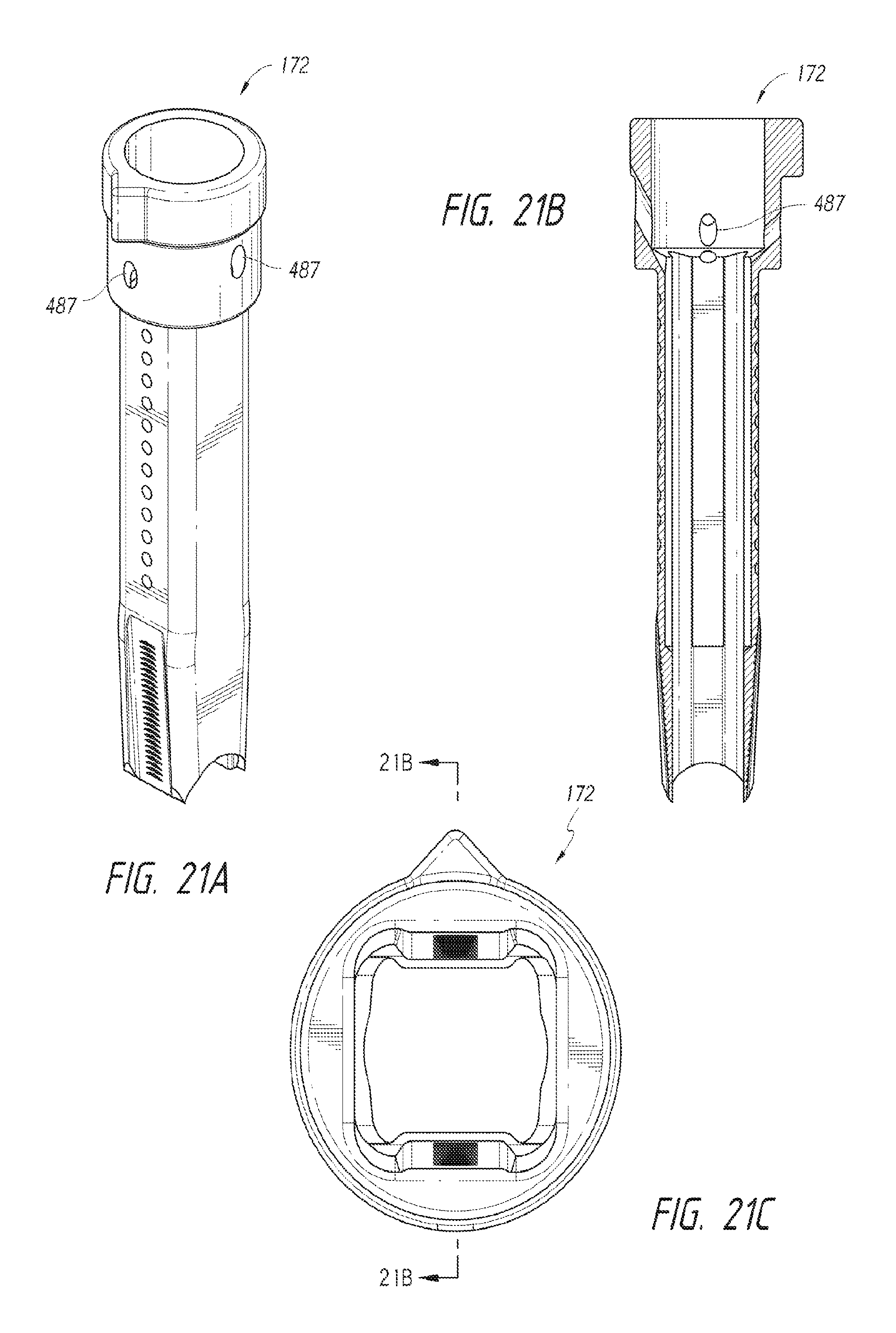
D00013
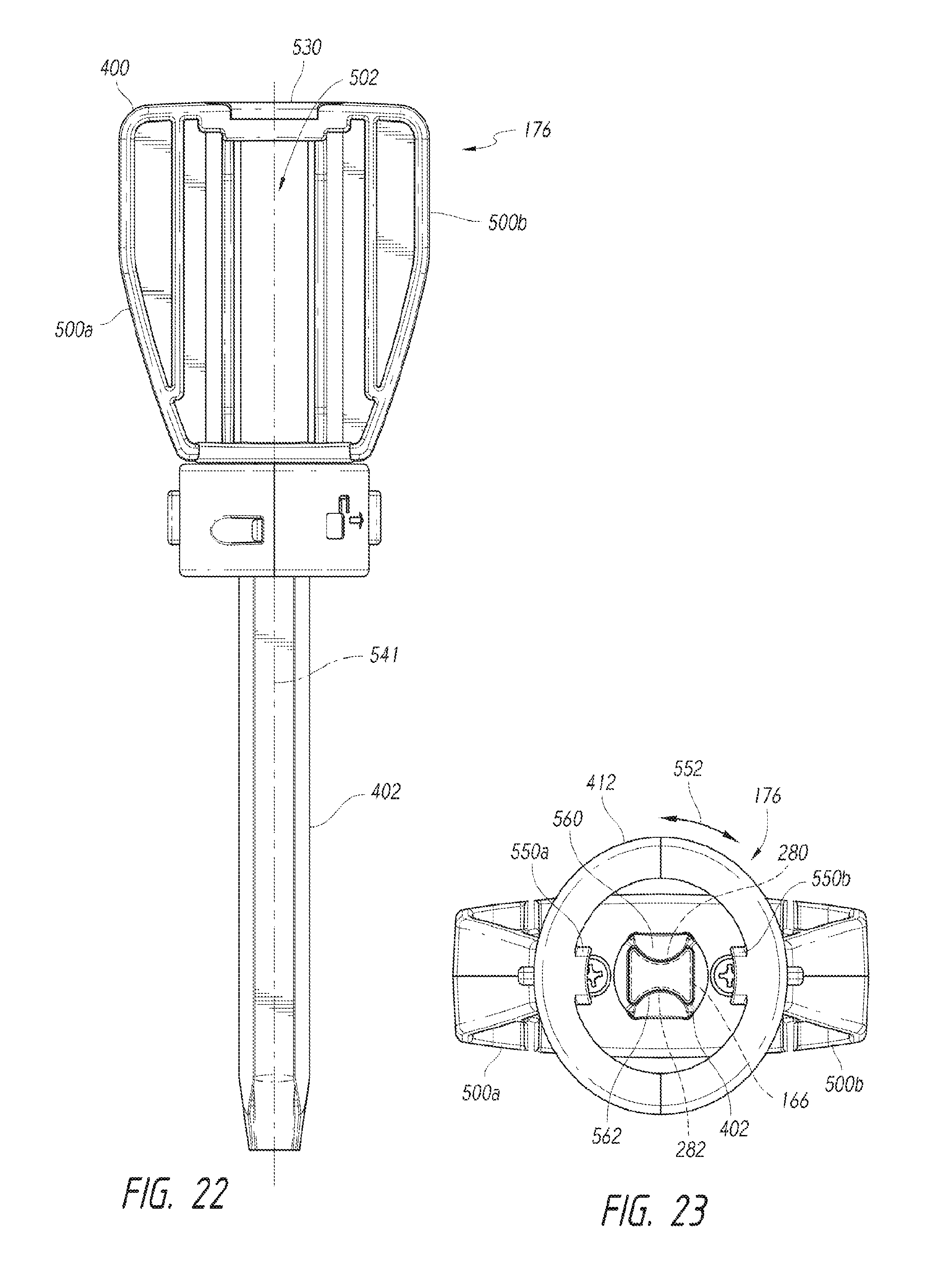
D00014
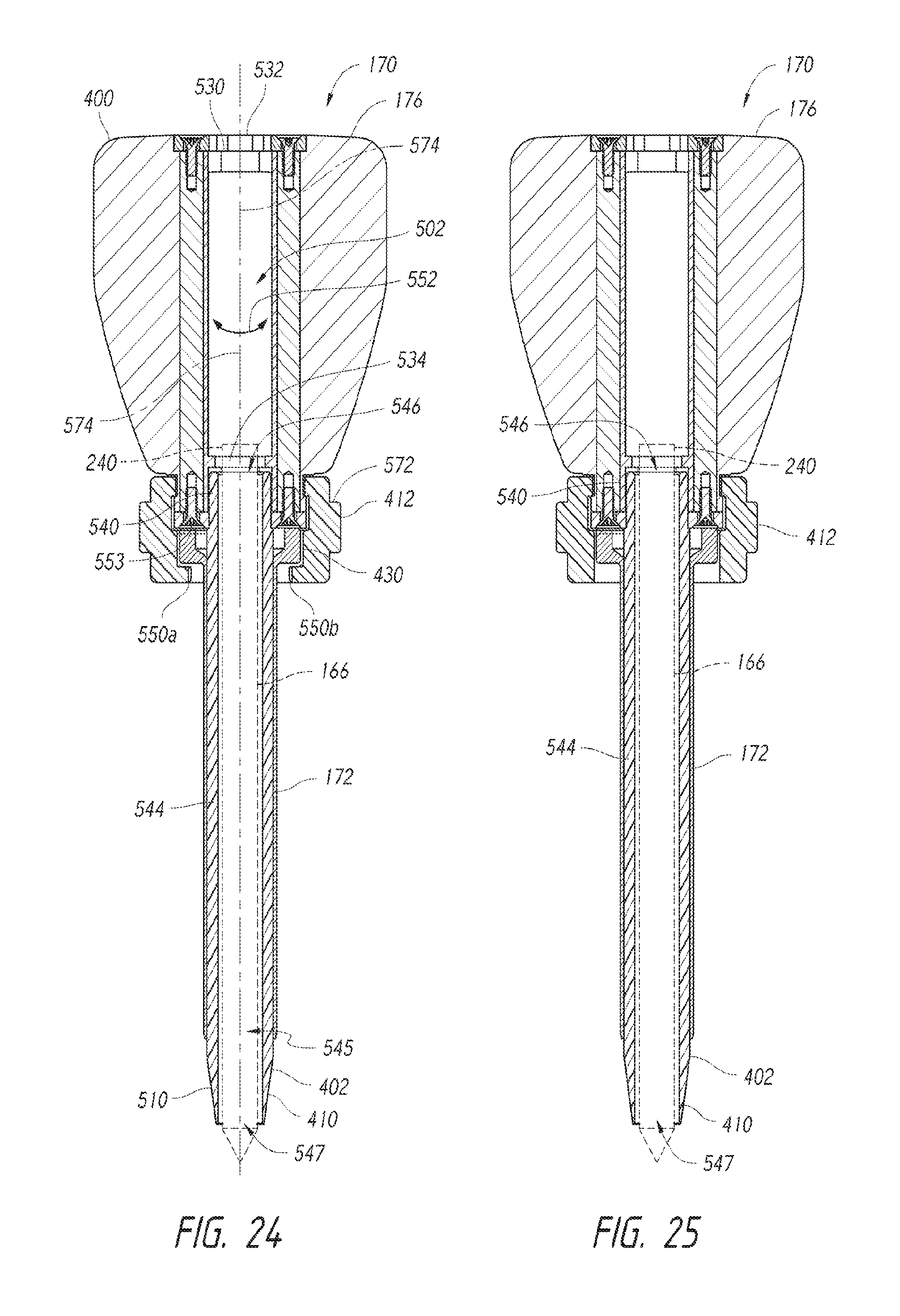
D00015

D00016

D00017

D00018
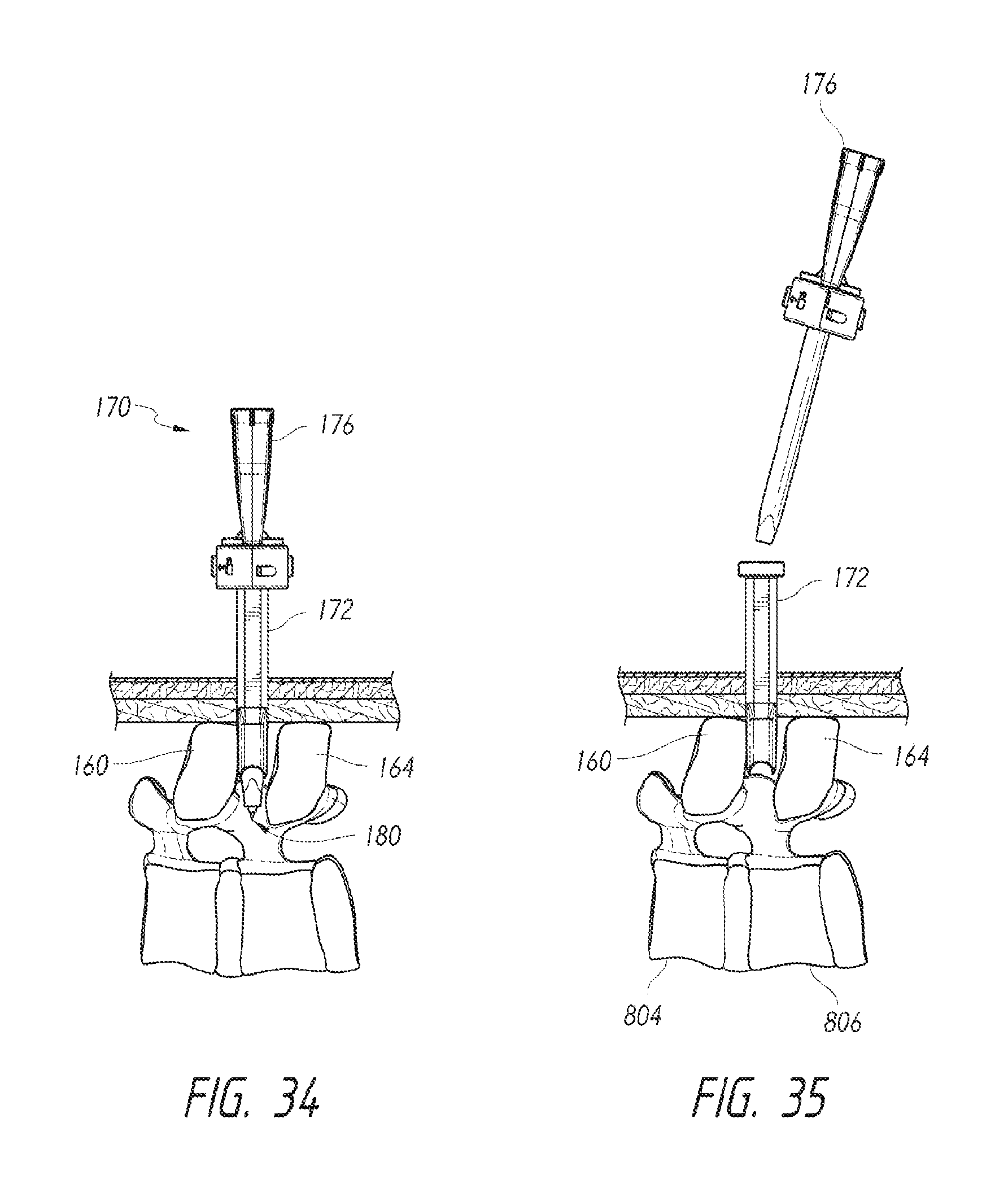
D00019

D00020

D00021
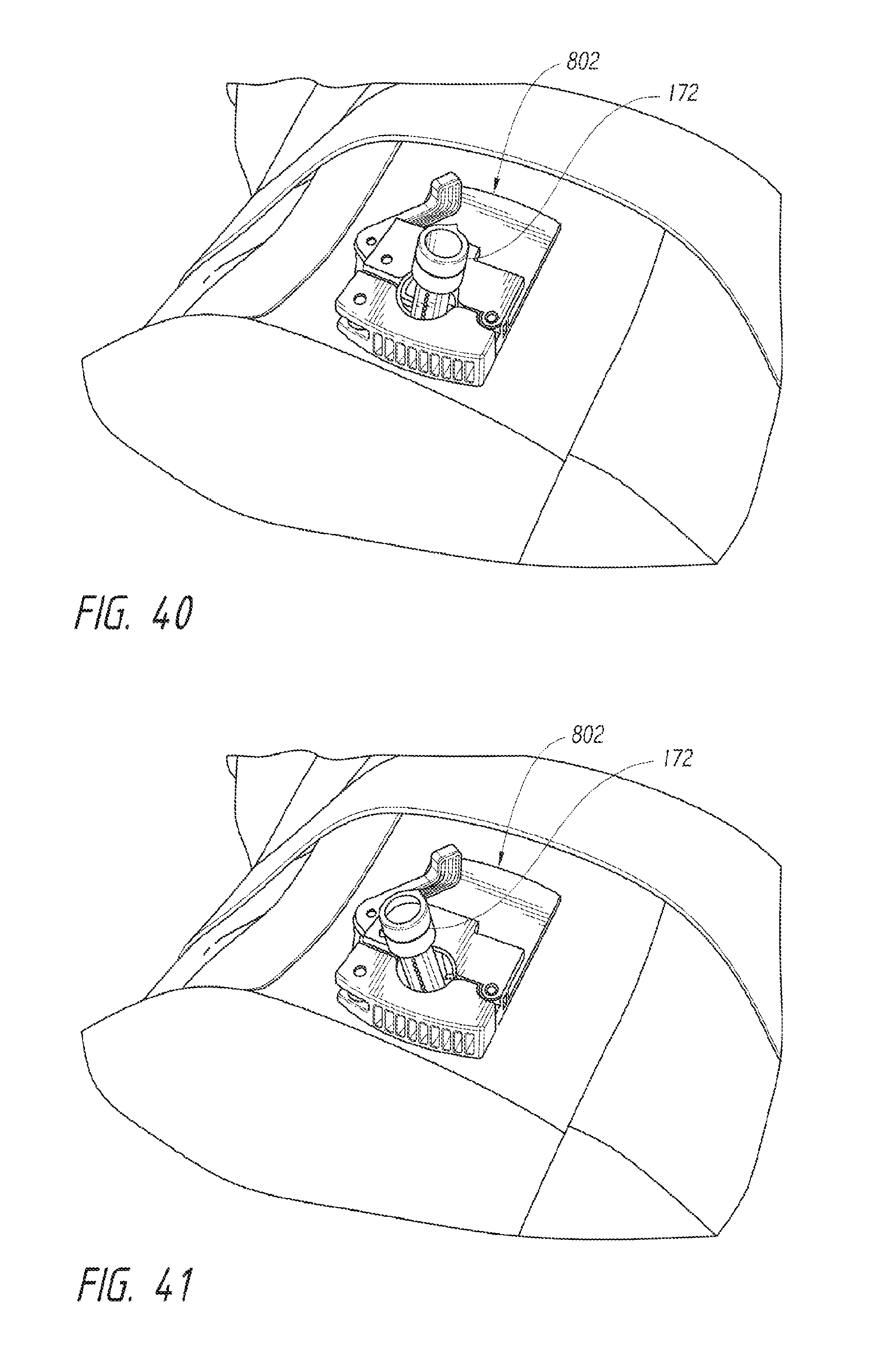
D00022

D00023

D00024

D00025
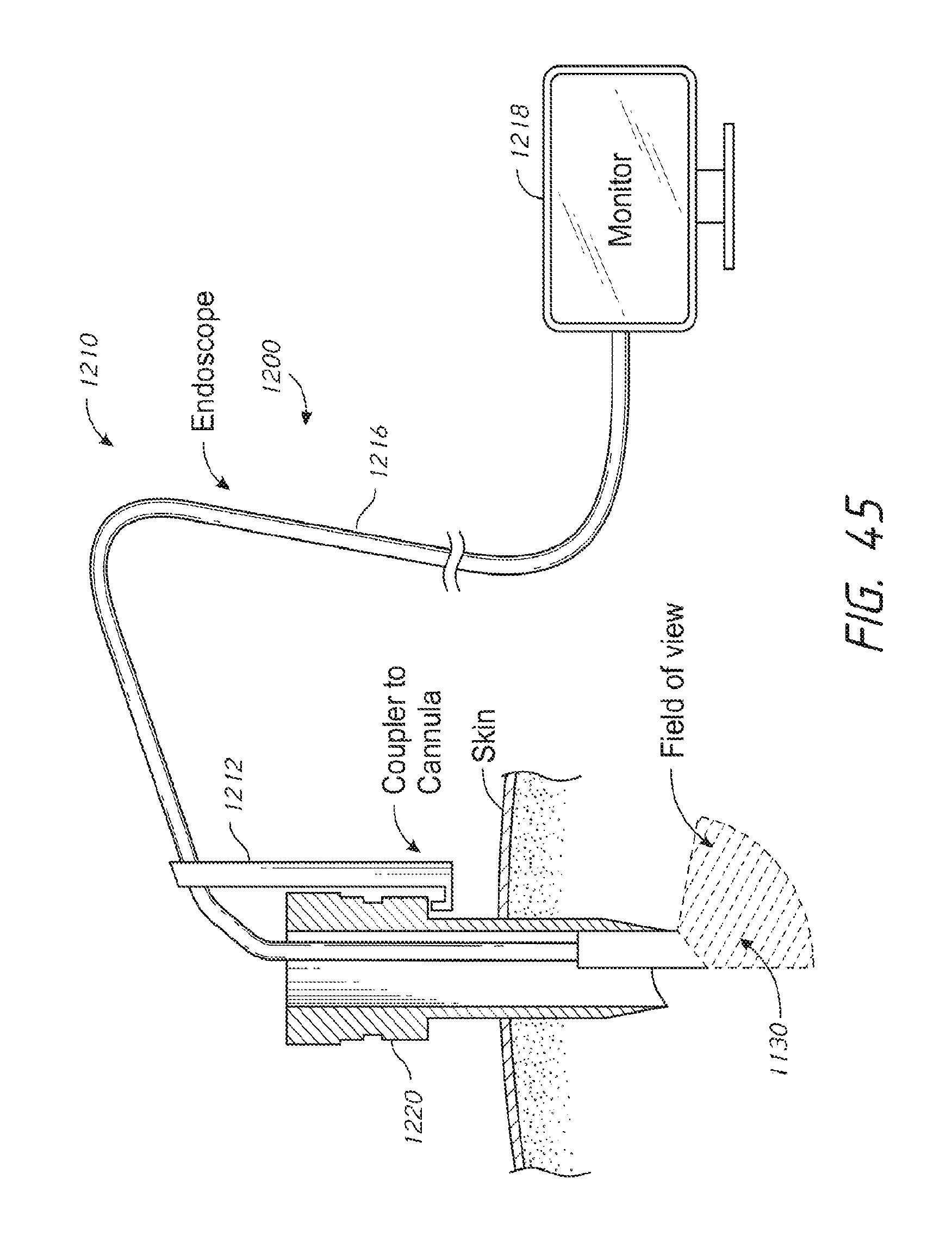
D00026
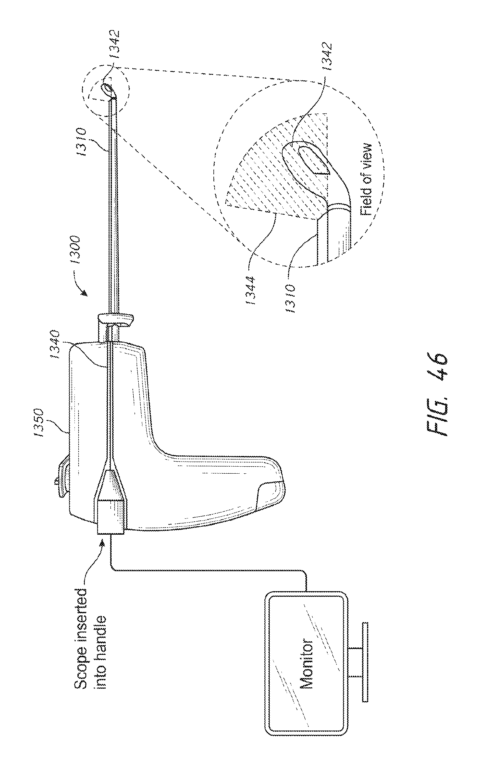
D00027

XML
uspto.report is an independent third-party trademark research tool that is not affiliated, endorsed, or sponsored by the United States Patent and Trademark Office (USPTO) or any other governmental organization. The information provided by uspto.report is based on publicly available data at the time of writing and is intended for informational purposes only.
While we strive to provide accurate and up-to-date information, we do not guarantee the accuracy, completeness, reliability, or suitability of the information displayed on this site. The use of this site is at your own risk. Any reliance you place on such information is therefore strictly at your own risk.
All official trademark data, including owner information, should be verified by visiting the official USPTO website at www.uspto.gov. This site is not intended to replace professional legal advice and should not be used as a substitute for consulting with a legal professional who is knowledgeable about trademark law.