Surgical fastener applying apparatus
Gupta , et al. Dec
U.S. patent number 10,517,593 [Application Number 15/033,720] was granted by the patent office on 2019-12-31 for surgical fastener applying apparatus. This patent grant is currently assigned to Covidien LP. The grantee listed for this patent is Covidien LP. Invention is credited to Harshottam Singh Dhakad, Kiran Garikipati, Arvind Kumar Gupta, Nikhil R. Katre, Mangesh Patankar, Vinayan Vivekanandan.


View All Diagrams
| United States Patent | 10,517,593 |
| Gupta , et al. | December 31, 2019 |
Surgical fastener applying apparatus
Abstract
The present disclosure relates to a surgical fastener applying apparatus comprising: an anvil half-section including a distal anvil portion and a proximal handle portion; a cartridge receiving half section defining an elongated channel member and including at least one hinge member (173, 1194) supported on a bottom wall of the elongated channel member, the elongated channel member having a distal portion dimensioned to releasably receive a single use loading unit and a proximal portion configured to support a firing assembly, and wherein the at least one hinge member defines an opening; and a clamping lever (16) pivotally secured to the cartridge receiving half-section, the clamping lever having a proximal end, a distal end and a pivot member (187, 1187) supported in cantilevered fashion on the distal end of the clamping lever; the pivot member of the clamping lever being slidably received within the opening of the at least one hinge member to pivotally secure the clamping lever to the cartridge receiving half-section, the clamping lever being movable from an undamped position to a clamped position to releasably secure the anvil portion of the anvil half-section in close approximation with the single use loading unit supported within the elongated channel member.
| Inventors: | Gupta; Arvind Kumar (Uttar Pradesh, IN), Dhakad; Harshottam Singh (Madhya Pradesh, IN), Garikipati; Kiran (Andhra Pradesh, IN), Katre; Nikhil R. (Maharashtra, IN), Vivekanandan; Vinayan (Kerala, IN), Patankar; Mangesh (Navi Mumbai Maharashtra, IN) | ||||||||||
|---|---|---|---|---|---|---|---|---|---|---|---|
| Applicant: |
|
||||||||||
| Assignee: | Covidien LP (Mansfield,
MA) |
||||||||||
| Family ID: | 49640167 | ||||||||||
| Appl. No.: | 15/033,720 | ||||||||||
| Filed: | November 4, 2013 | ||||||||||
| PCT Filed: | November 04, 2013 | ||||||||||
| PCT No.: | PCT/US2013/068263 | ||||||||||
| 371(c)(1),(2),(4) Date: | May 02, 2016 | ||||||||||
| PCT Pub. No.: | WO2015/065487 | ||||||||||
| PCT Pub. Date: | May 07, 2015 |
Prior Publication Data
| Document Identifier | Publication Date | |
|---|---|---|
| US 20160249920 A1 | Sep 1, 2016 | |
| Current U.S. Class: | 1/1 |
| Current CPC Class: | A61B 17/072 (20130101); A61B 17/07207 (20130101); A61B 2017/0023 (20130101); A61B 2017/0042 (20130101); A61B 2017/07257 (20130101); A61B 2017/07285 (20130101); A61B 2017/07271 (20130101) |
| Current International Class: | A61B 17/072 (20060101); A61B 17/00 (20060101) |
References Cited [Referenced By]
U.S. Patent Documents
| 3079606 | March 1963 | Bobrov et al. |
| 3490675 | January 1970 | Green et al. |
| 3499591 | March 1970 | Green |
| 3777538 | December 1973 | Weatherly et al. |
| 3882854 | May 1975 | Hulka et al. |
| 4027510 | June 1977 | Hiltebrandt |
| 4086926 | May 1978 | Green et al. |
| 4241861 | December 1980 | Fleischer |
| 4244372 | January 1981 | Kapitanov et al. |
| 4429695 | February 1984 | Green |
| 4505414 | March 1985 | Filipi |
| 4520817 | June 1985 | Green |
| 4589413 | May 1986 | Malyshev et al. |
| 4596351 | June 1986 | Fedotov et al. |
| 4602634 | July 1986 | Barkley |
| 4605001 | August 1986 | Rothfuss et al. |
| 4608981 | September 1986 | Rothfuss et al. |
| 4610383 | September 1986 | Rothfuss et al. |
| 4633861 | January 1987 | Chow et al. |
| 4633874 | January 1987 | Chow et al. |
| 4671445 | June 1987 | Barker et al. |
| 4700703 | October 1987 | Resnick et al. |
| 4703887 | November 1987 | Clanton et al. |
| 4728020 | March 1988 | Green et al. |
| 4752024 | June 1988 | Green et al. |
| 4784137 | November 1988 | Kulik et al. |
| 4863088 | September 1989 | Redmond et al. |
| 4869415 | September 1989 | Fox |
| 4892244 | January 1990 | Fox et al. |
| 4955959 | September 1990 | Tompkins et al. |
| 4978049 | December 1990 | Green |
| 4991764 | February 1991 | Mericle |
| 5014899 | May 1991 | Presty et al. |
| 5031814 | July 1991 | Tompkins et al. |
| 5040715 | August 1991 | Green et al. |
| 5065929 | November 1991 | Schulze et al. |
| 5071430 | December 1991 | de Salis et al. |
| 5074454 | December 1991 | Peters |
| 5083695 | January 1992 | Foslien et al. |
| 5084057 | January 1992 | Green et al. |
| 5106008 | April 1992 | Tompkins et al. |
| 5111987 | May 1992 | Moeinzadeh et al. |
| 5129570 | July 1992 | Schulze et al. |
| 5141144 | August 1992 | Foslien et al. |
| 5156315 | October 1992 | Green et al. |
| 5156614 | October 1992 | Green et al. |
| 5163943 | November 1992 | Mohiuddin et al. |
| 5170925 | December 1992 | Madden et al. |
| 5171247 | December 1992 | Hughett et al. |
| 5173133 | December 1992 | Morin et al. |
| 5180092 | January 1993 | Crainich |
| 5188274 | February 1993 | Moeinzadeh et al. |
| 5220928 | June 1993 | Oddsen et al. |
| 5221036 | June 1993 | Takase |
| 5242457 | September 1993 | Akopov et al. |
| 5246156 | September 1993 | Rothfuss et al. |
| 5253793 | October 1993 | Green et al. |
| 5263629 | November 1993 | Trumbull et al. |
| RE34519 | January 1994 | Fox et al. |
| 5275323 | January 1994 | Schulze et al. |
| 5282807 | February 1994 | Knoepfler |
| 5289963 | March 1994 | McGarry et al. |
| 5307976 | May 1994 | Olson et al. |
| 5308576 | May 1994 | Green et al. |
| 5312023 | May 1994 | Green et al. |
| 5318221 | June 1994 | Green et al. |
| 5326013 | July 1994 | Green et al. |
| 5328077 | July 1994 | Lou |
| 5330486 | July 1994 | Wilk |
| 5332142 | July 1994 | Robinson et al. |
| 5336232 | August 1994 | Green et al. |
| 5344061 | September 1994 | Crainich |
| 5352238 | October 1994 | Green et al. |
| 5356064 | October 1994 | Green et al. |
| 5358506 | October 1994 | Green et al. |
| 5364001 | November 1994 | Bryan |
| 5364002 | November 1994 | Green et al. |
| 5364003 | November 1994 | Williamson, IV |
| 5366133 | November 1994 | Geiste |
| 5376095 | December 1994 | Ortiz |
| 5379933 | January 1995 | Green et al. |
| 5381943 | January 1995 | Allen et al. |
| 5382255 | January 1995 | Castro et al. |
| 5383880 | January 1995 | Hooven |
| 5389098 | February 1995 | Tsuruta et al. |
| 5395033 | March 1995 | Byrne et al. |
| 5395034 | March 1995 | Allen et al. |
| 5397046 | March 1995 | Savage et al. |
| 5397324 | March 1995 | Carroll et al. |
| 5403312 | April 1995 | Yates et al. |
| 5405072 | April 1995 | Zlock |
| 5407293 | April 1995 | Crainich |
| 5413268 | May 1995 | Green et al. |
| 5415334 | May 1995 | Williamson et al. |
| 5415335 | May 1995 | Knodell, Jr. |
| 5417361 | May 1995 | Williamson, IV |
| 5423471 | June 1995 | Mastri et al. |
| 5425745 | June 1995 | Green et al. |
| 5431322 | July 1995 | Green et al. |
| 5431323 | July 1995 | Smith et al. |
| 5433721 | July 1995 | Hooven et al. |
| 5441193 | August 1995 | Gravener |
| 5445304 | August 1995 | Plyley et al. |
| 5447265 | September 1995 | Vidal et al. |
| 5452837 | September 1995 | Williamson, IV et al. |
| 5456401 | October 1995 | Green et al. |
| 5464300 | November 1995 | Crainich |
| 5465895 | November 1995 | Knodel et al. |
| 5465896 | November 1995 | Allen |
| 5467911 | November 1995 | Tsuruta et al. |
| 5470007 | November 1995 | Plyley et al. |
| 5470010 | November 1995 | Rothfuss et al. |
| 5472132 | December 1995 | Savage et al. |
| 5474566 | December 1995 | Alesi et al. |
| 5476206 | December 1995 | Green et al. |
| 5478003 | December 1995 | Green et al. |
| 5480089 | January 1996 | Blewett |
| 5482197 | January 1996 | Green et al. |
| 5484095 | January 1996 | Green et al. |
| 5484451 | January 1996 | Akopov et al. |
| 5485947 | January 1996 | Olson et al. |
| 5485952 | January 1996 | Fontayne |
| 5486185 | January 1996 | Freitas et al. |
| 5487499 | January 1996 | Sorrentino et al. |
| 5487500 | January 1996 | Knodel et al. |
| 5489058 | February 1996 | Plyley et al. |
| 5490856 | February 1996 | Person et al. |
| 5497933 | March 1996 | DeFonzo et al. |
| 5501689 | March 1996 | Green et al. |
| 5505363 | April 1996 | Green et al. |
| 5507426 | April 1996 | Young et al. |
| 5518163 | May 1996 | Hooven |
| 5518164 | May 1996 | Hooven |
| 5529235 | June 1996 | Boiarski et al. |
| 5531744 | July 1996 | Nardella et al. |
| 5535934 | July 1996 | Boiarski et al. |
| 5535935 | July 1996 | Vidal et al. |
| 5535937 | July 1996 | Boiarski et al. |
| 5540375 | July 1996 | Bolanos et al. |
| 5542594 | August 1996 | McKean et al. |
| 5549628 | August 1996 | Cooper et al. |
| 5551622 | September 1996 | Yoon |
| 5553765 | September 1996 | Knodel et al. |
| 5554164 | September 1996 | Wilson et al. |
| 5554169 | September 1996 | Green et al. |
| 5560530 | October 1996 | Bolanos et al. |
| 5560532 | October 1996 | DeFonzo et al. |
| 5562239 | October 1996 | Boiarski et al. |
| 5562241 | October 1996 | Knodel et al. |
| 5562682 | October 1996 | Oberlin et al. |
| 5562701 | October 1996 | Huiterna et al. |
| 5564615 | October 1996 | Bishop et al. |
| 5571116 | November 1996 | Bolanos et al. |
| 5573169 | November 1996 | Green et al. |
| 5573543 | November 1996 | Akopov et al. |
| 5575799 | November 1996 | Bolanos et al. |
| 5575803 | November 1996 | Cooper et al. |
| 5577654 | November 1996 | Bishop |
| 5584425 | December 1996 | Savage et al. |
| 5586711 | December 1996 | Plyley et al. |
| 5588580 | December 1996 | Paul et al. |
| 5588581 | December 1996 | Conlon et al. |
| 5597107 | January 1997 | Knodel et al. |
| 5601224 | February 1997 | Bishop et al. |
| 5607095 | March 1997 | Smith et al. |
| 5615820 | April 1997 | Viola |
| 5618291 | April 1997 | Thompson et al. |
| 5624452 | April 1997 | Yates |
| 5626587 | May 1997 | Bishop et al. |
| 5628446 | May 1997 | Geiste et al. |
| 5630539 | May 1997 | Plyley et al. |
| 5630540 | May 1997 | Blewett |
| 5630541 | May 1997 | Williamson, IV et al. |
| 5632432 | May 1997 | Schulze et al. |
| 5634584 | June 1997 | Okorocha et al. |
| 5636779 | June 1997 | Palmer |
| 5636780 | June 1997 | Green et al. |
| 5645209 | July 1997 | Green et al. |
| 5647526 | July 1997 | Green et al. |
| 5651491 | July 1997 | Heaton et al. |
| 5653373 | August 1997 | Green et al. |
| 5653374 | August 1997 | Young et al. |
| 5653721 | August 1997 | Knodel et al. |
| 5655698 | August 1997 | Yoon |
| 5657921 | August 1997 | Young et al. |
| 5658300 | August 1997 | Bito et al. |
| 5662258 | September 1997 | Knodel et al. |
| 5662259 | September 1997 | Yoon |
| 5662260 | September 1997 | Yoon |
| 5662662 | September 1997 | Bishop et al. |
| 5662666 | September 1997 | Onuki et al. |
| 5665085 | September 1997 | Nardella |
| 5667517 | September 1997 | Hooven |
| 5669544 | September 1997 | Schulze et al. |
| 5673840 | October 1997 | Schulze et al. |
| 5673841 | October 1997 | Schulze et al. |
| 5673842 | October 1997 | Bittner et al. |
| 5676674 | October 1997 | Bolanos et al. |
| 5680981 | October 1997 | Mililli et al. |
| 5680982 | October 1997 | Schulze et al. |
| 5680983 | October 1997 | Plyley et al. |
| 5690269 | November 1997 | Bolanos et al. |
| 5692668 | December 1997 | Schulze et al. |
| 5697542 | December 1997 | Knodel et al. |
| 5702409 | December 1997 | Raybum et al. |
| 5704534 | January 1998 | Huitema et al. |
| 5706997 | January 1998 | Green et al. |
| 5709334 | January 1998 | Sorrentino et al. |
| 5711472 | January 1998 | Bryan |
| 5713505 | February 1998 | Huitema |
| 5715988 | February 1998 | Palmer |
| 5716366 | February 1998 | Yates |
| 5718359 | February 1998 | Palmer et al. |
| 5725536 | March 1998 | Oberlin et al. |
| 5725554 | March 1998 | Simon et al. |
| 5728110 | March 1998 | Vidal et al. |
| 5732806 | March 1998 | Foshee et al. |
| 5735848 | April 1998 | Yates et al. |
| 5743456 | April 1998 | Jones et al. |
| 5749893 | May 1998 | Vidal et al. |
| 5752644 | May 1998 | Bolanos et al. |
| 5762255 | June 1998 | Chrisman et al. |
| 5762256 | June 1998 | Mastri et al. |
| 5769303 | June 1998 | Knodel et al. |
| 5769892 | June 1998 | Kingwell |
| 5772099 | June 1998 | Gravener |
| 5772673 | June 1998 | Cuny et al. |
| 5779130 | July 1998 | Alesi et al. |
| 5779131 | July 1998 | Knodel et al. |
| 5779132 | July 1998 | Knodel et al. |
| 5782396 | July 1998 | Mastri et al. |
| 5782397 | July 1998 | Koukline |
| 5782834 | July 1998 | Lucey et al. |
| 5785232 | July 1998 | Vidal |
| 5797536 | August 1998 | Smith et al. |
| 5797537 | August 1998 | Oberlin et al. |
| 5797538 | August 1998 | Heaton et al. |
| 5810811 | September 1998 | Yates et al. |
| 5810855 | September 1998 | Raybum et al. |
| 5814055 | September 1998 | Knodel et al. |
| 5814057 | September 1998 | Oi et al. |
| 5816471 | October 1998 | Plyley et al. |
| 5817109 | October 1998 | McGarry et al. |
| 5820009 | October 1998 | Melling et al. |
| 5823066 | October 1998 | Huitema et al. |
| 5826776 | October 1998 | Schulze et al. |
| 5829662 | November 1998 | Allen et al. |
| 5833695 | November 1998 | Yoon |
| 5836147 | November 1998 | Schnipke |
| 5862972 | January 1999 | Green et al. |
| 5865361 | February 1999 | Milliman et al. |
| 5871135 | February 1999 | Williamson, IV et al. |
| 5873873 | February 1999 | Smith et al. |
| 5878938 | March 1999 | Bittner et al. |
| 5893506 | April 1999 | Powell |
| 5894979 | April 1999 | Powell |
| 5897562 | April 1999 | Bolanos et al. |
| 5901895 | May 1999 | Heaton et al. |
| 5911352 | June 1999 | Racenet et al. |
| 5911353 | June 1999 | Bolanos et al. |
| 5918791 | July 1999 | Sorrentino et al. |
| 5919198 | July 1999 | Graves, Jr. et al. |
| 5922001 | July 1999 | Yoon |
| 5931847 | August 1999 | Bittner et al. |
| 5941442 | August 1999 | Geiste et al. |
| 5954259 | September 1999 | Viola et al. |
| 5964774 | October 1999 | McKean et al. |
| 5980510 | November 1999 | Tsonton et al. |
| 5988479 | November 1999 | Palmer |
| 6004335 | December 1999 | Vaitekunas et al. |
| 6010054 | January 2000 | Johnson et al. |
| 6032849 | March 2000 | Mastri et al. |
| 6045560 | April 2000 | McKean et al. |
| 6063097 | May 2000 | Oi et al. |
| 6079606 | June 2000 | Milliman et al. |
| 6099551 | August 2000 | Gabbay |
| 6109500 | August 2000 | Alli et al. |
| 6131789 | October 2000 | Schulze et al. |
| 6131790 | October 2000 | Piraka |
| 6155473 | December 2000 | Tompkins et al. |
| 6197017 | March 2001 | Brock et al. |
| 6202914 | March 2001 | Geiste et al. |
| 6241139 | June 2001 | Milliman et al. |
| 6250532 | June 2001 | Green et al. |
| 6264086 | July 2001 | McGuckin, Jr. |
| 6264087 | July 2001 | Whitman |
| 6279809 | August 2001 | Nicolo |
| 6315183 | November 2001 | Piraka |
| 6315184 | November 2001 | Whitman |
| 6325810 | December 2001 | Hamilton et al. |
| 6330965 | December 2001 | Milliman et al. |
| 6391038 | May 2002 | Vargas et al. |
| 6398797 | June 2002 | Bombard et al. |
| 6436097 | August 2002 | Nardella |
| 6439446 | August 2002 | Perry et al. |
| 6443973 | September 2002 | Whitman |
| 6478804 | November 2002 | Vargas et al. |
| 6488196 | December 2002 | Fenton, Jr. |
| 6503257 | January 2003 | Grant et al. |
| 6505768 | January 2003 | Whitman |
| 6544274 | April 2003 | Danitz et al. |
| 6554844 | April 2003 | Lee et al. |
| 6565554 | May 2003 | Niemeyer |
| 6587750 | July 2003 | Gerbi et al. |
| 6592597 | July 2003 | Grant et al. |
| 6594552 | July 2003 | Nowlin et al. |
| 6602252 | August 2003 | Mollenauer |
| 6619529 | September 2003 | Green et al. |
| D480808 | October 2003 | Wells et al. |
| 6644532 | November 2003 | Green et al. |
| 6656193 | December 2003 | Grant et al. |
| 6669073 | December 2003 | Milliman et al. |
| 6681978 | January 2004 | Geiste et al. |
| 6698643 | March 2004 | Whitman |
| 6716232 | April 2004 | Vidal et al. |
| 6722552 | April 2004 | Fenton, Jr. |
| 6755338 | June 2004 | Hahnen et al. |
| 6783524 | August 2004 | Anderson et al. |
| 6786382 | September 2004 | Hoffman |
| 6817509 | November 2004 | Geiste et al. |
| 6830174 | December 2004 | Hillstead et al. |
| 6835199 | December 2004 | McGuckin, Jr. et al. |
| 6843403 | January 2005 | Whitman |
| RE38708 | March 2005 | Bolanos et al. |
| 6877647 | April 2005 | Green et al. |
| 6889116 | May 2005 | Jinno |
| 6905057 | June 2005 | Swayze et al. |
| 6945444 | September 2005 | Gresham et al. |
| 6953138 | October 2005 | Dworak et al. |
| 6953139 | October 2005 | Milliman et al. |
| 6959852 | November 2005 | Shelton, IV et al. |
| 6962594 | November 2005 | Thevenet |
| 6964363 | November 2005 | Wales et al. |
| 6978921 | December 2005 | Shelton, IV et al. |
| 6981628 | January 2006 | Wales |
| 6986451 | January 2006 | Mastri et al. |
| 6988649 | January 2006 | Shelton, IV et al. |
| 6991627 | January 2006 | Madhani et al. |
| 6994714 | February 2006 | Vargas et al. |
| 7000818 | February 2006 | Shelton, IV et al. |
| 7000819 | February 2006 | Swayze et al. |
| 7032799 | April 2006 | Viola et al. |
| 7044352 | May 2006 | Shelton, IV et al. |
| 7044353 | May 2006 | Mastri et al. |
| 7055730 | June 2006 | Ehrenfels et al. |
| 7055731 | June 2006 | Shelton, IV et al. |
| 7059508 | June 2006 | Shelton, IV et al. |
| 7070083 | July 2006 | Jankowski |
| 7083075 | August 2006 | Swayze et al. |
| 7097089 | August 2006 | Marczyk |
| 7111769 | September 2006 | Wales et al. |
| 7114642 | October 2006 | Whitman |
| 7121446 | October 2006 | Arad et al. |
| 7128253 | October 2006 | Mastri et al. |
| 7128254 | October 2006 | Shelton, IV et al. |
| 7140527 | November 2006 | Ehrenfels et al. |
| 7140528 | November 2006 | Shelton, IV |
| 7143923 | December 2006 | Shelton, IV et al. |
| 7143924 | December 2006 | Scirica et al. |
| 7143925 | December 2006 | Shelton, IV et al. |
| 7143926 | December 2006 | Shelton, IV et al. |
| 7147138 | December 2006 | Shelton, IV |
| 7159750 | January 2007 | Racenet et al. |
| 7168604 | January 2007 | Milliman et al. |
| 7172104 | February 2007 | Scirica et al. |
| 7188758 | March 2007 | Viola et al. |
| 7207471 | April 2007 | Heinrich et al. |
| 7213736 | May 2007 | Wales et al. |
| 7225963 | June 2007 | Scirica |
| 7225964 | June 2007 | Mastri et al. |
| 7238195 | July 2007 | Viola |
| 7246734 | July 2007 | Shelton, IV |
| 7258262 | August 2007 | Mastri et al. |
| 7278562 | October 2007 | Mastri et al. |
| 7278563 | October 2007 | Green |
| 7287682 | October 2007 | Ezzat et al. |
| 7293685 | November 2007 | Ehrenfels et al. |
| 7296722 | November 2007 | Ivanko |
| 7296724 | November 2007 | Green et al. |
| 7296772 | November 2007 | Wang |
| 7300444 | November 2007 | Nielsen et al. |
| 7303107 | December 2007 | Milliman et al. |
| 7303108 | December 2007 | Shelton, IV |
| 7308998 | December 2007 | Mastri et al. |
| 7326232 | February 2008 | Viola et al. |
| 7328828 | February 2008 | Ortiz et al. |
| 7328829 | February 2008 | Arad et al. |
| 7334717 | February 2008 | Rethy et al. |
| 7354447 | April 2008 | Shelton, IV et al. |
| 7357287 | April 2008 | Shelton, IV et al. |
| 7364061 | April 2008 | Swayze et al. |
| 7367485 | May 2008 | Shelton, IV et al. |
| 7377928 | May 2008 | Zubik et al. |
| 7380695 | June 2008 | Doll et al. |
| 7380696 | June 2008 | Shelton, IV et al. |
| 7396356 | July 2008 | Mollenauer |
| 7398907 | July 2008 | Racenet et al. |
| 7399310 | July 2008 | Edoga et al. |
| 7401720 | July 2008 | Durrani |
| 7401721 | July 2008 | Holsten et al. |
| 7404508 | July 2008 | Smith et al. |
| 7404509 | July 2008 | Ortiz et al. |
| 7407074 | August 2008 | Ortiz et al. |
| 7407075 | August 2008 | Holsten et al. |
| 7407077 | August 2008 | Ortiz et al. |
| 7407078 | August 2008 | Shelton, IV et al. |
| 7416101 | August 2008 | Shelton, IV et al. |
| 7419080 | September 2008 | Smith et al. |
| 7419081 | September 2008 | Ehrenfels et al. |
| 7419495 | September 2008 | Menn et al. |
| 7422139 | September 2008 | Shelton, IV et al. |
| 7424965 | September 2008 | Racenet et al. |
| 7431189 | October 2008 | Shelton, IV et al. |
| 7431730 | October 2008 | Viola |
| 7434715 | October 2008 | Shelton, IV et al. |
| 7434717 | October 2008 | Shelton, IV et al. |
| 7438208 | October 2008 | Larson |
| 7438209 | October 2008 | Hess et al. |
| 7441684 | October 2008 | Shelton, IV et al. |
| 7441685 | October 2008 | Boudreaux |
| 7448525 | November 2008 | Shelton, IV et al. |
| 7451904 | November 2008 | Shelton, IV |
| 7455208 | November 2008 | Wales et al. |
| 7455676 | November 2008 | Holsten et al. |
| 7458494 | December 2008 | Matsutani et al. |
| 7461767 | December 2008 | Viola et al. |
| 7462185 | December 2008 | Knodel |
| 7464846 | December 2008 | Shelton, IV et al. |
| 7464847 | December 2008 | Viola et al. |
| 7464848 | December 2008 | Green et al. |
| 7464849 | December 2008 | Shelton, IV et al. |
| 7467740 | December 2008 | Shelton, IV et al. |
| 7472814 | January 2009 | Mastri et al. |
| 7472815 | January 2009 | Shelton, IV et al. |
| 7472816 | January 2009 | Holsten et al. |
| 7473258 | January 2009 | Clauson et al. |
| 7481347 | January 2009 | Roy |
| 7481348 | January 2009 | Marczyk |
| 7481349 | January 2009 | Holsten et al. |
| 7481824 | January 2009 | Boudreaux et al. |
| 7487899 | February 2009 | Shelton, IV et al. |
| 7490749 | February 2009 | Schall et al. |
| 7494039 | February 2009 | Racenet et al. |
| 7500979 | March 2009 | Hueil et al. |
| 7503474 | March 2009 | Hillstead et al. |
| 7506790 | March 2009 | Shelton, IV |
| 7506791 | March 2009 | Omaits et al. |
| 7510107 | March 2009 | Timm et al. |
| 7513408 | April 2009 | Shelton, IV et al. |
| 7517356 | April 2009 | Heinrich |
| 7537602 | May 2009 | Whitman |
| 7543729 | June 2009 | Ivanko |
| 7543730 | June 2009 | Marczyk |
| 7543731 | June 2009 | Green et al. |
| 7552854 | June 2009 | Wixey et al. |
| 7556185 | July 2009 | Viola |
| 7556186 | July 2009 | Milliman |
| 7559450 | July 2009 | Wales et al. |
| 7559452 | July 2009 | Wales et al. |
| 7559453 | July 2009 | Heinrich et al. |
| 7559937 | July 2009 | de la Torre et al. |
| 7565993 | July 2009 | Milliman et al. |
| 7568603 | August 2009 | Shelton, IV et al. |
| 7568604 | August 2009 | Ehrenfels et al. |
| 7571845 | August 2009 | Viola |
| 7575144 | August 2009 | Ortiz et al. |
| 7584880 | September 2009 | Racenet et al. |
| 7588174 | September 2009 | Holsten et al. |
| 7588175 | September 2009 | Timm et al. |
| 7588176 | September 2009 | Timm et al. |
| 7588177 | September 2009 | Racenet |
| 7597229 | October 2009 | Boudreaux et al. |
| 7597230 | October 2009 | Racenet et al. |
| 7600663 | October 2009 | Green |
| 7604150 | October 2009 | Boudreaux |
| 7604151 | October 2009 | Hess et al. |
| 7607557 | October 2009 | Shelton, IV et al. |
| 7611038 | November 2009 | Racenet et al. |
| 7617961 | November 2009 | Viola |
| 7624902 | December 2009 | Marczyk et al. |
| 7624903 | December 2009 | Green et al. |
| 7631793 | December 2009 | Rethy et al. |
| 7631794 | December 2009 | Rethy et al. |
| 7635073 | December 2009 | Heinrich |
| 7635074 | December 2009 | Olson et al. |
| 7635373 | December 2009 | Ortiz |
| 7637409 | December 2009 | Marczyk |
| 7637410 | December 2009 | Marczyk |
| 7641091 | January 2010 | Olson et al. |
| 7641095 | January 2010 | Viola |
| 7644848 | January 2010 | Swayze et al. |
| 7648055 | January 2010 | Marczyk |
| 7651017 | January 2010 | Ortiz et al. |
| 7654431 | February 2010 | Hueil et al. |
| 7658311 | February 2010 | Boudreaux |
| 7658312 | February 2010 | Vidal et al. |
| 7665646 | February 2010 | Prommersberger |
| 7665647 | February 2010 | Shelton, IV et al. |
| 7669746 | March 2010 | Shelton, IV |
| 7670334 | March 2010 | Hueil et al. |
| 7673780 | March 2010 | Shelton, IV et al. |
| 7673781 | March 2010 | Swayze et al. |
| 7673782 | March 2010 | Hess et al. |
| 7673783 | March 2010 | Morgan et al. |
| 7678121 | March 2010 | Knodel |
| 7681772 | March 2010 | Green et al. |
| 7682367 | March 2010 | Shah et al. |
| 7682368 | March 2010 | Bombard et al. |
| 7690547 | April 2010 | Racenet et al. |
| 7694865 | April 2010 | Scirica |
| 7699205 | April 2010 | Ivanko |
| 7703653 | April 2010 | Shah et al. |
| 7721931 | May 2010 | Shelton, IV et al. |
| 7721933 | May 2010 | Ehrenfels et al. |
| 7721935 | May 2010 | Racenet et al. |
| 7726537 | June 2010 | Olson et al. |
| 7726538 | June 2010 | Holsten et al. |
| 7726539 | June 2010 | Holsten et al. |
| 7731072 | June 2010 | Timm et al. |
| 7735703 | June 2010 | Morgan et al. |
| 7740159 | June 2010 | Shelton, IV et al. |
| 7740160 | June 2010 | Viola |
| 7743960 | June 2010 | Whitman et al. |
| 7744628 | June 2010 | Viola |
| 7753245 | July 2010 | Boudreaux et al. |
| 7753248 | July 2010 | Viola |
| 7757924 | July 2010 | Gerbi et al. |
| 7757925 | July 2010 | Viola et al. |
| 7762445 | July 2010 | Heinrich et al. |
| 7766209 | August 2010 | Baxter, III et al. |
| 7766210 | August 2010 | Shelton, IV et al. |
| 7766924 | August 2010 | Bombard et al. |
| 7766928 | August 2010 | Ezzat et al. |
| 7770774 | August 2010 | Mastri et al. |
| 7770775 | August 2010 | Shelton, IV et al. |
| 7776060 | August 2010 | Mooradian et al. |
| 7780055 | August 2010 | Scirica et al. |
| 7784662 | August 2010 | Wales et al. |
| 7789283 | September 2010 | Shah |
| 7789889 | September 2010 | Zubik et al. |
| 7793812 | September 2010 | Moore et al. |
| 7793814 | September 2010 | Racenet et al. |
| 7794475 | September 2010 | Hess et al. |
| 7798385 | September 2010 | Boyden et al. |
| 7798386 | September 2010 | Schall et al. |
| 7799039 | September 2010 | Shelton, IV et al. |
| 7810690 | October 2010 | Bilotti et al. |
| 7810692 | October 2010 | Hall et al. |
| 7810693 | October 2010 | Broehl et al. |
| 7815090 | October 2010 | Marczyk |
| 7815091 | October 2010 | Marczyk |
| 7815092 | October 2010 | Whitman et al. |
| 7819296 | October 2010 | Hueil et al. |
| 7819297 | October 2010 | Doll et al. |
| 7819298 | October 2010 | Hall et al. |
| 7819299 | October 2010 | Shelton, IV et al. |
| 7819796 | October 2010 | Blake et al. |
| 7823760 | November 2010 | Zemlok et al. |
| 7823761 | November 2010 | Boyden et al. |
| 7824426 | November 2010 | Racenet et al. |
| 7828186 | November 2010 | Wales |
| 7828187 | November 2010 | Green et al. |
| 7828188 | November 2010 | Jankowski |
| 7828189 | November 2010 | Holsten et al. |
| 7832408 | November 2010 | Shelton, IV et al. |
| 7832611 | November 2010 | Boyden et al. |
| 7832612 | November 2010 | Baxter, III et al. |
| 7837079 | November 2010 | Holsten et al. |
| 7837081 | November 2010 | Holsten et al. |
| 7841503 | November 2010 | Sonnenschein et al. |
| 7845533 | December 2010 | Marczyk et al. |
| 7845534 | December 2010 | Viola et al. |
| 7845535 | December 2010 | Scircia |
| 7845537 | December 2010 | Shelton, IV et al. |
| 7845538 | December 2010 | Whitman |
| 7850703 | December 2010 | Bombard et al. |
| 7857183 | December 2010 | Shelton, IV |
| 7857184 | December 2010 | Viola |
| 7857185 | December 2010 | Swayze et al. |
| 7857186 | December 2010 | Baxter, III et al. |
| 7861906 | January 2011 | Doll et al. |
| 7861907 | January 2011 | Green et al. |
| 7866524 | January 2011 | Krehel |
| 7866525 | January 2011 | Scirica |
| 7866526 | January 2011 | Green et al. |
| 7866527 | January 2011 | Hall et al. |
| 7866528 | January 2011 | Olson et al. |
| 7870989 | January 2011 | Viola et al. |
| 7886952 | February 2011 | Scirica et al. |
| 7891532 | February 2011 | Mastri et al. |
| 7891533 | February 2011 | Green et al. |
| 7891534 | February 2011 | Wenchell et al. |
| 7896214 | March 2011 | Farascioni |
| 7900805 | March 2011 | Shelton, IV et al. |
| 7901416 | March 2011 | Nolan et al. |
| 7905380 | March 2011 | Shelton, IV et al. |
| 7905381 | March 2011 | Baxter, III et al. |
| 7909039 | March 2011 | Hur |
| 7909220 | March 2011 | Viola |
| 7909221 | March 2011 | Viola et al. |
| 7909224 | March 2011 | Prommersberger |
| 7913891 | March 2011 | Doll et al. |
| 7913893 | March 2011 | Mastri et al. |
| 7914543 | March 2011 | Roth et al. |
| 7918230 | April 2011 | Whitman et al. |
| 7922061 | April 2011 | Shelton, IV et al. |
| 7922063 | April 2011 | Zemlok et al. |
| 7922064 | April 2011 | Boyden et al. |
| 7926691 | April 2011 | Viola et al. |
| 7926692 | April 2011 | Racenet et al. |
| 7934628 | May 2011 | Wenchell et al. |
| 7934630 | May 2011 | Shelton, IV et al. |
| 7934631 | May 2011 | Balbierz et al. |
| 7942300 | May 2011 | Rethy et al. |
| 7942303 | May 2011 | Shah |
| 7950560 | May 2011 | Zemlok et al. |
| 7950561 | May 2011 | Aranyi |
| 7950562 | May 2011 | Beardsley et al. |
| 7954682 | June 2011 | Giordano et al. |
| 7954683 | June 2011 | Knodel et al. |
| 7954684 | June 2011 | Boudreaux |
| 7954685 | June 2011 | Viola |
| 7954686 | June 2011 | Baxter, III et al. |
| 7954687 | June 2011 | Zemlok et al. |
| 7959051 | June 2011 | Smith et al. |
| 7963431 | June 2011 | Scirica |
| 7963432 | June 2011 | Knodel et al. |
| 7963433 | June 2011 | Whitman et al. |
| 7967178 | June 2011 | Scirica et al. |
| 7967179 | June 2011 | Olson et al. |
| 7967180 | June 2011 | Scirica |
| 7975894 | July 2011 | Boyden et al. |
| 7980443 | July 2011 | Scheib et al. |
| 7988026 | August 2011 | Knodel et al. |
| 7988027 | August 2011 | Olson et al. |
| 7988028 | August 2011 | Farascioni et al. |
| 7992758 | August 2011 | Whitman et al. |
| 7997468 | August 2011 | Farascioni |
| 7997469 | August 2011 | Olson et al. |
| 8002795 | August 2011 | Beetel |
| 8006885 | August 2011 | Marczyk |
| 8006887 | August 2011 | Marczyk |
| 8007505 | August 2011 | Weller et al. |
| 8007513 | August 2011 | Nalagatla et al. |
| 8011550 | September 2011 | Aranyi et al. |
| 8011551 | September 2011 | Marczyk et al. |
| 8011552 | September 2011 | Ivanko |
| 8011553 | September 2011 | Mastri et al. |
| 8011555 | September 2011 | Tarinelli et al. |
| 8012170 | September 2011 | Whitman et al. |
| 8015976 | September 2011 | Shah |
| 8016177 | September 2011 | Bettuchi et al. |
| 8016178 | September 2011 | Olson et al. |
| 8020742 | September 2011 | Marczyk |
| 8020743 | September 2011 | Shelton, IV |
| 8028882 | October 2011 | Viola |
| 8028883 | October 2011 | Stopek |
| 8028884 | October 2011 | Sniffin et al. |
| 8033438 | October 2011 | Scirica |
| 8033440 | October 2011 | Wenchell et al. |
| 8033441 | October 2011 | Marczyk |
| 8033442 | October 2011 | Racenet et al. |
| 8034077 | October 2011 | Smith et al. |
| 8038044 | October 2011 | Viola |
| 8038045 | October 2011 | Bettuchi et al. |
| 8052024 | November 2011 | Viola et al. |
| 8056787 | November 2011 | Boudreaux et al. |
| 8056788 | November 2011 | Mastri et al. |
| 8056791 | November 2011 | Whitman |
| 8061577 | November 2011 | Racenet et al. |
| 8066166 | November 2011 | Demmy et al. |
| 8070033 | December 2011 | Milliman et al. |
| 8070034 | December 2011 | Knodel |
| 8070035 | December 2011 | Holsten et al. |
| 8074858 | December 2011 | Marczyk |
| 8074859 | December 2011 | Kostrzewski |
| 8074862 | December 2011 | Shah |
| 8083118 | December 2011 | Milliman et al. |
| 8083119 | December 2011 | Prommersberger |
| 8083120 | December 2011 | Shelton, IV et al. |
| 8087563 | January 2012 | Milliman et al. |
| 8091753 | January 2012 | Viola |
| 8091754 | January 2012 | Ehrenfels et al. |
| 8091756 | January 2012 | Viola |
| 8092493 | January 2012 | Marczyk |
| 8096459 | January 2012 | Ortiz et al. |
| 8096460 | January 2012 | Blier et al. |
| 8100309 | January 2012 | Marczyk |
| 8100310 | January 2012 | Zemlok |
| 8102008 | January 2012 | Wells |
| 8113406 | February 2012 | Holsten et al. |
| 8113407 | February 2012 | Holsten et al. |
| 8113408 | February 2012 | Wenchell et al. |
| 8113409 | February 2012 | Cohen et al. |
| 8113410 | February 2012 | Hall et al. |
| 8123101 | February 2012 | Racenet et al. |
| 8127975 | March 2012 | Olson et al. |
| 8127976 | March 2012 | Scirica et al. |
| 8132703 | March 2012 | Milliman et al. |
| 8132705 | March 2012 | Viola et al. |
| 8132706 | March 2012 | Marczyk et al. |
| 8136713 | March 2012 | Hathaway et al. |
| 8141762 | March 2012 | Bedi et al. |
| 8152041 | April 2012 | Kostrzewski |
| 8157148 | April 2012 | Scirica |
| 8157150 | April 2012 | Viola et al. |
| 8157151 | April 2012 | Ingmanson et al. |
| 8157152 | April 2012 | Holsten et al. |
| 8162197 | April 2012 | Mastri et al. |
| 8167185 | May 2012 | Shelton, IV et al. |
| 8167186 | May 2012 | Racenet et al. |
| 8172121 | May 2012 | Krehel |
| 8172124 | May 2012 | Shelton, IV et al. |
| 8181837 | May 2012 | Roy |
| 8186555 | May 2012 | Shelton, IV et al. |
| 8186557 | May 2012 | Cohen et al. |
| 8186558 | May 2012 | Sapienza |
| 8186559 | May 2012 | Whitman |
| 8186560 | May 2012 | Hess et al. |
| 8193044 | June 2012 | Kenneth |
| 8196795 | June 2012 | Moore et al. |
| 8196796 | June 2012 | Shelton, IV et al. |
| 8201721 | June 2012 | Zemlok et al. |
| 8205619 | June 2012 | Shah et al. |
| 8205780 | June 2012 | Sorrentino et al. |
| 8205781 | June 2012 | Baxter, III et al. |
| 8210412 | July 2012 | Marczyk |
| 8210416 | July 2012 | Milliman et al. |
| 8216236 | July 2012 | Heinrich et al. |
| 8220688 | July 2012 | Laurent et al. |
| 8220690 | July 2012 | Hess et al. |
| 8225979 | July 2012 | Farascioni et al. |
| 8231040 | July 2012 | Zemlok et al. |
| 8231041 | July 2012 | Marczyk et al. |
| 8235272 | August 2012 | Nicholas et al. |
| 8235273 | August 2012 | Olson et al. |
| 8235274 | August 2012 | Cappola |
| 8236010 | August 2012 | Ortiz et al. |
| 8240536 | August 2012 | Marczyk |
| 8240537 | August 2012 | Marczyk |
| 8241322 | August 2012 | Whitman et al. |
| 8245897 | August 2012 | Tzakis et al. |
| 8245898 | August 2012 | Smith et al. |
| 8245899 | August 2012 | Swensgard et al. |
| 8245931 | August 2012 | Shigeta |
| 8252009 | August 2012 | Weller et al. |
| 8256653 | September 2012 | Farascioni |
| 8256654 | September 2012 | Bettuchi et al. |
| 8256655 | September 2012 | Sniffin et al. |
| 8256656 | September 2012 | Milliman et al. |
| 8267300 | September 2012 | Boudreaux |
| 8272551 | September 2012 | Knodel et al. |
| 8272553 | September 2012 | Mastri et al. |
| 8272554 | September 2012 | Whitman et al. |
| 8276594 | October 2012 | Shah |
| 8276801 | October 2012 | Zemlok et al. |
| 8281973 | October 2012 | Wenchell et al. |
| 8286847 | October 2012 | Taylor |
| 8286848 | October 2012 | Wenchell et al. |
| 8286850 | October 2012 | Viola |
| 8292146 | October 2012 | Holsten et al. |
| 8292147 | October 2012 | Viola |
| 8292148 | October 2012 | Viola |
| 8292149 | October 2012 | Ivanko |
| 8292150 | October 2012 | Bryant |
| 8292151 | October 2012 | Viola |
| 8292152 | October 2012 | Milliman et al. |
| 8292153 | October 2012 | Jankowski |
| 8292154 | October 2012 | Marczyk |
| 8292155 | October 2012 | Shelton, IV et al. |
| 8292156 | October 2012 | Kostrzewski |
| 8292158 | October 2012 | Sapienza |
| 8308040 | November 2012 | Huang et al. |
| 8308041 | November 2012 | Kostrzewski |
| 8308042 | November 2012 | Aranyi |
| 8308043 | November 2012 | Bindra et al. |
| 8308044 | November 2012 | Viola |
| 8308046 | November 2012 | Prommersberger |
| 8308757 | November 2012 | Hillstead et al. |
| 8317070 | November 2012 | Hueil et al. |
| 8317071 | November 2012 | Knodel |
| 8322455 | December 2012 | Shelton, IV et al. |
| 8322589 | December 2012 | Boudreaux |
| 8328061 | December 2012 | Kasvikis |
| 8328065 | December 2012 | Shah |
| 8333313 | December 2012 | Boudreaux et al. |
| 8336751 | December 2012 | Scirica |
| 8336753 | December 2012 | Olson et al. |
| 8336754 | December 2012 | Cappola et al. |
| 8342377 | January 2013 | Milliman et al. |
| 8342378 | January 2013 | Marczyk et al. |
| 8342379 | January 2013 | Whitman et al. |
| 8342380 | January 2013 | Viola |
| 8348123 | January 2013 | Scirica et al. |
| 8348124 | January 2013 | Scirica |
| 8348125 | January 2013 | Viola et al. |
| 8348126 | January 2013 | Olson et al. |
| 8348127 | January 2013 | Marczyk |
| 8348129 | January 2013 | Bedi et al. |
| 8348130 | January 2013 | Shah et al. |
| 8348131 | January 2013 | Omaits et al. |
| 8353437 | January 2013 | Boudreaux |
| 8353440 | January 2013 | Whitman et al. |
| 8356740 | January 2013 | Knodel |
| 8357174 | January 2013 | Roth et al. |
| 8360294 | January 2013 | Scirica |
| 8360297 | January 2013 | Shelton, IV et al. |
| 8360298 | January 2013 | Farascioni et al. |
| 8360299 | January 2013 | Zemlok et al. |
| 8365971 | February 2013 | Knodel |
| 8365972 | February 2013 | Aranyi et al. |
| 8365973 | February 2013 | White et al. |
| 8365976 | February 2013 | Hess et al. |
| 8371491 | February 2013 | Huitema et al. |
| 8371492 | February 2013 | Aranyi et al. |
| 8371493 | February 2013 | Aranyi et al. |
| 8381828 | February 2013 | Whitman et al. |
| 8381961 | February 2013 | Holsten et al. |
| 8387848 | March 2013 | Johnson et al. |
| 8387849 | March 2013 | Buesseler et al. |
| 8387850 | March 2013 | Hathaway et al. |
| 8388652 | March 2013 | Viola |
| 8393513 | March 2013 | Jankowski |
| 8393514 | March 2013 | Shelton, IV et al. |
| 8393516 | March 2013 | Kostrzewski |
| 8397971 | March 2013 | Yates et al. |
| 8397972 | March 2013 | Kostrzewski |
| 8403195 | March 2013 | Beardsley et al. |
| 8403196 | March 2013 | Beardsley et al. |
| 8403197 | March 2013 | Vidal et al. |
| 8403198 | March 2013 | Sorrentino et al. |
| 8403956 | March 2013 | Thompson et al. |
| 8408439 | April 2013 | Huang et al. |
| 8408440 | April 2013 | Olson et al. |
| 8408442 | April 2013 | Racenet et al. |
| 8413868 | April 2013 | Cappola |
| 8413869 | April 2013 | Heinrich |
| 8413871 | April 2013 | Racenet et al. |
| 8418904 | April 2013 | Wenchell et al. |
| 8418905 | April 2013 | Milliman |
| 8418906 | April 2013 | Farascioni et al. |
| 8418907 | April 2013 | Johnson et al. |
| 8418908 | April 2013 | Beardsley |
| 8419768 | April 2013 | Marczyk |
| 8424735 | April 2013 | Viola et al. |
| 8424736 | April 2013 | Scirica et al. |
| 8424737 | April 2013 | Scirica |
| 8424739 | April 2013 | Racenet et al. |
| 8424740 | April 2013 | Shelton, IV et al. |
| 8439244 | May 2013 | Holcomb et al. |
| 8439245 | May 2013 | Knodel et al. |
| 8439246 | May 2013 | Knodel |
| 8444036 | May 2013 | Shelton, IV |
| 8444037 | May 2013 | Nicholas et al. |
| 8444038 | May 2013 | Farascioni et al. |
| 8448832 | May 2013 | Viola et al. |
| 8453652 | June 2013 | Stopek |
| 8453905 | June 2013 | Holcomb et al. |
| 8453906 | June 2013 | Huang et al. |
| 8453907 | June 2013 | Laurent et al. |
| 8453908 | June 2013 | Bedi et al. |
| 8453909 | June 2013 | Olson et al. |
| 8453910 | June 2013 | Bettuchi et al. |
| 8453912 | June 2013 | Mastri et al. |
| 8453913 | June 2013 | Milliman |
| 8453914 | June 2013 | Laurent et al. |
| 8454628 | June 2013 | Smith et al. |
| 8459520 | June 2013 | Giordano et al. |
| 8459521 | June 2013 | Zemlok et al. |
| 8459522 | June 2013 | Marczyk |
| 8459523 | June 2013 | Whitman |
| 8459524 | June 2013 | Pribanic et al. |
| 8459525 | June 2013 | Yates et al. |
| 8464922 | June 2013 | Marczyk |
| 8464923 | June 2013 | Shelton, IV |
| 8469252 | June 2013 | Holcomb et al. |
| 8469254 | June 2013 | Czernik et al. |
| 8474677 | July 2013 | Woodard, Jr. et al. |
| 8479967 | July 2013 | Marczyk |
| 8479968 | July 2013 | Hodgkinson et al. |
| 8479969 | July 2013 | Shelton, IV |
| 8485412 | July 2013 | Shelton, IV et al. |
| 8490852 | July 2013 | Viola |
| 8496152 | July 2013 | Viola |
| 8496154 | July 2013 | Marczyk et al. |
| 8496156 | July 2013 | Sniffin et al. |
| 8496683 | July 2013 | Prommersberger et al. |
| 8499993 | August 2013 | Shelton, IV et al. |
| 8505799 | August 2013 | Viola et al. |
| 8505802 | August 2013 | Viola et al. |
| 8511575 | August 2013 | Cok |
| 8512359 | August 2013 | Whitman et al. |
| 8512402 | August 2013 | Marczyk et al. |
| 8517240 | August 2013 | Mata et al. |
| 8517241 | August 2013 | Nicholas et al. |
| 8517243 | August 2013 | Giordano et al. |
| 8517244 | August 2013 | Shelton, IV et al. |
| 8523041 | September 2013 | Ishitsuki et al. |
| 8523042 | September 2013 | Masiakos et al. |
| 8523043 | September 2013 | Ullrich et al. |
| 8534528 | September 2013 | Shelton, IV |
| 8540128 | September 2013 | Shelton, IV et al. |
| 8540129 | September 2013 | Baxter, III et al. |
| 8540130 | September 2013 | Moore et al. |
| 8540131 | September 2013 | Swayze |
| 8540733 | September 2013 | Whitman et al. |
| 8544711 | October 2013 | Ma et al. |
| 8550325 | October 2013 | Cohen et al. |
| 8556151 | October 2013 | Viola |
| 8561870 | October 2013 | Baxter, III et al. |
| 8561873 | October 2013 | Ingmanson et al. |
| 8561874 | October 2013 | Scirica |
| 8567656 | October 2013 | Shelton, IV et al. |
| 8573461 | November 2013 | Shelton, IV et al. |
| 8573463 | November 2013 | Scirica et al. |
| 8573465 | November 2013 | Shelton, IV |
| 8579176 | November 2013 | Smith et al. |
| 8579177 | November 2013 | Beetel |
| 8584919 | November 2013 | Hueil et al. |
| 8584920 | November 2013 | Hodgkinson |
| 8590762 | November 2013 | Hess et al. |
| 8596515 | December 2013 | Okoniewski |
| 8602288 | December 2013 | Shelton, IV et al. |
| 8608045 | December 2013 | Smith et al. |
| 8608046 | December 2013 | Laurent et al. |
| 8608047 | December 2013 | Holsten et al. |
| 8613383 | December 2013 | Beckman et al. |
| 8613384 | December 2013 | Pastorelli et al. |
| 8616427 | December 2013 | Viola |
| 8616430 | December 2013 | (Prommersberger) Stopek et al. |
| 8627994 | January 2014 | Zemlok et al. |
| 8628544 | January 2014 | Farascioni |
| 8631988 | January 2014 | Viola |
| 8631989 | January 2014 | Aranyi et al. |
| 8631991 | January 2014 | Cropper et al. |
| 8632525 | January 2014 | Kerr et al. |
| 8632535 | January 2014 | Shelton, IV et al. |
| 8636187 | January 2014 | Hueil et al. |
| 8636190 | January 2014 | Zemlok et al. |
| 8636192 | January 2014 | Farascioni et al. |
| 8636762 | January 2014 | Whitman et al. |
| 8636766 | January 2014 | Milliman et al. |
| 8640940 | February 2014 | Ohdaira |
| 8657174 | February 2014 | Yates et al. |
| 8657177 | February 2014 | Scirica et al. |
| 8657178 | February 2014 | Hueil et al. |
| 8662371 | March 2014 | Viola |
| 8668129 | March 2014 | Olson |
| 8672206 | March 2014 | Aranyi et al. |
| 8672208 | March 2014 | Hess et al. |
| 8672209 | March 2014 | Crainich |
| 8678263 | March 2014 | Viola |
| 8678990 | March 2014 | Wazer et al. |
| 8679155 | March 2014 | Knodel et al. |
| 8684247 | April 2014 | Scirica et al. |
| 8684249 | April 2014 | Racenet et al. |
| 8690039 | April 2014 | Beardsley et al. |
| 8695865 | April 2014 | Smith et al. |
| 8695866 | April 2014 | Leimbach et al. |
| 8701958 | April 2014 | Shelton, IV et al. |
| 8701959 | April 2014 | Shah |
| 8701961 | April 2014 | Ivanko |
| 8708213 | April 2014 | Shelton, IV et al. |
| 8714429 | May 2014 | Demmy |
| 8715277 | May 2014 | Weizman |
| 8720766 | May 2014 | Hess et al. |
| 8721630 | May 2014 | Ortiz et al. |
| 8727197 | May 2014 | Hess et al. |
| 8727200 | May 2014 | Roy |
| 8733612 | May 2014 | Ma |
| 8740034 | June 2014 | Morgan et al. |
| 8740039 | June 2014 | Farascioni |
| 8757465 | June 2014 | Woodard, Jr. et al. |
| 8758391 | June 2014 | Swayze et al. |
| 8763877 | July 2014 | Schall et al. |
| 8763879 | July 2014 | Shelton, IV et al. |
| 8770458 | July 2014 | Scirica |
| 8777082 | July 2014 | Scirica |
| 8783541 | July 2014 | Shelton, IV et al. |
| 8783542 | July 2014 | Riestenberg et al. |
| 8789737 | July 2014 | Hodgkinson et al. |
| 8789738 | July 2014 | Knodel et al. |
| 8789739 | July 2014 | Swensgard |
| 8800838 | August 2014 | Shelton, IV |
| 8800840 | August 2014 | Jankowski |
| 8800841 | August 2014 | Ellerhorst et al. |
| 8808311 | August 2014 | Heinrich et al. |
| 8814024 | August 2014 | Woodard, Jr. et al. |
| 8814025 | August 2014 | Miller et al. |
| 8820603 | September 2014 | Shelton, IV et al. |
| 8820605 | September 2014 | Shelton, IV |
| 8820607 | September 2014 | Marczyk |
| 8827133 | September 2014 | Shelton, IV et al. |
| 8827134 | September 2014 | Viola et al. |
| 8833632 | September 2014 | Swensgard |
| 8840003 | September 2014 | Morgan et al. |
| 8840603 | September 2014 | Shelton, IV et al. |
| 8851355 | October 2014 | Aranyi et al. |
| 9016546 | April 2015 | Demmy et al. |
| 9027817 | May 2015 | Milliman et al. |
| 2004/0108357 | June 2004 | Milliman et al. |
| 2004/0199180 | October 2004 | Knodel et al. |
| 2004/0199181 | October 2004 | Knodel et al. |
| 2004/0232201 | November 2004 | Wenchell et al. |
| 2004/0243151 | December 2004 | Demmy et al. |
| 2004/0267310 | December 2004 | Racenet et al. |
| 2005/0103819 | May 2005 | Racenet et al. |
| 2005/0216055 | September 2005 | Scirica et al. |
| 2005/0222616 | October 2005 | Rethy |
| 2006/0049229 | March 2006 | Milliman et al. |
| 2006/0180634 | August 2006 | Shelton et al. |
| 2006/0289602 | December 2006 | Wales et al. |
| 2007/0073341 | March 2007 | Smith et al. |
| 2007/0084897 | April 2007 | Shelton et al. |
| 2007/0102472 | May 2007 | Shelton |
| 2007/0106317 | May 2007 | Shelton et al. |
| 2007/0119901 | May 2007 | Ehrenfels et al. |
| 2007/0125828 | June 2007 | Rethy |
| 2007/0145096 | June 2007 | Viola et al. |
| 2007/0170225 | July 2007 | Shelton et al. |
| 2007/0175950 | August 2007 | Shelton et al. |
| 2007/0175951 | August 2007 | Shelton et al. |
| 2007/0175955 | August 2007 | Shelton et al. |
| 2007/0179528 | August 2007 | Soltz et al. |
| 2007/0194079 | August 2007 | Hueil |
| 2007/0194082 | August 2007 | Morgan et al. |
| 2008/0029570 | February 2008 | Shelton et al. |
| 2008/0029573 | February 2008 | Shelton et al. |
| 2008/0029574 | February 2008 | Shelton et al. |
| 2008/0029575 | February 2008 | Shelton et al. |
| 2008/0078802 | April 2008 | Hess et al. |
| 2008/0110961 | May 2008 | Voegele et al. |
| 2008/0169328 | July 2008 | Shelton |
| 2008/0169332 | July 2008 | Shelton et al. |
| 2008/0169333 | July 2008 | Shelton et al. |
| 2008/0287987 | November 2008 | Boyden et al. |
| 2008/0296346 | December 2008 | Shelton, IV et al. |
| 2008/0308602 | December 2008 | Timm et al. |
| 2008/0308603 | December 2008 | Shelton et al. |
| 2009/0001121 | January 2009 | Hess et al. |
| 2009/0001130 | January 2009 | Hess et al. |
| 2009/0090763 | April 2009 | Zemlok et al. |
| 2009/0090766 | April 2009 | Knodel |
| 2009/0242610 | October 2009 | Shelton, IV et al. |
| 2009/0255974 | October 2009 | Viola |
| 2009/0272787 | November 2009 | Scirica |
| 2009/0277949 | November 2009 | Viola et al. |
| 2009/0283568 | November 2009 | Racenet et al. |
| 2009/0308907 | December 2009 | Nalagatla et al. |
| 2010/0012703 | January 2010 | Calabrese et al. |
| 2010/0069942 | March 2010 | Shelton, IV |
| 2010/0127041 | May 2010 | Morgan et al. |
| 2010/0133317 | June 2010 | Shelton, IV et al. |
| 2010/0147921 | June 2010 | Olson |
| 2010/0147922 | June 2010 | Olson |
| 2010/0155453 | June 2010 | Bombard et al. |
| 2010/0193566 | August 2010 | Scheib et al. |
| 2010/0224668 | September 2010 | Fontayne et al. |
| 2010/0249802 | September 2010 | May et al. |
| 2010/0252611 | October 2010 | Ezzat et al. |
| 2010/0305552 | December 2010 | Shelton, IV et al. |
| 2011/0006099 | January 2011 | Hall et al. |
| 2011/0006101 | January 2011 | Hall et al. |
| 2011/0017801 | January 2011 | Zemlok et al. |
| 2011/0024477 | February 2011 | Hall |
| 2011/0024478 | February 2011 | Shelton, IV |
| 2011/0036891 | February 2011 | Zemlok et al. |
| 2011/0068148 | March 2011 | Hall et al. |
| 2011/0087276 | April 2011 | Bedi et al. |
| 2011/0101069 | May 2011 | Bombard et al. |
| 2011/0108603 | May 2011 | Racenet et al. |
| 2011/0114702 | May 2011 | Farascioni |
| 2011/0121049 | May 2011 | Malinouskas et al. |
| 2011/0132961 | June 2011 | Whitman et al. |
| 2011/0132964 | June 2011 | Weisenburgh, II et al. |
| 2011/0139851 | June 2011 | McCuen |
| 2011/0147433 | June 2011 | Shelton, IV et al. |
| 2011/0155781 | June 2011 | Swensgard et al. |
| 2011/0155787 | June 2011 | Baxter, III |
| 2011/0163146 | July 2011 | Ortiz et al. |
| 2011/0163149 | July 2011 | Viola |
| 2011/0192881 | August 2011 | Balbierz et al. |
| 2011/0192882 | August 2011 | Hess et al. |
| 2011/0192883 | August 2011 | Whitman et al. |
| 2011/0204119 | August 2011 | McCuen |
| 2011/0278343 | November 2011 | Knodel et al. |
| 2011/0288573 | November 2011 | Yates et al. |
| 2011/0290851 | December 2011 | Shelton, IV |
| 2011/0290853 | December 2011 | Shelton, IV et al. |
| 2011/0290854 | December 2011 | Timm et al. |
| 2011/0290855 | December 2011 | Moore |
| 2011/0290856 | December 2011 | Shelton, IV et al. |
| 2012/0016362 | January 2012 | Heinrich et al. |
| 2012/0037683 | February 2012 | Lee |
| 2012/0053406 | March 2012 | Conlon et al. |
| 2012/0061446 | March 2012 | Knodel et al. |
| 2012/0061450 | March 2012 | Kostrzewski |
| 2012/0074196 | March 2012 | Shelton, IV et al. |
| 2012/0074200 | March 2012 | Schmid et al. |
| 2012/0080474 | April 2012 | Farascioni |
| 2012/0080475 | April 2012 | Smith et al. |
| 2012/0080478 | April 2012 | Morgan et al. |
| 2012/0080479 | April 2012 | Shelton, IV |
| 2012/0080481 | April 2012 | Widenhouse et al. |
| 2012/0080482 | April 2012 | Schall et al. |
| 2012/0080484 | April 2012 | Morgan et al. |
| 2012/0080485 | April 2012 | Woodard, Jr. et al. |
| 2012/0080486 | April 2012 | Woodard, Jr. et al. |
| 2012/0080488 | April 2012 | Shelton, IV et al. |
| 2012/0080489 | April 2012 | Shelton, IV et al. |
| 2012/0080490 | April 2012 | Shelton, IV et al. |
| 2012/0080491 | April 2012 | Shelton, IV et al. |
| 2012/0080493 | April 2012 | Shelton, IV et al. |
| 2012/0080494 | April 2012 | Thompson et al. |
| 2012/0080495 | April 2012 | Holcomb et al. |
| 2012/0080498 | April 2012 | Shelton, IV et al. |
| 2012/0080499 | April 2012 | Schall et al. |
| 2012/0080502 | April 2012 | Morgan et al. |
| 2012/0091183 | April 2012 | Manoux et al. |
| 2012/0100200 | April 2012 | Belcheva et al. |
| 2012/0138659 | June 2012 | Marczyk et al. |
| 2012/0175399 | July 2012 | Shelton et al. |
| 2012/0181322 | July 2012 | Whitman et al. |
| 2012/0187179 | July 2012 | Gleiman |
| 2012/0193394 | August 2012 | Holcomb et al. |
| 2012/0193399 | August 2012 | Holcomb et al. |
| 2012/0199632 | August 2012 | Spivey et al. |
| 2012/0211542 | August 2012 | Racenet |
| 2012/0223121 | September 2012 | Viola et al. |
| 2012/0223123 | September 2012 | Baxter, III et al. |
| 2012/0228358 | September 2012 | Zemlok et al. |
| 2012/0234893 | September 2012 | Schuckmann et al. |
| 2012/0234895 | September 2012 | O'Connor et al. |
| 2012/0234897 | September 2012 | Shelton, IV et al. |
| 2012/0234899 | September 2012 | Scheib et al. |
| 2012/0239009 | September 2012 | Mollere et al. |
| 2012/0241491 | September 2012 | Aldridge et al. |
| 2012/0241492 | September 2012 | Shelton, IV et al. |
| 2012/0241493 | September 2012 | Baxter, III et al. |
| 2012/0241496 | September 2012 | Mandakolathur Vasudevan et al. |
| 2012/0241497 | September 2012 | Mandakolathur Vasudevan et al. |
| 2012/0241498 | September 2012 | Gonzalez et al. |
| 2012/0241499 | September 2012 | Baxter, III et al. |
| 2012/0241500 | September 2012 | Timmer et al. |
| 2012/0241501 | September 2012 | Swayze et al. |
| 2012/0241502 | September 2012 | Aldridge et al. |
| 2012/0241503 | September 2012 | Baxter, III et al. |
| 2012/0241504 | September 2012 | Soltz et al. |
| 2012/0241505 | September 2012 | Alexander, III et al. |
| 2012/0248169 | October 2012 | Widenhouse et al. |
| 2012/0248170 | October 2012 | Marczyk |
| 2012/0255986 | October 2012 | Petty et al. |
| 2012/0286021 | November 2012 | Kostrzewski |
| 2012/0286022 | November 2012 | Olson et al. |
| 2012/0292369 | November 2012 | Munro, III et al. |
| 2012/0298719 | November 2012 | Shelton, IV et al. |
| 2012/0298722 | November 2012 | Hess et al. |
| 2012/0312858 | December 2012 | Patankar et al. |
| 2012/0312859 | December 2012 | Gupta et al. |
| 2012/0312860 | December 2012 | Ming et al. |
| 2012/0312861 | December 2012 | Gurumurthy et al. |
| 2012/0318842 | December 2012 | Anim et al. |
| 2012/0318843 | December 2012 | Henderson et al. |
| 2012/0318844 | December 2012 | Shelton, IV et al. |
| 2013/0008937 | January 2013 | Viola |
| 2013/0012983 | January 2013 | Kleyman |
| 2013/0015231 | January 2013 | Kostrzewski |
| 2013/0020375 | January 2013 | Shelton, IV et al. |
| 2013/0020376 | January 2013 | Shelton, IV et al. |
| 2013/0026208 | January 2013 | Shelton, IV et al. |
| 2013/0026210 | January 2013 | Shelton, IV et al. |
| 2013/0032626 | February 2013 | Smith et al. |
| 2013/0037594 | February 2013 | Dhakad et al. |
| 2013/0037595 | February 2013 | Gupta et al. |
| 2013/0037596 | February 2013 | Bear et al. |
| 2013/0037597 | February 2013 | Katre |
| 2013/0037598 | February 2013 | Marczyk |
| 2013/0041406 | February 2013 | Bear et al. |
| 2013/0048697 | February 2013 | Shelton, IV et al. |
| 2013/0056518 | March 2013 | Swensgard |
| 2013/0056521 | March 2013 | Swensgard |
| 2013/0062391 | March 2013 | Boudreaux et al. |
| 2013/0062393 | March 2013 | Bruewer et al. |
| 2013/0062394 | March 2013 | Smith et al. |
| 2013/0068815 | March 2013 | Bruewer et al. |
| 2013/0068816 | March 2013 | Mandakolathur Vasudevan et al. |
| 2013/0068818 | March 2013 | Kasvikis |
| 2013/0068821 | March 2013 | Huitema et al. |
| 2013/0075443 | March 2013 | Giordano et al. |
| 2013/0075444 | March 2013 | Cappola et al. |
| 2013/0075445 | March 2013 | Balek et al. |
| 2013/0075446 | March 2013 | Wang et al. |
| 2013/0075447 | March 2013 | Weisenburgh, II et al. |
| 2013/0075448 | March 2013 | Schmid et al. |
| 2013/0075449 | March 2013 | Schmid et al. |
| 2013/0075450 | March 2013 | Schmid et al. |
| 2013/0075451 | March 2013 | Balek et al. |
| 2013/0082086 | April 2013 | Hueil et al. |
| 2013/0087597 | April 2013 | Shelton, IV et al. |
| 2013/0087599 | April 2013 | Krumanaker et al. |
| 2013/0087600 | April 2013 | Scirica |
| 2013/0087601 | April 2013 | Farascioni |
| 2013/0087602 | April 2013 | Olson et al. |
| 2013/0087603 | April 2013 | Viola |
| 2013/0092717 | April 2013 | Marczyk et al. |
| 2013/0098964 | April 2013 | Smith et al. |
| 2013/0098965 | April 2013 | Kostrzewski et al. |
| 2013/0098966 | April 2013 | Kostrzewski et al. |
| 2013/0098970 | April 2013 | Racenet et al. |
| 2013/0105545 | May 2013 | Burbank |
| 2013/0105548 | May 2013 | Hodgkinson et al. |
| 2013/0105552 | May 2013 | Weir et al. |
| 2013/0105553 | May 2013 | (Tarinelli) Racenet et al. |
| 2013/0112730 | May 2013 | Whitman et al. |
| 2013/0112732 | May 2013 | Aranyi et al. |
| 2013/0112733 | May 2013 | Aranyi et al. |
| 2013/0119109 | May 2013 | Farascioni et al. |
| 2013/0126581 | May 2013 | Yates et al. |
| 2013/0126582 | May 2013 | Shelton, IV et al. |
| 2013/0126586 | May 2013 | Zhang et al. |
| 2013/0140343 | June 2013 | Knodel |
| 2013/0144333 | June 2013 | Viola |
| 2013/0146641 | June 2013 | Shelton, IV et al. |
| 2013/0146642 | June 2013 | Shelton, IV et al. |
| 2013/0146643 | June 2013 | Schmid et al. |
| 2013/0153636 | June 2013 | Shelton, IV et al. |
| 2013/0153641 | June 2013 | Shelton, IV et al. |
| 2013/0161374 | June 2013 | Swayze et al. |
| 2013/0168431 | July 2013 | Zemlok et al. |
| 2013/0175316 | July 2013 | Thompson et al. |
| 2013/0193188 | August 2013 | Shelton, IV et al. |
| 2013/0277410 | October 2013 | Fernandez et al. |
| 2013/0334280 | December 2013 | Krehel et al. |
| 2013/0334281 | December 2013 | Williams |
| 2014/0001232 | January 2014 | Cappola et al. |
| 2014/0001233 | January 2014 | Cappola et al. |
| 2014/0014704 | January 2014 | Onukuri et al. |
| 2014/0014707 | January 2014 | Onukuri et al. |
| 2014/0021242 | January 2014 | Hodgkinson et al. |
| 2014/0025046 | January 2014 | Williams et al. |
| 2014/0027492 | January 2014 | Williams |
| 2014/0048580 | February 2014 | Merchant et al. |
| 2014/0061280 | March 2014 | Ingmanson et al. |
| 2014/0076955 | March 2014 | Lorenz |
| 2014/0103092 | April 2014 | Kostrzewski et al. |
| 2014/0110453 | April 2014 | Wingardner et al. |
| 2014/0110455 | April 2014 | Ingmanson et al. |
| 2014/0131418 | May 2014 | Kostrzewski |
| 2014/0131419 | May 2014 | Bettuchi |
| 2014/0138423 | May 2014 | Whitfield et al. |
| 2014/0151431 | June 2014 | Hodgkinson et al. |
| 2014/0166720 | June 2014 | Chowaniec et al. |
| 2014/0166721 | June 2014 | Stevenson et al. |
| 2014/0166724 | June 2014 | Schellin et al. |
| 2014/0166725 | June 2014 | Schellin et al. |
| 2014/0166726 | June 2014 | Schellin et al. |
| 2014/0175146 | June 2014 | Knodel |
| 2014/0175150 | June 2014 | Shelton, IV et al. |
| 2014/0203061 | July 2014 | Hodgkinson |
| 2014/0203062 | July 2014 | Viola |
| 2014/0203063 | July 2014 | Hessler et al. |
| 2014/0239036 | August 2014 | Zerkle et al. |
| 2014/0239037 | August 2014 | Boudreaux et al. |
| 2014/0239038 | August 2014 | Leimbach et al. |
| 2014/0239040 | August 2014 | Fanelli et al. |
| 2014/0239041 | August 2014 | Zerkle et al. |
| 2014/0239042 | August 2014 | Simms et al. |
| 2014/0239043 | August 2014 | Simms et al. |
| 2014/0239044 | August 2014 | Hoffman |
| 2014/0239047 | August 2014 | Hodgkinson et al. |
| 2014/0246471 | September 2014 | Jaworek et al. |
| 2014/0246472 | September 2014 | Kimsey et al. |
| 2014/0246473 | September 2014 | Auld |
| 2014/0246474 | September 2014 | Hall et al. |
| 2014/0246475 | September 2014 | Hall et al. |
| 2014/0246476 | September 2014 | Hall et al. |
| 2014/0246477 | September 2014 | Koch, Jr. et al. |
| 2014/0246478 | September 2014 | Baber et al. |
| 2014/0246479 | September 2014 | Baber et al. |
| 2014/0252062 | September 2014 | Mozdzierz |
| 2014/0252064 | September 2014 | Mozdzierz et al. |
| 2014/0252065 | September 2014 | Hessler et al. |
| 2014/0263537 | September 2014 | Leimbach et al. |
| 2014/0263539 | September 2014 | Leimbach et al. |
| 2014/0263540 | September 2014 | Covach et al. |
| 2014/0263541 | September 2014 | Leimbach et al. |
| 2014/0263542 | September 2014 | Leimbach et al. |
| 2014/0263543 | September 2014 | Leimbach et al. |
| 2014/0263544 | September 2014 | Ranucci et al. |
| 2014/0263546 | September 2014 | Aranyi |
| 2014/0263550 | September 2014 | Aranyi et al. |
| 2014/0263551 | September 2014 | Hall et al. |
| 2014/0263552 | September 2014 | Hall et al. |
| 2014/0263553 | September 2014 | Leimbach et al. |
| 2014/0263554 | September 2014 | Leimbach et al. |
| 2014/0263555 | September 2014 | Hufnagel et al. |
| 2014/0263558 | September 2014 | Hausen et al. |
| 2014/0263562 | September 2014 | Patel et al. |
| 2014/0263564 | September 2014 | Leimbach et al. |
| 2014/0263565 | September 2014 | Lytle, IV et al. |
| 2014/0263566 | September 2014 | Williams et al. |
| 2014/0263570 | September 2014 | Hopkins et al. |
| 2014/0284371 | September 2014 | Morgan et al. |
| 2014/0284372 | September 2014 | Kostrzewski |
| 2014/0291379 | October 2014 | Schellin et al. |
| 2014/0291380 | October 2014 | Weaner et al. |
| 2014/0291383 | October 2014 | Spivey et al. |
| 2014/0303668 | October 2014 | Nicholas et al. |
| 2014/0309665 | October 2014 | Parihar et al. |
| 2014/0332578 | November 2014 | Fernandez et al. |
| 2014/0339286 | November 2014 | Motooka et al. |
| 2014/0353358 | December 2014 | Shelton, IV et al. |
| 2014/0367445 | December 2014 | Ingmanson et al. |
| 2014/0367446 | December 2014 | Ingmanson et al. |
| 2014/0367448 | December 2014 | Cappola |
| 2015/0048143 | February 2015 | Scheib et al. |
| 2015/0053740 | February 2015 | Shelton, IV |
| 2015/0053742 | February 2015 | Shelton, IV et al. |
| 2015/0053744 | February 2015 | Swayze et al. |
| 2015/0053749 | February 2015 | Shelton, IV et al. |
| 2015/0054753 | February 2015 | Morgan et al. |
| 2015/0060517 | March 2015 | Williams |
| 2015/0076205 | March 2015 | Zergiebel |
| 2015/0076211 | March 2015 | Irka et al. |
| 2015/0080912 | March 2015 | Sapre |
| 2015/0133996 | May 2015 | Shelton, IV et al. |
| 2015/0134076 | May 2015 | Shelton, IV et al. |
| 2015/0157321 | June 2015 | Zergiebel et al. |
| 2015/0173744 | June 2015 | Shelton, IV et al. |
| 2015/0173745 | June 2015 | Baxter, III et al. |
| 2015/0173746 | June 2015 | Baxter, III et al. |
| 2015/0173747 | June 2015 | Baxter, III et al. |
| 2015/0173748 | June 2015 | Marczyk et al. |
| 2015/0173749 | June 2015 | Shelton, IV et al. |
| 2015/0173750 | June 2015 | Shelton, IV et al. |
| 2015/0173755 | June 2015 | Baxter, III et al. |
| 2015/0173756 | June 2015 | Baxter, III et al. |
| 2015/0173760 | June 2015 | Shelton, IV et al. |
| 2015/0173761 | June 2015 | Shelton, IV et al. |
| 2015/0173762 | June 2015 | Shelton, IV et al. |
| 198654765 | Sep 1986 | AU | |||
| 2773414 | Nov 2012 | CA | |||
| 2744824 | Apr 1978 | DE | |||
| 2903159 | Jul 1980 | DE | |||
| 3114135 | Oct 1982 | DE | |||
| 4213426 | Oct 1992 | DE | |||
| 4300307 | Jul 1994 | DE | |||
| 0041022 | Dec 1981 | EP | |||
| 0136950 | Apr 1985 | EP | |||
| 0140552 | May 1985 | EP | |||
| 0156774 | Oct 1985 | EP | |||
| 0213817 | Mar 1987 | EP | |||
| 0216532 | Apr 1987 | EP | |||
| 0220029 | Apr 1987 | EP | |||
| 0273468 | Jul 1988 | EP | |||
| 0324166 | Jul 1989 | EP | |||
| 0324635 | Jul 1989 | EP | |||
| 0324637 | Jul 1989 | EP | |||
| 0324638 | Jul 1989 | EP | |||
| 0365153 | Apr 1990 | EP | |||
| 0369324 | May 1990 | EP | |||
| 0373762 | Jun 1990 | EP | |||
| 0380025 | Aug 1990 | EP | |||
| 0399701 | Nov 1990 | EP | |||
| 0449394 | Oct 1991 | EP | |||
| 0484677 | May 1992 | EP | |||
| 0189436 | Jun 1992 | EP | |||
| 0503662 | Sep 1992 | EP | |||
| 0514139 | Nov 1992 | EP | |||
| 0536903 | Apr 1993 | EP | |||
| 0537572 | Apr 1993 | EP | |||
| 0539762 | May 1993 | EP | |||
| 0545029 | Jun 1993 | EP | |||
| 0552060 | Jul 1993 | EP | |||
| 0552423 | Jul 1993 | EP | |||
| 0579038 | Jan 1994 | EP | |||
| 0589306 | Mar 1994 | EP | |||
| 0591946 | Apr 1994 | EP | |||
| 0592243 | Apr 1994 | EP | |||
| 0593920 | Apr 1994 | EP | |||
| 0598202 | May 1994 | EP | |||
| 0598579 | May 1994 | EP | |||
| 0600182 | Jun 1994 | EP | |||
| 0621006 | Oct 1994 | EP | |||
| 0621009 | Oct 1994 | EP | |||
| 0656188 | Jun 1995 | EP | |||
| 0666057 | Aug 1995 | EP | |||
| 0705571 | Apr 1996 | EP | |||
| 0 760 230 | Mar 1997 | EP | |||
| 1952769 | Aug 2008 | EP | |||
| 2018826 | Jan 2009 | EP | |||
| 2090253 | Aug 2009 | EP | |||
| 2090254 | Aug 2009 | EP | |||
| 2532313 | Dec 2012 | EP | |||
| 2583630 | Apr 2013 | EP | |||
| 2586382 | May 2013 | EP | |||
| 391239 | Oct 1908 | FR | |||
| 2542188 | Sep 1984 | FR | |||
| 2660851 | Oct 1991 | FR | |||
| 2681775 | Apr 1993 | FR | |||
| 1210523 | Oct 1970 | GB | |||
| 1352554 | May 1974 | GB | |||
| 1452185 | Oct 1976 | GB | |||
| 1555455 | Nov 1979 | GB | |||
| 2048685 | Dec 1980 | GB | |||
| 2070499 | Sep 1981 | GB | |||
| 2141066 | Dec 1984 | GB | |||
| 2165559 | Apr 1986 | GB | |||
| 51-149985 | Dec 1976 | JP | |||
| 2001-87272 | Apr 2001 | JP | |||
| 4626718 | Feb 2011 | JP | |||
| 659146 | Apr 1979 | SU | |||
| 728848 | Apr 1980 | SU | |||
| 980703 | Dec 1982 | SU | |||
| 990220 | Jan 1983 | SU | |||
| 08302247 | Jul 1983 | WO | |||
| 89/10094 | Nov 1989 | WO | |||
| 9210976 | Jul 1992 | WO | |||
| 9308754 | May 1993 | WO | |||
| 9314706 | Aug 1993 | WO | |||
| 2004/032760 | Apr 2004 | WO | |||
| 2009071070 | Jun 2009 | WO | |||
| 2013022704 | Feb 2013 | WO | |||
| WO2013/022704 | Feb 2013 | WO | |||
Other References
|
Chinese Office Action dated Jan. 29, 2018, issued in CN Application No. 201380080700. cited by applicant . Japanese Office Action dated Aug. 2, 2017, issued in JP Application No. 2016-526354. cited by applicant . International Search Report for PCT/US2013/068263 date of completion is Jul. 1, 2014 (3 pages). cited by applicant. |
Primary Examiner: Tecco; Andrew M
Assistant Examiner: Igbokwe; Nicholas E
Attorney, Agent or Firm: Carter, DeLuca & Farrell LLP
Claims
What is claimed is:
1. A surgical fastener applying apparatus comprising: an anvil half-section including a distal anvil portion and a proximal handle portion; a cartridge receiving half-section defining an elongated channel member and including at least one hinge member supported on a bottom wall of the elongated channel member, the elongated channel member having a distal portion dimensioned to releasably receive a single use loading unit and a proximal portion configured to support a firing assembly, and wherein the at least one hinge member defines an opening; and a clamping lever pivotally secured to the cartridge receiving half-section, the clamping lever having a proximal end, a distal end, and a pivot member supported at only one end in cantilevered fashion on the distal end of the clamping lever; the pivot member of the clamping lever being slidably received within the opening of the at least one hinge member to pivotally secure the clamping lever to the cartridge receiving half-section, the clamping lever being movable from an unclamped position to a clamped position to releasably secure the anvil portion of the anvil half-section in close approximation with the single use loading unit supported within the elongated channel member.
2. The surgical fastener applying apparatus according to claim 1 further including the firing assembly, the firing assembly being configured to be releasably secured within the proximal portion of the cartridge receiving half-section and including a firing lever and a cam bar fixedly secured to the firing lever.
3. The surgical fastener applying apparatus according to claim 2, wherein the firing assembly further includes a stationary housing, the stationary housing being configured to be releasably supported in the proximal portion of the cartridge receiving half-section.
4. The surgical fastener applying apparatus according to claim 3, wherein the stationary housing includes a bottom wall having a downwardly extending protrusion.
5. The surgical fastener applying assembly according to claim 4, wherein the elongated channel member defines an opening dimensioned to receive the downwardly extending protrusion to properly position the firing assembly within the elongated channel member.
6. The surgical fastener applying apparatus according to claim 2, wherein the firing assembly further includes a knife actuating bar which is configured to engage a knife supported within the single use loading unit.
7. The surgical fastener applying assembly according to claim 3, wherein the firing assembly includes a spring member secured to the stationary housing and the elongated channel member defines an elongated slot which is dimensioned to allow passage of the spring member, the spring member being positioned to extend through the elongated slot and engage the clamping lever to urge the clamping lever towards the unclamped position.
8. The surgical fastener applying apparatus according to claim 1, wherein the distal anvil portion has a triangular transverse cross-section.
9. The surgical fastener applying apparatus according to claim 8, wherein the distal anvil portion is solid and defines a longitudinal slot dimensioned to receive a knife of the single use loading unit.
10. The surgical fastener applying apparatus according to claim 1, wherein the clamping lever includes a locking member having a central pivot member, the locking member having a first end including an engagement member and a second end including a finger engagement surface, the locking member being pivotable about the central pivot member to engage a catch member formed on the cartridge receiving half-section in a snap-fit type engagement to retain the clamping lever in the clamped position.
11. The surgical fastener applying assembly according to claim 10, wherein the finger engagement surface is positioned to be depressible to pivot the engagement member about the central pivot member out of engagement with the catch member.
12. The surgical fastener applying assembly according to claim 1, wherein the clamping lever including the pivot member is of unitary construction.
13. The surgical fastener applying assembly according to claim 1, wherein the pivot member is fixedly secured to the distal end portion of the clamping lever.
14. A surgical fastener applying apparatus comprising: an anvil half-section including a distal anvil portion and a proximal handle portion; a cartridge receiving half-section defining an elongated channel member and including at least one hinge member supported on a bottom wall of the elongated channel member, the elongated channel member having a distal portion dimensioned to releasably receive a single use loading unit and a proximal portion configured to support a firing assembly, and wherein the at least one hinge member defines an opening; and a clamping lever pivotally secured to the cartridge receiving half-section, the clamping lever having a proximal end portion, a distal end portion and a pivot member secured at only one end in cantilevered fashion on the distal end portion of the clamping lever; the pivot member of the clamping lever being slidably received within the opening of the at least one hinge member to pivotally secure the clamping lever to the cartridge receiving half section, the clamping lever being movable from an unclamped position to a clamped position to releasably secure the anvil portion of the anvil half-section in close approximation with the single use loading unit supported within the elongated channel member, wherein the pivot member can be slid from the opening of the at least one hinge member to facilitate cleaning and sterilization of the cartridge receiving half-section.
15. The surgical fastener applying assembly according to claim 14, wherein the clamping lever including the pivot member is of unitary construction.
16. The surgical fastener applying assembly according to claim 14, wherein the pivot member is fixedly secured to the distal end portion of the clamping lever.
Description
CROSS-REFERENCE TO RELATED APPLICATIONS
This application is a National Stage Application of PCT/US2013/068263 under 35 USC .sctn. 371 (a), the disclosure of the above-identified application is hereby incorporated by reference in its entirety.
BACKGROUND
1. Technical Field
The present disclosure relates to a surgical fastener applying apparatus and, more particularly, to a surgical fastener applying apparatus having reusable and disposable components.
2. Discussion of Related Art
Surgical fastener applying apparatus, wherein tissue is first grasped or clamped between opposing jaw structures and then joined by means of surgical fasteners, are well known in the art. In some such apparatus, a knife is provided to cut the tissue which has been joined by the fasteners, such as surgical staples.
Surgical fastener applying apparatus typically include two elongated beam members which are used to capture or clamp tissue therebetween. Typically, one of the beam members carries a disposable cartridge assembly which houses a plurality of staples arranged in at least two lateral rows, while the other beam member includes an anvil which defines a surface for forming the staple legs as the staples are driven from the cartridge assembly. Where two part fasteners are used, the beam member which includes the anvil carries a mating part of the two part fastener, e.g. the receiver. Generally, the staple formation process is affected by the interaction between one or more longitudinally moving camming members and a series of individual staple pushers. As the camming members travel longitudinally through the cartridge carrying beam member, the individual pusher members are biased upwardly into a backspan of the staples supported within the cartridge assembly to sequentially eject the staples from the cartridge. A knife may be provided to travel with the camming members between the staple rows to cut the tissue between the rows of formed staples. An example of such an instrument is disclosed in U.S. Pat. No. 7,631,794, which is incorporated herein in its entirety by reference.
Because of the dangers associated with improper sterilization, e.g. of surgical apparatus fastener applying apparatus are typically disposable after use. Although the cartridge assembly may be replaced to perform multiple fastener applying operations on a single patient, the staple applying apparatus is typically disposable after a surgical procedure has been completed. This requirement of disposability may increase the costs associated with surgical procedures. Although reusable fastener applying apparatus have been developed, such apparatus can be overly complex and prove difficult to sterilize.
A need exists in the art for a fastener applying apparatus which includes reusable components, is not overly complex and is configured to facilitate proper sterilization after use in a surgical procedure.
SUMMARY
The present disclosure relates to a surgical fastener applying apparatus comprising an anvil half-section including a distal anvil portion and a proximal handle portion. A cartridge receiving half-section defines an elongated channel member and includes at least one hinge member supported on a bottom wall of the elongated channel member. The elongated channel member has a distal portion dimensioned to releasably receive a single use loading unit and a proximal portion configured to support a firing assembly. The at least one hinge member defines an opening. A clamping lever is pivotally secured to the cartridge receiving half-section and has a proximal end, a distal end and a pivot member supported in cantilevered fashion on the distal end of the clamping lever. The pivot member of the clamping lever is slidably received within the opening of the at least one hinge member to pivotally secure the clamping lever to the cartridge receiving half-section. The clamping lever is movable from an unclamped position to a clamped position to releasably secure the anvil portion of the anvil half-section in close approximation with the single use loading unit supported within the elongated channel member.
In an embodiment, the firing assembly is configured to be releasably secured within the proximal portion of the cartridge receiving half-section and includes a firing lever and a cam bar fixedly secured to the firing lever.
The firing assembly may further include a stationary housing which is configured to be releasably supported in the proximal portion of the cartridge receiving portion and includes a bottom wall having a downwardly extending protrusion.
In an embodiment, the elongated channel member defines an opening dimensioned to receive the downwardly extending protrusion to properly position the firing assembly within the elongated channel member.
The firing assembly may further include a knife actuating bar which is configured to engage a knife supported within the single use loading unit.
In an embodiment, the firing assembly includes a spring member secured to the stationary housing and the elongated channel member defines an elongated slot which is dimensioned to allow passage of the spring member. The spring member is positioned to extend through the elongated slot and engage the clamping lever to urge the clamping lever towards the unclamped position.
In an embodiment, the distal anvil portion has a triangular transverse cross-section and is solid and defines a longitudinal slot dimensioned to receive a knife of the single use loading unit.
In an embodiment, the clamping lever includes a locking member having a central pivot member. The locking member has a first end including an engagement member and a second end including a finger engagement surface. The locking member is pivotable about the central pivot member to engage a catch member formed on the cartridge receiving half-section in a snap-fit type engagement to retain the clamping lever in the clamped position. In embodiments, the finger engagement surface is positioned to be depressible to pivot the engagement member about the central pivot member out of engagement with the catch member.
BRIEF DESCRIPTION OF THE DRAWINGS
Various embodiments of the presently disclosed surgical fastener applying apparatus will now be described herein with reference to the accompanying figures wherein:
FIG. 1 is a side perspective view of an embodiment of the presently disclosed surgical fastener applying apparatus in the clamped position;
FIG. 2 is a side perspective view of the surgical fastener applying apparatus shown in FIG. 1 in the open position;
FIG. 2A is a side view of a portion of the cartridge receiving half-section and the clamping lever during assembly of the clamping lever and the cartridge receiving half-section;
FIG. 2B is a side perspective view of the fastener applying apparatus shown in FIG. 1 in the closed, unclamped position;
FIG. 3 is a side perspective view of the surgical fastener applying apparatus shown in FIG. 1 with parts separated;
FIG. 3A is a bottom, side cross-sectional view of the clamping lever of the surgical fastener applying apparatus shown in FIG. 1;
FIG. 4 is a side perspective view of the cartridge receiving half-section of the surgical fastener applying apparatus with the single use loading unit ("SULU") and the firing assembly supported within the cartridge receiving half-section;
FIG. 5 is an enlarged view of the indicated area of detail shown in FIG. 4;
FIG. 6 is a perspective view from above of the cartridge receiving half-section of the surgical fastener applying apparatus with the SULU and the firing assembly supported therein;
FIG. 7 is an enlarged view of the indicated area of detail shown in FIG. 6;
FIG. 8 is a front end perspective view from above the firing assembly of the surgical fastener applying apparatus shown in FIG. 3;
FIG. 9 is an enlarged view of the indicated area of detail shown in FIG. 8;
FIG. 9A is a side perspective view of the channel member with the firing assembly releasably supported therein;
FIG. 9B is an enlarged view of the indicated area of detail shown in FIG. 9A;
FIG. 9C is a side perspective view of a central portion of the channel member;
FIG. 10 is a rear end perspective view from above of the firing assembly shown in FIG. 8;
FIG. 11 is an enlarged view of the indicated area of detail shown in FIG. 10;
FIG. 12 is a side perspective view of the firing assembly shown in FIG. 10 with parts separated;
FIG. 12A is a bottom, side perspective view of the cam bar of the firing assembly shown in FIG. 12;
FIG. 12B is a bottom, side perspective view of the firing lever of the firing assembly shown in FIG. 12;
FIG. 13 is a side perspective view of the SULU of the surgical fastener applying apparatus shown in FIG. 1;
FIG. 14 is an enlarged view of the indicated area of detail shown in FIG. 13;
FIG. 15 is a front perspective view of the SULU shown in FIG. 13;
FIG. 16 is an enlarged view of the indicated area of detail shown in FIG. 15;
FIG. 17 is a side perspective view with parts separated of the SULU shown in FIG. 15;
FIG. 18 is a side cross-sectional view of the surgical fastener applying apparatus shown in FIG. 1 in the open position;
FIG. 19 is an enlarged view of the indicated area of detail shown in FIG. 18;
FIG. 20 is an enlarged view of the indicated area of detail shown in FIG. 18;
FIG. 21 is a perspective view of the proximal end of the surgical fastener applying apparatus shown in FIG. 18 in the open position;
FIG. 22 is an enlarged view of the indicated area of detail shown in FIG. 18;
FIG. 23 is a perspective view of the proximal end of the clamping lever of the surgical fastener applying apparatus shown in FIG. 1;
FIG. 24 is a side perspective view of the surgical fastener applying apparatus shown in FIG. 1 in the clamped position;
FIG. 25 is a side cross-sectional view of the surgical fastener applying apparatus shown in FIG. 24 in the clamped position;
FIG. 26 is an enlarged view of the indicated area of detail shown in FIG. 25;
FIG. 27 is an enlarged view of the indicated area of detail shown in FIG. 25;
FIG. 28 is a cross-sectional view taken along section lines 28-28 of FIG. 26;
FIG. 29 is a top view of the surgical fastener applying apparatus shown in FIG. 1 as the firing assembly is moved through an actuating stroke to eject fasteners from the apparatus;
FIG. 30 is a side cross-sectional view of the surgical fastener applying apparatus shown in FIG. 29 with the firing assembly in the actuated position;
FIG. 31 is an enlarged view of the indicated area of detail shown in FIG. 30;
FIG. 32 is an enlarged view of the indicated are of detail shown in FIG. 30;
FIG. 33 is a side cross-sectional view of the surgical fastener applying apparatus shown in FIG. 1 after the apparatus has been fired and moved to the open position;
FIG. 34 is an enlarged view of the indicated area of detail shown in FIG. 33;
FIG. 35 is a side perspective view of another embodiment of the presently disclosed fastener applying apparatus in the clamped position;
FIG. 36 is a side perspective view of the fastener applying apparatus shown in FIG. 35 with parts separated;
FIG. 37 is a bottom perspective view of the firing assembly of the fastener applying apparatus shown in FIG. 36;
FIG. 38 is a cutaway, cross-sectional view of the distal end of the firing assembly;
FIG. 39 is a side, perspective view of the anvil half-section of the fastener applying apparatus shown in FIG. 36;
FIG. 40 is a top view of the distal end of the distal anvil portion of the anvil half-section shown in in FIG. 39;
FIG. 41 is a cross-sectional view taken along section line 41-41 of FIG. 40;
FIG. 42 is a side view of the anvil half-section of the fastener applying apparatus shown in FIG. 36;
FIG. 43 is a perspective, cutaway view of an inner surface of the proximal end of the proximal handle portion of the anvil half-section shown in FIG. 42;
FIG. 44 is a top, perspective view of the clamping lever of the fastener applying apparatus shown in FIG. 36;
FIG. 44A is a bottom, perspective view of the clamping lever shown in FIG. 44;
FIG. 45 is a side view of the clamping lever shown in FIG. 44;
FIG. 46 is a perspective, cutaway view of the proximal end of the clamping lever;
FIG. 47 is a side cross-sectional view of the proximal end of the clamping lever shown in FIG. 46;
FIG. 48 is a side, perspective view of the cartridge receiving half-section of the fastener applying apparatus shown in FIG. 36;
FIG. 49 is a side view of the cartridge receiving half-section shown in FIG. 48;
FIG. 50 is a perspective, cutaway view of the proximal end of the cartridge receiving half-section shown in FIG. 49; and
FIG. 51 is an enlarged, perspective cutaway view of a central portion of the cartridge receiving half-section shown in FIG. 51.
DETAILED DESCRIPTION OF EMBODIMENTS
Embodiments of the presently disclosed surgical fastener applying apparatus in accordance with the present disclosure will now be described in detail with reference to the drawings wherein like reference numerals identify similar or identical structural elements. As used herein, as is traditional, the term "proximal" refers to the part of the apparatus which is closer to the user and the term distal refers to the part of the apparatus which is further away from the user.
Referring specifically to FIGS. 1-3, surgical stapler 10 includes an anvil half-section 12, a cartridge receiving half-section 14, a clamping lever 16, a single use loading unit 18 (hereinafter "SULU") and a firing assembly 20. In one embodiment, anvil half-section 12, cartridge receiving half-section 14 and clamping lever 16 are constructed to be reusable components and, as such, are constructed from a biocompatible material suitable for sterilization and repeated use, e.g., stainless steel. In contrast, SULU 18 and firing assembly 20 are constructed to be disposable and, as such, may be constructed from any suitable biocompatible material, e.g., plastics, metals, combinations thereof, having the requisite strength characteristics.
Referring to FIGS. 3-7, cartridge receiving half-section 14 defines an elongated channel member 22 which defines a U-shaped channel 24 having a distal portion 24a dimensioned to releasably receive a SULU 18 and a proximal portion 24b dimensioned to releasably receive firing assembly 20. U-shaped channel may have a flat bottom and straight legs in cross-section or it may have a slightly rounded bottom and/or at least one curved leg. In cross-section, the bottom of the U may connect with the legs by a sharp corner or at least one slightly rounded corner. Firing assembly 20 includes a stationary housing 26 (see also FIG. 12) having a proximal end including protrusions 28 which extend into recesses 30 formed in a proximal portion of cartridge receiving half-section 14 to releasably secure the proximal end of firing assembly 20 within the proximal portion 24b of channel member 22. The distal end of firing assembly 20 defines a triangular cutout 64d which is positioned to receive a protrusion 65 formed on an inner wall of channel member 22 (see FIGS. 9A-9C) to releasably secure the distal end of firing assembly 20 within channel member 22. Triangular cutout may be a triangle or may be a triangle having sharp corners or at least one rounded or chamfered corner, and may have no equal sides or two or three equal sides. The structure of firing assembly 20 will be discussed in further detail below. Likewise, SULU 18 includes a pair of distal protrusions 32 which are positioned in cutouts 34 formed at the distal end of channel member 22 to releasably secure SULU 18 within the distal portion 24a of channel member 22. During assembly, firing assembly 20 must be inserted into proximal portion 24b of channel member 22 before SULU 18 is inserted into distal portion 24a of channel member 22 as will be discussed below. To position SULU 18 in channel member 22, protrusions 32 on SULU 18 are positioned within cutouts 34 while SULU 18 is positioned above and at an angle to channel member 22. Thereafter, SULU 18 can be rotated downwardly into distal portion 24a of U-shaped channel 24. This allows for the drive components of firing assembly 20 to properly align with components of SULU 18 and also facilitates engagement of the firing assembly 20 with a knife 40 (FIG. 17) supported within SULU 18. A proximal end of SULU 18 includes an outwardly extending serrated surface 42 (FIG. 7) to facilitate gripping of the proximal end of SULU 18 to allow for removal and/or replacement of SULU 18 from channel member 22. Prior to movement of stapler 10 to the clamped position, as will be discussed below, serrated gripping surface 42 will not fully seat within distal portion 24a of channel member 22.
Referring to FIGS. 8-12, firing assembly 20 includes stationary housing 26, a knife actuating bar 44, a cam bar 46, a guide block 48, a firing lever 50, a slide block 52 and a pedal 54 (FIG. 12). In an embodiment, stationary housing 26 includes a U-shaped frame 60 including a bottom wall 62 and a pair of sidewalls 64. Each sidewall 64 is slotted at its proximal end to define a cantilevered section 64a (FIG. 11) which supports a respective protrusion 28. Cantilevered sections 64a allow protrusions 28 to flex inwardly into recesses 30 of channel member 22 (FIG. 21) to releasably secure firing assembly 20 within proximal portion 24b (FIG. 3) of channel member 22 as discussed above. The distal end of each sidewall 64 defines a proximal step 64b, a distal angled portion 64c (FIG. 9) and the triangular cutout 64d. As discussed above, triangular cutout 64d is positioned to receive a protrusion 65 (FIG. 9B) formed on an inner wall of channel member 22 to retain the distal end of firing assembly 20 within channel member 22. Bottom wall 62 includes a spring arm 66 (FIG. 11) which engages a proximal end of slide block 52 to prevent proximal movement of slide block 52 beyond a predetermined point within stationary housing 26.
In an alternative embodiment shown in FIGS. 35-51, the surgical stapler 1000 includes a firing assembly 1020 (FIG. 36) which comprises a stationary housing 1026 having a bottom wall 1026a (FIG. 37) defining a downwardly extending protrusion 1027. Protrusion 1027 is dimensioned to be received within an opening (not shown) formed in the channel member 1022 of cartridge receiving half-section 1014. Positioning protrusion 1027 within the opening formed in channel member 1022 functions to properly locate and align the firing assembly 1020 within the channel member 1022 of the cartridge receiving half-section 1014.
Guide block 48 includes a body defining three longitudinal slots 70a-c and a pair of outwardly extending protrusions 72. In an embodiment, each protrusion 72 is cylindrical and includes a tapered portion 72a (FIG. 9). Alternately, other protrusion configurations are envisioned. Cylindrical protrusion 72 may be a cylinder with a circular cross-section, or may have a slightly oblong cross-section. Additionally, cylindrical protrusion 72 may have a blunt end or a slightly rounded or tapered end. Protrusions 72 are dimensioned to be received in openings 74 (FIG. 12) formed in sidewalls 64 of stationary housing 26 to axially fix guide block 48 within the distal end of stationary housing 26. Protrusions 72 allow for a degree of pivotal movement of guide block 48 within U-shaped frame 60. As will be discussed in further detail below, guide block 48 is pivotal from a first position (FIG. 19) in locking engagement with notches 49 and 51 of knife actuating bar 44 to a second position (FIG. 26) disengaged from notches 49 and 51 of knife actuating bar 44 in response to movement of stapler 10 to the clamped position. Each of slots 70a and 70c is dimensioned to slidably receive a respective sidewall 114 of cam bar 46. Similarly, slot 70b is dimensioned to slidably receive knife actuating bar 44.
Slide block 52 includes a hub 80 which includes a resilient finger 80a configured to be snap-fit into a pivot hole 82 formed in firing lever 50. Firing lever 50 is pivotal about hub 80 when the slide block 52 is in a retracted position to facilitate actuation of the firing assembly 20 from either side of stapler 10. Pedal 54 is reciprocally received within a hole 84 formed in slide block 52. Pedal 54 includes a split body portion 54a which is configured to straddle a proximal end 102 of knife actuating bar 44. In an embodiment, split body portion 54a includes an angled distal surface 86. A pin 88 extends upwardly from pedal 54 through hole 84 in slide block 52. A biasing member 90 is positioned between split body portion 54a and slide block 52, about pin 88 to urge pedal 54 downwardly away from slide block 52. In the retracted position of slide block 52, pedal 54 is received in a cutout 55 formed in a bottom wall 22a of channel member 22 (FIG. 20).
Firing lever 50 includes first and second finger engagement members 50a and 50b, either one of which can be selectively engaged to move the firing lever 50 through a firing stroke from either side of stapler 10. An arcuate recess 94 (FIG. 12B) is formed in a bottom surface of firing lever 50 which slidably receives pin 88 of pedal 54 to define the range of rotation through which firing lever 50 can pivot about hub 80 of slide block 52. As used herein, a firing stroke is defined as movement of firing lever 50 from a fully retracted position (FIG. 25) to a fully advanced position (FIG. 30). A stop recess 94a is formed at each end of arcuate recess 94. Stop recesses 94a are configured and dimensioned to receive the end of pin 88 of pedal 54 to prevent pivotal movement of firing lever 50 about hub 80 during a firing stroke of surgical stapler 10. More specifically, when the firing assembly 20 is actuated to advance slide block 52 distally within stationary housing 26, angled distal surface 86 of pedal 54 engages channel member 22 and is cammed out of cutout 55 (FIG. 27) to urge pin 88 upwardly into a stop recess 94a to prevent pivotal movement of firing lever 50 during movement of firing lever 50 through a firing stroke. As is evident, pin 88 must be positioned beneath a stop recess 94a to allow pedal 54 to lift upwardly from cutout 55 to allow firing lever 50 to be moved through the firing stroke. Thus, firing lever 50 must be pivoted to one side or the other of firing assembly 20 before the firing lever 50 can be moved through a firing stroke.
Knife actuating bar 44 includes a proximal end having a stepped portion 100 which includes a proximal first step 102 having a first height and a second step 104 having a second height which is greater than the first height. A distal end of actuating bar 44 includes an upturned hook portion 106 and upper and lower notches 49 and 51. A finger 108 projects upwardly from knife actuating bar 44 between first and second steps 102 and 104. As shown in FIG. 27, finger 108 is slidably received within a recess 110 formed in an underside of slide block 52. When slide block 52 is advanced distally within stationary housing 26, finger 108 moves within recess 110 such that slide block 52 moves in relation to knife actuating bar 44 until finger 108 engages a wall 112 (FIG. 32) defining a proximal end of recess 110. When finger 108 engages wall 112, further distal movement of slide block 52 will also effect distal movement of knife actuating bar 44. As will be evident below, this arrangement allows for staples to be ejected from SULU 18 prior to cutting of tissue.
Referring to FIGS. 12 and 12A, cam bar 46 includes a pair of sidewalls 114 and a base wall 116 (FIG. 12A). The proximal end 114a of each sidewall 114 includes a raised wall portion 118. Each raised wall portion 118 is configured to be fixedly received in a slot (not shown) formed in an underside of slide block 52 to fixedly secure the proximal end of cam bar 46 to slide block 52. Alternately, slide block 52 may be molded about the proximal end of knife actuating bar 44. The distal end of each sidewall 114 includes an angled camming surface 114b. Base wall 116 defines a distally extending elongated slot 123 (FIG. 12A) which extends from the distal end of cam bar 46 along a substantial length of the cam bar 46 and a proximally extending longitudinal slot 121. Slot 121 is positioned to facilitate the passage of pedal 54 through cutout 55 of channel member 22 when slide block 52 is in the retracted position. See FIG. 27.
Sidewalls 114 of cam bar 46 are slidably positioned in slots 70a and 70c of guide block 48 and knife actuating bar 44 is slidably positioned in longitudinal slot 70b of guide block 48. When firing assembly 20 is supported in channel member 22 and firing lever 50 is pivoted to one side of stationary housing 26 and pushed distally, slide block 52 is moved distally within stationary housing 26. As slide block 52 begins to move distally, tapered surface 86 of pedal 54 engages a distal edge of channel member 22 defining cutout 55 to urge pedal 54 upwardly out of cutout 55, through slot 121 of cam bar 46, and onto an inner surface of stationary housing 26 of firing assembly 20 (FIG. 27). As this occurs, pin 88 of pedal 54 moves into a stop recess 94a to prevent further pivotal movement of firing lever 50. If firing lever 50 is not pivoted to a position in which pin 88 is positioned beneath a stop recess 94a, pedal 54 will be prevented from moving upwardly out of cutout 55 and firing lever 50 will be prevented from moving through a firing stroke. As firing lever 50 is moved distally, finger 108 moves within recess 110 such that knife actuating bar 44 remains stationary as cam bar 46 is advanced distally. When finger 108 engages proximal wall 112 defining recess 110, knife actuating bar 44 is moved distally with slide block 52 and cam bar 46. As will be discussed below, when cam bar 46 and knife actuating bar 44 are moved distally within stationary housing 26 of firing assembly 20 and channel member 22, angled camming surfaces 114b of cam bar 46 are moved through SULU 18 to eject fasteners from SULU 18. Simultaneously, although with a preset delay equal to the length of recess 112 (FIG. 32), knife actuating bar 44 drives a knife blade 40 through SULU 18 to dissect tissue.
Referring to FIG. 38, in one embodiment, a spring, such as leaf spring 1029, is provided in the distal end of stationary housing 1026. Spring 1029 is positioned to prevent a SULU 1018 from fully seating in the distal end of stationary housing 1026 until the stapler 1000 has been moved to the clamped position. In the clamped position, the SULU 1018 is urged by the anvil half-section 1012 downwardly into operative engagement with the firing assembly 1020 (FIG. 35). Spring 1029 prevents SULU 1018 from operatively engaging the firing assembly 1020 until stapler 1000 has been moved to the clamped position.
U.S. Pat. No. 7,631,794 ("the '794 patent") discloses a surgical fastener applying apparatus which includes a firing assembly similar to that described above. The '794 patent is incorporated herein by reference in its entirety.
FIGS. 13-17 illustrate SULU 18. Referring to FIG. 17, SULU 18 includes a body 120, a plurality of staple pushers 122 (only one is shown), a bottom cover 124, a knife 40 having an angled sharpened leading edge or blade 40a, a plurality of staples 126 (only one is shown), and a pivotally mounted safety lockout 128. A proximal end of body 120 includes a flexible finger 120a which projects slightly beyond the outer wall defining body 120. Finger 120a frictionally engages an inner wall of channel member 22 to retain the proximal end of SULU 18 within channel member 22 when SULU 18 is releasably positioned within channel member 22. As is known in the art, body 120 has a plurality of rows of staple retaining slots 130, e.g., four, six, etc. and a linear slotted knife track 132 centrally disposed in body 120. Surgical stapler 10 can be dimensioned to receive or accommodate SULU's of different staple line lengths including, e.g., 60 mm, 80 mm and 100 mm. Knife 40 includes a downturned hook portion 40b which is positioned to engage upturned hook portion 106 of knife actuating bar 44 when SULU 18 is positioned within channel member 22.
In the illustrated embodiment, body 120 includes two staggered rows of slots 130 formed on either side of linear slotted knife track 132. The staggered rows of slots 130 extend beyond the distal end of knife track 132 to facilitate staple formation beyond the distal end of the stroke of the knife blade 40.
Staple pushers 122 may be configured to extend into one or more slots 130. In an embodiment, a single pusher is associated with each slot 130. Alternately, as illustrated in FIG. 17, each pusher 122 can be configured to extend into two adjacent slots 130 and is positioned beneath respective staples 126 which are retained in slots 130. As is known in the art, each pusher 122 includes a lower cam surface 122a which is positioned to engage one of cam surfaces 114b on the distal end of cam bar 46 such that movement of cam bar 46 through SULU 18 sequentially lifts each respective pusher 122 within its respective slot or slots 130 to eject staples from slots 130.
Bottom cover 124 partially encloses a channel 125 (FIG. 18) formed within the cartridge body 120. A longitudinal ridge 134 is formed on an upper surface of bottom cover 124 and provides a bearing surface for a knife supporting member 136 which is secured to a bottom edge of knife 40. Knife 40 may be secured to supporting member 136 via pins, welding or other known fastening techniques. During a firing stroke, knife 40 is guided along knife track 132 as the firing lever 50 is advanced through channel member 22. A pair of slots 138 are defined between the sides of ridge 134 and an outer wall of cartridge body 120. Longitudinal ridge 134 is positioned within body 120 and dimensioned to be slidably received in elongated slot 120 (FIG. 12a) of cam bar 46 such that cam bar 46 is slidably movable through cartridge body 120 about longitudinal ridge 134 to eject staples 126 from SULU 18.
Safety lockout 128 is pivotally disposed on an upper proximal end of body 120 and is pivotal about a pivot member 150 from a locked orientation (FIG. 26) to unlocked orientation (FIG. 34). Pivot member 150 is received in openings 154 in body 120. A biasing member, e.g., spring 152, is positioned between knife supporting member 136 and safety lockout 128 to urge safety lockout 128 towards the unlocked orientation. Safety lockout 128 includes a proximal hook 156 which is positioned to receive an engagement member 158 formed on the knife 40 to retain the safety lockout 128 in the locked orientation when the knife 40 is in the retracted position (FIG. 19). When the knife 40 is moved towards the advanced position during a firing stroke, engagement member 158 is moved away from proximal hook 156 to allow safety lockout 128 to pivot towards the unlocked position in response to the urging of spring 152. It is noted that safety lockout 128 is prevented from pivoting to the unlocked position when the anvil half-section 12 and cartridge receiving half-section 14 are in the clamped position because the top surface 128a of safety lockout 128 engages an inner surface of anvil half-section 12 to prevent pivoting of safety lockout 128. Safety lockout 128 defines a slot 160 dimensioned to slidably receive the knife 40. In the retracted position of the knife 40, the leading edge 40a of knife 40 is confined within slot 160 safety lockout 128 to prevent accidental engagement and injury to medical personnel with leading edge 40a of knife 40.
Referring again to FIGS. 2-3, anvil half-section 12 includes a proximal handle portion 12a and a distal anvil portion 12b. Anvil portion 12b includes a staple deforming portion 198 which, as known in the art, includes a plurality of staple deforming recesses and faces a top surface of SULU 18 when SULU 18 is positioned in the channel member 22. As is also known in the art, the staple deforming portion 198 includes a central longitudinal slot (not shown) for receiving the knife 40 (FIG. 17) as the knife 40 is moved through the SULU 18. The staple deforming portion 198 can be formed integrally with anvil half-section 12, or in the alternative, secured to anvil half-section 12 by a fastening process such as welding. A pair of locating fingers 170 are positioned adjacent the proximal end of the staple deforming portion 198 of anvil portion 12b and function to properly align SULU 18 with staple deforming portion 198.
In the alternative embodiment shown in FIGS. 35-51, surgical stapler 1000 includes an anvil half-section 1012 having a distal anvil portion 1012b which has a solid triangular cross-sectional configuration (FIG. 41). Anvil portion 1012b includes a staple deforming portion 1198 (FIG. 40) which defines a longitudinal slot 1198a dimensioned to slidably receive the knife 40 of SULU 1018.
A central portion of anvil half-section 12 includes a pair of cylindrical lateral support members 172. During assembly of anvil half-section 12 and cartridge receiving half-section 14, lateral support members 172 are supported in U-shaped recesses 174 formed on a central portion 173 of cartridge receiving half-section 14 (FIG. 28). Lateral support members 172 are also positioned to be received in cutouts 176 formed on spaced flange portions 178 of clamping lever 16 when the clamping lever 16 is moved to the clamped position (FIG. 2B). Proximal handle portion 12a is ergonomically formed and includes a thumb-engaging abutment 180 and a gripping portion 182. A proximal end of handle portion 12a includes a downwardly extending finger 184 which includes a pair of opposed teardrop shaped protrusions 186 which will be discussed in further detail below. Alternately, protrusions 186 may assume a variety of configurations.
In the alternative embodiment shown in FIGS. 35-51, the anvil half-section 1012 of surgical stapler 1000 includes a pair of spaced, solid locator fingers 1084 (FIGS. 42 and 43) on opposite sides of an inside surface 1084a of the proximal end of handle portion 1012a. Locator fingers 1084 are received in vertical slots 1188a of vertical support members 1188 (FIG. 49) of cartridge receiving half-section 1014. The receipt of fingers 1084 within vertical slots 1188a of vertical support members 1188 pivotally supports and aligns anvil half-section 1012 with respect to cartridge receiving half-section 1014.
Cartridge receiving half-section 14 includes a central portion 173 which defines spaced centrally disposed U-shaped recesses 174 positioned to support lateral support members 172 of anvil half-section 12. A distal wall 173a of central portion 173 defines a tissue stop (FIG. 3). A pair of lateral cylindrical pivot members 187 are positioned beneath recesses 174. Each pivot member may define a flat 187a (FIG. 2a). Pivot member 187 may include a rounded or tapered end. The proximal end of cartridge receiving half-section 14 also includes a pair of vertical support members 188. Each vertical support member 188 includes an elongated vertical slot 188a having a rounded bottom surface. Vertical slots 188a are dimensioned to receive protrusions 186 formed on finger 184 of anvil half-section 12 (FIG. 21) when the anvil half-section 12 is supported on the cartridge receiving half-section 14 during assembly. By positioning protrusions 186 within vertical slots 188a, anvil half-section 12 can be pivoted in a scissor-like action with respect to the cartridge receiving half-section 14 between open and closed positions. In an embodiment, protrusions 186 have a tear drop profile. At least one sidewall of cartridge receiving half-section 14 includes a depression 189 (see FIG. 3) which will be discussed in further detail below.
Clamping lever 16 also includes a handle portion 190 including a grip 190a and a thumb engaging abutment 192. As discussed above, a pair of spaced flange portions 178 are supported on the distal end of clamping lever 16. Each flange portion 178 defines a cutout 176 dimensioned to receive a respective lateral support member 172 of anvil half-section 12 when stapler 10 is moved towards clamped position (FIG. 2B). The distal end of clamping lever 16 also defines a pair of distal C-shaped recesses 194 which are dimensioned to receive pivot members 187. C-shaped recesses 194 may have a flat side and straight top and bottom in cross-section or it may have a slightly rounded side and/or at least one curved top and/or bottom. In cross-section, the top and bottom of the C may connect with the side by a sharp corner or at least one slightly rounded corner. Top and bottom of the C may extend out from the sides at an angle, for example obtuse. Each recess 194 defines a mouth which is smaller in width than the diameter of the pivot members 187. Because the mouth of each C-shaped recess 194 is smaller in width than the diameter of the pivot member 187, when clamp lever 16 is secured to cartridge receiving half-section 14 (FIG. 24), the pivot members 187 must be slid into recesses 194 along the surface of flats 187a of the pivot members 187. As such, clamping lever 16 must be positioned as shown in FIG. 2A to pivotally secure clamping lever 16 about pivot members 187 of cartridge receiving half-section 14. After positioning pivot members 187 in C-shaped recesses 194, clamping lever 16 can be rotated in a counter-clockwise direction as shown in FIG. 2A to the position shown in FIG. 2 to secure clamp lever 16 to cartridge receiving half-section 14.
In the alternative embodiment shown in FIGS. 35-51, the clamping lever 1016 has a transverse pivot member 1187 supported at its distal end 1016a. See FIGS. 36, 44 and 44A. The pivot member 1187 is supported at one end in cantilevered fashion to the distal end 1016a of clamping lever 1016. One or more hinge members 1194 (FIG. 49) are supported on a bottom wall of channel member 1022. In one embodiment, two spaced hinge members 1194 are provided on the bottom wall of channel member 1022. Each hinge member 1194 includes an opening 1194a dimensioned to receive the pivot member 1187.
In use, clamping lever 1016 is mounted on channel member 1022 by sliding a free end of pivot member 1187 (FIG. 44A) through openings 1194a (FIG. 51) of hinge members 1194. Once pivot member 1187 has been positioned through openings 1194a, the clamping lever 1016 can be pivoted in relation to channel member 1022 to move cutouts 1176 (FIG. 45) of spaced flange portions 1178 of clamping lever 1016 to a position to receive lateral support members 1172 of anvil half-section 1012. When lateral support members 1172 are received in cutouts 1176 and clamping lever 1016 is pivoted further towards cartridge receiving half-section 1014, anvil half-section 1012 is pulled towards cartridge receiving half-section 1014 to clamp anvil half-section 1012 to cartridge receiving half-section 1014 as discussed above with respect to surgical stapler 10 (FIG. 35). As clamping lever 1016 is moved to a fully clamped position, tissue gap pin 1172a (FIG. 35) formed on anvil half-section 1012 is moved into abutment with a raised surface 1175 of cartridge receiving half-section 1014 to control the spacing or gap between the anvil half-section 1012 and cartridge receiving half-section 1014 when the stapler 1000 is in the clamped position.
As shown in FIG. 3A, an inner wall of clamping lever 16 includes a protrusion 201. As clamping lever 16 is rotated from the position shown in FIG. 2A to the position shown in FIG. 2B, protrusion 201 moves along and is deformed by an outer wall of cartridge receiving half-section 14 until protrusion 201 moves into depression 189 (FIG. 2A) formed in the sidewall of cartridge receiving half-section 14. By positioning protrusion 201 in depression 189, clamping lever 16 is prevented from rotating to a position in which the clamping lever 16 can be disengaged with the cartridge receiving half-section 14 (FIG. 2A) and is, thus, retained in the open position (FIG. 2B).
Referring to FIG. 2, after clamping lever 16 has been secured to cartridge receiving half-section 14 and SULU 18 and firing assembly 20 are loaded into channel member 22, anvil section 12 can be assembled to cartridge receiving half-section 14. It is noted that SULU 18 and firing assembly 20 can be loaded into channel member 22 prior to or after securement of clamping lever 16 to cartridge receiving half-section 14. To attach anvil half-section 12 to cartridge receiving half-section 14, protrusions 186 of finger 184 are positioned in vertical slots 188a of vertical support member 188 of cartridge receiving half-section 14. Thereafter, anvil half-section 12 is rotated towards cartridge receiving half-section 14 to position lateral supports members 172 in U-shaped recesses 174.
In order to position surgical stapler 10 in the clamped position, clamping lever 16 is rotated in a counter-clockwise direction from the position shown in FIG. 2B. As clamping lever 16 is rotated, lateral support members 172 are received in cutouts 176 of flange portions 178 and cammed towards cartridge receiving half-section 14. As shown in FIG. 3, a spring member 200 is secured to an inner surface of clamping lever 16, such as by welding, at a position to engage cartridge receiving portion 14 to urge clamping lever 16 to the non-clamped position shown in FIG. 2B. In the clamped position shown in FIG. 1, the staple deforming portion 198 (FIG. 2) is positioned in close approximation with the top surface of SULU 18.
In the alternate embodiment shown in FIGS. 35-51, spring member 1200 (FIG. 36) may be secured to bottom wall 1026a of stationary housing 1026 of firing assembly 1020 such as by welding or other known fastening techniques. Spring member 1200 is positioned to extend through an elongated slot 1200a (FIG. 48) formed in channel member 1022 and engage an inner surface 1017 (FIG. 36) of clamping lever 1016. Engagement between spring 1200 and clamping lever 1016, as described above with respect to spring 200, urges clamping lever 1016 to a non-clamped position. By providing spring 1200 as an integral component of the disposable firing assembly 1020, rather than as part of the clamping lever, the reusable components of stapler 1000 can be more easily cleaned and sterilized for re-use.
Referring to FIGS. 18 and 22-27, the proximal end of clamping lever 16 includes a cutout 204, a resilient cantilevered locking member 206 positioned within the cutout 204, and a resilient engagement member 208 supported on the locking member 206. Locking member 206 defines an opening 210 and a finger engagement surface 212. Engagement member 208 defines a hook portion which is positioned within opening 210 and includes a locking surface 208a. In one embodiment, the cantilevered locking member 206 is integrally formed with clamping lever 16 and is connected to clamping lever 16 by a living hinge 213 (FIG. 23). Referring to FIGS. 3, 25 and 27, the proximal end of cartridge receiving half-section 14 includes a catch member 214 which extends downwardly from cartridge receiving half-section 14. In one embodiment, catch member 214 is integrally formed with half-section 14 and has a transverse locking surface 214a. Catch member 214 is positioned to be received within opening 210 and to engage and deflect engagement member 208 inwardly when clamping lever 16 is moved to the clamped position such that locking surface 208a of engagement member 208 automatically snaps into releasable engagement with locking surface 214a when clamp lever 16 is moved to the clamped position to retain clamping lever 16 in the clamped position. To accomplish this, locking member 214 and engagement member 208 define angled cam surfaces which abut during movement of the clamping lever 16 to the clamped position to deflect engagement member 208 inwardly past catch member 214. In order to release engagement member 208 from catch member 214, cantilevered locking member 206 can be depressed by pressing on finger engagement surface 212 to move engagement member 208 inwardly out of engagement with catch member 214. When this occurs, spring member 200 automatically urges clamping lever 16 to the unclamped position.
In the alternative embodiment shown in FIGS. 35-51, clamping lever 1016 of stapler 1000 includes a resilient locking member 1206 (FIGS. 45-57) which includes a centrally located pivot member 1206a. The locking member 1206 is positioned within a cutout 1204 defined in a proximal end of clamping lever 1016 and includes an engagement member 1208 on one end and a finger engagement surface 1212 on the other end opposite the engagement member 1208. The engagement member 1208 includes a protrusion 1208a (FIG. 47) which is positioned to engage a catch member 1214 formed on the proximal end of the cartridge receiving half-section 1014.
Referring to FIGS. 44-47, the engagement member 1208 is resilient and is positioned to flex proximally and pass over the catch member 1214 and then snap into engagement with the catch member 1214 as the clamping lever 1016 is pivoted towards the cartridge receiving half-section 1014. To disengage engagement member 1208 from catch member 1214, the finger engagement surface 1212 can be pressed inwardly into cutout 1204 to pivot the engagement member 1208 outwardly of cutout 1204 about central pivot member 1206a. As the engagement member 1208 pivots outwardly of cutout 1204, protrusion 1208a disengages from catch member 1214 to allow spring member 1200 to pivot clamping lever 1016 to the unclamped position.
Referring to FIGS. 3, 12, 19 and 26, as discussed above, guide block 48 is pivotally supported in stationary housing 26 of firing assembly 20. Guide block 48 includes a distally extending nose portion 220 (FIGS. 12 and 26) which rests beneath SULU 18 when SULU 18 is supported in channel member 22. The internal surface of guide block 48 includes locking surfaces 222 (FIG. 19) which are received in notches 49 and 51 of knife actuating bar 44 when the stapler 10 is in an unclamped position. When the SULU 18 is positioned in the channel member 22, prior to moving clamp lever 16 to the clamped position, SULU 18 is positioned atop nose portion 220 and is not fully seated in the channel member 22, as discussed above. When the stapler 10 is moved to the clamped position, locating fingers 170 of anvil half-section 12 (FIG. 3) engage a top surface of body 120 of SULU 18 to fully seat SULU 18 in channel member 22. Locating fingers 170 engage SULU 18 to properly position SULU 18 in relation to anvil portion 12b. As SULU 18 is fully seated in channel member 22, SULU 18 presses downwardly on nose portion 220 of guide block 48 to pivot guide block 48 about protrusions 72. When guide block 48 pivots, locking surfaces 222 move from notches 49 and 51 to unlock knife actuating bar 44 (FIG. 26). This configuration prevents movement of the knife actuating bar 44 in relation to guide block 48 prior to clamping to ensure that the knife actuating bar 44 and SULU knife 40 remain properly positioned for operational engagement prior to use.
Referring to FIGS. 24-28, when stapler 10 is in the clamped, unfired position, slide block 52 of firing assembly 20 is in the retracted position at the proximal end of channel member 22 and stationary housing 26. See FIG. 27. In this position, pedal 54 is positioned in cutout 55 of channel member 22 and pin 88 of pedal 54 is positioned in arcuate recess 94 of firing lever 50 beneath stop recesses 94a. As such, firing lever 50 can be pivoted to facilitate actuation of stapler 10 from either side of the stapler 10. In addition, in this position of slide block 52, finger 108 of knife actuating bar 44 is positioned adjacent the distal wall of recess 110 of slide block 52. Engagement member 208 is also engaged with locking member 214 to retain clamping lever 16 in the clamped position.
Referring to FIG. 26, when slide block 52 is in the retracted position, knife 40 and cam surfaces 114b of cam bar 46 are positioned in the proximal end of SULU 18 and, proximal hook 156 of safety lockout 128 is positioned in engagement with engagement member 158 of knife 40 to retain safety lockout 128 in the locked orientation. In addition, downturned hook portion 40b of knife 40 is engaged with upturned hook portion 106 of knife actuating bar 44 to connect firing assembly 20 to knife 40 of SULU 18.
Referring to FIGS. 29-32, when the firing lever 50 is advanced distally in the direction indicated by arrow "A" in FIG. 29, slide block 52 is moved distally within stationary housing 26 of firing assembly 20 to effect corresponding movement of cam bar 46 and delayed movement of knife actuating bar 44. As discussed above, the delayed movement of the knife actuating bar 44 is equal to the length of recess 110 of slide block 52 and results from movement of finger 108 of knife actuating bar 44 within recess 110 of slide block 52. Movement of knife actuating bar 44 with slide block 52 begins when finger 108 abuts the proximal wall 112 of recess 110. As cam bar 46 is moved distally through stationary housing 26 of firing assembly 20, cam surfaces 114b on sidewalls 114 of cam bar 46 are advanced through SULU 18 to sequentially engage pushers 122 to eject staples 126 from slots 130 of body 120. Concurrently, since the distal end of knife actuating bar 44 is engaged with knife 40, knife 40, after the preset delay, is advanced through SULU 18 to incise tissue between the staple lines.
As shown in phantom in FIG. 32, when slide block 52 moves distally within stationary housing 26, pedal 54 rides up over channel member 22 and moves along inner surface of stationary housing 26 of firing assembly 20. When this occurs, pin 88 of pedal 54 moves into a stop recess 94a to prevent further pivotal movement of firing lever 50.
Referring to FIGS. 31 and 32, when knife 40 is moved distally within SULU 18, engagement member 158 of knife 40 is disengaged with proximal hook 156 of safety lockout 128.
Referring to FIGS. 33 and 34, when the firing lever 50 is returned to its proximal-most position to retract cam bar 46 and knife 40, and the cantilevered locking member 206 is depressed to disengage engagement member 208 from catch member 214, spring 200 urges clamping lever 16 to its unclamped position to allow stapler 10 to move to the open position. In the open position, anvil half-section 12 is spaced from cartridge receiving half-section 14 and spring 152 (FIG. 17) pivots safety lockout 128 in the direction indicated by arrow B in FIG. 34 about pivot member 150 to its unlocked position such that safety lockout 128 projects upwardly from SULU 18. In the unlocked position, safety lockout 128 prevents movement of the stapler 10 back to the clamped position. In order to reuse stapler 10, used SULU 18 must be replaced with a new SULU 18.
During a surgical procedure, SULU 18 can be replaced multiple times to facilitate multiple uses of stapler 10 on a single patient. Since each SULU 18 is provided with a fresh knife 40, tearing of tissue is minimized. After the surgical procedure, the used SULU(S) 18 and the firing assembly 20 can be removed from the channel member 22 and disposed of in an appropriate manner. Thereafter, clamping lever 16 can be removed from cartridge receiving half-section 14, by rotating clamping lever 16 to the position shown in FIG. 2A and disengaging pivot members 187 from C-shaped recesses 194. The anvil half-section 12, cartridge receiving half-section 14 and clamping lever 16 can now be sterilized, such as by autoclaving, and reused with a sterilized SULU 18 and firing assembly 20 in the manner discussed above.
With regard to the alternate embodiment of the surgical stapler 1000 shown in FIGS. 35-51, after use, the clamping lever 1016 can be removed from engagement with cartridge receiving half-section 1014 by sliding pivot member 1187 from openings 1194a of hinge members 1194. The SULU 1018 and the firing assembly can be removed from the cartridge receiving half-section 1014 to facilitate cleaning and sterilization of the anvil half-section 1012, cartridge receiving half-section 1014 and clamping lever 1016.
It will be understood that various modifications may be made to the embodiments of the surgical fastener applying apparatus disclosed herein. Therefore, the above description should not be construed as limiting, but merely as exemplifications of embodiments. Those skilled in the art will envision other modifications within the scope and spirit of the present disclosure.
* * * * *
D00000
D00001
D00002
D00003
D00004
D00005
D00006
D00007
D00008
D00009
D00010
D00011
D00012

D00013
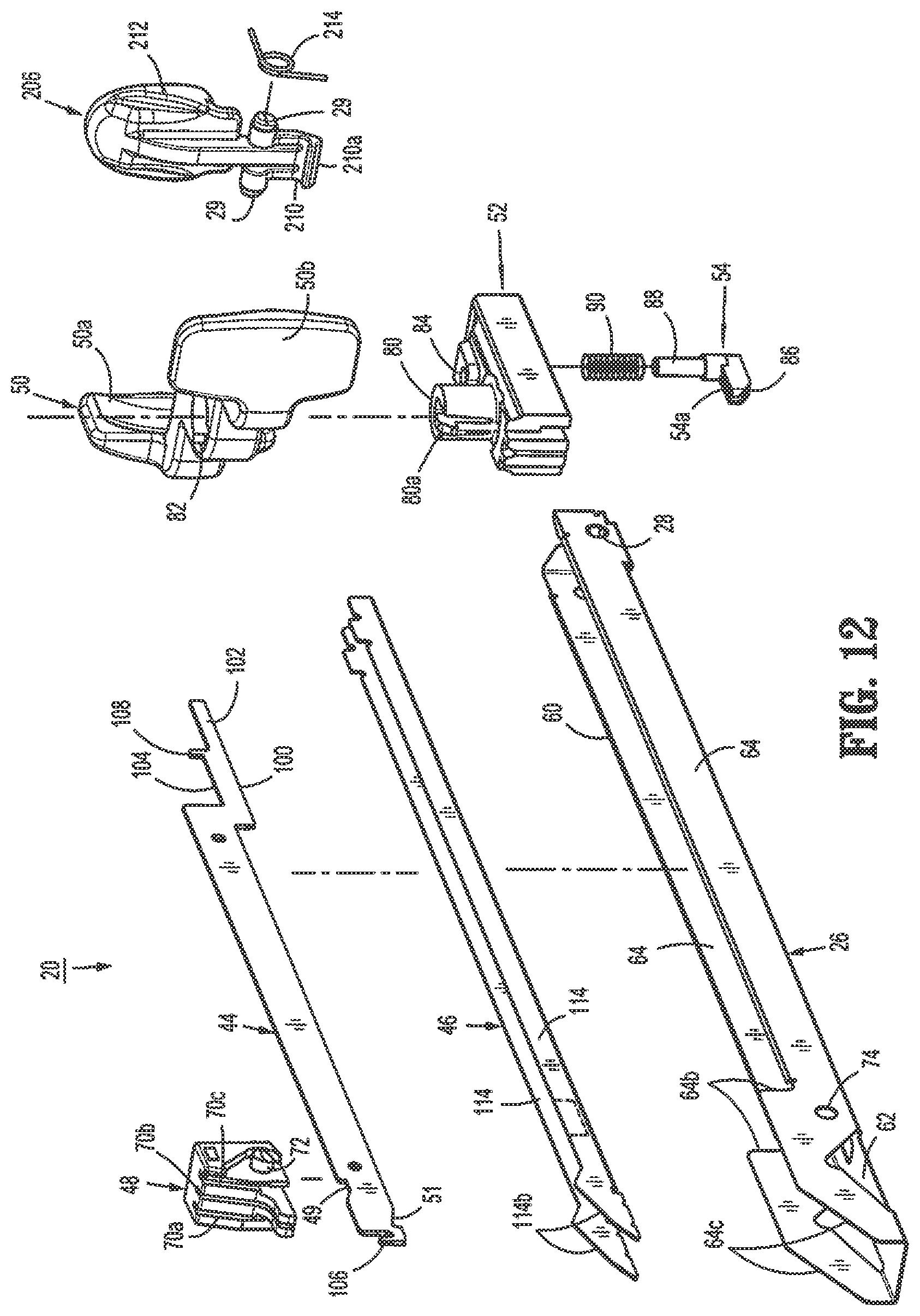
D00014

D00015

D00016

D00017

D00018
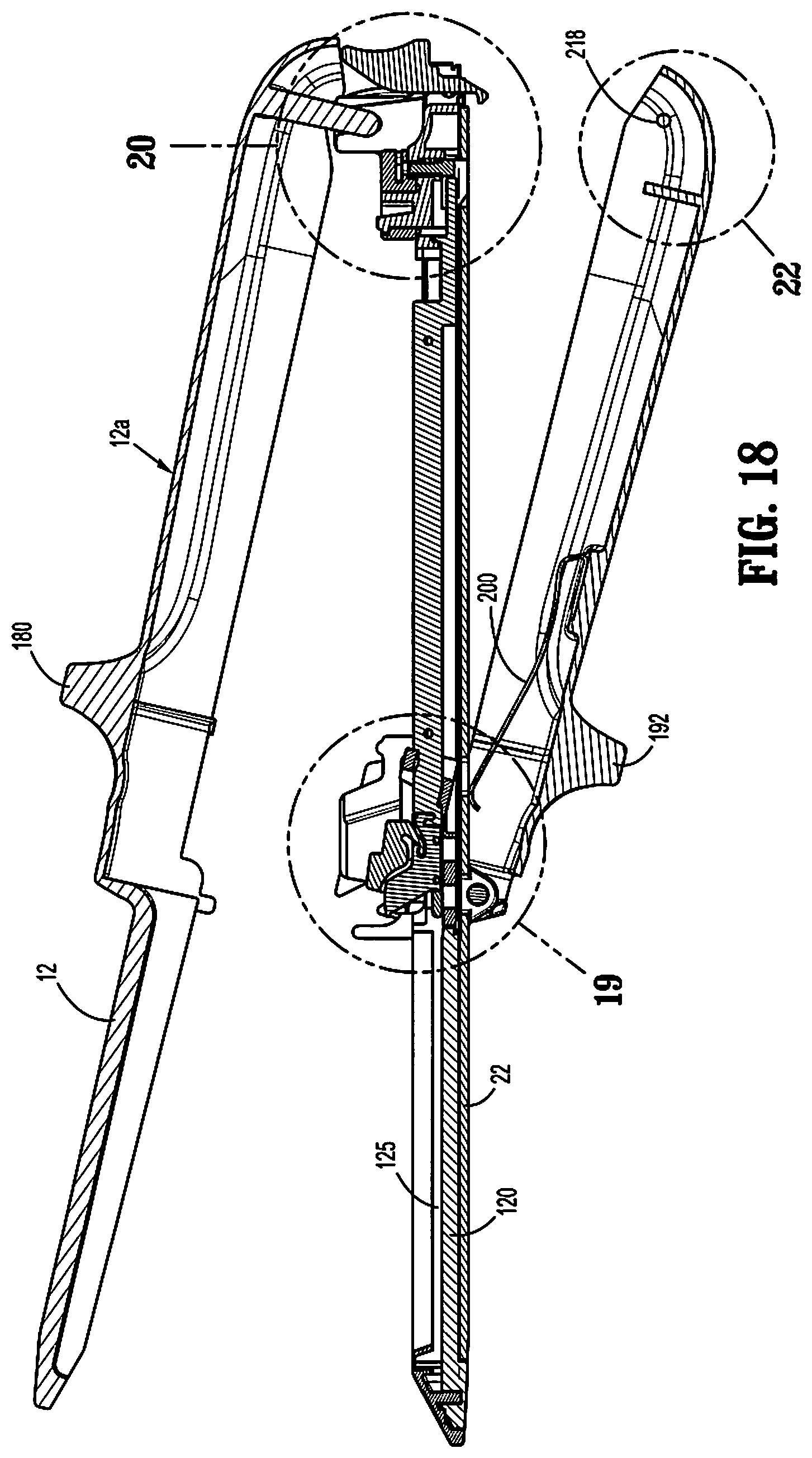
D00019
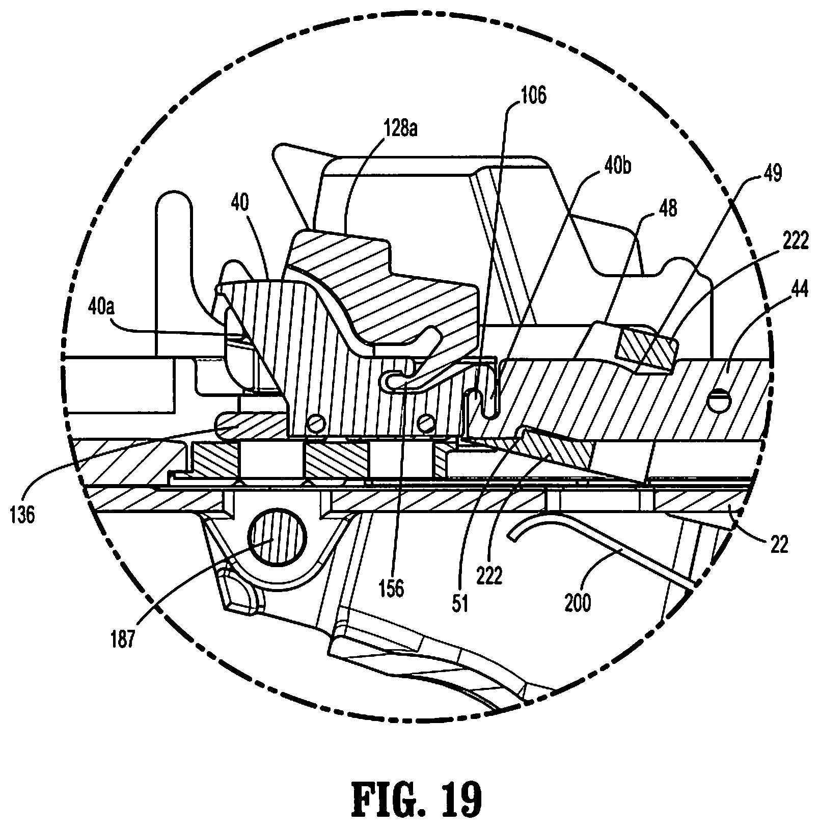
D00020

D00021

D00022

D00023
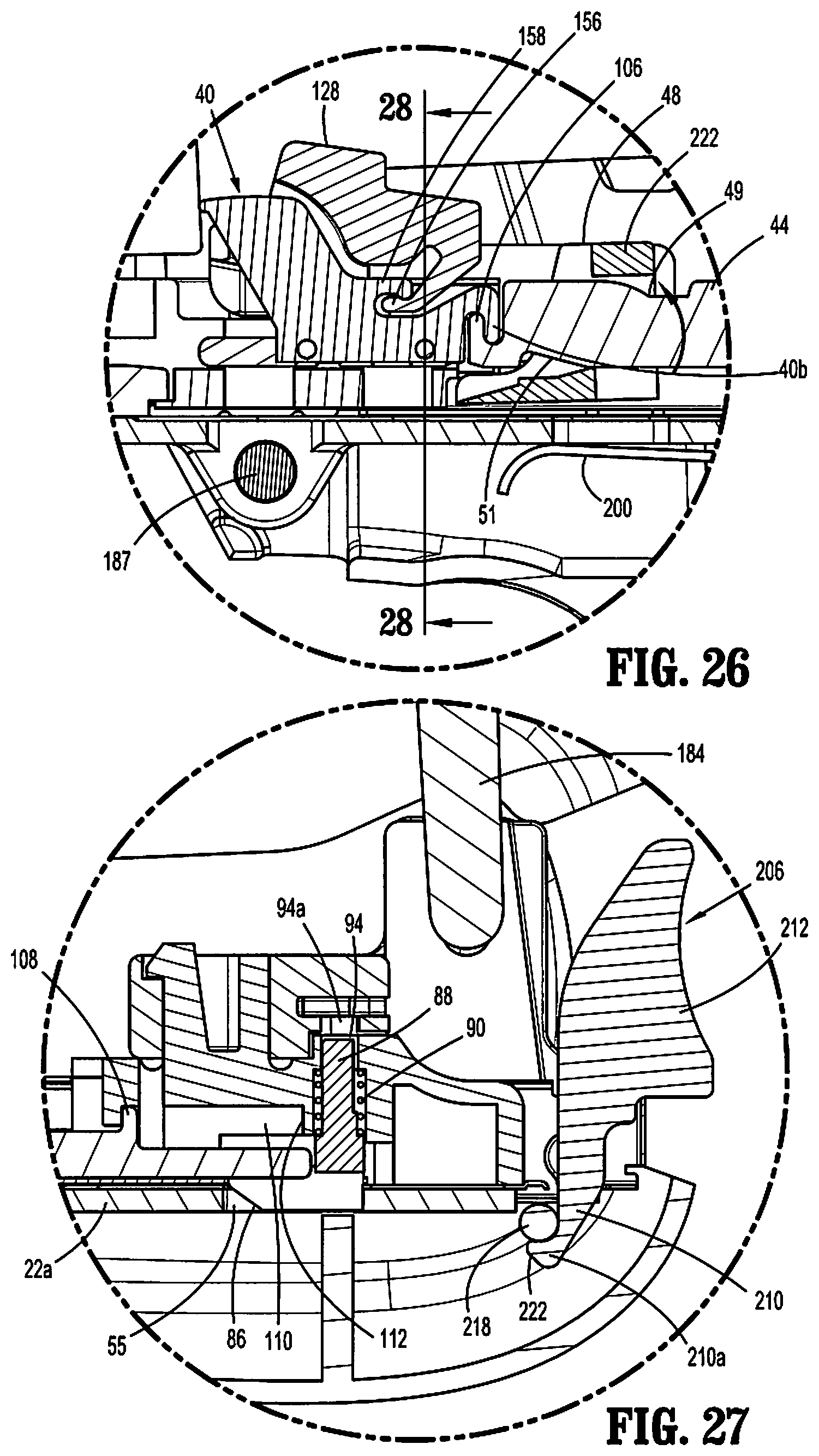
D00024

D00025

D00026

D00027
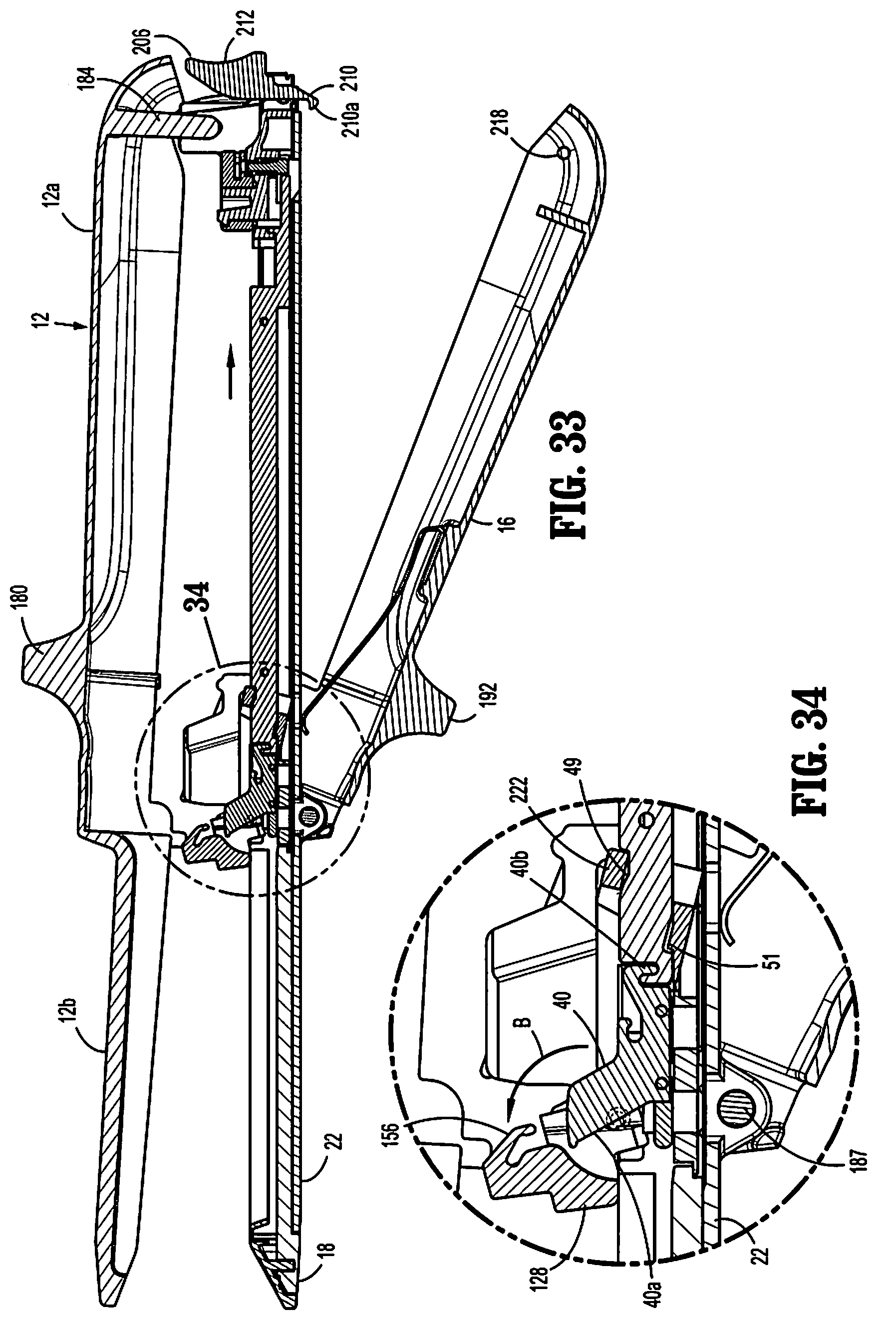
D00028

D00029

D00030
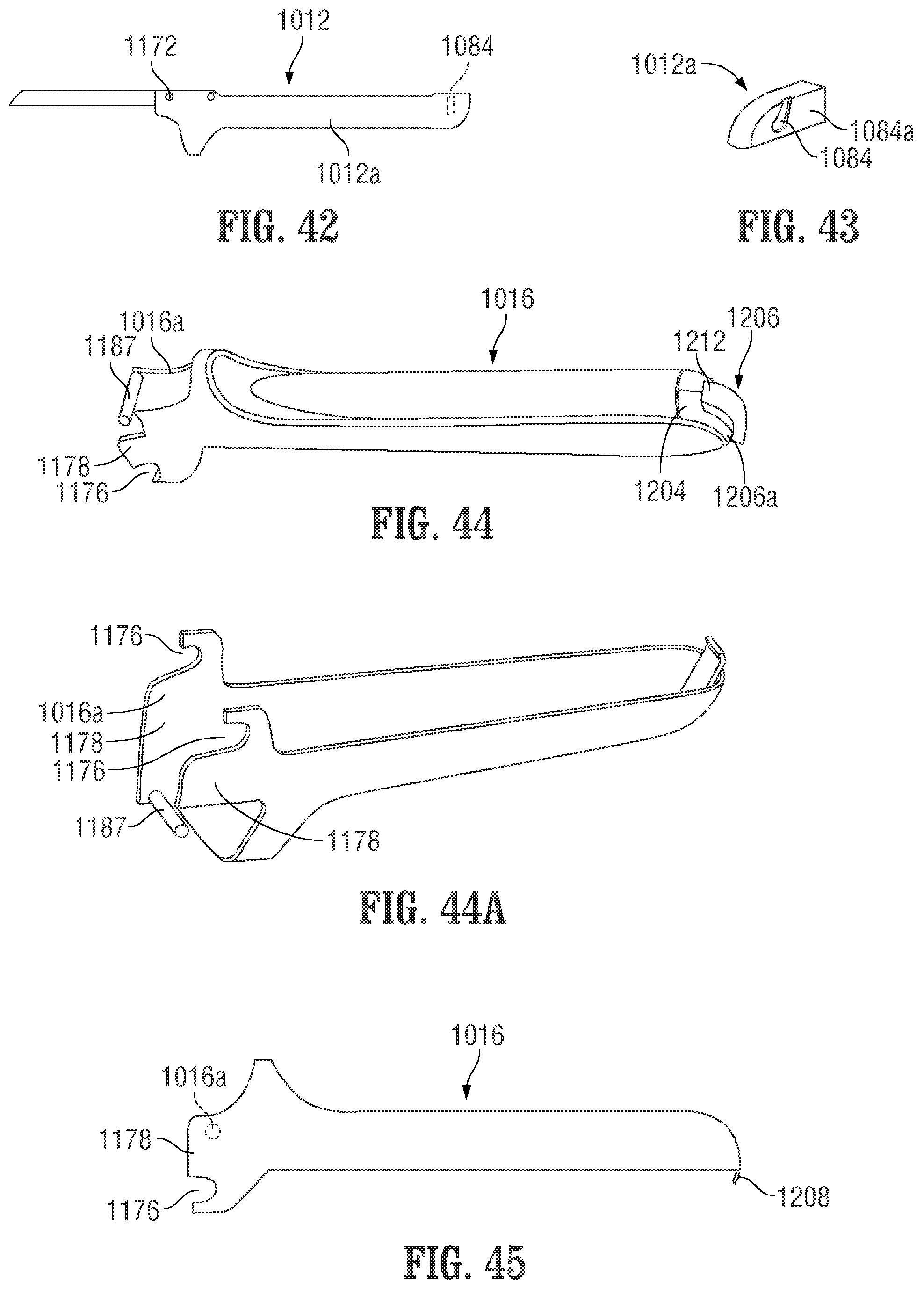
D00031

XML
uspto.report is an independent third-party trademark research tool that is not affiliated, endorsed, or sponsored by the United States Patent and Trademark Office (USPTO) or any other governmental organization. The information provided by uspto.report is based on publicly available data at the time of writing and is intended for informational purposes only.
While we strive to provide accurate and up-to-date information, we do not guarantee the accuracy, completeness, reliability, or suitability of the information displayed on this site. The use of this site is at your own risk. Any reliance you place on such information is therefore strictly at your own risk.
All official trademark data, including owner information, should be verified by visiting the official USPTO website at www.uspto.gov. This site is not intended to replace professional legal advice and should not be used as a substitute for consulting with a legal professional who is knowledgeable about trademark law.