Street lighting communications, control, and special services
Hartman , et al. Dec
U.S. patent number 10,509,101 [Application Number 14/546,486] was granted by the patent office on 2019-12-17 for street lighting communications, control, and special services. The grantee listed for this patent is GENERAL ELECTRIC COMPANY. Invention is credited to Bruce Gordon Barnett, Michael Joseph Dell'Anno, Michael James Hartman, John Erik Hershey, Michael Joseph Mahony, Stanislava Soro.


View All Diagrams
| United States Patent | 10,509,101 |
| Hartman , et al. | December 17, 2019 |
Street lighting communications, control, and special services
Abstract
A smart street lighting system and method employs a plurality of street lights having a luminaire, a luminaire associate and a support pole. A communications module is contained within the luminaire associates and a power line is contained within the support poles. The power line is coupled to the communications module, the luminaire associate and the luminaire, and a steerable millimeter wave radar operatively coupled to the communications module. The communications module operates in a radio frequency network in a frequency range of 57-64 GHz. The steerable millimeter wave radar provides a signal reflected from a target that may be received by one of the luminaire associates within the system. A powerline communications system interfaces with the radio frequency network to provide communications between the communications modules in the street lights and the PLC system.
| Inventors: | Hartman; Michael James (Clifton Park, NY), Barnett; Bruce Gordon (Niskayuna, NY), Hershey; John Erik (Ballston, NY), Mahony; Michael Joseph (Niskayuna, NY), Dell'Anno; Michael Joseph (Niskayuna, NY), Soro; Stanislava (Niskayuna, NY) | ||||||||||
|---|---|---|---|---|---|---|---|---|---|---|---|
| Applicant: |
|
||||||||||
| Family ID: | 53180227 | ||||||||||
| Appl. No.: | 14/546,486 | ||||||||||
| Filed: | November 18, 2014 |
Prior Publication Data
| Document Identifier | Publication Date | |
|---|---|---|
| US 20150346320 A1 | Dec 3, 2015 | |
Related U.S. Patent Documents
| Application Number | Filing Date | Patent Number | Issue Date | ||
|---|---|---|---|---|---|
| 61907090 | Nov 21, 2013 | ||||
| 61907078 | Nov 21, 2013 | ||||
| 61907069 | Nov 21, 2013 | ||||
| 61907114 | Nov 21, 2013 | ||||
| 61907133 | Nov 21, 2013 | ||||
| 61907150 | Nov 21, 2013 | ||||
| 61907168 | Nov 21, 2013 | ||||
| 61907188 | Nov 21, 2013 | ||||
| 61907210 | Nov 21, 2013 | ||||
| Current U.S. Class: | 1/1 |
| Current CPC Class: | H05B 47/105 (20200101); G01S 7/003 (20130101); H05B 47/19 (20200101); H05B 47/10 (20200101); G01S 13/88 (20130101); H05B 47/185 (20200101); H05B 47/115 (20200101); F21S 8/08 (20130101); Y02B 20/40 (20130101); F21V 23/0435 (20130101); F21S 2/00 (20130101); Y02B 20/48 (20130101); F21W 2131/103 (20130101) |
| Current International Class: | H05B 37/02 (20060101); G01S 13/88 (20060101); G01S 7/00 (20060101); F21S 2/00 (20160101); F21S 8/08 (20060101); F21V 23/04 (20060101) |
| Field of Search: | ;315/312,291,294,318 ;362/227 ;340/12.5 |
References Cited [Referenced By]
U.S. Patent Documents
| 4704610 | November 1987 | Smith et al. |
| 4878754 | November 1989 | Homma et al. |
| 5014052 | May 1991 | Obeck |
| 5028129 | July 1991 | Smith |
| 5199044 | March 1993 | Takeuchi et al. |
| 5243185 | September 1993 | Blackwood |
| 5345232 | September 1994 | Robertson |
| 5519692 | May 1996 | Hershey et al. |
| 5519725 | May 1996 | Hershey et al. |
| 5526357 | June 1996 | Jandrell |
| 5557261 | September 1996 | Barbour |
| 5563728 | October 1996 | Allen et al. |
| 5563906 | October 1996 | Hershey et al. |
| 5568507 | October 1996 | Hershey et al. |
| 5568508 | October 1996 | Hershey |
| 5568509 | October 1996 | Hershey et al. |
| 5568522 | October 1996 | Hershey et al. |
| 5682100 | October 1997 | Rossi et al. |
| 5761238 | June 1998 | Ross et al. |
| 5822099 | October 1998 | Takamatsu |
| 5844949 | December 1998 | Hershey et al. |
| 5852243 | December 1998 | Chang et al. |
| 5903594 | May 1999 | Saulnier et al. |
| 6011508 | January 2000 | Perreault et al. |
| 6101214 | August 2000 | Hershey et al. |
| 6122084 | September 2000 | Britz et al. |
| 6288632 | September 2001 | Hoctor et al. |
| 6308134 | October 2001 | Croyle et al. |
| 6346875 | February 2002 | Puckette et al. |
| 6424250 | July 2002 | Puckette, IV et al. |
| 6430210 | August 2002 | McGrath et al. |
| 6433976 | August 2002 | Phillips |
| 6459998 | October 2002 | Hoffman |
| 6504634 | January 2003 | Chan et al. |
| 6522243 | February 2003 | Saulnier et al. |
| 6659715 | December 2003 | Kuesters et al. |
| 6693556 | February 2004 | Jones et al. |
| 6717660 | April 2004 | Bernardo |
| 6943668 | September 2005 | Gaus, Jr. et al. |
| 7175082 | February 2007 | Hoshina |
| 7248149 | July 2007 | Bachelder et al. |
| 7294977 | November 2007 | Eusterbrock et al. |
| 7418346 | August 2008 | Breed et al. |
| 7460787 | December 2008 | Damink et al. |
| 7580705 | August 2009 | Kumar |
| 7629899 | December 2009 | Breed |
| 7646330 | January 2010 | Karr |
| 7817063 | October 2010 | Hawkins et al. |
| 7834555 | November 2010 | Cleland et al. |
| 7855376 | December 2010 | Cantin et al. |
| 7876864 | January 2011 | Conrad et al. |
| 7899621 | March 2011 | Breed et al. |
| 7912645 | March 2011 | Breed et al. |
| 7983685 | July 2011 | Silverstrim et al. |
| 7983836 | July 2011 | Breed |
| 8092032 | January 2012 | Pearse |
| 8138690 | March 2012 | Chemel et al. |
| 8140276 | March 2012 | Walters et al. |
| 8195422 | June 2012 | Wilcox et al. |
| 8227995 | July 2012 | Damink et al. |
| 8232745 | July 2012 | Chemel et al. |
| 8244260 | August 2012 | Silverstrim et al. |
| 8260537 | September 2012 | Breed |
| 8274373 | September 2012 | Nysen |
| 8339069 | December 2012 | Chemel et al. |
| 8368321 | February 2013 | Chemel et al. |
| 8373362 | February 2013 | Chemel et al. |
| 8384312 | February 2013 | Tsai |
| 8436748 | May 2013 | Mimeault et al. |
| 8441214 | May 2013 | Anderson |
| 8442403 | May 2013 | Weaver |
| 8442785 | May 2013 | Walters et al. |
| 8456325 | June 2013 | Sikora |
| 8475002 | July 2013 | Maxik et al. |
| 8641241 | February 2014 | Farmer |
| 8840569 | September 2014 | Flaction et al. |
| 8842009 | September 2014 | Jones |
| 8947296 | February 2015 | Raz et al. |
| 9192026 | November 2015 | Marquardt et al. |
| 9192029 | November 2015 | Marquardt et al. |
| 2002/0141882 | October 2002 | Ingistov et al. |
| 2003/0048499 | March 2003 | Alfano et al. |
| 2005/0017647 | January 2005 | Huang |
| 2005/0047864 | March 2005 | Yamada et al. |
| 2005/0104745 | May 2005 | Bachelder et al. |
| 2005/0187701 | August 2005 | Baney |
| 2007/0063875 | March 2007 | Hoffberg |
| 2007/0085701 | April 2007 | Walters et al. |
| 2007/0201540 | August 2007 | Berkman |
| 2007/0229250 | October 2007 | Recker et al. |
| 2008/0037241 | February 2008 | Von Der Brelie |
| 2008/0072766 | March 2008 | Kobylarz |
| 2008/0122642 | May 2008 | Radtke et al. |
| 2008/0150757 | June 2008 | Hutchison |
| 2008/0238720 | October 2008 | Lee |
| 2009/0002982 | January 2009 | Hu et al. |
| 2009/0033504 | February 2009 | Tsai et al. |
| 2009/0034258 | February 2009 | Tsai et al. |
| 2009/0066540 | March 2009 | Marinakis et al. |
| 2009/0120299 | May 2009 | Rahn et al. |
| 2009/0128328 | May 2009 | Fan |
| 2009/0158739 | June 2009 | Messmer |
| 2009/0164174 | June 2009 | Bears et al. |
| 2009/0167508 | July 2009 | Fadell et al. |
| 2009/0214198 | August 2009 | Takahashi et al. |
| 2009/0268453 | October 2009 | Pearse |
| 2009/0297156 | December 2009 | Nakagawa et al. |
| 2010/0013608 | January 2010 | Petrisor et al. |
| 2010/0029268 | February 2010 | Myer et al. |
| 2010/0115093 | May 2010 | Rice |
| 2010/0148696 | June 2010 | Pabst |
| 2010/0295473 | November 2010 | Chemel et al. |
| 2010/0295474 | November 2010 | Chemel et al. |
| 2010/0295475 | November 2010 | Chemel et al. |
| 2010/0295482 | November 2010 | Chemel et al. |
| 2010/0295943 | November 2010 | Cha et al. |
| 2010/0296285 | November 2010 | Chemel et al. |
| 2010/0301768 | December 2010 | Chemel et al. |
| 2010/0301770 | December 2010 | Chemel et al. |
| 2010/0301771 | December 2010 | Chemel et al. |
| 2010/0301773 | December 2010 | Chemel et al. |
| 2010/0301774 | December 2010 | Chemel et al. |
| 2010/0301834 | December 2010 | Chemel et al. |
| 2010/0302779 | December 2010 | Chemel et al. |
| 2010/0308736 | December 2010 | Hung et al. |
| 2010/0309209 | December 2010 | Hodgins et al. |
| 2011/0001436 | January 2011 | Chemel et al. |
| 2011/0001438 | January 2011 | Chemel et al. |
| 2011/0001626 | January 2011 | Yip et al. |
| 2011/0043035 | February 2011 | Yamada et al. |
| 2011/0069960 | March 2011 | Knapp et al. |
| 2011/0095867 | April 2011 | Ahmad |
| 2011/0115384 | May 2011 | Chatelus |
| 2011/0140950 | June 2011 | Andersson |
| 2011/0156900 | June 2011 | Toda |
| 2011/0215736 | September 2011 | Horbst et al. |
| 2011/0227584 | September 2011 | Beck |
| 2012/0053888 | March 2012 | Staehlin et al. |
| 2012/0062123 | March 2012 | Jarrell et al. |
| 2012/0086560 | April 2012 | Ilyes |
| 2012/0086561 | April 2012 | Ilyes et al. |
| 2012/0126721 | May 2012 | Kuenzler et al. |
| 2012/0136485 | May 2012 | Weber et al. |
| 2012/0139774 | June 2012 | Nagy |
| 2012/0140748 | June 2012 | Carruthers |
| 2012/0154239 | June 2012 | Bar-Sade et al. |
| 2012/0163826 | June 2012 | Schenk et al. |
| 2012/0209505 | August 2012 | Breed et al. |
| 2012/0218101 | August 2012 | Ford |
| 2012/0230696 | September 2012 | Pederson et al. |
| 2012/0245880 | September 2012 | Nabrotzky |
| 2012/0256777 | October 2012 | Smith |
| 2012/0262304 | October 2012 | Cripps |
| 2012/0280825 | November 2012 | Sakakihara |
| 2012/0286673 | November 2012 | Holland et al. |
| 2012/0299721 | November 2012 | Jones |
| 2012/0299755 | November 2012 | Jones |
| 2012/0308239 | December 2012 | Sheth et al. |
| 2012/0309293 | December 2012 | Kummetz et al. |
| 2012/0321321 | December 2012 | Riesebosch |
| 2012/0323474 | December 2012 | Breed et al. |
| 2013/0044488 | February 2013 | Hreish |
| 2013/0057158 | March 2013 | Josefowicz et al. |
| 2013/0063281 | March 2013 | Malaska |
| 2013/0076523 | March 2013 | Kwan et al. |
| 2013/0101003 | April 2013 | Vedantham et al. |
| 2013/0127655 | May 2013 | Kishigami |
| 2013/0140995 | June 2013 | Jones |
| 2013/0144490 | June 2013 | Lord et al. |
| 2013/0169468 | July 2013 | Johnson et al. |
| 2013/0172012 | July 2013 | Zudrell-Koch |
| 2013/0181636 | July 2013 | Agrawal |
| 2013/0214697 | August 2013 | Archenhold |
| 2013/0221858 | August 2013 | Silberstein |
| 2013/0229116 | September 2013 | Van Zeijl |
| 2013/0257284 | October 2013 | VanWagoner et al. |
| 2013/0293117 | November 2013 | Verfuerth |
| 2013/0330172 | December 2013 | Scipio et al. |
| 2013/0346229 | December 2013 | Martin et al. |
| 2014/0055439 | February 2014 | Lee et al. |
| 2014/0085055 | March 2014 | Lee et al. |
| 2014/0124007 | May 2014 | Scipio et al. |
| 2014/0125250 | May 2014 | Wilbur |
| 2014/0175982 | June 2014 | Yao et al. |
| 2014/0191858 | July 2014 | Morgan et al. |
| 2015/0023668 | January 2015 | Spaulding et al. |
| 2015/0173159 | June 2015 | Lin et al. |
| 2015/0319825 | November 2015 | Destine et al. |
| 2016/0094088 | March 2016 | Bjorn et al. |
| 2016/0095182 | March 2016 | Bjorn et al. |
| 101418933 | Apr 2009 | CN | |||
| 102287675 | Dec 2011 | CN | |||
| 102355764 | Feb 2012 | CN | |||
| 102854500 | Jan 2013 | CN | |||
| 102933979 | Feb 2013 | CN | |||
| 0961134 | Dec 1999 | EP | |||
| 1437270 | Jul 2004 | EP | |||
| 2131630 | Dec 2009 | EP | |||
| 2521426 | Nov 2012 | EP | |||
| 2403357 | Dec 2004 | GB | |||
| 05205193 | Aug 1993 | JP | |||
| 2005248607 | Sep 2005 | JP | |||
| 2009025209 | Feb 2009 | JP | |||
| 2009103497 | May 2009 | JP | |||
| 1020060008967 | Jan 2006 | KR | |||
| 1020060102552 | Sep 2006 | KR | |||
| 100986279 | Oct 2010 | KR | |||
| 2005029437 | Mar 2005 | WO | |||
| 2009148466 | Dec 2009 | WO | |||
| 2010079388 | Jul 2010 | WO | |||
| 2011142516 | Nov 2011 | WO | |||
| 2012090142 | Jul 2012 | WO | |||
| 2012140152 | Oct 2012 | WO | |||
| 2013160791 | Oct 2013 | WO | |||
Other References
|
LonMark, The Open Smart Streetlight Platform. cited by applicant . Atlas, "Optical Extinction by Rainfall", Journal of Meteorology, vol. No. 10, pp. 486-488, Dec. 1953. cited by applicant . Noe et al., "Global Positioning System, A Navigation Algorithm for the Low-Cost GPS Receiver", The Institute of Navigation, vol. No. 1, pp. 166-172, 1980. cited by applicant . Proakis, "Spread Spectrum Signals for Digital Communication," in Digital Communications, for an overview of DS theory, pp. 1-27, 1983. cited by applicant . Hershey et al., "Random and Pseudorandom Sequences," Data Transportation and Protection, pp. 259-310, 1986. cited by applicant . "Millimeter Wave Propagation: Spectrum Management Implications" published by the FCC as Bulletin No. 70, Jul. 1997. cited by applicant . Pang et al., "LED Traffic Light as a Communications Device", Proceedings of the International Conference on Intelligent Transportation Systems, pp. 788-793, 1999. cited by applicant . Mimbela et al., "A Summary of Vehicle Detection and Surveillance Technologies Used in Intelligent Transportation Systems", Southwest Technology Development Institute, pp. 1-211, Nov. 30, 2000. cited by applicant . Bullimore, "Controlling Traffic With Radio", IEEE Review, vol. No. 47, Issue No. 1, pp. 40-44, Jan. 2001. cited by applicant . Chao-Qun et al., "Application of Low-voltage Power Line Communication in a City Street Lamp Long-distance Intelligent Monitoring System", Research and Developments, 2006. cited by applicant . Cho et al., "Street Lighting Control Based on LonWorks Power Line Communication", Power Line Communications and Its Applications, pp. 396-398, Apr. 2008. cited by applicant . Awan et al., "Characterization of Fog and Snow Attenuations for Free-Space Optical Propagation", Journal of Communications, vol. No. 4, Issue No. 8, pp. 533-545, Sep. 2009. cited by applicant . Rich, "Light Monitoring System Keeps Glendale, Ariz., Out of the Dark", Government Technology, Oct. 24, 2011. cited by applicant . "Monitoring and Evaluation Protocol for the Field Performance of LED Street Lighting Technologies", Light Savers Accelerating Advanced Outdoor Lighting, Prepared by Toronto Atmospheric Fund in Partnership with Ontario Municipal Street Lighting Focus Group and Ontario Power Authority, pp. 1-32, 2011. cited by applicant . Qian et. al., "Based on PLC and GPRS, ZigBee street lamp wireless control system", Electronic Design Engineering, vol. No. 20, Issue No. 3, Feb. 2012. cited by applicant . Stevens et al., "White Paper--The Benefits of 60 GHz Unlicensed Wireless Communications" as captured by Wayback machine, SUB10 systems.com, pp. 1-10, May 7, 2012. cited by applicant . "Wireless Control and Communication System for LED Luminaires and Other Devices", San Francisco Public Utilities Commission Power Enterprise, pp. 1-15, Jun. 7, 2012. cited by applicant . Zotos et al., "Case study of a dimmable outdoor lighting system with intelligent management and remote control", Telecommunications and Multimedia (TEMU), 2012 International Conference on, pp. 43-48, Jul. 30-Aug. 1, 2012. cited by applicant . After Newtown: A new use for a weapons-detecting radar?, University of Michigan, Apr. 1, 2013. cited by applicant . Lee et al., "Distributed dimming control for LED lighting", Optics Express, vol. No. 21, Issue No. S6, pp. 1-16, Nov. 2013. cited by applicant . Copy of International Search Report and Written Opinion issued in connection with related PCT Application No. PCT/US2014/066954 dated Feb. 26, 2015. cited by applicant . Copy of International Search Report and Written Opinion issued in connection with related PCT Application No. PCT/US2014/066922 dated Feb. 26, 2015. cited by applicant . Copy of International Search Report and Written Opinion issued in connection with related PCT Application No. PCT/US2014/066957 dated Mar. 5, 2015. cited by applicant . Copy of International Search Report and Written Opinion issued in connection with related PCT Application No. PCT/US2014/066917 dated Mar. 5, 2015. cited by applicant . Copy of International Search Report and Written Opinion issued in connection with related PCT Application No. PCT/US2014/066337 dated Mar. 6, 2015. cited by applicant . Copy of International Search Report and Written Opinion issued in connection with corresponding PCT Application No. PCT/US2014/066948 dated Mar. 9, 2015. cited by applicant . Copy of International Search Report and Written Opinion issued in connection with related PCT Application No. PCT/US2014/066942 dated Mar. 20, 2015. cited by applicant . Copy of International Search Report and Written Opinion issued in connection with corresponding PCT Application No. PCT/US2014/066927 dated Feb. 27, 2015. cited by applicant . A copy of US Non-Final Office Action issued in connection with related U.S. Appl. No. 14/484,300 dated Dec. 4, 2015. cited by applicant . A copy of US Non-Final Office Action issued in connection with related U.S. Appl. No. 14/546,256 dated Dec. 30, 2015. cited by applicant . A copy of US Non-Final Office Action issued in connection with related U.S. Appl. No. 14/546,982 dated Feb. 1, 2016. cited by applicant . A copy of US Non-Final Office Action issued in connection with related U.S. Appl. No. 14/546,954 dated Apr. 20, 2016. cited by applicant . A copy of US Non-Final Office Action issued in connection with related U.S. Appl. No. 14/543,892 dated May 9, 2016. cited by applicant . A copy of US Non-Final Office Action issued in connection with related U.S. Appl. No. 14/546,916 dated May 11, 2016. cited by applicant . A copy of Final Office Action issued in connection with related U.S. Appl. No. 14/546,256 dated Jun. 2, 2016. cited by applicant . A copy of Notice of Allowance Office Action issued in connection with related U.S. Appl. No. 14/543,892 dated Aug. 26, 2016. cited by applicant . A copy of Notice of Allowance Office Action issued in connection with related U.S. Appl. No. 14/546,954 dated Sep. 16, 2016. cited by applicant . Chapman et al. "Pulse Compression", Radar Systems Analysis and Design Using MATLAB, pp. 1-37, 2000. cited by applicant . Li-Qing et al. "Positioning System for Freight Vehicle Based on RFID Technology", Computing Technology and Automation, vol. No. 30, Issue No. 1, pp. 39-44, Mar. 2011. cited by applicant . Fernandes et al. "Power Line Communication in Energy Markets", Cypress, Published in Industrial Control DesignLine, pp. 1-15, Aug. 2011. cited by applicant . Jing et al. "Research on GPS /RFID Integration Algorithm Based on the Optimal Selection of RFID Observations", Journal of National University of Defense Technology, vol. No. 34, Issue No. 2, pp. 70-75, Apr. 2012. cited by applicant . Unofficial English Translation of Chinese Office Action issued in connection with related CN Application No. 201480073800.4 dated Apr. 21, 2017. cited by applicant . A copy of US Non-Final Office Action issued in connection with related U.S. Appl. No. 14/546,408 dated May 11, 2017. cited by applicant . Unofficial English Translation of Chinese Office Action issued in connection with related CN Application No. 201480073799.5 dated May 24, 2017. cited by applicant . Unofficial English Translation of Chinese Office Action issued in connection with related CN Application No. 201480073816.5 dated Jun. 2, 2017. cited by applicant . Unofficial English Translation of Chinese Office Action issued in connection with related CN Application No. 201480073801.9 dated Jun. 2, 2017. cited by applicant . A copy of European Search Report and Opinion issued in connection with related EP Application No. 14863951.1 dated Jun. 7, 2017. cited by applicant . A copy of European Search Report and Opinion issued in connection with related EP Application No. 14863466.0 dated Jun. 14, 2017. cited by applicant. |
Primary Examiner: Vu; Jimmy T
Attorney, Agent or Firm: Buckley, Maschoff & Talwalkar, LLC
Parent Case Text
CROSS REFERENCE TO RELATED APPLICATIONS
This application is a non-provisional of and claims the benefit of U.S. Provisional Patent Applications Ser. Nos. 61/907,069, 61/907,078, 61/907,090, 61/907,114, 61/907,133, 61/907,150, 61/907,168, 61/907,188 and 61/907,210 filed on Nov. 21, 2013, the entire contents of which are incorporated herein by reference.
Claims
The invention claimed is:
1. A street lighting system, comprising: a radio frequency (RF) street lighting control system comprising a plurality of communication links in a 57-64 GHz frequency range; a plurality of street lights having a luminaire, a luminaire associate, a support pole, and a power line operatively coupled to the luminaire and the luminaire associate; a communication module within the luminaire associate that is communicatively coupled to the RF street lighting control system; and a steerable millimeter wave radar communicatively coupled to the communications module, wherein the millimeter wave radar has a Doppler processor combined with polarimetric processing capability, further wherein the polarimetric processing is performed on a millimeter wave energy returned to the millimeter wave radar.
2. The system of claim 1, further comprising: a powerline communications (PLC) system coupled to the power line for at least some of the street lights; at least one PLC access port communicatively coupled to the PLC system; and at least one PLC-RF bridge communicatively coupled to the PLC access port and at least one of the communication links.
3. The system of claim 2 wherein the communication links transport from a network that transports data between multiple of the PLC access ports.
4. The system of claim 1 further comprising a power control function that controls power to the street lights using the RF street lighting control system to transmit instructions to the communications module in the luminaire associate.
5. The system of claim 1 wherein the millimeter wave radar beam may be steered towards a target area and a reflected signal returned to the millimeter wave radar.
6. The system of claim 5 wherein the target area is a traffic area and the reflected signal is processed by the Doppler processor to determine traffic conditions.
7. The system of claim 6 further comprising a signal processor that allows the millimeter wave radar with the Doppler processor and polarimetric capability to determine if a person is concealing a metal object.
8. The system of claim 1 wherein a monitoring and control of the street lights is provided by at least one sensor within the luminaire associate that is communicatively coupled to the communication links enabling data transfer between the at least one sensor and the system.
9. The system of claim 8 wherein the at least one sensor is configured to gather a predetermined type of information, wherein the predetermined type of information is selected from at least one of the following: physical integrity of the street light component; operational condition of the street light component; light output; power consumption; assessing environmental conditions; characterizing traffic flow; or inventorying parking space availability.
10. A method for communicating information using smart street lights, comprising: aiming a steerable millimeter wave radar comprising a Doppler processor combined with polarimetric processing capability contained within a street lighting system towards a target area; receiving a reflection of millimeter waves from the target area by a millimeter wave antenna contained within the street lighting system; processing the reflection of millimeter waves with the Doppler processor with polarimetric processing capability; performing polarimetric processing on a millimeter wave energy returned to the millimeter wave radar; and communicating the reflection of millimeter waves to a predetermined destination within the street lighting system using at least one of a plurality of radio frequency (RF) links in a 57-64 GHz frequency range.
11. The method of claim 10, wherein aiming further comprises aiming the steerable millimeter wave radar towards a parking area as the target area; and processing the reflection of millimeter waves to search for open parking spaces.
12. The method of claim 10, wherein the target area is a traffic area and processing further comprises processing the reflection of millimeter waves by the Doppler processor to determine traffic conditions.
13. The method of claim 10, further comprises aiming the steerable millimeter wave radar towards a walking pedestrian as the target area and detecting with the Doppler processor with polarimetric processing if the walking pedestrian is carrying a metallic object.
14. The method of claim 10, wherein communicating further comprises communicating between a first powerline communications (PLC) system and a second PLC system using the RF links.
15. The method of claim 10, further comprising monitoring the street light system using the RF links.
16. The method of claim 10, further comprising transmitting instructions using the RF links to control power distributed to the street light system.
Description
BACKGROUND
As a society moves forward, it is faced with the perennial problem of an aging infrastructure. Any large infrastructure immediately begins to age after completion. Much of the technology used in its construction ages by the time the infrastructure project is finished. As technology moves forward, as social mores evolve and the populace's expectations shift, technology improvements and changes to the infrastructure will be irresistibly mandated. One prominent example of such concerns street lighting.
Street lighting continues to be one of a city's most important and pressing concerns for various reasons. A first reason is to ensure that adequate lighting is provided for the safety of pedestrian, bicyclists, vehicle operators and passengers. A second reason is cost. Conventional lighting is costly to operate and to maintain. It is for this reason that many city infrastructure authorities have decided to either replace or newly install street lighting that is LED-based. Improvement of the monitoring and control of the street lighting is also entailed in upgrading a street lighting architecture.
In general it is not sufficient to just improve a single infrastructure but it is desirable to integrate various and disparate infrastructures in order to create a synergistic result that can be derived from using their various functions in combination with one another. An upgraded infrastructure may also provide "hooks and handles" for interfacing with future additions to the infrastructure, such as accommodating additional functions and public service missions.
There is therefore a need to upgrade street lighting infrastructure and accommodate other societal services with improvements to street lighting architecture.
SUMMARY
A smart street lighting system and method employs a plurality of street lights, each having a luminaire, a luminaire associate, and a support pole, a communications module within each of the luminaire associates, a power line within each of the support poles, the power line is coupled to the communications module, the luminaire associate and the luminaire, and may have a steerable millimeter wave radar operatively coupled to the communications module. The communications module operates in a radio frequency network in a frequency range of 57-64 GHz.
An embodiment allows for assessing the existence of open parking spaces using a millimeter wave radar.
Another embodiment allows for the assessing traffic density and using Doppler information derived from the millimeter wave radar to estimate traffic flow rates.
Another embodiment employs a Doppler-polarimetry mode for the millimeter wave radar to alert of a pedestrian carrying a metallic object.
BRIEF DESCRIPTION OF THE ILLUSTRATIONS
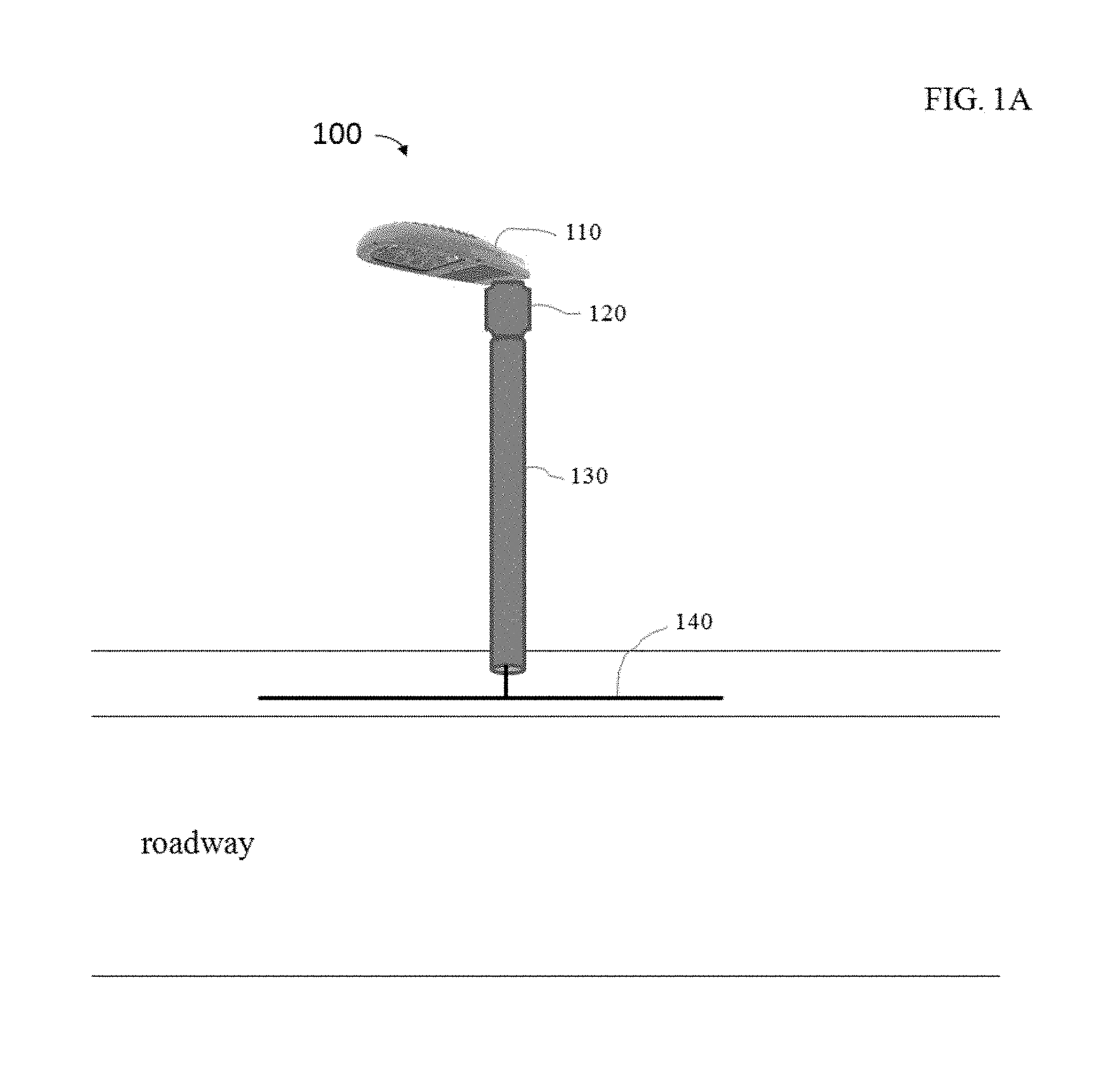
FIG. 1A is an illustration of segmentation within a lighting fixture according to one embodiment.
FIG. 1B is a partial illustration for a communications, control and special service module in a luminaire associate according to one embodiment.
FIG. 2A is an illustration for an example of an radio frequency (RF) communications connected street lighting system with a common powerline according to one embodiment.
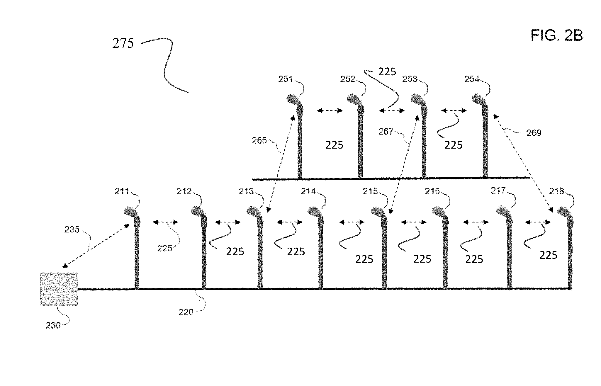
FIG. 2B is an illustration for an example of an RF mesh communications connected street lighting system according to one embodiment.
FIG. 3A is a prior art illustration of oxygen attenuation per kilometer at sea level versus frequency according to one embodiment.
FIG. 3B is a prior art illustration of rain attenuation per kilometer versus rain rate at 60 GHz according to one embodiment.
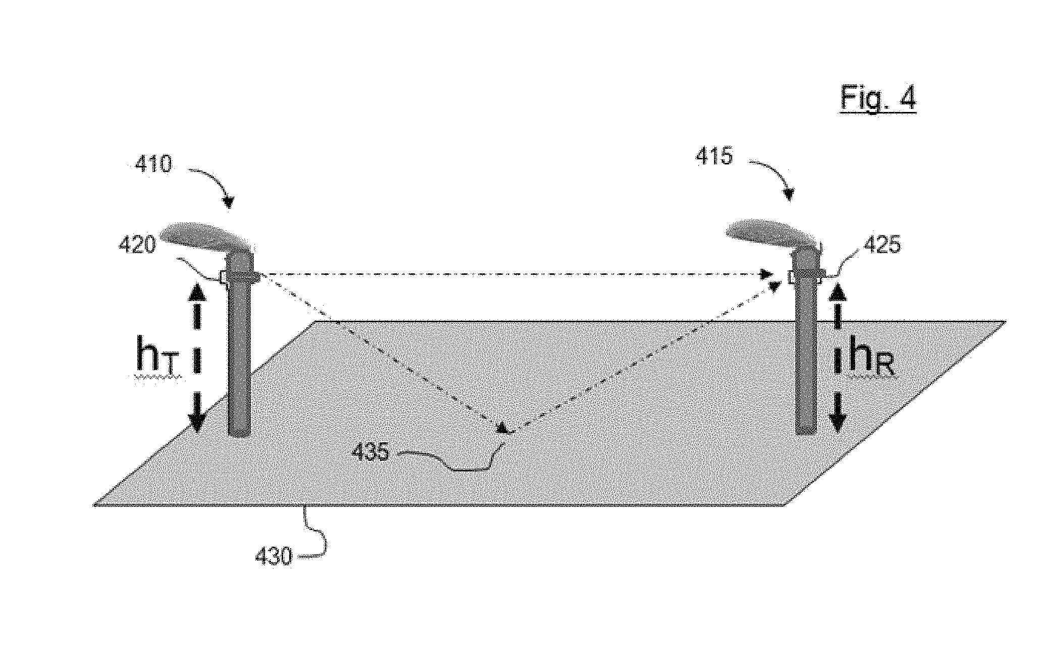
FIG. 4 is an illustration of the geometry for a direct and a reflected wave between two lighting fixtures according to one embodiment.
FIG. 5 is an illustration of an access port to a PLC network according to one embodiment.
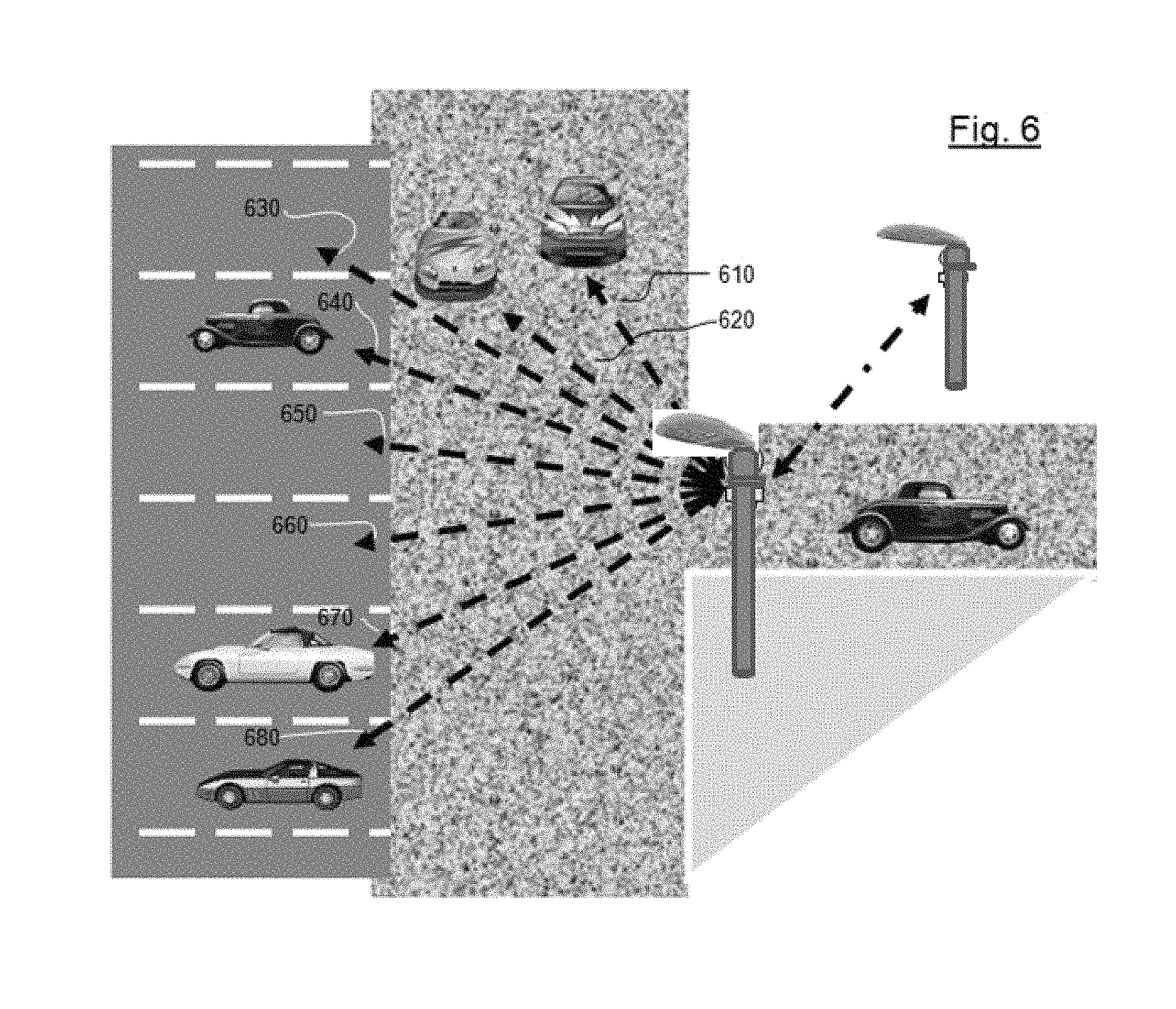
FIG. 6 is an illustration of special services relating to vehicle monitoring according to one embodiment.
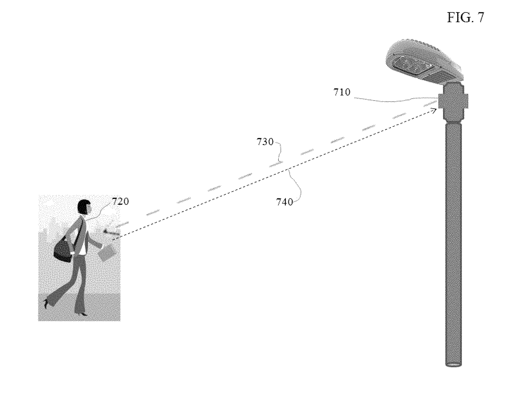
FIG. 7 is an illustration of a steerable millimeter wave radar with Doppler polarimetric capability according to one embodiment.
FIG. 8 is an illustration of an operator remotely operating the steerable millimeter wave radar with Doppler polarimetric capability according to one embodiment.
DETAILED DESCRIPTION
An embodiment of the invention is illustrated by the lighting fixtures of the lighting system shown in FIG. 1A. The lighting fixture 100 comprises a lamp or luminaire 110, supported by a luminaire associate 120. The luminaire associate 120 may include electronic components, electrical circuitry, and mechanical couplings associated with the mounting and control of the luminaire 110. The luminaire associate 120 may be mounted atop a pole 130 that also provides a conduit for the powerline 140 serving the luminaire associate 120 and the luminaire 110.
FIG. 1B is an illustration for an embodiment of a luminaire associate 120 with a communications module 125. The communications module 125 provides communications facilities and may provide control and special service functions, thereby forming a communications, control and special service (C2S2) module 125. In an embodiment, the C2S2 module 125 may provide sophisticated services. These services may be in addition to or in place of communications services.
An embodiment envisions that the C2S2 module 125 may provide a one-way or two-way communication link to an RF network that supports several functions including control of the street lighting system. In an embodiment, the C2S2 module 125 may also monitor the individual luminaire that it is physically mounted upon. Embodiments are envisioned wherein an individual luminaire may use one or more sensors 127 to gather information on that luminaire's condition. Data may be collected detailing information such as the physical integrity of the luminaire, the luminaire's operational condition, such as its light output and power consumption. The C2S2 module 125 may also host various sensors 128 and antennas 126 for performing other infrastructure functions such as, for example and not by way of limitation, assessing environmental conditions, characterizing traffic flow, inventorying a status of parking space availability and determining if a person walking may be concealing a metal object.
FIG. 2A is an illustration for an embodiment of a street lighting system 200 having a common powerline 220. In FIG. 2A each of the eight lighting fixtures 211-218 are connected to powerline 220 which in turn is connected to a power control function subsystem 230. The power control function subsystem 230 is a subsystem of the lighting control system that controls electrical power supplied to the lighting fixtures via power line 220. The power control function subsystem 230 may also function as a gateway to private networks that may be used by the lighting control system or public networks such as the Internet.
Still referring to FIG. 2A, an RF network is shown that may support several functions within the street lighting system 200. Control of the street lighting system 200 may be realized by an interconnection of geographically proximate luminaire associates by RF links 225. An example of links 225 is indicated between luminaire associates of lighting fixtures 211 and 212. It should be noted that the arrows between adjacent luminaire associates 211-218 refer to various RF links 225.
The RF network may support several functions within a mesh network of luminaires including control of the street lighting system. FIG. 2B illustrates another section of a street lighting system comprising lighting fixtures 251-254 in addition to lighting fixtures 211-218 that together form a mesh network 275. The RF network further comprises an RF link 265 between lighting fixtures 213 and 251, an RF link 267 between lighting fixtures 215 and 253, and an RF link 269 between lighting fixtures 218 and 254.
In some embodiments the power control function subsystem 230 may address and control and monitor individual luminaires or groups of luminaires via the RF link 235. The subsystem may receive data concerning one or more luminaires and sensor data provided by the one or more luminaire C2S2 modules. In some embodiments this data may be sent to the power control function subsystem 230 via the power line 220, in other embodiments the data may be transmitted to the power control function subsystem 230 via RF as, for example, by a link 235 from a nearby luminaire associate.
The RF network may support several functions including controlling the street lighting system. An embodiment may make use of the seven GHz of contiguous spectrum (57-64 GHz) that the FCC set aside in 2001 for unlicensed operation. Electromagnetic propagation in this seven GHz slice of spectrum has notable characteristics that may be used for advantage by the RF network in its support of several functions including controlling the street lighting system. The wavelengths are very small, on the order of five millimeters. These short wavelengths will allow high gain antennas to be realized in a significantly small space. These short wavelengths will also allow a steerable antenna, or a plurality of antennas, to be mounted in close proximity to enable beam steering and multi-beam forming.
There is high attenuation of electromagnetic propagation at sea level due to oxygen absorption. As illustrated in FIG. 3A, the rate of oxygen absorption ranges from a minimum of 5 dBs per kilometer to a maximum of 16 dBs per kilometer. The high attenuation due to oxygen absorption will reduce the effects or occurrences of interfering signals. This absorption phenomenon also imparts a security advantage militating against malicious jamming or insinuation of unauthorized signals. Humidity does not appear to be a pronounced absorber; however, rainfall certainly can be a pronounced absorber. FIG. 3B illustrates rain attenuation per kilometer versus rain rate for a 60 GHz transmission. The sensitivity from absorption due to the rainfall rate per kilometer of a path length can be used to sense the presence of rain and estimate the rainfall rate. This may be useful information to gather for controlling the illumination times and intensities of luminaires within the rainfall affected areas.
Notwithstanding oxygen and rainfall absorption, it is expected that received power from a transmitter may drop off as approximately the inverse of distance squared rather than exhibit a higher rate of drop off, such as the inverse fourth power that is noted in some cellular communication situations. The rapid rate of drop off of received power from a transmitter, noted in some cellular communication situations, is due to direct and reflected rays negatively interfering with each other. The breakpoint distance is defined as the distance beyond which the inverse fourth power law may apply and at the extremely high frequencies of millimeter wave communications, the breakpoint distance of a two-ray (direct and reflected) model may be quite large. The breakpoint distance is here denoted as d.sub.BP and is found by computing d.sub.BP=4h.sub.Th.sub.R/.lamda. where .lamda. is the wavelength and h.sub.T and h.sub.R are the respective transmitter and receiver antenna heights.
FIG. 4 illustrates the geometry for two lighting fixtures 410, 415 having respective C2S2 modules 420, 425. As seen in FIG. 4 a direct RF wave between C2S2 420 and C2S2 425 and a reflected RF wave off of the street 430 at location 435. For an example, consider a 60 GHz transmission between two C2S2s, 420 and 425, having antennas 20 meters above the street. The frequency of 60 GHz is approximately in the middle of the unlicensed band of the embodiment of the RF network, 57-64 GHz. For this frequency and for the antenna heights of the embodiment, d.sub.BP=42020/0.005 meters=320 kilometers. This calculated breakpoint distance far exceeds the expected inter-lighting fixture spacing distance in a street lighting system. The fact that the breakpoint distance, beyond which the attenuation rate moves from that of free space, which is the inverse of distance squared, to that of inverse of distance to the fourth power, is very large provides confidence that line of sight millimeter wave communications should function well in the dielectric canyons of a city with tall buildings facing its streets.
In one embodiment, the RF network may function as a data transport network for transporting data to and from one or more access ports serving powerline communications (PLC) systems. The PLC systems may be used to carry modulated data via a powerline and constructed on a multi-carrier system such as Orthogonal Frequency-Division Multiplexing (OFDM), Geometric Harmonic Modulation (GHM), or other suitable genre of PLC modulation. PLC systems may communicate with the RF network through the use of powerline-RF bridges and RF links to a C2S2 module. Powerline-RF Bridges allow signals on one powerline to be communicated to another powerline through radio frequency communications. A powerline-RF bridge may operate in various modes according to differing embodiments. Below are two modes of operation that Powerline-RF Bridges may employ.
In the first mode of powerline-RF bridge operation, a first PLC signal is received and demodulated by a first powerline-RF bridge and the data carried by the first PLC signal is recovered. The data carried by the first PLC signal is then transmitted to a first C2S2 module by an RF link between the first powerline-RF bridge and the first C2S2 module. The data travels on the RF network to a second C2S2 module that has an RF link to a second powerline-RF bridge. When the data arrives at the second C2S2 module, the data carried by the first PLC signal is transmitted on the RF link between the second C2S2 module and the second powerline-RF bridge. The second powerline-RF bridge modulates the data carried by the first PLC signal onto a second PLC signal which is placed onto a second PLC system.
In the second mode of powerline-RF bridge operation, a PLC signal is received by a first powerline-RF bridge and the PLC signal transmitted to a first C2S2 module by an RF link between the first powerline-RF bridge and the first C2S2 module. The PLC signal travels on the RF network to a second C2S2 module that has an RF link to a second powerline-RF bridge. When the PLC signal arrives at the second C2S2 module, the PLC signal is transmitted on the RF link between the second C2S2 module and the second powerline-RF bridge. The second powerline-RF bridge places the PLC signal onto a PLC system of the same genre of PLC modulation as the PLC signal that was received by the first powerline-RF bridge.
FIG. 5 illustrates an access port 510 to a PLC network. The access port 510 as shown in FIG. 5 is an electrical wall socket. This illustrates the versatility of the embodiments discussed herein. The access port 510 may also be a powerline for another set of street lights carrying a PLC signal or a power system within a dwelling could carry the PLC signal to access port 510. The PLC signal from the access port 510 is connected by connector 515 to a powerline-RF bridge 520. The powerline-RF bridge 520 communicates with a C2S2 module 540 by an RF link 530. The RF network transports the PLC signal or PLC data depending upon the mode of the powerline-RF bridge 520 to another C2S2 module 545 via RF link 535 and then to C2S2 module 550 via RF link 555 where the PLC signal or the PLC data is transmitted by an RF link 570 to a powerline-RF bridge 560.
In one embodiment of the special services provided, the C2S2 module may be equipped with a millimeter wave radar having a steerable beam employing Doppler measurement capability and signal processing. The millimeter wave radar beam may be steered in the direction of traffic and a reflected signal returned to the radar resulting from an interaction of the illuminating radar beam and the illuminated traffic. The returned signal may be processed and used to monitor traffic flow characterized by traffic density and the speed of one or more vehicles. This service may be performed by the C2S2 module of a luminaire as depicted in FIG. 6. A single millimeter wave antenna may be provided to the C2S2 module of a luminaire so that the antenna transmit aperture can illuminate the roadway and receive a return signal from the electromagnetic energy reflected from vehicles illuminated by the millimeter wave. This is depicted by the rays 610 and 620. The returned signal may be processed using signal processing techniques that are known in the art to estimate traffic conditions such as the number of vehicles in a stretch of the monitored roadway and also the average speeds of those vehicles.
In another embodiment of the special services provided, the C2S2 module functions as a millimeter wave radar to audit the status of parking spaces for vehicle occupancy. For this embodiment the C2S2 module is fitted with a plurality of antennas or a steerable antenna, both of which are generally referred to herein as "a steerable antenna", and the millimeter wave radar steers the millimeter wave beam towards particular parking spots 630-680. A vacant parking space will return a signal significantly different from the signal returned from an occupied parking space. The return signal can be processed using signal processing techniques well known in the art to estimate whether or not there is a vehicle in the particular parking spot.
In yet another embodiment, the C2S2 module may also serve a security function. Professor Kamal Sarabandi suggested that a millimeter wave radar with Doppler and polarization capability combined with signal processing may be used in the security arts. His research was reported by in an article entitled "After Newtown: A new use for a weapons-detecting radar?" the article was published in Science Daily Apr. 1, 2013, and can be found on the internet at the location below. http://www.sciencedaily.com/releeases/2013/04/130401112040.htm?utm_source- =feedburner&ut m_medium=feed&utm_campaign=Feed%3A+sciencedaily+%28Latest+Science+News+--- +ScienceDaily%29.
By combining millimeter wave radar with Doppler processing and a polarimetric capability, it is envisioned that the C2S2 may be used for remotely assessing the probability that a walking person may be carrying a concealed metal object. The method uses the Doppler mode of the millimeter wave radar to identify a person walking, shaping the millimeter wave radar's beam so that the millimeter wave radar return from the person walking may be segmented into returns from portions of the walking person's body and then performing polarimetric processing of that segment of the walking person's return that most likely corresponds to the walking person's torso.
FIG. 7 illustrates a C2S2 module 710 that is equipped with a steerable millimeter wave radar having Doppler polarimetric capability. A walking target 720 is identified by illuminating the walking target 720 with the steered and shaped millimeter wave radar beam 730. Polarimetric processing is then performed on the millimeter wave energy 740 that is returned to the millimeter wave radar. FIG. 8 illustrates an operator 820 with a control and display console 830 connected to the RF network through an RF link 810. The operator 820 is controlling the steerable millimeter wave radar with Doppler polarimetric capability included within C2S2 850 to investigate a walking target 720. The polarimetric processing indicates the presence of a concealed metallic object 840.
An exemplary technical effect of the methods and systems described herein includes: (a) generating a melt pool based on the build parameters of the component; (b) detecting an optical signal generated by the melt pool to measure the size or the temperature of the melt pool; and (c) modifying the build parameters in real-time based on the size or the temperature of the melt pool to achieve a desired physical property of the component.
Some embodiments involve the use of one or more electronic or computing devices. Such devices typically include a processor or controller, such as, without limitation, a general purpose central processing unit (CPU), a graphics processing unit (GPU), a microcontroller, a field programmable gate array (FPGA), a reduced instruction set computer (RISC) processor, an application specific integrated circuit (ASIC), a programmable logic circuit (PLC), and/or any other circuit or processor capable of executing the functions described herein.
The methods described herein may be encoded as executable instructions embodied in a computer readable medium, including, without limitation, a storage device, and/or a memory device. Such instructions, when executed by a processor, cause the processor to perform at least a portion of the methods described herein. The above examples are exemplary only, and thus are not intended to limit in any way the definition and/or meaning of the term processor.
Exemplary embodiments for enhancing the build parameters for making additive manufactured components are described above in detail. The apparatus, systems, and methods are not limited to the specific embodiments described herein, but rather, operations of the methods and components of the systems may be utilized independently and separately from other operations or components described herein. For example, the systems, methods, and apparatus described herein may have other industrial or consumer applications and are not limited to practice with electronic components as described herein. Rather, one or more embodiments may be implemented and utilized in connection with other industries.
Although specific features of various embodiments of the invention may be shown in some drawings and not in others, this is for convenience only. In accordance with the principles of the invention, any feature of a drawing may be referenced or claimed in combination with any feature of any other drawing.
This written description uses examples to disclose the invention, including the best mode, and to enable any person skilled in the art to practice the invention, including making and using any devices or systems and performing any incorporated methods. The patentable scope of the invention is defined by the claims, and may include other examples that occur to those skilled in the art. Such other examples are intended to be within the scope of the claims if they have structural elements that do not differ from the literal language of the claims, or if they include equivalent structural elements with insubstantial differences from the literal language of the claims.
* * * * *
References
D00000
D00001
D00002
D00003
D00004
D00005
D00006
D00007
D00008
D00009
D00010
D00011
XML
uspto.report is an independent third-party trademark research tool that is not affiliated, endorsed, or sponsored by the United States Patent and Trademark Office (USPTO) or any other governmental organization. The information provided by uspto.report is based on publicly available data at the time of writing and is intended for informational purposes only.
While we strive to provide accurate and up-to-date information, we do not guarantee the accuracy, completeness, reliability, or suitability of the information displayed on this site. The use of this site is at your own risk. Any reliance you place on such information is therefore strictly at your own risk.
All official trademark data, including owner information, should be verified by visiting the official USPTO website at www.uspto.gov. This site is not intended to replace professional legal advice and should not be used as a substitute for consulting with a legal professional who is knowledgeable about trademark law.