Apparatus and methods for coating medical devices
Chappa , et al. Dec
U.S. patent number 10,507,309 [Application Number 16/160,425] was granted by the patent office on 2019-12-17 for apparatus and methods for coating medical devices. This patent grant is currently assigned to Surmodics, Inc.. The grantee listed for this patent is Surmodics, Inc.. Invention is credited to Andrew G. Bach, Ralph A. Chappa, Mark MacGregor.


View All Diagrams
| United States Patent | 10,507,309 |
| Chappa , et al. | December 17, 2019 |
Apparatus and methods for coating medical devices
Abstract
Embodiments herein include apparatus and methods for coating medical devices. In an embodiment, a coating apparatus is included having a coating application unit including a movement restriction structure, a fluid applicator having a lengthwise major axis, a fluid distribution bar having a body angled with respect to the major lengthwise axis of the fluid applicator between 0 and 20 degrees, a rotation mechanism and an axial motion mechanism. The axial motion mechanism configured to cause movement of at least one of the coating application unit and the rotation mechanism with respect to one another. Other embodiments are also included herein.
| Inventors: | Chappa; Ralph A. (Ham Lake, MN), Bach; Andrew G. (Edina, MN), MacGregor; Mark (St. Paul, MN) | ||||||||||
|---|---|---|---|---|---|---|---|---|---|---|---|
| Applicant: |
|
||||||||||
| Assignee: | Surmodics, Inc. (Eden Prairie,
MN) |
||||||||||
| Family ID: | 51841548 | ||||||||||
| Appl. No.: | 16/160,425 | ||||||||||
| Filed: | October 15, 2018 |
Prior Publication Data
| Document Identifier | Publication Date | |
|---|---|---|
| US 20190151629 A1 | May 23, 2019 | |
Related U.S. Patent Documents
| Application Number | Filing Date | Patent Number | Issue Date | ||
|---|---|---|---|---|---|
| 15783554 | Oct 13, 2017 | 10099041 | |||
| 14272204 | May 7, 2014 | 9827401 | |||
| 13906599 | May 31, 2013 | 9308355 | |||
| 61654403 | Jun 1, 2012 | ||||
| 61661684 | Jun 19, 2012 | ||||
| 61820223 | May 7, 2013 | ||||
| 61829375 | May 31, 2013 | ||||
| 61875524 | Sep 9, 2013 | ||||
| Current U.S. Class: | 1/1 |
| Current CPC Class: | B05B 13/0442 (20130101); A61M 25/1029 (20130101); A61M 2025/1031 (20130101) |
| Current International Class: | B05B 13/04 (20060101); A61M 25/10 (20130101) |
References Cited [Referenced By]
U.S. Patent Documents
| 273410 | March 1883 | Wadleigh et al. |
| 554114 | February 1896 | Evertz |
| 1281672 | October 1918 | Schorn |
| 1866100 | July 1932 | Hach |
| 2253019 | August 1941 | Crepeau |
| 2330880 | October 1943 | Gladfelter et al. |
| 2335116 | January 1950 | Hansen |
| 2493787 | January 1950 | Torretti |
| 2781280 | January 1957 | Miller |
| 2821158 | January 1958 | Brown |
| 3198170 | August 1965 | Toshio |
| 3318281 | May 1967 | Plegat |
| 3348964 | October 1967 | Good et al. |
| 3416530 | December 1968 | Ness |
| 3502494 | March 1970 | Ishiwata et al. |
| 3625214 | December 1971 | Higuchi |
| 3645773 | February 1972 | Herzhoff et al. |
| 3663292 | May 1972 | Herzhoff et al. |
| 3669917 | June 1972 | Ando et al. |
| 3699917 | October 1972 | Deverse et al. |
| 3723120 | March 1973 | Hummel et al. |
| 3837805 | September 1974 | Boucher |
| 3935896 | February 1976 | Tegtmeier et al. |
| 3936549 | February 1976 | Kohler et al. |
| 3963069 | June 1976 | Marti et al. |
| 3966120 | June 1976 | Furgalus et al. |
| 4000745 | January 1977 | Goldberg |
| 4016306 | April 1977 | Miyagawa et al. |
| 4051805 | October 1977 | Waldrum |
| 4060116 | November 1977 | Frailly |
| 4069307 | January 1978 | Higuchi et al. |
| 4073335 | February 1978 | Fort et al. |
| 4075975 | February 1978 | Oswald |
| 4082870 | April 1978 | Yenni |
| 4144317 | March 1979 | Higuchi et al. |
| 4146036 | March 1979 | Dutcher et al. |
| 4148934 | April 1979 | Baker |
| 4153201 | May 1979 | Berger et al. |
| 4174678 | November 1979 | Van Den Bergh |
| 4195637 | April 1980 | Gruntzig et al. |
| 4196231 | April 1980 | Hubers |
| 4206756 | June 1980 | Grossan |
| 4209019 | June 1980 | Dutcher et al. |
| 4240373 | December 1980 | Anger |
| 4257343 | March 1981 | Kullander |
| 4289089 | September 1981 | Tacke et al. |
| 4292965 | October 1981 | Nash |
| 4300557 | November 1981 | Refojo et al. |
| 4301968 | November 1981 | Berger et al. |
| 4304765 | December 1981 | Shell et al. |
| 4337896 | July 1982 | Berger et al. |
| 4352459 | October 1982 | Berger et al. |
| 4364879 | December 1982 | Gut et al. |
| 4375820 | March 1983 | Vinarcsik et al. |
| 4415654 | November 1983 | Pohl |
| 4475972 | October 1984 | Wong |
| 4503802 | March 1985 | Keller et al. |
| 4541564 | September 1985 | Berger et al. |
| 4544626 | October 1985 | Sullivan |
| 4567934 | February 1986 | Nakao et al. |
| 4572451 | February 1986 | Ikeda et al. |
| 4575330 | March 1986 | Hull |
| 4603058 | July 1986 | Adams |
| 4616593 | October 1986 | Kawamura et al. |
| 4622917 | November 1986 | Schramm |
| 4638045 | January 1987 | Kohn et al. |
| 4655393 | April 1987 | Berger |
| 4678466 | July 1987 | Rosenwald |
| 4723708 | February 1988 | Berger et al. |
| 4743252 | May 1988 | Martin, Jr. et al. |
| 4764377 | August 1988 | Goodson |
| 4819661 | April 1989 | Heil, Jr. et al. |
| 4824017 | April 1989 | Mansfield |
| 4853224 | August 1989 | Wong |
| 4863457 | September 1989 | Lee et al. |
| 4892736 | January 1990 | Goodson |
| 4927741 | May 1990 | Garth et al. |
| 4953564 | September 1990 | Berthelsen |
| 4959217 | September 1990 | Sanders et al. |
| 4971895 | November 1990 | Sullivan |
| 4972848 | November 1990 | Di Domenico et al. |
| 4978067 | December 1990 | Berger et al. |
| 4988883 | January 1991 | Oppawsky |
| 4997652 | March 1991 | Wong et al. |
| 5002067 | March 1991 | Berthelsen et al. |
| 5002582 | March 1991 | Guire et al. |
| 5003992 | April 1991 | Holleman et al. |
| 5036634 | August 1991 | Lessard et al. |
| 5041089 | August 1991 | Mueller et al. |
| 5049404 | September 1991 | Kisler et al. |
| 5069940 | December 1991 | Wenrick |
| 5071337 | December 1991 | Heller et al. |
| 5076285 | December 1991 | Hess et al. |
| 5076974 | December 1991 | Modrek et al. |
| 5087246 | February 1992 | Smith |
| 5098443 | March 1992 | Parel et al. |
| 5102402 | April 1992 | Dror et al. |
| 5114719 | May 1992 | Sabel et al. |
| 5120312 | June 1992 | Wigness et al. |
| 5164188 | November 1992 | Wong |
| 5183509 | February 1993 | Brown et al. |
| 5207343 | May 1993 | Bogadi |
| 5219120 | June 1993 | Ehrenberg et al. |
| 5219690 | June 1993 | Hammond |
| 5221698 | June 1993 | Amidon et al. |
| 5229128 | July 1993 | Haddad et al. |
| 5246867 | September 1993 | Lakowicz et al. |
| 5248752 | September 1993 | Argyropoulos et al. |
| 5254164 | October 1993 | Masahumi |
| 5255693 | October 1993 | Dutcher et al. |
| 5300108 | April 1994 | Rebell et al. |
| 5300114 | April 1994 | Gwon |
| 5304121 | April 1994 | Sahatjian |
| 5310559 | May 1994 | Shah et al. |
| 5314419 | May 1994 | Pelling et al. |
| 5318587 | June 1994 | Davey |
| 5324325 | June 1994 | Moaddeb |
| 5344298 | September 1994 | Hull |
| 5364343 | November 1994 | Apolet et al. |
| 5372577 | December 1994 | Ungerleider |
| 5378475 | January 1995 | Smith et al. |
| 5382234 | January 1995 | Cornelius et al. |
| 5385148 | January 1995 | Lesh et al. |
| 5387247 | February 1995 | Vallana et al. |
| 5395618 | March 1995 | Darougar et al. |
| 5405376 | April 1995 | Mulier et al. |
| 5405631 | April 1995 | Rosenthal |
| 5413638 | May 1995 | Bernstein, Jr. et al. |
| 5414075 | May 1995 | Swan et al. |
| 5421979 | June 1995 | Stevenson |
| 5423777 | June 1995 | Tajiri et al. |
| 5431649 | July 1995 | Mulier et al. |
| 5437656 | August 1995 | Shikani et al. |
| 5443505 | August 1995 | Wong et al. |
| 5447724 | September 1995 | Helmus et al. |
| 5449382 | September 1995 | Dayton |
| 5464650 | November 1995 | Berg et al. |
| 5466233 | November 1995 | Weiner et al. |
| 5472436 | December 1995 | Fremstad |
| 5476511 | December 1995 | Gwon et al. |
| 5501735 | March 1996 | Pender |
| 5501856 | March 1996 | Ohtori et al. |
| 5512055 | April 1996 | Domb et al. |
| 5525348 | June 1996 | Whitbourne et al. |
| 5527389 | June 1996 | Rosenblum et al. |
| 5545208 | August 1996 | Wolff et al. |
| 5556633 | September 1996 | Haddad et al. |
| 5571089 | November 1996 | Crocker |
| 5578075 | November 1996 | Dayton |
| 5582616 | December 1996 | Bolduc et al. |
| 5591227 | January 1997 | Dinh et al. |
| 5605696 | February 1997 | Eury et al. |
| 5609629 | March 1997 | Fearnot et al. |
| 5618568 | April 1997 | Krupa et al. |
| 5624411 | April 1997 | Tuch |
| 5624975 | April 1997 | Valencia |
| 5626919 | May 1997 | Chapman et al. |
| 5630879 | May 1997 | Eichmann et al. |
| 5637113 | June 1997 | Tartaglia et al. |
| 5637460 | June 1997 | Swan et al. |
| 5643362 | July 1997 | Garves |
| 5645592 | July 1997 | Nicolais et al. |
| 5651986 | July 1997 | Brem |
| 5656332 | August 1997 | Saito et al. |
| 5658387 | August 1997 | Reardon et al. |
| 5673473 | October 1997 | Johnson et al. |
| 5679400 | October 1997 | Tuch |
| 5714360 | February 1998 | Swan et al. |
| 5725493 | March 1998 | Avery et al. |
| 5743964 | April 1998 | Pankake |
| 5766242 | June 1998 | Wong et al. |
| 5773019 | June 1998 | Ashton et al. |
| 5776101 | July 1998 | Goy |
| 5788772 | August 1998 | Kunieda et al. |
| 5807331 | September 1998 | Den Heijer et al. |
| 5807395 | September 1998 | Mulier et al. |
| 5810836 | September 1998 | Hussein et al. |
| 5824072 | October 1998 | Wong |
| 5830173 | November 1998 | Avery et al. |
| 5833715 | November 1998 | Vachon et al. |
| 5833891 | November 1998 | Subramaniam et al. |
| 5837008 | November 1998 | Berg et al. |
| 5837088 | November 1998 | Palmgren et al. |
| 5837313 | November 1998 | Ding et al. |
| 5849359 | December 1998 | Burns et al. |
| 5858435 | January 1999 | Gallo |
| 5868697 | February 1999 | Richter et al. |
| 5877224 | March 1999 | Brocchini et al. |
| 5882336 | March 1999 | Janacek |
| 5882405 | March 1999 | Kish et al. |
| 5886026 | March 1999 | Hunter et al. |
| 5897911 | April 1999 | Loeffler |
| 5904144 | May 1999 | Hammang et al. |
| 5913653 | June 1999 | Kempf |
| 5921982 | July 1999 | Lesh et al. |
| 5925885 | July 1999 | Clark et al. |
| 5928662 | July 1999 | Phillips |
| 5972027 | October 1999 | Johnson |
| 5972369 | October 1999 | Roorda et al. |
| 5976256 | November 1999 | Kawano |
| 5980972 | November 1999 | Ding |
| 5989579 | November 1999 | Darougar et al. |
| 5997517 | December 1999 | Whitbourne |
| 6001386 | December 1999 | Ashton et al. |
| 6001425 | December 1999 | Stash et al. |
| 6019784 | February 2000 | Hines |
| 6033582 | March 2000 | Lee et al. |
| 6053924 | April 2000 | Hussein |
| 6056998 | May 2000 | Fujimoto |
| 6074661 | June 2000 | Olejnik et al. |
| 6091978 | July 2000 | Johnson et al. |
| 6094887 | August 2000 | Swank et al. |
| 6096070 | August 2000 | Ragheb et al. |
| 6099562 | August 2000 | Ding et al. |
| 6102887 | August 2000 | Altman |
| 6110483 | August 2000 | Whitbourne et al. |
| 6117456 | September 2000 | Lee et al. |
| 6120536 | September 2000 | Ding et al. |
| 6129933 | October 2000 | Oshlack et al. |
| 6143037 | November 2000 | Goldstein et al. |
| 6153252 | November 2000 | Hossainy et al. |
| 6156373 | December 2000 | Zhong et al. |
| 6156526 | December 2000 | Newman |
| 6165526 | December 2000 | Newman et al. |
| 6177095 | January 2001 | Sawhney et al. |
| 6187370 | February 2001 | Dinh et al. |
| 6197324 | March 2001 | Crittenden |
| 6203551 | March 2001 | Wu |
| 6203556 | March 2001 | Evans et al. |
| 6203732 | March 2001 | Clubb et al. |
| 6207337 | March 2001 | Swain |
| 6212434 | April 2001 | Scheiner et al. |
| 6214008 | April 2001 | Illi |
| 6214115 | April 2001 | Taylor et al. |
| 6214901 | April 2001 | Chudzik et al. |
| 6217895 | April 2001 | Guo et al. |
| 6218016 | April 2001 | Tedeschi |
| 6245089 | June 2001 | Daniel et al. |
| 6245099 | June 2001 | Edwin et al. |
| 6248112 | June 2001 | Gambale et al. |
| 6251090 | June 2001 | Avery et al. |
| 6251136 | June 2001 | Guruwaiya et al. |
| 6251418 | June 2001 | Ahern et al. |
| 6254921 | July 2001 | Chappa et al. |
| 6278018 | August 2001 | Swan |
| 6279505 | August 2001 | Plester et al. |
| 6287285 | September 2001 | Michal et al. |
| 6290728 | September 2001 | Phelps et al. |
| 6298272 | October 2001 | Peterfeso et al. |
| 6303148 | October 2001 | Hennink et al. |
| 6306125 | October 2001 | Parker et al. |
| 6306426 | October 2001 | Olejnik et al. |
| 6309370 | October 2001 | Haim et al. |
| 6322847 | November 2001 | Zhong et al. |
| RE37463 | December 2001 | Altman |
| 6331313 | December 2001 | Wong et al. |
| 6333595 | December 2001 | Horikawa et al. |
| 6344035 | February 2002 | Chudzik et al. |
| 6345630 | February 2002 | Fishkin et al. |
| 6358247 | March 2002 | Altman et al. |
| 6358556 | March 2002 | Ding et al. |
| 6360129 | March 2002 | Ley et al. |
| 6368658 | April 2002 | Schwarz et al. |
| 6375972 | April 2002 | Guo et al. |
| 6394995 | May 2002 | Solar et al. |
| 6395326 | May 2002 | Castro et al. |
| 6399144 | June 2002 | Dinh et al. |
| 6399655 | June 2002 | De Juan et al. |
| 6399704 | June 2002 | Laurin et al. |
| 6406754 | June 2002 | Chappa et al. |
| 6431770 | August 2002 | Kurematsu et al. |
| 6435959 | August 2002 | Skrmetta |
| 6451373 | September 2002 | Hossainy et al. |
| 6478776 | November 2002 | Rosenman et al. |
| 6497691 | December 2002 | Bevins et al. |
| 6501994 | December 2002 | Janke et al. |
| 6505082 | January 2003 | Scheiner et al. |
| 6506411 | January 2003 | Hunter et al. |
| 6506437 | January 2003 | Harish et al. |
| 6517515 | February 2003 | Eidenschink |
| 6517889 | February 2003 | Jayaraman |
| 6521299 | February 2003 | Dessauer |
| 6527863 | March 2003 | Pacetti et al. |
| 6544544 | April 2003 | Hunter et al. |
| 6544582 | April 2003 | Yoe |
| 6547787 | April 2003 | Altman et al. |
| 6548078 | April 2003 | Guo et al. |
| 6555157 | April 2003 | Hossainy |
| 6559560 | May 2003 | Jin et al. |
| 6562051 | May 2003 | Bolduc et al. |
| 6562136 | May 2003 | Chappa et al. |
| 6565659 | May 2003 | Pacetti et al. |
| 6572644 | June 2003 | Moein |
| 6585764 | July 2003 | Wright et al. |
| 6595958 | July 2003 | Mickley |
| 6599560 | July 2003 | Daggett et al. |
| 6605154 | August 2003 | Villareal |
| 6607598 | August 2003 | Schwarz et al. |
| 6613017 | September 2003 | Mickley |
| 6616765 | September 2003 | Castro et al. |
| 6623504 | September 2003 | Vrba et al. |
| 6653426 | November 2003 | Alvarado et al. |
| 6656529 | December 2003 | Pankake |
| 6669980 | December 2003 | Hansen |
| 6669994 | December 2003 | Swan et al. |
| 6673154 | January 2004 | Pacetti et al. |
| 6676987 | January 2004 | Zhong et al. |
| 6695920 | February 2004 | Pacetti et al. |
| 6706023 | March 2004 | Huttner et al. |
| 6709514 | March 2004 | Hossainy |
| 6709712 | March 2004 | Chappa et al. |
| 6713081 | March 2004 | Nussenblatt et al. |
| 6716081 | April 2004 | Kim et al. |
| 6716196 | April 2004 | Lesh et al. |
| 6719750 | April 2004 | Varner et al. |
| 6719805 | April 2004 | Ahern |
| 6723373 | April 2004 | Narayanan et al. |
| 6725901 | April 2004 | Kramer et al. |
| 6726918 | April 2004 | Wong et al. |
| 6743233 | June 2004 | Baldwin et al. |
| 6743462 | June 2004 | Pacetti |
| 6743463 | June 2004 | Weber et al. |
| 6752959 | June 2004 | Smith et al. |
| 6764470 | July 2004 | Dimick |
| 6783793 | August 2004 | Hossainy et al. |
| 6803070 | October 2004 | Weber |
| 6818063 | November 2004 | Kerrigan |
| 6896842 | May 2005 | Hamilton et al. |
| 6981982 | January 2006 | Armstrong et al. |
| 7010933 | March 2006 | Ishitomi et al. |
| 7041174 | May 2006 | Carlson et al. |
| 7045015 | May 2006 | Renn et al. |
| 7077848 | July 2006 | De Juan, Jr. et al. |
| 7077910 | July 2006 | Chappa et al. |
| 7087658 | August 2006 | Swan et al. |
| 7105350 | September 2006 | Foster et al. |
| 7125577 | October 2006 | Chappa |
| 7163523 | January 2007 | Devens, Jr. et al. |
| 7186374 | March 2007 | Zelina et al. |
| 7192484 | March 2007 | Chappa et al. |
| 7198675 | April 2007 | Fox et al. |
| 7335314 | February 2008 | Wu |
| 7563324 | July 2009 | Chen et al. |
| 7611532 | November 2009 | Bates et al. |
| 7638156 | December 2009 | Kokish et al. |
| 7669548 | March 2010 | Chappa |
| 7743727 | June 2010 | Shekalim |
| 7883749 | February 2011 | Carlson |
| 7958840 | June 2011 | Chappa |
| 8003156 | August 2011 | Van Sciver |
| 8166909 | May 2012 | Chappa |
| 8246974 | August 2012 | Chappa |
| 8282981 | October 2012 | Andreacchi et al. |
| 8318263 | November 2012 | Carlson et al. |
| 8632837 | January 2014 | Gong et al. |
| 9283350 | March 2016 | Chappa et al. |
| 9308355 | April 2016 | Chappa et al. |
| 9364349 | June 2016 | Chappa et al. |
| 9623215 | April 2017 | Chappa et al. |
| 9827401 | November 2017 | Chappa et al. |
| 10099041 | October 2018 | Chappa et al. |
| 2001/0001824 | May 2001 | Wu |
| 2001/0014717 | August 2001 | Hossainy et al. |
| 2001/0022988 | September 2001 | Schwarz et al. |
| 2001/0026834 | October 2001 | Chappa et al. |
| 2001/0029351 | October 2001 | Falotico et al. |
| 2002/0005206 | January 2002 | Falotico et al. |
| 2002/0007213 | January 2002 | Falotico et al. |
| 2002/0007214 | January 2002 | Falotico |
| 2002/0007215 | January 2002 | Falotico et al. |
| 2002/0013298 | January 2002 | Hunter |
| 2002/0018795 | February 2002 | Whitbourne et al. |
| 2002/0026176 | February 2002 | Varner et al. |
| 2002/0026236 | February 2002 | Helmus et al. |
| 2002/0032434 | March 2002 | Chudzik et al. |
| 2002/0032477 | March 2002 | Helmus et al. |
| 2002/0046521 | April 2002 | Steinacker, Sr. et al. |
| 2002/0051730 | May 2002 | Bodnar et al. |
| 2002/0054900 | May 2002 | Kamath et al. |
| 2002/0062730 | May 2002 | Thornton |
| 2002/0082679 | June 2002 | Sirhan et al. |
| 2002/0091433 | July 2002 | Ding et al. |
| 2002/0094440 | July 2002 | Llanos et al. |
| 2002/0103526 | August 2002 | Steinke |
| 2002/0107330 | August 2002 | Pinchuk et al. |
| 2002/0111590 | August 2002 | Davila et al. |
| 2002/0114823 | August 2002 | Sirhan et al. |
| 2002/0115400 | August 2002 | Skrmetta |
| 2002/0120326 | August 2002 | Michal |
| 2002/0133183 | September 2002 | Lentz et al. |
| 2002/0138048 | September 2002 | Tuch |
| 2002/0155212 | October 2002 | Hossainy |
| 2002/0159915 | October 2002 | Zelina et al. |
| 2002/0165265 | November 2002 | Hunter et al. |
| 2002/0168394 | November 2002 | Hossainy et al. |
| 2002/0188037 | December 2002 | Chudzik et al. |
| 2002/0188170 | December 2002 | Santamore et al. |
| 2002/0198511 | December 2002 | Varner et al. |
| 2003/0003221 | January 2003 | Zhong et al. |
| 2003/0004209 | January 2003 | Hunter et al. |
| 2003/0014036 | January 2003 | Varner et al. |
| 2003/0021828 | January 2003 | Guo et al. |
| 2003/0031780 | February 2003 | Chudzik et al. |
| 2003/0039689 | February 2003 | Chen et al. |
| 2003/0044514 | March 2003 | Richard |
| 2003/0054023 | March 2003 | Hughes et al. |
| 2003/0054090 | March 2003 | Hansen |
| 2003/0059520 | March 2003 | Chen et al. |
| 2003/0059920 | March 2003 | Drohan et al. |
| 2003/0060783 | March 2003 | Koole et al. |
| 2003/0065332 | April 2003 | Tenhuisen et al. |
| 2003/0083646 | May 2003 | Sirhan et al. |
| 2003/0088307 | May 2003 | Shulze et al. |
| 2003/0094736 | May 2003 | Qin et al. |
| 2003/0096131 | May 2003 | Beavers et al. |
| 2003/0113439 | June 2003 | Pacetti et al. |
| 2003/0120200 | June 2003 | Bergheim et al. |
| 2003/0143315 | July 2003 | Pui et al. |
| 2003/0150380 | August 2003 | Yoe |
| 2003/0157187 | August 2003 | Hunter |
| 2003/0157241 | August 2003 | Hossainy et al. |
| 2003/0158598 | August 2003 | Ashton et al. |
| 2003/0161937 | August 2003 | Leiby et al. |
| 2003/0165613 | September 2003 | Chappa et al. |
| 2003/0175324 | September 2003 | Robinson et al. |
| 2003/0181848 | September 2003 | Bergheim et al. |
| 2003/0190420 | October 2003 | Chappa et al. |
| 2003/0207856 | November 2003 | Tremble et al. |
| 2003/0215564 | November 2003 | Heller et al. |
| 2003/0229333 | December 2003 | Ashton et al. |
| 2003/0232087 | December 2003 | Lawin et al. |
| 2003/0232122 | December 2003 | Chappa et al. |
| 2003/0236513 | December 2003 | Schwarz et al. |
| 2003/0236514 | December 2003 | Schwarz |
| 2004/0006146 | January 2004 | Evans et al. |
| 2004/0022853 | February 2004 | Ashton et al. |
| 2004/0034357 | February 2004 | Beane et al. |
| 2004/0037886 | February 2004 | Hsu |
| 2004/0044404 | March 2004 | Stucke et al. |
| 2004/0047911 | March 2004 | Lyu et al. |
| 2004/0062592 | April 2004 | Shekalim et al. |
| 2004/0062875 | April 2004 | Chappa et al. |
| 2004/0073298 | April 2004 | Hossainy |
| 2004/0081745 | April 2004 | Hansen |
| 2004/0121014 | June 2004 | Guo et al. |
| 2004/0133155 | July 2004 | Varner et al. |
| 2004/0137059 | July 2004 | Nivaggioli et al. |
| 2004/0142013 | July 2004 | Rubsamen |
| 2004/0143314 | July 2004 | Sommer et al. |
| 2004/0161547 | August 2004 | Carlson et al. |
| 2004/0185168 | September 2004 | Weber et al. |
| 2004/0194704 | October 2004 | Chappa et al. |
| 2004/0211362 | October 2004 | Castro et al. |
| 2004/0213893 | October 2004 | Boulais |
| 2005/0019371 | January 2005 | Anderson et al. |
| 2005/0059956 | March 2005 | Varner et al. |
| 2005/0098097 | May 2005 | Chen et al. |
| 2005/0129732 | June 2005 | Rubsamen |
| 2005/0142070 | June 2005 | Hartley et al. |
| 2005/0143363 | June 2005 | De Juan et al. |
| 2005/0147690 | July 2005 | Masters et al. |
| 2005/0158449 | July 2005 | Chappa |
| 2005/0196518 | September 2005 | Stenzel et al. |
| 2005/0233061 | October 2005 | Schwarz et al. |
| 2005/0233062 | October 2005 | Hossainy et al. |
| 2005/0240147 | October 2005 | Makower et al. |
| 2005/0255142 | November 2005 | Chudzik et al. |
| 2005/0271703 | December 2005 | Anderson et al. |
| 2005/0271706 | December 2005 | Anderson et al. |
| 2005/0276837 | December 2005 | Anderson et al. |
| 2005/0281863 | December 2005 | Anderson et al. |
| 2005/0287188 | December 2005 | Anderson et al. |
| 2006/0020295 | January 2006 | Brockway et al. |
| 2006/0029720 | February 2006 | Panos et al. |
| 2006/0045981 | March 2006 | Tsushi et al. |
| 2006/0059520 | March 2006 | Miyazawa et al. |
| 2006/0064134 | March 2006 | Mazar et al. |
| 2006/0064142 | March 2006 | Chavan et al. |
| 2006/0074404 | April 2006 | Struble |
| 2006/0088653 | April 2006 | Chappa |
| 2006/0096535 | May 2006 | Haller et al. |
| 2006/0110428 | May 2006 | De Juan et al. |
| 2006/0111754 | May 2006 | Rezai et al. |
| 2006/0116590 | June 2006 | Fayram et al. |
| 2006/0165872 | July 2006 | Chappa et al. |
| 2006/0191476 | August 2006 | Nagase et al. |
| 2006/0269663 | November 2006 | Mori et al. |
| 2007/0065481 | March 2007 | Chudzik et al. |
| 2007/0101933 | May 2007 | Chappa |
| 2007/0116855 | May 2007 | Fox et al. |
| 2007/0131165 | June 2007 | Fox et al. |
| 2007/0141232 | June 2007 | Tochterman et al. |
| 2007/0259100 | November 2007 | Guerriero et al. |
| 2007/0259102 | November 2007 | McNiven et al. |
| 2007/0259125 | November 2007 | O'brien et al. |
| 2007/0275175 | November 2007 | Hossainy |
| 2008/0149025 | June 2008 | Swenson |
| 2008/0179781 | July 2008 | Iwata |
| 2008/0274266 | November 2008 | Davis et al. |
| 2009/0018643 | January 2009 | Hashi et al. |
| 2009/0054837 | February 2009 | Von Holst et al. |
| 2009/0084311 | April 2009 | Yoshida et al. |
| 2009/0090299 | April 2009 | Menendez et al. |
| 2009/0176030 | July 2009 | Carlson et al. |
| 2009/0269481 | October 2009 | Chappa et al. |
| 2010/0040766 | February 2010 | Chappa et al. |
| 2010/0055294 | March 2010 | Wang |
| 2010/0070020 | March 2010 | Hashi et al. |
| 2010/0179475 | July 2010 | Hoffmann et al. |
| 2010/0227044 | September 2010 | Scheer |
| 2010/0272774 | October 2010 | Chappa |
| 2010/0319183 | December 2010 | Hulseman et al. |
| 2011/0046724 | February 2011 | Heilmann et al. |
| 2011/0104392 | May 2011 | Carlson et al. |
| 2011/0151199 | June 2011 | Nelson et al. |
| 2011/0238011 | September 2011 | Scheller et al. |
| 2011/0253170 | October 2011 | Clark et al. |
| 2011/0281019 | November 2011 | Gong et al. |
| 2011/0281020 | November 2011 | Gong et al. |
| 2011/0311713 | December 2011 | O'neill et al. |
| 2011/0311764 | December 2011 | Hulseman et al. |
| 2012/0043693 | February 2012 | King et al. |
| 2012/0059317 | March 2012 | Michiyo et al. |
| 2012/0100279 | April 2012 | Neumann et al. |
| 2012/0258246 | October 2012 | Saine et al. |
| 2012/0315376 | December 2012 | Nguyen et al. |
| 2013/0337147 | December 2013 | Chappa et al. |
| 2014/0121597 | May 2014 | Chappa et al. |
| 2014/0161964 | June 2014 | Chappa et al. |
| 2014/0328998 | November 2014 | Chappa et al. |
| 2016/0256668 | September 2016 | Chappa et al. |
| 2016/0271644 | September 2016 | Weinmann et al. |
| 2018/0036519 | February 2018 | Chappa et al. |
| 2351016 | Dec 2001 | CA | |||
| 3335502 | Mar 1985 | DE | |||
| 20200223 | Apr 2002 | DE | |||
| 10053826 | May 2002 | DE | |||
| 0096433 | Dec 1983 | EP | |||
| 0144873 | Jun 1985 | EP | |||
| 0414233 | Feb 1991 | EP | |||
| 0604022 | Jun 1994 | EP | |||
| 0623354 | Nov 1994 | EP | |||
| 0716836 | Jun 1996 | EP | |||
| 0734721 | Oct 1996 | EP | |||
| 0747069 | Dec 1996 | EP | |||
| 0857516 | Feb 1998 | EP | |||
| 0832655 | Apr 1998 | EP | |||
| 0834282 | Apr 1998 | EP | |||
| 0945148 | Sep 1999 | EP | |||
| 0879595 | Jan 2003 | EP | |||
| 1374924 | Jan 2004 | EP | |||
| 1382302 | Jan 2004 | EP | |||
| 1594623 | Apr 2007 | EP | |||
| 0923953 | Aug 2008 | EP | |||
| 1610836 | Aug 2008 | EP | |||
| 2994241 | Mar 2016 | EP | |||
| 1304457 | Aug 1962 | FR | |||
| 2733163 | Oct 1996 | FR | |||
| 525373 | Aug 1940 | GB | |||
| 2301296 | Dec 1996 | GB | |||
| 104464 | Apr 2011 | GB | |||
| 57048354 | Mar 1982 | JP | |||
| 63-011547 | Jan 1988 | JP | |||
| 02-036882 | Feb 1990 | JP | |||
| H0262550 | Mar 1990 | JP | |||
| H03021367 | Jan 1991 | JP | |||
| 09-038546 | Feb 1997 | JP | |||
| 09-194347 | Jul 1997 | JP | |||
| 2003039015 | Feb 2003 | JP | |||
| 2005059225 | Mar 2005 | JP | |||
| 06-246207 | Sep 2006 | JP | |||
| 08-086466 | Apr 2008 | JP | |||
| 2015527092 | Sep 2015 | JP | |||
| 2016504058 | Feb 2016 | JP | |||
| 1989005664 | Jun 1989 | WO | |||
| 1991012779 | Sep 1991 | WO | |||
| 1992011895 | Jul 1992 | WO | |||
| 1992015286 | Sep 1992 | WO | |||
| 1993000174 | Jan 1993 | WO | |||
| 1993015682 | Aug 1993 | WO | |||
| 1994021308 | Sep 1994 | WO | |||
| 1994021309 | Sep 1994 | WO | |||
| 1995003036 | Feb 1995 | WO | |||
| 1997010011 | Mar 1997 | WO | |||
| 1997037640 | Nov 1997 | WO | |||
| 1998017331 | Apr 1998 | WO | |||
| 1998032474 | Jul 1998 | WO | |||
| 1999001114 | Jan 1999 | WO | |||
| 1998058690 | Mar 1999 | WO | |||
| 1999036071 | Jul 1999 | WO | |||
| 1999038546 | Aug 1999 | WO | |||
| 1999055396 | Nov 1999 | WO | |||
| 2000001322 | Jan 2000 | WO | |||
| 2000002564 | Jan 2000 | WO | |||
| 2000012163 | Mar 2000 | WO | |||
| 2000021584 | Apr 2000 | WO | |||
| 2001021326 | Mar 2001 | WO | |||
| 2001032382 | May 2001 | WO | |||
| 2001078626 | Oct 2001 | WO | |||
| 2001094103 | Dec 2001 | WO | |||
| 2002009786 | Feb 2002 | WO | |||
| 2002020174 | Mar 2002 | WO | |||
| 2003004072 | Jan 2003 | WO | |||
| 2003024615 | Mar 2003 | WO | |||
| 2004028579 | Apr 2004 | WO | |||
| 2004028699 | Apr 2004 | WO | |||
| 2004037126 | May 2004 | WO | |||
| 2004037443 | May 2004 | WO | |||
| 2004073885 | Sep 2004 | WO | |||
| 2004091682 | Oct 2004 | WO | |||
| 2004098565 | Nov 2004 | WO | |||
| 2005009297 | Feb 2005 | WO | |||
| 2006110366 | Oct 2006 | WO | |||
| 2007059144 | May 2007 | WO | |||
| 2007100801 | Sep 2007 | WO | |||
| 2008002357 | Jan 2008 | WO | |||
| 2009132214 | Oct 2009 | WO | |||
| 2010024898 | Mar 2010 | WO | |||
| 2010146096 | Dec 2010 | WO | |||
| 2013181498 | Dec 2013 | WO | |||
| 2014066760 | May 2014 | WO | |||
| 2014182833 | Nov 2014 | WO | |||
Other References
|
"Communication Pursuant to Article 94(3) EPC," for European Patent Application No. 13792526.9 dated Nov. 29, 2018 (4 pages). cited by applicant . "Final Office Action," for U.S. Appl. No. 14/063,113 dated Nov. 23, 2018 (18 pages). cited by applicant . "Response to Final Rejection," dated Nov. 23, 2018, for U.S. Appl. No. 14/063,113, submitted via EFS-Web on Jan. 23, 2019, 13 pages. cited by applicant . Braun, Dietrich "Plastics," Concise Encyclopedia of Polymer Science and Engineering, 1990 (pp. 461-464). cited by applicant . "Communication Pursuant to Article 94(3) EPC," for European Patent Application No. 13729853.5 dated Apr. 30, 2018 (6 pages). cited by applicant . "Communication Pursuant to Article 94(3) EPC," for European Patent Application No. 13792526.9 dated Apr. 19, 2018 (5 pages). cited by applicant . "Communication Pursuant to Rule 164(2)(b) and Article 94(3) EPC," for European Patent Application No. 14730319.2 dated Sep. 4, 2017 (12 pages). cited by applicant . "Communication Pursuant to Rules 161 and 162 EPC," for European Patent Application No. 13729853.5, dated Feb. 13, 2015 (2 pages). cited by applicant . "Communication Pursuant to Rules 161(1) and 162 EPC," for European Application No. 13792526.9, dated Jul. 7, 2015 (2 pages). cited by applicant . "Communication Pursuant to Rules 161(1) and 162 EPC," for European Patent Application No. 14730319.2, dated Dec. 22, 2015 (2 pages). cited by applicant . "Cross-Link," http://en.wikipedia.org/wiki/Cross-link; retrieved Nov. 6, 2009 (4 pages). cited by applicant . Di Mario, et al., "Radioactive Stents--A Dead End?," Current Interventional Cardiology Reports, 2000 (2 pages), 87-88. cited by applicant . "European Examination Report," for European Application No. 04 711 809.6 dated Jan. 23, 2006 (4 pages). cited by applicant . "European Examination Report," for European Application No. 04 759 211.8 dated Aug. 7, 2006 (5 pages). cited by applicant . "European Examination Report," for European Application No. 06740366.7 dated Oct. 19, 2010 (4 pages). cited by applicant . "European Examination Report," for European Application No. 06740366.7, dated May 5, 2009 (4 pages). cited by applicant . File History for Related Application U.S. Appl. No. 10/371,043 downloaded Jul. 8, 2015, 222 pages. cited by applicant . File History for Related Application U.S. Appl. No. 10/409,434 downloaded Jul. 8, 2015, 199 pages cited by applicant . File History for Related U.S. Appl. No. 10/976,193 downloaded Jul. 8, 2015, 446 pages. cited by applicant . File History for Related U.S. Appl. No. 10/976,348 downloaded Jul. 8, 2015, 219 pages. cited by applicant . File History for Related U.S. Appl. No. 11/102,465 downloaded Jul. 8, 2015, 500 pages. cited by applicant . File History for Related U.S. Appl. No. 11/375,487 downloaded Jul. 8, 2015, 301 pages. cited by applicant . File History for Related U.S. Appl. No. 11/421,637 downloaded Jul. 8, 2015, 193 pages. cited by applicant . File History for Related U.S. Appl. No. 11/539,443 downloaded Jul. 8, 2015, 269 pages. cited by applicant . File History for Related U.S. Appl. No. 11/559,817 downloaded Jul. 8, 2015, 302 pages. cited by applicant . File History for Related U.S. Appl. No. 11/823,055 downloaded Jul. 8, 2015, 156 pages. cited by applicant . File History for Related U.S. Appl. No. 12/109,139 downloaded Dec. 18, 2017, 276 pages. cited by applicant . File History for Related U.S. Appl. No. 12/980,920 downloaded Jul. 8, 2015, 141 pages. cited by applicant . File History for Related U.S. Appl. No. 13/906,599 downloaded Dec. 18, 2017, 249 pages. cited by applicant . File History for Related U.S. Appl. No. 14/063,113 downloaded Nov. 21, 2018, 390 pages. cited by applicant . File History for Related U.S. Appl. No. 14/063,124 downloaded Dec. 18, 2017, 174 pages. cited by applicant . File History for Related U.S. Appl. No. 14/272,204 downloaded Dec. 18, 2017, 302 pages. cited by applicant . "Final Office Action," for Japanese Application No. 2006-509776, dated Jul. 5, 2011, (7 pages). cited by applicant . "Final Office Action," for Japanese Patent Application No. 2015-539837 dated Oct. 1, 2018 (7 pages) with English Translation. cited by applicant . "Final Rejection," for Japanese Patent Application No. 2015-515223 dated Nov. 22, 2017 (8 pages) with English translation. cited by applicant . "First Office Action," for CA Application No. 2604832, dated Mar. 16, 2012 (4 pages). cited by applicant . "First Office Action," for Japanese patent Application No. 2006-503609, dated Apr. 4, 2010 (7 pages) with English translation. cited by applicant . Hiemenz, Paul "Polymer Chemistry: The Basic Concepts," CRC Press, 1984 (pp. 9 and 12). cited by applicant . "International Preliminary Report on Patentability," for International Application No. PCT/US2005/038628 dated May 10, 2007 (10 pages). cited by applicant . "International Preliminary Report on Patentability," for PCT Application No. PCT/US2013/043547, dated Dec. 11, 2014 (7 pages). cited by applicant . "International Preliminary Report on Patentability," for PCT/US2013/066810, dated May 7, 2015 (12 pages). cited by applicant . "International Preliminary Report on Patentability," for PCT/US2014/037179 dated Nov. 19, 2015 (9 pages). cited by applicant . "International Preliminary Report on Patentability," from International Application No. PCT/US2004/004486, dated Aug. 19, 2005, (6 pages). cited by applicant . "International Search Report & Written Opinion," for PCT/US2004/010692, dated Jul. 23, 2004 (9 pages). cited by applicant . "International Search Report and Written Opinion," for International Application No. PCT/US2005/038628 dated Mar. 22, 2006 (16 pages). cited by applicant . "International Search Report and Written Opinion," for PCT Application No. PCT/US2014/037179 dated Feb. 19, 2015 (15 pages). cited by applicant . "International Search Report and Written Opinion," for PCT/US2006/044218, dated Mar. 22, 2007 (12 pages). cited by applicant . "International Search Report and Written Opinion," for PCT/US2009/041575, dated Jul. 22, 2009 (15 pages). cited by applicant . "International Search Report and Written Opinion," for PCT/US2013/043547, dated Oct. 1, 2013 (10 pages). cited by applicant . "International Search Report and Written Opinion," for PCT/US2013/066810, dated Apr. 17, 2014 (18 pages). cited by applicant . "International Search Report," for PCT/US2004/004486, dated Jul. 19, 2004 (8 pages). cited by applicant . "Invitation to Pay Additional Fees and, Where Applicable, Protest Fee," for PCT/US2013/066810, dated Feb. 7, 2014 (6 pages). cited by applicant . "Invitation to Pay Additional Fees," for PCT Application No. PCT/US2014/037179, dated Oct. 24, 2014 (5 pages). cited by applicant . "Non-Final Office Action," for U.S. Appl. No. 15/061,234 dated Aug. 26, 2016 (47 pages). cited by applicant . "Non-Final Office Action," for U.S. Appl. No. 15/783,554 dated Mar. 8, 2018 (46 pages). cited by applicant . "Notice of Allowance Received," for Japanese Application No. 2006-509776, dated Dec 1, 2011, (4 pages) including English translation. cited by applicant . "Notice of Allowance," for U.S. Appl. No. 15/783,554 dated Aug. 23, 2018 (50 pages). cited by applicant . "Notice of Allowance," for U.S. Appl. No. 15/061,234, dated Dec. 16, 2016 (11 pages). cited by applicant . "Office Action," for Japanese Patent Application No. 2015-515223 dated Mar. 24, 2017 (10 pages) with English translation. cited by applicant . "Office Action," for Japanese Patent Application No. 2015-539837 dated Aug. 31, 2017 (11 pages) with English translation. cited by applicant . "Office Action," for Japanese Patent Application No. 2015-539837 dated Jun. 28, 2018 (7 pages) with English translation. cited by applicant . "Office Action," for Japanese Patent Application No. 2016-513047 dated Mar. 6, 2018 (11 pages) with English translation. cited by applicant . "Office Action," for Mexican Patent Application No. Mx/a/2014/014574 dated Jun. 15, 2017 (1 page), English summary. cited by applicant . "Pre-Appeal Examination Report," for Japanese Patent Application No. 2015-515223 dated Apr. 3, 2018 (5 pages). cited by applicant . "Response to Communication Pursuant to Article 94(3) EPC," for European Patent Application No. 13729853.5, filed with the EPO dated Sep. 6, 2018 (12 pages). cited by applicant . "Response to Communication Pursuant to Article 94(3) EPC," for European Patent Application No. 13792526.9 filed with the EPO dated Aug. 17, 2018 (60 pages). cited by applicant . "Response to Communication Pursuant to Rule 164(2)(b) and Article 94(3) EPC," for European Patent Application No. 14730319.2 filed with the EPO dated Jan. 2, 2018 (19 pages). cited by applicant . "Response to Communication Pursuant to Rules 161 and 162 EPC," for European Patent Application No. 13729853.5, filed with the EPO dated Aug. 13, 2015 (21 pages). cited by applicant . "Response to Communication Pursuant to Rules 161(1) and 162 EPC," for European Patent Application No. 13792526.9, dated Jul. 7, 2015 and filed with the EPO dated Jan. 7, 2016 (18 pages). cited by applicant . "Response to Communication Pursuant to Rules 161(1) and 162 EPC," for European Patent Application No. 14730319.2, filed with the EPO dated Jun. 24, 2016 (11 pages). cited by applicant . "Response to European Examination Report," for European Application No. 06740366.7, filed Feb. 22, 2011 (8 pages). cited by applicant . "Response to Non-Final Office Action," for U.S. Appl. No. 15/061,234, dated Aug. 26, 2016 and filed with the USPTO Nov. 28, 2016 (8 pages). cited by applicant . "Response to Non-Final Office Action," for U.S. Appl. No. 15/783,554, dated Mar. 8, 2018 and filed with the USPTO Jun. 14, 2018 (8 pages). cited by applicant . "Ultrasonic Spray Nozzle Systems," SONO-TEK Corporation Brochure, 2005 (16 pages). cited by applicant . Yeo, Yoon "A New Microencapsulation Method Using an Ultrasonic Atomizer Based on Interfacial Solvent Exchange," Journal of Controlled Release 100 (2004) pp. 379-388. 2004. cited by applicant . "First Examination Report," for Costa Rican Patent Application No. 2014-0589 dated May 19, 2019 (2 pages) No English Translation. cited by applicant . "Office Action," for Canadian Patent Application No. 2,874,824 dated Apr. 11, 2019 (5 pages). cited by applicant . "Office Action," for Japanese Patent Application No. 2015-515223 dated Feb. 21, 2019 (5 pages) with English Translation. cited by applicant . "Pre-Appeal Examination Report," for Japanese Patent Application No. 2015539837 dated Mar. 8, 2019 (2 pages), no translation available. cited by applicant . "Response to Communication Pursuant to Article 94(3) EPC," for European Patent Application No. 13792526.9 dated Mar. 13, 2019 (6 pages). cited by applicant . "Response to Final Office Action," for U.S. Appl. No. 14/063,113, dated Feb. 25, 2019. (14 pages), 14. cited by applicant. |
Primary Examiner: Proctor; Cachet I
Attorney, Agent or Firm: Pauly, DeVries Smith & Deffner LLC
Parent Case Text
This application is a continuation of U.S. patent application Ser. No. 15/783,554, filed Oct. 13, 2017, which is a continuation of U.S. patent application Ser. No. 14/272,204, filed May 7, 2014, now U.S. Pat. No. 9,827,401, issued Nov. 28, 2017, which is a continuation-in-part of U.S. patent application Ser. No. 13/906,599, filed May 31, 2013, now U.S. Pat. No. 9,308,355, issued Apr. 12, 2016, which claims the benefit of U.S. Provisional Application No. 61/654,403, filed Jun. 1, 2012, and U.S. Provisional Application No. 61/661,684, filed Jun. 19, 2012. U.S. application Ser. No. 14/272,204 also claims the benefit of U.S. Provisional Application No. 61/820,223, filed May 7, 2013; U.S. Provisional Application No. 61/829,375, filed May 31, 2013; and U.S. Provisional Application No. 61/875,524, filed Sep. 9, 2013. The content of all of these applications are herein incorporated by reference in their entirety.
Claims
The invention claimed is:
1. A coating apparatus comprising: a coating application unit comprising a movement restriction structure; a fluid applicator comprising a flexible shaft and having a lengthwise major axis; a fluid distribution bar; a rotation mechanism configured to rotate a medical device to be coated; and an axial motion mechanism, the axial motion mechanism configured to cause movement of at least one of the coating application unit and the rotation mechanism with respect to one another; wherein the fluid applicator is positioned such that it exerts a degree of pressure against a surface of the medical device rotated by the rotation mechanism.
2. The coating apparatus of claim 1, wherein the fluid distribution bar is connected to the fluid applicator.
3. The coating apparatus of claim 1, wherein the fluid distribution bar is tangent with respect to a surface of a device to be coated.
4. The coating apparatus of claim 1, wherein the fluid distribution bar directly contacts a surface of a device to be coated.
5. The coating apparatus of claim 1, wherein the fluid distribution bar is sufficiently close to a surface of a device to be coated so as to contact a coating material that is deposited thereon but not to contact the surface of the device.
6. The coating apparatus of claim 1, wherein the fluid distribution bar is substantially straight with respect to the lengthwise major axis of the fluid applicator.
7. The coating apparatus of claim 1, wherein the fluid distribution bar includes a tail portion that is angled with respect to the lengthwise major axis of the fluid applicator.
8. The coating apparatus of claim 7, wherein the tail portion of the fluid distribution bar extends in a direction that is downstream of the fluid applicator.
9. The coating apparatus of claim 7, wherein the tail portion of the fluid distribution bar extends in a direction that is upstream of the fluid applicator.
10. The coating apparatus of claim 7, wherein the tail portion of the fluid distribution bar extends in a direction that is substantially parallel to a lengthwise major axis of a device to be coated.
11. The coating apparatus of claim 7, wherein the tail portion of the fluid distribution bar extends in a direction that is angled with respect to a lengthwise major axis of a device to be coated.
12. The coating apparatus of claim 7, wherein the tail portion of the fluid distribution bar is angled back toward the fluid applicator.
13. The coating apparatus of claim 7, wherein the tail portion of the fluid distribution bar is angled away from the fluid applicator.
14. The coating apparatus of claim 7, wherein a portion of the fluid distribution bar is disposed upstream of the fluid applicator and a portion of the tail portion is disposed downstream of the fluid applicator.
15. The coating apparatus of claim 1, the fluid distribution bar comprising a material selected from the group consisting of polymers, metals, composites, ceramics, or combinations thereof.
16. The coating apparatus of claim 1, wherein the fluid distribution bar is flexible.
17. The coating apparatus of claim 1, wherein the fluid distribution bar is rigid.
18. The coating apparatus of claim 1, wherein the fluid distribution bar has a diameter that is less than the diameter of the fluid applicator.
19. The coating apparatus of claim 1, the fluid distribution bar comprising a circular cross section.
20. The coating apparatus of claim 1, the fluid distribution bar comprising a flattened surface at a point where it contacts a device to be coated.
Description
FIELD OF THE INVENTION
The present invention relates to apparatus and methods for coating medical devices.
BACKGROUND OF THE INVENTION
Functional improvements to implantable or insertable medical devices can be achieved by coating the surface of the device. For example, a coating formed on the surface of the device can provide improved lubricity, improved biocompatibility, or drug delivery properties to the surface. In turn, this can improve movement of the device in the body, extend the functional life of the device, or treat a medical condition near the site of implantation. However, various challenges exist for the design and use of coating apparatus designed to provide coatings to medical devices.
Traditional coating methods, such as dip coating, are often undesirable as they may result in flawed coatings that could compromise the function of the device or present problems during use. These methods can also result in coating inaccuracies, which can be manifested in variable amounts of the coated material being deposited on the surface of the device. When a drug is included in the coating material, it is often necessary to deliver precise amounts of the agent to the surface of the device to ensure that a subject receiving the coated device receives a proper dose of the agent. It has been difficult to achieve a great degree of accuracy using traditional coating methods and machines.
One type of insertable medical device is a balloon catheter. Balloon catheter constructions are well known in the art and are described in various documents, for example, U.S. Pat. Nos. 4,195,637, 5,041,089, 5,087,246, 5,318,587, 5,382,234, 5,571,089, 5,776,101, 5,807,331, 5,882,336, 6,394,995, 6,517,515, 6,623,504, 6,896,842, and 7,163,523. Balloon catheters generally include four portions, the balloon, catheter shaft, guide wire, and manifold. A balloon catheter generally includes an elongated catheter shaft with an inflatable balloon attached to a distal section of the catheter shaft. At a proximal end of the catheter shaft, there is typically a manifold. At the manifold end, placement of the catheter can be facilitated using a guide wire. Guide wires are small and maneuverable when inserted into an artery. Once the guide wire is moved to the target location, the catheter with balloon portion is then fed over the guide wire until the balloon reaches the target location in the vessel. The balloon is typically inserted into the arterial lumen of a patient and advanced through the lumen in an unexpanded state. The balloon is then inflated when the catheter reaches target site resulting in application of mechanical force sufficient to cause vessel dilation. The balloon is typically inflated using a fluid, which is injected through an inflation port. The manifold can control the fluid introduction within shaft for expansion of the balloon. The mechanics of fluid transfer and introduction within balloons vary according to the specific design of the catheter, and are well known in the art.
SUMMARY OF THE INVENTION
Embodiments of the invention include apparatus and methods for coating drug coated medical devices. In an embodiment, the invention includes a coating apparatus including a coating application unit comprising a movement restriction structure; a fluid applicator; and an air nozzle. The apparatus can further include a rotation mechanism and a axial motion mechanism, the axial motion mechanism configured to cause movement of at least one of the coating application unit and the rotation mechanism with respect to one another.
In an embodiment, the invention includes a coating apparatus including a coating application unit comprising a fluid applicator; a fluid distribution bar; an air nozzle; and a rotation mechanism. The coating apparatus can further include an axial motion mechanism, the axial motion mechanism configured to cause movement of the coating application unit with respect to the rotator.
In an embodiment, the invention includes a method of coating including rotating a balloon catheter with a rotation mechanism, the balloon catheter comprising a balloon, contacting the balloon with a movement restriction structure defining a channel; applying a coating solution onto the surface of the balloon with a fluid applicator, contacting the surface of the balloon with a fluid distribution bar, blowing a stream of a gas onto the surface of the balloon, wherein the channel limits lateral movement of the balloon.
In an embodiment, the invention includes a coating apparatus. The coating apparatus can include a coating application unit. The coating application unit can include a fluid applicator having a lengthwise axis and a width. The fluid applicator can include a tip. The tip can include a face across the width of the fluid applicator. The face can be oriented at an angle of from about 15 to about 75 degrees with respect to the lengthwise axis of the fluid applicator. The fluid applicator can be configured to rotate around its lengthwise axis so as to change the orientation of the face with respect to the device being coated. The coating apparatus can further include a rotation mechanism and an axial motion mechanism. The axial motion mechanism can be configured to cause movement of at least one of the coating application unit and the rotation mechanism with respect to one another.
In an embodiment, the invention includes a method of coating a medical device. The method can include rotating a medical device to be coated with a rotation mechanism. The method can further include contacting the surface of the medical device with a fluid applicator having a lengthwise axis and a width. The fluid applicator can include a tip. The tip can include a face across the width of the fluid applicator. The face can be oriented at an angle of from about 15 to about 75 degrees with respect to the lengthwise axis of the fluid applicator. The method can include applying a coating solution onto the surface of the balloon with the fluid applicator. The method can further include rotating the fluid applicator about its lengthwise axis.
In an embodiment, the invention includes a coated medical device including a shaft, an expandable portion having a surface, and a coating disposed on the expandable portion. The coating can include a continuous coverage segment and a discontinuous coverage segment.
This summary is an overview of some of the teachings of the present application and is not intended to be an exclusive or exhaustive treatment of the present subject matter. Further details are found in the detailed description and appended claims. Other aspects will be apparent to persons skilled in the art upon reading and understanding the following detailed description and viewing the drawings that form a part thereof, each of which is not to be taken in a limiting sense. The scope of the present invention is defined by the appended claims and their legal equivalents.
BRIEF DESCRIPTION OF THE FIGURES
The invention may be more completely understood in connection with the following drawings, in which:
FIG. 1 is a schematic side view of a coating apparatus in accordance with various embodiments herein.
FIG. 2 is a schematic view of a coating application unit in accordance with various embodiments herein.
FIG. 3 is a schematic view of a movement restriction structure in accordance with various embodiments herein.
FIG. 4 is a schematic view of a movement restriction structure in accordance with various embodiments herein.
FIG. 5 is a schematic view of a movement restriction structure in accordance with various embodiments herein.
FIG. 6 is a schematic end view of a fluid distribution bar in conjunction with the balloon of a balloon catheter.
FIG. 7 is a schematic end view of a fluid applicator in conjunction with the balloon of a balloon catheter.
FIG. 8 is a schematic end view of an air nozzle in conjunction with the balloon of a balloon catheter.
FIG. 9 is a schematic view of a coating application unit in accordance with various embodiments herein.
FIG. 10 is a schematic view of a coating application unit in accordance with various embodiments herein.
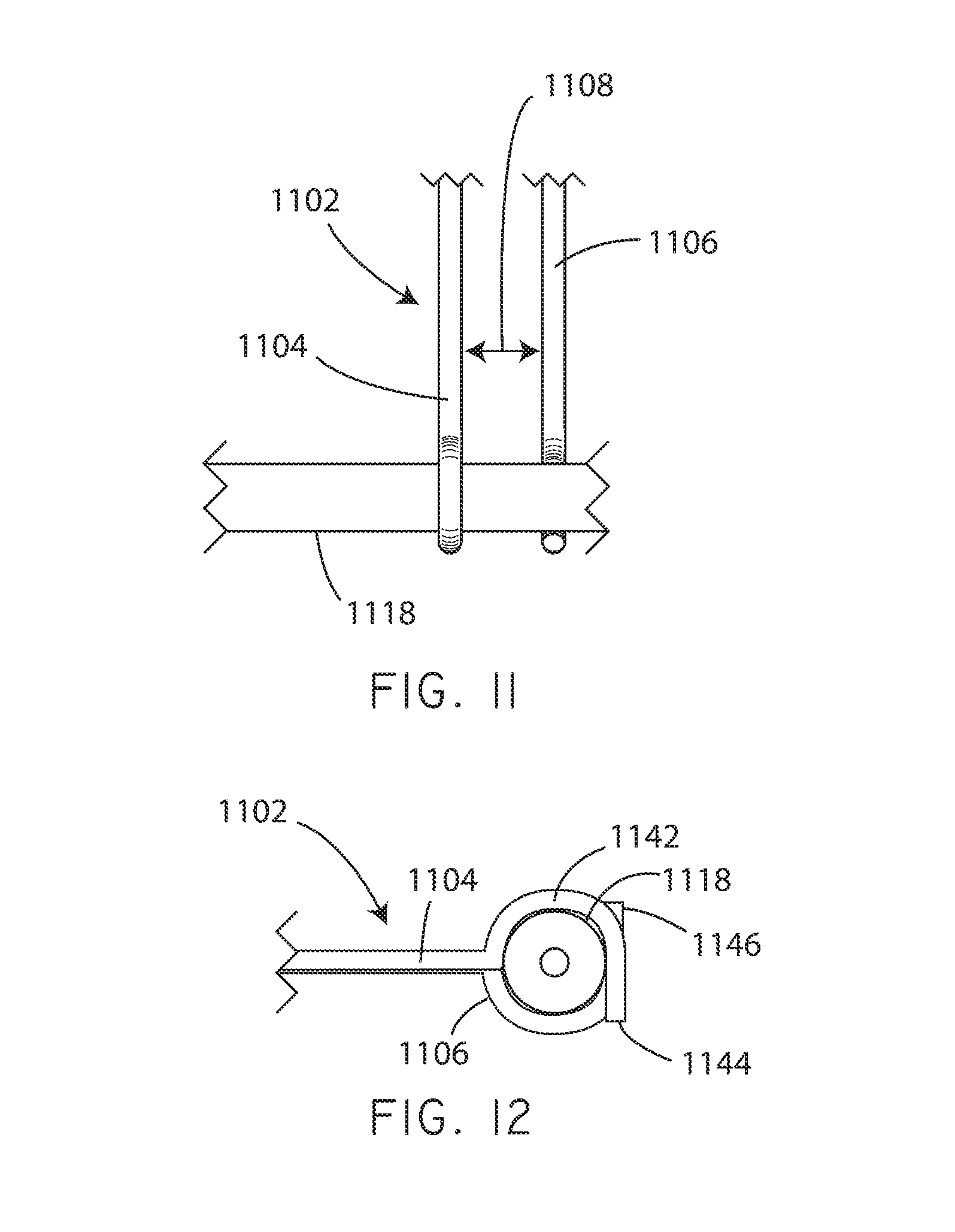
FIG. 11 is a schematic top view of a movement restriction structure in accordance with various embodiments herein.
FIG. 12 is a schematic end view of a movement restriction structure in accordance with various embodiments herein.
FIG. 13 is a schematic front view of a movement restriction structure in accordance with various embodiments herein.
FIG. 14 is a schematic front view of a movement restriction structure in accordance with various embodiments herein.
FIG. 15 is a schematic end view of a movement restriction structure in accordance with various embodiments herein.
FIG. 16 is a schematic end view of a fluid applicator in accordance with various embodiments herein.
FIG. 17 is a schematic perspective view of a coating apparatus in accordance with various embodiments herein.
FIG. 18 is a schematic perspective view of a fluid applicator interfacing with balloon catheter as held by a movement restriction structure.
FIG. 19 is a schematic perspective view of a fluid applicator interfacing with balloon catheter as held by a movement restriction structure.
FIG. 20 is a schematic perspective view of elements of a coating apparatus in accordance with various embodiments herein.
FIG. 21 is a schematic view through the middle of a fluid applicator in accordance with various embodiments herein.
FIG. 22 is a schematic cross-sectional view of a fluid applicator interfacing with balloon catheter as held by a movement restriction structure.
FIG. 22A is a schematic cross-sectional view of a fluid applicator interfacing with balloon catheter as held by a movement restriction structure in accordance with various embodiments.
FIG. 23 is a schematic cross-sectional view of a fluid applicator interfacing with a balloon catheter in accordance with various embodiments
FIG. 24 is a schematic top view of a fluid applicator interfacing with a balloon catheter in accordance with various embodiments.
FIG. 25 is a schematic top view of a fluid applicator interfacing with a balloon catheter in accordance with various embodiments.
FIG. 26 is a schematic top view of a fluid applicator interfacing with a balloon catheter in accordance with various embodiments.
FIG. 27 is a schematic top view of a fluid applicator interfacing with a balloon catheter in accordance with various embodiments.
FIG. 28 is a schematic top view of a fluid applicator interfacing with a balloon catheter in accordance with various embodiments.
FIG. 29 is a schematic cross-sectional view of a fluid applicator.
FIG. 30 is a schematic view of a fluid applicator interfacing with a surface of a device to be coated.
FIG. 31 is a schematic top view of a fluid applicator interfacing with a surface of a device to be coated.
FIG. 32 is a schematic top view of a fluid applicator interfacing with a surface of a device to be coated.
FIG. 33 is a schematic top view of a fluid applicator interfacing with a surface of a device to be coated.
FIG. 34 is a schematic view of a portion of a medical device in accordance with various embodiments herein.
FIG. 35 is a schematic view of a medical device in accordance with various embodiments herein.
While the invention is susceptible to various modifications and alternative forms, specifics thereof have been shown by way of example and drawings, and will be described in detail. It should be understood, however, that the invention is not limited to the particular embodiments described. On the contrary, the intention is to cover modifications, equivalents, and alternatives falling within the spirit and scope of the invention.
DETAILED DESCRIPTION OF THE INVENTION
The embodiments of the present invention described herein are not intended to be exhaustive or to limit the invention to the precise forms disclosed in the following detailed description. Rather, the embodiments are chosen and described so that others skilled in the art can appreciate and understand the principles and practices of the present invention.
All publications and patents mentioned herein are hereby incorporated by reference. The publications and patents disclosed herein are provided solely for their disclosure. Nothing herein is to be construed as an admission that the inventors are not entitled to antedate any publication and/or patent, including any publication and/or patent cited herein.
Embodiments herein can be used to apply visually uniform coatings, such as coatings including active agents, onto medical devices, such as onto the balloons of drug coated or drug eluting balloon catheters, that have substantially uniform active agent concentrations along the length of the medical device. For example, in some embodiments, coatings can be formed with apparatus and methods wherein each section of the device that has been coated contains an amount of the active agent that is within ten percent of the average amount of active agent across all sections coated.
Referring now to FIG. 1, a schematic side view is shown of a coating apparatus 100 in accordance with various embodiments herein. The coating apparatus 100 is shown in conjunction with a drug coated balloon catheter 102. The drug coated balloon catheter 102 can include a catheter shaft 104 and a balloon 106. The balloon 106 can assume a deflated configuration and an inflated configuration. The drug coated balloon catheter 102 can include a distal end 103 and a proximal end 105. The drug coated balloon catheter 102 can include a proximal end manifold (not shown). The coating apparatus 100 can include a coating application unit 108. The coating apparatus 100 can further include, in some embodiments, an axial motion mechanism 110 (axial with respect to the axis of rotation of the balloon catheter and thus parallel to the lengthwise axis of the balloon catheter) that can function to move one or more components of the coating application unit 108. In some embodiments, axial motion can be substantially horizontal. In other embodiments, axial motion can be substantially vertical. In some embodiments, axial motion can be somewhere in between horizontal and vertical, depending on the orientation of the lengthwise axis of the balloon catheter. However, it will be appreciated that in other embodiments, the coating application unit 108 can remain stationary.
Coating of the balloon 106 to make it drug coated can occur starting at the proximal end of the balloon and proceeding to the distal end. However, in other embodiments, coating of the drug coated balloon 106 can occur starting at the distal end of the balloon and proceeding to the proximal end. In many embodiments, coating can take place with a single pass of the coating application unit 108 with respect to the balloon. However, in other embodiments, multiple passes of the coating application unit with respect to the balloon can be made.
The coating apparatus 100 can further include a fluid pump 112. The fluid pump 112 can be, for example, a syringe pump. The fluid pump 112 can be in fluid communication with components of the coating application unit 108 (such as the fluid applicator) and with a fluid reservoir 114. The fluid pump 112 can operate to pump a coating solution at a rate sufficient to apply about 0.5 .mu.l to about 10 .mu.l of the coating solution per millimeter of length of the balloon or other device to be coated. The coating apparatus 100 can further include a rotation mechanism 116 (or rotating balloon catheter fixture). The rotation mechanism 116 can be directly or indirectly coupled to the drug coated balloon catheter in order to rotate the drug coated balloon catheter 102 around its lengthwise (major) axis (about the central lumen of the catheter). In some embodiments, the drug coated balloon catheter can be rotated at a speed of between 100 and 400 rotations per minute. In some embodiments, the drug coated balloon catheter can be rotated at a speed of between 200 and 300 rotations per minute.
In some embodiments, a guide wire 107, passing through the central lumen of the catheter, can extend from the distal tip of the catheter and be inserted into a distal tip support ring 109 or guide. In this manner, the guide wire 107 can be used to support the distal tip of the balloon catheter to be coated while allowing the balloon catheter to rotate freely.
The coating apparatus 100 can further include, in some embodiments, an axial motion mechanism 118 which can be configured to move the drug coated balloon catheter 102 in the direction of its lengthwise major axis. In some embodiments, axial motion can be substantially horizontal. In other embodiments, axial motion can be substantially vertical. In some embodiments, axial motion can be somewhere in between horizontal and vertical, depending on the orientation of the lengthwise axis of the balloon catheter. In some embodiments, the axial motion mechanism 118 can be a linear actuator. In some embodiments, the axial motion mechanism 118 can include an electric motor. The coating apparatus 100 can further include a frame member 120 (in some embodiments this can also be referred to as an axial motion support rail). The frame member 120 can support other components of the coating apparatus 100 such as one or more guides 126. The frame member 120 can itself be support by a platform 122. The coating apparatus 100 can further include a controller 124 that can serve to control operation of the coating apparatus 100 including, specifically, fluid pump 112, axial motion mechanism 110, rotation mechanism 116, and axial motion mechanism 118.
Referring now to FIG. 2, a schematic view of a coating application unit 108 in accordance with various embodiments herein is shown. The coating application unit 108 can include a movement restriction structure 202 (or wobble control structure), an air nozzle 204, a fluid distribution bar 206, and a fluid applicator 208. The movement restriction structure 202 can serve to limit the lateral motion (e.g., movement in a direction perpendicular to the lengthwise axis of the catheter) of the balloon during a coating operation.
The fluid applicator 208 can serve to apply a coating solution 209 to the surface of the balloon 212 on the drug coated balloon catheter. In some embodiments, the fluid applicator 208 is less than or equal to about 1 cm away from the movement restriction structure 202. In some embodiments, the air nozzle 204 is less than or equal to about 2 cm away from the fluid applicator 208. The air nozzle 204 can provide a stream of a gas in order to assist in drying the coating solution after it has been applied to the balloon or other medical device.
The fluid distribution bar 206 can serve to promote distribution of the applied coating solution. For example, the fluid distribution bar 206 can serve to prevent pooling of the applied coating solution. In some embodiments, the fluid distribution bar 206 can be at least about 0.5 mm away from the fluid applicator and less than 2 cm away. In some embodiments, the fluid distribution bar 206 can be at least about 0.2 cm away from the fluid applicator and less than 2 cm away.
In this embodiment, the coating application unit 108 can move, relative to the balloon 212 in the direction of arrow 230. As such, during a coating operation, the movement restriction structure 202 can pass over the balloon first, followed by the fluid applicator 208, followed by the fluid distribution bar 206, with the air nozzle last. It should be emphasized, however, that this movement is relative in the sense that in some embodiments the coating application unit 108 is moving and the balloon 212 is rotating but otherwise stationary, in some embodiments the balloon 212 is rotating and moving in the direction of its lengthwise axis and the coating application unit 108 is stationary, in still other embodiments both the coating application unit 108 and the balloon 212 are moving. The speed of movement of the balloon 212 relative to the coating application unit 108 can vary depending on the amount of coating solution to be applied. In some embodiments the speed can be from about 0.02 centimeters per second to about 0.2 centimeters per second.
It will be appreciated that based on the rotation of the drug coated balloon catheter and the movement of the balloon relative to the coating application unit that the path of the deposition of the coating onto the balloon follows a roughly helical path. It will be appreciated that the combination of the rotation speed of the drug coated balloon catheter and the speed of the movement of the balloon relative to the coating application unit can influence the amount of coating solution that is deposited at any given point and the nature of the helical path. For example, the coating material can be deposited in helical layers that partially overlap one another at their edges, helical layers wherein the edge of one turn substantially meets the edge of a previous turn, and helical layers wherein there are gaps in between subsequent helical turns. In some embodiments, these helical patterns can be configured so as to maximize release of the active agent. For example, in some embodiments, the apparatus can be used to coat device so as to produce helical ridges of the coating material on the balloon surface.
In some embodiments, the coating application unit 108 can optionally include a manifold block 210. The manifold block 210 can facilitate support of, and in some embodiments movement of, the components of the coating application unit 108. In some embodiments, the components of the coating application unit can move together as a unit during a coating operation. However, in other embodiments the components of the coating application unit are substantially separate from one another and can move independently. In some embodiments, the components of the coating application unit are all substantially stationary during a coating operation.
While the components of the coating application unit 108 are shown in FIG. 2 as being within a particular plane and disposed at approximately the same angle with respect to the balloon 212 being coated, it will be appreciated that this is not the case with all embodiments herein. In some embodiments, the components of the coating application unit 108 lie in different planes with respect to the balloon 212 and/or the components of the coating application unit 108 are disposed at different angles (both with respect to the lengthwise axis of the balloon and radially) with respect to the balloon.
Referring now to FIG. 3, a schematic end view is shown of a movement restriction structure 302 in accordance with various embodiments herein. The structure 302 can include a body member 306 defining a channel 304 or aperture. The body member 306 can be formed of various materials such as polymers, metals, ceramics, and the like. In a particular embodiment, the body member 306 is formed of polytetrafluoroethylene (PTFE). The channel 304 can have a diameter 308 that is sufficiently large so as to accommodate the balloon of a drug coated balloon catheter in an expanded state. In the example of FIG. 3, the channel 304 is shown as being bounded in a radially continuous manner by the body member 306 (e.g., it is completely surrounded on all sides by the body member 306). However, it will be appreciated that in some embodiments the channel 304 is not bounded in a radially continuous manner by the body member 306.
In some embodiments the movement restriction structure can include multiple pieces that together define a channel or aperture. Referring now to FIG. 4, a movement restriction structure 402 is shown including a body member that includes a first piece 406 and a second piece 408 that together define a channel 404 or aperture. The first piece 406 and second piece 408 are joined together by a hinge 410 in this embodiment, however it will be appreciated that there are many ways known to those of skill in the art by which to hold two structure pieces in association with one another.
It will be appreciated that body members of movement restriction structures can take on many different shapes. In addition, the shape of the channel defined by the body member(s) can take on many different shapes. Referring now to FIG. 5, a movement restriction structure 502 is shown including a first side piece 506 and a second side piece 508 that together define a channel 504 or aperture. In this case, the first side piece 506 and the second side piece 508 are supported by a frame member 510. However, it will be appreciated that there are many different ways of supporting the first side piece 506 and the second side piece 508. In some embodiments, one or both of the first side piece 506 and the second side piece 508 can be spring loaded such that it is biased toward sliding inward toward the other piece. In other embodiments, one or both of the first side piece 506 and the second side piece 508 can be adjustable and then fixed in position so as to create a channel 504 of a desired size.
Referring now to FIG. 6 a schematic end view of a fluid distribution bar 606 in conjunction with the balloon 618 of a drug coated balloon catheter 614 is shown. In some embodiments, the fluid distribution bar 606 can include a support structure 608 and a shaft 610. In some embodiments, the support structure 608 can be omitted. The shaft 610 can be formed of various materials such as polymers, metals, ceramics, and the like. In a particular embodiment, the shaft 610 is formed of polytetrafluoroethylene (PTFE). The shaft 610 can be of various lengths and diameters and can have various cross-sectional shapes. In some embodiments, the shaft 610 is from about 2 mm to about 15 cm and is substantially circular in cross-sectional shape. In some embodiments, the shaft is about 1/16 inch in diameter. The shaft 610 is configured to rest against the balloon 618 of the balloon catheter 614.
In yet other embodiments the fluid distribution bar 606 can include multiple rods or extensions from support structure 608. Exemplary of these embodiments can include, but are not limited to, a comb-like structure or a brush.
The balloon 618 is supported by the catheter shaft 616, but generally only at the ends of the balloon 618. Because of the limited support of the balloon 618 by the catheter shaft 616, the inherent flexibility of the balloon material and manufacturing variations, the balloon 618 may not be perfectly round. As such, when it is being rotated during a coating operation there may be variations in the distance of the outer surface of the balloon 618 from the catheter shaft 616 of the balloon catheter 614. If unaccounted for, this could lead to circumstances where the fluid distribution bar 606 does not maintain contact with the surface of the balloon 618. As such, the shaft 610 of the fluid distribution bar 606 can be configured to maintain contact with the surface of the balloon 618. For example, the shaft 610 of the fluid distribution bar 606 can be positioned such that it exerts a small degree of pressure against the surface of the balloon 618 such that when an irregularity in the balloon is encountered the fluid distribution bar 606 can move slightly in order to maintain contact with the balloon surface. In some embodiments the shaft 610 of the fluid distribution bar 606 is flexible to accommodate movement to stay in contact with the balloon surface. In other embodiments, the fluid distribution bar 606 can be configured to pivot from where it is mounted in order to accommodate movement to stay in contact with the balloon surface.
While the shaft 610 of the fluid distribution bar 606 is shown in FIG. 6 as contacting the top of the balloon 618 and thus exerting a pressure downward in the direction of arrow 612, it will be appreciated that in other embodiments the surface of the balloon 618 can be contacted at other points along its surface, such as on the sides or on the bottom.
Referring now to FIG. 7, a schematic end view of a fluid applicator 708 in conjunction with the balloon 718 of a drug coated balloon catheter 714 is shown in accordance with an embodiment of the invention. The fluid applicator 708 can include a shaft 706 and an orifice 704. In some embodiments, the fluid applicator 708 can be a pipette. Fluid, such as a coating solution, can travel through the shaft 706 of the fluid applicator 708 in order to be deposited on the surface of the balloon 718 of the drug coated balloon catheter 714. The shaft 706 is configured to rest against the balloon 718 of the balloon catheter 714. The balloon 718 is supported by the catheter shaft 716, but generally only at the ends of the balloon 718. Because of the limited support of the balloon 718 by the catheter shaft 716, the inherent flexibility of the balloon material and manufacturing variations, the balloon 718 may not be perfectly round. As such, when it is being rotated during a coating operation there may be variations in the distance of the outer surface of the balloon 718 from the catheter shaft 716 of the balloon catheter 714. If unaccounted for, this could lead to circumstances where the fluid applicator 708 does not maintain contact with the surface of the balloon 718. As such, the shaft 706 of the fluid applicator 708 can be configured to maintain contact with the surface of the balloon 718. For example, the shaft 706 of the fluid applicator 708 can be positioned such that it exerts a small degree of pressure against the surface of the balloon 718 such that when an irregularity in the balloon 718 is encountered the fluid applicator 708 can move slightly in order to maintain contact with the balloon surface. In some embodiments the shaft 706 of the fluid applicator 708 is flexible to accommodate movement to stay in contact with the balloon surface. In other embodiments, the fluid applicator 708 can be configured to pivot from where it is mounted in order to accommodate movement to stay in contact with the balloon surface. In other embodiments, the fluid applicator may not be in direct contact with the balloon surface but situated closely, for example within 1 millimeter.
While the shaft 706 of the fluid applicator 708 is shown in FIG. 7 as contacting the upper right side (approximately equivalent to an area between the 1 and 2 position of a clock face) of the balloon 718, it will be appreciated that in other embodiments the surface of the balloon 718 can be contacted at other points along its surface. For example, in some embodiments, the very top of the balloon 718 can be contacted by the fluid applicator 708.
In some embodiments the fluid distribution bar 606 and the fluid applicator 708 can be configured such that the shaft 610 of the fluid distribution bar 606 contacts the surface of the balloon at approximately the same point radially along the surface of the balloon as the shaft 706 of the fluid applicator 708. In some embodiments, the fluid distribution bar 606 and the fluid applicator 708 can be configured such that the shaft 610 of the fluid distribution bar 606 contacts the surface of the balloon within at least 90 degrees radially along the surface of the balloon as the shaft 706 of the fluid applicator 708.
Referring now to FIG. 8, a schematic end view of an air nozzle 804 in conjunction with the balloon 818 of a drug coated balloon catheter 814 is shown. The air nozzle 804 can include an orifice 806. A gas such nitrogen, ambient air or another gas can be directed to flow out of the orifice 806 and towards the balloon 818 of the drug coated balloon catheter 814. In some embodiments, the gas can be heated. For example, in some embodiments the gas can be from about 50 to about 70 degrees Celsius. While the orifice 806 of the air nozzle 804 is shown in FIG. 8 as directing air to the top of the balloon 818, it will be appreciated that in other embodiments the air nozzle 804 and orifice 806 can be configured to direct air at other parts of the balloon 818 such as, but not limited to, the sides or the bottom.
Referring now to FIG. 9, a schematic view of a coating application unit in accordance with various embodiments herein is shown. The coating application unit 900 can include a movement restriction structure 902, a first air nozzle 914, a fluid applicator 908, and a second air nozzle 904. The first air nozzle 914 is disposed on one side of the fluid applicator 908 and the second air nozzle 904 is disposed on the other side of the fluid applicator 908. In some embodiments the first air nozzle 914 can act to avoid pooling of the coating at the fluid applicator 908. In some embodiments the second air nozzle 904 can act to avoid pooling of the coating fluid at the fluid applicator 908. The fluid applicator 908 can serve to apply a coating solution 909 to the surface of the balloon on the drug coated balloon catheter. Other embodiments can include three or more air nozzles.
In this embodiment, the coating application unit 900 can move, relative to the balloon 912 in the direction of arrow 930. As such, during a coating operation, the movement restriction structure 902 can pass over the balloon first. It should be emphasized, however, that this movement is relative in the sense that in some embodiments the coating application unit 900 is moving and the balloon 912 is rotating but otherwise stationary, in some embodiments the balloon 912 is rotating and moving in the direction of its lengthwise axis and the coating application unit 900 is stationary, in still other embodiments both the coating application unit 900 and the balloon 912 are moving.
It will be appreciated that the coating solution can be applied on to the balloon in various ways including, but not limited to, spraying (including both ultrasonic spraying and conventional spraying techniques), dribbling, blade coating, contact printing, drop coating, or the like. In some embodiments, the fluid applicator can include a fluid spray nozzle. Referring now to FIG. 10, a schematic view of a coating application unit in accordance with various embodiments herein is shown. The coating application unit 1000 can include a movement restriction structure 1002, an air nozzle 1004, a fluid distribution bar 1006, and a fluid spray nozzle 1008. The fluid spray nozzle 1008 can serve to apply a coating solution 1009 to the surface of the balloon 1012 on the drug coated balloon catheter. In some embodiments there is a small gap between the fluid spray nozzle 1008 and the balloon 1012. For example, the gap can be between 1 millimeter and 10 centimeters. In some embodiments, multiple fluid applicators and/or spray nozzles can be used.
In this embodiment, the coating application unit 1000 can move, relative to the balloon 1012 in the direction of arrow 1030. As such, during a coating operation, the movement restriction structure 1002 can pass over the balloon first. It should be emphasized, however, that this movement is relative in the sense that in some embodiments the coating application unit 1000 is moving and the balloon 1012 is rotating but otherwise stationary, in some embodiments the balloon 1012 is rotating and moving in the direction of its lengthwise axis and the coating application unit 1000 is stationary, in still other embodiments both the coating application unit 1000 and the balloon 1012 are moving.
FIG. 11 is a schematic top view of a movement restriction structure in accordance with various embodiments herein. The structure 1102 can include a first body member 1104 and a second body member 1106. The first and second body members 1104, 1106 can be formed of various materials such as polymers, metals, ceramics, and the like. The first and second body members 1104, 1106 can function together to restrict movement of a balloon 1118 to be coated. The first and second body members 1104, 1106 can be separated from one another by a distance 1108 that is greater than or equal to the diameter of the balloon 1118. In some embodiments, the distance 1108 is approximately equal to the balloon 1118. In some embodiments, the distance 1108 is between about 3 millimeters and about 10 millimeters.
FIG. 12 is a schematic end view of the movement restriction structure 1102. The first body member 1104 can include a curved segment 1142 and an end 1144. The curved segment 1142 can define a portion of a channel which can surround at least a portion of the balloon 1118, thereby restricting its movement. In some embodiments, the second body member 1106 can be formed similarly but with a different orientation so that together the first body member 1104 and the second body member 1106 can effectively restrict movement of the balloon 1118. For example, the end 1146 of the second body member 1106 can be pointed upward instead of downward. FIG. 13 is a schematic front view of the movement restriction structure 1102 that shows the differing orientations of the first body member 1104 and the second body member 1106.
It will be appreciated that the balloon can be loaded into the movement restriction structure in various ways. For example, in some embodiments, the balloon catheter can simply be threaded through the movement restriction structure before or after being connected with other portions of the apparatus in preparation for coating. In other embodiments, the movement restriction structure itself can be manipulated in order to load the balloon. For example, in some embodiments, the movement restriction structure can be rotated into an open orientation in order to accommodate loading the balloon from the side. Then, in some embodiments, the movement restriction structure can be rotated from the open orientation to a closed orientation in order to lock the balloon in place. Referring now to FIG. 14, a schematic front view of the movement restriction structure 1102 is shown illustrating an open orientation. In this view, it can be seen that the first body member 1104 and the second body member 1106 are rotated approximately 90 degrees from their respective positions in FIG. 13. The balloon 1118 can be slid out from between the first and second body members 1104, 1106 when the movement restriction structure 1102 is in this orientation. In operation, then, a new balloon to be coated can be slid back in between the first and second body members 1104, 1106 and then the body members can be rotated in the direction of arrows 1150 and 1152 to put the movement restriction structure 1102 into the closed position (illustrated in FIG. 13) where the balloon 1118 is locked in place. In some embodiments, the first and second body members 1104, 1106 can be rotated in either direction. The first and second body members 1104, 1106 can be rotated together around a single axis or independently from one another around two separate axes.
It will be appreciated that body members of movement restrictions structures in accordance with embodiments herein can also include various other features. Referring now to FIG. 15, a schematic end view of portions of a movement restriction structure 1500 are shown in accordance with various embodiments herein. The movement restriction structure 1500 can include a first body member 1502. The first body member 1502 can include a curved segment 1504 and an end 1508. The curved segment 1504 can define a portion of a channel which can surround at least a portion of the balloon 1518, thereby restricting the balloon's 1518 movement, in conjunction with a second body member (not shown in this view). The first body member 1502 can also include an alignment lip 1506 adjacent to the end 1508. The alignment lip 1506 can include a surface 1510 that is angled away from the channel defined by the curved segment 1504. The alignment lip 1506 can aid in positioning the balloon 1518 within the channel formed by the curved segment 1504. For example, when the first body member 1502 is rotated starting from the open position, if the balloon 1518 is slightly out of position by being too close to the end 1508, the surface 1510 of the alignment lip 1506 will contact the balloon 1518 surface and cause the balloon 1518 to move into alignment with the channel.
It will be appreciated that fluid applicators can take on various configurations in accordance with embodiments herein. FIG. 16 is a schematic end view of a fluid applicator 1600 in accordance with various embodiments herein. The fluid applicator 1600 can include a shaft 1602 and an orifice 1608. The orifice 1608 can be located along the shaft 1602 at a position other than at the distal end 1620 of the shaft 1602. Fluid 1604, such as a coating solution, can pass from the fluid applicator 1600 through the orifice 1608 in order to be deposited on the surface of the balloon. The segment 1606 of the shaft 1602 that extends beyond where the orifice 1608 is located can be curved, in some embodiments, in order to form part of a channel which can serve to maintain the position of the balloon relative to the fluid applicator 1600. In some embodiments, segment 1606 can be disposed between the orifice 1608 and the distal end 1620 of the shaft 1602.
Referring now to FIG. 17, a schematic perspective view of a coating apparatus 1700 is shown in accordance with various embodiments herein. The coating apparatus 1700 can include a fluid applicator 1702 and a movement restriction structure 1710. The movement restriction structure 1710 can include an engagement surface 1712 having a U-shaped contour. A device to be coated, such as a balloon catheter 1720, is shown as ready for insertion into the movement restriction structure 1710.
Referring now to FIG. 18, a schematic perspective view is shown of a fluid applicator 1702 interfacing with balloon catheter 1720 as held by a movement restriction structure 1710. The movement restriction structure 1710 can include an engagement surface 1712 having a U-shaped contour. The fluid applicator 1702 can include a contact surface 1708 that is angled with respect to the lengthwise axis of the fluid applicator 1702. The contact surface 1708 can fit against the balloon catheter during the coating operation so as to make contact and aid in holding the balloon catheter against the engagement surface 1712 of the movement restriction structure. 19 is a schematic perspective view of a fluid applicator 1702 interfacing with balloon catheter 1720 as held by a movement restriction structure 1710. A fluid coating composition 1722 is applied onto the surface of the balloon catheter 1720. The fluid coating composition 1722 then passes past a drying nozzle 1726 forming a dried coating 1724.
Referring now to FIG. 20, a schematic perspective view of elements of a coating apparatus in accordance with various embodiments herein. In this view, a coating operation has been completed and the now coated balloon catheter 1720 has been removed from contact with the fluid applicator 1702 and has been moved out from within the engagement surface 1712 of the movement restriction structure 1710.
Referring now to FIG. 21, a schematic cross-sectional view through the middle of a fluid applicator 1702 is shown in accordance with various embodiments herein. The fluid applicator 1702 can be formed of various materials including polymers, metals, ceramics, glasses, and the like. The fluid applicator 1702 can define a central channel 1706 through which a fluid coating composition can be delivered. The fluid applicator 1702 can further include a contact surface 1708. The contact surface 1708 can be angled with respect to the lengthwise axis of the fluid applicator 1702. In some embodiments, the contact surface 1708 can be angled from about 20 degrees to about 70 degrees with respect to the lengthwise axis of the fluid applicator 1702. In some embodiments, the contact surface 1708 is angled such that its surface is substantially parallel with a line that is a tangent to the balloon catheter 1720 at the point of contact between the fluid applicator 1702 and the balloon catheter 1720. A fluid orifice 1704 can be disposed as the distal end of the fluid applicator 1702.
FIG. 22 is a schematic cross-sectional view of a fluid applicator 1702 interfacing with a balloon catheter 1720 as held by a movement restriction structure 1710. The contact surface 1708 of the fluid applicator 1702 can contact the surface of the balloon catheter 1720. In some embodiments, the contact point between the fluid applicator 1702 and the surface of the balloon catheter 1720 can be at a position equivalent to between 9 and 12 on the face of a standard clock (or between 12 and 3 if the fluid applicator 1702 is arranged on the other side of the balloon catheter). If the position of 3 on a clock face is taken as 0 degrees, then the contact point can be between 180 degrees and 270 degrees (or between 270 degrees and 360 degrees if the fluid applicator 1702 is arranged on the other side of the balloon catheter). The surface of the balloon catheter 1720 can contact the engagement surface 1712 of the movement restriction structure 1710. In some embodiments, the leading and trailing edges of the engagement surface 1712 can include curved edges. In some embodiments, the engagement surface 1712 can include a radius of curvature extending from the leading edge to the trailing edge such that the point of contact with the surface of the balloon catheter is in the middle of the engagement surface between the leading edge and the trailing edge.
FIG. 22A is a schematic cross-sectional view of a fluid applicator 1702 interfacing with a balloon catheter 1720 as held by a movement restriction structure 1710. The contact surface 1708 of the fluid applicator 1702 can contact the surface of the balloon catheter 1720. In some embodiments, the contact point between the fluid applicator 1702 and the surface of the balloon catheter 1720 can be at a position equivalent to between 9 and 12 on the face of a standard clock (or between 12 and 3 if the fluid applicator 1702 is arranged on the other side of the balloon catheter). If the position of 3 on a clock face is taken as 0 degrees, then the contact point can be between 180 degrees and 270 degrees (or between 270 degrees and 360 degrees if the fluid applicator 1702 is arranged on the other side of the balloon catheter). Additionally, the fluid applicator 1702 can be held at an angle .theta..sub.2 (with respect to a fully horizontal position) from the contact points described above. The angle .theta..sub.2 can vary between 0 (as shown in FIG. 22A) and as much as 30 degrees. The surface of the balloon catheter 1720 can contact the engagement surface 1712 of the movement restriction structure 1710. In some embodiments, the leading and trailing edges (e.g., oriented such that a line connecting the leading and trailing edges would be perpendicular to the cross-section of FIG. 22A and thus go into and out of the page) of the engagement surface 1712 can include curved edges. In yet other embodiments the engagement surface can include an engagement ramp 1711 to allow the balloon catheter 1720 to more easily become engaged with the engagement surface 1712. In some embodiments, the engagement surface 1712 can include a radius of curvature extending from the leading edge to the trailing edge such that the point of contact with the surface of the balloon catheter is in the middle of the engagement surface between the leading edge and the trailing edge.
In some embodiments the fluid distribution bar 2306 can act to further restrict movement and keep the balloon catheter 1720 engaged against the engagement surface 1712. In some exemplary embodiments, wherein the angle .theta..sub.2 exceeds 15 degrees, the fluid distribution bar 2306 can further restrict movement and keep the balloon catheter 1720 engaged against the engagement surface 1712.
Referring now to FIG. 23, a schematic cross-sectional view is shown of a fluid applicator 2308 interfacing with the surface 2320 of a balloon catheter. The coating apparatus can further include a fluid distribution bar 2306 (or wire) that is connected to the fluid applicator 2308 and is arranged to contact the surface 2320 of the balloon catheter.
In this view, the fluid distribution bar 2306 is angled upward with respect to device to be coated such that it contacts the device to be coated at a higher point than the fluid applicator. In some embodiments, the fluid distribution bar is arranged such that it does not actually contact the surface of the device to be coated but is sufficiently close so as to contact any coating material that is deposited thereon. The angle (.theta..sub.1) of the body of the fluid distribution bar 2306 with respect to the lengthwise major axis of the fluid applicator 2308 and/or the tip of the fluid applicator 2308 can be from about 0 degrees to about 20 degrees. In some embodiments the angle (.theta..sub.1) is from about 0.5 degrees to about 20 degrees. In some embodiments, the angle is sufficient such that the body of the fluid distribution bar 2306 is tangent with respect to the surface of the device to be coated. In other embodiments, the fluid distribution bar is not be angled upward.
In this view, the fluid distribution bar 2306 is shown connected to the top side of the fluid applicator 2308. However, it will be appreciated that the fluid distribution bar 2306 can also be connected to the sides, bottom, or any other portion of the fluid applicator in other embodiments. In still other embodiments, the fluid distribution bar is not connected to the fluid applicator at all. FIG. 24 is a schematic top view of the fluid applicator 2308 and fluid distribution bar 2306 interfacing with the surface 2320 balloon catheter.
While the embodiment shown in 24 illustrates an embodiment of a fluid distribution bar 2306 that is substantially straight, it will be appreciated that in other embodiments the fluid distribution bar can be curved and/or have bent portions. In FIG. 25 a schematic top view of a fluid applicator interfacing with a balloon catheter is shown in accordance with another embodiment. The coating apparatus includes a fluid distribution bar 2306 that is connected to the fluid applicator 2308 and is arranged to contact the surface 2320 of the balloon catheter. The fluid distribution bar 2306 also includes a portion 2316 (or tail) that is angled with respect to the major axis of the fluid applicator. The portion 2316 extends in a direction that is downstream of the fluid applicator (e.g. on the side of the fluid applicator where coating material has already been deposited based on how the fluid applicator and/or the device to be coated move with respect to one another). However, in other embodiments, the portion 2316 could extend upstream of the fluid applicator.
In some embodiments the portion 2316 can be substantially parallel with the lengthwise axis of the device to be coated, such as the balloon catheter. In other embodiments, the portion 2316 can be angled with respect to the lengthwise axis of the device to be coated. In FIG. 26 a schematic top view is shown of a fluid applicator interfacing with a balloon catheter in accordance with various embodiments. The coating apparatus includes a fluid distribution bar 2306 that is connected to the fluid applicator 2308 and is arranged to contact the surface 2320 of the balloon catheter. The fluid distribution bar 2306 includes a portion 2316 that is angled back toward the fluid applicator 2308. FIG. 27 shows another embodiment of the coating apparatus. In this view, the fluid distribution bar 2306 includes a portion 2316 that is angled away from the fluid applicator 2308.
FIG. 28 is a schematic top view of a fluid applicator interfacing with a balloon catheter in accordance with another embodiment. The coating apparatus includes a fluid distribution bar 2306 that is connected to the fluid applicator 2308 and is arranged to contact the surface 2320 of the balloon catheter. The fluid distribution bar 2306 includes a portion 2318 that is disposed upstream of the fluid applicator and a portion 2316 that is disposed downstream of the fluid applicator.
It will be appreciated that the fluid distribution bar can be made of various materials. In some embodiments it can be formed of polymers, metals, composites, ceramics and the like. In some embodiments it is flexible. In other embodiments it is substantially rigid. In some embodiments it can have a diameter that is less than the diameter of the fluid applicator. In some embodiments it is circular in cross sectional. In other embodiments it can be polygonal, ovoid, or irregular in cross-section. In some embodiments it can have a flattened surface where it contacts the device to be coated.
It will be appreciated that coating solutions applied onto balloons can include various components including, but not limited to, one or more active agents, carrier agents and/or solvents, polymers (including degradable or non-degradable polymers), excipients, and the like. The relative amounts of the components of the coating solution will depend on various factors including the desired amount of active agent to be applied to the balloon and the desired release rate of the active agent.
Embodiments herein include methods of applying coatings onto balloon catheters. In an embodiment, the method can include rotating a balloon catheter with a rotation mechanism, the balloon catheter comprising a balloon, contacting the balloon with a movement restriction structure defining a channel, wherein the channel limits lateral movement of the balloon, applying a coating solution onto the surface of the balloon with a fluid applicator (such as through direct contact with a fluid applicator), contacting the surface of the balloon with a fluid distribution bar, and blowing a stream of a gas onto the surface of the balloon. In some embodiments, the balloon catheter can be rotated at a speed of between 100 and 400 rotations per minute.
In some embodiments, the method can include moving the fluid applicator relative to the lengthwise axis of the drug eluting balloon catheter. In some embodiments, the method can include moving the drug eluting balloon catheter along its lengthwise axis relative to the fluid applicator, fluid distribution bar, and movement restriction structure.
In FIG. 29 a schematic cross-sectional view is show of a fluid applicator 2308. The fluid applicator 2308 can include a tip 2902 having a face 2904 (or surface) that is angled with respect to the lengthwise axis of the fluid applicator 2308. The face 2904 can extend all the way across the width of the tip 2902 in some embodiments. In some embodiments, a line that connects the top portion 2903 of the tip 2902 with the bottom portion 2905 of the tip 2902 (or the line is parallel to the face 2904 of the tip 2902) can have an angle .theta..sub.2 with respect to a line parallel to the lengthwise axis of the fluid applicator 2308. In some embodiments, angle .theta..sub.2 can be from about 95 to about 175 degrees. In some embodiments, Angle .theta..sub.2 can be from about 105 to about 165 degrees. In some embodiments, Angle .theta..sub.2 can be from about 115 to about 155 degrees. In some embodiments, Angle .theta..sub.2 can be from about 125 to about 145 degrees. In some embodiments, Angle .theta..sub.2 can be from about 130 to about 140 degrees.
FIG. 30 shows a view of the fluid applicator 2308 interfacing with a surface 3020 of a device to be coated, such as a balloon catheter. The fluid applicator 2308 can be configured to rotate around its lengthwise axis as indicated by arrow 3002. In some embodiments, the fluid applicator 2308 can be connected to a rotation mechanism to cause it to rotate.
Referring now to FIG. 31, a schematic top view is shown of a fluid applicator 2308 interfacing with a surface 3020 of a device to be coated. In this view, the face of the fluid applicator 2308 is oriented downward toward the surface 3020 consistent with the orientation shown in FIG. 30. It has been found that this orientation of the tip face 2904 results in a coating 3104 being applied that is substantially continuous in coverage. In FIG. 32, a schematic top view is shown of a fluid applicator 2308 interfacing with a surface 3020 of a device to be coated wherein the face 2904 of the tip 2902 is oriented differently than as shown in FIG. 31. In this view, the fluid applicator 2308 has been rotated approximately 90 degrees such that the face 2904 of the tip 2902 is now facing approximately sideward with respect to the surface 3020. It has been found that this orientation of the tip face 2904 results in a coating 3104 being applied that is discontinuous in coverage and forms a spiral or helical shape.
The degree of rotation of the fluid applicator 2308 can vary. By way of example, in some embodiments, the fluid applicator 2308 can be rotated from about 10 degrees to about 350 degrees. In some embodiments, the fluid applicator 2308 can be rotated from about 10 degrees to about 170 degrees. In some embodiments, the fluid applicator 2308 can be rotated from about 45 degrees to about 135 degrees. In some embodiments, the fluid applicator 2308 can be rotated from about 60 degrees to about 120 degrees. In some embodiments, the fluid applicator 2308 can be rotated from about 75 degrees to about 105 degrees. In some embodiments, the fluid applicator 2308 can be rotated from about 85 degrees to about 95 degrees. In some embodiments, the fluid applicator 2308 can be rotated about 90 degrees.
In various embodiments, the fluid applicator 2308 can be rotated to a particular orientation in order to create either a continuous or discontinuous coating as desired. In some embodiments, the fluid applicator 2308 can be rotated during a coating application process allowing for the creation of medical devices having segments of continuous coating coverage and segments with discontinuous coating coverage.
Referring now to FIG. 33, a schematic top view is shown of a fluid applicator 2308 interfacing with a surface 3020 of a device to be coated. In this view, the lengthwise axis 3361 of the fluid applicator 2308 forms an angle .theta..sub.3 with respect to the lengthwise axis 3363 of the device to be coated. In specific, angle .theta..sub.3 can be from about 0 to about 180 degrees. In some embodiments, angle .theta..sub.3 can be from about 20 to about 160 degrees. In some embodiments, angle .theta..sub.3 can be from about 45 to about 135 degrees. In some embodiments, angle .theta..sub.3 can be from about 70 to about 110 degrees. In some embodiments, angle .theta..sub.3 can be from about 85 to about 95 degrees. In some embodiments, angle .theta..sub.3 can be about 90 degrees. In some embodiments, angle .theta..sub.3 can be from about 115 degrees to about 155 degrees. In some embodiments, angle .theta..sub.3 can be from about 125 degrees to about 145 degrees.
Referring now to FIG. 34, a schematic view is show of a portion of a medical device 3400 having a surface 3402. The surface 3402 includes a segment 3406 with continuous coating coverage and segments 3404 with discontinuous coating coverage. The segment with discontinuous coating coverage can have various shaped coating configurations such as spiral, helical, ring, and the like. In some embodiments, the surface 3402 can also include a segment 3408 with no coating coverage.
It will be appreciated that the segments can be aligned with various features of the device to be coated. By way of example, to decrease the amount of coating material in an area near the ends of a balloon on a balloon catheter, the fluid applicator can be rotated during the coating process to produce a discontinuous coating segment when approaching the ends of the balloon.
Referring now to FIG. 35, a schematic view of a medical device 3400 is shown. The medical device 3400 can optionally include a connection manifold 3405, a shaft 3403 having a surface, and an expandable portion 3404 (such as a balloon) having a surface. The expandable portion 3404 can include a proximal end 3410 and a distal end 3412. Coating segments, such as those shown in FIG. 34, can be disposed onto one or more of the shaft 3403 and the expandable portion 3404. In some embodiments, the expandable portion 3404 can include multiple coating segments thereon disposed adjacently to one another. By way of example, the expandable portion 3404 can include both continuous coating coverage segments and discontinuous coating coverage segments.
In some embodiments, the medical device 3400 can include at least one continuous coverage segment and at least two discontinuous coverage segments in some embodiments. In some embodiments, the discontinuous coverage segment can be disposed over at least one of the distal end and the proximal end. In some embodiments, a first discontinuous coverage segment can be disposed over the proximal end and a second discontinuous coverage segment can be disposed over the distal end. In some embodiments, the continuous coverage segment can be disposed over the expandable portion between the distal end and the proximal end.
In various embodiments, a method of coating a medical device is included. The method can include rotating a medical device to be coated with a rotation mechanism. In some embodiments, the medical device can be a balloon catheter comprising a balloon. The method can further include contacting the surface of the medical device with a fluid applicator, applying a coating solution onto the surface of the balloon with the fluid applicator, and rotating the fluid applicator axially about its lengthwise major axis.
It should be noted that, as used in this specification and the appended claims, the singular forms "a," "an," and "the" include plural referents unless the content clearly dictates otherwise. Thus, for example, reference to a composition containing "a compound" includes a mixture of two or more compounds. It should also be noted that the term "or" is generally employed in its sense including "and/or" unless the content clearly dictates otherwise.
It should also be noted that, as used in this specification and the appended claims, the phrase "configured" describes a system, apparatus, or other structure that is constructed or configured to perform a particular task or adopt a particular configuration to. The phrase "configured" can be used interchangeably with other similar phrases such as arranged and configured, constructed and arranged, constructed, manufactured and arranged, and the like.
All publications and patent applications in this specification are indicative of the level of ordinary skill in the art to which this invention pertains. All publications and patent applications are herein incorporated by reference to the same extent as if each individual publication or patent application was specifically and individually indicated by reference.
The invention has been described with reference to various specific and preferred embodiments and techniques. However, it should be understood that many variations and modifications may be made while remaining within the spirit and scope of the invention.
* * * * *
References
D00000
D00001
D00002
D00003
D00004
D00005
D00006
D00007
D00008
D00009
D00010
D00011
D00012

D00013

D00014
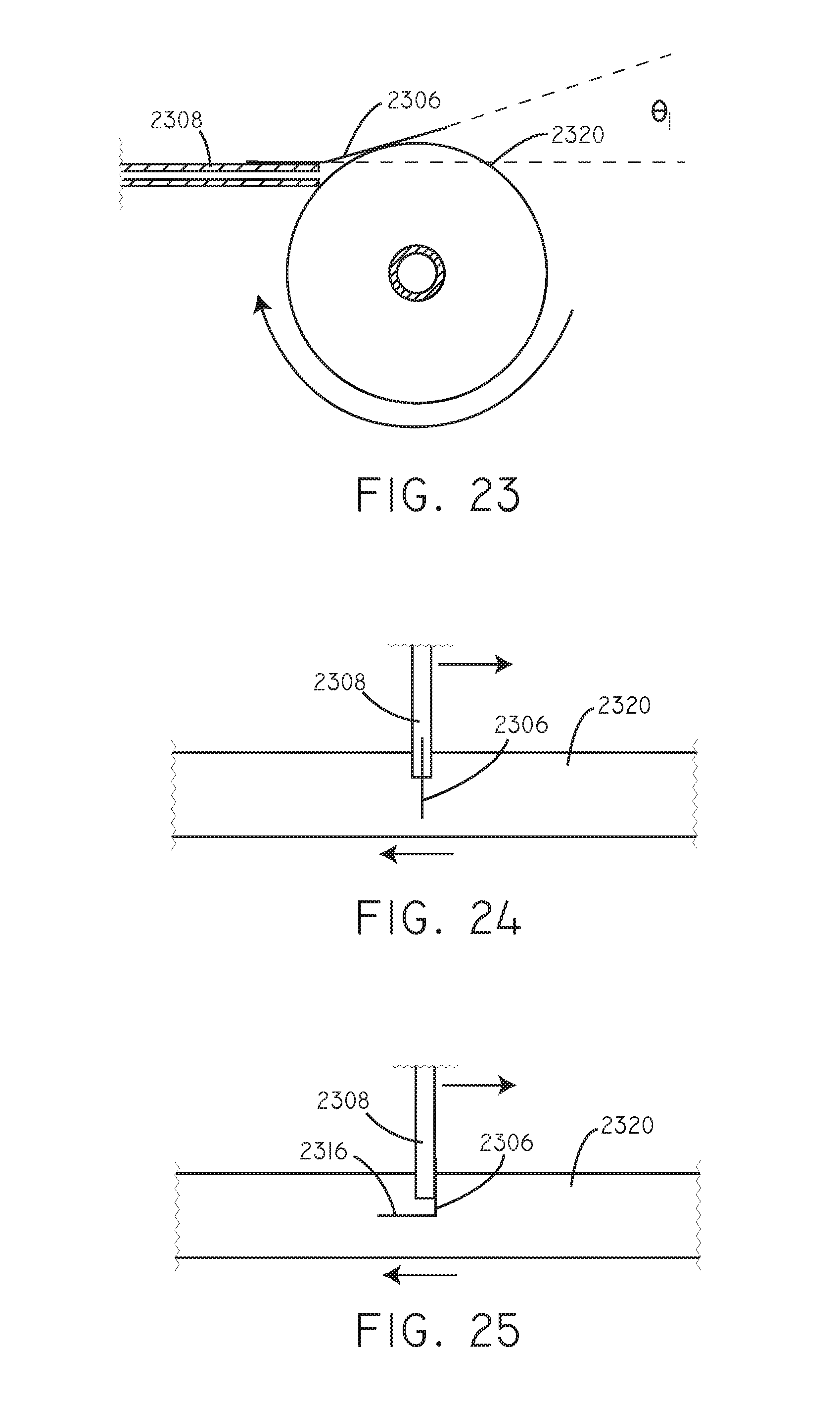
D00015

D00016

D00017

D00018

D00019

XML
uspto.report is an independent third-party trademark research tool that is not affiliated, endorsed, or sponsored by the United States Patent and Trademark Office (USPTO) or any other governmental organization. The information provided by uspto.report is based on publicly available data at the time of writing and is intended for informational purposes only.
While we strive to provide accurate and up-to-date information, we do not guarantee the accuracy, completeness, reliability, or suitability of the information displayed on this site. The use of this site is at your own risk. Any reliance you place on such information is therefore strictly at your own risk.
All official trademark data, including owner information, should be verified by visiting the official USPTO website at www.uspto.gov. This site is not intended to replace professional legal advice and should not be used as a substitute for consulting with a legal professional who is knowledgeable about trademark law.