Heat rejection system for a condenser of a refrigerant loop within an appliance
Avhale , et al. Dec
U.S. patent number 10,502,478 [Application Number 15/384,980] was granted by the patent office on 2019-12-10 for heat rejection system for a condenser of a refrigerant loop within an appliance. This patent grant is currently assigned to Whirlpool Corporation. The grantee listed for this patent is WHIRLPOOL CORPORATION. Invention is credited to Amit A. Avhale, Bruno Boehringer, Darci Cavali, E. C. Pickles, Vijaykumar Sathyamurthi, Lihan Xu, Yan Zhang.


View All Diagrams
| United States Patent | 10,502,478 |
| Avhale , et al. | December 10, 2019 |
Heat rejection system for a condenser of a refrigerant loop within an appliance
Abstract
A refrigerator includes a cabinet defining a refrigerated compartment and a machine compartment. A compressor is disposed within the machine compartment and is adapted to compress a refrigerant within a refrigerant line. A micro-channel condenser is positioned in communication with the compressor and adapted to selectively reject heat from the refrigerant into the machine compartment. A condenser fan is positioned within the machine compartment between the condenser and compressor. The fan is adapted to draw heated air through the condenser and also draw fresh air from an area adjacent the machine compartment and beneath the refrigerated compartment. The heated air and fresh air combine to define mixed air that is directed toward the compressor for cooling the compressor.
| Inventors: | Avhale; Amit A. (St. Joseph, MI), Boehringer; Bruno (Benton Harbor, MI), Cavali; Darci (St. Joseph, MI), Pickles; E. C. (St. Joseph, MI), Sathyamurthi; Vijaykumar (Stevensville, MI), Xu; Lihan (St. Joseph, MI), Zhang; Yan (Iowa City, IA) | ||||||||||
|---|---|---|---|---|---|---|---|---|---|---|---|
| Applicant: |
|
||||||||||
| Assignee: | Whirlpool Corporation (Benton
Harbor, MI) |
||||||||||
| Family ID: | 60915252 | ||||||||||
| Appl. No.: | 15/384,980 | ||||||||||
| Filed: | December 20, 2016 |
Prior Publication Data
| Document Identifier | Publication Date | |
|---|---|---|
| US 20180172335 A1 | Jun 21, 2018 | |
| Current U.S. Class: | 1/1 |
| Current CPC Class: | F25D 11/02 (20130101); F25D 23/003 (20130101); F25B 2400/073 (20130101); F25B 2500/12 (20130101); F25B 39/04 (20130101); F25D 2323/00263 (20130101); F25D 2323/00267 (20130101); F25B 9/04 (20130101); F25D 2323/0022 (20130101); F25D 2323/00261 (20130101) |
| Current International Class: | F25D 11/00 (20060101); F25D 23/00 (20060101); F25D 11/02 (20060101); F25B 9/04 (20060101); F25B 39/04 (20060101) |
References Cited [Referenced By]
U.S. Patent Documents
| 2515825 | July 1950 | Grant |
| 2873041 | February 1959 | Allen |
| 2934023 | April 1960 | Lamkin et al. |
| 3142162 | July 1964 | Herndon, Jr. |
| 3162023 | December 1964 | Smith |
| 3196553 | July 1965 | Deaton et al. |
| 3218730 | November 1965 | Menk et al. |
| 3342961 | September 1967 | Deaton et al. |
| 3653807 | April 1972 | Platt |
| 3805404 | April 1974 | Gould |
| 3953146 | April 1976 | Sowards |
| 3999304 | December 1976 | Doty |
| 4134518 | January 1979 | Menchen |
| 4137647 | February 1979 | Clark, Jr. |
| 4260876 | April 1981 | Hochheiser |
| 4261179 | April 1981 | Dageford |
| 4860921 | August 1989 | Gidseg |
| 4870735 | October 1989 | Jahr, Jr. et al. |
| 5285664 | February 1994 | Chang et al. |
| 5592829 | January 1997 | Kim |
| 5600966 | February 1997 | Valence et al. |
| 5628122 | May 1997 | Spinardi |
| 5666817 | September 1997 | Schulak et al. |
| 5720536 | February 1998 | Jenkins et al. |
| 5927095 | July 1999 | Lee |
| 5946934 | September 1999 | Kim et al. |
| 5979174 | November 1999 | Kim et al. |
| 6041606 | March 2000 | Kim |
| 6073458 | June 2000 | Kim |
| 6401482 | June 2002 | Lee et al. |
| 6598410 | July 2003 | Temmyo et al. |
| 6793010 | September 2004 | Manole |
| 6957501 | October 2005 | Park et al. |
| 6973799 | December 2005 | Kuehl et al. |
| 6983615 | January 2006 | Winders et al. |
| 7008032 | March 2006 | Chekal et al. |
| 7055262 | June 2006 | Goldberg et al. |
| 7093453 | August 2006 | Asan et al. |
| 7117612 | October 2006 | Slutsky et al. |
| 7127904 | October 2006 | Schmid |
| 7143605 | December 2006 | Rohrer et al. |
| 7162812 | January 2007 | Cimetta et al. |
| 7181921 | February 2007 | Nuiding |
| 7207181 | April 2007 | Murray et al. |
| 7216506 | May 2007 | Shin |
| 7254960 | August 2007 | Schmid et al. |
| 7281387 | October 2007 | Daddis, Jr. |
| 7504784 | March 2009 | Asada et al. |
| 7610773 | November 2009 | Rafalovich et al. |
| 7624514 | December 2009 | Konabe et al. |
| 7665225 | February 2010 | Goldberg et al. |
| 7707860 | May 2010 | Hong et al. |
| 7775065 | August 2010 | Ouseph et al. |
| 7866057 | January 2011 | Grunert et al. |
| 7895771 | March 2011 | Prajescu et al. |
| 7934695 | May 2011 | Sim et al. |
| 7980093 | July 2011 | Kuehl et al. |
| 8024948 | September 2011 | Kitamura et al. |
| 8056254 | November 2011 | Loffler et al. |
| 8074469 | December 2011 | Hamel et al. |
| 8079157 | December 2011 | Balerdi Azpilicueta et al. |
| 8099975 | January 2012 | Rafalovich et al. |
| 8104191 | January 2012 | Ricklefs et al. |
| 8166669 | May 2012 | Park et al. |
| 8182612 | May 2012 | Grunert |
| 8240064 | August 2012 | Steffens |
| 8245347 | August 2012 | Goldberg et al. |
| 8266813 | September 2012 | Grunert et al. |
| 8266824 | September 2012 | Steiner |
| 8276293 | October 2012 | Ricklefs et al. |
| 8377224 | February 2013 | Grunert |
| 8382887 | February 2013 | Alsaffar |
| 8434317 | May 2013 | Besore |
| 8438750 | May 2013 | Dittmer et al. |
| 8484862 | July 2013 | Nawrot et al. |
| 8572862 | November 2013 | TeGrotenhuis |
| 8590337 | November 2013 | Lafaire |
| 8601830 | December 2013 | Lee et al. |
| 8615895 | December 2013 | Shin et al. |
| 8656604 | February 2014 | Ediger et al. |
| 8667705 | March 2014 | Shin et al. |
| 8695230 | April 2014 | Noh et al. |
| 8770682 | July 2014 | Lee et al. |
| 8789287 | July 2014 | Kim et al. |
| 8789290 | July 2014 | Grunert |
| 8857071 | October 2014 | Lee et al. |
| 8910394 | December 2014 | Steffens |
| 8915104 | December 2014 | Beihoff et al. |
| 8984767 | March 2015 | Grunert et al. |
| 9010145 | April 2015 | Lim et al. |
| 9022228 | May 2015 | Grunert |
| 9027256 | May 2015 | Kim et al. |
| 9027371 | May 2015 | Beihoff et al. |
| 9052142 | June 2015 | Kim et al. |
| 9062410 | June 2015 | Ahn et al. |
| 9085843 | July 2015 | Doh et al. |
| 9103569 | August 2015 | Cur et al. |
| 9134067 | September 2015 | Ahn et al. |
| 9140472 | September 2015 | Shin et al. |
| 9140481 | September 2015 | Cur et al. |
| 9212450 | December 2015 | Grunert et al. |
| 9249538 | February 2016 | Bison et al. |
| 9267725 | February 2016 | Jeon |
| 9299332 | March 2016 | Je |
| 9303882 | April 2016 | Hancock |
| 9328448 | May 2016 | Doh et al. |
| 9328449 | May 2016 | Doh et al. |
| 9334601 | May 2016 | Doh et al. |
| 9335095 | May 2016 | Bison et al. |
| 9356542 | May 2016 | Ragogna et al. |
| 9359714 | June 2016 | Contarini et al. |
| 9372031 | June 2016 | Contarini et al. |
| 9435069 | September 2016 | Contarini et al. |
| 9487910 | November 2016 | Huang et al. |
| 9506689 | November 2016 | Carbajal et al. |
| 9534329 | January 2017 | Contarini et al. |
| 9534340 | January 2017 | Cavarretta et al. |
| 9605375 | March 2017 | Frank et al. |
| 9644306 | May 2017 | Doh et al. |
| 9663894 | May 2017 | Kim et al. |
| 2004/0139757 | July 2004 | Kuehl et al. |
| 2005/0178139 | August 2005 | Kim |
| 2005/0217139 | October 2005 | Hong |
| 2005/0229614 | October 2005 | Ansted |
| 2006/0070385 | April 2006 | Narayanamurthy et al. |
| 2006/0144076 | July 2006 | Daddis, Jr. et al. |
| 2006/0196217 | September 2006 | Duarte et al. |
| 2007/0033962 | February 2007 | Kang et al. |
| 2008/0141699 | June 2008 | Rafalovich et al. |
| 2008/0196266 | August 2008 | Jung et al. |
| 2008/0307823 | December 2008 | Lee et al. |
| 2009/0071032 | March 2009 | Kreutzfeldt et al. |
| 2009/0158767 | June 2009 | McMillin |
| 2009/0158768 | June 2009 | Rafalovich et al. |
| 2009/0165491 | July 2009 | Rafalovich et al. |
| 2009/0260371 | October 2009 | Kuehl et al. |
| 2009/0266089 | October 2009 | Haussmann |
| 2010/0011608 | January 2010 | Grunert et al. |
| 2010/0101606 | April 2010 | Grunert |
| 2010/0107703 | May 2010 | Hisano et al. |
| 2010/0146809 | June 2010 | Grunert et al. |
| 2010/0154240 | June 2010 | Grunert |
| 2010/0212368 | August 2010 | Kim et al. |
| 2010/0230081 | September 2010 | Becnel et al. |
| 2010/0258275 | October 2010 | Koenig et al. |
| 2010/0288471 | November 2010 | Summerer |
| 2011/0011119 | January 2011 | Kuehl et al. |
| 2011/0030238 | February 2011 | Nawrot et al. |
| 2011/0036556 | February 2011 | Bison et al. |
| 2011/0072849 | March 2011 | Kuehl et al. |
| 2011/0209484 | September 2011 | Krausch et al. |
| 2011/0209860 | September 2011 | Koenig et al. |
| 2011/0277334 | November 2011 | Lee et al. |
| 2011/0280736 | November 2011 | Lee et al. |
| 2012/0017456 | January 2012 | Grunert |
| 2012/0266627 | October 2012 | Lee |
| 2012/0272689 | November 2012 | Elger et al. |
| 2013/0008049 | January 2013 | Patil |
| 2013/0104946 | May 2013 | Grunert et al. |
| 2013/0111941 | May 2013 | Yu et al. |
| 2013/0195678 | August 2013 | Yoo |
| 2013/0212894 | August 2013 | Kim et al. |
| 2013/0255094 | October 2013 | Bommels et al. |
| 2013/0263630 | October 2013 | Doh et al. |
| 2013/0276327 | October 2013 | Doh et al. |
| 2013/0318813 | December 2013 | Hong et al. |
| 2013/0340797 | December 2013 | Bommels et al. |
| 2014/0020260 | January 2014 | Carow et al. |
| 2014/0026433 | January 2014 | Bison et al. |
| 2014/0075682 | March 2014 | Filippetti et al. |
| 2014/0109428 | April 2014 | Kim et al. |
| 2014/0190032 | July 2014 | Lee et al. |
| 2014/0216706 | August 2014 | Melton et al. |
| 2014/0260356 | September 2014 | Wu |
| 2014/0290091 | October 2014 | Bison et al. |
| 2014/0366397 | December 2014 | Wakizaka et al. |
| 2015/0015133 | January 2015 | Carbajal et al. |
| 2015/0033806 | February 2015 | Cerrato et al. |
| 2015/0114600 | April 2015 | Chen et al. |
| 2015/0285551 | October 2015 | Aiken et al. |
| 2015/0308034 | October 2015 | Cavarretta et al. |
| 2015/0322618 | November 2015 | Bisaro et al. |
| 2016/0010271 | January 2016 | Shin et al. |
| 2016/0040350 | February 2016 | Xu et al. |
| 2016/0083894 | March 2016 | Bison et al. |
| 2016/0083896 | March 2016 | Ryoo et al. |
| 2016/0115636 | April 2016 | Kim et al. |
| 2016/0115639 | April 2016 | Kim et al. |
| 2016/0138208 | May 2016 | Bison et al. |
| 2016/0138209 | May 2016 | Kitayama et al. |
| 2016/0145793 | May 2016 | Ryoo et al. |
| 2016/0169540 | June 2016 | Hancock |
| 2016/0178267 | June 2016 | Hao et al. |
| 2016/0186374 | June 2016 | Ryoo et al. |
| 2016/0258671 | September 2016 | Allard et al. |
| 2016/0265833 | September 2016 | Yoon et al. |
| 2016/0282032 | September 2016 | Gomes et al. |
| 2016/0290702 | October 2016 | Sexton et al. |
| 2016/0305696 | October 2016 | Kobayashi et al. |
| 2016/0348957 | December 2016 | Hitzelberger et al. |
| 101967746 | Feb 2011 | CN | |||
| 105177914 | Dec 2015 | CN | |||
| 105696291 | Jun 2016 | CN | |||
| 3147796 | Mar 1983 | DE | |||
| 3738031 | May 1989 | DE | |||
| 4304372 | Aug 1994 | DE | |||
| 4409607 | Oct 1994 | DE | |||
| 10002742 | Jun 2001 | DE | |||
| 10116238 | Mar 2005 | DE | |||
| 10002743 | Jan 2006 | DE | |||
| 102005041145 | Mar 2007 | DE | |||
| 102006018469 | Oct 2007 | DE | |||
| 102007052835 | May 2009 | DE | |||
| 102008033388 | Jan 2010 | DE | |||
| 102008054832 | Jul 2010 | DE | |||
| 102009046921 | May 2011 | DE | |||
| 102012223777 | Jun 2014 | DE | |||
| 112012006737 | Apr 2015 | DE | |||
| 468573 | Jan 1992 | EP | |||
| 0816549 | Jan 1998 | EP | |||
| 999302 | May 2000 | EP | |||
| 1055767 | Nov 2000 | EP | |||
| 1987190 | Nov 2008 | EP | |||
| 2134896 | Dec 2009 | EP | |||
| 2189568 | May 2010 | EP | |||
| 2202349 | Jun 2010 | EP | |||
| 2284310 | Feb 2011 | EP | |||
| 2324152 | May 2011 | EP | |||
| 2341178 | Jul 2011 | EP | |||
| 2386679 | Nov 2011 | EP | |||
| 2455526 | May 2012 | EP | |||
| 2466001 | Jun 2012 | EP | |||
| 2497856 | Sep 2012 | EP | |||
| 2559805 | Feb 2013 | EP | |||
| 2581489 | Apr 2013 | EP | |||
| 2612964 | Jul 2013 | EP | |||
| 2612965 | Jul 2013 | EP | |||
| 2612966 | Jul 2013 | EP | |||
| 2634301 | Sep 2013 | EP | |||
| 2708636 | Mar 2014 | EP | |||
| 2708639 | Mar 2014 | EP | |||
| 2733257 | May 2014 | EP | |||
| 2746455 | Jun 2014 | EP | |||
| 2594687 | Sep 2014 | EP | |||
| 2966215 | Jan 2016 | EP | |||
| 2993427 | Mar 2016 | EP | |||
| 3015594 | May 2016 | EP | |||
| 2468949 | Jun 2016 | EP | |||
| 3034675 | Jun 2016 | EP | |||
| 3241944 | Nov 2017 | EP | |||
| 2087029 | May 1982 | GB | |||
| 11230662 | Aug 1999 | JP | |||
| 2000018796 | Jan 2000 | JP | |||
| 2004053055 | Feb 2004 | JP | |||
| 2004317024 | Nov 2004 | JP | |||
| 2005027768 | Feb 2005 | JP | |||
| 2006017338 | Jan 2006 | JP | |||
| 2006017338 | Jan 2006 | JP | |||
| 2006187449 | Jul 2006 | JP | |||
| 201319623 | Jan 2013 | JP | |||
| 2013085687 | May 2013 | JP | |||
| 20100031929 | Mar 2010 | KR | |||
| 7801958 | Aug 1979 | NL | |||
| 8602149 | Apr 1986 | WO | |||
| 2004106737 | May 2004 | WO | |||
| 2005001357 | Jan 2005 | WO | |||
| 2005032322 | Apr 2005 | WO | |||
| WO-2006137422 | Dec 2006 | WO | |||
| 2007013327 | Feb 2007 | WO | |||
| 2007093461 | Aug 2007 | WO | |||
| 2008077708 | Jul 2008 | WO | |||
| 2008110451 | Sep 2008 | WO | |||
| 2008151938 | Dec 2008 | WO | |||
| 2009031812 | Mar 2009 | WO | |||
| 2009059874 | May 2009 | WO | |||
| 2009077226 | Jun 2009 | WO | |||
| 2009077227 | Jun 2009 | WO | |||
| 2009077291 | Jun 2009 | WO | |||
| 2009089460 | Jul 2009 | WO | |||
| 2010028992 | Mar 2010 | WO | |||
| 2010040635 | Apr 2010 | WO | |||
| 2010071355 | Jun 2010 | WO | |||
| 2010102892 | Sep 2010 | WO | |||
| 2010112321 | Oct 2010 | WO | |||
| 2010118939 | Oct 2010 | WO | |||
| 2011057954 | May 2011 | WO | |||
| 2011061068 | May 2011 | WO | |||
| 2012022803 | Feb 2012 | WO | |||
| 2012065916 | May 2012 | WO | |||
| 2012093059 | Jul 2012 | WO | |||
| 2012101028 | Aug 2012 | WO | |||
| 2012134149 | Oct 2012 | WO | |||
| 2012138136 | Oct 2012 | WO | |||
| 2013129779 | Sep 2013 | WO | |||
| 2013144763 | Oct 2013 | WO | |||
| 2013144764 | Oct 2013 | WO | |||
| 2014001950 | Jan 2014 | WO | |||
| 2014040923 | Mar 2014 | WO | |||
| 2014041097 | Mar 2014 | WO | |||
| 2014076149 | May 2014 | WO | |||
| 2014095790 | Jun 2014 | WO | |||
| 2014102073 | Jul 2014 | WO | |||
| 2014102144 | Jul 2014 | WO | |||
| 2014102317 | Jul 2014 | WO | |||
| 2014102322 | Jul 2014 | WO | |||
| 2014154278 | Oct 2014 | WO | |||
| 2015003742 | Jan 2015 | WO | |||
| 2015028270 | Mar 2015 | WO | |||
| 2015074837 | May 2015 | WO | |||
| 2015082011 | Jun 2015 | WO | |||
| 2015101386 | Jul 2015 | WO | |||
| 2015101387 | Jul 2015 | WO | |||
| 2015101388 | Jul 2015 | WO | |||
| 2015101892 | Jul 2015 | WO | |||
| 2015160172 | Oct 2015 | WO | |||
| 2016006900 | Jan 2016 | WO | |||
| 2016020852 | Feb 2016 | WO | |||
| 2016085432 | Jun 2016 | WO | |||
| 2016095970 | Jun 2016 | WO | |||
| 2016150660 | Sep 2016 | WO | |||
Assistant Examiner: Nouketcha; Lionel
Attorney, Agent or Firm: Price Heneveld LLP
Claims
What is claimed is:
1. A refrigerator comprising: a cabinet defining a refrigerated compartment and a machine compartment at a rear of the cabinet; a compressor disposed within the machine compartment, the compressor adapted to compress a refrigerant within a refrigerant line; a micro-channel condenser positioned in communication with the compressor and adapted to selectively reject heat from the refrigerant into the machine compartment; and a condenser fan positioned within the machine compartment between the micro-channel condenser and the compressor, the condenser fan adapted to draw a stream of heated air through the micro-channel condenser, via a rear vent, and also draw a separate stream of fresh air from a front area of the cabinet and through a fresh air duct that is adjacent the machine compartment, the front area being beneath the refrigerated compartment, wherein the stream of heated air and the separate stream of fresh air combine within a mixing space downstream of the micro-channel condenser to define mixed air that is directed through the condenser fan and toward the compressor for cooling the compressor, wherein the microchannel condenser is positioned within a condenser wall that separates the rear vent from the fresh air duct, and wherein the separate stream of fresh air does not undergo a heat exchange process upstream of the mixing space and under the refrigerated compartment.
2. The refrigerator of claim 1, wherein the micro-channel condenser is positioned at an angle with respect to a rear wall of the machine compartment.
3. The refrigerator of claim 2, wherein a leading edge of the micro-channel condenser engages the rear wall and extends at a 45 degree angle away from the compressor.
4. The refrigerator of claim 3, wherein the machine compartment includes a front wall, the front wall defining the fresh air duct for delivering the separate stream of fresh air from the front area of the cabinet and into the mixing space to be mixed with the stream of heated air.
5. The refrigerator of claim 4, wherein the machine compartment includes a side vent positioned in a first side wall of the cabinet adjacent to the micro-channel condenser, wherein process air is selectively delivered at least from an area external of the machine compartment to the micro-channel condenser via the side vent.
6. The refrigerator of claim 5, wherein the rear wall includes the rear vent that extends from an edge of the rear wall proximate the first side wall to an area proximate the leading edge of the micro-channel condenser.
7. The refrigerator of claim 6, wherein the micro-channel condenser is disposed within the condenser wall, the condenser wall at least partially defining the fresh air duct.
8. The refrigerator of claim 7, further comprising: a sound insulation member disposed proximate the front wall of the machine compartment, wherein the sound insulation member defines a gap that characterizes an air exhaust of the machine compartment.
9. A heat rejection system for an appliance, the heat rejection system comprising: a cabinet defining a machine compartment disposed at a rear of the cabinet and proximate a refrigerated compartment; a linear compressor disposed within the machine compartment, the linear compressor adapted to compress a refrigerant within a refrigerant line, the refrigerant line in thermal communication with the refrigerated compartment; a condenser of the refrigerant line positioned at an angle with respect to an axis of the linear compressor, the condenser in thermal communication with at least an exterior surface of the linear compressor, the condenser adapted to reject heat from the refrigerant and deliver the heat to a stream of process air to define a stream of heated air; and a condenser fan positioned between the condenser and the linear compressor, the condenser fan adapted to draw the stream of heated air from the condenser and also draw a separate stream of fresh air from an area laterally adjacent to the machine compartment and under a front portion of the refrigerated compartment via a fresh air duct, wherein the stream of heated air and the separate stream of fresh air combine within a mixing space defined between the condenser, the fresh air duct and the condenser fan to define mixed air that is directed toward the linear compressor for cooling the exterior surface of the linear compressor, wherein the stream of heated air enters the mixing space through the condenser and the separate stream of fresh air enters the mixing space via the fresh air duct, wherein a condenser wall includes the condenser and separates the stream of process air from the separate stream of fresh air, and wherein the separate stream of fresh air does not undergo a heat exchange process upstream of the fresh air duct and under the front portion of the refrigerated compartment.
10. The heat rejection system of claim 9, wherein the condenser is a micro-channel condenser.
11. The heat rejection system of claim 9, wherein the condenser engages a rear wall of the machine compartment and extends at a 45 degree angle away from the linear compressor.
12. The heat rejection system of claim 9, wherein the machine compartment includes a front wall, the front wall defining the fresh air duct for delivering the separate stream of fresh air to be mixed with the stream of heated air.
13. The heat rejection system of claim 9, wherein the machine compartment includes a side vent positioned in a first side wall of the cabinet adjacent the condenser, wherein the stream of process air is selectively delivered at least from an area external of the machine compartment to the condenser via the side vent.
14. The heat rejection system of claim 13, wherein a rear wall of the machine compartment includes a rear vent that extends from an edge of the rear wall proximate the first side wall to an area proximate a leading edge of the condenser.
15. The heat rejection system of claim 14, wherein the condenser wall at least partially defines the fresh air duct within a front wall of the machine compartment.
16. The heat rejection system of claim 9, further comprising: a sound insulation member disposed proximate a front wall of the machine compartment, wherein the sound insulation member defines a gap that characterizes an air exhaust of the machine compartment.
17. The heat rejection system of claim 9, wherein the condenser fan is positioned to define a rotational axis that is substantially parallel with the axis of the linear compressor.
18. A heat rejection system for an appliance, the heat rejection system comprising: a linear compressor adapted to compress a refrigerant within a refrigerant line; a micro-channel condenser of the refrigerant line positioned at a 45 degree angle with respect to a linear axis of the linear compressor, the micro-channel condenser in thermal communication with at least an exterior surface of the linear compressor, the micro-channel condenser adapted to reject heat from the refrigerant delivered through the micro-channel condenser and deliver the heat to a stream of process air to define a stream of heated air; and a condenser fan positioned between the micro-channel condenser and the linear compressor and proximate a leading edge of the micro-channel condenser, the condenser fan adapted to draw the stream of heated air from the micro-channel condenser and also draw a separate stream of fresh air from a fresh air vent positioned adjacent to a trailing edge of the micro-channel condenser, wherein the stream of heated air and the separate stream of fresh air combine at a mixing space defined between the micro-channel condenser, the fresh air vent and the condenser fan to define mixed air that is directed toward the linear compressor for cooling the exterior surface of the linear compressor, wherein a condenser wall includes the condenser and separates the stream of process air from the separate stream of fresh air, wherein the separate stream of fresh air enters the mixing space directly from the fresh air vent, and wherein the separate stream of fresh air does not undergo a heat exchange process upstream of the fresh air vent.
19. The heat rejection system of claim 18, wherein the linear compressor, micro-channel condenser and condenser fan are positioned within a machine compartment of an appliance cabinet and adjacent to an interior compartment, and wherein a vent space is disposed under the interior compartment and defined by a front wall of the machine compartment, wherein the fresh air vent is defined within the front wall of the machine compartment and the condenser fan draws the separate stream of fresh air from the vent space.
20. The heat rejection system of claim 19, wherein the machine compartment includes the condenser wall that extends from a rear wall of the machine compartment and extends to the front wall of the machine compartment, and wherein the micro-channel condenser is positioned within the condenser wall, and the trailing edge of the micro-channel condenser is at a 45 degree angle distal from the linear compressor, and wherein the condenser fan is positioned to define a rotational axis that is substantially parallel with the linear axis of the linear compressor.
Description
FIELD OF THE DEVICE
The device is in the field of appliances that incorporate a refrigerant loop, and more specifically, a heat rejection system incorporated within a refrigerant loop for rejecting heat within a condenser and also cooling a compressor of the refrigerant loop.
SUMMARY
In at least one aspect, a refrigerator includes a cabinet defining a refrigerated compartment and a machine compartment. A compressor is disposed within the machine compartment and is adapted to compress a refrigerant within a refrigerant line. A micro-channel condenser is positioned in communication with the compressor and is adapted to selectively reject heat from the refrigerant into the machine compartment. A condenser fan is positioned within the machine compartment between the condenser and compressor. The fan is adapted to draw heated air through the condenser and also draw fresh air from an area adjacent the machine compartment and beneath the refrigerated compartment. The heated air and fresh air combine to define mixed air that is directed toward the compressor for cooling the compressor.
In at least another aspect, a heat rejection system for an appliance includes a cabinet defining a machine compartment disposed proximate a refrigerated compartment. A linear compressor is disposed within the machine compartment. The compressor is adapted to compress a refrigerant within a refrigerant line that is in thermal communication with the refrigerated compartment. A condenser of the refrigerant line is positioned at an angle with respect to an axis of the compressor. The condenser is in thermal communication with at least an exterior surface of the compressor. The condenser is adapted to reject heat from the refrigerant and deliver the heat to process air to define heated air. A condenser fan is positioned between the condenser and compressor. The fan is adapted to draw the heated air from the condenser and also draw fresh air from an area laterally adjacent to the machine compartment and under the refrigerated compartment. The heated air and fresh air combine to define mixed air that is directed toward the compressor for cooling the exterior surface of the compressor.
In at least another aspect, a heat rejection system for an appliance includes a linear compressor adapted to compress a refrigerant within a refrigerant line. A micro-channel condenser of the refrigerant line is positioned at a 45 degree angle with respect to a linear axis of the compressor. The condenser is in thermal communication with at least an exterior surface of the compressor. The condenser is adapted to reject heat from the refrigerant delivered through the condenser and deliver the heat to process air to define heated air. A condenser fan is positioned between the condenser and compressor and proximate a leading edge of the condenser. The fan is adapted to draw the heated air from the condenser and also draw fresh air from a fresh air vent positioned adjacent to a trailing edge of the condenser, wherein the heated air and fresh air combine at the fan to define mixed air that is directed toward the compressor for cooling the exterior surface of the compressor.
These and other features, advantages, and objects of the present device will be further understood and appreciated by those skilled in the art upon studying the following specification, claims, and appended drawings.
BRIEF DESCRIPTION OF THE DRAWINGS
In the drawings:
FIG. 1 is a front perspective view of an appliance that includes a refrigerant loop incorporating an aspect of the heat rejection system;
FIG. 2 is a top perspective view of a machine compartment for an appliance incorporating an aspect of the heat rejection system;
FIG. 3 is an enlarged perspective view of the machine compartment of FIG. 2;
FIG. 4 is a schematic top plan view of a prior art machine compartment illustrating temperatures of the prior art machine compartment during operation of the appliance;
FIG. 5 is a top plan view of the machine compartment of FIG. 2 illustrating temperatures within the machine compartment during operation of the the heat rejection system;
FIG. 6 is a top plan view of the prior art machine compartment of FIG. 4 illustrating air velocity within the machine compartment during operation of the prior art appliance;
FIG. 7 is a top plan view of the machine compartment of FIG. 5 illustrating air velocity during operation of the heat rejection system;
FIG. 8 is a schematic perspective view of a front side of a prior art condenser illustrating temperatures on the front side of the condenser during operation of the prior art appliance;
FIG. 9 is a schematic perspective view of the condenser of FIG. 2 illustrating surface temperatures of a front surface of the condenser during operation of the heat rejection system;
FIG. 10 is a rear perspective view of the condenser of a prior art appliance illustrating temperatures on the back side of the prior art condenser during operation of the prior art appliance;
FIG. 11 is a schematic rear perspective view of the condenser of FIG. 2 illustrating surface temperatures of the back surface of the condenser during operation of the heat rejection system;
FIG. 12 is a front perspective view of a prior art condenser illustrating velocity of air entering the prior art condenser;
FIG. 13 is a schematic front perspective view of the condenser of FIG. 9 illustrating the velocity of air entering the condenser during operation of the heat rejection system;
FIG. 14 is a schematic rear perspective view of a prior art condenser illustrating a velocity of air leaving the condenser during operation of the prior art appliance; and
FIG. 15 is a schematic rear perspective view of the condenser of FIG. 11 illustrating the velocity of air leaving the condenser during operation of the heat rejection system.
DETAILED DESCRIPTION OF EMBODIMENTS
For purposes of description herein the terms "upper," "lower," "right," "left," "rear," "front," "vertical," "horizontal," and derivatives thereof shall relate to the device as oriented in FIG. 1. However, it is to be understood that the device may assume various alternative orientations and step sequences, except where expressly specified to the contrary. It is also to be understood that the specific devices and processes illustrated in the attached drawings, and described in the following specification are simply exemplary embodiments of the inventive concepts defined in the appended claims. Hence, specific dimensions and other physical characteristics relating to the embodiments disclosed herein are not to be considered as limiting, unless the claims expressly state otherwise.
As illustrated in FIGS. 1-3, reference numeral 10 generally refers to a condenser incorporated within a refrigerant loop 12 of an appliance 14. The refrigerant loop 12 includes a refrigerant 16 that defines a thermal transfer media for absorbing heat 18 within an evaporator (not shown) and rejecting heat 18 from a condenser 10 in order to cool one or more refrigerated compartments 20 of the appliance 14. According to the various embodiments, the refrigerating appliance 14 can include a cabinet 22 that defines at least one refrigerated compartment 20 and a machine compartment 24. A compressor 26 is disposed within the machine compartment 24.
Referring again to FIGS. 1-3, the compressor 26 is adapted to compress the refrigerant 16 into a vapor that is then delivered to the condenser 10 where the vaporized refrigerant 16 is condensed into a liquid. Through this change in state of refrigerant 16 from a vapor state to a liquid state, heat 18 is rejected from the refrigerant 16 while in the condenser 10. The refrigerant 16 in a liquid state is then moved toward an expansion device where the refrigerant 16 is transferred again into a combination liquid/vapor state to be delivered to the evaporator. Within the evaporator, the refrigerant 16 is transferred back into a vapor state. Through this transfer from a liquid/vapor state to a vapor state of the refrigerant 16, heat 18 is absorbed into the refrigerant 16 at the evaporator. In this manner, the area around the evaporator is cooled, such as within the refrigerated compartment 20. The now vaporized refrigerant 16 is transferred back to the compressor 26 to be re-pressurized for later condensation and rejection of the heat 18 that has been acquired within the evaporator.
As exemplified in FIGS. 1-3, in order to assist the transfer of heat 18 within the condenser 10 and evaporator, the refrigerant loop 12 can include one or more fans 28, including a condenser fan 28. A fan 28 proximate the evaporator assists in the absorption of heat 18 into the refrigerant 16 within the evaporator as air is passed across the surface of the evaporator. Similarly, the rejection of heat 18 from the refrigerant 16 within the condenser 10 is assisted through operation of the condenser fan 28 that passes process air 30 across and/or through portions of the condenser 10 to aid in the rejection of heat 18 from the refrigerant 16.
Referring again to FIGS. 1-3, the condenser 10, typically in the form of a micro-channel condenser 10, can be positioned in communication with the compressor 26. In this manner, the micro-channel condenser 10 can be adapted to selectively reject heat 18 from the refrigerant 16 into the machine compartment 24 and, typically, out of the appliance 14 altogether. The condenser fan 28 is positioned within the machine compartment 24 proximate the condenser 10. It is contemplated that the condenser fan 28 is positioned between the condenser 10 and the compressor 26 such that the fan 28 is adapted to draw heated air 32 through and/or from the condenser 10. The condenser fan 28 is also adapted to draw fresh air 34 from an area, such as a vent space 36, adjacent to the machine compartment 24. This fresh air 34 can be drawn from an area beneath the refrigerated compartment 20. It is contemplated that heated air 32 and fresh air 34 combine to define mixed air 38 that is directed toward the compressor 26 for cooling the compressor 26 during operation of the condenser fan 28. It is contemplated that this configuration of the condenser fan 28 between the micro-channel condenser 10 and the compressor 26 allows for a greater rejection of heat 18 from the condenser 10 and also greater cooling capacity provided to an area proximate the compressor 26.
Referring again to FIGS. 1-3, it is contemplated that the condenser 10 is positioned at an angle with respect to a rear wall 50 of the machine compartment 24. In this configuration, a leading edge 52 of the condenser 10 engages the rear wall 50 and extends at a 45.degree. angle away from the compressor 26. Stated another way, a trailing edge 54 of the condenser 10 is positioned proximate a front wall 56 of the machine compartment 24 and is positioned at a 45.degree. angle distal from the compressor 26. In this configuration, the leading edge 52 of the condenser 10 proximate the rear wall 50 is positioned closer to the compressor 26 than the trailing edge 54 of the condenser 10.
Referring again to FIGS. 1-3, it is contemplated that the machine compartment 24 includes the front wall 56, where the front wall 56 defines a fresh air duct 60 for delivering the fresh air 34 to be mixed with the heated air 32. The angled configuration of the condenser 10 provides a clear space 62 proximate an area of the front wall 56 of the machine compartment 24 to include the fresh air duct 60 within the front wall 56. This fresh air duct 60 allows for the movement of fresh air 34 from the vent space 36 positioned adjacent to the machine compartment 24 and below the refrigerated compartment 20 of the appliance 14.
During operation of the condenser fan 28, the condenser fan 28 draws heated air 32 from the condenser 10 and also draws fresh air 34 from this vent space 36 through the fresh air duct 60. The fresh air 34 and heated air 32 are combined proximate the condenser fan 28 to define mixed air 38 that is delivered to the compressor 26. This mixed air 38 that is cooled through the incorporation of the fresh air 34 from the vent space 36 tends to have a greater cooling capacity for absorbing heat 18 from the compressor 26. This absorption of heat 18 from the compressor 26 allows for greater cooling of the compressor 26 and a more efficient refrigeration system.
Referring again to FIGS. 1-3, to provide greater air flow into the machine compartment 24, the machine compartment 24 can include a side vent 70 positioned within a first side wall 72 of the cabinet 22 adjacent to the condenser 10. It is contemplated that process air 30 is delivered at least from an external area 74 and into the machine compartment 24 and toward the condenser 10 via the side vent 70. This process air 30 is drawn into the condenser 10 through operation of the condenser fan 28. Additionally, the rear wall 50 of the machine compartment 24 includes a rear vent 76 that extends from an edge 78 of the rear wall 50 proximate the first side wall 72 to an area proximate the leading edge 52 of the condenser 10. Again, the angled configuration of the condenser 10, in particular the 45.degree. angle, provides for an enlarged rear vent 76 that increases the amount of process air 30 that can be delivered through the condenser 10 during operation of the condenser fan 28.
Referring again to FIGS. 1-3, to direct the flow of process air 30 from the side vent 70 and rear vent 76 through the condenser 10, it is contemplated that the condenser 10 can be disposed within a condenser wall 90 that extends between the front wall 56 and rear wall 50 of the machine compartment 24. The condenser wall 90 helps to direct the process air 30 through the condenser 10 by preventing the process air 30 from leaking around the condenser 10. It is also contemplated that this condenser wall 90 can at least partially define the fresh air duct 60 within the front wall 56 of the machine compartment 24. In such an embodiment, the condenser wall 90, proximate the trailing edge 54 of the condenser 10, can define a boundary of the fresh air duct 60 such that the size of the fresh air duct 60 can extend from the condenser wall 90 at least to an interior support wall 92 defined proximate the vent space 36 of the appliance 14.
In order to allow for the efficient flow of process air 30, heated air 32, fresh air 34 and mixed air 38 through the machine compartment 24, various air exhaust vents 100 are also included within the machine compartment 24. The machine compartment 24, in order to operate in a quiet manner, includes various sound insulation members 102 that are disposed proximate the front wall 56 of the machine compartment 24. These sound insulation members 102 serve to dampen noise generated by the compressor 26, condenser fan 28 and other motorized components of the appliance 14. It is contemplated that this sound insulation member 102 can define a gap 104 proximate the compressor 26 that characterizes a front air exhaust 106 of the machine compartment 24. This front air exhaust 106, along with the other air exhaust vents 100 of the machine compartment 24, allow for the efficient flow of mixed air 38 out of the machine compartment 24 such that heat 18 from the compressor 26 can be absorbed by the mixed air 38 and moved away from the compressor 26 and out of the appliance 14.
Referring now to FIGS. 1-3, 5, 7, 9, 11, 13 and 15, the heat rejection system 110 for the appliance 14 includes a cabinet 22 that defines the machine compartment 24 disposed proximate the refrigerated compartment 20. The linear compressor 26 is disposed within the machine compartment 24 and is adapted to compress the refrigerant 16 within the refrigerant line 112 into a compressed vapor. The refrigerant line 112 is in thermal communication with the refrigerated compartment 20, via the evaporator, to allow for the absorption of heat 18 from the refrigerated compartment 20 through operation of the evaporator of the refrigerant line 112. The condenser 10 of the refrigerant line 112 is positioned at an angle with respect to a linear axis 118 of the compressor 26. It is contemplated that the condenser 10 is placed in thermal communication with at least an exterior surface 114 of the compressor 26. The condenser 10 is adapted to reject heat 18 from the refrigerant 16 passing through the condenser 10. This heat 18 is rejected from the condenser 10 and delivered into the process air 30 moving through the condenser 10 to define heated air 32 that exits a rear surface 116 of the condenser 10.
Referring again to FIGS. 1-3, 5, 7, 9, 11, 13 and 15, the condenser fan 28 is positioned between the condenser 10 and a compressor 26. The condenser fan 28 is adapted to draw the heated air 32 from the condenser 10 and also draw fresh air 34 from the vent space 36 laterally adjacent to the machine compartment 24 and under the refrigerated compartment 20. The heated air 32 and fresh air 34 are combined to define mixed air 38 that is directed toward the compressor 26 for cooling the exterior surface 114 of the compressor 26. It is contemplated that the condenser fan 28 is positioned to define a rotational axis 130 that is positioned substantially parallel with an axis of the linear compressor 26. Accordingly, the condenser 10 is positioned at a 45.degree. angle with respect to the front and rear walls 56, 50 of the machine compartment 24 and also with respect to the rotational axis 130 of the condenser fan 28 and the linear axis 118 of the linear compressor 26. The positioning of these components of the heat rejection system 110 provides for the efficient rejection of heat 18 from the condenser 10 and, simultaneously, the efficient absorption of heat 18 from the exterior surface 114 of the compressor 26 to prevent overheating of the compressor 26 during operation of the appliance 14.
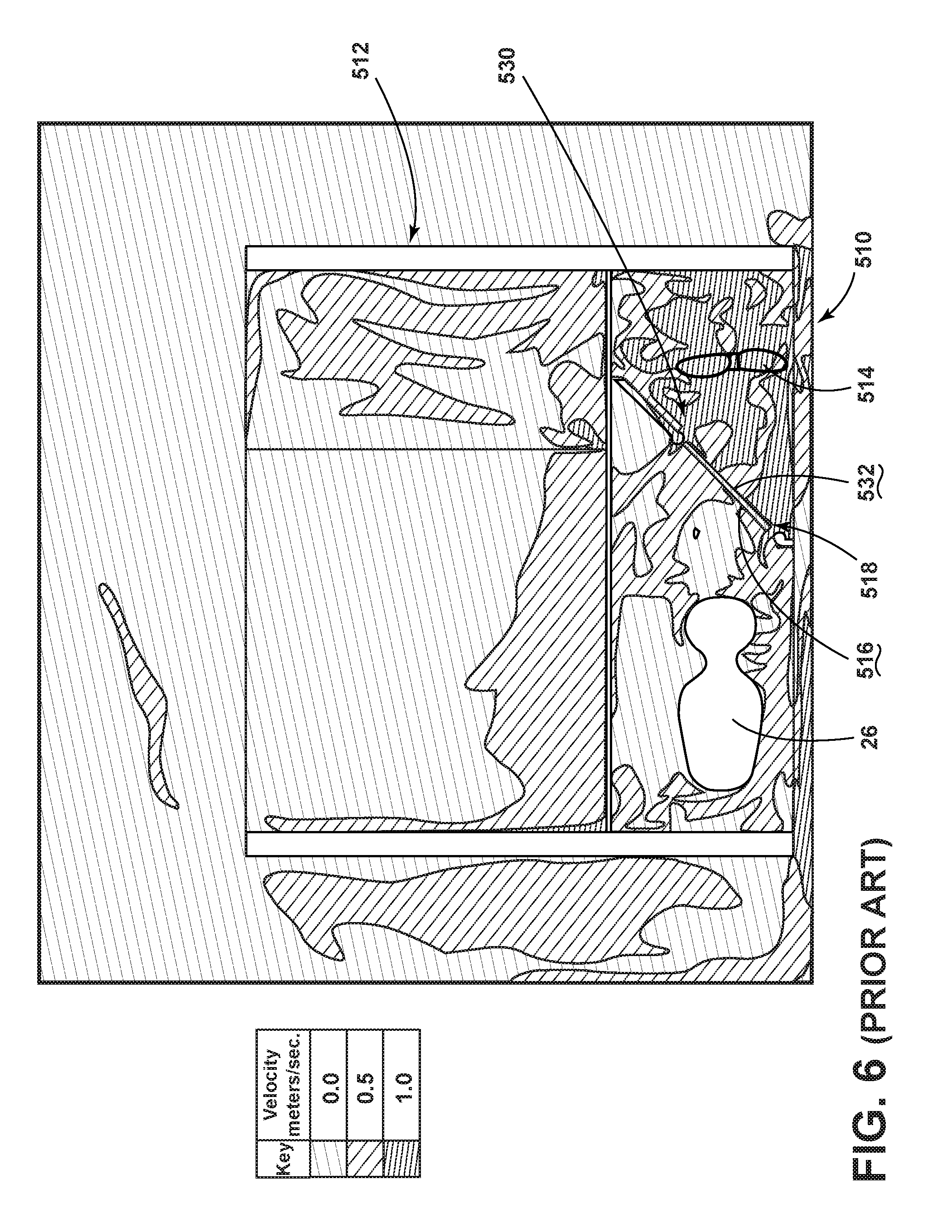
Referring now to the prior art machine compartment 510 exemplified in FIGS. 4 and 6, typical prior art appliances 512 include a blower 514 that is positioned proximate a back side 516 of the prior art condenser 518 such that the prior art condenser 518 is positioned between the compressor 26 and the blower 514. In this configuration, the blower 514 pushes process air 30 into the prior art condenser 518 for collecting the rejected heat 18 from the prior art condenser 518 and moving the air through the prior art machine compartment 510. As exemplified in the temperature plot of FIG. 4, heated air 32 from the prior art condenser 518 is pushed away from the prior art condenser 518 and towards the compressor 26. The heated air 32 is also pushed into areas under the refrigerated compartment 20 of the prior art appliance 512.
Similarly, the prior art velocity plot of FIG. 6 shows that the process air 30 having the highest velocity is contained within an area upstream of the prior art condenser 518 and proximate the back side 516 of the prior art condenser 518. Air leaving the prior art condenser 518 and moving toward the compressor 26 has a much lesser velocity. The higher velocity of air proximate the back side 516 of the condenser 10 indicates that the positioning of the blower 514 in this configuration merely pushes this process air 30 around and within this area upstream of the prior art condenser 518 within the prior art machine compartment 510. Only a portion of this air pushed by the blower 514 is moved through the prior art condenser 518 and to other portions of the prior art machine compartment 510.
Additionally, the velocity plot of FIG. 6 of the prior art appliance 512 shows that air that does move through the prior art condenser 518 is directly only partially toward the compressor 26. A significant portion of this air is pushed toward an area adjacent to the prior art machine compartment 510 under the refrigerated compartment 20. Significantly, the temperature plot of FIG. 4 and the velocity plot of FIG. 6 show that the compressor 26 is surrounded by a significant portion of high temperature air in excess of 110.degree. F. This air is also moving at a very low speed of less than approximately 0.5 meters per second. This slow movement of heated air 32 minimizes the ability of this air to collect heat 18 from the compressor 26 and move this heat 18 away from the prior art appliance 512.
Referring now to FIGS. 5 and 7 illustrating a temperature plot and velocity plot, respectively, of an appliance 14 incorporating the disclosed heat rejection system 110, the condenser fan 28 is positioned to pull heated air 32 from the rear surface 116 of the condenser 10. By pulling air from the rear surface 116 of the condenser 10, the velocity of heated air 32 leaving the condenser 10 is increased to be at minimum of approximately 0.5 meters per second. This heated air 32 is then mixed with the fresh air 34 to form the mixed air 38 that is directed through the condenser fan 28 and toward the compressor 26. Additionally, as exemplified in FIG. 5, the area of highest temperature air of at least 110.degree. F. is limited to the area immediately surrounding the compressor 26. Accordingly, the air surrounding the compressor 26 has a generally lower temperature and a greater capacity for drawing heat 18 from the compressor 26 to be removed from the appliance 14.
Additionally, the configurations of the heat rejection system 110 exemplified in FIGS. 5 and 7 illustrate the in-flow of fresh air 34 from the vent space 36. By mixing this fresh air 34 with the heated air 32, the thermal capacity of the process air 30 moving through the condenser 10 to absorb the rejected heat 18 is increased. Stated another way, the fresh air 34 serves to lower the temperature of the heated air 32 leaving the condenser 10 such that greater amounts of heat 18 can be transferred into the process air 30 to form heated air 32 that is moved toward the condenser fan 28 and ultimately the compressor 26. The addition of the fresh air duct 60 also allows air from the vent space 36 to be moved into the machine compartment 24.
This is in direct contrast to the prior art design exemplified in FIGS. 4 and 6, that clearly shows an increased velocity of heated air 32 moving away from the prior art machine compartment 510 into the space beneath the refrigerated compartment 20. This prior art configuration can have a tendency to cause an increase in temperature within the refrigerated compartment 20 that must be accommodated by the prior art refrigeration loop 530 and the compressor 26 working harder to overcome this infusion of heated air 32 beneath the refrigerated compartment 20.
Referring again to FIGS. 5 and 7, the placement of the condenser fan 28 and the angled configuration of the condenser 10 allows for inclusion of the fresh air duct 60 and an increased size of the rear vent 76. This configuration increases the capacity of the process air 30 and fresh air 34 to receive the rejected heat 18 from the condenser 10 and also increases the capacity of the mixed air 38 to absorb heat 18 from the compressor 26 to better cool the compressor 26 during operation of the appliance 14.
Referring now to FIGS. 8 and 9 that exemplify a side-to-side comparison of the front surface 150 of the prior art condenser 518 (FIG. 8) and the condenser 10 included within the heat rejection system 110 (FIG. 9). The prior art condenser 518 shows a substantially consistent low temperature level along the front side 532 of the prior art condenser 518. Also, the prior art design pushes the process air 30 against the front side 532 of the prior art condenser 518 but little of this air is passed through the prior art condenser 518. Conversely, the condenser 10 of the heat rejection system 110 disclosed herein shows an increased temperature that is indicative of greater heat rejection from the condenser 10 into the process air 30 that is moved through the condenser 10. By drawing the air through the condenser 10 through the downstream placement of the condenser fan 28, the heat rejection system 110 disclosed herein provides for a greater movement of air through the front surface 150 of the condenser 10 and a greater heat rejection rate within the condenser 10 of the heat rejection system 110.
Referring now to FIGS. 10 and 11, these figures illustrate a side-by-side comparison of the temperature of the back side 516 of the prior art condenser 518 (FIG. 10) and the rear surface 116 of the condenser 10 of the heat rejection system 110 (FIG. 11). The prior art condenser 518 shows areas of decreased temperature along the back side 516 that is indicative of lesser heat rejection during operation of the prior art condenser 518. As discussed above, the placement of the blower 514 of the prior art design results in lesser air moving through the prior art condenser 518 and, in turn, less efficient heat rejection of the prior art condenser 518. Conversely, the heat rejection system 110 exemplified in FIG. 11 shows a more consistent and high temperature level of the rear surface 116 of the condenser 10. This consistent temperature is indicative of a more efficient rejection of heat 18 as the process air 30 moves through the condenser 10 to define the heated air 32 that is drawn from the rear surface 116 of the condenser 10 by the condenser fan 28.
Referring now to FIGS. 12-15, these figures illustrate side-by-side comparisons of the air velocities moving through the prior art condenser 518 (FIGS. 12 and 14) and the condenser design of the heat rejection system 110 disclosed herein (FIGS. 13 and 15). The prior art design of FIGS. 12 and 14 clearly show large areas of lower velocity air exiting the back side 516 of the prior art condenser 518 exemplified in FIG. 14. Also, FIG. 12 illustrates the prior art design and the inconsistent air velocity moving through the prior art condenser 518. This inconsistent air flow can produce an inefficient rejection of heat 18 from the prior art condenser 518. Conversely, the heat rejection system 110 disclosed herein, and exemplified in FIGS. 13 and 15 provides for a more consistent velocity of air moving through the condenser 10. FIG. 13 shows a more consistent velocity of air along the front surface 150 of the condenser 10 of the heat rejection system 110. As discussed above, this more consistent velocity of air along the entire front surface 150 of the condenser 10 provides for a more efficient rejection of heat 18 as this process air 30 moves through the condenser 10. Similarly, the back surface of the condenser 10 of the heat rejection system 110 shows a consistent velocity of air along the condenser 10 that is indicative of a consistent heat rejection along the entire back surface of the condenser 10 of the heat rejection system 110.
Referring again to FIGS. 1-3, 5, 7, 9, 11, 13 and 15, the heat rejection system 110 disclosed herein provides for an increased air flow rate within a machine compartment 24 of approximately 2.4 cubic feet of air per minute. This is approximately an 8 percent increase in air flow over the prior art design. Additionally, the placement of the fan 28 downstream of the condenser 10 allows for the inclusion of the fresh air duct 60 within the front wall 56 of the machine compartment 24. This flow of fresh air 34 through the fresh air duct 60 has been found to be approximately 3 cubic feet of air per minute which is added to the heated air 32 from the condenser 10 to define the mixed air 38.
Additionally, the use of the heat rejection system 110 disclosed herein allows for a heat transfer increase of approximately 3 percent. Additionally, heat transfer over the compressor 26 through use of the heat rejection system 110 disclosed herein was approximately 84 percent over that of the prior art design. Because the condenser fan 28 of the heat rejection system 110 is positioned closer to the compressor 26, the condenser fan 28 creates higher velocities of mixed air 38 that help to increase the transfer of heat 18 from the exterior surface 114 of the compressor 26 and into the mixed air 38. As is noted within the prior art design, air is moved away from the prior art machine compartment 510 and into areas proximate the refrigerated compartment 20 of the prior art appliance 512.
Referring again to FIGS. 1-3, 5, 7, 9, 11, 13 and 15, the angled configuration of the condenser 10 within the heat rejection system 110 provides for the placement of the fresh air duct 60 and also an increased size of the rear vent 76 to increase the inflow of process air 30 and fresh air 34 to aid in the transfer of thermal energy. This increased transfer of thermal energy allows for an increased rejection of heat 18 from within the condenser 10 and also an increased cooling of the exterior surface 114 of the compressor 26. Accordingly, the heat rejection system 110 disclosed herein can include the linear compressor 26 that is adapted to compress the refrigerant 16 within the refrigerant line 112. The micro-channel condenser 10 of the refrigerant line 112 is positioned at a 45.degree. angle with respect to a linear axis 118 of the compressor 26. The condenser 10 is in thermal communication with at least an exterior surface 114 of the compressor 26.
It is contemplated that the condenser 10 is also adapted to reject heat 18 from the refrigerant 16 delivered through the condenser 10 and, in turn, deliver the rejected heat 18 into the process air 30 to define heated air 32 that is drawn away from the rear surface 116 of the condenser 10. The condenser fan 28 is positioned between the condenser 10 and the compressor 26 and proximate a leading edge 52 of the condenser 10. The fan 28 is adapted to draw the heated air 32 from the condenser 10 and also draw fresh air 34 from the fresh air duct 60 positioned adjacent to a trailing edge 54 of the condenser 10. The heated air 32 and fresh air 34 combine at the fan 28 to define mixed air 38 that is directed towards the compressor 26 for cooling the exterior surface 114 of the compressor 26. The fresh air duct 60 draws fresh air 34 from the vent space 36 disposed under a refrigerated compartment 20 or other interior compartment of the appliance 14. The fresh air duct 60 is defined by the front wall 56 of the machine compartment 24. As discussed previously, the machine compartment 24 can include the condenser wall 90 that extends from a rear wall 50 of the machine compartment 24 and extends to a front wall 56 of the machine compartment 24. The condenser 10 is positioned within the condenser wall 90 such that the trailing edge 54 of the compressor 26 is positioned at a 45.degree. angle away from the condenser 10. The fan 28 is positioned to define a rotational axis 130 that is substantially parallel with the linear axis 118 of the linear compressor 26. In this manner, rotational axis 130 of the fan 28 is also positioned at a 45.degree. angle with respect to the condenser 10.
Referring again to FIGS. 2 and 3, the machine compartment 24 can also include a fan wall 160 that extends between the front and rear walls 56, 50 of the machine compartment 24. The fan wall 160 serves to direct the mixed air 38 into the condenser fan 28, which is set within the fan wall 160. In this manner, the condenser wall 90 and the fan wall 160 operate to segregate the machine compartment 24 into a plurality of spaces. The condenser wall 90 separates an upstream space 162, which receives the process air 30, from a mixing space 164. The upstream space 162 can include the side vent 70 and the rear vent 76. The mixing space 164 is defined between the condenser wall 90 and the fan wall 160. In the mixing space 164, the fresh air 34 is drawn through the fresh air duct 60 and is combined within the heated air 32 drawn from the condenser 10. This fresh air 34 and heated air 32 are combined in the mixing space 164 to define the mixed air 38 that is drawn through the fan wall 160 via the condenser fan 28. The mixed air 38 is blown by the condenser fan 28 into the compressor 26 space that houses the compressor 26. The compressor space 166 also includes the front air exhaust 106 and the other air exhaust vents 100 for delivering the mixed air 38 out of the machine compartment 24, after at least a portion of the mixed air 38 absorbs heat 18 from the exterior surface 114 of the compressor 26.
Through this configuration of the heat rejection system 110, the condenser fan 28 provides for an increased flow of heated air 32 from the condenser 10 that can be mixed with fresh air 34 from the vent space 36. The heated air 32 and fresh air 34 can be mixed within the mixing space 164 to define mixed air 38 that can be moved toward the compressor 26 within the compressor space 166 for cooling the compressor 26. The mixed air 38 typically has a lower temperature than the heated air 32 as a consequence of being mixed with the fresh air 34 from the fresh air duct 60. By decreasing the temperature of the mixed air 38, this mixed air 38 has a greater thermal capacity for absorbing heat 18 from the exterior surface 114 of the compressor 26. This system provides for greater movement of air and thermal exchange within the machine compartment 24 and also provides for a more efficient operation of the refrigeration system for operating the appliance 14.
It will be understood by one having ordinary skill in the art that construction of the described device and other components is not limited to any specific material. Other exemplary embodiments of the device disclosed herein may be formed from a wide variety of materials, unless described otherwise herein.
For purposes of this disclosure, the term "coupled" (in all of its forms, couple, coupling, coupled, etc.) generally means the joining of two components (electrical or mechanical) directly or indirectly to one another. Such joining may be stationary in nature or movable in nature. Such joining may be achieved with the two components (electrical or mechanical) and any additional intermediate members being integrally formed as a single unitary body with one another or with the two components. Such joining may be permanent in nature or may be removable or releasable in nature unless otherwise stated.
It is also important to note that the construction and arrangement of the elements of the device as shown in the exemplary embodiments is illustrative only. Although only a few embodiments of the present innovations have been described in detail in this disclosure, those skilled in the art who review this disclosure will readily appreciate that many modifications are possible (e.g., variations in sizes, dimensions, structures, shapes and proportions of the various elements, values of parameters, mounting arrangements, use of materials, colors, orientations, etc.) without materially departing from the novel teachings and advantages of the subject matter recited. For example, elements shown as integrally formed may be constructed of multiple parts or elements shown as multiple parts may be integrally formed, the operation of the interfaces may be reversed or otherwise varied, the length or width of the structures and/or members or connector or other elements of the system may be varied, the nature or number of adjustment positions provided between the elements may be varied. It should be noted that the elements and/or assemblies of the system may be constructed from any of a wide variety of materials that provide sufficient strength or durability, in any of a wide variety of colors, textures, and combinations. Accordingly, all such modifications are intended to be included within the scope of the present innovations. Other substitutions, modifications, changes, and omissions may be made in the design, operating conditions, and arrangement of the desired and other exemplary embodiments without departing from the spirit of the present innovations.
It will be understood that any described processes or steps within described processes may be combined with other disclosed processes or steps to form structures within the scope of the present device. The exemplary structures and processes disclosed herein are for illustrative purposes and are not to be construed as limiting.
It is also to be understood that variations and modifications can be made on the aforementioned structures and methods without departing from the concepts of the present device, and further it is to be understood that such concepts are intended to be covered by the following claims unless these claims by their language expressly state otherwise.
The above description is considered that of the illustrated embodiments only. Modifications of the device will occur to those skilled in the art and to those who make or use the device. Therefore, it is understood that the embodiments shown in the drawings and described above is merely for illustrative purposes and not intended to limit the scope of the device, which is defined by the following claims as interpreted according to the principles of patent law, including the Doctrine of Equivalents.
* * * * *
D00000
D00001
D00002
D00003
D00004
D00005
D00006
D00007
D00008
D00009
D00010
D00011
XML
uspto.report is an independent third-party trademark research tool that is not affiliated, endorsed, or sponsored by the United States Patent and Trademark Office (USPTO) or any other governmental organization. The information provided by uspto.report is based on publicly available data at the time of writing and is intended for informational purposes only.
While we strive to provide accurate and up-to-date information, we do not guarantee the accuracy, completeness, reliability, or suitability of the information displayed on this site. The use of this site is at your own risk. Any reliance you place on such information is therefore strictly at your own risk.
All official trademark data, including owner information, should be verified by visiting the official USPTO website at www.uspto.gov. This site is not intended to replace professional legal advice and should not be used as a substitute for consulting with a legal professional who is knowledgeable about trademark law.