Proximity switch having wrong touch adaptive learning and method
Buttolo , et al. Dec
U.S. patent number 10,501,027 [Application Number 16/059,548] was granted by the patent office on 2019-12-10 for proximity switch having wrong touch adaptive learning and method. This patent grant is currently assigned to Ford Global Technologies, LLC. The grantee listed for this patent is Ford Global Technologies, LLC. Invention is credited to Pietro Buttolo, Stuart C. Salter.


| United States Patent | 10,501,027 |
| Buttolo , et al. | December 10, 2019 |
Proximity switch having wrong touch adaptive learning and method
Abstract
A proximity switch assembly and method are provided having wrong touch feedback and adaptive learning. The method includes the steps of detecting multiple attempted activations of a proximity switch that is not allowed, and adjusting one or more settings based on the detected multiple attempted activations to provide adaptive learning. The method also includes the steps of detecting an allowed activation of the proximity switch based on the adjusted one or more settings, and performing an action in response to the detected allowed activation. The proximity switch assembly includes one or more user perceived feedback devices for generating user perceived feedback when an attempted activation that is not allowed is detected.
| Inventors: | Buttolo; Pietro (Dearborn Heights, MI), Salter; Stuart C. (White Lake, MI) | ||||||||||
|---|---|---|---|---|---|---|---|---|---|---|---|
| Applicant: |
|
||||||||||
| Assignee: | Ford Global Technologies, LLC
(Dearborn, MI) |
||||||||||
| Family ID: | 53401246 | ||||||||||
| Appl. No.: | 16/059,548 | ||||||||||
| Filed: | August 9, 2018 |
Prior Publication Data
| Document Identifier | Publication Date | |
|---|---|---|
| US 20180345882 A1 | Dec 6, 2018 | |
Related U.S. Patent Documents
| Application Number | Filing Date | Patent Number | Issue Date | ||
|---|---|---|---|---|---|
| 14635140 | Mar 2, 2015 | 10112556 | |||
| 13288549 | Mar 31, 2015 | 8994228 | |||
| Current U.S. Class: | 1/1 |
| Current CPC Class: | B60R 16/005 (20130101); Y10T 307/766 (20150401); H03K 2217/94026 (20130101); Y10T 307/826 (20150401); H03K 2217/945 (20130101) |
| Current International Class: | B60R 16/00 (20060101) |
References Cited [Referenced By]
U.S. Patent Documents
| 3382588 | May 1968 | Serrell et al. |
| 3544804 | December 1970 | Gaumer et al. |
| 3671750 | June 1972 | Heitmann et al. |
| 3691396 | September 1972 | Hinrichs |
| 3707671 | December 1972 | Morrow et al. |
| 3725589 | April 1973 | Golden |
| 3826979 | July 1974 | Steinmann |
| 3950748 | April 1976 | Busy |
| 4204204 | May 1980 | Pitstick |
| 4205325 | May 1980 | Haygood et al. |
| 4232289 | November 1980 | Daniel |
| 4257117 | March 1981 | Besson |
| 4290052 | September 1981 | Eichelberger et al. |
| 4340813 | July 1982 | Sauer |
| 4370646 | January 1983 | Mahony |
| 4374381 | February 1983 | Ng et al. |
| 4377049 | March 1983 | Simon et al. |
| 4380040 | April 1983 | Posset |
| 4413252 | November 1983 | Tyler et al. |
| 4431882 | February 1984 | Frame |
| 4446380 | May 1984 | Moriya et al. |
| 4453112 | June 1984 | Sauer et al. |
| 4492958 | January 1985 | Minami |
| 4494105 | January 1985 | House |
| 4502726 | March 1985 | Adams |
| 4514817 | April 1985 | Pepper et al. |
| 4613802 | September 1986 | Kraus et al. |
| 4680429 | July 1987 | Murdock et al. |
| 4743895 | May 1988 | Alexander |
| 4748390 | May 1988 | Okushima et al. |
| 4758735 | July 1988 | Ingraham |
| 4821029 | April 1989 | Logan et al. |
| 4855550 | August 1989 | Schultz, Jr. |
| 4872485 | October 1989 | Laverty, Jr. |
| 4899138 | February 1990 | Araki et al. |
| 4901074 | February 1990 | Sinn et al. |
| 4905001 | February 1990 | Penner |
| 4924222 | May 1990 | Antikidis et al. |
| 4954823 | September 1990 | Binstead |
| 4972070 | November 1990 | Laverty, Jr. |
| 5025516 | June 1991 | Wilson |
| 5033508 | July 1991 | Laverty, Jr. |
| 5036321 | July 1991 | Leach et al. |
| 5050634 | September 1991 | Fiechtner |
| 5063306 | November 1991 | Edwards |
| 5108530 | April 1992 | Niebling, Jr. et al. |
| 5153590 | October 1992 | Charlier |
| 5159159 | October 1992 | Asher |
| 5159276 | October 1992 | Reddy, III |
| 5177341 | January 1993 | Balderson |
| 5212621 | May 1993 | Panter |
| 5215811 | June 1993 | Reafler et al. |
| 5225959 | July 1993 | Stearns |
| 5239152 | August 1993 | Caldwell et al. |
| 5270710 | December 1993 | Gaultier et al. |
| 5294889 | March 1994 | Heep et al. |
| 5329239 | July 1994 | Kindermann et al. |
| 5341231 | August 1994 | Yamamoto et al. |
| 5367199 | November 1994 | Lefkowitz et al. |
| 5403980 | April 1995 | Eckrich |
| 5451724 | September 1995 | Nakazawa et al. |
| 5467080 | November 1995 | Stoll et al. |
| 5477422 | December 1995 | Hooker et al. |
| 5494180 | February 1996 | Callahan |
| 5512836 | April 1996 | Chen et al. |
| 5526294 | June 1996 | Ono et al. |
| 5548268 | August 1996 | Collins |
| 5566702 | October 1996 | Philipp |
| 5572205 | November 1996 | Caldwell et al. |
| 5586042 | December 1996 | Pisau et al. |
| 5594222 | January 1997 | Caldwell |
| 5598527 | January 1997 | Debrus et al. |
| 5670886 | September 1997 | Wolff et al. |
| 5681515 | October 1997 | Pratt et al. |
| 5730165 | March 1998 | Philipp |
| 5747756 | May 1998 | Boedecker |
| 5760554 | June 1998 | Bustamante |
| 5790015 | August 1998 | Iitsuka |
| 5790107 | August 1998 | Kasser et al. |
| 5796183 | August 1998 | Hourmand |
| 5801340 | September 1998 | Peter |
| 5825352 | October 1998 | Bisset et al. |
| 5827980 | October 1998 | Doemens et al. |
| 5844287 | December 1998 | Hassan et al. |
| 5864105 | January 1999 | Andrews |
| 5867111 | February 1999 | Caldwell et al. |
| 5874672 | February 1999 | Gerardi et al. |
| 5880538 | March 1999 | Schulz |
| 5917165 | June 1999 | Platt et al. |
| 5920309 | July 1999 | Bisset et al. |
| 5942733 | August 1999 | Allen et al. |
| 5963000 | October 1999 | Tsutsumi et al. |
| 5973417 | October 1999 | Goetz et al. |
| 5973623 | October 1999 | Gupta et al. |
| 5982608 | November 1999 | Kalnitsky et al. |
| 6010742 | January 2000 | Tanabe et al. |
| 6011602 | January 2000 | Miyashita et al. |
| 6031465 | February 2000 | Burgess |
| 6035180 | March 2000 | Kubes et al. |
| 6037930 | March 2000 | Wolfe et al. |
| 6040534 | March 2000 | Beukema |
| 6047964 | April 2000 | Lawandy et al. |
| 6075460 | June 2000 | Minissale et al. |
| 6140914 | October 2000 | Mueller et al. |
| 6157372 | December 2000 | Blackburn et al. |
| 6172666 | January 2001 | Okura |
| 6215476 | April 2001 | Depew et al. |
| 6219253 | April 2001 | Green |
| 6231111 | May 2001 | Carter et al. |
| 6259045 | July 2001 | Imai |
| 6275644 | August 2001 | Domas et al. |
| 6288707 | September 2001 | Philipp |
| 6292100 | September 2001 | Dowling |
| 6297811 | October 2001 | Kent et al. |
| 6310611 | October 2001 | Caldwell |
| 6320282 | November 2001 | Caldwell |
| 6323919 | November 2001 | Yang et al. |
| 6369369 | April 2002 | Kochman et al. |
| 6377009 | April 2002 | Philipp |
| 6379017 | April 2002 | Nakabayashi et al. |
| 6380931 | April 2002 | Gillespie et al. |
| 6404158 | June 2002 | Boisvert et al. |
| 6415138 | July 2002 | Sirola et al. |
| 6427540 | August 2002 | Monroe et al. |
| 6438257 | August 2002 | Morimura et al. |
| 6445192 | September 2002 | Lovegren et al. |
| 6452138 | September 2002 | Kochman et al. |
| 6452514 | September 2002 | Philipp |
| 6456027 | September 2002 | Pruessel |
| 6457355 | October 2002 | Philipp |
| 6464381 | October 2002 | Anderson, Jr. et al. |
| 6466036 | October 2002 | Philipp |
| 6485595 | November 2002 | Yenni, Jr. et al. |
| 6529125 | March 2003 | Butler et al. |
| 6535200 | March 2003 | Philipp |
| 6535694 | March 2003 | Engle et al. |
| 6537359 | March 2003 | Spa |
| 6538579 | March 2003 | Yoshikawa et al. |
| 6559902 | May 2003 | Kusuda et al. |
| 6587097 | July 2003 | Aufderheide et al. |
| 6603306 | August 2003 | Olsson et al. |
| 6607413 | August 2003 | Stevenson et al. |
| 6614579 | September 2003 | Roberts et al. |
| 6617975 | September 2003 | Burgess |
| 6639159 | October 2003 | Anzai |
| 6646398 | November 2003 | Fukazawa et al. |
| 6652777 | November 2003 | Rapp et al. |
| 6654006 | November 2003 | Kawashima et al. |
| 6661239 | December 2003 | Ozick |
| 6661410 | December 2003 | Casebolt et al. |
| 6664489 | December 2003 | Kleinhans et al. |
| 6713897 | March 2004 | Caldwell |
| 6734377 | May 2004 | Gremm et al. |
| 6738051 | May 2004 | Boyd et al. |
| 6740416 | May 2004 | Yokogawa et al. |
| 6756970 | June 2004 | Keely, Jr. et al. |
| 6773129 | August 2004 | Anderson, Jr. et al. |
| 6774505 | August 2004 | Wnuk |
| 6794728 | September 2004 | Kithil |
| 6795226 | September 2004 | Agrawal et al. |
| 6809280 | October 2004 | Divigalpitiya et al. |
| 6812424 | November 2004 | Miyako |
| 6819316 | November 2004 | Schulz et al. |
| 6819990 | November 2004 | Ichinose |
| 6825752 | November 2004 | Nahata et al. |
| 6834373 | December 2004 | Dieberger |
| 6841748 | January 2005 | Serizawa et al. |
| 6847018 | January 2005 | Wong |
| 6847289 | January 2005 | Pang et al. |
| 6854870 | February 2005 | Huizenga |
| 6879250 | April 2005 | Fayt et al. |
| 6884936 | April 2005 | Takahashi et al. |
| 6891114 | May 2005 | Peterson |
| 6891530 | May 2005 | Umemoto et al. |
| 6897390 | May 2005 | Caldwell et al. |
| 6929900 | August 2005 | Farquhar et al. |
| 6930672 | August 2005 | Kuribayashi |
| 6940291 | September 2005 | Ozick |
| 6943705 | September 2005 | Bolender et al. |
| 6960735 | November 2005 | Hein et al. |
| 6962436 | November 2005 | Holloway et al. |
| 6964023 | November 2005 | Maes et al. |
| 6966225 | November 2005 | Mallary |
| 6967587 | November 2005 | Snell et al. |
| 6977615 | December 2005 | Brandwein, Jr. |
| 6987605 | January 2006 | Liang et al. |
| 6993607 | January 2006 | Philipp |
| 6999066 | February 2006 | Litwiller |
| 7030513 | April 2006 | Caldwell |
| 7046129 | May 2006 | Regnet et al. |
| 7053360 | May 2006 | Balp et al. |
| 7063379 | June 2006 | Steuer et al. |
| 7091836 | August 2006 | Kachouh et al. |
| 7091886 | August 2006 | DePue et al. |
| 7098414 | August 2006 | Caldwell |
| 7105752 | September 2006 | Tsai et al. |
| 7106171 | September 2006 | Burgess |
| 7135995 | November 2006 | Engelmann et al. |
| 7146024 | December 2006 | Benkley, III |
| 7151450 | December 2006 | Beggs et al. |
| 7151532 | December 2006 | Schulz |
| 7154481 | December 2006 | Cross et al. |
| 7178405 | February 2007 | Sato |
| 7180017 | February 2007 | Hein |
| 7186936 | March 2007 | Marcus et al. |
| 7205777 | April 2007 | Schulz et al. |
| 7215529 | May 2007 | Rosenau |
| 7218498 | May 2007 | Caldwell |
| 7232973 | June 2007 | Kaps et al. |
| 7242393 | July 2007 | Caldwell |
| 7245131 | July 2007 | Kurachi et al. |
| 7248151 | July 2007 | Mc Call |
| 7248955 | July 2007 | Hein et al. |
| 7254775 | August 2007 | Geaghan et al. |
| 7255466 | August 2007 | Schmidt et al. |
| 7255622 | August 2007 | Stevenson et al. |
| 7269484 | September 2007 | Hein |
| 7279647 | October 2007 | Philipp |
| 7295168 | November 2007 | Saegusa et al. |
| 7295904 | November 2007 | Kanevsky et al. |
| 7339579 | March 2008 | Richter et al. |
| 7342485 | March 2008 | Joehl et al. |
| 7347297 | March 2008 | Ide et al. |
| 7355593 | April 2008 | Hill et al. |
| 7355595 | April 2008 | Bathiche et al. |
| 7358963 | April 2008 | Low et al. |
| 7361860 | April 2008 | Caldwell |
| 7385308 | June 2008 | Yerdon et al. |
| 7445350 | November 2008 | Konet et al. |
| 7447575 | November 2008 | Goldbeck et al. |
| 7479788 | January 2009 | Bolender et al. |
| 7489053 | February 2009 | Gentile et al. |
| 7518381 | April 2009 | Lamborghini et al. |
| 7521941 | April 2009 | Ely et al. |
| 7521942 | April 2009 | Reynolds |
| 7531921 | May 2009 | Cencur |
| 7532202 | May 2009 | Roberts |
| 7535131 | May 2009 | Safieh, Jr. |
| 7535459 | May 2009 | You et al. |
| 7567240 | July 2009 | Peterson, Jr. et al. |
| 7576611 | August 2009 | Glaser |
| 7583092 | September 2009 | Reynolds et al. |
| 7643010 | January 2010 | Westerman et al. |
| 7653883 | January 2010 | Hotelling et al. |
| 7654147 | February 2010 | Witte et al. |
| 7688080 | March 2010 | Golovchenko et al. |
| 7701440 | April 2010 | Harley |
| 7705257 | April 2010 | Arione et al. |
| 7708120 | May 2010 | Einbinder |
| 7710245 | May 2010 | Pickering |
| 7714846 | May 2010 | Gray |
| 7719142 | May 2010 | Hein et al. |
| 7720611 | May 2010 | Lemer |
| 7728819 | June 2010 | Inokawa |
| 7737953 | June 2010 | Mackey |
| 7737956 | June 2010 | Hsieh et al. |
| 7777732 | August 2010 | Herz et al. |
| 7782307 | August 2010 | Westerman et al. |
| 7791594 | September 2010 | Dunko |
| 7795882 | September 2010 | Kirchner et al. |
| 7800590 | September 2010 | Satoh et al. |
| 7821425 | October 2010 | Philipp |
| 7834853 | November 2010 | Finney et al. |
| 7839392 | November 2010 | Pak et al. |
| 7876310 | January 2011 | Westerman et al. |
| 7881940 | February 2011 | Dusterhoff |
| RE42199 | March 2011 | Caldwell |
| 7898531 | March 2011 | Bowden et al. |
| 7920131 | April 2011 | Westerman |
| 7924143 | April 2011 | Griffin et al. |
| 7957864 | June 2011 | Lenneman et al. |
| 7977596 | July 2011 | Born et al. |
| 7978181 | July 2011 | Westerman |
| 7989752 | August 2011 | Yokozawa |
| 8026904 | September 2011 | Westerman |
| 8050876 | November 2011 | Feen et al. |
| 8054296 | November 2011 | Land et al. |
| 8054300 | November 2011 | Bernstein |
| 8076949 | December 2011 | Best et al. |
| 8077154 | December 2011 | Emig et al. |
| 8090497 | January 2012 | Ando |
| 8253425 | August 2012 | Reynolds et al. |
| 8269724 | September 2012 | Sakurai et al. |
| 8279092 | October 2012 | Vanhelle et al. |
| 8283800 | October 2012 | Salter et al. |
| 8330385 | December 2012 | Salter et al. |
| 8339286 | December 2012 | Cordeiro |
| 8386027 | February 2013 | Chuang et al. |
| 8400423 | March 2013 | Chang et al. |
| 8415959 | April 2013 | Badaye |
| 8454181 | June 2013 | Salter et al. |
| 8456180 | June 2013 | Sitarski |
| 8508487 | August 2013 | Schwesig et al. |
| 8514185 | August 2013 | Hotelling |
| 8517383 | August 2013 | Wallace |
| 8537107 | September 2013 | Li |
| 8558346 | October 2013 | Cheng et al. |
| 8570053 | October 2013 | Ryshtun et al. |
| 8575949 | November 2013 | Salter et al. |
| 8599144 | December 2013 | Peng et al. |
| 8619054 | December 2013 | Philipp et al. |
| 8619058 | December 2013 | Ito et al. |
| 8624609 | January 2014 | Philipp et al. |
| 8659414 | February 2014 | Schuk |
| 8688330 | April 2014 | Werner et al. |
| 8724038 | May 2014 | Ganapathi et al. |
| 8736432 | May 2014 | Sitarski |
| 8736577 | May 2014 | Land et al. |
| 8796575 | August 2014 | Salter et al. |
| 8816967 | August 2014 | Lyon et al. |
| 8878438 | November 2014 | Salter et al. |
| 8908034 | December 2014 | Bordonaro |
| 8922340 | December 2014 | Salter et al. |
| 8928336 | January 2015 | Salter et al. |
| 8933708 | January 2015 | Buttolo et al. |
| 8981265 | March 2015 | Jiao et al. |
| 9088282 | July 2015 | Holenarsipur et al. |
| 9110111 | August 2015 | Kapila et al. |
| 9143127 | September 2015 | Tamura et al. |
| 9152278 | October 2015 | Kent et al. |
| 9182837 | November 2015 | Day |
| 9274652 | March 2016 | Chang et al. |
| 9372538 | June 2016 | Pala et al. |
| 9447613 | September 2016 | Salter et al. |
| 9548733 | January 2017 | Buttolo et al. |
| 9654103 | May 2017 | Buttolo et al. |
| 9944237 | April 2018 | Buttolo et al. |
| 10038443 | July 2018 | Salter et al. |
| 2001/0019228 | September 2001 | Gremm |
| 2001/0028558 | October 2001 | Rapp et al. |
| 2002/0040266 | April 2002 | Edgar et al. |
| 2002/0084721 | July 2002 | Walczak |
| 2002/0093786 | July 2002 | Maser |
| 2002/0149376 | October 2002 | Haffner et al. |
| 2002/0167439 | November 2002 | Bloch et al. |
| 2002/0167704 | November 2002 | Kleinhans et al. |
| 2003/0002273 | January 2003 | Anderson, Jr. et al. |
| 2003/0101781 | June 2003 | Budzynski et al. |
| 2003/0122554 | July 2003 | Karray et al. |
| 2003/0128116 | July 2003 | Ieda et al. |
| 2003/0168271 | September 2003 | Massen |
| 2003/0189211 | October 2003 | Dietz |
| 2004/0056753 | March 2004 | Chiang et al. |
| 2004/0090195 | May 2004 | Motsenbocker |
| 2004/0145613 | July 2004 | Stavely et al. |
| 2004/0160072 | August 2004 | Carter et al. |
| 2004/0160234 | August 2004 | Denen et al. |
| 2004/0160713 | August 2004 | Wei |
| 2004/0197547 | October 2004 | Bristow et al. |
| 2004/0246239 | December 2004 | Knowles et al. |
| 2005/0012484 | January 2005 | Gifford et al. |
| 2005/0052429 | March 2005 | Philipp |
| 2005/0068045 | March 2005 | Inaba et al. |
| 2005/0068712 | March 2005 | Schulz et al. |
| 2005/0073317 | April 2005 | Yamamoto et al. |
| 2005/0073425 | April 2005 | Snell et al. |
| 2005/0088417 | April 2005 | Mulligan |
| 2005/0092097 | May 2005 | Shank et al. |
| 2005/0110769 | May 2005 | DaCosta et al. |
| 2005/0137765 | June 2005 | Hein et al. |
| 2005/0183508 | August 2005 | Sato |
| 2005/0218913 | October 2005 | Inaba et al. |
| 2005/0242923 | November 2005 | Pearson et al. |
| 2005/0275567 | December 2005 | DePue et al. |
| 2005/0283280 | December 2005 | Evans, Jr. |
| 2006/0022682 | February 2006 | Nakamura et al. |
| 2006/0038793 | February 2006 | Philipp |
| 2006/0044800 | March 2006 | Reime |
| 2006/0052907 | March 2006 | Hein |
| 2006/0055553 | March 2006 | Fergusson |
| 2006/0082545 | April 2006 | Choquet et al. |
| 2006/0170241 | August 2006 | Yamashita |
| 2006/0238518 | October 2006 | Westerman et al. |
| 2006/0238521 | October 2006 | Westerman et al. |
| 2006/0244733 | November 2006 | Geaghan |
| 2006/0250142 | November 2006 | Abe |
| 2006/0262549 | November 2006 | Schmidt et al. |
| 2006/0267953 | November 2006 | Peterson, Jr. et al. |
| 2006/0279015 | December 2006 | Wang |
| 2006/0287474 | December 2006 | Crawford et al. |
| 2007/0008726 | January 2007 | Brown |
| 2007/0023265 | February 2007 | Ishikawa et al. |
| 2007/0024596 | February 2007 | Takahashi |
| 2007/0051609 | March 2007 | Parkinson |
| 2007/0068790 | March 2007 | Yerdon et al. |
| 2007/0096565 | May 2007 | Breed et al. |
| 2007/0103431 | May 2007 | Tabatowski-Bush |
| 2007/0115759 | May 2007 | Sano |
| 2007/0165005 | July 2007 | Lii et al. |
| 2007/0206668 | September 2007 | Jin |
| 2007/0226994 | October 2007 | Wollach et al. |
| 2007/0232779 | October 2007 | Moody et al. |
| 2007/0247429 | October 2007 | Westerman |
| 2007/0255468 | November 2007 | Strebel et al. |
| 2007/0257891 | November 2007 | Esenther et al. |
| 2007/0271072 | November 2007 | Kovacevich |
| 2007/0291016 | December 2007 | Philipp |
| 2007/0296709 | December 2007 | GuangHai |
| 2008/0012835 | January 2008 | Rimon et al. |
| 2008/0018604 | January 2008 | Paun et al. |
| 2008/0023715 | January 2008 | Choi |
| 2008/0030465 | February 2008 | Konet et al. |
| 2008/0074398 | March 2008 | Wright |
| 2008/0084398 | April 2008 | Ito et al. |
| 2008/0111714 | May 2008 | Kremin |
| 2008/0136792 | June 2008 | Peng et al. |
| 2008/0142352 | June 2008 | Wright |
| 2008/0143681 | June 2008 | XiaoPing |
| 2008/0150625 | June 2008 | Sundstrom |
| 2008/0150905 | June 2008 | Grivna et al. |
| 2008/0158146 | July 2008 | Westerman |
| 2008/0196945 | August 2008 | Konstas |
| 2008/0202912 | August 2008 | Boddie et al. |
| 2008/0205714 | August 2008 | Benkley et al. |
| 2008/0211519 | September 2008 | Kurumado et al. |
| 2008/0231290 | September 2008 | Zhitomirsky |
| 2008/0238650 | October 2008 | Riihimaki et al. |
| 2008/0246723 | October 2008 | Baumbach |
| 2008/0257706 | October 2008 | Haag |
| 2008/0272623 | November 2008 | Kadzban et al. |
| 2009/0009482 | January 2009 | McDermid |
| 2009/0046110 | February 2009 | Sadler et al. |
| 2009/0066659 | March 2009 | He et al. |
| 2009/0079699 | March 2009 | Sun |
| 2009/0108985 | April 2009 | Haag et al. |
| 2009/0115731 | May 2009 | Rak |
| 2009/0120697 | May 2009 | Wilner et al. |
| 2009/0135157 | May 2009 | Harley |
| 2009/0212849 | August 2009 | Reime |
| 2009/0225043 | September 2009 | Rosener |
| 2009/0235588 | September 2009 | Patterson et al. |
| 2009/0236210 | September 2009 | Clark et al. |
| 2009/0251435 | October 2009 | Westerman et al. |
| 2009/0256578 | October 2009 | Wuerstlein et al. |
| 2009/0256677 | October 2009 | Hein et al. |
| 2009/0273563 | November 2009 | Pryor |
| 2009/0273573 | November 2009 | Hotelling |
| 2009/0295409 | December 2009 | Irkliy |
| 2009/0295556 | December 2009 | Inoue et al. |
| 2009/0309616 | December 2009 | Klinghult et al. |
| 2010/0001746 | January 2010 | Duchene et al. |
| 2010/0001974 | January 2010 | Su et al. |
| 2010/0007613 | January 2010 | Costa |
| 2010/0007620 | January 2010 | Hsieh et al. |
| 2010/0013777 | January 2010 | Baudisch et al. |
| 2010/0026654 | February 2010 | Suddreth |
| 2010/0039392 | February 2010 | Pratt et al. |
| 2010/0053087 | March 2010 | Dai et al. |
| 2010/0066391 | March 2010 | Hirasaka et al. |
| 2010/0090712 | April 2010 | Vandermeijden |
| 2010/0090966 | April 2010 | Gregorio |
| 2010/0102830 | April 2010 | Curtis et al. |
| 2010/0103139 | April 2010 | Soo et al. |
| 2010/0110037 | May 2010 | Huang et al. |
| 2010/0117970 | May 2010 | Burstrom et al. |
| 2010/0125393 | May 2010 | Jarvinen et al. |
| 2010/0156814 | June 2010 | Weber et al. |
| 2010/0177057 | July 2010 | Flint et al. |
| 2010/0188356 | July 2010 | Vu et al. |
| 2010/0188364 | July 2010 | Lin et al. |
| 2010/0194692 | August 2010 | Orr et al. |
| 2010/0207907 | August 2010 | Tanabe et al. |
| 2010/0212819 | August 2010 | Salter et al. |
| 2010/0214253 | August 2010 | Wu et al. |
| 2010/0219935 | September 2010 | Bingle et al. |
| 2010/0241431 | September 2010 | Weng et al. |
| 2010/0241983 | September 2010 | Walline et al. |
| 2010/0245286 | September 2010 | Parker |
| 2010/0250071 | September 2010 | Pala et al. |
| 2010/0252048 | October 2010 | Young et al. |
| 2010/0252408 | October 2010 | Yamauchi et al. |
| 2010/0277431 | November 2010 | Klinghult |
| 2010/0280983 | November 2010 | Cho et al. |
| 2010/0286867 | November 2010 | Bergholz et al. |
| 2010/0289754 | November 2010 | Sleeman et al. |
| 2010/0289759 | November 2010 | Fisher et al. |
| 2010/0296303 | November 2010 | Sarioglu et al. |
| 2010/0302200 | December 2010 | Netherton et al. |
| 2010/0309160 | December 2010 | Lin |
| 2010/0315267 | December 2010 | Chung et al. |
| 2010/0321214 | December 2010 | Wang et al. |
| 2010/0321321 | December 2010 | Shenfield et al. |
| 2010/0321335 | December 2010 | Lim et al. |
| 2010/0328261 | December 2010 | Woolley et al. |
| 2010/0328262 | December 2010 | Huang et al. |
| 2011/0001707 | January 2011 | Faubert et al. |
| 2011/0001722 | January 2011 | Newman et al. |
| 2011/0007021 | January 2011 | Bernstein et al. |
| 2011/0007023 | January 2011 | Abrahamsson et al. |
| 2011/0012378 | January 2011 | Ueno et al. |
| 2011/0012623 | January 2011 | Gastel et al. |
| 2011/0018744 | January 2011 | Philipp |
| 2011/0018817 | January 2011 | Kryze et al. |
| 2011/0022393 | January 2011 | Waller et al. |
| 2011/0031983 | February 2011 | David et al. |
| 2011/0034219 | February 2011 | Filson et al. |
| 2011/0037725 | February 2011 | Pryor |
| 2011/0037735 | February 2011 | Land et al. |
| 2011/0039602 | February 2011 | McNamara et al. |
| 2011/0041409 | February 2011 | Newman |
| 2011/0043481 | February 2011 | Bruwer |
| 2011/0050251 | March 2011 | Franke et al. |
| 2011/0050587 | March 2011 | Natanzon et al. |
| 2011/0050618 | March 2011 | Murphy et al. |
| 2011/0050620 | March 2011 | Hristov |
| 2011/0055753 | March 2011 | Horodezky et al. |
| 2011/0057899 | March 2011 | Sleeman et al. |
| 2011/0062969 | March 2011 | Hargreaves et al. |
| 2011/0063425 | March 2011 | Tieman |
| 2011/0074573 | March 2011 | Seshadri |
| 2011/0074684 | March 2011 | Abraham et al. |
| 2011/0074701 | March 2011 | Dickinson |
| 2011/0080365 | April 2011 | Westerman |
| 2011/0080366 | April 2011 | Bolender |
| 2011/0080376 | April 2011 | Kuo et al. |
| 2011/0082616 | April 2011 | Small et al. |
| 2011/0083110 | April 2011 | Griffin et al. |
| 2011/0084707 | April 2011 | Nakayama et al. |
| 2011/0095997 | April 2011 | Philipp |
| 2011/0096025 | April 2011 | Slobodin et al. |
| 2011/0115732 | May 2011 | Coni et al. |
| 2011/0115742 | May 2011 | Sobel et al. |
| 2011/0134047 | June 2011 | Wigdor et al. |
| 2011/0134054 | June 2011 | Woo et al. |
| 2011/0139934 | June 2011 | Giesa et al. |
| 2011/0141006 | June 2011 | Rabu |
| 2011/0141041 | June 2011 | Parkinson et al. |
| 2011/0148803 | June 2011 | Xu |
| 2011/0157037 | June 2011 | Shamir et al. |
| 2011/0157079 | June 2011 | Wu et al. |
| 2011/0157080 | June 2011 | Ciesla et al. |
| 2011/0157089 | June 2011 | Rainisto |
| 2011/0161001 | June 2011 | Fink |
| 2011/0163764 | July 2011 | Shank et al. |
| 2011/0169758 | July 2011 | Aono |
| 2011/0181387 | July 2011 | Popelard |
| 2011/0187492 | August 2011 | Newman et al. |
| 2011/0210755 | September 2011 | Ogawa |
| 2011/0227872 | September 2011 | Huska et al. |
| 2011/0279276 | November 2011 | Newham |
| 2011/0279409 | November 2011 | Salaverry et al. |
| 2011/0309912 | December 2011 | Muller |
| 2012/0007821 | January 2012 | Zaliva |
| 2012/0037485 | February 2012 | Sitarski |
| 2012/0043973 | February 2012 | Kremin |
| 2012/0043976 | February 2012 | Bokma et al. |
| 2012/0055557 | March 2012 | Belz et al. |
| 2012/0062247 | March 2012 | Chang |
| 2012/0062498 | March 2012 | Weaver et al. |
| 2012/0068956 | March 2012 | Jira et al. |
| 2012/0075246 | March 2012 | Chang et al. |
| 2012/0104790 | May 2012 | Plavetich et al. |
| 2012/0126941 | May 2012 | Coggill |
| 2012/0154324 | June 2012 | Wright et al. |
| 2012/0160657 | June 2012 | Mizushima |
| 2012/0161795 | June 2012 | Pfau et al. |
| 2012/0194460 | August 2012 | Kuwabara et al. |
| 2012/0217147 | August 2012 | Porter et al. |
| 2012/0293447 | November 2012 | Heng et al. |
| 2012/0312676 | December 2012 | Salter et al. |
| 2012/0313767 | December 2012 | Sitarski |
| 2012/0319992 | December 2012 | Lee |
| 2013/0002419 | January 2013 | Lee |
| 2013/0024169 | January 2013 | Veerasamy |
| 2013/0033356 | February 2013 | Sitarski et al. |
| 2013/0036529 | February 2013 | Salter et al. |
| 2013/0076121 | March 2013 | Salter et al. |
| 2013/0076375 | March 2013 | Hanumanthaiah et al. |
| 2013/0093500 | April 2013 | Bruwer |
| 2013/0106436 | May 2013 | Brunet et al. |
| 2013/0113544 | May 2013 | Salter et al. |
| 2013/0126325 | May 2013 | Curtis et al. |
| 2013/0147709 | June 2013 | Kim et al. |
| 2013/0162596 | June 2013 | Kono et al. |
| 2013/0170013 | July 2013 | Tonar et al. |
| 2013/0241578 | September 2013 | Satake et al. |
| 2013/0270896 | October 2013 | Buttolo et al. |
| 2013/0270899 | October 2013 | Buttolo et al. |
| 2013/0271159 | October 2013 | Santos et al. |
| 2013/0271182 | October 2013 | Buttolo et al. |
| 2013/0271202 | October 2013 | Buttolo et al. |
| 2013/0271203 | October 2013 | Salter et al. |
| 2013/0271204 | October 2013 | Salter et al. |
| 2013/0291439 | November 2013 | Wuerstlein et al. |
| 2013/0307610 | November 2013 | Salter et al. |
| 2013/0321065 | December 2013 | Salter et al. |
| 2013/0328616 | December 2013 | Buttolo et al. |
| 2014/0002405 | January 2014 | Salter et al. |
| 2014/0116869 | May 2014 | Salter et al. |
| 2014/0145733 | May 2014 | Buttolo et al. |
| 2014/0210257 | July 2014 | Buttolo et al. |
| 2014/0252879 | September 2014 | Dassanayake et al. |
| 2014/0278194 | September 2014 | Buttolo et al. |
| 2014/0278240 | September 2014 | Buttolo et al. |
| 2014/0293158 | October 2014 | Kurasawa et al. |
| 2014/0300403 | October 2014 | Okamoto et al. |
| 2014/0306723 | October 2014 | Salter et al. |
| 2014/0306724 | October 2014 | Dassanayake et al. |
| 2015/0042603 | February 2015 | Takano et al. |
| 2015/0077227 | March 2015 | Salter et al. |
| 2015/0177876 | June 2015 | Ishii et al. |
| 2015/0229305 | August 2015 | Buttolo et al. |
| 2015/0234493 | August 2015 | Parivar et al. |
| 101853099 | Oct 2010 | CN | |||
| 4024052 | Jan 1992 | DE | |||
| 1152443 | Nov 2001 | EP | |||
| 1327860 | Jul 2003 | EP | |||
| 1562293 | Aug 2005 | EP | |||
| 2133777 | Oct 2011 | EP | |||
| 2071338 | Sep 1981 | GB | |||
| 2158737 | Nov 1985 | GB | |||
| 2279750 | Jan 1995 | GB | |||
| 2409578 | Jun 2005 | GB | |||
| 2418741 | Apr 2006 | GB | |||
| 61188515 | Aug 1986 | JP | |||
| 4065038 | Mar 1992 | JP | |||
| 04082416 | Mar 1992 | JP | |||
| 07315880 | Dec 1995 | JP | |||
| 08138446 | May 1996 | JP | |||
| 11065764 | Mar 1999 | JP | |||
| 11110131 | Apr 1999 | JP | |||
| 11260133 | Sep 1999 | JP | |||
| 11316553 | Nov 1999 | JP | |||
| 2000047178 | Feb 2000 | JP | |||
| 2000075293 | Mar 2000 | JP | |||
| 2001013868 | Jan 2001 | JP | |||
| 2006007764 | Jan 2006 | JP | |||
| 2007027034 | Feb 2007 | JP | |||
| 2008033701 | Feb 2008 | JP | |||
| 2010139362 | Jun 2010 | JP | |||
| 2010165618 | Jul 2010 | JP | |||
| 2010218422 | Sep 2010 | JP | |||
| 2010239587 | Oct 2010 | JP | |||
| 2010287148 | Dec 2010 | JP | |||
| 2011014280 | Jan 2011 | JP | |||
| 20040110463 | Dec 2004 | KR | |||
| 20090127544 | Dec 2009 | KR | |||
| 20100114768 | Oct 2010 | KR | |||
| 101258376 | Apr 2013 | KR | |||
| 201032114 | Sep 2010 | TW | |||
| 9636960 | Nov 1996 | WO | |||
| 9963394 | Dec 1999 | WO | |||
| 2006093398 | Sep 2006 | WO | |||
| 2007022027 | Feb 2007 | WO | |||
| 2008121760 | Oct 2008 | WO | |||
| 2009054592 | Apr 2009 | WO | |||
| 2010111362 | Sep 2010 | WO | |||
| 2012032318 | Mar 2012 | WO | |||
| 2012169106 | Dec 2012 | WO | |||
Other References
|
"Clevios P Formulation Guide," 12 pages, www.clevios.com, Heraeus Clevios GmbH, no date provided. cited by applicant . "Introduction to Touch Solutions, White Paper, Revision 1.0 A," Densitron Corporation, 14 pages, Aug. 21, 2007. cited by applicant . Kliffken, Marksu G. et al., "Obstacle Detection for Power Operated Window-Lift and Sunroof Actuation Systems," Paper No. 2001-01-0466, 1 page, .COPYRGT. 2011 SAE International, Published Mar. 5, 2001. cited by applicant . NXP Capacitive Sensors, 1 page, www.nxp.com, copyrighted 2006-2010, NXP Semiconductors. cited by applicant . "Moisture Immunity in QuickSense Studio," AN552, Rev. 0.1 Oct. 2010, 8 pages, Silicon Laboratories, Inc., .COPYRGT. 2010. cited by applicant . "Orgacon EL-P3000, Screen printing Ink Series 3000," 2 pages, AGFA, last updated in Feb. 2006. cited by applicant . "Charge-Transfer Sensing-Based Touch Controls Facilitate Creative Interfaces," www.ferret.com.au, 2 pages, Jan. 18, 2006. cited by applicant . Kiosk Peripherals, "Touch Screen," www.bitsbytesintegrators.com/kiosk-peripherals.html, 10 pages, no date provided. cited by applicant . JVC KD-AVX777 Detachable Front-Panel with Integrated 5.4'' Touch-Screen Monitor, 6 pages, www.crutchfield.com, no date provided. cited by applicant . Ergonomic Palm Buttons, Pepperl+Fuchs, www.wolfautomation.com, 6 pages, no date provided. cited by applicant . "Touch Sensors Design Guide" by ATMEL, 10620 D-AT42-04/09, Revised Apr. 2009, 72 pages, Copyrighted 2008-2009 Atmel Corporation. cited by applicant . "Capacitive Touch Switches for Automotive Applications," by Dave Van Ess of Cypress Semiconductor Corp., published in Automotive DesignLine (http://www.automotivedesignline.com), Feb. 2006, 7 pages. cited by applicant. |
Primary Examiner: Barnie; Rexford N
Assistant Examiner: Ortiz; Elim
Attorney, Agent or Firm: Chea; Vichit Price Heneveld LLP
Parent Case Text
CROSS-REFERENCE TO RELATED APPLICATIONS
This application is a continuation of U.S. patent application Ser. No. 14/635,140, filed Mar. 2, 2015, entitled "PROXIMITY SWITCH HAVING WRONG TOUCH ADAPTIVE LEARNING AND METHOD," now U.S. Pat. No. 10,112,556, which is a continuation-in-part of U.S. patent application Ser. No. 13/288,549, filed on Nov. 3, 2011, now U.S. Pat. No. 8,994,228, entitled "PROXIMITY SWITCH HAVING WRONG TOUCH FEEDBACK." The aforementioned related application is hereby incorporated by reference.
Claims
What is claimed is:
1. A method of activating a proximity switch assembly comprising: detecting repeated attempts to activate a proximity switch that does not result in activation; adjusting one or more settings based on the detected repeated attempts to provide adaptive learning; detecting an allowed activation of the proximity switch based on the adjusted one or more settings; and performing an action in response to the detected allowed activation.
2. The method of claim 1, wherein the step of adjusting one or more settings comprises adjusting an activation threshold.
3. The method of claim 1, wherein the step of adjusting one or more settings comprises adjusting a stable range value that is compared to a signal associated with the proximity switch to determine activation of the proximity switch.
4. The method of claim 1, wherein the step of adjusting one or more settings comprises adjusting a signal ratio of a signal associated with the proximity switch compared to another signal associated with one or more other proximity switches.
5. The method of claim 1 further comprising the step of generating a first user perceived feedback indicative of detection of repeated attempts to activate a proximity switch that does not result in activation.
6. The method of claim 5 further comprising the step of generating a different second user perceived feedback indicative of completion of the action.
7. The method of claim 6 further comprising the step of generating a different third user perceived feedback indicative of detection of an allowed activation of a switch.
8. The method of claim 1, wherein the proximity switch assembly is installed in a vehicle for use by a passenger in the vehicle.
9. The method of claim 1, wherein the proximity switch comprises a capacitive switch comprising one or more capacitive sensors.
10. The method of claim 1, wherein the step of detecting repeated attempts to activate a proximity switch that does not result in activation comprises detecting insufficient signal response during user interface with the proximity switch.
11. A proximity switch assembly comprising: one or more proximity switches; and control circuitry processing an activation field associated with each proximity switch to detect an allowed activation of a proximity switch, said control circuitry further detecting repeated attempts to activate a proximity switch that does not result in activation and adjusting one or more settings based on the attempted activations to provide adaptive learning.
12. The switch assembly of claim 11, wherein the one or more settings comprise an activation threshold.
13. The switch assembly of claim 11, wherein the one or more settings comprise a stable range value that is compared to a signal associated with the proximity switch to determine activation of the proximity switch.
14. The switch assembly of claim 11, wherein the one or more settings comprise a signature ratio of a signal associated with the proximity switch compared to another signal associated with one or more other proximity switches.
15. The switch assembly of claim 11 further comprising a feedback device for generating a first user perceived feedback when repeated attempts to activate a proximity switch that does not result in activation is detected.
16. The switch assembly of claim 15, wherein the feedback device generates a second different user perceived feedback indicative of completion of the action.
17. The switch assembly of claim 16, wherein the feedback device generates a different third user perceived feedback indicative of detection of an allowed activation of a switch.
18. The switch assembly of claim 11, wherein the plurality of proximity switches are installed in vehicle for use by a passenger in the vehicle.
19. The switch assembly of claim 11, wherein each of the proximity switches comprises a capacitive switch comprising a capacitive sensor.
Description
FIELD OF THE INVENTION
The present invention generally relates to switches, and more particularly relates to proximity switches with enhanced user feedback and user interaction.
BACKGROUND OF THE INVENTION
Automotive vehicles are typically equipped with various user actuatable switches, such as switches for operating devices including powered windows, headlights, windshield wipers, moonroofs or sunroofs, interior lighting, radio and infotainment devices, and various other devices. Generally, these types of switches need to be actuated by a user in order to activate or deactivate a device or perform some type of control function. Proximity switches, such as capacitive switches, employ one or more proximity sensors to generate a sense activation field and sense changes to the activation field indicative of user actuation of the switch, typically caused by a user's finger in close proximity or contact with the sensor. Capacitive switches are typically configured to detect user actuation of the switch based on comparison of the sense activation field to a threshold.
Switch assemblies often employ a plurality of capacitive switches in close proximity to one another and require that a user select a single desired capacitive switch to perform the intended operation. Users frequently activate the wrong switch, such as activating multiple switches simultaneously, particularly when the user interface devices are small and the switches are close together. In some applications, such as in an automobile, the driver of the vehicle has limited ability to view the switches due to driver distraction and therefore may inadvertently operate the switch in a wrong manner. Accordingly, it is desirable to provide for a proximity switch arrangement, which enhances the use of the proximity switches by a person, such as a driver in a vehicle.
SUMMARY OF THE INVENTION
According to one aspect of the present invention, a method of activing a proximity switch assembly is provided. The method includes the steps of detecting multiple attempted activations of a proximity switch that is not allowed. The method also includes the steps of adjusting one or more settings based on the detected multiple attempted activations to provide adaptive learning and detecting an allowed activation of the proximity switch based on the adjusted one or more settings. The method further includes the step of performing an action in response to the detected allowed activation.
According to another aspect of the present invention, a proximity switch assembly is provided. The proximity switch assembly includes one or more proximity switches and control circuitry processing an activation field associated with each proximity switch to detect an allowed activation of a proximity switch. The control circuitry further detects multiple attempted activations of a switch that is not allowed and adjusts one or more settings based on the attempted activation to provide adaptive learning.
These and other aspects, objects, and features of the present invention will be understood and appreciated by those skilled in the art upon studying the following specification, claims, and appended drawings.
BRIEF DESCRIPTION OF THE DRAWINGS
In the drawings:
FIG. 1 is a perspective view of a passenger compartment of an automotive vehicle having an overhead console employing a proximity switch assembly having user perceived feedback and adaptive learning, according to one embodiment;
FIG. 2 is an enlarged view of the overhead console and proximity switch assembly shown in FIG. 1;
FIG. 3 is an enlarged cross-sectional view taken through line in FIG. 2 showing the proximity switches in relation to a user's finger;
FIG. 4 is a block diagram illustrating the proximity switch assembly having user perceived feedback and adaptive learning, according to one embodiment;
FIG. 5 is a flow diagram illustrating a routine for providing user perceived feedback based on activation of the proximity switches, according to one embodiment;
FIG. 6A is a front view of a switch assembly showing a user's finger repeatedly attempting to activate a proximity switch with wrong touch;
FIG. 6B is a graph illustrating adaptive learning by adjusting the signature ratio to allow activation during the wrong touch of FIG. 6A, according to one embodiment;
FIG. 7 is a graph illustrating adaptive learning by adjusting the activation threshold setting, according to a another embodiment;
FIG. 8 is a graph illustrating adaptive learning by adjusting the signal stable range to allow activation following a wrong touch, according to another embodiment;
FIG. 9 is a graph illustrating adaptive learning by adjusting the minimum rate, according to a further embodiment;
FIG. 10 is a flow diagram illustrating a method of proximity switch activation control that adjusts one or more settings based on multiple attempted activations of a switch that is not allowed; and
FIG. 11 is a flow diagram illustrating the relaxed activation settings subroutine of FIG. 10.
DETAILED DESCRIPTION OF THE PREFERRED EMBODIMENTS
As required, detailed embodiments of the present invention are disclosed herein; however, it is to be understood that the disclosed embodiments are merely exemplary of the invention that may be embodied in various and alternative forms. The figures are not necessarily to a detailed design; some schematics may be exaggerated or minimized to show function overview. Therefore, specific structural and functional details disclosed herein are not to be interpreted as limiting, but merely as a representative basis for teaching one skilled in the art to variously employ the present invention.
Referring to FIGS. 1 and 2, the interior of an automotive vehicle 10 is generally illustrated having a passenger compartment and a switch assembly 20 employing a plurality of proximity switches 22 having user perceived feedback and adaptive learning, according to one embodiment. The vehicle 10 generally includes an overhead console 12 assembled to the headliner on the underside of the roof or ceiling at the top of the vehicle passenger compartment, generally above the front passenger seating area. The switch assembly 20 has a plurality of proximity switches 22 arranged close to one another in the overhead console 12, according to one embodiment. The various proximity switches 22 may control any of a number of vehicle devices and functions, such as controlling movement of a sunroof or moonroof 16, controlling movement of a moonroof shade 18, controlling activation of one or more lighting devices such as interior map/reading and dome lights 32, and various other devices and functions. However, it should be appreciated that the proximity switches 22 may be located elsewhere on the vehicle 10, such as in the dash panel, on other consoles such as a center console, integrated into a touch screen display for a radio or infotainment system such as a navigation and/or audio display, or located elsewhere onboard the vehicle 10 according to various vehicle applications.
The proximity switches 22 are shown and described herein as capacitive switches, according to one embodiment. Each proximity switch 22 includes at least one proximity sensor that provides a sense activation field to sense contact or close proximity of a user in relation to the one or more proximity sensors, such as a swiping motion by a user's finger. Thus, the sense activation field of each proximity switch 22 is a capacitive field in the exemplary embodiment and the user's finger has electrical conductivity and dielectric properties that cause a change or disturbance in the sense activation field as should be evident to those skilled in the art. However, it should also be appreciated by those skilled in the art that additional or alternative types of proximity sensors can be used, such as, but not limited to, inductive sensors, optical sensors, temperatures sensors, resistive sensors, the like, or a combination thereof. Exemplary proximity sensors are described in the Apr. 9, 2009, ATMEL.RTM. Touch Sensors Design Guide, 10620 D-AT42-04/09, the entire reference hereby being incorporated herein by reference.
The proximity switches 22 shown in FIGS. 1 and 2 each provide control of a vehicle component or device or provide a designated control function. One or more of the proximity switches 22 may be dedicated to controlling movement of a sunroof or moonroof 16 so as to cause the moonroof 16 to move in an open or closed direction, tilt the moonroof, or stop movement of the moonroof based upon a control algorithm. One or more other proximity switches 22 may be dedicated to controlling movement of a moonroof shade 18 between open and closed positions. Each of the moonroof 16 and shade 18 may be actuated by an electric motor in response to actuation of the corresponding proximity switch 22. Other proximity switches 22 may be dedicated to control other devices, such as turning an interior map/reading light on, turning an interior map/reading light off, turning a dome lamp on or off, unlocking a trunk, opening a rear hatch, or for defeating a door light switch. Additional controls via the proximity switches 22 may include actuating door power windows up and down. Various other vehicle controls may be controlled by way of the proximity switches 22 described herein.
The proximity switch assembly 20 includes one or more user perceived feedback devices for generating user perceived feedback when an attempted activation of a proximity switch is not allowed. The user perceived feedback devices may include an audible tone generator such as one or more vehicle speakers 36 shown installed in the doors of the vehicle. Any of the vehicle equipped speakers or other audible tone generators may be employed to provide an audible tone to the user upon wrong touch activation of the switch assembly 20. Other feedback devices may include a visual display, such as navigation or radio display 38 shown installed in the vehicle. The visual display 38 may display text or icons as feedback indicative of a wrong touch of the proximity switch assembly 20. Further feedback devices may include a vibratory or tactile generator 40 for providing a vibration as a feedback. The vibratory generator may be implemented as an eccentric motor, according to one embodiment. The vibratory generator 40 may be integrated within the proximity switch assembly 20 or within the individual proximity switches 22 to generate vibration to the user's finger, according to one embodiment. According to other embodiments, the vibratory generator 40 may be located within the steering wheel 14 of the vehicle, the vehicle seat, or other point of contact with the user to provide a vibration that is perceived by the user upon wrong touch of the proximity switch assembly 20. A further feedback device may include one or more indicator lights 42 for providing a visual light indication as a feedback indicative of a wrong touch activation of the proximity switch assembly. The indicator light 42 may include a dedicated light installed in the instrument panel cluster, as shown, or other dedicated or shared lighting devices including mood or ambient lighting, dome lighting, map reading lights, electronic display lighting, and other lighting available and viewable by a user of the proximity switch assembly 20.
Referring to FIG. 3, a portion of the proximity switch assembly 20 is illustrated having three serial arranged proximity switches 22 in close relation to one another in relation to a user's finger 58 during a wrong touch activation of the switch assembly 20. Each proximity switch 22 includes one or more proximity sensors mounted on a substrate 54 for generating a sense activation field 50. A contact surface 52 such as a film covers the proximity switches 22. In the embodiment shown, adjacent sense activation fields 50 generated by adjacent proximity switches 22 overlap slightly. When a user, such as the user's finger 58, enters the activation field, the proximity switch assembly 20 detects the disturbance to the activation field and determines an activation of the corresponding proximity switch 22. However, when a user simultaneously contacts two switches, such that the finger 58 simultaneously enters activation fields 50 for adjacent proximity sensors, a wrong touch condition may exist. When a wrong touch condition is initially detected, activation of the proximity switches is not allowed and a user perceived feedback may be provided to the user to let the user know of the wrong touch condition. A wrong touch condition may occur when a user attempted to interact with the proximity switch 22, but no clear activation is detected. Examples of wrong touch conditions include one or more of the following: the user simultaneously contacting two switches; an insufficient signal response is detected due to poor conductive qualities of the fingers, such as a finger containing lotion or having a glove covering the finger; and a finger that slowly approaches a switch, especially one having a glove on the finger. It should be appreciated that other examples of wrong touch conditions may exist.
Referring to FIG. 4, the proximity switch assembly 20 is illustrated according to one embodiment. A plurality of proximity switches 22 are shown providing inputs to a controller 24. The controller 24 may include control circuitry, such as a microprocessor 26 and memory 28. The control circuitry may include sense control circuitry processing the activation field to sense user activation of the switch by comparing the activation field to a threshold. It should be appreciated that other analog and/or digital control circuitry may be employed to process the activation field, determine user activation, initiate an action, generate user perceived feedback and execute and implement adaptive learning. The controller 24 provides an output signal to one or more devices that are configured to perform dedicated actions responsive to correct activation of a proximity switch. For example, the one or more devices may include a moonroof 16 having a motor to move the moonroof panel between open and closed and tilt positions, a moonroof shade 18 that moves between open and closed positions, and light devices 34 that may be turned on and off. Other devices may be controlled such as a radio for performing on and off functions, volume control, scanning, and other types of devices for performing other dedicated functions. One of the proximity switches 22 may be dedicated to actuating the moonroof closed, another proximity switch 22 may be dedicated to actuating the moonroof open, and a further switch 22 may be dedicated to actuating the moonroof to a tilt position, all of which would cause a motor to move the moonroof to a desired position. The moonroof shade 18 may be opened in response to one proximity switch 22 and may be closed responsive to another proximity switch 22.
The controller 20 provides an output signal to one or more user perceived feedback devices 30 to generate a perceived feedback to a user. According to one embodiment, the user perceived feedback devices 30 may include an audible tone generator 36, such as a speaker, for generating an audible signal such as a tone and/or voice commands. According to another embodiment, the one or more user feedback devices 30 may include a tactile vibratory generator 40 for generating a vibration of the proximity switch pad or some other device or surface, such as a steering wheel or an armrest or seat upon which the user is seated in. According to a further embodiment, the feedback device 30 may include one or more indicator lights 42 for providing a light output. Further, the feedback device 30 may employ a visual display 38 to display feedback information in the form of text or icons. The user perceived feedback devices 30 provide an audible tone, vibration, light and/or visual display to the user in response to activation of the one or more proximity switches.
When a user attempts to activate a switch with a wrong touch condition, a first or wrong touch feedback may be generated to indicate to the user that the switch was wrongly activated. A wrong touch activation may include simultaneous activation of two switches, according to one embodiment. When a wrong touch is repeatedly detected, the switch assembly may adaptively learn the intended switch activation and adjust one or more settings to allow activation of a switch. The user perceived feedback device 30 may generate a second or action completed feedback to the user when the action actuated has completed the action. A third or right touch feedback may be generated when an allowed activation of a proximity switch is detected.
The controller 42 processes one or more routines including routine 100 to generate user perceived feedback based on activation of one or more of the proximity switches 22. The controller monitors the proximity switches for an activation of one or more of the proximity switches and performs the dedicated action when a right touch activation is detected. When an activation is properly detected, a right touch feedback may be provided by any of the feedback devices 30. The controller 42 also monitors for proximity sensors 22 for the presence of a wrong touch activation of the proximity sensor assembly and generates a wrong touch feedback in response thereto. The wrong touch condition may be due to an ambiguous input such as a simultaneous activation of two or more switches, or may be the activation of a switch for which an action cannot be performed. The feedback generated for a wrong touch is different than the feedback generated for a right touch so that the user may decipher between wrong touch and right touch activations of the proximity switch assembly 20. The controller 42 further determines when the action actuated by the activation of a proximity switch is complete and provides in response thereto an action complete feedback via one or more of the feedback devices 30. The action complete feedback is different than the wrong touch feedback and the right touch feedback such that a user may decipher the differences therebetween.
Referring to FIG. 5, the control routine 100 is illustrated, according to one embodiment. Routine 100 begins at step 102 and proceeds to step 104 to monitor the proximity sensor outputs for each switch. Next, at decision step 106, routine 100 detects activation of one or more proximity switches and, if no activation is detected, returns to step 104. If the activation of one or more proximity switches is detected, routine 100 proceeds to decision step 108 to look for an ambiguous input. The ambiguous input may include the attempted simultaneous activation of two or more proximity switches. If an ambiguous input is detected, routine 100 generates the wrong touch feedback at step 110 and then returns at step 122. If no ambiguous input is detected, routine 100 proceeds to decision step 112 to determine if the action dedicated to that activated proximity switch is allowed and, if not, generates a wrong touch feedback at step 110, and then returns at step 122. Accordingly, either an ambiguous input or activation or a switch for which an action is not allowed are deemed to be wrong touch activations for which an action cannot be performed. In response thereto, a wrong touch feedback is generated by one or more of the feedback devices including the audible tone generator 36, visual display 38, vibratory generator 40, and indicator light(s) 42. The wrong touch feedback may be a user perceived alert type feedback that a user would perceive as an incorrect activation of the proximity switch assembly 20.
If no wrong touch activation exists, routine 100 proceeds to step 114 to generate a right touch feedback. A right touch feedback may be generated with any one or more of the feedback devices to provide a second more pleasant feedback recognizable by a user as proper activation of a proximity switch for which an action can be performed. At step 116, the action responsive to the switch activation is performed. Next, routine 100 proceeds to step 118 to determine if the action is complete and, if not, returns to step 122. If the action is complete, routine 100 then generates an action complete feedback via one or more of the feedback devices 30. The action complete feedback is a third pleasant tone feedback recognizable by a user as completion of the action in response to activation of the proximity switch.
According to another embodiment, the right touch feedback may be generated to provide multiple levels of feedback, such as a progressive feedback. For example, when two signal channels for adjacent capacitive switches are at a substantially similar signal level, a wrong touch feedback may be provided at a first level, however, when one channel is significantly greater than the other channel, the wrong touch feedback may be at a second lower level relative to the first feedback. This may indicate to the operator that the wrong touch is not as severe or significant when one signal channel is substantially greater than another indicative that the correct signal was substantially activated. This may help to provide feedback to the user so that the user may understand why the input is deemed wrong and how to modify hand posture to get the action recognized correctly. According to another example, for a non-allowed action, multiple levels of progressive feedback may be provided, such as to provide a first higher feedback when a user attempts to open a moonroof while the vehicle is in a car wash and provides a second lower feedback when the user is trying to close a moonroof that is already closed.
A proximity switch assembly and a method of activating a proximity switch assembly that detects multiple attempted activations of one or more proximity switches that is not allowed and adjusts one or more settings based on the detected multiple attempted activations to provide adaptive learning is further provided according to another embodiment. The proximity switch assembly and method advantageously detects multiple or repeated failed attempts to activate a proximity switch and adaptively learns from the multiple failed attempts and adjusts one or more settings to enable activation of the switch. Each time a wrong touch condition is detected, one or more feedbacks may be generated as described above. If a user repeatedly tries to interact with the proximity switch assembly while in the wrong touch mode, the proximity switch assembly and method can adjust one or more settings to adapt to the user's interface signature. The proximity switch assembly and method can adjust the one or more settings autonomously to allow for less clean interface (e.g., touch) or may further prompt the user for guidance and request from the user which type of activation was intended. The attempted activation that is not allowed is referred to as a wrong touch and may occur with the simultaneous activation of two or more switches which may be caused by a user's finger overlapping the activation fields associated with two or more proximity sensors associated with two adjacent proximity switches. Other wrong touch conditions include attempted activations by a user having a finger with poor conductive properties, such as a finger having lotion or covered by an electrically insulative glove which may result in insufficient signal response. Further attempted activations for wrong touch may include a user's finger slowly approaching a proximity switch, particularly when the finger is covered by a glove.
In response to detecting multiple attempted activations of a wrong touch condition, the system and method advantageously may adjust one or more settings to tune the proximity switch assembly to thereby provide adaptive learning. The adjustment of one or more settings may include adjusting one or more activation thresholds that are used to determine switch activation, adjusting a clean signal band, adjusting a signal or signature ratio which defines how the signal is distributed amongst the sensors, adjusting a minimum rate or rise time of the signal, and other potential adjustments of settings associated with determining an activation of a proximity switch. Examples of various settings used for determining switch activation that can be adjusted are disclosed in U.S. Patent Application Publication No. 2013/0270896 A1 entitled "PROXIMITY SWITCH ASSEMBLY AND ACTIVATION METHOD," which is hereby incorporated herein by reference.
The new adjusted setting(s) can be active for a predetermined time, such as until a certain number of consecutive clear activations is detected or may be permanently adjusted. The adjusted setting(s) may be used on one or all of a plurality of proximity switches associated with the proximity switch assembly, or may be used on only a select group of proximity switches. The new adjusted settings can apply to all users (e.g., occupants of the vehicle), or different settings could be implemented for specific users. Detection of specific occupants could be based on internal vehicle sensors, key fobs or personal electronics.
Referring to FIGS. 6A and 6B, one example of a wrong touch condition having a failed channel signal ratio is shown as a user's finger 58 presses on the middle proximity switch 22B located between proximity switches 22B and 22C. The user's finger 58 is shown in FIG. 6A pressing on proximity switch 22B to attempt activation of the proximity switch 22B, but experiences a wrong touch condition each time the activation is attempted because the signal channel ratio of the largest signal relative to the second largest signal or the cumulative of all signal channels is not sufficient to allow for activation. In this example, the three signals 60A-60C are generated by three proximity sensors associated with the respective three proximity switches 22A-22C. The signal associated with each of the sensors is shown as a function of the sensor count as a function of time. As a user's finger 58 approaches the switch assembly, the finger 58 enters the activation field associated with each sensor which causes disruption to the capacitance, thereby resulting into a sensor count increase as shown by signals 60A-60C. In this example, the user's finger 58 is primarily on the middle proximity switch 22B; however, the finger 58 partially extends over the adjacent proximity switch 22A. As a result, the activation field causes the signal 60B associated with the second proximity switch 22B to be the largest signal and to generate a substantially large but lesser second largest signal 60A associated with proximity switch 22A. When the second largest signal 60A has a substantial amplitude greater than a second channel max level ML.sub.2, activation of the proximity switch 22B generating the largest signal 60B is prevented. As a user presses harder each repeated attempt to activate the same switch, the signal associated with each of the sensors may get larger, but the signal channel signature ratio does not change which may occur due in part to the user's finger contacting the adjacent capacitive switch 22A, such that sufficient signal is detected therewith. The system and method advantageously detects the multiple repeated attempts of a wrong touch condition and adjusts the setting of the second channel max level ML.sub.2 so as to increase the level to an adjusted second channel max level ML.sub.2A which relaxes the signature ratio to allow activation of the proximity switch. As a result, the adjustment of the second channel max level ML.sub.2A to an increased threshold allows for activation of the proximity switch 22B due to the adaptive learning achieved by the adjustment of the setting.
Referring to FIG. 7, one example of a signal response during a wrong touch condition and adaptive learning thereof is illustrated for circumstances where the user's attempted activation generates a signal that is not strong enough to exceed the activation threshold T. When the user repeatedly attempts to activate a proximity switch, such as proximity switch 22B, signal 60B associated with switch 22B is weak and is shown below threshold T. When this occurs, the proximity switch assembly and method advantageously adjusts the threshold T to a reduced or adjusted threshold value T.sub.A which is shown at a lesser value below the maximum signal peak. This allows for activation of the proximity switch 22B by adjusting the threshold T to the adjusted lower threshold T.sub.A to relax the activation threshold.
Referring to FIG. 8, one example of the signal response during a wrong touch condition and adaptive learning thereof is illustrated. The three signals 60A-60C shown are generated by three proximity sensors associated with three proximity switches as discussed in FIG. 6A. As a user's finger approaches the switch assembly, the finger enters the activation field associated with each sensor which causes disruption to the capacitance, thereby resulting in a sensor count increase as shown by signals 60A-60C. In this example, a user attempts to activate one of the switches as shown by signal 60B which is much greater in amplitude compared to signals 60A and 60B associated with two other proximity switches. The larger signal response 60B generates a larger signal count compared to the other signals 60A and 60B as a result of the interaction with the associated switch. In this example, a stable range SR of the largest signal 60B is required to activate the corresponding proximity switch. The largest signal 60B is shown having oscillations at its peak amplitude that create an unstable signal relative to the stable range SR. Each time that an operator attempts to activate the corresponding proximity switch, the signal 60B rises up but is unstable such that the range of oscillation at its peak of the signal exceeds the stable range SR required to detect an activation of the proximity switch. The proximity switch assembly and method may advantageously identify the repeated occurrence of this wrong touch condition and make a decision that an operator is intending to activate the corresponding proximity switch, but the finger is not sufficiently stable (e.g., shaking finger) on the switch pad during multiple repeated attempts or there is excess noise present in the signal. The proximity switch assembly and method may advantageously adjust the stable range settings to increase the size of the stable range to an adjusted stable range SR.sub.A so as allow for an activation of the proximity switch. The increased stable range setting SR.sub.A may be a temporary relaxation of the setting requirements for detecting activation that defaults back to the normal settings after a time period or upon deactivation of a vehicle or certain number of attempts or may be a more permanent adjustment.
Referring to FIG. 9, one example of the signal response during a wrong touch condition and an adaptive learning thereof, is illustrated in which a minimum rate MR is adjusted after repeated failed attempts to activate a proximity switch. Activation of a switch may occur when the rate of increase in the maximum signal exceeds a minimum rate MR. In this example, a failed attempted activation of proximity switch 22B is repeated three times during which the same maximum signal for all three attempts is realized. When this occurs, the proximity switch assembly and method may advantageously relax the rate monitoring to allow activation. This is achieved by adjusting the minimum rate MR to a reduced adjusted minimum rate MR.sub.A which may allow for activation of the proximity switch 22B based on comparison of the rate of increase of signal 60B to the adjusted minimum rate MR.sub.A.
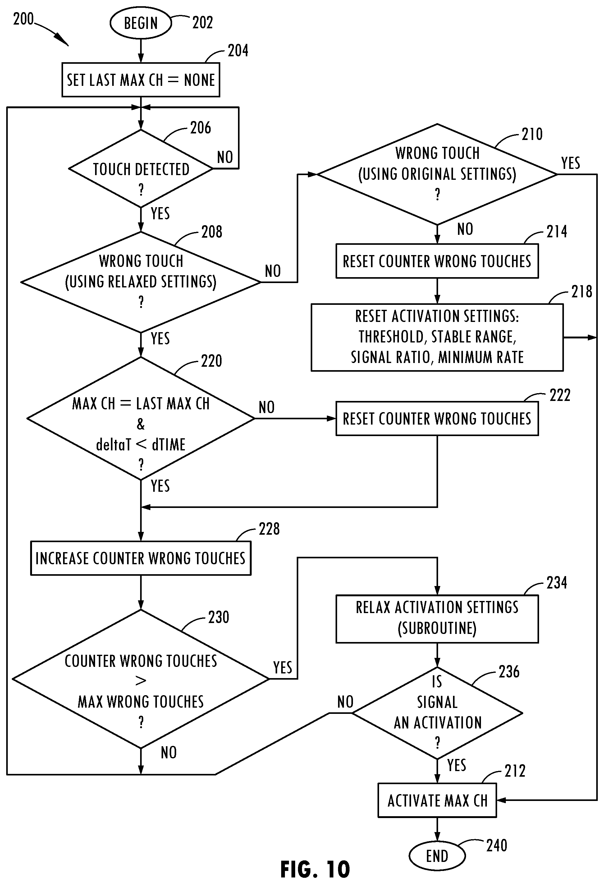
The proximity switch assembly 20 employs an adaptive learning routine 200 which may be stored within memory 28 of controller 24 and executed by microprocessor 26, according to one embodiment. The adaptive learning routine 200 detects the wrong touch conditions based on multiple attempted activations of a proximity switch that is not allowed and adjusts one or more settings to provide for adaptive learning to allow activation of the proximity switch in situations where insufficient activations of a switch that a user is attempting to activate are repeatedly attempted. The adaptive learning routine 200 is illustrated in FIG. 10, according to one embodiment. Routine 200 begins at step 202 and proceeds to step 204 to set the last maximum signal channel equal to none so as to reset the value. Next, at decision step 206, routine 200 determines if a user touch of the proximity assembly has been detected and, if not, waits for the detection of a user touch. Once a user touch has been detected, routine 200 proceeds to decision step 208 to determine whether a wrong touch condition has occurred while using relaxed settings or parameters. If no such wrong touch condition has occurred, routine 200 proceeds to decision step 210 to determine whether a wrong touch condition occurred using the original (e.g., default) settings and, if so, proceeds to step 212 to activate the proximity switch associated with the maximum signal channel before ending at step 240.
If a wrong touch condition using the original settings is not detected at step 210, routine 200 proceeds to step 214 to reset the counter labelled wrong touches. The wrong touches counter indicates the number of repeated wrong touch conditions that are detected for a switch. Next, at step 218, the activation settings are reset which may include one or more of a threshold, stable range, a signal ratio and a minimum rate, according to various embodiments. Routine 200 then proceeds to step 212 to activate the proximity switch associated with the maximum signal channel before ending at step 240.
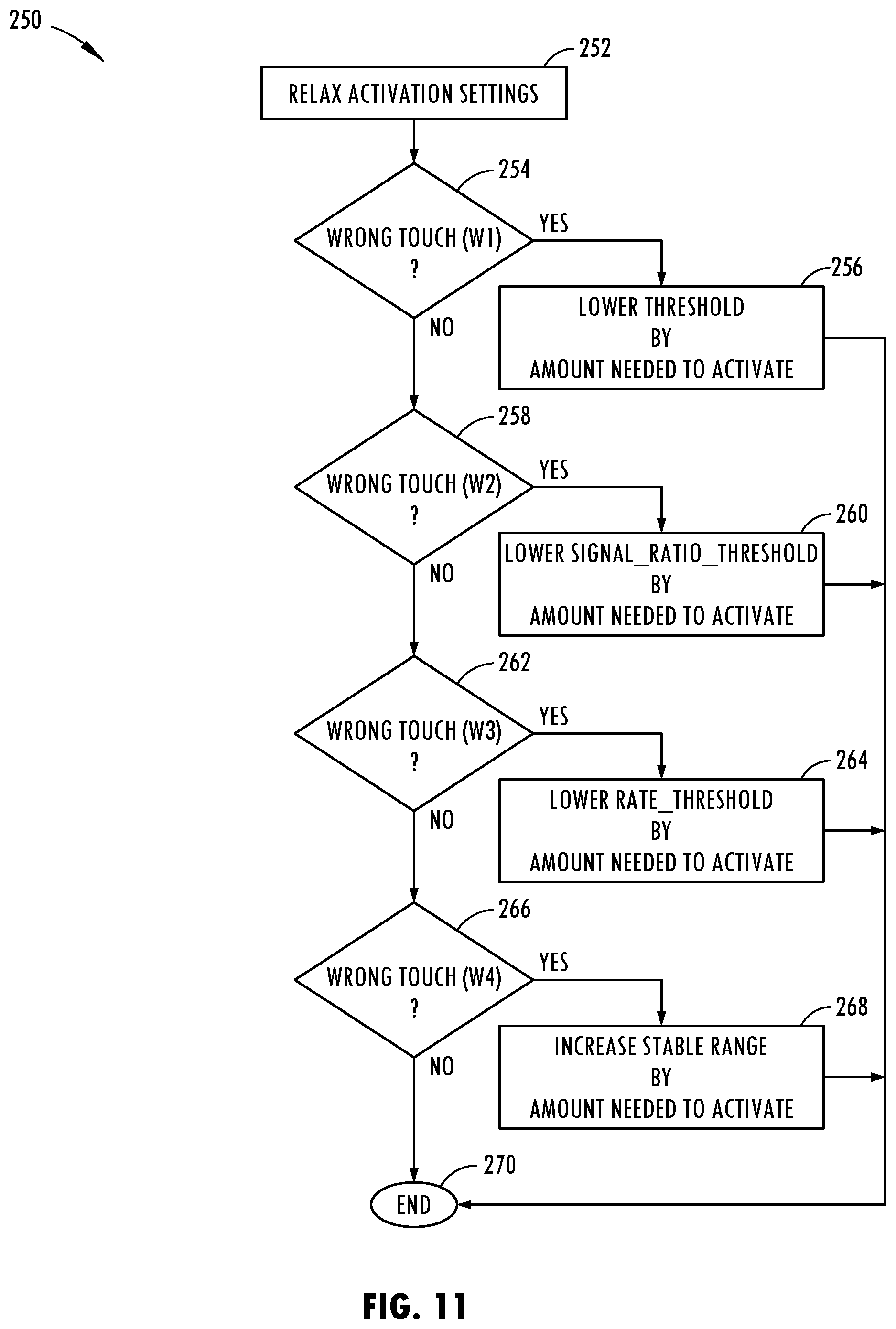
Returning to decision block 208, if a wrong touch condition using relaxed settings is detected, routine 200 proceeds to decision step 220 to determine if the maximum signal channel is equal to the last maximum signal channel and if the deltaT time is less than dTIME. The deltaT time is the time since the first attempted activation, and the dTIME time is a time period, such as five (5) seconds, or more preferably in the range of two to four (2-4) seconds. If the conditions at step 220 are not met, routine 200 proceeds to step 222 to reset the counter wrong touches before proceeding to step 228. If the conditions in step 220 are met, routine 200 proceeds directly to step 228 to increase the counter wrong touches value. Thereafter, at decision step 230, routine 200 determines if the counter wrong touches value is greater than the maximum wrong touches value. The maximum wrong touches value may be a value of one or more, and more preferably two or more and is used to determine repeated attempted activations of a switch that is not allowed. If the counter wrong touches value is not greater than the maximum wrong touches, then routine 200 returns to step 206. If the counter wrong touches value is greater than the maximum wrong touches value, routine 200 proceeds to step 234 to relax the activation settings to thereby adjust one or more settings associated with the determining of an activation of the proximity switch. IN one example, the setting(s) are adjusted when three attempted activations occur in a time period of two to four (2-4) seconds. Following execution of the relaxed activation settings subroutine, routine 200 proceeds to decision step 236 to determine if the maximum signal associated with proximity switch is an activation and, if so, proceeds to step 212 to activate the proximity switch associated with the maximum signal channel before ending at step 240. If the signal is not an activation, routine 200 returns to step 206.
The relaxed activation settings subroutine 250 is illustrated in FIG. 11, according to one embodiment. Subroutine 250 begins at step 252 and proceeds to decision step 254 to determine if a wrong touch condition W1 exists. The wrong touch W1 condition may be a maximum signal that is below a threshold such as a signal resulting from a finger having poor conductive properties due to lotion on the finger or a glove covering the finger. If the wrong touch W1 condition is detected, subroutine 250 proceeds to step 256 to lower the activation threshold by an amount needed to activate the switch, before ending at step 270. If wrong touch W1 condition is not detected, subroutine 250 proceeds to decision step 258 to determine if wrong touch W2 condition is detected. Wrong touch W2 condition may be the condition where a signal ratio such as a maximum signal versus the other signal channels is too low, which may occur when two or more switches are attempted to be activated simultaneously. If a wrong touch W2 condition is detected, subroutine 250 proceeds to step 260 to lower the signal ratio threshold by an amount needed to activate the switch and thereafter ends at step 270. If wrong touch W2 condition is not detected, subroutine 250 proceeds to decision step 262 to determine if a wrong touch W3 condition is detected. The wrong touch W3 condition may occur when the rate of the signal increases too slow, which may occur when a finger slowly approaches the proximity sensor assembly, particularly when a glove is worn on the user's finger. If a wrong touch W3 condition is detected, subroutine 250 proceeds to step 264 to lower the signal rate threshold by an amount needed to activate the proximity switch, before ending at step 270. If wrong touch W3 condition is not detected, subroutine 250 proceeds to decision step 266 to determine if a wrong touch W4 condition is detected. The wrong touch W4 condition may occur when the signal is unstable, which may occur when a person's finger is shaking or there is excess noise in the signal. If a wrong touch W4 condition is detected, subroutine 250 proceeds to step 268 to increase the stable range by an amount needed to activate the switch before ending at step 270. Accordingly, subroutine 250 determines one or more wrong touch conditions such as conditions W1, W2, W3 and W4 and adjusts one or more settings based on the attempted activation so as to provide adaptive learning to allow activation of the proximity switch following repeated attempts by a user.
Accordingly, the proximity switch arrangement 20 advantageously provides for enhanced user interaction and user perceived feedback to a user to indicate whether the proximity switches have been properly activated to perform an action that is available. The switch assembly 20 allows users to be trained on use of the switch arrangement with feedback. Additionally, the switch arrangement may be less distractive by providing the user with perceived feedback, which is particularly advantageous in automotive applications. The switch assembly 20 further provides adaptive learning by adjusting one or more settings when a repeated multiple wrong touch condition is detected to allow activation of a proximity switch and thus, adapts to the user's interface signature.
It is to be understood that variations and modifications can be made on the aforementioned structure without departing from the concepts of the present invention, and further it is to be understood that such concepts are intended to be covered by the following claims unless these claims by their language expressly state otherwise.
* * * * *
References
D00000
D00001
D00002
D00003
D00004
D00005
D00006
D00007
XML
uspto.report is an independent third-party trademark research tool that is not affiliated, endorsed, or sponsored by the United States Patent and Trademark Office (USPTO) or any other governmental organization. The information provided by uspto.report is based on publicly available data at the time of writing and is intended for informational purposes only.
While we strive to provide accurate and up-to-date information, we do not guarantee the accuracy, completeness, reliability, or suitability of the information displayed on this site. The use of this site is at your own risk. Any reliance you place on such information is therefore strictly at your own risk.
All official trademark data, including owner information, should be verified by visiting the official USPTO website at www.uspto.gov. This site is not intended to replace professional legal advice and should not be used as a substitute for consulting with a legal professional who is knowledgeable about trademark law.