Surgical stapling loading unit
Cai , et al. Dec
U.S. patent number 10,499,916 [Application Number 15/531,783] was granted by the patent office on 2019-12-10 for surgical stapling loading unit. This patent grant is currently assigned to Covidien LP. The grantee listed for this patent is Covidien LP. Invention is credited to Longsheng Cai, Zhaokai Wang, Xiliang Zhang.


View All Diagrams
| United States Patent | 10,499,916 |
| Cai , et al. | December 10, 2019 |
Surgical stapling loading unit
Abstract
A surgical loading unit (10) for use with a surgical handle assembly (1000) includes a handle mount (12) dimensioned for mounting to the handle assembly (1000), an outer member (56) extending from the handle mount (12), a staple cartridge assembly (16) mounted to the distal end of the outer member (56), and an anvil assembly (18) couplable relative to the staple cartridge assembly (16). A staple pusher (60) is at least partially disposed within the outer member (56) and operatively coupled to the staple cartridge assembly (16). The staple pusher (60) is adapted for longitudinal movement to eject staples from the staple cartridge assembly (16). An anvil approximator (94) is at least partially disposed within the outer member (56) and is operatively coupled to the anvil assembly (18). The anvil approximator (94) is adapted for movement between first and second positions corresponding to closed and open conditions of the anvil assembly (18) relative to the staple cartridge assembly (16). A lock member (24) is mounted to the handle mount (12). The lock member (12) is adapted to move from a lock position in secured engagement with the staple pusher (60) and the anvil approximator (94) to a release position releasing the staple pusher (60) and the anvil approximator (94) upon mounting of the handle mount (12) relative to the surgical handle assembly (1000).
| Inventors: | Cai; Longsheng (Shanghai, CN), Zhang; Xiliang (Shanghai, CN), Wang; Zhaokai (Shanghai, CN) | ||||||||||
|---|---|---|---|---|---|---|---|---|---|---|---|
| Applicant: |
|
||||||||||
| Assignee: | Covidien LP (Mansfield,
MA) |
||||||||||
| Family ID: | 56106463 | ||||||||||
| Appl. No.: | 15/531,783 | ||||||||||
| Filed: | December 11, 2014 | ||||||||||
| PCT Filed: | December 11, 2014 | ||||||||||
| PCT No.: | PCT/CN2014/093563 | ||||||||||
| 371(c)(1),(2),(4) Date: | May 31, 2017 | ||||||||||
| PCT Pub. No.: | WO2016/090594 | ||||||||||
| PCT Pub. Date: | June 16, 2016 |
Prior Publication Data
| Document Identifier | Publication Date | |
|---|---|---|
| US 20170340326 A1 | Nov 30, 2017 | |
| Current U.S. Class: | 1/1 |
| Current CPC Class: | A61B 17/00234 (20130101); A61B 17/07207 (20130101); A61B 17/1155 (20130101); A61B 17/064 (20130101); A61B 17/068 (20130101); A61B 2017/00477 (20130101); A61B 17/072 (20130101); A61B 2017/07271 (20130101); A61B 2017/0725 (20130101); A61B 2017/0046 (20130101); A61B 2017/07257 (20130101) |
| Current International Class: | A61B 17/072 (20060101); A61B 17/115 (20060101); A61B 17/064 (20060101); A61B 17/00 (20060101); A61B 17/068 (20060101) |
| Field of Search: | ;227/19,175.2,175.3,176.1,180.1 ;606/139,153,213,219 |
References Cited [Referenced By]
U.S. Patent Documents
| 3193165 | July 1965 | Akhalaya et al. |
| 3388847 | June 1968 | Kasulin et al. |
| 3552626 | January 1971 | Astafiev et al. |
| 3638652 | February 1972 | Kelley |
| 3771526 | November 1973 | Rudie |
| 4198982 | April 1980 | Fortner et al. |
| 4207898 | June 1980 | Becht |
| 4289133 | September 1981 | Rothfuss |
| 4304236 | December 1981 | Conta et al. |
| 4319576 | March 1982 | Rothfuss |
| 4350160 | September 1982 | Kolesov et al. |
| 4351466 | September 1982 | Noiles |
| 4379457 | April 1983 | Gravener et al. |
| 4473077 | September 1984 | Noiles et al. |
| 4476863 | October 1984 | Kanshin et al. |
| 4485817 | December 1984 | Swiggett |
| 4488523 | December 1984 | Shichman |
| 4505272 | March 1985 | Utyamyshev et al. |
| 4505414 | March 1985 | Filipi |
| 4520817 | June 1985 | Green |
| 4550870 | November 1985 | Krumme et al. |
| 4573468 | March 1986 | Conta et al. |
| 4576167 | March 1986 | Noiles |
| 4592354 | June 1986 | Rothfuss |
| 4603693 | August 1986 | Conta et al. |
| 4606343 | August 1986 | Conta et al. |
| 4632290 | December 1986 | Green et al. |
| 4646745 | March 1987 | Noiles |
| 4665917 | May 1987 | Clanton et al. |
| 4667673 | May 1987 | Li |
| 4671445 | June 1987 | Barker et al. |
| 4700703 | October 1987 | Resnick et al. |
| 4703887 | November 1987 | Clanton et al. |
| 4708141 | November 1987 | Inoue et al. |
| 4717063 | January 1988 | Ebihara |
| 4752024 | June 1988 | Green et al. |
| 4754909 | July 1988 | Barker et al. |
| 4776506 | October 1988 | Green |
| 4817847 | April 1989 | Redtenbacher et al. |
| 4873977 | October 1989 | Avant et al. |
| 4893662 | January 1990 | Gervasi |
| 4903697 | February 1990 | Resnick et al. |
| 4907591 | March 1990 | Vasconcellos et al. |
| 4917114 | April 1990 | Green et al. |
| 4957499 | September 1990 | Lipatov et al. |
| 4962877 | October 1990 | Hervas |
| 5005749 | April 1991 | Aranyi |
| 5042707 | August 1991 | Taheri |
| 5047039 | September 1991 | Avant et al. |
| 5104025 | April 1992 | Main et al. |
| 5119983 | June 1992 | Green et al. |
| 5122156 | June 1992 | Granger et al. |
| 5139513 | August 1992 | Segato |
| 5158222 | October 1992 | Green et al. |
| 5188638 | February 1993 | Tzakis |
| 5193731 | March 1993 | Aranyi |
| 5197648 | March 1993 | Gingold |
| 5197649 | March 1993 | Bessler et al. |
| 5205459 | April 1993 | Brinkerhoff et al. |
| 5221036 | June 1993 | Takase |
| 5222963 | June 1993 | Brinkerhoff et al. |
| 5253793 | October 1993 | Green et al. |
| 5261920 | November 1993 | Main et al. |
| 5271543 | December 1993 | Grant et al. |
| 5271544 | December 1993 | Fox et al. |
| 5275322 | January 1994 | Brinkerhoff et al. |
| 5282810 | February 1994 | Allen et al. |
| 5285944 | February 1994 | Green et al. |
| 5285945 | February 1994 | Brinkerhoff et al. |
| 5292053 | March 1994 | Bilotti et al. |
| 5309927 | May 1994 | Welch |
| 5312024 | May 1994 | Grant et al. |
| 5314435 | May 1994 | Green et al. |
| 5314436 | May 1994 | Wilk |
| 5330486 | July 1994 | Wilk |
| 5333773 | August 1994 | Main et al. |
| 5344059 | September 1994 | Green et al. |
| 5346115 | September 1994 | Perouse et al. |
| 5348259 | September 1994 | Blanco et al. |
| 5350104 | September 1994 | Main et al. |
| 5355897 | October 1994 | Pietrafitta et al. |
| 5360154 | November 1994 | Green |
| 5368215 | November 1994 | Green et al. |
| 5392979 | February 1995 | Green et al. |
| 5395030 | March 1995 | Kuramoto et al. |
| 5403333 | April 1995 | Kaster et al. |
| 5404870 | April 1995 | Brinkerhoff et al. |
| 5411508 | May 1995 | Bessler et al. |
| 5425738 | June 1995 | Gustafson et al. |
| 5433721 | July 1995 | Hooven et al. |
| 5437684 | August 1995 | Calabrese et al. |
| 5439156 | August 1995 | Grant et al. |
| 5443198 | August 1995 | Viola et al. |
| 5447514 | September 1995 | Gerry et al. |
| 5454825 | October 1995 | Van Leeuwen et al. |
| 5464415 | November 1995 | Chen |
| 5470006 | November 1995 | Rodak |
| 5474223 | December 1995 | Viola et al. |
| 5497934 | March 1996 | Brady et al. |
| 5503635 | April 1996 | Sauer et al. |
| 5522534 | June 1996 | Viola et al. |
| 5533661 | July 1996 | Main et al. |
| 5588579 | December 1996 | Schnut et al. |
| 5609285 | March 1997 | Grant et al. |
| 5626591 | May 1997 | Kockerling et al. |
| 5632433 | May 1997 | Grant et al. |
| 5639008 | June 1997 | Gallagher et al. |
| 5641111 | June 1997 | Ahrens et al. |
| 5658300 | August 1997 | Bito et al. |
| 5669918 | September 1997 | Balazs et al. |
| 5685474 | November 1997 | Seeber |
| 5709335 | January 1998 | Heck |
| 5715987 | February 1998 | Kelley et al. |
| 5718360 | February 1998 | Green et al. |
| 5720755 | February 1998 | Dakov |
| 5732872 | March 1998 | Bolduc et al. |
| 5749896 | May 1998 | Cook |
| 5758814 | June 1998 | Gallagher et al. |
| 5799857 | September 1998 | Robertson et al. |
| 5814055 | September 1998 | Knodel et al. |
| 5833698 | November 1998 | Hinchliffe et al. |
| 5836503 | November 1998 | Ehrenfels et al. |
| 5839639 | November 1998 | Sauer et al. |
| 5855312 | January 1999 | Toledano |
| 5860581 | January 1999 | Robertson et al. |
| 5868760 | February 1999 | McGuckin, Jr. |
| 5881943 | March 1999 | Heck et al. |
| 5915616 | June 1999 | Viola et al. |
| 5947363 | September 1999 | Bolduc et al. |
| 5951576 | September 1999 | Wakabayashi |
| 5957363 | September 1999 | Heck |
| 5993468 | November 1999 | Rygaard |
| 6024748 | February 2000 | Manzo et al. |
| 6050472 | April 2000 | Shibata |
| 6053390 | April 2000 | Green et al. |
| 6068636 | May 2000 | Chen |
| 6083241 | July 2000 | Longo et al. |
| 6102271 | August 2000 | Longo et al. |
| 6117148 | September 2000 | Ravo et al. |
| 6119913 | September 2000 | Adams et al. |
| 6126058 | October 2000 | Adams et al. |
| 6142933 | November 2000 | Longo et al. |
| 6149667 | November 2000 | Hovland et al. |
| 6176413 | January 2001 | Heck et al. |
| 6179195 | January 2001 | Adams et al. |
| 6193129 | February 2001 | Bittner et al. |
| 6203553 | March 2001 | Robertson et al. |
| 6209773 | April 2001 | Bolduc et al. |
| 6241140 | June 2001 | Adams et al. |
| 6253984 | July 2001 | Heck et al. |
| 6258107 | July 2001 | Balazs et al. |
| 6264086 | July 2001 | McGuckin, Jr. |
| 6269997 | August 2001 | Balazs et al. |
| 6273897 | August 2001 | Dalessandro et al. |
| 6279809 | August 2001 | Nicolo |
| 6302311 | October 2001 | Adams et al. |
| 6338737 | January 2002 | Toledano |
| 6343731 | February 2002 | Adams et al. |
| 6387105 | May 2002 | Gifford, III et al. |
| 6398795 | June 2002 | McAlister et al. |
| 6402008 | June 2002 | Lucas |
| 6439446 | August 2002 | Perry et al. |
| 6443973 | September 2002 | Whitman |
| 6450390 | September 2002 | Heck et al. |
| 6478210 | November 2002 | Adams et al. |
| 6488197 | December 2002 | Whitman |
| 6491201 | December 2002 | Whitman |
| 6494877 | December 2002 | Odell et al. |
| 6503259 | January 2003 | Huxel et al. |
| 6517566 | February 2003 | Hovland et al. |
| 6520398 | February 2003 | Nicolo |
| 6533157 | March 2003 | Whitman |
| 6551334 | April 2003 | Blatter et al. |
| 6578751 | June 2003 | Hartwick |
| 6585144 | July 2003 | Adams et al. |
| 6588643 | July 2003 | Bolduc et al. |
| 6592596 | July 2003 | Geitz |
| 6601749 | August 2003 | Sullivan et al. |
| 6605078 | August 2003 | Adams |
| 6605098 | August 2003 | Nobis et al. |
| 6626921 | September 2003 | Blatter et al. |
| 6629630 | October 2003 | Adams |
| 6631837 | October 2003 | Heck |
| 6632227 | October 2003 | Adams |
| 6632237 | October 2003 | Ben-David et al. |
| 6652542 | November 2003 | Blatter et al. |
| 6659327 | December 2003 | Heck et al. |
| 6676671 | January 2004 | Robertson et al. |
| 6681979 | January 2004 | Whitman |
| 6685079 | February 2004 | Sharma et al. |
| 6695198 | February 2004 | Adams et al. |
| 6695199 | February 2004 | Whitman |
| 6698643 | March 2004 | Whitman |
| 6716222 | April 2004 | McAlister et al. |
| 6716233 | April 2004 | Whitman |
| 6726697 | April 2004 | Nicholas et al. |
| 6742692 | June 2004 | Hartwick |
| 6743244 | June 2004 | Blatter et al. |
| 6763993 | July 2004 | Bolduc et al. |
| 6769590 | August 2004 | Vresh et al. |
| 6769594 | August 2004 | Orban, III |
| 6820791 | November 2004 | Adams |
| 6821282 | November 2004 | Perry et al. |
| 6827246 | December 2004 | Sullivan et al. |
| 6840423 | January 2005 | Adams et al. |
| 6843403 | January 2005 | Whitman |
| 6846308 | January 2005 | Whitman et al. |
| 6852122 | February 2005 | Rush |
| 6866178 | March 2005 | Adams et al. |
| 6872214 | March 2005 | Sonnenschein et al. |
| 6874669 | April 2005 | Adams et al. |
| 6884250 | April 2005 | Monassevitch et al. |
| 6905504 | June 2005 | Vargas |
| 6938814 | September 2005 | Sharma et al. |
| 6942675 | September 2005 | Vargas |
| 6945444 | September 2005 | Gresham et al. |
| 6953138 | October 2005 | Dworak et al. |
| 6957758 | October 2005 | Aranyi |
| 6959851 | November 2005 | Heinrich |
| 6978922 | December 2005 | Bilotti et al. |
| 6981941 | January 2006 | Whitman et al. |
| 6981979 | January 2006 | Nicolo |
| 7032798 | April 2006 | Whitman et al. |
| 7059331 | June 2006 | Adams et al. |
| 7059510 | June 2006 | Orban, III |
| 7077856 | July 2006 | Whitman |
| 7080769 | July 2006 | Vresh et al. |
| 7086267 | August 2006 | Dworak et al. |
| 7114642 | October 2006 | Whitman |
| 7118528 | October 2006 | Piskun |
| 7122044 | October 2006 | Bolduc et al. |
| 7128748 | October 2006 | Mooradian et al. |
| 7141055 | November 2006 | Abrams et al. |
| 7168604 | January 2007 | Milliman et al. |
| 7179267 | February 2007 | Nolan et al. |
| 7182239 | February 2007 | Myers |
| 7195142 | March 2007 | Orban, III |
| 7207168 | April 2007 | Doepker et al. |
| 7220237 | May 2007 | Gannoe et al. |
| 7234624 | June 2007 | Gresham et al. |
| 7235089 | June 2007 | McGuckin, Jr. |
| RE39841 | September 2007 | Bilotti et al. |
| 7285125 | October 2007 | Viola |
| 7303106 | December 2007 | Milliman et al. |
| 7303107 | December 2007 | Milliman et al. |
| 7309341 | December 2007 | Ortiz et al. |
| 7322994 | January 2008 | Nicholas et al. |
| 7325713 | February 2008 | Aranyi |
| 7334718 | February 2008 | McAlister et al. |
| 7335212 | February 2008 | Edoga et al. |
| 7364060 | April 2008 | Milliman |
| 7398908 | July 2008 | Holsten et al. |
| 7399305 | July 2008 | Csiky et al. |
| 7401721 | July 2008 | Holsten et al. |
| 7401722 | July 2008 | Hur |
| 7407075 | August 2008 | Holsten et al. |
| 7410086 | August 2008 | Ortiz et al. |
| 7422137 | September 2008 | Manzo |
| 7422138 | September 2008 | Bilotti et al. |
| 7431191 | October 2008 | Milliman |
| 7438718 | October 2008 | Milliman et al. |
| 7455676 | November 2008 | Holsten et al. |
| 7455682 | November 2008 | Viola |
| 7481347 | January 2009 | Roy |
| 7494038 | February 2009 | Milliman |
| 7506791 | March 2009 | Omaits et al. |
| 7516877 | April 2009 | Aranyi |
| 7527185 | May 2009 | Harari et al. |
| 7537602 | May 2009 | Whitman |
| 7540839 | June 2009 | Butler et al. |
| 7546939 | June 2009 | Adams et al. |
| 7546940 | June 2009 | Milliman et al. |
| 7547312 | June 2009 | Bauman et al. |
| 7556186 | July 2009 | Milliman |
| 7559451 | July 2009 | Sharma et al. |
| 7585306 | September 2009 | Abbott et al. |
| 7588174 | September 2009 | Holsten et al. |
| 7600663 | October 2009 | Green |
| 7611038 | November 2009 | Racenet et al. |
| 7635385 | December 2009 | Milliman et al. |
| 7669747 | March 2010 | Weisenburgh, II et al. |
| 7686201 | March 2010 | Csiky |
| 7694864 | April 2010 | Okada et al. |
| 7699204 | April 2010 | Viola |
| 7708181 | May 2010 | Cole et al. |
| 7717313 | May 2010 | Criscuolo et al. |
| 7721932 | May 2010 | Cole et al. |
| 7726539 | June 2010 | Holsten et al. |
| 7743958 | June 2010 | Orban, III |
| 7744627 | June 2010 | Orban, III et al. |
| 7770776 | August 2010 | Chen et al. |
| 7771440 | August 2010 | Ortiz et al. |
| 7776060 | August 2010 | Mooradian et al. |
| 7793813 | September 2010 | Bettuchi |
| 7802712 | September 2010 | Milliman et al. |
| 7823592 | November 2010 | Bettuchi et al. |
| 7837079 | November 2010 | Holsten et al. |
| 7837080 | November 2010 | Schwemberger |
| 7837081 | November 2010 | Holsten et al. |
| 7845536 | December 2010 | Viola et al. |
| 7845538 | December 2010 | Whitman |
| 7857187 | December 2010 | Milliman |
| 7886951 | February 2011 | Hessler |
| 7896215 | March 2011 | Adams et al. |
| 7900806 | March 2011 | Chen et al. |
| 7909039 | March 2011 | Hur |
| 7909219 | March 2011 | Cole et al. |
| 7909222 | March 2011 | Cole et al. |
| 7909223 | March 2011 | Cole et al. |
| 7913892 | March 2011 | Cole et al. |
| 7918377 | April 2011 | Measamer et al. |
| 7922062 | April 2011 | Cole et al. |
| 7922743 | April 2011 | Heinrich et al. |
| 7931183 | April 2011 | Orban, III |
| 7938307 | May 2011 | Bettuchi |
| 7942302 | May 2011 | Roby et al. |
| 7951166 | May 2011 | Orban, III et al. |
| 7959050 | June 2011 | Smith et al. |
| 7967181 | June 2011 | Viola et al. |
| 7975895 | July 2011 | Milliman |
| 8002795 | August 2011 | Beetel |
| 8006701 | August 2011 | Bilotti et al. |
| 8006889 | August 2011 | Adams et al. |
| 8011551 | September 2011 | Marczyk et al. |
| 8011554 | September 2011 | Milliman |
| 8016177 | September 2011 | Bettuchi et al. |
| 8016858 | September 2011 | Whitman |
| 8020741 | September 2011 | Cole et al. |
| 8025199 | September 2011 | Whitman et al. |
| 8028885 | October 2011 | Smith et al. |
| 8038046 | October 2011 | Smith et al. |
| 8043207 | October 2011 | Adams |
| 8066167 | November 2011 | Measamer et al. |
| 8066169 | November 2011 | Viola |
| 8070035 | December 2011 | Holsten et al. |
| 8070037 | December 2011 | Csiky |
| 8096458 | January 2012 | Hessler |
| 8109426 | February 2012 | Milliman et al. |
| 8109427 | February 2012 | Orban, III |
| 8113406 | February 2012 | Holsten et al. |
| 8113407 | February 2012 | Holsten et al. |
| 8123103 | February 2012 | Milliman |
| 8128645 | March 2012 | Sonnenschein et al. |
| 8132703 | March 2012 | Milliman et al. |
| 8136712 | March 2012 | Zingman |
| 8146790 | April 2012 | Milliman |
| 8146791 | April 2012 | Bettuchi et al. |
| 8181838 | May 2012 | Milliman et al. |
| 8192460 | June 2012 | Orban, III et al. |
| 8201720 | June 2012 | Hessler |
| 8203782 | June 2012 | Brueck et al. |
| 8211130 | July 2012 | Viola |
| 8225799 | July 2012 | Bettuchi |
| 8225981 | July 2012 | Criscuolo et al. |
| 8231041 | July 2012 | Marczyk et al. |
| 8231042 | July 2012 | Hessler et al. |
| 8257391 | September 2012 | Orban, III et al. |
| 8267301 | September 2012 | Milliman et al. |
| 8272552 | September 2012 | Holsten et al. |
| 8276802 | October 2012 | Kostrzewski |
| 8281975 | October 2012 | Criscuolo et al. |
| 8286845 | October 2012 | Perry et al. |
| 8308045 | November 2012 | Bettuchi et al. |
| 8312885 | November 2012 | Bettuchi et al. |
| 8313014 | November 2012 | Bettuchi |
| 8317073 | November 2012 | Milliman et al. |
| 8317074 | November 2012 | Ortiz et al. |
| 8322590 | December 2012 | Patel et al. |
| 8328060 | December 2012 | Jankowski et al. |
| 8328062 | December 2012 | Viola |
| 8328063 | December 2012 | Milliman et al. |
| 8343185 | January 2013 | Milliman et al. |
| 8353438 | January 2013 | Baxter, III et al. |
| 8353439 | January 2013 | Baxter, III et al. |
| 8353930 | January 2013 | Heinrich et al. |
| 8360295 | January 2013 | Milliman et al. |
| 8365974 | February 2013 | Milliman |
| 8403942 | March 2013 | Milliman et al. |
| 8408441 | April 2013 | Wenchell et al. |
| 8413870 | April 2013 | Pastorelli et al. |
| 8413872 | April 2013 | Patel |
| 8418905 | April 2013 | Milliman |
| 8418909 | April 2013 | Kostrzewski |
| 8424535 | April 2013 | Hessler et al. |
| 8424741 | April 2013 | McGuckin, Jr. et al. |
| 8430291 | April 2013 | Heinrich et al. |
| 8430292 | April 2013 | Patel et al. |
| 8453910 | June 2013 | Bettuchi et al. |
| 8453911 | June 2013 | Milliman et al. |
| 8485414 | July 2013 | Criscuolo et al. |
| 8490853 | July 2013 | Criscuolo et al. |
| 8511533 | August 2013 | Viola et al. |
| 8551138 | October 2013 | Orban, III et al. |
| 8567655 | October 2013 | Nalagatla et al. |
| 8579178 | November 2013 | Holsten et al. |
| 8590763 | November 2013 | Milliman |
| 8590764 | November 2013 | Hartwick et al. |
| 8608047 | December 2013 | Holsten et al. |
| 8616428 | December 2013 | Milliman et al. |
| 8616429 | December 2013 | Viola |
| 8622275 | January 2014 | Baxter, III et al. |
| 8631993 | January 2014 | Kostrzewski |
| 8636187 | January 2014 | Hueil et al. |
| 8640940 | February 2014 | Ohdaira |
| 8662370 | March 2014 | Takei |
| 8663258 | March 2014 | Bettuchi et al. |
| 8672931 | March 2014 | Goldboss et al. |
| 8678264 | March 2014 | Racenet et al. |
| 8684248 | April 2014 | Milliman |
| 8684250 | April 2014 | Bettuchi et al. |
| 8684251 | April 2014 | Rebuffat et al. |
| 8684252 | April 2014 | Patel et al. |
| 8733611 | May 2014 | Milliman |
| 8939343 | January 2015 | Milliman |
| 9566064 | February 2017 | Williams |
| 9757126 | September 2017 | Cappola |
| 9918717 | March 2018 | Czernik |
| 10045782 | August 2018 | Murthy Aravalli |
| 10085750 | October 2018 | Zergiebel |
| 10285698 | May 2019 | Cappola |
| 2003/0111507 | June 2003 | Nunez |
| 2004/0073090 | April 2004 | Butler et al. |
| 2005/0051597 | March 2005 | Toledano |
| 2005/0107813 | May 2005 | Gilete Garcia |
| 2006/0000869 | January 2006 | Fontayne |
| 2006/0011698 | January 2006 | Okada et al. |
| 2006/0201989 | September 2006 | Ojeda |
| 2007/0027473 | February 2007 | Vresh et al. |
| 2007/0029363 | February 2007 | Popov |
| 2007/0060952 | March 2007 | Roby et al. |
| 2009/0099566 | April 2009 | Maness et al. |
| 2009/0236392 | September 2009 | Cole et al. |
| 2009/0236398 | September 2009 | Cole et al. |
| 2009/0236401 | September 2009 | Cole et al. |
| 2010/0019016 | January 2010 | Edoga et al. |
| 2010/0051668 | March 2010 | Milliman et al. |
| 2010/0084453 | April 2010 | Hu |
| 2010/0147923 | June 2010 | D'Agostino et al. |
| 2010/0163598 | July 2010 | Belzer |
| 2010/0224668 | September 2010 | Fontayne et al. |
| 2010/0230465 | September 2010 | Smith et al. |
| 2010/0258611 | October 2010 | Smith et al. |
| 2010/0264195 | October 2010 | Bettuchi |
| 2010/0301097 | December 2010 | Scirica |
| 2010/0327041 | December 2010 | Milliman et al. |
| 2011/0011916 | January 2011 | Levine |
| 2011/0114697 | May 2011 | Baxter, III et al. |
| 2011/0114700 | May 2011 | Baxter, III et al. |
| 2011/0144640 | June 2011 | Heinrich et al. |
| 2011/0147432 | June 2011 | Heinrich et al. |
| 2011/0192882 | August 2011 | Hess et al. |
| 2012/0145755 | June 2012 | Kahn |
| 2012/0193395 | August 2012 | Pastorelli et al. |
| 2012/0193398 | August 2012 | Williams et al. |
| 2012/0232339 | September 2012 | Csiky |
| 2012/0273548 | November 2012 | Ma et al. |
| 2012/0305627 | December 2012 | Milliman et al. |
| 2012/0325888 | December 2012 | Qiao et al. |
| 2013/0015232 | January 2013 | Smith et al. |
| 2013/0020372 | January 2013 | Jankowski et al. |
| 2013/0020373 | January 2013 | Smith et al. |
| 2013/0032628 | February 2013 | Li et al. |
| 2013/0056516 | March 2013 | Viola |
| 2013/0060258 | March 2013 | Giacomantonio |
| 2013/0105544 | May 2013 | Mozdzierz et al. |
| 2013/0105546 | May 2013 | Milliman et al. |
| 2013/0105551 | May 2013 | Zingman |
| 2013/0126580 | May 2013 | Smith et al. |
| 2013/0153630 | June 2013 | Miller et al. |
| 2013/0153631 | June 2013 | Vasudevan et al. |
| 2013/0153633 | June 2013 | Casasanta, Jr. et al. |
| 2013/0153634 | June 2013 | Carter et al. |
| 2013/0153638 | June 2013 | Carter et al. |
| 2013/0153639 | June 2013 | Hodgkinson et al. |
| 2013/0175315 | July 2013 | Milliman |
| 2013/0175318 | July 2013 | Felder et al. |
| 2013/0175319 | July 2013 | Felder et al. |
| 2013/0175320 | July 2013 | Mandakolathur Vasudevan et al. |
| 2013/0181035 | July 2013 | Milliman |
| 2013/0181036 | July 2013 | Olson et al. |
| 2013/0186930 | July 2013 | Wenchell et al. |
| 2013/0193185 | August 2013 | Patel |
| 2013/0193187 | August 2013 | Milliman |
| 2013/0193190 | August 2013 | Carter et al. |
| 2013/0193191 | August 2013 | Stevenson et al. |
| 2013/0193192 | August 2013 | Casasanta, Jr. et al. |
| 2013/0200131 | August 2013 | Racenet et al. |
| 2013/0206816 | August 2013 | Penna |
| 2013/0214027 | August 2013 | Hessler et al. |
| 2013/0214028 | August 2013 | Patel et al. |
| 2013/0228609 | September 2013 | Kostrzewski |
| 2013/0240597 | September 2013 | Milliman et al. |
| 2013/0240600 | September 2013 | Bettuchi |
| 2013/0248581 | September 2013 | Smith et al. |
| 2013/0277411 | October 2013 | Hodgkinson et al. |
| 2013/0277412 | October 2013 | Gresham et al. |
| 2013/0284792 | October 2013 | Ma |
| 2013/0292449 | November 2013 | Bettuchi et al. |
| 2013/0299553 | November 2013 | Mozdzierz |
| 2013/0299554 | November 2013 | Mozdzierz |
| 2013/0306701 | November 2013 | Olson |
| 2013/0306707 | November 2013 | Viola et al. |
| 2014/0008413 | January 2014 | Williams |
| 2014/0012317 | January 2014 | Orban et al. |
| 2017/0027575 | February 2017 | Murthy Aravalli |
| 908529 | Aug 1972 | CA | |||
| 2805365 | Aug 2013 | CA | |||
| 101843509 | Sep 2010 | CN | |||
| 1057729 | May 1959 | DE | |||
| 3301713 | Jul 1984 | DE | |||
| 0152382 | Aug 1985 | EP | |||
| 0173451 | Mar 1986 | EP | |||
| 0190022 | Aug 1986 | EP | |||
| 0282157 | Sep 1988 | EP | |||
| 0503689 | Sep 1992 | EP | |||
| 1354560 | Oct 2003 | EP | |||
| 1709911 | Oct 2006 | EP | |||
| 2138118 | Dec 2009 | EP | |||
| 2168510 | Mar 2010 | EP | |||
| 2238926 | Oct 2010 | EP | |||
| 2524656 | Nov 2012 | EP | |||
| 1136020 | May 1957 | FR | |||
| 1461464 | Feb 1966 | FR | |||
| 1588250 | Apr 1970 | FR | |||
| 2443239 | Jul 1980 | FR | |||
| 1185292 | Mar 1970 | GB | |||
| 2016991 | Sep 1979 | GB | |||
| 2070499 | Sep 1981 | GB | |||
| 2004147969 | May 2004 | JP | |||
| 2006289064 | Oct 2006 | JP | |||
| 2007516730 | Jun 2007 | JP | |||
| 2009045452 | Mar 2009 | JP | |||
| 2011115594 | Jun 2011 | JP | |||
| 2013-138860 | Jul 2013 | JP | |||
| 7711347 | Apr 1979 | NL | |||
| 1509052 | Sep 1989 | SU | |||
| 8706448 | Nov 1987 | WO | |||
| 8900406 | Jan 1989 | WO | |||
| 9006085 | Jun 1990 | WO | |||
| 98/35614 | Aug 1998 | WO | |||
| 2001/054594 | Aug 2001 | WO | |||
| WO03030743 | Apr 2003 | WO | |||
| 2008/107918 | Sep 2008 | WO | |||
Other References
|
Japanese Office Action dated Jul. 17, 2018 in JP Appln. No. 2017530597. cited by applicant . International Search Report for PCT/CN14/093563 date of completion is Aug. 31, 2015 (4 pages). cited by applicant . Chinese Office Action dated Jun. 28, 2019, received Jul. 25, 2019, issued in CN Appln. No. 201480083971. cited by applicant. |
Primary Examiner: Smith; Scott A
Claims
What is claimed is:
1. A surgical loading unit for use with a surgical handle assembly, which comprises: a handle mount dimensioned for mounting to the handle assembly; an outer member extending from the handle mount and defining a longitudinal axis and having proximal and distal ends; a staple cartridge assembly mounted to the distal end of the outer member, the staple cartridge assembly including a plurality staples; an anvil assembly couplable relative to the staple cartridge assembly; a staple pusher at least partially disposed within the outer member and operatively coupled to the staple cartridge assembly, the staple pusher adapted for longitudinal movement to eject the staples; an anvil approximator at least partially disposed within the outer member and operatively coupled to the anvil assembly, the anvil approximator movable independently of the staple pusher between first and second positions corresponding to closed and open conditions of the anvil assembly relative to the staple cartridge assembly; and a lock member mounted to the handle mount, the lock member movable from a lock position in secured engagement with both the staple pusher and the anvil approximator to a release position to simultaneously release the staple pusher and the anvil approximator upon mounting of the handle mount relative to the surgical handle assembly.
2. The surgical loading unit according to claim 1 wherein the lock member is adapted for rotational movement about the longitudinal axis to move from the lock position to the release position.
3. The surgical loading unit according to claim 2 including a guide member having a guide channel arranged at an angle relative to the longitudinal axis, the lock member at least partially received within the guide channel of the guide member and adapted to traverse the channel during movement of the lock member from the lock position to the release position.
4. The surgical loading unit according to claim 3 wherein the lock member includes a lock tab and a channel tab, the lock tab operatively engagable with the staple pusher and the anvil approximator when the lock member is in the lock position, the channel tab received within the guide channel and adapted to traverse the channel.
5. The surgical loading unit according to claim 3 wherein the guide member is adapted to move relative to the handle mount between a retracted position corresponding to the lock position of the lock member and an advanced position corresponding to the release position of the lock member.
6. The surgical loading unit according to claim 5 wherein the guide member is normally biased toward the retracted position.
7. The surgical loading unit according to claim 6 including a spring operatively engagable with the handle mount and the guide member, and dimensioned to normally bias the guide member to the retracted position.
8. The surgical loading unit according to claim 5 wherein the guide member is dimensioned to engage the handle assembly during mounting of the handle mount relative to the handle assembly causing movement of the guide member to the advanced position thereof.
9. The surgical loading unit according to claim 2 wherein the staple pusher includes a staple connector at least partially disposed within the handle mount, the staple connector having a staple lock surface, the staple lock surface engaged by the lock member when in the lock position thereof and released from the lock member when in the release position thereof.
10. The surgical loading unit according to claim 9 wherein the staple pusher is normally biased toward a proximal position thereof.
11. The surgical loading unit according to claim 9 wherein the anvil approximator includes an anvil band at least partially disposed within the handle mount, the anvil band having an anvil lock surface, the anvil lock surface engaged by the lock member when in the lock position thereof and released from the lock member when in the release position thereof.
12. The surgical loading unit according to claim 1 wherein the staple cartridge includes an annular array of staples and the anvil assembly includes an annular anvil head cooperable with the annular array of staples to perform a circular or an end-to-end anastomosis.
13. A surgical system for performing an anastomosis, which comprises: a handle assembly including: a frame; a staple actuator and an anvil actuator at least partially disposed within the frame; and at least one manual member for actuating at least one of the staple actuator and the anvil actuator; a loading unit including: a handle mount dimensioned for mounting to the frame of the handle assembly; an outer member extending from the handle mount and defining a longitudinal axis and having proximal and distal ends; a staple cartridge assembly mounted to the distal end of the outer member, the staple cartridge assembly including a plurality staples arranged in a circular array; an anvil assembly couplable relative to the staple cartridge assembly, the anvil assembly including an anvil shaft and an anvil head; a staple pusher at least partially disposed within the outer member and operatively coupled to the staple cartridge assembly, the staple pusher adapted for longitudinal movement to eject the staples, the staple pusher couplable to the staple actuator of the handle assembly upon mounting of the handle mount to the frame whereby movement of the at least one manual member causes corresponding movement of the staple pusher; and an anvil approximator at least partially disposed within the outer member and operatively coupled to the anvil assembly, the anvil approximator movable independently of the staple pusher between first and second positions corresponding to closed and open conditions of the anvil assembly relative to the staple cartridge, the anvil approximator couplable to the anvil actuator of the handle assembly upon mounting of the handle mount to the frame whereby movement of the at least one manual member causes corresponding movement of the anvil approximator between the first and second positions; and a lockout mechanism mounted to the handle mount, the lockout mechanism including a lock member and a guide member, the guide member engageable with the frame of the handle assembly upon mounting of the handle mount to the frame of the handle assembly to cause the lock member to rotate about the longitudinal axis from a lock position where the lock member is in secured engagement with both the staple pusher and the anvil approximator, to a release position where the lock member simultaneously releases the staple pusher and the anvil approximator.
14. The surgical system according to claim 13 wherein the guide member is adapted to move relative to the handle mount between a retracted position corresponding to the lock position of the lock member and an advanced position corresponding to the release position of the lock member.
15. The surgical system according to claim 14 wherein the lock member includes a channel tab and a locking tab, the locking tab engageable with the staple pusher and the anvil approximator when in the lock position of the lock member, the channel tab received within a guide channel defined within the guide member, the channel tab traversing the guide channel upon movement of the guide member between the retracted position and the advanced position.
16. The surgical system according to claim 15 wherein the guide member is normally biased toward the retracted position thereof.
17. The surgical system according to claim 14 wherein the staple pusher is normally biased toward a proximal position thereof.
Description
CROSS-REFERENCE TO RELATED APPLICATIONS
This application is a National Stage Application of PCT/CN14/093563 under 35USC .sctn. 371 (a), the disclosures of the above-identified application is hereby incorporated by reference in its entirety.
BACKGROUND
1. Technical Field
The present disclosure relates to a surgical stapling loading unit for use with a surgical handle assembly. More particularly, the present disclosure relates to a stapling loading unit for use with a surgical handle assembly and having a lockout mechanism for retaining a staple pusher and an anvil approximator of the loading unit in their respective pre-fired positions until the loading unit is properly attached to the surgical handle assembly.
2. Background of Related Art
Surgical staplers for applying staples to tissue are well known. Such staplers include single use devices which are preloaded with one or more staples and are disposable after a single use. Multiple use devices are also available and are preloaded with a plurality of staples. These multiple use devices are disposable after the supply of staples has been exhausted or a surgical procedure has been completed. If the supply of staples is exhausted prior to completion of a surgical procedure, a new surgical stapler may be required to complete the surgical procedure. The use of additional surgical staplers for a single surgical procedure can be expensive.
In order to address the high expense of using multiple surgical staplers for a single procedure, surgical staplers with replaceable staple cartridges have been developed. In such surgical staplers, staples are housed within a cartridge. When the staples in the cartridge have been exhausted, the cartridge can be removed and replaced with a new cartridge having an additional supply of staples.
Covidien, LP, has manufactured and marketed stapling systems having replaceable cartridges, such as the Multifire ENDO GIA.TM. 30 and Multifire ENDO GIA.TM. 60 systems, for a number of years. These systems include a surgical stapling handle assembly and a surgical loading unit. The loading unit may be a single use loading unit (SULU) or a multiple use loading unit (MULU). The loading unit includes a body and an end effector, and is attached to the handle assembly immediately prior to surgery. The end effector may include a cartridge which houses a plurality of staples. After use, the loading unit can be removed relative to the handle assembly and replaced with a new loading unit to perform additional stapling and/or cutting operations. A drive assembly is supported within the loading unit and is engagable with a control rod of the surgical handle assembly to control operation of the loading unit.
Although, these systems have provided significant clinical benefits, improvements are still possible. Accordingly, it would be desirable to provide an improved stapling loading unit for use in a surgical stapling system adapted to perform, e.g., a circular or end-to-end anastomosis, and which retains or locks the staple pusher assembly and/or the anvil approximator assembly in a pre-fired position until the loading unit is attached to the surgical handle assembly of the system.
SUMMARY
Accordingly, a surgical loading unit for use with a surgical handle assembly includes a handle mount dimensioned for mounting to the handle assembly, an outer member extending from the handle mount and having proximal and distal ends, a staple cartridge assembly mounted to the distal end of the outer member and having a plurality staples, and an anvil assembly couplable relative to the staple cartridge assembly. A staple pusher is at least partially disposed within the outer member and is operatively coupled to the staple cartridge assembly. The staple pusher is adapted for longitudinal movement to eject the staples. An anvil approximator is at least partially disposed within the outer member and is operatively coupled to the anvil assembly. The anvil approximator is adapted for movement between first and second positions corresponding to closed and open conditions of the anvil assembly relative to the staple cartridge assembly. The loading unit further includes a lock member which is mounted to the handle mount. The lock member is adapted to move from a lock position in secured engagement with the staple pusher and the anvil approximator to a release position releasing the staple pusher and the anvil approximator upon mounting of the handle mount relative to the surgical handle assembly.
In embodiments, the lock member is adapted for rotational movement about the longitudinal axis to move from the lock position to the release position. In certain embodiments, a guide member having a guide channel arranged at an angle relative to the longitudinal axis is provided. The lock member may be at least partially received within the guide channel of the guide member and is adapted to traverse the channel during movement of the lock member from the lock position to the release position. In some embodiments, the lock member includes a lock tab and a channel tab. The lock tab is operatively engagable with the staple pusher and the anvil approximator when the lock member is in the lock position. The channel tab is received within the guide channel of the guide member and is adapted to traverse the channel.
In other embodiments, the guide member is adapted to move relative to the handle mount between a retracted position corresponding to the lock position of the lock member and an advanced position corresponding to the release position of the lock member. The guide member may be normally biased toward the retracted position. A spring may be operatively engagable with the handle mount and the guide member, and dimensioned to normally bias the guide member to the retracted position. In some embodiments, the guide member is dimensioned to engage the handle assembly during mounting of the handle mount relative to the handle assembly causing movement of the guide member to the advanced position thereof.
In certain embodiments, the staple pusher includes a staple connector which is at least partially disposed within the handle mount, and incorporates a staple lock surface. The staple lock surface is engaged by the lock member when in the lock position of the lock member and released from the lock member when in the release position of the lock member. The staple pusher may be normally biased toward a proximal position thereof.
In other embodiments, the anvil approximator includes an anvil band which is at least partially disposed within the handle mount. The anvil band has an anvil lock surface which is engaged by the lock member when in the lock position of the lock member and released from the lock member when in the release position of the lock member.
In embodiments, the staple cartridge includes an annular array of staples and the anvil assembly includes an annular anvil head cooperable with the annular array of staples to perform a circular or an end-to-end anastomosis.
In another aspect of the present disclosure, a surgical system for performing a circular or an end-to-end anastomosis includes a handle assembly and a loading unit mountable to the handle assembly. The handle assembly includes a frame, a staple actuator and an anvil actuator each being at least partially disposed within the frame, and at least one manual member for actuating at least one of the staple actuator and the anvil actuator. The loading unit includes a handle mount dimensioned for mounting to the frame of the handle assembly, an outer member extending from the handle mount and having proximal and distal ends, a staple cartridge assembly mounted to the distal end of the outer member, and an anvil assembly couplable relative to the staple cartridge assembly. The staple cartridge assembly includes a plurality staples arranged in an annular array. The anvil assembly includes an anvil shaft and an anvil head. A staple pusher is at least partially disposed within the outer member and operatively coupled to the staple cartridge assembly. The staple pusher is adapted for longitudinal movement to eject the staples to be crimped by the anvil head. The staple pusher is couplable to the staple actuator of the handle assembly upon mounting of the handle mount to the frame whereby movement of the at least one manual member causes corresponding movement of the staple pusher. An anvil approximator is at least partially disposed within the outer member and operatively coupled to the anvil assembly. The anvil approximator is adapted for movement between first and second positions corresponding to closed and open conditions of the anvil assembly relative to the staple cartridge assembly. The anvil approximator is couplable to the anvil actuator of the handle assembly upon mounting of the handle mount to the frame whereby movement of the at least one manual member causes corresponding movement of the anvil approximator between the first and second positions. The loading unit further includes a lockout mechanism which is mounted to the handle mount. The lockout mechanism includes a lock member and a guide member. The guide member is engagable with the frame of the handle assembly upon mounting of the handle mount to the frame to cause the lock member to rotate about the longitudinal axis from a lock position where the lock member is in secured engagement with the staple pusher and the anvil approximator, to a release position where the lock member releases the staple pusher and the anvil approximator.
In some embodiments, the guide member is adapted to move relative to the handle mount between a retracted position corresponding to the lock position of the lock member and an advanced position corresponding to the release position of the lock member. In certain embodiments, the lock member includes a channel tab and a locking tab. The locking tab is engagable with the staple pusher and with the anvil approximator when in the lock position of the lock member. The channel tab may be received within a guide channel defined within the guide member, and traverses the guide channel upon movement of the guide member between the retracted position and the advanced position. In some embodiments, the guide member is normally biased toward the retracted position thereof and the staple pusher is normally biased toward a proximal position thereof.
BRIEF DESCRIPTION OF THE DRAWINGS
Embodiments of the present disclosure will be readily appreciated by reference to the drawings wherein:
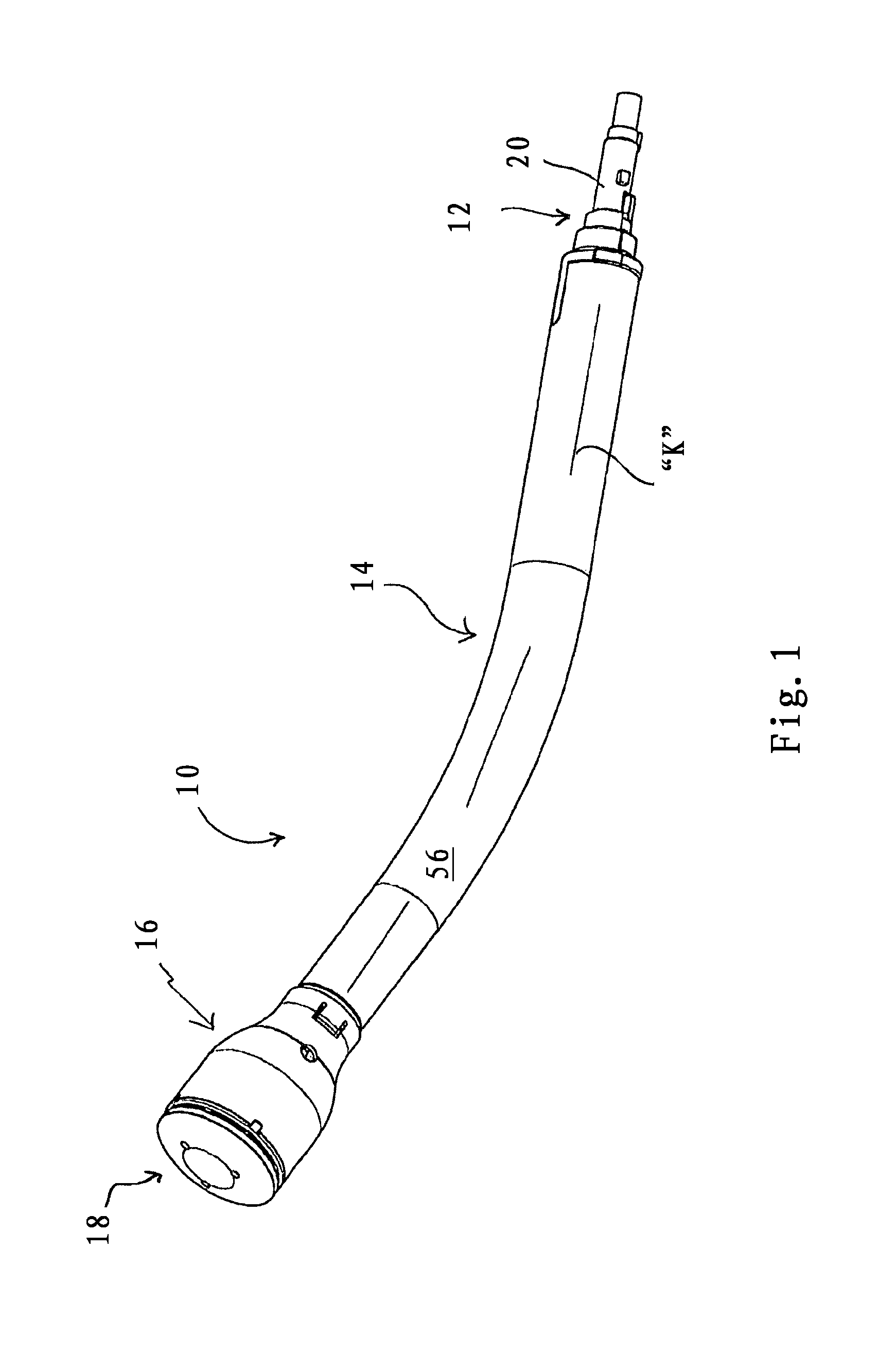
FIG. 1 is a perspective view of a surgical loading unit for performing a surgical stapling procedure in accordance with the principles of the present disclosure;
FIG. 2 is a side plan view of the surgical loading unit mounted to a surgical handle assembly;
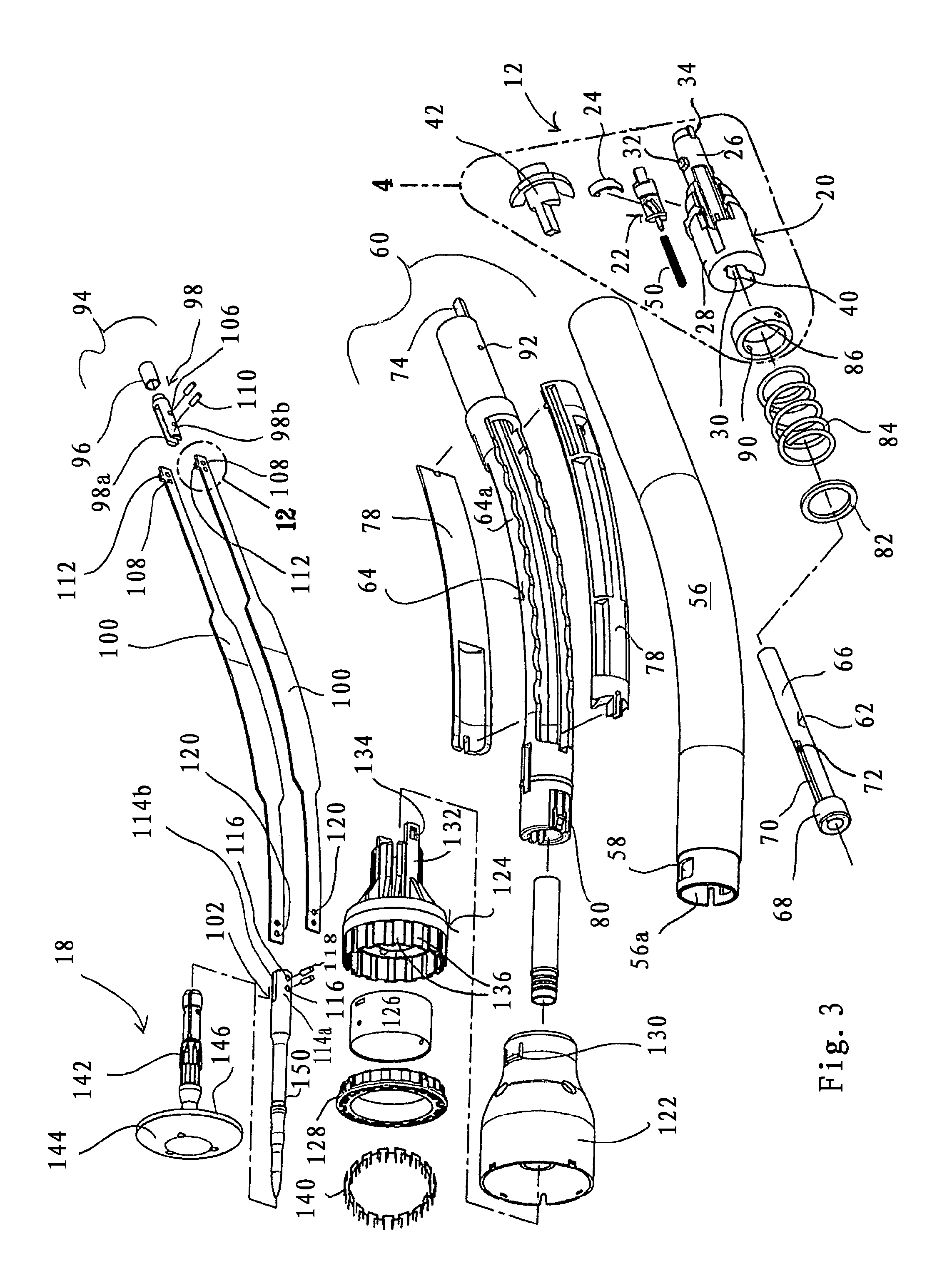
FIG. 3 is an exploded perspective view of the surgical loading unit;
FIG. 4 is an isolated view of the area of detail identified in FIG. 3 illustrating components of the handle mount of the surgical loading unit;
FIG. 5 is a perspective view of the lock member of the handle mount;
FIG. 6 is a perspective view with portions removed of the handle mount of the surgical loading unit illustrating the lock member in a lock position;
FIG. 7 is a perspective view of the handle mount illustrating the lock member in a release position;
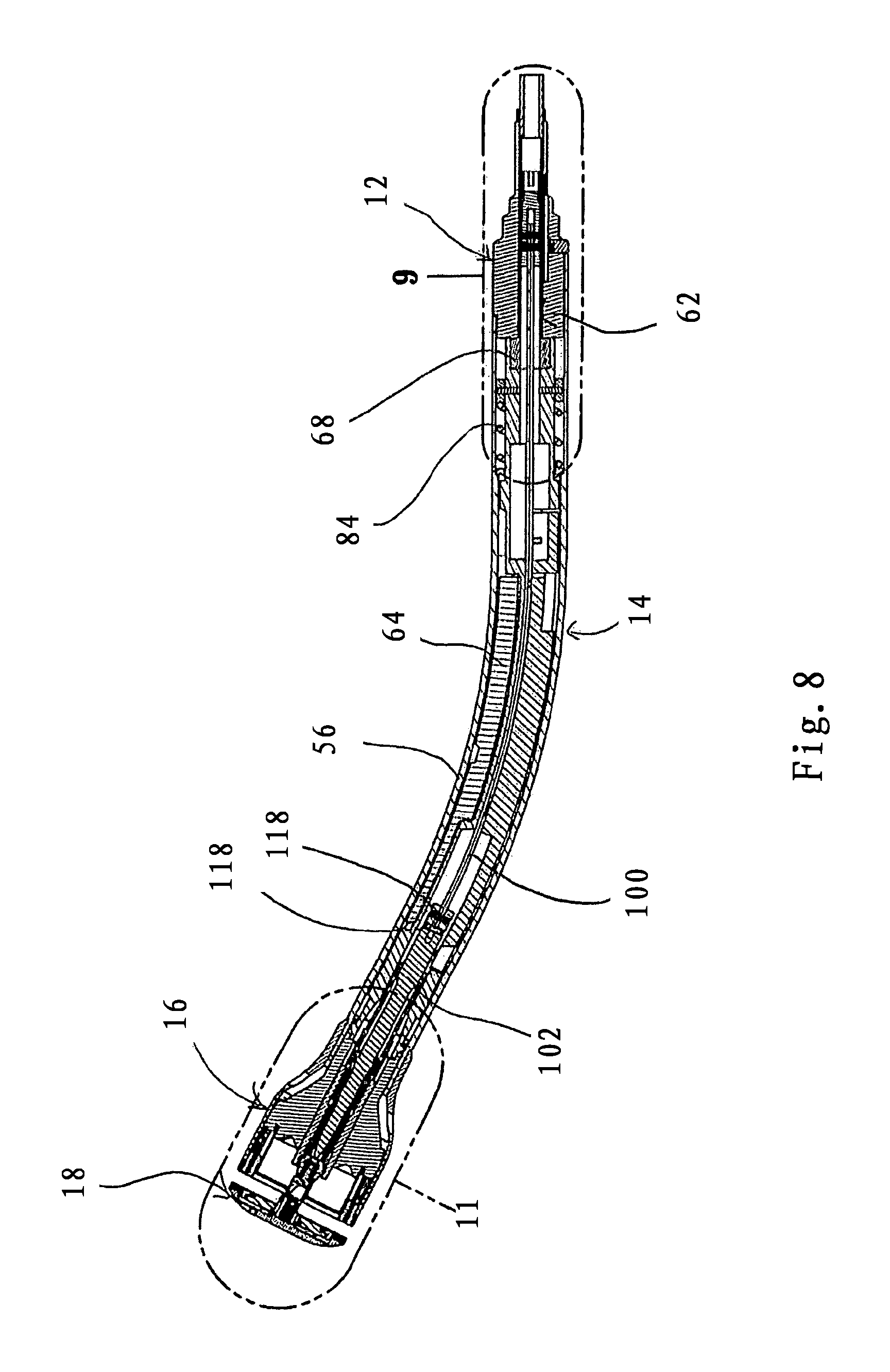
FIG. 8 is a side cross-sectional view of the surgical loading unit;
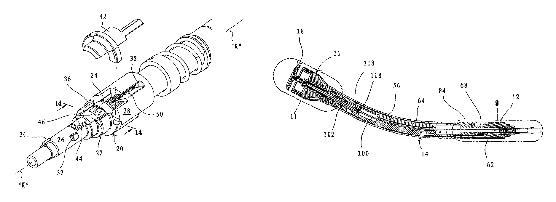
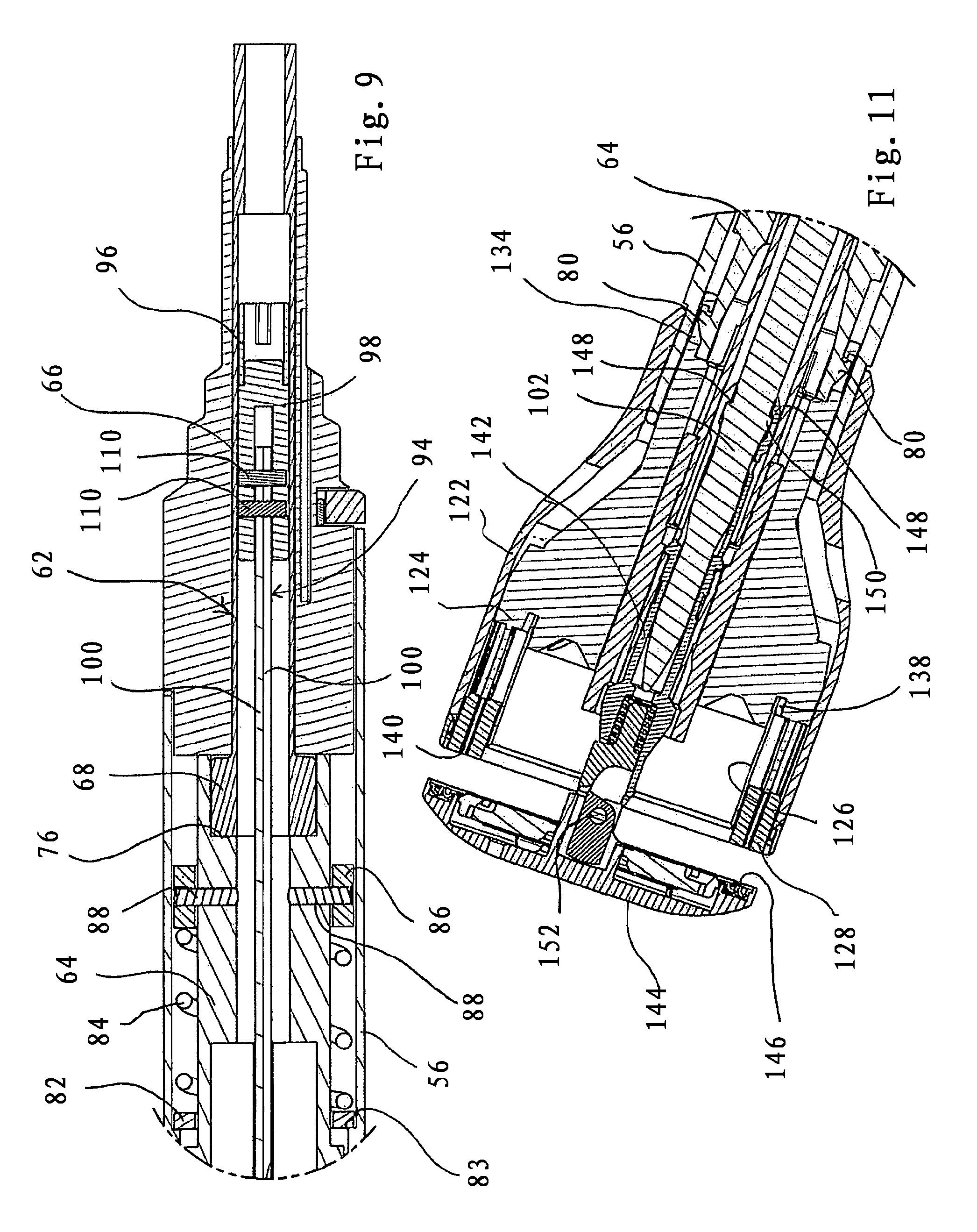
FIG. 9 is an isolated view of the area of detail identified in FIG. 8 illustrating a first side cross-sectional view of the handle mount with the lock member in the lock position;
FIG. 10 is a second side cross-sectional view of the handle mount with the lock member in the lock position;
FIG. 11 is an isolated view of the area of detail identified in FIG. 8;
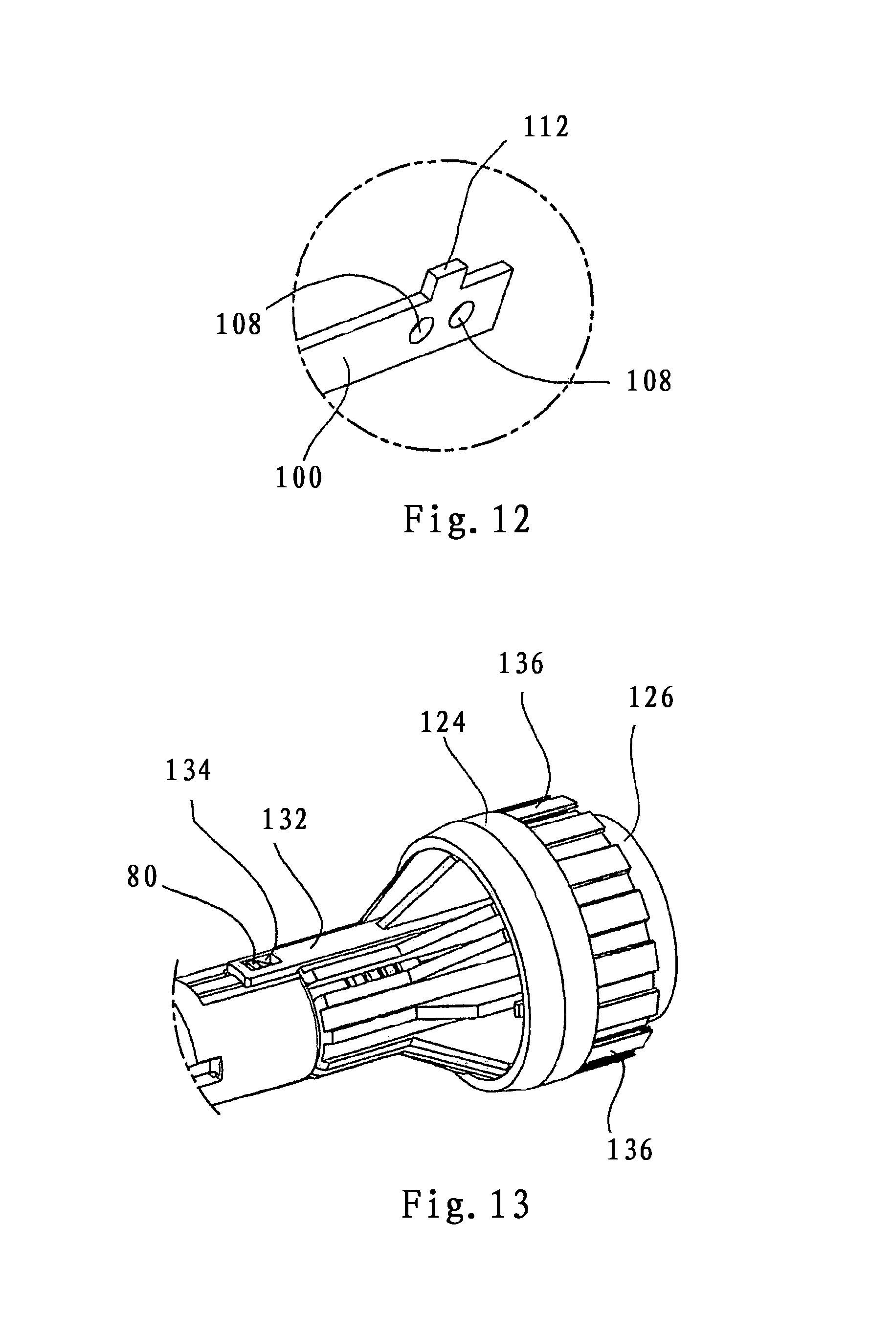
FIG. 12 is an isolated view of the area of detail identified in FIG. 3 illustrating the locking tabs of the anvil bands;
FIG. 13 is a perspective view of the staple cartridge assembly;
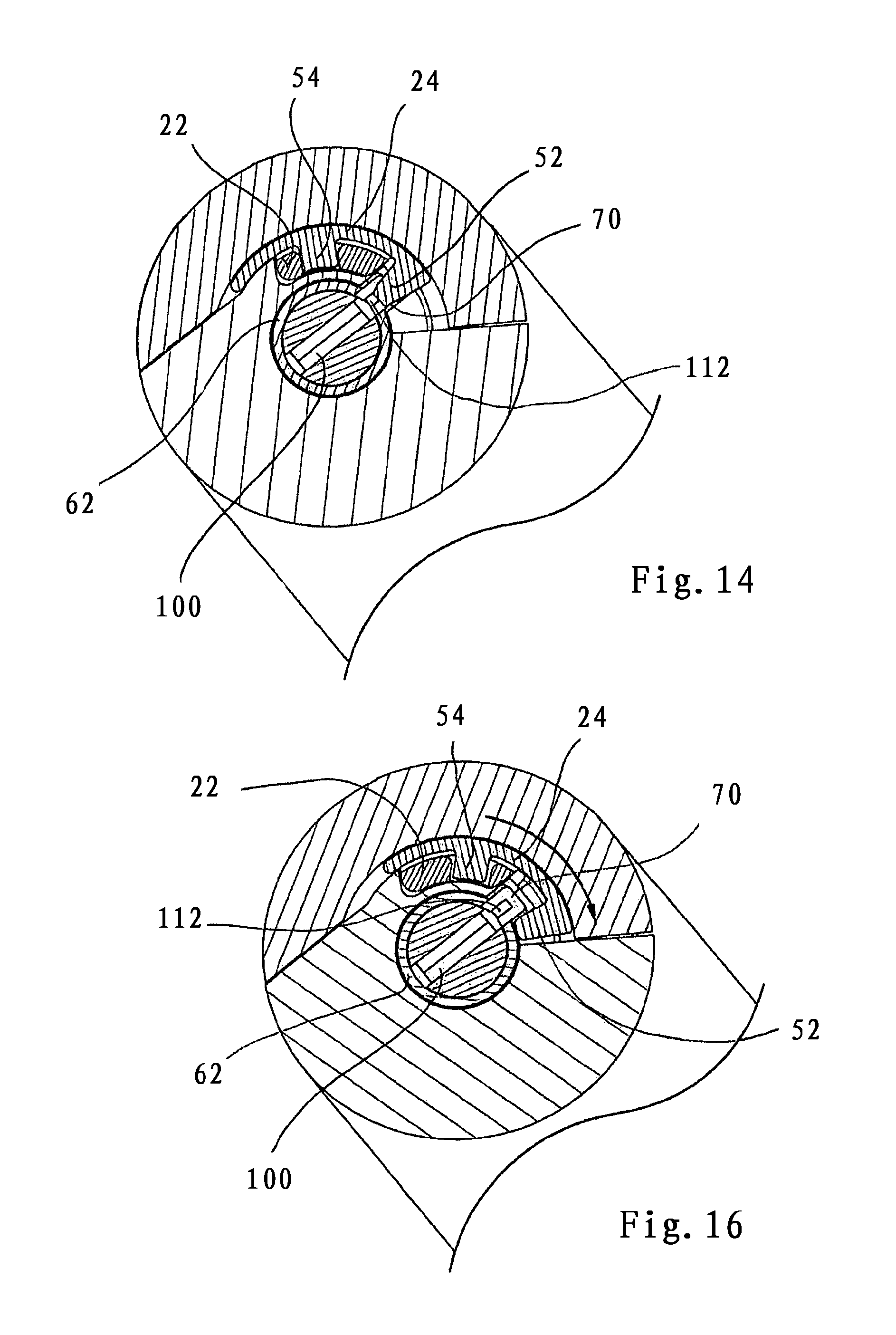
FIG. 14 is a cross-sectional view taken along the lines 14-14 of FIG. 6 illustrating the lock member in the lock position in secured engagement with the staple pusher and the anvil approximator;
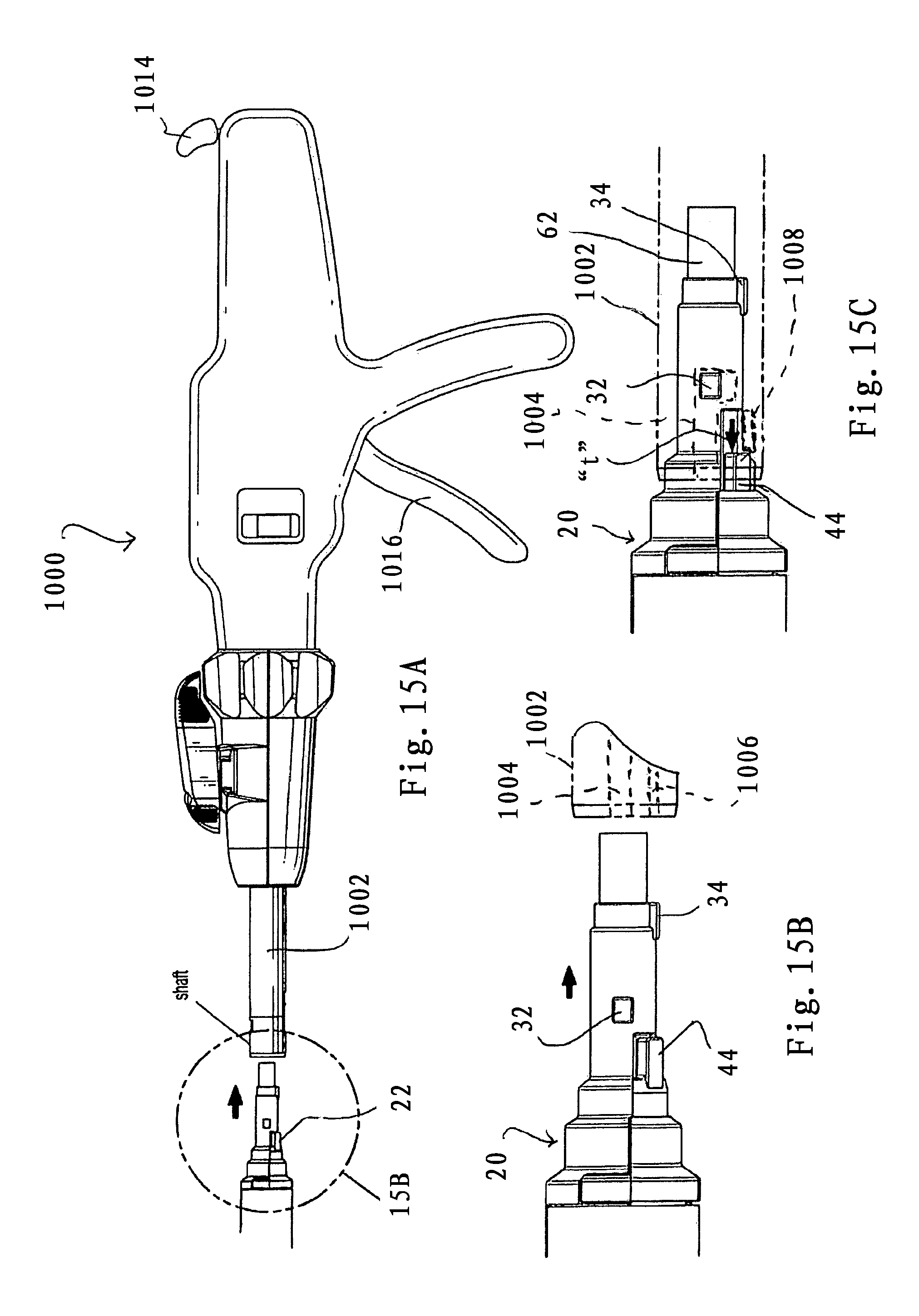
FIG. 15A is a side plan view illustrating mounting of the handle mount of the loading unit to the handle assembly;
FIG. 15B is an enlarged isolated view of the area of detail identified in FIG. 15A;
FIG. 15C is a view illustrating the handle mount mounted to the handle assembly and the guide member in the advanced position corresponding to the release position of the lock member;
FIG. 16 is a cross-sectional view taken along the lines 16-16 of FIG. 7 illustrating the lock member in the release position releasing the staple pusher and the anvil approximator;
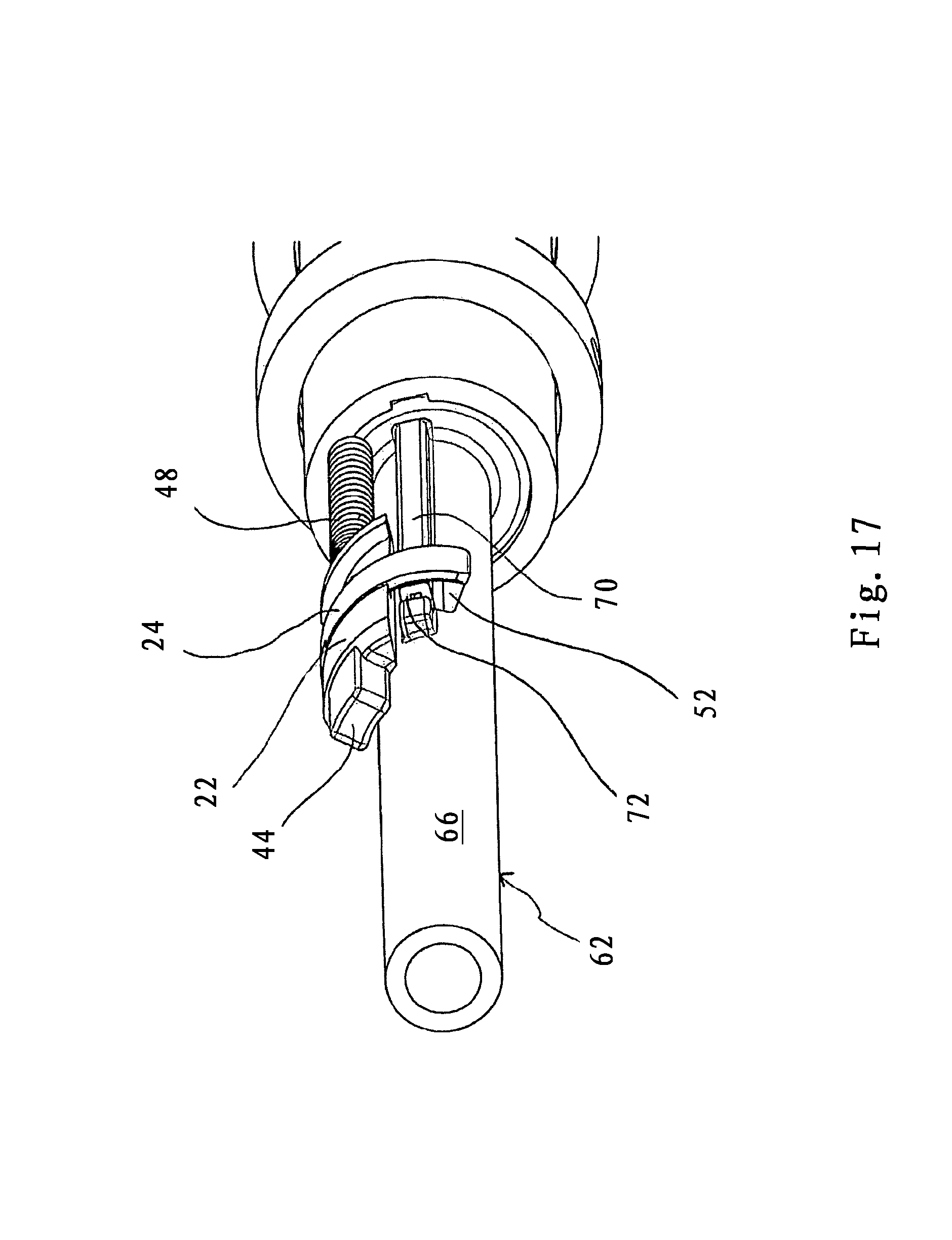
FIG. 17 is a perspective view of a portion of the handle mount illustrating the lock member in the release position;
FIG. 18 is a side cross-sectional view of the loading unit with a segment of the surgical handle assembly in phantom, illustrating the anvil assembly in an open condition upon advancement of the anvil approximator;
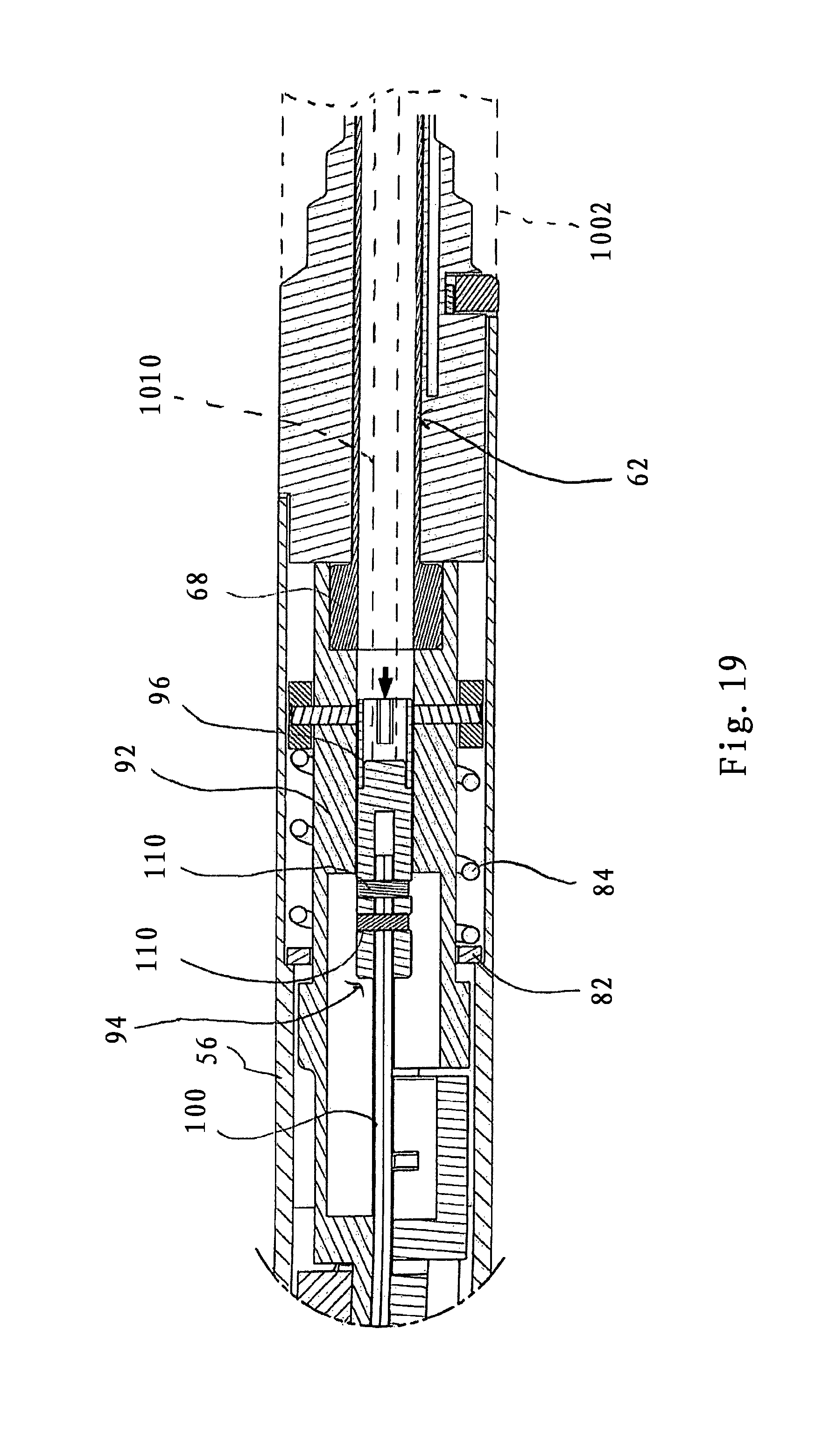
FIG. 19 is an isolated view of the area of detail of FIG. 18; and
FIG. 20 is a side cross-sectional view of the handle mount with a segment of the surgical handle assembly in phantom, illustrating the staple pusher advanced to fire the staples from the staple cartridge assembly.
DETAILED DESCRIPTION OF THE EMBODIMENT(S)
Particular embodiments of the present disclosure are described hereinbelow with reference to the accompanying drawings; however, it is to be understood that the disclosed embodiments are merely examples of the disclosure and may be embodied in various forms. Well-known functions or constructions are not described in detail to avoid obscuring the present disclosure in unnecessary detail. Therefore, specific structural and functional details disclosed herein are not to be interpreted as limiting, but merely as a basis for the claims and as a representative basis for teaching one skilled in the art to employ the present disclosure in virtually any appropriately detailed structure. Like reference numerals may refer to similar or identical elements throughout the description of the figures.
Referring now to the drawings where like reference numerals indicate similar components throughout the several views, FIGS. 1-2 illustrate the surgical loading unit in accordance with the principles of the present disclosure. In FIG. 1, the surgical loading unit 10 is depicted in isolation while in FIG. 2 the surgical loading unit 10 is depicted connected to a surgical handle assembly 1000. The surgical loading unit 10 and the surgical handle assembly 1000 form a surgical system adapted to perform a surgical procedure on tissue e.g., a circular or end-to-end anastomosis on tubular organs. The loading unit 10 may be a single use loading unit (SULU). It is also contemplated that the loading unit 10 may be a multi-use loading unit (MULU) adapted, e.g., for sequential firing of one or more staples.
The surgical handle assembly 1000 may be any handle assembly having at least one actuator, and in some embodiments, two actuators adapted to control operation of the loading unit 10. It is contemplated that the surgical handle assembly 1000 may be reusable, i.e., it can be reused with a plurality of loading units 10, and may be used with loading units having different stapling functions such as, e.g., linear stapling of tissue. Further details of the handle assembly 1000 and its interaction with the surgical loading unit 10 will be discussed in greater detail hereinbelow.
Referring now to FIGS. 3-6, in conjunction with FIG. 1, the surgical loading unit 10 will be discussed. The surgical loading unit 10 includes a handle mount 12 and an elongated segment 14 extending from the handle mount 12 and defining a longitudinal axis "k". A staple cartridge assembly 16 and an anvil assembly 18 are each mounted relative to the elongated segment 14. The handle mount 12 includes a mount frame 20, a release or guide member 22 mounted to the mount frame 20 and a lock member 24 mounted relative to the guide member 22. The mount frame 20 defines a proximal mounting segment 26 of generally cylindrical configuration and a distal segment 28 also of general cylindrical configuration and defining a larger diameter than the proximal mounting segment 26. The mount frame 20 defines a longitudinal passage 30 extending completely through the proximal mounting segment 26 and the distal segment 28. The proximal mounting segment 26 has diametrically opposed outer tabs 32 and an alignment tab 34 disposed at the proximal end of the mount frame 20. The opposed tabs 32 and the alignment tab 34 may cooperate with corresponding structure in the handle assembly 1000 to properly orient and secure the loading unit 10 relative to the handle assembly 1000, e.g., in a bayonet coupling relation. The mount frame 20 further includes a channeled groove 36 which receives the guide member 22. The channeled groove 36 terminates in a distal spring slot 38 defined within the distal segment 28 of the mount frame 20. The mount frame 20 also defines a keyed slot 40 extending through its distal face. A mount cover 42 is releasably couplable to the mount frame 20, and may be removed to permit assembly of the various components of the handle mount 12.
With reference to FIGS. 3-7, the guide member 22 is adapted for reciprocal longitudinal movement relative to the mount frame 20 and within the channeled groove 36 between a retracted position (FIG. 6) corresponding to a lock position of the lock member 24 and an advanced position (FIG. 7) corresponding to a release position of the lock member 24. The guide member 22 includes a proximal guide tab 44, a cam slot 46 obliquely arranged with respect to the longitudinal axis "k" of the elongated segment 14 (FIG. 1) and a spring pin 48 extending from the distal end of the guide member 22. The proximal guide tab 44 engages corresponding structure within the handle assembly 1000 to move the guide member 22 in the direction of directional arrow "t" (FIG. 7) from the retracted position to the advanced position during linear insertion of the handle mount 12 within the handle assembly 1000. A coil spring 50 is at least partially mounted about the spring pin 48 and is disposed within the distal spring slot 38 of the mount frame 20. The coil spring 50 biases the guide member 22 toward the retracted position depicted in FIG. 6 thereby maintaining the lock member 24 in the lock position.
The lock member 24 is adapted for rotational movement about the longitudinal axis from the lock position (FIG. 6) to the release position (FIG. 7) to releasably secure the operating components in the elongated segment 14, i.e., the staple pusher and the anvil approximator, which respectively controls operation of the staple cartridge assembly 16 and the anvil assembly 18. As best depicted in FIGS. 4 and 5, the lock member 24 includes a lock tab 52 and a channel boss 54. The lock tab 52 is operatively engagable with the operating components of the elongated segment 14 when the lock member 24 is in the lock position, e.g., prior to mounting the handle mount 12 to the handle assembly 1000, and releases the operating components when in the release position, e.g., when the handle mount 12 is mounted within the handle assembly 1000. The channel boss 54 is at least partially received within the cam slot 46 of the guide member 22. Upon movement of the guide member 22 from the retracted position (FIG. 6) to the advanced position (FIG. 7), the channel boss 54 traverses the cam slot 46 of the guide member 22, which causes the lock member 24 to rotate through a predetermined arc of rotation relative to the longitudinal axis "k" in the direction of directional arrow "b" (FIG. 7) from its lock position to its release position. Further details of the operation of the lock member 24 will be discussed in greater detail hereinbelow.
With reference to FIGS. 8-11, in conjunction with FIG. 3, the elongated segment 14 includes an outer member 56, which in one embodiment, is in the form of an outer tube defining a longitudinal opening 56a (FIG. 3), and is mounted to the handle mount 12 through conventional arrangements. For example, the proximal end of the outer member 56 may be mounted about the distal segment 28 of the handle mount 12 and secured via the use of adhesives, cements, fasteners, etc. The distal end of the outer member 56 may include a reduced diameter with opposed rectangular shaped windows 58 (FIG. 3) to assist in mounting the staple cartridge assembly 16 to the outer member 56.
Disposed within the outer member 56 is a staple pusher 60 including a staple connector 62 and a staple pusher tube 64 extending from the staple connector 62. The staple connector 62 is at least partially disposed within the longitudinal passage 30 of the handle mount 12 and incorporates a proximal cylindrical segment 66 and a distal collar segment 68. The proximal cylindrical segment 66 of the staple connector 62 includes a raised spline 70 (FIGS. 3 and 10) which defines a staple lock surface in the form of a lock slot 72 through which the lock tab 52 of the lock member 24 extends when in the lock position of the lock member 24. During movement of the lock member 24 to the release position, the lock tab 52 traverses the lock slot 72 to be released from the spline 70 and permit distal longitudinal movement of the staple connector 62 and the staple pusher tube 64.
As best depicted in FIGS. 9-10, the staple pusher tube 64 includes an alignment rod 74 which is received within the keyed slot 40 of the handle mount 12 to properly orient the staple pusher tube 64 relative to the handle mount 12. (see also FIG. 3) The proximal end of the staple pusher tube 64 defines a recess 76 which accommodates the distal collar segment 68 of the staple connector 62 to connect the two components. Adhesives and or cements may be used to securely fix the staple connector 62 and the staple pusher tube 64. The staple pusher tube 64 may include opposed wall segments or spacers 78 which couple to the main body 64a of the staple pusher tube 64 (FIG. 3). In the alternative, the main body 64a and the wall spacers 78 may be monolithically formed. The staple pusher tube 64 further defines diametrically opposed locking tabs 80 at its distal end which couple with the staple cartridge assembly 16 (see, e.g., FIGS. 3 and 11).
Referring to FIGS. 8-10, in conjunction with FIG. 3, the stapler pusher 60 is normally spring biased toward a proximal position. In one embodiment, the outer member 56 includes a washer 82 residing in an internal shelf 83 of the outer member 56 and a coil spring 84 which engages the washer 82 at the distal end of the coil spring 84. The staple pusher 60 includes a lock ring 86 which is secured to the proximal cylindrical segment 66 of the staple connector 62 (FIG. 3). The lock ring 86 includes lock pins 88 which extend through diametrically opposed openings 90 in the wall of the lock ring 86 and within aligned openings 92 in the wall of the staple connector 62 (FIG. 3). The lock pins 88 may be secured within the openings 90, 92 with the use of adhesives, cements or the like. The coil spring 84 engages the lock ring 86 to normally bias the lock ring 86 and the staple pusher 60 in a proximal direction.
Referring to FIGS. 8-11, an anvil approximator or drive 94 is at least partially disposed within the staple pusher 60 and the outer member 56. The anvil approximator 94 includes, from proximal to distal, an anvil sleeve 96, a connector 98 connected to the sleeve 96 and extending distally therefrom, a pair of elongate anvil bands 100 and an anvil retainer 102 coupled to the anvil bands 100. (see also FIG. 3) The anvil sleeve 96 includes structure which operatively engages at least one actuator within the handle assembly 1000. As depicted in FIG. 10, the structure may include a longitudinal opening 104 through which an anvil actuator of the handle assembly 1000 extends. The anvil sleeve 96 may define an internal shelf 105 or other coupling structure which engages with the anvil actuator of the handle assembly 1000. Other coupling mechanisms for coupling with the anvil actuator of the handle assembly 1000 are also envisioned.
The connector 98 defines first and second legs 98a, 98b with pairs of opposed openings 106 extending through the walls of the legs 98a, 98b. (FIG. 3) The proximal ends of the anvil bands 100 are received within the legs 98a, 98b of the connector 98 and also define pairs of openings 108 which are in general alignment with the openings 106 of the connector 98. (See FIGS. 3 and 12). A pair of pins 110 extends through the openings 106, 108 to couple the connector 98 with the anvil bands 100. At least one, e.g., both, of the anvil bands 100 include locking tabs 112 adjacent the proximal ends of the anvil bands 100. (FIG. 12) The locking tabs 112 define anvil lock surfaces which are engaged by the lock tab 52 of the lock member 24 within the handle mount 12 to releasably secure the anvil approximator 94 in a first position which corresponds to a closed condition of the anvil assembly 18 relative to the staple cartridge assembly 16 (FIG. 10). Upon movement of the lock member 24 to the release position, the lock tab 52 of the lock member 24 releases the locking tabs 112 of the anvil bands 100 to permit longitudinal movement of the anvil approximator 94 to a second position corresponding to an open condition of the anvil assembly 18.
With reference again to FIGS. 3 and 8, the anvil retainer 102 includes a pair of retainer legs 114a, 114b with pairs of openings 116 extending through the retainer legs 114a, 114b. The distal ends of the anvil bands 100 are received within the retainer legs 114a, 114b and secured to the anvil retainer 102 via pins 118 which extend through the openings 116 in the legs 114a, 114b and the corresponding openings 120 defined within the anvil bands 100.
With reference now to FIGS. 11 and 13, in conjunction with FIG. 3, the staple cartridge assembly 16 will be discussed. The staple cartridge assembly 16 includes an outer shell 122, an annular staple pusher ring 124, a cylindrical knife 126 and a staple guide 128. In FIG. 13, the outer shell 122 is removed for illustrative purposes. The outer shell 122 is mounted to the outer member 56 through cooperative engagement of shell locking detents 130 of the outer shell 122 with the rectangular shaped windows 58 of the outer member 56. (FIG. 3) The outer member 56 may define a reduced diameter which receives the shell 122 to maintain a substantial constant diameter through most of the length of the elongated segment 14. The pusher ring 124 includes a pair of locking legs 132 at its proximal end. The locking legs 132 include openings 134 which receive the locking tabs 80 of the staple pusher tube 64 to couple the staple pusher 60 with the staple pusher ring 124. Thus, movement of the staple pusher 60 causes corresponding movement of the staple pusher ring 124. The staple pusher ring 124 defines a plurality of pusher elements 136 arranged in a circular or annular array. The cylindrical knife 126 is at least partially received within an annular groove or channel 138 within the interior of the staple pusher ring 124, and may be secured within the pusher ring 124 via the use of adhesives or other means (FIG. 11). The staple guide 128 includes a plurality of staples 140 also arranged in an annular array. The staples 140 are ejected upon advancement of the staple pusher 60, the staple pusher ring 124 and the pusher elements 136.
The anvil assembly 18 includes an anvil shaft 142 and an anvil head 144 connected to the anvil shaft 142. (FIGS. 3 and 11) The anvil head 144 includes an annular anvil surface 146 which cooperates with the staples 140 to crimp the staples 140 during firing of the loading unit 10. The anvil shaft 142 is couplable to the anvil retainer 102. In one embodiment, the anvil shaft 142 includes one or more internal locking shelves 148 which cooperate with the outer locking ledge 150 on the anvil retainer 102 to releasably secure the anvil shaft 142 to the anvil retainer 102. The anvil shaft 142 may have sufficient resiliency or incorporate one or more deflectable components whereby the shaft 142 expands in diameter to receive the anvil retainer 102, and then returns towards its original diameter with the internal locking shelves 148 engaging the outer ledge 150 on the anvil retainer 102. Removal of the anvil assembly 18 relative to the anvil retainer 102 may be effected by pulling on either or both the anvil assembly 18 and the anvil retainer 102 to cause the anvil shaft 142 to expand in diameter such that the locking shelves 148 clear the outer locking ledge 150 of the anvil retainer 102. The anvil head 144 may articulate about pivot pin 152.
The use and operation of the surgical loading unit 10 and the handle assembly 1000 will now be discussed. As best depicted in FIG. 14, prior to mounting of the loading unit 10 to the handle assembly 1000, the lock member 24 is in the lock position in secured engagement with the staple pusher 60 and the anvil approximator 94. (see also FIG. 10) Specifically, the lock tab 52 of the lock member 24 is received within the lock slot 72 of the raised spline 70 of the staple connector 62, and also engages the locking tabs 112 of the anvil bands 100 of the anvil approximator 64. As discussed, the lock member 24 is normally biased to the lock position by the coil spring 50 which is engagement with the guide member 24 and normally biases the guide member 24 to its retracted position.
With reference now to FIGS. 15A-15C, the loading unit 10 is advanced toward the handle frame 1002 of the handle assembly 1000 with the outer tabs 32 and the alignment tab 34 of the loading unit 10 in general alignment with respective grooves 1004, 1006 (shown in phantom) of the handle frame 1002. The handle mount 12 is inserted within the handle frame 1002 of the handle assembly 1000. The loading unit 10 may be secured to the handle frame 1002 through rotation of the loading unit 10 to establish a bayonet coupling with the outer tabs 32 of the loading unit 10 and cooperating grooves 1004, 1006 of the handle assembly 1000. Other mechanisms for securing the loading unit 10 and the handle assembly 1000 are also envisioned including, e.g., a snap-lock relationship.
Upon mounting of the handle mount 12 within the surgical handle assembly 1000, the proximal guide tab 44 of the guide member 22 is engaged by corresponding structure within the handle assembly 1000 and is driven against the bias of the coil spring 50 in the direction of directional arrow "t" (FIGS. 7 and 15C). The corresponding structure may be an internal shelf, detent or similar structure identified schematically (in phantom) as reference numeral 1008, within the interior of the handle frame 1002. Movement of the guide member 22 causes the lock member 24 to rotate through a predetermined arc of rotation from the lock position of FIG. 14 to the released position of FIGS. 16 and 17 such that the lock tab 52 of the lock member 24 releases the lock slot 72 of the staple connector 62 and also releases the locking tabs 112 of the anvil bands 100 of the anvil approximator 94. In this position of the lock member 24, the staple pusher 60 and the anvil approximator 94 are free for longitudinal movement.
In addition, during mounting of the handle mount 12, at least one, e.g. first and second actuators, within the handle frame 1002 of the handle assembly 1000 couple with the anvil approximator 94 and the staple pusher 60. Any mechanisms for coupling the actuators of the handle assembly 1000 with the anvil approximator 94 and staple pusher 60 are envisioned, including, e.g., a bayonet coupling, interference fit or any other keyed or non-keyed coupling mechanisms. For example, with reference to FIGS. 18 and 19, the first or anvil actuator of the handle assembly 1000, identified schematically (in phantom) as reference numeral 1010, may be coupled to the anvil sleeve 96 through insertion of the distal end of the first actuator 1010 through the longitudinal opening 104 of the anvil sleeve 96. (FIG. 10). The first actuator 1010 may have a spring-biased detent which flexes inwardly to be passed through the longitudinal opening 104, and then returns under the influence of its normal spring bias to engage the internal shelf 105 of the anvil sleeve 96 to couple the components. The second or staple actuator of the handle assembly 1000, identified schematically (in phantom) as reference numeral 1012 in FIG. 20, may abut or engage the proximal end of the staple connector 62. Other arrangements are also envisioned.
The procedure may be continued by advancing the anvil actuator 1010 of the handle assembly 1000 via manual member 1014 (FIG. 2) connected to the anvil actuator 1010 (by conventional means) to move the anvil approximator 94 (including the anvil sleeve 96 and the anvil bands 100) in the distal direction from its first position to its second position to cause distal displacement of the anvil assembly 18 to its open condition relative to the staple cartridge assembly 16 (FIGS. 18 and 19). Prior or subsequent to advancement of the anvil approximator 94, the anvil retainer 102 may be mounted to the anvil shaft 142 of the anvil assembly 18 in the manner discussed hereinabove. The anvil assembly 18 may be positioned relative to a tubular organ or tissue and the anvil approximator 94 may be returned to its first position, as depicted in FIG. 20, by movement of the anvil actuator 1010 via manual member 1014 of the handle assembly 1000 in, e.g., a proximal direction, to position the anvil assembly 18 in its closed condition (FIG. 2) relative to the staple cartridge assembly 16. The staple cartridge assembly 16 is positioned relative to the tissue. Thereafter, the staple actuator 1012 of the handle assembly 1000 is actuated via manual member 1016 of the handle assembly 1000 (FIG. 2), which is connected to the staple actuator 1012 by conventional means, to advance the staple actuator 1012 and the staple connector 62 (and the staple pusher 60) as depicted in FIG. 20. Advancement of the staple connector 62 causes corresponding advancement of the staple pusher ring 124 and the cylindrical knife 126 of the staple cartridge assembly 16 to expel the staples 140 which are crimped by the anvil surface 146 of the anvil head 144 thereby joining the tissue or tubular organs and creating an opening therebetween with the cylindrical knife 146.
Subsequent to use of the loading unit 10, the loading unit 10 may be released from the handle assembly 1000 and disposed, or reloaded and sterilized for subsequent use. Alternatively, a second loading unit 10 can be mounted to the handle assembly 1000 to perform additional stapling or fastening functions and/or other procedures.
It will be understood that various modifications may be made to the embodiments disclosed herein. For example, the above described lockout mechanism may be incorporated into a variety of surgical instruments which include loading units and is not solely limited to use on staplers systems adapted to perform an end-to-end or circular anastomosis of tissue. For example, the loading unit may be adapted to fire clips or any other fastener dimensioned to attach tissue, including linear attachment of tissue. Therefore, the above description should not be construed as limiting, but merely as exemplifications of various embodiments. Those skilled in the art will envision other modifications within the scope and spirit of the claims appended hereto.
* * * * *
D00000
D00001
D00002
D00003
D00004
D00005
D00006
D00007
D00008
D00009
D00010
D00011
D00012
D00013

D00014
D00015

XML
uspto.report is an independent third-party trademark research tool that is not affiliated, endorsed, or sponsored by the United States Patent and Trademark Office (USPTO) or any other governmental organization. The information provided by uspto.report is based on publicly available data at the time of writing and is intended for informational purposes only.
While we strive to provide accurate and up-to-date information, we do not guarantee the accuracy, completeness, reliability, or suitability of the information displayed on this site. The use of this site is at your own risk. Any reliance you place on such information is therefore strictly at your own risk.
All official trademark data, including owner information, should be verified by visiting the official USPTO website at www.uspto.gov. This site is not intended to replace professional legal advice and should not be used as a substitute for consulting with a legal professional who is knowledgeable about trademark law.