Replacement heart valve
Quadri , et al. Nov
U.S. patent number 10,485,660 [Application Number 15/422,397] was granted by the patent office on 2019-11-26 for replacement heart valve. This patent grant is currently assigned to Edwards Lifesciences CardiAQ LLC. The grantee listed for this patent is Edwards Lifesciences CardiAQ LLC. Invention is credited to Arshad Quadri, J. Brent Ratz.


View All Diagrams
| United States Patent | 10,485,660 |
| Quadri , et al. | November 26, 2019 |
Replacement heart valve
Abstract
A replacement heart valve can have an expandable frame configured to engage a native valve annulus. A valve body can be mounted onto the expandable frame to provide functionality similar to a natural valve. The valve body has an upstream end and a downstream end, and a diameter at the downstream end is greater than a diameter at the upstream end.
| Inventors: | Quadri; Arshad (West Hartford, CT), Ratz; J. Brent (Winchester, MA) | ||||||||||
|---|---|---|---|---|---|---|---|---|---|---|---|
| Applicant: |
|
||||||||||
| Assignee: | Edwards Lifesciences CardiAQ
LLC (Irvine, CA) |
||||||||||
| Family ID: | 45329341 | ||||||||||
| Appl. No.: | 15/422,397 | ||||||||||
| Filed: | February 1, 2017 |
Prior Publication Data
| Document Identifier | Publication Date | |
|---|---|---|
| US 20170354497 A1 | Dec 14, 2017 | |
Related U.S. Patent Documents
| Application Number | Filing Date | Patent Number | Issue Date | ||
|---|---|---|---|---|---|
| 13165721 | Jun 21, 2011 | ||||
| 61357048 | Jun 21, 2010 | ||||
| Current U.S. Class: | 1/1 |
| Current CPC Class: | A61F 2/2415 (20130101); A61F 2/2418 (20130101); A61F 2250/0029 (20130101); A61F 2230/008 (20130101); A61F 2230/0067 (20130101); A61F 2220/0008 (20130101); A61F 2230/0054 (20130101); A61F 2250/0039 (20130101) |
| Current International Class: | A61F 2/24 (20060101) |
References Cited [Referenced By]
U.S. Patent Documents
| 3657744 | April 1972 | Ersek |
| 3671979 | June 1972 | Moulopoulos |
| 3739402 | June 1973 | Cooley et al. |
| 4056854 | November 1977 | Boretos et al. |
| 4079468 | March 1978 | Liotta et al. |
| 4204283 | May 1980 | Bellhouse et al. |
| 4222126 | September 1980 | Boretos et al. |
| 4265694 | May 1981 | Boretos et al. |
| 4339831 | July 1982 | Johnson |
| 4340977 | July 1982 | Brownlee et al. |
| 4470157 | September 1984 | Love |
| 4477930 | October 1984 | Totten et al. |
| 4490859 | January 1985 | Black et al. |
| 4553545 | November 1985 | Maass et al. |
| 4777951 | October 1988 | Cribier et al. |
| 4865600 | September 1989 | Carpentier et al. |
| 4994077 | February 1991 | Dobben |
| 5326371 | July 1994 | Love et al. |
| 5332402 | July 1994 | Teitelbaum |
| 5370685 | December 1994 | Stevens |
| 5411552 | May 1995 | Andersen et al. |
| 5415667 | May 1995 | Frater |
| 5545214 | August 1996 | Stevens |
| 5554185 | September 1996 | Block et al. |
| 5697382 | December 1997 | Love et al. |
| 5840081 | November 1998 | Andersen et al. |
| 5855601 | January 1999 | Bessler et al. |
| 5957949 | September 1999 | Leonhardt et al. |
| 6086612 | July 2000 | Jansen |
| 6113631 | September 2000 | Jansen |
| 6168614 | January 2001 | Andersen et al. |
| 6251093 | June 2001 | Valley et al. |
| 6312465 | November 2001 | Griffin et al. |
| 6358277 | March 2002 | Duran |
| 6440164 | August 2002 | DiMatteo et al. |
| 6458153 | October 2002 | Bailey et al. |
| 6482228 | November 2002 | Norred |
| 6511491 | January 2003 | Grudem et al. |
| 6527800 | March 2003 | McGuckin, Jr. et al. |
| 6582462 | June 2003 | Andersen et al. |
| 6610088 | August 2003 | Gabbay |
| 6629534 | October 2003 | St. Goar et al. |
| 6652578 | November 2003 | Bailey et al. |
| 6676698 | January 2004 | McGuckin, Jr. et al. |
| 6695878 | February 2004 | McGuckin, Jr. et al. |
| 6712836 | March 2004 | Berg et al. |
| 6716207 | April 2004 | Farnholtz |
| 6729356 | May 2004 | Baker et al. |
| 6730118 | May 2004 | Spenser et al. |
| 6746422 | June 2004 | Noriega et al. |
| 6749560 | June 2004 | Konstorum et al. |
| 6767362 | July 2004 | Schreck |
| 6780200 | August 2004 | Jansen |
| 6790229 | September 2004 | Berreklouw |
| 6790230 | September 2004 | Beyersdorf et al. |
| 6875231 | April 2005 | Anduiza et al. |
| 6893460 | May 2005 | Spenser et al. |
| 6908481 | June 2005 | Cribier |
| 7018406 | March 2006 | Seguin et al. |
| 7186265 | March 2007 | Sharkawy et al. |
| 7192440 | March 2007 | Andreas et al. |
| 7198646 | April 2007 | Figulla et al. |
| 7201772 | April 2007 | Schwammenthal et al. |
| 7252682 | August 2007 | Seguin |
| 7276078 | October 2007 | Spenser et al. |
| 7329278 | February 2008 | Seguin et al. |
| 7381219 | June 2008 | Salahieh et al. |
| 7393360 | July 2008 | Spenser et al. |
| 7429269 | September 2008 | Schwammenthal et al. |
| 7442204 | October 2008 | Schwammenthal et al. |
| 7445631 | November 2008 | Salahieh et al. |
| 7462191 | December 2008 | Spenser et al. |
| 7510575 | March 2009 | Spenser et al. |
| 7524330 | April 2009 | Berreklouw |
| 7553324 | June 2009 | Andreas et al. |
| 7585321 | September 2009 | Cribier |
| 7618446 | November 2009 | Andersen et al. |
| 7621948 | November 2009 | Herrmann et al. |
| 7628805 | December 2009 | Spenser et al. |
| 7748389 | July 2010 | Salahieh et al. |
| 7753949 | July 2010 | Lamphere et al. |
| 7803185 | September 2010 | Gabbay |
| 7806919 | October 2010 | Bloom et al. |
| 7815673 | October 2010 | Bloom et al. |
| 7824443 | November 2010 | Salahieh et al. |
| 7892281 | February 2011 | Seguin et al. |
| 7914569 | March 2011 | Nguyen et al. |
| 7947075 | May 2011 | Goetz et al. |
| 7959672 | June 2011 | Salahieh et al. |
| 7972378 | July 2011 | Tabor et al. |
| 7981151 | July 2011 | Rowe |
| 7993392 | August 2011 | Righini et al. |
| 8016877 | September 2011 | Seguin et al. |
| 8048153 | November 2011 | Salahieh et al. |
| 8052750 | November 2011 | Tuval et al. |
| 8070800 | December 2011 | Lock et al. |
| 8070802 | December 2011 | Lamphere et al. |
| 8075615 | December 2011 | Eberhardt et al. |
| 8080054 | December 2011 | Rowe |
| 8092520 | January 2012 | Quadri |
| 8109996 | February 2012 | Stacchino et al. |
| 8118866 | February 2012 | Herrmann et al. |
| 8136218 | March 2012 | Millwee et al. |
| 8137398 | March 2012 | Tuval et al. |
| 8157852 | April 2012 | Bloom et al. |
| 8167934 | May 2012 | Styrc et al. |
| 8182528 | May 2012 | Salahieh et al. |
| 8182530 | May 2012 | Huber |
| 8216301 | July 2012 | Bonhoeffer et al. |
| 8219229 | July 2012 | Cao et al. |
| 8220121 | July 2012 | Hendriksen et al. |
| 8221493 | July 2012 | Boyle et al. |
| 8226710 | July 2012 | Nguyen et al. |
| 8236045 | August 2012 | Benichou et al. |
| 8246675 | August 2012 | Zegdi |
| 8246678 | August 2012 | Salahieh et al. |
| 8252051 | August 2012 | Chau et al. |
| 8252052 | August 2012 | Salahieh et al. |
| 8287584 | October 2012 | Salahieh et al. |
| 8303653 | November 2012 | Bonhoeffer et al. |
| 8313525 | November 2012 | Tuval et al. |
| 8323335 | December 2012 | Rowe et al. |
| 8353953 | January 2013 | Giannetti et al. |
| 8403983 | March 2013 | Quadri et al. |
| 8414644 | April 2013 | Quadri et al. |
| 8414645 | April 2013 | Dwork et al. |
| 8444689 | May 2013 | Zhang |
| 8449599 | May 2013 | Chau et al. |
| 8454685 | June 2013 | Hariton et al. |
| 8460368 | June 2013 | Taylor et al. |
| 8470023 | June 2013 | Eidenschink et al. |
| 8475521 | July 2013 | Suri et al. |
| 8475523 | July 2013 | Duffy |
| 8479380 | July 2013 | Malewicz et al. |
| 8486137 | July 2013 | Suri et al. |
| 8491650 | July 2013 | Wiemeyer et al. |
| 8500733 | August 2013 | Watson |
| 8500798 | August 2013 | Rowe et al. |
| 8511244 | August 2013 | Holecek et al. |
| 8512401 | August 2013 | Murray, III et al. |
| 8518096 | August 2013 | Nelson |
| 8518106 | August 2013 | Duffy et al. |
| 8562663 | October 2013 | Mearns et al. |
| 8579963 | November 2013 | Tabor |
| 8579964 | November 2013 | Lane et al. |
| 8579965 | November 2013 | Bonhoeffer et al. |
| 8585755 | November 2013 | Chau et al. |
| 8585756 | November 2013 | Bonhoeffer et al. |
| 8591570 | November 2013 | Revuelta et al. |
| 8597348 | December 2013 | Rowe et al. |
| 8617236 | December 2013 | Paul et al. |
| 8640521 | February 2014 | Righini et al. |
| 8647381 | February 2014 | Essinger et al. |
| 8652145 | February 2014 | Maimon et al. |
| 8652201 | February 2014 | Oberti et al. |
| 8652202 | February 2014 | Alon et al. |
| 8652203 | February 2014 | Quadri et al. |
| 8668733 | March 2014 | Haug et al. |
| 8673000 | March 2014 | Tabor et al. |
| 8679174 | March 2014 | Ottma et al. |
| 8679404 | March 2014 | Liburd et al. |
| 8685086 | April 2014 | Navia et al. |
| 8721708 | May 2014 | Seguin et al. |
| 8721714 | May 2014 | Kelley |
| 8728154 | May 2014 | Alkhatib |
| 8728155 | May 2014 | Montorfano et al. |
| 8740974 | June 2014 | Lambrecht et al. |
| 8740976 | June 2014 | Tran et al. |
| 8747458 | June 2014 | Tuval et al. |
| 8747459 | June 2014 | Nguyen et al. |
| 8747460 | June 2014 | Tuval et al. |
| 8758432 | June 2014 | Solem |
| 8764818 | July 2014 | Gregg |
| 8771344 | July 2014 | Tran et al. |
| 8771345 | July 2014 | Tuval et al. |
| 8771346 | July 2014 | Tuval et al. |
| 8778020 | July 2014 | Gregg et al. |
| 8784337 | July 2014 | Voeller et al. |
| 8784478 | July 2014 | Tuval et al. |
| 8784481 | July 2014 | Alkhatib et al. |
| 8790387 | July 2014 | Nguyen et al. |
| 8795356 | August 2014 | Quadri et al. |
| 8795357 | August 2014 | Yohanan et al. |
| 8808356 | August 2014 | Braido et al. |
| 8828078 | September 2014 | Salahieh et al. |
| 8828079 | September 2014 | Thielen et al. |
| 8834564 | September 2014 | Tuval et al. |
| 8845718 | September 2014 | Tuval et al. |
| 8858620 | October 2014 | Salahieh et al. |
| 8870948 | October 2014 | Erzberger et al. |
| 8870950 | October 2014 | Hacohen |
| 8876893 | November 2014 | Dwork et al. |
| 8876894 | November 2014 | Tuval et al. |
| 8876895 | November 2014 | Tuval et al. |
| 8911455 | December 2014 | Quadri et al. |
| 8926693 | January 2015 | Duffy et al. |
| 8926694 | January 2015 | Costello |
| 8939960 | January 2015 | Rosenman et al. |
| 8945209 | February 2015 | Bonyuet et al. |
| 8951299 | February 2015 | Paul et al. |
| 8961593 | February 2015 | Bonhoeffer et al. |
| 8961595 | February 2015 | Alkhatib |
| 8974524 | March 2015 | Yeung et al. |
| 8979922 | March 2015 | Jayasinghe et al. |
| 8986372 | March 2015 | Murry, III et al. |
| 8986375 | March 2015 | Garde et al. |
| 8992608 | March 2015 | Haug et al. |
| 8998979 | April 2015 | Seguin et al. |
| 8998980 | April 2015 | Shipley et al. |
| 9005273 | April 2015 | Salahieh et al. |
| 9011521 | April 2015 | Haug et al. |
| 9011523 | April 2015 | Seguin |
| 9011524 | April 2015 | Eberhardt |
| 9028545 | May 2015 | Taylor |
| 9034032 | May 2015 | McLean et al. |
| 9034033 | May 2015 | McLean et al. |
| 9039757 | May 2015 | McLean et al. |
| 9055937 | June 2015 | Rowe et al. |
| 9066801 | June 2015 | Kovalsky et al. |
| 9078749 | July 2015 | Lutter et al. |
| 9078751 | July 2015 | Naor |
| 9084676 | July 2015 | Chau et al. |
| 9125738 | September 2015 | Figulla et al. |
| 9138312 | September 2015 | Tuval et al. |
| 9161834 | October 2015 | Taylor et al. |
| 9173737 | November 2015 | Hill et al. |
| 9180004 | November 2015 | Alkhatib |
| 9186249 | November 2015 | Rolando et al. |
| 9220594 | December 2015 | Braido et al. |
| 9241790 | January 2016 | Lane et al. |
| 9248014 | February 2016 | Lane et al. |
| 9277990 | March 2016 | Klima et al. |
| 9277993 | March 2016 | Gamarra et al. |
| 9289291 | March 2016 | Gorman, III et al. |
| 9289296 | March 2016 | Braido et al. |
| 9295551 | March 2016 | Straubinger et al. |
| 9326815 | May 2016 | Watson |
| 9331328 | May 2016 | Eberhardt et al. |
| 9339382 | May 2016 | Tabor et al. |
| 9351831 | May 2016 | Braido et al. |
| 9351832 | May 2016 | Braido et al. |
| 9364321 | June 2016 | Alkhatib et al. |
| 9445897 | September 2016 | Bishop et al. |
| 9456877 | October 2016 | Weitzner et al. |
| 9681968 | June 2017 | Goetz et al. |
| 9700329 | July 2017 | Metzger et al. |
| 9700411 | July 2017 | Klima et al. |
| 9795479 | October 2017 | Lim et al. |
| 9833313 | December 2017 | Board et al. |
| 9861473 | January 2018 | Lafontaine |
| 9861476 | January 2018 | Salahieh et al. |
| 9861477 | January 2018 | Backus et al. |
| 9867698 | January 2018 | Kovalsky et al. |
| 9877830 | January 2018 | Lim et al. |
| 9889029 | February 2018 | Li et al. |
| 9895225 | February 2018 | Rolando et al. |
| 9925045 | March 2018 | Creaven et al. |
| 2001/0007956 | July 2001 | Letac et al. |
| 2002/0016623 | February 2002 | Kula et al. |
| 2002/0032481 | March 2002 | Gabbay |
| 2002/0045929 | April 2002 | Diaz |
| 2002/0052644 | May 2002 | Shaolian et al. |
| 2003/0105517 | June 2003 | White et al. |
| 2003/0120333 | June 2003 | Ouriel et al. |
| 2003/0130729 | July 2003 | Paniagua et al. |
| 2003/0176914 | September 2003 | Rabkin et al. |
| 2003/0199971 | October 2003 | Tower et al. |
| 2003/0220683 | November 2003 | Minasian et al. |
| 2004/0117009 | June 2004 | Cali et al. |
| 2004/0133273 | July 2004 | Cox |
| 2004/0186561 | September 2004 | McGuckin et al. |
| 2004/0210304 | October 2004 | Seguin et al. |
| 2004/0210307 | October 2004 | Khairkhahan |
| 2004/0215325 | October 2004 | Penn et al. |
| 2004/0225353 | November 2004 | McGuckin et al. |
| 2004/0236411 | November 2004 | Sarac et al. |
| 2005/0033398 | February 2005 | Seguin |
| 2005/0075727 | April 2005 | Wheatley |
| 2005/0090887 | April 2005 | Pryor |
| 2005/0096738 | May 2005 | Cali et al. |
| 2005/0107872 | May 2005 | Mensah et al. |
| 2005/0137682 | June 2005 | Justino |
| 2005/0137686 | June 2005 | Salahieh et al. |
| 2005/0137687 | June 2005 | Salahieh et al. |
| 2005/0137691 | June 2005 | Salahieh et al. |
| 2005/0137693 | June 2005 | Haug et al. |
| 2005/0159811 | July 2005 | Lane |
| 2005/0182486 | August 2005 | Gabbay |
| 2005/0216079 | September 2005 | MaCoviak |
| 2005/0234546 | October 2005 | Nugent et al. |
| 2005/0283231 | December 2005 | Haug et al. |
| 2006/0020327 | January 2006 | Lashinski et al. |
| 2006/0052867 | March 2006 | Revuelta et al. |
| 2006/0058872 | March 2006 | Salahieh et al. |
| 2006/0095115 | May 2006 | Bladillah et al. |
| 2006/0173537 | August 2006 | Yang et al. |
| 2006/0195183 | August 2006 | Navia et al. |
| 2006/0212110 | September 2006 | Osborne et al. |
| 2006/0241745 | October 2006 | Solem |
| 2006/0259135 | November 2006 | Navia et al. |
| 2006/0265056 | November 2006 | Nguyen et al. |
| 2006/0287717 | December 2006 | Rowe et al. |
| 2006/0293745 | December 2006 | Carpentier et al. |
| 2007/0010876 | January 2007 | Salahieh et al. |
| 2007/0043435 | February 2007 | Seguin et al. |
| 2007/0050021 | March 2007 | Johnson |
| 2007/0100432 | May 2007 | Case et al. |
| 2007/0129794 | June 2007 | Realyvasquez |
| 2007/0142906 | June 2007 | Figulla et al. |
| 2007/0213813 | September 2007 | Von Segesser et al. |
| 2007/0255394 | November 2007 | Ryan |
| 2008/0021546 | January 2008 | Patz et al. |
| 2008/0071361 | March 2008 | Tuval |
| 2008/0071366 | March 2008 | Tuval et al. |
| 2008/0082164 | April 2008 | Friedman |
| 2008/0082165 | April 2008 | Wilson et al. |
| 2008/0097581 | April 2008 | Shanley |
| 2008/0147179 | June 2008 | Cai et al. |
| 2008/0147183 | June 2008 | Styrc |
| 2008/0161911 | July 2008 | Revuelta et al. |
| 2008/0177381 | July 2008 | Navia et al. |
| 2008/0183273 | July 2008 | Mesana et al. |
| 2008/0208328 | August 2008 | Antocci et al. |
| 2008/0228254 | September 2008 | Ryan |
| 2009/0005863 | January 2009 | Goetz et al. |
| 2009/0138079 | May 2009 | Tuval et al. |
| 2009/0171456 | July 2009 | Kveen et al. |
| 2009/0182413 | July 2009 | Burkart et al. |
| 2009/0188964 | July 2009 | Orlov |
| 2009/0270972 | October 2009 | Lane |
| 2009/0276027 | November 2009 | Glynn |
| 2009/0276040 | November 2009 | Rowe et al. |
| 2009/0281618 | November 2009 | Hill et al. |
| 2009/0287296 | November 2009 | Manasse |
| 2009/0292350 | November 2009 | Eberhardt et al. |
| 2009/0306768 | December 2009 | Quadri |
| 2010/0082094 | April 2010 | Quadri et al. |
| 2010/0114305 | May 2010 | Kang et al. |
| 2010/0191326 | July 2010 | Alkhatib |
| 2010/0217382 | August 2010 | Chau et al. |
| 2010/0249894 | September 2010 | Oba et al. |
| 2010/0249911 | September 2010 | Alkhatib |
| 2010/0256723 | October 2010 | Murray |
| 2010/0305685 | December 2010 | Millwee et al. |
| 2011/0004296 | January 2011 | Lutter et al. |
| 2011/0029067 | February 2011 | McGuckin, Jr. et al. |
| 2011/0208297 | August 2011 | Tuval et al. |
| 2011/0208298 | August 2011 | Tuval et al. |
| 2011/0224785 | September 2011 | Hacohen |
| 2011/0264196 | October 2011 | Savage et al. |
| 2011/0313515 | December 2011 | Quadri et al. |
| 2012/0022639 | January 2012 | Hacohen et al. |
| 2012/0041550 | February 2012 | Salahieh et al. |
| 2012/0059454 | March 2012 | Millwee et al. |
| 2012/0078360 | March 2012 | Rafiee |
| 2012/0101571 | April 2012 | Thambar et al. |
| 2012/0101572 | April 2012 | Kovalsky et al. |
| 2012/0123529 | May 2012 | Levi et al. |
| 2012/0215303 | August 2012 | Quadri et al. |
| 2012/0271398 | October 2012 | Essinger et al. |
| 2012/0290062 | November 2012 | McNamara et al. |
| 2012/0310328 | December 2012 | Olson et al. |
| 2013/0006294 | January 2013 | Kashkarov et al. |
| 2013/0035759 | February 2013 | Gross et al. |
| 2013/0053950 | February 2013 | Rowe et al. |
| 2013/0131788 | May 2013 | Quadri et al. |
| 2013/0144378 | June 2013 | Quadri et al. |
| 2013/0211508 | August 2013 | Lane et al. |
| 2013/0253635 | September 2013 | Straubinger et al. |
| 2013/0253642 | September 2013 | Brecker |
| 2013/0310928 | November 2013 | Morriss et al. |
| 2013/0331929 | December 2013 | Mitra et al. |
| 2013/0338766 | December 2013 | Hastings et al. |
| 2013/0345786 | December 2013 | Behan |
| 2014/0018912 | January 2014 | Delaloye et al. |
| 2014/0025163 | January 2014 | Padala et al. |
| 2014/0039611 | February 2014 | Lane et al. |
| 2014/0052237 | February 2014 | Lane et al. |
| 2014/0052242 | February 2014 | Revuelta et al. |
| 2014/0100651 | April 2014 | Kheradvar et al. |
| 2014/0100653 | April 2014 | Savage et al. |
| 2014/0142694 | May 2014 | Tabor et al. |
| 2014/0163668 | June 2014 | Rafiee |
| 2014/0172077 | June 2014 | Bruchman et al. |
| 2014/0172083 | June 2014 | Bruchman et al. |
| 2014/0194981 | July 2014 | Menk et al. |
| 2014/0207231 | July 2014 | Hacohen et al. |
| 2014/0214153 | July 2014 | Ottma et al. |
| 2014/0214154 | July 2014 | Nguyen et al. |
| 2014/0214155 | July 2014 | Kelley |
| 2014/0214160 | July 2014 | Naor |
| 2014/0222136 | August 2014 | Geist et al. |
| 2014/0222139 | August 2014 | Nguyen et al. |
| 2014/0222142 | August 2014 | Kovalsky et al. |
| 2014/0230515 | August 2014 | Tuval et al. |
| 2014/0236288 | August 2014 | Lambrecht et al. |
| 2014/0257467 | September 2014 | Lane et al. |
| 2014/0277390 | September 2014 | Ratz et al. |
| 2014/0277402 | September 2014 | Essinger et al. |
| 2014/0277422 | September 2014 | Ratz et al. |
| 2014/0277427 | September 2014 | Ratz et al. |
| 2014/0296973 | October 2014 | Bergheim et al. |
| 2014/0296975 | October 2014 | Tegels et al. |
| 2014/0303719 | October 2014 | Cox et al. |
| 2014/0309728 | October 2014 | Dehdashtian et al. |
| 2014/0309732 | October 2014 | Solem |
| 2014/0324160 | October 2014 | Benichou et al. |
| 2014/0324164 | October 2014 | Gross et al. |
| 2014/0330368 | November 2014 | Gloss et al. |
| 2014/0330371 | November 2014 | Gloss et al. |
| 2014/0330372 | November 2014 | Weston et al. |
| 2014/0336754 | November 2014 | Gurskis et al. |
| 2014/0343669 | November 2014 | Lane et al. |
| 2014/0343670 | November 2014 | Bakis et al. |
| 2014/0343671 | November 2014 | Yohanan et al. |
| 2014/0350663 | November 2014 | Braido et al. |
| 2014/0350666 | November 2014 | Righini |
| 2014/0350668 | November 2014 | Delaloye et al. |
| 2014/0358223 | December 2014 | Rafiee et al. |
| 2014/0364939 | December 2014 | Deshmukh et al. |
| 2014/0364943 | December 2014 | Conklin |
| 2014/0371842 | December 2014 | Marquez et al. |
| 2014/0371844 | December 2014 | Dale et al. |
| 2014/0371845 | December 2014 | Tuval et al. |
| 2014/0371847 | December 2014 | Madrid et al. |
| 2014/0371848 | December 2014 | Murray, III et al. |
| 2014/0379067 | December 2014 | Nguyen et al. |
| 2014/0379068 | December 2014 | Thielen et al. |
| 2014/0379077 | December 2014 | Tuval et al. |
| 2015/0005863 | January 2015 | Para |
| 2015/0012085 | January 2015 | Salahieh et al. |
| 2015/0018938 | January 2015 | Von Segesser et al. |
| 2015/0018944 | January 2015 | O'Connell et al. |
| 2015/0039083 | February 2015 | Rafiee |
| 2015/0045880 | February 2015 | Hacohen |
| 2015/0142103 | May 2015 | Vidlund |
| 2015/0148731 | May 2015 | McNamara et al. |
| 2015/0157457 | June 2015 | Hacohen |
| 2015/0157458 | June 2015 | Thambar et al. |
| 2015/0173897 | June 2015 | Raanani et al. |
| 2015/0196390 | July 2015 | Ma et al. |
| 2015/0209141 | July 2015 | Braido et al. |
| 2015/0272737 | October 2015 | Dale et al. |
| 2015/0297346 | October 2015 | Duffy et al. |
| 2015/0327994 | November 2015 | Morriss et al. |
| 2015/0328001 | November 2015 | McLean et al. |
| 2015/0335429 | November 2015 | Morriss et al. |
| 2015/0351903 | December 2015 | Morriss et al. |
| 2015/0351906 | December 2015 | Hammer et al. |
| 2015/0359629 | December 2015 | Ganesan et al. |
| 2016/0000591 | January 2016 | Lei et al. |
| 2016/0030169 | February 2016 | Shahriari |
| 2016/0030170 | February 2016 | Alkhatib et al. |
| 2016/0030171 | February 2016 | Quijano et al. |
| 2016/0038281 | February 2016 | Delaloye et al. |
| 2016/0074160 | March 2016 | Christianson et al. |
| 2016/0106537 | April 2016 | Christianson et al. |
| 2016/0113765 | April 2016 | Ganesan et al. |
| 2016/0113766 | April 2016 | Ganesan et al. |
| 2016/0113768 | April 2016 | Ganesan et al. |
| 2016/0143732 | May 2016 | Glimsdale |
| 2016/0158010 | June 2016 | Lim et al. |
| 2016/0166383 | June 2016 | Lim et al. |
| 2016/0184097 | June 2016 | Lim et al. |
| 2016/0199206 | July 2016 | Lim et al. |
| 2016/0213473 | July 2016 | Hacohen et al. |
| 2016/0235529 | August 2016 | Ma et al. |
| 2016/0279386 | September 2016 | Dale et al. |
| 2017/0128209 | May 2017 | Morriss et al. |
| 2017/0216023 | August 2017 | Lane et al. |
| 2017/0216575 | August 2017 | Asleson et al. |
| 2017/0258614 | September 2017 | Griffin |
| 2017/0325954 | November 2017 | Perszyk |
| 2017/0348096 | December 2017 | Anderson |
| 2017/0367823 | December 2017 | Hariton et al. |
| 2018/0055636 | March 2018 | Valencia et al. |
| 2018/0085218 | March 2018 | Eidenschink |
| 2018/0110534 | April 2018 | Gavala et al. |
| 2304325 | Oct 2000 | CA | |||
| 2827556 | Jul 2012 | CA | |||
| 102006052564 | Dec 2007 | DE | |||
| 1171059 | Jan 2002 | EP | |||
| 1259194 | Nov 2002 | EP | |||
| 1281375 | Feb 2003 | EP | |||
| 1369098 | Dec 2003 | EP | |||
| 1472996 | Nov 2004 | EP | |||
| 1734903 | Dec 2006 | EP | |||
| 1255510 | Apr 2007 | EP | |||
| 1827558 | Sep 2007 | EP | |||
| 1239901 | Oct 2007 | EP | |||
| 2124826 | Dec 2009 | EP | |||
| 1935377 | Mar 2010 | EP | |||
| 2237746 | Oct 2010 | EP | |||
| 2238947 | Oct 2010 | EP | |||
| 2285317 | Feb 2011 | EP | |||
| 2308425 | Apr 2011 | EP | |||
| 2319458 | May 2011 | EP | |||
| 2398543 | Dec 2011 | EP | |||
| 2496182 | Sep 2012 | EP | |||
| 2566416 | Mar 2013 | EP | |||
| 2745805 | Jun 2014 | EP | |||
| 2749254 | Jul 2014 | EP | |||
| 2750630 | Jul 2014 | EP | |||
| 2777617 | Sep 2014 | EP | |||
| 2815723 | Dec 2014 | EP | |||
| 2815725 | Dec 2014 | EP | |||
| 2898858 | Jul 2015 | EP | |||
| 2926766 | Oct 2015 | EP | |||
| 2967858 | Jan 2016 | EP | |||
| 2985006 | Feb 2016 | EP | |||
| 2168536 | Apr 2016 | EP | |||
| 2262451 | May 2017 | EP | |||
| 3184083 | Jun 2017 | EP | |||
| 2446915 | Jan 2018 | EP | |||
| 3057541 | Jan 2018 | EP | |||
| 3037064 | Mar 2018 | EP | |||
| 3046511 | Mar 2018 | EP | |||
| 3142603 | Mar 2018 | EP | |||
| 3294220 | Mar 2018 | EP | |||
| 1264471 | Feb 1972 | GB | |||
| 1315844 | May 1973 | GB | |||
| 2398245 | Aug 2004 | GB | |||
| 2002540889 | Dec 2002 | JP | |||
| 2008541865 | Nov 2008 | JP | |||
| 1997049355 | Dec 1997 | WO | |||
| 0061034 | Oct 2000 | WO | |||
| 03092554 | Nov 2003 | WO | |||
| 2004030569 | Apr 2004 | WO | |||
| 2005011534 | Feb 2005 | WO | |||
| 2006070372 | Jul 2006 | WO | |||
| 2006085225 | Aug 2006 | WO | |||
| 2006089236 | Aug 2006 | WO | |||
| 2006127765 | Nov 2006 | WO | |||
| 2007025028 | Mar 2007 | WO | |||
| 2007058857 | May 2007 | WO | |||
| WO-2007058857 | May 2007 | WO | |||
| 2007123658 | Nov 2007 | WO | |||
| 2008013915 | Jan 2008 | WO | |||
| 2008070797 | Jun 2008 | WO | |||
| 2008103722 | Aug 2008 | WO | |||
| 2008125153 | Oct 2008 | WO | |||
| 2008150529 | Dec 2008 | WO | |||
| 2009026563 | Feb 2009 | WO | |||
| 2009033469 | Mar 2009 | WO | |||
| 2009042196 | Apr 2009 | WO | |||
| 2009045331 | Apr 2009 | WO | |||
| 2009053497 | Apr 2009 | WO | |||
| 2009091509 | Jul 2009 | WO | |||
| 2009094500 | Jul 2009 | WO | |||
| 2009134701 | Nov 2009 | WO | |||
| 2010005524 | Jan 2010 | WO | |||
| 2010008549 | Jan 2010 | WO | |||
| 2010022138 | Feb 2010 | WO | |||
| 2010037141 | Apr 2010 | WO | |||
| 2010040009 | Apr 2010 | WO | |||
| 2010057262 | May 2010 | WO | |||
| 2011025945 | Mar 2011 | WO | |||
| 2011057087 | May 2011 | WO | |||
| 2011111047 | Sep 2011 | WO | |||
| 2011137531 | Nov 2011 | WO | |||
| 2012177942 | Dec 2012 | WO | |||
| 2013028387 | Feb 2013 | WO | |||
| 2013075215 | May 2013 | WO | |||
| 2013120181 | Aug 2013 | WO | |||
| 2013175468 | Nov 2013 | WO | |||
| 2013192305 | Dec 2013 | WO | |||
| 2014018432 | Jan 2014 | WO | |||
| 2014099655 | Jun 2014 | WO | |||
| 2014110019 | Jul 2014 | WO | |||
| 2014110171 | Jul 2014 | WO | |||
| 2014121042 | Aug 2014 | WO | |||
| 2014139545 | Sep 2014 | WO | |||
| 2014145338 | Sep 2014 | WO | |||
| 2014149865 | Sep 2014 | WO | |||
| 2014163706 | Oct 2014 | WO | |||
| 2014164364 | Oct 2014 | WO | |||
| 2014194178 | Dec 2014 | WO | |||
| 2014204807 | Dec 2014 | WO | |||
| 2014205064 | Dec 2014 | WO | |||
| 2014210124 | Dec 2014 | WO | |||
| 2015077274 | May 2015 | WO | |||
| 2015148241 | Oct 2015 | WO | |||
| 2016016899 | Feb 2016 | WO | |||
Other References
|
Kronemyer, Bob, "CardiAQ Valve Technologies: Percutaneous Mitral Valve Replacement," Start Up--Windhover Review of Emerging Medical Ventures, vol. 14, Issue No. 6, Jun. 2009, pp. 48-49. cited by applicant . Bavaria, Joseph E. M.D.: "CardiAQ Valve Technologies: Transcatheter Mitral Valve Implantation," Sep. 21, 2009. cited by applicant . Ostrovsky, Gene, "Transcatheter Mitral Valve Implantation Technology from CardiAQ," medGadget, Jan. 15, 2010, available at: http://www.medgadget.com/2010/01/transcatheter_mitral_valve_implantation_- technology_from_cardiaq.html. cited by applicant . Berreklouw, Eric, PhD, et al., "Sutureless Mitral Valve Replacement With Bioprostheses and Nitinol Attachment Rings: Feasibility in Acute Pig Experiments," the Journal of Thoracic and Cardiovascular Surgery, vol. 142, No. 2, Aug. 2011 in 7 pages, Applicant believes this may have been available online as early as Feb. 7, 2011. cited by applicant . Boudjemline, Younes, et al., "Steps Toward the Percutaneous Replacement of Atrioventricular Valves," JACC, vol. 46, No. 2, Jul. 19, 2005:360-5. cited by applicant . Chiam, Paul T.L., et al., "Percutaneous Transcatheter Aortic Valve Implantation: Assessing Results, Judging Outcomes, and Planning Trials," JACC: Cardiovascular Interventions, The American College of Cardiology Foundation, vol. 1, No. 4, Aug. 2008:341-50. cited by applicant . Condado, Jose Antonio, et al., "Percutaneous Treatment of Heart Valves," Rev Esp Cardio. 2006;59(12):1225-31, Applicant believes this may have been available as early as Dec. 2006. cited by applicant . Vu, Duc-Thang, et al., "Novel Sutureless Mitral Valve Implantation Method Involving a Bayonet Insertion and Release Mechanism: A Proof of Concept Study in Pigs," the Journal of Thoracic and Cardiovascular Surgery, vol. 143, No. 4, 985-988, Apr. 2012, Applicant believes this may have been available online as early as Feb. 13, 2012. cited by applicant . Fanning, Jonathon P., et al., "Transcatheter Aortic Valve Implantation (TAVI): Valve Design and Evolution," International Journal of Cardiology 168 (2013) 1822-1831, Applicant believes this may have been available as early as Oct. 3, 2013. cited by applicant . Spillner, J. et al., "New Sutureless `Atrial-Mitral-Valve Prosthesis` for Minimally Invasive Mitral Valve Therapy," Textile Research Journal, 2010, in 7 pages, Applicant believes this may have been available as early as Aug. 9, 2010. cited by applicant . Karimi, Houshang, et al., "Percutaneous Valve Therapies," SIS 2007 Yearbook, Chapter 11, pp. 1-11. cited by applicant . Leon, Martin B., et al., "Transcatheter Aortic Valve Replacement in Patients with Critical Aortic Stenosis: Rationale, Device Descriptions, Early Clinical Experiences, and Perspectives," Semin. Thorac. Cardiovasc. Surg. 18:165-174, 2006 in 10 pages, Applicant believes this may have been available as early as the Summer of 2006. cited by applicant . Lutter, Georg, et al., "Off-Pump Transapical Mitral Valve Replacement," European Journal of Cardio-thoracic Surgery 36 (2009) 124-128, Applicant believes this may have been available as early as Apr. 25, 2009. cited by applicant . Ma, Liang, et al., "Double-Crowned Valved Stents for Off-Pump Mitral Valve Replacement," European Journal of Cardio-thoracic Surgery 28 (2005) 194-199, Applicant believes this may have been available as early as Aug. 2005. cited by applicant . Pluth, James R., M.D., et al., "Aortic and Mitral Valve Replacement with Cloth-Covered Braunwald-Cutter Prosthesis, A Three-Year Follow-up," The Annals of Thoracic Surgery, vol. 20, No. 3, Sep. 1975, pp. 239-248. cited by applicant . Seidel, Wolfgang, et al., "A Mitral Valve Prosthesis and a Study of Thrombosis on Heart Valves in Dogs," JSR--vol. II, No. 3--May 1962, submitted for publication Oct. 9, 1961. cited by applicant . Engager System, Precise Valve Positioning, Transcatheter Aortic Valve Implantation System, Transcatheter Aortic Valve Replacement--TAVR I Medtronic Engager, http://www.medtronic-engager.com/home/transcatheter-aortic-valve-repl., 2014 Medtronic, Inc. in 2 pages. Applicant believes this may have been available online as early as Aug. 25, 2013. cited by applicant . Webb, John G., et al., "Transcatheter Aortic Valve Implantation: The Evolution of Prostheses, Delivery Systems and Approaches," Archives of Cardiovascular Disease (2012) 105, 153-159. Applicant believes this may have been available as early as Mar. 16, 2012. cited by applicant . Sondergaard, Lars, et al., "Transcatheter Mitral Valve Implantation: CardiAQ.TM.," Applicant believes this may have been presented at TCT 2013. cited by applicant . Sondergaard, Lars, et al., "Transcatheter Mitral Valve Implantation: CardiAQ.TM.," Applicant believes this may have been presented at EuroPCR 2013. cited by applicant . Sondergaard, Lars, "CardiAQ TMVR FIH--Generation 2," Applicants believe this may have been presented in 2014 at the TVT symposium. cited by applicant . CardiAQ Valve Technologies, "Innovations in Heart Valve Therapy," In3 San Francisco, Jun. 18, 2008, PowerPoint presentation in 19 slides. cited by applicant . Ratz, J. Brent, "LSI EMT Spotlight," May 15, 2009. cited by applicant . Ratz, J. Brent, "In3 Company Overview," Jun. 24, 2009. cited by applicant . "Company Overview," at TVT on Jun. 25, 2009. cited by applicant . Ruiz, Carlos E., "Overview of Novel Transcatheter Valve Technologies," Applicant believes this may have been presented on May 27, 2010 at EuroPCR. cited by applicant . "Update," Applicant believes this may have been presented on Jun. 6, 2010 at TVT. cited by applicant . Mack, Michael, M.D., "Antegrade Transcatheter Mitral valve Implantation: A Short-term Experience in Swine Model," Applicant believes this may have been presented on May 2011 at TVT. cited by applicant . Mack, Michael, M.D., "Antegrade Transcatheter Mitral valve Implantation: On-Going Experience in Swine Model," Applicant believes this may have been presented on Nov. 2011 at TCT. cited by applicant . Fitzgerald, Peter J. M.D., "Tomorrow's Technology: Percutaneous Mitral Valve Replacement, Chordal Shortening, and Beyond," Transcatheter Valve Therapies (TVT) Conference. Seattle, WA. Applicant believes this may have been available as early as Jun. 7, 2010. cited by applicant . Quadri, Arshad M.D., "Transcatheter Mitral Valve Implantation (TMVI) (An Acute In Vivo Study)," Applicant believes this may have been presented on Sep. 22, 2010 at TCT. cited by applicant . Masson, Jean-Bernard, et al., "Percutaneous Treatment of Mitral Regurgitation," Circulation: Cardiovascular Interventions, 2:140-146, Applicant believes this may have been available as early as Apr. 14, 2009. cited by applicant . Horvath et al.: "Transapical Aortic Valve Replacement under Real-time Magnetic Resonance Imaging Guidance: Experimental Results with Balloon-Expandable and Self-Expanding Stents," http://www.ncbi.nlm.nih.gov/pmc/articles/PMC3038190/. Jun. 2011. cited by applicant . Treede et al.: "Transapical transcatheter aortic valve implantation using the JenaValve.TM. system: acute and 30-day results of the multicentre CE-mark study." http://ejcts.oxfordjournals.org/content/41/6/e131.Iong. Apr. 16, 2012. cited by applicant . Taramasso et al.: "New devices for TAVI: technologies and initial clinical experiences" http://www.nature.com/nrcardio/journal/v11/n3/full/nrcardio.2013.221.html- ?message-global=remove#access. Jan. 21, 2014. cited by applicant . Van Mieghem, et al., "Anatomy of the Mitral Valvular Complez and Its Implications for Transcatheter Interventions for Mitral Regurgitation," J. Am. Coll. Cardiol., 56:617-626 (Aug. 17, 2010). cited by applicant . Wayback Machine, Cleveland Clinic Lerner Research Institute, Transcatheter Mitral Stent/Valve Prosthetic, https://web.archive.org/web/20130831094624/http://mds.clevelandclinic.org- /Portfolio.aspx?n=331, indicated as archived on Aug. 31, 2011. cited by applicant . Grube, E. et al, "Percutaneous aortic valve replacement for severe aortic stenosis in high-risk patients using the second- and current third-generation self-expanding CoreValve prosthesis: device success and 30-day clinical outcome." J Am Coll Cardiol. Jul. 3, 2007;50(1):69-76. Epub Jun. 6, 2007. cited by applicant . Piazza, Nicolo, MD, et al., "Anatomy of the Aortic Valvar Complex and Its Implications for Transcatheter Implantation of the Aortic Valve," Contemporary Reviews in Interventional Cardiology, Circ. Cardiovasc. Intervent., 2008;1:74-81, Applicant believes this may have been available as early as Aug. 2008. cited by applicant . Feldman, Ted, MD. "Prospects for Percutaneous Valve Therapies," Circulation 2007;116:2866-2877. Applicant believes that this may be available as early as Dec. 11, 2007. cited by applicant . Backer, Ole De, MD, et al., "Percutaneous Transcatheter Mitral Valve Replacement--An Overview of Devices in Preclinical and Early Clinical Evaluation," Contemporary Reviews in Interventional Cardiology, Circ Cardiovasc Interv. 2014;7:400-409, Applicant believes this may have been available as early as Jun. 2014. cited by applicant . Preston-Maher, Georgia L., et al., "A Technical Review of Minimally Invasive Mitral Valve Replacements," Cardiovascular Engineering and Technology, vol. 6, No. 2, Jun. 2015, pp. 174-184. Applicant believes this may have been available as early as Nov. 25, 2014. cited by applicant . BioSpace, "CardiAQ Valve Technologies (CVT) Reports Cardiovascular Medicine Milestone: First-In-Humannonsurgical Percutaneous Implantation of a Bioprosthetic Mitral Heart Valve," Jun. 14, 2012, p. 1, http://www.biospace.com/News/cardiaq-valve-technologies-cvt-reports/26390- 0. cited by applicant . BioSpace, "CardiAQ Valve Technologies (CVT) Reports First-In-Human Percutaneous Transfemoral, Transseptal Implantation With Its Second Generation Transcatheter Bioprosthetic Mitral Heart Valve," Jun. 23, 2015, p. 1, http://www.biospace.com/News/cardiaq-valve-technologies-cvt-reports-first- -in/382370. cited by applicant . "CardiAQTM Valve Technologies reports Successful First-in-Human Trans-Apical implantation of its Second Generation Transcatheter Mitral Valve," CardiAQ Valve Technologies Press Release, May 20, 2014. cited by applicant . Dave Fornell, "Transcatheter Mitral Valve replacement Devices in Development," Diagnostic and Interventional Cardiology, Dec. 30, 2014, p. 3, <http://www.dicardiology.com/article/transcatheter-mitral-valve-rep- lacement-devices-development>. cited by applicant . The Journal of the American College of Cardiology, "Transapical Mitral Implantation of the Tiara Bioprosthesis Pre-Clinical Results," Feb. 2014, <http://interventions.onlinejacc.org/article.aspx?articleid=1831234>- ;. cited by applicant . Raiz, J. Brent et al., "Any experiences making an expandable stent frame?" Arch-Pub.com, Architecture Forums: Modeling, Multiple forum postings from Feb. 3, 2009 to Feb. 4, 2009, http://www.arch-pub.com. cited by applicant . Neovasc corporate presentation, Oct. 2009, available at http://www.neovasc.com/investors/documents/Neovasc-Corporate-Presentation- -October-2009.pdf. cited by applicant . NJ350: Vote for Your Favorite New Jersey Innovations, Jun. 27, 2014, http://www.kilmerhouse.com/2014/06/nj350-vote-for-your-favorite-new-jerse- y-innovations/. cited by applicant . Mack, Michael M.D., "Advantages and Limitations of Surgical Mitral Valve Replacement; Lessons for the Transcatheter Approach," Applicant believes this may have been available as early as Jun. 7, 2010. Applicant believes this may have been presented at the Texas Cardiovascular Innovative Ventures (TCIV) Conference in Dallas, TX on Dec. 8, 2010. cited by applicant . Bavaria, Joseph E. M.D. et al.: "Transcatheter Mitral Valve Implantation: The Future Gold Standard for MR?," Applicant requests the Examiner to consider this reference to be prior art as of Dec. 2010. cited by applicant. |
Primary Examiner: Lopez; Leslie
Attorney, Agent or Firm: Knobbe Martens Olson & Bear LLP
Parent Case Text
CROSS-REFERENCE TO RELATED APPLICATIONS
This application is a continuation of U.S. application Ser. No. 13/165,721, filed Jun. 21, 2011, which claims priority to U.S. Provisional Application No. 61/357,048, which was filed on Jun. 21, 2010. The entire contents of the above applications are hereby incorporated by reference herein. Further, Applicants' U.S. application Ser. No. 12/569,856, filed Sep. 29, 2009, and U.S. application Ser. No. 12/761,349, filed Apr. 15, 2010 disclose several embodiments of replacement heart valves. In some instances the present disclosure describes embodiments and principles that build upon and improve embodiments disclosed in these previous applications. As such, the entirety of each of these prior applications is incorporated by reference into this disclosure.
Claims
What is claimed is:
1. A prosthesis configured to be deployed within a native mitral valve, the prosthesis comprising: an expandable frame configured to radially expand and collapse for deployment within the native mitral valve, the expandable frame comprising a proximal portion having an inflow end, a distal portion having an outflow end and a longitudinal axis extending from the inflow end to the outflow end, the inflow end configured to be positioned upstream of the outflow end when the prosthesis is deployed within the native mitral valve, a cross-sectional dimension perpendicular to the longitudinal axis of the outflow end being greater than a cross-sectional dimension perpendicular to the longitudinal axis of the inflow end when the expandable frame is in an expanded configuration; a valve body positioned within a lumen of the expandable frame; and one or more distal anchors extending from the outflow end of the expandable frame, wherein the distal anchors are sized such that, when the prosthesis is expanded and deployed within the native mitral valve: at least one of the distal anchors is positioned radially outwardly from the expandable frame; at least one of the distal anchors extends between chordae tendineae of the native mitral valve; at least one of the distal anchors contact tissue on a ventricular side of the native mitral valve; and tips of the one or more distal anchors extend substantially parallel to the longitudinal axis of the expandable frame.
2. The prosthesis of claim 1, wherein the prosthesis further comprises a proximal anchoring portion sized to contact tissue on an atrial side of the native mitral valve when the prosthesis is deployed within the native mitral valve, an end of the proximal anchoring portion being positioned radially outwardly from the expandable frame when the expandable frame is in the expanded configuration.
3. The prosthesis of claim 2, wherein the proximal anchoring portion comprises a plurality of free apices each connected to the expandable frame at a first base and at a second base, the first and the second bases located distal of the inflow end of the expandable frame.
4. The prosthesis of claim 2, wherein each distal anchor extends from a portion of the expandable frame having a greater cross-sectional dimension than a portion of the expandable frame from which the proximal anchoring portion extends.
5. The prosthesis of claim 1, wherein the distal anchors are sized such that, when the prosthesis is expanded and deployed within the native mitral valve, at least a first of the distal anchors contacts a first fibrous trigone of the native mitral valve.
6. The prosthesis of claim 5, wherein the prosthesis is sized such that, when the prosthesis is expanded and deployed within the native mitral valve, a native leaflet of the native mitral valve is positioned between at least the first distal anchor and the expandable frame.
7. The prosthesis of claim 5, wherein the distal anchors are sized such that, when the prosthesis is expanded and deployed within the native mitral valve, at least a second of the distal anchors contacts the native mitral valve annulus.
8. The prosthesis of claim 5, wherein the distal anchors are sized such that, when the prosthesis is expanded and deployed within the native mitral valve, at least a second of the distal anchors contacts a second fibrous trigone of the native mitral valve.
9. The prosthesis of claim 1, wherein the expandable frame further comprises an engagement zone, and wherein the engagement zone is sized such that, when the prosthesis is expanded and deployed within the native mitral valve, the engagement zone engages the native mitral valve annulus.
10. The prosthesis of claim 9, wherein the engagement zone is positioned between ends of the distal anchors and an end of a proximal anchoring portion.
11. The prosthesis of claim 10, wherein the engagement zone is sized such that, when the prosthesis is expanded, a cross-sectional dimension of the engagement zone is greater than a cross-sectional dimension of a proximal end of the expandable frame.
12. The prosthesis of claim 10, wherein the valve body comprises an inflow end and an outflow end and wherein the engagement zone is sized such that, when the prosthesis is expanded and deployed within the native mitral valve, a cross-sectional dimension of the engagement zone is greater than a cross-sectional dimension of the inflow end of the valve body.
13. The prosthesis of claim 1, wherein the valve body comprises a plurality of valve leaflets.
14. The prosthesis of claim 13, wherein the prosthesis comprises a plurality of commissures disposed along downstream side edges of the valve leaflets.
15. The prosthesis of claim 13, wherein the valve body comprises three leaflets.
16. The prosthesis of claim 13, wherein the plurality of valve leaflets are configured to open to allow flow in a first direction from an atrium to a ventricle and engage one another so as to close and not allow flow in a second direction opposite the first direction.
17. The prosthesis of claim 1, wherein each of the one or more distal anchors is formed by a single strut.
18. The prosthesis of claim 1, wherein the tips of the one or more distal anchors are enlarged relative to a remainder of the one or more distal anchors to increase a surface area of the tips in contact with the tissue when the prosthesis is expanded and deployed within the native mitral valve.
19. A prosthesis configured to be deployed within a native mitral valve, the prosthesis comprising: an expandable frame configured to radially expand and collapse for deployment within the native mitral valve, the expandable frame comprising a proximal portion having an inflow end, a distal portion having an outflow end, a transition portion between the distal portion and the proximal portion, and a longitudinal axis extending from the inflow end to the outflow end, the inflow end configured to be positioned upstream of the outflow end when the prosthesis is deployed within the native mitral valve, a cross-sectional dimension perpendicular to the longitudinal axis of the outflow end being greater than a cross-sectional dimension perpendicular to the longitudinal axis of the inflow end when the expandable frame is in an expanded configuration, wherein the proximal portion and the distal portion have a constant cross-sectional diameter perpendicular to the longitudinal axis, and wherein the transition portion decreases in cross-sectional diameter perpendicular to the longitudinal axis moving from the distal portion to the proximal portion; a valve body positioned within a lumen of the expandable frame, the valve body comprising a proximal end, a distal end, wherein a diameter at the distal end is greater than a diameter at the proximal end, and a plurality of valve leaflets; one or more proximal anchors each connected to the expandable frame such that when the expandable frame is in the expanded configuration an end of each of the one or more proximal anchors is positioned radially outward from the frame, wherein the one or more proximal anchors are configured to contact tissue on an atrial side of the native mitral valve; one or more distal anchors extending from the outflow end of the expandable frame, wherein the distal anchors are sized such that, when the prosthesis is expanded and deployed within the native mitral valve: at least one of the distal anchors is positioned radially outwardly from the expandable frame; at least one of the distal anchors extends between chordae tendineae of the native mitral valve; at least one of the distal anchors contact tissue on a ventricular side of the native mitral valve; and tips of the one or more distal anchors extend parallel to the longitudinal axis of the expandable frame.
Description
BACKGROUND
Field of the Invention
The present invention relates generally to replacement heart valves.
Description of Related Art
Human heart valves, which include the aortic, pulmonary, mitral and tricuspid valves, function essentially as one-way valves operating in synchronization with the pumping heart. The valves allow blood to flow in a downstream direction, but block blood from flowing in an upstream direction. Diseased heart valves exhibit impairments such as narrowing of the valve or regurgitation. Such impairments reduce the heart's blood-pumping efficiency and can be a debilitating and life threatening condition. For example, valve insufficiency can lead to conditions such as heart hypertrophy and dilation of the ventricle. Thus, extensive efforts have been made to develop methods and apparatus to repair or replace impaired heart valves.
Prostheses exist to correct problems associated with impaired heart valves. For example, mechanical and tissue-based heart valve prostheses can be used to replace impaired native heart valves. More recently, substantial effort has been dedicated to developing replacement heart valves, particularly tissue-based replacement heart valves, that can be delivered with less trauma to the patient than through open heart surgery. Replacement valves are being designed to be delivered through minimally invasive procedures and even percutaneous procedures. Such replacement valves often include a tissue-based valve body that is connected to an expandable frame that is then delivered to the native valve's annulus.
Development of replacement heart valves that can be compacted for delivery and then controllably expanded for controlled placement has proven to be particularly challenging.
SUMMARY OF THE INVENTION
Accordingly, there is in the need of the art for an improved replacement heart valve.
In accordance with one embodiment, the present invention provides a replacement heart valve that comprises an expandable frame and a valve body mounted onto the expandable frame. The expandable frame may have an engagement system configured to engage a native valve annulus at an engagement zone along the length of the frame. The frame can have an upstream portion, a downstream portion, and a transition portion between the upstream and downstream portions, where a diameter of the downstream portion is greater than a diameter of the upstream portion. The valve body can have a plurality of valve leaflets configured to move between an open condition and a closed condition. A diameter of the valve body at a downstream end of the leaflets can be greater than a diameter of the valve body at an upstream end of the leaflets and the upstream end of each leaflet can be positioned upstream of the frame engagement zone.
In some embodiments, the engagement system comprises a set of upstream anchors and a set of downstream anchors, each anchor comprising an anchor tip, and the frame engagement zone is defined between the tips of the upstream and downstream anchors.
The anchors can include one of many features. For example, a diameter defined by the tips of the upstream anchors can be approximately equal to a diameter defined by the tips of the downstream anchors. As another example, the downstream anchors can extend from the downstream portion of the expandable frame and the upstream anchors can extend from an area of the frame having a diameter less than the downstream portion, such as the upstream portion or the transition portion of the expandable frame.
In some embodiments, a replacement heart valve comprises an expandable frame configured to engage a native valve annulus at an engagement zone along the length of the frame and a valve body attached to the expandable frame. The expandable frame can include a foreshortening portion configured to longitudinally contract as the frame radially expands from a compacted to an expanded condition, a plurality of first anchors and a plurality of second anchors.
Each of the anchors, according to some embodiments, can extend radially outwardly from the frame at an anchor base and terminate at an anchor tip. At least part of the foreshortening portion can be disposed between the first and second anchor bases and the engagement zone can be defined between the first and second anchor tips. Further, the first anchors can comprise first, second and third spaced apart bending stages along the length of each upstream anchor, and wherein the first anchor is bent radially outwardly in the first and second bending stages, and is bent in an opposite direction in the third bending stage.
The anchors may include additional features. For example, the portion of the first anchor between the third bending stage and the anchor tip can be generally parallel to an axis of the frame. The second anchor can comprise first, second and third spaced apart bending stages, and wherein in the first bending stage the anchor is bent radially inwardly, in the second bending stage the anchor is bent radially outwardly, and in the third bending stage the anchor is bent radially inwardly. The second bending stage of the first anchor can be bent about 180 degrees.
According to some embodiments, a replacement heart valve comprises an expandable frame configured to engage a native valve annulus at an engagement zone along the length of the frame, and a valve body attached to the expandable frame. The valve body can comprise a plurality of valve leaflets configured to open to allow flow in a first direction and engage one another so as to close and not allow flow in a second direction opposite the first direction. The expandable frame can comprise an upstream portion, a downstream portion, a transition portion, a plurality of upstream anchors and a plurality of downstream anchors.
The downstream portion can have a diameter different than a diameter of the upstream portion. The transition portion can be between the upstream and downstream portions. Each anchor can extend radially outwardly from the frame at an anchor base and terminate at an anchor tip. At least part of a foreshortening portion disposed between the upstream and downstream anchor bases. The engagement zone defined between the upstream and downstream anchor tips. The bases of the upstream anchors can be disposed at a location along the length of the frame having a first diameter, and the bases of the downstream anchors can be disposed at a location along the length of the frame having a second diameter, and the first diameter is different than the second diameter.
In some embodiments, the diameter of the downstream portion is greater than the diameter of the upstream portion. In addition, in some embodiments, the bases of the upstream anchors are disposed in the upstream portion, and the bases of the downstream anchors are disposed in the downstream portion or the bases of the upstream anchors are disposed in the transition portion, and the bases of the downstream anchors are disposed in the downstream portion.
In some embodiments, a replacement heart valve comprises an expandable frame configured to engage a native valve annulus and a valve body mounted onto the expandable frame. The valve body can comprise a plurality of valve leaflets configured to open to allow flow in a first direction and engage one another so as to close and not allow flow in a second direction opposite the first direction. The valve body can have an upstream end and a downstream end where a diameter at the downstream end is greater than a diameter at the upstream end.
In some embodiments, a replacement heart valve comprises an expandable frame configured to engage a native valve annulus and a valve body mounted onto the expandable frame. The valve body can include a plurality of valve leaflets configured to open to allow flow in a first direction and engage one another so as to close and not allow flow in a second direction opposite the first direction. The expandable frame can have an upstream portion, a downstream portion, a first set of anchors, and a second set of anchors. A diameter of the expandable frame at the downstream portion can be greater than a diameter of the expandable frame at the upstream portion. Further, each anchor can comprise an anchor tip. The first set of anchors can extend from the downstream portion of the expandable frame and the second set of anchors can extend from an area of the frame having a diameter less than the downstream portion. The anchor tips of the first set of anchors can be configured to be positioned generally opposed to the anchor tips of the second set of anchors when the expandable frame is engaged to the native valve annulus.
Other inventive embodiments and features are disclosed below.
BRIEF DESCRIPTION OF THE DRAWINGS
These and other features, aspects and advantages are described below with reference to the drawings, which are intended to illustrate but not to limit the invention. In the drawings, like reference characters denote corresponding features consistently throughout similar embodiments.
FIG. 1 is a perspective view of one embodiment of a replacement heart valve.
FIG. 2 is a view looking upstream through the replacement heart valve of FIG. 1.
FIGS. 3A and 3B are schematic views of one embodiment of a valve body.
FIG. 4 is a schematic side view of one embodiment of a frame for supporting a valve body.
FIG. 5 is a partial flat pattern depiction of the pattern from which the frame of FIG. 4 is cut.
FIGS. 6 and 6A show valve leaflets configured in accordance with one embodiment.
FIG. 7 illustrates components of an outer valve skirt configured in accordance with one embodiment.
FIG. 8 illustrates components of another embodiment of an outer valve skirt.
FIG. 9 illustrates components of still another embodiment of an outer valve skirt.
FIG. 10 shows an embodiment of a connection skirt.
FIG. 11 is a schematic side view of another embodiment of a frame.
FIG. 12 is a partial flat pattern depiction of the pattern from which the frame of FIG. 11 is cut.
FIG. 13 is a side view of still another embodiment of a frame.
FIG. 14 shows a schematic side view of yet another embodiment of a frame.
FIGS. 15-19 are photographs filed in U.S. Provisional Application No. 61/357,048, filed on Jun. 21, 2010, which has been incorporated herein by reference. FIG. 15 is an image, from the perspective of the left ventricle, of one embodiment of a replacement heart valve positioned within a native mitral valve.
FIG. 16 is another image, from the perspective of the left ventricle, of the replacement heart valve of FIG. 15 positioned within a native mitral valve.
FIG. 17 is another image, from the perspective of the left ventricle, of the replacement heart valve of FIG. 15 positioned within a native mitral valve.
FIG. 18 is an image, from the perspective of the left atrium, of the replacement heart valve of FIG. 15 positioned within a native mitral valve.
FIG. 19 is an image, from the perspective of the left atrium, of the replacement heart valve of FIG. 15 positioned within a native mitral valve.
DETAILED DESCRIPTION OF PREFERRED EMBODIMENTS
The present specification and drawings disclose aspects and features of the invention in the context of several embodiments of replacement heart valves and portions thereof that are configured for replacement of natural heart valves in a patient. These embodiments may be discussed in connection with replacing specific valves such as the patient's aortic or mitral valve. However, it is to be understood that the context of a particular valve or particular features of a valve should not be taken as limiting, and features of any one embodiment discussed herein can be combined with features of other embodiments as desired and when appropriate.
With initial reference to FIGS. 1 and 2, an embodiment of a replacement heart valve 10 is shown. The illustrated replacement heart valve 10 is designed to replace a diseased native mitral valve. In this embodiment, the replacement heart valve 10 is made up of a self-expanding frame 20 to which a valve body 30 is attached. As best seen in FIG. 2, the valve body 30 includes flexible leaflets 32 that open and close. The valve body 30 can include two, three or more leaflets 32. The valve body 30 has an inflow end 34 and an outflow end 36. The replacement heart valve 10 is shown with an upstream portion 38, a transition portion 40 adjacent the upstream portion 38 and a downstream portion 42 disposed adjacent the other side of the transition portion 40.
The valve body 30 can extend the length of the frame 20 or it can extend along only part of the length of the frame 20. For example, the valve body 30 shown in FIGS. 1 and 2 extends along the upstream portion 38 and the transition portion 40. The valve body 30 also extends along the non-foreshortening zone 52. In another embodiment the valve body 30 also extends along the downstream portion 42 and/or the foreshortening zone 54. As shown, in the illustrated embodiment a connection skirt 50 extends along the length of the downstream portion 42. In some embodiments, the ends 14, 16 of the replacement heart valve 10 can coincide with the inflow end 34 of the valve body 30 and the outflow end 36 of the valve body. In the illustrated embodiment, the inflow end 34 substantially coincides with one end 14 of the replacement heart valve 10 while the other end 16 of the replacement heart valve 10 extends past the outflow end 36 of the valve body.
The valve body 30 can be implanted within a heart to replace a damaged or diseased heart valve such as a mitral valve. The valve leaflets 32 can function in a manner similar to the natural mitral valve. For example, a plurality of valve leaflets 32 can open to allow flow in a first direction and engage one another so as to close and not allow flow in a second direction opposite the first direction. The replacement heart valve 10 can be constructed so as the open naturally with the beating of the heart.
Additional example replacement heart valves with valve bodies and leaflets are discussed in detail in Applicants' U.S. application Ser. No. 12/569,856, filed Sep. 29, 2009, incorporated by reference herein in its entirety and with particular reference to FIGS. 1-3C, 5-13 and 17-25 and the accompanying discussion including paragraphs [0063]-[0070], [0083]-[0101], [0110]-[0114], [0118], [0124]-[0128], and [0130]-[0137].
With continued reference to FIGS. 1-2, in this embodiment, the frame 20 is elongate with different diameter sections. For example, the upstream end 14 of replacement heart valve 10 or frame 20 has a first diameter that is substantially less than a second diameter at the downstream end 16. The frame 20 maintains the first diameter along its length in the upstream portion 38. In the transition portion 40 between the upstream 38 and downstream 42 portions, the frame 20 flares outwardly so that the diameter increases to the second diameter. The downstream portion 42 disposed adjacent the transition portion 40 preferably maintains the second diameter along its length.
The frame 20 is constructed from a metal tube, such as a nitinol tube. As such, the frame 20 can be expanded and/or compressed and/or otherwise worked to have the desired introduction and implantation configurations.
The frame 20 is constructed so that part of the frame foreshortens as the frame is radially expanded from a collapsed configuration. In the illustrated embodiment a foreshortening zone 54 generally corresponds with the downstream portion 42. A non-foreshortening zone 52 extends upstream from the foreshortening zone 54, and generally corresponds to the upstream 38 and transition 40 portions.
Opposing anchors 22, 24 are constructed on the frame 20 so that preferably their tips 26, 28 are in the downstream portion 42. The anchors 22, 24 are configured to grasp opposite sides of the native mitral annulus. In some embodiments, one or more of the anchor tips 26, 28 are in the downstream portion 42, the upstream portion 38, the transition portion 40, or at or near the border of the transition portion 40 and the downstream portion 42 or the border of the transition portion 40 and the upstream portion 38. Preferably, each of the anchors 22, 24 also extends generally radially outwardly from the frame 20 so that the anchor tips 26, 28 are generally spaced away from the rest of the frame 20. In some embodiments, all or part of the structure connected to the anchor tip and extending radially from the frame, including one or more rings and/or struts, can be considered part of the anchor. The anchors can include a base located on the anchor on a side opposite the tip. The base can be for example where the anchor begins to extend away from the frame 20.
As shown, the anchors 22 extend from the downstream portion 42 of the frame 20. For example, the anchors 22 can extend from the end 16 of the frame 20. In some embodiments the anchors 22 can extend from other parts of the downstream portion 42 of the frame. The illustrated anchors 24 extend from the upstream portion 38 of the frame 20. As such, the anchors 24 and the anchors 22 both extend from regions having different diameters. As an additional example, the anchors 24 can extend from the downstream portion 42 and the anchors 22 can extend from the transition portion 40. Alternatively, both set of anchors 22, 24 can extend from the transition portion 40.
The anchors 22, 24 can also extend from regions having the same diameter. For example both sets of anchors can extend from the downstream portion 42.
The anchors 22, 24 can be one of many different lengths. For example, the anchors can be shorter than, as long as or longer than any of the upstream 38, transition 40, and downstream 42 portions. As shown, the anchors 24 are shorter than the downstream portion 42 and the anchors 22 are longer than the transition portion 40. The anchors 22 extend from the upstream portion 38, through the transition portion 40 and into the downstream portion 42. Other configurations are also possible.
The anchor tips 26, 28 can have one of many shapes. For example, the shape can be configured to increase the amount of surface area of the tip that is in contact with tissue. The tips 26, 28 are shown as round or elliptical disks but can have other shapes as well, such as tear drop, rectangular, rectangular with a curved end, etc.
In preferred embodiments, the replacement heart valve 10 may be deployed into a heart valve annulus, and positioned when compacted so that the anchor tips 26, 28 of the opposing anchors 22, 24 are disposed on opposite sides of the native annulus. As the replacement heart valve 10 is expanded, the opposing anchors are drawn closer together so as to grasp opposite sides of the native annulus with the anchor tips 26, 28 and securely hold the replacement heart valve 10 in position. As such, the replacement heart valve 10 can be held securely in position without requiring a substantial radial force against the native annulus. The foreshortening zone 54 can be used to move the anchor tips 26, 28 closer together as the replacement heart valve 10 moves to the expanded position to thereby engage the native valve annulus.
Applicant's U.S. patent application Ser. No. 12/084,586, which was published on Aug. 27, 2009 as U.S. Publication No. 2009/0216314, discusses embodiments of foreshortening stents with anchors, and can be referred to for further discussion of certain aspects of the illustrated embodiments. The above application is incorporated in its entirety by reference herein with particular reference to the discussion concerning structure and operation of embodiments of a foreshortening stent, particularly a foreshortening stent having anchors.
FIGS. 3A-B show an embodiment of the valve body 30 separate from the other components of the replacement heart valve 10. The valve body 30 preferably is shaped to accommodate the transition portion 40 of the frame 20. More specifically, the valve body transition portion 40 is generally conical, where the upstream portion 38 is generally cylindrical. In embodiments where the valve body 30 extends into the downstream portion 42, the downstream portion can also be generally cylindrical. In some embodiments, one or more of the upstream portion 38 and the downstream portion 42 can be generally conical. In the illustrated embodiment, the upstream portion 38 of the valve body 30 has an inflow diameter D.sub.1. A downstream, or outflow end 36 of the valve body 30 has a diameter D.sub.2 that is greater than the upstream portion diameter D.sub.1. Approaching the outflow end 36 of the valve body 30, the valve body flares outwardly to the larger diameter. As such, the inflow diameter D.sub.1 of the valve body 30 is less than the outflow diameter D.sub.2 of the valve body 30. The inflow D.sub.1 and outflow D.sub.2 diameters can vary greatly, in some embodiments, the inflow diameter D.sub.1 can be approximately 30 mm and the outflow diameter D.sub.2 can be approximately 40 mm.
The valve leaflets 32 extend along all or part of the length of the valve body 30, and including all or part of the reduced and increasing diameter portions of the valve body, i.e. the upstream 38 and transition 40 portions, as shown. In some embodiments, the leaflets 32 can also span all or part of the length of the downstream portion 42.
As best shown in FIGS. 1 and 2, the replacement heart valve 10 can also include a connection skirt 50. The connection skirt 50 can be a flexible fabric, preferably a knit polyester fabric. The connection skirt 50 can be attached to one or both of the frame 20 and the valve body 30. As shown, the connection skirt 50 is attached to the distal end of the valve body 30 and also attached to the frame 20 in the foreshortening zone. In the illustrated embodiment, the valve body 30 is attached to the frame 20 so that it is contained within the non-foreshortening zone. In other embodiments, the valve body 30 may be partially contained in both the non-foreshortening zone 52 and the foreshortening zone 54. Some embodiments may not include the connection skirt 50.
With additional reference to FIGS. 4 and 5, a schematic side view of the frame 20 is shown, along with a flat pattern depiction of the pattern from which the frame 20 is cut from a metal tube, such as a nitinol tube. As mentioned previously, the frame 20 has a non-foreshortening zone 52 and a foreshortening zone 54. As shown, longitudinal struts 56 span the length of the non-foreshortening zone 52. Distal or downstream portions of the longitudinal struts 56 make up the transition portion 40, in which the struts 56 bend so as to flare radially outwardly and then bend again so as to stop expanding in radius and attach to the foreshortening zone 54 of the frame 20. As such, the frame 20 is generally divided into an upstream portion 38 made up of the first diameter, a transition portion 40 at which the diameter is expanding, and a downstream portion 42 which includes the foreshortening zone 54 and which is adapted to engage the native valve annulus.
First 58, second 60, and third 62 rings made up of undulating struts are connected to the longitudinal struts 56 in the non-foreshortening zone 52. The illustrated first 58 and second 60 rings are of generally the same size, however, the struts in the third ring 62 are substantially larger and longer than the struts in the first 58 and second 60 rings. For example, the struts of the first 58 and second 60 rings can be about twice as long as the struts of the third ring 62, or longer. Additionally, upstream anchors 22 extend from the free apices of the struts in the third ring 62. As best shown in FIG. 4, the struts in the third ring 62 preferably are flared radially out at a more dramatic angle than is the longitudinal strut 56 at the transition portion 40. In the illustrated embodiment, the third ring struts 62 can be considered part of the upstream anchors 22.
Referring to FIGS. 4 and 5, a fourth ring 64 is attached to the distal end of the longitudinal struts 56 at an apex of the fourth ring 64. A fifth ring 66 attaches to the fourth ring 66 on the side opposite the longitudinal struts 56. The fifth ring 66 can be a mirror image of the fourth ring 64. As illustrated, the fourth 64 and fifth 66 rings are of generally the same size. The fourth 64 and fifth 66 rings are made up of undulating struts and make up the foreshortening zone 54. Expansion of the replacement heart valve 10 causes the struts of the fourth ring 64 to move farther apart such that they are at a greater angle relative to one another. Thus, they move from a relatively vertical orientation to a more horizontal orientation. This also causes the ring to shrink in vertical height. The fifth ring exhibits similar behavior when the valve 10 expands. This movement of the fourth 64 and fifth 66 rings results in foreshortening of the frame 20.
Additionally, downstream anchors 24 extend from the free apices of the fifth ring 66. As best shown in FIG. 4, the downstream anchors 24 are bent down and flared radially out from the struts of the fourth 64 and fifth 66 rings. The upstream anchors 22 on the third ring 62 are bent so as to generally oppose the downstream anchors 24 that extend from the foreshortening zone 54. A tip 26 of each upstream anchor 22 is downstream of the transition portion 40. As such, the downstream anchors 24 extend from the distal or outflow end 16 of the valve 10, and the upstream anchors 22 extend outwardly from the upstream portion of the valve 10, upstream of the transition portion 40.
The shape of each of the anchors will now be described in more detail with reference to FIG. 4. Each anchor 22, 24 can have one or more bending stages to position the anchor tip in the desired location. Preferably, each anchor has at least two bending stages.
The downstream anchor 24 has a base 76 that is connected to a free apex of the fifth ring 66. After the base 76 there is a first bending stage 78 so that the anchor is radially spaced outwardly from the frame 20. As shown, the anchor at the first bending stage 78 is bent approximately 180 degrees. A large bend such as a bend of approximately 180 degrees, or between around 150-200 degrees, can provide structural support and strength to the anchor. Such a large bend can also be located at other points in the anchor and at other bending stages. A second bending stage 80 is shown used to flare the anchor radially outwardly from the frame 20. In a third bending stage 82 the anchor bends in a radially inward direction so as to direct the anchor tip 28 towards the opposing anchor 22 and position the portion of the anchor between the tip and the third bending stage parallel or substantially parallel to the frame 20. In some embodiments more or fewer bending stages can be used. In addition, the various bending stages can be used to different purposes and to provide different positions of the anchor than those described above.
The upstream anchor 22 can also have one or more bending stages. The anchor 22 has a base 84 where the strut of the third ring 62 connects to the longitudinal strut 56. A first bending stage 86 of the anchor 22 can be located at the base to move the anchor 22 radially outwardly from frame 20. A second bending stage 88 can further move the anchor 22 radially outwardly from frame 20. In this way, the anchor 22 can be bent in a gradual manner away from the frame 20. In some embodiments, one bending stage can be used to move the anchor 22 away from the frame. The anchor 22 can also include a large bend similar to the approximately 180 degree bend in the first bending stage 78 of anchor 24. Finally, anchor 22 is also shown with a third bending stage 90. The third bending stage 90 can direct the anchor tip 26 towards the opposing anchor 24 and position the tip parallel or substantially parallel to the frame 20.
The transition portion 40 can also include one or more bending stages, such as bending stages 92, 94 shown in FIG. 4.
Notably, in this embodiment the native annulus which is intended to be gripped between the anchor tips 26, 28 will be engaged by the foreshortening zone 54 of the frame 20, and will not engage the transition portion 40 of the frame 20. Rather, in a mitral placement, the upstream 38 and transition 40 portions of the replacement valve 10 will not necessarily be disposed within the annulus but mostly or entirely in the atrium.
In the embodiment illustrated in connection with FIGS. 1-5, the valve body 30 is a two-layer valve comprising an outer valve skirt 33 and inner leaflets 32 (see FIGS. 2 and 3A). The outer valve skirt 33 is disposed between the leaflets 32 and the frame 20. It is to be understood, however, that in other embodiments, a single-layer valve body 30 not having an outer valve skirt 33 may be employed.
With particular reference next to FIG. 6, an embodiment of conical valve leaflet 32 is shown. This figure shows one embodiment of a pattern for cutting the leaflets 32 from a flat, tissue material such as pericardium. Preferably, upstream portions of the leaflets are generally curved and commissures are disposed along downstream side edges of the leaflets. The curvature and size of the pattern cuts, and particularly the curvature of the side edges, is chosen so that the valve fits within the generally conical shape defined by the frame 20. In the illustrated embodiment, the side edges at and adjacent the downstream end are angled relative to a longitudinal axis of the valve. As such, the valve as defined by the leaflets 32 has an outflow diameter that is greater than its inflow diameter. In addition, as discussed previously, the leaflets can extend between different diameter sections of the valve body, thus the leaflets are generally positioned at a smaller diameter at the upstream end than at the downstream end. FIG. 6A shows another embodiment of a conical leaflet pattern 32'.
In the illustrated embodiments, the outer valve skirt 33 is attached to the frame 20 and the leaflets 32 are attached to the outer valve skirt 33. Preferably, the outer valve skirt 33 is also formed of a pericardium tissue similar to the leaflets 32. The outer valve skirt 33 can be constructed in multiple different ways. For example, with reference next to FIGS. 7 and 8, embodiments show that an outer valve skirt 33, 33' can be made by cutting multiple pieces of flat tissue material and sewing the tissue together to form the outer valve skirt with the flared transition portion. In FIG. 7, a generally rectangular piece 68 makes up the constant-diameter upstream portion 38 of the outer valve skirt 33, and three or more curving pieces 70 that can be sewn together to approximate the shape of the flared transition portion 40 are cut, sewn together, and sewn to the downstream end of the upstream portion 38 to construct the outer valve skirt 33.
In FIG. 8, multiple pieces 72, each having a constant-width upstream portion, an expanding-width transition portion, and a constant-width downstream portion can be employed to form an outer valve skirt 33'. In the illustrated embodiment, three such pieces are shown and can be sewn together to create the flared valve skirt. However, it is to be understood that in other embodiments, six, nine, or 12 pieces, or even other numbers of pieces can be employed to construct a flared outer valve skirt 33'.
With reference next to FIG. 9, an embodiment of a pattern for forming an outer valve skirt 33'' out of a single piece of flat tissue is shown. In this embodiment, the downstream end is generally contiguous, but cavities are cut from an upstream end down to a point adjacent the downstream end. Upstream portions of the cavities are generally constant in width so as to approximate the upstream portion of the outer valve skirt 33'', and transition portions of the pattern progressively reduce in width until forming a point so as to correspond to the transition portion. In constructing the outer valve skirt 33'', the opposing edges of the cavities are sewn together so that the valve skirt takes on the flared shape generally corresponding to the frame 20. In the illustrated embodiment, six cavities are used. However, in other embodiments, more or less cavities such as three, nine, or 12, can be employed.
Preferably, the outer valve skirt 33 is constructed of a tissue that is flexible, but not particularly expansive and stretchy. As such, in the illustrated embodiments, the outer valve skirt 33 extends through the non-foreshortening zone 52 of the frame 20, but does not extend into the foreshortening zone 54 of the frame 20. However, in other embodiments, a portion of the outer valve skirt 33 may extend into the foreshortening zone 54.
Referring back to FIGS. 1 and 2, in a preferred embodiment a downstream end of the outer valve skirt 33 is sewn to a connection skirt 50. The connection skirt 50 can be made of knit polyester or another stretchable fabric. The connection skirt 50 can be made to move with the foreshortening portion 54 of the frame 20.
With additional reference next to FIG. 10, one embodiment of a flat pattern for a connection skirt 50 is illustrated. In this embodiment, an upstream edge of the connection skirt 50 is generally straight so as to correspond to the downstream edge of the outer valve skirt 33 and contribute to an advantageous seam structure. A downstream end of the connection skirt, 50 however, undulates. Preferably, the undulations are patterned to generally correspond to undulations of struts in the foreshortening zone 24 of the frame 20, such as struts of the fifth ring 66. The undulations can match the curvature of the struts, and the connection skirt 50 is sewn along the edges of its undulations to the corresponding foreshortening cell struts, as shown in FIGS. 1 and 2. It is to be understood that other configurations of connection skirts 50 can be employed. For example, a connection skirt 50 can have a generally straight downstream end or can have undulations that do not correspond with the end 16 of the frame 20.
With reference next to FIGS. 11 and 12, a schematic side section view and flat pattern cutout view of a frame 20' in accordance with another embodiment is shown. As with the embodiment in FIGS. 1-5, the illustrated frame 20' has an upstream portion 38' of generally constant diameter, a transition portion 40' of expanding diameter and a downstream or annulus-engagement portion 42' of generally constant diameter, which diameter is greater than the upstream portion diameter. In this embodiment, longitudinal struts 56' extend distally beyond the transition portion 40', and define the upstream anchors 22'. More specifically, the longitudinal struts 56' bend radially outwardly from the upstream portion 38' upstream of the transition portion 40', and extend downstream beyond the transition portion 40' so that a downstream tip of each strut defines an anchor tip 26'. The transition portion 40' in this embodiment is made up of the undulating struts in the third ring 62'. The transition portion 40' also includes two bending stages 92', 94'. Downstream apices in the third ring 62' have second longitudinal struts 74 extending therefrom, which connect each downstream apex to an apex of closed foreshortening cells defined by the fourth 64' and fifth 66' rings.
The anchor 24' is shown with a base 76' connected to the fifth ring 66'. The anchor 24' includes first 78' and second 80' bending stages. The first bending stage 78' positions the anchor 24' away from the frame 20' and the second bending stage 80' positions the tip 28'. The anchor 22' also has first 86' and second 88' bending stages. The first bending stage 86' is located at and near the base 84' and positions the anchor 22' away from frame 20'. The second bending stage 88' positions the anchor tip 26' towards the opposing anchor 24' and positions the tip parallel or substantially parallel to the frame 20'.
In the frame 20' embodiment of FIGS. 11 and 12, since the third ring 62' is attached to the longitudinal struts 56' only at the upstream apices, at least some foreshortening can be anticipated in the transition portion 40' due to expansion of the third ring struts. In a preferred embodiment, a greater proportion of foreshortening takes place in the closed foreshortening cells of the downstream fourth 64' and fifth 66' rings than in the third ring 62'. In some embodiments, a greater proportion of the outer valve skirt or all of the outer valve skirt can be constructed of flexible fabric so that the outer valve skirt can accommodate and move with the foreshortening third ring 62', while the leaflets can continue to be made of a generally nonelastic material such as pericardium. In further embodiments, a pericardium outer valve skirt can be relatively-loosely stitched or otherwise attached to a connection skirt and the frame 20' along, for example, the second longitudinal struts 74 so that during the radial expansion process, the distal end of the outer valve skirt can move relative to the frame 20' so that the outer valve skirt and the leaflets maintain optimal geometry and placement as the frame length changes. In still further embodiments, the struts of a third ring 62' can be configured so that any foreshortening during radial expansion is sufficiently minor or small so as to not substantially affect tissue-based valve members such as the outer valve skirt and/or leaflets.
FIG. 13 shows yet another embodiment of a frame 20''. The frame 20'' has a substantially constant inner diameter, such that the diameter is substantially the same at the two opposing ends 14'' and 16''. This embodiment employs longitudinal struts 56'' in the non-foreshortening portion 52'' and first 58'' and second 60'' rings of expansile struts connected to the longitudinal struts 56''. The second rings 60'' flare radially outwardly as part of the anchors 22''. The foreshortening zone 54'' has two rows of closed foreshortening cells made by third 62'', fourth 64'' and fifth 66'' rings. The downstream anchors 24'' extend from points adjacent the downstream end 16'' of the frame 20'', but portions of some of the foreshortening cells are downstream of the anchor bases. In the illustrated embodiment, the downstream anchors are longer than the upstream anchors.
Referring to FIG. 14, a schematic side view of a frame 20''' is shown. As mentioned previously, the frame 20 has a non-foreshortening zone 52''' and a foreshortening zone 54'''. Longitudinal struts 56''' span all or part of the length of the non-foreshortening zone 52'''. Distal or downstream portions of the longitudinal struts 56''' make up all or part of the transition portion 40''', in which the struts 56''' bend at bending stage 92''' so as to flare radially outwardly and then bend again at bending stage 94''' so as to stop expanding in radius and attach to the foreshortening zone 54''' of the frame 20'''. As such, the frame 20''' is generally divided into an upstream portion 38''' made up of the first diameter, a transition portion 40''' at which the diameter is expanding, and a downstream portion 42''' which includes the foreshortening zone 54''' and which is adapted to engage the native valve annulus.
One, two, three, or more rings made up of undulating struts can be connected to the longitudinal struts 56''' in the non-foreshortening zone 52'''. One, two, three, or more rings made up of undulating struts can also be used to form the foreshortening zone 54'''.
Downstream anchors 24''' can extend from a portion of the downstream portion 42''' or foreshortening portion 54''' as shown. The downstream anchors 24''' are bent down or bent out from the frame 20''' and flared radially out from the frame 20'''. Anchor 24''' is shown with a base 76''' connected to the frame 20'''. The anchor 24''' includes first 78''', second 80''' and third 82''' bending stages. The first bending stage 78''' is a radially inward bend. The inward bend can be between about 5-30 degrees, for example. The second bending stage 80''' can have a large bend, such as an approximately 180 degree radially outwardly extending bend, or between around 150-200 degrees, as has been described. After the second stage bend the anchor extends in an upstream and radially outward direction. The first 78''' and second 80''' bending stages can position the anchor 24''' away from the frame 20'''. The third bending stage 82''' can position the tip 28''', such as to position the tip 28''' to oppose the anchor tip 26''' and/or position the tip 28''' parallel or substantially parallel with the frame 20'''. The bend at the third bending stage can be, for example, between about 5-30 degrees.
Upstream anchors 22''' preferably extend from the non-foreshortening portion 52'''. For example, upstream anchors 22''' and/or the ring(s) or struts to which they are attached, are shown extending from the transition portion 40'''. As can be seen in FIG. 14, the upstream anchors 22''' are flared radially out at a more dramatic angle than is the longitudinal strut 56'''. As has been mentioned above, the transition portion 40''' has a first bending stage 92''' and a second bending stage 94''' which changes the diameter of the frame 20''' between the upstream portion 38''' and the downstream portion 42'''. The anchor 22''' also has first 86''' and second 88''' bending stages. The first bending stage 86''' is located near or at the base 84''' and directs the anchor 22''' away from frame 20'''. The second bending stage 88''' directs the anchor tip 26''' towards the opposing anchor 24''' and preferably positions the tip parallel or substantially parallel to the frame 20'''.
In this embodiment, the anchors 22''' extend from the frame 20''' at the transition portion 40''' rather than at the upstream portion 38'''. This allows the anchors 22''' to have a smaller bend or angle at the first bending stage 86''' because some of the desired bend is already provided by the first bending stage 92''' of the transition at portion 40'''. For example, where it is desired to position the anchor 22''' an angle A.sub.1 from the upstream portion, the first bending stage 92''' of the transition portion 40''' can be bent an angle A.sub.2 and then the first bending stage 86''' of the anchor 22''' can be bent the remaining amount to provide the angle A.sub.1. For example, where the anchor 22''' is positioned an angle A.sub.1 of approximately 40 degrees from the frame of the upstream portion 38''', the transition portion can be positioned at an angle A.sub.2 of approximately 20 degrees or 30 degrees and then the anchor 22 can be positioned an additional amount from frame at the transition portion to make up the entire 40 degrees.
In another embodiment, the anchor 22''' can extend from the upstream portion of the frame, and can have a first bending stage at which the anchor bends approximately the same as the first bending stage of the transition portion. The anchor 22''' can have a second bending stage spaced from the first stage and which directs the anchor 22''' further radially outwardly to the desired angle A.sub.1. The anchor 22''' has a third bending stage to position the anchor tip 26'''.
The upstream anchors 22''' are bent so as to generally oppose the downstream anchors 24''' that extend from the foreshortening zone 54'''. A tip 26''' of each upstream anchor 22''' is downstream of the transition portion 40'''. As such, the anchor tips 26, 28 of the opposing anchors 22, 24 can be disposed on opposite sides of the native annulus of a heart valve and used to engage the valve to thereby replace the valve with a replacement heart valve as has been described herein.
As can also be seen in FIG. 14, the valve body 30''' can be attached to the frame 20'''. The valve body 30''' can be positioned in the upstream 38''', transition 40''', and/or downstream 42''' portions. The valve body 30''' can also be positioned in both the foreshortening 54''' and the non-foreshortening 52''' zones. An example leaflet 32''' is also illustrated. In this embodiment, the leaflet 32''' is within the transition portion 40''' and the downstream portion 42''' but is not within the upstream portion 38'''.
In some embodiments, the implant can be delivered via a transvenous, transseptal, or an antegrade approach.
FIGS. 15-19 are photographs filed in U.S. Provisional Application No. 61/357,048, filed on Jun. 21, 2010, which has been incorporated herein by reference. These images are of post-implant examination which showed engagement of an implant with native leaflets and annulus. Referring next to FIGS. 15-19, an embodiment of a valve 10'''' having a frame 20'''' and valve body 30'''' is shown deployed within a native mitral valve. FIGS. 15-17 are shown from within the left ventricle and FIGS. 18 and 19 are shown from within the left atrium.
With reference first to FIGS. 15-17, the downstream anchors 24'' can extend around the native mitral valve leaflets. As shown, the downstream anchors 24'' extend between chordae tendineae coupling the native mitral valve leaflet and papillary heads of papillary muscle. The tips 28'' of the downstream anchors 24'' can engage the native mitral valve annulus. As shown in the illustrated embodiment, in some instances tips 28'' of the downstream anchors 24'' can engage the fibrous trigones of the native mitral valve. With reference next to FIGS. 18 and 19, the tips 26'' of the upstream anchors 22'' can engage the native mitral valve annulus.
Although this invention has been disclosed in the context of certain preferred embodiments and examples, it will be understood by those skilled in the art that the present invention extends beyond the specifically disclosed embodiments to other alternative embodiments and/or uses of the invention and obvious modifications and equivalents thereof. In addition, while a number of variations of the invention have been shown and described in detail, other modifications, which are within the scope of this invention, will be readily apparent to those of skill in the art based upon this disclosure. It is also contemplated that various combinations or subcombinations of the specific features and aspects of the embodiments may be made and still fall within the scope of the invention. For example, the frame shown in FIG. 13 can include a transition portion as shown in FIGS. 1 and 2, FIGS. 11-12, or FIG. 14. In addition, the down stream anchors of FIG. 1 can be spaced from the downstream end of the frame as shown in FIG. 13. As another example, the anchors of the embodiments depicted in FIGS. 1, 2, 4, 11 and 13 can employ the bend stages shown in FIG. 14 or vice versa. Accordingly, it should be understood that various features and aspects of the disclosed embodiments can be combined with or substituted for one another in order to form varying modes of the disclosed invention. Thus, it is intended that the scope of the present invention herein disclosed should not be limited by the particular disclosed embodiments described above, but should be determined only by a fair reading of the claims that follow.
* * * * *
References
-
medgadget.com/2010/01/transcatheter_mitral_valve_implantation_technology_from_cardiaq.html
-
medtronic-engager.com/home/transcatheter-aortic-valve-repl
-
ncbi.nlm.nih.gov/pmc/articles/PMC3038190
-
ejcts.oxfordjournals.org/content/41/6/e131.Iong
-
nature.com/nrcardio/journal/v11/n3/full/nrcardio.2013.221.html?message-global=remove#access
-
mds.clevelandclinic.org/Portfolio.aspx?n=331
-
biospace.com/News/cardiaq-valve-technologies-cvt-reports/263900
-
-
dicardiology.com/article/transcatheter-mitral-valve-replacement-devices-development
-
interventions.onlinejacc.org/article.aspx?articleid=1831234
-
arch-pub.com
-
neovasc.com/investors/documents/Neovasc-Corporate-Presentation-October-2009.pdf
-
kilmerhouse.com/2014/06/nj350-vote-for-your-favorite-new-jersey-innovations
D00000
D00001
D00002
D00003
D00004
D00005
D00006
D00007
D00008
D00009
D00010
D00011
D00012

D00013

D00014
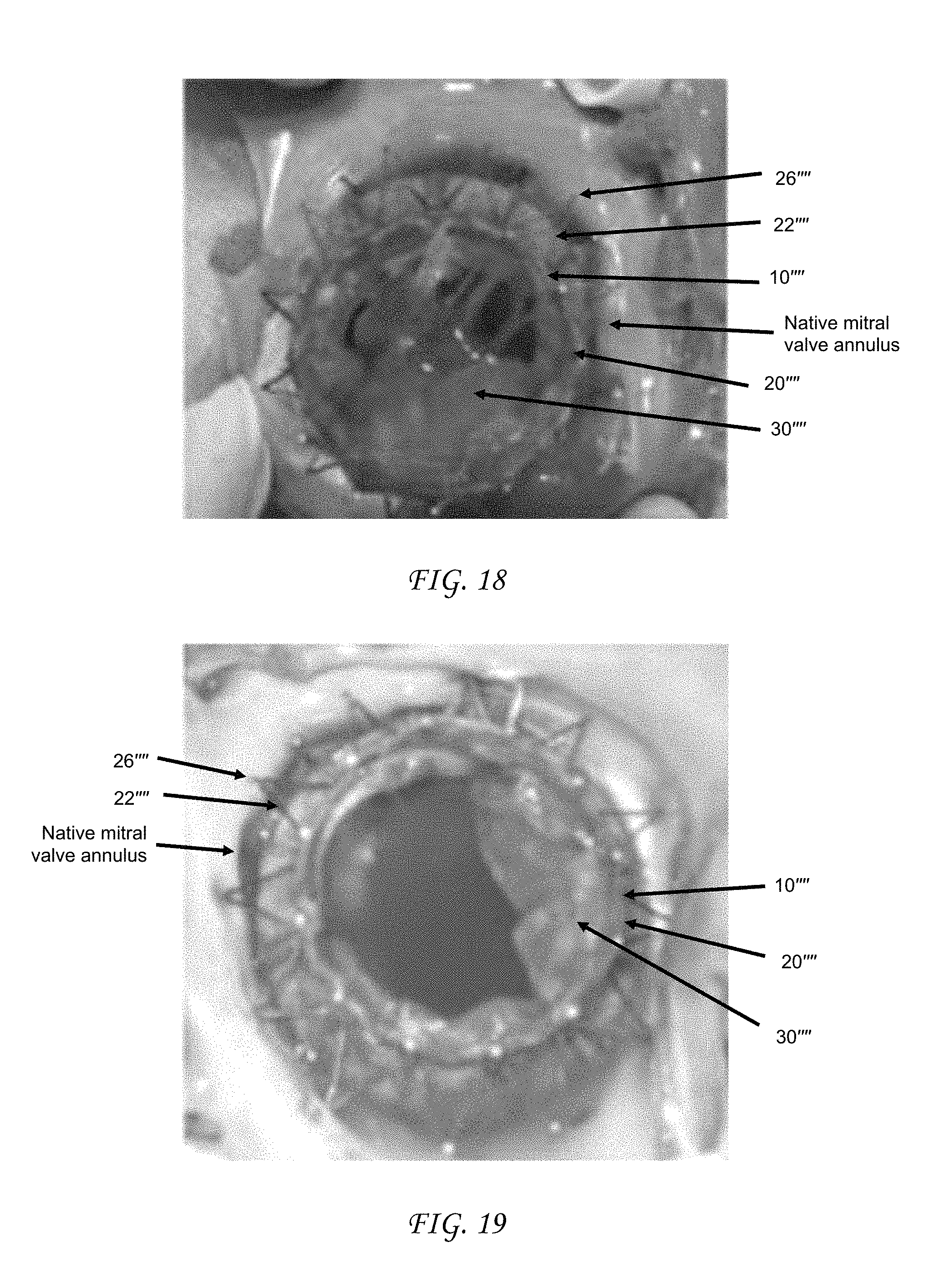
XML
uspto.report is an independent third-party trademark research tool that is not affiliated, endorsed, or sponsored by the United States Patent and Trademark Office (USPTO) or any other governmental organization. The information provided by uspto.report is based on publicly available data at the time of writing and is intended for informational purposes only.
While we strive to provide accurate and up-to-date information, we do not guarantee the accuracy, completeness, reliability, or suitability of the information displayed on this site. The use of this site is at your own risk. Any reliance you place on such information is therefore strictly at your own risk.
All official trademark data, including owner information, should be verified by visiting the official USPTO website at www.uspto.gov. This site is not intended to replace professional legal advice and should not be used as a substitute for consulting with a legal professional who is knowledgeable about trademark law.