System, apparatus and method for automatically verifying exploits within suspect objects and highlighting the display information associated with the verified exploits
Aziz , et al. Nov
U.S. patent number 10,476,909 [Application Number 15/298,159] was granted by the patent office on 2019-11-12 for system, apparatus and method for automatically verifying exploits within suspect objects and highlighting the display information associated with the verified exploits. This patent grant is currently assigned to FireEye, Inc.. The grantee listed for this patent is FireEye, Inc.. Invention is credited to Muhammad Amin, Ashar Aziz, Zheng Bu, Osman Abdoul Ismael.


View All Diagrams
| United States Patent | 10,476,909 |
| Aziz , et al. | November 12, 2019 |
System, apparatus and method for automatically verifying exploits within suspect objects and highlighting the display information associated with the verified exploits
Abstract
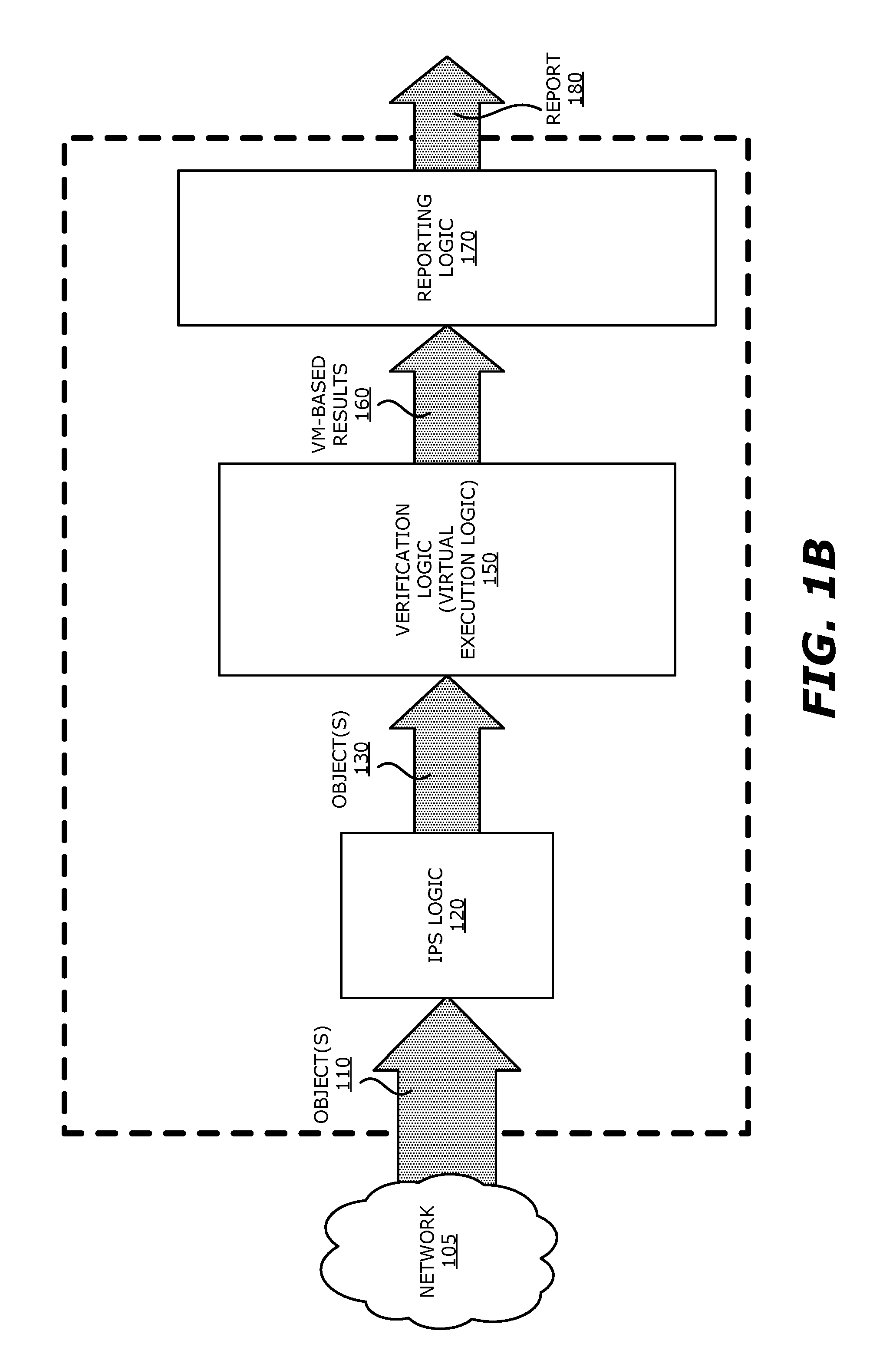
According to one embodiment, a threat detection system comprising an intrusion protection system (IPS) logic, a virtual execution logic and a reporting logic is shown. The IPS logic is configured to receive a first plurality of objects and analyze the first plurality of objects to identify a second plurality of objects as potential exploits, the second plurality of objects being a subset of the first plurality of objects and being lesser or equal in number to the first plurality of objects. The virtual execution logic including at least one virtual machine configured to process content within each of the second plurality of objects and monitor for anomalous behaviors during the processing that are indicative of exploits to classify that a first subset of the second plurality of objects includes one or more verified exploits. The reporting logic configured to provide a display of exploit information associated with the one or more verified exploits.
| Inventors: | Aziz; Ashar (Coral Gables, FL), Amin; Muhammad (Milpitas, CA), Ismael; Osman Abdoul (Palo Alto, CA), Bu; Zheng (Fremont, CA) | ||||||||||
|---|---|---|---|---|---|---|---|---|---|---|---|
| Applicant: |
|
||||||||||
| Assignee: | FireEye, Inc. (Milpitas,
CA) |
||||||||||
| Family ID: | 52395199 | ||||||||||
| Appl. No.: | 15/298,159 | ||||||||||
| Filed: | October 19, 2016 |
Related U.S. Patent Documents
| Application Number | Filing Date | Patent Number | Issue Date | ||
|---|---|---|---|---|---|
| 14228073 | Mar 27, 2014 | 9756074 | |||
| 61921033 | Dec 26, 2013 | ||||
| Current U.S. Class: | 1/1 |
| Current CPC Class: | G06F 21/564 (20130101); H04L 63/1491 (20130101); G06F 21/56 (20130101); G06F 21/53 (20130101); G06F 9/45558 (20130101); G06F 21/566 (20130101); H04L 63/1433 (20130101); H04L 63/1416 (20130101); G06F 2009/45587 (20130101); H04L 63/145 (20130101); G06F 2221/033 (20130101) |
| Current International Class: | G06F 21/56 (20130101); H04L 29/06 (20060101); G06F 9/455 (20180101) |
References Cited [Referenced By]
U.S. Patent Documents
| 4292580 | September 1981 | Ott et al. |
| 5175732 | December 1992 | Hendel et al. |
| 5319776 | June 1994 | Hile et al. |
| 5440723 | August 1995 | Arnold et al. |
| 5490249 | February 1996 | Miller |
| 5657473 | August 1997 | Killean et al. |
| 5802277 | September 1998 | Cowlard |
| 5842002 | November 1998 | Schnurer et al. |
| 5960170 | September 1999 | Chen et al. |
| 5978917 | November 1999 | Chi |
| 5983348 | November 1999 | Ji |
| 6088803 | July 2000 | Tso et al. |
| 6092194 | July 2000 | Touboul |
| 6094677 | July 2000 | Capek et al. |
| 6108799 | August 2000 | Boulay et al. |
| 6118382 | September 2000 | Hibbs et al. |
| 6154844 | November 2000 | Touboul et al. |
| 6269330 | July 2001 | Cidon et al. |
| 6272641 | August 2001 | Ji |
| 6279113 | August 2001 | Vaidya |
| 6298445 | October 2001 | Shostack et al. |
| 6357008 | March 2002 | Nachenberg |
| 6417774 | July 2002 | Hibbs et al. |
| 6424627 | July 2002 | Sorhaug et al. |
| 6442696 | August 2002 | Wray et al. |
| 6484315 | November 2002 | Ziese |
| 6487666 | November 2002 | Shanklin et al. |
| 6493756 | December 2002 | O'Brien et al. |
| 6550012 | April 2003 | Villa et al. |
| 6700497 | March 2004 | Hibbs et al. |
| 6775657 | August 2004 | Baker |
| 6831893 | December 2004 | Ben Nun et al. |
| 6832367 | December 2004 | Choi et al. |
| 6895550 | May 2005 | Kanchirayappa et al. |
| 6898632 | May 2005 | Gordy et al. |
| 6907396 | June 2005 | Muttik et al. |
| 6941348 | September 2005 | Petry et al. |
| 6971097 | November 2005 | Wallman |
| 6981279 | December 2005 | Arnold et al. |
| 6995665 | February 2006 | Appelt et al. |
| 7007107 | February 2006 | Ivchenko et al. |
| 7028179 | April 2006 | Anderson et al. |
| 7043757 | May 2006 | Hoefelmeyer et al. |
| 7058822 | June 2006 | Edery et al. |
| 7069316 | June 2006 | Gryaznov |
| 7080407 | July 2006 | Zhao et al. |
| 7080408 | July 2006 | Pak et al. |
| 7093002 | August 2006 | Wolff et al. |
| 7093239 | August 2006 | van der Made |
| 7096498 | August 2006 | Judge |
| 7100201 | August 2006 | Izatt |
| 7107617 | September 2006 | Hursey et al. |
| 7159149 | January 2007 | Spiegel et al. |
| 7213260 | May 2007 | Judge |
| 7231667 | June 2007 | Jordan |
| 7240364 | July 2007 | Branscomb et al. |
| 7240368 | July 2007 | Roesch et al. |
| 7243371 | July 2007 | Kasper et al. |
| 7249175 | July 2007 | Donaldson |
| 7287278 | October 2007 | Liang |
| 7308716 | December 2007 | Danford et al. |
| 7328453 | February 2008 | Merkle, Jr. et al. |
| 7346486 | March 2008 | Ivancic et al. |
| 7356736 | April 2008 | Natvig |
| 7386888 | June 2008 | Liang et al. |
| 7392542 | June 2008 | Bucher |
| 7418729 | August 2008 | Szor |
| 7428300 | September 2008 | Drew et al. |
| 7437764 | October 2008 | Sobel et al. |
| 7441272 | October 2008 | Durham et al. |
| 7448084 | November 2008 | Apap et al. |
| 7458098 | November 2008 | Judge et al. |
| 7464404 | December 2008 | Carpenter et al. |
| 7464407 | December 2008 | Nakae et al. |
| 7467408 | December 2008 | O'Toole, Jr. |
| 7478428 | January 2009 | Thomlinson |
| 7480773 | January 2009 | Reed |
| 7487543 | February 2009 | Arnold et al. |
| 7496960 | February 2009 | Chen et al. |
| 7496961 | February 2009 | Zimmer et al. |
| 7519990 | April 2009 | Xie |
| 7523493 | April 2009 | Liang et al. |
| 7530104 | May 2009 | Thrower et al. |
| 7540025 | May 2009 | Tzadikario |
| 7546638 | June 2009 | Anderson et al. |
| 7565550 | July 2009 | Liang et al. |
| 7568233 | July 2009 | Szor et al. |
| 7584455 | September 2009 | Ball |
| 7603715 | October 2009 | Costa et al. |
| 7607171 | October 2009 | Marsden et al. |
| 7639714 | December 2009 | Stolfo et al. |
| 7644441 | January 2010 | Schmid et al. |
| 7657419 | February 2010 | van der Made |
| 7676841 | March 2010 | Sobchuk et al. |
| 7698548 | April 2010 | Shelest et al. |
| 7707633 | April 2010 | Danford et al. |
| 7712136 | May 2010 | Sprosts et al. |
| 7730011 | June 2010 | Deninger et al. |
| 7739740 | June 2010 | Nachenberg et al. |
| 7779463 | August 2010 | Stolfo et al. |
| 7784097 | August 2010 | Stolfo et al. |
| 7832008 | November 2010 | Kraemer |
| 7836502 | November 2010 | Zhao et al. |
| 7849506 | December 2010 | Dansey et al. |
| 7854007 | December 2010 | Sprosts et al. |
| 7869073 | January 2011 | Oshima |
| 7877803 | January 2011 | Enstone et al. |
| 7904959 | March 2011 | Sidiroglou et al. |
| 7908660 | March 2011 | Bahl |
| 7930738 | April 2011 | Petersen |
| 7937387 | May 2011 | Frazier et al. |
| 7937761 | May 2011 | Bennett |
| 7949849 | May 2011 | Lowe et al. |
| 7996556 | August 2011 | Raghavan et al. |
| 7996836 | August 2011 | McCorkendale et al. |
| 7996904 | August 2011 | Chiueh et al. |
| 7996905 | August 2011 | Arnold et al. |
| 8006305 | August 2011 | Aziz |
| 8010667 | August 2011 | Zhang et al. |
| 8020206 | September 2011 | Hubbard et al. |
| 8028338 | September 2011 | Schneider et al. |
| 8042184 | October 2011 | Batenin |
| 8045094 | October 2011 | Teragawa |
| 8045458 | October 2011 | Alperovitch et al. |
| 8069484 | November 2011 | McMillan et al. |
| 8087086 | December 2011 | Lai et al. |
| 8171553 | May 2012 | Aziz et al. |
| 8176049 | May 2012 | Deninger et al. |
| 8176480 | May 2012 | Spertus |
| 8201246 | June 2012 | Wu et al. |
| 8204984 | June 2012 | Aziz et al. |
| 8214905 | July 2012 | Doukhvalov et al. |
| 8220055 | July 2012 | Kennedy |
| 8225288 | July 2012 | Miller et al. |
| 8225373 | July 2012 | Kraemer |
| 8233882 | July 2012 | Rogel |
| 8234640 | July 2012 | Fitzgerald et al. |
| 8234709 | July 2012 | Viljoen et al. |
| 8239944 | August 2012 | Nachenberg et al. |
| 8260914 | September 2012 | Ranjan |
| 8266091 | September 2012 | Gubin et al. |
| 8286251 | October 2012 | Eker et al. |
| 8291499 | October 2012 | Aziz et al. |
| 8307435 | November 2012 | Mann et al. |
| 8307443 | November 2012 | Wang et al. |
| 8312545 | November 2012 | Tuvell et al. |
| 8321936 | November 2012 | Green et al. |
| 8321941 | November 2012 | Tuvell et al. |
| 8332571 | December 2012 | Edwards, Sr. |
| 8365286 | January 2013 | Poston |
| 8365297 | January 2013 | Parshin et al. |
| 8370938 | February 2013 | Daswani et al. |
| 8370939 | February 2013 | Zaitsev et al. |
| 8375444 | February 2013 | Aziz et al. |
| 8381299 | February 2013 | Stolfo et al. |
| 8402529 | March 2013 | Green et al. |
| 8464340 | June 2013 | Ahn et al. |
| 8479174 | July 2013 | Chiriac |
| 8479276 | July 2013 | Vaystikh et al. |
| 8479291 | July 2013 | Bodke |
| 8510827 | August 2013 | Leake et al. |
| 8510828 | August 2013 | Guo et al. |
| 8510842 | August 2013 | Amit et al. |
| 8516478 | August 2013 | Edwards et al. |
| 8516590 | August 2013 | Ranadive et al. |
| 8516593 | August 2013 | Aziz |
| 8522348 | August 2013 | Chen et al. |
| 8528086 | September 2013 | Aziz |
| 8533824 | September 2013 | Hutton et al. |
| 8539582 | September 2013 | Aziz et al. |
| 8549638 | October 2013 | Aziz |
| 8555391 | October 2013 | Demir et al. |
| 8561177 | October 2013 | Aziz et al. |
| 8566476 | October 2013 | Shifter et al. |
| 8566946 | October 2013 | Aziz et al. |
| 8584094 | November 2013 | Dadhia et al. |
| 8584234 | November 2013 | Sobel et al. |
| 8584239 | November 2013 | Aziz et al. |
| 8595834 | November 2013 | Xie et al. |
| 8627476 | January 2014 | Satish et al. |
| 8635696 | January 2014 | Aziz |
| 8682054 | March 2014 | Xue et al. |
| 8682812 | March 2014 | Ranjan |
| 8689333 | April 2014 | Aziz |
| 8695096 | April 2014 | Zhang |
| 8713631 | April 2014 | Pavlyushchik |
| 8713681 | April 2014 | Silberman et al. |
| 8726392 | May 2014 | McCorkendale et al. |
| 8739280 | May 2014 | Chess et al. |
| 8776229 | July 2014 | Aziz |
| 8782792 | July 2014 | Bodke |
| 8789172 | July 2014 | Stolfo et al. |
| 8789178 | July 2014 | Kejriwal et al. |
| 8793278 | July 2014 | Frazier et al. |
| 8793787 | July 2014 | Ismael et al. |
| 8805947 | August 2014 | Kuzkin et al. |
| 8806647 | August 2014 | Daswani et al. |
| 8832829 | September 2014 | Manni et al. |
| 8850570 | September 2014 | Ramzan |
| 8850571 | September 2014 | Staniford et al. |
| 8869281 | October 2014 | Call et al. |
| 8881234 | November 2014 | Narasimhan et al. |
| 8881271 | November 2014 | Butler, II |
| 8881282 | November 2014 | Aziz et al. |
| 8898788 | November 2014 | Aziz et al. |
| 8935779 | January 2015 | Manni et al. |
| 8943594 | January 2015 | Arrowood |
| 8949257 | February 2015 | Shifter et al. |
| 8984638 | March 2015 | Aziz et al. |
| 8990939 | March 2015 | Staniford et al. |
| 8990944 | March 2015 | Singh et al. |
| 8997219 | March 2015 | Staniford et al. |
| 9009822 | April 2015 | Ismael et al. |
| 9009823 | April 2015 | Ismael et al. |
| 9027135 | May 2015 | Aziz |
| 9071638 | June 2015 | Aziz et al. |
| 9104867 | August 2015 | Thioux et al. |
| 9106630 | August 2015 | Frazier et al. |
| 9106694 | August 2015 | Aziz et al. |
| 9118715 | August 2015 | Staniford et al. |
| 9158915 | October 2015 | Yumer |
| 9159035 | October 2015 | Ismael et al. |
| 9171160 | October 2015 | Vincent et al. |
| 9176843 | November 2015 | Ismael et al. |
| 9189627 | November 2015 | Islam |
| 9195829 | November 2015 | Goradia et al. |
| 9197664 | November 2015 | Aziz et al. |
| 9223972 | December 2015 | Vincent et al. |
| 9225740 | December 2015 | Ismael et al. |
| 9241010 | January 2016 | Bennett et al. |
| 9251343 | February 2016 | Vincent et al. |
| 9262635 | February 2016 | Paithane et al. |
| 9268936 | February 2016 | Butler |
| 9275229 | March 2016 | LeMasters |
| 9282109 | March 2016 | Aziz et al. |
| 9292686 | March 2016 | Ismael et al. |
| 9294501 | March 2016 | Mesdaq et al. |
| 9300686 | March 2016 | Pidathala et al. |
| 9306960 | April 2016 | Aziz |
| 9306974 | April 2016 | Aziz |
| 9311479 | April 2016 | Manni et al. |
| 9355247 | May 2016 | Thioux et al. |
| 9356944 | May 2016 | Aziz |
| 9363280 | June 2016 | Rivlin et al. |
| 9367681 | June 2016 | Ismael et al. |
| 9398028 | July 2016 | Karandikar et al. |
| 9413781 | August 2016 | Cunningham et al. |
| 9426071 | August 2016 | Caldejon et al. |
| 9430646 | August 2016 | Mushtaq et al. |
| 9432389 | August 2016 | Khalid et al. |
| 9438613 | September 2016 | Paithane et al. |
| 9438622 | September 2016 | Staniford et al. |
| 9438623 | September 2016 | Thioux et al. |
| 9459901 | October 2016 | Jung et al. |
| 9467460 | October 2016 | Otvagin et al. |
| 9483644 | November 2016 | Paithane et al. |
| 9495180 | November 2016 | Ismael |
| 9497213 | November 2016 | Thompson et al. |
| 9507935 | November 2016 | Ismael et al. |
| 9516057 | December 2016 | Aziz |
| 9519782 | December 2016 | Aziz et al. |
| 9536091 | January 2017 | Paithane et al. |
| 9537972 | January 2017 | Edwards et al. |
| 9560059 | January 2017 | Islam |
| 9565202 | February 2017 | Kindlund et al. |
| 9591015 | March 2017 | Amin et al. |
| 9591020 | March 2017 | Aziz |
| 9594903 | March 2017 | L |
| 9594904 | March 2017 | Jain et al. |
| 9594905 | March 2017 | Ismael et al. |
| 9594912 | March 2017 | Thioux et al. |
| 9609007 | March 2017 | Rivlin et al. |
| 9626509 | April 2017 | Khalid et al. |
| 9628498 | April 2017 | Aziz et al. |
| 9628507 | April 2017 | Haq et al. |
| 9633134 | April 2017 | Ross |
| 9635039 | April 2017 | Islam et al. |
| 9641546 | May 2017 | Manni et al. |
| 9654485 | May 2017 | Neumann |
| 9661009 | May 2017 | Karandikar et al. |
| 9661018 | May 2017 | Aziz |
| 9674298 | June 2017 | Edwards et al. |
| 9680861 | June 2017 | Ward |
| 9680862 | June 2017 | Ismael et al. |
| 9690606 | June 2017 | Ha et al. |
| 9690933 | June 2017 | Singh et al. |
| 9690935 | June 2017 | Shiffer et al. |
| 9690936 | June 2017 | Malik et al. |
| 9736179 | August 2017 | Ismael |
| 9740857 | August 2017 | Ismael et al. |
| 9747446 | August 2017 | Pidathala et al. |
| 9756074 | September 2017 | Aziz |
| 9773112 | September 2017 | Rathor et al. |
| 9781144 | October 2017 | Dtvagin et al. |
| 9787700 | October 2017 | Amin et al. |
| 9787706 | October 2017 | Otvagin et al. |
| 9792196 | October 2017 | Ismael et al. |
| 9824209 | November 2017 | Ismael et al. |
| 9824211 | November 2017 | Wilson |
| 9824216 | November 2017 | Khalid et al. |
| 9825976 | November 2017 | Gomez et al. |
| 9825989 | November 2017 | Mehra et al. |
| 9838408 | December 2017 | Karandikar et al. |
| 9838411 | December 2017 | Aziz |
| 9838416 | December 2017 | Aziz |
| 9838417 | December 2017 | Khalid et al. |
| 9846776 | December 2017 | Paithane et al. |
| 9876701 | January 2018 | Caldejon et al. |
| 9888016 | February 2018 | Amin et al. |
| 9888019 | February 2018 | Pidathala et al. |
| 9910988 | March 2018 | Vincent et al. |
| 9912644 | March 2018 | Cunningham |
| 9912681 | March 2018 | Ismael et al. |
| 9912684 | March 2018 | Aziz et al. |
| 9912691 | March 2018 | Mesdaq et al. |
| 9912698 | March 2018 | Thioux et al. |
| 9916440 | March 2018 | Paithane et al. |
| 9921978 | March 2018 | Chan et al. |
| 9934376 | April 2018 | Ismael |
| 9934381 | April 2018 | Kindlund et al. |
| 9946568 | April 2018 | Ismael et al. |
| 9954890 | April 2018 | Staniford et al. |
| 9973531 | May 2018 | Thioux |
| 10002252 | June 2018 | Ismael et al. |
| 10019338 | July 2018 | Goradia et al. |
| 10019573 | July 2018 | Silberman et al. |
| 10025691 | July 2018 | Ismael et al. |
| 10025927 | July 2018 | Khalid et al. |
| 10027689 | July 2018 | Rathor et al. |
| 10027690 | July 2018 | Aziz et al. |
| 10027696 | July 2018 | Rivlin et al. |
| 10033747 | July 2018 | Paithane et al. |
| 10033748 | July 2018 | Cunningham et al. |
| 10033753 | July 2018 | Islam et al. |
| 10033759 | July 2018 | Kabra et al. |
| 10050998 | August 2018 | Singh |
| 10068091 | September 2018 | Aziz et al. |
| 10075455 | September 2018 | Zafar et al. |
| 10083302 | September 2018 | Paithane et al. |
| 10084813 | September 2018 | Eyada |
| 10089461 | October 2018 | Ha et al. |
| 10097573 | October 2018 | Aziz |
| 10104102 | October 2018 | Neumann |
| 10108446 | October 2018 | Steinberg et al. |
| 10121000 | November 2018 | Rivlin et al. |
| 10122746 | November 2018 | Manni et al. |
| 10133863 | November 2018 | Bu et al. |
| 10133866 | November 2018 | Kumar et al. |
| 10146810 | December 2018 | Shiffer et al. |
| 10148693 | December 2018 | Singh et al. |
| 10165000 | December 2018 | Aziz et al. |
| 10169585 | January 2019 | Pilipenko et al. |
| 10176321 | January 2019 | Abbasi et al. |
| 10181029 | January 2019 | Ismael et al. |
| 10191861 | January 2019 | Steinberg et al. |
| 10192052 | January 2019 | Singh et al. |
| 10198574 | February 2019 | Thioux et al. |
| 10200384 | February 2019 | Mushtaq et al. |
| 10210329 | February 2019 | Malik et al. |
| 10216927 | February 2019 | Steinberg |
| 10218740 | February 2019 | Mesdaq et al. |
| 10242185 | March 2019 | Goradia |
| 2001/0005889 | June 2001 | Albrecht |
| 2001/0047326 | November 2001 | Broadbent et al. |
| 2002/0018903 | February 2002 | Kokubo et al. |
| 2002/0038430 | March 2002 | Edwards et al. |
| 2002/0091819 | July 2002 | Melchione et al. |
| 2002/0095607 | July 2002 | Lin-Hendel |
| 2002/0116627 | August 2002 | Tarbotton et al. |
| 2002/0144156 | October 2002 | Copeland |
| 2002/0162015 | October 2002 | Tang |
| 2002/0166063 | November 2002 | Lachman et al. |
| 2002/0169952 | November 2002 | DiSanto et al. |
| 2002/0184528 | December 2002 | Shevenell et al. |
| 2002/0188887 | December 2002 | Largman et al. |
| 2002/0194490 | December 2002 | Halperin et al. |
| 2003/0021728 | January 2003 | Sharpe et al. |
| 2003/0074578 | April 2003 | Ford et al. |
| 2003/0084318 | May 2003 | Schertz |
| 2003/0101381 | May 2003 | Mateev et al. |
| 2003/0115483 | June 2003 | Liang |
| 2003/0188190 | October 2003 | Aaron et al. |
| 2003/0191957 | October 2003 | Hypponen et al. |
| 2003/0200460 | October 2003 | Morota et al. |
| 2003/0212902 | November 2003 | van der Made |
| 2003/0229801 | December 2003 | Kouznetsov et al. |
| 2003/0237000 | December 2003 | Denton et al. |
| 2004/0003323 | January 2004 | Bennett et al. |
| 2004/0006473 | January 2004 | Mills et al. |
| 2004/0015712 | January 2004 | Szor |
| 2004/0019832 | January 2004 | Arnold et al. |
| 2004/0047356 | March 2004 | Bauer |
| 2004/0083408 | April 2004 | Spiegel et al. |
| 2004/0088581 | May 2004 | Brawn et al. |
| 2004/0093513 | May 2004 | Cantrell et al. |
| 2004/0111531 | June 2004 | Staniford et al. |
| 2004/0117478 | June 2004 | Triulzi et al. |
| 2004/0117624 | June 2004 | Brandt et al. |
| 2004/0128355 | July 2004 | Chao et al. |
| 2004/0165588 | August 2004 | Pandya |
| 2004/0236963 | November 2004 | Danford et al. |
| 2004/0243349 | December 2004 | Greifeneder et al. |
| 2004/0249911 | December 2004 | Alkhatib et al. |
| 2004/0255161 | December 2004 | Cavanaugh |
| 2004/0268147 | December 2004 | Wiederin et al. |
| 2005/0005159 | January 2005 | Oliphant |
| 2005/0021740 | January 2005 | Bar et al. |
| 2005/0033960 | February 2005 | Vialen et al. |
| 2005/0033989 | February 2005 | Poletto et al. |
| 2005/0050148 | March 2005 | Mohammadioun et al. |
| 2005/0086523 | April 2005 | Zimmer et al. |
| 2005/0091513 | April 2005 | Mitomo et al. |
| 2005/0091533 | April 2005 | Omote et al. |
| 2005/0091652 | April 2005 | Ross et al. |
| 2005/0108562 | May 2005 | Khazan et al. |
| 2005/0114663 | May 2005 | Cornell et al. |
| 2005/0125195 | June 2005 | Brendel |
| 2005/0149726 | July 2005 | Joshi et al. |
| 2005/0157662 | July 2005 | Bingham et al. |
| 2005/0183143 | August 2005 | Anderholm et al. |
| 2005/0201297 | September 2005 | Peikari |
| 2005/0210533 | September 2005 | Copeland et al. |
| 2005/0238005 | October 2005 | Chen et al. |
| 2005/0240781 | October 2005 | Gassoway |
| 2005/0262562 | November 2005 | Gassoway |
| 2005/0265331 | December 2005 | Stolfo |
| 2005/0273856 | December 2005 | Huddleston |
| 2005/0283839 | December 2005 | Cowburn |
| 2006/0010495 | January 2006 | Cohen et al. |
| 2006/0015416 | January 2006 | Hoffman et al. |
| 2006/0015715 | January 2006 | Anderson |
| 2006/0015747 | January 2006 | Van de Ven |
| 2006/0021029 | January 2006 | Brickell et al. |
| 2006/0021054 | January 2006 | Costa et al. |
| 2006/0031476 | February 2006 | Mathes et al. |
| 2006/0047665 | March 2006 | Neil |
| 2006/0070130 | March 2006 | Costea et al. |
| 2006/0075496 | April 2006 | Carpenter et al. |
| 2006/0095968 | May 2006 | Portolani et al. |
| 2006/0101516 | May 2006 | Sudaharan et al. |
| 2006/0101517 | May 2006 | Banzhof et al. |
| 2006/0117385 | June 2006 | Mester et al. |
| 2006/0123477 | June 2006 | Raghavan et al. |
| 2006/0143709 | June 2006 | Brooks et al. |
| 2006/0150249 | July 2006 | Gassen et al. |
| 2006/0161983 | July 2006 | Cothrell et al. |
| 2006/0161987 | July 2006 | Levy-Yurista |
| 2006/0161989 | July 2006 | Reshef et al. |
| 2006/0164199 | July 2006 | Gilde et al. |
| 2006/0173992 | August 2006 | Weber et al. |
| 2006/0179147 | August 2006 | Tran et al. |
| 2006/0184632 | August 2006 | Marino et al. |
| 2006/0191010 | August 2006 | Benjamin |
| 2006/0221956 | October 2006 | Narayan et al. |
| 2006/0236393 | October 2006 | Kramer et al. |
| 2006/0242709 | October 2006 | Seinfeld et al. |
| 2006/0248519 | November 2006 | Jaeger et al. |
| 2006/0248582 | November 2006 | Panjwani et al. |
| 2006/0251104 | November 2006 | Koga |
| 2006/0288417 | December 2006 | Bookbinder et al. |
| 2007/0006288 | January 2007 | Mayfield et al. |
| 2007/0006313 | January 2007 | Porras et al. |
| 2007/0011174 | January 2007 | Takaragi et al. |
| 2007/0016951 | January 2007 | Piccard et al. |
| 2007/0019286 | January 2007 | Kikuchi |
| 2007/0033645 | February 2007 | Jones |
| 2007/0038943 | February 2007 | FitzGerald et al. |
| 2007/0064689 | March 2007 | Shin et al. |
| 2007/0074169 | March 2007 | Chess et al. |
| 2007/0094730 | April 2007 | Bhikkaji et al. |
| 2007/0094731 | April 2007 | Teodosiu |
| 2007/0101435 | May 2007 | Konanka et al. |
| 2007/0128855 | June 2007 | Cho et al. |
| 2007/0142030 | June 2007 | Sinha et al. |
| 2007/0143827 | June 2007 | Nicodemus et al. |
| 2007/0156895 | July 2007 | Vuong |
| 2007/0157180 | July 2007 | Tillmann et al. |
| 2007/0157306 | July 2007 | Elrod et al. |
| 2007/0168988 | July 2007 | Eisner et al. |
| 2007/0171824 | July 2007 | Ruello et al. |
| 2007/0174915 | July 2007 | Gribble et al. |
| 2007/0192500 | August 2007 | Lum |
| 2007/0192858 | August 2007 | Lum |
| 2007/0198275 | August 2007 | Malden et al. |
| 2007/0208822 | September 2007 | Wang et al. |
| 2007/0220607 | September 2007 | Sprosts et al. |
| 2007/0240218 | October 2007 | Tuvell et al. |
| 2007/0240219 | October 2007 | Tuvell et al. |
| 2007/0240220 | October 2007 | Tuvell et al. |
| 2007/0240222 | October 2007 | Tuvell et al. |
| 2007/0250930 | October 2007 | Aziz et al. |
| 2007/0256132 | November 2007 | Oliphant |
| 2007/0271446 | November 2007 | Nakamura |
| 2008/0005782 | January 2008 | Aziz |
| 2008/0016208 | January 2008 | Treinen |
| 2008/0018122 | January 2008 | Zierler et al. |
| 2008/0028463 | January 2008 | Dagon et al. |
| 2008/0032556 | February 2008 | Schreier |
| 2008/0040710 | February 2008 | Chiriac |
| 2008/0046781 | February 2008 | Childs et al. |
| 2008/0066179 | March 2008 | Liu |
| 2008/0072326 | March 2008 | Danford et al. |
| 2008/0077793 | March 2008 | Tan et al. |
| 2008/0080518 | April 2008 | Hoeflin et al. |
| 2008/0086720 | April 2008 | Lekel |
| 2008/0098476 | April 2008 | Syversen |
| 2008/0120722 | May 2008 | Sima et al. |
| 2008/0134178 | June 2008 | Fitzgerald et al. |
| 2008/0134334 | June 2008 | Kim et al. |
| 2008/0141376 | June 2008 | Clausen et al. |
| 2008/0184367 | July 2008 | McMillan et al. |
| 2008/0184373 | July 2008 | Traut et al. |
| 2008/0189787 | August 2008 | Arnold et al. |
| 2008/0201778 | August 2008 | Guo et al. |
| 2008/0209557 | August 2008 | Herley et al. |
| 2008/0215742 | September 2008 | Goldszmidt et al. |
| 2008/0222729 | September 2008 | Chen et al. |
| 2008/0263665 | October 2008 | Ma et al. |
| 2008/0295172 | November 2008 | Bohacek |
| 2008/0301810 | December 2008 | Lehane et al. |
| 2008/0307524 | December 2008 | Singh et al. |
| 2008/0313738 | December 2008 | Enderby |
| 2008/0320594 | December 2008 | Jiang |
| 2009/0003317 | January 2009 | Kasralikar et al. |
| 2009/0007100 | January 2009 | Field et al. |
| 2009/0013408 | January 2009 | Schipka |
| 2009/0031423 | January 2009 | Liu et al. |
| 2009/0036111 | February 2009 | Danford et al. |
| 2009/0037835 | February 2009 | Goldman |
| 2009/0044024 | February 2009 | Oberheide et al. |
| 2009/0044274 | February 2009 | Budko et al. |
| 2009/0064332 | March 2009 | Porras et al. |
| 2009/0077666 | March 2009 | Chen et al. |
| 2009/0083369 | March 2009 | Marmor |
| 2009/0083855 | March 2009 | Apap et al. |
| 2009/0089879 | April 2009 | Wang et al. |
| 2009/0094697 | April 2009 | Provos et al. |
| 2009/0113425 | April 2009 | Ports et al. |
| 2009/0125976 | May 2009 | Wassermann et al. |
| 2009/0126015 | May 2009 | Monastyrsky et al. |
| 2009/0126016 | May 2009 | Sobko et al. |
| 2009/0133125 | May 2009 | Choi et al. |
| 2009/0144823 | June 2009 | Lamastra et al. |
| 2009/0158430 | June 2009 | Borders |
| 2009/0172815 | July 2009 | Gu et al. |
| 2009/0187992 | July 2009 | Poston |
| 2009/0193293 | July 2009 | Stolfo et al. |
| 2009/0198651 | August 2009 | Shiffer et al. |
| 2009/0198670 | August 2009 | Shiffer et al. |
| 2009/0198689 | August 2009 | Frazier et al. |
| 2009/0199274 | August 2009 | Frazier et al. |
| 2009/0199296 | August 2009 | Xie et al. |
| 2009/0228233 | September 2009 | Anderson et al. |
| 2009/0241187 | September 2009 | Troyansky |
| 2009/0241190 | September 2009 | Todd et al. |
| 2009/0265692 | October 2009 | Godefroid et al. |
| 2009/0271867 | October 2009 | Zhang |
| 2009/0300415 | December 2009 | Zhang et al. |
| 2009/0300761 | December 2009 | Park et al. |
| 2009/0320136 | December 2009 | Lambert |
| 2009/0328185 | December 2009 | Berg et al. |
| 2009/0328221 | December 2009 | Blumfield et al. |
| 2010/0005146 | January 2010 | Drako et al. |
| 2010/0011205 | January 2010 | McKenna |
| 2010/0017546 | January 2010 | Poo et al. |
| 2010/0030996 | February 2010 | Butler, II |
| 2010/0031353 | February 2010 | Thomas et al. |
| 2010/0037314 | February 2010 | Perdisci et al. |
| 2010/0043073 | February 2010 | Kuwamura |
| 2010/0054278 | March 2010 | Stolfo et al. |
| 2010/0058470 | March 2010 | Kim |
| 2010/0058474 | March 2010 | Hicks |
| 2010/0064044 | March 2010 | Nonoyama |
| 2010/0077481 | March 2010 | Polyakov et al. |
| 2010/0083376 | April 2010 | Pereira et al. |
| 2010/0115621 | May 2010 | Staniford |
| 2010/0128862 | May 2010 | Vendrow |
| 2010/0132038 | May 2010 | Zaitsev |
| 2010/0154056 | June 2010 | Smith et al. |
| 2010/0180344 | July 2010 | Malyshev et al. |
| 2010/0192223 | July 2010 | Ismael et al. |
| 2010/0220863 | September 2010 | Dupaquis et al. |
| 2010/0235831 | September 2010 | Dittmer |
| 2010/0251104 | September 2010 | Massand |
| 2010/0281102 | November 2010 | Chinta et al. |
| 2010/0281541 | November 2010 | Stolfo et al. |
| 2010/0281542 | November 2010 | Stolfo et al. |
| 2010/0287260 | November 2010 | Peterson et al. |
| 2010/0287613 | November 2010 | Singh et al. |
| 2010/0299754 | November 2010 | Amit et al. |
| 2010/0306173 | December 2010 | Frank |
| 2011/0004737 | January 2011 | Greenebaum |
| 2011/0025504 | February 2011 | Lyon et al. |
| 2011/0041179 | February 2011 | St Hlberg |
| 2011/0047594 | February 2011 | Mahaffey et al. |
| 2011/0047620 | February 2011 | Mahaffey et al. |
| 2011/0055907 | March 2011 | Narasimhan et al. |
| 2011/0078794 | March 2011 | Manni et al. |
| 2011/0093951 | April 2011 | Aziz |
| 2011/0099620 | April 2011 | Stavrou et al. |
| 2011/0099633 | April 2011 | Aziz |
| 2011/0099635 | April 2011 | Silberman et al. |
| 2011/0113231 | May 2011 | Kaminsky |
| 2011/0145918 | June 2011 | Jung et al. |
| 2011/0145920 | June 2011 | Mahaffey et al. |
| 2011/0145934 | June 2011 | Abramovici et al. |
| 2011/0167493 | July 2011 | Song et al. |
| 2011/0167494 | July 2011 | Bowen et al. |
| 2011/0173213 | July 2011 | Frazier et al. |
| 2011/0173460 | July 2011 | Ito et al. |
| 2011/0219449 | September 2011 | St. Neitzel et al. |
| 2011/0219450 | September 2011 | McDougal et al. |
| 2011/0225624 | September 2011 | Sawhney et al. |
| 2011/0225655 | September 2011 | Niemela et al. |
| 2011/0247072 | October 2011 | Staniford et al. |
| 2011/0265182 | October 2011 | Peinado et al. |
| 2011/0289582 | November 2011 | Kejriwal et al. |
| 2011/0302587 | December 2011 | Nishikawa et al. |
| 2011/0307954 | December 2011 | Melnik et al. |
| 2011/0307955 | December 2011 | Kaplan et al. |
| 2011/0307956 | December 2011 | Yermakov et al. |
| 2011/0314546 | December 2011 | Aziz et al. |
| 2011/0321166 | December 2011 | Capalik et al. |
| 2012/0023593 | January 2012 | Puder et al. |
| 2012/0054869 | March 2012 | Yen et al. |
| 2012/0066698 | March 2012 | Yanoo |
| 2012/0079596 | March 2012 | Thomas et al. |
| 2012/0084859 | April 2012 | Radinsky et al. |
| 2012/0096553 | April 2012 | Srivastava et al. |
| 2012/0110667 | May 2012 | Zubrilin et al. |
| 2012/0117652 | May 2012 | Manni et al. |
| 2012/0121154 | May 2012 | Xue et al. |
| 2012/0124426 | May 2012 | Maybee et al. |
| 2012/0174186 | July 2012 | Aziz et al. |
| 2012/0174196 | July 2012 | Bhogavilli et al. |
| 2012/0174218 | July 2012 | McCoy et al. |
| 2012/0198279 | August 2012 | Schroeder |
| 2012/0210423 | August 2012 | Friedrichs et al. |
| 2012/0222121 | August 2012 | Staniford et al. |
| 2012/0255015 | October 2012 | Sahita et al. |
| 2012/0255017 | October 2012 | Sallam |
| 2012/0260342 | October 2012 | Dube et al. |
| 2012/0266244 | October 2012 | Green et al. |
| 2012/0278886 | November 2012 | Luna |
| 2012/0278889 | November 2012 | El-Moussa |
| 2012/0297489 | November 2012 | Dequevy |
| 2012/0330801 | December 2012 | McDougal et al. |
| 2012/0331553 | December 2012 | Aziz et al. |
| 2013/0014259 | January 2013 | Gribble et al. |
| 2013/0036472 | February 2013 | Aziz |
| 2013/0047257 | February 2013 | Aziz |
| 2013/0074185 | March 2013 | McDougal et al. |
| 2013/0086684 | April 2013 | Mohler |
| 2013/0091570 | April 2013 | McCorkendale et al. |
| 2013/0097699 | April 2013 | Balupari et al. |
| 2013/0097706 | April 2013 | Titonis et al. |
| 2013/0111587 | May 2013 | Goel et al. |
| 2013/0111591 | May 2013 | Topan |
| 2013/0117849 | May 2013 | Golshan |
| 2013/0117852 | May 2013 | Stute |
| 2013/0117855 | May 2013 | Kim et al. |
| 2013/0139264 | May 2013 | Brinkley et al. |
| 2013/0160125 | June 2013 | Likhachev et al. |
| 2013/0160127 | June 2013 | Jeong et al. |
| 2013/0160130 | June 2013 | Mendelev et al. |
| 2013/0160131 | June 2013 | Madou et al. |
| 2013/0167236 | June 2013 | Sick |
| 2013/0174214 | July 2013 | Duncan |
| 2013/0185789 | July 2013 | Hagiwara et al. |
| 2013/0185795 | July 2013 | Winn et al. |
| 2013/0185798 | July 2013 | Saunders et al. |
| 2013/0191915 | July 2013 | Antonakakis et al. |
| 2013/0196649 | August 2013 | Paddon et al. |
| 2013/0227691 | August 2013 | Aziz et al. |
| 2013/0246370 | September 2013 | Bartram et al. |
| 2013/0247186 | September 2013 | LeMasters |
| 2013/0263260 | October 2013 | Mahaffey et al. |
| 2013/0291109 | October 2013 | Staniford et al. |
| 2013/0298243 | November 2013 | Kumar et al. |
| 2013/0318038 | November 2013 | Shiffer et al. |
| 2013/0318073 | November 2013 | Shiffer et al. |
| 2013/0325791 | December 2013 | Shiffer et al. |
| 2013/0325792 | December 2013 | Shiffer et al. |
| 2013/0325871 | December 2013 | Shiffer et al. |
| 2013/0325872 | December 2013 | Shiffer et al. |
| 2014/0032875 | January 2014 | Butler |
| 2014/0053260 | February 2014 | Gupta et al. |
| 2014/0053261 | February 2014 | Gupta et al. |
| 2014/0068775 | March 2014 | Ward et al. |
| 2014/0082733 | March 2014 | Benefield |
| 2014/0130158 | May 2014 | Wang et al. |
| 2014/0137180 | May 2014 | Lukacs et al. |
| 2014/0169762 | June 2014 | Ryu |
| 2014/0173739 | June 2014 | Ahuja et al. |
| 2014/0179360 | June 2014 | Jackson et al. |
| 2014/0181131 | June 2014 | Ross |
| 2014/0189687 | July 2014 | Jung et al. |
| 2014/0189866 | July 2014 | Shiffer et al. |
| 2014/0189882 | July 2014 | Jung et al. |
| 2014/0237600 | August 2014 | Silberman et al. |
| 2014/0280245 | September 2014 | Wilson |
| 2014/0283037 | September 2014 | Sikorski et al. |
| 2014/0283063 | September 2014 | Thompson et al. |
| 2014/0328204 | November 2014 | Klotsche et al. |
| 2014/0337836 | November 2014 | Ismael |
| 2014/0344926 | November 2014 | Cunningham et al. |
| 2014/0351810 | November 2014 | Pratt |
| 2014/0351935 | November 2014 | Shao et al. |
| 2014/0380473 | December 2014 | Bu et al. |
| 2014/0380474 | December 2014 | Paithane et al. |
| 2015/0007312 | January 2015 | Pidathala et al. |
| 2015/0089647 | March 2015 | Palumbo et al. |
| 2015/0096022 | April 2015 | Vincent et al. |
| 2015/0096023 | April 2015 | Mesdaq et al. |
| 2015/0096024 | April 2015 | Haq et al. |
| 2015/0096025 | April 2015 | Ismael |
| 2015/0121526 | April 2015 | McLarnon |
| 2015/0135317 | May 2015 | Tock et al. |
| 2015/0180886 | June 2015 | Staniford et al. |
| 2015/0186645 | July 2015 | Aziz et al. |
| 2015/0199513 | July 2015 | Ismael et al. |
| 2015/0199531 | July 2015 | Ismael et al. |
| 2015/0199532 | July 2015 | Ismael et al. |
| 2015/0220735 | August 2015 | Paithane et al. |
| 2015/0244732 | August 2015 | Golshan et al. |
| 2015/0372980 | December 2015 | Eyada |
| 2016/0004869 | January 2016 | Ismael et al. |
| 2016/0006756 | January 2016 | Ismael et al. |
| 2016/0044000 | February 2016 | Cunningham |
| 2016/0127393 | May 2016 | Aziz et al. |
| 2016/0191547 | June 2016 | Zafar et al. |
| 2016/0191550 | June 2016 | Ismael et al. |
| 2016/0261612 | September 2016 | Mesdaq et al. |
| 2016/0285914 | September 2016 | Singh et al. |
| 2016/0301703 | October 2016 | Aziz |
| 2016/0335110 | November 2016 | Paithane et al. |
| 2017/0083703 | March 2017 | Abbasi et al. |
| 2018/0013770 | January 2018 | Ismael |
| 2018/0048660 | February 2018 | Paithane et al. |
| 2018/0121316 | May 2018 | Ismael et al. |
| 2018/0288077 | October 2018 | Siddiqui et al. |
| 2106085 | Sep 2009 | EP | |||
| 2439806 | Jan 2008 | GB | |||
| 2490431 | Oct 2012 | GB | |||
| 2518636 | Mar 2016 | GB | |||
| 02/23805 | Mar 2002 | WO | |||
| 02/006928 | Aug 2003 | WO | |||
| 0206928 | Nov 2003 | WO | |||
| 2007117636 | Oct 2007 | WO | |||
| 2008041950 | Apr 2008 | WO | |||
| 2011084431 | Jul 2011 | WO | |||
| 2011/112348 | Sep 2011 | WO | |||
| 2012/075336 | Jun 2012 | WO | |||
| 2012145066 | Oct 2012 | WO | |||
| 2013/067505 | May 2013 | WO | |||
Other References
|
Vomel et al., "Visualizing Indicators of Rootkit Infections in Memory Forensics", pp. 122-139 (Year: 2013). cited by examiner . Marchette, David J., "Computer Intrusion Detection and Network Monitoring: A Statistical Viewpoint", ("Marchette"), (2001). cited by applicant . Margolis, P.E. , "Random House Webster's `Computer & Internet Dictionary 3rd Edition`", ISBN 0375703519, (Dec. 1998). cited by applicant . Moore, D. , et al., "Internet Quarantine: Requirements for Containing Self-Propagating Code", Infocom, vol. 3, (Mar. 30-Apr. 3, 2003), pp. 1901-1910. cited by applicant . Morales, Jose A., et al., ""Analyzing and exploiting network behaviors of malware."", Security and Privacy in Communication Networks. Springer Berlin Heidelberg, 2010. 20-34. cited by applicant . Mori, Detecting Unknown Computer Viruses, 2004, Springer-Verlag Berlin Heidelberg. cited by applicant . Natvig, Kurt , "SANDBOXII: Internet", Virus Bulletin Conference, ("Natvig"), (Sep. 2002). cited by applicant . NetBIOS Working Group. Protocol Standard for a NetBIOS Service on a TCP/UDP transport: Concepts and Methods. STD 19, RFC 1001, Mar. 1987. cited by applicant . Newsome, J. , et al., "Dynamic Taint Analysis for Automatic Detection, Analysis, and Signature Generation of Exploits on Commodity Software", In Proceedings of the 12th Annual Network and Distributed System Security, Symposium (NDSS '05), (Feb. 2005). cited by applicant . Newsome, J. , et al., "Polygraph: Automatically Generating Signatures for Polymorphic Worms", In Proceedings of the IEEE Symposium on Security and Privacy, (May 2005). cited by applicant . Nojiri, D. , et al., "Cooperation Response Strategies for Large Scale Attack Mitigation", DARPA Information Survivability Conference and Exposition, vol. 1, (Apr. 22-24, 2003), pp. 293-302. cited by applicant . Oberheide et al., CloudAV.sub.--N-Version Antivirus in the Network Cloud, 17th USENIX Security Symposium USENIX Security '08 Jul. 28-Aug. 1, 2008 San Jose, CA. cited by applicant . PCT/US2014/072292 filed Dec. 23, 2014 International Preliminary Report dated Jul. 7, 2016. cited by applicant . PCT/US2014/072292 filed Dec. 23, 2014 International Search Report and Written Opinion dated Feb. 23, 2015. cited by applicant . PCT/US2015/037245 filed Jun. 23, 2015 International Search Report and Written Opinion dated Sep. 17, 2015. cited by applicant . Reiner Sailer, Enriquillo Valdez, Trent Jaeger, Roonald Perez, Leendert van Doorn, John Linwood Griffin, Stefan Berger., sHype: Secure Hypervisor Appraoch to Trusted Virtualized Systems (Feb. 2, 2005) ("Sailer"). cited by applicant . Silicon Defense, "Worm Containment in the Internal Network", (Mar. 2003), pp. 1-25. cited by applicant . Singh, S. , et al., "Automated Worm Fingerprinting", Proceedings of the ACM/USENIX Symposium on Operating System Design and Implementation, San Francisco, California, (Dec. 2004). cited by applicant . Spitzner, Lance , "Honeypots: Tracking Hackers", ("Spizner"), (Sep. 17, 2002). cited by applicant . The Sniffers's Guide to Raw Traffic available at: yuba.stanford.edu/.about.casado/pcap/section1.html, (Jan. 6, 2014). cited by applicant . Thomas H. Ptacek, and Timothy N. Newsham , "Insertion, Evasion, and Denial of Service: Eluding Network Intrusion Detection", Secure Networks, ("Ptacek"), (Jan. 1998). cited by applicant . U.S. Appl. No. 14/228,073, filed Mar. 27, 2014 Final Office Action dated Nov. 13, 2015. cited by applicant . U.S. Appl. No. 14/228,073, filed Mar. 27, 2014 Final Office Action dated Nov. 4, 2016. cited by applicant . U.S. Appl. No. 14/228,073, filed Mar. 27, 2014 Non-Final Office Action dated Jun. 15, 2015. cited by applicant . U.S. Appl. No. 14/228,073, filed Mar. 27, 2014 Non-Final Office Action dated Jun. 9, 2016. cited by applicant . U.S. Appl. No. 14/313,934, filed Jun. 24, 2014 Non-Final Office Action dated Sep. 30, 2015. cited by applicant . U.S. Appl. No. 14/620,055, filed Feb. 11, 2015 Non-Final Office Action dated Jun. 15, 2015. cited by applicant . U.S. Pat. No. 8,171,553 filed Apr. 20, 2006, Inter Parties Review Decision dated Jul. 10, 2015. cited by applicant . U.S. Pat. No. 8,291,499 filed Mar. 16, 2012, Inter Parties Review Decision dated Jul. 10, 2015. cited by applicant . Venezia, Paul , "NetDetector Captures Intrusions", InfoWorld Issue 27, ("Venezia"), (Jul. 14, 2003). cited by applicant . Wahid et al., Characterising the Evolution in Scanning Activity of Suspicious Hosts, Oct. 2009, Third International Conference on Network and System Security, pp. 344-350. cited by applicant . Whyte, et al., "DNS-Based Detection of Scanning Works in an Enterprise Network", Proceedings of the 12th Annual Network and Distributed System Security Symposium, (Feb. 2005), 15 pages. cited by applicant . Williamson, Matthew M., "Throttling Viruses: Restricting Propagation to Defeat Malicious Mobile Code", ACSAC Conference, Las Vegas, NV, USA, (Dec. 2002), pp. 1-9. cited by applicant . Yuhei Kawakoya et al: "Memory behavior-based automatic malware unpacking in stealth debugging environment", Malicious and Unwanted Software (Malware), 2010 5th International Conference on, IEEE, Piscataway, NJ, USA, Oct. 19, 2010, pp. 39-46, XP031833827, ISBN:978-1-4244-8-9353-1. cited by applicant . Zhang et al., The Effects of Threading, Infection Time, and Multiple-Attacker Collaboration on Malware Propagation, Sep. 2009, IEEE 28th International Symposium on Reliable Distributed Systems, pp. 73-82. cited by applicant . EP 15810978.5 filed Jan. 24, 2017 Supplementary European Search Report dated Dec. 18, 2017. cited by applicant . JP 2016-561597 filed Jun. 27, 2016 Notice of Allowance dated Oct. 23, 2018. cited by applicant . Paolo Palumbo, Distributed Sample Anaylsis, GB 1317085.7, Sep. 26, 2013. cited by applicant . U.S. Appl. No. 14/313,934, filed Jun. 24, 2014 Final Office Action dated Apr. 22, 2016. cited by applicant . U.S. Appl. No. 14/313,934, filed Jun. 24, 2014 Final Office Action dated Mar. 22, 2017. cited by applicant . U.S. Appl. No. 14/313,934, filed Jun. 24, 2014 Non-Final Office Action dated Nov. 2, 2017. cited by applicant . U.S. Appl. No. 14/313,934, filed Jun. 24, 2014 Non-Final Office Action dated Sep. 23, 2016. cited by applicant . U.S. Appl. No. 14/313,934, filed Jun. 24, 2014 Notice of Allowance dated May 22, 2018. cited by applicant . "Network Security: NetDetector--Network Intrusion Forensic System (NIFS) Whitepaper", ("NetDetector Whitepaper"), (2003). cited by applicant . "Packet", Microsoft Computer Dictionary, Microsoft Press, (Mar. 2002), 1 page. cited by applicant . "When Virtual is Better Than Real", IEEEXplore Digital Library, available at, http://ieeexplore.ieee.org/xpl/articleDetails.sp?reload=true&arnumbe- r=990073, (Dec. 7, 2013). cited by applicant . Abdullah, et al., Visualizing Network Data for Intrusion Detection, 2005 IEEE Workshop on Information Assurance and Security, pp. 100-108. cited by applicant . Adetoye, Adedayo , et al., "Network Intrusion Detection & Response System", ("Adetoye"), (Sep. 2003). cited by applicant . Adobe Systems Incorporated, "PDF 32000-1:2008, Document management--Portable document format--Part1:PDF 1.7", First Edition, Jul. 1, 2008, 756 pages. cited by applicant . AltaVista Advanced Search Results. "attack vector identifier". Http://www.altavista.com/web/results?Itag=ody&pg=aq&aqmode=aqa=Event+Orch- - estrator . . . , (Accessed on Sep. 15, 2009). cited by applicant . AltaVista Advanced Search Results. "Event Orchestrator". Http://www.altavista.com/web/results?Itag=ody&pg=aq&aqmode=aqa=Event+Orch- - esrator . . . , (Accessed on Sep. 3, 2009). cited by applicant . Apostolopoulos, George; hassapis, Constantinos; "V-eM: A cluster of Virtual Machines for Robust, Detailed, and High-Performance Network Emulation", 14th IEEE International Symposium on Modeling, Analysis, and Simulation of Computer and Telecommunication Systems, Sep. 11-14, 2006, pp. 117-126. cited by applicant . Aura, Tuomas, "Scanning electronic documents for personally identifiable information", Proceedings of the 5th ACM workshop on Privacy in electronic society. ACM, 2006. cited by applicant . Baecher, "The Nepenthes Platform: An Efficient Approach to collect Malware", Springer-verlag Berlin Heidelberg, (2006), pp. 165-184. cited by applicant . Baldi, Mario; Risso, Fulvio; "A Framework for Rapid Development and Portable Execution of Packet-Handling Applications", 5th IEEE International Symposium Processing and Information Technology, Dec. 21, 2005, pp. 233-238. cited by applicant . Bayer, et al., "Dynamic Analysis of Malicious Code", J Comput Virol, Springer-Verlag, France., (2006), pp. 67-77. cited by applicant . Boubalos, Chris , "Extracting syslog data out of raw pcap dumps, seclists.org, Honeypots mailing list archives", available at http://seclists.org/honeypots/2003/q2/319 ("Boubalos"), (Jun. 5, 2003). cited by applicant . Chaudet, C. , et al., "Optimal Positioning of Active and Passive Monitoring Devices", International Conference on Emerging Networking Experiments and Technologies, Proceedings of the 2005 ACM Conference on Emerging Network Experiment and Technology, CoNEXT '05, Toulousse, France, (Oct. 2005), pp. 71-82. cited by applicant . Chen, P. M. and Noble, B. D., "When Virtual is Better Than Real, Department of Electrical Engineering and Computer Science", University of Michigan ("Chen") (2001). cited by applicant . Cisco "Intrusion Prevention for the Cisco ASA 5500-x Series" Data Sheet (2012). cited by applicant . Cisco, Configuring the Catalyst Switched Port Analyzer (SPAN) ("Cisco"), (1992). cited by applicant . Clark, John, Sylvian Leblanc,and Scott Knight. "Risks associated with usb hardware trojan devices used by insiders." Systems Conference (SysCon), 2011 IEEE International. IEEE, 2011. cited by applicant . Cohen, M.I. , "PyFlag--An advanced network forensic framework", Digital investigation 5, Elsevier, (2008), pp. S112-S120. cited by applicant . Costa, M. , et al., "Vigilante: End-to-End Containment of Internet Worms", SOSP '05, Association for Computing Machinery, Inc., Brighton U.K., (Oct. 23-26, 2005). cited by applicant . Crandall, J.R. , et al., "Minos:Control Data Attack Prevention Orthogonal to Memory Model", 37th International Symposium on Microarchitecture, Portland, Oregon, (Dec. 2004). cited by applicant . Deutsch, P. , "Zlib compressed data format specification version 3.3" RFC 1950, (1996). cited by applicant . Distler, "Malware Analysis: An Introduction", SANS Institute InfoSec Reading Room, SANS Institute, (2007). cited by applicant . Dunlap, George W. , et al., "ReVirt: Enabling Intrusion Analysis through Virtual-Machine Logging and Replay", Proceeding of the 5th Symposium on Operating Systems Design and Implementation, USENIX Association, "Dunlap"), (Dec. 9, 2002). cited by applicant . Excerpt regarding First Printing Date for Merike Kaeo, Designing Network Security ("Kaeo"), (2005). cited by applicant . Filiol, Eric , et al., "Combinatorial Optimisation of Worm Propagation on an Unknown Network", International Journal of Computer Science 2.2 (2007). cited by applicant . FireEye Malware Analysis & Exchange Network, Malware Protection System, FireEye Inc., 2010. cited by applicant . FireEye Malware Analysis, Modern Malware Forensics, FireEye Inc., 2010. cited by applicant . FireEye v.6.0 Security Target, pp. 1-35, Version 1.1, FireEye Inc., May 2011. cited by applicant . Gibler, Clint, et al. AndroidLeaks: automatically detecting potential privacy leaks in android applications on a large scale. Springer Berlin Heidelberg, 2012. cited by applicant . Goel, et al., Reconstructing System State for Intrusion Analysis, Apr. 2008 SIGOPS Operating Systems Review, vol. 42 Issue 3, pp. 21-28. cited by applicant . Gregg Keizer: "Microsoft's HoneyMonkeys Show Patching Windows Works", Aug. 8, 2005, XP055143386, Retrieved from the Internet: URL:http://www.informationweek.com/microsofts-honeymonkeys-show-patching-- windows-works/d/d-d/1035069? [retrieved on Jun. 1, 2016]. cited by applicant . Heng Yin et al, Panorama: Capturing System-Wide Information Flow for Malware Detection and Analysis, Research Showcase @ CMU, Carnegie Mellon University, 2007. cited by applicant . Hjelmvik, Erik , "Passive Network Security Analysis with NetworkMiner", (IN)Secure, Issue 18, (Oct. 2008), pp. 1-100. cited by applicant . Idika et al., A-Survey-of-Malware-Detection-Techniques, Feb. 2, 2007, Department of Computer Science, Purdue University. cited by applicant . IEEE Xplore Digital Library Sear Results for "detection of unknown computer worms". Http//ieeexplore.ieee.org/searchresult.jsp?SortField=Score&SortOrder=desc- - &ResultC . . . , (Accessed on Aug. 28, 2009). cited by applicant . Isohara, Takamasa, Keisuke Takemori, and Ayumu Kubota. "Kernel-based behavior analysis for android malware detection." Computational intelligence and Security (CIS), 2011 Seventh International Conference on. IEEE, 2011. cited by applicant . Kaeo, Merike , "Designing Network Security", ("Kaeo"), (Nov. 2003). cited by applicant . Kevin A Roundy et al: "Hybrid Analysis and Control of Malware", Sep. 15, 2010, Recent Advances in Intrusion Detection, Springer Berlin Heidelberg, Berlin, Heidelberg, pp. 317-338, XP019150454 ISBN:978-3-642-15511-6. cited by applicant . Kim, H. , et al., "Autograph: Toward Automated, Distributed Worm Signature Detection", Proceedings of the 13th Usenix Security Symposium (Security 2004), San Diego, (Aug. 2004), pp. 271-286. cited by applicant . King, Samuel T., et al., "Operating System Support for Virtual Machines", ("King") (2003). cited by applicant . Krasnyansky, Max , et al., Universal TUN/TAP driver, available at https://www.kernel.org/doc/Documentation/networking/tuntap.txt (2002) ("Krasnyansky"). cited by applicant . Kreibich, C. , et al., "Honeycomb-Creating Intrusion Detection Signatures Using Honeypots", 2nd Workshop on Hot Topics in Networks (HotNets-11), Boston, USA, (2003). cited by applicant . Kristoff, J. , "Botnets, Detection and Mitigation: DNS-Based Techniques", NU Security Day, (2005), 23 pages. cited by applicant . Leading Colleges Select FireEye to Stop Malware-Related Data Breaches, FireEye Inc., 2009. cited by applicant . Li et al., A VMM-Based System Call Interposition Framework for Program Monitoring, Dec. 2010, IEEE 16th International Conference on Parallel and Distributed Systems, pp. 706-711. cited by applicant . Liljenstam, Michael , et al., "Simulating Realistic Network Traffic for Worm Warning System Design and Testing", Institute for Security Technology studies, Dartmouth College ("Liljenstam"), (Oct. 27, 2003). cited by applicant . Lindorfer, Martina, Clemens Kolbitsch, and Paolo Milani Comparetti. "Detecting environment-sensitive malware." Recent Advances in Intrusion Detection. Springer Berlin Heidelberg, 2011. cited by applicant . Lok Kwong et al: "DroidScope: Seamlessly Reconstructing the OS and Dalvik Semantic Views for Dynamic Android Malware Analysis", Aug. 10, 2012, XP055158513, Retrieved from the Internet: URL:https://www.usenix.org/system/ files/conference/usenixsecurity12/sec12- -final107.pdf [retrieved on Dec. 15, 2014]. cited by applicant . EP 14830461.1 filed Jun. 27, 2016 Office Action dated Mar. 28, 2019. cited by applicant . U.S. Appl. No. 16/140,328, filed Sep. 24, 2018 Final Office Action dated Jun. 26, 2019. cited by applicant . "Mining Specification of Malicious Behavior"--Jha et al, UCSB, Sep. 2007 https://www.cs.ucsb.edu/.about.chris/research/doc/esec07.sub.--mining.pdf- -. cited by applicant . Didier Stevens, "Malicious PDF Documents Explained", Security & Privacy, IEEE, IEEE Service Center, Los Alamitos, CA, US, vol. 9, No. 1, Jan. 1, 2011, pp. 80-82, XP011329453, ISSN: 1540-7993, DOI: 10.1109/MSP.2011.14. cited by applicant . Hiroshi Shinotsuka, Malware Authors Using New Techniques to Evade Automated Threat Analysis Systems, Oct. 26, 2012, http://www.symantec.com/connect/blogs/, pp. 1-4. cited by applicant . Khaled Salah et al: "Using Cloud Computing to Implement a Security Overlay Network", Security & Privacy, IEEE, IEEE Service Center, Los Alamitos, CA, US, vol. 11, No. 1, Jan. 1, 2013 (Jan. 1, 2013). cited by applicant . Lastline Labs, The Threat of Evasive Malware, Feb. 25, 2013, Lastline Labs, pp. 1-8. cited by applicant . Vladimir Getov: "Security as a Service in Smart Clouds--Opportunities and Concerns", Computer Software and Applications Conference (COMPSAC), 2012 IEEE 36th Annual, IEEE, Jul. 16, 2012 (Jul. 16, 2012). cited by applicant. |
Primary Examiner: Plecha; Thaddeus J
Attorney, Agent or Firm: Rutan & Tucker, LLP
Parent Case Text
CROSS-REFERENCE TO RELATED APPLICATIONS
This application claims the benefit of priority on U.S. patent application Ser. No. 14/228,073 filed Mar. 27, 2014, which claims the benefit of priority on U.S. Provisional Application No. 61/921,033, filed Dec. 26, 2013, the entire contents of which are incorporated by reference herein.
Claims
What is claimed is:
1. A non-transitory computer readable storage medium having stored thereon instructions, the instructions being executable by one or more processors of a threat detection system to perform operations comprising: filtering, by an intrusion protection system (IPS), received objects by identifying a first plurality of received objects as suspicious objects; determining a first subset of the suspicious objects that includes one or more verified malicious objects by monitoring processing of the suspicious objects within a virtual machine for behaviors indicative of the one or more verified malicious objects; and providing a report to one or more endpoint devices for display on a display device, the report includes a display of information associated with the one or more verified malicious objects in a first window and a display of information associated with a second subset of the suspicious objects including one or more non-verified malicious objects in a second window, different than the first window.
2. The non-transitory computer readable storage medium of claim 1, wherein the report includes a listing of a first object comprising a first malicious object being highlighted compared to a second object of the suspicious objects.
3. The non-transitory computer readable storage medium of claim 1, wherein the report includes a name of at least one of the one or more verified malicious objects.
4. The non-transitory computer readable storage medium of claim 1, wherein the report includes a signature pattern associated with at least one of the one or more verified malicious objects.
5. The non-transitory computer readable storage medium of claim 1, wherein the report includes addressing information of a source device of at least one of the one or more verified malicious objects.
6. The non-transitory computer readable storage medium of claim 5, wherein the addressing information of the source device includes a geographic location of a source of a first suspicious object of the suspicious objects corresponding to at least one of the one or more verified malicious objects.
7. The non-transitory computer readable storage medium of claim 5, wherein the addressing information of the source device includes addressing information of an intermediary device that received a first suspicious object of the suspicious objects corresponding to at least one of the one or more verified malicious objects.
8. The non-transitory computer readable storage medium of claim 1, wherein a field included in the report, when selected, provides information associated with detected attacks within a network associated with a selected malicious object.
9. The non-transitory computer readable storage medium of claim 1, wherein a field included in the report, when selected, provides information directed to a recommended remediation technique for a selected malicious object.
10. The non-transitory computer readable storage medium of claim 1, wherein the report includes a listing of a severity level of at least one of the one or more verified malicious objects.
11. The non-transitory computer readable storage medium of claim 1, wherein the report includes a listing of a software type detected to be vulnerable to at least one of the one or more verified malicious objects.
12. The non-transitory computer readable storage medium of claim 1, wherein the display of information associated with the one or more verified malicious objects includes one or more highlighted objects, wherein highlighting of the one or more highlighted objects is in accordance with a prescribed threat level assigned to each object of the one or more highlighted objects.
13. The non-transitory computer readable storage medium of claim 1, wherein at least one of the first subset of the suspicious objects that includes a first verified malicious object of the one or more verified malicious objects is an exploit.
14. An electronic device comprising: one or more processors; and a memory coupled to the one or more processors, the memory including instructions, the instructions being executable by the one or more processors to perform operations, comprising: filter received objects by identifying a first plurality of received objects as suspicious objects with an intrusion protection system (IPS); determine a first subset of the suspicious objects includes one or more verified malicious objects by monitoring processing within a virtual machine of the first plurality of the received objects for behaviors indicative of the one or more verified malicious objects; and provide a report to one or more endpoint devices for display on a display device, the report includes a display of information associated with the one or more verified malicious objects in a first window and a display of information associated with a second subset of the suspicious objects including one or more non-verified malicious objects in a second window, different than the first window.
15. The electronic device of claim 14, wherein the report includes addressing information of a source device of the one or more verified malicious objects.
16. The electronic device of claim 15, wherein the addressing information of the source device includes a geographic location of a source of a first malicious object of the one or more verified malicious objects.
17. The electronic device of claim 15, wherein the addressing information of the source device includes addressing information of an intermediary device that received a suspicious object corresponding to a first malicious object of the one or more verified malicious objects.
18. The electronic device of claim 14, wherein the report includes a listing of a software type detected to be vulnerable to a first malicious object of the one or more verified malicious objects.
19. The electronic device of claim 14, wherein the display of information associated with the one or more verified malicious objects includes one or more highlighted objects, wherein highlighting of the one or more highlighted objects is in accordance with a prescribed threat level assigned to each object of the one or more highlighted objects.
20. The electronic device of claim 14, wherein at least one of the first subset of the suspicious objects that includes a first verified malicious object of the one or more verified malicious objects is an exploit.
21. A computerized method comprising: filtering received objects by identifying a first plurality of the received objects as suspicious objects with an intrusion protection system (IPS); determining a first subset of the suspicious objects includes one or more verified malicious objects by monitoring processing within a virtual machine of the suspicious objects for behaviors indicative of the one or more verified malicious objects; and providing a report to one or more endpoint devices for display on a display device, the report includes a display of information associated with the one or more verified malicious objects in a first window and a display of information associated with a second subset of the suspicious objects including one or more non-verified malicious object in a second window, different than the first window.
22. The computerized method of claim 21, wherein the report includes addressing information of a source device of a selected malicious object.
23. The computerized method of claim 22, wherein the addressing information of the source device includes a geographic location of a source of the selected malicious object.
24. The computerized method of claim 22, wherein the addressing information of the source device includes addressing information of an intermediary device that received the selected malicious object.
25. The computerized method of claim 21, wherein the report includes information that identifies one or more highlighted objects of the first subset of the suspicious objects, wherein highlighting of the one or more highlighted objects is in accordance with a prescribed threat level assigned to each object of the first subset of the suspicious objects.
26. The computerized method of claim 21, wherein at least one of the first subset of the suspicious objects that includes a first verified malicious object of the one or more verified malicious objects is an exploit.
27. A computerized method comprising: filtering, during a first analysis, received objects to identify a first plurality of the received objects as suspicious objects; determining, during a second analysis, a first subset of the suspicious objects that includes one or more verified malicious objects by monitoring processing of the suspicious objects for behaviors indicative of the one or more verified malicious objects; and providing a report to one or more endpoint devices for display on a display device, the report includes a display of information associated with the one or more verified malicious objects in a first window and a display of information associated with a second subset of the suspicious objects including one or more non-verified malicious objects in a second window, different than the first window.
28. The computerized method of claim 27, wherein the report includes a listing of one or more highlighted objects, wherein highlighting of the one or more highlighted objects is conducted in accordance with a prescribed threat level assigned to each object of the first subset of the suspicious objects.
29. The computerized method of claim 24, wherein at least one of the first subset of the suspicious objects that includes a first verified malicious object of the one or more verified malicious objects is an exploit.
30. A threat detection system, comprising: one or more processors; and a storage device communicatively coupled to the one or more processors and having stored thereon logic configured to be executed by the one or more processors, the logic including: an intrusion protection system (IPS) logic, upon execution by the one or more processors, configured to receive a first plurality of objects and analyze the first plurality of objects to identify a second plurality of objects as potentially malicious, the second plurality of objects being a subset of the first plurality of objects and being lesser or equal in number to the first plurality of objects, a virtual execution logic, upon execution by the one or more processors, including at least one virtual machine configured to process content within each of the second plurality of objects and monitor for anomalous behaviors during the processing that are indicative of maliciousness to determine that a first subset of the second plurality of objects includes one or more verified malicious objects, and a reporting logic, upon execution by the one or more processors, configured to provide a display of information associated with the one or more verified malicious objects, wherein the reporting logic comprises display generation logic that generates a display of information associated with the one or more verified malicious objects in a first window and a display of information associated with a second subset of the second plurality of objects including one or more non-verified malicious objects in a second window, different than the first window.
31. The threat detection system of claim 30, wherein the display of the information associated with the one or more verified malicious objects includes an interactive dashboard having: (1) a first display area illustrating (i) a name of a first verified malicious object of the one or more verified malicious objects, (ii) a time associated with detection of the first verified malicious object, and (iii) a pattern used to detect or verify the first verified malicious object, and (2) a second display area providing access to additional information regarding a selected verified malicious object.
32. The threat detection system of claim 30, wherein at least one of the one or more verified malicious objects is an exploit.
Description
FIELD
Embodiments of the disclosure relate to the field of network security. More specifically, one embodiment of the disclosure relates to a system, apparatus and method for identifying a suspicious object, automatically verifying the suspect object as an exploit through virtual processing.
GENERAL BACKGROUND
Over the last decade, malicious software has become a pervasive problem for Internet users as most networked resources include software vulnerabilities that are subject to attack. For instance, over the past few years, more and more vulnerabilities are being discovered in software that is loaded onto network devices, such as vulnerabilities within operating systems for example. While some vulnerabilities continue to be addressed through software patches, prior to the release of such software patches, network resources continue to be the targeted by exploits.
In general, an exploit is information that attempts to take advantage of a vulnerability in computer software by adversely influencing or attacking normal operations of a targeted computer. As an illustrative example, a Portable Execution Format (PDF) file may be infected with an exploit that is activated upon execution (opening) of the PDF file and takes advantage of a vulnerability associated with Acrobat.RTM. Reader version 9.0.
Currently, one type of security application widely used for detecting exploits is an intrusion prevention system (IPS). Typically implemented as part of a firewall, an IPS is designed to identify packets suspected of containing known exploits, attempt to block/halt propagation of such exploits, and log/report information associated with such packets through an alert. However, conventional IPS technology suffers from a number of disadvantages.
One disadvantage with conventional IPS technology in that the IPS does not rely on any mechanism to automatically verify its results. Rather, verification of the results produced from a conventional IPS is handled manually.
Another disadvantage is that, without automated verification, the IPS tends to produce a large number of false positives, namely incorrect alerts that occur when the IPS reports certain benign objects as exploits. These false positives cause a variety of adverse effects. For instance, due to the large number of false positives, one adverse effect is that actual exploits detected within network traffic may go unnoticed by an administrator. Other adverse effects may include (i) needless blocking of incoming network traffic; (ii) unnecessarily reduction of processing resources; (iii) significant drainage of administrative resources to handle incorrectly classified objects; and (iv) development of a culture (or policy) of sporadically checking only some of the suspect objects.
In efforts to mitigate the number of false positives, the IPS may frequently require customized and periodic tuning of its signature database, which is a costly endeavor. Furthermore, simply tuning the IPS to significantly reduce the number of false positives can severely degrade the effectiveness of the IPS and/or severely disrupt network operability.
BRIEF DESCRIPTION OF THE DRAWINGS
Embodiments of the invention are illustrated by way of example and not by way of limitation in the figures of the accompanying drawings, in which like references indicate similar elements and in which:
FIG. 1A is a first exemplary block diagram of an operational flow of threat detection and prevention within an electronic device.
FIG. 1B is a second exemplary block diagram of an operational flow of threat detection and prevention within an electronic device.
FIG. 2A is a first exemplary block diagram of a communication system deploying a plurality of threat detection and prevention (TDP) systems with framework for conducting exploit analysis using intrusion protection system (IPS) logic with results verified by virtual execution logic.
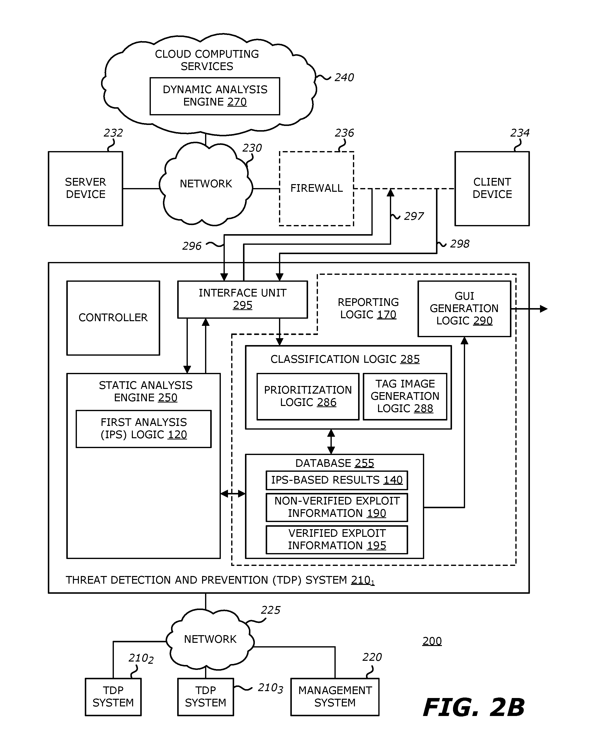
FIG. 2B is a second exemplary block diagram of a communication system deploying a plurality of TDP systems with framework for conducting exploit analysis using IPS logic with results verified by virtual execution logic.
FIG. 3 is an exemplary block diagram of logic associated with the TDP system of FIGS. 2A-2B.
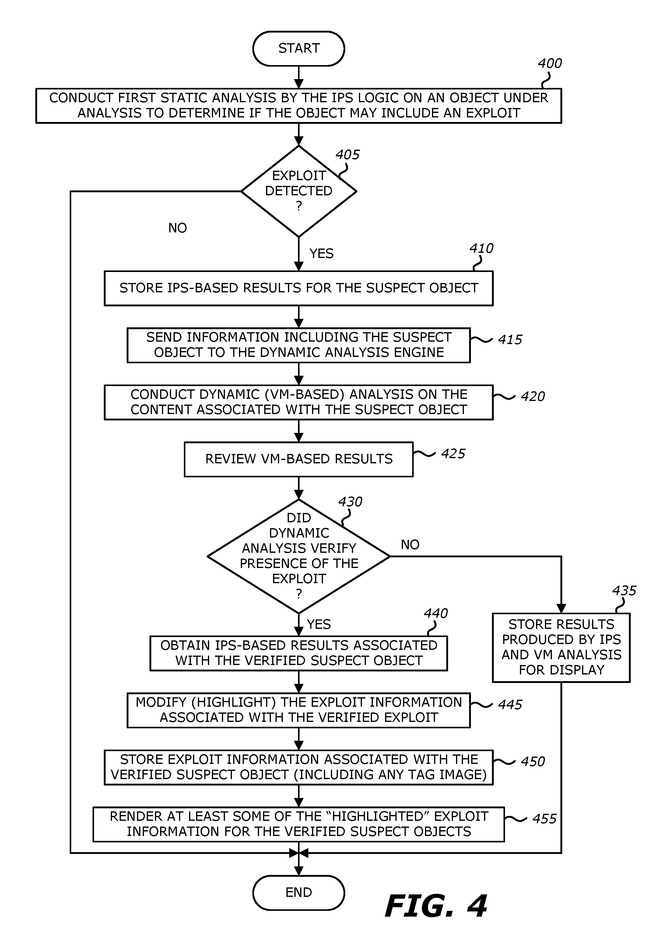
FIG. 4 is an exemplary diagram of a flowchart illustrating operations of the threat detection and prevention process.
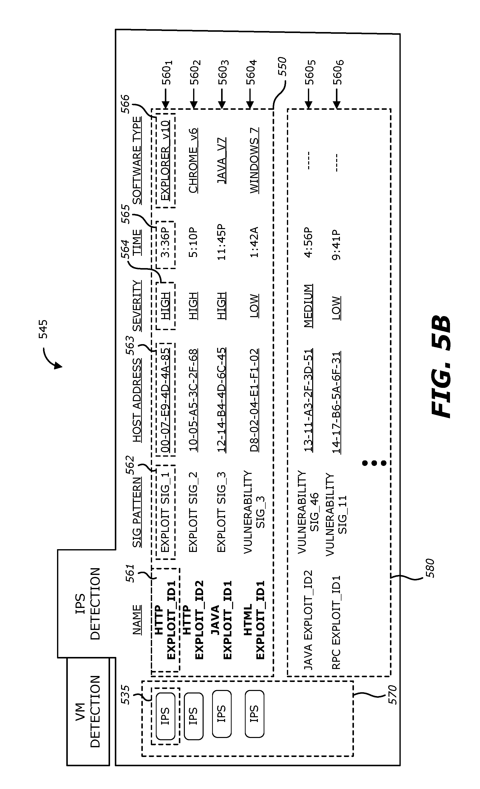
FIGS. 5A-5B are exemplary embodiments of user interface display screens produced by display logic, where the display screens provides an interactive dashboard.
FIGS. 6A-6B are exemplary block diagrams of operational flows of analyzed objects associated with network traffic in accordance with an alternative embodiment of the TCP system.
FIGS. 7A-7B are exemplary block diagrams of a communication system deploying a plurality of threat detection and prevention (TDP) systems with a framework for conducting exploit analysis using intrusion protection system (IPS) logic and heuristic logic with results verified by the virtual execution logic pursuant to the alternative embodiment.
FIGS. 8A-8B are exemplary diagrams of a flowchart illustrating operations of the threat detection and prevention process according to the framework of FIGS. 7A-7B.
DETAILED DESCRIPTION
Various embodiments of the disclosure relate to an electronic device with network connectivity, such as a threat detection and prevention (TDP) system for example, where the electronic device comprises a static analysis engine, a dynamic analysis engine and reporting logic. According to one embodiment of the disclosure, the static analysis engine comprises intrusion protection system (IPS) logic that conducts at least exploit signature checks and/or vulnerability signature checks on objects under analysis to identify whether characteristics of any of these objects are indicative of an exploit. Those objects with these identified characteristics are label "suspect" or "suspicious" objects. The dynamic analysis engine comprises virtual execution logic to automatically and subsequently analyze, without user assistance, content within suspect objects provided from the IPS logic in order to possibly verify whether any of the suspect objects is an exploit.
Based on analysis results from the IPS logic and the virtual execution logic, reporting logic within the TDP system generates a report (e.g., one or more display screens, printed report, etc.) that highlights information associated with these "verified" exploits, namely suspect objects initially identified by the IPS logic that have been verified by the virtual execution logic to be exploits. Some or all of the information associated with the verified exploits (referred to as "verified exploit information") may be highlighted to visibly denote the verified exploits from the non-verified exploits, namely suspect objects initially identified by the IPS logic that have not been verified by the virtual execution logic. Examples as to how the verified exploit information is highlighted may include (1) altering location or ordering of at least certain portions of the verified exploit information to prominently display such information within the report; (2) modifying the font (e.g. color, size, type. style, and/or effects) used in conveying some of the verified exploit information; (3) placement of one or more images proximate to a listing of the verified exploit information; or the like.
I. Terminology
In the following description, certain terminology is used to describe features of the invention. For example, in certain situations, both terms "logic" and "engine" are representative of hardware, firmware and/or software that is configured to perform one or more functions. As hardware, logic (or engine) may include circuitry having data processing or storage functionality. Examples of such circuitry may include, but is not limited or restricted to a microprocessor, one or more processor cores, a programmable gate array, a microcontroller, an application specific integrated circuit, wireless receiver, transmitter and/or transceiver circuitry, semiconductor memory, or combinatorial logic.
Logic (or engine) may be software in the form of one or more software modules, such as executable code in the form of an executable application, an application programming interface (API), a subroutine, a function, a procedure, an applet, a servlet, a routine, source code, object code, a shared library/dynamic load library, or one or more instructions. These software modules may be stored in any type of a suitable non-transitory storage medium, or transitory storage medium (e.g., electrical, optical, acoustical or other form of propagated signals such as carrier waves, infrared signals, or digital signals). Examples of non-transitory storage medium may include, but are not limited or restricted to a programmable circuit; a semiconductor memory; non-persistent storage such as volatile memory (e.g., any type of random access memory "RAM"); persistent storage such as non-volatile memory (e.g., read-only memory "ROM", power-backed RAM, flash memory, phase-change memory, etc.), a solid-state drive, hard disk drive, an optical disc drive, or a portable memory device. As firmware, the executable code is stoned in persistent storage.
The term-object" generally refers to a collection of data, whether in transit (e.g., over a network) or at rest (e.g., stored), often having a logical structure or organization that enables it to be classified for purposes of analysis. During analysis, for example, the object may exhibit a set of expected characteristics and, during processing, a set of expected behaviors. The object may also exhibit a set of unexpected characteristics and a set of unexpected behaviors that may evidence an exploit and potentially allow the object to be classified as an exploit.
Examples of objects may include one or more flows or a self-contained element within a flow itself. A "flow" generally refers to related packets that are received, transmitted, or exchanged within a communication session. For convenience, a packet is broadly referred to as a series of bits or bytes having a prescribed format, which may include packets, frames, or cells.
As an illustrative example, an object may include a set of flows such as (1) a sequence of transmissions in accordance with a particular communication protocol (e.g., User Datagram Protocol (UDP); Transmission Control Protocol (TCP); or Hypertext Transfer Protocol (HTTP); etc.), or (2) inter-process communications (e.g. Remote Procedure Call "RPC" or analogous processes, etc.). Similar, as another illustrative example, the object may be a self-contained element, where different types of such objects may include an executable file, non-executable file (such as a document or a dynamically link library), a Portable Document Format (PDF) file, a JavaScript file, Zip file, a Flash file, a document (for example, a Microsoft Office.RTM. document), an electronic mail (email), downloaded web page, an instant messaging element in accordance with Session Initiation Protocol (SIP) or another messaging protocol, or the like.
An "exploit" may be construed broadly as information (e.g., executable code, data, command(s), etc.) that attempts to take advantage of a software vulnerability. Typically, a "vulnerability" is a coding error or artifact of software (e.g., computer program) that allows an attacker to alter legitimate control flow during processing of the software (computer program) by an electronic device, and thus, causes the electronic device to experience undesirable or unexpected behaviors. The undesired or unexpected behaviors may include a communication-based anomaly or an execution-based anomaly, which, for example, could (1) alter the functionality of an electronic device executing application software in a malicious manner; (2) alter the functionality of the electronic device executing that application software without any malicious intent; and/or (3) provide unwanted functionality which may be generally acceptable in another context. To illustrate, a computer program may be considered as a state machine, where all valid states (and transitions between states) are managed and defined by the program, in which case an exploit may be viewed as seeking to alter one or more of the states (or transitions) from those defined by the program.
Malware may be construed broadly as computer code that executes an exploit to take advantage of a vulnerability, for example, to harm or co-opt operation of an electronic device or misappropriate, modify or delete data. Conventionally, malware is often said to be designed with malicious intent. An object may constitute or contain malware.
The term "transmission medium" is a physical or logical communication path between two or more electronic devices (e.g., any devices with data processing and network connectivity such as, for example. a security appliance, a server, a mainframe, a computer such as a desktop or laptop, netbook, tablet, firewall, smart phone, router, switch, bridge, etc.). For instance, the communication path may include wired and/or wireless segments. Examples of wired and/or wireless segments include electrical wiring, optical fiber, cable, bus trace, or a wireless channel using infrared, radio frequency (RF), or any other wired/wireless signaling mechanism.
In certain instances, the terms "detected" and "verified" are used herein to represent that there is a prescribed level of confidence (or probability) on the presence of an exploit within an object under analysis. For instance, the IPS logic (described below) "detects" a potential exploit by examining characteristics or features of an object under analysis, and, in response, determining whether the object has characteristics indicative of an exploit (a "suspect object"). This determination may be conducted through analysis as to whether there exists at least a first probability of the object under analysis being an exploit. Likewise, the virtual execution logic "verifies" the presence of the exploit by monitoring or observing unexpected or anomalous behaviors or activities, and, in response, determining that suspect object is an exploit. According to one embodiment of the disclosure, the determination by the virtual execution logic may involve an analysis as to whether there exists a second probability of the suspect exploit being an exploit. The second probability may be greater than the first probability and may take into account the first probability.
The term "computerized" generally represents that any corresponding operations are conducted by hardware in combination with software and/or firmware. Also, the terms "compare" or "comparison" generally mean determining if a match (e.g., a certain level of correlation) is achieved between two items where one of the items may include a particular signature pattern.
Lastly, the terms "or" and "and/or" as used herein are to be interpreted as inclusive or meaning any one or any combination. Therefore, "A, B or C" or "A, B and/or C" mean "any of the following: A; B; C; A and 13; A and C; B and C; A, B and C." An exception to this definition will occur only when a combination of elements, functions, steps or acts are in some way inherently mutually exclusive.
The invention may be utilized for detection, verification and/or prioritization of malicious content such as exploits. As this invention is susceptible to embodiments of many different forms, it is intended that the present disclosure is to be considered as an example of the principles of the invention and not intended to limit the invention to the specific embodiments shown and described.
II. First Embodiment--IPS Logic with Virtual Execution Logic Verification
A. Communication Flow
Referring to FIG. 1A, an exemplary block diagram of an operational flow of threat detection and prevention within an electronic device 100 is shown. Herein, some or all of the incoming objects 110 associated with monitored network traffic are received by IPS logic 120, which is part of the static analysis engine of FIGS. 2A-2B for example. The IPS logic 120 is configured as a capture and filter device that receives the incoming objects 110 and filters, using at least exploit signatures and/or vulnerability signatures, which objects are to be provided for more in-depth analysis. The exploit signatures and/or vulnerability signatures may be updated in a periodic or aperiodic manner.
More specifically, a suspected exploit may be detected by conducting exploit signature checks and/or vulnerability signature checks, namely comparing an object under analysis to one or more pre-stored exploit signatures and/or vulnerability signatures to determine if a match is detected. In general, an "exploit signature" includes information directed to a previously detected or known attack pattern while a "vulnerability signature" includes information that characterizes a potential attempt to capitalize on a previously detected or known vulnerability, even when no specific exploit for that vulnerability is known. According to one embodiment of the disclosure, the vulnerability signature may be considered a protocol state machine that maintains state and is normally configured to define parameters for an object being a set of flows that represent an attempt being made to capitalize on a particular software vulnerability that the vulnerability signature is attempting to protect.
Upon conducting at least exploit signature checks and/or vulnerability signature checks on the incoming objects 110 and identifying a first subset of objects 130 having characteristics indicative of an exploit ("suspect objects"), the IPS logic 120 provides the first set of suspect objects 130 to verification logic 150 and provides results 140 of its analysis (referred to herein as "IPS-based results") to reporting logic 170 for storage and subsequent access.
It is contemplated that the first subset of objects 130 may be lesser in number (and potentially significantly less in number) than the incoming objects 110. For example, while the first subset of objects 130 may be a stream of objects. for ease of discussion in this section, the first subset of objects 130 may refer to at least one incoming object initially suspected of being an exploit (e.g., a suspect object matches a pre-stored exploit signature or a vulnerability signature). Hence, the IPS logic 120 routes the suspect object 130 to verification logic 150 and outputs the IPS-based results 140 associated with suspect object 130 to reporting logic 170.
The IPS-based results 140 may provide details directed to one or more suspected exploits within the suspect object 130. As an example, the details may include (i) an exploit identifier such as a particular name/family of the suspected exploit (if known); (ii) source address (e.g., Uniform Resource Locator "URL", Internet Protocol "IP" address, etc.) of the electronic device sending the suspect object; (iii) time of analysis; (iv) information associated with anticipated anomalous activities that may be conducted by the suspected exploit; (v) information regarding anticipated communication deviations from the protocol applicable to the network traffic; and/or (vi) recommended remediation techniques for this type of exploit.
As mentioned above, the suspect object 130 is routed to verification logic 150 (e.g., virtual execution logic being part of a dynamic analysis engine 270 as illustrated in FIGS. 2A-2B). The verification logic 150 attempts to verify whether the suspect object 130 is an exploit by virtual processing content within the suspect object 130 and monitoring behaviors during such virtual processing, as described below.
The results 160 of this analysis are output from the verification logic 150 for subsequent use by reporting logic 170 in generating a report 180 that visibly denotes and filters the suspect objects from the first set of objects 130 that have been verified (verified exploits) from those suspect objects from the first set of objects 130 that have not been verified (non-verified exploits). Although not illustrated in FIG. 1A, the VM-based results 160 may include (1) the suspect object; (2) time of analysis; (3) one or more scores that may be used to verify that the suspect object is likely an exploit, and if so: (i) the exploit identifier; (ii) characteristics or anomalous behaviors associated with the verified exploit, which may include video/images of anomalous behaviors; and/or (iii) name and/or version number of software detected to be vulnerable to the verified exploit.
Thereafter, at least portions of the IPS-based results 140 and the VM-based results 160 for the suspect object are combined. More specifically, in the event that the VM-based results 160 indicate that the verification logic 150 failed to verify that the suspect object 130 is an exploit (e.g., a computed score below a prescribed threshold), some or all of the IPS-based results 140 and the VM-based results 160 for that object are combined and added as part of "non-verified exploit information" 190 for storage and use by the reporting logic 170.
However, when the VM-based results 160 indicate that the verification logic 150 has verified that the suspect object 130 is an exploit (e.g., the computed score is equal to or above a prescribed threshold), some or all of the IPS-based results 140 and the VM-based results 160 may be modified to achieve a highlighted display of at least the verified exploits. For example, certain portions of the results 140 and/or 160 may be associated with display commands, which are recognized by a display controller being part of display logic within the reporting logic 170 and causes the display logic to produce an output that may visibly denotes differences between displayed results associated with verified exploits from displayed results associated with the non-verified exploits. This exploit information associated with the verified exploit may be stoned as part of the "verified exploit information" 195.
The display logic 290 also may be configured to recognize that the verified exploit information 195 is to be displayed more prominently than the non-verified exploit information 190. For instance, display logic 290 may be configured to prominently display the verified exploit information within different display screens, within different display windows, within a certain section of a display screen, or positioned at a top of a listing. Additionally or in the alternative, at least a portion of the verified exploit information for each verified exploit may be conveyed using a different font (e.g., color, size, type, style, and/or effects) than the font used for conveying exploit information associated with non-verified exploits. Additionally or in the alternative, one or more images may be placed proximate to exploit information associated with each verified exploit. illustrative examples of screen displays are shown in FIGS. 5A-5B.
Besides displaying the exploit information, the reporting logic 170 may issue an alert (e.g., by email or text message) to security administrators for example, communicating the urgency in handling one or more verified exploits. The reporting logic 170 may also issue alerts for one or more non-verified exploits by providing alerts in a manner that denotes to users a selected threat level.
As further shown, the IPS logic 120 may be communicatively coupled to a network 105 (e.g., public or private network) to receive incoming objects 110, such as one or more flows for example, destined for a particular client device. The IPS logic 120 is configured to conduct exploit signature checks and/or vulnerability signature checks on the incoming objects 110 to determine whether any of the objects 110 have characteristics indicative of an exploit, and thereafter, provide the suspect object(s) 130 to verification logic 150.
According to one embodiment of the disclosure, the communicative coupling between the IPS logic 120 and the verification logic 150 is provided in a sideband configuration, where the suspect object(s) 130 (or a copy thereof) may be temporarily stored and processed in the verification logic 150 concurrently with analysis of other objects by the IPS logic 120. This allows for the detection of exploits through a longer duration of analysis by the verification logic 150 (e.g., longer processing and monitoring of processing of the suspect object 130 within the virtual execution logic). This also allows detection of exploits with delayed activation, including time-bombs. However, it is contemplated that the IPS logic 120 may be configured in-line with verification logic 150 as shown in FIG. 1B. Herein, the IPS logic 120 may provide both the suspect objects 130 and IPS-based results 140 to the verification logic 150, where the IPS-based results may be subsequently routed to reporting logic 170 from the verification logic 150.
B. General Architecture--First Embodiment
Referring to FIG. 2A, an exemplary block diagram of a communication system 200 deploying a plurality of threat detection and prevention (TDP) systems 210.sub.1-210.sub.N (N>1, e.g., N=3) communicatively coupled to a management system 220 via a network 225 is shown. In general, management system 220 is adapted to manage TDP systems 210.sub.1-210.sub.3. For instance, management system 220 is responsible for automatically updating one or more exploit signatures and/or vulnerability signatures used by IPS logic within some or all of TDP systems 210.sub.1-210.sub.N. Each of these signatures may represent a prior detected exploit or an uncovered software vulnerability. Such sharing may be conducted automatically or manually uploaded by an administrator. Also, such sharing may be conducted freely among the TDP systems 210.sub.1-210.sub.3 or subject to a subscription basis.
Herein, according to the embodiment illustrated in FIG. 2A, a first TDP system 210.sub.1 is an electronic device that is adapted to analyze information associated with network traffic routed over a communication network 230 between at least one server device 232 and at least one client device 234. The communication network 230 may include a public network such as the Internet, in which case an optional firewall 236 (represented by dashed lines) may be interposed prior to accessing client device 234. Alternatively, the communication network 230 may be a private network such as a wireless data telecommunication network, wide area network, a type of local area network (LAN), or a combination of networks.
As shown, the first TDP system 210.sub.1 may be communicatively coupled with the communication network 230 via a network interface 238. In general, the network interface 238 operates as a data capturing device (sometimes referred to as a "tap" or "network tap") that is configured to receive data propagating to/from the client device 234 and provide at least some of this data to the first TDP system 210.sub.1. Alternatively, as shown in FIG. 2B, the first TDP system 210.sub.1 may be positioned behind the firewall 236 and in-line with client device 234.
According to one embodiment of the disclosure, the network interface 238 is capable of receiving and routing objects associated with network traffic to the first TDP system 210.sub.1. The network interface 238 may provide the entire object or certain content within the object, for example, one or more files that are part of a set of flows, packet payloads, or the like. In some embodiments, although not shown, network interface 238 may be contained within the first TDP system 210.sub.1.
According to an embodiment of the disclosure, the network interface 238 may be further configured to capture metadata from network traffic intended for client device 234. According to one embodiment, the metadata may be used, at least in part, to determine protocols, application types and other information that may be used by logic within the first TDP system 210.sub.1 to determine particular software profile(s). The software profile(s) are used for selecting and/or configuring a run-time environment in one or more virtual machines selected or configured as part of the dynamic analysis engine 270, as described below. However, according to another embodiment, a "matched" vulnerability signature may be used for VM configuration to specify software profile(s) (or corresponding software image(s)) having the specific vulnerability associated with the matched vulnerability signature. These software profile(s) may be directed to different versions of the same software application for fetching corresponding software image(s) from storage device 265.
It is contemplated that, for any embodiments where the first TDP system 210.sub.1 is implemented as an dedicated appliance or a dedicated computer system, the network interface 238 may include an assembly integrated into the appliance or computer system that includes a network interface card and related logic (not shown) for connecting to the communication network 230 to non-disruptively "tap" network traffic propagating through firewall 236 and provide either a duplicate copy of at least a portion of the network traffic or at least a portion the network traffic itself to a static analysis engine 250. In other embodiments, the network interface 238 can be integrated into an intermediary device in the communication path (e.g., firewall 236, router, switch or other networked electronic device, which in some embodiments may be equipped with SPAN ports) or can be a standalone component, such as an appropriate commercially available network tap. In virtual environments, a virtual tap (vTAP) can be used to duplicate files from virtual networks.
As further shown in FIG. 2A, the first TDP system 210.sub.1 comprises the static analysis engine 250, a database 255, a scheduler 260, a storage device 265, a dynamic analysis engine 270, an optional classification logic 285, and a display logic 290. It is contemplated that the functionality of the classification logic 285 may be integrated into the display logic 290, where the display logic 290 would be configured with the prioritization logic 286 and/or the tag image generation logic 288.
In some embodiments, as shown in FIGS. 2A-2B, static analysis engine 250 may include one or more software modules that, when executed by one or more processors, performs multi-level static scanning on a particular object, namely exploit signature checks and/or vulnerability signature checks by IPS logic 120. Such signature check operations may involve accessing pre-stored signatures from one or more non-transitory storage mediums such as signature database 251. The static analysis engine 250 and the dynamic analysis engine 270 may be one or more software modules executed by the same processor or different processors, where these different processors may be located within the same processor package (e.g., different processor cores) and/or located at remote or even geographically remote locations that are communicatively coupled (e.g. by a dedicated communication link) or a network.
In general, referring to FIG. 2A, the static analysis engine 250 is communicatively coupled to receive one or more objects from network traffic which may be related or unrelated to each other. For instance, one object may be a series of HTTP packets operating as a flow routed over communication network 230. The static analysis engine 250 comprises IPS logic 120, where the IPS logic 120 analyzes each of the objects for known exploits using exploit signatures as well as for the protocol activity using vulnerability signatures. For instance, the exploit matching logic 252 within the IPS logic 120 performs exploit signature checks, which may involve a comparison of one or more pre-stored exploit signatures (pre-configured and predetermined attack patterns against the suspect object) from signature database 251. Similarly, the signature matching logic 253 within the IPS logic 120 performs vulnerability signature checks, which may involve a process of uncovering deviations in messaging practices set forth in applicable communication protocols (e.g., HTTP, TCP, etc.). As an illustrative example, HTTP messages may be analyzed to determine compliance with certain message formats established for the protocol (e.g., out-of-order commands). Furthermore, payload parameters of the HTTP messages may be analyzed to determine further compliance.
Upon detecting a match during the exploit signature check and/or the vulnerability signature check (an object under analysis has characteristics that suggest the object is an exploit), the IPS logic may be adapted to upload the IPS-based results 140 for storage in database 255. These results 140 may include, but are not limited or restricted to (i) an exploit identifier such as a particular name/family of the suspected exploit (if known); (ii) source address (e.g., Uniform Resource Locator "URL", Internet Protocol "IP" address. etc.) of a source of the suspect object; (iii) time of analysis; (iv) information associated with anticipated anomalous activities that may be conducted by the suspect exploit; (v) information regarding anticipated communication deviations from the protocol applicable to the network traffic; and/or (vi) recommended remediation techniques. The IPS-based results 140 may be accessible by classification logic 285 and/or display logic 290, as described below.
Furthermore, the IPS logic 120 routes suspect object to the virtual execution logic 150 within dynamic analysis engine 270. The dynamic analysis engine 270 is configured to provide more in-depth analysis of suspect object(s) from the IPS logic 120 by analyzing the content of the suspect object(s) in order to verify whether or not the suspect object is an exploit. Additionally, according to one embodiment of the disclosure, a tag value may accompany or be associated with the suspect object for use in subsequently locating the suspect object's corresponding stored IPS-based results 140 after virtual processing within the dynamic analysis engine 270. For instance, the tag value may be an address, an index number, or the like. It is contemplated that tag value may be separate from the suspect object or may be strategically placed within the suspect object itself (e.g., within a header portion, payload, etc.).
More specifically, after static scanning has been completed, the IPS logic 120 provides the suspect object to the dynamic analysis engine 270 for in-depth dynamic analysis using virtual machines (VMs) 275.sub.1-275.sub.M (M>1). For instance. the dynamic analysis engine 270 may simulate transmission and/or receipt by a destination device comprising the virtual machine. Of course, if the object is not suspected of being an exploit, the IPS logic 120 may simply store the IPS-based results within database 255 and denote that the object is benign.
According to one embodiment, one or more VMs 275.sub.1-275.sub.m within the virtual execution environment 272 may be configured based on the results of the exploit signature check and the vulnerability signature check conducted by the IPS logic 120. For instance, for an unknown vulnerability, the VMs 275.sub.1-275.sub.M may be configured with all of the software profiles corresponding to the software images stored within storage device 265. Alternatively, the VMs 275.sub.1-275.sub.M may be configured according to a prevalent software configuration, software configuration used by an electronic device within a particular enterprise network (e.g., client device 234), or an environment that is required for the object to be processed, including software such as a web browser application, PDF1'm reader application, or the like. However, for a known vulnerability which occurs after a successful match during a vulnerability signature check, the VMs 275.sub.1-275.sub.M may be more narrowly configured to software profiles associated with vulnerable software.
As a first illustrative example, upon determining that the suspect object matches a particular vulnerability signature. the scheduler 260 may determine (1) what vulnerability signature has been tagged; (2) if the vulnerability is a server side vulnerability or client side vulnerability; and/or (3) which software image(s) are associated with software having the vulnerability associated with the tagged vulnerability signature. Thereafter, the software profile(s) are selected by the scheduler 260 to fetch these software image(s) for configuration of VM 275.sub.1. This tailored selection scheme avoids VM configuration for software that does not feature the matched (tagged) software vulnerability.
As a second illustrative example, the scheduler 260 may be adapted to configure the multiple VMs 275.sub.1-275.sub.M for concurrent virtual execution of a variety of different versions of the software in efforts to verify that the suspect object identified by the signature matching logic 253 is an exploit.
Of course, it is contemplated that the VM configuration described above may be handled by logic other than the scheduler 260. For instance, although not shown, the static analysis engine 250 may include configuration logic that is adapted to determine (1) what vulnerability signature was tagged; (2) if the vulnerability is a server side vulnerability or client side vulnerability; and/or (3) which software image(s) are associated with software having the vulnerability associated with the tagged vulnerability signature. This configuration logic may transmit the VM configuration information to the scheduler 260 and/or dynamic analysis engine 270 to handle VM configuration as described above.
According to one embodiment of the disclosure, the dynamic analysis engine 270 is adapted to execute one or more VMs 275.sub.1-275.sub.M to simulate the receipt and execution of content associated with an object under analysis within a run-time environment as expected by the type of object. For instance, dynamic analysis engine 270 may optionally include a protocol sequence replayer (replay logic) 280 to replay the suspect object and provide replayed data flows to the VM(s) 275.sub.1, . . . , and/or 275.sub.M or object extractor logic 282 to extract a self-contained object within a data flow for virtual processing by VM(s) 275.sub.1, . . . and/or 275.sub.M. One embodiment of the protocol sequence replayer is described in U.S. Pat. No. 8,375,444, the entire contents of which are incorporated by reference herein.
For example, the replay logic 280 may be adapted to provide, and sometimes modify (e.g. modify IP address, etc.) packets associated with the suspect objects and synchronize any return network traffic generated by the virtual execution environment 272 in response to the packets. Hence, the replay logic 280 may suppress (e.g., discard) the return network traffic such that the return network traffic is not transmitted to the communication network 230. According to one embodiment of the disclosure, for a particular suspect object being a flow such as a TCP or UDP sequence, the replay logic 280 may replay the data packets by sending packets to the virtual execution environment 272 via a TCP connection or UDP session. Furthermore, the protocol sequence replay logic 280 synchronizes return network traffic by terminating the TCP connection or UDP session.
As further shown in FIG. 2A, the monitoring logic 276 within the dynamic analysis engine 270 may be configured to monitor behavior of the content being analyzed by one or more VMs 275.sub.1, . . . , and/or 275.sub.M, for detecting anomalous or unexpected activity indicative of an exploit. If so, the content may be determined as being associated with malicious activity, and thereafter, monitoring logic 276 operating with a score determination logic 278 may route the VM-based results 160 (e.g., computed score, information associated with the detected anomalous behaviors, and other information associated with the detected malicious activity by the suspect object) to classification logic 285 and/or database 255. It is noted that the tag value, if used, may be provided as part of the VM-based results 160.
According to one embodiment of the disclosure, the score determination logic 278 comprises one or more software modules that are used to determine a probability (or level of confidence) that the suspect object is an exploit. Score determination logic 278 is configured to generate a value (referred to as a "score") that classifies the threat of the possible exploit. Of course, a score may be assigned to the suspect object as a whole by mathematically combining the scores determined by analysis of different content associated with the same suspect object to obtain an overall score for that suspect object. Thereafter, the suspect object and/or score are routed to classification logic 285 for use in prioritization.
In general, the classification logic 285 may be configured to receive the VM-based results 160. According to one embodiment of the disclosure, the score may be used, at least in part, to determine whether the virtual execution logic 150 has verified that the suspect object is an exploit. Where the score represents that the suspect object 130 has not been verified by the virtual execution logic 150 to have the characteristics of an exploit, some or all of the VM-based results 160 may be combined with its corresponding IPS-based results to produce the non-verified exploit information 190, which is stored in database 255.
However, if the score represents that the suspect object 130 has been verified by the virtual execution logic 150 as an exploit, at least some of the combined IPS-based results 140 and/or the VM-based results 160 may be modified by the classification logic 285 and subsequently stored as at least part of the verified exploit information 195. Stated differently, the classification logic 285 operating with the database 255 may be responsible for prioritizing the display of exploit information associated with the verified exploits. This may involve the classification logic 285 modifying order or position for the displayed verified exploit information, or adding information to the verified exploit information that is used by the display logic 290 to modify display order or positioning; modifying the type of font (e.g., color, size. type, style, and/or effects) used for text conveying certain verified exploit information: placing one or more images proximate to verified exploit information for each verified exploit; or the like.
Of course, it is contemplated that other parameters, combined with or separate from the score, may be used or relied upon to determine whether and/or how to highlight display of the exploit information associated with the suspect object.
Thereafter, along with non-verified exploit information 190, the verified exploit information 195 is stored within database 255 and accessible by display logic 290.
More specifically, according, to one embodiment of the disclosure, classification logic 285 comprises prioritization logic 286 and tag image generation logic 288. According to one embodiment of the disclosure, the prioritization logic 286 may be adapted to modify (e.g., alter or associate display commands to) exploit information associated with verified exploits based one or more factors, including (i) score associated with the object; (ii) source of the object; (iii) repeated detection of the same exploit in different suspect objects; or the like. This modification may involve modifying font (e.g., color, size, type, style, and/or effects) used to convey the exploit information associated with verified exploits. As another example, this modification may involve classification and storage of the exploit information as verified exploit information 195 which, when accessed by the display logic 290, places the exploit information associated with the verified exploit at a specific location on a display screen or within display image (e.g., within a specific window or display screen listing the verified exploits, at a particular order within the listing of the verified and non-verified exploits, etc.).
Of course, as an alternative, the display logic 290 may be implemented with some or all of the functionality associated with the prioritization logic 286 and/or tag image generation logic 288 in lieu of deployment within the classification logic 285. Hence, responsive to information received from the classification logic, the display logic 290 may be adapted to modify exploit information associated with verified exploits.
The tag image generation logic 288 may be adapted to operate in combination with the prioritization logic 286 to generate a tag image (not shown), which is included as part of the verified exploit information 195 associated with suspect object for display. The tag image is used to provide another visual representation of the presence of a verified exploit, namely a suspected exploit detected by the IPS logic 120 whose presence has been verified by the virtual execution logic 150.
Of course, in lieu of or in addition to static scanning operations being conducted by TDP systems 210.sub.1-210.sub.3, it is contemplated that cloud computing services 240 may be implemented with IPS logic 120 to perform the exploit and/or vulnerability signature checks and/or with virtual execution logic 150 to conduct virtual execution on content within the object under analysis, as described herein. The display logic 290 may cause the display of the exploit information associated with the verified exploits and/or non-verified exploits graphically or otherwise through a downloaded page or pages from the cloud computing services 240 to a client device or to an application running on a client device that displays the results obtained from the cloud computing services 240. In accordance with this embodiment, TDP system 210.sub.1 may be adapted to establish secured communications with cloud computing services 240 for exchanging information.
C. General Architecture--Second Embodiment
Referring now to FIG. 2B, first TDP system 210.sub.1 may be coupled with the communication network 230 in line with client device 234. Contrary to the embodiment illustrated in FIG. 2A, first TDP system 210.sub.1 comprises an interface unit 295 that directs signaling on communication network 230 to static analysis engine 250 or classification logic 285, given that the dynamic analysis engine 270 is deployed in cloud computing services 240. Hence, objects from network traffic for static analysis are routed to static analysis engine 250 via communication path 296. The suspicious objects may be routed via path 297 to the dynamic analysis engine 270 in cloud computing services 240. Similarly, objects that are not determined to be at least "suspect" may be returned via path 297 for continued routing to client device 234. The results of the dynamic analysis engine 270 (e.g., exploit information) may be routed via path 298 for prioritization and tagging before storage within database 255 for subsequent use by display logic 290.
D. Exemplary Logic Layout of TDP System
Referring now to FIG. 3, an exemplary block diagram of logic associated with TDP system 210.sub.1 of FIGS. 2A-2B is shown. TDP system 210.sub.1 comprises one or more processors 300 that are coupled to communication interface logic 310 via a first transmission medium 320. Communication interface logic 310 enables communications with other TDP systems 210.sub.1-210.sub.3 and management system 220 of FIG. 2A-2B. According to one embodiment of the disclosure, communication interface logic 310 may be implemented as a physical interface including one or more ports for wired connectors.
Additionally, or in the alternative, communication interface logic 310 may be implemented with one or more radio units for supporting wireless communications with other electronic devices.
Processor(s) 300 is further coupled to persistent storage 330 via transmission medium 325. According to one embodiment of the disclosure, persistent storage 330 may include (i) static analysis engine 250. including first analysis logic (e.g., IPS logic) 250; (ii) the dynamic analysis engine 270. including virtual execution logic 272, monitoring logic 276, score determination logic 278 along with optional replay and object extractor logic 280 and 282; (iii) classification logic 285 including prioritization logic 286 and tag image generation logic 288; and (iv) display logic 290. Of course, when implemented as hardware, one or more of these logic units could be implemented separately from each other.
IPS logic 120 comprises one or more software modules that conduct a first static analysis on each incoming object. As described above, this analysis may involve performing at least exploit signature checks and vulnerability signature checks on each incoming object to determine whether characteristics of any of these objects are indicative of an exploit. If not, the analysis may be discontinued for the object, or the object may be provided for non-real time forensic review. Upon confirming that one or more suspect objects have characteristics of an exploit, the IPS logic 120 provides the suspect object(s) to the virtual execution logic 150. It is contemplated that a tag value, if used, may accompany (or be associated with) the suspect object to identify a stored location of the IPS-based results 140 for the suspect object, as described above. The IPS-based results 140 are uploaded to data store 350, at least partially operating as a database, for subsequent access by classification logic 285.
Virtual execution environment 272 comprises one or more software modules that are used for performing an in-depth, dynamic and real-time analysis of the suspect object using one or more VMs. More specifically, the virtual execution environment 272, protocol sequence replay logic 280 and/or object extractor logic 282 are adapted to run the VM(s), which virtually processes the content associated with the suspect objects by simulating receipt and execution of such content in order to determine the presence of one or more exploits. Furthermore, the monitoring logic 276 monitors in real-time and may also log at least anomalous behaviors by the VM(s) configured with certain software and features that are presumably targeted by the matched exploit or vulnerability. In essence, the monitoring logic 276 identifies the effects that the suspect object would have had on a physical electronic device with the same software/feature configuration. Such effects may include unusual network transmissions, unusual changes in performance, and the like.
Thereafter, according to the observed behavior of the virtually executed content, the monitoring logic 276 may determine that the content is associated with one or more exploits, where the severity of the observed anomalous behavior and/or the likelihood of the anomalous behavior results from an exploit, is evaluated and reflected in a "score" assigned by the score determination logic 278. As a result, these logic units collectively output the VM-based results 160 for use by classification logic 285 to highlight exploit information associated with verified exploits.
The prioritization logic 286 comprises one or more software modules that are used to highlight information associated with verified exploits, namely the verified exploit information 195. For instance, the prioritization logic 286 may assign higher priority to exploit information directed to verified exploits, where the priority may be used by the display logic 290 to determine an order or location for display. Furthermore, the prioritization logic 286 may be adapted to modify the font used in display of the verified exploit information (e.g., color, size, type, style, and/or effects), or control the placement of one or more images provided by the tag image generation logic 288 proximate to its corresponding exploit information.
Continuing the above example, processor(s) 300 may invoke display logic 290, which produces one or more screen displays for conveying a detailed summary of verified and/or non-verified exploits detected by the TDP system 210.sub.1. According to one embodiment of the disclosure, the information associated with the verified exploits (verified exploit information 195) may be presented in a first area of a display screen while information associated with the non-verified exploits (non-verified exploit information 190) may be presented in a second area of the display screen. As another example, the verified exploit information 195 may be presented as top entries in a listing of all exploits detected by the IPS logic while the non-verified exploit information 190 is presented subsequently. As another example, some or all of the verified exploit information 195 may be presented in different font (e.g., different type, color, style such as bold or italic, effects such as underlining or shadow, etc.) than font used for conveying the non-verified exploit information 190. As yet another example, a tag image may be positioned next to the verified exploit information 195 unlike non-verified exploit information 190 associated with suspect objects.
E. Display and Prioritization of Detected Exploits
Referring to FIG. 4, an exemplary diagram of a flowchart illustrating a threat detection and prevention process which generates a report that highlights information associated with suspected exploits detected by the IPS logic and verified by the virtual execution environment is shown. Upon receipt of an object. the TDP system conducts a first static analysis operation on the object (block 400). Herein, the first static analysis operation may include exploit signature checks and/or vulnerability signature checks by the IPS logic to determine whether characteristics of an object under analysis are indicative of an exploit. Upon determining that the suspect object may have the characteristics of one or more suspected exploits, the object is tagged for VM-based analysis and information associated with the suspect object and/or potential exploit (IPS-based results) is stored for subsequent access (blocks 405 and 410).
Although not shown, when determining that the suspect object has characteristics of a suspected exploit, the IPS logic may be configured to block the object from proceeding to the targeted client device, although blocking may be delayed until completion of the VM-based analysis to mitigates errors due to false positives. This blocking functionality may be adjusted by the network administrator based on the severity/type of suspected exploit, number of occurrences of this type of exploit within a prescribed time period, or the like. Furthermore, prior to performing further exploit analysis, if used, a tag value may accompany (or being associated with) the suspect object when output from the IPS logic so that the IPS-based results for the suspect object can be related to the subsequent VM-based results for that object.
After IPS-based analysis for the suspect object has concluded, the content of the suspect object may undergo VM-based analysis (blocks 415 and 420). The results of the VM-based analysis (VM-based results) are provided for subsequent review (block 425). According to one embodiment of the disclosure, the classification logic performs such review, although in the alternative, logic within the dynamic analysis engine may conduct this review.
Normally, if the VM-based analysis fails to verify that the suspect object is an exploit, a score may be assigned to denote that no exploit has been detected (block 430). In this case, information produced during the VM analysis of the suspect object along with its corresponding IPS-based results are stored as part of the non-verified exploit information (block 435). However, during virtual execution of the object, if the monitored behavior denotes that the suspect object is an exploit, a score is assigned that represents the likelihood and/or threat level for the "verified" exploit(s).
According to one embodiment of the disclosure, the classification logic may be configured to obtain the IPS-based results associated with the verified exploit, where some or all of the information from the IPS-based results and the VM-based results may be prominently displayed (highlighted) as illustrated in blocks 440 and 445. Such highlighting may include (i) assigning a specific display location for exploit information associated with verified exploits that is different from exploit information associated with non-verified exploits; (ii) modifying the presentation (e.g., font type, color, style, etc.) of exploit information associated with verified exploits where the exploit information associated with the non-verified exploits will have a different presentation; (iii) controlling placement of one or more images proximate to exploit information associated with verified suspect objects only. Other display adjustments may be used, as this highlighting is conducted to visibly differentiate exploit information associated with the verified exploits from exploit information associated with the non-verified exploits.
Thereafter, the (highlighted) verified exploit information is uploaded into the database for storage and now accessible by display logic for rendering (blocks 450 and 455).
F. Display Screens of Detected Malicious Objects
Referring now to FIG. 5A, an exemplary embodiment of a first user interface display screen 500 produced by the display logic of FIGS. 2A-28 that provides an interactive dashboard is shown. Herein, rendered by the display logic, the display screen 500 comprises a plurality of display areas 510 and 530 that illustrate information directed to exploits uncovered over a selected time period by the TDP system. It is noted that multiple highlighting techniques are shown in display screens 500 and 545, although it is contemplated that any one or more highlighting technique may be conducted for a particular display.
More specifically, according to one embodiment of the disclosure, a first area 510 displays a plurality of entries 520.sub.1-520.sub.R (R>1, R=6 for this embodiment) that provide information directed verified exploits and/or non-verified exploits. As shown, each row of entries (e.g., 520.sub.1) rendered by the display logic comprises a plurality of fields, including one or more of the following: (1) a name 521 of the exploit associated with a suspect object; (2) a signature pattern 522 applicable to the object under analysis; (3) addressing information 523 (e.g., Internet Protocol "IP" address, Media Access Control "MAC" address, etc.) for a source device providing the verified or non-verified exploit; (4) a level of severity 524 (e.g., high, medium, low) of the detected exploit, where the severity level corresponds, at least in part, to the threat score; (5) a time 525 during which the exploit analysis process was conducted; and/or (6) name and/or version number 526 of software detected to be vulnerable to the detected exploit.
A second area 530 may be configured with one or more images corresponding to each entry for a verified exploit, namely an object initially identified by the IPS logic as having characteristics indicative of an exploit and verified of being an exploit by the virtual execution logic. For instance, as illustrated in FIG. 5A, image 535 is displayed proximate to information associated with a corresponding verified exploit named "HTTP Exploit_ID1." Similar images are illustrated for verified exploit information associated with verified exploits named "HTTP Exploit_ID2," "Java Exploit_ID1," and "HTML Exploit_ID1."
It is noted that the mere existence of a verified exploit may warrant heightened severity level, but does not require heightened severity levels as illustrated by the fact that certain non-verified exploits may be assigned higher severity levels than some verified exploits. Rather. exploit information associated with the verified exploits is highlighted, namely this exploit information is displayed more prominently than exploit information associated with non-verified exploits for example. This allows a network administrator to more quickly and easily determine verified exploits and thereby substantially mitigate administrative and operational disadvantages from false-positives.
As an example, as a highlighting technique, the font associated with the exploit names (HTTP Exploit_ID1; HTTP Exploit_ID2; Java Exploit_ID1; and HTML Exploit_ID1) may be displayed differently than the font associated with the exploit names for non-verified exploits (e.g., Java Exploit_ID2). Alternatively, the verified exploit information associated with the verified exploits may be ordered at the top of the listing (see FIG. 5B). Also, a single display screen may produce two areas, where a first area includes exploit information associated with verified exploits while a second area includes exploit information associated with non-verified exploits (see FIG. 5B).
Furthermore, although not shown, it is contemplated that selection of a portion of the entry (e.g., entries within fields 521/522/523/524/526 (as represented by an underlined portion) and/or a separate "Details" field 540) may enable the network administrator to obtain more detailed information of the exploit and/or analysis associated with that exploit.
For instance, by selecting the particular listed exploit 521, the administrator may be able to uncover family and other information related to the exploit (e.g., documented attacks, recommended remediation techniques, targeted client device(s), etc.). Also, by selecting the signature 522, the administrator may have access to additional information concerning what signature (exploit, vulnerability, etc.) was determined by the IPS to match the suspect object. Additional information (e.g., information on signature updates, detection history of this signature with other objects, etc.) may be provided as well.
Similarly, by selecting the corresponding host address 523 or the severity level 524, the administrator may be provided with additional information directed to geographic location of the source of the suspect object corresponding to that exploit, addressing information directed to intermediary devices that received the suspect object, the particular network operations targeted by the exploit, or the like. Also, by selecting the software type 526, a listing of all software types detected to be vulnerable to the verified exploit (along with video/images of monitored anomalous behaviors denoting the presence of such exploit) may be accessed.
Referring now to FIG. 5B, an exemplary embodiment of a second user interface display screen 545 produced by the display logic of FIGS. 2A-2B that provides an interactive dashboard is shown. Herein, the display screen 545 comprises a plurality of areas 550, 570 and 580 that display results of IPS detection analysis over a selected time period.
As shown, similar to the first user interface display screen 500, first area 550 of the second user interface display screen 545 displays a plurality of entries 5601-560s (S>1, S=4 for this embodiment) that provides information directed to verified exploits. Each of the entries (e.g., 5601) rendered by the display logic comprises: (1) a name 561 of the verified exploit (suspect object verified to be an exploit); (2) a signature 562 that initially identified the suspect object as having characteristics indicative of an exploit; (3) addressing information 563 (e.g., Internet Protocol "IP" address, Media Access Control "MAC" address, etc.) for a source device providing the detected exploit; (4) a level of severity 564 (e.g., high, medium, low) of the detected exploit that corresponds, at least in part, to the threat score; (5) a time 565 during which the exploit analysis process was conducted; and/or (6) name and/or version number 566 of software detected to be vulnerable to the detected exploit.
As shown, a second area 570 may be provided, which comprises an image corresponding to each entry that is associated with the verified exploits, as described above. As illustrated in FIG. 5B, image 535 is displayed with information associated with a corresponding verified exploit named "HTTP Exploit_ID1." Similar images are illustrated as highlighted verified exploit information for verified exploits named "HTTP Exploit_ID2," "Java Exploit_ID1," and "HTML Exploit_ID1."
A third area 580 illustrates exploit information associated with non-verified exploits named "Java Exploit_1D2", "RPC Exploit_ID1" for example.
III. Alternative Embodiment--IPS Logic & Secondary Analysis Logic with Virtual Execution Logic Verification
According to an alternative embodiment of the disclosure, the static analysis engine may be configured with a first static analysis logic (e.g., IPS logic) and a second static analysis logic (e.g., heuristic logic), which is configured to operate independently from the IPS logic and identifies whether characteristics of any of the incoming objects are indicative of an exploit. As described below, the first static analysis logic and the second static analysis logic may operate in parallel or in tandem.
In particular, as described above, the first static analysis logic (IPS logic) conducts at least exploit signature checks and/or vulnerability signature checks on the incoming objects to identify a first subset of objects having characteristics indicative of an exploit. The second static analysis logic (heuristic logic) may be configured to analyze the same or different objects, where such analysis may be in accordance with at least a set of rules and/or signatures different than those utilized by the first static analysis logic (IPS logic).
More specifically, according to this embodiment of the invention, upon identifying the suspect objects (fast subset of objects), the first static analysis logic (IPS logic) provides suspect objects, perhaps each accompanied by or associated with a tag identifier (hereinafter referred to as "tag_1D1"), to the verification logic 150 of FIGS. 6A-6B. Tag_ID1 may be used to indicate to other logic that the suspect object originated from the first static analysis logic (IPS logic).
The second static analysis logic (heuristic logic) is configured to analyze the incoming objects to determine whether the presence, absence or modification of information within an object may denote potential malicious activity indicating that object may be an exploit. Such determination may involve the second static analysis logic (heuristic logic) conducting operations to determine whether certain portions of the object corresponds to one or more "malicious identifiers," which may include, but are not limited or restricted to a particular source or destination address (e.g., URLs, IP addresses, MAC addresses, etc.) that is associated with known exploits; exploit patterns; or shell code patterns.
Additionally, with each suspect object, the heuristic logic may provide a tag identifier (tag_ID2) for use in locating corresponding heuristic-based results 640 associated with each suspect object 630. Hence, to LD2 may be further used to identify to other logic that this suspect object originated from the heuristic logic 620.
After either the first static analysis logic (IPS logic) or the second static analysis logic determine which of the incoming objects have characteristics indicative of an exploit, the suspect objects are provided to the virtual execution logic for more in-depth dynamic analysis using one or more virtual machines (VMs). Such dynamic analysis may include virtual execution of the content of the suspect objects with one or more configured VMs, as described above. The behaviors of the VM(s) are monitored for detection of anomalous or unexpected activity.
It is contemplated that the first static analysis logic (IPS logic) and the second static analysis logic (heuristic logic) may operate in parallel in which both of these logic units conduct the preliminary exploit detection analysis on the same suspect objects. More specifically, the second static analysis logic (heuristic logic) may conduct its analysis on an object extracted from the network traffic concurrently (i.e., at least partially overlapping in time) with the analysis of the same object by the IPS logic. This provides the TDP system with an ability to account for false negatives that signify a lack of detection of an exploit by the IPS logic. Also, such parallel analysis may be conducted in order to increase scrutiny of network traffic for objects originating from a certain geographic location prone to exploits, from a certain IP addresses that have been identified as a malicious source, or the like.
Of course, it is contemplated that the first static analysis logic (IPS logic) and second static analysis logic (heuristic logic) may operate in tandem in which an incoming object is capable of being processed by either the IPS logic or the heuristic logic within the embodiment. Control of the selection as to whether the static analysis is performed by the first static analysis logic (IPS logic) or the second static analysis logic (heuristic logic) may be assigned to additional control logic within the static analysis engine. Such control may be based on the type of object under analysis, source, traffic conditions, or the like.
A. General Communication Flow
Referring to FIG. 6A, an exemplary block diagram of an operational flow of threat detection and prevention within an electronic device 600 is shown. Herein, some or all of the incoming objects 110 associated with the monitored network traffic may be received by a first static analysis logic (e.g., IPS logic 120 of FIG. 1A), as described above. The IPS logic 120 is configured to perform at least exploit signature checks and/or vulnerability signature checks on some or all of the incoming objects 110.
Upon identifying that a first subset 610 of the incoming objects 110 are "suspicious" (e.g., one or more objects 110 match an exploit signature and/or vulnerability signature), the IPS logic 120 subsequently routes the first subset of suspect objects 610 to the verification logic 150 (e.g., virtual execution logic). Each of these objects may be accompanied by a tag identifier (tag_ID1) and provided to the verification logic 150.
Besides being used for subsequently locating the IPS-based results 140 associated with the suspect object (provided from the IPS logic 120 to the reporting logic 170), tag_1D1 may be used to additionally to identify to the verification logic 150 and/or reporting logic 170 that these suspect objects 610 are provided from the IPS logic 120.
Such information may be useful for identifying exploit information associated with verified exploits originating from the IPS logic, where this exploit information may be highlighted even differently than exploit information associated with verified exploits originating from a second static analysis logic 620.
Operating in tandem or in parallel with IPS logic 120, the second static analysis logic 620 (e.g., heuristic logic) conducts another type of static analysis on some or all of the objects 110 to produce a subset of objects 630 having characteristics indicative of an exploit. Hence, when operating in parallel, heuristic logic 620 may receive the incoming objects 110, which are also being received and analyzed by IPS logic 120. When operating in tandem with the IPS logic 120, the heuristic logic 620 may receive some or all of the incoming objects 110, where the switching between receipt of specific incoming objects by either the IPS logic 120 or the heuristic logic 620 may be conducted by switching logic 645 via control signals 647 from scheduler 260 or some other logic within TDP system 210.sub.1, as shown in FIG. 6B.
The suspect objects 610 and/or 630 (collectively referred to as "suspect objects 635"), detected by the IPS logic 120 and/or heuristic logic 620, are routed to the verification logic 150. The verification logic 150 is adapted to verify whether any of the suspect objects is an exploit through virtual processing of the content within these objects 635. The VM-based results 650 of this analysis are output from the verification logic 150 for subsequent use by reporting logic 170 for display purposes, as described above.
More specifically, the first static analysis logic (e.g., IPS logic 120) conducts at least exploit signature checks and/or vulnerability signature checks to identify whether characteristics of any of the analyzed objects 110 are indicative of an exploit. If so, the IPS logic 120 forwards these suspect object(s) 610 to the verification logic 150.
Additionally, one or more heuristic checks may be conducted on some or all of objects 110, including various scanning operations conducted on portions of the objects to determine correspondence with one or more malicious identifiers, as described above. While the IPS logic 120 is adapted to identify objects in accordance with at least exploit signature checks and/or vulnerability signature checks, the heuristic checks are directed to a more expansive static analysis of some or all of objects 110, including the use of different types of signatures or other static analysis schemes.
After performing the heuristic check(s) by the heuristic logic 620, a second set of suspect objects 630 is provided to the verification logic 150. Again, the second set of objects 630 may be lesser (and potentially significantly less) in number than the incoming objects 110.
After virtual processing of content within each of the suspect objects 610 and/or 630, and thereafter verifying that particular objects are exploits (verified exploits), the verification logic 150 provides VM-based results 650 that may be modified, along with its corresponding IPS-based results 140, to generate a report 660 (e.g., one or more display screens, printed report, etc.). The report 660 is configured to visibly highlight exploit information associated with verified exploits. As an alternative, the report 660 may also be configured to visibly highlight exploit information associated with verified exploits from exploit information associated with non-verified exploits (suspect objects having characteristics of exploits that were not verified by the VMs).
B. General Architecture
Referring to FIG. 7A, an exemplary block diagram of a communication system 700 deploying a plurality of threat detection and prevention (TDP) systems 710.sub.1-710.sub.N (N>1, e.g., N=3) is shown. TDP system 710.sub.1 is identical to TDP system 210.sub.1 of FIG. 2A, except that static analysis engine 750 includes two different static analysis logic units. More specifically, as shown in FIGS. 7A and 7B, static analysis engine 750 may include one or more software modules that, when executed by one or more processors, performs multi-level static scanning on a particular object, namely both exploit and vulnerability signature checks by IPS logic 120 and heuristic checks by heuristic logic 620.
Operating in parallel or tandem with IPS logic 120, the heuristic logic 620 is configured to conduct one or more heuristic checks on objects under analysis. These heuristic checks may be considered more expansive in analysis than the exploit and/or vulnerability checks conducted by the IPS logic 120 as mentioned above.
Herein, based on the results of the heuristic checks conducted by heuristic logic 620, score determination logic 720 determines the probability (or level of confidence) that the characteristics of the analyzed object are indicative of an exploit. In other words, score determination logic 720 is configured to generate a value that classifies the threat level of the possible exploit characterized by each of the analyzed objects. For instance, if the heuristic checks detect one type of characteristic that suggests the object under analysis is an exploit, the object may be classified with a first threat level. The first threat level may be represented by a score (value) corresponding to the likelihood of the object being an exploit (e.g., score of 3 out of 10). However, if the heuristic checks detect multiple characteristics or another type of characteristic that more strongly suggests the object under analysis is an exploit, a higher score (e.g., score of 8 out of 10) may be assigned by score determination logic 720 to denote a higher probability of the detected presence of an exploit.
Thereafter, the objects and their corresponding scores may be routed from the static analysis engine 750 to the dynamic analysis engine 270 for use in further analysis to verify which of the suspect objects, if any, are exploits. Additionally or in the alternative, it is contemplated that the score may be provided to classification logic 785 for use in prioritization.
More specifically, after static scanning has completed, the object may be provided to the dynamic analysis engine 270 for in-depth dynamic analysis using virtual machines (VMs) 275.sub.1-275.sub.M (M>1). Of course, if the characteristics of the object are not indicative of an exploit, the heuristic logic 620 may halt further analysis of content with the object.
In general, besides receiving VM-based results 160 from dynamic analysis engine 270, the classification logic 785 may be configured to receive assigned scores from static analysis engine 750. Classification logic 785 may be configured to mathematically combine the scores assigned to content associated with the suspect object (based on findings from static analysis engine 750 and dynamic analysis 270) to obtain an overall score that is assigned with the verified or non-verified exploit.
According to one embodiment of the disclosure, the overall score may be used, at least in part, to identify verified exploits from non-verified exploits. Also, the score may be used, at least in part, for highlighting operations such as assigning a display priority that may influence the display ordering as described above. However, it is contemplated that other parameters, combined with or separate from the score assigned to the exploit, may be used to classify exploits or influence display priority. For instance, the overall score along with other parameters, such as the presence of the tag_ID1 or tag_ID2 as part of exploit information included in the VM-based results, may influence the display ordering of that exploit.
Referring now to FIG. 7B, first TDP system 710.sub.1 may be coupled with the communication network 230 in line with client device 234. As similarly illustrated in FIG. 2B, first TDP system 710.sub.1 comprises an interface unit 295 that directs signaling on communication network 230 to static analysis engine 750 or classification logic 785, given that the dynamic analysis engine 270 is deployed in cloud computing services 240.
C. Display and Prioritization of Detected Exploits
Referring to FIGS. 8A-8B, an exemplary diagram of a flowchart illustrating a threat detection and prevention process, utilizing IPS logic and/or heuristic logic for static analysis, is shown, where the process generates a report that highlights information associated with suspected exploits detected by the IPS or heuristic logic and verified by the virtual execution environment. Herein, the IPS logic and the heuristic logic may operate in parallel or in tandem.
The IPS logic and heuristic logic may be configured to operate in parallel (or in tandem) based on factors that may warrant increased scrutiny in efforts to detect exploits. For instance, there is an increased amount of objects originating from a certain geographic location prone to exploits or from a certain IP address that has been identified as a malicious source. For parallel processing, operations associated with blocks 805-825 and 830-855 of FIG. 8A are conducted in parallel. For this discussion, however, the IPS logic and heuristic logic are operating in tandem. Also, for certain governmental agencies, its sensitivity to exploits and/or its history in experiencing exploits may warrant additional analysis.
Upon receipt of an object under analysis, as set forth in block 800, the TDP system conducts a determination as to whether the static analysis should be conducted by the first static analysis logic UPS logic) and/or the second static analysis logic (heuristic logic). According to one embodiment, as a default, the IPS logic is selected.
When selected, the IPS logic conducts exploit signature checks and/or vulnerability signature checks to determine whether characteristics of the object under analysis are indicative of an exploit (block 805). Upon determining that the characteristics of the object under analysis are indicative of an exploit, information associated with the suspect object and/or exploit (IPS-based results) is stored for subsequent access (blocks 810 and 815).
Although not shown, when determining that the suspect object has characteristics of a suspected exploit, the IPS logic may be configured to block the object from proceeding to the targeted client device, although blocking may be delayed until completion of the VM-based analysis. This blocking functionality may be adjusted by the network administrator based on the severity/type of suspected exploit, number of occurrences of this type of exploit within a prescribed time period, or the like, Furthermore, prior to performing further exploit analysis, as an optional feature identified by dashed lines in FIG. 8A, tag_ID1 may accompany the suspect object when output from the IPS logic so that (1) the IPS-based results for the suspect object can be related to the subsequent VM-based results for that object and (2) the virtual execution logic and/or classification logic can identify that the suspect object originated from the IPS logic (block 820). Thereafter, the suspect object and/or tag_ID1 is provided to the dynamic analysis engine for subsequent analysis (block 825).
Additionally or in the alternative, a second static analysis may be performed to determine whether characteristics of the object under analysis are indicative of an exploit (block 830). This determination may involve one or more heuristic checks being conducted in efforts to determine if the (i) the object has a certain level of correlation with one or more malicious identifiers or (ii) presence, absence or modification of any content associated with the object identifies a potential exploit. During such analysis, a score may be assigned to identify the likelihood of this object being an exploit (block 835).
In the event that the suspect object is tagged for VM-based analysis, which may be determined if the assigned score is greater than or equal to a prescribed threshold score, information associated with the suspect object and/or the potential exploit including the score (hereinafter referred to as "heuristic-based results") may be stored for subsequent access by classification logic (blocks 840 and 845). Thereafter, the suspect object, optionally with tag_ID2, is provided to the dynamic analysis engine for subsequent analysis (blocks 850 and 855).
Regardless whether the static analysis is conducted by the IPS logic or the heuristic logic, the suspect object may be further analyzed by conducting VM-based analysis on the content associated with the suspect object, where behaviors of the virtual processing of the content by one or more VMs produces VM-based results (blocks 860 and 865). If the VM-based analysis fails to detect any exploit within content of the suspect object, a score may be assigned to denote that no exploit is detected and the VM-based results may be stored (blocks 870 and 875).
However, when the dynamic analysis engine verifies (during virtual processing of the content within the suspect object) that the suspect object constitutes an exploit, this "verified" exploit is assigned a score representative of the likelihood and/or threat level for the detected exploit(s). More specifically, during subsequent analysis of the content within the suspect object by the virtual execution logic, upon determining that the suspect object is an exploit (e.g., a certain probability that content within the suspect object constitutes an exploit is determined), a score representative of the likelihood and/or threat level for the detected exploit is assigned.
Thereafter, according to one embodiment of the disclosure, the IPS-based results along with the VM-based results are obtained and some or all of the information from the IPS-based results and the VM-based results may be prominently displayed (highlighted) as illustrated in blocks 880 and 885 and further described above.
Thereafter, the (highlighted) verified exploit information is uploaded into the database for storage and now accessible by display logic for rendering (blocks 890 and 895).
In the foregoing description, the invention is described with reference to specific exemplary embodiments thereof. It will, however, be evident that various modifications and changes may be made thereto without departing from the broader spirit and scope of the invention as set forth in the appended claims.
* * * * *
References
-
ieeexplore.ieee.org/xpl/articleDetails.sp?reload=true&arnumber=990073
-
seclists.org/honeypots/2003/q2/319
-
informationweek.com/microsofts-honeymonkeys-show-patching-windows-works/d/d-d/1035069
-
kernel.org/doc/Documentation/networking/tuntap.txt
-
usenix.org/system/files/conference/usenixsecurity12/sec12-final107.pdf
-
cs.ucsb.edu/.about.chris/research/doc/esec07-mining.pdf
-
symantec.com/connect/blogs
D00000
D00001
D00002
D00003
D00004
D00005
D00006
D00007
D00008
D00009
D00010
D00011
D00012

D00013

D00014

XML
uspto.report is an independent third-party trademark research tool that is not affiliated, endorsed, or sponsored by the United States Patent and Trademark Office (USPTO) or any other governmental organization. The information provided by uspto.report is based on publicly available data at the time of writing and is intended for informational purposes only.
While we strive to provide accurate and up-to-date information, we do not guarantee the accuracy, completeness, reliability, or suitability of the information displayed on this site. The use of this site is at your own risk. Any reliance you place on such information is therefore strictly at your own risk.
All official trademark data, including owner information, should be verified by visiting the official USPTO website at www.uspto.gov. This site is not intended to replace professional legal advice and should not be used as a substitute for consulting with a legal professional who is knowledgeable about trademark law.