Ear horn assembly for headworn computer
Osterhout No
U.S. patent number 10,466,492 [Application Number 15/494,730] was granted by the patent office on 2019-11-05 for ear horn assembly for headworn computer. This patent grant is currently assigned to Mentor Acquisition One, LLC. The grantee listed for this patent is Mentor Acquisition One, LLC. Invention is credited to Ralph F. Osterhout.


| United States Patent | 10,466,492 |
| Osterhout | November 5, 2019 |
Ear horn assembly for headworn computer
Abstract
Aspects of the present invention relate to side arm assemblies for head worn computers which may include a temple section and an ear horn section, where the temple section may include a first-side securing attachment system with a pin securing mechanism and the ear horn section may include a second-side securing attachment system with a pin member adapted to mate with the first-side securing attachment system, wherein the first-side and second-side securing attachment systems are adapted to secure the ear horn section to the temple section with a rotation of the pin securing mechanism.
| Inventors: | Osterhout; Ralph F. (San Francisco, CA) | ||||||||||
|---|---|---|---|---|---|---|---|---|---|---|---|
| Applicant: |
|
||||||||||
| Assignee: | Mentor Acquisition One, LLC
(Plantation, FL) |
||||||||||
| Family ID: | 54334705 | ||||||||||
| Appl. No.: | 15/494,730 | ||||||||||
| Filed: | April 24, 2017 |
Prior Publication Data
| Document Identifier | Publication Date | |
|---|---|---|
| US 20170227778 A1 | Aug 10, 2017 | |
Related U.S. Patent Documents
| Application Number | Filing Date | Patent Number | Issue Date | ||
|---|---|---|---|---|---|
| 14323123 | Jul 3, 2014 | ||||
| 14262615 | Oct 13, 2015 | 9158116 | |||
| Current U.S. Class: | 1/1 |
| Current CPC Class: | G06F 3/017 (20130101); G06F 1/163 (20130101); G06F 3/016 (20130101); G02B 27/0176 (20130101); G02B 2027/0178 (20130101); G02C 11/10 (20130101); G02B 2027/014 (20130101) |
| Current International Class: | G02B 27/14 (20060101); G02B 27/01 (20060101); G06F 3/01 (20060101); G06F 1/16 (20060101); G02C 11/00 (20060101) |
References Cited [Referenced By]
U.S. Patent Documents
| 1897833 | February 1933 | Benway |
| 2064604 | December 1936 | Paul |
| 3531190 | September 1970 | Leblanc |
| 3671111 | June 1972 | Okner |
| 4145125 | March 1979 | Chika |
| 4513812 | April 1985 | Papst et al. |
| 4695129 | September 1987 | Faessen et al. |
| D327674 | July 1992 | Kuo |
| D376790 | December 1996 | Goulet et al. |
| 5596451 | January 1997 | Handschy et al. |
| 5625372 | April 1997 | Hildebrand et al. |
| D383148 | September 1997 | Lee |
| 5717422 | February 1998 | Fergason et al. |
| 5808800 | September 1998 | Handschy et al. |
| 5808802 | September 1998 | Hur |
| 5954642 | September 1999 | Johnson et al. |
| 5971538 | October 1999 | Heffner |
| 6034653 | March 2000 | Robertson et al. |
| 6076927 | June 2000 | Owens |
| 6137675 | October 2000 | Perkins |
| 6157291 | December 2000 | Kuenster et al. |
| 6195136 | February 2001 | Handschy et al. |
| 6359723 | March 2002 | Handschy et al. |
| 6369952 | April 2002 | Rallison et al. |
| 6421031 | July 2002 | Ronzani et al. |
| 6456438 | September 2002 | Lee et al. |
| 6480174 | November 2002 | Kaufmann et al. |
| 6491389 | December 2002 | Yaguchi |
| D470144 | February 2003 | Li |
| 6535182 | March 2003 | Stanton |
| D473871 | April 2003 | Santos |
| 6824265 | November 2004 | Harper |
| 6847336 | January 2005 | Lemelson et al. |
| 6987787 | January 2006 | Mick |
| D521493 | May 2006 | Wai |
| 7088234 | August 2006 | Naito et al. |
| 7199934 | April 2007 | Yamasaki |
| 7206134 | April 2007 | Weissman et al. |
| 7425065 | September 2008 | Wang |
| 7477207 | January 2009 | Estep |
| 7582828 | September 2009 | Ryan |
| 7791889 | September 2010 | Belady et al. |
| 7830370 | November 2010 | Yamazaki et al. |
| D628616 | December 2010 | Yuan |
| 7850301 | December 2010 | Dichiara et al. |
| 7855743 | December 2010 | Sako et al. |
| 7928926 | April 2011 | Yamamoto et al. |
| 8004765 | August 2011 | Amitai |
| D645492 | September 2011 | Zhao |
| D645493 | September 2011 | Zhao |
| D646316 | October 2011 | Zhao |
| D647947 | November 2011 | Yu |
| 8089568 | January 2012 | Brown et al. |
| 8092007 | January 2012 | Dichiara et al. |
| 8228315 | July 2012 | Starner et al. |
| D665838 | August 2012 | Kim et al. |
| D667482 | September 2012 | Healy et al. |
| D667483 | September 2012 | Krsmanovic |
| D669066 | October 2012 | Olsson et al. |
| D671590 | November 2012 | Klinar et al. |
| 8378924 | February 2013 | Jacobsen et al. |
| D680152 | April 2013 | Olsson et al. |
| 8427396 | April 2013 | Kim |
| D685019 | June 2013 | Li |
| 8494215 | July 2013 | Kimchi et al. |
| D692047 | October 2013 | Shin |
| 8553910 | October 2013 | Dong et al. |
| 8564883 | October 2013 | Totani et al. |
| 8570273 | October 2013 | Smith |
| D693398 | November 2013 | Rubin |
| 8576276 | November 2013 | Bar-Zeev et al. |
| 8576491 | November 2013 | Takagi et al. |
| 8587869 | November 2013 | Totani et al. |
| 8593795 | November 2013 | Chi et al. |
| 8594467 | November 2013 | Lu et al. |
| 8662686 | March 2014 | Takagi et al. |
| 8665214 | March 2014 | Forutanpour et al. |
| 8670183 | March 2014 | Clavin et al. |
| 8678581 | March 2014 | Blum et al. |
| 8698157 | April 2014 | Hanamura |
| 8711487 | April 2014 | Takeda et al. |
| D704764 | May 2014 | Markovitz et al. |
| 8743052 | June 2014 | Keller et al. |
| 8745058 | June 2014 | Garcia-Barrio |
| 8750541 | June 2014 | Dong et al. |
| 8752963 | June 2014 | McCulloch et al. |
| 8787006 | July 2014 | Golko et al. |
| 8803867 | August 2014 | Oikawa |
| 8814691 | August 2014 | Osterhout et al. |
| 8823071 | September 2014 | Oyamada |
| 8837880 | September 2014 | Takeda et al. |
| 8866702 | October 2014 | Mirov et al. |
| D716808 | November 2014 | Yeom et al. |
| 8878749 | November 2014 | Wu et al. |
| D719568 | December 2014 | Heinrich et al. |
| D719569 | December 2014 | Heinrich et al. |
| D719570 | December 2014 | Heinrich et al. |
| 8922530 | December 2014 | Pance |
| D723092 | February 2015 | Markovitz et al. |
| D723093 | February 2015 | Li |
| 8955973 | February 2015 | Raffle et al. |
| 8957835 | February 2015 | Hoellwarth |
| 8964298 | February 2015 | Haddick et al. |
| D724083 | March 2015 | Olsson et al. |
| 8971023 | March 2015 | Olsson et al. |
| D727317 | April 2015 | Olsson et al. |
| 9031273 | May 2015 | Dong et al. |
| D730975 | June 2015 | Stables |
| D732025 | June 2015 | Heinrich et al. |
| D733709 | July 2015 | Kawai |
| 9105261 | August 2015 | Horii |
| D738373 | September 2015 | Davies et al. |
| 9128281 | September 2015 | Osterhout et al. |
| 9129295 | September 2015 | Border et al. |
| 9143693 | September 2015 | Zhou et al. |
| D741398 | October 2015 | Echeverri |
| 9158116 | October 2015 | Osterhout et al. |
| D744581 | December 2015 | Votel et al. |
| D745007 | December 2015 | Cazalet et al. |
| D747401 | January 2016 | Exley |
| D751551 | March 2016 | Ho et al. |
| D751552 | March 2016 | Osterhout |
| D757006 | May 2016 | Cazalet et al. |
| D761796 | July 2016 | Heinrich |
| D765076 | August 2016 | Rochat et al. |
| 9423842 | August 2016 | Osterhout et al. |
| D766895 | September 2016 | Choi |
| D768759 | October 2016 | Markovitz et al. |
| D769873 | October 2016 | Cazalet et al. |
| 9482880 | November 2016 | Chandrasekhar et al. |
| 9523856 | December 2016 | Osterhout et al. |
| 9529195 | December 2016 | Osterhout et al. |
| 9529199 | December 2016 | Osterhout et al. |
| 9651787 | May 2017 | Haddick et al. |
| 9651788 | May 2017 | Osterhout et al. |
| 9651789 | May 2017 | Osterhout et al. |
| 9672210 | June 2017 | Osterhout et al. |
| 9684172 | June 2017 | Border et al. |
| D792400 | July 2017 | Osterhout |
| D793391 | August 2017 | Nakagawa |
| D793467 | August 2017 | Krause |
| D794022 | August 2017 | Limaye et al. |
| D795865 | August 2017 | Porter et al. |
| 9746676 | August 2017 | Osterhout et al. |
| D796504 | September 2017 | Natsume et al. |
| D796506 | September 2017 | Natsume et al. |
| 9753288 | September 2017 | Osterhout et al. |
| D800118 | October 2017 | Xing et al. |
| D803832 | November 2017 | Lin et al. |
| D806053 | December 2017 | Lee |
| 9846308 | December 2017 | Osterhout |
| D807355 | January 2018 | Tabata et al. |
| 9897822 | February 2018 | Osterhout et al. |
| 9933622 | April 2018 | Border et al. |
| D819026 | May 2018 | Limaye et al. |
| 10018837 | July 2018 | Border et al. |
| 10025119 | July 2018 | Huynh |
| 10036889 | July 2018 | Border et al. |
| D824905 | August 2018 | Yamada et al. |
| 10101588 | October 2018 | Haddick et al. |
| 2002/0021498 | February 2002 | Ohtaka et al. |
| 2002/0054272 | May 2002 | Ebata |
| 2002/0152425 | October 2002 | Chaiken et al. |
| 2003/0030912 | February 2003 | Gleckman et al. |
| 2004/0008158 | January 2004 | Chi et al. |
| 2004/0066363 | April 2004 | Yamano et al. |
| 2004/0132509 | July 2004 | Glezerman |
| 2005/0237271 | October 2005 | Yamamoto |
| 2005/0248717 | November 2005 | Howell et al. |
| 2005/0264752 | December 2005 | Howell et al. |
| 2005/0280772 | December 2005 | Hammock |
| 2006/0061542 | March 2006 | Stokic et al. |
| 2006/0109623 | May 2006 | Harris et al. |
| 2006/0239629 | October 2006 | Qi et al. |
| 2007/0296684 | December 2007 | Thomas et al. |
| 2008/0122736 | May 2008 | Ronzani et al. |
| 2008/0125288 | May 2008 | Case et al. |
| 2008/0143954 | June 2008 | Abreu et al. |
| 2008/0291277 | November 2008 | Jacobsen et al. |
| 2009/0013204 | January 2009 | Kobayashi et al. |
| 2009/0040296 | February 2009 | Moscato et al. |
| 2009/0108837 | April 2009 | Johansson et al. |
| 2009/0161062 | June 2009 | Kawanishi |
| 2009/0201460 | August 2009 | Blum et al. |
| 2009/0279180 | November 2009 | Amitai et al. |
| 2010/0045928 | February 2010 | Levy et al. |
| 2010/0079356 | April 2010 | Hoellwarth |
| 2010/0079508 | April 2010 | Hodge et al. |
| 2010/0149073 | June 2010 | Chaum et al. |
| 2010/0259718 | October 2010 | Hardy |
| 2010/0309426 | December 2010 | Howell et al. |
| 2011/0159931 | June 2011 | Boss et al. |
| 2011/0213664 | September 2011 | Osterhout et al. |
| 2011/0221672 | September 2011 | Osterhout et al. |
| 2011/0234475 | September 2011 | Endo et al. |
| 2011/0241975 | October 2011 | Mukawa et al. |
| 2011/0285764 | November 2011 | Kimura et al. |
| 2012/0026455 | February 2012 | Takahashi |
| 2012/0050493 | March 2012 | Ernst et al. |
| 2012/0062850 | March 2012 | Travis |
| 2012/0075168 | March 2012 | Osterhout et al. |
| 2012/0113514 | May 2012 | Rodman |
| 2012/0162270 | June 2012 | Fleck et al. |
| 2012/0169608 | July 2012 | Forutanpour et al. |
| 2012/0212593 | August 2012 | Na'Aman et al. |
| 2012/0223885 | September 2012 | Perez |
| 2012/0242570 | September 2012 | Kobayashi et al. |
| 2012/0242698 | September 2012 | Haddick et al. |
| 2012/0250152 | October 2012 | Larson et al. |
| 2012/0264510 | October 2012 | Wigdor et al. |
| 2012/0268449 | October 2012 | Choi et al. |
| 2012/0306850 | December 2012 | Balan et al. |
| 2012/0307198 | December 2012 | Ifergan |
| 2012/0326948 | December 2012 | Crocco et al. |
| 2012/0327116 | December 2012 | Liu et al. |
| 2013/0009366 | January 2013 | Hannegan et al. |
| 2013/0044042 | February 2013 | Olsson et al. |
| 2013/0063695 | March 2013 | Hsieh |
| 2013/0069985 | March 2013 | Wong et al. |
| 2013/0083009 | April 2013 | Geisner et al. |
| 2013/0100259 | April 2013 | Ramaswamy |
| 2013/0121562 | May 2013 | Barnum |
| 2013/0154913 | June 2013 | Genc et al. |
| 2013/0196757 | August 2013 | Latta et al. |
| 2013/0201080 | August 2013 | Evans et al. |
| 2013/0201081 | August 2013 | Evans et al. |
| 2013/0235331 | September 2013 | Heinrich et al. |
| 2013/0250503 | September 2013 | Olsson et al. |
| 2013/0257622 | October 2013 | Davalos et al. |
| 2013/0265212 | October 2013 | Kato et al. |
| 2013/0293580 | November 2013 | Spivack et al. |
| 2013/0342981 | December 2013 | Cox et al. |
| 2014/0028704 | January 2014 | Wu et al. |
| 2014/0029498 | January 2014 | Kim et al. |
| 2014/0043682 | February 2014 | Hussey et al. |
| 2014/0062854 | March 2014 | Cho |
| 2014/0063473 | March 2014 | Pasolini |
| 2014/0111864 | April 2014 | Margulis et al. |
| 2014/0129328 | May 2014 | Mathew |
| 2014/0146394 | May 2014 | Tout et al. |
| 2014/0147829 | May 2014 | Jerauld |
| 2014/0152530 | June 2014 | Venkatesha et al. |
| 2014/0152558 | June 2014 | Salter et al. |
| 2014/0152676 | June 2014 | Rohn et al. |
| 2014/0153173 | June 2014 | Pombo et al. |
| 2014/0159995 | June 2014 | Adams et al. |
| 2014/0160055 | June 2014 | Margolis et al. |
| 2014/0160157 | June 2014 | Poulos et al. |
| 2014/0160170 | June 2014 | Lyons |
| 2014/0168735 | June 2014 | Yuan et al. |
| 2014/0176603 | June 2014 | Kumar et al. |
| 2014/0177023 | June 2014 | Gao et al. |
| 2014/0183269 | July 2014 | Glaser et al. |
| 2014/0206416 | July 2014 | Aurongzeb et al. |
| 2014/0347572 | November 2014 | Liu et al. |
| 2014/0354624 | December 2014 | Chaji |
| 2014/0375545 | December 2014 | Finocchio et al. |
| 2015/0029088 | January 2015 | Kim et al. |
| 2015/0042544 | February 2015 | Sugihara |
| 2015/0084862 | March 2015 | Sugihara et al. |
| 2015/0145839 | May 2015 | Hack et al. |
| 2015/0168730 | June 2015 | Ashkenazi et al. |
| 2015/0178932 | June 2015 | Wyatt et al. |
| 2015/0198807 | July 2015 | Hirai |
| 2015/0205117 | July 2015 | Border et al. |
| 2015/0205132 | July 2015 | Osterhout et al. |
| 2015/0293587 | October 2015 | Wilairat et al. |
| 2015/0294627 | October 2015 | Yoo et al. |
| 2015/0309317 | October 2015 | Osterhout et al. |
| 2015/0309534 | October 2015 | Osterhout |
| 2015/0309995 | October 2015 | Osterhout |
| 2015/0346496 | December 2015 | Haddick et al. |
| 2015/0346511 | December 2015 | Osterhout et al. |
| 2015/0347823 | December 2015 | Monnerat et al. |
| 2015/0382305 | December 2015 | Drincic |
| 2016/0018646 | January 2016 | Osterhout et al. |
| 2016/0018647 | January 2016 | Osterhout et al. |
| 2016/0018648 | January 2016 | Osterhout et al. |
| 2016/0018649 | January 2016 | Osterhout et al. |
| 2016/0037833 | February 2016 | Kriesel |
| 2016/0048025 | February 2016 | Cazalet |
| 2016/0078278 | March 2016 | Moore et al. |
| 2016/0085278 | March 2016 | Osterhout et al. |
| 2016/0103325 | April 2016 | Mirza et al. |
| 2016/0131904 | May 2016 | Border et al. |
| 2016/0131911 | May 2016 | Border et al. |
| 2016/0132082 | May 2016 | Border et al. |
| 2016/0133201 | May 2016 | Border et al. |
| 2016/0161743 | June 2016 | Osterhout et al. |
| 2016/0161747 | June 2016 | Osterhout |
| 2016/0171846 | June 2016 | Brav et al. |
| 2016/0178904 | June 2016 | Deleeuw et al. |
| 2016/0187658 | June 2016 | Osterhout et al. |
| 2016/0209674 | July 2016 | Montalban |
| 2016/0246055 | August 2016 | Border et al. |
| 2016/0370606 | December 2016 | Huynh |
| 2017/0031395 | February 2017 | Osterhout et al. |
| 2017/0099749 | April 2017 | Nikkhoo et al. |
| 2017/0219831 | August 2017 | Haddick et al. |
| 2017/0220865 | August 2017 | Osterhout et al. |
| 2017/0227793 | August 2017 | Abreu |
| 2017/0235133 | August 2017 | Border et al. |
| 2017/0235134 | August 2017 | Border et al. |
| 2017/0311483 | October 2017 | Kawai |
| 2017/0337187 | November 2017 | Osterhout |
| 2017/0343810 | November 2017 | Bietry et al. |
| 2017/0351098 | December 2017 | Osterhout et al. |
| 2018/0003988 | January 2018 | Osterhout |
| 2018/0059434 | March 2018 | Heisey et al. |
| 2018/0143451 | May 2018 | Osterhout et al. |
| 2018/0267302 | September 2018 | Border et al. |
| 201004122 | Jan 2008 | CN | |||
| 368898 | May 1990 | EP | |||
| 777867 | Jun 1997 | EP | |||
| 2486450 | Aug 2012 | EP | |||
| 2502410 | Sep 2012 | EP | |||
| 2009171505 | Jul 2009 | JP | |||
| 5017989 | Sep 2012 | JP | |||
| 2012212990 | Nov 2012 | JP | |||
| 1020110101944 | Sep 2011 | KR | |||
| 2011143655 | Nov 2011 | WO | |||
| 2012058175 | May 2012 | WO | |||
| 2013050650 | Apr 2013 | WO | |||
| 2013103825 | Jul 2013 | WO | |||
| 2013110846 | Aug 2013 | WO | |||
| 2013170073 | Nov 2013 | WO | |||
| WO2013176079 | Nov 2013 | WO | |||
| 2016073734 | May 2016 | WO | |||
| 2016205601 | Dec 2016 | WO | |||
| 2017100074 | Jun 2017 | WO | |||
| 2018044537 | Mar 2018 | WO | |||
Other References
|
US 8,743,465 B2, 06/2014, Totani et al. (withdrawn) cited by applicant . US 8,792,178 B2, 07/2014, Totani et al. (withdrawn) cited by applicant . "Audio Spotlight", by Holosonics, http://www.holosonics.com, accessed Jul. 3, 2014, 3 pages. cited by applicant . "Genius Ring Mice", http://www.geniusnet.com/Genius/wSite/productCompare/compare.jsp, Dec. 23, 2014, 1 page. cited by applicant . "Sound from Ultrasound", Wikipedia entry, http://en.m.wikipedia.org/wiki/Sound_from_ultrasound, accessed Jul. 3, 2014, 13 pages. cited by applicant . PCT/US2015/059264, "International Application Serial No. PCT/US2015/059264, International Search Report and Written Opinion dated Feb. 19, 2016", Osterhout Group, Inc., 11 Pages. cited by applicant . PCT/US2016/038008, "Application Serial No. PCT/US2016/038008, International Search Report and Written Opinion dated Oct. 27, 2016", Osterhout Group, Inc., 8 pages. cited by applicant . PCTUS2017046701, "Application Serial No. PCTUS2017046701, International Search Report and the Written Opinion dated Nov. 6, 2017", 7 pages. cited by applicant . Schedwill, "Bidirectional OLED Microdisplay", Fraunhofer Research Institution for Organics, Materials and Electronic Device Comedd, Apr. 11, 2014, 2 pages. cited by applicant . Vogel, et al., "Data glasses controlled by eye movements", Information and communication, Fraunhofer-Gesellschaft, Sep. 22, 2013, 2 pages. cited by applicant . Ye, et al., "High Quality Voice Morphing", 2004, pp. I-9-I-11. cited by applicant . U.S. Appl. No. 15/397,920, filed Jan. 4, 2017, Abandoned. cited by applicant . U.S. Appl. No. 29/575,093, filed Aug. 22, 2016, Pending. cited by applicant . U.S. Appl. No. 29/581,145, filed Oct. 17, 2016, Allowed. cited by applicant . U.S. Appl. No. 29/589,483, filed Dec. 31, 2016, Pending. cited by applicant . U.S. Appl. No. 29/589,676, filed Jan. 4, 2017 Allowed. cited by applicant . U.S. Appl. No. 15/859,828, filed Jan. 2, 2018, Published. cited by applicant . U.S. Appl. No. 15/802,727, filed Nov. 3, 2017, Pending. cited by applicant . U.S. Appl. No. 15/982,799, filed May 17, 2018, Allowed. cited by applicant . U.S. Appl. No. 16/130,268, filed Sep. 13, 2018, Pending. cited by applicant . U.S. Appl. No. 16/149,405, filed Oct. 2, 2018, Pending. cited by applicant . Clements-Cortes, et al., "Short-Term Effects of Rhythmic Sensory Stimulation in Alzheimers Disease: An Exploratory Pilot Study", Journal of Alzheimer's Disease 52 (2016) DOI 10.3233/JAD-160081 IOS Press, Feb. 9, 2016, 651-660. cited by applicant . PCT/US2015/059264, "International Application Serial No. PCT/US2015/059264, International Preliminary Report on Patentability and Written Opinion dated May 18, 2017", Osterhout Group, Inc., 8 Pages. cited by applicant . PCT/US2016/038008, "International Application Serial No. PCT/US2016/038008, International Preliminary Report on Patentability dated Dec. 28, 2017", Osterhout Group, Inc., 6 Pages. cited by applicant . PCT/US2016/064441, "Application Serial No. PCT/US2016/064441, International Search Report and Written Opinion dated Feb. 7, 2017", Osterhout Group, Inc., 11 pages. cited by applicant . PCT/US2016/064441, "International Application Serial No. PCT/US2016/064441, International Preliminary Report on Patentability and Written Opinion dated Jun. 21, 2018", Osterhout Group, Inc., 9 Pages. cited by applicant . U.S. Appl. No. 15/249,637, filed Aug 29, 2016, Pending. cited by applicant . PCT/US2017/046701, Aug. 14, 2017, Pending. cited by applicant . PCT/US2015/059264, Nov 5, 2015, Completed. cited by applicant . U.S. Appl. No. 15/683,343, filed Aug 22, 2017, Pending. cited by applicant. |
Primary Examiner: Harrington; Alicia M
Attorney, Agent or Firm: Morrison & Foerster LLP
Parent Case Text
CROSS-REFERENCE TO RELATED APPLICATIONS
This application is a continuation of U.S. patent application Ser. No. 14/323,123, filed Jul. 3, 2014, which is a continuation-in-part of U.S. patent application Ser. No. 14/262,615, filed Apr. 25, 2014, now U.S. Pat. No. 9,158,116, issued Oct. 13, 2015.
All of the above-identified applications and patents are incorporated by reference in their entirety.
Claims
I claim:
1. A wearable head device, comprising: a first side arm comprising a temple section and an ear horn section, wherein: the temple section comprises a first-side securing attachment system, the first-side securing attachment system comprising a pin securing mechanism, the pin securing mechanism comprising a connector oriented along a first axis, the ear horn section comprises a second-side securing attachment system adapted to mate with the first-side securing attachment system, the second-side securing attachment system comprising a pin member oriented along a second axis, different from the first axis, and the first-side securing attachment system and second-side securing attachment system are adapted to secure the ear horn section to the temple section with a rotation of the connector along the first axis, wherein the rotation mechanically interconnects the pin member with the pin securing mechanism.
2. The wearable head device of claim 1, wherein the temple section encloses a battery compartment.
3. The wearable head device of claim 1, further comprising: a front frame pivotally connected to the first side arm; and a display coupled to the front frame and adapted to display computer content and to provide a user with a view of a surrounding environment.
4. The wearable head device of claim 3, further comprising one or more electronic components associated with the front frame, wherein the ear horn section is adapted to wrap behind a user's ear and touch the user's head at a rear portion of the user's head to provide a counter acting force to a weight of the front frame and the one or more electronic components.
5. The wearable head device of claim 1, wherein: the wearable head device can be placed in a first, open configuration; a rotation of the ear horn section along the second axis permits the wearable head device to be placed in a second, closed configuration.
Description
BACKGROUND
Field of the Invention
This invention relates to head worn computing. More particularly, this invention relates to ear horn assemblies for head worn computers.
Description of Related Art
Wearable computing systems have been developed and are beginning to be commercialized. Many problems persist in the wearable computing field that need to be resolved to make them meet the demands of the market.
SUMMARY
Aspects of the present invention relate to ear horn assemblies for head worn computers.
These and other systems, methods, objects, features, and advantages of the present invention will be apparent to those skilled in the art from the following detailed description of the preferred embodiment and the drawings. All documents mentioned herein are hereby incorporated in their entirety by reference.
BRIEF DESCRIPTION OF THE DRAWINGS
Embodiments are described with reference to the following Figures. The same numbers may be used throughout to reference like features and components that are shown in the Figures:
FIG. 1 illustrates a head worn computing system in accordance with the principles of the present invention.
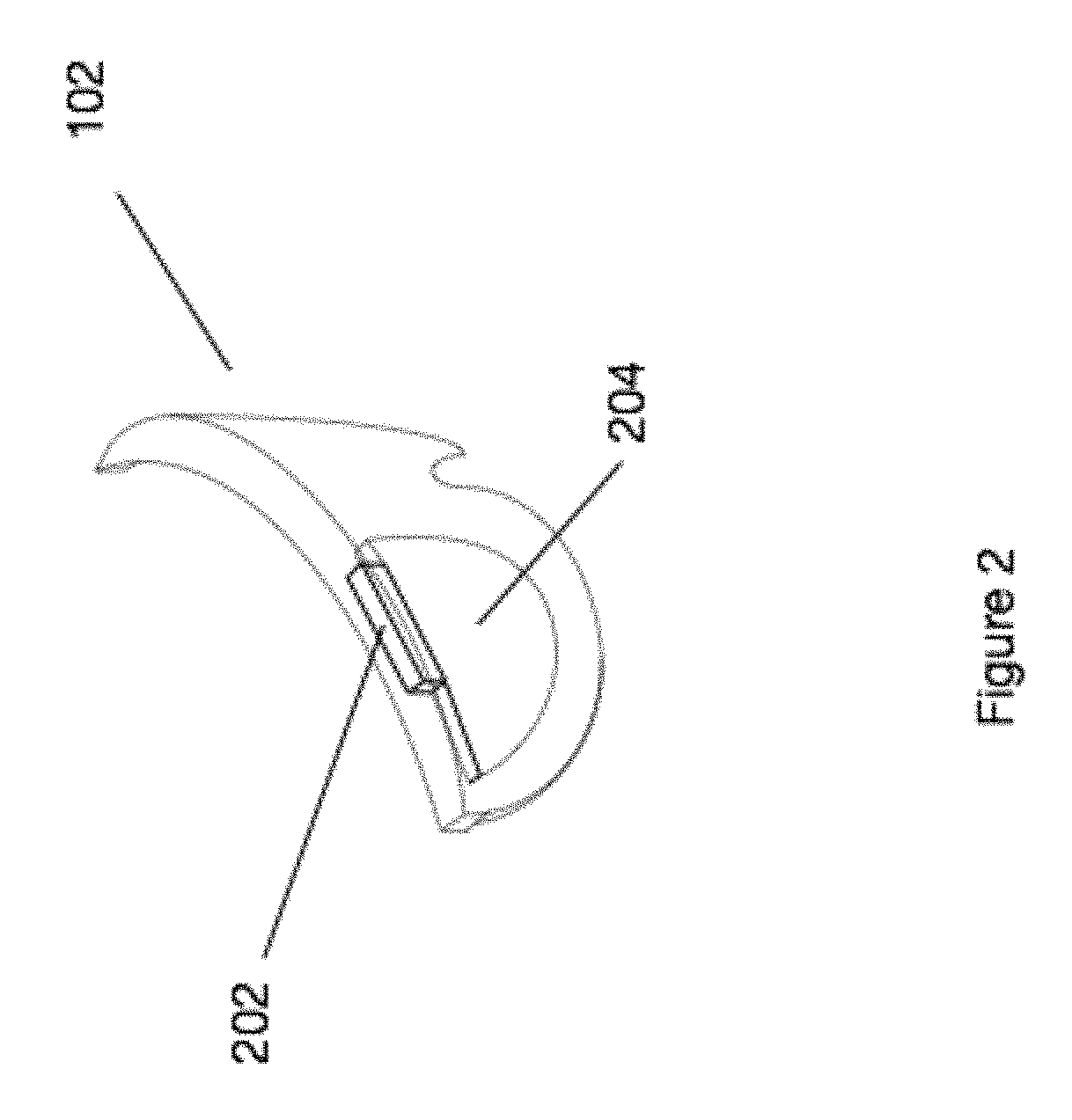
FIG. 2 illustrates a head worn computing system with optical system in accordance with the principles of the present invention.
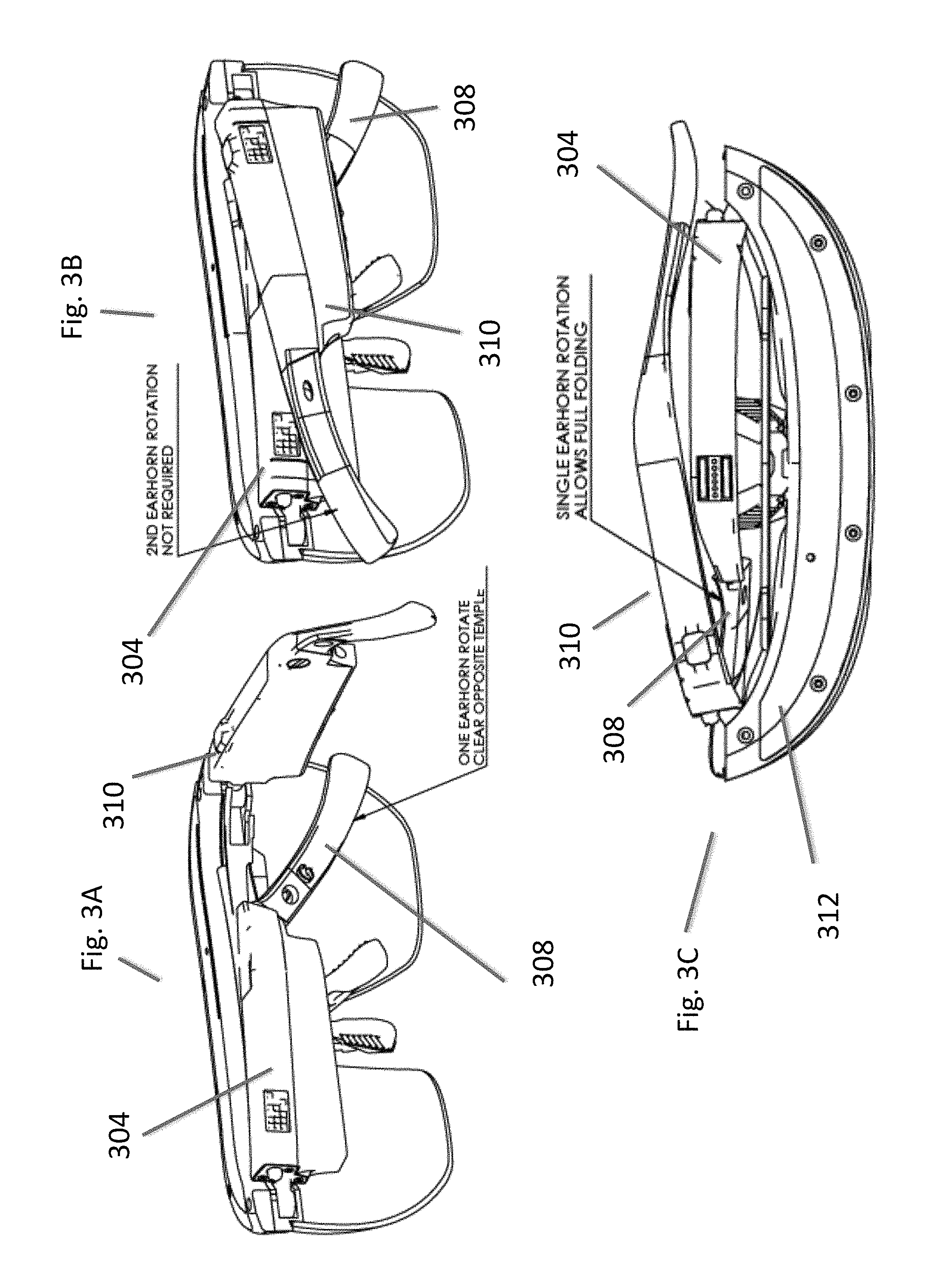
FIG. 3A, FIG. 3B, and FIG. 3C illustrate three views of a head worn computer in accordance with the principles of the present invention.
FIG. 4 illustrates a temple and ear horn in accordance with the principles of the present invention.
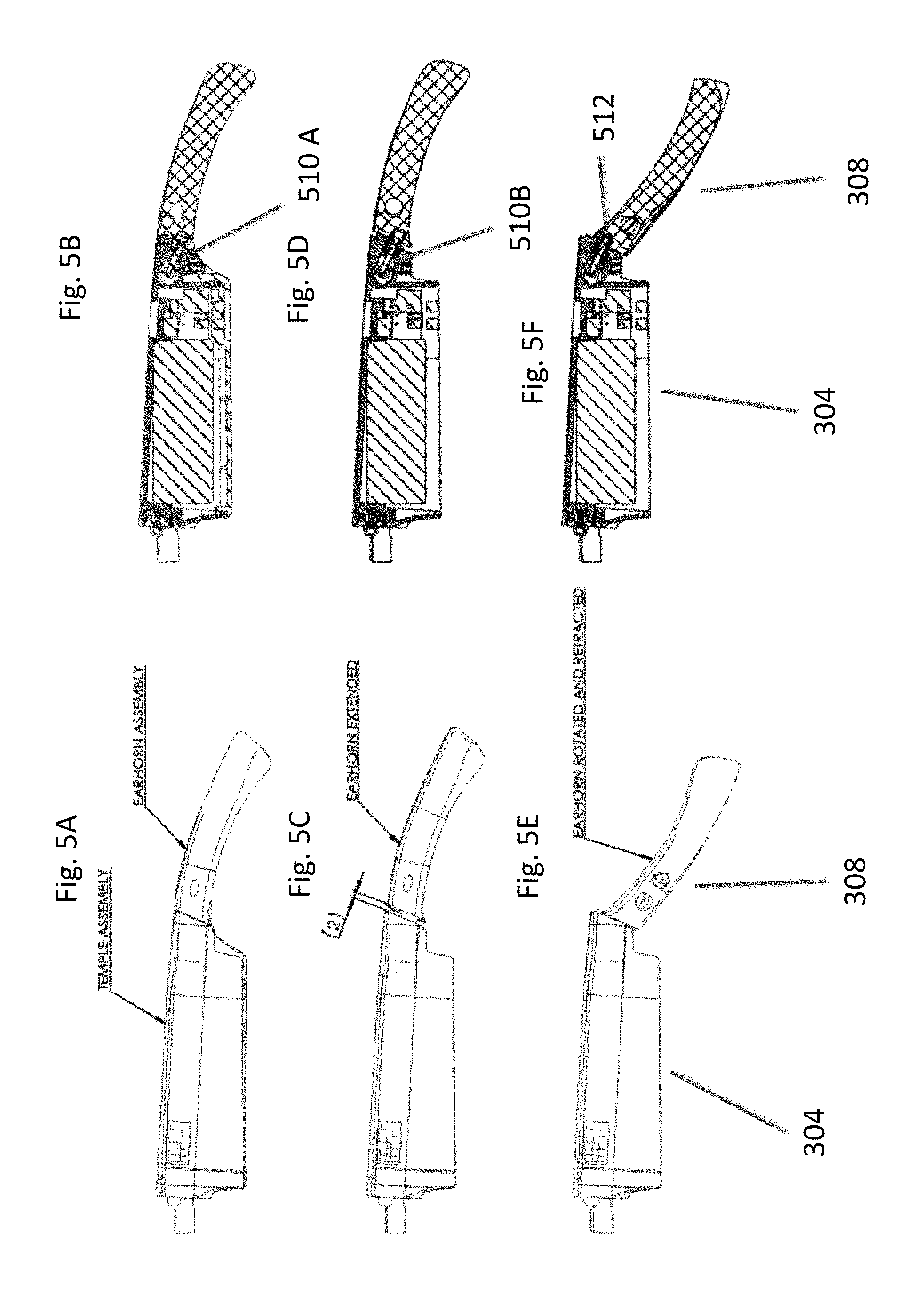
FIG. 5A, FIG. 5B, FIG. 5C, FIG. 5D, FIG. 5E. and FIG. 5F illustrate a temple and ear horn assembly in various states in accordance with the principles of the present invention.
FIG. 6 illustrates an adjustable nose bridge assembly in accordance with the principles of the present invention.
FIG. 7 illustrates an adjustable nose bridge assembly in accordance with the principles of the present invention.
FIG. 8 illustrates speaker assemblies for head-worn computers in accordance with the principles of the present invention.
FIG. 9 illustrates a stiff ear horn with a touch pad for a head-worn computer in accordance with the principles of the present invention.
While the invention has been described in connection with certain preferred embodiments, other embodiments would be understood by one of ordinary skill in the art and are encompassed herein.
DETAILED DESCRIPTION OF THE PREFERRED EMBODIMENT(S)
Aspects of the present invention relate to head-worn computing ("HWC") systems. HWC involves, in some instances, a system that mimics the appearance of head-worn glasses or sunglasses. The glasses may be a fully developed computing platform, such as including computer displays presented in each of the lenses of the glasses to the eyes of the user. In embodiments, the lenses and displays may be configured to allow a person wearing the glasses to see the environment through the lenses while also seeing, simultaneously, digital imagery, which forms an overlaid image that is perceived by the person as a digitally augmented image of the environment, or augmented reality ("AR").
HWC involves more than just placing a computing system on a person's head. The system may need to be designed as a lightweight, compact and fully functional computer display, such as wherein the computer display includes a high resolution digital display that provides a high level of emersion comprised of the displayed digital content and the see-through view of the environmental surroundings. User interfaces and control systems suited to the HWC device may be required that are unlike those used for a more conventional computer such as a laptop. For the HWC and associated systems to be most effective, the glasses may be equipped with sensors to determine environmental conditions, geographic location, relative positioning to other points of interest, objects identified by imaging and movement by the user or other users in a connected group, and the like. The HWC may then change the mode of operation to match the conditions, location, positioning, movements, and the like, in a method generally referred to as a contextually aware HWC. The glasses also may need to be connected, wirelessly or otherwise, to other systems either locally or through a network. Controlling the glasses may be achieved through the use of an external device, automatically through contextually gathered information, through user gestures captured by the glasses sensors, and the like. Each technique may be further refined depending on the software application being used in the glasses. The glasses may further be used to control or coordinate with external devices that are associated with the glasses.
Referring to FIG. 1, an overview of the HWC system 100 is presented. As shown, the HWC system 100 comprises a HWC 102, which in this instance is configured as glasses to be worn on the head with sensors such that the HWC 102 is aware of the objects and conditions in the environment 114. In this instance, the HWC 102 also receives and interprets control inputs such as gestures and movements 116 of body parts of a user. The HWC 102 may communicate with external user interfaces 104. The external user interfaces 104 may provide a physical user interface to take control instructions from a user of the HWC 102 and the external user interfaces 104 and the HWC 102 may communicate bi-directionally to affect the user's command and provide feedback to the external device 108. The HWC 102 may also communicate bi-directionally with externally controlled or coordinated local devices 108. For example, an external user interface 104 may be used in connection with the HWC 102 to control an externally controlled or coordinated local device 108. The externally controlled or coordinated local device 108 may provide feedback to the HWC 102 and a customized GUI may be presented in the HWC 102 based on the type of device or specifically identified device 108. The HWC 102 may also interact with remote devices and information sources 112 through a network connection 110. Again, the external user interface 104 may be used in connection with the HWC 102 to control or otherwise interact with any of the remote devices 108 and information sources 112 in a similar way as when the external user interfaces 104 are used to control or otherwise interact with the externally controlled or coordinated local devices 108. Similarly, HWC 102 may interpret gestures 116 (e.g captured from forward, downward, upward, rearward facing sensors such as camera(s), range finders, IR sensors, etc.) or environmental conditions sensed in the environment 114 to control either local or remote devices 108 or 112.
We will now describe each of the main elements depicted on FIG. 1 in more detail; however, these descriptions are intended to provide general guidance and should not be construed as limiting. Additional description of each element may also be further described herein.
The HWC 102 is a computing platform intended to be worn on a person's head. The HWC 102 may take many different forms to fit many different functional requirements. In some situations, the HWC 102 will be designed in the form of conventional glasses. The glasses may or may not have active computer graphics displays. In situations where the HWC 102 has integrated computer displays the displays may be configured as see-through displays such that the digital imagery can be overlaid with respect to the user's view of the environment 114. There are a number of see-through optical designs that may be used, including ones that have a reflective display (e.g. LCoS, DLP), emissive displays (e.g. OLED, LED), hologram, TIR waveguides, and the like. In embodiments, lighting systems used in connection with the display optics may be solid state lighting systems, such as LED, OLED, quantum dot, quantum dot LED, etc. In addition, the optical configuration may be monocular or binocular. It may also include vision corrective optical components. In embodiments, the optics may be packaged as contact lenses. In other embodiments, the HWC 102 may be in the form of a helmet with a see-through shield, sunglasses, safety glasses, goggles, a mask, fire helmet with see-through shield, police helmet with see through shield, military helmet with see-through shield, utility form customized to a certain work task (e.g. inventory control, logistics, repair, maintenance, etc.), and the like.
The HWC 102 may also have a number of integrated computing facilities, such as an integrated processor, integrated power management, communication structures (e.g. cell net, WiFi, Bluetooth, local area connections, mesh connections, remote connections (e.g. client server, etc.)), and the like. The HWC 102 may also have a number of positional awareness sensors, such as GPS, electronic compass, altimeter, tilt sensor, IMU, and the like. It may also have other sensors such as a camera, rangefinder, hyper-spectral camera, Geiger counter, microphone, spectral illumination detector, temperature sensor, chemical sensor, biologic sensor, moisture sensor, ultrasonic sensor, and the like.
The HWC 102 may also have integrated control technologies. The integrated control technologies may be contextual based control, passive control, active control, user control, and the like. For example, the HWC 102 may have an integrated sensor (e.g. camera) that captures user hand or body gestures 116 such that the integrated processing system can interpret the gestures and generate control commands for the HWC 102. In another example, the HWC 102 may have sensors that detect movement (e.g. a nod, head shake, and the like) including accelerometers, gyros and other inertial measurements, where the integrated processor may interpret the movement and generate a control command in response. The HWC 102 may also automatically control itself based on measured or perceived environmental conditions. For example, if it is bright in the environment the HWC 102 may increase the brightness or contrast of the displayed image. In embodiments, the integrated control technologies may be mounted on the HWC 102 such that a user can interact with it directly. For example, the HWC 102 may have a button(s), touch capacitive interface, and the like.
As described herein, the HWC 102 may be in communication with external user interfaces 104. The external user interfaces may come in many different forms. For example, a cell phone screen may be adapted to take user input for control of an aspect of the HWC 102. The external user interface may be a dedicated UI, such as a keyboard, touch surface, button(s), joy stick, and the like. In embodiments, the external controller may be integrated into another device such as a ring, watch, bike, car, and the like. In each case, the external user interface 104 may include sensors (e.g. IMU, accelerometers, compass, altimeter, and the like) to provide additional input for controlling the HWD 104.
As described herein, the HWC 102 may control or coordinate with other local devices 108. The external devices 108 may be an audio device, visual device, vehicle, cell phone, computer, and the like. For instance, the local external device 108 may be another HWC 102, where information may then be exchanged between the separate HWCs 108.
Similar to the way the HWC 102 may control or coordinate with local devices 106, the HWC 102 may control or coordinate with remote devices 112, such as the HWC 102 communicating with the remote devices 112 through a network 110. Again, the form of the remote device 112 may have many forms. Included in these forms is another HWC 102. For example, each HWC 102 may communicate its GPS position such that all the HWCs 102 know where all of HWC 102 are located.
FIG. 2 illustrates a HWC 102 with an optical system that includes an upper optical module 202 and a lower optical module 204. While the upper and lower optical modules 202 and 204 will generally be described as separate modules, it should be understood that this is illustrative only and the present invention includes other physical configurations, such as that when the two modules are combined into a single module or where the elements making up the two modules are configured into more than two modules. In embodiments, the upper module 202 includes a computer controlled display (e.g. LCoS, DLP, OLED, etc.) and image light delivery optics. In embodiments, the lower module includes eye delivery optics that are configured to receive the upper module's image light and deliver the image light to the eye of a wearer of the HWC. In FIG. 2, it should be noted that while the upper and lower optical modules 202 and 204 are illustrated in one side of the HWC such that image light can be delivered to one eye of the wearer, that it is envisioned by the present invention that embodiments will contain two image light delivery systems, one for each eye. It should also be noted that while many embodiments refer to the optical modules as "upper" and "lower" it should be understood that this convention is being used to make it easier for the reader and that the modules are not necessarily located in an upper-lower relationship. For example, the image generation module may be located above the eye delivery optics, below the eye delivery optics, on a side of the eye delivery optics, or otherwise positioned to satisfy the needs of the situation and/or the HWC 102 mechanical and optical requirements.
An aspect of the present invention relates to the mechanical and electrical construction of a side arm of a head worn computer. In general, when a head worn computer takes the form of glasses, sun-glasses, certain goggles, or other such forms, two side arms are included for mounting and securing the had worn computer on the ear's of a person wearing the head worn computer. In embodiments, the side arms may also contain electronics, batteries, wires, antennas, computer processors, computer boards, etc. In embodiments, the side arm may include two or more sub assemblies. For example, as will be discussed in more detail below, the side arm may include a temple section and an ear horn section. The two sections may, for example, be mechanically arranged to allow an ear horn section to move such that both side arms can fold into a closed position.
FIG. 3A, FIG. 3B and FIG. 3C illustrate three separate views of a head worn computer 102 according to the principles of the present invention. Turning to the head worn computer illustrated as FIG. 3A, one side arm of the HWC 102 is folded into its closed position. The ear horn section 308 of the side arm is rotated relative to its temple section 304 to create space relative to the other side arm 310 so when the other side arm is moved into its closed position it can fully close. In a situation where the ear horn did not rotate to create the space (not illustrated) the ear horn would physically interfere with the other side arm 310, when the side arm was in the closed position, and prevent the other side arm 310 from fully closing. The HWC FIG. 3B view illustrates the HWC FIG. 3B with both side arms folded into a fully closed position. Note that the ear horn 308 is in the rotated position with respect to its temple section 304 such that the other arm 310 closed without interfering with the ear horn 308. The HWC FIG. 3C view also illustrates both arms in closed positions with the ear horn 308 rotated to create the space for the other arm 310 to fully close. FIG. 3C also illustrates a portion of the HWC 102 where electronics may be housed in a top mount 312. The top mount may contain electronics, sensors, optics, processors, memory, radios, antennas, etc.
FIG. 4 illustrates a side arm configuration in accordance with the principles of the present invention. In this embodiment, the side arm includes two sub assemblies: the temple section 304 and the ear horn 308. FIG. 4 illustrates two views of the side arm assembly, one from an outer perspective and one from a sectioned perspective. The ear horn includes a pin 402 that is designed to fit into a hole 404 and to be secured by connector 408. The connector 408 is rotatable and in one position locks the pin 402 in place and in another position unsecures the pin 402 such that the ear horn 308 can be removed and re-attached to the temple section 304. This allows the detachment and re-attachment of the ear horn 308 from the temple section 304. This also allows for the sale of different ear horns 308 for replacement, of which a variety of colors and patterns may be offered. In embodiments, the temple section 304 may include a battery compartment 410 and other electronics, wires, sensors, processors, etc.
FIG. 5A, FIG. 5B, FIG. 5C, FIG. 5D, FIG. 5E. and FIG. 5F illustrate several views of a HWC side arm with temple 304 and ear horn 308 sections. The views include outer perspectives and cross sections as well as various states of the security of the ear horn 308 with the temple section 304. One embodiment of an outer perspective and cross-section of a temple assembly and earhorn assembly is shown in FIG. 5A and FIG. 5B, respectively, including connector and pin assembly 510A, wherein the ear horn is in its final secured position and ready to be put on the head of a user FIG. 5C and FIG. 5D illustrate the ear horn 308 and the temple section 304 in a secure, but separated and un-rotated position. The same pin 402 and connector 408 system described in connection with FIG. 4 is illustrated in the cross sections of FIG. 5E and FIG. 5F at connector and pin assembly 512. In the secured un-rotated position the pin is pulled internally within the temple section firmly such that it stays in place. FIG. 5C and FIG. 5D illustrate a state where the ear horn 308 is separated from the temple section 304. This state is achieved when pressure is used to pull on the ear horn 308. In embodiments, the pressure is exerted by a user pulling on the ear horn 308, which compresses a spring in the connector and pin assembly 510B that is mechanically associated with the pin 402 in the ear horn 308. The mechanism uses the spring to maintain pressure on the pin 402 to maintain connection with the connector 408 when the connector 408 is in a position to lock the pin 402 in position. FIG. 5E and FIG. 5F illustrates a state where, after the ear horn 308 has been pulled into the state described in connection with FIG. 5C and FIG. 5D, the ear horn 308 is rotated about the pin 402. This puts the ear horn 308 in a rotated position as described herein such that the first arm, with this rotated ear horn 308, does not interfere with the closure of the other arm 310 when the two arms are folded into the closed position. FIG. 5E and FIG. 5F illustrates the connector and pin assembly as continuing to secure the ear horn 308 to the temple 304 in the rotated position.
An aspect of the present invention relates to an adjustable nose bridge. An adjustable nose bridge may be important with head worn computers, especially those with computer displays, to ensure comfort and alignment of the displays and/or other portions of the head worn computer. FIG. 6 illustrates a HWC 102 with an adjustable nose bridge 602. The nose bridge is adjustable through a mechanism in the HWC 102. In embodiments, the mechanism includes a fixed notched attachment 604, a movable pin 608 adapted to fit into the notches of the notched attachment 604, and a selection device 610 that is attached to the movable pin 608. The movable pin 608 and nose bridge 602 are connected such that the as the movable pin 608 shifts in position the nose bridge 602 moves in position as well. The selection device 610 causes the movable pin 608 to engage and disengage with the fixed notched attachment 604 when presses and allowed to retract. As illustrated in FIG. 6, the selection device 610 is not in a pressed position so the movable pin 608 is engaged with the notched attachment 604 such that the nose bridge is securely attached in a stable position. FIG. 7 illustrates a scenario where the selection device is pressed, or activated, such that the moveable pin 608 is no longer engaged with the fixed notched attachment 604. This allows the nose bridge 602 to move up and down with respect to the rest of the HWC 102. Once the movable pin 608 aligns with a notch of the notched attachment 604, the two parts may engage to re-secure the nose bridge in the HWC 102.
In embodiments, a side arm of the HWC 102 may include an audio jack (not shown) and the audio jack may be magnetically attachable to the side arm. For example, the temple section 304 or ear horn section 308 may have a magnetically attachable audio jack with audio signal wires associated with an audio system in the HWC 102. The magnetic attachment may include one or more magnets on one end (e.g. on the head phone end or the side arm end) and magnetically conductive material on the other end. In other embodiments, both ends of the attachment may have magnets, of opposite polarization, to create a stronger magnetic bond for the headphone). In embodiments, the audio signal wires or magnetic connection may include a sensor circuit to detect when the headphone is detached from the HWC 102. This may be useful in situations where the wearer is wearing the headphones during a period when there is not constant audio processing (e.g. listening for people to talk with periods of silence). In embodiments, the other side's headphone may play a tone, sound, signal, etc. in the event a headphone is detached. In embodiments, an indication of the detachment may be displayed in the computer display.
In embodiments, the HWC 102 may have a vibration system that vibrates to alert the wearer of certain sensed conditions. In embodiments, the vibration system (e.g. an actuator that moves quickly to cause vibration in the HWC 102) may be mounted in a side arm (e.g. the temple section 304, or ear horn 308), in the top mount 312, etc. In embodiments, the vibration system may be capable of causing different vibration modes that may be indicative of different conditions. For example, the vibration system may include a multi-mode vibration system, piezo-electric vibration system, variable motor, etc., that can be regulated through computer input and a processor in the HWC 102 may send control signals to the vibration system to generate an appropriate vibration mode. In embodiments, the HWC 102 may be associated with other devices (e.g. through Bluetooth, WiFi, etc.) and the vibratory control signals may be associated with sensors associated with the other device. For example, the HWC 102 may be connected to a car through Bluetooth such that sensor(s) in the car can cause activation of a vibration mode for the vibration system. The car, for example, may determine that a risk of accident is present (e.g. risk of the driver falling asleep, car going out of its lane, a car in front of the wearer is stopped or slowing, radar in the car indicates a risk, etc.) and the car's system may then send a command, via the Bluetooth connection, to the HWC 102 to cause a vibratory tone to be initiated in the HWC 102.
Another aspect of the present invention relates to a removable and replaceable speaker assembly for a HWC 102. There are times when different speaker types are desired or when a speaker may malfunction. It is therefore desirable to have a speaker assembly that is removable and replaceable by the user. To facilitate the removal and reattachment of the speaker assembly a magnetic or magnetic attachment system may be included. For example, the speaker assembly and head-worn computer may include magnetic elements such that the speaker can be removed by exerting pressure and replaced by getting the two sections close to one another. In another example, the speaker or head-worn computer may have a button, slider, etc. that can be interacted with to remove the speaker. In embodiments, the speaker assembly may have a form factor of an ear bud, ear phone, head phone, head set, external ear speaker, etc. In embodiments, the speaker assembly may include a vibratory system to provide haptic feedback to the user. In embodiments, such a removable and replaceable speaker system may be provided to both of the user's ears.
FIG. 8 illustrates several embodiments where HWC 102's are associated with speaker systems. Earbud 802 may be removably attached to the HWC 102 with a magnetic system or mechanical system or combination thereof. Speaker 804 may also be removably attached to the HWC102 in a similar way. The speaker 804 may be positioned to emit sound towards the user's ear but not actually be positioned in the ear. This configuration may provide for greater environmental hearing for the user as the ear would not be blocked by an ear bud, head phone, etc. The speaker 804 may generate audio waves and/or ultrasonic waves that are converted into audio when they are emitted through the air. When ultrasonic transducers are used, more than one frequency transducer may be included. See http://en.m.wikipedia.org/wiki/Sound from ultrasound and http://www.holosonics.com for references on generating sound from ultrasound. The speaker and/or piezo vibratory system 808 is depicted as integrated into the temple. In embodiments, this module may be integrated such that it can be removed and replaced and it may also be adapted such that it does not hang below the temple piece. Each of the removable and replaceable speaker systems described herein may include a vibratory system (e.g. piezo electric circuit that is controlled by the HWC 102.
In embodiments, a head-worn computer may include a temple portion mechanically secured to a computer display and adapted to position the computer display in front of an eye of a user, and the temple portion including a speaker attachment, wherein the speaker attachment is adapted to securely position a speaker assembly and electrically associate the speaker assembly with electronics internal to the head-worn computer and facilitate the user's release and re-securing of the speaker assembly with the temple portion. The speaker attachment may include a magnetic element, moveable mechanical element, etc. or combination thereof to secure and unsecure the speaker system from the HWC 102. The speaker assembly may have a form factor adapted to be inserted into an outer ear of the user, cover at least a portion of an outer ear of the user, cover substantially all of an outer ear of the user, to position the speaker under the temple assembly and above an ear of the user, to position a speaker under the temple assembly and in front of an ear of the user, angle the speaker towards the ear, etc. The speaker system may further have a vibratory system to provide haptic feedback to the user. The haptic feedback may be coordinated with a game being presented in the computer display, an application running on the HWC 102, etc. In embodiments, a vibratory system is provided in both speaker systems to provide controllable haptic feedback in stereo and/or on both or either side of the user's head.
In embodiments, the connection between the speaker system and the HWC 102 may be positioned other than under the temple section. It may be positioned on a side, top, bottom, end of a section of the side arm, for example. It may be positioned on the front bridge, for example. In embodiments, the speaker system may be connected to a top or side portion and the speaker may be further positioned to face forward, away from the user's ear. This may be a useful configuration for providing sound to others. For example, such a configuration may be used when the user wants to provide translations to a person nearby. The user may speak in a language, have the language translated, and then spoken through the forward facing speakers.
The removable nature of the speaker systems may be desirable for breakaway situations so a snag does not tear the glasses from the user or pull hard on the user's ear. The removable nature may also be useful for modularity configurations where the user wants to interchange speaker types or attach other accessories. For example, the user may want ear buds at one point and an open ear speaker configuration at another point and the user may be able to make the swap with ease given this configuration. The port on the HWC 102 may also be adapted for other accessories that include lights or sensors for example. The accessory may have an ambient light sensor to assist with the control of the lighting and contrast systems used in the HWC 102 displays, for example. In embodiments, the speaker port may be used as a charging port for the HWC 102 or data port for the HWC 102.
Another aspect of the present invention relates to securing the head-worn computer 102 to the user's head in a way that the computer does not slip down the nose of the user, due to the extra front weight of the HWC 102, but does not create discomfort for the user. While some have designed systems that use lateral force between the two side arms to squeeze the HWC arms on the sides of the user's head, this solution tends to cause comfort problems. The squeeze on the user's head has to be relatively high, as compared to non-computer glasses, to maintain enough pressure to overcome the additional weight in the front of the glasses and this high pressure tends to cause comfort issues. In embodiments of the present invention, a substantially stiff ear horn is provided and the back end of the ear horn wraps around the user's head and touches the user's head. The touch point is towards the back of the user's head such that it provides a point or area of counteracting force for the HWC 102 if it tries to pull forward or down the user's nose due to the front weight of the HWC 102. In embodiments, the end of the ear horn, or a section near the end, has a touch pad. The touch pad may be made of soft material so it is comfortable on the back of the user's head. In embodiments, the touch pad may be mounted such that it has angular flexibility. The angular flexibility allows the touch pad to better align with the touch point on the user's head so it can provide the counteractive force but spread the force over an area for greater comfort.
In embodiments, a head-worn computer is provided and has a see-through computer display configured to be mounted on the head of a user; a side arm configured to secure the see-through computer display to the user's head, the side arm further configured to be positioned to lay against the user's head proximate an ear of the user; and the side arm including a stiff member extending behind the ear of the user, contoured to substantially follow a curvature of the user's head behind the ear of the user, and to touch a portion of the user's head towards the rear of the user's head such that the see-through computer display remains substantially secure in a position in front of an eye of the user.
In embodiments, the stiff member is removeably secured to a temple portion of the side arm (as described herein elsewhere). The stiff member may be telescopically adjustable to fit the user's head. The stiff member may be provided with a ratchet style securing mechanism for adjusting the telescopic adjustment. The stiff member may be provided with a rotatable style securing mechanism for adjusting the telescopic adjustment, or another style securing mechanism may be provided. The stiff member may touch a portion of the user's head at a rear end of the stiff member. The rear end of the stiff member may include a touch pad. The touch pad may be made of a soft material to increase the comfort and surface area of the touch area. The touch pad may be attached such that it has angular flexibility such that the touch pad changes position to increase a touch surface in contact with the rear of the user's head.
FIG. 9 illustrates a HWC 102 mounted on the head of a user. The HWC 102 has a see-through optics module 204, a temple portion 304, a stiff ear horn 904 and a head-touch pad 902. As described herein elsewhere, the stiff ear horn 904 may be removable and replaceable. This can be useful when the exchange of ear horns from one type to another or one size to another is desired, for example. The stiff ear horn 904 may be made of aluminum, aluminum tubing, carbon fiber, or other material that is relatively stiff. The stiffness should be of a level that provides for lateral inflexibility such that the touch pad 902 can exert counteracting force with a high rear facing vector. Too much flexibility in the stiff ear horn 904 can detract from the rear-facing vector of force when the weight of the HWC 102 is pulling forward/down the nose. In embodiments, several different lengths, shapes, stiffnesses, etc. of stiff ear horn 904 may be provided so the user can select the set that best serves his purpose. The head-touch pad 902 may be made of a soft material, malleable material, etc. to provide comfort to the user and to increase the head touch surface. The head-touch pad 902 may also be mounted in such a way that the head-touch pad 902 can flex and/or change angle as it is pressed upon. The head-touch pad 902 may, for example, be mounted on the stiff ear horn 904 with a hinge or pivot mechanism such that the head-touch pad 902 self aligns with the user's head when the HWC 102 is put on the user's head. This configuration may increase the touch surface area between the head-touch pad 902 and the user's head and generate a larger counteracting force to prevent the slipping or moving of the HWC 102.
In embodiments, the side arms of the HWC 102 are designed to exert inward lateral pressure on the user's head, but the lateral pressure is reduced so it is not uncomfortable, along with having stiff side arms 904 and head-touch pads 902. In these embodiments, the ear horns 904 and head touch pads 902 cause significant counteracting forces in addition to the counteracting forces applied through the inward lateral forces applied by the side arms.
Although embodiments of HWC have been described in language specific to features, systems, computer processes and/or methods, the appended claims are not necessarily limited to the specific features, systems, computer processes and/or methods described. Rather, the specific features, systems, computer processes and/or and methods are disclosed as non-limited example implementations of HWC. All documents referenced herein are hereby incorporated by reference.
* * * * *
References
D00000
D00001
D00002
D00003
D00004
D00005
D00006
D00007
D00008
D00009
XML
uspto.report is an independent third-party trademark research tool that is not affiliated, endorsed, or sponsored by the United States Patent and Trademark Office (USPTO) or any other governmental organization. The information provided by uspto.report is based on publicly available data at the time of writing and is intended for informational purposes only.
While we strive to provide accurate and up-to-date information, we do not guarantee the accuracy, completeness, reliability, or suitability of the information displayed on this site. The use of this site is at your own risk. Any reliance you place on such information is therefore strictly at your own risk.
All official trademark data, including owner information, should be verified by visiting the official USPTO website at www.uspto.gov. This site is not intended to replace professional legal advice and should not be used as a substitute for consulting with a legal professional who is knowledgeable about trademark law.