Ultrasonic transducer for surgical instrument
Messerly , et al. Sept
U.S. patent number 10,420,580 [Application Number 15/679,948] was granted by the patent office on 2019-09-24 for ultrasonic transducer for surgical instrument. This patent grant is currently assigned to Ethicon LLC. The grantee listed for this patent is Ethicon LLC. Invention is credited to Jeffrey L. Aldridge, Brian D. Black, William E. Clem, Frederick Estera, Kevin L. Houser, Stephen M. Leuck, Jeffrey D. Messerly, Jerome R. Morgan, William A. Olson, Foster B. Stulen.


View All Diagrams
| United States Patent | 10,420,580 |
| Messerly , et al. | September 24, 2019 |
Ultrasonic transducer for surgical instrument
Abstract
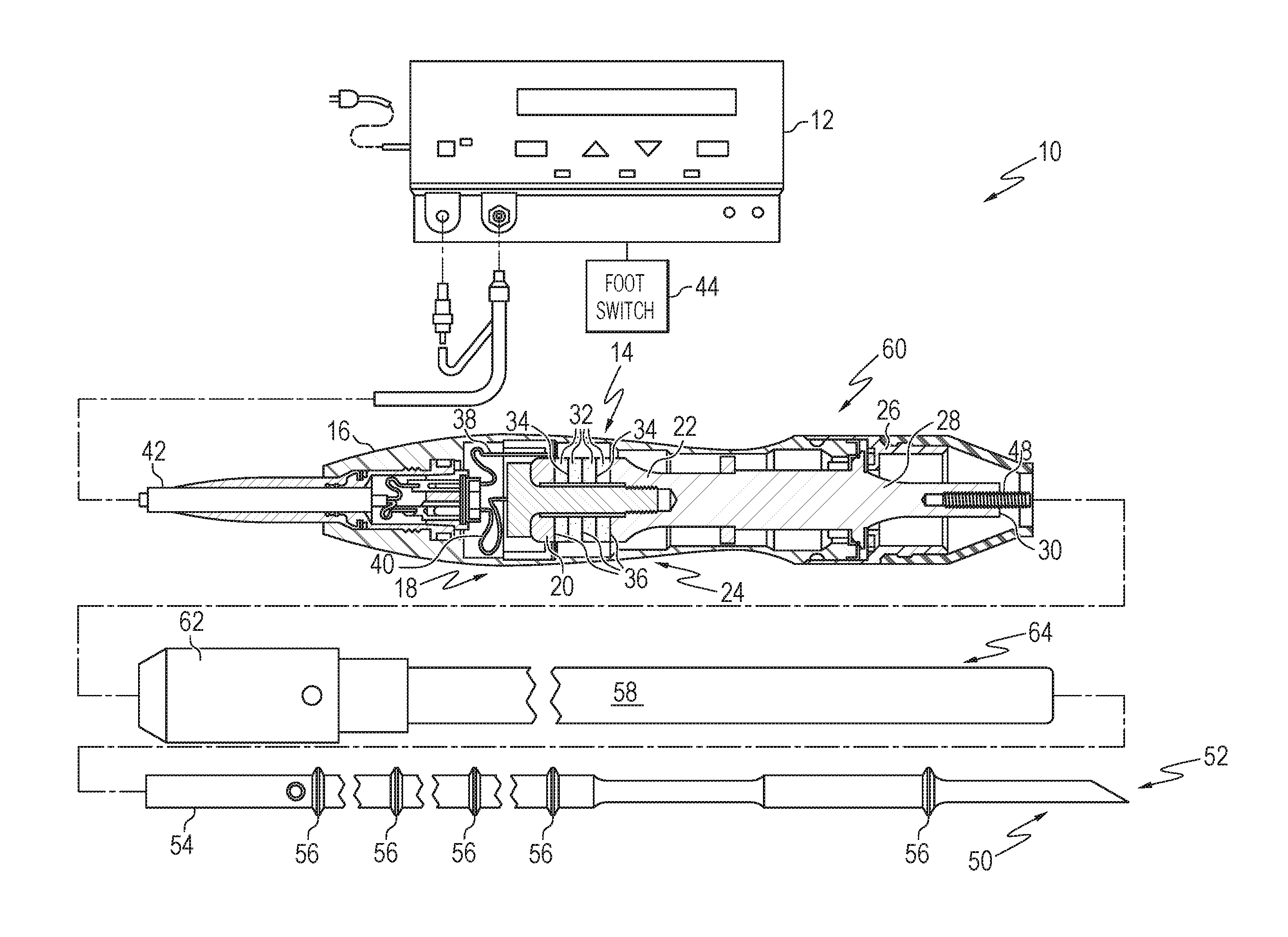
Disclosed is an ultrasonic medical device that may include a surgical tool having a proximal end, an end effector, and a waveguide between them, a first transducer in mechanical communication with a first face of the surgical tool, and a second transducer in mechanical communication with an opposing face of the surgical tool, opposite the first transducer. The first transducer and the second transducer are configured to operate in a D31 mode with respect to the waveguide of the surgical tool. Another aspect comprises a method of fabricating the ultrasonic medical device, in which the surgical tool is machined from a portion of a flat metal stock so that the surgical tool has a longitudinal axis oriented at an angle with respect to a grain direction of the flat metal stock thereby optimizing an operational characteristic of the surgical tool.
| Inventors: | Messerly; Jeffrey D. (Cincinnati, OH), Black; Brian D. (Loveland, OH), Olson; William A. (Lebanon, OH), Stulen; Foster B. (Mason, OH), Estera; Frederick (Cincinnati, OH), Clem; William E. (Bozeman, MT), Morgan; Jerome R. (Cincinnati, OH), Aldridge; Jeffrey L. (Lebanon, OH), Leuck; Stephen M. (Milford, OH), Houser; Kevin L. (Springboro, OH) | ||||||||||
|---|---|---|---|---|---|---|---|---|---|---|---|
| Applicant: |
|
||||||||||
| Assignee: | Ethicon LLC (Guaynabo,
PR) |
||||||||||
| Family ID: | 61240171 | ||||||||||
| Appl. No.: | 15/679,948 | ||||||||||
| Filed: | August 17, 2017 |
Prior Publication Data
| Document Identifier | Publication Date | |
|---|---|---|
| US 20180055530 A1 | Mar 1, 2018 | |
Related U.S. Patent Documents
| Application Number | Filing Date | Patent Number | Issue Date | ||
|---|---|---|---|---|---|
| 62379550 | Aug 25, 2016 | ||||
| Current U.S. Class: | 1/1 |
| Current CPC Class: | H01L 41/0835 (20130101); A61N 7/02 (20130101); A61B 17/320068 (20130101); A61B 17/00234 (20130101); H01L 41/0536 (20130101); H01L 41/0986 (20130101); B29C 65/4805 (20130101); H01L 41/083 (20130101); A61B 2017/00402 (20130101); A61B 2017/00017 (20130101); A61B 2017/320082 (20170801); A61B 2017/22027 (20130101); A61B 2018/00565 (20130101); B29L 2031/7546 (20130101); A61B 2017/00526 (20130101); A61B 2018/00589 (20130101); A61B 2017/320088 (20130101); A61B 2017/294 (20130101); A61B 17/1628 (20130101); A61B 2017/00477 (20130101); A61B 2017/320074 (20170801); A61B 2017/320089 (20170801); A61B 2018/00595 (20130101); A61B 2017/32007 (20170801); A61B 2017/0088 (20130101); A61B 2017/320098 (20170801) |
| Current International Class: | H01L 41/09 (20060101); B29C 65/48 (20060101); A61B 17/32 (20060101); A61N 7/02 (20060101); H01L 41/053 (20060101); H01L 41/083 (20060101); A61B 17/00 (20060101); A61B 17/16 (20060101); A61B 17/22 (20060101); A61B 18/00 (20060101) |
| Field of Search: | ;310/323.01-323.21,324,330-332 |
References Cited [Referenced By]
U.S. Patent Documents
| 969528 | September 1910 | Disbrow |
| 1570025 | January 1926 | Young |
| 1813902 | July 1931 | Bovie |
| 2188497 | January 1940 | Calva |
| 2366274 | January 1945 | Luth et al. |
| 2425245 | August 1947 | Johnson |
| 2442966 | June 1948 | Wallace |
| 2458152 | January 1949 | Eakins |
| 2510693 | June 1950 | Green |
| 2597564 | May 1952 | Bugg |
| 2704333 | March 1955 | Calosi et al. |
| 2736960 | March 1956 | Armstrong |
| 2743726 | May 1956 | Grieshaber |
| 2748967 | June 1956 | Roach |
| 2845072 | July 1958 | Shafer |
| 2849788 | September 1958 | Creek |
| 2867039 | January 1959 | Zach |
| 2874470 | February 1959 | Richards |
| 2990616 | July 1961 | Balamuth et al. |
| RE25033 | August 1961 | Balamuth et al. |
| 3015961 | January 1962 | Roney |
| 3033407 | May 1962 | Alfons |
| 3053124 | September 1962 | Balamuth et al. |
| 3082805 | March 1963 | Royce |
| 3166971 | January 1965 | Stoecker |
| 3322403 | May 1967 | Murphy |
| 3432691 | March 1969 | Shoh |
| 3433226 | March 1969 | Boyd |
| 3489930 | January 1970 | Shoh |
| 3513848 | May 1970 | Winston et al. |
| 3514856 | June 1970 | Camp et al. |
| 3525912 | August 1970 | Wallin |
| 3526219 | September 1970 | Balamuth |
| 3554198 | January 1971 | Tatoian et al. |
| 3580841 | May 1971 | Cadotte et al. |
| 3606682 | September 1971 | Camp et al. |
| 3614484 | October 1971 | Shoh |
| 3616375 | October 1971 | Inoue |
| 3629726 | December 1971 | Popescu |
| 3636943 | January 1972 | Balamuth |
| 3668486 | June 1972 | Silver |
| 3702948 | November 1972 | Balamuth |
| 3703651 | November 1972 | Blowers |
| 3776238 | December 1973 | Peyman et al. |
| 3777760 | December 1973 | Essner |
| 3805787 | April 1974 | Banko |
| 3809977 | May 1974 | Balamuth et al. |
| 3830098 | August 1974 | Antonevich |
| 3854737 | December 1974 | Gilliam, Sr. |
| 3862630 | January 1975 | Balamuth |
| 3875945 | April 1975 | Friedman |
| 3885438 | May 1975 | Harris, Sr. et al. |
| 3900823 | August 1975 | Sokal et al. |
| 3918442 | November 1975 | Nikolaev et al. |
| 3924335 | December 1975 | Balamuth et al. |
| 3946738 | March 1976 | Newton et al. |
| 3955859 | May 1976 | Stella et al. |
| 3956826 | May 1976 | Perdreaux, Jr. |
| 4005714 | February 1977 | Hiltebrandt |
| 4012647 | March 1977 | Balamuth et al. |
| 4034762 | July 1977 | Cosens et al. |
| 4058126 | November 1977 | Leveen |
| 4074719 | February 1978 | Semm |
| 4085893 | April 1978 | Durley, III |
| 4156187 | May 1979 | Murry et al. |
| 4167944 | September 1979 | Banko |
| 4188927 | February 1980 | Harris |
| 4193009 | March 1980 | Durley, III |
| 4200106 | April 1980 | Douvas et al. |
| 4203430 | May 1980 | Takahashi |
| 4203444 | May 1980 | Bonnell et al. |
| 4220154 | September 1980 | Semm |
| 4237441 | December 1980 | van Konynenburg et al. |
| 4281785 | August 1981 | Brooks |
| 4300083 | November 1981 | Heiges |
| 4302728 | November 1981 | Nakamura |
| 4304987 | December 1981 | van Konynenburg |
| 4306570 | December 1981 | Matthews |
| 4314559 | February 1982 | Allen |
| 4445063 | April 1984 | Smith |
| 4463759 | August 1984 | Garito et al. |
| 4491132 | January 1985 | Aikins |
| 4492231 | January 1985 | Auth |
| 4494759 | January 1985 | Kieffer |
| 4504264 | March 1985 | Kelman |
| 4512344 | April 1985 | Barber |
| 4526571 | July 1985 | Wuchinich |
| 4535773 | August 1985 | Yoon |
| 4541638 | September 1985 | Ogawa et al. |
| 4545374 | October 1985 | Jacobson |
| 4545926 | October 1985 | Fouts, Jr. et al. |
| 4550870 | November 1985 | Krumme et al. |
| 4553544 | November 1985 | Nomoto et al. |
| 4562838 | January 1986 | Walker |
| 4574615 | March 1986 | Bower et al. |
| 4582236 | April 1986 | Hirose |
| 4617927 | October 1986 | Manes |
| 4633119 | December 1986 | Thompson |
| 4634420 | January 1987 | Spinosa et al. |
| 4640279 | February 1987 | Beard |
| 4641053 | February 1987 | Takeda |
| 4646738 | March 1987 | Trott |
| 4646756 | March 1987 | Watmough et al. |
| 4649919 | March 1987 | Thimsen et al. |
| 4662068 | May 1987 | Polonsky |
| 4674502 | June 1987 | Imonti |
| 4708127 | November 1987 | Abdelghani |
| 4712722 | December 1987 | Hood et al. |
| 4735603 | April 1988 | Goodson et al. |
| 4761871 | August 1988 | O'Connor et al. |
| 4808154 | February 1989 | Freeman |
| 4819635 | April 1989 | Shapiro |
| 4827911 | May 1989 | Broadwin et al. |
| 4830462 | May 1989 | Karny et al. |
| 4832683 | May 1989 | Idemoto et al. |
| 4836186 | June 1989 | Scholz |
| 4838853 | June 1989 | Parisi |
| 4844064 | July 1989 | Thimsen et al. |
| 4849133 | July 1989 | Yoshida et al. |
| 4850354 | July 1989 | McGurk-Burleson et al. |
| 4852578 | August 1989 | Companion et al. |
| 4860745 | August 1989 | Farin et al. |
| 4862890 | September 1989 | Stasz et al. |
| 4865159 | September 1989 | Jamison |
| 4867157 | September 1989 | McGurk-Burleson et al. |
| 4878493 | November 1989 | Pasternak et al. |
| 4880015 | November 1989 | Nierman |
| 4881550 | November 1989 | Kothe |
| 4896009 | January 1990 | Pawlowski |
| 4903696 | February 1990 | Stasz et al. |
| 4910389 | March 1990 | Sherman et al. |
| 4915643 | April 1990 | Samejima et al. |
| 4920978 | May 1990 | Colvin |
| 4922902 | May 1990 | Wuchinich et al. |
| 4936842 | June 1990 | D'Amelio et al. |
| 4954960 | September 1990 | Lo et al. |
| 4965532 | October 1990 | Sakurai |
| 4979952 | December 1990 | Kubota et al. |
| 4981756 | January 1991 | Rhandhawa |
| 4983160 | January 1991 | Steppe et al. |
| 5013956 | May 1991 | Kurozumi et al. |
| 5015227 | May 1991 | Broadwin et al. |
| 5020514 | June 1991 | Heckele |
| 5026370 | June 1991 | Lottick |
| 5026387 | June 1991 | Thomas |
| 5035695 | July 1991 | Weber, Jr. et al. |
| 5042707 | August 1991 | Taheri |
| 5061269 | October 1991 | Muller |
| 5084052 | January 1992 | Jacobs |
| 5099840 | March 1992 | Goble et al. |
| 5104025 | April 1992 | Main et al. |
| 5105117 | April 1992 | Yamaguchi |
| 5106538 | April 1992 | Barma et al. |
| 5108383 | April 1992 | White |
| 5109819 | May 1992 | Custer et al. |
| 5112300 | May 1992 | Ureche |
| 5123903 | June 1992 | Quaid et al. |
| 5126618 | June 1992 | Takahashi et al. |
| D327872 | July 1992 | McMills et al. |
| 5152762 | October 1992 | McElhenney |
| 5156633 | October 1992 | Smith |
| 5160334 | November 1992 | Billings et al. |
| 5162044 | November 1992 | Gahn et al. |
| 5163421 | November 1992 | Bernstein et al. |
| 5163537 | November 1992 | Radev |
| 5167619 | December 1992 | Wuchinich |
| 5167725 | December 1992 | Clark et al. |
| 5172344 | December 1992 | Ehrlich |
| 5174276 | December 1992 | Crockard |
| D332660 | January 1993 | Rawson et al. |
| 5176677 | January 1993 | Wuchinich |
| 5176695 | January 1993 | Dulebohn |
| 5184605 | February 1993 | Grzeszykowski |
| 5188102 | February 1993 | Idemoto et al. |
| D334173 | March 1993 | Liu et al. |
| 5190541 | March 1993 | Abele et al. |
| 5196007 | March 1993 | Ellman et al. |
| 5205459 | April 1993 | Brinkerhoff et al. |
| 5209719 | May 1993 | Baruch et al. |
| 5213103 | May 1993 | Martin et al. |
| 5213569 | May 1993 | Davis |
| 5214339 | May 1993 | Naito |
| 5217460 | June 1993 | Knoepfler |
| 5218529 | June 1993 | Meyer et al. |
| 5221282 | June 1993 | Wuchinich |
| 5222937 | June 1993 | Kagawa |
| 5226909 | July 1993 | Evans et al. |
| 5226910 | July 1993 | Kajiyama et al. |
| 5234428 | August 1993 | Kaufman |
| 5234436 | August 1993 | Eaton et al. |
| 5241236 | August 1993 | Sasaki et al. |
| 5241968 | September 1993 | Slater |
| 5242460 | September 1993 | Klein et al. |
| 5254129 | October 1993 | Alexander |
| 5257988 | November 1993 | L'Esperance, Jr. |
| 5258006 | November 1993 | Rydell et al. |
| 5261922 | November 1993 | Hood |
| 5263957 | November 1993 | Davison |
| 5264925 | November 1993 | Shipp et al. |
| 5275166 | January 1994 | Vaitekunas et al. |
| 5275607 | January 1994 | Lo et al. |
| 5275609 | January 1994 | Pingleton et al. |
| 5282800 | February 1994 | Foshee et al. |
| 5282817 | February 1994 | Hoogeboom et al. |
| 5285795 | February 1994 | Ryan et al. |
| 5285945 | February 1994 | Brinkerhoff et al. |
| 5290286 | March 1994 | Parins |
| 5300068 | April 1994 | Rosar et al. |
| 5304115 | April 1994 | Pflueger et al. |
| D347474 | May 1994 | Olson |
| 5307976 | May 1994 | Olson et al. |
| 5309927 | May 1994 | Welch |
| 5312023 | May 1994 | Green et al. |
| 5312425 | May 1994 | Evans et al. |
| 5318563 | June 1994 | Malis et al. |
| 5318564 | June 1994 | Eggers |
| 5318570 | June 1994 | Hood et al. |
| 5318589 | June 1994 | Lichtman |
| 5322055 | June 1994 | Davison et al. |
| 5324299 | June 1994 | Davison et al. |
| 5326013 | July 1994 | Green et al. |
| 5326342 | July 1994 | Pflueger et al. |
| 5330471 | July 1994 | Eggers |
| 5330502 | July 1994 | Hassler et al. |
| 5339723 | August 1994 | Huitema |
| 5342359 | August 1994 | Rydell |
| 5344420 | September 1994 | Hilal et al. |
| 5345937 | September 1994 | Middleman et al. |
| 5346502 | September 1994 | Estabrook et al. |
| 5353474 | October 1994 | Good et al. |
| 5357164 | October 1994 | Imabayashi et al. |
| 5357423 | October 1994 | Weaver et al. |
| 5359994 | November 1994 | Krauter et al. |
| 5361583 | November 1994 | Huitema |
| 5366466 | November 1994 | Christian et al. |
| 5368557 | November 1994 | Nita et al. |
| 5370645 | December 1994 | Klicek et al. |
| 5371429 | December 1994 | Manna |
| 5374813 | December 1994 | Shipp |
| D354564 | January 1995 | Medema |
| 5381067 | January 1995 | Greenstein et al. |
| 5383874 | January 1995 | Jackson et al. |
| 5387207 | February 1995 | Dyer et al. |
| 5387215 | February 1995 | Fisher |
| 5389098 | February 1995 | Tsuruta et al. |
| 5394187 | February 1995 | Shipp |
| 5395312 | March 1995 | Desai |
| 5395363 | March 1995 | Billings et al. |
| 5395364 | March 1995 | Anderhub et al. |
| 5396266 | March 1995 | Brimhall |
| 5396900 | March 1995 | Slater et al. |
| 5403312 | April 1995 | Yates et al. |
| 5403334 | April 1995 | Evans et al. |
| 5408268 | April 1995 | Shipp |
| 5409453 | April 1995 | Lundquist et al. |
| D358887 | May 1995 | Feinberg |
| 5411481 | May 1995 | Allen et al. |
| 5417709 | May 1995 | Slater |
| 5419761 | May 1995 | Narayanan et al. |
| 5421829 | June 1995 | Olichney et al. |
| 5423844 | June 1995 | Miller |
| 5428504 | June 1995 | Bhatla |
| 5429131 | July 1995 | Scheinman et al. |
| 5438997 | August 1995 | Sieben et al. |
| 5443463 | August 1995 | Stern et al. |
| 5445638 | August 1995 | Rydell et al. |
| 5445639 | August 1995 | Kuslich et al. |
| 5449370 | September 1995 | Vaitekunas |
| 5451220 | September 1995 | Ciervo |
| 5451227 | September 1995 | Michaelson |
| 5456684 | October 1995 | Schmidt et al. |
| 5458598 | October 1995 | Feinberg et al. |
| 5465895 | November 1995 | Knodel et al. |
| 5471988 | December 1995 | Fujio et al. |
| 5472443 | December 1995 | Cordis et al. |
| 5476479 | December 1995 | Green et al. |
| 5478003 | December 1995 | Green et al. |
| 5480409 | January 1996 | Riza |
| 5483501 | January 1996 | Park et al. |
| 5484436 | January 1996 | Eggers et al. |
| 5486162 | January 1996 | Brumbach |
| 5486189 | January 1996 | Mudry et al. |
| 5490860 | February 1996 | Middle et al. |
| 5496317 | March 1996 | Goble et al. |
| 5500216 | March 1996 | Julian et al. |
| 5501654 | March 1996 | Failla et al. |
| 5504650 | April 1996 | Katsui et al. |
| 5505693 | April 1996 | Mackool |
| 5507738 | April 1996 | Ciervo |
| 5509922 | April 1996 | Aranyi et al. |
| 5511556 | April 1996 | DeSantis |
| 5520704 | May 1996 | Castro et al. |
| 5522839 | June 1996 | Pilling |
| 5527331 | June 1996 | Kresch et al. |
| 5531744 | July 1996 | Nardella et al. |
| 5540681 | July 1996 | Strul et al. |
| 5540693 | July 1996 | Fisher |
| 5542916 | August 1996 | Hirsch et al. |
| 5553675 | September 1996 | Pitzen et al. |
| 5558671 | September 1996 | Yates |
| 5562609 | October 1996 | Brumbach |
| 5562610 | October 1996 | Brumbach |
| 5562659 | October 1996 | Morris |
| 5563179 | October 1996 | Stone et al. |
| 5569164 | October 1996 | Lurz |
| 5571121 | November 1996 | Heifetz |
| 5573424 | November 1996 | Poppe |
| 5573534 | November 1996 | Stone |
| 5577654 | November 1996 | Bishop |
| 5582618 | December 1996 | Chin et al. |
| 5584830 | December 1996 | Ladd et al. |
| 5591187 | January 1997 | Dekel |
| 5593414 | January 1997 | Shipp et al. |
| 5599350 | February 1997 | Schulze et al. |
| 5601601 | February 1997 | Tal et al. |
| 5603773 | February 1997 | Campbell |
| 5607436 | March 1997 | Pratt et al. |
| 5607450 | March 1997 | Zvenyatsky et al. |
| 5609573 | March 1997 | Sandock |
| 5611813 | March 1997 | Lichtman |
| 5618304 | April 1997 | Hart et al. |
| 5618307 | April 1997 | Donlon et al. |
| 5618492 | April 1997 | Auten et al. |
| 5620447 | April 1997 | Smith et al. |
| 5624452 | April 1997 | Yates |
| 5626587 | May 1997 | Bishop et al. |
| 5626595 | May 1997 | Sklar et al. |
| 5628760 | May 1997 | Knoepfler |
| 5630420 | May 1997 | Vaitekunas |
| 5632432 | May 1997 | Schulze et al. |
| 5632717 | May 1997 | Yoon |
| 5640741 | June 1997 | Yano |
| D381077 | July 1997 | Hunt |
| 5647871 | July 1997 | Levine et al. |
| 5649937 | July 1997 | Bito et al. |
| 5651780 | July 1997 | Jackson et al. |
| 5653713 | August 1997 | Michelson |
| 5658281 | August 1997 | Heard |
| 5662662 | September 1997 | Bishop et al. |
| 5662667 | September 1997 | Knodel |
| 5665085 | September 1997 | Nardella |
| 5665100 | September 1997 | Yoon |
| 5669922 | September 1997 | Hood |
| 5674219 | October 1997 | Monson et al. |
| 5674220 | October 1997 | Fox et al. |
| 5674235 | October 1997 | Parisi |
| 5678568 | October 1997 | Uchikubo et al. |
| 5688270 | November 1997 | Yates et al. |
| 5690269 | November 1997 | Bolanos et al. |
| 5693051 | December 1997 | Schulze et al. |
| 5694936 | December 1997 | Fujimoto et al. |
| 5695510 | December 1997 | Hood |
| 5700261 | December 1997 | Brinkerhoff |
| 5704534 | January 1998 | Huitema et al. |
| 5709680 | January 1998 | Yates et al. |
| 5711472 | January 1998 | Bryan |
| 5713896 | February 1998 | Nardella |
| 5715817 | February 1998 | Stevens-Wright et al. |
| 5716366 | February 1998 | Yates |
| 5717306 | February 1998 | Shipp |
| 5720742 | February 1998 | Zacharias |
| 5720744 | February 1998 | Eggleston et al. |
| 5728130 | March 1998 | Ishikawa et al. |
| 5730752 | March 1998 | Alden et al. |
| 5733074 | March 1998 | Stock et al. |
| 5735848 | April 1998 | Yates et al. |
| 5741226 | April 1998 | Strukel et al. |
| 5743906 | April 1998 | Parins et al. |
| 5752973 | May 1998 | Kieturakis |
| 5755717 | May 1998 | Yates et al. |
| 5762255 | June 1998 | Chrisman et al. |
| 5766164 | June 1998 | Mueller et al. |
| 5772659 | June 1998 | Becker et al. |
| 5776155 | July 1998 | Beaupre et al. |
| 5779701 | July 1998 | McBrayer et al. |
| 5782834 | July 1998 | Lucey et al. |
| 5792135 | August 1998 | Madhani et al. |
| 5792138 | August 1998 | Shipp |
| 5792165 | August 1998 | Klieman et al. |
| 5796188 | August 1998 | Bays |
| 5797941 | August 1998 | Schulze et al. |
| 5797959 | August 1998 | Castro et al. |
| 5800432 | September 1998 | Swanson |
| 5800449 | September 1998 | Wales |
| 5805140 | September 1998 | Rosenberg et al. |
| 5807393 | September 1998 | Williamson, IV et al. |
| 5808396 | September 1998 | Boukhny |
| 5810811 | September 1998 | Yates et al. |
| 5810859 | September 1998 | DiMatteo et al. |
| 5817033 | October 1998 | DeSantis et al. |
| 5817084 | October 1998 | Jensen |
| 5817093 | October 1998 | Williamson, IV et al. |
| 5817119 | October 1998 | Klieman et al. |
| 5823197 | October 1998 | Edwards |
| 5827323 | October 1998 | Klieman et al. |
| 5828160 | October 1998 | Sugishita |
| 5833696 | November 1998 | Whitfield et al. |
| 5836897 | November 1998 | Sakurai et al. |
| 5836909 | November 1998 | Cosmescu |
| 5836943 | November 1998 | Miller, III |
| 5836957 | November 1998 | Schulz et al. |
| 5836990 | November 1998 | Li |
| 5843109 | December 1998 | Mehta et al. |
| 5851212 | December 1998 | Zirps et al. |
| 5853412 | December 1998 | Mayenberger |
| 5858018 | January 1999 | Shipp et al. |
| 5865361 | February 1999 | Milliman et al. |
| 5873873 | February 1999 | Smith et al. |
| 5873882 | February 1999 | Straub et al. |
| 5876401 | March 1999 | Schulze et al. |
| 5878193 | March 1999 | Wang et al. |
| 5879364 | March 1999 | Bromfield et al. |
| 5880668 | March 1999 | Hall |
| 5883615 | March 1999 | Fago et al. |
| 5891142 | April 1999 | Eggers et al. |
| 5893835 | April 1999 | Witt et al. |
| 5897523 | April 1999 | Wright et al. |
| 5897569 | April 1999 | Kellogg et al. |
| 5903607 | May 1999 | Tailliet |
| 5904681 | May 1999 | West, Jr. |
| 5906625 | May 1999 | Bito et al. |
| 5906627 | May 1999 | Spaulding |
| 5906628 | May 1999 | Miyawaki et al. |
| 5910129 | June 1999 | Koblish et al. |
| 5911699 | June 1999 | Anis et al. |
| 5916229 | June 1999 | Evans |
| 5921956 | July 1999 | Grinberg et al. |
| 5929846 | July 1999 | Rosenberg et al. |
| 5935143 | August 1999 | Hood |
| 5935144 | August 1999 | Estabrook |
| 5938633 | August 1999 | Beaupre |
| 5944718 | August 1999 | Austin et al. |
| 5944737 | August 1999 | Tsonton et al. |
| 5947984 | September 1999 | Whipple |
| 5954736 | September 1999 | Bishop et al. |
| 5954746 | September 1999 | Holthaus et al. |
| 5957882 | September 1999 | Nita et al. |
| 5957943 | September 1999 | Vaitekunas |
| 5968007 | October 1999 | Simon et al. |
| 5968060 | October 1999 | Kellogg |
| 5974342 | October 1999 | Petrofsky |
| D416089 | November 1999 | Barton et al. |
| 5980510 | November 1999 | Tsonton et al. |
| 5980546 | November 1999 | Hood |
| 5984938 | November 1999 | Yoon |
| 5989274 | November 1999 | Davison et al. |
| 5989275 | November 1999 | Estabrook et al. |
| 5993465 | November 1999 | Shipp et al. |
| 5993972 | November 1999 | Reich et al. |
| 5994855 | November 1999 | Lundell et al. |
| 6003517 | December 1999 | Sheffield et al. |
| 6007552 | December 1999 | Fogarty et al. |
| 6013052 | January 2000 | Durman et al. |
| 6024741 | February 2000 | Williamson, IV et al. |
| 6024744 | February 2000 | Kese et al. |
| 6024750 | February 2000 | Mastri et al. |
| 6027515 | February 2000 | Cimino |
| 6031526 | February 2000 | Shipp |
| 6033375 | March 2000 | Brumbach |
| 6033399 | March 2000 | Gines |
| 6036667 | March 2000 | Manna et al. |
| 6036707 | March 2000 | Spaulding |
| 6039734 | March 2000 | Goble |
| 6048224 | April 2000 | Kay |
| 6050943 | April 2000 | Slayton et al. |
| 6050996 | April 2000 | Schmaltz et al. |
| 6051010 | April 2000 | DiMatteo et al. |
| 6056735 | May 2000 | Okada et al. |
| 6063098 | May 2000 | Houser et al. |
| 6066132 | May 2000 | Chen et al. |
| 6066151 | May 2000 | Miyawaki et al. |
| 6068627 | May 2000 | Orszulak et al. |
| 6068629 | May 2000 | Haissaguerre et al. |
| 6068647 | May 2000 | Witt et al. |
| 6074389 | June 2000 | Levine et al. |
| 6077285 | June 2000 | Boukhny |
| 6083191 | July 2000 | Rose |
| 6086584 | July 2000 | Miller |
| 6090120 | July 2000 | Wright et al. |
| 6091995 | July 2000 | Ingle et al. |
| 6096033 | August 2000 | Tu et al. |
| 6099483 | August 2000 | Palmer et al. |
| 6099542 | August 2000 | Cohn et al. |
| 6099550 | August 2000 | Yoon |
| 6109500 | August 2000 | Alli et al. |
| 6110127 | August 2000 | Suzuki |
| 6113594 | September 2000 | Savage |
| 6117152 | September 2000 | Huitema |
| H1904 | October 2000 | Yates et al. |
| 6126629 | October 2000 | Perkins |
| 6129735 | October 2000 | Okada et al. |
| 6129740 | October 2000 | Michelson |
| 6132368 | October 2000 | Cooper |
| 6132427 | October 2000 | Jones et al. |
| 6132448 | October 2000 | Perez et al. |
| 6139320 | October 2000 | Hahn |
| 6139561 | October 2000 | Shibata et al. |
| 6142615 | November 2000 | Qiu et al. |
| 6142994 | November 2000 | Swanson et al. |
| 6144402 | November 2000 | Norsworthy et al. |
| 6147560 | November 2000 | Erhage et al. |
| 6152902 | November 2000 | Christian et al. |
| 6152923 | November 2000 | Ryan |
| 6154198 | November 2000 | Rosenberg |
| 6156029 | December 2000 | Mueller |
| 6159160 | December 2000 | Hsei et al. |
| 6159175 | December 2000 | Strukel et al. |
| 6162194 | December 2000 | Shipp |
| 6162208 | December 2000 | Hipps |
| 6165150 | December 2000 | Banko |
| 6165186 | December 2000 | Fogarty et al. |
| 6165191 | December 2000 | Shibata et al. |
| 6174309 | January 2001 | Wrublewski et al. |
| 6174310 | January 2001 | Kirwan, Jr. |
| 6176857 | January 2001 | Ashley |
| 6179853 | January 2001 | Sachse et al. |
| 6183426 | February 2001 | Akisada et al. |
| 6190386 | February 2001 | Rydell |
| 6193709 | February 2001 | Miyawaki et al. |
| 6204592 | March 2001 | Hur |
| 6205855 | March 2001 | Pfeiffer |
| 6206844 | March 2001 | Reichel et al. |
| 6206876 | March 2001 | Levine et al. |
| 6210337 | April 2001 | Dunham et al. |
| 6210402 | April 2001 | Olsen et al. |
| 6210403 | April 2001 | Klicek |
| 6214023 | April 2001 | Whipple et al. |
| 6228080 | May 2001 | Gines |
| 6231565 | May 2001 | Tovey et al. |
| 6233476 | May 2001 | Strommer et al. |
| 6238366 | May 2001 | Savage et al. |
| 6245065 | June 2001 | Panescu et al. |
| 6251110 | June 2001 | Wampler |
| 6252110 | June 2001 | Uemura et al. |
| D444365 | July 2001 | Bass et al. |
| D445092 | July 2001 | Lee |
| D445764 | July 2001 | Lee |
| 6254623 | July 2001 | Haibel, Jr. et al. |
| 6257241 | July 2001 | Wampler |
| 6258034 | July 2001 | Hanafy |
| 6259230 | July 2001 | Chou |
| 6267761 | July 2001 | Ryan |
| 6270831 | August 2001 | Kumar et al. |
| 6273852 | August 2001 | Lehe et al. |
| 6274963 | August 2001 | Estabrook et al. |
| 6277115 | August 2001 | Saadat |
| 6277117 | August 2001 | Tetzlaff et al. |
| 6278218 | August 2001 | Madan et al. |
| 6280407 | August 2001 | Manna et al. |
| 6283981 | September 2001 | Beaupre |
| 6287344 | September 2001 | Wampler et al. |
| 6290575 | September 2001 | Shipp |
| 6292700 | September 2001 | Morrison et al. |
| 6293954 | September 2001 | Fogarty et al. |
| 6299591 | October 2001 | Banko |
| 6306131 | October 2001 | Hareyama et al. |
| 6306157 | October 2001 | Shchervinsky |
| 6309400 | October 2001 | Beaupre |
| 6311783 | November 2001 | Harpell |
| 6312445 | November 2001 | Fogarty et al. |
| 6319221 | November 2001 | Savage et al. |
| 6325795 | December 2001 | Lindemann et al. |
| 6325799 | December 2001 | Goble |
| 6325811 | December 2001 | Messerly |
| 6328751 | December 2001 | Beaupre |
| 6332891 | December 2001 | Himes |
| 6338657 | January 2002 | Harper et al. |
| 6340352 | January 2002 | Okada et al. |
| 6340878 | January 2002 | Oglesbee |
| 6350269 | February 2002 | Shipp et al. |
| 6352532 | March 2002 | Kramer et al. |
| 6358264 | March 2002 | Banko |
| 6364888 | April 2002 | Niemeyer et al. |
| 6379320 | April 2002 | Lafon et al. |
| D457958 | May 2002 | Dycus et al. |
| 6383194 | May 2002 | Pothula |
| 6384690 | May 2002 | Wilhelmsson et al. |
| 6387109 | May 2002 | Davison et al. |
| 6388657 | May 2002 | Natoli |
| 6391026 | May 2002 | Hung et al. |
| 6391042 | May 2002 | Cimino |
| 6398779 | June 2002 | Buysse et al. |
| 6402743 | June 2002 | Orszulak et al. |
| 6402748 | June 2002 | Schoenman et al. |
| 6405733 | June 2002 | Fogarty et al. |
| 6409722 | June 2002 | Hoey et al. |
| H2037 | July 2002 | Yates et al. |
| 6416486 | July 2002 | Wampler |
| 6419675 | July 2002 | Gallo, Sr. |
| 6423073 | July 2002 | Bowman |
| 6423082 | July 2002 | Houser et al. |
| 6425906 | July 2002 | Young et al. |
| 6428538 | August 2002 | Blewett et al. |
| 6428539 | August 2002 | Baxter et al. |
| 6430446 | August 2002 | Knowlton |
| 6432118 | August 2002 | Messerly |
| 6436114 | August 2002 | Novak et al. |
| 6436115 | August 2002 | Beaupre |
| 6440062 | August 2002 | Ouchi |
| 6443968 | September 2002 | Holthaus et al. |
| 6443969 | September 2002 | Novak et al. |
| 6449006 | September 2002 | Shipp |
| 6454781 | September 2002 | Witt et al. |
| 6454782 | September 2002 | Schwemberger |
| 6458128 | October 2002 | Schulze |
| 6458142 | October 2002 | Faller et al. |
| 6464689 | October 2002 | Qin et al. |
| 6464702 | October 2002 | Schulze et al. |
| 6475215 | November 2002 | Tanrisever |
| 6480796 | November 2002 | Wiener |
| 6485490 | November 2002 | Wampler et al. |
| 6491690 | December 2002 | Goble et al. |
| 6491701 | December 2002 | Tierney et al. |
| 6491708 | December 2002 | Madan et al. |
| 6497715 | December 2002 | Satou |
| 6500112 | December 2002 | Khouri |
| 6500176 | December 2002 | Truckai et al. |
| 6500188 | December 2002 | Harper et al. |
| 6500312 | December 2002 | Wedekamp |
| 6503248 | January 2003 | Levine |
| 6506208 | January 2003 | Hunt et al. |
| 6511478 | January 2003 | Burnside et al. |
| 6511480 | January 2003 | Tetzlaff et al. |
| 6511493 | January 2003 | Moutafis et al. |
| 6514252 | February 2003 | Nezhat et al. |
| 6514267 | February 2003 | Jewett |
| 6517565 | February 2003 | Whitman et al. |
| 6524251 | February 2003 | Rabiner et al. |
| 6524316 | February 2003 | Nicholson et al. |
| 6527736 | March 2003 | Attinger et al. |
| 6531846 | March 2003 | Smith |
| 6533784 | March 2003 | Truckai et al. |
| 6537272 | March 2003 | Christopherson et al. |
| 6537291 | March 2003 | Friedman et al. |
| 6543452 | April 2003 | Lavigne |
| 6543456 | April 2003 | Freeman |
| 6544260 | April 2003 | Markel et al. |
| 6551309 | April 2003 | LePivert |
| 6554829 | April 2003 | Schulze et al. |
| 6558376 | May 2003 | Bishop |
| 6561983 | May 2003 | Cronin et al. |
| 6562035 | May 2003 | Levin |
| 6562037 | May 2003 | Paton et al. |
| 6565558 | May 2003 | Lindenmeier et al. |
| 6572563 | June 2003 | Ouchi |
| 6572632 | June 2003 | Zisterer et al. |
| 6572639 | June 2003 | Ingle et al. |
| 6575969 | June 2003 | Rittman, III et al. |
| 6582427 | June 2003 | Goble et al. |
| 6582451 | June 2003 | Marucci et al. |
| 6584360 | June 2003 | Francischelli et al. |
| D477408 | July 2003 | Bromley |
| 6585735 | July 2003 | Frazier et al. |
| 6588277 | July 2003 | Giordano et al. |
| 6589200 | July 2003 | Schwemberger et al. |
| 6589239 | July 2003 | Khandkar et al. |
| 6599288 | July 2003 | Maguire et al. |
| 6602252 | August 2003 | Mollenauer |
| 6607540 | August 2003 | Shipp |
| 6610059 | August 2003 | West, Jr. |
| 6610060 | August 2003 | Mulier et al. |
| 6616450 | September 2003 | Mossle et al. |
| 6619529 | September 2003 | Green et al. |
| 6620161 | September 2003 | Schulze et al. |
| 6622731 | September 2003 | Daniel et al. |
| 6623482 | September 2003 | Pendekanti et al. |
| 6623500 | September 2003 | Cook et al. |
| 6623501 | September 2003 | Heller et al. |
| 6626848 | September 2003 | Neuenfeldt |
| 6626926 | September 2003 | Friedman et al. |
| 6629974 | October 2003 | Penny et al. |
| 6633234 | October 2003 | Wiener et al. |
| 6635057 | October 2003 | Harano et al. |
| 6644532 | November 2003 | Green et al. |
| 6651669 | November 2003 | Burnside |
| 6652513 | November 2003 | Panescu et al. |
| 6652539 | November 2003 | Shipp et al. |
| 6652545 | November 2003 | Shipp et al. |
| 6656132 | December 2003 | Ouchi |
| 6656177 | December 2003 | Truckai et al. |
| 6656198 | December 2003 | Tsonton et al. |
| 6660017 | December 2003 | Beaupre |
| 6662127 | December 2003 | Wiener et al. |
| 6663941 | December 2003 | Brown et al. |
| 6666860 | December 2003 | Takahashi |
| 6666875 | December 2003 | Sakurai et al. |
| 6669690 | December 2003 | Okada et al. |
| 6669696 | December 2003 | Bacher et al. |
| 6669710 | December 2003 | Moutafis et al. |
| 6673248 | January 2004 | Chowdhury |
| 6676660 | January 2004 | Wampler et al. |
| 6678621 | January 2004 | Wiener et al. |
| 6679875 | January 2004 | Honda et al. |
| 6679882 | January 2004 | Kornerup |
| 6679899 | January 2004 | Wiener et al. |
| 6682501 | January 2004 | Nelson et al. |
| 6682544 | January 2004 | Mastri et al. |
| 6685701 | February 2004 | Orszulak et al. |
| 6685703 | February 2004 | Pearson et al. |
| 6689145 | February 2004 | Lee et al. |
| 6689146 | February 2004 | Himes |
| 6690960 | February 2004 | Chen et al. |
| 6695840 | February 2004 | Schulze |
| 6702821 | March 2004 | Bonutti |
| 6716215 | April 2004 | David et al. |
| 6719692 | April 2004 | Kleffner et al. |
| 6719765 | April 2004 | Bonutti |
| 6719776 | April 2004 | Baxter et al. |
| 6722552 | April 2004 | Fenton, Jr. |
| 6723091 | April 2004 | Goble et al. |
| D490059 | May 2004 | Conway et al. |
| 6731047 | May 2004 | Kauf et al. |
| 6733498 | May 2004 | Paton et al. |
| 6733506 | May 2004 | McDevitt et al. |
| 6736813 | May 2004 | Yamauchi et al. |
| 6739872 | May 2004 | Turri |
| 6740079 | May 2004 | Eggers et al. |
| D491666 | June 2004 | Kimmell et al. |
| 6743245 | June 2004 | Lobdell |
| 6746284 | June 2004 | Spink, Jr. |
| 6746443 | June 2004 | Morley et al. |
| 6752815 | June 2004 | Beaupre |
| 6755825 | June 2004 | Shoenman et al. |
| 6761698 | July 2004 | Shibata et al. |
| 6762535 | July 2004 | Take et al. |
| 6766202 | July 2004 | Underwood et al. |
| 6770072 | August 2004 | Truckai et al. |
| 6773409 | August 2004 | Truckai et al. |
| 6773435 | August 2004 | Schulze et al. |
| 6773443 | August 2004 | Truwit et al. |
| 6773444 | August 2004 | Messerly |
| 6775575 | August 2004 | Bommannan et al. |
| 6778023 | August 2004 | Christensen |
| 6783524 | August 2004 | Anderson et al. |
| 6786382 | September 2004 | Hoffman |
| 6786383 | September 2004 | Stegelmann |
| 6789939 | September 2004 | Schrodinger et al. |
| 6790173 | September 2004 | Saadat et al. |
| 6790216 | September 2004 | Lshikawa |
| 6794027 | September 2004 | Araki et al. |
| 6796981 | September 2004 | Wham et al. |
| D496997 | October 2004 | Dycus et al. |
| 6800085 | October 2004 | Selmon et al. |
| 6802843 | October 2004 | Truckai et al. |
| 6808525 | October 2004 | Latterell et al. |
| 6809508 | October 2004 | Donofrio |
| 6810281 | October 2004 | Brock et al. |
| 6811842 | November 2004 | Ehrnsperger et al. |
| 6814731 | November 2004 | Swanson |
| 6821273 | November 2004 | Mollenauer |
| 6827712 | December 2004 | Tovey et al. |
| 6828712 | December 2004 | Battaglin et al. |
| 6835082 | December 2004 | Gonnering |
| 6835199 | December 2004 | McGuckin, Jr. et al. |
| 6840938 | January 2005 | Morley et al. |
| 6849073 | February 2005 | Hoey et al. |
| 6860878 | March 2005 | Brock |
| 6860880 | March 2005 | Treat et al. |
| 6863676 | March 2005 | Lee et al. |
| 6869439 | March 2005 | White et al. |
| 6875220 | April 2005 | Du et al. |
| 6877647 | April 2005 | Green et al. |
| 6882439 | April 2005 | Ishijima |
| 6887209 | May 2005 | Kadziauskas et al. |
| 6887252 | May 2005 | Okada et al. |
| 6893435 | May 2005 | Goble |
| 6899685 | May 2005 | Kermode et al. |
| 6905497 | June 2005 | Truckai et al. |
| 6908463 | June 2005 | Treat et al. |
| 6908472 | June 2005 | Wiener et al. |
| 6913579 | July 2005 | Truckai et al. |
| 6915623 | July 2005 | Dey et al. |
| 6923804 | August 2005 | Eggers et al. |
| 6926712 | August 2005 | Phan |
| 6926716 | August 2005 | Baker et al. |
| 6926717 | August 2005 | Garito et al. |
| 6929602 | August 2005 | Hirakui et al. |
| 6929622 | August 2005 | Chian |
| 6929632 | August 2005 | Nita et al. |
| 6929644 | August 2005 | Truckai et al. |
| 6933656 | August 2005 | Matsushita et al. |
| D509589 | September 2005 | Wells |
| 6942660 | September 2005 | Pantera et al. |
| 6942677 | September 2005 | Nita et al. |
| 6945981 | September 2005 | Donofrio et al. |
| 6946779 | September 2005 | Birgel |
| 6948503 | September 2005 | Refior et al. |
| 6953461 | October 2005 | McClurken et al. |
| D511145 | November 2005 | Donofrio et al. |
| 6974450 | December 2005 | Weber et al. |
| 6976844 | December 2005 | Hickok et al. |
| 6976969 | December 2005 | Messerly |
| 6977495 | December 2005 | Donofrio |
| 6979332 | December 2005 | Adams |
| 6981628 | January 2006 | Wales |
| 6984220 | January 2006 | Wuchinich |
| 6988295 | January 2006 | Tillim |
| 6994708 | February 2006 | Manzo |
| 6994709 | February 2006 | Iida |
| 7000818 | February 2006 | Shelton, IV et al. |
| 7001335 | February 2006 | Adachi et al. |
| 7001382 | February 2006 | Gallo, Sr. |
| 7011657 | March 2006 | Truckai et al. |
| 7014638 | March 2006 | Michelson |
| 7033357 | April 2006 | Baxter et al. |
| 7037306 | May 2006 | Podany et al. |
| 7041083 | May 2006 | Chu et al. |
| 7041088 | May 2006 | Nawrocki et al. |
| 7041102 | May 2006 | Truckai et al. |
| 7044949 | May 2006 | Orszulak et al. |
| 7052496 | May 2006 | Yamauchi |
| 7055731 | June 2006 | Shelton, IV et al. |
| 7063699 | June 2006 | Hess et al. |
| 7066893 | June 2006 | Hibner et al. |
| 7066895 | June 2006 | Podany |
| 7066936 | June 2006 | Ryan |
| 7070597 | July 2006 | Truckai et al. |
| 7074218 | July 2006 | Washington et al. |
| 7074219 | July 2006 | Levine et al. |
| 7077039 | July 2006 | Gass et al. |
| 7077845 | July 2006 | Hacker et al. |
| 7077853 | July 2006 | Kramer et al. |
| 7083618 | August 2006 | Couture et al. |
| 7083619 | August 2006 | Truckai et al. |
| 7087054 | August 2006 | Truckai et al. |
| 7090672 | August 2006 | Underwood et al. |
| 7094235 | August 2006 | Francischelli |
| 7101371 | September 2006 | Dycus et al. |
| 7101372 | September 2006 | Dycus et al. |
| 7101373 | September 2006 | Dycus et al. |
| 7101378 | September 2006 | Salameh et al. |
| 7104834 | September 2006 | Robinson et al. |
| 7108695 | September 2006 | Witt et al. |
| 7111769 | September 2006 | Wales et al. |
| 7112201 | September 2006 | Truckai et al. |
| D531311 | October 2006 | Guerra et al. |
| 7117034 | October 2006 | Kronberg |
| 7118564 | October 2006 | Ritchie et al. |
| 7118570 | October 2006 | Tetzlaff et al. |
| 7124932 | October 2006 | Isaacson et al. |
| 7125409 | October 2006 | Truckai et al. |
| 7128720 | October 2006 | Podany |
| 7131860 | November 2006 | Sartor et al. |
| 7131970 | November 2006 | Moses et al. |
| 7135018 | November 2006 | Ryan et al. |
| 7135030 | November 2006 | Schwemberger et al. |
| 7137980 | November 2006 | Buysse et al. |
| 7143925 | December 2006 | Shelton, IV et al. |
| 7144403 | December 2006 | Booth |
| 7147138 | December 2006 | Shelton, IV |
| 7153315 | December 2006 | Miller |
| D536093 | January 2007 | Nakajima et al. |
| 7156189 | January 2007 | Bar-Cohen et al. |
| 7156846 | January 2007 | Dycus et al. |
| 7156853 | January 2007 | Muratsu |
| 7157058 | January 2007 | Marhasin et al. |
| 7159750 | January 2007 | Racenet et al. |
| 7160296 | January 2007 | Pearson et al. |
| 7160298 | January 2007 | Lawes et al. |
| 7160299 | January 2007 | Baily |
| 7163548 | January 2007 | Stulen et al. |
| 7169144 | January 2007 | Hoey et al. |
| 7169146 | January 2007 | Truckai et al. |
| 7169156 | January 2007 | Hart |
| 7179254 | February 2007 | Pendekanti et al. |
| 7179271 | February 2007 | Friedman et al. |
| 7186253 | March 2007 | Truckai et al. |
| 7189233 | March 2007 | Truckai et al. |
| 7195631 | March 2007 | Dumbauld |
| D541418 | April 2007 | Schechter et al. |
| 7198635 | April 2007 | Danek et al. |
| 7204820 | April 2007 | Akahoshi |
| 7207471 | April 2007 | Heinrich et al. |
| 7207997 | April 2007 | Shipp et al. |
| 7210881 | May 2007 | Greenberg |
| 7211079 | May 2007 | Treat |
| 7217128 | May 2007 | Atkin et al. |
| 7217269 | May 2007 | El-Galley et al. |
| 7220951 | May 2007 | Truckai et al. |
| 7223229 | May 2007 | Inman et al. |
| 7225964 | June 2007 | Mastri et al. |
| 7226448 | June 2007 | Bertolero et al. |
| 7229455 | June 2007 | Sakurai et al. |
| 7232440 | June 2007 | Dumbauld et al. |
| 7235071 | June 2007 | Gonnering |
| 7235073 | June 2007 | Levine et al. |
| 7241294 | July 2007 | Reschke |
| 7244262 | July 2007 | Wiener et al. |
| 7251531 | July 2007 | Mosher et al. |
| 7252667 | August 2007 | Moses et al. |
| 7258688 | August 2007 | Shah et al. |
| 7267677 | September 2007 | Johnson et al. |
| 7267685 | September 2007 | Butaric et al. |
| 7269873 | September 2007 | Brewer et al. |
| 7273483 | September 2007 | Wiener et al. |
| D552241 | October 2007 | Bromley et al. |
| 7282048 | October 2007 | Goble et al. |
| 7285895 | October 2007 | Beaupre |
| 7287682 | October 2007 | Ezzat et al. |
| 7300431 | November 2007 | Dubrovsky |
| 7300435 | November 2007 | Wham et al. |
| 7300446 | November 2007 | Beaupre |
| 7300450 | November 2007 | Vleugels et al. |
| 7303531 | December 2007 | Lee et al. |
| 7303557 | December 2007 | Wham et al. |
| 7306597 | December 2007 | Manzo |
| 7307313 | December 2007 | Ohyanagi et al. |
| 7309849 | December 2007 | Truckai et al. |
| 7311706 | December 2007 | Schoenman et al. |
| 7311709 | December 2007 | Truckai et al. |
| 7317955 | January 2008 | McGreevy |
| 7318831 | January 2008 | Alvarez et al. |
| 7326236 | February 2008 | Andreas et al. |
| 7329257 | February 2008 | Kanehira et al. |
| 7331410 | February 2008 | Yong et al. |
| 7335165 | February 2008 | Truwit et al. |
| 7335997 | February 2008 | Wiener |
| 7337010 | February 2008 | Howard et al. |
| 7353068 | April 2008 | Tanaka et al. |
| 7354440 | April 2008 | Truckal et al. |
| 7357287 | April 2008 | Shelton, IV et al. |
| 7361172 | April 2008 | Cimino |
| 7364577 | April 2008 | Wham et al. |
| 7367976 | May 2008 | Lawes et al. |
| 7371227 | May 2008 | Zeiner |
| RE40388 | June 2008 | Gines |
| 7380695 | June 2008 | Doll et al. |
| 7380696 | June 2008 | Shelton, IV et al. |
| 7381209 | June 2008 | Truckai et al. |
| 7384420 | June 2008 | Dycus et al. |
| 7390317 | June 2008 | Taylor et al. |
| 7396356 | July 2008 | Mollenauer |
| 7403224 | July 2008 | Fuller et al. |
| 7404508 | July 2008 | Smith et al. |
| 7407077 | August 2008 | Ortiz et al. |
| 7408288 | August 2008 | Hara |
| 7416101 | August 2008 | Shelton, IV et al. |
| 7416437 | August 2008 | Sartor et al. |
| D576725 | September 2008 | Shumer et al. |
| 7419490 | September 2008 | Falkenstein et al. |
| 7422139 | September 2008 | Shelton, IV et al. |
| 7422463 | September 2008 | Kuo |
| D578643 | October 2008 | Shumer et al. |
| D578644 | October 2008 | Shumer et al. |
| D578645 | October 2008 | Shumer et al. |
| 7431704 | October 2008 | Babaev |
| 7435582 | October 2008 | Zimmermann et al. |
| 7441684 | October 2008 | Shelton, IV et al. |
| 7442193 | October 2008 | Shields et al. |
| 7445621 | November 2008 | Dumbauld et al. |
| 7455208 | November 2008 | Wales et al. |
| 7462181 | December 2008 | Kraft et al. |
| 7464846 | December 2008 | Shelton, IV et al. |
| 7472815 | January 2009 | Shelton, IV et al. |
| 7473253 | January 2009 | Dycus et al. |
| 7473263 | January 2009 | Johnston et al. |
| 7479148 | January 2009 | Beaupre |
| 7479160 | January 2009 | Branch et al. |
| 7481775 | January 2009 | Weikel, Jr. et al. |
| 7488285 | February 2009 | Honda et al. |
| 7488319 | February 2009 | Yates |
| 7491201 | February 2009 | Shields et al. |
| 7494468 | February 2009 | Rabiner et al. |
| 7494501 | February 2009 | Ahlberg et al. |
| 7498080 | March 2009 | Tung et al. |
| 7502234 | March 2009 | Goliszek et al. |
| 7503893 | March 2009 | Kucklick |
| 7503895 | March 2009 | Rabiner et al. |
| 7506790 | March 2009 | Shelton, IV |
| 7506791 | March 2009 | Omaits et al. |
| 7510107 | March 2009 | Timm et al. |
| 7513025 | April 2009 | Fischer |
| 7517349 | April 2009 | Truckai et al. |
| 7524320 | April 2009 | Tierney et al. |
| 7530986 | May 2009 | Beaupre et al. |
| 7534243 | May 2009 | Chin et al. |
| D594983 | June 2009 | Price et al. |
| 7540871 | June 2009 | Gonnering |
| 7540872 | June 2009 | Schechter et al. |
| 7543730 | June 2009 | Marczyk |
| 7544200 | June 2009 | Houser |
| 7549564 | June 2009 | Boudreaux |
| 7550216 | June 2009 | Ofer et al. |
| 7553309 | June 2009 | Buysse et al. |
| 7559450 | July 2009 | Wales et al. |
| 7559452 | July 2009 | Wales et al. |
| 7566318 | July 2009 | Haefner |
| 7567012 | July 2009 | Namikawa |
| 7568603 | August 2009 | Shelton, IV et al. |
| 7569057 | August 2009 | Liu et al. |
| 7572266 | August 2009 | Young et al. |
| 7572268 | August 2009 | Babaev |
| 7578820 | August 2009 | Moore et al. |
| 7582084 | September 2009 | Swanson et al. |
| 7582086 | September 2009 | Privitera et al. |
| 7582095 | September 2009 | Shipp et al. |
| 7585181 | September 2009 | Olsen |
| 7586289 | September 2009 | Andruk et al. |
| 7587536 | September 2009 | McLeod |
| 7588176 | September 2009 | Timm et al. |
| 7594925 | September 2009 | Danek et al. |
| 7597693 | October 2009 | Garrison |
| 7601119 | October 2009 | Shahinian |
| 7604150 | October 2009 | Boudreaux |
| 7607557 | October 2009 | Shelton, IV et al. |
| 7608054 | October 2009 | Soring et al. |
| 7621930 | November 2009 | Houser |
| 7628791 | December 2009 | Garrison et al. |
| 7628792 | December 2009 | Guerra |
| 7632267 | December 2009 | Dahla |
| 7632269 | December 2009 | Truckai et al. |
| 7641653 | January 2010 | Dalla Betta et al. |
| 7641671 | January 2010 | Crainich |
| 7644848 | January 2010 | Swayze et al. |
| 7645245 | January 2010 | Sekino et al. |
| 7645277 | January 2010 | McClurken et al. |
| 7645278 | January 2010 | Ichihashi et al. |
| 7648499 | January 2010 | Orszulak et al. |
| 7654431 | February 2010 | Hueil et al. |
| 7658311 | February 2010 | Boudreaux |
| 7659833 | February 2010 | Warner et al. |
| 7662151 | February 2010 | Crompton, Jr. et al. |
| 7665647 | February 2010 | Shelton, IV et al. |
| 7666206 | February 2010 | Taniguchi et al. |
| 7670334 | March 2010 | Hueil et al. |
| 7670338 | March 2010 | Albrecht et al. |
| 7674263 | March 2010 | Ryan |
| 7678069 | March 2010 | Baker et al. |
| 7678125 | March 2010 | Shipp |
| 7682366 | March 2010 | Sakurai et al. |
| 7686770 | March 2010 | Cohen |
| 7686826 | March 2010 | Lee et al. |
| 7688028 | March 2010 | Phillips et al. |
| 7691095 | April 2010 | Bednarek et al. |
| 7691098 | April 2010 | Wallace et al. |
| 7699846 | April 2010 | Ryan |
| 7703459 | April 2010 | Saadat et al. |
| 7703653 | April 2010 | Shah et al. |
| 7708735 | May 2010 | Chapman et al. |
| 7708751 | May 2010 | Hughes et al. |
| 7713202 | May 2010 | Boukhny et al. |
| 7714481 | May 2010 | Sakai |
| 7717312 | May 2010 | Beetel |
| 7717915 | May 2010 | Miyazawa |
| 7721935 | May 2010 | Racenet et al. |
| 7722527 | May 2010 | Bouchier et al. |
| 7722607 | May 2010 | Dumbauld et al. |
| D618797 | June 2010 | Price et al. |
| 7726537 | June 2010 | Olson et al. |
| 7727177 | June 2010 | Bayat |
| 7738969 | June 2010 | Bleich |
| 7740594 | June 2010 | Hibner |
| 7749273 | July 2010 | Cauthen, III et al. |
| 7751115 | July 2010 | Song |
| 7753904 | July 2010 | Shelton, IV et al. |
| 7753908 | July 2010 | Swanson |
| 7762445 | July 2010 | Heinrich et al. |
| 7762979 | July 2010 | Wuchinich |
| D621503 | August 2010 | Otten et al. |
| 7766210 | August 2010 | Shelton, IV et al. |
| 7766693 | August 2010 | Sartor et al. |
| 7766910 | August 2010 | Hixson et al. |
| 7770774 | August 2010 | Mastri et al. |
| 7770775 | August 2010 | Shelton, IV et al. |
| 7771425 | August 2010 | Dycus et al. |
| 7771444 | August 2010 | Patel et al. |
| 7775972 | August 2010 | Brock et al. |
| 7776036 | August 2010 | Schechter et al. |
| 7776037 | August 2010 | Odom |
| 7778733 | August 2010 | Nowlin et al. |
| 7780054 | August 2010 | Wales |
| 7780593 | August 2010 | Ueno et al. |
| 7780651 | August 2010 | Madhani et al. |
| 7780659 | August 2010 | Okada et al. |
| 7780663 | August 2010 | Yates et al. |
| 7784662 | August 2010 | Wales et al. |
| 7784663 | August 2010 | Shelton, IV |
| 7789883 | September 2010 | Takashino et al. |
| 7793814 | September 2010 | Racenet et al. |
| 7796969 | September 2010 | Kelly et al. |
| 7798386 | September 2010 | Schall et al. |
| 7799020 | September 2010 | Shores et al. |
| 7799045 | September 2010 | Masuda |
| 7803152 | September 2010 | Honda et al. |
| 7803156 | September 2010 | Eder et al. |
| 7806891 | October 2010 | Nowlin et al. |
| 7810693 | October 2010 | Broehl et al. |
| 7811283 | October 2010 | Moses et al. |
| 7815641 | October 2010 | Dodde et al. |
| 7819298 | October 2010 | Hall et al. |
| 7819299 | October 2010 | Shelton, IV et al. |
| 7819819 | October 2010 | Quick et al. |
| 7819872 | October 2010 | Johnson et al. |
| 7821143 | October 2010 | Wiener |
| D627066 | November 2010 | Romero |
| 7824401 | November 2010 | Manzo et al. |
| 7832408 | November 2010 | Shelton, IV et al. |
| 7832611 | November 2010 | Boyden et al. |
| 7832612 | November 2010 | Baxter, III et al. |
| 7834484 | November 2010 | Sartor |
| 7837699 | November 2010 | Yamada et al. |
| 7845537 | December 2010 | Shelton, IV et al. |
| 7846155 | December 2010 | Houser et al. |
| 7846159 | December 2010 | Morrison et al. |
| 7846160 | December 2010 | Payne et al. |
| 7846161 | December 2010 | Dumbauld et al. |
| 7854735 | December 2010 | Houser et al. |
| D631155 | January 2011 | Peine et al. |
| 7861906 | January 2011 | Doll et al. |
| 7862560 | January 2011 | Marion |
| 7871392 | January 2011 | Sartor |
| 7876030 | January 2011 | Taki et al. |
| D631965 | February 2011 | Price et al. |
| 7878991 | February 2011 | Babaev |
| 7879033 | February 2011 | Sartor et al. |
| 7879035 | February 2011 | Garrison et al. |
| 7879070 | February 2011 | Ortiz et al. |
| 7892606 | February 2011 | Thies et al. |
| 7896875 | March 2011 | Heim et al. |
| 7897792 | March 2011 | Likura et al. |
| 7901400 | March 2011 | Wham et al. |
| 7901423 | March 2011 | Stulen et al. |
| 7905881 | March 2011 | Masuda et al. |
| 7909220 | March 2011 | Viola |
| 7909824 | March 2011 | Masuda et al. |
| 7918848 | April 2011 | Lau et al. |
| 7919184 | April 2011 | Mohapatra et al. |
| 7922061 | April 2011 | Shelton, IV et al. |
| 7922651 | April 2011 | Yamada et al. |
| 7931649 | April 2011 | Couture et al. |
| D637288 | May 2011 | Houghton |
| D638540 | May 2011 | Ijiri et al. |
| 7935114 | May 2011 | Takashino et al. |
| 7936203 | May 2011 | Zimlich |
| 7951095 | May 2011 | Makin et al. |
| 7951165 | May 2011 | Golden et al. |
| 7955331 | June 2011 | Truckai et al. |
| 7959050 | June 2011 | Smith et al. |
| 7959626 | June 2011 | Hong et al. |
| 7963963 | June 2011 | Francischelli et al. |
| 7967602 | June 2011 | Lindquist |
| 7972329 | July 2011 | Refior et al. |
| 7976544 | July 2011 | McClurken et al. |
| 7980443 | July 2011 | Scheib et al. |
| 7981050 | July 2011 | Ritchart et al. |
| 7981113 | July 2011 | Truckai et al. |
| 7997278 | August 2011 | Utley et al. |
| 7998157 | August 2011 | Culp et al. |
| 8020743 | September 2011 | Shelton, IV |
| 8025630 | September 2011 | Murakami et al. |
| 8028885 | October 2011 | Smith et al. |
| 8033173 | October 2011 | Ehlert et al. |
| 8038693 | October 2011 | Allen |
| 8048070 | November 2011 | O'Brien et al. |
| 8052672 | November 2011 | Laufer et al. |
| 8056720 | November 2011 | Hawkes |
| 8057468 | November 2011 | Konesky |
| 8057498 | November 2011 | Robertson |
| 8058771 | November 2011 | Giordano et al. |
| 8061014 | November 2011 | Smith et al. |
| 8066167 | November 2011 | Measamer et al. |
| 8070036 | December 2011 | Knodel |
| 8070711 | December 2011 | Bassinger et al. |
| 8070762 | December 2011 | Escudero et al. |
| 8075555 | December 2011 | Truckai et al. |
| 8075558 | December 2011 | Truckai et al. |
| 8089197 | January 2012 | Rinner et al. |
| 8092475 | January 2012 | Cotter et al. |
| 8097012 | January 2012 | Kagarise |
| 8100894 | January 2012 | Mucko et al. |
| 8105323 | January 2012 | Buysse et al. |
| 8114104 | February 2012 | Young et al. |
| 8128624 | March 2012 | Couture et al. |
| 8133218 | March 2012 | Daw et al. |
| 8136712 | March 2012 | Zingman |
| 8141762 | March 2012 | Bedi et al. |
| 8142421 | March 2012 | Cooper et al. |
| 8142461 | March 2012 | Houser et al. |
| 8147508 | April 2012 | Madan et al. |
| 8152801 | April 2012 | Goldberg et al. |
| 8152825 | April 2012 | Madan et al. |
| 8157145 | April 2012 | Shelton, IV et al. |
| 8161977 | April 2012 | Shelton, IV et al. |
| 8162966 | April 2012 | Connor et al. |
| 8172846 | May 2012 | Brunnett et al. |
| 8172870 | May 2012 | Shipp |
| 8177800 | May 2012 | Spitz et al. |
| 8182501 | May 2012 | Houser et al. |
| 8182502 | May 2012 | Stulen et al. |
| 8186560 | May 2012 | Hess et al. |
| 8186877 | May 2012 | Klimovitch et al. |
| 8187267 | May 2012 | Pappone et al. |
| D661801 | June 2012 | Price et al. |
| D661802 | June 2012 | Price et al. |
| D661803 | June 2012 | Price et al. |
| D661804 | June 2012 | Price et al. |
| 8197472 | June 2012 | Lau et al. |
| 8197479 | June 2012 | Olson et al. |
| 8197502 | June 2012 | Smith et al. |
| 8207651 | June 2012 | Gilbert |
| 8210411 | July 2012 | Yates et al. |
| 8221415 | July 2012 | Francischelli |
| 8226675 | July 2012 | Houser et al. |
| 8231607 | July 2012 | Takuma |
| 8235917 | August 2012 | Joseph et al. |
| 8236018 | August 2012 | Yoshimine et al. |
| 8236019 | August 2012 | Houser |
| 8236020 | August 2012 | Smith et al. |
| 8241235 | August 2012 | Kahler et al. |
| 8241271 | August 2012 | Millman et al. |
| 8241282 | August 2012 | Unger et al. |
| 8241283 | August 2012 | Guerra et al. |
| 8241284 | August 2012 | Dycus et al. |
| 8241312 | August 2012 | Messerly |
| 8246575 | August 2012 | Viola |
| 8246615 | August 2012 | Behnke |
| 8246618 | August 2012 | Bucciaglia et al. |
| 8246642 | August 2012 | Houser et al. |
| 8251994 | August 2012 | McKenna et al. |
| 8252012 | August 2012 | Stulen |
| 8253303 | August 2012 | Giordano et al. |
| 8257377 | September 2012 | Wiener et al. |
| 8257387 | September 2012 | Cunningham |
| 8262563 | September 2012 | Bakos et al. |
| 8267300 | September 2012 | Boudreaux |
| 8273087 | September 2012 | Kimura et al. |
| D669992 | October 2012 | Schafer et al. |
| D669993 | October 2012 | Merchant et al. |
| 8277446 | October 2012 | Heard |
| 8277447 | October 2012 | Garrison et al. |
| 8277471 | October 2012 | Wiener et al. |
| 8282669 | October 2012 | Gerber et al. |
| 8286846 | October 2012 | Smith et al. |
| 8287485 | October 2012 | Kimura et al. |
| 8287528 | October 2012 | Wham et al. |
| 8287532 | October 2012 | Carroll et al. |
| 8292886 | October 2012 | Kerr et al. |
| 8292888 | October 2012 | Whitman |
| 8298223 | October 2012 | Wham et al. |
| 8298225 | October 2012 | Gilbert |
| 8298232 | October 2012 | Unger |
| 8298233 | October 2012 | Mueller |
| 8303576 | November 2012 | Brock |
| 8303580 | November 2012 | Wham et al. |
| 8303583 | November 2012 | Hosier et al. |
| 8303613 | November 2012 | Crandall et al. |
| 8306629 | November 2012 | Mioduski et al. |
| 8308040 | November 2012 | Huang et al. |
| 8319400 | November 2012 | Houser et al. |
| 8323302 | December 2012 | Robertson et al. |
| 8323310 | December 2012 | Kingsley |
| 8328761 | December 2012 | Widenhouse et al. |
| 8328802 | December 2012 | Deville et al. |
| 8328833 | December 2012 | Cuny |
| 8328834 | December 2012 | Isaacs et al. |
| 8333778 | December 2012 | Smith et al. |
| 8333779 | December 2012 | Smith et al. |
| 8334468 | December 2012 | Palmer et al. |
| 8337407 | December 2012 | Quistgaard et al. |
| 8338726 | December 2012 | Palmer et al. |
| 8344596 | January 2013 | Nield et al. |
| 8348880 | January 2013 | Messerly et al. |
| 8348967 | January 2013 | Stulen |
| 8357103 | January 2013 | Mark et al. |
| 8357158 | January 2013 | McKenna et al. |
| 8366727 | February 2013 | Witt et al. |
| 8372064 | February 2013 | Douglass et al. |
| 8372099 | February 2013 | Deville et al. |
| 8372101 | February 2013 | Smith et al. |
| 8372102 | February 2013 | Stulen et al. |
| 8374670 | February 2013 | Selkee |
| 8377044 | February 2013 | Coe et al. |
| 8377059 | February 2013 | Deville et al. |
| 8377085 | February 2013 | Smith et al. |
| 8382748 | February 2013 | Geisel |
| 8382775 | February 2013 | Bender et al. |
| 8382782 | February 2013 | Robertson et al. |
| 8382792 | February 2013 | Chojin |
| 8397971 | March 2013 | Yates et al. |
| 8403948 | March 2013 | Deville et al. |
| 8403949 | March 2013 | Palmer et al. |
| 8403950 | March 2013 | Palmer et al. |
| 8409234 | April 2013 | Stahler et al. |
| 8414577 | April 2013 | Boudreaux et al. |
| 8418073 | April 2013 | Mohr et al. |
| 8418349 | April 2013 | Smith et al. |
| 8419757 | April 2013 | Smith et al. |
| 8419758 | April 2013 | Smith et al. |
| 8419759 | April 2013 | Dietz |
| 8423182 | April 2013 | Robinson et al. |
| 8425410 | April 2013 | Murray et al. |
| 8425545 | April 2013 | Smith et al. |
| 8430811 | April 2013 | Hess et al. |
| 8430876 | April 2013 | Kappus et al. |
| 8430897 | April 2013 | Novak et al. |
| 8430898 | April 2013 | Wiener et al. |
| 8435257 | May 2013 | Smith et al. |
| 8439912 | May 2013 | Cunningham et al. |
| 8439939 | May 2013 | Deville et al. |
| 8444637 | May 2013 | Podmore et al. |
| 8444662 | May 2013 | Palmer et al. |
| 8444664 | May 2013 | Balanev et al. |
| 8453906 | June 2013 | Huang et al. |
| 8454639 | June 2013 | Du et al. |
| 8460288 | June 2013 | Tamai et al. |
| 8460292 | June 2013 | Truckai et al. |
| 8460326 | June 2013 | Houser et al. |
| 8461744 | June 2013 | Wiener et al. |
| 8469981 | June 2013 | Robertson et al. |
| 8479969 | July 2013 | Shelton, IV |
| 8480703 | July 2013 | Nicholas et al. |
| 8484833 | July 2013 | Cunningham et al. |
| 8485413 | July 2013 | Scheib et al. |
| 8485970 | July 2013 | Widenhouse et al. |
| 8486057 | July 2013 | Behnke, II |
| 8486096 | July 2013 | Robertson et al. |
| 8491578 | July 2013 | Manwaring et al. |
| 8491625 | July 2013 | Homer |
| 8496682 | July 2013 | Guerra et al. |
| D687549 | August 2013 | Johnson et al. |
| 8506555 | August 2013 | Ruiz Morales |
| 8509318 | August 2013 | Tailliet |
| 8512336 | August 2013 | Couture |
| 8512359 | August 2013 | Whitman et al. |
| 8512364 | August 2013 | Kowalski et al. |
| 8512365 | August 2013 | Wiener et al. |
| 8518067 | August 2013 | Masuda et al. |
| 8523889 | September 2013 | Stulen et al. |
| 8528563 | September 2013 | Gruber |
| 8529437 | September 2013 | Taylor et al. |
| 8529565 | September 2013 | Masuda et al. |
| 8531064 | September 2013 | Robertson et al. |
| 8535311 | September 2013 | Schall |
| 8535340 | September 2013 | Allen |
| 8535341 | September 2013 | Allen |
| 8540128 | September 2013 | Shelton, IV et al. |
| 8546996 | October 2013 | Messerly et al. |
| 8546999 | October 2013 | Houser et al. |
| 8551077 | October 2013 | Main et al. |
| 8551086 | October 2013 | Kimura et al. |
| 8562592 | October 2013 | Conlon et al. |
| 8562598 | October 2013 | Falkenstein et al. |
| 8562604 | October 2013 | Nishimura |
| 8568390 | October 2013 | Mueller |
| 8568400 | October 2013 | Gilbert |
| 8568412 | October 2013 | Brandt et al. |
| 8569997 | October 2013 | Lee |
| 8573461 | November 2013 | Shelton, IV et al. |
| 8573465 | November 2013 | Shelton, IV |
| 8574231 | November 2013 | Boudreaux et al. |
| 8574253 | November 2013 | Gruber et al. |
| 8579176 | November 2013 | Smith et al. |
| 8579897 | November 2013 | Vakharia et al. |
| 8579928 | November 2013 | Robertson et al. |
| 8591459 | November 2013 | Clymer et al. |
| 8591506 | November 2013 | Wham et al. |
| 8591536 | November 2013 | Robertson |
| D695407 | December 2013 | Price et al. |
| D696631 | December 2013 | Price et al. |
| 8597193 | December 2013 | Grunwald et al. |
| 8602031 | December 2013 | Reis et al. |
| 8602288 | December 2013 | Shelton, IV et al. |
| 8608745 | December 2013 | Guzman et al. |
| 8613383 | December 2013 | Beckman et al. |
| 8616431 | December 2013 | Timm et al. |
| 8622274 | January 2014 | Yates et al. |
| 8623011 | January 2014 | Spivey |
| 8623016 | January 2014 | Fischer |
| 8623027 | January 2014 | Price et al. |
| 8623044 | January 2014 | Timm et al. |
| 8628529 | January 2014 | Aldridge et al. |
| 8632461 | January 2014 | Glossop |
| 8638428 | January 2014 | Brown |
| 8640788 | February 2014 | Dachs, II et al. |
| 8647350 | February 2014 | Mohan et al. |
| 8650728 | February 2014 | Wan et al. |
| 8652120 | February 2014 | Giordano et al. |
| 8652155 | February 2014 | Houser et al. |
| 8659208 | February 2014 | Rose et al. |
| 8663220 | March 2014 | Wiener et al. |
| 8663222 | March 2014 | Anderson et al. |
| 8663262 | March 2014 | Smith et al. |
| 8668691 | March 2014 | Heard |
| 8684253 | April 2014 | Giordano et al. |
| 8685016 | April 2014 | Wham et al. |
| 8685020 | April 2014 | Weizman et al. |
| 8690582 | April 2014 | Rohrbach et al. |
| 8696366 | April 2014 | Chen et al. |
| 8696665 | April 2014 | Hunt et al. |
| 8702609 | April 2014 | Hadjicostis |
| 8702704 | April 2014 | Shelton, IV et al. |
| 8704425 | April 2014 | Giordano et al. |
| 8708213 | April 2014 | Shelton, IV et al. |
| 8709031 | April 2014 | Stulen |
| 8709035 | April 2014 | Johnson et al. |
| 8715270 | May 2014 | Weitzner et al. |
| 8715277 | May 2014 | Weizman |
| 8721640 | May 2014 | Taylor et al. |
| 8721657 | May 2014 | Kondoh et al. |
| 8734443 | May 2014 | Hixson et al. |
| 8734476 | May 2014 | Rhee et al. |
| 8747238 | June 2014 | Shelton, IV et al. |
| 8747351 | June 2014 | Schultz |
| 8747404 | June 2014 | Boudreaux et al. |
| 8749116 | June 2014 | Messerly et al. |
| 8752264 | June 2014 | Ackley et al. |
| 8752749 | June 2014 | Moore et al. |
| 8753338 | June 2014 | Widenhouse et al. |
| 8754570 | June 2014 | Voegele et al. |
| 8758342 | June 2014 | Bales et al. |
| 8758352 | June 2014 | Cooper et al. |
| 8764735 | July 2014 | Coe et al. |
| 8764747 | July 2014 | Cummings et al. |
| 8767970 | July 2014 | Eppolito |
| 8770459 | July 2014 | Racenet et al. |
| 8771269 | July 2014 | Sherman et al. |
| 8771270 | July 2014 | Burbank |
| 8773001 | July 2014 | Wiener et al. |
| 8777944 | July 2014 | Frankhouser et al. |
| 8779648 | July 2014 | Giordano et al. |
| 8783541 | July 2014 | Shelton, IV et al. |
| 8784415 | July 2014 | Malackowski et al. |
| 8784418 | July 2014 | Romero |
| 8790342 | July 2014 | Stulen et al. |
| 8795276 | August 2014 | Dietz et al. |
| 8795327 | August 2014 | Dietz et al. |
| 8800838 | August 2014 | Shelton, IV |
| 8801710 | August 2014 | Ullrich et al. |
| 8808319 | August 2014 | Houser et al. |
| 8814856 | August 2014 | Elmouelhi et al. |
| 8814870 | August 2014 | Paraschiv et al. |
| 8820605 | September 2014 | Shelton, IV |
| 8821388 | September 2014 | Naito et al. |
| 8827992 | September 2014 | Koss et al. |
| 8834466 | September 2014 | Cummings et al. |
| 8834518 | September 2014 | Faller et al. |
| 8844789 | September 2014 | Shelton, IV et al. |
| 8845537 | September 2014 | Tanaka et al. |
| 8845630 | September 2014 | Mehta et al. |
| 8848808 | September 2014 | Dress |
| 8851354 | October 2014 | Swensgard et al. |
| 8852184 | October 2014 | Kucklick |
| 8858547 | October 2014 | Brogna |
| 8862955 | October 2014 | Cesari |
| 8864709 | October 2014 | Akagane et al. |
| 8864749 | October 2014 | Okada |
| 8864757 | October 2014 | Klimovitch et al. |
| 8864761 | October 2014 | Johnson et al. |
| 8870865 | October 2014 | Frankhouser et al. |
| 8882766 | November 2014 | Couture et al. |
| 8882791 | November 2014 | Stulen |
| 8882792 | November 2014 | Dietz et al. |
| 8888776 | November 2014 | Dietz et al. |
| 8888783 | November 2014 | Young |
| 8888809 | November 2014 | Davison et al. |
| 8899462 | December 2014 | Kostrzewski et al. |
| 8900259 | December 2014 | Houser et al. |
| 8906016 | December 2014 | Boudreaux et al. |
| 8906017 | December 2014 | Rioux et al. |
| 8911438 | December 2014 | Swoyer et al. |
| 8911460 | December 2014 | Neurohr et al. |
| 8920412 | December 2014 | Fritz et al. |
| 8920421 | December 2014 | Rupp |
| 8926607 | January 2015 | Norvell et al. |
| 8926608 | January 2015 | Bacher et al. |
| 8931682 | January 2015 | Timm et al. |
| 8936614 | January 2015 | Allen, IV |
| 8939974 | January 2015 | Boudreaux et al. |
| 8951248 | February 2015 | Messerly et al. |
| 8951272 | February 2015 | Robertson et al. |
| 8956349 | February 2015 | Aldridge et al. |
| 8961515 | February 2015 | Twomey et al. |
| 8961547 | February 2015 | Dietz et al. |
| 8968283 | March 2015 | Kharin |
| 8968294 | March 2015 | Maass et al. |
| 8968355 | March 2015 | Malkowski et al. |
| 8974447 | March 2015 | Kimball et al. |
| 8974477 | March 2015 | Yamada |
| 8974479 | March 2015 | Ross et al. |
| 8979843 | March 2015 | Timm et al. |
| 8979844 | March 2015 | White et al. |
| 8979890 | March 2015 | Boudreaux |
| 8986287 | March 2015 | Park et al. |
| 8986302 | March 2015 | Aldridge et al. |
| 8989903 | March 2015 | Weir et al. |
| 8991678 | March 2015 | Wellman et al. |
| 8992422 | March 2015 | Spivey et al. |
| 9005199 | April 2015 | Beckman et al. |
| 9011437 | April 2015 | Woodruff et al. |
| 9011471 | April 2015 | Timm et al. |
| 9017326 | April 2015 | DiNardo et al. |
| 9023071 | May 2015 | Miller et al. |
| 9028397 | May 2015 | Naito |
| 9028476 | May 2015 | Bonn |
| 9028494 | May 2015 | Shelton, IV et al. |
| 9028519 | May 2015 | Yates et al. |
| 9031667 | May 2015 | Williams |
| 9033973 | May 2015 | Krapohl et al. |
| 9035741 | May 2015 | Hamel et al. |
| 9039690 | May 2015 | Kersten et al. |
| 9039695 | May 2015 | Giordano et al. |
| 9043018 | May 2015 | Mohr |
| 9044227 | June 2015 | Shelton, IV et al. |
| 9044243 | June 2015 | Johnson et al. |
| 9044245 | June 2015 | Condie et al. |
| 9044256 | June 2015 | Cadeddu et al. |
| 9044261 | June 2015 | Houser |
| 9050093 | June 2015 | Aldridge et al. |
| 9050098 | June 2015 | Deville et al. |
| 9050124 | June 2015 | Houser |
| 9055961 | June 2015 | Manzo et al. |
| 9059547 | June 2015 | McLawhorn |
| 9060770 | June 2015 | Shelton, IV et al. |
| 9060775 | June 2015 | Wiener et al. |
| 9060776 | June 2015 | Yates et al. |
| 9063049 | June 2015 | Beach et al. |
| 9066723 | June 2015 | Beller et al. |
| 9066747 | June 2015 | Robertson |
| 9072535 | July 2015 | Shelton, IV et al. |
| 9072536 | July 2015 | Shelton, IV et al. |
| 9072539 | July 2015 | Messerly et al. |
| 9084624 | July 2015 | Larkin et al. |
| 9084878 | July 2015 | Kawaguchi et al. |
| 9089327 | July 2015 | Worrell et al. |
| 9089360 | July 2015 | Messerly et al. |
| 9095362 | August 2015 | Dachs, II et al. |
| 9095367 | August 2015 | Olson et al. |
| 9101385 | August 2015 | Shelton, IV et al. |
| 9107689 | August 2015 | Robertson et al. |
| 9107690 | August 2015 | Bales, Jr. et al. |
| 9113900 | August 2015 | Buysse et al. |
| 9113940 | August 2015 | Twomey |
| 9114245 | August 2015 | Dietz et al. |
| 9119657 | September 2015 | Shelton, IV et al. |
| 9119957 | September 2015 | Gantz et al. |
| 9125662 | September 2015 | Shelton, IV |
| 9125667 | September 2015 | Stone et al. |
| 9147965 | September 2015 | Lee |
| 9149324 | October 2015 | Huang et al. |
| 9149325 | October 2015 | Worrell et al. |
| 9161803 | October 2015 | Yates et al. |
| 9168054 | October 2015 | Turner et al. |
| 9168055 | October 2015 | Houser et al. |
| 9168085 | October 2015 | Juzkiw et al. |
| 9168089 | October 2015 | Buysse et al. |
| 9168090 | October 2015 | Strobl et al. |
| 9179912 | November 2015 | Yates et al. |
| 9186204 | November 2015 | Nishimura et al. |
| 9192380 | November 2015 | (Tarinelli) Racenet et al. |
| 9192431 | November 2015 | Woodruff et al. |
| 9198714 | December 2015 | Worrell et al. |
| 9204879 | December 2015 | Shelton, IV |
| 9204891 | December 2015 | Weitzman |
| 9204918 | December 2015 | Germain et al. |
| 9204923 | December 2015 | Manzo et al. |
| 9216050 | December 2015 | Condie et al. |
| 9216062 | December 2015 | Duque et al. |
| 9220483 | December 2015 | Frankhouser et al. |
| 9220527 | December 2015 | Houser et al. |
| 9220559 | December 2015 | Worrell et al. |
| 9226750 | January 2016 | Weir et al. |
| 9226751 | January 2016 | Shelton, IV et al. |
| 9226766 | January 2016 | Aldridge et al. |
| 9226767 | January 2016 | Stulen et al. |
| 9232979 | January 2016 | Parihar et al. |
| 9237891 | January 2016 | Shelton, IV |
| 9237921 | January 2016 | Messerly et al. |
| 9237923 | January 2016 | Worrell et al. |
| 9241060 | January 2016 | Fujisaki |
| 9241692 | January 2016 | Gunday et al. |
| 9241728 | January 2016 | Price et al. |
| 9241730 | January 2016 | Babaev |
| 9241731 | January 2016 | Boudreaux et al. |
| 9241768 | January 2016 | Sandhu et al. |
| 9247953 | February 2016 | Palmer et al. |
| 9254165 | February 2016 | Aronow et al. |
| 9254171 | February 2016 | Trees et al. |
| 9259234 | February 2016 | Robertson et al. |
| 9259265 | February 2016 | Harris et al. |
| 9265567 | February 2016 | Orban, III et al. |
| 9265926 | February 2016 | Strobl et al. |
| 9277962 | March 2016 | Koss et al. |
| 9282974 | March 2016 | Shelton, IV |
| 9283027 | March 2016 | Monson et al. |
| 9283045 | March 2016 | Rhee et al. |
| 9289256 | March 2016 | Shelton, IV et al. |
| 9295514 | March 2016 | Shelton, IV et al. |
| 9301759 | April 2016 | Spivey et al. |
| 9307388 | April 2016 | Liang et al. |
| 9307986 | April 2016 | Hall et al. |
| 9308009 | April 2016 | Madan et al. |
| 9308014 | April 2016 | Fischer |
| 9314292 | April 2016 | Trees et al. |
| 9314301 | April 2016 | Ben-Haim et al. |
| 9326754 | May 2016 | Polster |
| 9326787 | May 2016 | Sanai et al. |
| 9326788 | May 2016 | Batross et al. |
| 9333025 | May 2016 | Monson et al. |
| 9339289 | May 2016 | Robertson |
| 9339323 | May 2016 | Eder et al. |
| 9339326 | May 2016 | McCullagh et al. |
| 9345534 | May 2016 | Artale et al. |
| 9345900 | May 2016 | Wu et al. |
| 9351642 | May 2016 | Nadkarni et al. |
| 9351754 | May 2016 | Vakharia et al. |
| 9352173 | May 2016 | Yamada et al. |
| 9358065 | June 2016 | Ladtkow et al. |
| 9358407 | June 2016 | Akagane |
| 9364230 | June 2016 | Shelton, IV et al. |
| 9370400 | June 2016 | Parihar |
| 9370611 | June 2016 | Ross et al. |
| 9375232 | June 2016 | Hunt et al. |
| 9375267 | June 2016 | Kerr et al. |
| 9381058 | July 2016 | Houser et al. |
| 9386983 | July 2016 | Swensgard et al. |
| 9393037 | July 2016 | Olson et al. |
| D763442 | August 2016 | Price et al. |
| 9402680 | August 2016 | Ginnebaugh et al. |
| 9402682 | August 2016 | Worrell et al. |
| 9408606 | August 2016 | Shelton, IV |
| 9408622 | August 2016 | Stulen et al. |
| 9408660 | August 2016 | Strobl et al. |
| 9414853 | August 2016 | Stulen et al. |
| 9414880 | August 2016 | Monson et al. |
| 9421060 | August 2016 | Monson et al. |
| 9427249 | August 2016 | Robertson et al. |
| 9439668 | September 2016 | Timm et al. |
| 9439669 | September 2016 | Wiener et al. |
| 9439671 | September 2016 | Akagane |
| 9445832 | September 2016 | Wiener et al. |
| 9451967 | September 2016 | Jordan et al. |
| 9456863 | October 2016 | Moua |
| 9456864 | October 2016 | Witt et al. |
| 9468498 | October 2016 | Sigmon, Jr. |
| 9486236 | November 2016 | Price et al. |
| 9492224 | November 2016 | Boudreaux et al. |
| 9498245 | November 2016 | Voegele et al. |
| 9504483 | November 2016 | Houser et al. |
| 9504524 | November 2016 | Behnke, II |
| 9504855 | November 2016 | Messerly et al. |
| 9510850 | December 2016 | Robertson et al. |
| 9510906 | December 2016 | Boudreaux et al. |
| 9522029 | December 2016 | Yates et al. |
| 9526564 | December 2016 | Rusin |
| 9526565 | December 2016 | Strobl |
| 9545253 | January 2017 | Worrell et al. |
| 9554846 | January 2017 | Boudreaux |
| 9554854 | January 2017 | Yates et al. |
| 9561038 | February 2017 | Shelton, IV et al. |
| 9574644 | February 2017 | Parihar |
| 9597143 | March 2017 | Madan et al. |
| 9610091 | April 2017 | Johnson et al. |
| 9610114 | April 2017 | Baxter, III et al. |
| 9615877 | April 2017 | Tyrrell et al. |
| 9622729 | April 2017 | Dewaele et al. |
| 9623237 | April 2017 | Turner et al. |
| 9636135 | May 2017 | Stulen |
| 9638770 | May 2017 | Dietz et al. |
| 9642644 | May 2017 | Houser et al. |
| 9642669 | May 2017 | Takashino et al. |
| 9643052 | May 2017 | Tchao et al. |
| 9649111 | May 2017 | Shelton, IV et al. |
| 9649126 | May 2017 | Robertson et al. |
| 9662131 | May 2017 | Omori et al. |
| 9668806 | June 2017 | Unger et al. |
| 9675374 | June 2017 | Stulen et al. |
| 9675375 | June 2017 | Houser et al. |
| 9687290 | June 2017 | Keller |
| 9700339 | July 2017 | Nield |
| 9700343 | July 2017 | Messerly et al. |
| 9707004 | July 2017 | Houser et al. |
| 9707027 | July 2017 | Ruddenklau et al. |
| 9707030 | July 2017 | Davison et al. |
| 9713507 | July 2017 | Stulen et al. |
| 9724118 | August 2017 | Schulte et al. |
| 9724152 | August 2017 | Horlle et al. |
| 9737326 | August 2017 | Worrell et al. |
| 9737355 | August 2017 | Yates et al. |
| 9737358 | August 2017 | Beckman et al. |
| 9737735 | August 2017 | Dietz et al. |
| 9743947 | August 2017 | Price et al. |
| 9757142 | September 2017 | Shimizu |
| 9757186 | September 2017 | Boudreaux et al. |
| 9764164 | September 2017 | Wiener et al. |
| 9782214 | October 2017 | Houser et al. |
| 9788851 | October 2017 | Dannaher et al. |
| 9795405 | October 2017 | Price et al. |
| 9795436 | October 2017 | Yates et al. |
| 9795808 | October 2017 | Messerly et al. |
| 9801648 | October 2017 | Houser et al. |
| 9801675 | October 2017 | Sanai et al. |
| 9808308 | November 2017 | Faller et al. |
| 9814514 | November 2017 | Shelton, IV et al. |
| 9820768 | November 2017 | Gee et al. |
| 9820771 | November 2017 | Norton et al. |
| 9820806 | November 2017 | Lee et al. |
| 9839443 | December 2017 | Brockman et al. |
| 9839796 | December 2017 | Sawada |
| 9848901 | December 2017 | Robertson et al. |
| 9848902 | December 2017 | Price et al. |
| 9848937 | December 2017 | Trees et al. |
| 9861428 | January 2018 | Trees et al. |
| 9872725 | January 2018 | Worrell et al. |
| 9877720 | January 2018 | Worrell et al. |
| 9877776 | January 2018 | Boudreaux |
| 9883884 | February 2018 | Neurohr et al. |
| 9888958 | February 2018 | Evans et al. |
| 9901339 | February 2018 | Farascioni |
| 9907563 | March 2018 | Germain et al. |
| 9913655 | March 2018 | Scheib et al. |
| 9913656 | March 2018 | Stulen |
| 9913680 | March 2018 | Voegele et al. |
| 9918736 | March 2018 | Van Tol et al. |
| 9925003 | March 2018 | Parihar et al. |
| 9943325 | April 2018 | Faller et al. |
| 9949785 | April 2018 | Price et al. |
| 9949788 | April 2018 | Boudreaux |
| 9962182 | May 2018 | Dietz et al. |
| 9987033 | June 2018 | Neurohr et al. |
| 10010339 | July 2018 | Witt et al. |
| 10010341 | July 2018 | Houser et al. |
| 10022567 | July 2018 | Messerly et al. |
| 10022568 | July 2018 | Messerly et al. |
| 10028765 | July 2018 | Hibner et al. |
| 10028786 | July 2018 | Mucilli et al. |
| 10034684 | July 2018 | Weisenburgh, II et al. |
| 10034685 | July 2018 | Boudreaux et al. |
| 10034704 | July 2018 | Asher et al. |
| 10045794 | August 2018 | Witt et al. |
| 10045819 | August 2018 | Jensen et al. |
| 2001/0011176 | August 2001 | Boukhny |
| 2001/0025173 | September 2001 | Ritchie et al. |
| 2001/0025183 | September 2001 | Shahidi |
| 2001/0025184 | September 2001 | Messerly |
| 2001/0031950 | October 2001 | Ryan |
| 2001/0039419 | November 2001 | Francischelli et al. |
| 2002/0002377 | January 2002 | Cimino |
| 2002/0019649 | February 2002 | Sikora et al. |
| 2002/0022836 | February 2002 | Goble et al. |
| 2002/0029055 | March 2002 | Bonutti |
| 2002/0049551 | April 2002 | Friedman et al. |
| 2002/0052617 | May 2002 | Anis et al. |
| 2002/0077550 | June 2002 | Rabiner et al. |
| 2002/0107517 | August 2002 | Witt et al. |
| 2002/0156466 | October 2002 | Sakurai et al. |
| 2002/0156493 | October 2002 | Houser et al. |
| 2003/0014053 | January 2003 | Nguyen et al. |
| 2003/0014087 | January 2003 | Fang et al. |
| 2003/0036705 | February 2003 | Hare et al. |
| 2003/0050572 | March 2003 | Brautigam et al. |
| 2003/0055443 | March 2003 | Spotnitz |
| 2003/0093113 | May 2003 | Fogarty et al. |
| 2003/0109875 | June 2003 | Tetzlaff et al. |
| 2003/0114851 | June 2003 | Truckai et al. |
| 2003/0114874 | June 2003 | Craig et al. |
| 2003/0130693 | July 2003 | Levin et al. |
| 2003/0139741 | July 2003 | Goble et al. |
| 2003/0144680 | July 2003 | Kellogg et al. |
| 2003/0158548 | August 2003 | Phan et al. |
| 2003/0171747 | September 2003 | Kanehira et al. |
| 2003/0199794 | October 2003 | Sakurai et al. |
| 2003/0204199 | October 2003 | Novak et al. |
| 2003/0212332 | November 2003 | Fenton et al. |
| 2003/0212363 | November 2003 | Shipp |
| 2003/0212392 | November 2003 | Fenton et al. |
| 2003/0212422 | November 2003 | Fenton et al. |
| 2003/0225332 | December 2003 | Okada et al. |
| 2003/0229344 | December 2003 | Dycus et al. |
| 2004/0030254 | February 2004 | Babaev |
| 2004/0030330 | February 2004 | Brassell et al. |
| 2004/0047485 | March 2004 | Sherrit et al. |
| 2004/0054364 | March 2004 | Aranyi et al. |
| 2004/0064151 | April 2004 | Mollenauer |
| 2004/0092921 | May 2004 | Kadziauskas et al. |
| 2004/0092992 | May 2004 | Adams et al. |
| 2004/0097911 | May 2004 | Murakami et al. |
| 2004/0097912 | May 2004 | Gonnering |
| 2004/0097919 | May 2004 | Wellman et al. |
| 2004/0097996 | May 2004 | Rabiner et al. |
| 2004/0116952 | June 2004 | Sakurai et al. |
| 2004/0121159 | June 2004 | Cloud et al. |
| 2004/0122423 | June 2004 | Dycus et al. |
| 2004/0132383 | July 2004 | Langford et al. |
| 2004/0138621 | July 2004 | Jahns et al. |
| 2004/0147934 | July 2004 | Kiester |
| 2004/0147945 | July 2004 | Fritzsch |
| 2004/0167508 | August 2004 | Wham et al. |
| 2004/0176686 | September 2004 | Hare et al. |
| 2004/0176751 | September 2004 | Weitzner et al. |
| 2004/0193150 | September 2004 | Sharkey et al. |
| 2004/0199193 | October 2004 | Hayashi et al. |
| 2004/0215132 | October 2004 | Yoon |
| 2004/0243147 | December 2004 | Lipow |
| 2004/0249374 | December 2004 | Tetzlaff et al. |
| 2004/0260273 | December 2004 | Wan |
| 2004/0260300 | December 2004 | Gorensek et al. |
| 2004/0267298 | December 2004 | Cimino |
| 2005/0015125 | January 2005 | Mioduski et al. |
| 2005/0020967 | January 2005 | Ono |
| 2005/0021018 | January 2005 | Anderson et al. |
| 2005/0021065 | January 2005 | Yamada et al. |
| 2005/0021078 | January 2005 | Vleugels et al. |
| 2005/0033278 | February 2005 | McClurken et al. |
| 2005/0033337 | February 2005 | Muir et al. |
| 2005/0070800 | March 2005 | Takahashi |
| 2005/0090817 | April 2005 | Phan |
| 2005/0096683 | May 2005 | Ellins et al. |
| 2005/0099824 | May 2005 | Dowling et al. |
| 2005/0131390 | June 2005 | Heinrich et al. |
| 2005/0143769 | June 2005 | White et al. |
| 2005/0149108 | July 2005 | Cox |
| 2005/0165429 | July 2005 | Douglas et al. |
| 2005/0171522 | August 2005 | Christopherson |
| 2005/0177184 | August 2005 | Easley |
| 2005/0182339 | August 2005 | Lee et al. |
| 2005/0188743 | September 2005 | Land |
| 2005/0192610 | September 2005 | Houser et al. |
| 2005/0192611 | September 2005 | Houser |
| 2005/0222598 | October 2005 | Ho et al. |
| 2005/0234484 | October 2005 | Houser et al. |
| 2005/0249667 | November 2005 | Tuszynski et al. |
| 2005/0256405 | November 2005 | Makin et al. |
| 2005/0261588 | November 2005 | Makin et al. |
| 2005/0267464 | December 2005 | Truckai et al. |
| 2005/0273090 | December 2005 | Nieman et al. |
| 2005/0288659 | December 2005 | Kimura et al. |
| 2006/0030797 | February 2006 | Zhou et al. |
| 2006/0058825 | March 2006 | Ogura et al. |
| 2006/0063130 | March 2006 | Hayman et al. |
| 2006/0064086 | March 2006 | Odom |
| 2006/0066181 | March 2006 | Bromfield et al. |
| 2006/0074442 | April 2006 | Noriega et al. |
| 2006/0079874 | April 2006 | Faller et al. |
| 2006/0079879 | April 2006 | Faller et al. |
| 2006/0095046 | May 2006 | Trieu et al. |
| 2006/0159731 | July 2006 | Shoshan |
| 2006/0190034 | August 2006 | Nishizawa et al. |
| 2006/0206100 | September 2006 | Eskridge et al. |
| 2006/0206115 | September 2006 | Schomer et al. |
| 2006/0211943 | September 2006 | Beaupre |
| 2006/0217729 | September 2006 | Eskridge et al. |
| 2006/0224160 | October 2006 | Trieu et al. |
| 2006/0247558 | November 2006 | Yamada |
| 2006/0253050 | November 2006 | Yoshimine et al. |
| 2006/0264809 | November 2006 | Hansmann et al. |
| 2006/0270916 | November 2006 | Skwarek et al. |
| 2006/0271030 | November 2006 | Francis et al. |
| 2006/0293656 | December 2006 | Shadduck et al. |
| 2007/0016235 | January 2007 | Tanaka et al. |
| 2007/0016236 | January 2007 | Beaupre |
| 2007/0055228 | March 2007 | Berg et al. |
| 2007/0056596 | March 2007 | Fanney et al. |
| 2007/0060935 | March 2007 | Schwardt et al. |
| 2007/0063618 | March 2007 | Bromfield |
| 2007/0073185 | March 2007 | Nakao |
| 2007/0073341 | March 2007 | Smith et al. |
| 2007/0074584 | April 2007 | Talarico et al. |
| 2007/0106317 | May 2007 | Shelton et al. |
| 2007/0118115 | May 2007 | Artale et al. |
| 2007/0130771 | June 2007 | Ehlert et al. |
| 2007/0149881 | June 2007 | Rabin |
| 2007/0156163 | July 2007 | Davison et al. |
| 2007/0166663 | July 2007 | Telles et al. |
| 2007/0173803 | July 2007 | Wham et al. |
| 2007/0173813 | July 2007 | Odom |
| 2007/0173872 | July 2007 | Neuenfeldt |
| 2007/0185474 | August 2007 | Nahen |
| 2007/0191712 | August 2007 | Messerly et al. |
| 2007/0191713 | August 2007 | Eichmann et al. |
| 2007/0203483 | August 2007 | Kim et al. |
| 2007/0208340 | September 2007 | Ganz et al. |
| 2007/0219481 | September 2007 | Babaev |
| 2007/0232926 | October 2007 | Stulen et al. |
| 2007/0232928 | October 2007 | Wiener et al. |
| 2007/0236213 | October 2007 | Paden et al. |
| 2007/0239101 | October 2007 | Kellogg |
| 2007/0249941 | October 2007 | Salehi et al. |
| 2007/0260242 | November 2007 | Dycus et al. |
| 2007/0265560 | November 2007 | Soltani et al. |
| 2007/0265613 | November 2007 | Edelstein et al. |
| 2007/0265616 | November 2007 | Couture et al. |
| 2007/0275348 | November 2007 | Lemon |
| 2007/0282333 | December 2007 | Fortson et al. |
| 2007/0287933 | December 2007 | Phan et al. |
| 2007/0288055 | December 2007 | Lee |
| 2008/0013809 | January 2008 | Zhu et al. |
| 2008/0015575 | January 2008 | Odom et al. |
| 2008/0039746 | February 2008 | Hissong et al. |
| 2008/0051812 | February 2008 | Schmitz et al. |
| 2008/0058775 | March 2008 | Darian et al. |
| 2008/0058845 | March 2008 | Shimizu et al. |
| 2008/0071269 | March 2008 | Hilario et al. |
| 2008/0077145 | March 2008 | Boyden et al. |
| 2008/0082039 | April 2008 | Babaev |
| 2008/0082098 | April 2008 | Tanaka et al. |
| 2008/0097501 | April 2008 | Blier |
| 2008/0114355 | May 2008 | Whayne et al. |
| 2008/0114364 | May 2008 | Goldin et al. |
| 2008/0125768 | May 2008 | Tahara et al. |
| 2008/0147058 | June 2008 | Horrell et al. |
| 2008/0147062 | June 2008 | Truckai et al. |
| 2008/0147092 | June 2008 | Rogge et al. |
| 2008/0171938 | July 2008 | Masuda et al. |
| 2008/0177268 | July 2008 | Daum et al. |
| 2008/0188755 | August 2008 | Hart |
| 2008/0200940 | August 2008 | Eichmann et al. |
| 2008/0208108 | August 2008 | Kimura |
| 2008/0208231 | August 2008 | Ota et al. |
| 2008/0214967 | September 2008 | Aranyi et al. |
| 2008/0234709 | September 2008 | Houser |
| 2008/0243162 | October 2008 | Shibata et al. |
| 2008/0281200 | November 2008 | Voic et al. |
| 2008/0281315 | November 2008 | Gines |
| 2008/0287948 | November 2008 | Newton et al. |
| 2008/0300588 | December 2008 | Groth et al. |
| 2009/0012516 | January 2009 | Curtis et al. |
| 2009/0023985 | January 2009 | Ewers |
| 2009/0043228 | February 2009 | Northrop et al. |
| 2009/0048537 | February 2009 | Lydon et al. |
| 2009/0048589 | February 2009 | Takashino et al. |
| 2009/0054886 | February 2009 | Yachi et al. |
| 2009/0054889 | February 2009 | Newton et al. |
| 2009/0054894 | February 2009 | Yachi |
| 2009/0069830 | March 2009 | Mulvihill |
| 2009/0076506 | March 2009 | Baker |
| 2009/0082716 | March 2009 | Akahoshi |
| 2009/0082766 | March 2009 | Unger et al. |
| 2009/0088785 | April 2009 | Masuda |
| 2009/0118751 | May 2009 | Wiener et al. |
| 2009/0143799 | June 2009 | Smith et al. |
| 2009/0143800 | June 2009 | Deville et al. |
| 2009/0163807 | June 2009 | Sliwa |
| 2009/0182322 | July 2009 | D'Amelio et al. |
| 2009/0182331 | July 2009 | D'Amelio et al. |
| 2009/0182332 | July 2009 | Long et al. |
| 2009/0216157 | August 2009 | Yamada |
| 2009/0223033 | September 2009 | Houser |
| 2009/0248021 | October 2009 | McKenna |
| 2009/0254077 | October 2009 | Craig |
| 2009/0254080 | October 2009 | Honda |
| 2009/0264909 | October 2009 | Beaupre |
| 2009/0270771 | October 2009 | Takahashi |
| 2009/0270812 | October 2009 | Litscher et al. |
| 2009/0270853 | October 2009 | Yachi et al. |
| 2009/0270891 | October 2009 | Beaupre |
| 2009/0270899 | October 2009 | Carusillo et al. |
| 2009/0287205 | November 2009 | Ingle |
| 2009/0299141 | December 2009 | Downey et al. |
| 2009/0327715 | December 2009 | Smith et al. |
| 2010/0004508 | January 2010 | Naito et al. |
| 2010/0022825 | January 2010 | Yoshie |
| 2010/0030233 | February 2010 | Whitman et al. |
| 2010/0036370 | February 2010 | Mirel et al. |
| 2010/0049180 | February 2010 | Wells et al. |
| 2010/0057118 | March 2010 | Dietz et al. |
| 2010/0063525 | March 2010 | Beaupre et al. |
| 2010/0063528 | March 2010 | Beaupre |
| 2010/0081863 | April 2010 | Hess et al. |
| 2010/0081864 | April 2010 | Hess et al. |
| 2010/0081883 | April 2010 | Murray et al. |
| 2010/0094323 | April 2010 | Isaacs et al. |
| 2010/0106173 | April 2010 | Yoshimine |
| 2010/0158307 | June 2010 | Kubota et al. |
| 2010/0168741 | July 2010 | Sanai et al. |
| 2010/0187283 | July 2010 | Crainich et al. |
| 2010/0204721 | August 2010 | Young et al. |
| 2010/0222714 | September 2010 | Muir et al. |
| 2010/0222752 | September 2010 | Collins, Jr. et al. |
| 2010/0234906 | September 2010 | Koh |
| 2010/0274160 | October 2010 | Yachi et al. |
| 2010/0274278 | October 2010 | Fleenor et al. |
| 2010/0298743 | November 2010 | Nield et al. |
| 2010/0331742 | December 2010 | Masuda |
| 2010/0331869 | December 2010 | Voegele |
| 2011/0004233 | January 2011 | Muir et al. |
| 2011/0087220 | April 2011 | Felder et al. |
| 2011/0125151 | May 2011 | Strauss et al. |
| 2011/0276049 | November 2011 | Gerhardt |
| 2011/0278343 | November 2011 | Knodel et al. |
| 2011/0284014 | November 2011 | Cadeddu et al. |
| 2011/0290856 | December 2011 | Shelton, IV et al. |
| 2011/0295295 | December 2011 | Shelton, IV et al. |
| 2011/0306967 | December 2011 | Payne et al. |
| 2011/0313415 | December 2011 | Fernandez et al. |
| 2012/0004655 | January 2012 | Kim et al. |
| 2012/0016413 | January 2012 | Timm et al. |
| 2012/0022519 | January 2012 | Huang et al. |
| 2012/0022526 | January 2012 | Aldridge et al. |
| 2012/0022583 | January 2012 | Sugalski et al. |
| 2012/0059289 | March 2012 | Nield et al. |
| 2012/0071863 | March 2012 | Lee et al. |
| 2012/0078139 | March 2012 | Aldridge et al. |
| 2012/0078244 | March 2012 | Worrell et al. |
| 2012/0101495 | April 2012 | Young et al. |
| 2012/0109186 | May 2012 | Parrott et al. |
| 2012/0116265 | May 2012 | Houser et al. |
| 2012/0143211 | June 2012 | Kishi |
| 2012/0143233 | June 2012 | Sinelnikov |
| 2012/0172904 | July 2012 | Muir et al. |
| 2012/0265241 | October 2012 | Hart et al. |
| 2012/0296371 | November 2012 | Kappus et al. |
| 2013/0023925 | January 2013 | Mueller |
| 2013/0035685 | February 2013 | Fischer et al. |
| 2013/0090576 | April 2013 | Stulen et al. |
| 2013/0103065 | April 2013 | Timm et al. |
| 2013/0116717 | May 2013 | Balek et al. |
| 2013/0123776 | May 2013 | Monson et al. |
| 2013/0158659 | June 2013 | Bergs et al. |
| 2013/0158660 | June 2013 | Bergs et al. |
| 2013/0165929 | June 2013 | Muir et al. |
| 2013/0217967 | August 2013 | Mohr et al. |
| 2013/0253256 | September 2013 | Griffith et al. |
| 2013/0296843 | November 2013 | Boudreaux et al. |
| 2014/0001231 | January 2014 | Shelton, IV et al. |
| 2014/0001234 | January 2014 | Shelton, IV et al. |
| 2014/0005640 | January 2014 | Shelton, IV et al. |
| 2014/0005678 | January 2014 | Shelton, IV et al. |
| 2014/0005702 | January 2014 | Timm et al. |
| 2014/0005705 | January 2014 | Weir et al. |
| 2014/0005718 | January 2014 | Shelton, IV et al. |
| 2014/0012299 | January 2014 | Stoddard et al. |
| 2014/0014544 | January 2014 | Bugnard et al. |
| 2014/0081299 | March 2014 | Dietz et al. |
| 2014/0114327 | April 2014 | Boudreaux et al. |
| 2014/0121569 | May 2014 | Schafer et al. |
| 2014/0135663 | May 2014 | Funakubo et al. |
| 2014/0135804 | May 2014 | Weisenburgh, II et al. |
| 2014/0194874 | July 2014 | Dietz et al. |
| 2014/0194875 | July 2014 | Reschke et al. |
| 2014/0257284 | September 2014 | Artale |
| 2014/0276970 | September 2014 | Messerly et al. |
| 2014/0323926 | October 2014 | Akagane |
| 2014/0330271 | November 2014 | Dietz et al. |
| 2014/0371735 | December 2014 | Long |
| 2015/0011889 | January 2015 | Lee |
| 2015/0080876 | March 2015 | Worrell et al. |
| 2015/0088178 | March 2015 | Stulen et al. |
| 2015/0112335 | April 2015 | Boudreaux et al. |
| 2015/0148830 | May 2015 | Stulen et al. |
| 2015/0157356 | June 2015 | Gee |
| 2015/0164533 | June 2015 | Felder et al. |
| 2015/0164534 | June 2015 | Felder et al. |
| 2015/0164535 | June 2015 | Felder et al. |
| 2015/0164536 | June 2015 | Czarnecki et al. |
| 2015/0164537 | June 2015 | Cagle et al. |
| 2015/0164538 | June 2015 | Aldridge et al. |
| 2015/0182276 | July 2015 | Wiener et al. |
| 2015/0182277 | July 2015 | Wiener et al. |
| 2015/0230853 | August 2015 | Johnson et al. |
| 2015/0230861 | August 2015 | Woloszko et al. |
| 2015/0250495 | September 2015 | Robertson et al. |
| 2015/0257780 | September 2015 | Houser |
| 2015/0272602 | October 2015 | Boudreaux et al. |
| 2015/0272659 | October 2015 | Boudreaux et al. |
| 2015/0272660 | October 2015 | Boudreaux et al. |
| 2015/0289854 | October 2015 | Cho et al. |
| 2015/0340586 | November 2015 | Wiener et al. |
| 2016/0030076 | February 2016 | Faller et al. |
| 2016/0045248 | February 2016 | Unger et al. |
| 2016/0051316 | February 2016 | Boudreaux |
| 2016/0051317 | February 2016 | Boudreaux |
| 2016/0058492 | March 2016 | Yates et al. |
| 2016/0074108 | March 2016 | Woodruff et al. |
| 2016/0114355 | April 2016 | Sakai et al. |
| 2016/0121143 | May 2016 | Mumaw et al. |
| 2016/0128762 | May 2016 | Harris et al. |
| 2016/0144204 | May 2016 | Akagane |
| 2016/0157927 | June 2016 | Corbett et al. |
| 2016/0174969 | June 2016 | Kerr et al. |
| 2016/0175024 | June 2016 | Yates et al. |
| 2016/0175029 | June 2016 | Witt et al. |
| 2016/0175030 | June 2016 | Boudreaux |
| 2016/0175031 | June 2016 | Boudreaux |
| 2016/0175032 | June 2016 | Yang |
| 2016/0199123 | July 2016 | Thomas et al. |
| 2016/0199125 | July 2016 | Jones |
| 2016/0206342 | July 2016 | Robertson et al. |
| 2016/0213395 | July 2016 | Anim |
| 2016/0228171 | August 2016 | Boudreaux |
| 2016/0262786 | September 2016 | Madan et al. |
| 2016/0270840 | September 2016 | Yates et al. |
| 2016/0270841 | September 2016 | Strobl et al. |
| 2016/0270842 | September 2016 | Strobl et al. |
| 2016/0270843 | September 2016 | Boudreaux et al. |
| 2016/0278848 | September 2016 | Boudreaux et al. |
| 2016/0296249 | October 2016 | Robertson |
| 2016/0296250 | October 2016 | Olson et al. |
| 2016/0296251 | October 2016 | Olson et al. |
| 2016/0296252 | October 2016 | Olson et al. |
| 2016/0296268 | October 2016 | Gee et al. |
| 2016/0296270 | October 2016 | Strobl et al. |
| 2016/0296271 | October 2016 | Danziger et al. |
| 2016/0302844 | October 2016 | Strobl et al. |
| 2016/0317217 | November 2016 | Batross et al. |
| 2016/0338726 | November 2016 | Stulen et al. |
| 2016/0346001 | December 2016 | Vakharia et al. |
| 2016/0367273 | December 2016 | Robertson et al. |
| 2016/0367281 | December 2016 | Gee et al. |
| 2016/0374708 | December 2016 | Wiener et al. |
| 2016/0374709 | December 2016 | Timm et al. |
| 2016/0374712 | December 2016 | Stulen et al. |
| 2017/0000512 | January 2017 | Conlon et al. |
| 2017/0000513 | January 2017 | Conlon et al. |
| 2017/0000541 | January 2017 | Yates et al. |
| 2017/0056056 | March 2017 | Wiener et al. |
| 2017/0056058 | March 2017 | Voegele et al. |
| 2017/0086876 | March 2017 | Wiener et al. |
| 2017/0086908 | March 2017 | Wiener et al. |
| 2017/0086909 | March 2017 | Yates et al. |
| 2017/0086910 | March 2017 | Wiener et al. |
| 2017/0086911 | March 2017 | Wiener et al. |
| 2017/0086912 | March 2017 | Wiener et al. |
| 2017/0086913 | March 2017 | Yates et al. |
| 2017/0086914 | March 2017 | Wiener et al. |
| 2017/0090507 | March 2017 | Wiener et al. |
| 2017/0095267 | April 2017 | Messerly et al. |
| 2017/0105757 | April 2017 | Weir et al. |
| 2017/0105786 | April 2017 | Scheib et al. |
| 2017/0105791 | April 2017 | Yates et al. |
| 2017/0143371 | May 2017 | Witt et al. |
| 2017/0143877 | May 2017 | Witt et al. |
| 2017/0164972 | June 2017 | Johnson et al. |
| 2017/0172700 | June 2017 | Denzinger et al. |
| 2017/0189095 | July 2017 | Danziger et al. |
| 2017/0189096 | July 2017 | Danziger et al. |
| 2017/0189101 | July 2017 | Yates et al. |
| 2017/0196586 | July 2017 | Witt et al. |
| 2017/0196587 | July 2017 | Witt et al. |
| 2017/0202570 | July 2017 | Shelton, IV et al. |
| 2017/0202571 | July 2017 | Shelton, IV et al. |
| 2017/0202572 | July 2017 | Shelton, IV et al. |
| 2017/0202591 | July 2017 | Shelton, IV et al. |
| 2017/0202592 | July 2017 | Shelton, IV et al. |
| 2017/0202593 | July 2017 | Shelton, IV et al. |
| 2017/0202594 | July 2017 | Shelton, IV et al. |
| 2017/0202595 | July 2017 | Shelton, IV |
| 2017/0202596 | July 2017 | Shelton, IV et al. |
| 2017/0202597 | July 2017 | Shelton, IV et al. |
| 2017/0202598 | July 2017 | Shelton, IV et al. |
| 2017/0202599 | July 2017 | Shelton, IV et al. |
| 2017/0202605 | July 2017 | Shelton, IV et al. |
| 2017/0202607 | July 2017 | Shelton, IV et al. |
| 2017/0202608 | July 2017 | Shelton, IV et al. |
| 2017/0202609 | July 2017 | Shelton, IV et al. |
| 2017/0207467 | July 2017 | Shelton, IV et al. |
| 2017/0209167 | July 2017 | Nield |
| 2017/0238991 | August 2017 | Worrell et al. |
| 2017/0245875 | August 2017 | Timm et al. |
| 2018/0014845 | January 2018 | Dannaher |
| 2018/0014846 | January 2018 | Rhee et al. |
| 2018/0014848 | January 2018 | Messerly et al. |
| 2018/0042634 | February 2018 | Conlon et al. |
| 2018/0049767 | February 2018 | Gee et al. |
| 2018/0055529 | March 2018 | Messerly et al. |
| 2018/0055531 | March 2018 | Messerly et al. |
| 2018/0055532 | March 2018 | Messerly et al. |
| 2018/0055533 | March 2018 | Conlon et al. |
| 2018/0056095 | March 2018 | Messerly et al. |
| 2018/0078268 | March 2018 | Messerly et al. |
| 2018/0092660 | April 2018 | Houser et al. |
| 2018/0125523 | May 2018 | Johnson |
| 2018/0146975 | May 2018 | Zhang |
| 2018/0168680 | June 2018 | Houser et al. |
| 2018/0199957 | July 2018 | Robertson et al. |
| 2018/0206881 | July 2018 | Price et al. |
| 2018/0221049 | August 2018 | Faller et al. |
| 2018/0263653 | September 2018 | Witt et al. |
| 2018/0289389 | October 2018 | Witt et al. |
| 2019/0008543 | January 2019 | Scoggins et al. |
| 2003241752 | Sep 2003 | AU | |||
| 2535467 | Apr 1993 | CA | |||
| 1233944 | Nov 1999 | CN | |||
| 1253485 | May 2000 | CN | |||
| 2460047 | Nov 2001 | CN | |||
| 1634601 | Jul 2005 | CN | |||
| 1640365 | Jul 2005 | CN | |||
| 1694649 | Nov 2005 | CN | |||
| 1775323 | May 2006 | CN | |||
| 1922563 | Feb 2007 | CN | |||
| 2868227 | Feb 2007 | CN | |||
| 1951333 | Apr 2007 | CN | |||
| 101035482 | Sep 2007 | CN | |||
| 101040799 | Sep 2007 | CN | |||
| 101396300 | Apr 2009 | CN | |||
| 101467917 | Jul 2009 | CN | |||
| 101674782 | Mar 2010 | CN | |||
| 101883531 | Nov 2010 | CN | |||
| 102160045 | Aug 2011 | CN | |||
| 202027624 | Nov 2011 | CN | |||
| 102834069 | Dec 2012 | CN | |||
| 101313865 | Jan 2013 | CN | |||
| 3904558 | Aug 1990 | DE | |||
| 9210327 | Nov 1992 | DE | |||
| 4300307 | Jul 1994 | DE | |||
| 4323585 | Jan 1995 | DE | |||
| 19608716 | Apr 1997 | DE | |||
| 29623113 | Oct 1997 | DE | |||
| 20004812 | Sep 2000 | DE | |||
| 20021619 | Mar 2001 | DE | |||
| 10042606 | Aug 2001 | DE | |||
| 10201569 | Jul 2003 | DE | |||
| 0171967 | Feb 1986 | EP | |||
| 0336742 | Oct 1989 | EP | |||
| 0136855 | Nov 1989 | EP | |||
| 0342448 | Nov 1989 | EP | |||
| 0443256 | Aug 1991 | EP | |||
| 0456470 | Nov 1991 | EP | |||
| 0238667 | Feb 1993 | EP | |||
| 0340803 | Aug 1993 | EP | |||
| 0598976 | Jun 1994 | EP | |||
| 0630612 | Dec 1994 | EP | |||
| 0424685 | May 1995 | EP | |||
| 0677275 | Oct 1995 | EP | |||
| 0482195 | Jan 1996 | EP | |||
| 0695535 | Feb 1996 | EP | |||
| 0705571 | Apr 1996 | EP | |||
| 0741996 | Nov 1996 | EP | |||
| 0612570 | Jun 1997 | EP | |||
| 0557806 | May 1998 | EP | |||
| 0640317 | Sep 1999 | EP | |||
| 1108394 | Jun 2001 | EP | |||
| 1138264 | Oct 2001 | EP | |||
| 0908148 | Jan 2002 | EP | |||
| 1229515 | Aug 2002 | EP | |||
| 0722696 | Dec 2002 | EP | |||
| 1285634 | Feb 2003 | EP | |||
| 0908155 | Jun 2003 | EP | |||
| 0705570 | Apr 2004 | EP | |||
| 0765637 | Jul 2004 | EP | |||
| 0870473 | Sep 2005 | EP | |||
| 0624346 | Nov 2005 | EP | |||
| 1594209 | Nov 2005 | EP | |||
| 1199044 | Dec 2005 | EP | |||
| 1609428 | Dec 2005 | EP | |||
| 1199043 | Mar 2006 | EP | |||
| 1293172 | Apr 2006 | EP | |||
| 0875209 | May 2006 | EP | |||
| 1433425 | Jun 2006 | EP | |||
| 1256323 | Aug 2006 | EP | |||
| 1698289 | Sep 2006 | EP | |||
| 1704824 | Sep 2006 | EP | |||
| 1749479 | Feb 2007 | EP | |||
| 1767157 | Mar 2007 | EP | |||
| 1254637 | Aug 2007 | EP | |||
| 1815950 | Aug 2007 | EP | |||
| 1839599 | Oct 2007 | EP | |||
| 1844720 | Oct 2007 | EP | |||
| 1862133 | Dec 2007 | EP | |||
| 1875875 | Jan 2008 | EP | |||
| 1878399 | Jan 2008 | EP | |||
| 1915953 | Apr 2008 | EP | |||
| 1532933 | May 2008 | EP | |||
| 1199045 | Jun 2008 | EP | |||
| 1707143 | Jun 2008 | EP | |||
| 1943957 | Jul 2008 | EP | |||
| 1964530 | Sep 2008 | EP | |||
| 1972264 | Sep 2008 | EP | |||
| 1974771 | Oct 2008 | EP | |||
| 1435852 | Dec 2008 | EP | |||
| 1498082 | Dec 2008 | EP | |||
| 1707131 | Dec 2008 | EP | |||
| 1477104 | Jan 2009 | EP | |||
| 2014218 | Jan 2009 | EP | |||
| 1849424 | Apr 2009 | EP | |||
| 2042112 | Apr 2009 | EP | |||
| 2042117 | Apr 2009 | EP | |||
| 2060238 | May 2009 | EP | |||
| 1832259 | Jun 2009 | EP | |||
| 2074959 | Jul 2009 | EP | |||
| 1810625 | Aug 2009 | EP | |||
| 2090256 | Aug 2009 | EP | |||
| 2092905 | Aug 2009 | EP | |||
| 2105104 | Sep 2009 | EP | |||
| 1747761 | Oct 2009 | EP | |||
| 2106758 | Oct 2009 | EP | |||
| 2111813 | Oct 2009 | EP | |||
| 2131760 | Dec 2009 | EP | |||
| 1769766 | Feb 2010 | EP | |||
| 2151204 | Feb 2010 | EP | |||
| 2153791 | Feb 2010 | EP | |||
| 2200145 | Jun 2010 | EP | |||
| 1214913 | Jul 2010 | EP | |||
| 2238938 | Oct 2010 | EP | |||
| 2243439 | Oct 2010 | EP | |||
| 2298154 | Mar 2011 | EP | |||
| 2305144 | Apr 2011 | EP | |||
| 1510178 | Jun 2011 | EP | |||
| 1946708 | Jun 2011 | EP | |||
| 2335630 | Jun 2011 | EP | |||
| 1502551 | Jul 2011 | EP | |||
| 1728475 | Aug 2011 | EP | |||
| 2353518 | Aug 2011 | EP | |||
| 2361562 | Aug 2011 | EP | |||
| 2365608 | Sep 2011 | EP | |||
| 2420197 | Feb 2012 | EP | |||
| 2422721 | Feb 2012 | EP | |||
| 1927321 | Apr 2012 | EP | |||
| 2529681 | Dec 2012 | EP | |||
| 1767164 | Jan 2013 | EP | |||
| 2316359 | Mar 2013 | EP | |||
| 2090238 | Apr 2013 | EP | |||
| 2578172 | Apr 2013 | EP | |||
| 1586275 | May 2013 | EP | |||
| 1616529 | Sep 2013 | EP | |||
| 1997438 | Nov 2013 | EP | |||
| 2508143 | Feb 2014 | EP | |||
| 2583633 | Oct 2014 | EP | |||
| 2113210 | Mar 2016 | EP | |||
| 2510891 | Jun 2016 | EP | |||
| 2227155 | Jul 2016 | EP | |||
| 2859858 | Dec 2016 | EP | |||
| 2115068 | Jun 1998 | ES | |||
| 2964554 | Mar 2012 | FR | |||
| 1482943 | Aug 1977 | GB | |||
| 2032221 | Apr 1980 | GB | |||
| 2317566 | Apr 1998 | GB | |||
| 2318298 | Apr 1998 | GB | |||
| 2379878 | Nov 2004 | GB | |||
| 2425480 | Nov 2006 | GB | |||
| 2472216 | Feb 2011 | GB | |||
| 2447767 | Aug 2011 | GB | |||
| S50100891 | Aug 1975 | JP | |||
| S5968513 | May 1984 | JP | |||
| S59141938 | Aug 1984 | JP | |||
| S62221343 | Sep 1987 | JP | |||
| S62227343 | Oct 1987 | JP | |||
| S62292153 | Dec 1987 | JP | |||
| S62292154 | Dec 1987 | JP | |||
| S63109386 | May 1988 | JP | |||
| S63315049 | Dec 1988 | JP | |||
| H01151452 | Jun 1989 | JP | |||
| H01198540 | Aug 1989 | JP | |||
| H0271510 | May 1990 | JP | |||
| H02286149 | Nov 1990 | JP | |||
| H02292193 | Dec 1990 | JP | |||
| H0337061 | Feb 1991 | JP | |||
| H0425707 | Feb 1992 | JP | |||
| H0464351 | Feb 1992 | JP | |||
| H0430508 | Mar 1992 | JP | |||
| H04150847 | May 1992 | JP | |||
| H04152942 | May 1992 | JP | |||
| H0595955 | Apr 1993 | JP | |||
| H05115490 | May 1993 | JP | |||
| H067048 | Feb 1994 | JP | |||
| H0670938 | Mar 1994 | JP | |||
| H06104503 | Apr 1994 | JP | |||
| H06217988 | Aug 1994 | JP | |||
| H06507081 | Aug 1994 | JP | |||
| H 07500514 | Jan 1995 | JP | |||
| H07508910 | Oct 1995 | JP | |||
| H07308323 | Nov 1995 | JP | |||
| H0824266 | Jan 1996 | JP | |||
| H08229050 | Sep 1996 | JP | |||
| H08275951 | Oct 1996 | JP | |||
| H08299351 | Nov 1996 | JP | |||
| H08336544 | Dec 1996 | JP | |||
| H08336545 | Dec 1996 | JP | |||
| H09503146 | Mar 1997 | JP | |||
| H09135553 | May 1997 | JP | |||
| H09140722 | Jun 1997 | JP | |||
| H105237 | Jan 1998 | JP | |||
| H10295700 | Nov 1998 | JP | |||
| H11501543 | Feb 1999 | JP | |||
| H11128238 | May 1999 | JP | |||
| H11192235 | Jul 1999 | JP | |||
| H11253451 | Sep 1999 | JP | |||
| H11318918 | Nov 1999 | JP | |||
| 2000041991 | Feb 2000 | JP | |||
| 2000070279 | Mar 2000 | JP | |||
| 2000210299 | Aug 2000 | JP | |||
| 2000271145 | Oct 2000 | JP | |||
| 2000287987 | Oct 2000 | JP | |||
| 2001029353 | Feb 2001 | JP | |||
| 2001502216 | Feb 2001 | JP | |||
| 2001309925 | Nov 2001 | JP | |||
| 2002177295 | Jun 2002 | JP | |||
| 2002186901 | Jul 2002 | JP | |||
| 2002204808 | Jul 2002 | JP | |||
| 2002238919 | Aug 2002 | JP | |||
| 2002263579 | Sep 2002 | JP | |||
| 2002301086 | Oct 2002 | JP | |||
| 2002306504 | Oct 2002 | JP | |||
| 2002330977 | Nov 2002 | JP | |||
| 2002542690 | Dec 2002 | JP | |||
| 2003000612 | Jan 2003 | JP | |||
| 2003010201 | Jan 2003 | JP | |||
| 2003510158 | Mar 2003 | JP | |||
| 2003116870 | Apr 2003 | JP | |||
| 2003126104 | May 2003 | JP | |||
| 2003126110 | May 2003 | JP | |||
| 2003153919 | May 2003 | JP | |||
| 2003530921 | Oct 2003 | JP | |||
| 2003310627 | Nov 2003 | JP | |||
| 2003339730 | Dec 2003 | JP | |||
| 2004129871 | Apr 2004 | JP | |||
| 2004147701 | May 2004 | JP | |||
| 2005027026 | Jan 2005 | JP | |||
| 2005040222 | Feb 2005 | JP | |||
| 2005066316 | Mar 2005 | JP | |||
| 2005074088 | Mar 2005 | JP | |||
| 2005507679 | Mar 2005 | JP | |||
| 2005094552 | Apr 2005 | JP | |||
| 2005253674 | Sep 2005 | JP | |||
| 2005534451 | Nov 2005 | JP | |||
| 2006006410 | Jan 2006 | JP | |||
| 2006512149 | Apr 2006 | JP | |||
| 2006116194 | May 2006 | JP | |||
| 2006158525 | Jun 2006 | JP | |||
| 2006217716 | Aug 2006 | JP | |||
| 2006218296 | Aug 2006 | JP | |||
| 2006288431 | Oct 2006 | JP | |||
| 2007050181 | Mar 2007 | JP | |||
| 2007-524459 | Aug 2007 | JP | |||
| 2007229454 | Sep 2007 | JP | |||
| 2007527747 | Oct 2007 | JP | |||
| 2007296369 | Nov 2007 | JP | |||
| 2008018226 | Jan 2008 | JP | |||
| 2008036390 | Feb 2008 | JP | |||
| 2008508065 | Mar 2008 | JP | |||
| 2008119250 | May 2008 | JP | |||
| 2008515562 | May 2008 | JP | |||
| 2008521503 | Jun 2008 | JP | |||
| D1339835 | Aug 2008 | JP | |||
| 2008212679 | Sep 2008 | JP | |||
| 2008536562 | Sep 2008 | JP | |||
| 2008284374 | Nov 2008 | JP | |||
| 2009511206 | Mar 2009 | JP | |||
| 2009082711 | Apr 2009 | JP | |||
| 2009517181 | Apr 2009 | JP | |||
| 4262923 | May 2009 | JP | |||
| 2009523567 | Jun 2009 | JP | |||
| 2009148557 | Jul 2009 | JP | |||
| 2009236177 | Oct 2009 | JP | |||
| 2009254819 | Nov 2009 | JP | |||
| 2009297352 | Dec 2009 | JP | |||
| 2010000336 | Jan 2010 | JP | |||
| 2010009686 | Jan 2010 | JP | |||
| 2010514923 | May 2010 | JP | |||
| 2010121865 | Jun 2010 | JP | |||
| 2010534522 | Nov 2010 | JP | |||
| 2010540186 | Dec 2010 | JP | |||
| 2011505198 | Feb 2011 | JP | |||
| 2011160586 | Aug 2011 | JP | |||
| 2012/075899 | Apr 2012 | JP | |||
| 2012235658 | Nov 2012 | JP | |||
| 5208761 | Jun 2013 | JP | |||
| 5714508 | May 2015 | JP | |||
| 2015515339 | May 2015 | JP | |||
| 5836543 | Dec 2015 | JP | |||
| 100789356 | Dec 2007 | KR | |||
| 2154437 | Aug 2000 | RU | |||
| 22035 | Mar 2002 | RU | |||
| 2201169 | Mar 2003 | RU | |||
| 2304934 | Aug 2007 | RU | |||
| 2405603 | Dec 2010 | RU | |||
| 850068 | Jul 1981 | SU | |||
| WO-8103272 | Nov 1981 | WO | |||
| WO-9222259 | Dec 1992 | WO | |||
| WO-9307817 | Apr 1993 | WO | |||
| WO-9308757 | May 1993 | WO | |||
| WO-9314708 | Aug 1993 | WO | |||
| WO-9316646 | Sep 1993 | WO | |||
| WO-9320877 | Oct 1993 | WO | |||
| WO-9322973 | Nov 1993 | WO | |||
| WO-9400059 | Jan 1994 | WO | |||
| WO-9421183 | Sep 1994 | WO | |||
| WO-9424949 | Nov 1994 | WO | |||
| WO-9509572 | Apr 1995 | WO | |||
| WO-9510978 | Apr 1995 | WO | |||
| WO-9534259 | Dec 1995 | WO | |||
| WO-9630885 | Oct 1996 | WO | |||
| WO-9635382 | Nov 1996 | WO | |||
| WO-9639086 | Dec 1996 | WO | |||
| WO-9710764 | Mar 1997 | WO | |||
| WO-9800069 | Jan 1998 | WO | |||
| WO-9816156 | Apr 1998 | WO | |||
| WO-9826739 | Jun 1998 | WO | |||
| WO-9835621 | Aug 1998 | WO | |||
| WO-9837815 | Sep 1998 | WO | |||
| WO-9840020 | Sep 1998 | WO | |||
| WO-9847436 | Oct 1998 | WO | |||
| WO-9857588 | Dec 1998 | WO | |||
| WO-9920213 | Apr 1999 | WO | |||
| WO-9923960 | May 1999 | WO | |||
| WO-9940857 | Aug 1999 | WO | |||
| WO-9940861 | Aug 1999 | WO | |||
| WO-9952489 | Oct 1999 | WO | |||
| WO-0024330 | May 2000 | WO | |||
| WO-0024331 | May 2000 | WO | |||
| WO-0025691 | May 2000 | WO | |||
| WO-0064358 | Nov 2000 | WO | |||
| WO-0074585 | Dec 2000 | WO | |||
| WO-0124713 | Apr 2001 | WO | |||
| WO-0128444 | Apr 2001 | WO | |||
| WO-0154590 | Aug 2001 | WO | |||
| WO-0167970 | Sep 2001 | WO | |||
| WO-0195810 | Dec 2001 | WO | |||
| WO-0224080 | Mar 2002 | WO | |||
| WO-0238057 | May 2002 | WO | |||
| WO-02062241 | Aug 2002 | WO | |||
| WO-02080797 | Oct 2002 | WO | |||
| WO-03001986 | Jan 2003 | WO | |||
| WO-03013374 | Feb 2003 | WO | |||
| WO-03020339 | Mar 2003 | WO | |||
| WO-03028541 | Apr 2003 | WO | |||
| WO-03030708 | Apr 2003 | WO | |||
| WO-03068046 | Aug 2003 | WO | |||
| WO-03082133 | Oct 2003 | WO | |||
| WO-2004011037 | Feb 2004 | WO | |||
| WO-2004012615 | Feb 2004 | WO | |||
| WO-2004026104 | Apr 2004 | WO | |||
| WO-2004032754 | Apr 2004 | WO | |||
| WO-2004032762 | Apr 2004 | WO | |||
| WO-2004032763 | Apr 2004 | WO | |||
| WO-2004037095 | May 2004 | WO | |||
| WO-2004060141 | Jul 2004 | WO | |||
| WO-2004078051 | Sep 2004 | WO | |||
| WO-2004098426 | Nov 2004 | WO | |||
| WO-2004112618 | Dec 2004 | WO | |||
| WO-2005052959 | Jun 2005 | WO | |||
| WO-2005117735 | Dec 2005 | WO | |||
| WO-2005122917 | Dec 2005 | WO | |||
| WO-2006012797 | Feb 2006 | WO | |||
| WO-2006021269 | Mar 2006 | WO | |||
| WO-2006036706 | Apr 2006 | WO | |||
| WO-2006042210 | Apr 2006 | WO | |||
| WO-2006055166 | May 2006 | WO | |||
| WO-2006058223 | Jun 2006 | WO | |||
| WO-2006063199 | Jun 2006 | WO | |||
| WO-2006083988 | Aug 2006 | WO | |||
| WO-2006101661 | Sep 2006 | WO | |||
| WO-2006119139 | Nov 2006 | WO | |||
| WO-2006119376 | Nov 2006 | WO | |||
| WO-2006129465 | Dec 2006 | WO | |||
| WO-2007008703 | Jan 2007 | WO | |||
| WO-2007008710 | Jan 2007 | WO | |||
| WO-2007038538 | Apr 2007 | WO | |||
| WO-2007040818 | Apr 2007 | WO | |||
| WO-2007047380 | Apr 2007 | WO | |||
| WO-2007047531 | Apr 2007 | WO | |||
| WO-2007056590 | May 2007 | WO | |||
| WO-2007087272 | Aug 2007 | WO | |||
| WO-2007089724 | Aug 2007 | WO | |||
| WO-2007143665 | Dec 2007 | WO | |||
| WO-2008016886 | Feb 2008 | WO | |||
| WO-2008020964 | Feb 2008 | WO | |||
| WO-2008042021 | Apr 2008 | WO | |||
| WO-2008045348 | Apr 2008 | WO | |||
| WO-2008049084 | Apr 2008 | WO | |||
| WO-2008051764 | May 2008 | WO | |||
| WO-2008089174 | Jul 2008 | WO | |||
| WO-2008099529 | Aug 2008 | WO | |||
| WO-2008101356 | Aug 2008 | WO | |||
| WO-2008118709 | Oct 2008 | WO | |||
| WO-2008130793 | Oct 2008 | WO | |||
| WO-2009010565 | Jan 2009 | WO | |||
| WO-2009018067 | Feb 2009 | WO | |||
| WO-2009018406 | Feb 2009 | WO | |||
| WO-2009022614 | Feb 2009 | WO | |||
| WO-2009027065 | Mar 2009 | WO | |||
| WO-2009036818 | Mar 2009 | WO | |||
| WO-2009039179 | Mar 2009 | WO | |||
| WO-2009046234 | Apr 2009 | WO | |||
| WO-2009059741 | May 2009 | WO | |||
| WO-2009073402 | Jun 2009 | WO | |||
| WO-2009082477 | Jul 2009 | WO | |||
| WO-2009088550 | Jul 2009 | WO | |||
| WO-2009120992 | Oct 2009 | WO | |||
| WO-2009141616 | Nov 2009 | WO | |||
| WO-2009149234 | Dec 2009 | WO | |||
| WO-2010017149 | Feb 2010 | WO | |||
| WO-2010017266 | Feb 2010 | WO | |||
| WO-2010068783 | Jun 2010 | WO | |||
| WO-2010104755 | Sep 2010 | WO | |||
| WO-2011008672 | Jan 2011 | WO | |||
| WO-2011/044338 | Apr 2011 | WO | |||
| WO-2011052939 | May 2011 | WO | |||
| WO-2011060031 | May 2011 | WO | |||
| WO-2011084768 | Jul 2011 | WO | |||
| WO-2011089717 | Jul 2011 | WO | |||
| WO-2011100321 | Aug 2011 | WO | |||
| WO-2011144911 | Nov 2011 | WO | |||
| WO-2012044597 | Apr 2012 | WO | |||
| WO-2012044606 | Apr 2012 | WO | |||
| WO-2012061722 | May 2012 | WO | |||
| WO-2012066983 | May 2012 | WO | |||
| WO-2012128362 | Sep 2012 | WO | |||
| WO-2012135705 | Oct 2012 | WO | |||
| WO-2012135721 | Oct 2012 | WO | |||
| WO-2012166510 | Dec 2012 | WO | |||
| WO-2013018934 | Feb 2013 | WO | |||
| WO-2013034629 | Mar 2013 | WO | |||
| WO-2013048963 | Apr 2013 | WO | |||
| WO-2013062978 | May 2013 | WO | |||
| WO-2013102602 | Jul 2013 | WO | |||
| WO-2013154157 | Oct 2013 | WO | |||
| WO-2014092108 | Jun 2014 | WO | |||
| WO-2015197395 | Dec 2015 | WO | |||
| WO-2016009921 | Jan 2016 | WO | |||
Other References
|
Technology Overview, printed from www.harmonicscalpel.com, Internet site, website accessed on Jun. 13, 2007, (3 pages). cited by applicant . Sherrit et al., "Novel Horn Designs for Ultrasonic/Sonic Cleaning Welding, Soldering, Cutting and Drilling," Proc. SPIE Smart Structures Conference, vol. 4701, Paper No. 34, San Diego, CA, pp. 353-360, Mar. 2002. cited by applicant . Lim et al., "A Review of Mechanism Used in Laparoscopic Surgical Instruments," Mechanism and Machine Theory, vol. 38, pp. 1133-1147, (2003). cited by applicant . Gooch et al., "Recommended Infection-Control Practices for Dentistry, 1993," Published: May 28, 1993; [retrieved on Aug. 23, 2008]. Retrieved from the internet: URL: http//wonder.cdc.gov/wonder/prevguid/p0000191/p0000191.asp (15 pages). cited by applicant . Huston et al., "Magnetic and Magnetostrictive Properties of Cube Textured Nickel for Magnetostrictive Transducer Applications," IEEE Transactions on Magnetics, vol. 9(4), pp. 636-640 (Dec. 1973). cited by applicant . Incropera et al., Fundamentals of Heat and Mass Transfer, Wiley, New York (1990). (Book--not attached). cited by applicant . F. A. Duck, "Optical Properties of Tissue Including Ultraviolet and Infrared Radiation," pp. 43-71 in Physical Properties of Tissue (1990). cited by applicant . Campbell et al, "Thermal Imaging in Surgery," p. 19-3, in Medical Infrared Imaging, N. A. Diakides and J. D. Bronzino, Eds. (2008). cited by applicant . AST Products, Inc., "Principles of Video Contact Angle Analysis," 20 pages, (2006). cited by applicant . Orr et al., "Overview of Bioheat Transfer," pp. 367-384 in Optical-Thermal Response of Laser-Irradiated Tissue, A. J. Welch and M. J. C. van Gernert, eds., Plenum, New York (1995). cited by applicant . Sullivan, "Cost-Constrained Selection of Strand Diameter and Number in a Litz-Wire Transformer Winding," IEEE Transactions on Power Electronics, vol. 16, No. 2, Mar. 2001, pp. 281-288. cited by applicant . Graff, K.F., "Elastic Wave Propagation in a Curved Sonic Transmission Line," IEEE Transactions on Sonics and Ultrasonics, SU-17(1), 1-6 (1970). cited by applicant . Makarov, S. N., Ochmann, M., Desinger, K., "The longitudinal vibration response of a curved fiber used for laser ultrasound surgical therapy," Journal of the Acoustical Society of America 102, 1191-1199 (1997). cited by applicant . Morley, L. S. D., "Elastic Waves in a Naturally Curved Rod," Quarterly Journal of Mechanics and Applied Mathematics, 14: 155-172 (1961). cited by applicant . Walsh, S. J., White, R. G., "Vibrational Power Transmission in Curved Beams," Journal of Sound and Vibration, 233(3), 455-488 (2000). cited by applicant . Gerhard, Glen C., "Surgical Electrotechnology: Quo Vadis?," IEEE Transactions on Biomedical Engineering, vol. BME-31, No. 12, pp. 787-792, Dec. 1984. cited by applicant . Fowler, K.R., "A Programmable, Arbitrary Waveform Electrosurgical Device," IEEE Engineering in Medicine and Biology Society 10th Annual International Conference, pp. 1324, 1325 (1988). cited by applicant . LaCourse, J.R.; Vogt, M.C.; Miller, W.T., III; Selikowitz, S.M., "Spectral Analysis Interpretation of Electrosurgical Generator Nerve and Muscle Stimulation," IEEE Transactions on Biomedical Engineering, vol. 35, No. 7, pp. 505-509, Jul. 1988. cited by applicant . http://www.apicalinstr.com/generators.htm. cited by applicant . http://www.dotmed.com/listing/electrosurical-unit/ethicon/ultracision-g110- -/1466724. cited by applicant . http:/www.ethicon.com/gb-en/healthcare-professionals/products/energy-devic- es/capital//ge . . . . cited by applicant . http://www.medicalexpo.com/medical-manufacturer/electrosurgical-generator-- 6951.html. cited by applicant . http://www.megadyne.com/es_generator.php. cited by applicant . http://www.valleylab.com/product/es/generators/index.html. cited by applicant . Sullivan, "Optimal Choice for Number of Strands in a Litz-Wire Transformer Winding," IEEE Transactions on Power Electronics, vol. 14, No. 2, Mar. 1999, pp. 283-291. cited by applicant . Covidien 501(k) Summary Sonicision, dated Feb. 24, 2011 (7 pages). cited by applicant . http://www.4-traders.com/JOHNSON-JOHNSON-4832/news/Johnson-Johnson-Ethicon- -E . . . . cited by applicant . Weir, C.E., "Rate of shrinkage of tendon collagen--heat, entropy and free energy of activation of the shrinkage of untreated tendon. Effect of acid salt, pickle, and tannage on the activation of tendon collagen." Journal of the American Leather Chemists Association, 44, pp. 108-140 (1949). cited by applicant . Henriques. F.C., "Studies in thermal injury V. The predictability and the significance of thermally induced rate processes leading to irreversible epidermal injury." Archives of Pathology, 434, pp. 489-502 (1947). cited by applicant . Arnoczky et al., "Thermal Modification of Conective Tissues: Basic Science Considerations and Clinical Implications," J. Am Acad Orthop Surg, vol. 8, No. 5, pp. 305-313 (Sep./Oct. 2000). cited by applicant . Chen et al., "Heat-Induced Changes in the Mechanics of a Collagenous Tissue: Isothermal Free Shrinkage," Transactions of the ASME, vol. 119, pp. 372-378 (Nov. 1997). cited by applicant . Chen et al., "Heat-Induced Changes in the Mechanics of a Collagenous Tissue: Isothermal, Isotonic Shrinkage," Transactions of the ASME, vol. 120, pp. 382-388 (Jun. 1998). cited by applicant . Chen et al., "Phenomenological Evolution Equations for Heat-Induced Shrinkage of a Collagenous Tissue," IEEE Transactions on Biomedical Engineering, vol. 45, No. 10, pp. 1234-1240 (Oct. 1998). cited by applicant . Harris et al., "Kinetics of Thermal Damage to a Collagenous Membrane Under Biaxial Isotonic Loading," IEEE Transactions on Biomedical Engineering, vol. 51, No. 2, pp. 371-379 (Feb. 2004). cited by applicant . Harris et al., "Altered Mechanical Behavior of Epicardium Due to Isothermal Heating Under Biaxial Isotonic Loads," Journal of Biomechanical Engineering, vol. 125, pp. 381-388 (Jun. 2003). cited by applicant . Lee et al., "A multi-sample denaturation temperature tester for collagenous biomaterials," Med. Eng. Phy., vol. 17, No. 2, pp. 115-121 (Mar. 1995). cited by applicant . Moran et al., "Thermally Induced Shrinkage of Joint Capsule," Clinical Orthopaedics and Related Research, No. 281, pp. 248-255 (Dec. 2000). cited by applicant . Wall et al., "Thermal modification of collagen," J Shoulder Elbow Surg, No. 8, pp. 339-344 (Jul./Aug. 1999). cited by applicant . Wells et al., "Altered Mechanical Behavior of Epicardium Under Isothermal Biaxial Loading," Transactions of the ASME, Journal of Biomedical Engineering, vol. 126, pp. 492-497 (Aug. 2004). cited by applicant . Gibson, "Magnetic Refrigerator Successfully Tested," U.S. Department of Energy Research News, accessed online on Aug. 6, 2010 at http://www.eurekalert.org/features/doe/2001-11/dl-mrs062802.php (Nov. 1, 2001). cited by applicant . Humphrey, J.D., "Continuum Thermomechanics and the Clinical Treatment of Disease and Injury," Appl. Mech. Rev., vol. 56, No. 2 pp. 231-260 (Mar. 2003). cited by applicant . National Semiconductors Temperature Sensor Handbook--http://www.national.com/appinfo/tempsensors/files/temphb.pdf; accessed online: Apr. 1, 2011. cited by applicant . Chen et al., "Heat-induced changes in the mechanics of a collagenous tissue: pseudoelastic behavior at 37.degree. C.," Journal of Biomechanics, 31, pp. 211-216 (1998). cited by applicant . Kurt Gieck & Reiner Gieck, Engineering Formulas .sctn. Z.7 (7th ed. 1997). cited by applicant . Hayashi et al., "The Effect of Thermal Heating on the Length and Histologic Properties of the Glenohumeral Joint Capsule," American Journal of Sports Medicine, vol. 25, Issue 1, 11 pages (Jan. 1997), URL: http://www.mdconsult.com/das/article/body/156183648-2/jorg=journal&source- =Ml&sp=1 . . . , accessed Aug. 25, 2009. cited by applicant . Wright, et al., "Time-Temperature Equivalence of Heat-Induced Changes in Cells and Proteins," Feb. 1998. ASME Journal of Biomechanical Engineering, vol. 120, pp. 22-26. cited by applicant . Covidien Brochure, [Value Analysis Brief], LigaSure Advance.TM. Pistol Grip, dated Rev. Apr. 2010 (7 pages). cited by applicant . Covidien Brochure, LigaSure Impact.TM. Instrument LF4318, dated Feb. 2013 (3 pages). cited by applicant . Covidien Brochure, LigaSure Atlas.TM. Hand Switching Instruments, dated Dec. 2008 (2 pages). cited by applicant . Covidien Brochure, The LigaSure.TM. 5 mm Blunt Tip Sealer/Divider Family, dated Apr. 2013 (2 pages). cited by applicant . https://www.kjmagnetics.com/fieldcalculator.asp, retrieved Jul. 11, 2016, backdated to Nov. 11, 2011 via https://web.archive.org/web/20111116164447/http://www.kjmagnetics.com/fie- ldcalculator.asp. cited by applicant . Douglas, S.C. "Introduction to Adaptive Filter". Digital Signal Processing Handbook. Ed. Vijay K. Madisetti and Douglas B. Williams. Boca Raton: CRC Press LLC, 1999. cited by applicant . Leonard I. Malis, M.D., "The Value of Irrigation During Bipolar Coagulation," 1989. cited by applicant . Covidien Brochure, The LigaSure Precise.TM. Instrument, dated Mar. 2011 (2 pages). cited by applicant . Glaser and Subak-Sharpe,lntegrated Circuit Engineering, Addison-Wesley Publishing, Reading, MA (1979). (book--not attached). cited by applicant . Jang, J. et al. "Neuro-fuzzy and Soft Computing." Prentice Hall, 1997, pp. 13-89, 199-293, 335-393, 453-496, 535-549. cited by applicant . Erbe Electrosurgery VIO.RTM. 200 S, (2012), p. 7, 12 pages, accessed Mar. 31, 2014 at http://www.erbe-med. com/erbe/media/Marketing materialien/85140170 ERBE EN VIO 200 S D027541. cited by applicant . Sadiq Muhammad et al: "High-performance planar ultrasonic tool based on d31-mode piezocrystal", IEEE Transactions on Ultrasonics, Ferroelectrics and Frequency Control, IEEE, US, vol. 62, No. 3, Mar. 30, 2015 (Mar. 30, 2015), pp. 428-438, XP011574640, ISSN: 0885-3010, DOI: 10.1109/TUFFC.2014.006437. cited by applicant. |
Primary Examiner: Dougherty; Thomas M
Parent Case Text
PRIORITY
This application claims the benefit of U.S. Provisional Application Ser. No. 62/379,550 filed Aug. 25, 2016, which is incorporated herein by reference in its entirety.
Claims
The invention claimed is:
1. An ultrasonic medical device comprising: a surgical tool comprising a transducer mounting portion at a proximal end, an end effector at a distal end, and a waveguide disposed therebetween, the waveguide extending along a longitudinal axis, the transducer mounting portion of the surgical tool comprising a first face and a second face at the proximal end, the second face positioned opposite the first face; a first transducer comprising a body defining a face; a second transducer comprising a body defining a face; a housing comprising a first retainer and a second retainer, wherein at least a portion of the surgical tool is disposed within the housing, wherein the housing comprises a pair of electrical contacts, wherein a first electrical contact of the pair of electrical contacts is configured to contact an electrically conductive portion of the first transducer and a second electrical contact of the pair of electrical contacts is configured to contact an electrically conductive portion of the second transducer; a first flange; and a second flange, wherein the first flange extends from a first side of the surgical tool and the second flange extends from an opposing side of the surgical tool; and wherein: each of the first flange and the second flange is symmetrically disposed about a node location in the surgical tool; the first retainer is configured to receive the first flange and the second retainer is configured to receive the second flange; the face of the first transducer is in mechanical communication with the first face of the surgical tool and the face of the second transducer is in mechanical communication with the second face of the surgical tool opposite the first transducer; the first transducer and the second transducer are configured to operate in a D31 mode with respect to the longitudinal axis of the waveguide; upon activation by an electrical signal having a predetermined frequency component, the first and second transducers are configured to induce a standing wave in the surgical tool to cause the end effector to vibrate, the standing wave having a wavelength proportional to the predetermined frequency component of the electrical signal; and the surgical tool defines nodes and antinodes corresponding to nodes and antinodes of the induced standing wave, wherein the nodes correspond to locations of minimal displacement and the antinodes correspond to locations of maximum displacement.
2. The ultrasonic medical device of claim 1, wherein the surgical tool comprises a metal having a grain direction oriented at an angle with respect to the longitudinal axis.
3. The ultrasonic medical device of claim 1, wherein the body of the first transducer is disposed symmetrically about the node location of the surgical tool.
4. The ultrasonic medical device of claim 3, wherein the face of the first transducer is fixed to the first face of the surgical tool with an electrically conductive adhesive at the node location and wherein the face of the first transducer is fixed to the first face of the surgical tool with a high strength adhesive at a location away from the node location.
5. The ultrasonic medical device of claim 1, wherein the first transducer comprises a first planar array of first transducer plates and the second transducer comprises a second planar array of second transducer plates, wherein each of the first transducer plates and each of the second transducer plates is independently activatable by the electrical signal.
6. The ultrasonic medical device of claim 1, further comprising a clip configured to apply a compression force to each of the first transducer and the second transducer against the surgical tool.
7. An ultrasonic medical device comprising: a surgical tool comprising a transducer mounting portion at a proximal end, an end effector at a distal end, and a waveguide disposed therebetween, the waveguide extending along a longitudinal axis, the transducer mounting portion of the surgical tool comprising a first face and a second face at the proximal end, the second face positioned opposite the first face; a first transducer comprising a body defining a face, wherein the first transducer comprises a first planar array of first transducer plates; a second transducer comprising a body defining a face, wherein the second transducer comprises a second planar array of second transducer plates; and wherein: each of the first transducer plates and each of the second transducer plates is independently activatable by an electrical signal having a predetermined frequency component; the face of the first transducer is in mechanical communication with the first face of the surgical tool and the face of the second transducer is in mechanical communication with the second face of the surgical tool opposite the first transducer; the first transducer and the second transducer are configured to operate in a D31 mode with respect to the longitudinal axis of the waveguide; upon activation by the electrical signal, the first and second transducers are configured to induce a standing wave in the surgical tool to cause the end effector to vibrate, the standing wave having a wavelength proportional to the predetermined frequency component of the electrical signal; and the surgical tool defines nodes and antinodes corresponding to nodes and antinodes of the induced standing wave, wherein the nodes correspond to locations of minimal displacement and the antinodes correspond to locations of maximum displacement.
8. The ultrasonic medical device of claim 7, wherein the surgical tool comprises a metal having a grain direction oriented at an angle with respect to the longitudinal axis.
9. The ultrasonic medical device of claim 7, wherein the body of the first transducer is disposed symmetrically about a node location of the surgical tool.
10. The ultrasonic medical device of claim 9, wherein the face of the first transducer is fixed to the first face of the surgical tool with an electrically conductive adhesive at the node location and wherein the face of the first transducer is fixed to the first face of the surgical tool with a high strength adhesive at a location away from the node location.
11. The ultrasonic medical device of claim 7, further comprising a clip configured to apply a compression force to each of the first transducer and the second transducer against the surgical tool.
12. The ultrasonic medical device of claim 7, further comprising a housing, wherein at least a portion of the surgical tool is disposed within the housing.
13. The ultrasonic medical device of claim 12, wherein the surgical tool further comprises a first flange and a second flange; and wherein: the first flange extends from a first side of the surgical tool and the second flange extends from an opposing side of the surgical tool; each of the first flange and the second flange is symmetrically disposed about a node location in the surgical tool; the housing comprises a first retainer and a second retainer; and the first retainer is configured to receive the first flange and the second retainer is configured to receive the second flange.
14. The ultrasonic medical device of claim 13, wherein the housing comprises a pair of electrical contacts, wherein a first electrical contact of the pair of electrical contacts is configured to contact an electrically conductive portion of the first transducer and a second electrical contact of the pair of electrical contacts is configured to contact an electrically conductive portion of the second transducer.
Description
BACKGROUND
The present disclosure relates, in general, to ultrasonic surgical instruments and more particularly to ultrasonic transducers to drive ultrasonic blades. Ultrasonic instruments, including both hollow core and solid core instruments, are used for the safe and effective treatment of many medical conditions. Ultrasonic instruments, and particularly solid core ultrasonic instruments, are advantageous because they may be used to cut and/or coagulate organic tissue using energy in the form of mechanical vibrations transmitted to a surgical end effector at ultrasonic frequencies. Ultrasonic vibrations, when transmitted to organic tissue at suitable energy levels and using a suitable end effector, may be used to cut, dissect, elevate or cauterize tissue or to separate muscle tissue from bone. Ultrasonic instruments utilizing solid core technology are particularly advantageous because of the amount of ultrasonic energy that may be transmitted from the ultrasonic transducer, through a waveguide, and to the surgical end effector. Such instruments may be used for open procedures or minimally invasive procedures, such as endoscopic or laparoscopic procedures, wherein the end effector is passed through a trocar to reach the surgical site.
Activating or exciting the end effector (e.g., cutting blade) of such instruments at ultrasonic frequencies induces longitudinal vibratory movement that generates localized heat within adjacent tissue. Because of the nature of ultrasonic instruments, a particular ultrasonically actuated end effector may be designed to perform numerous functions, including, for example, cutting and coagulation. Ultrasonic vibration is induced in the surgical end effector by electrically exciting a transducer, for example. The transducer may be constructed of one or more piezoelectric or magnetostrictive elements in the instrument hand piece. Vibrations generated by the transducer are transmitted to the surgical end effector via an ultrasonic waveguide extending from the transducer to the surgical end effector. The waveguide and end effector are designed to resonate at the same frequency as the transducer. Therefore, when an end effector is attached to a transducer, the overall system frequency is the same frequency as the transducer itself.
The amplitude of the longitudinal ultrasonic vibration at the tip, d, of the end effector behaves as a simple sinusoid at the resonant frequency as given by: d=A sin(.omega.t) where:
.omega.=the radian frequency which equals 2.pi. times the cyclic frequency, f; and
A=the zero-to-peak amplitude.
The longitudinal excursion of the end effector tip is defined as the peak-to-peak (p-t-p) amplitude, which is just twice the amplitude of the sine wave or 2 A. Often, the end effector can comprise a blade which, owing to the longitudinal excursion, can cut and/or coagulate tissue. U.S. Pat. No. 6,283,981, which issued on Sep. 4, 2001 and is entitled METHOD OF BALANCING ASYMMETRIC ULTRASONIC SURGICAL BLADES; U.S. Pat. No. 6,309,400, which issued on Oct. 30, 2001 and is entitled CURVED ULTRASONIC BLADE HAVING A TRAPEZOIDAL CROSS SECTION; and U.S. Pat. No. 6,436,115, which issued on Aug. 20, 2002 and is entitled BALANCED ULTRASONIC BLADE INCLUDING A PLURALITY OF BALANCE ASYMMETRIES, the entire disclosures of which are hereby incorporated by reference herein, disclose various ultrasonic surgical instruments.
SUMMARY
In one general aspect, various aspects are directed to an ultrasonic surgical instrument that comprises a transducer configured to produce vibrations along a longitudinal axis of a surgical tool at a predetermined frequency. In various aspects, the surgical tool may include an ultrasonic blade extends along the longitudinal axis and is coupled to the transducer. In various aspects, the surgical tool includes a body having a proximal end and a distal end, wherein the distal end is movable relative to the longitudinal axis by the vibrations produced by the transducer, and the proximal end is mechanically coupled to the transducer.
In one aspect, the present disclosure provides an ultrasonic medical device comprising a surgical tool comprising a transducer mounting portion (e.g., a transducer base plate) at a proximal end, an end effector at a distal end, and a waveguide disposed therebetween, the waveguide extending along a longitudinal axis, the transducer mounting portion of the surgical tool comprising a first face and a second face at the proximal end, the second face positioned opposite the first face; a first transducer comprising a body defining a face; and a second transducer comprising a body defining a face; wherein the face of the first transducer is in mechanical communication with the first face of the surgical tool and the face of the second transducer is in mechanical communication with the second face of the surgical tool opposite the first transducer; wherein the first transducer and the second transducer are configured to operate in a D31 mode with respect to the longitudinal axis of the waveguide; wherein, upon activation by an electrical signal having a predetermined frequency component, the first and second transducers are configured to induce a standing wave in the surgical tool to cause the end effector to vibrate, the standing wave having a wavelength proportional to the predetermined frequency component of the electrical signal; and wherein the surgical tool defines nodes and antinodes corresponding to the nodes and antinodes of the induced standing wave, wherein the nodes correspond to locations of minimal displacement and the antinodes correspond to locations of maximum displacement.
In another aspect, the present disclosure provides an ultrasonic surgical device comprising a surgical tool comprising a proximal transducer mounting portion defining a surface, a distal end effector end, and a waveguide disposed therebetween, the waveguide extending along a longitudinal axis; and a transducer in mechanical communication with the surface of the transducer mounting portion; wherein the transducer is configured to operate in a D31 mode with respect to the longitudinal axis of the waveguide; and wherein, upon activation by an electrical signal having a predetermined frequency component, the transducer is configured to induce a standing wave in the surgical tool to cause the end effector to vibrate, the standing wave having a wavelength proportional to the predetermined frequency component of the electrical signal.
In another aspect, the present disclosure provides an ultrasonic medical device comprising: a surgical tool comprising a transducer mounting portion at a proximal end, an end effector at a distal end, and a waveguide disposed therebetween, the waveguide extending along a longitudinal axis, the transducer mounting portion of the surgical tool comprising a first face and a second face at the proximal end, the second face positioned opposite the first face; a first transducer comprising a body defining a face; and a second transducer comprising a body defining a face; a third transducer comprising a body defining a face; and a fourth transducer comprising a body defining a face; wherein the face of the first transducer is in mechanical communication with the first face of the surgical tool and the face of the second transducer is in mechanical communication with the second face of the surgical tool opposite the first transducer; wherein the first transducer and the second transducer are configured to operate in a D31 mode with respect to the longitudinal axis of the waveguide; wherein, upon activation by an electrical signal having a predetermined frequency component, the first and second transducers are configured to induce a standing wave in the surgical tool to cause the end effector to vibrate, the standing wave having a wavelength proportional to the predetermined frequency component of the electrical signal; and wherein the surgical tool defines nodes and antinodes corresponding to the nodes and antinodes of the induced standing wave, wherein the nodes correspond to locations of minimal displacement and the antinodes correspond to locations of maximum displacement.
FIGURES
The features of various aspects are set forth with particularity in the appended claims. The various aspects, however, both as to organization and methods of operation, together with further objects and advantages thereof, may best be understood by reference to the following description, taken in conjunction with the accompanying drawings as follows.
FIG. 1 illustrates an ultrasonic surgical instrument system, according to one aspect of this disclosure.
FIGS. 2A-2C illustrate a piezoelectric transducer, according to one aspect of this disclosure.
FIG. 3 illustrates a D31 ultrasonic transducer architecture that includes an ultrasonic waveguide and one or more piezoelectric elements fixed to the ultrasonic waveguide, according to one aspect of this disclosure.
FIG. 4A is another perspective view of an ultrasonic medical device having a single pair of piezoelectric transducers, according to one aspect of this disclosure.
FIG. 4B is a perspective view of a transducer mounting portion of an ultrasonic medical device depicted in FIG. 4A, according to one aspect of this disclosure.
FIG. 5 is a plan view of a transducer mounting portion of an ultrasonic medical device depicted in FIG. 4A, according to one aspect of this disclosure.
FIGS. 6-9 are perspective views of a transducer mounting portion of an ultrasonic medical device having multiple pairs of piezoelectric transducers, according to one aspect of this disclosure.
FIGS. 10 and 11 are perspective views of a transducer mounting portion of an ultrasonic medical device having a pair of piezoelectric transducers imbedded in a surgical tool, according to one aspect of this disclosure.
FIGS. 12 and 13 are perspective views of a transducer mounting portion of an ultrasonic medical device having a pair of piezoelectric transducers held by one or more securing clips, according to one aspect of this disclosure.
FIG. 14 is a perspective view of a transducer mounting portion of an ultrasonic medical device including mounting flanges, according to one aspect of this disclosure.
FIG. 15 is a perspective view of a transducer mounting portion of the ultrasonic medical device of FIG. 14 mounted in a housing, according to one aspect of this disclosure.
FIG. 16 is a side view the transducer mounting portion of the ultrasonic medical device of FIG. 1 mounted in a housing, according to one aspect of this disclosure, according to one aspect of this disclosure.
FIGS. 17 and 18 are plan views of an ultrasonic medical device having a transducer mounting portion having a form of a square or rectangular prism, according to one aspect of this disclosure.
FIG. 19 is a cross-sectional view of an ultrasonic medical device fabricated from square stock, according to one aspect of this disclosure.
FIG. 20 is a cross-sectional view of an ultrasonic medical device fabricated from round stock, according to one aspect of this disclosure.
FIG. 21 is a perspective view of an ultrasonic medical device having a transducer mounting portion having a form of a triangular prism, according to one aspect of this disclosure.
FIGS. 22-25 are cross-sectional views of a transducer mounting portion of an ultrasonic medical device in which the transducer mounting portion has a form of a triangular prism, according to one aspect of this disclosure.
FIGS. 26-28 are perspective views of an ultrasonic medical device fabricated from round stock, according to one aspect of this disclosure.
FIG. 29 is a cross-sectional view of the transducer mounting portion of the ultrasonic medical device of FIG. 28, according to one aspect of this disclosure.
FIG. 30 is a side view of an ultrasonic medical device fabricated from round stock, according to one aspect of this disclosure.
FIG. 31 is a cross-sectional view of the transducer mounting portion of the ultrasonic medical device of FIG. 30, according to one aspect of this disclosure.
FIG. 32 is a perspective view of surgical tools for an ultrasonic medical device, according to one aspect of this disclosure.
FIG. 33 is a perspective view of an end effector of a surgical tools depicted in FIG. 32, according to one aspect of this disclosure.
FIG. 34 is a perspective view of an ultrasonic medical device incorporating a surgical tool depicted in FIG. 32, according to one aspect of this disclosure.
FIG. 35 is a perspective view of an ultrasonic medical device incorporating a surgical tool depicted in FIG. 32, according to one aspect of this disclosure.
FIG. 36 is a perspective view of surgical tools during a fabrication step from flat stock, according to one aspect of this disclosure.
FIG. 37 is a plan view of surgical tools depicting the metal grain orientation of the surgical tools, according to one aspect of this disclosure.
FIG. 38 is a perspective view of the surgical tools depicted in FIG. 37, according to one aspect of this disclosure.
FIG. 39 is a perspective view of additional surgical tools depicted in FIG. 37, according to one aspect of this disclosure.
FIG. 40 is a side view of an additional fabrication step of a surgical tool, according to one aspect of this disclosure.
FIG. 41 is a plan view of the surgical tool depicted in FIG. 32 with a superimposed illustration of a mechanical standing wave imparted to it by an activated piezoelectric transducer, according to one aspect of this disclosure.
FIG. 42 is a side view of the surgical tool depicted in FIG. 41, according to one aspect of this disclosure.
FIG. 43 is a plan view of a surgical tool configured to be displaced in a side-way manner, according to one aspect of this disclosure.
FIGS. 44 and 45 illustrate hand actuated ultrasonic medical devices, according to one aspect of this disclosure.
FIG. 46 illustrates the effector end of the hand actuated ultrasonic medical device of FIG. 45, according to one aspect of this disclosure.
FIG. 47 illustrates a plan view of two surgical tools having female threads machined in the transducer mounting portion, according to one aspect of this disclosure.
FIG. 48 is a perspective view of a transducer mounting portion of the surgical tool of FIG. 47 mounted in an ultrasonic medical device, according to one aspect of this disclosure.
FIGS. 49 and 50 are a side view and a perspective view, respectively, of the two surgical tools of FIG. 47 mounted in the ultrasonic medical device of FIG. 48, according to one aspect of this disclosure.
FIG. 51 is an end perspective view of the surgical device of FIG. 47, illustrating the female threads tapped into the transducer mounting portion, according to one aspect of this disclosure.
FIG. 52 is a plan view of fabricating female threads into the transducer mounting portion of the surgical tool of FIG. 47, according to one aspect of this disclosure.
FIG. 53 is a plan view of the female threads tapped into the transducer mounting portion of the surgical tool of FIG. 47, according to one aspect of this disclosure.
FIG. 54 is a perspective view of a surgical tool including a threaded stub at the transducer mounting portion, according to one aspect of this disclosure.
FIG. 55 is a close-up perspective view of the transducer mounting portion of the surgical tool of FIG. 54, according to one aspect of this disclosure.
FIG. 56 is a close-up perspective view of the transducer mounting portion of a surgical tool including a threaded stub, according to one aspect of this disclosure.
FIG. 57 is a close-up perspective view of the transducer mounting portion of a surgical tool including a threaded stub and chamfers, according to one aspect of this disclosure.
FIG. 58 is a perspective view of a surgical tool having a flat blade with a straight tip, according to one aspect of this disclosure.
FIG. 59 is a perspective view of a surgical tool having a twisted flat blade with a curved and tapered tip, according to one aspect of this disclosure.
FIGS. 60-62 are plan views of surgical tools having blades with complex features, according to one aspect of this disclosure.
FIG. 63 is a perspective view of a surgical tool having a blade with a curved tip of large curvature, according to one aspect of this disclosure.
FIG. 64 is a plan view of surgical tools having blades with curved tips, according to one aspect of this disclosure.
FIG. 65 is a perspective view of a surgical tool having a transducer mounting portion with a wide and flat surface, according to one aspect of this disclosure.
FIG. 66 is a plan view of a surgical tool having a transducer mounting portion with a wide and flat surface, according to one aspect of this disclosure.
DESCRIPTION
Applicant of the present application owns the following patent applications filed on Aug. 17, 2017 and which are each herein incorporated by reference in their respective entireties:
U.S. patent application Ser. No. 15/679,940, entitled "Ultrasonic Transducer Techniques for Ultrasonic Surgical Instrument" by inventors Jeffrey Messerly et al. filed Aug. 17, 2017.
U.S. patent application Ser. No. 15/679,952, entitled "Electrical And Thermal Connections For Ultrasonic Transducer" by inventors Jeffrey Messerly et al. filed Aug. 17, 2017.
U.S. patent application Ser. No. 15/679,959, entitled "Ultrasonic Transducer to Waveguide Acoustic Coupling, Connections, and Configurations" by inventors Jeffrey Messerly et al. filed Aug. 17, 2017.
U.S. patent application Ser. No. 15/679,960, entitled "Ultrasonic Transducer to Waveguide Joining" by inventors Jeffrey Messerly et al. filed Aug. 17, 2017.
U.S. patent application Ser. No. 15/679,967, entitled "Tissue Loading of a Surgical Instrument" by inventors Jeffrey Messerly et al. filed Aug. 17, 2017.
Before explaining various aspects in detail, it should be noted that such aspects are not limited in their application or use to the details of construction and arrangement of parts illustrated in the accompanying drawings and description. The illustrative aspects may be implemented or incorporated in other aspects, variations and modifications, and may be practiced or carried out in various ways. For example, the surgical instruments disclosed below are illustrative only and not meant to limit the scope or application thereof. Furthermore, unless otherwise indicated, the terms and expressions employed herein have been chosen for the purpose of describing the illustrative aspects for the convenience of the reader and are not to limit the scope thereof.
Certain exemplary aspects will now be described to provide an overall understanding of the principles of the structure, function, manufacture, and use of the devices and methods disclosed herein. One or more examples of these aspects are illustrated in the accompanying drawings. Those of ordinary skill in the art will understand that the devices and methods specifically described herein and illustrated in the accompanying drawings are non-limiting exemplary aspects and that the scope of the various aspects is defined solely by the claims. The features illustrated or described in connection with one exemplary aspect may be combined with the features of other aspects. Such modifications and variations are intended to be included within the scope of the claims.
Various aspects described herein relate, in general, to ultrasonic surgical instruments and blades for use therewith. Examples of ultrasonic surgical instruments and blades are disclosed in U.S. Pat. Nos. 5,322,055; 5,954,736; 6,309,400; 6,278,218; 6,283,981; 6,325,811; and 8,319,400, wherein the entire disclosures of which are incorporated by reference herein.
According to various aspects, an ultrasonic instrument comprising a surgical tool having an end effector such as a blade can yield a particular benefit or benefits in orthopedic procedures where it is desirable to remove cortical bone and/or tissue while controlling bleeding. Due to its cutting and coagulation characteristics, a blade of an ultrasonic surgical instrument may be useful for general soft tissue cutting and coagulation. In certain circumstances, a blade according to various aspects may be useful to simultaneously cut and hemostatically seal or cauterize tissue. A blade may be straight or curved, and useful for either open or laparoscopic applications. A blade according to various aspects may be useful in spine surgery, especially to assist in posterior access in removing muscle from bone.
FIG. 1 illustrates one aspect of an ultrasonic system 10. One aspect of the ultrasonic system 10 comprises an ultrasonic signal generator 12 coupled to an ultrasonic transducer 14, a hand piece assembly 60 comprising a hand piece housing 16, and an end effector 50. The ultrasonic transducer 14, which is known as a "Langevin stack," generally includes a transduction portion 18, a first resonator or end-bell 20, and a second resonator or fore-bell 22, and ancillary components. In various aspects, the ultrasonic transducer 14 is preferably an integral number of one-half system wavelengths (n.lamda./2) in length as will be described in more detail below. An acoustic assembly 24 can include the ultrasonic transducer 14, a mount 26, a velocity transformer 28, and a surface 30.
It will be appreciated that the terms "proximal" and "distal" are used herein with reference to a clinician gripping the hand piece assembly 60. Thus, the end effector 50 is distal with respect to the more proximal hand piece assembly 60. It will be further appreciated that, for convenience and clarity, spatial terms such as "top" and "bottom" also are used herein with respect to the clinician gripping the hand piece assembly 60. However, surgical instruments are used in many orientations and positions, and these terms are not intended to be limiting and absolute.
The distal end of the end-bell 20 is connected to the proximal end of the transduction portion 18, and the proximal end of the fore-bell 22 is connected to the distal end of the transduction portion 18. The fore-bell 22 and the end-bell 20 have a length determined by a number of variables, including the thickness of the transduction portion 18, the density and modulus of elasticity of the material used to manufacture the end-bell 20 and the fore-bell 22, and the resonant frequency of the ultrasonic transducer 14. The fore-bell 22 may be tapered inwardly from its proximal end to its distal end to amplify the ultrasonic vibration amplitude of the velocity transformer 28, or, alternately, fore-bell 22 may have no tapering.
Referring again to FIG. 1, end-bell 20 can include a threaded member extending therefrom which can be configured to be threadably engaged with a threaded aperture in fore-bell 22. In various aspects, piezoelectric elements, such as piezoelectric elements 32, for example, can be compressed between end-bell 20 and fore-bell 22 when end-bell 20 and fore-bell 22 are assembled together. Piezoelectric elements 32 may be fabricated from any suitable material, such as, for example, lead zirconate-titanate, lead meta-niobate, lead titanate, and/or any suitable piezoelectric crystal material, for example.
In various aspects, as discussed in greater detail below, transducer 14 can further comprise electrodes, such as positive electrodes 34 and negative electrodes 36, for example, which can be configured to create a voltage potential across one or more piezoelectric elements 32. Each of the positive electrodes 34, negative electrodes 36, and the piezoelectric elements 32 can comprise a bore extending through the center which can be configured to receive the threaded member of end-bell 20. In various aspects, the positive and negative electrodes 34 and 36 are electrically coupled to wires 38 and 40, respectively, wherein the wires 38 and 40 can be encased within a cable 42 and electrically connectable to the ultrasonic signal generator 12 of the ultrasonic system 10.
In various aspects, the ultrasonic transducer 14 of the acoustic assembly 24 converts the electrical signal from the ultrasonic signal generator 12 into mechanical energy that results in primarily longitudinal vibratory motion of the ultrasonic transducer 24 and the end effector 50 at ultrasonic frequencies. A suitable generator is available as model number GEN11, from Ethicon Endo-Surgery, Inc., Cincinnati, Ohio. When the acoustic assembly 24 is energized, a vibratory motion standing wave is generated through the acoustic assembly 24. A suitable vibrational frequency range may be about 20 Hz to 120 kHz and a well-suited vibrational frequency range may be about 30-70 kHz and one example operational vibrational frequency may be approximately 55.5 kHz.
The amplitude of the vibratory motion at any point along the acoustic assembly 24 may depend upon the location along the acoustic assembly 24 at which the vibratory motion is measured. A minimum or zero crossing in the vibratory motion standing wave is generally referred to as a node (i.e., where motion is usually minimal), and an absolute value maximum or peak in the standing wave is generally referred to as an anti-node (i.e., where motion is usually maximal). The distance between an anti-node and its nearest node is one-quarter wavelength (.lamda./4).
As outlined above, the wires 38 and 40 transmit an electrical signal from the ultrasonic signal generator 12 to the positive electrodes 34 and the negative electrodes 36. The piezoelectric elements 32 are energized by the electrical signal supplied from the ultrasonic signal generator 12 in response to a foot switch 44, for example, to produce an acoustic standing wave in the acoustic assembly 24. The electrical signal causes disturbances in the piezoelectric elements 32 in the form of repeated small displacements resulting in large compression forces within the material. The repeated small displacements cause the piezoelectric elements 32 to expand and contract in a continuous manner along the axis of the voltage gradient, producing longitudinal waves of ultrasonic energy.
In various aspects, the ultrasonic energy produced by transducer 14 can be transmitted through the acoustic assembly 24 to the end effector 50 via an ultrasonic transmission waveguide 46. In order for the acoustic assembly 24 to deliver energy to the end effector 50, the components of the acoustic assembly 24 are acoustically coupled to the end effector 50. For example, the distal end of the ultrasonic transducer 14 may be acoustically coupled at the surface 30 to the proximal end of the ultrasonic transmission waveguide 46 by a threaded connection such as a stud 48.
The components of the acoustic assembly 24 can be acoustically tuned such that the length of any assembly is an integral number of one-half wavelengths (n.lamda./2), where the wavelength .lamda. is the wavelength of a pre-selected or operating longitudinal vibration drive frequency f.sub.d of the acoustic assembly 24, and where n is any positive integer. It is also contemplated that the acoustic assembly 24 may incorporate any suitable arrangement of acoustic elements.
The ultrasonic end effector 50 may have a length substantially equal to an integral multiple of one-half system wavelengths (.lamda./2). A distal end 52 of the ultrasonic end effector 50 may be disposed at, or at least near, an antinode in order to provide the maximum, or at least nearly maximum, longitudinal excursion of the distal end. When the transducer assembly is energized, in various aspects, the distal end 52 of the ultrasonic end effector 50 may be configured to move in the range of, for example, approximately 10 to 500 microns peak-to-peak and preferably in the range of approximately 30 to 150 microns at a predetermined vibrational frequency.
As outlined above, the ultrasonic end effector 50 may be coupled to the ultrasonic transmission waveguide 46. In various aspects, the ultrasonic end effector 50 and the ultrasonic transmission guide 46 as illustrated are formed as a single unit construction from a material suitable for transmission of ultrasonic energy such as, for example, Ti6Al4V (an alloy of titanium including aluminum and vanadium), aluminum, stainless steel, and/or any other suitable material. Alternately, the ultrasonic end effector 50 may be separable (and of differing composition) from the ultrasonic transmission waveguide 46, and coupled by, for example, a stud, weld, glue, quick connect, or other suitable known methods. The ultrasonic transmission waveguide 46 may have a length substantially equal to an integral number of one-half system wavelengths (.lamda./2), for example. The ultrasonic transmission waveguide 46 may be preferably fabricated from a solid core shaft constructed out of material that propagates ultrasonic energy efficiently, such as titanium alloy (i.e., Ti6Al4V) or an aluminum alloy, for example.
In the aspect illustrated in FIG. 1, the ultrasonic transmission waveguide 46 comprises a proximal portion 54 and a plurality of stabilizing silicone rings or compliant supports 56 positioned at, or at least near, a plurality of nodes. The silicone rings 56 can dampen undesirable vibration and isolate the ultrasonic energy from a sheath 58 at least partially surrounding waveguide 46, thereby assuring the flow of ultrasonic energy in a longitudinal direction to the distal end 52 of the end effector 50 with maximum efficiency.
As shown in FIG. 1, the sheath 58 can be coupled to the distal end of the handpiece assembly 60. The sheath 58 generally includes an adapter or nose cone 62 and an elongated tubular member 64. The tubular member 64 is attached to and/or extends from the adapter 62 and has an opening extending longitudinally therethrough. In various aspects, the sheath 58 may be threaded or snapped onto the distal end of the housing 16. In at least one aspect, the ultrasonic transmission waveguide 46 extends through the opening of the tubular member 64 and the silicone rings 56 can contact the sidewalls of the opening and isolate the ultrasonic transmission waveguide 46 therein. In various aspects, the adapter 62 of the sheath 58 is preferably constructed from Ultem.RTM., for example, and the tubular member 64 is fabricated from stainless steel, for example. In at least one aspect, the ultrasonic transmission waveguide 46 may have polymeric material, for example, surrounding it in order to isolate it from outside contact.
As described above, a voltage, or power source can be operably coupled with one or more of the piezoelectric elements of a transducer, wherein a voltage potential applied to each of the piezoelectric elements can cause the piezoelectric elements to expand and contract, or vibrate, in a longitudinal direction. As also described above, the voltage potential can be cyclical and, in various aspects, the voltage potential can be cycled at a frequency which is the same as, or nearly the same as, the resonant frequency of the system of components comprising transducer 14, wave guide 46, and end effector 50, for example. In various aspects, however, certain of the piezoelectric elements within the transducer may contribute more to the standing wave of longitudinal vibrations than other piezoelectric elements within the transducer. More particularly, a longitudinal strain profile may develop within a transducer wherein the strain profile may control, or limit, the longitudinal displacements that some of the piezoelectric elements can contribute to the standing wave of vibrations, especially when the system is being vibrated at or near its resonant frequency.
It may be recognized, in reference to the ultrasonic surgical instrument system 10 of FIG. 1, that multiple components may be required to couple the mechanical vibrations from the piezoelectric elements 32 through the wave guide 46 to the end effector 50. The additional acoustic elements comprising the acoustic assembly 24 may add additional manufacturing costs, fabrication steps, and complexity to the system. Disclosed below are aspects of an ultrasonic medical device that may require fewer components, manufacturing steps, and costs than the equivalent device illustrated in FIG. 1 and as disclosed above.
Again, referring to FIG. 1, the piezoelectric elements 32 are configured into a "Langevin" stack, in which the piezoelectric elements 32 and their activating electrodes 34 and 36 (together, transducer 14) are interleaved. The mechanical vibrations of the activated piezoelectric elements 32 propagate along the longitudinal axis of the transducer 14, and are coupled via the acoustic assembly 24 to the end of the waveguide 46. Such a mode of operation of a piezoelectric element is frequently described as the D33 mode of the element, especially for ceramic piezoelectric elements comprising, for example, lead zirconate-titanate, lead meta-niobate, or lead titanate. The D33 mode of operation of a ceramic piezoelectric element is illustrated in FIGS. 2A-2C.
FIG. 2A depicts an exemplary piezoelectric element 200 fabricated from a ceramic piezoelectric material. A piezoelectric ceramic material is a polycrystalline material comprising a plurality of individual microcrystalline domains. Each microcrystalline domain possesses a polarization axis along which the domain may expand or contract in response to an imposed electric field. However, in a native ceramic, the polarization axes of the microcrystalline domains are arranged randomly, so there is no net piezoelectric effect in the bulk ceramic. A net re-orientation of the polarization axes may be induced by subjecting the ceramic to a temperature above the Currie temperature of the material and placing the material in a strong electrical field. Once the temperature of the sample is dropped below the Currie temperature, a majority of the individual polarization axes will be re-oriented and fixed in a bulk polarization direction. FIG. 2A illustrates such a piezoelectric element 200 after being polarized along the inducing electric field axis P. While the un-polarized piezoelectric element 200 lacks any net piezoelectric axis, the polarized element 200 can be described as possessing a polarization axis, d3, parallel to the inducing field axis P direction. For completeness, an axis orthogonal to the d3 axis may be termed a d1 axis. The dimensions of the piezoelectric element 200 are labeled as length (L), width (W), and thickness (T).
FIGS. 2B and 2C illustrate the mechanical deformations of a piezoelectric element 200 that may be induced by subjecting the piezoelectric element 200 to an actuating electrical field E oriented along the d3 (or P) axis. FIG. 2B illustrates the effect of an electric field E having the same direction as the polarization field P along the d3 axis on a piezoelectric element 205. As illustrated in FIG. 2B, the piezoelectric element 205 may deform by expanding along the d3 axis while compressing along the d1 axis. FIG. 2C illustrates the effect of an electric field E having the opposing direction to the polarization field P along the d3 axis on a piezoelectric element 210. As illustrated in FIG. 2C, the piezoelectric element 210 may deform by compressing along the d3 axis, while expanding along the d1 axis. Vibrational coupling along the d3 axis during the application of an electric field along the d3 axis may be termed D33 coupling or activation using a D33 mode of a piezoelectric element. The transducer 14 illustrated in FIG. 1 uses the D33 mode of the piezoelectric elements 32 for transmitting mechanical vibrations along the wave guide 46 to the end effector 50.
Because the piezoelectric elements 32 also deform along the d1 axis, vibrational coupling along the d1 axis during the application of an electric field along the d3 axis may also be an effective source of mechanical vibrations. Such coupling may be termed D31 coupling or activation using a D31 mode of a piezoelectric element. As illustrated by FIGS. 2A-2C, during operation in the D31 mode, transverse expansion of piezoelectric elements 200, 205, 210 may be mathematically modeled by the following equation:
.DELTA..times..times..DELTA..times..times..times..times. ##EQU00001##
In the equation, L, W, and T refer to the length, width and thickness dimensions of a piezoelectric element, respectively. Vd.sub.31 denotes the voltage applied to a piezoelectric element operating in the D31 mode. The quantity of transverse expansion resulting from the D31 coupling described above is represented by .DELTA.L (i.e., expansion of the piezoelectric element along the length dimension) and .DELTA.W (i.e., expansion of the piezoelectric element along the width dimension). Additionally, the transverse expansion equation models the relationship between .DELTA.L and .DELTA.W and the applied voltage Vd.sub.31. Disclosed below are aspects of ultrasonic medical devices based on D31 activation by a piezoelectric element.
In various aspects, as described below, a ultrasonic medical device can comprise a transducer configured to produce longitudinal vibrations, and a surgical tool having a transducer mounting portion operably coupled to the transducer, an end effector, and wave guide therebetween. In certain aspects, as also described below, the transducer can produce vibrations which can be transmitted to the end effector, wherein the vibrations can drive the transducer mounting portion, the wave guide, the end effector, and/or the other various components of the ultrasonic medical device at, or near, a resonant frequency. In resonance, a longitudinal strain pattern, or longitudinal stress pattern, can develop within the transducer, the wave guide, and/or the end effector, for example. In various aspects, such a longitudinal strain pattern, or longitudinal stress pattern, can cause the longitudinal strain, or longitudinal stress, to vary along the length of the transducer mounting portion, wave guide, and/or end effector, in a sinusoidal, or at least substantially sinusoidal, manner. In at least one aspect, for example, the longitudinal strain pattern can have maximum peaks and zero points, wherein the strain values can vary in a non-linear manner between such peaks and zero points.
FIG. 3 illustrates an ultrasonic surgical instrument 250 that includes an ultrasonic waveguide 252 attached to an ultrasonic transducer 264 by a bonding material, where the ultrasonic surgical instrument 250 is configured to operate in a D31 mode, according to one aspect of the present disclosure. The ultrasonic transducer 264 includes first and second piezoelectric elements 254a, 254b attached to the ultrasonic waveguide 252 by a bonding material. The piezoelectric elements 254a, 254b include electrically conductive plates 256a, 256b to electrically couple one pole of a voltage source suitable to drive the piezoelectric elements 254a, 254b (e.g., usually a high voltage). The opposite pole of the voltage source is electrically coupled to the ultrasonic waveguide 252 by electrically conductive joints 258a, 258b. In one aspect, the electrically conductive plates 256a, 256b are coupled to a positive pole of the voltage source and the electrically conductive joints 258a, 258b are electrically coupled to ground potential through the metal ultrasonic waveguide 252. In one aspect, the ultrasonic waveguide 252 is made of titanium or titanium alloy (i.e., Ti6Al4V) and the piezoelectric elements 254a, 254b are made of a lead zirconate titanate intermetallic inorganic compound with the chemical formula Pb[ZrxTi.sub.1-x]O.sub.3 (0.ltoreq.x.ltoreq.1). Also called PZT, it is a ceramic perovskite material that shows a marked piezoelectric effect, meaning that the compound changes shape when an electric field is applied. It is used in a number of practical applications such as ultrasonic transducers and piezoelectric resonators PZT. The poling axis (P) of the piezoelectric elements 254a, 254b is indicated by the direction arrow 260. The motion axis of the ultrasonic waveguide 252 in response to excitation of the piezoelectric elements 254a, 245b is shown by a motion arrow 262 at the distal end of the ultrasonic waveguide 252 generally referred to as the ultrasonic blade portion of the ultrasonic waveguide 252. The motion axis 262 is orthogonal to the poling axis (P) 260.
In conventional D33 ultrasonic transducer architectures as shown in FIG. 1, the bolted piezoelectric elements 32 utilize electrodes 34, 36 to create electrical contact to both sizes of each piezoelectric element 34. The D31 architecture 250 according to one aspect of the present disclosure, however, employs a different technique to create electrical contact to both sides of each piezoelectric element 254a, 254b. Various techniques for providing electrical contact to the piezoelectric elements 254a, 254b include bonding electrical conductive elements (e.g., wires) to the free surface of each piezoelectric element 254a, 254b for the high potential connection and bonding each piezoelectric element 254a, 254b the to the ultrasonic waveguide 252 for the ground connection using solder, conductive epoxy, or other techniques described herein. Compression can be used to maintain electrical contact to the acoustic train without making a permanent connection. This can cause an increase in device thickness and should be controlled to avoid damaging the piezoelectric elements 254a, 254b. Low compression can damage the piezoelectric element 254a, 254b by a spark gap and high compression can damage the piezoelectric elements 254a, 254b by local mechanical wear. In other techniques, metallic spring contacts may be employed to create electrical contact with the piezoelectric elements 254a, 254b. Other techniques may include foil-over-foam gaskets, conductive foam, solder. Electrical connection to both sides of the piezoelectric elements 254a, 254b the D31 acoustic train configuration. The electrical ground connection can be made to the metal ultrasonic waveguide 252, which is electrically conductive, if there is electrical contact between the piezoelectric elements 254a, 254b and the ultrasonic waveguide 252.
In various aspects, as described below, an ultrasonic medical device may comprise a transducer configured to produce longitudinal vibrations, and a surgical instrument having a transducer mounting portion operably coupled to the transducer, an end effector, and wave guide therebetween. In certain aspects, as also described below, the transducer can produce vibrations which can be transmitted to the end effector, wherein the vibrations can drive the transducer mounting portion, the wave guide, the end effector, and/or the other various components of the ultrasonic medical device at, or near, a resonant frequency. In resonance, a longitudinal strain pattern, or longitudinal stress pattern, can develop within the transducer, the wave guide, and/or the end effector, for example. In various aspects, such a longitudinal strain pattern, or longitudinal stress pattern, can cause the longitudinal strain, or longitudinal stress, to vary along the length of the transducer mounting portion, wave guide, and/or end effector, in a sinusoidal, or at least substantially sinusoidal, manner. In at least one aspect, for example, the longitudinal strain pattern can have maximum peaks and zero points, wherein the strain values can vary in a non-linear manner between such peaks and zero points.
In conventional D33 ultrasonic transducer architectures as shown in FIG. 1, a bolt provides compression that acoustically couples the piezoelectric elements rings to the ultrasonic waveguide. The D31 architecture 250 according to one aspect of the present disclosure employs a variety of different techniques to acoustically couple the piezoelectric elements 254a, 254b to the ultrasonic waveguide 252. These techniques are disclosed hereinbelow.
FIG. 4A illustrates an aspect of an ultrasonic medical device 300 that incorporates one or more piezoelectric transducers 312a,b configured to operate in a D31 mode. The ultrasonic medical device 300 may include a surgical tool 301 having a waveguide 310 and a transducer mounting portion 320 (e.g., a transducer base plate). In some aspects, the surgical tool 301 may be fabricated from sheet stock and have essentially flat faces 325 and side edges 327 orthogonal to the flat faces 325. The waveguide 310 may include an end effector at a distal end and a longitudinal portion connecting the end effector with the transducer mounting portion 320 (located at a proximal end of the surgical tool 301). One or more piezoelectric transducers 312a,b may be affixed to the transducer mounting portion 320 of the surgical tool 301. In certain aspects, the waveguide 310 may also include one or more stabilizing silicone rings or compliant supports 306 positioned at, or at least near, a plurality of vibration nodes, which may dampen undesirable vibration and isolate the ultrasonic energy from a sheath at least partially surrounding the surgical tool 301. In order for the piezoelectric transducers 312a,b to operate in a D31 mode, a first electrode may be electrically coupled to an exposed face of a transducer (for example 312a) that is opposite to the face of the transducer in mechanical communication with a face 325 of the surgical tool 301. In some aspects, a conductive electrode (for example, a silver electrode) may be painted or screen printed on an exposed face of the piezoelectric transducers 312a,b and conducting wires may then be soldered onto the conductive electrodes. Alternatively, the wires may be affixed to the exposed faces of the piezoelectric transducers 312a,b by means of a conductive epoxy. The surgical tool may be electrically coupled to a second electrode, thereby permitting an electric field to be imposed on the piezoelectric transducer orthogonal to a longitudinal axis of the surgical tool 301.
FIG. 4B is a close-up view of the transducer mounting portion 320 of the ultrasonic medical device of FIG. 4A, illustrating the mechanical contacts that may be made between a face of each of the piezoelectric transducers 312a,b and a face 325 of the surgical tool 301. In the aspect illustrated in FIG. 4B, a single pair of piezoelectric transducers 312a,b contact the surgical tool 301 based on a face of each transducer 312a,b contacting an opposing face of the surgical tool. It may be observed that each of the pair of piezoelectric transducers 312a,b is positioned opposite the other. As disclosed above with respect to FIG. 1, the piezoelectric transducers 312a,b may be activated by a power source at a predetermined frequency to induce a standing mechanical wave along the body of the surgical tool 301. The standing wave may be proportional to the predetermined frequency component of the electrical signal. The standing wave induced along the body of the surgical tool 301 may be characterized by one or more nodes and anti-nodes. The standing wave nodes may be effectively centered at one or more node locations on the surgical tool 301, and the standing wave anti-nodes may be effectively centered at one or more anti-node locations on the surgical tool 301. Each piezoelectric transducer 312a,b may be symmetrically disposed about a node location in the transducer mounting portion 320 of the surgical tool 301. Such a disposition may result in each transducer 312a, b contacting a portion of the surgical tool 301 at a location having minimal mechanical displacement during the activation of the transducers 312a,b.
FIG. 5 illustrates a mechanism for attaching a piezoelectric transducer to the transducer mounting portion 320 of a surgical tool. A node location 510 of the surgical tool at the transducer mounting portion 320 may be identified based on the wavelength of the standing wave induced in the surgical tool. An electrically conductive adhesive 520 may be applied to the face 325 of the transducer mounting portion 320 centered around the node location 510 of the surgical tool. Additionally, a high strength adhesive 530 may be applied to the face 325 of the transducer mounting portion 320 near the electrically conductive adhesive 520 and somewhat distant from the node location 510. In some aspects, the electrically conductive adhesive 520 may include an electrically conductive epoxy adhesive. In some aspects, the high strength adhesive 530 may include a high strength epoxy adhesive. As disclosed above, the piezoelectric transducers may operate in a D31 mode if the activating electric field is oriented orthogonal to the axis of the surgical tool. Thus, a first electrode may contact the piezoelectric transducer on one face opposing the face of the transducer in contact with the surgical tool. The surgical tool may form the second electrode. The electrically conductive adhesive 520 may thus provide the piezoelectric transducer with an electrical contact with the surgical tool, while the high strength adhesive 530 may form a mechanically stable contact between the piezoelectric transducer and the surgical tool.
FIGS. 6-9 depict alternative aspects of an ultrasonic medical device including multiple pairs of piezoelectric transducers. FIG. 6 illustrates the transducer mounting portion 320 of a surgical tool having a first pair of piezoelectric transducers 312a,b contacting the surgical tool and each of a second pair of piezoelectric transducers 612a,b may contact an exposed face of one of the first pair of transducer 312a,b. The second pair of piezoelectric transducers 612a,b may have the same or smaller dimensions as the first pair 312a,b.
FIG. 7 depicts a total of four piezoelectric transducers 712a-d disposed as a pair of transducers 712a,b contacting a first face of the transducer mounting portion 320 of the surgical tool and a second pair of transducer 712c,d disposed opposite to the first pair of transducers 712a,b and contacting an opposing face of the surgical tool. In some aspects, piezoelectric transducers 712a and 712c may be disposed on one side of a node location of the transducer mounting portion 320, while piezoelectric transducers 712b and 712d may be disposed adjacent to piezoelectric transducers 712a and 712c, respectively, and on a second side of the node location.
In another aspect, illustrated in FIG. 8, a total of four piezoelectric transducers 812a-d disposed as a pair of transducers 812a,b contacting a first face of the transducer mounting portion 320 of the surgical tool and a second pair of transducer 812c,d disposed opposite to the first pair of transducers 812a,b and contacting an opposing face of the surgical tool. In some aspects, piezoelectric transducers 812a and 812c may be disposed at some distance from a node location of the transducer mounting portion 320, while piezoelectric transducers 812b and 812d may be disposed symmetrically about the node location with respect to piezoelectric transducers 812a and 812c and at the same distance from the node location. Alternatively, piezoelectric transducers 812a and 812c may be centered about a first node location of the transducer mounting portion 320, while piezoelectric transducers 812b and 812d may be centered about a second node location.
FIG. 9 illustrates an aspect in which a first transducer 912a comprises a first planar array of first transducer plates and the second transducer 912b comprises a second planar array of second transducer plates. As illustrated in FIG. 9, the first transducer 912a comprises a first planar array of first transducer plates indicated by numbers 1, 2, 3, and 4. The second transducer 912b comprises a second planar array of second transducer plates (not visible in the perspective view of FIG. 9) indicated by numbers in parentheses (5), (6), (7), and (8). It may be understood that second transducer plate (5) is disposed on an opposing side of the transducer mounting portion 320 with respect to first transducer plate 1, second transducer plate (6) is disposed on an opposing side of the transducer mounting portion 320 with respect to first transducer plate 2, second transducer plate (7) is disposed on an opposing side of the transducer mounting portion 320 with respect to first transducer plate 3, and second transducer plate (8) is disposed on an opposing side of the transducer mounting portion 320 with respect to first transducer plate 4. Transducer plates 1, (5), 3, and (7) may be disposed about one side of a node location and transducer plates 2, (6), 4, and (8) may be disposed about an opposing side of the node location.
It may be understood that the transducers or transducer plates depicted in the aspects in FIGS. 1, 3-4, 6-9 may all be made of the same material. Alternatively, the transducers or transducer plates depicted in the aspects in FIGS. 1, 3-4, 6-9 may be made of different materials. For example the transducers or transducer plates may be fabricated from piezoelectric materials that differ in their respective strain constants, dielectric dissipation or dampening properties, dielectric constants, voltage sensitivities, or Currie temperatures. Similarly, the transducers or transducer plates may all have the same shape and size. Alternatively, transducers or transducer plates may differ in shape, size, or both shape and size depending on their respective placements on the surgical tool or on each other.
Each transducer or transducer plate illustrated in FIGS. 1, 3-4, 6-9 may be individually activated. In some aspects, each transducer or transducer plate may be activated by a separate ultrasonic signal generator in which the individual ultrasonic signal generators have a common ground in electrical communication with the surgical tool. In such an aspect, each transducer or transducer plate may be activated by a separate electric signal. In some examples, the electrical characteristics of the separate electrical signals may be the same, for example having the same amplitude, frequency, and phase. In alternative examples, the electrical characteristics of the separate electrical signals may differ in one or more of amplitude, frequency, and phase. In alternative aspects, each transducer or transducer plate may be activated by the same ultrasonic signal generator, but may be separately activatable by one or more transducer activation switches. Such switches may direct a first polarity of an ultrasonic signal to one set of transducers or transducer plates and a second polarity of the ultrasonic signal to a second set of transducers or transducer plates. It may be understood that such switches may also be used to disconnect one or more transducers or transducer plates from the ultrasonic signal generator while allowing other transducers or transducer plates to receive an ultrasonic signal from the ultrasonic signal generator.
In at least one such aspect, the surgical instrument can comprise a handle which can comprise one or more switches which can be configured to selectively actuate the transducers or transducer plates. For example, a switch can be moved from an off position to a first position in order to actuate a first transducer or set of transducer plates, to a second position to actuate the second transducer or set of transducer plates. It may be recognized that in an aspect such as depicted in FIG. 9, such a switch may have multiple positions, each position configured to actuate a specified group of transducer plates. In certain other aspects, a handle can comprise a first switch configured to selectively actuate a first transducer or set of transducer plates, and, in addition, a second switch configured to selectively actuate the second transducer or set of transducer plates. In such aspects, the surgeon can select the power to be supplied to the surgical tool and/or end effector.
It may be recognized that switched activation of the transducers or transducer plates may result in vibrational patterns of the surgical tool that are more complex than a single longitudinal standing mechanical wave. Such complex mechanical waves may be used to impart complex movement to the end effector of the surgical tool. For example, with respect to the aspect illustrated in FIG. 9, a predominantly transverse flapping motion may be induced in the end effector if transducer plates 1, 2, (5), and (6) are activated with a first polarity ultrasonic signal while transducer plates 3, 4, (7), and (8) are activated with a second and opposing polarity ultrasonic signal. A predominantly transverse hooking motion may be induced in the end effector if transducer plates 1, (5), 3, and (7) are activated with a first polarity ultrasonic signal while transducer plates 2, (6), 4, and (8) are activated with a second and opposing polarity ultrasonic signal. A predominantly torsional motion may be induced in the end effector if transducer plates 1, (7), 2, and (8) are activated with a first polarity ultrasonic signal while transducer plates 3, (5), 4, and (6) are activated with a second and opposing polarity ultrasonic signal. A combination of torsional and transverse motions may be induced in the end effector if transducer plates 1, (7), 4, and (6) are activated with a first polarity ultrasonic signal while transducer plates (5), 3, 2, and (8) are activated with a second and opposing polarity ultrasonic signal. Additional motions may be achieved through the activation of other groups of transducer plates.
FIGS. 10 and 11 illustrate additional mechanisms by which the transducers may be affixed onto the surgical tool. The piezoelectric transducers may be mounted on the transducer mounting portion 320 of a surgical tool. The face 325 of the surgical tool may be machined to form a pocket in which the piezoelectric transducers may be mounted. As illustrated in FIG. 10, the piezoelectric transducers 1012a,b may have a width approximately equal to the width of the surgical tool, so the pocket may be fabricated across the width of the surgical tool and may extend to the edges 1027 of the surgical tool. As illustrated in FIG. 11, the piezoelectric transducers 1112a,b may have a width less than the width of the surgical tool, so the pocket may be fabricated within the width of the surgical tool but may not extent to the edges 1127 of the surgical tool. As illustrated in FIGS. 10 and 11, the thickness of the surgical tool within the pocket may be less than the overall thickness of the surgical tool. The piezoelectric transducers (1012a,b in FIGS. 10 and 1112a,b in FIG. 11) may be fixed within the respective pockets through the use of one or more adhesives, such as electrically conductive adhesives and/or high strength adhesives. Alternatively, the piezoelectric transducers (1012a,b in FIGS. 10 and 1112a,b in FIG. 11) may be fixed within the respective pockets by means of an interference fit. The interference fits may be accomplished by heating and cooling the surgical tool, thereby causing thermal expansion and contraction of the pocket of the surgical tool. The interference fits may also be accomplished by activating and deactivating the piezoelectric transducers, thereby causing piezoelectric expansion and contraction of the piezoelectric transducers.
FIGS. 12 and 13 illustrate further mechanisms by which the transducers may be affixed onto the surgical tool by the use of one or more clips. FIG. 12 illustrates the use of a single clip 1210, such as a C-clip that may compress each of the piezoelectric transducers 312a,b against their respective faces of the transducer mounting portion 320 of the surgical tool. FIG. 13 depicts clips 1310a,b that may be used to apply a pre-loading compression across a longitudinal direction of the piezoelectric transducers 312a,b. The piezoelectric transducers 312a,b illustrated in FIG. 13 may be affixed to the surgical tool through one or more adhesives as disclosed above (for example in FIG. 5).
The ultrasonic medical device depicted in FIG. 3 may also incorporate features for mounting in an ultrasound system. FIG. 14 illustrates an aspect of an ultrasonic medical device adapted for mounting in a housing. As depicted in FIG. 14, the ultrasonic medical device may include a surgical tool having a transducer mounting portion 320 comprising faces (such as face 325) and edges such as edge 327). Piezoelectric transducers 312a,b may be mounted on the transducer mounting portion 320 and disposed symmetrically about a node location in the surgical tool. The surgical tool may be fabricated to incorporate flanges 1410a,b located at the node location on opposing edges 327a,b of the surgical tool. As depicted in FIG. 14, the first flange (for example 1410a) may extend from a first side edge 327a of the surgical tool and the second flange (for example 1410b) may extend from an opposing side edge 327b of the surgical tool, so that each of the first flange 1410a and the second flange 1410b may be symmetrically disposed about the node location in the surgical tool.
In various aspects, further to the above, an ultrasonic medical device may comprise a surgical tool comprising a transducer mounting portion, a waveguide, and an end effector, along with one or more piezoelectric transducers affixed thereon. The ultrasonic medical device may further comprise a housing at least partially surrounding the transducer mounting portion of the surgical tool and a sheath at least partially surrounding the waveguide and/or end effector. In at least one aspect, an ultrasonic medical device can comprise one or more piezoelectric transducers, a housing encompassing transducer mounting portion, waveguide, a sheath encompassing the waveguide, and an end effector. In certain aspects, the ultrasonic medical device can further comprise one or more stabilizing supports which can be configured to support the waveguide and/or end effector within the sheath. In at least one such aspect, the sheath can comprise a handle portion and/or can be configured to be grasped, or gripped, by a surgeon such that the surgeon can accurately manipulate the ultrasonic medical device and, in particular, accurately manipulate a distal end of the end effector. In at least one aspect, at least a portion of the outer surface of the sheath can comprise a roughened and/or textured surface. In certain aspects, the outer surface of the sheath can comprise a round, or at least substantially round, cross-section having a diameter of approximately 5 millimeters, approximately 10 millimeters, approximately 15 millimeters, and/or a diameter between approximately 4 millimeters and approximately 16 millimeters.
The ultrasonic medical device of FIG. 14 may be mounted in a housing as depicted in FIG. 15. The transducer mounting portion 320 may be mounted within a housing 1520 that includes retainers 1525a,b, in which each retainer 1525a,b is configured to receive one of the flanges 1410a,b. Such an arrangement may allow the surgical tool to move according to the standing wave induced therein, while being held securely in the housing 1520 at a node point that generally does not move while the piezoelectric transducers are activated. FIG. 16 illustrates an additional aspect for securing an ultrasonic medical device within a housing. FIG. 16 depicts the transducer mounting portion 320 of a surgical tool having a pair of piezoelectric transducers 312a,b mounted thereon. The housing may include a shroud 1620 that may surround the surgical tool. The shroud 1620 may include one or more contacts 1625a,b configured to apply a compressive force to the piezoelectric transducers 312a,b. The contacts 1625a,b may be designed to apply the compressive force to the piezoelectric transducers 312a,b approximately at a node location of the surgical tool when the piezoelectric transducers 312a,b are activated by an ultrasound generator. The contacts 1625a,b may be electrically conductive to permit power from the ultrasound generator to activate the piezoelectric transducers 312a,b. Alternatively, the contacts 1625a,b may include electrically conducting surfaces 1627a,b that directly contact the exposed surfaces of the piezoelectric transducers 312a,b. The electrically conducting surfaces 1627a,b that may be placed in electrical communication with the ultrasound generator to conduct energy from the ultrasound generator to the piezoelectric transducers 312a,b. Aspects of the ultrasonic medical device, as disclosed above, incorporate a surgical tool generally described as being manufactured from flat stock. However, additional aspects may include a surgical tool that may be manufactured from round stock or square stock (such as a long bar). FIGS. 17 and 18 depict aspects of an ultrasonic medical device manufactured from either round or square stock. Such an ultrasonic medical device may have a waveguide 1710 having a cylindrical or truncated conical cross section and a transducer mounting portion 1720 having a square or rectangular cross section. Alternatively, the waveguide 1710 may have the form of a double wedge with appropriate tips to achieve desired tissue effect. Double-wedge horns are well known in ultrasonic welding.
The transducer mounting portion 1720 of such an ultrasonic device may be described as having the form of a square or rectangular prism. While a surgical tool manufactured from flat stock may have a single pair of surfaces (see 325 of FIG. 3) on which the piezoelectric transducers may be mounted, a surgical tool having a transducer mounting portion 1720 having the form of a square or rectangular prism may have four surfaces on which the piezoelectric transducers 1712a-c may be mounted (note that a fourth piezoelectric transducer, in addition to the three piezoelectric transducers 1712a-c illustrated in FIG. 17, may be affixed to a fourth side of the transducer mounting portion 1720 that is not shown in the view). The multiple piezoelectric transducers may be affixed to the surfaces of the transducer mounting portion 1720 using adhesives as disclosed above with respect to FIG. 5. Alternatively, a clip or band 1810 may be used to secure the multiple piezoelectric transducers. It may be understood that the clip or band 1810 may be designed to incorporate electrodes to supply an electrical signal to activate the multiple piezoelectric transducers.
FIGS. 17 and 18 depict a surgical tool with a transducer mounting portion 1720 having the form of a square or rectangular prism on which each of the piezoelectric transducers 1712a-c (including the transducer not depicted in the figures) may be mounted. It may be recognized that a piezoelectric transducer may be mounted on each of the four sides of the transducer mounting portion 1720 or only on a pair of opposing sides. Further, each of the piezoelectric transducers 1712a-c may comprise one or more transducer plates (similar in structure as depicted in FIG. 9). In some examples, the width of piezoelectric transducers 1712a-c may be half that of the piezoelectric transducers 312a,b (see FIG. 3) that may be used on surgical tools fabricated from flat stock to preserve the total volume. In some fabricated examples, a piezoelectric transducer, such as 1712a, was able to deliver 35 watts.
As disclosed above with respect to FIGS. 7-9, each of the piezoelectric transducers 1712a-c (including the hidden fourth transducer) may be activated by the same or different power supplied. If all four transducers are driven in parallel, the motion of the end effector of the surgical tool may be longitudinal (similar to the motion of a flat ultrasonic medical device comprising a surgical tool fabricated from sheet stock, as depicted in FIG. 3). However, if two transducers, located on opposing faces of the transducer mounting portion 1720 are driven out of phase, then a transverse motion may be produced in the end effector. If the two transducers on the other faces are driven out phase, then a transverse motion of the end effector may be produced in the opposite direction. Further, if each of a first pair of opposing transducers is driven at 180 degrees apart, and each of a second pair of opposing transducers is driven at 180 degrees apart and further are driven 90 degrees apart from the first pair, then an orbital motions may be produced at the end effector. It may be recognized that the geometry of the waveguide 1710 and driving frequency of the transducers may be designed to achieve a longitudinal, transverse, and orbital motion in one device.
Aspects depicted in FIGS. 17 and 18 may benefit from low-cost fabrication methods to produce a square/rectangular transducer with a relatively small cross section. As disclosed above, the use of independent activation signals to the transducers having appropriate driving characteristics in frequency and phase, may result in longitudinal, transverse (in two directions) and orbital motions. Such an orbital motion with a hollow blade may provide improved fragmentation and skeltonization of tissue. Additionally, such multiple controllable motions may form the basis for dynamic steering of an end effector, which may include a light source or sensor.
FIGS. 19 and 20 depict a cross section of an ultrasonic medical device manufactured from bar stock and round stock, respectively. FIG. 19 illustrates a medical device having a cylindrical waveguide 1910 machined from a bar stock, for example on a lathe. The un-machined portion, having a square cross-section, is retained at the transducer mounting portion 1920 of the medical device. A piezoelectric transducer (1912a-d) may be mounted on each surface of the transducer mounting portion 1920 of the device. FIG. 20 illustrates a medical device, comprising a transducer mounting portion 2020 having a square cross section, machined from round stock, for example by a milling machine. The un-machined portion, having a circular cross-section, is retained for the waveguide 2010. A piezoelectric transducer (2012a-d) may be mounted on each surface of the transducer mounting portion 2020 of the device.
FIG. 21 depicts another aspect of an ultrasonic medical device having a transducer mounting portion 2120 fabricated in the form of a triangular prism. Such a medical device may also include a waveguide 2110 having a round, flat, square, or other cross section as disclosed above. In one aspect, a piezoelectric transducer 2112 may be affixed to each of the faces (such as face 2125, as illustrated in FIG. 21). As disclosed above with respect to aspects having more than two transducers, each transducer may be activated from a common power supply or from individual power supplies. The transducers may also be activated in phase or out of phase. In one example, if all three transducers are driven in parallel, the motion of the end effector may be primarily longitudinal. In another example, in an aspect having a transducer mounting portion 2120 fabricated in the form of a triangular prism, the transducers may be activated 120 degrees apart from each other. Such an activation may result in a rotational or torsional motion at the end effector. If two of the transducers are driven with a greater amplitude than the third (including not driving the third at all), then a mainly lateral motion may be induced in the end effector.
Additionally, each of the transducers may be operated at a different frequency, which may result in more complex motions of the end effector. In another example, the current delivered to each transducer may be modulated so that one or two transducers may be activated with the other(s) off (inactivated for a period of time, and then one or two other transducers may be activated (with the first one or two transducers remaining in an off or inactivated state) after a brief rest period. The rest period may be long enough for transients to die down and drive at resonance for some time. For example, the rest period may be between about 0.1 and 1 msec. The use of such a rest period between successive activations of the transducers may be useful for "soft" start-ups and shut downs. As disclosed above with respect to FIG. 17, it may be recognized that the geometry of the waveguide 2110 and driving frequency of the transducers may be designed to achieve a longitudinal, transverse, and orbital motion in one device. It may be recognized that one-phase to three-phase converters are well known in industrial electrical systems to power motors, for example. It may also be possible to have a small converter on a circuit board that is contained in the transducer body. The 120 phase difference between the transducers may be achieved with lead- and lag-circuits from passive components.
The ultrasonic medical device depicted in FIG. 21 may be fabricated from a surgical tool having a triangular prismatic transducer mounting portion 2120. A piezoelectric transducer, such as transducer 2112, may be affixed to each of the faces 2125 of the surgical tool. In an alternative aspect, the ultrasonic medical device may lack a triangular prismatic transducer mounting portion 2120, but rather incorporate three piezoelectric transducers attached directly to each other along their neighboring length-wise edges. The waveguide 2110 may terminate at a proximal end with a triangular frame or plate to which the three piezoelectric transducers may be affixed at their respective distal edges.
Additionally, the ultrasonic medical device may include a lumen 2135 disposed within the device and fabricated along a central longitudinal axis thereof. The lumen 2135 may be used to transport a fluid, such as a cooling fluid, through the device. If the lumen 2135 extends throughout the entire length of the device, having a distal portal at a distal end of the end effector, the cooling fluid may be used to cool tissue contacting the end effector. Alternatively, the lumen 2135 may be in fluid communication with a proximal vacuum source that may be used to remove fluids from the tissue at the distal end of the end effector.
FIGS. 22-25 depict a variety of aspects of an ultrasonic medical device having a triangular prismatic transducer mounting portion. FIG. 22, for example, is a cross-sectional view of the ultrasonic medical device illustrated in FIG. 21. It may be observed that the transducer mounting portion 2120 has a piezoelectric transducer 2112a-c affixed to each of the faces of the transducer mounting portion 2120, and a central, cylindrical lumen 2135 disposed therein. FIG. 23, for example, is a cross-sectional view of the ultrasonic medical device having a transducer mounting portion 2320 that lacks a central lumen. FIG. 24, for example, is a cross-sectional view of the ultrasonic medical device having a hollow triangular prismatic transducer mounting portion 2420 that has a triangular lumen 2435. FIG. 25, for example, is a cross-sectional view of the ultrasonic medical device of FIG. 24, having a hollow triangular prismatic transducer mounting portion 2420 that has a triangular lumen 2435. FIG. 25 also illustrates that piezoelectric transducers 2512a-c may be mounted on the inner faces of the triangular lumen.
Generalizing from FIGS. 3-25, a surgical tool may include a transducer mounting portion fabricated in the form of a polygonal prism (the transducer mounting portion of the surgical tools disclosed in FIGS. 3-16 may be considered to have the form of a rectangular prism in which one set of opposing sides is much longer than the second set of opposing sides). It may be recognized that additional aspects of a surgical tool may include a transducer mounting portion having the form of a cylindrical or partially cylindrical prism.
FIGS. 26-31 are directed to aspects of an ultrasonic medical device comprising a surgical tool having a cylindrical, or partially cylindrical, transducer mounting portion. FIG. 26 illustrates an ultrasonic medical device 2600 comprising surgical tool having a cylindrical waveguide 2610 and a transducer mounting portion 2620 having the form of a horizontal cylindrical segment formed from a pair of sectional planes parallel to the long axis of the cylinder. The transducer mounting portion 2620 may further include a pair of parallel and opposing flat surfaces 2625 on which the piezoelectric transducers 312a,b may be mounted as disclosed above with respect to FIG. 5, for example.
FIG. 27 illustrates an ultrasonic medical device 2700 comprising a surgical tool having a cylindrical waveguide 2710 and a transducer mounting portion 2720 having the form of a cylindrical prism in which a pair of opposing flats 2725a,b may be fabricated to receive the piezoelectric transducers 312a,b. As disclosed with respect to FIGS. 10 and 11, the piezoelectric transducers 312a,b may be affixed to the flats 2725a,b by means of one or more types of adhesives. Alternatively, the piezoelectric transducers 312a,b may be affixed to the flats 2725a,b by means of an interference fit. The interference fits may be accomplished by heating and cooling the surgical tool, thereby causing thermal expansion and contraction of the transducer mounting portion 2720 surrounding the flats 2725a,b. The interference fits may also be accomplished by activating and deactivating the piezoelectric transducers, thereby causing piezoelectric expansion and contraction of the piezoelectric transducers.
FIG. 28 illustrates an ultrasonic medical device 2800 comprising a surgical tool having a cylindrical waveguide 2810 and a transducer mounting portion 2820 having the form of a cylindrical prism. The piezoelectric transducer 2812 may have the form of a ring or a tube. In one aspect, the surgical tool 2800 may be fabricated from a separate waveguide 2810 and a transducer mounting portion 2820. The transducer mounting portion 2820 may include a machined portion having a smaller diameter than the remaining transducer mounting portion 2820 to receive the piezoelectric transducer 2812 (see FIG. 29). An ultrasonic medical device comprising the surgical tool 2800 and the piezoelectric transducer 2812, may be assembled from the waveguide 2810, the transducer mounting portion 2820, and the piezoelectric transducer 2812. During fabrication, a flange portion of the waveguide 2810 may be secured against an edge of the piezoelectric transducer 2812, thereby applying longitudinal compression against the transducer. In one example, the waveguide 2810 may include a threaded portion that may be threaded into a mating portion of the transducer mounting portion 2820 to assemble the ultrasonic medical device.
FIG. 29 illustrates a cross-sectional view of the transducer mounting portion 2820 of the ultrasonic medical device depicted in FIG. 28, illustrating the piezoelectric transducer 2812 placed over smaller diameter machined portion 2950 of the transducer mounting portion 2820. It may be recognized that good conduction of the mechanical vibrations created by an energized cylindrical piezoelectric transducer 2812 into the waveguide may require tight mechanical coupling between the piezoelectric transducer 2812 and the waveguide 2810. Further, for the piezoelectric transducer 2812 to operate in a D31 mode, electrodes must form electrical contacts with the outer surface and the inner surface of the piezoelectric transducer 2812. In some aspects, an electrode connected to a hot conductor of an ultrasound power generator may contact an exposed surface of a transducer, while the surgical tool, contacting the opposing face of the transducer, may be in electrical contact with the neutral conductor of the ultrasound power supply. Because the piezoelectric transducer 2812 may be formed from a ceramic, it may be difficult to assure that the inner surface of the piezoelectric transducer 2812 forms a good electrical contact with the machined portion 2950 of the transducer mounting portion 2820. If a gap between the machined portion 2950 and the inner surface of the piezoelectric transducer 2812 is small (for example about 0.005 inches), the gap may be filled with a conductive epoxy 2930 and still deliver the needed power. Alternatively, a "green" (or un-fired) piezoelectric ceramic material may be assembled on the surgical tool and co-fired along with the surgical tool. In another alternative method of fabrication, the metallic portions of the ultrasonic medical device may be assembled with a piezoelectric ceramic that is between the green state and the fully fired state.
FIG. 30 illustrates yet another aspect of an ultrasonic medical device 3000 composed of a surgical tool having a cylindrical waveguide 3010 and a cylindrical prismatic transducer mounting portion 3020. The ultrasonic medical device 3000 may be distinguished from the ultrasonic medical device 2800 in that the transducer comprises a plurality of cylindrical piezoelectric plates 3012a,b. Such cylindrical piezoelectric plates 3012a,b may be considered as being formed from longitudinal sections of a single tubular piezoelectric transducer 2812 as illustrated in FIG. 28. There may be two, three, or more cylindrical piezoelectric plates 3012; two such cylindrical piezoelectric plates 3012a,b are depicted in FIG. 30.
FIG. 31 is a cross-sectional view 3120 of the transducer mounting portion 3020 of the ultrasonic medical device 3000 illustrated in FIG. 30. It may be recognized that the cylindrical piezoelectric plates 3012a,b depicted in FIG. 30 comprise a ceramic material that may be difficult to machine to permit a close fit, both to each other (along their respective length-wise edges) and to the machined portion 3150 of the transducer mounting portion 3120. As depicted in FIG. 31, the ultrasonic medical device (3000 of FIG. 30) may include cylindrical piezoelectric plates 3112a-c that do not contact each other along their respective length-wise edges, but may be fabricated so that their inner surfaces may conform more closely to the machined portion 3150 of the transducer mounting portion 3120. The cylindrical piezoelectric plates 3112a-c may then be affixed to the machined portion 3150 of the transducer mounting portion 3120 using a conductive epoxy 3230. As disclosed above with respect to other aspects of ultrasonic medical devices, for example the device depicted in FIG. 21, each of the individual cylindrical piezoelectric plates 3112a-c may be activated independently. For example, in the aspect depicted in FIG. 31, the three cylindrical piezoelectric plates 3112a-c may be activated by piezoelectric driving signals that are 120 degrees out of phase. Other examples of methods for activating three cylindrical piezoelectric plates 3112a-c may include those disclosed above with respect to FIG. 21. As noted above, other examples of an ultrasonic medical device 3000 may include 2, 3, 4, or more piezoelectric transducers that may be activated synchronously, asynchronously, or with a variety of ultrasound activation signals that may differ in frequency, phase, or amplitude.
Although the aspects disclosed above in FIGS. 3-31 are directed to a plurality of piezoelectric transducers positioned relative to the location of a single (for example proximal) vibrational node induced in a surgical tool, it may be recognized that transducers may similarly be positioned relative to more than one vibrational node. As disclosed above, the plurality of piezoelectric transducers may be activated by a single source of ultrasonic power or multiple sources of ultrasonic power, and may be operated synchronously or asynchronously. The electrical characteristics, such as frequency, amplitude, and phase, of the ultrasonic power may be the same or may differ among all of the plurality of piezoelectric transducers.
FIG. 32 illustrates aspects of a surgical tool 3200. In some aspects, the surgical tool 3200 may be used as part of an ultrasonic system 10 as depicted in FIG. 1. Alternatively, one or more piezoelectric transducers may be mounted on the surgical tool 3200 to form an ultrasonic medical device, for example 300 as depicted in FIG. 3. The surgical tool 3200 may comprise a proximal transducer mounting portion 3220, a distal end effector 3260 and a longitudinal portion or waveguide 3210 therebetween. The surgical tool 3200 may also comprise an attachment boss 3280 that may permit the surgical tool 3200 to be mounted in a housing or other ultrasonic system. Such a surgical tool 3200 may be manufactured from titanium stock or from aluminum stock although any material having appropriate mechanical and/or electrical characteristics may be used.
FIG. 33 illustrates a close-up view of the end effector 3260 and the distal end of the waveguide 3210. The waveguide 3210 may have a rectangular cross section as depicted in FIG. 33 although the cross section may of any polygon as may be appropriate for its use. Alternatively, the cross section may be elliptical or circular. The end effector 3260 may be fabricated as an integral part of the surgical tool, or may comprise a separate component affixed onto the waveguide 3210. The end effector 3260 may have a curved shape and may curve either in a vertical or horizontal direction with respect to the longitudinal axis of the surgical tool as may be appropriate for its use. Alternatively, the end effector 3260 may comprise a straight section that is bent at some angle, either vertically or horizontally, from the longitudinal axis of the surgical tool. In other examples, the end effector 3260 may comprise a more complex geometry including straight sections and curved sections, or multiple curved sections that differ in their respective radii of curvature. The end effector 3260 may extend directly from the waveguide 3210 or the waveguide 3210 may include shoulders from which the end effector 3260 extends.
In various aspects, the length and mass of a surgical tool comprising a transducer mounting portion, a wave guide, and/or an end effector can dictate the resonant frequency of the surgical tool. In various circumstances, the length of the surgical tool can be selected such that the resonant frequency of the surgical tool is within a range of frequencies that a voltage or current source can supply to a piezoelectric transducer coupled thereto. In certain aspects, a given transducer, wave guide, and/or end effector may be required to be used together and, in the event that a different length wave guide or different end effector is needed, a different surgical tool altogether may be required.
FIG. 34 illustrates an example of a surgical tool 3200 mounted within an ultrasound medical system comprising a housing 3475 or a handle. The surgical tool 3200 may be secured to or within the housing 3475 according to any means consistent with its function and use. For example, the surgical tool 3200 may be secured to the housing 3475 by means of a clamp, clip, or collet 3470. For example, such an ultrasound medical system may use the surgical tool 3200 alone to contact a tissue for therapeutic means.
FIG. 35 illustrates a more complex ultrasound medical system, such as an ultrasound shear 3500, in which a surgical tool may be incorporated. The ultrasound shear 3500 may include a surgical tool (the end effector 3260 of the surgical tool being illustrated) which may operate against an anvil 3553. The anvil 3553 may be moved by a movable handle 3550. The movable handle 3550 may be manipulated so that a tissue 3580 contacted by the anvil 3553 may be brought into contact with the end effector 3260. The surgical tool may be affixed to the ultrasound shear 3500 by means of a clamp, clip, or collet 3570.
It may be recognized that the utility of an ultrasound surgical tool is based on the standing mechanical vibrational waves that may be induced therein by an associated piezoelectric transducer. Owing to various manufacturing differences, however, each surgical tool may have a slightly different resonant frequency and, as a result, each surgical tool may be tested in order to find its resonant frequency. If it is determined that the natural frequency of the surgical tool needs to be adjusted, the transducer mounting portion of the surgical tool and/or the end effector may be ground in order to adjust their length and, as a result, adjust the resonant frequency of the surgical tool. Although such manufacturing methods may be useful for their intended purposes, the process may be time consuming and/or may not provide adequate adjustability of the surgical tool. For example, in the event that too much length is ground off of a surgical tool transducer mounting portion, for example, the surgical tool typically may be thrown out and the adjustment process must be repeated with a new surgical tool. More efficient processes for fabrication of surgical tools is therefore useful.
FIG. 36 illustrates a portion of a method of fabrication of one or more surgical tools, such as surgical tool 3600. Each surgical tool 3600 may comprise a transducer mounting portion 3620, an end effector 3660, and an elongated portion or waveguide 3610 therebetween. The surgical tool 3600 may also incorporate additional features such as a gain feature 3655 to modify the amplitude of the mechanical wave induced in the surgical tool 3600 by the activated piezoelectric transducers driving it. Additional features may include one or more blade attachment features 3626a,b that may be used for attaching the surgical tool to a housing or ultrasound medical system. In some examples, the attachment features 3626a,b may be fabricated at one or more node locations of the surgical tool 3600 where mechanical displacement during piezoelectric activation may be minimized.
The surgical tool 3600 may be fabricated from sheet stock 3607 comprising titanium or aluminum. Titanium or other surgical tool 3600 material may be rolled, pressed, molded, or cast into sheets 3607 in a manner that creates the best material microstructure and orientation (grain) to produce efficient surgical tools 3600. The surgical tools 3600 may be "blanked" by way of laser machining, laser machining with tilt degree of freedom, wire EDM, conventional milling, stamping, fine blanking, or other two dimensional cutting method from the sheet 3607. In some aspects, the surgical tools 3600 may be bulk finished to round edges by way of tumbling, sand blasting, bead blasting, electropolishing, forging, coining, or other finishing methods. In alternative aspects, only those areas or features on the surgical tool 3600 that require further shape refinement may be machined to their final dimensions. Such portions of the surgical tool 3600 may include, for example, the exposed portion of the end effector 3660, the proximal transducer mounting portion 3620, surfaces or other features. Other surfaces may be untouched, or at most rough-shaped. Examples of such unfinished portions may include a portion of the surgical tool 3600 that may be contained inside a housing of a ultrasound medical system incorporating the surgical tool 3600.
Further fabrication steps may include removing material from the thickness of the part by machining, skiving, forming, coining, forging, or other methods known in the art. This additional machining may be performed on only one side or the surgical tool 3600 or on opposing sides of the surgical tool 3600. Such additional machining to adjust the thickness of the surgical tool 3600 may be used to form a gain feature 3655 to modify the amplitude of the mechanical wave induced in the surgical tool 3600 by the activated piezoelectric transducers driving with it. In some aspects, the gain features 3655 may be fabricated starting at a location proximal to an antinode and ending at a location distal to the antinode. The fabricated gain features 3655 may incorporate regions of high mechanical gain of the waveguide 3610 thereby minimizing the part-to-part variation in gain. The resulting thickness of the part by removal or reduction may yield a section of the surgical tool 3600 that is at or near the lower end of the standard sheet thickness tolerance.
Typical thickness tolerance on sheet stock materials such as sheet titanium or aluminum may be about +/-0.0080 inches or +/-0.203 mm. This tolerance is roughly four to eight times that which may be found in ultrasonic surgical tools machined via precise turning operations (e.g., lathe, Swiss screw machine, etc.). The displacement gain through a waveguide 3610 is related to changes in cross sectional area of the member. Therefore, large variation in the lateral aspects of a transmission member (such as thickness variation) may result in large part-to-part variation in displacement gain. Therefore, precision tuning of the displacement gain between surgical tools may be accomplished through such additional machining. It may be recognized that changes in area at or near antinodes of vibration have little to no effect on displacement gain, while changes in area at or near nodes of vibration have maximal effect on displacement gain.
As disclosed above, precision tuning of the displacement gain between surgical tools may be accomplished through appropriate precision machining of a surgical tool. An additional manner to tune the vibrational characteristics of a surgical tool may be to fabricate the surgical tool in a specified direction with respect to the grain orientation of the sheet stock from which it is manufactured, specifically orienting a longitudinal axis of the tool with respect to the grain orientation of the sheet stock. FIG. 37 illustrates surgical tools 3700a-c that may be machined according to the grain pattern of the sheet stock from which they are manufactured. Thus, surgical tool 3700a is fabricated having a transverse grain pattern 3707a, in which the longitudinal axis of the surgical tool 3700a is oriented orthogonal to the grain direction. Surgical tool 3700b is fabricated to have a longitudinal grain pattern 3707b, in which the longitudinal axis of the surgical tool 3700b is oriented parallel to the grain direction. Surgical tool 3700c is fabricated to have the longitudinal axis of the surgical tool 3700c oriented in another direction with respect to the grain orientation. In some applications, the longitudinal axis of the surgical tool is oriented at an angle with respect to the grain direction to minimize stress in at least a portion of the surgical tool upon activation. In other applications, the longitudinal axis of the surgical tool is oriented at an angle with respect to the grain direction to maximize a longitudinal deflection of the surgical tool upon activation.
The properties of such surgical tools, based on samples fabricated from titanium alloy Ti 6Al4V ELI have been determined as follows. A surgical tool 3700a, having a transverse grain 3707a may have a stiffness, E=18,520,000 PSI 55.5 and a quarter-wave length (at 55.5 kHz)=0.952 inches. A surgical tool 3700b, having a longitudinal grain 3707b may have a stiffness, E=16,310,000 PSI, and a quarter-wave length (at 55.5 kHz)=0.894 inches. These values may be compared to un-oriented rod stock which may have a stiffness, E=15,680,000 PSI a quarter-wave length (at 55.5 kHz)=0.876 inches. The choice of grain orientation for a surgical tool may help maximize the end effector length by minimizing the error in perpendicularity from the centerline of the end effector to the grain direction. For example, a transverse grain orientation 3707a may result in a minimal error (theoretically zero) and maximum length for a surgical tool having a straight end effector (i.e., no curve). Alternatively, a choice of grain orientation for a surgical tool may help minimize the end effector length by maximizing the error in perpendicularity from the centerline of end effector to the grain direction Additionally, the choice of grain orientation may help reduce stress if the grain orient permits increased wavelength in high stress areas In some fabricated samples, surgical tools fabricated having longitudinal and transverse grain orientations have demonstrated acoustic function. In some fabricated samples, surgical tools having curved end effectors with transverse grains have demonstrated acoustic and vessel sealing function.
FIG. 38 depicts the surgical tools 3700a-c of FIG. 37 illustrating that the length of a surgical tool may be optimized based on the grain orientation of the metal comprising the surgical tools. As disclosed above, a surgical tool 3700a having a transverse grain 3707a may have a longer resonance quarter wavelength by about 0.06 inches than a surgical tool 3700b having a longitudinal grain 3707b (when activated at 55.5 kHz). It may be understood that more precise tuning of a surgical tool may be accomplished in this manner.
FIG. 39 illustrates a surgical tool 3700b having a longitudinal grain. Additional performance tuning may be provided by additional machining of a face of the surgical tool (as opposed to machining the edges of the tool as indicated in FIG. 36). Further performance tuning, for example of the displacement amplitude of the surgical tool, is depicted in FIG. 40. In FIG. 40, the cross-section of the waveguide 4000 optionally may be routed (milled), using a side or end mill 4043, into an octagonal or more rounded shape using a single pass on each of two opposite sides, possibly at the same time, in order to reduce the required instrument shaft diameter.
As disclosed above with respect to FIGS. 36-40, a variety of mechanical fabrication steps may be considered for optimizing the price and performance of a surgical tool. Thus, minimizing the number of finishing steps may result in well-performing surgical tools without resorting to costly, but unnecessary, additional steps added for purely aesthetic reasons. The surgical tool may be manufactured at a predetermined angle with respect to the flat stock grain, thereby optimizing the length or stiffness of the resultant tool. Reproducibility of performance between multiple surgical tools fabricated from flat stock may be accomplished through machining ("shaving") small amounts of mass from the tools to overcome variability in flat stock thickness and to improve inter-tool tolerance. Additionally, fabrication steps may be included to tune the mechanical displacement (or gain) of the surgical tool.
FIGS. 41 and 42 illustrate a plan (FIG. 41) and edge (FIG. 42) view, respectively, of a surgical tool 4100 machined to preferentially increase the mechanical displacement of an end effector 4160. Surgical tool 4100, as illustrated, comprises a transducer mounting portion 4120, and end effector 4160, and a waveguide 4110 disposed therebetween. For comparisons between FIGS. 41 and 42, indicia A and C correspond to the most distal end of the end effector 4160 and the most proximal terminal end of the transducer mounting portion 4120, respectively. Overlaid on the image of the surgical tool 4100 is a mechanical standing wave 4117 that may be induced in the surgical tool 4100 when it vibrates due to an induced mechanical wave from a piezoelectric transducer contacting the transducer mounting portion 4120 of the surgical tool 4100. The standing wave 4117 may be induced in the surgical tool 4100 through the activation of one or more transducers in mechanical communication with the surgical tool 4100 by an electrical signal having a predetermined frequency component. The standing wave 4117 may have a wavelength proportional to the predetermined frequency component of the electrical signal. The standing wave 4117 may be effectively sinusoidal, and characterized by nodes 4119a,b and antinodes 4118a,b,c. Without being bound by theory, the nodes 4119a,b may represent locations of the surgical tool that undergo minimal mechanical displacement, and the antinodes 4118a,b,c may represent locations demonstrating a maximal absolute mechanical displacement of the surgical tool 4100. Solely for descriptive purposes with respect to FIG. 41, antinode 4118a may be termed the proximal antinode, antinode 4118b may be termed the medial antinode, and antinode 4118c may refer to the distal antinode. Again, for purposes of comparison between FIGS. 41 and 42, indicium B may correspond to the location of the medial antinode 4118b. The medial antinode 4118b may be located in the surgical tool 4100 at medial antinode location 4128.
The amount of mechanical displacement of any portion of an activated surgical tool 4100 may depend on a number of factors including the amount of power supplied to the piezoelectric transducers, the local geometry at the portion of the surgical tool 4100 and the local mass of the portion of the surgical tool 4100. Again, without being bound by theory, the mechanical displacement of a portion of an activated surgical tool may vary inversely with mass (controlling for piezoelectric transducer power and local geometry). In FIG. 41, the thickness of the surgical tool 4100 is decreased, thereby reducing the mass, distal to the medial antinode location 4128. This is made clear in FIG. 42, in which the thickness 4222 of the proximal end of the surgical tool 4100 (corresponding to the tool from the medial antinode location 4128 to the proximal end of the tool at indicium C) is greater than the thickness 4223 of the distal end of the surgical tool 4100 (corresponding to the tool from the medial antinode location 4128 to the distal end of the tool at indicium A). As a result, the mechanical displacement of the end effector 4160 corresponding to the distal antinode 4118c may be greater than the displacement of the surgical tool 4100 at other antinodes, such as at antinodes 4118a,b. Such a fabrication technique may be useful to create a surgical tool 4100 with a greater amount of mechanical displacement at the end effector 4160 than at the locations of other anti-node 4118a,b throughout the surgical tool. 4100.
In general, additional fabrication steps of a surgical tool may include lateral or side machining, or surface machining (or a combination of the two). Fabrication methods that may be directed to machining the lateral or side surfaces of a surgical tool may result in a short and wide blade design. The lateral machining processes may be used to create a curved blade tip of an end effector. The face of the surgical tool, derived from the surface of the flat stock from which it is fabricated, may then become a clamping surface for a shear-type device. After such lateral machining steps, changes to vertical dimensions (for example, vertical tapering) may be created using additional process (for example, coining). Additional features in the surgical tool that may be created by lateral machining processes may include a vertical ribbon section to allow horizontal articulation, lateral steps in the waveguide to adjust the gain in mechanical deflection, and lateral offsets that may be used to create clearance of vertical structures. Fabrication methods that may be directed to machining the face or transverse surface may result in a long and skinny blade design. The transverse surface machining processes may be used to create a vertical profile of the blade tip (for example, a vertically tapered tip). The machined transverse faces may become a clamping surface for a shear-type device and the vertical machined profiles may result in an end effector having improved clamping pressure profile or any improved gripping capability, useful for clamping wet tissue. After such surface machining steps, changes to the lateral dimension (for example, curve, lateral tapering) may be created using additional process (for example, forming). Additional features in the surgical tool that may be created by transverse surface machining processes may include a horizontal ribbon section to allow vertical articulation, vertical steps in the waveguide to adjust the gain in mechanical deflection, and vertical offsets that may be used to create clearance of horizontal structures such as a waveguide that terminates with straight lateral structures, such as clamp arm pivot pins. Combinations of both lateral and transverse machining steps may be used to create a surgical tool having more complex geometries, for example one having a waveguide and/or end effector consisting of curve(s), or any number of centerlines.
FIG. 43 illustrates a side view of a surgical device 4300 having a waveguide 4310 and an end effector 4360. As depicted, the waveguide 4310 may include horizontal ribbon section 4315 that may be machined using transverse machining processes as disclosed above. The resulting surgical device 4300 is thereby configured to articulate in directions M and M' about the horizontal ribbon section 4315 in the vertical cutting plane. Additional lateral machining may impart a vertical taper to the end effector 4360. FIG. 44 illustrates a hand-held ultrasound medical system 4400 incorporating a surgical tool 4405 (shown in plan view) having a transducer mounting portion 4420, and end effector, and a waveguide 4410 therebetween. In the aspect of FIG. 44, the ultrasound medical system 4400 may include a housing 4402 and a clamping actuator 4404. The hand-held ultrasound medical system 4400 may incorporate such electronics and power sources (such as one or more batteries) to control the activation of the surgical tool 4405 thereby allowing the ultrasound medical system 4400 to operate without requiring an external ultrasound power source. The waveguide 4410 may include a vertical ribbon section 4415 that may be machined using lateral machining processes as disclosed above. The surgical tool 4405 may be fabricated using lateral machining methods to form the upper and lower surface of the end effector. Vertical tapering of the end effector may require one or more additional transverse surface machining processes. The surgical tool 4405 is thus configured to articulate about the vertical ribbon section 4415 orthogonal to the vertical cutting plane.
In many of the aspects disclosed above, a surgical tool may be a cutting tool in which the end effector comprises a blade designed for cutting a tissue. However, with additional or alternative fabrication steps, the surgical tool may become a clamping or clamping-plus-cutting tool. FIGS. 45 and 46 illustrate hand-held ultrasound medical systems that may incorporate clamping functions. The ultrasound medical system 4500 depicted in FIG. 45 may be a clamping device including a clamping actuator 4502 that may control the position of a clamp jaw 4553 with respect to the distal end 4505 of the surgical tool. The distal end 4505 of the surgical tool may be fabricated to have a complementary shape to the clamp jaw 4553. For example, the distal end 4505 may have a waveguide including an angled portion immediately proximal to a straight end effector, thereby allowing precision working at the end effector. FIG. 46 depicts another example of an ultrasound medical system 4600 that is similarly configured for tissue clamping as opposed to tissue cutting. In the example of FIG. 46, the clamp jaw 4653 may have a complementary shape to the distal end 4605 of the surgical tool. Thus, the distal end 4605 may have a curved waveguide portion immediately proximal to a straight end effector having a flat clamping surface to mate with the end of the clamp jaw 4653.
FIGS. 47-57 are directed to mechanisms by which a surgical tool may be attached to an ultrasonic system (such as depicted in FIG. 1) or ultrasound medical system (such as depicted in FIGS. 34, 35, and 44-46), or any other medical device configured to use ultrasonic vibration to effect a therapeutic result. Such a surgical tool, for example, may be fabricated from sheet stock, although alternative examples of such a surgical tool may be fabricated from round stock or bar stock. Such a surgical tool may also be a component of an ultrasonic medical device that includes one or more piezoelectric transducers affixed onto a transducer mounting portion of the surgical tool.
FIGS. 47-53 depict a surgical tool 4700 having female threads 4716 machined into a transducer mounting portion 4720. FIG. 47 depicts a surgical tool 4700a fabricated from sheet stock having a thickness of about 0.100'' and a surgical tool 4700b fabricated from sheet stock having a thickness of about 0.125''. Both surgical tools 4700a,b have a 4-40 threaded hole tapped along a longitudinal axis of the surgical tools 4700a,b. It may be noted that a component having a male thread configured to mate with the 4-40 threaded hole may have a major dimension of about 0.110''. Thus, the female threads 4716 extend beyond the surfaces of the surgical tool 4700a because the male threads may extend laterally beyond the surfaces of the surgical tool 4700a. FIG. 48 illustrates an assembled ultrasonic medical device 4850 including the surgical tool 4700a, a collet, clamp or collar 4870 configured to secure the surgical tool 4700a, and a threaded male component 4818 inserted into the female threads 4716 of the surgical tool 4700a. FIG. 49 illustrates a side view of an assembled ultrasonic medical device 4850 including the surgical tool 4700b, and a collet, clamp or collar 4870 configured to secure the surgical tool 4700b. In FIG. 49, the threaded male component 4818 is not visible since the surgical tool 4700b has a thickness greater than the major dimension of the threaded male component. FIG. 50 depicts another view of the assembled ultrasonic medical device 4850 of FIG. 48 in which the entirety of the surgical tool 4700a is illustrated.
FIG. 51 depicts a close-up view of the transducer mounting portion 4720 of the surgical tool 4700a illustrated in FIG. 47. The female threads 5216 are depicted as being formed along the inner surface of a hole tapped along a longitudinal axis of the surgical tool 4700a. FIG. 52 illustrates a method by which the female threads 5216 may be fabricated into the transducer mounting portion 4720 of a surgical tool such as 4700a in which the major dimension of the corresponding male thread is larger than the thickness of the surgical tool 4700a. In one method, supports 5209a,b may be braced against the lateral edges of the surgical tool 4700a. A slot may then be machined along the longitudinal axis of the surgical tool 4700a in the transducer mounting portion and the female threads 5216 may be tapped. In this manner, the transducer mounting portion of the surgical tool 4700a is not deformed during the tapping process. The slot may terminate with a radius or radii at its distal termination for reducing acoustic stresses. The radius may comprise a single radius (+ in FIG. 52) or a double radius (++ in FIG. 53).
FIGS. 54-57 depict aspects of a male threaded stud or boss 3280 attached at the proximal end of a surgical tool 3200, in which the stud or boss 3280 is coaxial with a longitudinal axis of the surgical tool 3200. FIG. 54 illustrates a threaded boss 3280 having male threads having a major dimension less than or equal to the width of the surgical tool 3200. Also illustrated is a portion of a proximal surface of the surgical tool 3200 that is faced 5481 from the threaded boss. The portion of the proximal surface may be faced 5481 using a turning operation so that the faced portion 5481 is normal with respect to the longitudinal aspect of the surgical tool 3200.
FIG. 55 is a close-up view of the proximal end of the surgical tool 3200 depicted in FIG. 54. As can be observed, the threaded boss 3280 is affixed to a stand-off portion of the proximal surface and raised above the faced portion 5481 of the proximal surface. FIG. 55 also depicts the threaded boss 3280 having a male thread 5586 that possesses a major dimension greater than the width of the surgical tool 3200. The male thread may also be faced so that the portion of the male thread 5586 is reduced to the thickness of the surgical tool 3200. Such faced or machined male threads 5586 may be used to lock the threads during manufacturing for non-field-attachable/detachable products.
FIG. 56 depicts the proximal end of a surgical tool 3200 in which the male threads are fabricated on a boss 3280 that includes a stand-off portion 5688 that is unthreaded. FIG. 57 depicts another example of the proximal end of a surgical tool 3200 having a threaded boss 3280. In the aspect of FIG. 57, edges of proximal face include chamfers 5710 that may be fabricated by filleted, cutting, tumbling, or other appropriate methods. The use of such chamfers 5710 may be useful to prevent the edges of the proximal end of the surgical tool 3200 from "kick up a burr" on the face a mating portion of an ultrasonic medical system.
FIG. 58 depicts a surgical tool 5800 comprising a proximal transducer mounting portion 5802, a distal flat blade 5808 and a longitudinal portion or waveguide 5806 therebetween. The distal flat blade 5808 may comprise an end effector 5808 of the surgical tool 5800. In various aspects, referencing FIG. 36, a fabricated surgical tool 3600 or some component thereof such as the end effector 3660, may have a undesired thickness and orientation. To adjust the thickness and orientation, one or more additional manufacturing steps such as forming, machining, cutting, forging, grinding, polishing, de-burring, or tumbling may be implemented. These additional manufacturing steps may also be useful for adjusting the shape, edge quality, curvature and offset of an end effector such as the flat blade 5808. Alternatively, after using a two dimensional cutting method to form the geometry of the flat blade 5808, the flat blade 5808 may be twisted to adjust the orientation relative to a proximal feature, such as the transducer mounting portion assembly 5802. The twisting may also be used to adjust other features of the flat blade 5808, such as curvature, offset, flex section, and thin or tapered tissue clamping sections. The flat blade 5808 can be twisted at any point along its length. FIG. 59 illustrates one example of a twisted flat blade 5809 with a curved and tapered tip. The twisted flat blade 5809 is twisted for a suitable degree of rotation, such as 90 degrees, along a section of the surgical tool 5800 located between the twisted flat blade 5809 and a proximal section of the tool 5800. In some aspects, the twisted flat blade 5809 with the curved and tapered tip does not require an additional manufacturing step to adjust thickness and orientation. For example, no machining operation to form the curved and tapered tip and no forming operation to form the curvature of the twisted flat blade 5809 is necessary.
FIGS. 60-66 show surgical tools 5900 each comprising a proximal transducer mounting portion 5902, an ultrasonic blade 5904 with complex features 5908, 5909, 5910, 5911, 5912, 5913, 5914, 5915 and a longitudinal portion or waveguide 5906 therebetween. The blade 5904 may comprise an end effector 5904 of the surgical tool 5900. The surgical tools 5900 may be fabricated from titanium material using a metal injection molding (MIM). MIM is a net shape process for creating surgical tools with a reduction in the amount of machining required. Additionally, MIM fabricated titanium material may have similar properties to wrought titanium, such as similar stiffness, density (e.g., within 4%), and speed of sound (e.g., within 3.5%). In various aspects, MIM may be useful for fabricating ultrasonic blades with complex features. Fabricating blades with such complex features with MIM may reduce waste and cost compared to fabricating such complex blades with a conventional machining process. For example, FIG. 60 depicts a surgical tool 5900 comprising a MIM blade 5904 with a complex feature 5908 (i.e., internal hole 5908 in the ultrasonic blade 5904). The internal hole 5908 may be useful for particular surgical procedures.
FIG. 61 depicts a surgical tool 5900 comprising a MIM blade 5904 with another complex feature 5909. The complex feature 5909 comprises an asymmetric design, as can be seen in FIG. 61. Specifically, the protrusions 5920a,b are disposed on opposing surface of the surgical tool 5900. For example, protrusion 5920a may be disposed on a top surface of the tool 5900 and protrusion 5920b may be disposed on a bottom surface of the tool 5900. The distal end of the MIM blade 5904 comprising the asymmetric complex feature 5909 can have a teeth type configuration. Such teeth type configurations may be particularly advantageous for cutting tissue in a surgical procedure. FIG. 62 depicts a surgical tool 5900 comprising a MIM blade 5904 with a third complex feature 5910. The complex feature 5910 comprises a finger type configuration. As can be seen in FIG. 62, the complex feature 5910 includes three fingers or prongs and can be similar to a three pronged fork. Such finger type configurations may be particularly advantageous for gripping tissue for cutting in a surgical procedure. FIG. 63 shows a surgical tool 5900 comprising a MIM blade 5904 with a large curved tip 5911. The large curvature of the blade tip 5911 protrudes in two dimensions. For example, the curved blade tip 5911 extends along both the x axis 5916 and the y axis 5918. The protrusions 5921c,d may form attachment features of the MIM blade 5904. Using MIM to fabricate a blade tip with such a large curvature can result in reduced manufacturing costs and waste. In contrast to MIM, two alternative approaches of using a larger stock to machine the large curvature into a blade or forming the curvature after fabricating a curved blade both generate waste compared to a MIM fabrication process.
FIG. 64 shows two surgical tools 5900 comprising blades 5904 with curved tips of varying curvatures. As can be seen in FIG. 64, the curvature of the curved blade tip 5913 is greater than the curvature of the curved blade tip 5912. The curved blade tip 5913 with greater curvature corresponds to an MIM fabricated blade 5904 while the curved blade tip 5912 with lesser curvature corresponds to a non-MIM fabricated blade 5904. The blades 5904 each have protrusions 5921c,d, which may form attachment features of the blades 5904. The tool 5900 also has attachment features 5921a,b. FIG. 65 shows a surgical tool 5950 with a MIM fabricated blade 5924 that is configured for use in a D31 mode, as described previously. The surgical tool 5950 may be particularly advantageous for D31 use because the proximal transducer mounting portion 5923 comprises a square geometry with a wide and large flat surface while the blade 5924 comprises a round geometry. The transducer mounting portion 5923 also comprises grooves 5924a,b for receiving transducers such as transducers 312a,b, in an interference fit. The interference fit may comprise a heating process to press fit the transducers into the grooves 5924a,b, which may be undersized. Additionally, the MIM fabricated blade 5924 has a small round blade tip 5914 for effecting cutting of tissue. The blade 5924 also comprises a square guard 5922. FIG. 66 depicts a surgical tool 5950 comprising a proximal transducer mounting portion 5923 with a wide and flat surface. The MIM fabricated blade 5924 of the surgical tool 5950 comprises a curved small round blade tip 5915 for effecting cutting of tissue. The blade 5924 also comprises protrusions 5921c,d, which may form attachment features of the blade 5924.
The devices disclosed herein can be designed to be disposed of after a single use, or they can be designed to be used multiple times. In either case, however, the device can be reconditioned for reuse after at least one use. Reconditioning can include any combination of the steps of disassembly of the device, followed by cleaning or replacement of particular pieces, and subsequent reassembly. In particular, the device can be disassembled, and any number of the particular pieces or parts of the device can be selectively replaced or removed in any combination. Upon cleaning and/or replacement of particular parts, the device can be reassembled for subsequent use either at a reconditioning facility, or by a surgical team immediately prior to a surgical procedure. Those skilled in the art will appreciate that reconditioning of a device can utilize a variety of techniques for disassembly, cleaning/replacement, and reassembly. Use of such techniques, and the resulting reconditioned device, are all within the scope of the present application.
Although various aspects have been described herein, many modifications and variations to those aspects may be implemented. For example, different types of end effectors may be employed. Also, where materials are disclosed for certain components, other materials may be used. The foregoing description and following claims are intended to cover all such modification and variations.
Any patent, publication, or other disclosure material, in whole or in part, that is said to be incorporated by reference herein is incorporated herein only to the extent that the incorporated materials does not conflict with existing definitions, statements, or other disclosure material set forth in this disclosure. As such, and to the extent necessary, the disclosure as explicitly set forth herein supersedes any conflicting material incorporated herein by reference. Any material, or portion thereof, that is said to be incorporated by reference herein, but which conflicts with existing definitions, statements, or other disclosure material set forth herein will only be incorporated to the extent that no conflict arises between that incorporated material and the existing disclosure material.
Various aspects of the subject matter described herein are set out in the following numbered examples:
EXAMPLE 1
An ultrasonic medical device comprising: a surgical tool comprising a transducer mounting portion at a proximal end, an end effector at a distal end, and a waveguide disposed therebetween, the waveguide extending along a longitudinal axis, the transducer mounting portion of the surgical tool comprising a first face and a second face at the proximal end, the second face positioned opposite the first face; a first transducer comprising a body defining a face; and a second transducer comprising a body defining a face; wherein the face of the first transducer is in mechanical communication with the first face of the surgical tool and the face of the second transducer is in mechanical communication with the second face of the surgical tool opposite the first transducer; wherein the first transducer and the second transducer are configured to operate in a D31 mode with respect to the longitudinal axis of the waveguide; wherein, upon activation by an electrical signal having a predetermined frequency component, the first and second transducers are configured to induce a standing wave in the surgical tool to cause the end effector to vibrate, the standing wave having a wavelength proportional to the predetermined frequency component of the electrical signal; and wherein the surgical tool defines nodes and antinodes corresponding to the nodes and antinodes of the induced standing wave, wherein the nodes correspond to locations of minimal displacement and the antinodes correspond to locations of maximum displacement.
EXAMPLE 2
The ultrasonic medical device of Example 1, wherein the surgical tool comprises a metal having a grain direction oriented at an angle with respect to the longitudinal axis.
EXAMPLE 3
The ultrasonic medical device of Example 1 or Example 2, wherein the longitudinal axis of the surgical tool is oriented parallel to the grain direction.
EXAMPLE 4
The ultrasonic medical device of one or more of Example 2 through Example 3, wherein the longitudinal axis of the surgical tool is oriented orthogonal to the grain direction.
EXAMPLE 5
The ultrasonic medical device of one or more of Example 2 through Example 4, wherein the longitudinal axis of the surgical tool is oriented at an angle with respect to the grain direction to minimize stress in at least a portion of the surgical tool upon activation.
EXAMPLE 6
The ultrasonic medical device of one or more of Example 2 through Example 5, wherein the longitudinal axis of the surgical tool is oriented at an angle with respect to the grain direction to maximize a longitudinal deflection of the surgical tool upon activation.
EXAMPLE 7
The ultrasonic medical device of one or more of Example 1 through Example 6, wherein the body of the first transducer is disposed symmetrically about a node location of the surgical tool.
EXAMPLE 8
The ultrasonic medical device of Example 7, wherein a body of the second transducer is disposed symmetrically about the node location in the surgical tool.
EXAMPLE 9
The ultrasonic medical device of Example 8, wherein the face of the second transducer is fixed to the second face of the surgical tool with the conductive adhesive at the node location in the surgical tool and with a high strength adhesive at a location distant from the node location in the surgical tool.
EXAMPLE 10
The ultrasonic medical device of one or more of Example 7 through Example 9, wherein the face of the first transducer is fixed to the first face of the surgical tool with an electrically conductive adhesive at the node location and wherein the face of the first transducer is fixed to the first face of the surgical tool with a high strength adhesive at a location away from the node location.
EXAMPLE 11
The ultrasonic medical device of one or more of Example 1 through Example 10, further comprising a third transducer and a fourth transducer, each of the third and fourth transducer comprising a body defining a face.
EXAMPLE 12
The ultrasonic medical device of Example 11, wherein the third transducer is in mechanical communication with a second face of the first transducer and the fourth transducer is in mechanical communication with a second face of the second transducer.
EXAMPLE 13
The ultrasonic medical device of Example 12, wherein the third transducer is smaller than the first transducer.
EXAMPLE 14
The ultrasonic medical device of Example 13, wherein the fourth transducer is smaller than the second transducer.
EXAMPLE 15
The ultrasonic medical device of one or more of Example 11 through Example 14, wherein a face of the third transducer is in mechanical communication with the first face of the surgical tool and a face of the fourth transducer is in mechanical communication with the opposing face of the surgical tool and opposite the third transducer, and wherein the third transducer is disposed along the waveguide of the surgical tool relative to the first transducer and the fourth transducer is disposed along the waveguide of the surgical tool relative to the second transducer.
EXAMPLE 16
The ultrasonic medical device of Example 15, wherein the first transducer and the third transducer are disposed longitudinally symmetrically about the node location in the surgical tool and the second transducer and the fourth transducer are disposed longitudinally symmetrically about the node location in the surgical too.
EXAMPLE 17
The ultrasonic medical device of Example 16, wherein the first transducer is disposed proximate to the third transducer along the waveguide and the second transducer is disposed proximate to the fourth transducer along the waveguide.
EXAMPLE 18
The ultrasonic medical device of one or more of Example 1 through Example 17, wherein the first transducer comprises a first planar array of first transducer plates and the second transducer comprises a second planar array of second transducer plates, wherein each of the first transducer plates and each of the second transducer plates is independently activatable by an electrical signal having a predetermined frequency component.
EXAMPLE 19
The ultrasonic medical device of one or more of Example 1 through Example 18, further comprising a clip configured to apply a compression force to each of the first transducer and the second transducer against the surgical tool.
EXAMPLE 20
The ultrasonic medical device of one or more of Example 1 through Example 19, further comprising a clip configured to apply a longitudinal compression force to the first transducer.
EXAMPLE 21
The ultrasonic medical device of one or more of Example 1 through Example 20, wherein at least a portion of the waveguide of the surgical tool distal to the first transducer and the second transducer has a rectangular cross section.
EXAMPLE 22
The ultrasonic medical device of one or more of Example 1 through Example 21, wherein the rectangular cross-section is a square cross-section.
EXAMPLE 23
The ultrasonic medical device of one or more of Example 1 through Example 22, wherein at least a portion of the waveguide of the surgical tool distal to the first transducer and the second transducer has an elliptical cross section.
EXAMPLE 24
The ultrasonic medical device of one or more of Example 1 through Example 23, wherein the elliptical cross section is a circular cross section.
EXAMPLE 25
The ultrasonic medical device of one or more of Example 1 through Example 24, further comprising a housing, wherein at least a portion of the surgical tool is disposed within the housing.
EXAMPLE 26
The ultrasonic medical device of Example 25, wherein the surgical tool further comprises a first flange and a second flange, wherein the first flange extends from a first side of the surgical tool and the second flange extends from an opposing side of the surgical tool, wherein each of the first flange and the second flange is symmetrically disposed about a node location in the surgical tool, wherein the housing comprises a first retainer and a second retainer, and wherein the first retainer is configured to receive the first flange and the second retainer is configured to receive the second flange.
EXAMPLE 27
The ultrasonic medical device of one or more of Example 25 through Example 26, wherein the housing comprises a pair of electrical contacts, wherein a first electrical contact of the pair of electrical contacts is configured to contact an electrically conductive portion of the first transducer and a second electrical contact of the pair of electrical contacts is configured to contact an electrically conductive portion of the second transducer.
EXAMPLE 28
The ultrasonic medical device of Example 27, wherein the first contact is configured to provide a compression force to the first transducer against the surgical tool and the second contact is configured to provide a compression force to the second transducer against the surgical tool.
EXAMPLE 29
The ultrasonic medical device of one or more of Example 27 through Example 28, wherein the first contact is configured to provide an electrical contact with the first transducer and the second contact is configured to provide an electrical contact with the second transducer.
EXAMPLE 30
The ultrasonic medical device of one or more of Example 1 through Example 29, further comprising a plurality of female screw threads fabricated into the proximal end of the surgical tool and oriented along a longitudinal axis thereof.
EXAMPLE 31
The ultrasonic medical device of Example 30, wherein the plurality of female screw threads are configured to receive a component having mating male threads that have a major dimension less than or equal to a thickness of the surgical tool, wherein the thickness comprises a distance between the first face of the surgical tool and the second face of the surgical tool.
EXAMPLE 32
The ultrasonic medical device of one or more of Example 30 through Example 31, wherein the plurality of female screw threads are configured to receive a component having mating male threads that have a major dimension greater than a thickness of the surgical tool, wherein the thickness comprises a distance between the first face of the surgical tool and the second face of the surgical tool.
EXAMPLE 33
The ultrasonic medical device of one or more of Example 1 through Example 32, further comprising a boss extending in a proximal direction from the proximal end of the surgical tool and oriented along a longitudinal axis thereof, and wherein the boss comprises a plurality of male screw threads.
EXAMPLE 34
The ultrasonic medical device of Example 33, wherein a portion of the plurality of male screw threads have a major dimension less than or equal to a thickness of the surgical tool, wherein the thickness comprises a distance between the first face of the surgical tool and the second face of the surgical tool.
EXAMPLE 35
A method of fabricating an ultrasonic medical device comprising: machining a surgical tool from a portion of a flat metal stock, wherein the surgical tool comprises a transducer mounting portion at a proximal end, an end effector at a distal end, and a waveguide disposed therebetween, the waveguide extending along a longitudinal axis, the transducer mounting portion of the surgical tool comprising a first face and a second face at the proximal end, the second face positioned opposite the first face; contacting a face of a first transducer with the first face of the surgical tool wherein the first transducer is configured to operate in a D31 mode with respect to the longitudinal axis of the waveguide; and contacting a face of a second transducer with the second face of the surgical tool opposite the first transduce, wherein the second transducer is configured to operate in a D31 mode with respect to the longitudinal axis of the waveguide; wherein, upon activation by an electrical signal having a predetermined frequency component, the first and second transducers are configured to induce a standing wave in the surgical tool to cause the end effector to vibrate, the standing wave having a wavelength proportional to the predetermined frequency component of the electrical signal; and wherein the surgical tool defines nodes and antinodes corresponding to the nodes and antinodes of the induced standing wave, wherein the nodes correspond to locations of minimal displacement and the antinodes correspond to locations of maximum displacement.
EXAMPLE 36
The method of Example 35, wherein machining a surgical tool from a portion of a flat metal stock comprises machining a surgical tool comprising a metal having a grain direction oriented at an angle with respect to the longitudinal axis of the surgical tool thereby optimizing an operational characteristic of the surgical tool.
EXAMPLE 37
The method of Example 35 or Example 36, wherein machining a surgical tool having a longitudinal axis oriented at an angle with respect to a grain direction of the flat metal stock comprises machining a surgical tool having a longitudinal axis oriented parallel to the grain direction of the flat metal stock.
EXAMPLE 38
The method of one or more of Example 36 through Example 37, wherein machining a surgical tool having a longitudinal axis oriented at an angle with respect to a grain direction of the flat metal stock comprises machining a surgical tool having a longitudinal axis oriented orthogonal to the grain direction of the flat metal stock.
EXAMPLE 39
The method of one or more of Example 36 through Example 38, wherein optimizing an operational characteristic of the surgical tool comprises: maximizing a length of the end effector; minimizing the length of the end effector; or reducing a stress in at least a portion of the surgical tool.
EXAMPLE 40
The method of one or more of Example 35 through Example 39, further comprising subjecting the surgical tool to one or more metalworking processes.
EXAMPLE 41
The method of Example 40, wherein subjecting the surgical tool to one or more metalworking processes comprises applying a metalworking process to a portion of the surgical tool proximal to the anti-node location in the surgical tool.
EXAMPLE 42
The method of one or more of Example 40 through Example 41, wherein subjecting the surgical tool to one or more metalworking processes comprises removing a portion of mass of the surgical tool in a region bounded by a first anti-node location in the surgical tool and a second anti-node location in the surgical tool.
EXAMPLE 43
The method of one or more of Example 40 through Example 42, wherein subjecting the surgical tool to one or more metalworking processes comprises subjecting the surgical tool to machining, skiving, coining, forming, forging, milling, end milling, chamfering, tumbling, sand blasting, bead blasting, or electropolishing, or any combination or combinations thereof.
EXAMPLE 44
The method of one or more of Example 40 through Example 43, wherein subjecting the surgical tool to one or more metalworking processes comprises removing a portion of mass of the surgical tool in a section of the waveguide and bending the surgical tool in the section of the waveguide.
EXAMPLE 45
The method of one or more of Example 40 through Example 44, wherein subjecting the surgical tool to one or more metalworking processes comprises machining a plurality of female screw threads into the proximal end of the surgical tool, wherein the female screw threads are oriented along a longitudinal axis thereof.
EXAMPLE 46
The method of Example 45, wherein machining a plurality of female screw threads into the proximal end of the surgical tool comprises machining a plurality of female screw threads configured to receive a component having mating male threads that have a major dimension less than or equal to a thickness of the surgical tool, wherein the thickness comprises a distance between the first face of the surgical tool and the second face of the surgical tool.
EXAMPLE 47
The method of one or more of Example 45 through Example 46, wherein machining a plurality of female screw threads into the proximal end of the surgical tool comprises machining a plurality of female screw threads configured to receive a component having mating male threads that have a major dimension greater than a thickness of the surgical tool, wherein the thickness comprises a distance between the first face of the surgical tool and the second face of the surgical tool.
EXAMPLE 48
The method of one or more of Example 35 through Example 47, wherein machining a surgical tool from a portion of a flat metal stock comprises laser machining, laser machining with a tilt degree of freedom, electrical discharge machining, milling, stamping, or fine blanking.
EXAMPLE 49
The method of one or more of Example 35 through Example 48, wherein machining a surgical tool from a portion of a flat metal stock comprises machining a surgical tool further comprising a first flange and a second flange, wherein the first flange extends from a first side of the surgical tool and the second flange extends from an opposing side of the surgical tool.
EXAMPLE 50
The method of Example 49, wherein machining a surgical tool from a portion of a flat metal stock comprises machining a surgical tool further comprising a first flange and a second flange wherein each of the first flange and the second flange is symmetrically disposed about the node location in the surgical device.
EXAMPLE 51
The method of one or more of Example 35 through Example 50, wherein machining a surgical tool from a portion of a flat metal stock comprises machining a surgical tool from a flat metal stock comprising aluminum or titanium.
EXAMPLE 52
The method of one or more of Example 35 through Example 51, wherein contacting a face of a first transducer with the first face of the surgical tool comprises fixing the face of the first transducer to the first face of the surgical tool with an electrically conductive adhesive at a node location and wherein the face of the first transducer is fixed to the first face of the surgical tool with a high strength adhesive at a location away from the node location.
EXAMPLE 53
The method of Example 52, wherein contacting a face of a second transducer with an opposing face of the surgical tool and opposite the first transducer comprises fixing a face of a second transducer to an opposing face of the surgical tool and opposite the first transducer with a conductive adhesive at the node location in the surgical tool and with a high strength adhesive at a location away from the node location in the surgical tool.
EXAMPLE 54
An ultrasonic surgical device comprising: a surgical tool comprising a proximal transducer mounting portion defining a surface, a distal end effector end, and a waveguide disposed therebetween, the waveguide extending along a longitudinal axis; and a transducer in mechanical communication with the surface of the transducer mounting portion; wherein the transducer is configured to operate in a D31 mode with respect to the longitudinal axis of the waveguide; and wherein, upon activation by an electrical signal having a predetermined frequency component, the transducer is configured to induce a standing wave in the surgical tool to cause the end effector to vibrate, the standing wave having a wavelength proportional to the predetermined frequency component of the electrical signal.
EXAMPLE 55
The ultrasonic surgical device of Example 54, wherein the surgical tool defines a lumen extending along the longitudinal axis.
EXAMPLE 56
The ultrasonic surgical device of Example 54 or Example 55, wherein the proximal transducer mounting portion comprises a cylindrical prism.
EXAMPLE 57
The ultrasonic surgical device of Example 56, wherein the waveguide has a circular cross-section
EXAMPLE 58
The ultrasonic surgical device of one or more of Example 56 through Example 57, wherein the waveguide has a rectangular cross-section.
EXAMPLE 59
The ultrasonic surgical device of one or more of Example 56 through Example 58, wherein the transducer defines a hollow cylindrical portion in mechanical communication with the proximal transducer mounting portion.
EXAMPLE 60
The ultrasonic surgical device of one or more of Example 56 through Example 59, wherein the transducer comprises a plurality of partial cylindrical plates and wherein each of the plurality of partial cylindrical plates is in mechanical communication with the proximal transducer mounting portion.
EXAMPLE 61
The ultrasonic surgical device of Example 60, wherein each of the plurality of partial cylindrical plates is independently actuatable.
EXAMPLE 62
The ultrasonic surgical device of one or more of Example 54 through Example 61, wherein the proximal transducer mounting portion comprises a prism having a plurality of flat surfaces.
EXAMPLE 63
The ultrasonic surgical device of one or more of Example 56 through Example 62, wherein the transducer mounting portion further comprises a flat surface in the cylindrical prism.
EXAMPLE 64
The ultrasonic surgical device of Example 63, wherein the transducer is in mechanical communication with the flat surface.
EXAMPLE 65
The ultrasonic surgical device of one or more of Example 62 through Example 64, wherein the waveguide has a circular cross-section
EXAMPLE 66
The ultrasonic surgical device of one or more of Example 62 through Example 65, wherein the waveguide has a rectangular cross-section.
EXAMPLE 67
The ultrasonic surgical device of one or more of Example 62 through Example 66, wherein the transducer comprises a plurality of plates wherein each of the plurality of plates is in mechanical communication with one of the plurality of side surfaces.
EXAMPLE 68
The ultrasonic surgical device of one or more of Example 65 through Example 67, wherein each of the plurality of plates is independently actuatable by an electrical signal having a predetermined frequency component.
EXAMPLE 69
The ultrasonic surgical device of one or more of Example 62 through Example 68, wherein the prism is a quadrilateral prism.
EXAMPLE 70
The ultrasonic surgical device of one or more of Example 62 through Example 69, wherein the prism is a triangular prism.
EXAMPLE 71
The ultrasonic surgical device of Example 70, wherein the prism is a hollow triangular prism having a plurality of inner side surfaces.
EXAMPLE 72
The ultrasonic surgical device of Example 71, wherein the transducer comprises a plurality of rectangular plates wherein each of the plurality of rectangular plates is in mechanical communication with one of the plurality of inner side surfaces.
* * * * *
References
-
harmonicscalpel.com
-
apicalinstr.com/generators.htm
-
dotmed.com/listing/electrosurical-unit/ethicon/ultracision-g110-/1466724
-
ethicon.com/gb-en/healthcare-professionals/products/energy-devices/capital//ge
-
medicalexpo.com/medical-manufacturer/electrosurgical-generator-6951.html
-
megadyne.com/es_generator.php
-
valleylab.com/product/es/generators/index.html
-
4-traders.com/JOHNSON-JOHNSON-4832/news/Johnson-Johnson-Ethicon-E
-
eurekalert.org/features/doe/2001-11/dl-mrs062802.php
-
national.com/appinfo/tempsensors/files/temphb.pdf
-
mdconsult.com/das/article/body/156183648-2/jorg=journal&source=Ml&sp=1
-
kjmagnetics.com/fieldcalculator.asp
-
-
erbe-med
D00000
D00001
D00002
D00003
D00004
D00005
D00006
D00007
D00008
D00009
D00010
D00011
D00012

D00013

D00014
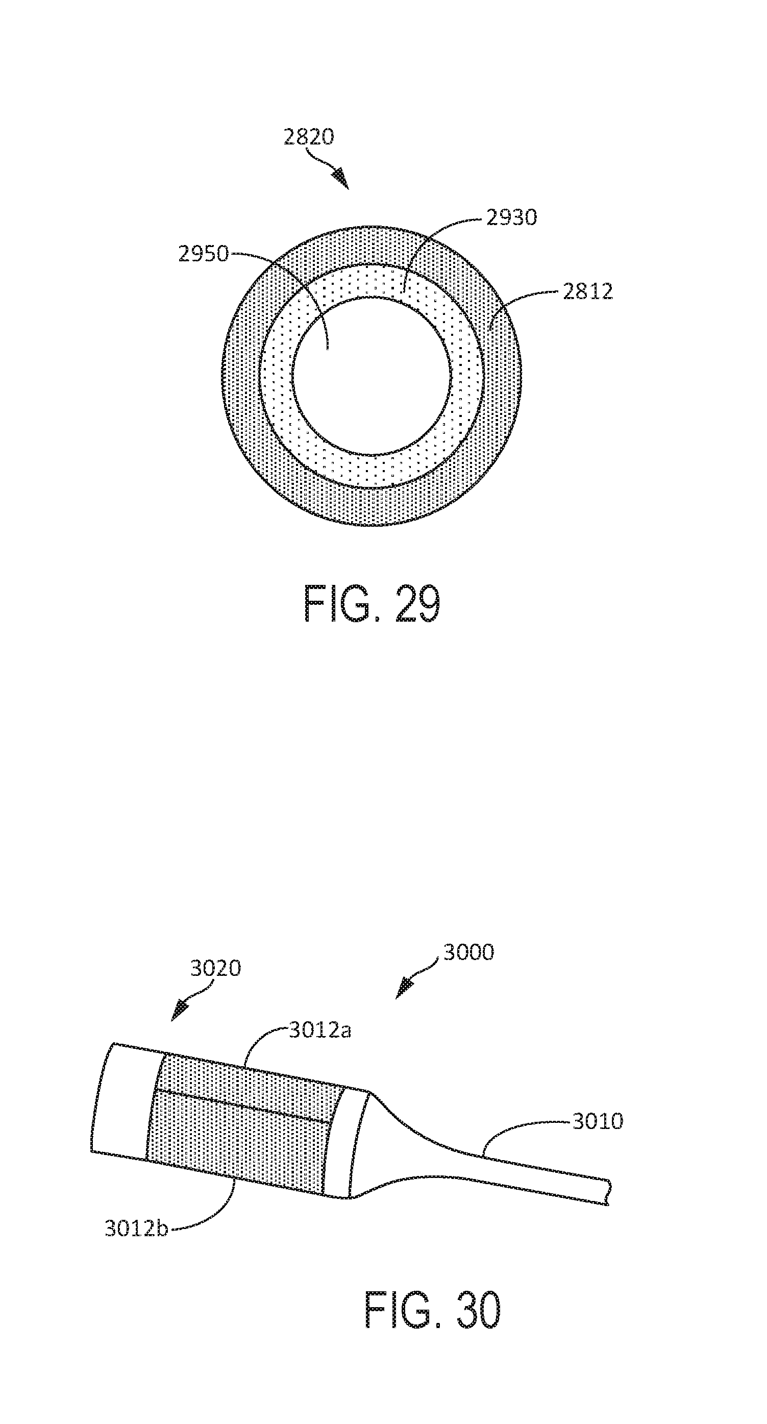
D00015

D00016

D00017

D00018

D00019

D00020

D00021

D00022

D00023

D00024

D00025
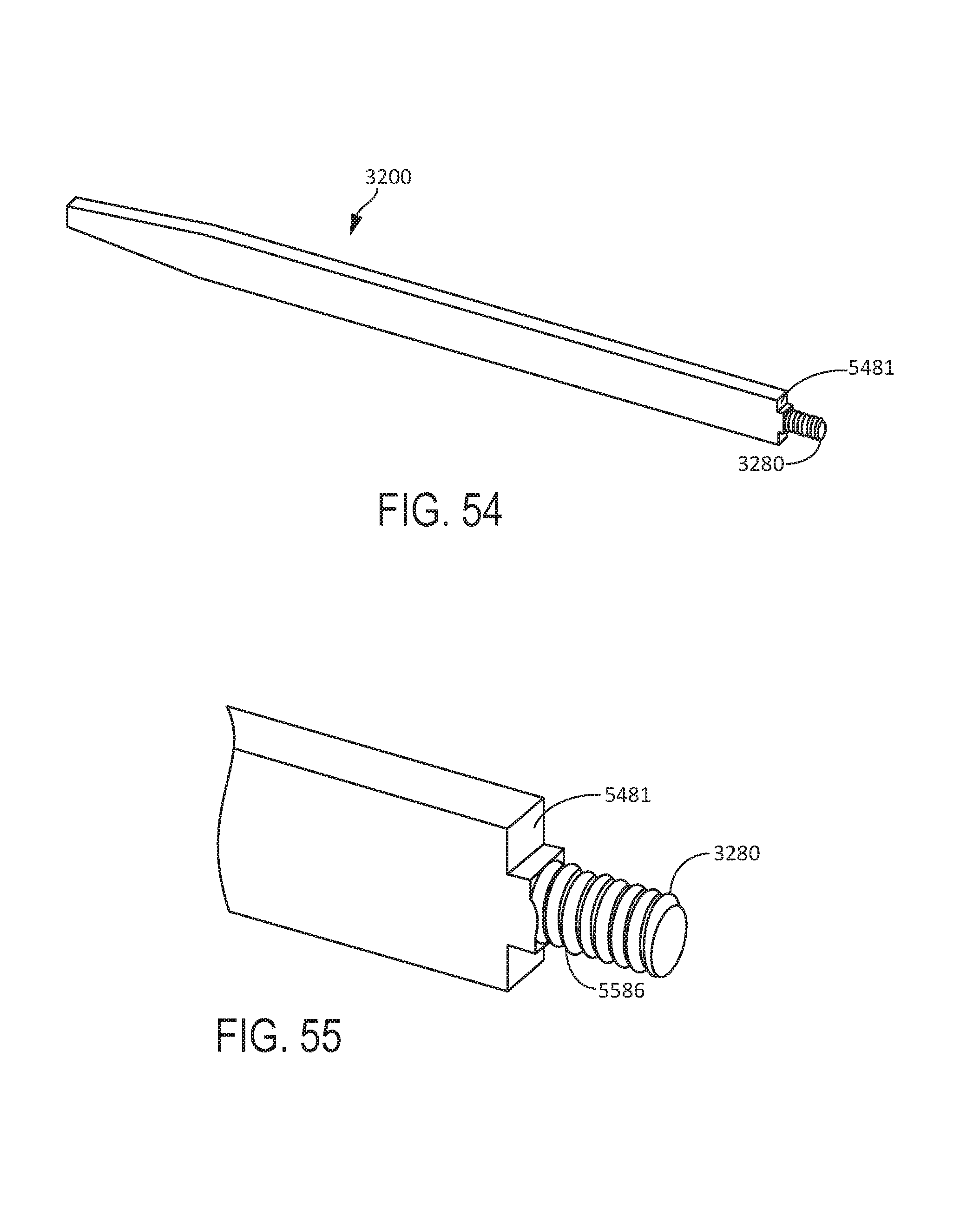
D00026

D00027

D00028

D00029

D00030

D00031

M00001

XML
uspto.report is an independent third-party trademark research tool that is not affiliated, endorsed, or sponsored by the United States Patent and Trademark Office (USPTO) or any other governmental organization. The information provided by uspto.report is based on publicly available data at the time of writing and is intended for informational purposes only.
While we strive to provide accurate and up-to-date information, we do not guarantee the accuracy, completeness, reliability, or suitability of the information displayed on this site. The use of this site is at your own risk. Any reliance you place on such information is therefore strictly at your own risk.
All official trademark data, including owner information, should be verified by visiting the official USPTO website at www.uspto.gov. This site is not intended to replace professional legal advice and should not be used as a substitute for consulting with a legal professional who is knowledgeable about trademark law.