Electric candle having flickering effect
Patton A
U.S. patent number 10,393,332 [Application Number 15/958,873] was granted by the patent office on 2019-08-27 for electric candle having flickering effect. This patent grant is currently assigned to L & L Candle Company, LLC. The grantee listed for this patent is L & L Candle Company, LLC. Invention is credited to Douglas Patton.


View All Diagrams
| United States Patent | 10,393,332 |
| Patton | August 27, 2019 |
Electric candle having flickering effect
Abstract
An electronic lighting device and a method for manufacturing the same are disclosed. A housing is formed for the light source support inside the housing. The light source support holds a light source that shines light onto a flame element. The flame element has an upper part shaped like a flame and a lower part extending in the opposite direction from the upper part allowing the flame element to move like a pendulum. The upper part can include a spherical ball that fits into a recess and the housing, and moves back and forth while being illuminated by the light source. In one embodiment, there is a circuit board in the housing, and the light source, as wealth an electromagnet to move the pendulum can both be mounted on the circuit board.
| Inventors: | Patton; Douglas (Irvine, CA) | ||||||||||
|---|---|---|---|---|---|---|---|---|---|---|---|
| Applicant: |
|
||||||||||
| Assignee: | L & L Candle Company, LLC
(Eden Prarie, MN) |
||||||||||
| Family ID: | 63854179 | ||||||||||
| Appl. No.: | 15/958,873 | ||||||||||
| Filed: | April 20, 2018 |
Prior Publication Data
| Document Identifier | Publication Date | |
|---|---|---|
| US 20180306396 A1 | Oct 25, 2018 | |
Related U.S. Patent Documents
| Application Number | Filing Date | Patent Number | Issue Date | ||
|---|---|---|---|---|---|
| 62487569 | Apr 20, 2017 | ||||
| Current U.S. Class: | 1/1 |
| Current CPC Class: | F21S 6/001 (20130101); F21S 10/046 (20130101); F21K 9/238 (20160801); F21K 9/235 (20160801); F21V 19/0055 (20130101); F21W 2121/00 (20130101); F21Y 2115/10 (20160801) |
| Current International Class: | F21S 10/04 (20060101); F21S 6/00 (20060101); F21K 9/235 (20160101); F21V 19/00 (20060101); F21K 9/238 (20160101) |
References Cited [Referenced By]
U.S. Patent Documents
| 782156 | February 1905 | Meeker |
| 817772 | April 1906 | Helmer |
| 1507371 | August 1924 | Goodridge |
| 1842167 | January 1932 | Hall |
| 1955042 | April 1934 | Work |
| D102561 | December 1936 | Lamb |
| 2435811 | February 1948 | Waters |
| 2932351 | June 1958 | Bried |
| 2976450 | March 1961 | Benoliel |
| 2984032 | May 1961 | Cornell |
| 3166863 | January 1965 | Gray |
| 3233093 | February 1966 | Gerlat |
| 3373274 | March 1968 | Kott |
| 3384774 | May 1968 | English |
| 3425157 | February 1969 | Hartsock |
| 3479561 | November 1969 | Janning |
| 3514660 | May 1970 | Kopelman |
| 3603013 | September 1971 | Gardiner |
| 3639749 | February 1972 | Beckman |
| 3681588 | August 1972 | Lee |
| 3814973 | June 1974 | Thouret et al. |
| 3890085 | June 1975 | Andeweg |
| 4026544 | May 1977 | Plambeck et al. |
| 4067111 | January 1978 | Truitt |
| 4187532 | February 1980 | Naffier |
| 4328534 | May 1982 | Abe |
| 4477249 | October 1984 | Ruzek et al. |
| 4550363 | October 1985 | Sandell |
| 4551794 | November 1985 | Sandell |
| 4617614 | October 1986 | Lederer |
| 4728871 | March 1988 | Andrews |
| 4764853 | August 1988 | Thomas |
| 4777571 | October 1988 | Morgan |
| 4866580 | September 1989 | Blackerby |
| 4965707 | October 1990 | Butterfield |
| 5072208 | December 1991 | Christensen |
| 5097180 | March 1992 | Ignon et al. |
| 5152602 | October 1992 | Boschetto |
| 5381325 | January 1995 | Messana |
| 5550452 | August 1996 | Shirai |
| 5582478 | December 1996 | Ambrosino |
| 5707282 | January 1998 | Clements et al. |
| 5924784 | July 1999 | Chliwnyj et al. |
| 5936521 | August 1999 | Blackman |
| 6198229 | March 2001 | McCloud |
| 6241362 | June 2001 | Morrison |
| 6257755 | July 2001 | Sevelle |
| 6302555 | October 2001 | Bristow |
| 6312137 | November 2001 | Hsieh |
| 6454425 | September 2002 | Lin |
| 6461011 | October 2002 | Harrison |
| 6491516 | December 2002 | Tal et al. |
| 6511219 | January 2003 | Sevelle |
| D486924 | February 2004 | Skradski et al. |
| 6688752 | February 2004 | Moore |
| 6712493 | March 2004 | Tell et al. |
| 6757487 | June 2004 | Martin et al. |
| 6781270 | August 2004 | Long |
| 6953401 | October 2005 | Starr |
| 6955440 | October 2005 | Niskanen |
| 6966665 | November 2005 | Limburg et al. |
| 7029146 | April 2006 | Kitchen |
| 7066637 | June 2006 | Nozawa et al. |
| 7080472 | July 2006 | Schroeter et al. |
| 7083315 | August 2006 | Hansler et al. |
| 7093949 | August 2006 | Hart et al. |
| 7111421 | September 2006 | Corry et al. |
| 7118243 | October 2006 | McCavit et al. |
| 7125142 | October 2006 | Wainwright |
| 7159994 | January 2007 | Schnuckle et al. |
| D545458 | June 2007 | Jensen |
| 7261455 | August 2007 | Schnuckle et al. |
| 7300179 | November 2007 | LaDuke et al. |
| 7305783 | December 2007 | Mix et al. |
| D567993 | April 2008 | Shiu |
| 7350720 | April 2008 | Jaworski et al. |
| 7360935 | April 2008 | Jensen et al. |
| 7410269 | August 2008 | Harrity |
| D576317 | September 2008 | Jensen |
| 7481571 | January 2009 | Bistritzky et al. |
| D589176 | March 2009 | Huang et al. |
| 7503668 | March 2009 | Porchia et al. |
| D599491 | September 2009 | Luo |
| 7633232 | December 2009 | Wong |
| 7686471 | March 2010 | Reichow |
| RE41628 | September 2010 | Barbeau |
| 7824627 | November 2010 | Michaels et al. |
| 7828462 | November 2010 | Jensen et al. |
| 7837355 | November 2010 | Schnuckle |
| 8070319 | December 2011 | Schnuckle et al. |
| 8081872 | December 2011 | Wang |
| 8132936 | March 2012 | Patton et al. |
| 8210708 | July 2012 | Hau et al. |
| 8235558 | August 2012 | Lauer |
| 8256935 | September 2012 | Cullimore et al. |
| 8342712 | January 2013 | Patton et al. |
| 8454190 | June 2013 | Negron |
| 8534869 | September 2013 | Patton et al. |
| 8550660 | October 2013 | Patton et al. |
| 8646946 | February 2014 | Schnuckle et al. |
| 8696166 | April 2014 | Patton et al. |
| 8721118 | May 2014 | Patton |
| 8727569 | May 2014 | Schnuckle et al. |
| 8789986 | July 2014 | Li |
| 8894261 | November 2014 | Chen |
| 8926137 | January 2015 | Li |
| 8998461 | April 2015 | Gutstein et al. |
| 9033553 | May 2015 | Li |
| 9052078 | June 2015 | Sheng |
| D740460 | October 2015 | Thompson et al. |
| D743096 | November 2015 | Patton et al. |
| D748322 | January 2016 | Patton et al. |
| D748843 | February 2016 | Thompson et al. |
| D752276 | March 2016 | Thompson et al. |
| 9322523 | April 2016 | Patton et al. |
| 9335014 | May 2016 | Li |
| 9360181 | June 2016 | Li |
| 9366402 | June 2016 | Li |
| 9371972 | June 2016 | Li |
| 9371973 | June 2016 | Li |
| 9541247 | January 2017 | Patton |
| D779707 | February 2017 | Thompson et al. |
| 9572236 | February 2017 | Patton |
| D781488 | March 2017 | Patton |
| 9585980 | March 2017 | Li |
| 9591729 | March 2017 | Patton |
| 9605824 | March 2017 | Li |
| 9625112 | April 2017 | Li |
| 9810388 | November 2017 | Li |
| 2001/0033488 | October 2001 | Chliwnyj et al. |
| 2002/0080601 | June 2002 | Meltzer |
| 2003/0041491 | March 2003 | Mix |
| 2003/0053305 | March 2003 | Lin |
| 2003/0072154 | April 2003 | Moore |
| 2004/0114351 | June 2004 | Stokes et al. |
| 2004/0165374 | August 2004 | Robinson |
| 2004/0223326 | November 2004 | Wainwright |
| 2005/0007779 | January 2005 | Nozawa |
| 2005/0097792 | May 2005 | Naden |
| 2005/0169666 | August 2005 | Porchia et al. |
| 2005/0169812 | August 2005 | Helf |
| 2005/0196716 | September 2005 | Haab |
| 2005/0225984 | October 2005 | Theobald |
| 2005/0254248 | November 2005 | Lederer |
| 2005/0285538 | December 2005 | Jaworski et al. |
| 2006/0034079 | February 2006 | Schnuckle et al. |
| 2006/0034100 | February 2006 | Schnuckle et al. |
| 2006/0039835 | February 2006 | Nottingham et al. |
| 2006/0101681 | May 2006 | Hess et al. |
| 2006/0120080 | June 2006 | Sipinski et al. |
| 2006/0125420 | June 2006 | Boone |
| 2006/0146544 | July 2006 | Leung |
| 2006/0192503 | August 2006 | Trombetta et al. |
| 2007/0002560 | January 2007 | Gutstein et al. |
| 2007/0053174 | March 2007 | Lin |
| 2007/0127249 | June 2007 | Medley et al. |
| 2007/0154857 | July 2007 | Cho |
| 2007/0159422 | July 2007 | Blandino et al. |
| 2007/0223217 | September 2007 | Hsu |
| 2007/0236947 | October 2007 | Jensen et al. |
| 2008/0031784 | February 2008 | Bistritzky et al. |
| 2008/0038156 | February 2008 | Jaramillo |
| 2008/0074875 | March 2008 | Jensen et al. |
| 2008/0112154 | May 2008 | Reichow |
| 2008/0129226 | June 2008 | DeWitt et al. |
| 2008/0130266 | June 2008 | DeWitt et al. |
| 2008/0150453 | June 2008 | Medley et al. |
| 2008/0151563 | June 2008 | Chen |
| 2008/0151571 | June 2008 | Tang |
| 2009/0059596 | March 2009 | Lederer |
| 2009/0135586 | May 2009 | Yang |
| 2010/0001662 | January 2010 | Nelkin |
| 2010/0001682 | January 2010 | Dickson et al. |
| 2010/0079999 | April 2010 | Schnuckle |
| 2010/0134022 | June 2010 | Gutstein et al. |
| 2010/0207538 | August 2010 | Chen |
| 2011/0000666 | January 2011 | Couto |
| 2011/0019422 | January 2011 | Schnuckle |
| 2011/0027124 | February 2011 | Albee et al. |
| 2011/0110073 | May 2011 | Schnuckle et al. |
| 2011/0127914 | June 2011 | Patton |
| 2011/0134628 | June 2011 | Pestl et al. |
| 2011/0195787 | August 2011 | Wells |
| 2011/0204828 | August 2011 | Moody et al. |
| 2011/0317403 | December 2011 | Fournier et al. |
| 2012/0020052 | January 2012 | McCavit et al. |
| 2012/0024837 | February 2012 | Thompson |
| 2012/0049765 | March 2012 | Lu |
| 2012/0093491 | April 2012 | Browder et al. |
| 2012/0134157 | May 2012 | Li |
| 2013/0050985 | February 2013 | Kwok et al. |
| 2013/0163249 | June 2013 | Miura |
| 2013/0223043 | August 2013 | Ray |
| 2013/0265748 | October 2013 | Negron |
| 2014/0035483 | February 2014 | Becker |
| 2014/0140042 | May 2014 | Schreiber |
| 2014/0211458 | July 2014 | Lai |
| 2014/0211499 | July 2014 | Fong |
| 2014/0218903 | August 2014 | Sheng |
| 2014/0241004 | August 2014 | Chen |
| 2014/0254148 | September 2014 | Fournier |
| 2014/0268652 | September 2014 | Li |
| 2014/0268704 | September 2014 | Yang |
| 2014/0274212 | September 2014 | Zurek et al. |
| 2014/0286024 | September 2014 | Li |
| 2014/0313694 | October 2014 | Patton |
| 2014/0362592 | December 2014 | Lee |
| 2015/0008845 | January 2015 | Kim |
| 2015/0036348 | February 2015 | Dong |
| 2015/0070874 | March 2015 | Beesley |
| 2015/0109786 | April 2015 | Li |
| 2015/0124442 | May 2015 | Ding |
| 2015/0233538 | August 2015 | Sheng |
| 2015/0292698 | October 2015 | Li |
| 2015/0308643 | October 2015 | Huang |
| 2015/0369431 | December 2015 | Li |
| 2015/0369432 | December 2015 | Li |
| 2015/0373815 | December 2015 | Patton |
| 2016/0040844 | February 2016 | Patton |
| 2016/0047517 | February 2016 | Li |
| 2016/0057829 | February 2016 | Li |
| 2016/0109082 | April 2016 | Li |
| 2016/0109083 | April 2016 | Li |
| 2016/0163630 | June 2016 | Kummerl |
| 2016/0186947 | June 2016 | Li |
| 2016/0258584 | September 2016 | Li |
| 2016/0290580 | October 2016 | Li |
| 2016/0298816 | October 2016 | Fang |
| 2017/0067606 | March 2017 | Li |
| 2017/0211767 | July 2017 | Baeza |
| 2017/0307159 | October 2017 | Li |
| 2017/0367163 | December 2017 | Li |
| 1030823 | Feb 1989 | CN | |||
| 2483103 | Mar 2002 | CN | |||
| 2551859 | May 2003 | CN | |||
| 2562059 | Jul 2003 | CN | |||
| 1530142 | Sep 2004 | CN | |||
| 1646177 | Jul 2005 | CN | |||
| 2854329 | Jan 2007 | CN | |||
| 2888274 | Apr 2007 | CN | |||
| 2924266 | Jul 2007 | CN | |||
| 200940808 | Aug 2007 | CN | |||
| 201011621 | Jan 2008 | CN | |||
| 201059432 | May 2008 | CN | |||
| 201093300 | Jul 2008 | CN | |||
| 201103952 | Aug 2008 | CN | |||
| 201159425 | Dec 2008 | CN | |||
| 101408284 | Apr 2009 | CN | |||
| 201235095 | May 2009 | CN | |||
| 201418887 | Mar 2010 | CN | |||
| 201533921 | Jul 2010 | CN | |||
| 101865413 | Oct 2010 | CN | |||
| 201643048 | Nov 2010 | CN | |||
| 102147095 | Aug 2011 | CN | |||
| 102563510 | Jul 2012 | CN | |||
| 102734740 | Oct 2012 | CN | |||
| 102748589 | Oct 2012 | CN | |||
| 202708962 | Jan 2013 | CN | |||
| 202791780 | Mar 2013 | CN | |||
| 203131550 | Aug 2013 | CN | |||
| 103322500 | Sep 2013 | CN | |||
| 20329818 | Nov 2013 | CN | |||
| 203273669 | Nov 2013 | CN | |||
| 203273670 | Nov 2013 | CN | |||
| 203431703 | Feb 2014 | CN | |||
| 203442498 | Feb 2014 | CN | |||
| 203517611 | Apr 2014 | CN | |||
| 203571618 | Apr 2014 | CN | |||
| 104048246 | Sep 2014 | CN | |||
| 104089241 | Oct 2014 | CN | |||
| 203940346 | Nov 2014 | CN | |||
| 204268356 | Apr 2015 | CN | |||
| 1489617 | May 1969 | DE | |||
| 212011100014 | Apr 2012 | DE | |||
| 102012206988 | Oct 2013 | DE | |||
| 202014100821 | Apr 2014 | DE | |||
| 202013012047 | Apr 2015 | DE | |||
| 202015000490 | Apr 2015 | DE | |||
| 202015102274 | Jun 2015 | DE | |||
| 0138786 | Apr 1985 | EP | |||
| 0855189 | Jul 1998 | EP | |||
| 1639291 | Mar 2006 | EP | |||
| 1838110 | Sep 2007 | EP | |||
| 2587127 | May 2013 | EP | |||
| 499745 | Jan 1939 | GB | |||
| 2230335 | Oct 1990 | GB | |||
| 2267746 | Dec 1993 | GB | |||
| 2323159 | Sep 1998 | GB | |||
| 2379731 | Mar 2003 | GB | |||
| 2385413 | Aug 2003 | GB | |||
| 2443926 | May 2008 | GB | |||
| 2455598 | Jun 2009 | GB | |||
| 2527626 | Dec 2015 | GB | |||
| H0652709 | Feb 1994 | JP | |||
| H1057464 | Mar 1998 | JP | |||
| 2000284730 | Oct 2000 | JP | |||
| 2008180755 | Aug 2008 | JP | |||
| 101174246 | Aug 2012 | KR | |||
| WO-1982002756 | Aug 1982 | WO | |||
| WO-1985003561 | Aug 1985 | WO | |||
| WO-1987004506 | Jul 1987 | WO | |||
| WO-1996025624 | Aug 1996 | WO | |||
| WO-2001092780 | Dec 2001 | WO | |||
| WO-2003011349 | Feb 2003 | WO | |||
| WO-2006020839 | Feb 2006 | WO | |||
| WO2007002560 | Jan 2007 | WO | |||
| WO-2008092753 | Aug 2008 | WO | |||
| WO-2010009575 | Jan 2010 | WO | |||
| WO-2012000418 | Jan 2012 | WO | |||
| WO2012099718 | Jul 2012 | WO | |||
| WO2012162538 | Nov 2012 | WO | |||
| WO-2013020263 | Feb 2013 | WO | |||
| WO2013020439 | Feb 2013 | WO | |||
| WO2014139483 | Sep 2014 | WO | |||
| WO2016000517 | Jan 2016 | WO | |||
Other References
|
US. Appl. No. 15/411,869, filed Jan. 20, 2017, Li. cited by applicant . U.S. Appl. No. 15/413,305, filed Jan. 23, 2017, Li. cited by applicant . U.S. Appl. No. 15/150,057, filed May 9, 2016, Li. cited by applicant . U.S. Appl. No. 15/322,237, filed Nov. 18, 2014, Li. cited by applicant . U.S. Appl. No. 15/418,451, filed Jan. 27, 2017, Li. cited by applicant . U.S. Appl. No. 15/441,143, filed Feb. 23, 2017, Li. cited by applicant . U.S. Appl. No. 15/451,351, filed Mar. 6, 2017, Li. cited by applicant . U.S. Appl. No. 15/368,168, filed Dec. 2, 2016, Li. cited by applicant . U.S. Appl. No. 15/451,361, filed Mar. 6, 2017, Li. cited by applicant . Non-Final Office Action for U.S. Appl. No. 15/197,354, dated Jan. 19, 2017, 36 pages. cited by applicant . Notice of Allowance for U.S. Appl. No. 15/137,951 dated Feb. 28, 2017, 10 pages. cited by applicant . Non-Final Office Action for U.S. Appl. No. 15/368,168, dated Mar. 13, 2017, 36 pages. cited by applicant . Translated Office Action issued by the German patent and Trade Mark Office dated Mar. 16, 2017 for Application No. 102016008825.7, 8 pages. cited by applicant . Non-Final Office Action for U.S. Appl. No. 15/355,408, dated Feb. 8, 2017, 26 pages. cited by applicant . Notice of Allowance for U.S. Appl. No. 14/672,819, dated Jan. 27, 2017, 14 pages. cited by applicant . Translated Office Action issued by the German patent and Trade Mark Office dated Feb. 16, 2017 for Application No. 102016008226.7, 6 pages. cited by applicant . Translated Office Action issued by the German patent and Trade Mark Office dated Mar. 2, 2017 for Application No. 102016009125.8, 5 pages. cited by applicant . MiPow Playbulb Candle, Android, http://www.mipow.de/smart-home/29/mipow-playbulb-candle, archived on http://www.archive.org on May 14, 2016 [accessed Mar. 2, 2017]. cited by applicant . CHIP: Progimax Candle, http://beste-apss.chip.de/android/app/kostenloses-candle-kerzen-app-fuer-- den-androiden.com.progimax.candle.free/ , archived on http://www.archive.org on Dec. 30, 2013 [accessed on Mar. 2, 2017]. cited by applicant . Notice of Allowance for U.S. Appl. No. 15/158,508 dated Sep. 21, 2016, 8 pages. cited by applicant . Notice of Allowance for U.S. Appl. No. 15/061,648, dated Sep. 23, 2016, 9 pages. cited by applicant . Non-Final Office Action for U.S. Appl. No. 15/137,951, dated Oct. 24, 2016, 28 pages. cited by applicant . UK Combined Search and Examination Report for GB1613387.8, dated Sep. 9, 2016, 10 pages. cited by applicant . UK Combined Search and Examination Report for GB1613393.6, dated Sep. 9, 2016, 10 pages. cited by applicant . Canadian Examination and Search Report for CA2936224, dated Sep. 30, 2016, 5 pages. cited by applicant . UK Combined Search and Examination Report for GB1613391.0, dated Sep. 19, 2016, 9 pages. cited by applicant . Notice of Allowance for U.S. Appl. No. 14/449,865 dated Nov. 16, 2016, 15 pages. cited by applicant . Notice of Allowance for U.S. Appl. No. 15/145,739 dated Nov. 17, 2016, 11 pages. cited by applicant . Notice of Allowance for U.S. Appl. No. 15/187,618 dated Nov. 30, 2016, 12 pages. cited by applicant . Canadian Examination and Search Report for CA2936225, dated Sep. 29, 2016, 5 pages. cited by applicant . Non-Final Office Action for U.S. Appl. No. 15/371,103, dated Jan. 25, 2017, 45 pages. cited by applicant . Notice of Allowance for Canadian Patent Application No. 2,930,065, dated Feb. 9, 2017 from the Canadian Intellectual Property Office. cited by applicant . Canadian Examination Report for CA2930099, dated Jan. 5, 2017 from the Canadian Intellectual Property Office, 3 pages. cited by applicant . Translated Office Action issued by the German patent and Trade Mark Office dated Dec. 19, 2016 for Application No. 102016008225.9, 5 pages. cited by applicant . Notice of Allowance for U.S. Appl. No. 15/207,411 dated Jan. 20, 2017, 23 pages. cited by applicant . Notice of Allowance for Canadian Patent Application No. 2,936,225, dated Jan. 16, 2017 from the Canadian Intellectual Property Office. cited by applicant . Notice of Allowance for U.S. Appl. No. 15/371,103 dated Apr. 12, 2017, 10 pages. cited by applicant . U.S. Appl. No. 15/132,548, filed Apr. 19, 2016, Li. cited by applicant . U.S. Appl. No. 15/145,739, filed May 3, 2016, Li. cited by applicant . U.S. Appl. No. 15/197,354, filed Jun. 29, 2016, Li. cited by applicant . U.S. Appl. No. 15/137,951, filed Apr. 25, 2016, Li. cited by applicant . U.S. Appl. No. 61/101,611 to Schnuckle, filed Sep. 30, 2008. cited by applicant . U.S. Appl. No. 61/293,516 to Patton, filed Jan. 8, 2010. cited by applicant . International Search Report and Written Opinion for PCT Application No. PCT/CN/2014/073557 dated Jul. 2, 2014. cited by applicant . International Search Report for PCT Application No. PCT/US2009/054401 dated Oct. 26, 2009. cited by applicant . EP Search Report for European Patent Application No. 12185984.7 dated Dec. 14, 2012. cited by applicant . Engineer's Handbook (Epoxy definition), http://engineershandbook.com/Materials/epoxy.htm, Jul. 18, 2013. cited by applicant . Nagashima, H. et al., "Introduction to Chaos, Physics and Mathematics of Chaotic Phenomena," Institute of Physics Publishing, 1999. cited by applicant . Definition of "Electromagnet" in the Encarta World English Dictionary, Aug. 1999. cited by applicant . Lab M3: The Physical Pendulum, Physics 1140--Experimental Physics, Course Laboratory Instructions, 2000. cited by applicant . Non-Final Office Action for U.S. Appl. No. 12/273,337 dated Jun. 17, 2011, 16 pages. cited by applicant . Notice of Allowance for U.S. Appl. No. 12/273,337 dated Mar. 26, 2012, 8 pages. cited by applicant . Final Office Action for U.S. Appl. No. 12/273,337 dated Jan. 18, 2012, 17 pages. cited by applicant . Non-Final Office Action for U.S. Appl. No. 13/526,067 dated Oct. 22, 2012, 23 pages. cited by applicant . Notice of Allowance for U.S. Appl. No. 13/526,067 dated Feb. 6, 2013, 8 pages. cited by applicant . Non-Final Office Action for U.S. Appl. No. 13/908,571 dated Sep. 6, 2013, 11 pages. cited by applicant . Final Office Action for U.S. Appl. No. 13/908,571 dated Mar. 18, 2014, 20 pages. cited by applicant . Final Office Action for U.S. Appl. No. 13/098,571 dated Sep. 30, 2014, 18 pages. cited by applicant . Notice of Allowance for U.S. Appl. No. 13/325,754 dated Jun. 18, 2014, 10 pages. cited by applicant . Non-Final Office Action for U.S. Appl. No. 13/325,754 dated Dec. 30, 2013, 14 pages. cited by applicant . Notice of Allowance for U.S. Appl. No. 14/161,143, dated Nov. 13, 2014, 18 pages. cited by applicant . Non-Final Office Action for U.S. Appl. No. 14/558,507 dated Sep. 20, 2015, 21 pages. cited by applicant . Notice of Allowance for U.S. Appl. No. 14/588,507 dated Dec. 4, 2015, 11 pages. cited by applicant . Non-Final Office Action for U.S. Appl. No. 14/558,507 dated Mar. 17, 2016, 18 pages. cited by applicant . Notice of Allowance for U.S. Appl. No. 14/588,507 dated May 3, 2016, 7 pages. cited by applicant . Non-Final Office Action for U.S. Appl. No. 14/925,893 dated Feb. 25, 2016, 37 pages. cited by applicant . Final Office Action for U.S. Appl. No. 14/925,893, dated Apr. 26, 2016, 29 pages. cited by applicant . Non-Final Office Action for U.S. Appl. No. 14/925,893 dated May 16, 2016, 13 pages. cited by applicant . Non-Final Office Action for U.S. Appl. No. 14/925,899 dated Jan. 5, 2016, 21 pages. cited by applicant . Non-Final Office Action for U.S. Appl. No. 14/925,899 dated Apr. 14, 2016, 25 pages. cited by applicant . Non-Final Office Action for U.S. Appl. No. 14/927,213 dated Feb. 25, 2016, 33 pages. cited by applicant . Notice of Allowance for U.S. Appl. No. 14/927,213 dated May 11, 2016, 12 pages. cited by applicant . Non-Final Office Action for U.S. Appl. No. 14/925,899 dated May 25, 2016, 18 pages. cited by applicant . Supplementary Search Report and Opinion for EP 14764844, dated Jul. 28, 2016, 12 pages. cited by applicant . Non-Final Office Action for U.S. Appl. No. 15/145,739 dated Jul. 27, 2016, 22 pages. cited by applicant . Notice of Allowance for U.S. Appl. No. 14/925,893, dated Jul. 20, 2016, 9 pages. cited by applicant . Notice of Allowance for U.S. Appl. No. 14/925,899, dated Aug. 3, 2016, 9 pages. cited by applicant . Non-Final Office Action for U.S. Appl. No. 15/061,648 dated Jul. 12, 2016, 47 pages. cited by applicant . Non-Final Office Action for U.S. Appl. No. 14/449,865 dated Feb. 3, 2016, 9 pages. cited by applicant . International Search Report for PCT/CN2014/091362, dated Apr. 3, 2015, 2 pages. cited by applicant . Non-Final Office Action for U.S. Appl. No. 15/187,618, dated Aug. 18, 2016, 13 pages. cited by applicant. |
Primary Examiner: Ton; Anabel
Attorney, Agent or Firm: Law Office of Scott C Harris, Inc
Parent Case Text
CROSS REFERENCE TO RELATED APPLICATIONS
The present application claims priority from provisional application No. 62/487,569, filed Apr. 20, 2017, the entire disclosure of which is hereby incorporated by reference in its entirety.
Claims
What is claimed is:
1. An electric lighting device, comprising: a circuit board, having electronic circuitry thereon; a support coupled to the circuit board; a light source support coupled to the circuit board and configured to receive and support a light source; a housing comprising an internal cavity, wherein the housing is configured to couple to the supports and to hold the supports; and a flame element coupled to the housing such that the flame element is movable with respect to the housing and where the light source support faces towards the flame element further comprising an electromagnet located on the light source, the electromagnet interacting with the flame element, and causing the flame element to move.
2. The electric lighting device as in claim 1, wherein further comprising at least one circuit on the circuit board which controls energization of the electromagnet to move the flame element.
3. The electric lighting device as in claim 2, further comprising an arm connected to the flame element, the arm extending inside the housing, and wherein said arm includes a magnetic element at a distal portion thereof and where the electromagnet in the housing causes pendulum like movement of the flame element.
4. An electric lighting device, comprising: a flame member operating to move like a pendulum, having a upper portion having a flame-shaped appearance, and a spherical body portion disposed beneath the upper portion; and a housing comprising a socket configured to receive the spherical body portion, and to allow the spherical body portion to move within the socket, wherein the flame member also includes an arm extending from the spherical body portion in it opposite direction from the flame member; and an arm moving device, in the housing, causing the arm to move and thereby causing the flame member to move.
5. The electric lighting device as in claim 4, further comprising a light source, coupled to said housing, and directing light onto a surface of the flame member.
6. The electric lighting device as in claim 5, further comprising a circuit board, mounted in the housing, wherein the light source is on a holder, and where the holder is connected to the circuit board.
7. The device of claim 4 wherein the arm comprises a first wing configured to restrict movement of the arm of the flame member.
8. The device as in claim 4, wherein a portion on the arm includes a magnet, and further comprising an electromagnet which interacts with the arm to move the flame portion.
9. The device as in claim 6, wherein a portion on the arm includes a magnet, and further comprising an electromagnet, mounted on the circuit board, which interacts with the arm to move the flame portion.
Description
TECHNICAL FIELD
The field of the invention is electronic lighting devices, and in particular, electric candles.
BACKGROUND
The background description includes information that may be useful in understanding the present invention. It is not an admission that any of the information provided herein is prior art or relevant to the presently claimed invention, or that any publication specifically or implicitly referenced qualifies as prior art under the law.
Various electric lights are known in the art. See, e.g., U.S. Pat. No. 8,132,936 to Patton et al., U.S. Pat. No. 8,070,319 to Schnuckle et al., U.S. Pat. No. 7,837,355 to Schnuckle et al., U.S. Pat. No. 7,261,455 to Schnuckle et al., U.S. Pat. No. 7,159,994 to Schnuckle et al., US 2011/0127914 to Patton et al., U.S. Pat. No. 7,350,720 to Jaworski et al.; US 2005/0285538 to Jaworski et al. (publ. December 2005); U.S. Pat. No. 7,481,571 to Bistritzky et al.; US 2008/0031784 to Bistritzky et al. (publ. February 2008); US 2006/0125420 to Boone et al. (publ. June 2006); US 2007/0127249 to Medley et al. (publ. June 2007); US 2008/0150453 to Medley et al. (publ. June 2008); US 2005/0169666 to Porchia, et al. (publ. August 2005); U.S. Pat. No. 7,503,668 to Porchia, et al.; U.S. Pat. No. 7,824,627 to Michaels, et al.; US 2006/0039835 to Nottingham et al. (publ. February 2006); US 2008/0038156 to Jaramillo (publ. February 2008); US 2008/0130266 to DeWitt et al. (publ. June 2008); US 2012/0024837 to Thompson (publ. February 2012); US 2011/0134628 to Pestl et al. (publ. June 2011); US 2011/0027124 to Albee et al. (publ. February 2011); US 2012/0020052 to McCavit et al. (publ. January 2012); US 2012/0093491 to Browder et al. (publ. April 2012); and US 2014/0218903 to Sheng.
However, there is still a need in the art for improved electric candles and other lighting devices that generate a flickering flame effect.
SUMMARY OF THE INVENTION
The present invention provides apparatus, systems, and methods in which an electronic lighting device (e.g., an artificial candle) comprises a structure that helps to simulate a real candle flame, preferably in the look of a traditional candle.
One should appreciate that the disclosed subject matter provides many advantageous technical effects including providing various designs of an artificial candle that simulate a real candle light. Thus, many drawbacks of conventional methods of providing an artificial candle can be reduced, and even possibly eliminated, by the disclosed subject matter.
Various objects, features, aspects and advantages of the inventive subject matter will become more apparent from the following detailed description of preferred embodiments, along with the accompanying drawing figures in which like numerals represent like components.
BRIEF DESCRIPTION OF THE DRAWINGS
FIGS. 1A-1D are perspective, top, vertical cross-section, and exploded views, respectively, of one embodiment of an electronic lighting device.
FIGS. 2A-2B are top, perspective and bottom, perspective views, respectively of an embodiment of an outer shell of the electronic lighting device shown in FIG. 1A.
FIGS. 3A-3B are top, perspective and bottom, perspective views, respectively of an embodiment of an inner shell of the electronic lighting device shown in FIG. 1A.
FIGS. 4A-4D are top perspective, bottom perspective, first vertical and second vertical cross-section views, respectively, of a housing of the electronic lighting device shown in FIG. 1A.
FIGS. 5A-5C are various exploded views of one embodiment of a pendulum member of the electronic lighting device shown in FIG. 1A.
FIG. 6 is a perspective view of one embodiment of a light source holder and a circuit board of the electronic lighting device shown in FIG. 1A
FIGS. 7A-7D are various cross-section views of a second embodiment of an electronic lighting device.
FIGS. 8A-8B are cross-section views of a third embodiment of an electronic lighting device.
FIG. 9 is a cross-section view of a fourth embodiment of an electronic lighting device.
DETAILED DESCRIPTION
The following discussion provides example embodiments of the inventive subject matter. Although each embodiment represents a single combination of inventive elements, the inventive subject matter is considered to include all possible combinations of the disclosed elements. Thus if one embodiment comprises elements A, B, and C, and a second embodiment comprises elements B and D, then the inventive subject matter is also considered to include other remaining combinations of A, B, C, or D, even if not explicitly disclosed.
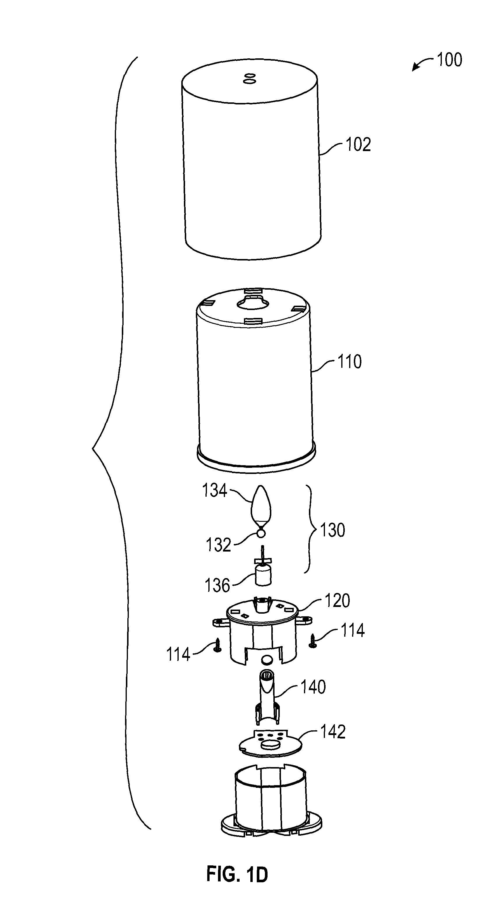
In FIGS. 1A-6, an embodiment of an electric lighting device 100 is shown that is shaped like a traditional, wax candle. The device 100 comprises an outer wax or wax-like shell 102 having an aperture 106 in the upper surface 104 through which light from a light source can be emitted. The upper surface can include a second aperture 108, and in other embodiments described below, could alternatively comprise a divot or recess into which the flame element is mounted. As shown best in FIG. 2B, the bottom of the upper surface preferably comprises a recessed area 109 near or adjacent to the one or more apertures, which can act as a guide to ensure proper installation of housing 130 into the recessed area 109. FIG. 1C shows how the housing 130 is held into the surfaces of that recessed area 109. Preferably, the outer shell 102 comprises a cylindrical shape, but could be differently shaped without departing from the scope of the invention. In one embodiment, the flame element can have a hollow interior.
The outer shell 102 is preferably injection molded using a wax or wax composite. Alternatively, the outer shell 102 could be formed via extrusion or other manners, some of which are described in co-pending application having Ser. No. 15/096,061 filed on Apr. 11, 2016.
The device 100 further comprises an inner shell 110 sized to be disposed within the outer shell 102. The inner shell 110 preferably comprises an injection-molded piece that includes one or more receptors 112 for fasteners. Advantageously, the housing 120 can thereby be secured to the inner shell 110 using fasteners such as screws 114 shown in FIG. 1D, which reduces the amount of internal structure required to support the components utilized to produce the flickering flame effect.
As an alternative embodiment, the inner and outer shells could comprise a single injection molded piece that includes the receptors. This advantageously reduces the overall cost of manufacture and simplifies the assembly process. Further discussion of these concepts can be found in co-pending patent application having Ser. No. 15/096,061 filed on Apr. 11, 2016.
The inner shell 110 can include one or more keyways 115 that can be used to ensure proper alignment of components disposed within the inner shell 110. The inner shell 110 can further include one more receptors 116 for fasteners, which allow for a base of the device 100 to be coupled with the inner shell 110.
A housing 120 can be disposed within the inner shell 110, and configured to support the flame element 130. An upper surface 122 of the housing 120 preferably is shaped to mate with the recessed area 109 of the outer shell 102.
The upper surface 122 preferably comprises a socket or cup 124 configured to receive and support a spherical body (ball) 132 of the flame element 130. The flame element can act as a pendulum member. This is best shown in FIGS. 4C and 4D. Once inserted, the ball 132 can move within the socket 124, which in turns move the flame-shaped portion 134 of the pendulum member 130. To limit movement of the flame element 130 within the housing 120, the housing 120 can include one or more projections 126 that restrict overall movement of the flame member 130 by preventing movement outside a defined area or region. In an alternative embodiment, flexible wires or other material could be used to act as a spring or bias to limit movement of the flame member 130 and supply a force to help return the pendulum member 130 to a steady state position.
It is contemplated that the spherical body 132 can comprise regions having a material with a lower coefficient of friction that the rest of the body 132 such that friction between the body 132 and socket 124 can be reduced. It is also contemplated that the body 132 can include raised portions or bumps that preferably comprise a different material to reduce friction between the body 132 and socket 124.
By using a ball/socket combination, the illusion of a flickering flame is further accented by eliminating a visible hole in the upper surface 104 of the outer shell 102 where the flame member is located and that found in many prior art devices, and concealing the structure that holds the flame member in place and provides for its movement.
The housing 120 can further include a cut-out 128 where a light source can be mounted separately from the housing 120, and preferably be inserted into place once the housing 120 is coupled to the inner shell 110. Housing 120 can also include receptors 129 that align with receptors 112 of the inner shell 110, such that the housing 120 can be coupled to the inner shell 110 using one or more screws 114 or other fasteners.
Flame element 130 preferably comprises upper and lower portions, with the upper portion 134 having a flame-shaped appearance connected to a spherically-shaped lower piece 132 by a thinner middle portion 131. It is contemplated that the middle portion 131 could have a dark color to thereby resemble a wick. The lower portion can include a projection 139 extending from a base 136, with the projection 139 sized and dimensioned to be inserted into the opening 133 of the ball or spherical region 132. It is contemplated that the projection 139 can be secured within the spherically-shaped lower piece 132 via a friction-fit, snap-fit, or be screwed into the lower piece 132, to thereby prevent unintentional disconnection of the upper and lower portions. The flame element 130 is partially housed within the housing 120, such that the flame element 130 is allowed to move in a manner that simulates a moving flame. A detailed description of embodiments of a flame element and housing can be found in co-pending application having Ser. No. 14/819,146.
Preferably, the base 136 of the flame member 130 is sized and dimensioned to be larger in diameter than a diameter of the aperture 121 in the housing 120. In this manner, when the base 136 is coupled to the upper portion, the upper portion is prevented from being removed from the device 100 because the base 136 cannot pass through the aperture 121. Base 136 can also be configured to receive a magnet in recess 137. In this manner, the magnet can interact with a magnetic field generated by an electromagnet, for example, to thereby cause movement of the flame member 130.
Flame member 130 can further include one or more wings 138, which in conjunction with projections 126 or other structure limits movement of the pendulum member 130 with respect to the housing 120.
Device 100 can further include a light source holder 140 that preferably attaches to a circuit board or circuit board cover 142 via support bracings 146 that protrude from the bottom end of the holder's column. The support bracings can be inserted into holes on the board or cover 142. The support bracings are configured to stabilize the column and light source against the circuit board such that the angle and position of the light source advantageously remains stationary once installed. In a preferred embodiment, it is contemplated that the holder 140 can be secured in place via a screw or other fastener(s) to prevent movement of the holder 140 once installed.
The light source holder 140 preferably includes four support bracings that are spread evenly around the column and protrude in different angles from the column. It is contemplated that the column could be attached with any material or mechanism suitable for stabilizing the holder, and it is further contemplated that there could be any number of support bracings. The support bracings preferably have flat bottoms that lay against the circuit board and each support bracing can have a small pin protrusion that can fit in an aperture in the circuit board to provide more stability. It is contemplated that the support bracings and column can be manufactured as a single piece via injection molding. By creating the support bracings and column as a single piece, the overall complexity of the device is significantly reduced. By forming the support bracings and column as a single piece, the number of parts is reduced, simplifying assembly (e.g., by robotic or human assembly lines).
The light source holder 140 preferably comprises a light source, a lens, a column, and support bracings. The column has a bottom end and an angled top end. The angled top end is configured to receive the light source and the lens, and preferably includes a recess 144 to receive and support a lens to direct light from a LED or other light source against the flame-shaped piece 134 of the flame member 130. The angle of the angled end is configured with respect to the flame element 130 to precisely create the effect of a real candle. It is contemplated that the column could be of any shape (e.g., cylindrical, rectangular, etc.). Further discussion concerning the light source holder can be found in application having Ser. No. 62/267,168 filed on Dec. 14, 2015.
Circuit board 142 can control a drive mechanism, which could be an electromagnet, a fan, or other component that creates kinetic motion on the flame element to simulate the movement of a moving flame.
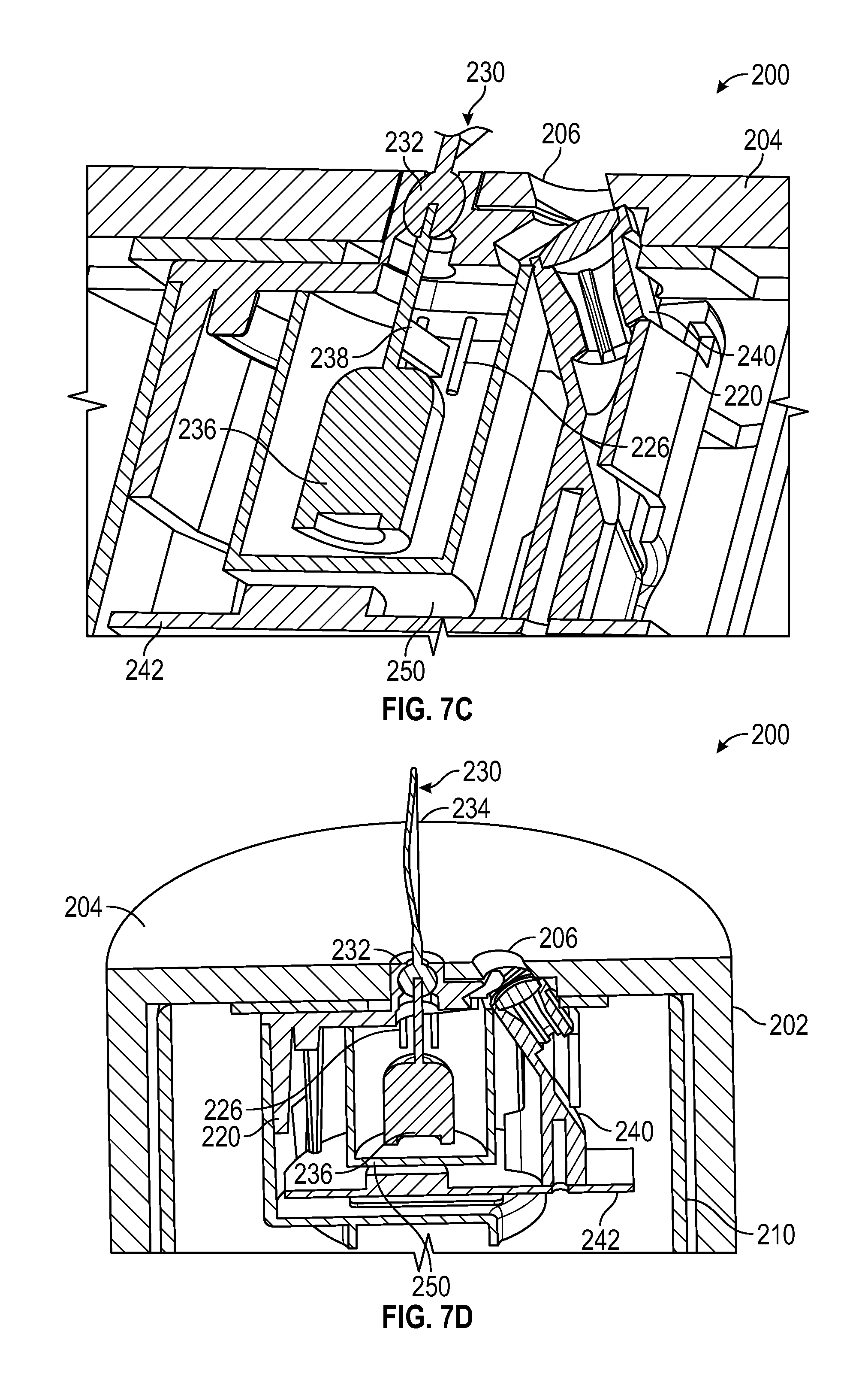
FIGS. 7A-7D illustrate another embodiment of an electric lighting device 200 comprising a cap 250 that is coupled to the housing 220 or shell 202, and configured to encapsulate the base 236 of the flame/pendulum member 230. The cap also holds circuit board 242, which includes a light source mounted on the circuit board. The cap 250 advantageously restricts a motion of the pendulum member 230 while also sealing the aperture in the upper surface 204 of shell 202. It is especially preferred that the cap 250 be affixed to the shell 202 via ultrasonic welding or other commercially suitable manner. In such embodiments, housing 220 could be eliminated as well as inner shell 210. Cap 250 preferably comprises a plastic or other material that will have little to no impact on the magnetic field generated by the electromagnet. In one embodiment shown in FIG. 7A, the flame member 230 can include wings 226, or any of the other projections shown in FIGS. 5A-5C.
FIGS. 8A-8B illustrate yet another embodiment of an electric lighting device 300, in which the housing has been eliminated. This advantageously reduces the number of components required for manufacture and simplifies assembly of the device 300, thereby reducing overall cost of manufacture. Cap 350 is coupled to the inner shell 310 via fasteners that extend through receptors 329 of the cap 350 and receptors 312 that are integral with the inner shell 310. With the housing eliminated, the circuit board 342 can be coupled to the inner shell via supports 352. Preferably, an electromagnet and light source holder 340 are disposed on the board 342 and supported by inner shell 310. With respect to the remaining numerals in FIGS. 8A-8B, the same considerations for like components with like numerals of FIGS. 1A-1D apply.
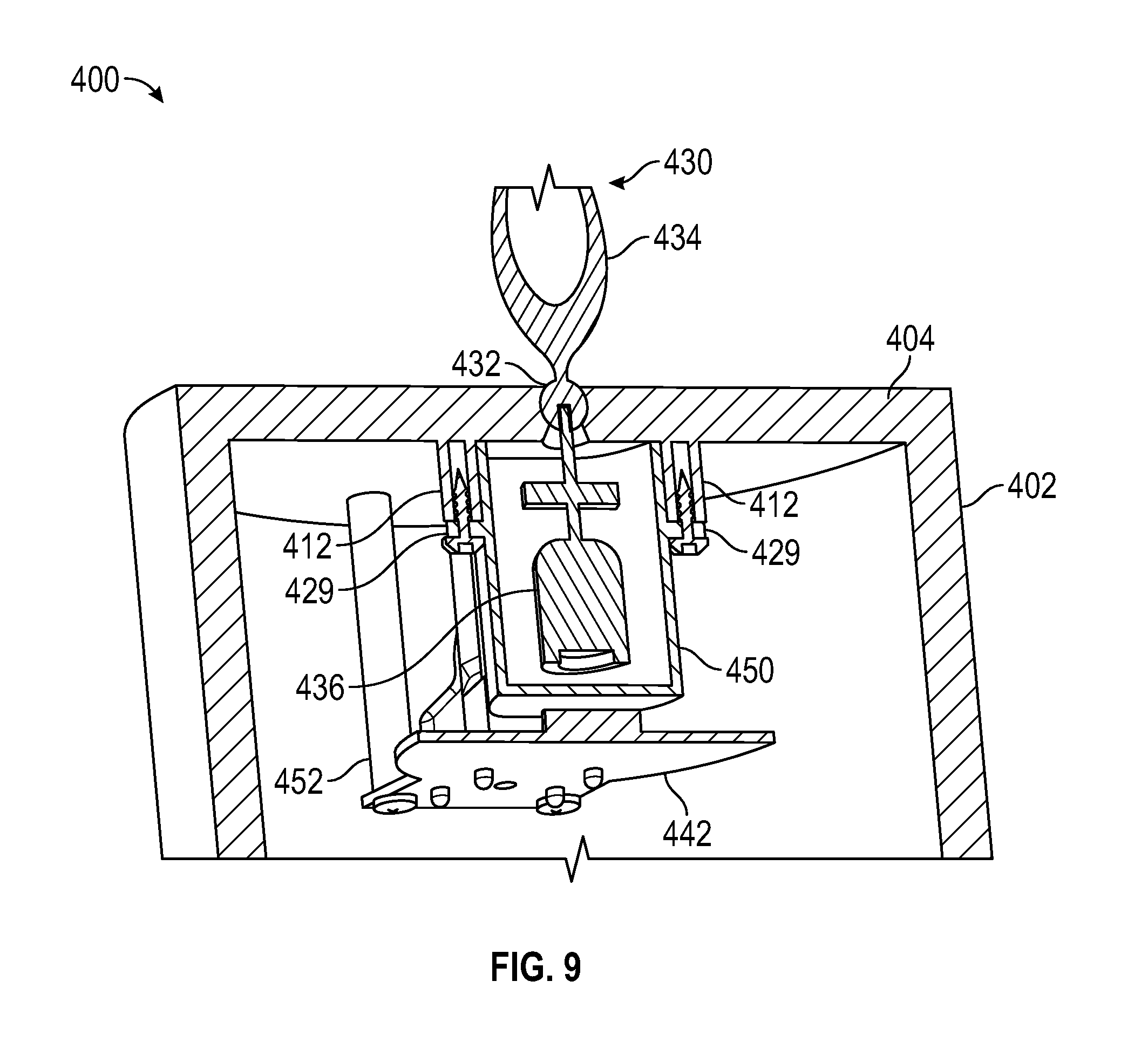
In still further embodiments shown in FIG. 9, both the housing and inner shell can be eliminated from the device 400, leaving the outer shell 402. In such embodiments, it is contemplated that the cap 450 can be attached directly to the outer shell 402 via fasteners that are inserted into receptors 429 and 412. Similarly, the circuit board 442 can be attached to the outer shell 402 via supports 452. With respect to the remaining numerals in FIG. 9, the same considerations for like components with like numerals of FIGS. 1A-1D apply
As used in the description herein and throughout the claims that follow, the meaning of "a," "an," and "the" includes plural reference unless the context clearly dictates otherwise. Also, as used in the description herein, the meaning of "in" includes "in" and "on" unless the context clearly dictates otherwise.
Also, as used herein, and unless the context dictates otherwise, the term "coupled to" is intended to include both direct coupling (in which two elements that are coupled to each other contact each other) and indirect coupling (in which at least one additional element is located between the two elements). Therefore, the terms "coupled to" and "coupled with" are used synonymously.
In some embodiments, the numbers expressing quantities of ingredients, properties such as concentration, reaction conditions, and so forth, used to describe and claim certain embodiments of the invention are to be understood as being modified in some instances by the term "about." Accordingly, in some embodiments, the numerical parameters set forth in the written description and attached claims are approximations that can vary depending upon the desired properties sought to be obtained by a particular embodiment. In some embodiments, the numerical parameters should be construed in light of the number of reported significant digits and by applying ordinary rounding techniques. Notwithstanding that the numerical ranges and parameters setting forth the broad scope of some embodiments of the invention are approximations, the numerical values set forth in the specific examples are reported as precisely as practicable. The numerical values presented in some embodiments of the invention may contain certain errors necessarily resulting from the standard deviation found in their respective testing measurements. Moreover, and unless the context dictates the contrary, all ranges set forth herein should be interpreted as being inclusive of their endpoints and open-ended ranges should be interpreted to include only commercially practical values. Similarly, all lists of values should be considered as inclusive of intermediate values unless the context indicates the contrary.
Thus, it should be apparent, however, to those skilled in the art that many more modifications besides those already described are possible without departing from the inventive concepts herein. The inventive subject matter, therefore, is not to be restricted except in the spirit of the disclosure. Moreover, in interpreting the disclosure all terms should be interpreted in the broadest possible manner consistent with the context. In particular the terms "comprises" and "comprising" should be interpreted as referring to the elements, components, or steps in a non-exclusive manner, indicating that the referenced elements, components, or steps can be present, or utilized, or combined with other elements, components, or steps that are not expressly referenced.
* * * * *
References
D00000
D00001
D00002
D00003
D00004
D00005
D00006
D00007
D00008
D00009
D00010
D00011
D00012
XML
uspto.report is an independent third-party trademark research tool that is not affiliated, endorsed, or sponsored by the United States Patent and Trademark Office (USPTO) or any other governmental organization. The information provided by uspto.report is based on publicly available data at the time of writing and is intended for informational purposes only.
While we strive to provide accurate and up-to-date information, we do not guarantee the accuracy, completeness, reliability, or suitability of the information displayed on this site. The use of this site is at your own risk. Any reliance you place on such information is therefore strictly at your own risk.
All official trademark data, including owner information, should be verified by visiting the official USPTO website at www.uspto.gov. This site is not intended to replace professional legal advice and should not be used as a substitute for consulting with a legal professional who is knowledgeable about trademark law.