Generating motor control reference signal with control voltage budget
Kleinau , et al. A
U.S. patent number 10,389,289 [Application Number 14/614,016] was granted by the patent office on 2019-08-20 for generating motor control reference signal with control voltage budget. This patent grant is currently assigned to Steering Solutions IP Holding Corporation. The grantee listed for this patent is STEERING SOLUTIONS IP HOLDING CORPORATION. Invention is credited to Siddharth Ballal, Julie A. Kleinau.


| United States Patent | 10,389,289 |
| Kleinau , et al. | August 20, 2019 |
Generating motor control reference signal with control voltage budget
Abstract
A method of controlling a motor in a motor control system is provided. The method determines a control voltage budget value based on an operating region of the motor. The method adjusts a supply voltage signal based on the control voltage budget value. The method determines a motor voltage command based on the adjusted supply voltage signal. The method applies a voltage corresponding to the motor voltage command to the motor in order to generate a desired motor torque.
| Inventors: | Kleinau; Julie A. (Bay City, MI), Ballal; Siddharth (Saginaw, MI) | ||||||||||
|---|---|---|---|---|---|---|---|---|---|---|---|
| Applicant: |
|
||||||||||
| Assignee: | Steering Solutions IP Holding
Corporation (Saginaw, MI) |
||||||||||
| Family ID: | 53755661 | ||||||||||
| Appl. No.: | 14/614,016 | ||||||||||
| Filed: | February 4, 2015 |
Prior Publication Data
| Document Identifier | Publication Date | |
|---|---|---|
| US 20150222210 A1 | Aug 6, 2015 | |
Related U.S. Patent Documents
| Application Number | Filing Date | Patent Number | Issue Date | ||
|---|---|---|---|---|---|
| 61936387 | Feb 6, 2014 | ||||
| Current U.S. Class: | 1/1 |
| Current CPC Class: | H02P 6/00 (20130101); H02P 21/22 (20160201); H02P 7/00 (20130101) |
| Current International Class: | B60L 15/02 (20060101); H02P 1/00 (20060101); H02P 7/00 (20160101); H02P 6/00 (20160101); H02P 21/22 (20160101) |
| Field of Search: | ;318/400.02,807,808,400.15 |
References Cited [Referenced By]
U.S. Patent Documents
| 4713596 | December 1987 | Bose |
| 4733149 | March 1988 | Culberson |
| 4920306 | April 1990 | Mard et al. |
| 5196778 | March 1993 | Hayashida |
| 5223775 | June 1993 | Mongeau |
| 5410234 | April 1995 | Shibata et al. |
| 5652495 | July 1997 | Narazaki et al. |
| 5927430 | July 1999 | Mukai et al. |
| 5962999 | October 1999 | Nakamura et al. |
| 6002234 | December 1999 | Ohm et al. |
| 6021251 | February 2000 | Hammer |
| 6104148 | August 2000 | Kumar |
| 6152254 | November 2000 | Phillips |
| 6161068 | December 2000 | Kurishige et al. |
| 6222334 | April 2001 | Tamagawa et al. |
| 6288515 | September 2001 | Hiti et al. |
| 6370459 | April 2002 | Phillips |
| 6465975 | October 2002 | Naidu |
| 6499559 | December 2002 | McCann et al. |
| 6605912 | August 2003 | Bharadwaj et al. |
| 6700342 | March 2004 | Hampo et al. |
| 6900607 | May 2005 | Kleinau et al. |
| 7034493 | April 2006 | Yoshimoto et al. |
| 7071649 | July 2006 | Shafer et al. |
| 7145310 | December 2006 | Ihm et al. |
| 7199549 | April 2007 | Kleinau et al. |
| 7207412 | April 2007 | Uryu |
| 7394214 | July 2008 | Endo et al. |
| 7548035 | June 2009 | Endo et al. |
| 7576506 | September 2009 | Kleinau et al. |
| 7952308 | May 2011 | Schulz et al. |
| 8633766 | January 2014 | Khlat et al. |
| 8896244 | November 2014 | Kleinau |
| 8952637 | February 2015 | Suzuki |
| 2002/0175649 | November 2002 | Reutlinger |
| 2003/0076065 | April 2003 | Shafer et al. |
| 2003/0146041 | August 2003 | Kanda |
| 2004/0095089 | May 2004 | Collier-Hallman |
| 2004/0195993 | October 2004 | Yoshimoto et al. |
| 2005/0073280 | April 2005 | Yoshinaga et al. |
| 2006/0000209 | January 2006 | Tsuda et al. |
| 2006/0100766 | May 2006 | Schwarz et al. |
| 2006/0113929 | June 2006 | DeLange |
| 2006/0122751 | June 2006 | Oyama et al. |
| 2006/0145639 | July 2006 | Song et al. |
| 2007/0043490 | February 2007 | Yokota et al. |
| 2007/0046126 | March 2007 | Sagoo et al. |
| 2007/0103105 | May 2007 | Endo et al. |
| 2007/0132446 | June 2007 | Kleinau et al. |
| 2007/0177314 | August 2007 | Weng et al. |
| 2007/0278032 | December 2007 | Sakaguchi et al. |
| 2008/0067960 | March 2008 | Maeda et al. |
| 2008/0167779 | July 2008 | Suzuki |
| 2008/0191656 | August 2008 | Satake et al. |
| 2008/0265808 | October 2008 | Sparey et al. |
| 2009/0026994 | January 2009 | Namuduri et al. |
| 2009/0027000 | January 2009 | Gallegos-Lopez et al. |
| 2009/0069979 | March 2009 | Yamashita et al. |
| 2009/0114470 | May 2009 | Shimizu et al. |
| 2009/0115362 | May 2009 | Saha |
| 2009/0189555 | July 2009 | Chen |
| 2009/0224710 | September 2009 | Mir |
| 2009/0234538 | September 2009 | Ta et al. |
| 2009/0267555 | October 2009 | Schulz et al. |
| 2010/0140003 | June 2010 | Saha et al. |
| 2010/0153162 | June 2010 | Tam et al. |
| 2010/0231148 | September 2010 | Tobari |
| 2011/0018281 | January 2011 | Tan et al. |
| 2011/0127934 | June 2011 | Suzuki |
| 2011/0156632 | June 2011 | Cheng |
| 2011/0169432 | July 2011 | Dean |
| 2011/0175556 | July 2011 | Tobari |
| 2011/0204833 | August 2011 | Santo et al. |
| 2011/0231066 | September 2011 | Ohno et al. |
| 2011/0297475 | December 2011 | Taniguchi et al. |
| 2011/0309781 | December 2011 | Tomigashi |
| 2012/0112549 | May 2012 | Perisic et al. |
| 2012/0221208 | August 2012 | Kojo et al. |
| 2012/0313701 | December 2012 | Khlat et al. |
| 2013/0013154 | January 2013 | Aoki |
| 2013/0154524 | June 2013 | Kleinau |
| 2013/0187579 | July 2013 | Rozman et al. |
| 2013/0261896 | October 2013 | Gebregergis et al. |
| 2013/0285591 | October 2013 | Suzuki |
| 2014/0191699 | July 2014 | Dixon |
| 2014/0239860 | August 2014 | Kleinau |
| 2014/0265961 | September 2014 | Gebregergis et al. |
| 2014/0265962 | September 2014 | Gebregergis et al. |
| 2014/0285129 | September 2014 | Maeda |
| 2014/0375239 | December 2014 | Kim et al. |
| 2015/0069941 | March 2015 | Iwaji et al. |
| 2015/0155811 | June 2015 | Merienne |
| 2015/0194919 | July 2015 | Merienne et al. |
| 2015/0372623 | December 2015 | Pramod et al. |
| 2016/0056745 | February 2016 | Ootake et al. |
| 1675099 | Sep 2005 | CN | |||
| 1741368 | Mar 2006 | CN | |||
| 101218146 | Jul 2008 | CN | |||
| 101399516 | Apr 2009 | CN | |||
| 101456429 | Jun 2009 | CN | |||
| 101615791 | Dec 2009 | CN | |||
| 101981804 | Feb 2011 | CN | |||
| 102570476 | Jul 2012 | CN | |||
| 102582679 | Jul 2012 | CN | |||
| 102751936 | Oct 2012 | CN | |||
| 1378419 | Jan 2004 | EP | |||
| 1720242 | Nov 2006 | EP | |||
| 1768252 | Mar 2007 | EP | |||
| 1914878 | Apr 2008 | EP | |||
| 2003010 | Dec 2008 | EP | |||
| 2293428 | Mar 2011 | EP | |||
| 2000108916 | Apr 2000 | JP | |||
| 2001247049 | Sep 2001 | JP | |||
| 2003170850 | Jun 2003 | JP | |||
| 2007137272 | Jun 2007 | JP | |||
| 2008143200 | Jun 2008 | JP | |||
| 2012224258 | Nov 2012 | JP | |||
| 2014006329 | Jan 2014 | WO | |||
Other References
|
F Briz, M.W. Degner and R.D. Lorenz; "Analysis and Design of Current Regulators Using Complex Vectors"; IEEE Industry Applications Society; Annual Meeting; New Orleans, Louisiana; Oct. 5-9, 1997; pp. 1504-1511. cited by applicant . Kirtley, J.; "6.061 Introduction to Electric Power Systems, Class Notes Chapter 12 Permanent Magnet `Brushless DC`" Motors, Massachussetts Institute of Technology, Department of Electrical Engineering and Computer Science, Spring 2011. cited by applicant . L. Harnefors, et al., "Model-Based Current Control of AC Machines Using the Internal Model Control Method", IEEE Transactions on Industry Applications, vol. 34, No. 1, Jan./Feb. 1998, pp. 133-141. cited by applicant . Jeong et al., "Fault Detection and Fault-Tolerant Control of Interior Permanent-Magnet Motor Drive System for Electric Vehicle", IEEE Transactions on Industry Applications, vol. 41, No. 1, Jan./Feb. 2005, pp. 46-51. cited by applicant . Li Yituo et al., PMSM current harmonics suppression based on feedforward compensation, Journal of Tsinghua University (Science and Technology), Mar. 2012, vol. 52, No. 3, Beijing, China, English Abstract, 1 page. cited by applicant . A. Madani, et al.,"Reduction of Torque Pulsations by Inductance Harmonics Identification of a Permanent-Magnet Synchronous Machine", IEEE, Sep. 28, 1995, p. 1-6. cited by applicant . European Patent Search; International Application No. EP14158556; International Filing Date: Jan. 8, 2017; dated Jul. 31, 2017; 9 pages. cited by applicant . European Patent Search; International Application No. EP14158559; International Filing Date: Jan. 8, 2017; dated Aug. 1, 2017; 7 pages. cited by applicant . European Search Report cited in Application No. 13 160 793.9 dated May 2, 2017, 11 pgs. cited by applicant . European Office Action cited in Application No. 13 160 793.9 dated Jun. 27, 2018, 5 pgs. cited by applicant. |
Primary Examiner: Santana; Eduardo Colon
Assistant Examiner: Cook; Cortez M
Parent Case Text
CROSS-REFERENCES TO RELATED APPLICATIONS
This patent application claims priority to U.S. Provisional Patent Application Ser. No. 61/936,387, filed Feb. 6, 2014, which is incorporated herein by reference in its entirety.
Claims
Having thus described the invention, it is claimed:
1. A method of controlling a motor in a motor control system, the method comprising: receiving a supply voltage signal and a motor torque command, the motor torque command specifying a desired motor torque to be generated by an electric motor; determining a control voltage budget value based on an operating region of the motor, the control voltage budget value being a retained portion of an available supply voltage; adjusting the supply voltage signal based on the control voltage budget value by subtracting the control voltage budget value from the supply voltage signal; determining a reference current command based on the adjusted supply voltage signal; and applying the reference current command to a current regulator, the current regulator configured to generate a motor voltage command to the motor based on the reference current command, the motor voltage command configured to cause the motor to generate the desired motor torque.
2. The method of claim 1, wherein the adjusted supply signal is less than the received supply voltage signal, and adjusting the supply voltage signal comprises subtracting the control voltage budget value from the supply voltage signal.
3. The method of claim 1, wherein the reference current command has a value such that, in combination with the adjusted supply signal, the current regulator causes the motor to achieve a desired voltage.
4. The method of claim 3, wherein determining the control voltage budget value comprises using a lookup table in which different control voltage budget values are indexed by different motor quadrant values and different motor velocity values.
5. The method of claim 4, wherein the control voltage budget values in the lookup table are predetermined through analysis as a function of at least one of a control loop bandwidth and dynamic response characteristics.
6. The method of claim 4, wherein the control voltage budget values in the lookup table are predetermined to be zeros for motor velocity values that are within a threshold difference from a zero motor velocity and to be gradually larger values as the motor velocity increases and control loop voltage requirements approach a supply voltage limit.
7. The method of claim 3, wherein determining the control voltage budget value comprises calculating the control voltage budget value as a function of a motor quadrant and a motor velocity.
8. The method of claim 3, wherein the current regulator is configured to perform a closed loop feedback control, the closed loop feedback control including receiving a measured motor current and generating the motor voltage command based on the reference current command and the measured motor current.
9. The method of claim 1, wherein the control voltage budget value for a particular motor torque command value and a particular motor velocity value is larger when the motor torque command and the motor velocity are in a same rotational direction of the motor than the control voltage budget value is when the motor torque command and the motor velocity are in different rotational directions of the motor.
10. The method of claim 1, wherein the motor is a DC (direct current) brush motor, wherein the determining the control voltage budget value comprises setting the control voltage budget value to a constant regardless of the operating region of the motor.
11. A motor control system, comprising: a motor; a control module configured to: receive a supply voltage signal and a motor torque command, the motor torque command specifying a desired motor torque to be generated by an electric motor; determine a control voltage budget value based on an operating region of the motor, the control voltage budget value being a retained portion of an available supply voltage; adjust the supply voltage signal based on the control voltage budget value by subtracting the control voltage budget value from the supply voltage signal; determine a reference current command based on the adjusted supply voltage signal; and apply the reference current command to a current regulator, the current regulator configured to generate a motor voltage command to the motor based on the reference current command, the motor voltage command configured to cause the motor to generate the desired motor torque.
12. The system of claim 11, wherein the control module is configured to adjust the supply voltage signal by subtracting the control voltage budget value from the supply voltage signal.
13. The system of claim 11, wherein the operating region of the motor comprises at least one of a motor quadrant, a motor velocity, and a motor load.
14. The system of claim 13, wherein the control module is configured to determine the control voltage budget value by using a lookup table in which different control voltage budget values are indexed by different motor quadrant values and different motor velocity values.
15. The system of claim 14, wherein the control voltage budget values in the lookup table are predetermined through analysis as a function of at least one of a control loop bandwidth and dynamic response characteristics.
16. The system of claim 14, wherein the control voltage budget values in the lookup table are predetermined to be zeros for motor velocity values that are within a threshold difference from a zero motor velocity and to be gradually larger values as the motor velocity increases and control loop voltage requirements approach a supply voltage limit.
17. The system of claim 13, wherein the control module is further configured to determine the motor quadrant based on signs of the motor torque command and the motor velocity.
18. The system of claim 11, wherein the control voltage budget value for a particular motor torque command value and a particular motor velocity value is larger when the motor torque command and the motor velocity are in a same rotational direction of the motor than the control voltage budget value is when the motor torque command and the motor velocity are in different rotational directions of the motor.
19. The system of claim 11, wherein the motor is a DC (direct current) brush motor, wherein the determining the control voltage budget value comprises setting the control voltage budget value to a constant regardless of the operating region of the motor.
20. The system of claim 11, wherein the control module is further configured to scale the supply voltage signal with a scale factor prior to adjusting the supply voltage signal in order to account for inverter switching dead time.
Description
BACKGROUND OF THE INVENTION
Current mode control of a brushless motor is widely used in many industries and products. Some conventional motor control system creates an error signal by comparing a current reference signal and a measured current signal, and uses the error signal to adjust the voltage applied to a brushless motor using a voltage supply inverter. Some of the motor control systems utilize reference current signals for both the q (quadrature) and d (direct) axes of the motor, in order to utilize a minimum amount of motor current for a given motor torque command, motor velocity, and supply voltage. The minimum current reference command is used as the input to a feedback current control loop, where the measured current(s) are subtracted from the reference current(s) to generate error signals used within a PI (proportional-integral), PID (proportional-integral-derivative), or other control loop structure. However, the minimum current reference command may cause performance degradation when the control systems operate near the supply voltage limit.
SUMMARY OF THE INVENTION
In one embodiment of the invention, a method of controlling a motor in a motor control system is provided. The method determines a control voltage budget value based on an operating region of the motor. The method adjusts a supply voltage signal based on the control voltage budget value. The method determines a motor voltage command based on the adjusted supply voltage signal. The method applies a voltage corresponding to the motor voltage command to the motor in order to generate a desired motor torque.
In another embodiment of the invention, a motor control system is provided. The system comprises a motor and a control module. The control module is configured to determine a control voltage budget value based on an operating region of the motor. The control module is further configured to adjust a supply voltage signal based on the control voltage budget value. The control module is further configured to determine a motor voltage command based on the adjusted supply voltage signal. The control module is further configured to apply a voltage corresponding to the motor voltage command to the motor in order to generate a desired motor torque.
These and other advantages and features will become more apparent from the following description taken in conjunction with the drawings.
BRIEF DESCRIPTION OF THE DRAWINGS
The subject matter which is regarded as the invention is particularly pointed out and distinctly claimed in the claims at the conclusion of the specification. The foregoing and other features, and advantages of the invention are apparent from the following detailed description taken in conjunction with the accompanying drawings in which:
FIG. 1 depicts a schematic diagram of a motor control system in accordance with exemplary embodiments of the invention;
FIG. 2 depicts a control voltage budget determination module in accordance with exemplary embodiments of the invention;
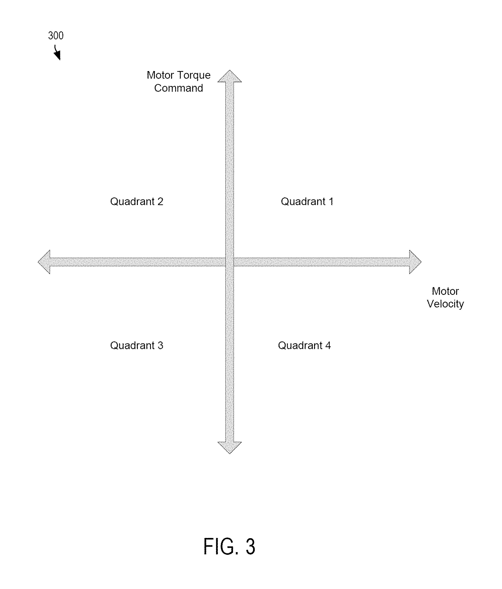
FIG. 3 depicts a graph showing a motor quadrant of operation in accordance with exemplary embodiments of the invention; and
FIG. 4 is flow diagram illustrating a control method for controlling an electric motor in accordance with exemplary embodiments of the invention.
DETAILED DESCRIPTION
The minimum current reference command discussed above is used as the input to a feedback current control loop of a motor control system, where the measured current(s) are subtracted from the reference current(s) to generate error signals used within a PI (proportional-integral), PID (proportional-integral-derivative), or other control loop structure. If the voltage required to produce the reference current command requires all of the available supply voltage, there will not be any remaining supply voltage to be used by the feedback portion of the control system. This changes the dynamics of the control system, with potential detrimental effects on bandwidth and stability/noise. Specifically, without any remaining supply voltage, closed current loop of current mode control dynamics are adversely affected. This may lead to noise and oscillations and leave no margin for an added ripple cancellation command. This in turn leads inaccurate errors signals.
Embodiments of the invention maintain a control voltage budget for operation of a closed loop feedback control. In some embodiments, a constant value of supply voltage may be preserved by subtracting that constant value from the measured supply voltage signal before calculation of the optimal reference current command. This will result in reference commands for the feedback control loop, which do not require the full supply voltage, to achieve a desired motor torque generated by the motor. The reference commands in this case would utilize more motor current, or a larger voltage phase angle, to achieve the desired torque.
When utilizing a constant control voltage budget throughout the motor operating space including areas where the control does not need to operate near the supply voltage limit, the reference command solution represents more motor current than required to deliver the specified torque. This may not be desirable for several reasons, including supply current use efficiency and motor thermal performance.
In some embodiments of the invention, a motor operating range is considered. A control voltage budget value is calculated based on an operating region of the motor control (at least one of motor quadrant, motor velocity, and motor load) in order to retain some of the available supply voltage. The budget value may be set to zero volts when not operating near the supply voltage limit. The budget value may be set to an appropriate value when operating near that voltage limit. The budget value is calibratable for the motor velocity, operational quadrant, and motor load.
FIG. 1 depicts a block diagram of a motor control system 100 for an electric motor (e.g., DC (direct current) brushless motor, a PMSM (permanent magnet synchronous machine), etc.) utilizing phase current measurements in a current control feedback loop in accordance with some embodiments of the invention. As shown, the motor control system 100 includes a control voltage budget determination module 102, a motor reference command generator module 104, and a current regulator module 106. FIG. 1 also depicts a motor 126. As used herein, the term "module" or "sub-module" refers to an application specific integrated circuit (ASIC), an electronic circuit, a processor (shared, dedicated, or group) and memory that executes one or more software or firmware programs, a combinational logic circuit, and/or other suitable components that provide the described functionality. When implemented in software, a module or a sub-module can be embodied in memory as a non-transitory machine-readable storage medium readable by a processing circuit and storing instructions for execution by the processing circuit for performing a method. Moreover, the modules and sub-modules shown in FIG. 1 may be combined and/or further partitioned.
The control voltage budget determination module 102 determines a control voltage budget value based on at least one of a motor quadrant, the motor velocity signal 112, and a motor load. A motor quadrant, in some embodiments, is a number between one and four that represents the relationship between the motor torque command 108 and the motor velocity signal 112, and is described in detail further below with reference to FIG. 3. The control voltage budget determination module 102 adjusts the supply voltage signal 110 based on the determined control voltage budget value. Specifically, in some embodiments, the control voltage budget value determination module 102 adjusts the supply voltage signal 110 by subtracting the determined control voltage budget value from the supply voltage signal 110. The control voltage budget determination module 102 supplies the adjusted supply voltage signal 116 to the motor reference command generator module 104. The control voltage determination module 102 will be described below in more detail with reference to FIG. 2.
The motor reference command generator module 104 generates a reference current command 118 and optionally a reference voltage command 120 based on input signals, including the motor torque command 108, the motor velocity signal 112, the adjusted supply voltage signal 116, and motor parameters 114. The motor torque command 108 represents a commanded torque value, and may be derived from another motor control system (not shown), or may correspond to a torque value generated by, for example, an operator of a vehicle by turning a hand wheel of the vehicle. The motor velocity signal 112 is an angular speed of the motor 126 measured by a speed sensor (not shown). The speed sensor may include, for example, an encoder and a speed calculation circuit for calculating the angular speed of a rotor of the motor 126 based on a signal received by the encoder.
The adjusted supply voltage signal 116 represents a bridge voltage from a direct current (DC) power source (not shown) that is adjusted by the control voltage determination module 102, as described above. The motor reference command generator module 104 treats the adjusted supply voltage signal 116 as the bridge voltage from the DC power source. The motor parameters 114 are estimated values for the motor 126, including, for example, a motor constant (K.sub.e), a motor circuit resistance (R), a direct axis inductance (L.sub.d) and a quadrature axis inductance (L.sub.q). K.sub.e is the motor voltage constant (Voltage/Radian/second). R is the motor circuit resistance, including the motor stator and controller hardware (Ohms). L.sub.q and L.sub.d are the stator quadrature-axis (q-axis) and direct-axis (d-axis) inductances, respectively (Henries).
In some embodiments, the reference current command 118 generated by the motor reference command generator module 104 includes a reference d-axis current command and a reference q-axis current command. The motor reference command generator module 104 may also calculate the reference voltage command 120 optionally, which may include a reference d-axis voltage command and a reference q-axis voltage command. The reference current command 118 and the reference voltage command 120 satisfy the motor torque command 108.
The current regulator module 106 determines a motor voltage command 122 based on the reference current command 118, the reference voltage command 120, and the measured motor currents 124. The measured motor currents 124 include a measured d-axis current and a measured q-axis current. In some embodiments, the current regulator module 106 calculates the discrepancy between the reference d-axis current command and the measured d-axis current as well as the discrepancy between the reference q-axis current command and the measured q-axis current. The current regulator module 106 uses the calculated discrepancies to determine the motor voltage command 122, which include a d-axis voltage command and a q-axis voltage command.
The current regulator module 106 applies a motor voltage according to the motor voltage command 122 to the motor 126 in order to control the motor. Specifically, in some embodiments, a polar conversion controller (not shown) receives as inputs the d-axis voltage command and the q-axis voltage command. Based on the inputs, the polar conversion controller determines a voltage command and a phase advance angle. A PWM (pulse-width modulation) inverter controller (not shown) then receives as input signals the voltage command and the phase advance angle from the polar conversion controller. The PWM inverter controller also receives a rotor angle value of the motor 126 measured by a motor position sensor (not shown). In some embodiments, the PWM inverter controller may include an over-modulation space vector PWM unit that generates three respective duty cycle values. The duty cycle values are used to drive gate drive circuits of an inverter (not shown) that energize phases of the motor 126.
For feedback control purposes, the current regulator module 106 receives measured motor currents 124 from the motor 126. Phase current measurement sensors (no shown) measure two phase currents drawn by the motor 126. The measured motor currents 124 therefore represent the values of the two phase currents measured by the measurement sensors. In some embodiments, the measured values for the AC current are converted into equivalent measured DC current components, which are a measured d-axis current and a measured q-axis current in the d-q reference frame.
The embodiments of the invention are described with an assumption that the motor 126 is a DC brushless motor. However, some embodiments of the invention may be extended to use a DC brush motor through use of a different reference model. In these embodiments, the control voltage budget determination module 102 sets the control voltage budget value to a constant value instead of having the control voltage budget depend from the motor velocity as a DC brush motor does not always have a motor velocity signal available.
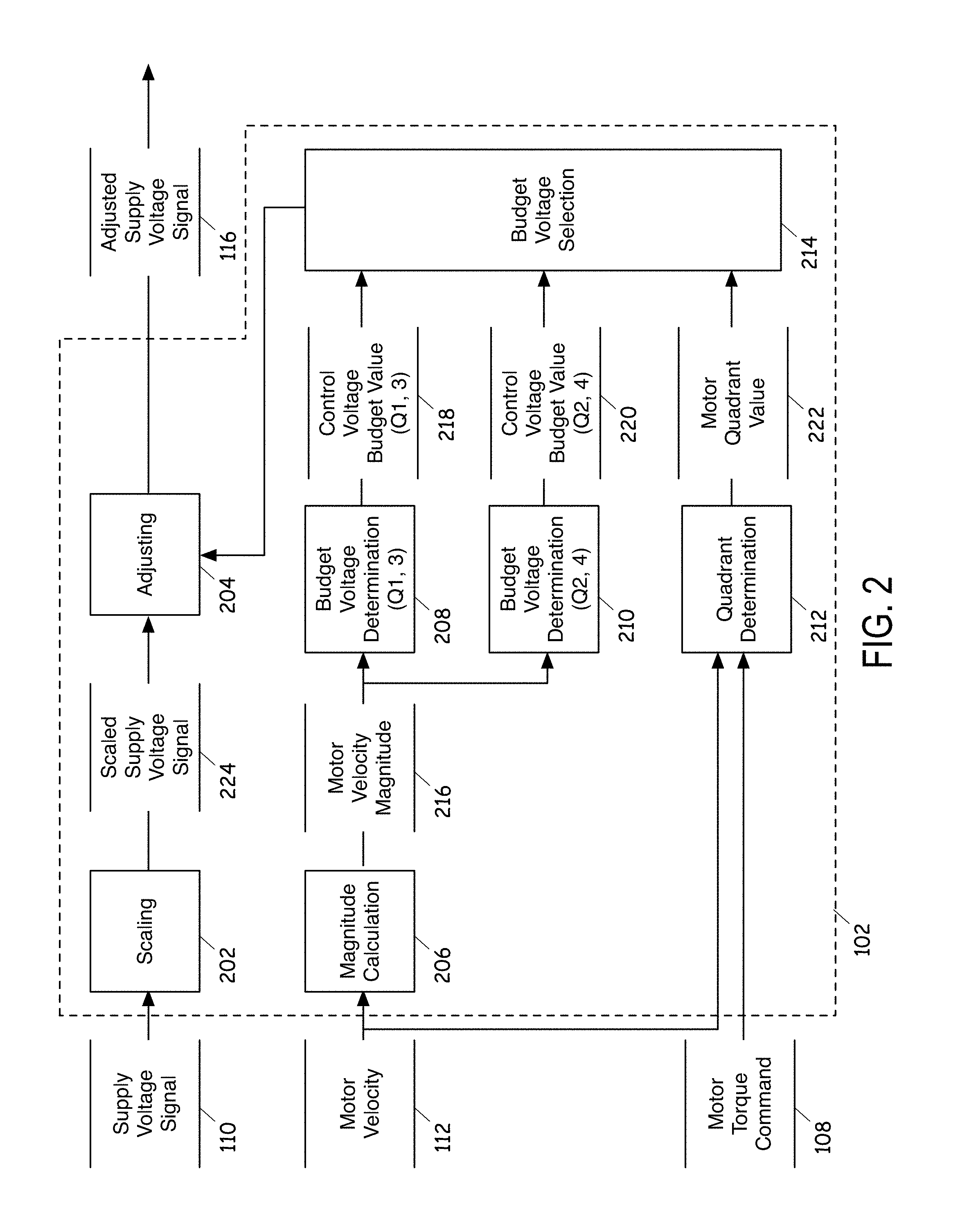
FIG. 2 illustrates a schematic diagram of the control voltage budget determination module 102 of FIG. 1 in accordance with exemplary embodiments of the invention. As shown, the control voltage budget determination module 102 may include submodules such as a scaling module 202, an adjusting module 204, a magnitude calculation module 206, budget determination modules 208 and 210, a quadrant determination module 212, and a budget voltage selection module 214.
The quadrant determination module 212 determines a motor quadrant value 222 based on the motor torque command 108 and the motor velocity signal 112. A motor quadrant, in some embodiments, is a number between one and four that represents the relationship between the motor torque command 108 and the motor velocity 112. FIG. 3 shows a graph 300 having the four quadrants. The first quadrant (quadrant 1) indicates that both motor torque command 108 and the motor velocity signal 112 are the positive rotational direction of the motor 126. The second quadrant (quadrant 2) indicates that the motor torque command is in the positive rotational direction while the motor velocity signal 112 is in the negative rotational direction. The third quadrant (quadrant 3) indicates that indicates that both motor torque command 108 and the motor velocity signal 112 are the negative rotational direction of the motor 126. The fourth quadrant (quadrant 4) indicates that the motor torque command is in a negative rotational direction while the motor velocity signal 112 is in the positive rotational direction. In other words, the first and third quadrants indicate that both of the motor torque command 108 and the motor velocity signal 112 are in the same rotational direction, while the second and fourth quadrants indicate that the motor torque command 108 and the motor velocity signal 112 are in different rotational directions.
Referring back to FIG. 2, the magnitude calculation 206 takes a magnitude or an absolute value of the motor velocity signal 112. The motor velocity magnitude 216 of the motor velocity signal 112 is then supplied to the budget voltage determination modules 208 and 210. The budget voltage determination module 208 determines a control voltage budget value 218 for quadrants 1 and 3 based on the motor velocity magnitude 216 and/or the motor load (not shown) of the motor 126. Specifically, in some embodiments, the budget voltage determination module 208 uses a lookup table for quadrants 1 and 3. In this lookup table, different control voltage budget values are indexed by different motor velocity magnitude values, to determine control voltage budget value for the motor velocity magnitude 216. In some embodiments, the budget voltage determination module 208 calculates the control voltage budget value 218 as a function of the motor velocity magnitude 216.
Similarly, the budget voltage determination module 210 determines a control voltage budget value 220 for quadrants 2 and 4 based on the motor velocity magnitude 216 and/or the motor load. The budget voltage determination module 210 may use a lookup table for quadrants 2 and 4, in which different control voltage budget values are indexed by different motor velocity magnitude values, to determine control voltage budget value for the motor velocity magnitude 216. In some embodiments, the budget voltage determination module 210 calculates the control voltage budget value 218 as a function of the motor velocity magnitude 216.
The budget voltage selection module 214 selects one of the control voltage budget value 218 and the control voltage budget value 220 based on the motor quadrant value 222. That is, if the motor quadrant value 222 indicates the quarter in which the motor 126 is quarter 1 or 3, the budget voltage selection module 314 selects the control voltage budget value 218 determined by the budget voltage determination module 208. If the motor quadrant value 222 indicates the quarter in which the motor 126 is quarter 2 or 4, the budget voltage selection module 316 selects the control voltage budget value 220 determined by the budget voltage determination module 210. The budget voltage selection module 214 sends the selected control voltage budget value 218 or 220 to the adjusting module 204.
Determination and selection of a control budget value is performed by the budget voltage determination modules 208 and 210 and the budget voltage selection 214 using multiple lookup tables or functions. One of the ordinary skill in the art will recognize that determination and selection of a control budget value may also be accomplished by using a single lookup table or a single function. Such a lookup table has different control voltage budget values indexed by different motor velocity magnitude values. Or, the control voltage budget values may be calculated as a function of the motor velocity magnitude 216 and the motor quadrant value 222.
The control voltage budget values in the lookup table(s) are predetermined through analysis as a function of the control loop bandwidth, the dynamic response characteristics and/or other control loop requirements, such as the need for addition of a torque ripple cancelling signal. The control voltage budget values are predetermined based on the expected voltage transients required from the closed loop current control in the current regulator module 106. These expected transients vary with respect to multiple aspects of the control system design, such as the motor parameters 114 (e.g., K.sub.e R L.sub.q and L.sub.d), the control loop bandwidth and/or the control loop requirements.
The predetermined values of the control voltage budget would be zero at and near zero motor velocity (i.e., within a threshold difference from zero motor velocity), with gradually increasing values as the motor velocity increases and the control loop voltage requirements approach the supply voltage limit. The zero voltage budget value may be maintained to a higher motor velocity in quadrants 2 and 4 versus quadrants 1 and 3, as the motor BEMF (back electro-magnetic force) voltage adds to the supply voltage in quadrants 2 and 4.
The scaling module 202 is an optional module of the control voltage budget determination module 102 and scales the supply voltage signal 110 with a calibration value in order to account for inverter switching dead time. Due to the dead time characteristics of some inverter designs, the full supply voltage may not be available to apply to the motor. The scaling allows the supply voltage signal 110 to uniquely reflect that behavior. A typical value for this calibration scale factor would be 0.99. The scaling module 202 sends the scaled supply voltage signal 224 to the adjusting module 204.
The adjusting module 204 adjusts the scaled supply voltage signal 322 or the supply voltage signal 110 using the control voltage budget value selected by the budget voltage selection 314. Specifically, in some embodiments, the adjusting module 204 subtracts the selected control voltage budget value from the scaled supply voltage signal 322 or the supply voltage signal 110 to generate the adjusted supply voltage signal 116.
FIG. 4 is a flow diagram for a control method that can be performed by the motor control system 100 in accordance with some embodiments of the invention. As can be appreciated in light of the disclosure, the order of operation within the method is not limited to the sequential execution as illustrated in FIG. 4, but may be performed in one or more varying orders as applicable and in accordance with the present disclosure.
At block 410, the system 100 determines a control voltage budget value based on an operating region of the motor, which, in some embodiments, includes at least one of a motor quadrant, a motor velocity, and a motor load. In some embodiments, the system 100 determines the motor quadrant based on signs of the motor torque command and the motor velocity.
In some embodiments, the system 100 determines the control voltage budget value by using a lookup table in which different control voltage budget values are indexed by different motor quadrant values and different motor velocity values. The control voltage budget values in the lookup table are predetermined through analysis as a function of at least one of a control loop bandwidth and dynamic response characteristics. The control voltage budget values in the lookup table are predetermined to be zeros for motor velocity values that are within a threshold difference from a zero motor velocity and to be gradually larger values as the motor velocity increases and control loop voltage requirements approach a supply voltage limit. The control voltage budget value for a particular motor torque command value and a particular motor velocity value is larger when the motor torque command and the motor velocity are in a same rotational direction of the motor than the control voltage budget value is when the motor torque command and the motor velocity are in different rotational directions of the motor.
In some embodiments, the system 100 determines the control voltage budget value by directly calculating through a functional relationship the control voltage budget value as a function of the motor quadrant and the motor velocity, instead of using a lookup table.
In some embodiments, the motor is a DC brushless motor. In other embodiments, the motor is a DC brush motor. In some such embodiments, the system 100 sets the control voltage budget value to a constant regardless of the operating region of the motor.
At block 420, the system 100 adjusts a supply voltage signal based on the control voltage budget value. Specifically, in some embodiments, the system 100 adjusts the control voltage budget by subtracting the control voltage budget value from the supply voltage signal. In some embodiments, the system 100 may also scale the supply voltage signal with a scale factor prior to adjusting the supply voltage signal in order to account for inverter switching dead time.
At block 430, the system 100 determines a motor voltage command based on the adjusted supply voltage signal. At block 440, the system 100 causes the motor to generate torque based on the motor voltage command. That is, the system 100 applies a voltage corresponding to the motor voltage command to the motor in order to generate a desired motor torque.
While the invention has been described in detail in connection with only a limited number of embodiments, it should be readily understood that the invention is not limited to such disclosed embodiments. Rather, the invention can be modified to incorporate any number of variations, alterations, substitutions or equivalent arrangements not heretofore described, but which are commensurate with the spirit and scope of the invention. Additionally, while various embodiments of the invention have been described, it is to be understood that aspects of the invention may include only some of the described embodiments. Accordingly, the invention is not to be seen as limited by the foregoing description.
* * * * *
D00000
D00001
D00002
D00003
D00004
XML
uspto.report is an independent third-party trademark research tool that is not affiliated, endorsed, or sponsored by the United States Patent and Trademark Office (USPTO) or any other governmental organization. The information provided by uspto.report is based on publicly available data at the time of writing and is intended for informational purposes only.
While we strive to provide accurate and up-to-date information, we do not guarantee the accuracy, completeness, reliability, or suitability of the information displayed on this site. The use of this site is at your own risk. Any reliance you place on such information is therefore strictly at your own risk.
All official trademark data, including owner information, should be verified by visiting the official USPTO website at www.uspto.gov. This site is not intended to replace professional legal advice and should not be used as a substitute for consulting with a legal professional who is knowledgeable about trademark law.