Sample injector for liquid chromatography, particularly for high performance liquid chromatography
Hochgraeber A
U.S. patent number 10,386,342 [Application Number 16/212,914] was granted by the patent office on 2019-08-20 for sample injector for liquid chromatography, particularly for high performance liquid chromatography. This patent grant is currently assigned to Dionex Softron GMBH. The grantee listed for this patent is DIONEX SOFTRON GMBH. Invention is credited to Hermann Hochgraeber.


| United States Patent | 10,386,342 |
| Hochgraeber | August 20, 2019 |
| **Please see images for: ( Certificate of Correction ) ** |
Sample injector for liquid chromatography, particularly for high performance liquid chromatography
Abstract
A sample injection method for liquid chromatography is performed with an injection valve having a waste port, two sample loop ports, and two high-pressure ports. One high-pressure port can be connected to a pump and the other high-pressure port can be connected to a chromatography column. A sample loop is connected to one of the sample loop ports on one end and to a pump volume of a sample conveying device on the other end. A section of the sample loop can be separated to facilitate receiving a sample fluid in the sample loop. A control unit controls the injection valve and the sample conveying device. The sample injector allows a sample to be loaded into the sample loop and then pressurized to an operating pressure prior to injecting the sample into the chromatography column. The sample loop may also be isolated from the operating pressure for facilitating depressurization of the loop.
| Inventors: | Hochgraeber; Hermann (Offenberg-Neuhausen, DE) | ||||||||||
|---|---|---|---|---|---|---|---|---|---|---|---|
| Applicant: |
|
||||||||||
| Assignee: | Dionex Softron GMBH (Germering,
DE) |
||||||||||
| Family ID: | 40568221 | ||||||||||
| Appl. No.: | 16/212,914 | ||||||||||
| Filed: | December 7, 2018 |
Prior Publication Data
| Document Identifier | Publication Date | |
|---|---|---|
| US 20190113484 A1 | Apr 18, 2019 | |
Related U.S. Patent Documents
| Application Number | Filing Date | Patent Number | Issue Date | ||
|---|---|---|---|---|---|
| 16016866 | Jun 25, 2018 | ||||
| 15596738 | May 16, 2017 | 10031112 | |||
| 14454563 | Aug 7, 2014 | ||||
| 12863976 | 8806922 | ||||
| PCT/DE2009/000004 | Jan 7, 2009 | ||||
Foreign Application Priority Data
| Jan 25, 2008 [DE] | 10 2008 006 266 | |||
| Current U.S. Class: | 1/1 |
| Current CPC Class: | G01N 35/1097 (20130101); G01N 30/32 (20130101); G01N 30/20 (20130101); G01N 30/24 (20130101); G01N 2030/201 (20130101); G01N 2030/027 (20130101); G01N 2030/207 (20130101) |
| Current International Class: | G01N 30/20 (20060101); G01N 30/32 (20060101); G01N 35/10 (20060101); G01N 30/24 (20060101); G01N 30/02 (20060101) |
References Cited [Referenced By]
U.S. Patent Documents
| 1577012 | March 1926 | Crane |
| 3530721 | September 1970 | Hrdina |
| 4068528 | January 1978 | Gundelfinger |
| 4182184 | January 1980 | Bakalyar et al. |
| 4300393 | November 1981 | Stearns |
| 4444066 | April 1984 | Ogle et al. |
| 4506558 | March 1985 | Bakalyar |
| 4883409 | November 1989 | Strohmeier et al. |
| 4939943 | July 1990 | Strohmeier |
| 5010921 | April 1991 | Nohl |
| 5105851 | April 1992 | Fogelman |
| 5108264 | April 1992 | Abdel-Rahman |
| 5207109 | May 1993 | Olsen |
| 5637208 | June 1997 | Dourdeville |
| 5730943 | March 1998 | Ford et al. |
| 5803117 | September 1998 | Olsen et al. |
| 6012487 | January 2000 | Hauck |
| 6129840 | October 2000 | Kitaoka |
| 6155123 | December 2000 | Bakalyar |
| 6260407 | July 2001 | Petro et al. |
| 6281019 | August 2001 | Werringloer |
| 6382035 | May 2002 | Nichols |
| 6416663 | July 2002 | Miroslav et al. |
| 6428702 | August 2002 | Berger et al. |
| 6475391 | November 2002 | Safir et al. |
| 6485642 | November 2002 | Kaito et al. |
| 6874354 | April 2005 | Cueni et al. |
| 6976383 | December 2005 | Petro et al. |
| 7377291 | May 2008 | Moon et al. |
| 7503203 | March 2009 | Gamache et al. |
| 7588725 | September 2009 | Ozbal et al. |
| 8196456 | June 2012 | Hochgraeber et al. |
| 8312762 | November 2012 | Fadgen et al. |
| 8806822 | August 2014 | Wang |
| 8806922 | August 2014 | Hochgraeber |
| 8921113 | December 2014 | Lin et al. |
| 9086426 | July 2015 | Liu et al. |
| 9435773 | September 2016 | Glatz et al. |
| 10031112 | July 2018 | Hochgraeber |
| 2002/0008058 | January 2002 | Nugent |
| 2003/0098076 | May 2003 | Nichols |
| 2005/0061722 | March 2005 | Takao et al. |
| 2005/0194318 | September 2005 | Ozbal et al. |
| 2006/0042686 | March 2006 | Gamache et al. |
| 2006/0191581 | August 2006 | Cueni et al. |
| 2006/0219618 | October 2006 | Witt et al. |
| 2006/0260700 | November 2006 | Bauerle et al. |
| 2007/0251302 | November 2007 | Iwata |
| 2008/0022765 | January 2008 | Witt et al. |
| 2008/0047611 | February 2008 | Stemer |
| 2009/0144520 | June 2009 | Hochgraeber et al. |
| 2009/0145205 | June 2009 | Hochgraeber et al. |
| 2010/0260617 | October 2010 | Haertl |
| 2010/0288025 | November 2010 | Hochgraeber |
| 2012/0132013 | May 2012 | Glatz et al. |
| 2013/0067997 | March 2013 | Ebsen et al. |
| 2014/0007660 | January 2014 | Moeller et al. |
| 2014/0197247 | July 2014 | Stearns et al. |
| 2014/0338431 | November 2014 | Hochgraeber |
| 2014/0345371 | November 2014 | Hochgraeber |
| 2014/0345372 | November 2014 | Gerhardt et al. |
| 2015/0265944 | September 2015 | Hochgraeber et al. |
| 1327157 | Dec 2001 | CN | |||
| 3223852 | Jan 1983 | DE | |||
| 19628206 | Jan 1998 | DE | |||
| 10222334 | Dec 2003 | DE | |||
| 102004052584 | Jan 2006 | DE | |||
| 112005000128 | May 2007 | DE | |||
| 102007059651 | Jun 2009 | DE | |||
| 102008006266 | Aug 2009 | DE | |||
| 112009000004 | Jul 2010 | DE | |||
| 102008006266 | Jun 2011 | DE | |||
| 102013215065 | Feb 2015 | DE | |||
| 0244751 | Nov 1987 | EP | |||
| 0321774 | Jun 1989 | EP | |||
| 0327658 | Aug 1989 | EP | |||
| 1536228 | Jun 2005 | EP | |||
| 1577012 | Sep 2005 | EP | |||
| 1879026 | Jan 2008 | EP | |||
| 2051071 | Apr 2009 | EP | |||
| 2196801 | Jun 2010 | EP | |||
| 54089692 | Jul 1979 | JP | |||
| S60143279 | Jul 1985 | JP | |||
| 62272155 | Nov 1987 | JP | |||
| 05307026 | Nov 1993 | JP | |||
| 07072130 | Mar 1995 | JP | |||
| H08159310 | Jun 1996 | JP | |||
| 3491948 | Feb 2004 | JP | |||
| 2006058146 | Mar 2006 | JP | |||
| 2007327845 | Dec 2007 | JP | |||
| 2007327846 | Dec 2007 | JP | |||
| 2008051746 | Mar 2008 | JP | |||
| 2008529010 | Jul 2008 | JP | |||
| 2009053098 | Mar 2009 | JP | |||
| WO-0239105 | May 2002 | WO | |||
| WO2004025272 | Mar 2004 | WO | |||
| 2006023828 | Mar 2006 | WO | |||
| WO2006083776 | Aug 2006 | WO | |||
| WO2006089389 | Oct 2006 | WO | |||
| 2007109529 | Sep 2007 | WO | |||
| 2008005845 | Jan 2008 | WO | |||
| WO2008103098 | Aug 2008 | WO | |||
| WO-2009003520 | Jan 2009 | WO | |||
| WO2009092345 | Jul 2009 | WO | |||
| 2009108219 | Sep 2009 | WO | |||
| 2009108219 | Sep 2009 | WO | |||
| 2010139359 | Dec 2010 | WO | |||
| WO-2014199198 | Dec 2014 | WO | |||
Other References
|
Agilent Technologies, Inc.; Agilent 1100 Series HPLC Value System; pp. 1-76, 1999. cited by applicant . Agilent Technologies; Agilent 1200 Series HPLC-Chip/MS System; pp. 1-8; Aug. 1, 2008. cited by applicant . Angelika Gratzfeld-Huesgen et al., Agilent 1200 Series Rapid Resolution LC and Rapid Resolution LD/MS Optimization Guide; Agilent Technologies; pp. 1-133, Jan. 2009. cited by applicant . Beinhauer et al., "Bulk derivatization and cation exchange restricted access media-based trap-and-elute liquid chromatography-mass spectrometry method for determination of trace estrogens in serum," Analytica Chimica Acta, 858, 74-81, 2015. cited by applicant . Brotto, Jun. 15, 2017, manuscript No. ACA-17-727, 95 pgs. cited by applicant . Canadian Office Action issued in CA app. No. 2,764,047, dated Jul. 10, 2015, 6 pgs. cited by applicant . Chinese-language Office Action (with English translation) issued in CN app. No. 200980159715.9 dated Oct. 15, 2013, 25 pgs. cited by applicant . COSMOS program for Aug. 17-19, 2015 Conference, http://www.cosmoscience.org/blog/archives/2015-cosmos/2015-agenda/ accessed Jun. 21, 2017, 18 pgs. cited by applicant . EP Communication pursuant to Article 94(3) EPC issued in EP app. No. 09779619.7 dated Jun. 27, 2013, 4 pgs. cited by applicant . EP Communication pursuant to Article 94(3) EPC issued in EP app. No. 09779619.7 dated Oct. 18, 2012, 6 pgs. cited by applicant . Excerpt from VICI AG Valco Cheminert Catalog (1999), 17 pgs. cited by applicant . Excerpt from VICI Valco Cheminert Catalog (2005), 27 pgs. cited by applicant . Fan and Schug, "Hyphenation of Flow-Injection Analysis with Mass Spectrometry: A Versatile and High-Throughput Technique," Current Trends in Mass Spectrometry, May 2012, 6 pgs. cited by applicant . Fan et al., "Bulk-derivatization and direct injection of human cerebrospinal fluid for trace-level quantification of endogenous estrogens using trap-and-elute liquid chromatography with tandem mass spectroscopy," J. Sep. Sci., 37, 2010-2017, 2014. cited by applicant . Final Office Action issued in U.S. Appl. No. 13/375,884, dated Mar. 1, 2016, 11 pgs. cited by applicant . Final Office Action issued in U.S. Appl. No. 14/877,758, dated Jun. 14, 2016, 15 pgs. cited by applicant . Fujinari, "New Alternative to Normal Phase HPLC Automation Using Methylene Chloride Mobile Phases: A Synchronized Dual Switching Valve Loop Injection System," Journal of High Resolution Chromatography & Chromatography Communications, Aug. 1988, pp. 595-598, No. 8, Heidelberg, W. Germany (4 pages). cited by applicant . International Search Report and Written Opinion issued in PCT/EP2009/056795, dated Jan. 13, 2010, 16 pgs. cited by applicant . Japanese-language Office Action issued in JP app. No. 2012-513477, dated Oct. 11, 2013 (with English translation), 6 pgs. cited by applicant . Kevin A. Schug, Ph.D., slide presentation for Aug. 17-19, 2015 Conference on Small Molecule Science, 32 pgs. cited by applicant . Kevin Schug, Ph.D., Chemistry Spring 2017 course syllabus for Instrumental Analysis, 30 pgs. cited by applicant . Kretz et al., "Automatic Liquid Chromatography Injection and Sampling," Hewlett-Packard Journal, Apr. 1984, 4 pgs. cited by applicant . Non-final Office Action issued in U.S. Appl. No. 14/877,758, dated Mar. 2, 2016, 19 pgs. cited by applicant . Notice of Allowance issued in U.S. Appl. No. 13/375,884, dated May 10, 2016, 11 pgs. cited by applicant . Papouskova et al., "Aspects of trapping efficiency and matrix effects in the development of a restricted-access-media-based trap-and-elute liquid chromatograhy with mass spectrometry method," J. Sep. Sci., 37, 2192-2199, 2014. cited by applicant . Preliminary amendment submitted in U.S. Appl. No. 13/375,884, filed Feb. 15, 2012, 10 pgs. cited by applicant . Priority document (translation from original German) submitted by Dionex on Jul. 21, 2010 to satisfy 35 U.S.C. 371(c) for National Stage Entry into US of PCT/DE2009/000004, 35 pgs. cited by applicant . U.S. Office Action issued in U.S. Appl. No. 13/375,884, dated Nov. 24, 2015, 17 pgs. cited by applicant . Yang et al., "Quantitative Determination of Bisphenol A From Human Saliva Using Bulk Derivatization and Trap-and-Elute Liquid Chromatography Coupled to Electrospray Ionization Mass Spectrometry," Environmental Toxicology and Chemistry, 30(6), 2011, 1243-1251. cited by applicant . Yang et al., "Restricted access media as a streamlined approach toward on-line sample preparation: Recent advancements and applications," J. Sep. Sci. 36, 2922-2938, 2013. cited by applicant . Affidavit of Sabine Josee Sandron, executed on Oct. 28, 2015. (Interference No. 106087; Exhibit 1001). cited by applicant . Applicant Interview Summary dated Jan. 26, 2016, to U.S. Appl. No. 13/375,884. [Interference 106073; Exhibit 2027]. cited by applicant . Application as filed for PCT Application No. PCT/DE2009/000004, on Jan. 9, 2007. (Interference No. 106087; Exhibit 1006). cited by applicant . Application Data Sheet, filed on Aug. 7, 2014, to U.S. Appl. No. 14/454,563. (Interference No. 106087; Exhibit 1010). cited by applicant . Application Data Sheet, filed on Aug. 7, 2014, to U.S. Appl. No. 14/454,563. (Interference No. 106087; Exhibit 2145). cited by applicant . Application filed Aug. 7, 2014, on for U.S. Appl. No. 14/454,577. (Interference No. 106087; Exhibit 1012). cited by applicant . Application filed Jul. 21, 2010 on for U.S. Appl. No. 12/863,976. (Interference No. 106087; Exhibit 1008). cited by applicant . Atkins et al., Oxford Dictionary of Mechanical Engineering, Oxford University Press 2013, pp. i-267. [Interference 106073; Exhibit 2056]. cited by applicant . Beinhauer et al. "Bulk derivatization and Cation Exchange Restricted Access Media-Based Trap-and-Elute Liquid Chromatography-Mass Spetrometry Method for Determination of Trace Estrogen in Serum," Analytica Chimica Acta, 2015, pp. 74-81. [Interference 106073; Exhibit 2037]. cited by applicant . Beinhauer et al. "Bulk derivatization and Cation Exchange Restricted Access Media-Based Trap-and-Elute Liquid Chromatography-Mass Spetrometry Method for Determination of Trace Estrogen in Serum," Analytica Chimica Acta, 2015, pp. 74-81. (Interference No. 106087; Exhibit 2132). cited by applicant . Brotto, Marco, "Targetted Quantification of Lipid Mediators in Skeletal Muscles using Restricted Access media-based trap-and-elute liquid Chromatography Mass Spectrometry," Elsevier Editorial Systems(tm) for Analytica, Manuscript No. ACA-17-727R1, Jun. 15, 2017. [Interference 106073; Exhibit 2032]. cited by applicant . Brotto, Marco, "Targetted Quantification of Lipid Mediators in Skeletal Muscles using Restricted Access media-based trap-and-elute liquid Chromatography Mass Spectrometry," Elsevier Editorial Systems(tm) for Analytica, Manuscript No. ACA-17-727R1, Jun. 15, 2017. (Interference No. 106087; Exhibit 2127). cited by applicant . Certified Copy of DE Patent 10 2008 006 266.9. [Interference 106073; Exhibit 1007]. cited by applicant . Chem 4461/Chem 5431 Instrumental Analysis Lecture Course Syllabus, Spring 2017. [Interference 106073; Exhibit 2014]. cited by applicant . Claims filed on Jun. 14, 2017, for U.S. Appl. No. 15/622,913. (Interference No. 106087; Exhibit 1044). cited by applicant . Collins English Dictionary, 2006, HarperCollins Publishers, Westerhill Road, Bishopbriggs. pp. A-171. [Interference 106073; Exhibit 2048]. cited by applicant . Curriculum Vitae for Kevin A. Schug, Ph.D., Agilent Interference No. 106,073 Ex. 2009 [Interference 106073; Exhibit 2009]. cited by applicant . Curriculum Vitae for Kevin A. Schug, Ph.D., Agilent Interference No. 106,087 Ex. 2009 (Interference No. 106087; Exhibit 2009). cited by applicant . Curriculum Vitae for Kevin A. Schug, Ph.D., Agilent Interference No. 106,087 Ex. 2009 (Interference No. 106087; Exhibit 2130). cited by applicant . Definitions from Dictionary.com obtained from the Internet on Aug. 1, 2017, 8 pages. [Interference 106073; Exhibit 2063]. cited by applicant . Deposition Transcript of Kevin Schug dated Jul. 11, 2018. (Interference No. 106087; Exhibit 1038). cited by applicant . "Drive--Definition of Drive by Collins Dictionary" obtained on Jun. 20, 2007. [Interference 106073; Exhibit 2013]. cited by applicant . "Drive--Definition of Drive by the Free Dictionary" obtained on Jun. 20, 2007. [Interference 106073; Exhibit 2010]. cited by applicant . "Drive--Definition of Drive by Webster Dictionary" obtained on Jun. 20, 2007. [Interference 106073; Exhibit 2011]. cited by applicant . "Drive--Definition of Drive by Your Dictionary" Agilent v. Dionex Interference No. 106,073 Ex. 2012. [Interference 106073; Exhibit 2012]. cited by applicant . E-mail message Jul. 24, 2018 from Dionex to request authorization to file a short one-page Supplemental to its Motion to Amend. (Interference No. 106087; Exhibit 2142). cited by applicant . English Translation of PCT Application No. PCT/DE102014115087A1 , filed on Oct. 16, 2014. (Interference No. 106087; Exhibit 2149). cited by applicant . English Translation of PCT Application No. PCT/DE2009/000004 (WO2009/02345), filed on Jan. 7, 2009. [Interference 106087; Exhibit No. 2108]. cited by applicant . English Translation of PCT Application No. PCT/DE2009/000004 (WO2009/02345), filed on Jan. 7, 2009. (Interference No. 106087; Exhibit 1005). cited by applicant . English Translation of PCT Application No. PCT/DE2009/000004 (WO2009/02345), filed on Jan. 7, 2009. [Interference 106073; Exhibit No. 2051]. cited by applicant . English Translation of PCT Application No. PCT/DE2009/000004 (WO2009/02345), filed on Jan. 7, 2009. [Interference 106087; Exhibit No. 1005]. cited by applicant . "Ex Parte Jung is no longer designated as Informative", USPTO Subscription Center, 3 pages. (Interference No. 106087; Exhibit 2138). cited by applicant . Ex Parte Jung is no longer designated as Informative, USPTO Subscription Center, 3 pages. (Interference No. 106087; Exhibit 2150). cited by applicant . Executed Affidavit of Christopher Butler, Internet Archive, 300 Funston Avenue, San Francisco, CA 94118, signed on Jul. 13, 2017, pp. 1-6. [Interference 106073; Exhibit 2049]. cited by applicant . Faber, Robert C., Excerpt on "Landis on Mechanicx of Patent Claim Drafting" Fifth Edition, Practising Law Institute, Incoporating Release No. 7, Jul. 2008. [Interference 106073; Exhibit 2017]. cited by applicant . Faber, Robert C., Reading notes on "Landis on Mechanicx of Patent Claim Drafting" Fifth Edition, Practising Law Institute, Incoporating Release No. 7, Jul. 2008. [Interference 106073; Exhibit 2018]. cited by applicant . Fan et al. "Hyphenation of Flow-Injection Analysis with Mass Spectrometry: A Versatile and High-Throughput Technique," Current Trends in Mass Spectrometry, May 2012, pp. 26-33. [Interference 106073; Exhibit 2036]. cited by applicant . Fan et al. "Hyphenation of Flow-Injection Analysis with Mass Spectrometry: A Versatile and High-Throughput Technique," Current Trends in Mass Spectrometry, May 2012, pp. 26-33. (Interference No. 106087; Exhibit 2131). cited by applicant . Fan et al. "Bulk Derivatization and Direct Injection of Human Cerebrospinal Fluid for Trace-level, Quanitification of endogenous estrogens using Trap-and-Elute Liquid Chromatography with Tandem Mass Spectrometry," Journal of Separation Science, 2014, vol. 37, pp. 2010-2017. [Interference 106073; Exhibit No. 2038]. cited by applicant . Fan et al. "Bulk Derivatization and Direct Injection of Human Cerebrospinal Fluid for Trace-level, Quanitification of endogenous estrogens using Trap-and-Elute Liquid Chromatography with Tandem Mass Spectrometry," Journal of Separation Science, 2014, vol. 37, pp. 2010-2017. [Interference 106087; Exhibit No. 2133]. cited by applicant . Filing Receipt dated Aug. 15, 2014, on for U.S. Appl. No. 14/454,563. (Interference No. 106087; Exhibit 1011). cited by applicant . Filing Receipt dated Aug. 19, 2014, for U.S. Appl. No. 14/454,577 [Interference 106073; Exhibit 1013]. cited by applicant . Final Office action dated Dec. 4, 2014, to U.S. Appl. No. 13/375,884. [Interference 106073; Exhibit 2022]. cited by applicant . Final Office action dated Jun. 14, 2016, to U.S. Appl. No. 14/877,758. (Interference No. 106087; Exhibit 1042). cited by applicant . Final Office action dated Mar. 1, 2016, to U.S. Appl. No. 13/375,884. [Interference 106073; Exhibit 2029]. cited by applicant . Gove, Philip Babcock, Webster's Third New International Dictionary of the English Language, 1993, pp. i-1768. [Interference 106073; Exhibit 2060]. cited by applicant . Information Disclosure Statement filed on Feb. 20, 2015, for U.S. Appl. No. 14/454,563 (Interference 106073; Exhibit 1039). cited by applicant . International Search Report and Written Opinion for Application No. PCT/DE2009/00004, dated May 11, 2009, 11 pages. cited by applicant . Kappos, David, "Ensuring Quality Inter Partes and Post Grant Reviews", Blog Post dated Jun. 19, 2012. [Interference 106073; Exhibit 2019]. cited by applicant . Kretz et al. "Automatic Liquid Chromatograph Injection and Sampling", Hewlett-Packard Journal, Apr. 1984, pp. 21-24.(Interference No. 106087; Exhibit 1047). cited by applicant . McGraw Hill Dictionary of Engineering, Second Edition, 2002, pp. A-175. [Interference 106073; Exhibit 2042]. cited by applicant . Merriam-Webster's Advanced Learner's English Dictionary, 2008, 3 pages. [Interference 106073; Exhibit 1030]. cited by applicant . Merriam-Webster's Collegiate Dictionary, 10th Edition, 1998, 3 pages. [Interference 106073; Exhibit 1029]. cited by applicant . Merriam-Webster's Collegiate Dictionary, 10th Edition, 2000, pp. i-905. [Interference 106073; Exhibit 2059]. cited by applicant . Merriam-Webster's Collegiate Dictionary, 2000, pp. A-353. [Interference 106073; Exhibit 2044]. cited by applicant . Nayler, G.H.F., Dictionary of Mechanical Engineering, 4th Edition 1996, Butterworth-Heinemann ISBN 07506 3009 4, pp. i-293. [Interference 106073; Exhibit 2057]. cited by applicant . Non-Final Office action dated Jul. 21, 2014, to U.S. Appl. No. 13/375,884. [Interference 106073; Exhibit 2020]. cited by applicant . Non-Final Office action dated Mar. 11, 2015, to U.S. Appl. No. 13/375,884. [Interference 106073; Exhibit 2024]. cited by applicant . Non-final Office action dated Mar. 2, 2016, to U.S. Appl. No. 14/877,758. (Interference No. 106087; Exhibit 1040). cited by applicant . Non-final Office action dated Mar. 29, 2013 to U.S. Appl. No. 12/863,976. [Interference 106073; Exhibit 1021]. cited by applicant . Non-Final Office action dated Nov. 24, 2015, to U.S. Appl. No. 13/375,884. [Interference 106073; Exhibit 2026]. cited by applicant . Non-final Office action dated Oct. 3, 2016 to U.S. Appl. No. 14/454,577. [Interference 106073; Exhibit 1022]. cited by applicant . Non-final Office action dated Oct. 3, 2016, to U.S. Appl. No. 14/454,563. (Interference No. 106087; Exhibit 1019). cited by applicant . Notice of Abandonment dated Jun. 26, 2017, to U.S. Appl. No. 14/877,758. (Interference No. 106087; Exhibit 1018). cited by applicant . Notice of Acceptance of Application for U.S. Appl. No. 12/863,976 (PCT/DE09/000004) Under 35 U.S.C. 371 and 37 CFR 1.495. [Interference 106073; Exhibit 1011]. cited by applicant . Notice of Acceptance of Application for U.S. Appl. No. 12/863,976 (PCT/DE09/000004) Under 35 U.S.C. 371 and 37 CFR 1.495. (Interference No. 106087; Exhibit 1009). cited by applicant . Notice of Allowance dated Feb. 16, 2017, to U.S. Appl. No. 14/454,563. (Interference No. 106087; Exhibit 1021). cited by applicant . Opposition filed by Agilent hereby filing an Opposition to German Patent 10 2016 101 658B2, English translation, dated Jan. 4, 2019. cited by applicant . Origin of Claims in Interference No. 106,087, entered on Mar. 29, 2019. (Interference No. 106087; Exhibit 2119). cited by applicant . Oxford Dictionary of Mechanical Engineering, Prentice Hall 1998, pp. A-100. [Interference 106073; Exhibit 2041]. cited by applicant . Oxford Dictionary of Science, 4th edition, Oxford University Press, 1999, 4 pages. [Interference 106073; Exhibit 1017]. cited by applicant . Papouskouva et al. "Aspects of Trapping Efficiency and Matrix Effects in the Development of a Restricted-Access-Media0based trap-and-elute liquid chromatography with mass spectrometry method," Journal of Separation Science, 2014, vol. 37, pp. 2192-2199. [Interference 106073; Exhibit 2035]. cited by applicant . Patent Interference No. 106,073, Agilent Technologies, Inc. v. Dionex Softron GMBH, Declaration of Kerry Nugent in Support of Senior Party Dionex Substative Motion 1, executed Aug. 3, 2017. (Interference No. 106087; Exhibit 2121). cited by applicant . Patent Interference No. 106,073, Agilent Technologies, Inc. v. Dionex Softron GMBH, Senior Party Dionex Softron GMBH Priority Statement dated Aug. 10, 2017. (Interference No. 106087; Exhibit 2122). cited by applicant . Patent Interference No. 106,073, Agilent Technologies, Inc. v. Dionex Softron GMBH, Supplemental Declaration of Kerry Nugent, Ph.D. in support of Junior Party Agilent's Threshold Motion, executed on Sep. 25, 2017. (Interference No. 106087; Exhibit 2124). cited by applicant . Patent Interference No. 106,087, Agilent Technologies, Inc. v. Dionex Softron GMBH, Agilent Reply 1, filed on Sep. 14, 2018. [Paper 136]. cited by applicant . Patent Interference No. 106,087, Agilent Technologies, Inc. v. Dionex Softron GMBH, Agilent Reply 1, filed on Sep. 14, 2018. [Paper 137]. cited by applicant . Patent Interference No. 106,087, Agilent Technologies, Inc. v. Dionex Softron GMBH, Agilent Substantive Motion 1, filed on May 17, 2018. [Paper 28]. cited by applicant . Patent Interference No. 106,087, Agilent Technologies, Inc. v. Dionex Softron GMBH, Agilent Substantive Motion 2, filed on May 17, 2018. [Paper 29]. cited by applicant . Patent Interference No. 106,087, Agilent Technologies, Inc. v. Dionex Softron GMBH, Senior Party Dionex Opposition 1, executed on Sep. 25, 2017. (Interference No. 106087; Exhibit 2146). cited by applicant . Patent Interference No. 106,087, Agilent Technologies, Inc. v. Dionex Softron GMBH, Senior Party Opposition 1, filed on Aug. 3, 2018. [Paper 118]. cited by applicant . Patent Interference No. 106,087, Agilent Technologies, Inc. v. Dionex Softron GMBH, Senior Party Opposition 2, filed on Aug. 3, 2018. [Paper 118]. cited by applicant . Patent Interference No. 106,073, Agilent Technologies, Inc. v. Dionex Softron GMBH, Agilent Reply 1, filed on Nov. 3, 2017, 2017. [Paper 163]. cited by applicant . Patent Interference No. 106,073, Agilent Technologies, Inc. v. Dionex Softron GMBH, Agilent Reply 2, filed on Nov. 3, 2017, 2017. [Paper 164]. cited by applicant . Patent Interference No. 106,073, Agilent Technologies, Inc. v. Dionex Softron GMBH, Agilent Reply 3, filed on Nov. 3, 2017, 2017. [Paper 165]. cited by applicant . Patent Interference No. 106,073, Agilent Technologies, Inc. v. Dionex Softron GMBH, Agilent Substantive Threshold Motion 1, filed on Jun. 22, 2017. [Paper 68]. cited by applicant . Patent Interference No. 106,073, Agilent Technologies, Inc. v. Dionex Softron GMBH, Agilent Substantive Threshold Motion 2, filed on Aug. 3, 2017. [Paper 103]. cited by applicant . Patent Interference No. 106,073, Agilent Technologies, Inc. v. Dionex Softron GMBH, Agilent Substantive Threshold Motion 3, filed on Aug. 3, 2017. [Paper 104]. cited by applicant . Patent Interference No. 106,073, Agilent Technologies, Inc. v. Dionex Softron GMBH, Agilent Threshold Supplemental to Dionex Motion 1, filed on Aug. 29, 2018. [Paper 187]. cited by applicant . Patent Interference No. 106,073, Agilent Technologies, Inc. v. Dionex Softron GMBH, Decision--Motions--37 CFR .sctn. 41.125, emtered on Mar. 29, 2019. [Paper 198]. cited by applicant . Patent Interference No. 106,073, Agilent Technologies, Inc. v. Dionex Softron GMBH, Declaration of Kerry Nugent in Support of Senior Party Dionex Substative Motion 1, executed Aug. 3, 2017. [Interference 106073; Exhibit 1003]. cited by applicant . Patent Interference No. 106,073, Agilent Technologies, Inc. v. Dionex Softron GMBH, Declaration of Kerry Nugent in Support of Senior Party Dionex Substative Motion 2, executed May 17, 2018. (Interference No. 106087; Exhibit 1003). cited by applicant . Patent Interference No. 106,073, Agilent Technologies, Inc. v. Dionex Softron GMBH, Declaration of Kevin A. Schug, Ph.D. in support of Junior Party Agilent's Threshold Motion, executed on Jun. 22, 2017. [Interference 106073; Exhibit 2008]. cited by applicant . Patent Interference No. 106,073, Agilent Technologies, Inc. v. Dionex Softron GMBH, Declaration of Philip M. Nelson in support of Agilent's Exhibits 2056-2063, executed on Aug. 2, 2017. [Interference 106073; Exhibit 2064]. cited by applicant . Patent Interference No. 106,073, Agilent Technologies, Inc. v. Dionex Softron GMBH, Declaration of Philip M. Nelson, Ph.D. in support of Agilent's Supplemental Evidence, executed on Jul. 14, 2017. [Interference 106073; Exhibit 2050]. cited by applicant . Patent Interference No. 106,073, Agilent Technologies, Inc. v. Dionex Softron GMBH, Dionex Threshold Supplemental to Agilent Motion 1, filed on Aug. 31, 2018. [Paper 188]. cited by applicant . Patent Interference No. 106,073, Agilent Technologies, Inc. v. Dionex Softron GMBH, Second Supplemental Declaration of Kevin A. Schug, Ph.D., executed on Sep. 25, 2017. [Interference 106073; Exhibit 2073]. cited by applicant . Patent Interference No. 106,073, Agilent Technologies, Inc. v. Dionex Softron GMBH, Senior Party Opposition 1, filed on Sep. 25, 2017. [Paper 154]. cited by applicant . Patent Interference No. 106,073, Agilent Technologies, Inc. v. Dionex Softron GMBH, Senior Party Opposition 2, filed on Sep. 25, 2017. [Paper 155]. cited by applicant . Patent Interference No. 106,073, Agilent Technologies, Inc. v. Dionex Softron GMBH, Senior Party Opposition 3, filed on Sep. 25, 2017. [Paper 156]. cited by applicant . Patent Interference No. 106,073, Agilent Technologies, Inc. v. Dionex Softron GMBH, Supplemental Declaration of Kerry Nugent, Ph.D. in support of Junior Party Agilent's Threshold Motion, executed on Sep. 25, 2017. [Interference 106073; Exhibit 1020]. cited by applicant . Patent Interference No. 106,073, Agilent Technologies, Inc. v. Dionex Softron GMBH, Supplemental Declaration of Kevin A. Schug, Ph.D. in support of Junior Party Agilent's Threshold Motion, executed on Aug. 3, 2017. [Interference 106073; Exhibit 2055]. cited by applicant . Patent Interference No. 106,073, Agilent Technologies, Inc. v. Dionex Softron GMBH, videotaped disposition of Kerry Nugent, Sep. 19, 2019. [Interference 106073; Exhibit 2074]. cited by applicant . Patent Interference No. 106,073, Agilent Technologies, Inc. v. Dionex Softron GMBH, videotaped disposition of Kevin Schrug, Sep. 11, 2017. . [Interference 106073; Exhibit 1024]. cited by applicant . Patent Interference No. 106,087, Agilent Technologies, Inc. v. Dionex Softron GMBH, Second Supplemental Declaration of Kerry Nugent, Ph.D. in support of Senior Party Dionex Oppositions 1 and 2, executed on Aug. 3, 2018 (Interference No. 106087; Exhibit 1037). cited by applicant . Patent Interference No. 106,087, Agilent Technologies, Inc. v. Dionex Softron GMBH, Senior Party Dionex Opposition 2, executed on Sep. 25, 2017. (Interference No. 106087; Exhibit 2145). cited by applicant . Patent Interference No. 106,087, Agilent Technologies, Inc. v. Dionex Softron GMBH, Supplemental Declaration of Kevin A. Schug, Ph.D. in support of Agilent Opposition to Dionex Substative Motions, executed on Aug. 3, 2018. (Interference No. 106087; Exhibit 2136). cited by applicant . Patent Interference No. 106,087, Agilent Technologies, Inc. v. Dionex Softron GMBH, videotaped disposition of Kevin Schrug, Jul. 11, 2018. (Interference No. 106087; Exhibit 1036). cited by applicant . Patent Interference No. 106,087, Agilent Technologies, Inc. v. Dionex Softron GMBH,Declaration of Kevin A. Schug, Ph.D. in support of Agilent's Substative Motions 1 and 2, executed on May 17, 2018. (Interference No. 106087; Exhibit 2117). cited by applicant . Patent Interference No. 106,087 Chart of Relevant Passages in Dionex Priority Applications, provided on the List of Exhibits, Senior Party Doinex Opposition 2, Aug. 3, 2018. (Exhibit 1046). cited by applicant . Pffaffenberger, Brian, Dictionary of Computer Terms, 8th edition, Oct. 2, 1997, 3 pages [Interference 106073; Exhibit 1019]. cited by applicant . Preliminary Amendment filed on Jul. 25, 2012 for U.S. Appl. No. 12/863,976. (Interference No. 106087; Exhibit 2111). cited by applicant . Preliminary Amendment filed on Jul. 25, 2012 for U.S. Appl. No. 12/863,976. (Interference No. 106087; Exhibit 2140). cited by applicant . Preliminary Amendment filed on Jul. 25, 2012 for U.S. Appl. No. 12/863,976. [Interference 106073; Exhibit 2053]. cited by applicant . Preliminary Amendment filed on Jun. 1, 2016 for U.S. Appl. No. 14/454,577. [Interference 106073; Exhibit 2031]. cited by applicant . Program and Agenda for Conference on Small Molecule Science (CoSMoS) on Aug. 17-19, 2015. [Interference 106073; Exhibit 2016]. cited by applicant . Program and Agenda for Conference on Small Molecule Science (CoSMoS) on Aug. 17-19, 2015. (Interference No. 106087; Exhibit 2126). cited by applicant . Response filed on Dec. 16, 2016, to the non-final office action dated Oct. 3, 2016, for U.S. Appl. No. 14/454,577. (Interference No. 106087; Exhibit 2141). cited by applicant . Response filed on Jan. 13, 2016, to an Office Action dated Oct. 3, 2016, to U.S. Appl. No. 14/454,577. [Interference 106073; Exhibit 2054]. cited by applicant . Response filed on Jan. 13, 2017, to Non-Final dated Oct. 3, 2016, to U.S. Appl. No. 14/454,563. (Interference No. 106087; Exhibit 1020). cited by applicant . Response filed on Jan. 13, 2017 to the Non-Final Office Action dated Oct. 3, 2016, to U.S. Appl. No. 14/454,563. (Interference No. 106087; Exhibit 2123). cited by applicant . Response filed on Jan. 13, 2017 to the Non-Final Office Action dated Oct. 3, 2016, to U.S. Appl. No. 14/454,577. (Interference No. 106087; Exhibit 2141). cited by applicant . Response filed on Jun. 1, 2016 to the Non-Final Office Action dated Mar. 2, 2016, to U.S. Appl. No. 14/877,758. (Interference No. 106087; Exhibit 2116). cited by applicant . Response to the Non-Final Office action dated Jul. 21, 2014, to U.S. Appl. No. 13/375,884, filed Nov. 20, 2014. [Interference 106073; Exhibit 2021]. cited by applicant . Response to theFinal Office action dated Dec. 4, 2014, to U.S. Appl. No. 13/375,884, filed Feb. 2, 2015. [Interference 106073; Exhibit 2023]. cited by applicant . Response to theFinal Office action dated Mar. 1, 2016, to U.S. Appl. No. 13/375,884, filed May 2, 2016. [Interference 106073; Exhibit 2030]. cited by applicant . Response to theFinal Office action dated Mar. 11, 2015, to U.S. Appl. No. 13/375,884, filed Jul. 1, 2015. [Interference 106073; Exhibit 2025]. cited by applicant . Response to theFinal Office action dated Nov. 24, 2015, to U.S. Appl. No. 13/375,884, filed Feb. 16, 2016. [Interference 106073; Exhibit 2028]. cited by applicant . Roos, Peter H. "Ion Exchange Chromatography," Journal of Chromatorgraphy Library, 200, vol. 61. pp. 1-88. [Interference 106073; Exhibit 1032]. cited by applicant . Santos et al. "Determination of Noncovalent Binding Using a Continuous Stirred Tank Reactor as a Flow Injection Device Coupled to Electrospray Ionization Mass Spectrometry," American Society for Mass Spectrometry, 2015, vol. 26, pp. 1204-1212. [Interference 106073; Exhibit 1025]. cited by applicant . Schug, Kevin A. "Multipath Liquid Chromatography--Mass Spectometry: On-Line Preparation and Multipath Separation for Simultaneous Small and Large Molecule Analysis" Presentation at University of Texas, Arlington, on Aug. 17-19, 2015 [Interference 106073; Exhibit 2015]. cited by applicant . Schug, Kevin A. "Multipath Liquid Chromatography--Mass Spectometry: On-Line Preparation and Multipath Separation for Simultaneous Small and Large Molecule Analysis" Presentation at University of Texas, Arlington, on Aug. 17-19, 2015 [Interference 106087; Exhibit No. 2125]. cited by applicant . Schug, Kevin A. "Pseudo-Molecular Ion Formation by Aromatic Acids in Negative Ionization Mode Electrospray Ionization Mass Spectrometry" Dissertation Submitted to the Faculty of the Virginia Polytechnic Institute and State University, Oct. 2002. [Interference 106073; Exhibit 2023]. cited by applicant . Specification as filed for U.S. Appl. No. 14/454,577, filed Jun. 25, 2018. [Interference 106073; Exhibit 1012]. cited by applicant . Specification as filed for U.S. Appl. No. 16/016,866, filed Jun. 25, 2018. [Interference 106073; Exhibit 1008]. cited by applicant . Specification as filed on Aug. 7, 2014 for U.S. Appl. No. 14/454,577. (Interference No. 106087; Exhibit 2106). cited by applicant . Specification as filed on Jun. 14, 2017 for U.S. Appl. No. 15/622,913. (Interference No. 106087; Exhibit 2103). cited by applicant . Specification for PCT/DE2009/000004 (WO2009/02345), filed on Jan. 7, 2009. [Interference 106073; Exhibit 1006]. cited by applicant . Supplemental Amendment filed on (Date) to U.S. Appl. No. 14/877,758. (Interference No. 106087; Exhibit 1043). cited by applicant . The American Heritage College Dictionary, 4th Edition, 2007 Houghton Mifflin Company, pp. A-429. [Interference 106073; Exhibit 2043]. cited by applicant . The American Heritage College Dictionary, 4th Edition, 2007 Houghton Mifflin Company, pp. i-1085. [Interference 106073; Exhibit 2058]. cited by applicant . The American Heritage Dictionary, 4th Edition, 2001, Dell Publishing , pp. i-655. [Interference 106073; Exhibit 2062]. cited by applicant . The American Heritage Dictionary of the English Language, 1969, Library of Congress Catalog Card No. 76-86995, pp. A-399. [Interference 106073; Exhibit 2047]. cited by applicant . The IEEE Standard Dictionary of Electrical and Electronics Terms, 1997, Sixth Edition, Standards Coordinating Committee 10, Terms and Definition, 2 pages. [Interference 106073; Exhibit 1018]. cited by applicant . Translation Comparisons for Interference No. 106,087, entered on Mar. 29, 2019. (Interference No. 106087; Exhibit 1005). cited by applicant . U.S. Appl. No. 13/375,884 filed as PCT Application. [Interference 106073; Exhibit 2003]. cited by applicant . VICI AG Valco Cheminert Catalog, 1999, 17 pages. [Interference 106073; Exhibit 2077]. cited by applicant . ViCI AG Valco Cheminert Catalog, 1999, excerpt, 3 pages. [Interference 106073; Exhibit 1028]. cited by applicant . Webster's Ninth New Collegiate Dictionary, 1988, pp. A-384. [Interference 106073; Exhibit 2046]. cited by applicant . Webster's Ninth New Collegiate Dictionary, 1988, pp. i-916. [Interference 106073; Exhibit 2061]. cited by applicant . Webster's Third New International Dictionary, 1993, pp. A-692. [Interference 106073; Exhibit 2045]. cited by applicant . Yang et al. "Quantitative Determination of Bisphenol A from Human Saliva Using Bulk Derivatization and Trap-and Elute Liquid Chromatography Coupled to Electrospray Ionization Mass Spectromety," Enviornmental Toxicology and Chemistry, 2011, vol. 30, No. 6, pp. 1243-1251. [Interference 106073; Exhibit 2034]. cited by applicant . Yang et al. "Quantitative Determination of Bisphenol a from Human Saliva Using Bulk Derivatization and Trap-and Elute Liquid Chromatography Coupled to Electrospray Ionization Mass Spectromety," Enviornmental Toxicology and Chemistry, 2011, vol. 30, No. 6, pp. 1243-1251. (Interference No. 106087; Exhibit 2129). cited by applicant . Yang et al. "Restricted Access Media as a Streamlined Approach Toward On-line Sample Preparation: recent Advancements and Applications," Journal of Separation Science, 2013, vol. 36, pp. 2292-2938. [Interference 106073; Exhibit 2033]. cited by applicant . Yang et al. "Restricted Access Media as a Streamlined Approach Toward On-line Sample Preparation: recent Advancements and Applications," Journal of Separation Science, 2013, vol. 36, pp. 2292-2938. [Interference 106087; Exhibit No. 2128]. cited by applicant. |
Primary Examiner: Raevis; Robert R
Attorney, Agent or Firm: Ohara; Timothy J.
Parent Case Text
CROSS-REFERENCE TO RELATED APPLICATIONS
This application is a Continuation under 35 U.S.C. .sctn. 120 and claims the priority benefit of co-pending U.S. application Ser. No. 16/016,866, filed Jun. 25, 2018, which is a Continuation under 35 U.S.C. .sctn. 120 and claims the priority benefit of U.S. application Ser. No. 15/596,738, filed May 16, 2017 now U.S. Pat. No. 10,031,112, which is a Continuation under 35 U.S.C. .sctn. 120 and claims the priority benefit of U.S. application Ser. No. 14/454,563, filed Aug. 7, 2014, which is a Divisional under 35 U.S.C. .sctn. 120 and claims the priority benefit of U.S. application Ser. No. 12/863,976, filed Jul. 21, 2010 now U.S. Pat. No. 8,806,922, which is the United States National Stage Application, under 35 U.S.C. .sctn. 371, of International Application PCT/DE2009/000004, filed Jan. 7, 2009, which claims the priority benefit to German Patent Application No. 10 2008 006 266.9, filed Jan. 25, 2008, which applications are hereby incorporated herein by reference in their entireties.
Claims
The invention claimed is:
1. A method of injecting a sample into a chromatography column of a liquid chromatography system, the method comprising: isolating a sample loop of the liquid chromatography system from a high-pressure fluidic path of the liquid chromatography system in fluid communication with the chromatography column of the liquid chromatography system, wherein the high-pressure fluidic path is at a pump pressure, wherein the sample loop is in fluid communication with an injection valve of the liquid chromatography system and the sample loop comprises a sample conveying device for loading the sample on the sample loop and the isolating of the sample loop comprises placing an injection valve in a PRESSURE COMPENSATION position, wherein the sample conveying device comprises a pump volume and a plunger, in which the plunger is guided in the pump volume; calculating a distance for a movement of the plunger within the pump volume from a first position to a second position to increase a pressure in the sample loop from an atmospheric pressure to the pump pressure based on a) a compressibility of a fluid in the sample conveying device and the sample loop and b) the pump pressure; and loading the sample on the sample loop; with the sample loaded on the sample loop and with the sample loop remaining isolated from the high-pressure fluidic path, decreasing the pump volume of the sample conveying device to increase the pressure in the sample loop from the atmospheric pressure to correspond to the pump pressure of the high-pressure fluidic path, wherein the decreasing of the pump volume includes forwarding the plunger within the pump volume by the calculated distance from the first position to the second position; and connecting the sample loop to the high-pressure fluidic path so that the pump pressure from a high-pressure pump is applied to the sample loop to cause the sample in the sample loop to flow from the sample loop through a portion of the high-pressure fluidic path to the chromatography column.
2. The method of claim 1, in which the calculating of the distance for the movement of the plunger within the pump volume from the first position to the second position to increase the pressure in the sample loop from the atmospheric pressure to the pump pressure is further based on c) an elasticity of the sample loop.
3. The method of claim 1, in which the sample loop includes a first connecting piece and a second connecting piece, in which the first connecting piece is connected to a first sample loop port of the injection valve and to the sample conveying device, in which the second connecting piece is connected to the second sample loop port of the injection valve and to the sample conveying device, in which the second connecting piece includes an intake segment and a feed segment, in which the intake segment and the feed segment are configured to be separated.
4. The method of claim 1, in which the sample conveying device and the sample loop are in fluid communication in each position of the injection valve.
5. The method of claim 1, wherein at the PRESSURE COMPENSATION position, i) first and second sample loop ports of the injection valve are closed so as to facilitate a pressurization of the sample loop, and ii) first and second high-pressure ports of the injection valve are connected so as to operatively connect a high-pressure pump in fluid communication with the high-pressure fluidic path to the chromatography column, the method further comprising: determining the compressibility of the fluid with the high-pressure pump.
6. The method of claim 1 further including: isolating the sample loop from the high-pressure fluidic path of the liquid chromatography system after the sample has flowed into the high-pressure fluidic path; and increasing the pump volume of the sample conveying device to reduce the pressure in the sample loop to the atmospheric pressure.
7. The method of claim 1 wherein the plunger is connected to a drive device which is operable to move the plunger within the pump volume, and the method further comprises: measuring a force exerted upon the plunger by the drive device.
8. The method of claim 2, in which the compressibility of the fluid and the elasticity of the sample loop are stored in a control unit of the liquid chromatography system.
9. The method of claim 1, in which the sample conveying device further comprises a syringe, in which the syringe contains the pump volume.
10. A method of injecting a sample into a chromatography column of a liquid chromatography system, the liquid chromatography system comprising the chromatography column and an injection valve, the method comprising: isolating a sample loop of the liquid chromatography system from a high-pressure fluidic path in fluid communication with the chromatography column, wherein the high-pressure fluidic path is at a pump pressure, wherein the sample loop is in fluid communication with the injection valve and the sample loop comprises a sample conveying device for loading the sample on the sample loop, and the isolating of the sample loop comprises placing the injection valve in a PRESSURE COMPENSATION position, wherein the sample conveying device comprises a pump volume and a plunger, in which the plunger is guided in the pump volume; calculating a distance for a movement of the plunger within the pump volume from a first position to a second position to increase a pressure in the sample loop from an atmospheric pressure to the pump pressure based on a) a compressibility of a fluid in the sample conveying device and the sample loop, b) the pump pressure, and c) an elasticity of the sample loop; loading the sample on the sample loop; with the sample loaded on the sample loop and with the sample loop remaining isolated from the high-pressure fluidic path, forwarding the plunger within the pump volume by the calculated distance for the movement of the plunger within the pump volume from the first position to the second position to increase the pressure in the sample loop from the atmospheric pressure to the pump pressure, wherein the sample conveying device and the sample loop are in fluid communication in each position of the injection valve; and connecting the sample loop to the high-pressure fluidic path so that the pump pressure from a high-pressure pump is applied to the sample loop to cause the sample in the sample loop to flow from the sample loop through a portion of the high-pressure fluidic path to the chromatography column.
11. The method of claim 10, in which the sample loop includes a first connecting piece and a second connecting piece, in which the first connecting piece is connected to the first sample loop port of the injection valve and to the sample conveying device, in which the second connecting piece is connected to the second sample loop port of the injection valve and to the sample conveying device, in which the second connecting piece includes an intake segment and a feed segment, in which the intake segment and the feed segment are configured to be separated.
12. The method of claim 10, in which the sample conveying device further comprises a syringe, in which the syringe contains the pump volume.
13. A sample injector configured to load a sample into a sample loop at an atmospheric pressure and then to increase a pressure in the sample loop to a pump pressure, the sample injector comprising: a) an injection valve configured to have a LOAD position, a PRESSURE COMPENSATION position, and an INJECT position, the injection valve comprising: i) a first sample loop port; and ii) a second sample loop port; b) a sample conveying device comprising: i) a pump volume and ii) a plunger configured to be moved in a sealed fashion in the pump volume; c) the sample loop comprising two ends, in which the first sample loop port is connected to one of the two ends of the sample loop and the second sample loop port is connected to the other one of the two ends of the sample loop, in which the sample conveying device is positioned so as to form a part of the sample loop; and d) a control unit configured to i) control a change-over process of the injection valve to one of the LOAD position, the PRESSURE COMPENSATION position, and the INJECT position; ii) calculate a distance for a movement of the plunger within the pump volume from a first position to a second position to increase the pressure in the sample loop from the atmospheric pressure to the pump pressure based on a compressibility of the sample in the sample conveying device and the sample loop, and the pump pressure; and iii) control the sample conveying device to move the plunger within the pump volume by the calculated distance from the first position to the second position in the PRESSURE COMPENSATION position to increase the pressure in the sample loop from the atmospheric pressure to the pump pressure.
14. The sample injector of claim 13, in which the distance for the movement of the plunger within the pump volume from the first position to the second position to increase the pressure in the sample loop from the atmospheric pressure to the pump pressure is further based on an elasticity of the sample loop.
15. The sample injector of claim 13, in which the control unit is further configured to iv) control the sample conveying device to move the plunger within the pump volume by the calculated distance from the second position to the first position in the PRESSURE COMPENSATION position to decrease the pressure in the sample loop to the atmospheric pressure.
16. The sample injector of claim 13, wherein at the PRESSURE COMPENSATION position, the first sample loop port and the second sample loop port of the injection valve are closed so as to facilitate pressurization of the sample loop.
17. The sample injector of claim 13, in which the injection valve comprises a rotor and a stator.
18. The sample injector of claim 13 further comprising a drive device connected to the plunger and configured to move the plunger in the pump volume.
19. The sample injector of claim 13, in which the sample loop includes a first connecting piece and a second connecting piece, in which the first connecting piece is connected to the first sample loop port of the injection valve and to the sample conveying device, in which the second connecting piece is connected to the second sample loop port of the injection valve and to the sample conveying device, in which the second connecting piece includes an intake segment and a feed segment, in which the intake segment and the feed segment are configured to be separated.
20. The sample injector of claim 13, wherein at the LOAD position, the sample conveying device is configured to load the sample in the sample loop and wherein at the INJECT position, the injection valve is configured to inject the sample in the sample loop into a chromatography column.
21. The method of claim 13, in which the sample conveying device further comprises a syringe, in which the syringe contains the pump volume.
22. A liquid chromatography system comprising A) a high-pressure pump; B) a chromatography column; C) a sample injector configured to load a sample into a sample loop at an atmospheric pressure and then to increase a pressure in the sample loop to a pump pressure, the sample injector comprising: a) an injection valve configured to have a LOAD position, a PRESSURE COMPENSATION position, and an INJECT position, the injection valve comprising: i) a first sample loop port; ii) a second sample loop port; iii) a first high pressure port connected to the high-pressure pump; and iv) a second high pressure port connected to the chromatography column; b) a sample conveying device comprising: i) a pump volume and ii) a plunger configured to be moved in a sealed fashion in the pump volume; c) the sample loop comprising two ends, in which the first sample loop port is connected to one of the two ends of the sample loop and the second sample loop port is connected to the other one of the two ends of the sample loop, in which the sample conveying device is positioned so as to form a part of the sample loop; and d) a control unit configured to i) control a change-over process of the injection valve to one of the LOAD position, the PRESSURE COMPENSATION position, and the INJECT position; ii) calculate a distance for a movement of the movable element within the pump volume from a first position to a second position to increase the pressure in the sample loop from the atmospheric pressure to the pump pressure based on a compressibility of the sample in the sample conveying device and the sample loop, the pump pressure, and an elasticity of the sample loop; and iii) control the sample conveying device to move the plunger within the pump volume by the calculated distance from the first position to the second position in the PRESSURE COMPENSATION position to increase the pressure in the sample loop from the atmospheric pressure to the pump pressure.
23. The liquid chromatography system of claim 22, in which the control unit is further configured to iv) control the sample conveying device to move the plunger within the pump volume by the calculated distance from the second position to the first position in the PRESSURE COMPENSATION position to decrease the pressure in the sample loop to the atmospheric pressure.
24. The liquid chromatography system of claim 22, wherein at the PRESSURE COMPENSATION position, the first sample loop port and the second sample loop port of the injection valve are closed so as to facilitate pressurization of the sample loop.
25. The liquid chromatography system of claim 22, in which the injection valve comprises a rotor and a stator.
26. The liquid chromatography system of claim 22 further comprising a drive device connected to the plunger and configured to move the plunger in the pump volume.
27. The liquid chromatography system of claim 22, in which the sample loop includes a first connecting piece and a second connecting piece, in which the first connecting piece is connected to the first sample loop port of the injection valve and to the sample conveying device, in which the second connecting piece is connected to the second sample loop port of the injection valve and to the sample conveying device, in which the second connecting piece includes an intake segment and a feed segment, in which the intake segment and the feed segment are configured to be separated.
28. The liquid chromatography system of claim 22, wherein at the LOAD position, the sample conveying device is configured to load the sample in the sample loop and wherein at the INJECT position, the injection valve is configured to inject the sample in the sample loop into the chromatography column.
Description
TECHNICAL FIELD OF THE INVENTION
The invention pertains to methods for injecting samples for liquid chromatography, particularly for high performance liquid chromatography (HPLC). The sample injection process provides for pressure compensation during a sample injection sequence, or during a post sample injection sequence, or during both sequences.
BACKGROUND OF THE INVENTION
In HPLC, a sample to be examined needs to be injected into a high-pressure fluid flow, wherein this flow can be interrupted only as briefly as possible. For this purpose, high-pressure injection valves are used that allow a nearly uninterrupted change-over of the fluid flow. Such a design is described, for example, in U.S. Pat. No. 3,530,721. This patent was derived from an original application that was published in 1965.
U.S. Pat. No. 4,939,943 discloses a sample injector with a "high pressure syringe unit." The basic Split Loop Principle of the sample injector disclosed in this application has proven effective in HPLC.
Furthermore, WO 2006/083776 discloses a sample injector for preventing pressure surges that occur during the actuation of the high-pressure valve and could negatively affect the efficiency and the service life of the chromatography column.
During the actuation of the injection valve, compression and decompression volumes flow through the valve with high speeds. According to non-previously-published German Patent Application DE 10 2007 059 651 A1 of the applicant of Dec. 10, 2007, which pertains to a sample injector for high performance liquid chromatography and features a high-pressure change-over valve with optimized service life, these flows cause damage to the high-pressure valve components.
The service life of the high-pressure change-over valve determines the operating costs of an HPLC system. These costs should be maintained as low as possible by minimizing the wear of the high-pressure valve components.
SUMMARY OF THE INVENTION
The invention includes a sample injector for liquid chromatography, particularly for high performance liquid chromatography, in which the injection valve also has an improved service life under extremely high pressures.
Embodiments of the invention apply the Split Loop Principle for a sample injector to facilitate a pressure compensation when the switching positions of the injection valve are changed. The pressure compensation is made possible by an injection valve which features a PRESSURE COMPENSATION position, in which the sample loop ports of the injection valve connected to the ends of the sample loop are not connected to other ports in the injection valve.
In the Split Loop Principle, the sample loop is divided in the connecting piece between the sample conveying device that may be realized, for example, in the form of a syringe and the respective sample loop port of the injection valve. In order to take in the required sample volume or to take in a flushing medium, the end of the intake segment of the separated connecting piece of the sample loop that is connected to the sample conveying device is moved to a sample container or a container for a flushing medium. Subsequently, the divided connecting piece of the sample loop is reconnected such that the sample volume can be injected into the chromatography column by means of the pump in the INJECT position of the injection valve. This basic principle is already described in U.S. Pat. No. 4,939,943. In this case, the special Split Loop Principle provides the advantage that the sample conveying device is flushed with eluent after the injection of the sample such that it is normally not required to flush the sample conveying device, the sample loop and the injection valve after the injection of a sample.
After taking in the sample volume in the LOAD position, the injection valve is, according to one or more embodiments of the invention, changed over into the PRESSURE COMPENSATION position, in which the sample loop ports are shut in a pressure-tight fashion. In this position, the drive of the sample conveying device is controlled in such a way that pressure builds up in the closed sample loop and in the pump volume of the sample conveying device, wherein this pressure essentially corresponds to the pressure, with which the pump feeds the fluid to the chromatography column in the LOAD position or in the INJECT position. Even if the pressure in the sample loop is not identical to the pressure of the pump before the injection valve is changed over from the PRESSURE COMPENSATION position into the INJECT position and a slight differential pressure remains, this slight differential pressure is, according to the invention, maintained so low that it can neither disadvantageously effect the flow through the chromatography column nor cause damage to the injection valve or the chromatography column.
This applies analogously to the change-over from the INJECT position into the LOAD position. In this case, the valve also is initially changed over from the INJECT position into the PRESSURE COMPENSATION position, in which the pressure that essentially corresponds to the pump pressure is reduced until essentially the ambient pressure is reached. If applicable, a slight, harmless differential pressure may also remain in this case when the valve is changed over from the PRESSURE COMPENSATION into the LOAD position.
According to the invention, the pressure compensation (pressure increase or pressure reduction) in the sample loop is achieved by controlling the drive of the sample conveying device accordingly.
In contrast to prior sample injectors, the fluid flows created during the pressure compensation no longer flow through the change-over valve such that damage to valve components due to excessively high flow speeds can no longer occur.
Naturally, this objective also is at least partially attained if the pressure compensation is only carried out in one of the two change-over directions described above.
According to one preferred embodiment of the invention, the two high-pressure ports are connected in the PRESSURE COMPENSATION position of the injection valve. Due to this measure, the flow of the fluid through the chromatography column is maintained and no undesirable peaks can occur in the progression of pressure during the change-over processes.
According to one embodiment of the invention, the injection valve features a rotor and a stator, wherein the rotor features a face that cooperates with the face of the stator and contains at least three grooves that either connect or shut port opening cross sections of the high-pressure ports, the sample loop ports and the waste port arranged in the face of the stator in a pressure-tight fashion as a function of the rotational position of the rotor relative to the stator. The groove that connects the two high-pressure ports in the LOAD position of the injection valve is realized so long that it still connects the high-pressure ports after the stator and the rotor are turned into the PRESSURE COMPENSATION position. This groove therefore is elongated in comparison with the corresponding groove of conventional injection valves.
According to the preferred field of application of the invention, namely in HPLC, the sample conveying device is realized in a high-pressure-resistant fashion and can generate the pressures used in HPLC, preferably pressures greater than 500-600 bar, particularly pressures greater than 1000 bar.
The sample conveying device may feature a movable element that is guided in a pump volume in a sealed fashion and can be moved by means of a drive of the sample conveying device that is controlled by the control unit in order to convey the fluid contained in the pump volume. The sample conveying device may, in particular, be realized in the form of a syringe that is driven by means of a drive, wherein the movable element is formed by the plunger of the syringe.
The control unit can move the plunger or the movable element by a predetermined distance after the PRESSURE COMPENSATION position of the injection valve is reached by controlling the drive accordingly, wherein this predetermined distance suffices for realizing a change of the pump volume of the sample conveying device required due to the elasticities of the devices conveying the fluid and the compressibility of the fluid itself such that a pressure reduction in the sample loop to essentially the ambient pressure can be achieved by increasing the pump volume and a pressure increase in the sample loop to essentially the operating pressure of the pump can be achieved by decreasing the pump volume. The movement of the movable element may take place in a controlled or regulated fashion.
In order to allow a control of the pressure or the ultimate pressure during the pressure compensation in the sample loop, a sensor may be provided that measures the pressure of the fluid in the closed sample loop or in the pump volume of the sample conveying device at least while the injection valve is in the PRESSURE COMPENSATION position.
In this variation, the signal of the pressure sensor is preferably fed to the control unit, wherein the control unit compares the pressure of the fluid with a nominal pressure value and controls the sample conveying device in such a way that the pressure of the fluid reaches a nominal high-pressure value before the injection valve is changed over from the PRESSURE COMPENSATION position into the INJECT position and/or that the pressure of the fluid reaches a nominal low-pressure value before the injection valve is changed over from the PRESSURE COMPENSATION position into the LOAD position.
These and other advantages and features of the invention will be apparent from the following description of the preferred embodiments, considered along with the accompanying drawings.
BRIEF DESCRIPTION OF THE DRAWINGS
The invention is described in greater detail below with reference to the drawings. In these drawings:
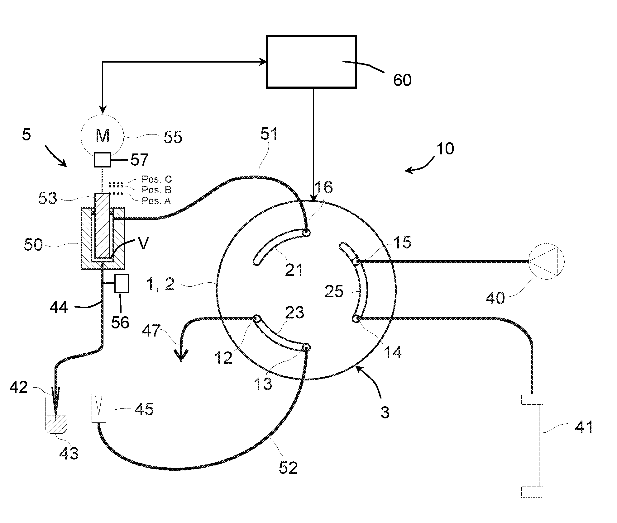
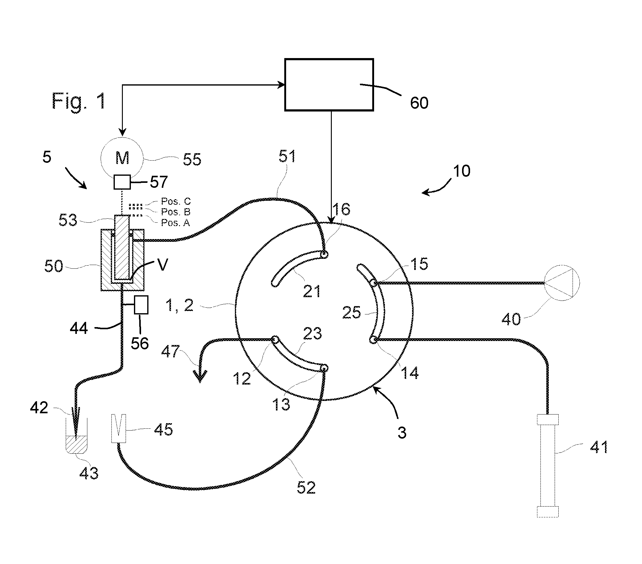
FIG. 1 shows a schematic representation of an HPLC system with a sample injector according to the invention, to which a chromatography column is connected, wherein the injection valve is situated in the LOAD position and the process of taking in a sample volume can begin in the state shown;
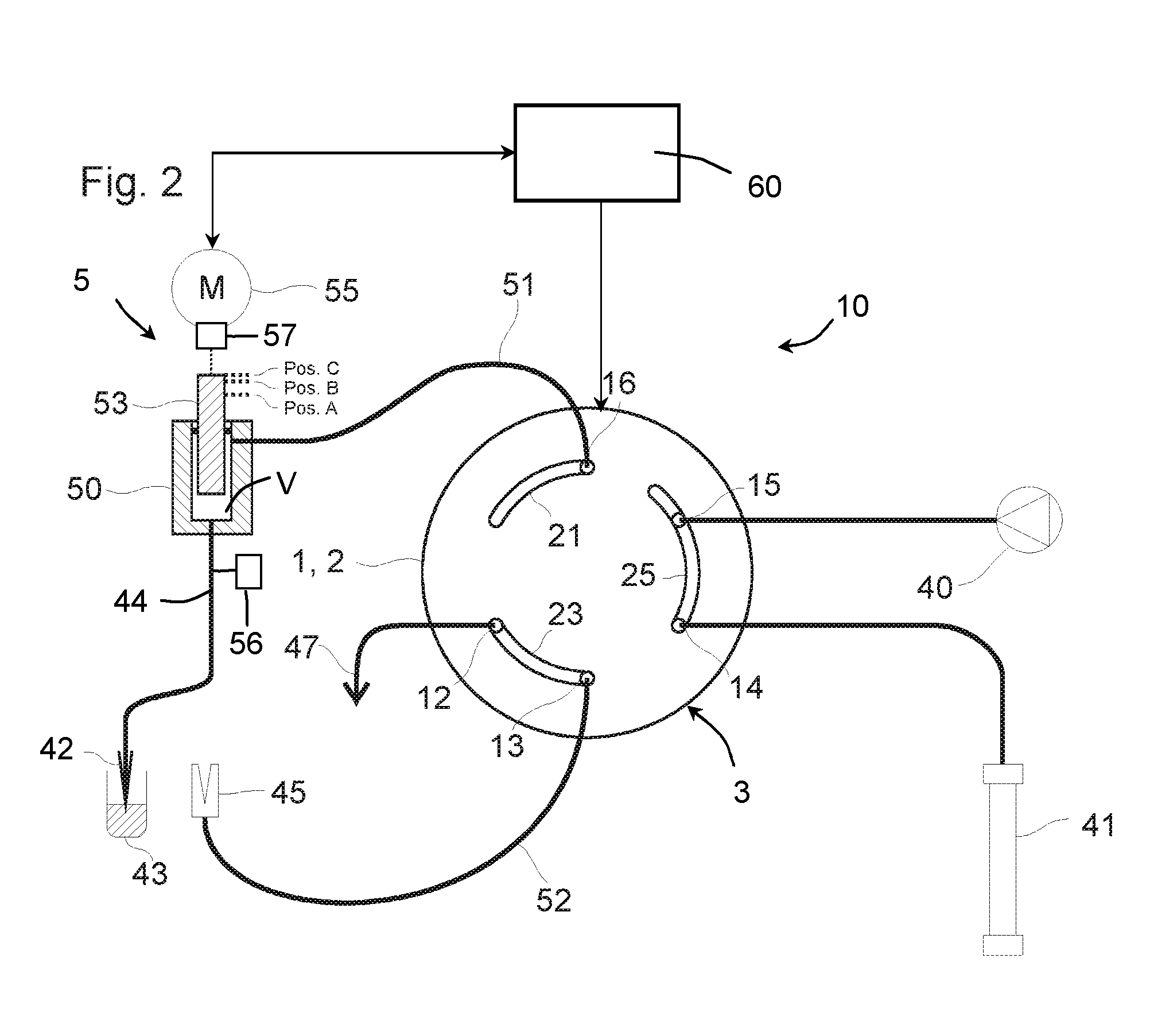
FIG. 2 shows the HPLC system of FIG. 1, wherein the plunger of the syringe was moved into the end position (position C) in order to take in the sample volume;
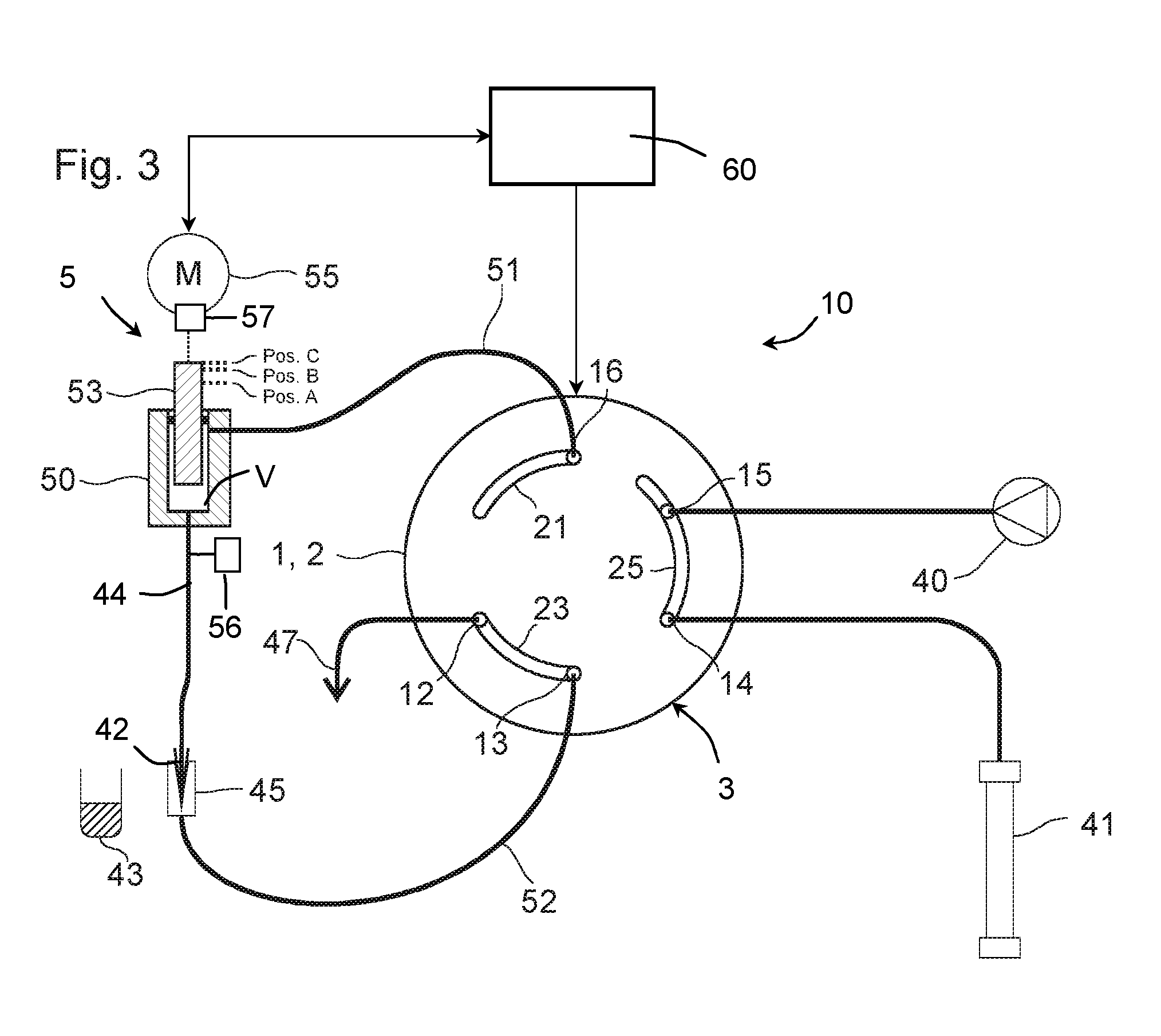
FIG. 3 shows the HPLC system of FIG. 2, wherein the sample needle was moved into the injection port;
FIG. 4 shows the HPLC system of FIG. 3, wherein the injection valve was changed over from the LOAD position into the PRESSURE COMPENSATION position;
FIG. 5 shows the HPLC system of FIG. 4, wherein the plunger was moved into the position B in order to realize a pressure compensation (pressure increase) in the sample loop;
FIG. 6 shows the HPLC system of FIG. 5, wherein the injection valve was changed over from the PRESSURE COMPENSATION position into the INJECT position;
FIG. 7 shows the HPLC system of FIG. 6, wherein the injection valve was changed over from the INJECT position into the PRESSURE COMPENSATION position after the injection of the sample volume;
FIG. 8 shows the HPLC system of FIG. 7, wherein the plunger was moved into the end position (position C) in order to realize a pressure compensation (pressure reduction), and
FIG. 9 shows the HPLC system of FIG. 8, wherein the injection valve was changed over from the PRESSURE COMPENSATION position into the LOAD position.
DESCRIPTION OF ILLUSTRATIVE EMBODIMENTS
FIG. 1 shows a schematic representation of an HPLC system with a sample injector 10 that operates in accordance with the Split Loop Principle and features a sample conveying device 5, an injection valve 3 and a high-pressure pump 40. The sample injector 10 furthermore features a sample loop that includes a first connecting piece 51 and a second connecting piece 52, 44. These may be comprised of a pressure-resistant line with a small diameter, for example in the form of a capillary tube of glass or stainless steel. The connecting piece 51 is connected to a first sample loop port 16 of the injection valve 3 and to the sample conveying device or its pump volume V, respectively. The second connecting piece is comprised of an intake segment 44 and a feed segment 52 and is realized in a separable fashion. For this purpose, the feed segment 52 leads into an injection port 45 that is connected to a second sample loop port 13 of the injection valve 3 via the feed segment 52. The intake segment 44 that is connected to the pump volume V of the sample conveying device 5 with one end features on its other end a sample needle 42, by means of which the intake segment 44 can be connected to the injection port 45.
However, the sample needle 42 can also be moved to a sample container 43 and take in a defined sample volume into the intake segment 44 as described in greater detail below. Furthermore, the sample needle 41 can also be moved to a (not-shown) container for a flushing fluid in order to withdraw flushing fluid for a flushing process and to clean the sample loop 51, 52, 44, the pump volume V and, if applicable, also the ports and the grooves or channels of the injection valve. Due to the special topology of the Split Loop Principle shown, flushing of the sample loop 51, 52, 44 and of the sample conveying device 5 is normally not required because they are flushed during an injection process anyway, namely with eluent supplied by the pump 40. However, the outside of the sample needle 42 can also be cleaned by immersing the needle into a container with cleaning or flushing fluid.
In the embodiment shown, the sample conveying device 5 comprises a syringe 50, in which a plunger 53 is guided in a displaceable and pressure-tight fashion. The plunger 53 is driven by means of a drive 55 that is realized, for example, in the form of a stepping motor. The drive 55 is controlled by a control unit 60. The control unit 60 also controls the change-over processes of the injection valve 3 that features a not-shown controllable drive.
A waste port 12 of the injection valve is connected to a waste line 47, from which fluid can be discharged into a not-shown waste reservoir.
The high-pressure pump 40 is connected to a high-pressure port 15 of the injection valve. A chromatography column 41 is connected to the other high-pressure port 14. The high-pressure pump 40 may be integrated into and form part of the sample injector or be arranged in another unit or a separate pump unit.
The injection valve 3 includes a stator 1 and a rotor 2. The stator 1 features the two high-pressure ports 14, 15, the two sample loop ports 13, 16 and the waste port 12. The injection valve 3 is connected to the other functional elements of the HPLC system via these ports and the above-described connecting lines that may be realized in the form of capillary connections. The high-pressure screw connections required for this purpose are not illustrated in FIG. 1 in order to provide a better overview. For reasons of simplicity, the injection valve is illustrated in the interface between the stator 1 and the rotor 2, wherein the design of the face of the stator 1 and the design of the face of the rotor 2 are shown in order to better comprehend the function of the injection valve. Within the injection valve 3, the ports are realized in the form of bores that lead to the other side of the stator 1. The rotor 2 features a number of arc-shaped grooves 21, 23, 25 that are exactly aligned with the bores of the input and output ports.
The rotor 2 is pressed against the stator with a certain pressing force such that a common interface between the rotor 1 and the stator 2 is formed, at which both components are mutually sealed. In this case, the pressing force is chosen so high that the arrangement also remains sealed at the highest pressures to be expected.
In the first LOAD position of the valve 3 illustrated in FIG. 1, the grooves 21, 23, 25 are aligned relative to the ports 12-16 in such a way that the grooves 23 and 25 respectively connect the two high-pressure ports 14, 15 and the waste port 12 to the sample loop port 13. In this LOAD position, the high-pressure pump 40 therefore conveys fluid in the direction of the chromatography column 41. Furthermore, the sample loop port 16 is closed in a pressure-tight fashion.
In the state illustrated in FIG. 1, the sample needle 42 is moved into the sample container 43 such that a sample volume can be taken in. For this purpose, the plunger 53 is situated in the position A and can be moved into the position C by the control unit 60 in order to take in the sample volume. The desired defined sample volume is then withdrawn into the intake segment 44, wherein the volume of the sample is smaller than the volume of the intake segment 44 such that the sample fluid cannot mix with the fluid supplied by the high-pressure pump in the pump volume. FIG. 2 shows the state of the HPLC system after the intake process is completed.
In order to inject the sample volume situated in the intake segment 44, the sample needle 42 is moved into the injection port 45. This port seals the needle point in a high-pressure-resistant fashion. This state is illustrated in FIG. 3.
In the next step, the pressure in the sample loop is adjusted to the operating pressure of the chromatography column 41, i.e., to the pressure, with which the high-pressure pump 40 supplies fluid to the inlet of the chromatography column 41. For this purpose, the injection valve is initially changed over into a PRESSURE COMPENSATION position, in which the connecting piece 51 and the second connecting piece or the feed segment 52 of the sample loop are not connected to the other components connected to the injection valve 3 (FIG. 4).
In this PRESSURE COMPENSATION position, the plunger 53 of the high-pressure-resistant sample conveying device is moved into the position B (FIG. 5). In order to prevent an interruption of the flow through the chromatography column 41 while conveying the volume required for the compression of the sample loop content, the groove 25 in the rotor 2 of the valve is realized in a correspondingly elongated fashion such that the two high-pressure ports 14, 15 are still connected in the PRESSURE COMPENSATION position. The travel of the plunger 53 from position C into position B required for building up the pressure can be calculated from the compressibility of the fluid volume enclosed in the sample conveying device 5 and in the sample loop, the elasticity of the arrangement and the current pump pressure. Alternatively, a pressure compensation can be achieved with the aid of a control circuit for the pressure in the high-pressure-resistant sample conveying device. For this purpose, the pressure needs to be measured at a suitable location and the position of the plunger 53 in the sample conveying device 5 needs to be adjusted by the drive 55 in such a way that the pressure corresponds to the required target pressure (=column pressure). Pressure measurement may be realized with a pressure sensor such as sensor 56 or indirectly by means of a force measurement. Conceivable solutions are force measurements on the plunger 53 or in the drive 55. After pressure equality is achieved, the valve is changed over into the INJECT position in order to inject the sample volume into the column 41 (FIG. 6).
In the embodiment shown, the control unit 60 measures the force that the drive 55 needs to exert in order to achieve a corresponding compression in the sample loop. For this purpose, the drive 55 may feature an integrated sensor 57, the signal of which is fed to the control unit 60 (as indicated with a double arrow between the drive 55 and the control unit 60). Due to this measure, the control unit can determine the actual pressure in the pump volume and therefore in the sample loop (the pressure drop in the connecting pieces and in the valve is negligibly small) and adjust this pressure to the desired value.
After the entire sample volume has been conveyed from the intake segment 44 to the column 41 by means of the fluid conveyed by the pump 40, the valve can be once again changed over into the PRESSURE COMPENSATION position in order to decompress the sample loop (FIG. 7).
The plunger 53 is moved from the position illustrated in FIG. 7 into position C. This causes the pressure in the sample loop to be adjusted to the atmospheric pressure. This state of the HPLC system is illustrated in FIG. 8. During this decompression time in the PRESSURE COMPENSATION position of the injection valve 3, the column 41 is already connected to the pump 40 via the elongated groove 25 in order to prevent pressure drops. The travel of the plunger 53 from position B to position C can either be calculated analogous to the compression in FIG. 5 or determined by measuring and controlling the pressure. Alternatively, the pressure can also be determined indirectly by means of a force measurement on the plunger 53 or on the drive 55 of the plunger.
After the sample loop has been decompressed, the valve 3 is changed over into the LOAD position (FIG. 9). No damaging flows in the injection valve occur during this process.
The plunger 53 of the high-pressure-resistant sample conveying device 5 can now be moved back into the starting position A. The excess quantity of fluid is discharged via the waste connection 47. The unpressurized needle 42 can subsequently be moved from the needle seat of the injection port 45 to the corresponding sample bottle in order to take in the next sample.
The position C during the decompression may also differ from the starting position A prior to the compression. For example, if gradients (time-controlled mixing ratio of the eluent) are pumped through the column, the position C at the end of the decompression may differ because the compressibility of the loop content may have changed.
The control unit 60 can store predetermined positions A, B, C and/or differences in the distance between these positions as a function of parameters of the entire sample injector, particularly the compressibility of the eluent, elasticity properties of the sample loop and the sample conveying device, etc. The plunger can then be automatically moved into these positions (i.e., without a control) or these positions may serve as approximate values or initial values for a controlled movement.
In order to determine the positions A, B, C and the respective travel of the plunger, a change-over of the injection valve 3 may be carried out without compression or decompression, respectively. The pressure drop can then be determined by means of a pressure sensor and the required travel as well as the respective positions B or C can be determined based on this pressure drop. The thusly determined values can then be stored and used for other change-over processes, in which a compression or decompression takes place. A corresponding sensor may also be provided in the pump 40. Pumps of this type for HPLC always feature a pressure sensor for controlling the conveyed eluent anyway. The compressibility of the medium, particularly of the eluent, can also be determined by means of the pump 40. Such pumps are realized, for example, in the form of dual-plunger pumps, in which the change-over from one plunger to the other plunger is suitably controlled or regulated by means of a pressure sensor and a control unit in such a way that a highly constant flow rate is achieved. Since the compressibility of the medium also needs to be taken into account during this change-over process, the compressibility can be determined by suitably controlling the dual-plunger pump during the change-over from one plunger to the other plunger and fed to the control unit 60 as information. This connection between the pump 40 and the control unit 60 is merely illustrated with broken lines in FIG. 9.
In the automatic sample injector shown, it is therefore ensured that the pressure in the sample loop is adjusted to the current operating pressure of the chromatography column by means of decompression in the sufficiently (high) pressure-resistant sample conveying device when the injection valve is in a special intermediate position, namely the PRESSURE COMPENSATION position, before the intake segment is moved into the flow path toward the chromatography column, i.e., before the injection valve is changed over into the INJECT position.
In addition, the pressure in the sample loop is adjusted to the atmospheric pressure (decompression) in the same intermediate position of the injection valve, namely the PRESSURE COMPENSATION position, by taking in an exactly defined additional fluid quantity into the sample conveying device before the sample loop is separated in order to take in a sample volume from a sample container, i.e., before the injection valve is changed over into the LOAD position.
The compression and decompression volumes do not flow through the injection valve. Consequently, the service life of the (high-pressure) injection valve of the sample injector is only limited by the unavoidable abrasion between the rotor and the stator and, if applicable, the abrasive effect, for example, of dirt particles or sample material.
As used herein, whether in the above description or the following claims, the terms "comprising," "including," "carrying," "having," "containing," "involving," and the like are to be understood to be open-ended, that is, to mean including but not limited to. Any use of ordinal terms such as "first," "second," "third," etc., in the claims to modify a claim element does not by itself connote any priority, precedence, or order of one claim element over another, or the temporal order in which acts of a method are performed. Rather, unless specifically stated otherwise, such ordinal terms are used merely as labels to distinguish one claim element having a certain name from another element having a same name (but for use of the ordinal term).
The above described preferred embodiments are intended to illustrate the principles of the invention, but not to limit the scope of the invention. Various other embodiments and modifications to these preferred embodiments may be made by those skilled in the art without departing from the scope of the present invention.
* * * * *
References
D00000
D00001
D00002
D00003
D00004
D00005
D00006
D00007
D00008
D00009
XML
uspto.report is an independent third-party trademark research tool that is not affiliated, endorsed, or sponsored by the United States Patent and Trademark Office (USPTO) or any other governmental organization. The information provided by uspto.report is based on publicly available data at the time of writing and is intended for informational purposes only.
While we strive to provide accurate and up-to-date information, we do not guarantee the accuracy, completeness, reliability, or suitability of the information displayed on this site. The use of this site is at your own risk. Any reliance you place on such information is therefore strictly at your own risk.
All official trademark data, including owner information, should be verified by visiting the official USPTO website at www.uspto.gov. This site is not intended to replace professional legal advice and should not be used as a substitute for consulting with a legal professional who is knowledgeable about trademark law.